


N843L

SHIBAURA DIESEL ENGINE
MODELS: S773L, N843, N843L
WORKSHOP MANUAL
SUPPORTED BY HUSTLER TURF EQUIPMENT AND EXCEL INDUSTRIES, INC.

FOREWORD
This workshop Manual includes repair and adjustment procedures required for the diesel engine models S7 73L, N843,
and N843L.
When servicing to keep the engine in the best condition, you will find this Manual very useful as a guidebook.
This Workshop Manual was prepared in Jul. 2008. Specifications contained in this Manual are subject to change without
notice for subsequent engineering changes.
109823_2/09 c-2

Table of Contents
FOREWORD . . . . . . . . . . . . . . . . . . . . . . . . . . . . . . . . . . . . . . . . . . . . . . . . . . . . . .c-2
Section 1: Safety. . . . . . . . . . . . . . . . . . . . . . . . . . . . . . . . . . . . . . . . . . .1-1
Before beginning service or repair. . . . . . . . . . . . . . . . . . . . . . . . . . . . . . . . . . . . . .1-1
Avoid Fire Hazards . . . . . . . . . . . . . . . . . . . . . . . . . . . . . . . . . . . . . . . . . . . . . . . . .1-1
Prepare For Emergencies . . . . . . . . . . . . . . . . . . . . . . . . . . . . . . . . . . . . . . . . . . . .1-1
Engine Starting Safety. . . . . . . . . . . . . . . . . . . . . . . . . . . . . . . . . . . . . . . . . . . . . . .1-1
Prevent Battery Explosions . . . . . . . . . . . . . . . . . . . . . . . . . . . . . . . . . . . . . . . . . . .1-1
Avoid Acid Burns . . . . . . . . . . . . . . . . . . . . . . . . . . . . . . . . . . . . . . . . . . . . . . . . . . .1-2
Avoid High-pressure Fluids . . . . . . . . . . . . . . . . . . . . . . . . . . . . . . . . . . . . . . . . . . .1-2
Understand Correct Service . . . . . . . . . . . . . . . . . . . . . . . . . . . . . . . . . . . . . . . . . .1-2
General Maintenance Precautions . . . . . . . . . . . . . . . . . . . . . . . . . . . . . . . . . . . . .1-2
Fuel Handling. . . . . . . . . . . . . . . . . . . . . . . . . . . . . . . . . . . . . . . . . . . . . . . . . . . . . .1-3
Wear Protective Clothing. . . . . . . . . . . . . . . . . . . . . . . . . . . . . . . . . . . . . . . . . . . . .1-3
Section 2: General . . . . . . . . . . . . . . . . . . . . . . . . . . . . . . . . . . . . . . . . .2-1
General Notes Before Service. . . . . . . . . . . . . . . . . . . . . . . . . . . . . . . . . . . . . . . . .2-1
Fundamental Instructions On Service . . . . . . . . . . . . . . . . . . . . . . . . . . . . . . . . . . .2-1
Torque Specifications . . . . . . . . . . . . . . . . . . . . . . . . . . . . . . . . . . . . . . . . . . . . . . .2-2
Engine Sectional Drawing . . . . . . . . . . . . . . . . . . . . . . . . . . . . . . . . . . . . . . . . . . . .2-3
Specifications. . . . . . . . . . . . . . . . . . . . . . . . . . . . . . . . . . . . . . . . . . . . . . . . . . . . . .2-4
Engine Removal . . . . . . . . . . . . . . . . . . . . . . . . . . . . . . . . . . . . . . . . . . . . . . . . . . .2-5
Parts and Descriptions. . . . . . . . . . . . . . . . . . . . . . . . . . . . . . . . . . . . . . . . . . . . . . .2-6
Section 3: Disassembly And Inspection Of Engine. . . . . . . . . . . . . . . . .3-1
Rocker arm assembly . . . . . . . . . . . . . . . . . . . . . . . . . . . . . . . . . . . . . . . . . . . . . . .3-1
Cylinder head assembly . . . . . . . . . . . . . . . . . . . . . . . . . . . . . . . . . . . . . . . . . . . . .3-2
Cylinder block . . . . . . . . . . . . . . . . . . . . . . . . . . . . . . . . . . . . . . . . . . . . . . . . . . . . .3-4
Piston and piston ring . . . . . . . . . . . . . . . . . . . . . . . . . . . . . . . . . . . . . . . . . . . . . . .3-5
Connecting rod . . . . . . . . . . . . . . . . . . . . . . . . . . . . . . . . . . . . . . . . . . . . . . . . . . . .3-7
Connecting rod bearing . . . . . . . . . . . . . . . . . . . . . . . . . . . . . . . . . . . . . . . . . . . . . .3-7
Disassembly, inspection and reassembly of bearing holder . . . . . . . . . . . . . . . . . .3-9
Crankshaft bearing (bushing) . . . . . . . . . . . . . . . . . . . . . . . . . . . . . . . . . . . . . . . . .3-9
Crankshaft . . . . . . . . . . . . . . . . . . . . . . . . . . . . . . . . . . . . . . . . . . . . . . . . . . . . . . . .3-10
Flywheel and ring gear . . . . . . . . . . . . . . . . . . . . . . . . . . . . . . . . . . . . . . . . . . . . . .3-11
Cam shaft assembly . . . . . . . . . . . . . . . . . . . . . . . . . . . . . . . . . . . . . . . . . . . . . . . .3-12
Timing gear . . . . . . . . . . . . . . . . . . . . . . . . . . . . . . . . . . . . . . . . . . . . . . . . . . . . . . .3-12
Oil flow. . . . . . . . . . . . . . . . . . . . . . . . . . . . . . . . . . . . . . . . . . . . . . . . . . . . . . . . . . .3-13
Oil pump . . . . . . . . . . . . . . . . . . . . . . . . . . . . . . . . . . . . . . . . . . . . . . . . . . . . . . . . .3-14
Oil filter. . . . . . . . . . . . . . . . . . . . . . . . . . . . . . . . . . . . . . . . . . . . . . . . . . . . . . . . . . .3-14
Water pump assembly and thermostat . . . . . . . . . . . . . . . . . . . . . . . . . . . . . . . . . .3-15
Radiator . . . . . . . . . . . . . . . . . . . . . . . . . . . . . . . . . . . . . . . . . . . . . . . . . . . . . . . . . .3-15
Fuel filter . . . . . . . . . . . . . . . . . . . . . . . . . . . . . . . . . . . . . . . . . . . . . . . . . . . . . . . . .3-16
Governor . . . . . . . . . . . . . . . . . . . . . . . . . . . . . . . . . . . . . . . . . . . . . . . . . . . . . . . . .3-16
Injection pump . . . . . . . . . . . . . . . . . . . . . . . . . . . . . . . . . . . . . . . . . . . . . . . . . . . . .3-16
Nozzle and holder . . . . . . . . . . . . . . . . . . . . . . . . . . . . . . . . . . . . . . . . . . . . . . . . . .3-17
Section 4: Engine Re-assembly . . . . . . . . . . . . . . . . . . . . . . . . . . . . . . .4-1
Relief valve assembly with O-Ring. . . . . . . . . . . . . . . . . . . . . . . . . . . . . . . . . . . . . .4-1
Crank shaft and bearing holder assembly. . . . . . . . . . . . . . . . . . . . . . . . . . . . . . . .4-1
Measure the end play of crankshaft. . . . . . . . . . . . . . . . . . . . . . . . . . . . . . . . . . . . .4-1
Oil seal. . . . . . . . . . . . . . . . . . . . . . . . . . . . . . . . . . . . . . . . . . . . . . . . . . . . . . . . . . .4-2
Rear plate . . . . . . . . . . . . . . . . . . . . . . . . . . . . . . . . . . . . . . . . . . . . . . . . . . . . . . . .4-2
t-1 109823 2/09

Flywheel . . . . . . . . . . . . . . . . . . . . . . . . . . . . . . . . . . . . . . . . . . . . . . . . . . . . . . . . . 4-2
Piston and connecting rod assembly . . . . . . . . . . . . . . . . . . . . . . . . . . . . . . . . . . . 4-3
Suction pipe · Suction filter . . . . . . . . . . . . . . . . . . . . . . . . . . . . . . . . . . . . . . . . . . . 4-3
Oil pan. . . . . . . . . . . . . . . . . . . . . . . . . . . . . . . . . . . . . . . . . . . . . . . . . . . . . . . . . . . 4-4
Oil dipstick · Dipstick guide . . . . . . . . . . . . . . . . . . . . . . . . . . . . . . . . . . . . . . . . . . . 4-4
Front plate. . . . . . . . . . . . . . . . . . . . . . . . . . . . . . . . . . . . . . . . . . . . . . . . . . . . . . . . 4-4
Camshaft assembly · Tachometer shaft plate. . . . . . . . . . . . . . . . . . . . . . . . . . . . . 4-4
Idle gear · Oil pump assembly. . . . . . . . . . . . . . . . . . . . . . . . . . . . . . . . . . . . . . . . . 4-5
Timing gear case · Cover . . . . . . . . . . . . . . . . . . . . . . . . . . . . . . . . . . . . . . . . . . . . 4-5
Crankshaft pulley . . . . . . . . . . . . . . . . . . . . . . . . . . . . . . . . . . . . . . . . . . . . . . . . . . 4-6
Injection pump assembly. . . . . . . . . . . . . . . . . . . . . . . . . . . . . . . . . . . . . . . . . . . . . 4-6
‘Oil filter. . . . . . . . . . . . . . . . . . . . . . . . . . . . . . . . . . . . . . . . . . . . . . . . . . . . . . . . . . 4-6
Engine stop solenoid. . . . . . . . . . . . . . . . . . . . . . . . . . . . . . . . . . . . . . . . . . . . . . . . 4-6
Cylinder head assembly . . . . . . . . . . . . . . . . . . . . . . . . . . . . . . . . . . . . . . . . . . . . . 4-7
Cap · Push rod · Rocker arm assembly . . . . . . . . . . . . . . . . . . . . . . . . . . . . . . . . . 4-8
Valve clearance adjustment . . . . . . . . . . . . . . . . . . . . . . . . . . . . . . . . . . . . . . . . . . 4-8
Oil pressure switch . . . . . . . . . . . . . . . . . . . . . . . . . . . . . . . . . . . . . . . . . . . . . . . . . 4-9
Oil pipe . . . . . . . . . . . . . . . . . . . . . . . . . . . . . . . . . . . . . . . . . . . . . . . . . . . . . . . . . . 4-9
Water pump assembly · Bypass hose. . . . . . . . . . . . . . . . . . . . . . . . . . . . . . . . . . . 4-9
Valve cover . . . . . . . . . . . . . . . . . . . . . . . . . . . . . . . . . . . . . . . . . . . . . . . . . . . . . . . 4-9
Glow plug, Connector . . . . . . . . . . . . . . . . . . . . . . . . . . . . . . . . . . . . . . . . . . . . . . . 4-9
Section 5: Electrical Systems. . . . . . . . . . . . . . . . . . . . . . . . . . . . . . . . . 5-1
Fuel Shutoff Solenoid . . . . . . . . . . . . . . . . . . . . . . . . . . . . . . . . . . . . . . . . . . . . . . . 5-1
Engine Glow Plugs . . . . . . . . . . . . . . . . . . . . . . . . . . . . . . . . . . . . . . . . . . . . . . . . . 5-2
Engine Oil Pressure Switch. . . . . . . . . . . . . . . . . . . . . . . . . . . . . . . . . . . . . . . . . . . 5-3
Alternator (40 amp version) (No. 185046320). . . . . . . . . . . . . . . . . . . . . . . . . . . . . 5-4
Alternator diagnostic procedures . . . . . . . . . . . . . . . . . . . . . . . . . . . . . . . . . . . . . . 5-5
Maintenance . . . . . . . . . . . . . . . . . . . . . . . . . . . . . . . . . . . . . . . . . . . . . . . . . . . . . . 5-11
Trouble Shooting. . . . . . . . . . . . . . . . . . . . . . . . . . . . . . . . . . . . . . . . . . . . . . . . . . . 5-12
Starter Motor (M001T66081) (No. 185086551). . . . . . . . . . . . . . . . . . . . . . . . . . . . 5-13
Maintenance . . . . . . . . . . . . . . . . . . . . . . . . . . . . . . . . . . . . . . . . . . . . . . . . . . . . . . 5-18
Trouble shooting . . . . . . . . . . . . . . . . . . . . . . . . . . . . . . . . . . . . . . . . . . . . . . . . . . . 5-19
Section 6: Trouble-Shooting . . . . . . . . . . . . . . . . . . . . . . . . . . . . . . . . . 6-1
Section 7: Servicing Specifications . . . . . . . . . . . . . . . . . . . . . . . . . . . . 7-1
Index . . . . . . . . . . . . . . . . . . . . . . . . . . . . . . . . . . . . . . . . . . . . . . . . . . . i-1
109823 2/09 t-2

SECTION 1: SAFETY
This safety alert symbol is used to call attention to a
message intended to provide a reasonable degree of
PERSONAL SAFETY for operators and other persons
during the normal operation and servicing of this
equipment.
BEFORE BEGINNING SERVICE OR REPAIR
1. Read and understand all instructions and safety
warnings in this manual and on any decals on the
equipment.
2. Make sure engine and work area are clean.
3. Place engine or machine on stable, level work
area and/or use an approved engine stand.
4. Stop engine and remove ignition key.
5. Allow engine to cool before preforming service.
6. Disconnect negative (-) battery cable before preforming service or repair.
DANGER—denotes immediate hazards which WILL
result in severe personal injury or death.
WARNING—denotes a hazard or unsafe practice which
COULD result in severe personal injury or death.
▲ Provide adequate ventilation when charging
batteries.
▲ Do not smoke near battery.
▲ Never check fuel level with an open flame.
▲ Never use an open flame to look for leaks
anywhere on the equipment.
▲ Never use an open flame as light anywhe re on or
around the equipment.
▲ When preparing engine for storage, remember
that inhibitor is volatile and therefore dangerous.
Seal and tape openings after adding the inhibitor.
Keep container tightly closed when not in use.
▲ Inspect electrical wiring for worn or frayed
insulation. Install new wiring if wires are damaged.
PREPARE FOR EMERGENCIES
Be prepared if a fire starts.
▲
▲ Keep a first aid kit and fire extinguishers available.
▲ Keep emergency numbers for doctor, ambulance
service, hospital, and fire department near the
telephone.
ENGINE STARTING SAFETY
▲ Do not start engine by shorting across starter
terminals.
NOTE:—emphasizes general information worthy of
special attention.
All operators and mechanics should read this manual, and
be instructed about safe operating and maintenance
procedures. If the operators or mechanics cannot read
and understand English, it is the owner’s responsibility to
explain this material to them.
To reduce the potential for injury, comply with these safety
instructions and always pay attention to the safety alert
symbol, which means DANGER or WARNING—“personal
safety instructions.” Failure to comply with the instructions
may result in personal injury or death.
▲
AVOID FIRE HAZARDS
Be prepared if an accident or fire should occur.
▲
Know where the first aid kit and the fire
extinguishers are located and how to use them.
▲ Unauthorized modifications to the engine may
impair the function and/or safety and affect engine
life.
PREVENT BATTERY EXPLOSIONS
109823 2/09 1-1
▲
Battery gas can explode. Keep sparks and flames
away from batteries. Use a flashlight to check
battery electrolyte level.
▲ Never check battery charge by placing a metal
object across the posts. Use a voltmeter or
hydrometer.
▲ Always remove grounded (-) battery cable first
and replace it last.
leak under pressure, use a piec e of cardboard or
wood—never use your hands. Relieve all
pressure in the system before disconnecting or
working on hydraulic lines. To relieve pressure,
lower all attachments and shut off engine.
AVOID ACID BURNS
Sulfuric acid in battery electrolyte is poisonous. It
▲
is strong enough to burn skin, eat holes in clothing
and cause blindness if splashed in eyes.
Avoid the hazard by:
1. Filling batteries in a well-ventilated area.
2. Wearing eye protection and rubber gloves.
3. Avoiding breathing fumes when electrolyte is
added.
4. Avoiding spilling or dripped electrolyte.
If you spill acid on yourself:
1. Flush your skin with water.
2. Apply baking soda or lime to help neutralize the
acid.
3. Flush your eyes with water for 10-15 minutes. Get
medical attention immediately.
If acid is swallowed:
1. Drink large amounts of water or milk.
2. Then drink milk of magnesia, beaten eggs or vegetable oil.
3. Get medical attention immediately.
AVOID HIGH-PRESSURE FLUIDS
▲ Escaping fluid (fuel or hydraulic oil) under
pressure can penetrate skin causing serious
injury . Hydraulic oil may cause infection in a minor
cut or opening in the skin. If exposed to hydraulic
fluid, see a doctor at once.
UNDERSTAND CORRECT SERVICE
Be sure you understand a service procedure
▲
before you work on the machine.
▲ Unauthorized modifications to the machine may
impair the function and/or safety and affect
machine life.
▲ If it is necessary to make checks with the engine
running, always use two people - with the
operator at the controls, able to see the person
doing the checking. Use extra safety precautio ns.
▲ Use caution when running engines to avoid
moving and hot parts.
▲ Use the correct tool for the work. Do not use
makeshift tools or substitute parts.
GENERAL MAINTENANCE PRECAUTIONS
Do not perform work or service while under the
▲
influence of alcohol, medication, or other
substances, or when fatigued.
▲ Never run the engine in an enclos ed area unless
exhaust is vented to the outside. Exhaust gases
contain carbon monoxide which is odorless and
deadly poison.
▲ Before applying pressure to fuel or hydraulic
system, make sure all connections are tight and
all hoses and lines are in good condition. To find a
▲ Never remove radiator cap while the engine is
running. Allow engine to cool and remove cap
slowly to relieve pressure.
▲ Never attempt to make any adjust ment s or rep a irs
to the tractor drive system, mower deck or any
1-2 109823 2/09
attachment while the tractor engine is ru nning or
deck clutch is engaged.
▲ Repairs or maintenance requiring engine power
should be performed by trained personnel only.
▲ Never work under the machine or attachment
unless it is safely supported with stands, blocks or
a hoist.
▲ Always transport machine in a safe manner.
FUEL HANDLING
Fuel is extremely flammable and explosive under
▲
certain conditions Do not smoke while you fill the
fuel tank, service fuel system or handle highly
flammable material.
▲ Do not remove fuel cap or add fuel t o tank when
engine is hot or running. Allow engine to cool for
several minutes.
▲ Do not use open pans of gasoline or diesel fuel
for cleaning parts. Use good commercial,
nonflammable solvents.
▲ Never refuel tractor while engine is running; never
refuel near an open flame or near devices which
can create a spark. Refuel outdoors preferably or
in well ventilated areas.
▲ Immediately clean up any spilled fuel.
▲ dispose of all fluids properly, and in an
environmently correct maner.
WEAR PROTECTIVE CLOTHING
▲
Wear fairly tight fitting clothing and safety
equipment.
▲ Always wear adequate eye protection when
servicing the hydraulic system and battery, or
when grinding mower blades and removing
accumulated debris.
▲ Prolonged exposure to loud noise can cause
impairment or loss of hearing. Always wear
adequate ear protection, such as earplugs, when
operating this equipment as prolonged exposure
to uncomfortable or loud noises can cause
impairment or loss of hearing. Do not wear radios
or music headphones while operating the
machinery. Safe operation requires your full
attention.
109823 2/09 1-3

1-4 109823 2/09

SECTION 2: GENERAL
General Notes Before Service
1. Clean the exterior of the engine, drain oil, fuel and cooling water as necessary before disassembly.
2. Keep the service shop clean, free from dust, and with adequate lighting.
3. Remove oil and grease from disassembled parts, and place them in groups on a clean t abl e.
4. Be safety conscience; check equipment, tools and wear appropriate clothing.
5. Measurements are in the following format:
Type of measurement Units
Length in(mm)
Torque lbf•ft(Nm){kgfm}
Weight oz(g)
Temperature °F(°C)
Pressure
Fundamental Instructions On Service
1. Keep the engine clean, disassemble only those components that need to be disassembled.
The engine is built to close tolerances and clearances.
2. Retain replaced parts for the customer.
3. Always use machine model, serial number, part number and parts name when ordering service parts.
4. Prelube all moving parts during reassembly.
5. Tighten bolts and nuts to specified torque with proper tools, unless otherwise instructed.
PSI(MPa){kgf/cm
2
}
109823 2/09 2-1

Torque Specifications
Bolt
Size
M5 4T, 4.8 0.8 18.6-35.4 in•lb
M6 4T, 4.8 1.0 43.4-61.1 in•lb
M8 4T, 4.8 1.25 115.1-150.5 in•lb
M10 4T, 4.8 1.5 18.4-24.3 25-33 1.25 20.7-26.6 28-36
M12 4T, 4.8 1.75 27.3-34.7 37-47 1.25 31.7-40.6 43-55
M14 4T, 4.8 2.0 46.5-59.0 63-80 1.5 51.6-64.2 70-87
M16 4T, 4.8 2.0 63.4-81.1 86-110 1.5 67.1-84.1 91-114
M18 4T, 4.8 2.0 83.3-104.0-5.1 113-141 1.5 97.4-119.5 132-162
M20 4T, 4.8 2.5 106.2-132.8 144-180 1.5 126.9-154.9 172-210
Grade No. Coarse Thread Fine Thread
7T, 8T, 8.8 43.4-61.1 in•lb
10T, 11T 59.3-83.2 in•lb
7T, 8T, 8.8 73.5-100.0 in•lb
10T, 11T 106.2-141.6 in•lb
7T, 8T, 8.8 17.0-20.7 23-28 19.2-25.1 26-34
10T, 11T 20.7-26.6 28-36 22.1-29.5 30-40
7T, 8T, 8.8 32.5-41.3 44-56 36.1-46.5 49-63
10T, 11T 39.8-51.6 54-70 42.8-54.6 58-74
7T, 8T, 8.8 48.7-61.2 66-83 55.3-69.3 75-94
10T, 11T 67.9-85.6 92-116 73.0-93.7 99-127
7T, 8T, 8.8 76.7-97.4 104-132 86.3-109.2 117-148
10T, 11T 102.5-129.1 139-175 109.9-135.7 149-184
7T, 8T, 8.8 109.9-136.4 149-185 115.8-141.6 157-192
10T, 11T 151.2-188.1 205-255 163.0-198.4 221-269
7T, 8T, 8.8 144.6-174.1 196-236 170.4-205.8 231-279
10T, 11T 202.8-245.6 275-333 219.8-270.7 298-367
7T, 8T, 8.8 177.0-213.9 240-290 202.8-245.6 275-333
10T, 11T 267.7-325.3 363-441
Pitch
(mm)
Tightening torque Pitch
lbf•ft N•m lbf•ft N•m
f
f
f
f
f
f
f
2.8-4.0 ----- -----
4.9-6.9
6.7-9.4
4.9-6.9
8.3-11.3
12-16
13-17 1.0 11.1-14.8 15-20
(mm)
Tightening torque
2-2 109823 2/09

Engine Sectional Drawing
109823 2/09 2-3

Specifications
Items Specifications
Engine model S773L N843 N843L
Engine type 4-cycle water cooled in-line
overhead valve
No. of cylinders-bore ×
stroke in(mm)
Piston displacement cc 1131 1496 1662
Compression ratio 23.5 to 1 22.5 to 1 22.5 to 1
Combustion chamber type Special swirl chamber Special swirl chamber Special swirl chamber
*Rated output (Gross)
HP(kW)/rpm
Fuel used SAE No.2–D, DIN 51601,
Injection pump Bosch, PFR type Bosch, PFR type Bosch, PFR type
Injection nozzle Throttle type Throttle type Throttle type
Injection governor Centrifugal all–speed con-
*Alternator, voltage. Output 12V–40A 12V–40A 12V–40A
*Starter, Voltage. Output 12V–1.2kW 12V–2.0kW 12V–2.0kW
3-3.031(77) × 3.189(81) 3 - 3.307(84) x 3.54(90) 3 - 3.307(84) x 3.94(100)
25(18.3)/2800 30(22.6)/2800 34(25.1)/2800
BS class A-1
trol
4-cycle water cooled in-line
overhead valve
SAE No.2–D, DIN 51601,
BS class A-1
Centrifugal all–speed con-
trol
4-cycle water cooled in-line
overhead valve
SAE No.2–D, DIN 51601,
BS class A-1
Centrifugal all–speed con-
trol
Lubrication method Pressurized circulation by
trochoid pump
Engine oil used API grade CD API grade CD API grade CD
*Lubrication oil volume
US Qts(L)
Cooling water volume
(Engine only) US Qts(L)
*Engine dry weight lbs(Kg) 207(94) 331(150) 353(160)
Engine
dimensions
Air cleaner Dry type
Notes: 1. The specifications above are subject to change without notice.
*Overall length
in(mm)
*Overall width
in(mm)
*Overall height
in(mm)
5.2(4.9) 6.3(6) 6.3(6)
2.0(1.9) 2.9(2.7) 3.0(2.8)
19.69(500) 21.0(534) 21.0(534)
15.28(388) 18.1(459) 18.1(459)
23.31(592) 25.9(657) 27.1(689)
Pressurized circulation by
trochoid pump
Pressurized circulation by
trochoid pump
2-4 109823 2/09

Engine Removal
Fig. 2-1
1. Water temperature switch
2. Water temperature sensor
3. Radiator hose
4. Alternator
5. Starting motor
Fig. 2-2
1. Air cleaner clogging
sensor
2. Ground wire
3. Glow plug connector
4. Fuel return hose
Fig. 2-3
1. Engine stop solenoid
2. Throttle cable
3. Fuel hose
4. Hydraulic oil pump
5. Engine mounting
hardware
6. Drain cock
3
2
1
4
5
4
3
1
2
3
1
2
4
6
5
Note: Asterisks (*). Items may vary depending on
the type of equipment in which the engine
is Installed.
1. If necessary, remove engine cover or
hood.
2. Remove the muffler and mounting
brackets from the engine.
3. Disconnect the wiring from the air
cleaner clogging sensor if so equipped.
4. Disconnect the wiring from the water
temperature sensor and water temperature switch.
5. Remove the radiator hoses from the
engine.
6. Disconnect the wiring from the alternator.
7. Disconnect the wiring from the starting
8. Remove the ground wire and bolt from
9. Disconnect the fuel return hose from
10. Disconnect the wiring from the engine
11. Disconnect the wiring from the glow
12. Disconnect the wiring from the engine
13. Disconnect the fuel line from the injec-
14. Remove the throttle cable from the
15. Disconnect the drain hose from the
16. Disconnect the oil hoses from the
17. Remove the engine mounting hardware
motor.
the cylinder head.
the fuel return line.
oil pressure switch.
plug connector.
stop solenoid.
tion pump.
engine
drain cock.
hydraulic oil pump.
and hoist the engine from the frame.
109823 2/09 2-5

Parts and Descriptions
5
1
2
4
3
6
7
Index Description
1 Alternator
2 Oil filter
3 Relief valve
4 Oil level gauge•Gauge guide
5 Engine stop solenoid•Seal washer
6 Fuel injection lines
7 Injection pump assembly and shim
Note:
1. Remove the injection fuel lines and engine stop solenoid before removing the injection pump.
2. Raise the injection pump and disconnect the governor link from the
control rack by removing the snap pin.
3. Injection timing is set by the shims between injection pump and block.
Note thickness and number when removing the injection pump.
4. Visually inspect the shim to determine if it is reusable or needs to be
replaced
109823 2/09 2-6

Index Description
9
8
13
10
11
17
16
18
15
12
14
14
15
8 Fuel return line
9 Injection nozzle•Gasket
10 Oil transfer pipe•Eye bolt •Seal washer
11 Connector•Glow plug
12 Oil pressure switch
13 Thermostat housing•Gasket
14 Valve cover•O-ring•Intake manifold•Spacer
15 Rocker arm assembly•O-ring•Cap
NOTE: Remove the caps from intake valves and exhaust valves.
16 Push rod
17 Cylinder head assembly•Head gasket
NOTE: Loosen the cylinder head bolts in several steps and remove the cylinder head
assembly.
18 Tappet
109823 2/09 2-7

Index Description
20
21
20
22
23
24
25
26
27
20 V-belt•Cooling fan•Fan holder•Fan pulley
21 Water pump assembly•Gasket
22 Crankshaft pulley and nut
23 Not available
24 Timing gear case assembly•Gasket
Note: Remove the engine stop solenoid and injection pump assembly first.
25 Idle gear•Oil pump assembly
26 Cam shaft assembly•Plate
Note: Remove the bolts and plate before pulling the camshaft assembly.
27 Front plate•Gasket
109823 2/09 2-8

28
29
30
31
33
32
33
Index Description
28 Oil pan•Gasket•Suction filter•Suction pipe
29 Fly wheel
30 Rear plate or Flywheel cover
31 Oil seal
32 Piston and connecting rod assembly
NOTE:
1. Before extracting piston, remove the carbon deposit from the top of the
cylinder.
2. Keep pistons, connecting rods, caps and bearings grouped by cylinder
number and reassemble to their original locations.
33 Crank shaft and bearing holder assembly
Note: Remove the bolts for bearing holders, and remove the crankshaft and bearing
holder assembly as an assembly.
109823 2/09 2-9

2-10 109823 2/09
SECTION 3: DISASSEMBLY AND INSPECTION OF ENGINE
Fig. 3-1
1. Screw
2. Rocker arm shaft
3. Rocker arm
4. Spring
5. Shim
3
5
1
2
4
Fig. 3-2
Fig. 3-3
Clearance
Caution: before starting disassembly
1. Check the cylinder block and cylinder head for wear, leakage or damage.
2. Clean oil passages with compressed air and check for clogging.
3. Thoroughly clean parts to remove dust, contaminated oil, carbon, and other foreign material.
4. Remove carbon deposits on the piston, cylinder head, valves, etc. being careful not to damage parts. (Especially for aluminum alloy parts.)
5. Valves, pistons, connecting rods, bearings and other parts, should be marked indicating
cylinder number and reassembled to the original cylinder location.
Rocker arm assembly
Disassembly
1. Screw in an M8 bolt at the front en d of the rocker arm
shaft and extract the rocker arm shaft.
2. Take out the spring, shim and rocker arm from the
rocker arm bracket.
Inspection and service
1. Using a micrometer, check outside diameter of the
rocker arm shaft. If the shaft is worn beyond the
service limit, replace the part.
Wear of rocker arm shaft ø in(mm)
Standard assembling value Service limit
0.4587-0.4594(11.65-11.67) Less than 0.4555(11.57)
2. Measure the inside diameter of the rocker arm.
Check the clearance between the rocker arm and
rocker arm shaft. If the clearance is beyond the
service limit, replace the part.
Clearance between rocker arm and rocker arm shaft
Standard assembling value Service limit
0.0013-0.0027(0.032–0.068) More than .008(0.2)
109823 2/09 3-1
in(mm)

3. Check the valve cap-contact surface for uneven
Fig. 3-4
1. Valve guide seal
2. Spring
3. Retainer
4. Valve
5. Valve cotter
1
2
5
3
4
Fig. 3-5
Fig. 3-6
Fig. 3-7
III III
Stem End
Head End
Thickness
wear and streaks. If wear is insignificant, grind flat
with oilstone or grinder, otherwise, re place.
Cylinder head assembly
Disassembly
1. Using a valve spring compressor, compress the
valve spring to remove the valve cotter, retainer,
spring and valve.
2. Remove the valve guide seal.
Inspection and service
1. Check for distortion of cylinder head bottom surface
by using a straight edge. Using Fig. 3-5 as a guide,
and a feeler gage, check for distortion at the six
positions—A through F. If distortion exceeds the
repair value, correct using a surface grinder.
Distortion at cylinder head bottom surface in(mm)
Standard assembling value Repair value
Less than 0.0020(0.05) More than 0.0047(0.12)
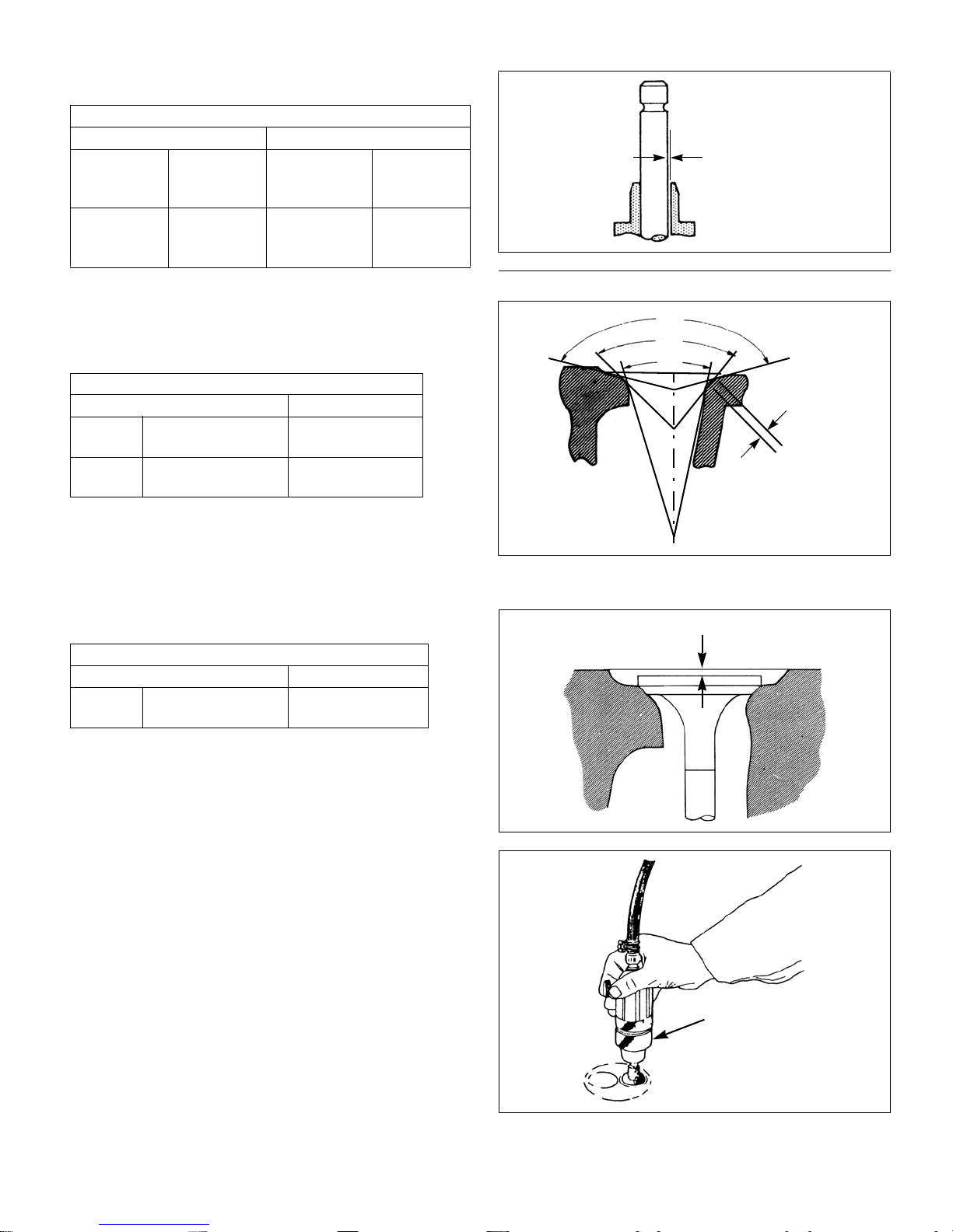
2. Valve guide and valve stem
a. Check the head and stem of each valve and
replace if burned, worn, or deformation is
excessive.
b. Measure the out side diameter at positions I, II, and
III on the valve stem with a micrometer and
replace if less than the service limit.
Wear of valve stem ø in(mm)
Intake valve Exhaust valve
Standard
assembling
value
0.274-0.2744
(6.955–6.97)
c. Replace a valve if its head thickness is less than
service limit.
Service limit Standard
assembling
value
Less than
0.2712(6.89)
0.273-0.274
(6.94–6.955)
Service limit
Less than
0.269(6.84)
Valve head thickness in(mm)
Standard assembling value Service limit
0.0305-0.0423(0.775–1.075) Less than 0.0197(0.5)
3-2 109823 2/09
d. Replace the valve if the clearance between the
Fig. 3-8
Clearance
Fig. 3-9
150°
90°
30°
Contact
Width
Fig. 3-10
Fig. 3-11
Recess
Valve
Lapper
stem and guide exceeds the service limit.
Clearance between valve stem and valve guide in(mm)
Intake valve Exhaust valve
Standard
assembling
value
0.0012-
0.0024
(0.03–0.06)
Service limit Standard
assembling
value
More than
0.0079(0.2)
0.0016-
0.0030
(0.04-0.075)
Service limit
More than
0.0100
(0.25)
3. Valve seat
a. Since the valve seat is corrected according to the
valve guide, be sure to check the valve guide for
wear condition first before correcting the seat.
Valve seat contact width in(mm)
Standard assembling value Repair value
In 0.059-0.083
(1.50-2.10)
Exhaust 0.063-0.071
(1.59-1.80)
More than
0.098(2.5)
More than
0.098(2.5)
b. Correct the seat to the standard assembling values
of the contact width and recess using seat cutters
of 15°, 45° and 75°.
c. When the seat recess exceeds the service limit,
replace the cylinder head.
Valve seat recess in(mm)
Standard assembling value Service limit
In,Ex 0.0335-0.0453
(0.85–1.15)
More than
0.0709(1.8)
d. Coat the valve seat surface with compound and
lap the contact surface turning the valve.
e. Check that the valve contact surface is within the
standard value and the contact position is even.
f. When the cylinder head is replaced with a new
head, adjust the seat contact width and seat
recess to the specified values with a seat cutter
before lapping.
109823 2/09 3-3

4. Valve spring
Fig. 3-12
Fig. 3-13
Squareness
Free Length
Replace with long block assembly
AB
Front
1
Ring Sliding Range
a. Check the valve spring visually for damage.
b. Measure the squareness of the spring using a
square on a surface plate and replace if the
service limit is exceeded.
c. Check the free length and spring force with a
spring tester and replace if the service limit is
exceeded.
Standard
Service limit
assembling
value
Squareness in(mm) 0.047(1.2) More than
0.079(2)
Free length in(mm) 1.38(35) Less than
1.3(33.5)
Spring force (when
compressed to
1.20(30.4) in(mm))
17.9 lb
(79.8
f
N){8.1 kgfp}
Less than
15.4 lb
f
N){7 kgf}
(68.6
Reassembly
Reassemble components in the reverse order of
disassembly. When assembling the valve spring, retainer
and cotter, be especially careful not to damage the valve
guide seal. Tighten the glow plu g to the proper to rque—5.6-
10.5 lb
•ft(8-15 Nm) {0.8~1.5 kgf•m}.
f
Cylinder block
Inspection and service
1. Check for cracks, damage and distortion on the top
of the block in the same way as the cylinder head.
2. Measurement of cylinder bore
a. There should be no scratches, rust, corrosion, etc.
on the cylinder bore when checked visually.
b. Measure the cylinder bore at the top, center and
bottom respectively in the crankshaft directio n (A)
and the direction at right angle to it (B). If the
repair value is exceeded, replace engine with long
block.
Distortion on cylinder block top surface in(mm)
Standard assembling value Repair value
Less than 0.0020(0.05) More than 0.0047(0.12)
Cylinder bore dia. ø in(mm)
3.0315-3.0322
More than 3.0394(77.2)
(77-77.019)
3-4 109823 2/09

Piston and piston ring
Fig. 3-14
Fig. 3-15
Snap
Ring
Piston
Pin
1
1
Fig. 3-16
Disassembly
1. Remove the piston ring using a piston ring tool.
2. Remove the snap ring and extract the piston pin.
Inspection
1. Piston
a. Check the piston for cracks, streaking and burnout
on the outside surface and replace if excessive.
b. Measure the longer diameter at 0.39in.(10 mm)
above the lower end of th e piston skirt and bore of
the cylinder in the thrust direction, calculate the
clearance, and replace if the repair value is
exceeded.
Piston skirt bottom longer dia .ø in(mm)
Standard assembling value Service limit
3.0288-3.0298
(76.9325-76.9575)
Clearance between cylinder and piston in(mm)
Standard assembling value Service limit
0.0023-0.0034
(0.0575–0.0865)
Less than
3.0197(76.7)
More than
0.0098(0.25)
c. Measure the piston pin hole diameter and piston
pin outside diameter and replace if the clearance
exceeds the service limit.
Clearance between piston pin hole and piston pin
in(mm)
Standard assembling value Service limit
-0.0000~+0.0003
(-0.000~+0.008)
More than
0.0008(0.02)
109823 2/09 3-5
 Loading...