

Page 1
The Original Engine Cooling Pump Since 1921
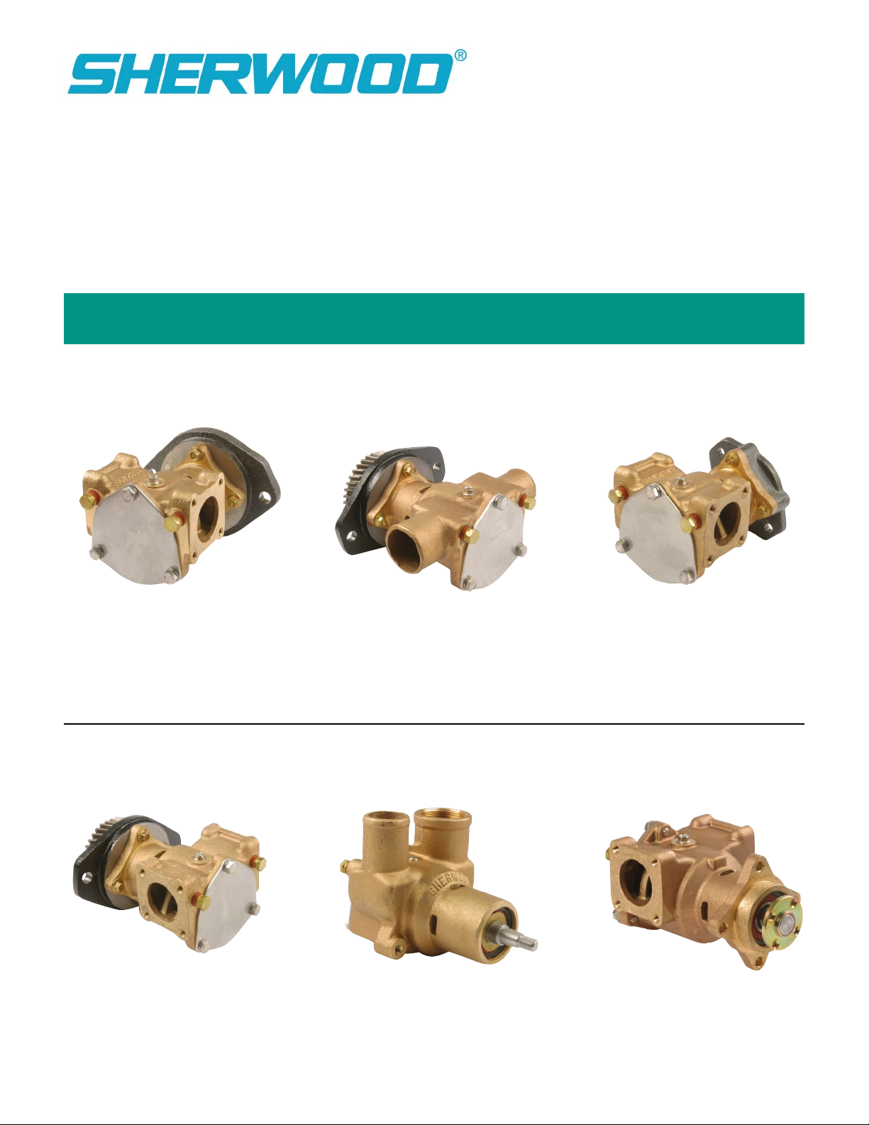
17000 and 27000 Pump Series Technical Guide
Identification
P1710X, P1710A,
P1726X, P1732X
& P1732A
P1727X, P1727A,
P1730X, P1730A, P1731,
and P1733X
P1716X, P1722X,
& P173
P176X
P1719X
P2701X
Page 2

25
24
Assembly / Disassembly Instructions
10
0
2
19
21
15
13
11
8
4
3
1
3
2
16
12
9
18
14
10
6
7
5
2
The following assembly/disassembly procedures apply to all 17000 Series pumps. Deviations from pump to pump are
primarily a result of different methods of drive and mounting. Pump model numbers can be found stamped into the
cover plate of the pump.
Disassembly:
A. Remove the three bolts (1) and lock washers (2) from the pump cover (3). The cover and o-ring (4) are now free.
The impeller end cap (5) can be pried off with a screwdriver. Normally, impellers (7) can be removed by using the
23631 impeller puller (or 3/4” – 16 bolt) for the 17000 threaded impeller, the 24412 impeller puller (or M16 x 1.5
bolt) for the 27000 threaded impeller, or by using two pair of pliers to grip two of the impeller’s vanes on opposite
sides of the impeller. A penetrating lubricant will help loosen a stuck impeller. Also, rotating the shaft by hand may
help free the impeller. The 3/16” key (6) will also be removed at this time.
B. Remove any pulleys or drive gears (25) from the drive shaft. For tapered shaft models (all models except P173,
P1719, and P2701), it is necessary to remove the shaft nut and pull the gear or pulley with a puller. For models
with pressed on gears (P173), two threaded holes are provided in the gear. An appropriate puller may be attached
to these two holes to remove the gear from the shaft. The drive hub on the P2701 pump must be removed
with a bearing puller.
C. Most models will be equipped with a flange adapter (24). The flange adapter is held to the pump body by
two socket head cap screws (21), either 3/8" or 10mm, depending on the model. The screws are removed by using
a hex socket wrench. More current models are mounted with four 8mm flange hex head bolts. The adapter is then
removed. If the lip seal (23) in the adapter requires replacing, it can be pressed out at this time.
D. The cam (8) and cam screw (9) are removed. The internal wear plate (13) will drop out. The retaining ring (10),
washer (11) and seal seat (14) are then removed.
E. From the ball bearing end, the internal snap ring (17) must be removed on models P171 through P176, and
P2701. Later models have extended bearing assemblies and are held together by means of the flanged adapter.
The shaft/bearing assembly (19) is pressed out of the body from the impeller end of the housing removed from the
engine end of the pump. The two external snap rings (10) are removed from the shaft (19) along with the bearing
washers (12), permitting removal of bearings (20).
side of the housing (18).
The mechanical seal (15) may now be pressed from the bearing
Warning: If a shaft/bearing assembly exists for the particular model that is being repaired, do not try to build the
shaft/bearing assembly from the individual parts, but instead purchase the entire assembly
. Due to extremely tight tolerances, special assembly procedures for this assembly must be followed to prevent galling and subsequent leakage
in the oil seal area of the pump.
Reassembly:
A. Press mechanical seal (15) into housing (18) with the grey silicon carbide or black carbon seal face toward the impeller.
B. On all older model pumps with mounting adapters, the lip seal (23) will have to be replaced prior to replacing the
flange adapter (24). Care should be taken to insure proper alignment of the lip seal to the adapter and that the lip seal is
uniformly pressed to prevent distortion. The metal backing ring of the lip seal goes toward the pump and away from the engine.
C. Skip this step if the entire shaft/bearing assembly is available for the particular model that is being repaired. Install external
snap ring (10) on shaft (19). Next, place washer (12), bearing (20), bearing spacer (16), second bearing (20) and washer (12)
and secure with the second external snap ring (10). The bearings will have to be pressed on from the pulley/gear end. Note
that it is extremely important to properly align the bearings to the shaft prior to press, otherwise the possibility exists of galling
the shaft in the area of the lip seal. This completes the bearing and shaft assembly.
2
Page 3

Assembly / Disassembly Instructions (continued)
D. Press the bearing and shaft assembly into the housing (18). In applicable pump models, replace the internal snap ring (17). On
newer model pumps, the bearings will be flush to the end of the housing or slightly protruding, and will be retained with the
lange adapter (24). The adapter (24) may be reassembled to the pump housing (18) at this time with the two or four bolts (21)
f
as applicable. The use of Loctite #262 or equivalent is recommended on the adapter bolts. Torque the adapter bolts to 18 ft-lbs.
. The seal seat (14) is now installed from the impeller end of the housing. The grey silicon carbide or white ceramic seat should
E
be placed against the grey silicon carbide or black carbon seal face of the mechanical seal (15). Care must be taken to remove
all burrs from the keyway to prevent cutting of the rubber cup. If possible, a half thickness key can be used to assist in
assembly. In pressing the ceramic and boot, a pusher should be used with a diameter only slightly greater than the shaft
iameter (.80"). Soapy water or a lubricant from a seal manufacturer may be used in assembly. Oil or grease must not be used
d
as it will prevent the rubber cup from properly gripping the shaft. The seat and cup are pressed just beyond the external/snap
ring groove. The seat should be inspected to insure that the cup did not become partially dislodged during the press procedure.
The washer (11) and external snap ring (10) are then installed.
F. The internal wear plate (13) is dropped in place, anti-rotation pin aligned with the cast slot in the bottom of the housing. The
cam (8) is reinstalled and secured with the cam screw (9). Older model cam screws were sealed by means of a nylon washer
requiring Permatex or other sealant to seal the cam screw. The cam screw should be inspected to insure that it does not
protrude below the cam. This condition is possible if the nylon seal is badly deformed or if a substitute screw is used. Should
the screw protrude beneath the cam, replace it with a new screw, or grind flush. Failure to do so will result in immediate
impeller damage.
G. At this time, if applicable, press on any gears (25), pulleys, or hubs onto the shaft. While pressing on the drive mechanism, the
shaft (19) must be securely supported from the impeller end and in line with the press. Failure to do so will result in either
damaged bearings and/or a canted gear with excessive run out. For the base model pumps P1716, P1722, P1727, P1730 and
P1731, replace the tapered gear and gear nut on the shaft. Use Loctite #262 on the gear threads and torque the nut to 50 ftlbs. For all other tapered gear and shaft assemblies, see the applicable engine manufacturers’ requirements for thread sealant
and torque specifications.
H. Install the impeller (7) using a non-petroleum based lubricant such as silicon or soapy water.
based fluids as they will damage the impeller. The impeller is installed using a twisting motion. Ensure the impeller blades are
bent in the same direction as upon removal. Once installed, rotate the shaft to align keyway and slide the key (6) in place. Then
cover the key hole in the impeller insert with the rubber end plug (5).
impeller will cause the key to walk out of the shaft keyway and damage the cover. The 17000 impeller requires that the key be
placed on the shaft prior to installation.
I. Replace the cover o-ring (4), cover (3), with the cover cap screws (1). Torque the cap screws to 14 ft-lbs.
replaced with a new one, record the information on the original cover to help identify the pump for future repairs and maintenance.
J. After installation, inspect the pump seal, lip seal, body, housing and cam areas for leaks.
Caution: Failure to place the plug in place on the 17000A
Note: Do not use petroleum-
Note: If the cover is
17000 Impeller Options
17000A —Impeller with threaded/thru-key insert allows for ease of installation in hard-to-reach
applications as well as easy removal. As the impeller puller is threaded in the impeller insert and
jacks against the pump shaft, the patented threaded insert allows for easy removal.
aspect of the impeller allows for the impeller to be installed prior to placing the key in the shaft keyway, therefore, making the installation process easier. (Patent No. 6,116,855)
17000K —Impeller Kit
• Kit Contains: 17000A Impeller with
17000 —Impeller only, which uses a threaded insert for ease of removal (Patent No. 6,116,855).
27000K — Impeller Kit (Patent No. 6,116,855)
• Kit Contains: 27000 splined impeller and o-ring.
threaded/thru-key insert, o-ring and rubber cap.
The thru-key
Threaded Impellers
(17000 and 27000)
Threaded Thru-Key
Design Impellers
(17000A)
3
Page 4
Assembly / Disassembly Instructions (continued)
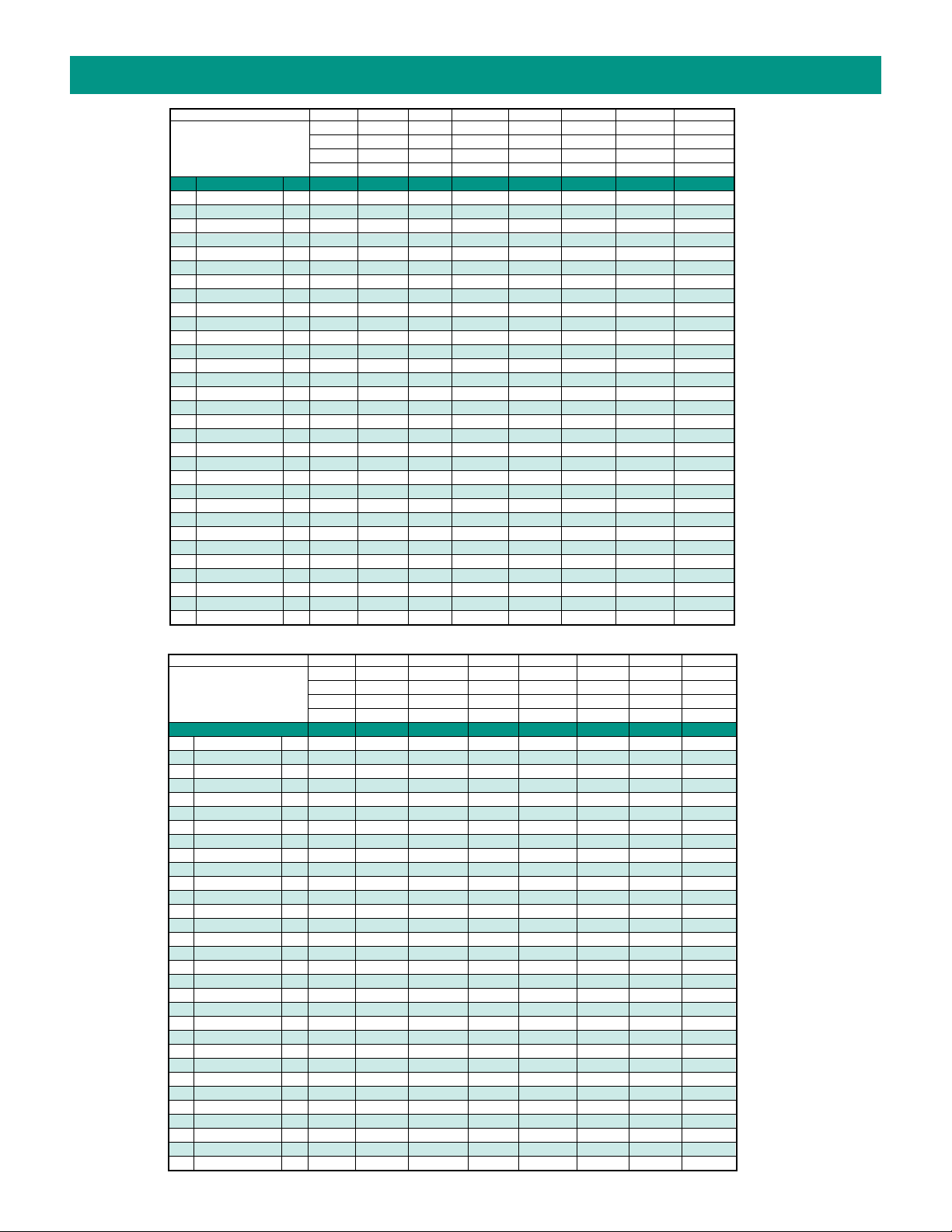
herwood # P176X P1710X P1710A P1716X P1719X P1722X P1726X P1727X
S
Item QTY
Cap Screw 3 16029 19626 19626 19626 19626 19626 19626 19626
1
Lockwasher 3 15944 15944 15944 15944 15944 15944 15944 21573
2
Cover Plate 1 18742 18742 18742 18742 18742 18742 18742 18742
3
O-ring 1 15945 15945 15945 15945 15945 15945 15945 15945
4
5 Impeller Cap 1 19210 19210 19210 19210 19210 19210 19210 19210
6 Key 1 19667 19667 19667 19667 19667 19667 19667 19667
7 Impeller 1 17000 17000 17000 17000 17000 17000 17000 17000
Cam 1 18271 18271 18271 18271 18271 18271 18271 18271
8
Cam Screw 1 10515 19714 19714 19714 19714 19714 19714 19714
9
0 Retaining Ring (Ext) 2/3 15952 15952 15952 15952 15952 15952 15952 15952
1
11 Washer 1 15959 15959 15959 15959 15959 15959 15959 15959
12 Washer 2 19614 19614 19614 19614 19614 19614 19614 19614
13 Wear Plate-Pin Assy 1 18441 18441 24162 18441 18441 18441 18441 18441
4/15 Water Seal/Seat Assy 1 15955 15955 23799 15955 15955 15955 15955 15955
1
6 Spacer 1 15940 19707 24150 19615 19615 19615 19707 19615
1
7 Retaining Ring (Int) 1 15942 15942 15942 15942
1
8 Housing 1 19015 19683 24161 19630 24409 19630 24161 24176
1
19 Shaft 1 19620 19345
19 Shaft/Bearing Assy 1 24469 24469 24470 24470 24469 24470
0 Ball Bearing 2 15951 15951
2
21 Adaptor Bolts 4 19708 19708 19708 19708 19708 19708 19708
23 Oil Lip Seal 1 21776 21776 19674 19674 19674 21776 19674
tor 1 1
4 Adap
2
25 Gear A
ssy/Hub 1 1
Cam Screw O-ring 1 19712 19712 19712 19712 19712 19712 19712
Gear Nut 1 19730 19730 19730
Adaptor Gasket 1 21570 21570 21570
Flanged Port O-rings 2 21525
Flanged Port Bolts 8
Minor Repair Kit 23973 23973 24576 23972 23972 23972 23973 23972
Major Repair Kit 23975 23975 24577 23974 23974 23974 23975 23974
* Denotes pump used 23799 mechanical seal
176 P1710 P1716B-01 P1719 P1722B-01 P1726 P1727FB
P
176-02* P1710-02* P1716B-02* P1719-01 P1722B-02* P1727FB-01
P
9699 19699 1
P1719F-01 P1727FB-02*
9727 19700 19955 19699 21205
9885 19885 1
9885
Sherwood # P1727A P1730X P1730A P1731 P1732X P1732A P1733X P2701X
Item QTY
1 Cap Screw 3 19626 19626 19626 19626 19626 19626 19626 19626
2 Lockwasher 3 21573 21573 21573 21573 15944 15944 15944 21573
3 Cover Plate 1 18742 18742 18742 18742 18742 18742 18742 18742
4 O-ring 1 15945 15945 15945 15945 15945 15945 15945 15945
5
6
7
8
9
10
11
12
13
14/15
16
17
18
19 Shaft 1 24015
19 Shaft/Bearing Assy 1 24470 24470 24470 24470 24469 24469 24306
20 Ball Bearing 2 15951
21 Adaptor Bolts 4 19708 19708 19708 19708 19708 19708 19708
23 Oil Lip Seal 1 24250 19674 24250 19674 21776 21776 24017
24 Adaptor 1 21205 21985 21985 21985 19699 19699 24016
4
p 1 19210 19210 19210 19210 19210 19210 19210 19210
Impeller Ca
Key 1 19667 19667 19667 19667 19667 19667 19667
Impeller 1 17000 17000 17000 17000 17000 17000 17000 27000
Cam 1 18271 18271 18271 18271 21318 21318 18271 18271
Cam Screw 1 19714 19714 19714 19714 19714 19714 19714 19714
Retaining Ring (Ext) 2/3 15952 15952 15952 15952 15952 15952 15952 15952
Washer 1 15959 15959 15959 15959 15959 15959 15959 15959
Washer 2 19614 19614 19614 19614 19614 19614 19614
Wear Plate-Pin Assy 1 24162 18441 24162 18441 18441 24162 18441 24162
Water Seal/Seat Assy 1 23799 15955 23799 15955 23799 23799 15955 23799
Spacer 1 24222 19615 24222 19615 19707 24150 24014 24150
Retaining Ring (Int) 1 15942 15942
Housing 1 24176 24176 24176 24176 24161 24161 24409 24176
Gear Assy/Hub 1 19885 22495 22495 24144
Cam Screw O-ring 1 19712 19712 19712 19712 19712 19712 19712 19712
Gear Nut 1 19730 19730 19730 19730 19730 19730
Adaptor Gasket 1 21570 21570 21570
Flanged Port O-rings 2 21525 21525 21525 21525 21525 21525 21525 21525
Flanged Port Bolts 8 21484 21484 21484 21484 21484 21484
Minor Repair Kit 24578 23972 24578 23972 23973 24576 23972 24580
Major Repair Kit 24579 23974 24579 23974 23975 24577 23974 24581
* Denotes pump used 23799 mechanical seal
P1730-01 P1731-01 P1732-01 P1733F-01 P2701-01
P1730-02* P1731F-02* P1732-02
P1730F-01
P1730F-02*
Page 5

Preventative Maintenance
The #1 reason for premature engine wear is overheating. To maintain engine performance,
insist upon genuine Sherwood impellers and service kits.
Pleasure Boating Commercial/Fishing Use
Low Hours) (High Hours)
Maintenance
Schedule Light Duty Severe Duty Heavy Duty Severe Duty
Impeller Kit
Every year 6 months 6 months 3 months
Minor Kit 2 years Every year Every year 6 months
Major Kit 4 years 2 years 2 years Every year
Impeller Impeller Minor Minor Minor Minor Minor Major Major Major Major Major
Kit Kit Kit Kit Kit Kit Kit Kit Kit Kit Kit Kit
17000K 27000K 23972 23973 24576 24578 24580 23974 23975 24577 24579 24581
P176X X X X
P1710X X X X
P1710A X X X
P1716X X X X
P1719X X X X
P1722X X X X
P1726X X X X
P1727X XX X
P1727A X X X
P1730X XX X
P1730A X X X
P1731
P1732X X X X
P1732A
P1733X
P2701X X X X
X
X
X
(
(High RPM, Silt or Sand) (High RPM, Silt or Sand)
XX
XX
X
5
Page 6

Inspection
The #1 reason for premature engine wear is overheating.
To maintain engine performance, insist upon genuine Sherwood impellers and service kits.
Recommended inspection to be performed at any service interval:
Impeller . . . . . . . . . . Inspect for cracks or tears. Also, inspect for excessive abrasion of vane ends. Replace annual-
ly or if any of the conditions exist, as in the picture below.*
Wear Plate . . . . . . . . Inspect for wear, flatness, and pin for fatigue. Replace at minor and major pump rebuild or if
wear is evident to maintain pump flow and suction performance.
Cam . . . . . . . . . . . . . Replace at major pump rebuild or if pitting/wear is evident.
Cover . . . . . . . . . . . . Replace at major pump rebuild or if wear exists to
maintain pump flow and suction performance.
Mechanical Seal . . . . Replace at minor and major pump rebuild or if leaking.
Lip Seal . . . . . . . . . . . Replace at minor and major pump rebuild or if leaking.
Shaft . . . . . . . . . . . . . Inspect for wear in area of lip seal and rubber impeller.
Grooving of lip seal area or heavy fretting of the
impeller end shaft will require shaft replacement.
Bead worn
to flat
Ripped
Vane
Pitting
Tear
Cavitation
Bearing . . . . . . . . . . . Inspect for loss of grease, corrosion or rough rotation.
Replace at major pump rebuild or if in doubt.
Bowed (set)
Genuine Sherwood Tech Tips
Sherwood recommends replacing your impeller annually. Proper storage of the impellers during a prolonged
lay-up can help maintain the life of the impeller.
Remove the impeller from the housing and store it in a cool, dark place. This will avoid the following:
• Copper bonding of the impeller to the housing
• Vanes “setting” into position as stored in the housing
• Ultraviolet deterioration
Three tips to help you install your new Sherwood impeller:
• Use a non-petroleum based lubricant (silicon or soapy water) to help slide the impeller into the housing.
• Install the impeller with a twisting motion onto the shaft. Never force an impeller onto the shaft.
• Impeller must be able to move freely on the shaft to properly prime and function.
(Use a small amount of non-petroleum based lubricant to help hold the o-ring when replacing the cover.)
See Maintenance Schedule
*
 Loading...