

Page 1
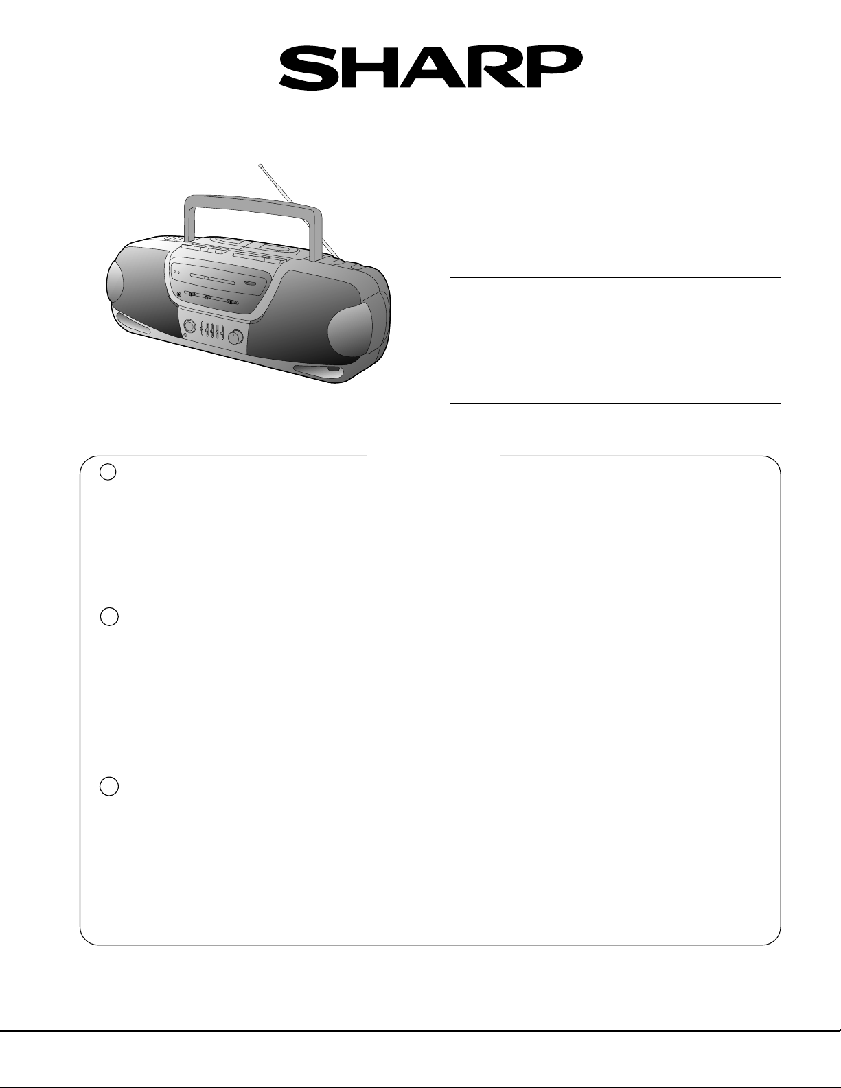
WQ-730H
SERVICE MANUAL/SERVICE-ANLEITUNG/MANUEL DE SERVICE
No. SX672WQ730HBK
WQ-730H(BK)
• In the interests of user-safety the set should be restored to its
original condition and only parts identical to those specified
should be used.
• Im Interesse der Benutzer-Sicherheit sollte dieses Gerät wieder
auf seinen ursprünglichen Zustand eingestellt und nur die
vorgeschriebenen Teile verwendet werden.
• Dans l’intérêt de la sécurité de l’utilisateur, l’appareil devra être
reconstitué dans sa condition première et seules des pièces
identiques à celles spécifiées, doivent être utilisées.
E
IMPORTANT SERVICE NOTES (FOR UK ONLY) ....... 2
SPECIFICATIONS ........................................................ 2
NAMES OF PARTS ...................................................... 4
FITTING OF DIAL POINTER ........................................ 4
DISASSEMBLY............................................................. 6
ADJUSTMENT .............................................................. 8
D
TECHNISCHE DATEN.................................................. 2
BEZEICHNUNG DER TEILE ........................................ 4
ANBRINGEN DES SKALENZEIGERS ......................... 4
ZERLEGEN................................................................... 6
EINSTELLUNG ............................................................. 8
F
CARACTÉRISTIQUES.................................................. 2
NOMENCLATURE ........................................................ 4
FIXATION DE L’AIGUILLE ........................................... 4
DÉMONTAGE ............................................................... 6
RÉGLAGE..................................................................... 8
INHALTSVERZEICHNIS
TABLE DES MATIÈRES
Page
Seite
Page
CONTENTS
Page
NOTES ON SCHEMATIC DIAGRAM ......................... 11
SCHEMATIC DIAGRAM / WIRING
SIDE OF P.W.BOARD ............................................... 12
PACKING METHOD (FOR UK ONLY)........................ 16
REPLACEMENT PARTS LIST/EXPLODED VIEW
Seite
ANMERKUNGEN ZUM SCHEMATISCHEN
SCHALTPLAN............................................................ 11
SCHEMATISCHER SCHALTPLAN/
VERDRAHTUNGSSEITE DER LEITERPLATTE....... 12
ERSATZTEILLISTE /EXPLOSIONSDARSTELLUNG
Page
REMARQUES CONCERNANT LE DIAGRAMME
SCHÉMATIQUE......................................................... 11
DIAGRAMME SCHÉMATIQUE/CÔTÉ CÂBLAGE DE
LA PLAQUETTE DE MONTAGE IMPRIMÉ............... 12
LISTE DES PIÈCES DE RECHANGE /VUE EN ÉCLATE
SHARP CORPORATION
– 1 –
Page 2
WQ-730H
OUT
WITHSTANDING
VOLTAGE TESTER
SHORT-CIRCUIT
AC POWER
SUPPLY CORD
CONNECT THE PROBE
TO GND OF BATTERY
TERMINAL
+
–
AC
UNIT
PROBE
E
FOR A COMPLETE DESCRIPTION OF THE OPERATION OF THIS UNIT, PLEASE REFER
TO THE OPERATION MANUAL.
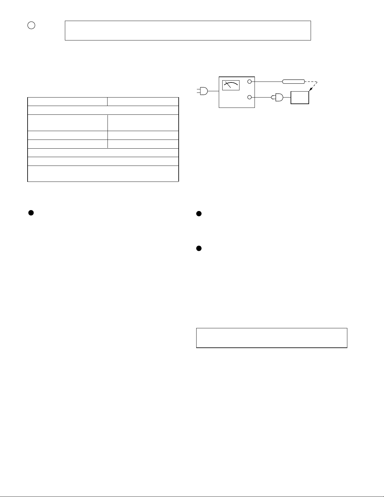
IMPORTANT SERVICE NOTES (FOR UK ONLY)
Before returning the unit to the customer after completion of
a repair or adjustment it is necessary for the following withstand voltage test to be applied to ensure the unit is safe for
the customer to use.
Setting of Withstanding Voltage Tester and set.
Set name set value
Withstanding Voltage Tester
Test voltage 4,240 VPEAK
3,000 VRMS
Set time 6 secs
Set current(Cutoff current) 4 mA
Unit
Judgment
OK: The “GOOD” lamp lights.
NG: The “NG” lamp lights and the buzzor sounds.
SPECIFICATIONS
General
Power source: AC 220-230 V, 50 Hz
DC 12 V ["D" size (UM/SUM-1,R20
or HP-2) battery x 8]
Power consumption: 30 W
Output power: PMPO; 60 W (30 W + 30 W)
(AC operation)
MPO (Max.); 20 W (10W + 10 W)
(AC operation)
RMS; 10 W (5 W + 5 W)
(DC operation, DIN 45 324)
Speakers: 12 cm (4-3/4") free-edge
woofer x 2
5 cm (2") surround speaker x 2
Optput terminal: Headphones; 16-50 ohms
(recommended; 32 ohms)
Dimensions: Widh; 600 mm (23-5/8")
Height; 195 mm (7-11/16")
Depth; 190 mm (7-1/2")
Weight: 4.3 kg (9.5 lbs.) without batteries
Radio section
Frequency range: FM; 87.5 - 108 MHz
MW; 526.5 - 1,606.5 kHz
LW; 148.5 - 283.5 kHz
Tape recoder section
Frequency rasponse: 60 - 12,000 Hz (Normal tape)
Signal/noise rario: 40 dB (TAPE 1, recording/
playback)
55 dB (TAPE 2, playback)
Wow and flutter: 0.15 % (DIN 45 511)
Motor: DC 12 V electric governor
Bias system: AC bias
Erase system: Magnet earse
Specifications for this model are subject to change without
prior notice.
– 2 –
Page 3

WQ-730H
D
EINE VOLLSTÄNDIGE BESCHREIBUNG DER BEDIENUNG DIESES GERÄTES IST IN DER BEDIENUNGSANLEITUNG ENTHALTEN.
TECHNISCHE DATEN CARACTÉRISTIQUES
Allgemeines
Spannungsversorgung: Netzspannung 220-230 V, 50 Hz
Gleichspannung 12 V [Batterie in
Größe "D" (UM/SUM-1,R20 oder
HP-2) x 8]
Leistungsaufnahme: 30 W
Ausgangsleistung: Spitzenmusikleistung; 60 W
(30 W + 30 W) (Netzbetrieb)
Musikleistung (max.); 20 W
(10W + 10 W) (Netzbetrieb)
Sinusleistung; 10 W (5 W + 5 W)
(Gleichspannungsbetrieb, DIN 45
324)
Lautsprecher: Randloser 12 cm-Tieftöner x 2
5 cm Surround-Lautsprecher x 2
Ausgang: Kopfhörer; 16-50 Ohm
(empfohlen; 32 Ohm)
Abmessungen: Breite; 600 mm
Höhe; 195 mm
Tiefe; 190 mm
Gewicht: 4,3 kg ohne Batterien
Radio-Teil
Frequenzbereich: UKW; 87,5 - 108 MHz
MW; 526,5 - 1.606,5 kHz
LW; 148,5 - 283,5 kHz
Tonbandrecorder-Teil
Frequenzgang: 60 - 12.000 Hz (Normalband)
Rauschabstand: 40 dB (TAPE 1, Aufnahme/
Wiedergabe)
55 dB (TAPE 2, Wiedergabe)
Gleichlaufschwankungen: 0,15 % (DIN 45 511)
Motor: Elektrischer Regler für 12 V
Gleichspannung
Vormagnetisierungssystem: Wechselspannungsvormagneti-
sierung
Löschsystem: Magnetische Löschung
F
POUR LA DESCRIPTION COMPLÉTE DU FONCTIONNEMENT DE CET APPAREIL, SE REPORTER AU MODE
D'EMPLOI.
Général
Alimentation: 220-230 V CA, 50 Hz
12 V CC [Pile "D" (UM/SUM-1,R20
ou HP-2) x 8]
Consommation: 30 W
Puissance de sortie: PMPO; 60 W (30 W + 30 W)
(fonctionnement sur CA)
MPO (maxi); 20 W (10W + 10 W)
(fonctionnement sur CA)
RMS; 10 W (5 W + 5 W)
(fonctionnement sur CC, DIN 45
324)
Haut-parleurs: Woofer à bords libres de 12 cm x 2
Haut-parleur surround de 5 cm x 2
Borne de sortie: Casque; 16-50 ohms
(recommandé; 32 ohms)
Dimensions: Largeur; 600 mm
Hauteur; 195 mm
Profondeur; 190 mm
Poids: 4,3 kg sans piles
Radio
Gamme de fréquences: FM; 87,5 - 108 MHz
PO; 526,5 - 1.606,5 kHz
GO; 148,5 - 283,5 kHz
Magnétophone à cassette
Réponse en fréquence: 60 - 12.000 Hz (Bande normale)
Rapport signal/bruit: 40 dB (TAPE 1, enregistrement/
lecture)
55 dB (TAPE 2, lecture)
Pleurage et
scintillement: 0,15 % (DIN 45 511)
Moteur: Régulateur électrique de 12 V CC
Système de
polarisation: Polarisation CA
Système d'effacement: Effacement magnétique
Dietechnischen Daten für dieses Modell können ohne
vorherige Ankündigung Änderungen unterworfen sein.
Les caractéristiques de ce modèle sont sujettes à modification sans préavis.
– 3 –
Page 4
WQ-730H
E
14 16
13 15
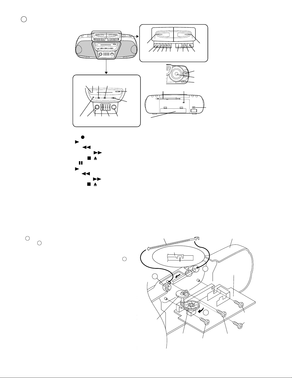
NAMES OF PARTS
2120 2219 2423
1. (TAPE 1) Cassette Compartment
2. (TAPE 1) Record Button:
3. (TAPE 1) Play Button:
4. (TAPE 1) Rewind Button:
5. (TAPE 1) Fast Forward Button:
6. (TAPE 1) Stop/Eject Button:
7. (TAPE 1) Pause Button:
8. (TAPE 2) Play Button:
9. (TAPE 2) Rewind Button:
10. (TAPE 2) Fast Forward Button:
11. (TAPE 2) Stop/Eject Button:
12. (TAPE 2) Cassette Compartment
13. Power Indicator
14. FM Stereo Indicator
15. Dubbing Speed/Built-in Microphone/FM Mode
Switch
/
/
17
18
1
12
2 3 4 5 6 7 8 9 10 11
25
26
27
28
29
31
16. Function Selector Switch
17. Tuning Control
18. Band Selector Switch
19. Headphone Socket
20. Surround Switch
21. Built-in Microphone
22. Extra Bass Control: X-BASS
23. Graphic Equalizer Controls
24. Volume Control
25. Surround Speaker
26. Woofer
27. Bass Reflex Duct
28. FM/SW Telescopic Rod Arial
29. Beat Cancel Switch
30. AC Power Input Socket
31. Battery Compartment
30
FITTING OF DIAL POINTER
1. Remove the main PWB. Attach the dial pointer as shown arrow
A on the front cabinet, putting it into the section indicated by
A
B
arrow .
2. Install the main PWB in the front cabinet and secure it with the
four screws.
3. Turn the dial drum in the direction indicated by arrow . Set
the dial pointer to point "0", and then make the rest of the
adjustments.
C
Dial Pointer (221)
Dial Pointer (221)
B
Tuning
Control
Knob (223)
''0''Point
Dial Drum
(220)
A
C
Screw(609)
ø3 x8mm
Figure 4
Front Cabinet
Main PWB
Screw(609)
ø3 x8mm
Screw(608)
ø2.6 x8mm
– 4 –
Page 5

WQ-730H
BEZEICHNUNG DER TEILE
D
1. (TAPE 1) Cassettenfach
2. (TAPE 1) Aufnahmetaste:
3. (TAPE 1) Wiedergabetaste:
4. (TAPE 1) Rückspultaste:
5. (TAPE 1) Schnellvorlauftaste:
6. (TAPE 1) Stopp-/Auswurftaste:
7. (TAPE 1) Pausentaste:
8. (TAPE 2) Wiedergabetaste:
9. (TAPE 2) Rückspultaste:
10. (TAPE 2) Schnellvorlauftaste:
11. (TAPE 2) Stopp-/Auswurftaste:
12. (TAPE 2) Cassettenfach
13. Einschaltanzeige
14. UKW-Stereoanzeige
15. Schalter für Überspielgeschwindigkeit/Eingebautes
Mikrofon/UKW-Betriebsart
16. Funktionswahlschalter
17. Abstimmregler
18. Wellenbereichswahlschalter
19. Kopfhörerbuchse
20. Sorround-Schalter
21. Eingebautes Mikrofon
22. Extratieftonregler: X-BASS
23. Regler des graphischen Equalizers
24. Lautstärkeregler
25. Surround-Lautsprecher
26. Tieftöner
27. Baßreflexkanal
28. UKW/KW-Teleskopantenne
29. Schwebungsunterdrückungsschalter
30. Netzeingangsbuchse
31. Batterifach
/
/
F
1. (TAPE 1) Compartiment de cassette
2. (TAPE 1) Touche d'enregistrement:
3. (TAPE 1) Touche de lecture:
4. (TAPE 1) Touche de rebobinage:
5. (TAPE 1) Touche d'avance rapide:
6. (TAPE 1) Touche d'arrêt/éjection:
7. (TAPE 1) Touche de pause:
8. (TAPE 2) Touche de lecture:
9. (TAPE 2) Touche de rebobinage:
10. (TAPE 2) Touche d'avance rapide:
11. (TAPE 2) Touche d'arrêt/éjection:
12. (TAPE 2) Compartiment de cassette
13. Voyant d'alimentation
14. Voyant de FM stéréo
15. Commutateur de vitesse de copie/microphone
incorporé/mode FM
16. Sélecteur de fonction
17. Commande d'accord
18. Sélecteur de gamme d'ondes
19. Prise de caque
20. Commuteur surround
21. Microphone incorporé
22. Commande des extra-graves: X-BASS
23. Commandes de l'égaliseur graphique
24. Commande de volume
25. Enceinte surround
26. Woofer
27. Évent de baffle réflex
28. Antenne télescopique FM/OC
29. Commutateur antibattement
30. Prise d'entrée secteur
31. Logement de piles
NOMECLATURE
/
/
ANBRINGEN
DES SKALENZEIGERS
1. Die Hauptleiterplatte entfernen. Den Skalenzeiger wie
durch Pfeil gezeigt an den Gehäusevorderteil anbringen, indem er in den durch Pfeil angezeigten Teil gesetzt
wird.
2. Die Hauptleiterplatte in den Gehäusevorderteil einbauen
und mit zwei Schrauben sichern.
3. Die Skalentrommel in Pfeilrichtung drehen. Den Skalenzeiger auf “0” stellen, und dann sonstige Einstellungen
durchführen.
A
B
C
FIXATION DE L´AIGUILLE
1. Retirer la PMI principale. Attacher l’index au coffret frontal
comme l’indique la flèche , en l’introduisant dans la partie
indiquée par les flèches .
2. Mettre la PMI principale dans le coffret frontal et fixer la PMI
avec deux vis.
3. Tourner le tambour de cadran dans le sens indiqué par la
C
flèche . Régler l’index sur le point “0” et puis effectuer les
autres ajustements.
A
B
– 5 –
Page 6

WQ-730H
Main
PWB
(A5) x1
(A2) x6
ø3 x20mm
(A3) x2
ø3 x12mm
(A4) x1
ø3 x10mm
(A1) x1
Front Cabinet
Rear Cabinet
Main
PWB
(A6) x1
(B2) x1
ø3 x10mm
(B2) x1
ø3 x10mm
(B3) x6
ø3 x10mm
Main
PWB
(B1) x2
(B1) x1
Front Cabinet
Tape
Mechanism
Cassette Holder
(Left/Right)
Open
Open
E
Caution on Disassembly
Follow the below-mentioned notes when disassembling
the unit and reassembling it, to keep it safe and ensure
excellent performance:
1. Take cassette tape out of the unit.
2. Be sure to remove the power supply plug from the wall
outlet before starting to disassemble the unit and remove
the batteries from the unit.
3. Take off nylon bands or wire holders where they need
be removed when disassembling the unit. After servicing
the unit, be sure to rearrange the leads where they were
before disassembling.
4. Take sufficient care on static electricity of integrated
circuits and other circuits when servicing.
STEP REMOVAL PROCEDURE FIGURE
1 Front Cabinet/ 1. Battery Compartment .....
Rear Cabinet Lid........................(A1)x1 6-1
2. Screw ................... (A2)x6
3. Screw ................... (A3)x2
4. Screw ................... (A4)x1
5. Socket .................. (A5)x1
6. Tip ........................(A6)x1
2 Tape Mechanism 1. Socket .................. (B1)x3 6-2
2. Screw ................... (B2)x2
3. Open the cassette holder.
4. Screw ................... (B3)x6
3 LED PWB 1. Socket ..................(C1)x1 6-3
4 Main PWB 1. Socket ..................(D1)x5 6-3
2. Screw ...................(D2)x3
3. Screw ...................(D3)x1
5 Surround PWB/ 1. Screw ................... (E1)x1 6-4
LED PWB 2. Bracket .................(E2)x2
6 Graphic Equalizer 1. Knob..................... (F1)x1 6-4
PWB 2. Knob holder.......... (F2)x1
3. Screw ................... (F3)x4
4. Shield Paper ........ (F4)x1
DISASSEMBLY
Figure 6-1
Graphic
Equalizer
PWB
(F3) x4
ø3 x10mm
(E1) x1
ø3 x8mm
Front Cabinet
(F4) x1
Surround
PWB
Figure 6-4
(F1) x1
(F2) x1
LED PWB
(E2) x1
– 6 –
(D3) x1
ø2.6 x8mm
(D2) x3
ø3 x8mm
(D1) x4
Figure 6-2
Front Cabinet
Main
PWB
Figure 6-3
Hook
LED PWB
(C1) x1
(D1) x1
Page 7
WQ-730H
D
Vorsichtsmaßregeln für das Zerlegen
Beim Zerlegen und Zusammenbauen des Gerätes die
folgenden Anweisungen befolgen, um dessen
Betriebssicherheit und ausgezeichnete Leistung
aufrechtzuerhalten.
1. Cassettenband aus dem Gerät herausnehmen.
2. Bevor mit dem Zerlegen des Gerätes begonnen wird,
unbedingt den Netzstecker aus der Wandsteckdose
ziehen und die Batterien aus dem Gerät entfernen.
3. Nylonbänder oder Leitungshalter entfernen, falls dies
beim Zerlegen des Gerätes erforderlich ist. Nach Warten
des Gerätes darauf achten, die Leitungen wieder so zu
verlegen, wie sie vor den Zerlegen angeordnet waren.
4. Beim Warten auf statische Elektrizität der integrierten
Schaltkreise und andere Schaltungen achten.
SCH-
RITT
ENTFERNEN
1 Gehäusehintertei/ 1. Batteriefachdeckel.. (A1)x1 6-1
Gehäusevorderteil 2. Schraube ................ (A2)x6
2 Band 1. Buchse.................... (B1)x3 6-2
mechanismus 2. Schraube ................(B2)x2
3 LED-Leiterplatte 1. Buchse....................(C1)x1 6-3
4 Hauptleitplatte 1. Buchse....................(D1)x5 6-3
5 Surroundplatte/ 1. Schraube ................(E1)x1 6-4
LED-Leiterplatte 2. Halterung ................(E2)x2
6 Frequenzgangent- 1. Knopf.......................(F1)x1 6-4
Zerrer-Leiterplatte 2. Knopfhalter .............(F2)x1
VERFAHREN
3. Schraube ................(A3)x2
4. Schraube ................(A4)x1
5. Buchse.................... (A5)x1
6. Spitze ......................(A6)x1
3. Das Cassettenfach öffnen.
4. Schraube ................(B3)x6
2. Schraube ................(D2)x3
3. Schraube ................(D3)x1
3. Schraube ................(F3)x4
4. Abschirmpapier ......(F4)x1
ABBIL-
DUNG
F
DÉMONTAGEZERLEGEN
Précautions pour le démontage
Lors du démontage de l’appareil et de son remontage,
suivre les précautions ci-dessous, pour maintenir la sécurité
et d’excellentes performances.
1. Enlever la cassette de l’unité.
2. S’assurer de retirer la fiche d’alimentation secteur de la
prise murale avant de démarrer le démontage de
l’appareil et déposer les piles de l’appareil.
3. Déposer les bandes de nylon ou les serre-câbles si
nécessaire lors du démontage de l’appareil. Après la
réparation de l’appareil, s’assurer de redisposer les fils
tel qu’ils étaient avant le démontage.
4. Faire attention à l’électricité statique des circuits intégrés
et des autres circuits lors de la réparation.
ÉTAPE
1 Coffret arrière/ 1. Couvercle de logement
2 Mécanisme 1. Douille ................ (B1)x3 6-2
3 PMI de LED 1. Douille ................ (C1)x1 6-3
4 PMI principale 1. Douille ................ (D1)x5 6-3
5 PMI surround/ 1. Vis ......................(E1)x1 6-4
6 PMI de l'egaliseur 1. Bouton................(F1)x1 6-4
DÉPOSE PROCÉDÉ
Coffret avant de piles.............. (A1)x1 6-1
2. Vis ......................(A2)x6
3. Vis ......................(A3)x2
4. Vis ......................(A4)x1
5. Douille ................ (A5)x1
6. Bout ....................(A6)x1
casstte 2. Vis ......................(B2)x2
3. Ouvrir le porte-cassette.
4. Vis ......................(B3)x6
2. Vis ......................(D2)x3
3. Vis ......................(D3)x1
PMI de LED 2. Support............... (E2)x2
graphique 2. Porte-bouton ...... (F2)x1
3. Vis ......................(F3)x4
4. Papier de
blindage ............ (F4)x1
FIGURE
– 7 –
Page 8
WQ-730H
E
ADJUSTMENT
MECHANISM SECTION
• Driving Force Check
Torque Meter
Play: TW-2412 Tape 1: Over 50g
Specified Value
Tape 2: Over 60 g
• Torque Check
Torque Meter
Play: TW-2111 30 to 60 g.cm 30 to 60 g.cm
Fast forward: TW-2231 55 to 120 g.cm 80 to 135 g.cm
Rewind: TW-2231 55 to 120 g.cm 80 to 135 g.cm
Specified Value
Tape 1 Tape 2
• Head Azimuth
Test Tape
MTT-114 Headphones Socket
Instrument Connection
(Load resistance: 32 ohms)
• Tape Speed (Normal only)
Test Tape
Adjusting
Point
Specified
Value
MTT-111 Tape 1,2: VR501 3,000 ± 60 Hz Headphones
Instrument
Connection
socket(Load
resistance:
32 ohms)
TAPE SECTION
Position of each switch or control
Volume control Max
Beat cancel A
Function/Power Tape/Stand-by
Dubbing speed/Built-in Microphone Normal/Mic Off
• Bias Oscillation Frequency
Specified Value
Beat cancel A: 100 ± 4 kHz
B: 94 ± 4 kHz
C: 104 ± 4 kHz
• Playback Amplifier Sensitivity Check
Test Tape
MTT-118 1.3 V ± 3 dB Speaker terminal
Specified Value
Instrument Connection
(Load resistance: 3 ohms)
TUNER SECTION
fL: Low-range frequency
fH: High-range frequency
• AM IF/RF
Test Stage
Value/Adjusting
Point
IF T3
MW Band fL: L6
Coverage fH: TC8
MW Tracking fL (600 kHz): L3 (MW)
fH (1,400 kHz): TC7
LW Band fL: L7
Coverage fH: TC4
LW Tracking fL (170 kHz): L4 (LW)
fH (270 kHz): TC2
• FM IF/RF
Specified
Specified
Test Stage
Value/Adjusting
Point
IF T1
Detection T2
Band Coverage fL: L2
fH: TC6
Tracking fL (88.0 MHz): L1
fH (108.0 MHz): TC5
• VCO Frequency
Specified ValueTest Stage
VR1 76 kHz ± 200 Hz Pin 13 of IC2
Instrument
Connection
Input: Antenna
Output: Pin 3 of IC2
Input: Antenna
Output: Headphones
Socket
(Load resistance:
32 ohms)
Instrument
Connection
Input: Antenna
Output: Pin 17 of IC2
Input: Antenna
Output: Headphones
Socket
(Load resistance:
32 ohms)
Instrument
Connection
VR501
CNP501
VCO
LW
TRACKING
TAPE SPEED
FM
AM IF
T3
3
12 1
IC2
17
13 24
FM DETECTION
VR1
T2
fH
fL
TRACKING
L3
MW
TC2
MW
TRACKING
fLfH
FM IF
T1
124
IC1
L2
L1
TC6
TC8
TC5
TC4
TC7
fH
fL
Figure 8 ADJUSTMENT POINTS
– 8 –
L6
L7
MAIN PWB
L4
LW
fH
FM BAND
COVERAGE
fL
fH
LW BAND
COVERAGE
fL
MW BAND
fL
COVERAGE
MW BAND
fH
COVERAGE
Page 9

WQ-730H
D
EINSTELLUNG
MECHANISMUS-TEIL TUNER-TEIL
• Überprüfung der Antriebskraft
Drehmomentmesser Vorgeschriebener Wert
Wiedergabe: TW-2412 Band1: über 50 g
Band 2: über 60 g
• Überprüfung des Drehmoments
Drehmomentmesser
Wiedergabe: TW-2111 30 – 60 g.cm 30 – 60 g.cm
Schnellvorlauf: TW-2231 55 – 120 g.cm 80 – 135 g.cm
Rückspulung: TW-2231 55 – 120 g.cm 80 – 135 g.cm
Vorgeschriebener Wert
Band 1 Band 2
• Kofazimut
InstrumentenanschlußTestband
MTT-114 Kophöerbuchse
(Belastungswiderstand: 32 Ohm)
• Bandgeschwindigkeit
Testband Einstell-
punkt
MTT-111 Band 1,2: 3.000 ± 60 Hz Kophörer-
VR501 buchse
Vorgeschrie-
bener Wert
Instrumente-
nanschluß
(Belastungswiderstand:
32 Ohm)
DECK-TEIL
Stellung jedes schalters oder stellers
Lautstärkeregler Max
Schwebungsunterdrückungsschalter A
Funktionsschalter Band/Stand-by
Überspielgeschwindigkeit/Eigebautes Normale/Off
• ÜberprüfungderVormagnetisierungs
Schawingungsfrequenz
Vorgeschriebener Wert
Unterdrückung von A: 100 ± 4 kHz
Interferenzpfeifen B: 94 ± 4 kHz
C: 104 ± 4 kHz
• Überprüfung der Empfindlichkeit des
Wiedergabe-Verstärkers
Testband Instrumentenanschluß
MTT-118 1,3 ± 3 dB Lautsprecherklemme
Vorgeschriebener
Wert
(Belastungswiderstand:
3 Ohm)
fL: Niedriger Frequenzbereich
fH: Hoher Frequenzbereich
• MW-Zwischen-/Hochfrequenz
Prüfstufe
ZF T3
MW-Frequenz- fL: L6
bereich fH: TC8
MW-Abtastung fL (600 kHz): L3 (MW)
fH (1.400 kHz): TC7
LW-Frequenz- fL: L7
bereich fH: TC4
LW-Abtastung fL (170 kHz): L4 (LW)
fH (270 kHz): TC2
• UKW-Zwischen-/Hochfrequenz
Prüfstufe Instrumentenan-
ZF T1
Demodulation T2
Frequenz- fL: L2
bereich fH: TC6
Abtastung fL (88,0 MHz): L1
fH (108,0 MHz):TC5
•
Frequenz des spannungsgesteuerten Oszillators
Einstellpunkt Vorgeschriebener
VR1 76 kHz ± 200 Hz Stift 13 von IC2
DIE ANWEISUNG DER FREQUENZEINSTELLUNG
Um der Postverfügung Nr. 478/1981 zu entsprechen, wird
der UKW-Frequenzbereich mit Hilfe der Oszillatorspule
(L2-unntere Eckfrequenz: 87,5 MHz) und des Osz
illatortrimmers (TC6-obere Eckfrequenz: 108,0 MHz)
eingestellt.
Vorgeschriebener
Wert/
Einstellpunkt
Vorgeschriebener
Wert/
Wert
Instrumentenan-
schluß
Eingang: Antenne
Ausgang: Stift 3 von IC2
Eingang: Antenne
Ausgang: Kophöerbuchse
(Belastungswiderstand:
32 Ohm)
schluß
Eingang: Antenne
Ausgang: Stift 17 von IC2
Eingang: Antenne
Ausgang: Kophöerbuchse
(Belastungswiderstand:
32 Ohm)
Instrumentenan-
schluß
– 9 –
Page 10

WQ-730H
F
PARTIE MECANISME
• Vérification de la force d'entraînement
Torsiomètre
Lecture: TW-2412 Bande 1: Plus de 50 g
• Vérification du couple
Torsiomètre
Lecture: TW-2111 30 à 60 g.cm 30 à 60 g.cm
Avance rapide: TW-2231 55 à 120 g.cm 80 à 135 g.cm
Rebobinage: TW-2231 55 à 120 g.cm 80 à 135 g.cm
• Azimut de la tête
Bande d'essai
MTT-114 Prise de casque
(Résistance de charge: 32 ohms)
• Vitesse de défilement
Bande
d’essai
MTT-111 Bande 1,2: 3.000 ± 60 Hz Prise de
Point de
réglage
VR501 casque
Valeur spécifée
Bande 2: Plus de 60 g
Valeur spécifée
Bande 1 Bande 2
Instrument de connexion
Valeur
spécifiée
Instrument de
connexion
(Résistance
de charge:
32 ohms)
RÉGLAGE
PARTIE TUNER
fL: basse fréquence
fH: haute fréquence
• FI/RF AM
Etage d’essai Valeur spécifiée/
FI T3
Couverture de fL: L6
gamme PO fH: TC8
Alignement PO fL (600 kHz): L3(MW)
Couverture de fL: L7
gamme GO fH: TC4
Alignement GO fL (170 kHz): L4 (LW)
• FI/RF FM
Etage d’essai Valeur spécifiée/
FI T1
Détection T2
Couverture de fL: L2
gamme fH: TC6
Alignement fL (88,0 MHz): L1
Point de réglage
fH (1.400 kHz): TC7
fH (270 kHz): TC2
Point de réglage
fH (108,0 MHz): TC5
Instrument de
connexion
Entrée: Antenne
Sortie: Broche 3 de IC2
Entrée: Antenne
Sortie: Prise de casque
(Résistance de charge:
32 ohms)
Instrument de
connexion
Entrée: Antenne
Sortie:Broche 17 de IC2
Entrée: Antenne
Sortie: Prise de casque
(Résistance de charge:
32 ohms)
PARTIE PLATINE
Position de chaque commutateur ou chaque commande
Commande de volume Max
Commutateur antibattement A
Commutateur de fonction Bande/Stand-by
Vitesse de copie/Microphone incorporé Normale/Off
• Vérification de fréquence d’oscillation de
polarisation
Valeur spécifiée
Antibattement A: 100 ± 4 kHz
B: 94 ± 4 kHz
C: 104 ± 4 kHz
• Vérification de la sensibilité de l’amplificateur
de lecture
Bande
d’essai
MTT-118 1,3 V ± 3 dB Borne d’enceinte
Valeur spécifiée
Instrument de connexion
(Résistance de charge:
3 ohms)
• Fréquence VCO
Point de réglage
VR1 76 kHz ± 200 Hz Brouche 13 de IC2
Valeur spécifiée
IInstrument de
connexion
– 10 –
Page 11

WQ-730H
E
• Resistor:
To differentiate the units of resistors, The symbol as K and
M are used: the symbol K means 1000 ohm and the symbol
M means 1000 kohm and the resistor without any symbol
is an ohm resistor. The resistor designated “Fusible” is a
fuse type resistor.
• Capacitor:
To indicate the unit of capacitor, a symbol P is used: this
symbol P means pico-farad and the unit of the capacitor
without such a symbol is microfarad. As to electrolytic
capacitor, the expression “capacitance/withstand voltage”
is used.
(CH),(RH),(UJ): Temperature compensation
(ML): Mylar type
(S): Styrol type
• The indicated voltage in each section is the one measured
by Digital Multimeter between such a section and the
chassis with no signal given.
• Schematic diagram and Wiring Side of P.W. Board for this
model are subject to change for improvement without prior
notice.
• Parts marked with “ ” ( ) are important for
maintaining the safety of the set. Be sure to replace these
parts with specified ones for maintaining the safety and
performance of the set.
NOTES ON SCHEMATIC DIAGRAM
REF. NO.
SW1 BAND SELECTOR FM
SW101 RECORD/PLAYBACK PLAYBACK
SW102 BEAT CANCEL A
SW103 DUBBING SPEED/MIC/ MIC ON/
FM MODE FM MONO
SW301 SURROUND OFF
SW401 FANCTION SELECTOR STAND-BY/TAPE
SW501 TAPE 2 MAIN OFF
SW502 TAPE 1 MAIN OFF
SW503 TAPE 2 PLAY OFF
POSITIONDESCRIPTION
FRONT
VIEW
FRONT
VIEW
EBC
8050 D
8550 D
L-34HD
SLR-56DU3F
9014 C
Figure 11 TYPE OF TRANSISTOR AND LED
D
• Widerstände:
Um die Einheiten der Widerstände unter-scheiden zu
können, werden Symbole Wir K und M benutzt. Das
Symbol K bedeutet 1000 Ohm und das Symbol M 1 000
Kiloohm; Bei Widerständen ohne Symbol handelt es sich
um ohmsche Widerstände. Außerdem sind die mit “Fusible” bezeichneten Widerstände Schmelzsicherungstypen.
• Kondensatoren:
Zum Bezeichnen der Kondensatoreinheit wird das Symbol
P benutzt; dieses Symbol P bedeutet Nanofard. Die Einheit
eines Kondensators ohne Symbol ist Mikrofarad. Für
Elektrolytkondensatoren wird die Be-zeichnung “Kapazität/
Stehspannung” benutzt.
(CH),(RH),(UJ): Temperaturkompensation
(ML): Mylarkondensator
(S): Styroltyp
F
• Résistance:
Pour différencier les unités de résistances, on utilise des
symbole tels que K et M: le symbole K signifie 1000 ohms,
le symbole M 1000 Kohms, et la résistance donnée sans
symbole est une résistance de type ohm. En outre, celle
qui est dotées de “Fusible” est de type à fusible.
• Condensateur:
Pour indiquer l’unité de condensateur, on utilise le symbole
P; ce symbole P signifie micro-microfarad, et l’unité de
condensateur donnée sans ce symbole est le microfarad.
En ce qui concerne le condensateur électrolytique, on
utilise l’expression “tension de régime/capacité”.
(CH),(RH),(UJ): Compensation de température
(ML): Condensateur Mylar
(S): Type Styrol
ANMERKUNGEN ZUM SCHEMATISCHEN SCHALTPLAN
REMARQUES CONCERNANT LE DIAGRAMME SCHÉMATIQUE
• Die in den einzelnen Teilen angegebenen Spannungen
werden mit einem Digitalvielfachmeßgerät zwischen dem
betreffen den Teil und dem Chassis ohne Signalzuleitung
gemessen.
• Änderungen des schematischen Schaltplans und der
Verdrahtungsseite der Leiterplatte für dieses Modell im
Sinne von Verbesserungen jederzeit vorbehalten.
• Die mit ( ) bezeichneten Teile sind besonders
wichtig für die Aufrechterhaltung der Sicherheit. Beim
Wechseln dieser Teile sollten die vorgeschriebenen Teile
immer verwendet werden, um sowohl die Sicherherheit als
auch die Leistung des Gerätes aufrechtzuerhalten.
• La tension indiquée dans chaque section est celle mesurée
par un multimètre numérique entre la section en question
et le châssis, en l’absence de tout signal.
• Le diagramme schématique et le côté câblage de la PMI de
ce modèle sont sujets à modifications sans préavis pour
l’amélioration de ce produit.
• Les pièces portant la marque ( ) sont
particulièrement importantes pour le maintien de la sécurité. S’assurer de les remplacer par des pièces du numéro
de pièce spécifié pour maintenir la sécurité et la performance de l’appareil.
– 11 –
Page 12

WQ-730H
A
B
C
D
E
F
G
FM
ROD ANTENNA
BAR ANTENNA
PLAYBACK HEAD
R-CH
RECORD/PLAYBACK
R-CH
ERASE
ANTENNA
MW
TAPE2
L-CH
L-CH
HEAD
TAPE1
SW1F
BAND
SELECTOR
1N4148
L4
LW
L3
MIC101
BUILT-IN
MICROPHONE
HEAD
D1
FM
MW
LW
LW
MW
FM
FM BAND PASS
FILTER
BPF1
SW1B
TC2
C11
39P (CH)
CNS105
2
1
CNS101
1
2
3
CNS103
1
2
3
4
321
C1
10P
(CH)
C2
0.001
C40
0.001
SW1 : BAND SELECTOR
SW1E SW1G
LW
MW
FM
FM
MW
LW
VC7
TC7 TC8
C12
5P
(CH)
R109
1K
C103
0.018
(ML)
R108
100
CNP106
C101
R105
2
1/50
1K
1
1
2
3
1
2
3
4
R106
8.2K
SW101 :
RECORD/PLAYBACK
CNP102
CNP104
SW102
BEAT
CANCEL
C
C113
120P
MAIN PWB-A1
RF AMP.
1
C3
22P
(CH)
SW1CSW1A
VC8
C105
1/50
R110
HI-SPEED DUBBING : ( )
C151
150P
A
B
C114
2
TC5
VC5
C5
0.02
LW
MW
FM
FM
MW
LW
C15
300P
C14
7P
(CH)
MIC AMP.
R111
330K
9014 C
0.7V
0.1V
4.7K
C106
220P
C104
0.001
MIC REC : < >
C102
10/25
C153
130P
SW101F
SW101D
R
C115
330P
0.001 (ML)
Q101
MIX
4
3
C4
5P
(CH)
FM
FM RF
OSC.
L2
L1
C43
0.02
2.2V
C107
1/50
68
(0V)
R112
R113
R151
12K
L101
22mH
SW101E
SW101C
R
P
L102
22mH
150P
C152
BIAS
OSC.
L105
C116
0.02
GND VCC
56
C7
3P
(CH)
C8
15P
(CH)
TC6
VC6
C6
22P (RH)
C41
R1
0.001
100
C17
240P
(S)
TC4
MIC
MUTING
Q102
9014 C
(0V)
(0.7V)
R116
10K
47K
R107
4.7K
Q103
9014 C
LINE AMP.
PRPR
P
130P
C154
R152
12K
0.0082
OSC
89
7
R2
33
FM IF
R4
T1
47
D2
1N4148
R114
4.7K
R117
820P
C155
24 2122 19
CH2
/A
CH1
/A
1
820P
C156
R120
27K
C117
(ML)
C16
180P
10K
C109
R118
10K
C157
C185
330P
C186
330P
C158
C42
0.001C90.02
+B
LW
MW
FM
SELECTOR
SW1H
L7
LW
OSC.
L6
MW
OSC.
C20
0.02
SW101A
RECORD/
PLAYBACK
R115
220
C108
47/10
SW103
DUBBING SPEED
/MIC
SW103B
HIGH
NORMAL
10/25
MIC ON
D101
1N4148
<0V>
<0.7V>
<0V>
R153
R185
56
33K
820P
C161
0.033
(ML)
330P
C187
C159
10/25
R155
180K
23
CH2
NF
MATAL
/B
CH1
MATAL
NF
/B
2
3
C188
R156
330P
180K
C162
0.033
(ML)
R186
R154
33K
56
820P
BIAS
OSC.
4.6V
Q105
0.6V
0.4V
C118
R121
0.012
47
(ML)
SW101 : RECORD/PLAYBACK
IC1
TA7378P
FM FRONT END
R3
220K
31
2
C22
C21
C44
0.02
FM
MW
LW
R8
100
+B
D104
1N4148
R126
22K
C163
4.7/50
20 18 17 16 15 14 13
IC101
OUT
5
C164
4.7/50
R125
R123
100
HI-SPEED DUBBING : ( )
NORMAL SPEED : OTHER
10/16
24
AM
OSCAMRF
FM IF
IN
1
1N4148
D105
1N4148
10K
R163
A/B
VCC
MIX
GND1 M/N
6
R164
10K
D106
1N4148
220
R
SW101B
P
0.02
22 21 20 19 18 17 16 15 14 13
23
AM
MIX
2
3
C33
0.04
C32
T3
0.02
AM IF
D5
C39
4.7/50
D6
1N4148
C165
2200/10
C169
4.7/50
C168
2.2/50
REC
OUT
PRE AMP.
REC
OUT
8
9
7
C166
22/16
R166
10K
C170
4.7/50
+B
SW1D
BAND
+B
P
R
C110
10/25
OUT
OUT
4
8050 D
C30
1/50
R157
5.6K
C160
10/25
R158
R160
4.7K
R122
100
R161
R159
4.7K
5.6K
R162
10.7MHz
R5
22K
22K
100
FM IF
CF1
C31
100/10
R119
4.7K
PRE
OUT
TA8189N
PRE
OUT
C119
100/10
+B
FM DET
T2
0.0039
(ML)
R9
3.9K
AM
VCC
DET
IF AMP.&FM MPX.
AM
IF
4
5
C34
22/16
3
1
2
D102
1N4148
C167
22/16
R171
R169
330K
2.2K
R173
C171
10/25
C183
R167
330P
180K
REC
NF
REC
REC
NF
R168
C184
180K
330P
R174
220
C172
10/25
R172
R170
330K
2.2K
R131
10K
+B
1N4148
C502
0.02
C503
0.02
R503
+B
C24
LA1805
GND
CF2
R127
100
220
IN
IN
D501
10K
R10
470K
C23
0.04
C26
470P
C25
(ML)
0.0082
IC2
6
+B
AM IF
460kHz
R124
22K
C175
0.015
(ML)
C173
0.001
ALCREC
GND
121110
C174
0.001
C176
0.015
(ML)
VOLTAGE
REGULATOR
Q501
8050 D
7.6V
8.2V
C504
220/10
R504
10K
7
+B
FM MONO/FM STEREO
FM STEREO FM MONO
R11
12K
C27
3.3/50
FM
MPX
DET
IN
OUT
R-CHL-CHGND
98
C36
C35
0.012 (ML)
POWER ON/RADIO
STAND-BY/TAPE
+B
D103
1N4148
L103
R175
2.7mH
47K
C177
4.7/50
+B
C181
0.0082
(ML)
R177
22K
R178
22K
1M
C179
R183
22/16
C182
0.0082
(ML)
C178
4.7/50
L104
R176
2.7mH
47K
SW401
FUNCTION
SW401A
12V
R501
680
C509
R502
100
MTZJ8.2C
(0.7V)
9014 C
0.02
C505
0.02
D502
(0V)
(0V)
0.7V
0.7V
0V
Q503
9014 C
0V
Q502
(0V)
C506
0.02
Q502, Q503 : SWITCHING
SW103A
R12
100K
C28
3.3/50
R15
10K
R16
10K
0.012 (ML)
22K
R179
R180
POWER ON/CD
RADIO
STAND-BY/TAPE
R505
10K
(10.2V)
0V
0V
(0V)
1110 12
4.7/50
22K
R507
100K
+B
VCO
VR1
10K (B)
R13
15K
VCO
R14
820
C37
4.7/50
C38
R18
2.7K
R17
2.7K
SW401B
FUNCTION
STAND-BY
/TAPE
FUNCTION
SELECTOR
POWER ON
/RADIO
STAND-BY
/TAPE
R182
L501
22µH
10.9V
(10.8V)
10.3V
(10.3V)
Q504
8555 D
10.9V
(6.9V)
R509
6.8K
VR501
2.2K (B)
R508
TAPE
SPEED
Q504 : MOTOR CONTROL
470
C29
0.0015
(S)
+B
SW401D
POWER ON
/RADIO
R181
22K
SW401 :
SW401C
22K
+B
+B
C507
100/25
56K
R510
470
R20
+B
0.02
C508
H
• NOTES ON SCHEMATIC DIAGRAM can be found on page 11.
1
23456
Figure 12 SCHEMATIC DIAGRAM (1/2)
– 12 –
Page 13

WQ-730H
4.8V
4.9V
1.4V
5V
0V
1.4V
4.9V
1.4V
0.7V
5.9V
0V
5.9V
9.9V
0.6V
0V
10.8V
12V
0V
0.6V
9.9V
12V
0V
5.23V
2.6V
2.6V
3.2V
2V
2V
3.2V
4.9V
4.9V
4.3V
4.3V
4.9V
4.9V
4.3V
4.3V
4.9V
4.9V
4.3V
4.3V
4.9V
4.9V
4.3V
4.3V
0V
0V
1.2V
1.3V
1.4V
<0V>1.6V
5.5V
1.4V
2V
1.3V
0V
0.9V
0V
0V
1.3V
2V
(3.5V)
0V
1.3V
1.4V
1.3V
1.2V
0V
0V
0V
1.6V
1.6V
1.1V
1.5V
1.6V
0.6V
6.2V
6.2V
0.9V
1.6V
0V
5.3V
5.5V
0.4V
1.6V
1.5V
1.7V
1.7V
1.7V
1.1V
1.7V
1.7V
1.7V
1.7V
0.9V
6.2V
2.3V
0.9V
4.6V
2.3V
0V
5.7V
0V
1.7V
0.7V
6.2V
2.3V
2.3V
0V
5.6V
0V
1.6V
1.4V
5.1V
1.6V
1.6V
1.7V
1.7V
MIC REC : < >
Q401, Q402 : MUTING
3V
6.1V
3V
3V
3V
0V
3V
3V
<0.7V>
<0.7V>
0V
0V
0V
0V
10.9V
(10.8V)
10.9V
(6.9V)
R208
1K
VR205B
50K (B)
X-BASS
R207
1K
(N.P)
R-CH
L-CH
+
–
A
B
SW503
TAPE2 PLAY
SW502
TAPE1 MAIN
SW501
TAPE2 MAIN
M501
TAPE
MOTOR
M
8
7
6
5
4
3
2
CNS502
1
VOLUME
C232
0.0018
(ML)
C234
0.068
(ML)
C231
0.0018
(ML)
C233
0.068
(ML)
R233
5.6K
R234
5.6K
VR206B
50K (B)
R232
3.3K
R231
3.3K
VOLUME
VR206A
50K (B)
4
3
2
CNP505
1
4
3
2
CNS506
1
SW301 : SURROUND
ON
ON
ON
ON
OFF
OFF
OFF
OFF
C422
0.02
INPUT
INPUT
IC201
GRAPHIC EQUALIZER PWB-A2
SURROUND PWB-A5
LED PWB-A4
D522
L-34HD
FM STEREO
D521
L-34HD
POWER/BATT.
MW BAND
COVERAGE
TC8
L6
fL
fH
MW
TRACKING
TC7L3
fL fH
FM BAND
COVERAGE
TC6L2
fL fH
TC5L1
fL fH
FM
TRACKING
LW BAND
COVERAGE
TC4L7
fL
fH
LW
TRACKING
TC2L4
fL fH
IC1
VOLTAGE
9
8
7
6
5
4
3
2
1
IC401
VOLTAGE
12
11
10
9
8
7
6
5
4
3
2
1
VOLTAGE
24
23
22
21
20
19
18
17
16
15
14
13
12
11
10
9
8
7
6
5
4
3
2
1
PIN
NO.
PIN
NO.
IC101
VOLTAGE
PIN
NO.
PIN
NO.
PIN
NO.
24
23
22
21
20
19
18
17
16
15
14
13
VOLTAGE
12
11
10
9
8
7
6
5
4
3
2
1
IC2
VOLTAGE
AM
VOLTAGE
FM
24
23
22
21
20
19
18
17
16
15
14
13
12
11
10
9
8
7
6
5
4
3
2
1
VOLTAGE
AM
VOLTAGE
FM
PIN
NO.
RECORD SIGNAL
PLAYBACK SIGNAL
MW/LW SIGNAL
FM SIGNAL
SP704
SURROUND
SP703
SURROUND
SPEAKERS
SPEAKERS
SP701
WOOFER
SP702
WOOFER
D301
SLR-56DU3F
SURROUND
R313
220
2.2/16
C702
C701
2.2/16
(N.P)
SW301D
SW301B
SW301C
SW301A
CNS702
1234
CNS304
1234
CNP701
1234
C412
100/16
C411
100/16
C413
0.22 (ML)
C420
0.02
C421
0.02
CNP303
1234
CNS204
1234
5
CNP203
1234
5
6
5
432
CNS202
1
+B
GRAPHIC EQUALIZER
3.3kHz 330Hz
1kHz10kHz
1kHz 3.3kHz330Hz
10kHz
GRAPHIC EQUALIZER
GRAPHIC EQUALIZER
R205
330
C201
4.7/50
R202
2.2K
C204
1/50
C208
0.022
(ML)
R204
1K
C202
4.7/50
C206
4.7/50
VR201B
50K (B)
C224
1/50
C220
0.33/50
C216
0.1
(ML)
C212
0.033
(*ML)
VR202B
50K (B)
VR203B
50K (B)
VR204B
50K (B)
C222
0.033
(ML)
C218
0.01
(ML)
C214
0.0033
(ML)
C210
0.001
(ML)
C225
100/10
R203
1K
R201
2.2K
C207
0.022
(ML)
C203
1/50
VR201A
50K (B)
VR205A
50K (B)
X-BASS
VR204A
50K (B)
VR202A
50K(B)
VR203A
50K (B)
C211
0.033
(ML)
C215
0.1
(ML)
C205
4.7/50
C219
0.33/50
C223
1/50
C209
0.001
(ML)
C213
0.0033
(ML)
C217
0.01
(ML)
C221
0.033
(ML)
IC201
BA3822LS
GRAPHIC
EQUALIZER
202218
8
6
4
2
24 12141016
23 21 19 17 15 13 11
9
75
31
LED PWB-A3
R404
1K
POWER PWB-A6
C508
0.02
CNP503
2
CNS504
2
11
STAND-BY
/TAPE
POWER ON
/RADIO
SW401C
SW401D
IC301
(2/2)
IC301
(1/2)
IC301
BA4558N
OPE AMP.
R310
12K
R304
10K
R314
330
R302
100K
R301
100K
C302
0.0068 (ML)
C301
0.0068 (ML)
C304
10/25
C303
10/25
R303
10K
7
4
5
6
C312
47/10
C311
10/25
R312
10K
R311
10K
C310
1/50
C309
1/50
8
1
3
2
R308
12K
R306
2.7K
C308
4.7/50
C306
0.0033
(ML)
C307
4.7/50
R307
12K
C305
0.0033
(ML)
R305
2.7K
R309
12K
R416
100
J403
HEADPHONES
R415
100
C414
0.22
(ML)
STAND
-BY
VCC
NF
OUTPUT
NF
FILTER
GND
OUTPUT
IC401
BA5415
POWER AMP.
16
R403
1K
R414
1K
R413
1K
C416
1000/16
C415
1000/16
C419
2200/25
R406
1K
R405
1K
Q402
9014 C
Q401
9014 C
C405
4.7/50
C406
4.7/50
R408
33K
R407
33K
C408
0.001
C407
0.001
R410
180
C418
22/25
C417
47/25
R409
180
C409
100/10
C410
100/10
10
11
12
2
3
5
4
8
9
7
+B
+B
+B
+B
R510
56K
+B
AC220V-230V
50 Hz
BATTERIES
DC12V [ “D” size (UM/SUM-1,
R20 or HP-2) battery x 8]
2
1
T601
POWER
TRANSFORMER
SO601
AC POWER INPUT
SOCKET
D604
1N5392
D602
1N5392
D601
1N5392
C602
0.02
C604
0.02
C601
0.02
C603
0.02
D603
1N5392
F601
T1.25A
L 250V
SW401 :
FUNCTION
SELECTOR
R181
22K
C29
0.0015
(S)
VCO
R14
820
R20
470
VR1
R17
2.7K
6
5
432
CNP201
1
R182
22K
8
7
6
5
4
3
2
CNP501
1
C507
100/25
R509
6.8K
R508
470
Q504
8555 D
L501
22µH
PIN
NO.
8 9 10 11 12
7
Figure 13 SCHEMATIC DIAGRAM (2/2)
– 13 –
Page 14

WQ-730H
A
B
BR
BL
POWER
TRANSFORMER
T601
C
SW502
TAPE1
MAIN
D
POWER PWB-A6
WH
WH
SW503
TAPE2
PLAY
WH
WH
C603C604
C601
D603
D602
D604
F601
T1.25A L 250V
M501
TAPE
MOTOR
+-
C602
ERASE(67)
HERAD
SW501
TAPE2
MAIN
AB
D601
2
1
TAPE1
RECORD/PLAYBACK(66)
HEAD
BK
BR
RD
BK
BK
RD
OR
GY
GR
RD
2
1
AC POWER INPUT
TAPEMECHA
WH
(85)
BK
(257)
BATTERIES
DC12V["D"SIZE(UM/SUM-1,
R20 or HP-2)BATTERYX8]
(256)
CNS504
SO601
SOCKET
AC220V-230V
TAPE2
RECORD/PLAYBACK(65)
HEAD
BK
50Hz
BK
(258)
BR
BL
RD
WH
BR
CNS101
PK
3
BK
2
WH
1
CNS103
PK
4
BK
3
WH
2
BK
1
GY
8
VL
7
BL
6
GR
5
YL
4
OR
3
RD
2
BR
1
CNS502
LED
PWB-A3
D521
D522
1
4
D521:POWER/BATT.
D522:FM STEREO
CNS506
BR
1
RD
2
OR
3
YL
4
SURROUND PWB-A5
E
SW301:
SURROUND
C702
YL
AB
BK
C
R313
YL
VL
BK
1
234
BK
OR
SPEAKERS
RD
CNS702
GR
WOOFERWOOFER
D
SW301
C701
YL
PK
BK
F
WH
41
G
YL
OR
YL
YL
SP704
H
SURROUND
4321 54321
CNS304 CNS204
OFF
ON
RD
YL
GR
SP701SP702
R-CHL-CH
GY
BK
RD
YL
PK
BK
WH
LED
PWB-A4
SURROUND
D301
SP703
SURROUND
BK
BK
WH
YL
VL
RD
GR
GR
RD
WH
BK
BK
VOLUME
R204
10KHZ
C207
3.3KHZ
1KHZ
GRAPHIC EQUALIZER
330HZ
C232
R232
C231
B
A
VR206
C233
R233
R203
C208
AB
C211
AB
AB
C219
AB
C223
AB
C213C215
C217
C221
X-BASS
GRAPHIC EQUALIZER PWB-A2
C234
R234R231
R207
CNS202
C203
123456
BR
1
R201
R202
C205
C209
VR201
VR202
VR203
VR204
VR205
BLGRYL
RD
OR
6
C201
R205
C204
C206
C225
C202
24
20
15
10
IC201
5
2
1
C210
C212
C214C218C222
C216
C220
R208
C224
1
23456
Figure 14 WIRING SIDE OF P.W.BOARD (1/2)
– 14 –
Page 15

TC5 TC7
VC5 VC7
VC6 VC8
TC6 TC8
BR RD(R) OR YL GR BL VL GY WH(W) BK PK
PINKBLACKWHITEGRAYVIOLETBLUEGREENYELLOWORANGEREDBROWN
COLOR
TABLE
LW
L4L3
MW
1
6
5
4
3
2
1
1
2
3
4
5
6
7
8
9
5
4
3
2
1
234
1234
5678
CNS105
BK
YL
YL
BK
WH
C508
R121
R120
C118
C117
R122
R151
R185
IC101
C169
C161
C163
C181
C171
C183
C162
C170
R166
R172
R176
R162
R131
R178
R182
R170
R174
R183
R127
R169
R173
R180
R179
R107
R124
R20
R505
C506
VR501
R501
C307
C303
C304
C308
R306
R310
R308
R304
R303
C311
C309
C109
C107
Q101
C106
C104
R112
R108
C105
C101
C103
C102
C312
C310
R307
R309
R117
R115
R116
R113
R105
R106
R305
R502
D502
R177
R181
R126
R118
R175
CNP501
C175
L103
D103
C176
C37
C38
C34
C33
C21
C41
C9
T3
C5
C3
C43
C44
C16
TC4
C20
C8
R5
C4
IC1
C2
C1
C31
R18
R9
R10
C11
TC2
C14
CF1
R12
R8
SW401
R17
CNP203
CNP201
L104
D106
R186
R125
R123
C419
C414
C413
C421
C422
R413
R414
R415
R416
C415
C407
R407
R408
R410
C408
C406
C39
R409
R405
R403
R406
R119
D101
D6
R404
D5
Q402
EBC
EBC
Q401
SW103
C184
C172
C164
L105
SW102
BEAT CANCEL
CNP503
Q105
EBC
L101
L102
51
FW2
C153
C151
C152
R152
C154
SW101
REC PLAY
RECORD/
PLAYBACK
C160
C188
C186
C158
C157
C187
C159
R153
R155
R157
R159
R167
D102
R156
R154
R158
R160
R164
R168
C179
C174
C168
C165
C173
C177
R163
R161
R171
D105
Q103
EBC
CNP505
R510
R509
C507
L501
TAPE
SPEED
Q503
CBE
E
B
C
E
B
C
E
B
C
Q501
Q502
Q504
R508
R507
R504
R301
R302
R110
R109
R312
12345678
R311
IC301
C302
C301
R314
R111
C108
Q102
R114
C502
C503
CNP303
C504
C505
D501
R503
5
1
C178
C166
C416
IC401
C412
C417
C418
C110
C520
C411
C409
C405
C509
AB
C410
CNP701
C182
D104
C29
C28
C25
C23
C22
L1
C6
C7
C42
L2
C17
C15
L6 L7
R2
C40
C12
BPF1
321
C27
C24
C26
VR1
VCO
R11
R4
R3
RD BK GR
GR
BK
RD
R1
T1
D2
D1
R13
C35R15
R16
R14
C36
C30
C32
C306
C305
CNP106
CF2
123
3
2
1
IC2
T2
C185
C155
C156
CNP104
CNP102
C119
C116
C115
A
B
C
C114
C113
C167
SW102
4321
1234
12
2
C
C
B
E
BE
1
BUILT-IN MICROPHONE
MIC101
(272)
FM ROD ANTENNA(267)
L3 MW/LW
BAR ANTENNA
BAND
SELECTOR
FUNCTION
DUBBING
SPEED
MICNORMALHIGH
FM
MONOFM STEREO
HEADPHONES
J403
1234
121110987654321
123
2
1
12
10
5
1
13
15
20
24
24
20
15
13
1
5
10
12
TAPERADIO
POWER ON
FM
MW
LW
SW1
SW401
SW103
AC
BD
EA
FB
GC
HD
ABCDEF
MAIN PWB-A1
STAND-BY
WQ-730H
7
8 9 10 11 12
Figure 15 WIRING SIDE OF P.W.BOARD (2/2)
– 15 –
Page 16

WQ-730H
PACKING METHOD (FOR UK ONLY)
• Setting position of switches and knobs
Tape Mechanism Control STOP
Tuning LOW
Function STAND-BY/TAPE
Beat Cancel Switch A
Dubbing Speed/FM Mode MIC/FM MONO
Graphic Equalizer Control CENTER
Volume Control CENTER
Surround Switch OFF
1
1. Polyethylene Bag, Unit 9FG21195100010
2. Packing Add., Top, Left 9FG21295100010
3. Packing Add., Top, Right 9FG21295100020
4. Packing Add., Bottom, Left 9FG21295100030
5. Packing Add., Bottom, Right 9FG21295100040
6. Operation Manual 9FG20095100004
7. AC Power Supply Cord 9FGS9821820400
8. Packing Case 9FG20595100010
7
8
2
3
6
4
5
FRONT
– 16 –
Page 17

PARTS GUIDE
“HOW TO ORDER REPLACEMENT PARTS”
To have your order filled promptly and correctly, please furnish the
following information.
1. MODEL NUMBER 2. REF. No.
3. PART NO. 4. DESCRIPTION
MARK: SPARE PARTS-DELIVERY SECTION
WQ-730H
MODEL WQ-730H(BK)
For U.S.A. only
Contact your nearest SHARP Parts Distributor to order.
For location of SHARP Parts Distributor,
Please call Toll-Free;
1-800-BE-SHARP
Explanation of capacitors/resistors parts codes
Capacitors
VCC ....................... Ceramic type
VCK........................ Ceramic type
VCT ........................ Semiconductor type
VC • • MF ............... Cylindrical type (without lead wire)
VC • • MN............... Cylindrical type (without lead wire)
VC • • TV................ Square type (without lead wire)
VC • • TQ ............... Square type (without lead wire)
VC • • CY ............... Square type (without lead wire)
VC • • CZ................ Square type (without lead wire)
VC • • • • • • • • • J .. The 13th character represents capacity difference.
("J" ±5%, "K" ±10%, "M" ±20%, "N" ±30%,
"C" ±0.25 pF, "D" ±0.5 pF, "Z" +80-20%.)
If there are no indications for the electrolytic capacitors, error is ±20%.
Resistors
VRD ....................... Carbon-film type
VRS........................ Carbon-film type
VRN ....................... Metal-film type
VR • • MF ............... Cylindrical type (without lead wire)
VR • • MN............... Cylindrical type (without lead wire)
VR • • TV................ Square type (without lead wire)
VR • • TQ ............... Square type (without lead wire)
VR • • CY ............... Square type (without lead wire)
VR • • CZ................ Square type (without lead wire)
VR • • • • • • • • • J .. The 13th character represents error.
("J" ±5%, "F" ±1%, "D" ±0.5%.)
If there are no indications for other parts, the resistors are ±5%
carbon-film type.
NOTE:
Parts marked with “ ” are important for maintaining the safety of the set.
Be sure to replace parts with specified ones for maintaining the safety and performance of the set.
– 17 –
Page 18

WQ-730H
PART CODE NO. PARTS CODE
PRICE
RANK
DESCRIPTIONNO.
INTEGRATED CIRCUITS
IC1 9FGS3200737872 J AE FM Front End,TA7378P
IC2 9FGS3200180561 J AK IF Amp.& FM MPX.,LA1805
IC101 9FGS3200818972 J AH Pre Amp.,TA8189N
IC201 9FGS3200382257 J AH Graphic Equalizer,BA3822LS
IC301 9FGS3200455857 J AF Ope Amp.,BA4558N
IC401 9FGS3200541557 J AL Power Amp.,BA5415
TRANSISTORS
Q101~103 9FGS3390140332 J AB Silicon,NPN,9014 C
Q105 9FGS3380500432 J AC Silicon,NPN,8050 D
Q401,402 9FGS3390140332 J AB Silicon,NPN,9014 C
Q501 9FGS3380500432 J AC Silicon,NPN,8050 D
Q502,503 9FGS3390140332 J AB Silicon,NPN,9014 C
Q504 9FGS3385500432 J AC Silicon,PNP,8550 D
DIODES
D1,2 9FGS3600414857 J AA Silicon,1N4148
D5,6 9FGS3600414857 J AA Silicon,1N4148
D101~106 9FGS3600414857 J AA Silicon,1N4148
D301 9FGS3534200100 J AE LED,Orange,SLR-56DU3F
D501 9FGS3600414857 J AA Silicon,1N4148
D502 9FGS3710823557 J AB Zener,8.2V,MTZJ8.2C
D521,522 9FGS3523200100 J AB LED,Red,L-34HD
D601~604 9FGS3600539200 J AB Silicon,1N5392
!
FILTERS
BPF1 9FGS6319803001 J AE FM Band Pass Filter
CF1 9FGS6321072001 J AC FM IF,10.7 MHz
CF2 9FGS6324600002 J AE AM IF,460 kHz
TRANSFORMER
L105 9FGS4761000601 J AD Bias Oscillation
T1 9FGS4741000701 J AC FM IF
T2 9FGS4741000701 J AC FM Detection
T3 9FGS4731000511 J AC AM IF
!
T601 9FGS4857002132 J AW Power
COILS
L1 9FGS4710040804 J AA FM RF
L2 9FGS4710340525 J AD FM Oscillation
L3 9FGS4607511719 J AC MW Bar Antenna
L4 9FGS4624030310 J AD LW Bar Antenna
L6 9FGS4721000510 J AC MW Oscillation
L7 9FGS4721000540 J AC LW Oscillation
L101,102 9FGS4522340502 J AC 22 mH,Choke
L103,104 9FGS4527240502 J AC 2.7 mH,Choke
L501 9FGS4522042002 J AC 22 µH,Choke
VARIABLE RESISTORS
VR1 9FGS5392103001 J AC 10 kohm (B),Semi-VR [VCO]
VR201~204 9FGS5342503002 J AD 50 kohms (B)×2
VR205 9FGS5342503001 J AD 50 kohms (B)×2 [X-BASS]
VR206 9FGS5323503001 J AF 50 kohms (B)×2 [Volume]
VR501 9FGS5392222001 J AC 2.2 kohms (B),Semi-VR
[Graphic Equalizer]
[Tape Speed]
VARIABLE CAPACITORS
TC2 9FGS5471312001 J AE Trimmer,30 pF
TC4 9FGS5471312001 J AE Trimmer,30 pF
VC5~8 9FGS5444114001 J AP Variable Capacitor with Trimmer
(TC5~8)
CAPACITORS
C1 VCCCPU1HH100K J AA 10 pF (CH),50V
C2 VCKYPU1HB102K J AA 0.001 µF,50V
C3 VCCCPU1HH220J J AA 22 pF (CH),50V
C4 VCCCPU1HH5R0C J AA 5 pF (CH),50V
C5 VCKZPU1HF203Z J AA 0.02 µF,50V
C6 VCCRPU1HH220J J AA 22 pF (RH),50V
C7 VCCCPU1HH3R0C J AA 3 pF (CH),50V
C8 VCCCPU1HH150K J AA 15 pF (CH),50V
PRICE
RANK
C9 VCKZPU1HF203Z J AA 0.02 µF,50V
C11 VCCCPU1HH390J J AB 39 pF (CH),50V
C12 VCCCPU1HH5R0C J AA 5 pF (CH),50V
C14 VCCCPU1HH7R0C J AA 7 pF (CH),50V
C15 VCQSMA1HL301J J 300 pF,50V,Styrol
C16 VCCSPU1HL181K J AA 180 pF,50V
C17 9FGS4322414120 J AB 240 pF,50V,Styrol
C20 VCKZPU1HF203Z J AA 0.02 µF,50V
C21 RC-GZA226AF1C J AB 22 µF,16V,Electrolytic
C22 VCKZPU1HF203Z J AA 0.02 µF,50V
C23 VCKZPU1HF403Z J AA 0.04 µF,50V
C24 VCQYKU1HM392K J AA 0.0039 µF,50V,Mylar
C25 VCQYKU1HM822K J AA 0.0082 µF,50V,Mylar
C26 VCKYPU1HB471K J AA 470 pF,50V
C27,28 RC-GZA335AF1H J AB 3.3 µF,50V,Electrolytic
C29 VCQSMA1HL152J J AB 0.0015 µF,50V,Styrol
C30 RC-GZA105AF1H J AB 1 µF,50V,Electrolytic
C31 RC-GZA107AF1A J AB 100 µF,10V,Electrolytic
C32 VCKZPU1HF203Z J AA 0.02 µF,50V
C33 VCKZPU1HF403Z J AA 0.04 µF,50V
C34 RC-GZA226AF1C J AB 22 µF,16V,Electrolytic
C35,36 VCQYKU1HM123K J AA 0.012 µF,50V,Mylar
C37~39 RC-GZA475AF1H J AB 4.7 µF,50V,Electrolytic
C40~42 VCKYPU1HB102K J AA 0.001 µF,50V
C43,44 VCKZPU1HF203Z J AA 0.02 µF,50V
C101 RC-GZA105AF1H J AB 1 µF,50V,Electrolytic
C102 RC-GZA106AF1E J AA 10 µF,25V,Electrolytic
C103 VCQYKU1HM183K J AB 0.018 µF,50V,Mylar
C104 VCKYPU1HB102K J AA 0.001 µF,50V
C105 RC-GZA105AF1H J AB 1 µF,50V,Electrolytic
C106 VCKYPU1HB221K J AA 220 pF,50V
C107 RC-GZA105AF1H J AB 1 µF,50V,Electrolytic
C108 RC-GZA476AF1A J AB 47 µF,10V,Electrolytic
C109,110 RC-GZA106AF1E J AA 10 µF,25V,Electrolytic
C113 VCCSPU1HL121K J AA 120 pF,50V
C114 VCCSPU1HL331K J AA 330 pF,50V
C115 VCQYKU1HM102K J AA 0.001 µF,50V,Mylar
C116 VCKZPU1HF203Z J AA 0.02 µF,50V
C117 VCQYKU1HM822K J AA 0.0082 µF,50V,Mylar
C118 VCQYKU1HM123K J AA 0.012 µF,50V,Mylar
C119 RC-GZA107AF1A J AB 100 µF,10V,Electrolytic
C151,152 VCCSPU1HL151K J AA 150 pF,50V
C153,154 VCCSPU1HL131J J AB 130 pF (SL),50V
C155~158 VCKYPU1HB821K J AA 820 pF,50V
C159,160 RC-GZA106AF1E J AA 10 µF,25V,Electrolytic
C161,162 VCQYKU1HM333K J AB 0.033 µF,50V,Mylar
C163,164 RC-GZA475AF1H J AB 4.7 µF,50V,Electrolytic
C165 RC-GZW228AF1A J AE 2200 µF,10V,Electrolytic
C166,167 RC-GZA226AF1C J AB 22 µF,16V,Electrolytic
C168 RC-GZA225AF1H J AB 2.2 µF,50V,Electrolytic
C169,170 RC-GZA475AF1H J AB 4.7 µF,50V,Electrolytic
C171,172 RC-GZA106AF1E J AA 10 µF,25V,Electrolytic
C173,174 VCKYPU1HB102K J AA 0.001 µF,50V
C175,176 VCQYKU1HM153K J AA 0.015 µF,50V,Mylar
C177,178 RC-GZA475AF1H J AB 4.7 µF,50V,Electrolytic
C179 RC-GZA226AF1C J AB 22 µF,16V,Electrolytic
C181,182 VCQYKU1HM822K J AA 0.0082 µF,50V,Mylar
C183~188 VCCSPU1HL331K J AA 330 pF,50V
C201,202 RC-GZA475AF1H J AB 4.7 µF,50V,Electrolytic
C203,204 RC-GZA105AF1H J AB 1 µF,50V,Electrolytic
C205,206 RC-GZA475AF1H J AB 4.7 µF,50V,Electrolytic
C207,208 VCQYKU1HM223K J AB 0.022 µF,50V,Mylar
C209,210 VCQYKU1HM102K J AA 0.001 µF,50V,Mylar
C211,212 VCQYKU1HM333K J AB 0.033 µF,50V,Mylar
C213,214 VCQYKU1HM332K J AA 0.0033 µF,50V,Mylar
C215,216 VCQYKU1HM104K J AB 0.1 µF,50V,Mylar
C217,218 VCQYKU1HM103K J AA 0.01 µF,50V,Mylar
C219,220 RC-GZA334AF1H J AA 0.33 µF,50V,Electrolytic
C221,222 VCQYKU1HM333K J AB 0.033 µF,50V,Mylar
C223,224 RC-GZA105AF1H J AB 1 µF,50V,Electrolytic
C225 RC-GZA107AF1A J AB 100 µF,10V,Electrolytic
C231,232 VCQYKU1HM182K J AA 0.0018 µF,50V,Mylar
C233,234 VCQYKU1HM683K J AB 0.068 µF,50V,Mylar
C301,302 VCQYKU1HM682K J AA 0.0068 µF,50V,Mylar
C303,304 RC-GZA106AF1E J AA 10 µF,25V,Electrolytic
C305,306 VCQYKU1HM332K J AA 0.0033 µF,50V,Mylar
C307,308 RC-GZA475AF1H J AB 4.7 µF,50V,Electrolytic
C309,310 RC-EZD105AF1H J AB 1 µF,50V,Electrolytic
C311 RC-GZA106AF1E J AA 10 µF,25V,Electrolytic
C312 RC-GZA476AF1A J AB 47 µF,10V,Electrolytic
C405,406 RC-GZA475AF1H J AB 4.7 µF,50V,Electrolytic
C407,408 VCKYPU1HB102K J AA 0.001 µF,50V
DESCRIPTION
– 1 –
Page 19

WQ-730H
NO. PART CODE
C409,410 RC-GZA107AF1A J AB 100 µF,10V,Electrolytic
C411,412 RC-GZA107AF1C J AB 100 µF,16V,Electrolytic
C413,414 VCQYKU1HM224K J AD 0.22 µF,50V,Mylar
C415,416 RC-GZA108AF1C J AD 1000 µF,16V,Electrolytic
C417 RC-GZA476AF1E J AB 47 µF,25V,Electrolytic
C418 RC-GZA226AF1E J AB 22 µF,25V,Electrolytic
C419 RC-GZW228AF1E J AE 2200 µF,25V,Electrolytic
C420~422 VCKZPU1HF203Z J AA 0.02 µF,50V
C502,503 VCKZPU1HF203Z J AA 0.02 µF,50V
C504 RC-GZA227AF1A J AB 220 µF,10V,Electrolytic
C505,506 VCKZPU1HF203Z J AA 0.02 µF,50V
C507 RC-GZA107AF1E J AB 100 µF,25V,Electrolytic
C508,509 VCKZPU1HF203Z J AA 0.02 µF,50V
C601~604 VCKZPU1HF203Z J AA 0.02 µF,50V
C701,702 9FGS4452255220 J 2.2 µF,16V,Electrolytic,Non-
PRICE
RANK
DESCRIPTION
Polar
RESISTORS
R1 VRD-ST2EE101J J AA 100 ohm,1/4W
R2 VRD-ST2EE330J J AA 33 ohms,1/4W
R3 VRD-ST2EE224J J AA 220 kohms,1/4W
R4 VRD-ST2EE470J J AA 47 ohms,1/4W
R5 VRD-ST2EE101J J AA 100 ohm,1/4W
R8 VRD-ST2EE101J J AA 100 ohm,1/4W
R9 VRD-ST2EE392J J AA 3.9 kohms,1/4W
R10 VRD-ST2EE474J J AA 470 kohms,1/4W
R11 VRD-ST2EE123J J AA 12 kohms,1/4W
R12 VRD-ST2EE104J J AA 100 kohm,1/4W
R13 VRD-ST2EE153J J AA 15 kohms,1/4W
R14 VRD-ST2EE821J J AA 820 ohms,1/4W
R15,16 VRD-ST2EE103J J AA 10 kohm,1/4W
R17,18 VRD-ST2EE272J J AA 2.7 kohms,1/4W
R20 VRD-ST2EE471J J AA 470 ohms,1/4W
R105 VRD-ST2EE102J J AA 1 kohm,1/4W
R106 VRD-ST2EE822J J AA 8.2 kohms,1/4W
R107 VRD-ST2EE472J J AA 4.7 kohms,1/4W
R108 VRD-ST2EE101J J AA 100 ohm,1/4W
R109 VRD-ST2EE102J J AA 1 kohm,1/4W
R110 VRD-ST2EE472J J AA 4.7 kohms,1/4W
R111 VRD-ST2EE334J J AA 330 kohms,1/4W
R112 VRD-ST2EE680J J AA 68 ohms,1/4W
R113 VRD-ST2EE473J J AA 47 kohms,1/4W
R114 VRD-ST2EE472J J AA 4.7 kohms,1/4W
R115 VRD-ST2EE221J J AA 220 ohms,1/4W
R116~118 VRD-ST2EE103J J AA 10 kohm,1/4W
R119 VRD-ST2EE472J J AA 4.7 kohms,1/4W
R120 VRD-ST2EE273J J AA 27 kohms,1/4W
R121 VRD-ST2EE470J J AA 47 ohms,1/4W
R122,123 VRD-ST2EE101J J AA 100 ohm,1/4W
R124 VRD-ST2EE223J J AA 22 kohms,1/4W
R125 VRD-ST2EE221J J AA 220 ohms,1/4W
R126 VRD-ST2EE223J J AA 22 kohms,1/4W
R127 VRD-ST2EE101J J AA 100 ohm,1/4W
R131 VRD-ST2EE103J J AA 10 kohm,1/4W
R151,152 VRD-ST2EE123J J AA 12 kohms,1/4W
R153,154 VRD-ST2EE560J J AA 56 ohms,1/4W
R155,156 VRD-ST2EE184J J AA 180 kohms,1/4W
R157,158 VRD-ST2EE562J J AA 5.6 kohms,1/4W
R159,160 VRD-ST2EE472J J AA 4.7 kohms,1/4W
R161,162 VRD-ST2EE223J J AA 22 kohms,1/4W
R163,164 VRD-ST2EE103J J AA 10 kohm,1/4W
R166 VRD-ST2EE103J J AA 10 kohm,1/4W
R167,168 VRD-ST2EE184J J AA 180 kohms,1/4W
R169,170 VRD-ST2EE222J J AA 2.2 kohms,1/4W
R171,172 VRD-ST2EE334J J AA 330 kohms,1/4W
R173,174 VRD-ST2EE221J J AA 220 ohms,1/4W
R175,176 VRD-ST2EE473J J AA 47 kohms,1/4W
R177~182 VRD-ST2EE223J J AA 22 kohms,1/4W
R183 VRD-ST2EE105J J AA 1 Mohm,1/4W
R185,186 VRD-ST2EE333J J AA 33 kohms,1/4W
R201,202 VRD-ST2EE222J J AA 2.2 kohms,1/4W
R203,204 VRD-ST2EE102J J AA 1 kohm,1/4W
R205 VRD-ST2EE331J J AA 330 ohms,1/4W
R207,208 VRD-ST2EE102J J AA 1 kohm,1/4W
R231,232 VRD-ST2EE332J J AA 3.3 kohms,1/4W
R233,234 VRD-ST2EE562J J AA 5.6 kohms,1/4W
R301,302 VRD-ST2EE104J J AA 100 kohm,1/4W
R303,304 VRD-ST2EE103J J AA 10 kohm,1/4W
R305,306 VRD-ST2EE272J J AA 2.7 kohms,1/4W
R307~310 VRD-ST2EE123J J AA 12 kohms,1/4W
R311,312 VRD-ST2EE103J J AA 10 kohm,1/4W
NO.
R313 VRD-ST2EE221J J AA 220 ohms,1/4W
R314 VRD-ST2EE331J J AA 330 ohms,1/4W
R403~406 VRD-ST2EE102J J AA 1 kohm,1/4W
R407,408 VRD-ST2EE333J J AA 33 kohms,1/4W
R409,410 VRD-ST2EE181J J AA 180 ohms,1/4W
R413,414 VRD-ST2EE102J J AA 1 kohm,1/4W
R415,416 VRD-ST2EE101J J AA 100 ohm,1/4W
R501 VRD-ST2EE681J J AA 680 ohms,1/4W
R502 VRD-ST2EE101J J AA 100 ohm,1/4W
R503~505 VRD-ST2EE103J J AA 10 kohm,1/4W
R507 VRD-ST2EE104J J AA 100 kohm,1/4W
R508 VRD-ST2EE471J J AA 470 ohms,1/4W
R509 VRD-ST2EE682J J AA 6.8 kohms,1/4W
R510 VRD-ST2EE563J J AA 56 kohms,1/4W
PRICE
RANK
DESCRIPTIONPARTS CODE
OTHER CIRCUITRY PARTS
CNP102 9FGS9425031001 J AB Plug,3Pin
CNP104 9FGS9425041001 J AB Plug,4Pin
CNP106 9FGS9425021001 J AB Plug,2Pin
CNP201 9FGS9425061001 J AC Plug,6Pin
CNP203 9FGS9425051001 J AC Plug,5Pin
CNP303 9FGS9425041001 J AB Plug,4Pin
CNP501 9FGS9425081001 J AC Plug,8Pin
CNP503 9FGS9425021001 J AB Plug,2Pin
CNP505 9FGS9425041002 J AB Plug,4Pin
CNP701 9FGS9425041001 J AB Plug,4Pin
CNS101 9FGS9395100301 J AF Connector Ass’y,3Pin
CNS103 9FGS9395090401 J AE Connector Ass’y,4Pin
CNS105 9FGS9395090202 J AD Connector Ass’y,2Pin
CNS202 9FGS9395090601 J AF Connector Ass’y,6Pin
CNS204 9FGS9395090501 J AF Connector Ass’y,5Pin
CNS304 9FGS9395090403 J AF Connector Ass’y,4Pin
CNS502 9FGS9395090801 J AF Connector Ass’y,8Pin
CNS504 9FGS9395090201 J AD Connector Ass’y,2Pin
CNS506 9FGS9395090402 J AE Connector Ass’y,4Pin
CNS702 9FGS9395090404 J AF Connector Ass’y,4Pin
F601 9FGS6921123101 J AC Fuse,T1.25A L 250V
!
FW2 9FGS9505221001 J AD Flat Cable,5Pin
J403 9FGS5652353401 J AE Jack,Headphones
M501 9FG19900000096 J AQ Motor with Pulley [Tape]
MIC101 9FGS6121101001 J AD Built-in Microphone
SO601 9FGS5633022101 J AE Socket,AC Power Input
!
SP701,702 9FGS6111012002 J AR Woofer
SP703,704 9FGS6114005001 J AK Surround
SW1 9FGS5118030022 J A E Switch,Slide Type
SW101 9FGS5146020023 J AD Switch,Push Type
SW102 9FGS5112030012 J AC Switch,Slide Type [Beat Cancel]
SW103 9FGS5112030022 J AC Switch,Slide Type
SW301 9FGS5144020012 J AG Switch,Push Type [Surround]
SW401 9FGS5114020012 J AC Switch,Slide Type
SW501 9FG19900000126 J AF Switch,Left Type [Tape 2 Main]
SW502 9FG19900000126 J AF Switch,Left Type [Tape 1 Main]
SW503 9FG19900000101 J AD Switch,Leaf Type [Tape 2 Main]
[Band Selector]
[Record/Playback]
[Dubbing Speed/Mic/FM Mode]
[Function Selector]
MECHANICAL PARTS
1 9FG19900000108 J AQ Base Ass’y
2 9FG19900000109 J AE Lever,Switch Actuator
3 9FG19900000110 J AG Lever,Actuator Push Button
4 9FG19900000111 J AF Lever,Record Button
5 9FG19900000112 J AE Lever,Play Button
6 9FG19900000113 J AE Lever,Rewind Button
7 9FG19900000114 J AE Lever,Fast Forward Button
8 9FG19900000115 J AE Lever,Stop Button
9 9FG19900000116 J AF Pause Button Lever Ass’y
10 9FG19900000117 J AC Spring,Pause Control
11 9FG19900000118 J AC Lever,Pause
12 9FG19900000119 J AC Spring,Pause Lever
13 9FG19900000120 J AC Stopper,Pause Lever
14 9FG19900000121 J AC Spring,Button Lever
15 9FG000101501 J AP Main Chassis Ass’y
16 9FG19900000122 J AC Spring,Eject Actuator
17 9FG19900000174 J AC Spring,Playback Lever
19 9FG19900000123 J AC Lever,E Kick
21 9FG19900000124 J AC Spring,Record Button Lever
22 9FG19900000125 J AC Spring,Button Lever
24 9FG19900000127 J AC Spring,Erase Head Arm
– 2 –
Page 20

WQ-730H
PART CODE NO. PARTS CODE
25 9FG19900000128 J AH Plate,Head
26 9FG19900000129 J AD Spring,Pause Button Lever
27 9FG19900000130 J AE Head Base
28 9FG19900000131 J AC Spring,Button Lever
29 9FG19900000132 J AC Spring,Head Plate
30 9FG19900000133 J AD Spring,M Control
31 9FG19900000134 J AD Arm,Pause Cam
32 9FG19900000135 J AD Coller,Pause Arm
33 9FG19900000136 J AE Arm,Erase Head
34 9FG19900000137 J AC Spring,Head Azimuth
35 9FG19900000038 J AM Pinch Roller Arm Ass’y
38 9FG19900000138 J AD Lever,Sensing
39 9FG19900000139 J AG REW/FF Clutch Ass’y
40 9FG19900000140 J AF FF/REW Belt
43 9FG19900000141 J AQ Flywheel Ass’y,Tape 2
44 9FG19900000142 J AQ Flywheel Ass’y,Tape 1
45 9FG19900000143 J AC Spring,Gear Plate
46 9FG19900000144 J AL Gear Plate Ass’y
47 9FG19900000145 J AF Gear,Cam
49 9FG19900000146 J AD Gear,Fast Forward
50 9FG19900000147 J AC Spring,Back Tension
51 9FG19900000148 J AE Supply Reel Ass’y
52 9FG19900000149 J AF Take Up Reel Ass’y
53 9FG19900000150 J AC Detection Sensor
55 9FG19900000151 J AR Bracket,Motor
56 9FG19900000152 J AD Rubber,Motor
57 9FG19900000153 J AD Screw,Special
59 9FG19900000099 J AC Main Belt
60 9FG19900000154 J AD Mat,Anti Vibration Felt
62 9FG19900000155 J AE Lever,Eject Slide
64 9FG19900000156 J AD Plate,Cassette
65 9FG19900000100 J AK Head,Playback
66 9FG19900000100 J AK Head,Record/Playback
67 9FG19900000009 J AG Head,Erase
69 9FG19900000157 J AD Lever,Record Safety
71 9FG19900000158 J AC Screw,ø2×3mm
72 9FG19900000159 J AC Screw,ø2×4mm
73 9FG19900000160 J AC Screw,ø2×5mm
74 9FG19900000161 J AC Screw,ø2×4.5mm
75 9FG19900000162 J AC Screw,ø2×6mm
76 9FG19900000163 J AC Screw,ø2×3mm
77 9FG19900000164 J AC Screw,ø2×3mm
78 9FG19900000165 J AC Screw,ø2×7mm
83 9FG19900000166 J AC Washer,ø1.2×ø3.8×0.3mm
84 9FG19900000167 J AC Washer,ø1.45×ø3.8×0.5mm
85 9FG19900000168 J AC Lug
91 9FG19900000169 J AD Lever,P Kick
92 9FG19900000170 J AG Lever,P Kick
93 9FG19900000171 J AD Screw,P Kick Lever
94 9FG19900000172 J AD Screw,P Kick Lever
95 9FG19900000173 J AC Spring,P Kick Lever
M501 9FG19900000096 J AQ Motor with Pulley [Tape]
SW501 9FG19900000126 J AF Switch,Leaf Type [Tape 2 Main]
SW502 9FG19900000126 J AF Switch,Leaf Type [Tape 1 Main]
SW503 9FG19900000101 J AD Switch,Leaf Type [Tape 2 Play]
PRICE
RANK
DESCRIPTIONNO.
CABINET PARTS
201 9FG10195100010 J AU Front Cabinet
202 9FG10195100021 J AU Rear Cabinet
203 9FG10195100030 J AG Battery Compartment Lid
205 9FG10195100050 J AG Cassette Holder [Tape 1]
206 9FG10195100060 J AG Cassette Holder [Tape 2]
207 9FG10195100090 J AL Handle
208 9FG10195100101 J AF Plate,Surround [Left]
209 9FG10195100111 J AF Plate,Surround [Right]
210 9FG10195100120 J AM Cassette Tray
211 9FG10201180010 J AA Holder,MW/LW Bar Antenna
212 9FG10293190100 J AA Cover,AC Socket
214 9FG10295070080 J AA Gear,Cassette Holder
215 9FG10295070090 J AA Holder,Cassette Holder Gear
216 9FG10295070160 J AA Holder,Transformer
217 9FG10295100040 J AC Adaptor,Surround PWB
218 9FG10295100060 J AC Bracket,Graphic Equalizer PWB
219 9FG10295100090 J AD Bracket,Main PWB
220 9FG10295100100 J AB Dial Drum
221 9FG10295100110 J AA Dial Pointer
222 9FG10295100120 J AA Stopper,Tuning Shaft
223 9FG10295100130 J Shaft,Tuning
224 9FG10295100140 J AH Plate,Dial Sysytem
225 9FG10395100011 J AH Decoration Panel,Tuner Control
226 9FG10395100020 J AD Decoration Panel,Cassette
Holder [Tape 1]
PRICE
RANK
227 9FG10395100030 J AD Decoration Panel,Cassette
228 9FG10495100010 J AB Button,Record [Tape 1]
229 9FG10495100020 J AB Button,Play [Tape 1]
230 9FG10495100030 J AB Button,Rewind [Tape 1]
231 9FG10495100040 J AB Button,Fast Forward [Tape 1]
232 9FG10495100050 J AB Button,Stop/Eject [Tape 1]
233 9FG10495100060 J AB Button,Pause [Tape 1]
234 9FG10495100070 J AC Button,Play [Tape 2]
235 9FG10495100080 J AB Button,Rewind [Tape 2]
236 9FG10495100090 J AB Button,Fast Forward [Tape 2]
237 9FG10495100100 J AC Button,Stop/Eject [Tape 2]
238 9FG10495100110 J AB Knob,Volume Control
239 9FG10495100120 J AB Button,Surround
240 9FG10495100130 J AA Knob,X-BASS/Graphic Equalizer
241 9FG10495100140 J AB Holder,Volume Knob
242 9FG10495100150 J AA Holder,Surround Button
243 9FG10495100160 J AA Knob,Dubbing Speed/Mic/FM
244 9FG10495100160 J AA Knob,Function Selector
245 9FG10495100170 J AA Knob,Band Selector
247 9FG10495100190 J AG Knob,Tuning Control
249 9FG13294020010 J AB Bracket,Jack
250 9FG13295070060 J AB Plate,Cassette Button Holder
251 9FG13295100030 J AC Plate,Record
253 9FG13295130010 J AB Holder Plate,Front/Rear Cabinet
254 9FG13394020020 J AC Shaft,Cassette Button
255 9FG13495100010 J Heat Sink
256 9FG13595070010 J AB Spring,Battery,+
257 9FG13595070030 J AB Spring,Battery,+/258 9FG13595100020 J AA Spring,Battery,259 9FG13595100010 J AB Spring,Cassette Holder Up
260 9FG17006300000 J AA Terminal,Lug
261 9FG19495070010 J AA Cushion,Microphone
262 9FG19495100020 J AA Cushion
263 9FG19995100010 J Shield Paper,Graphic Equalizer
265 9FG20895100001 J Label,Specifications [For Europe]
265 9FG20895100010 J AD Label,Specifications [For UK]
267 9FG29106220140 J AG FM Rod Antenna
270 9FGS6581101001 J AD Ferrite Bar,MW/LW Antenna
271 9FGS6931220010 J AB Fuse Holder
272 9FGS9892719001 J AC Lead Wire with Lug
273 9FG10195070100 J AA SHARP Badge
274 9FG19495100030 J AB Bar Antenna Cushion
275 9FG19593160001 J AA Transformer Rubber
276 9FG13220000040 J AB Bracket,Jack
602 9FG16101260500 J AA Screw,ø2.6×5mm
603 9FG16101300801 J AA Screw,ø3×8mm
604 9FG16101301201 J Screw,ø3×12mm
605 9FG16201301000 J AA Screw,ø3×10mm
606 9FG16201301200 J AA Screw,ø3×12mm
607 9FG16201302000 J Screw,ø3×20mm
608 9FG16202260800 J AA Screw,ø2.6×8mm
609 9FG16202300800 J AA Screw,ø3×8mm
611 9FG16205301000 J AA Screw,ø3×10mm
612 9FG16205302000 J AA Screw,ø3×20mm
613 9FG16401301000 J AA Screw,ø3×10mm
614 9FG15630101605 J AA Fiber Washer,ø3×ø10×1.6mm
615 9FG16602200300 J Screw,ø2×3mm
DESCRIPTION
Holder [Tape 2]
Mode
PWB
ACCESSORIES/PACKING PARTS
!
!
9FGS9821820400 J AM AC Power Supply Cord [For UK]
9FGS9822020300 J AK AC Power Supply Cord
[For Europe]
9FG20095100003 J Operation Manual [For Europe]
9FG20595100010 J AN Packing Case
9FG20895080003 J AE Label,Feature [For Europe]
9FG21195100010 J Polyethylene Bag,Unit
9FG21295100010 J AF Packing Add.,Top,Left
9FG21295100020 J AF Packing Add.,Top,Right
9FG21295100030 J AF Packing Add.,Bottom,Left
9FG21295100040 J AF Packing Add.,Bottom,Right
9FG20095100004 J AE Operation Manual [For UK]
P.W.B. ASSEMBLY (Not Replacement Item)
PWB-A1~6 9FG19995101111 J — Main/Graphic Equalizer/LED/
LED/SURROUND/Power
(Combined Ass’y)
[For UK Only]
– 3 –
Page 21

WQ-730H
A
B
C
D
E
F
G
H
1
23456
78
85
TAPE 1
78
85
77
66
TAPE 2
75
27
29
34
76
31
32
45
46
B
26
35
38
1
25
30
SW501
R
75
27
25
26
67
33
24
1
30
84
14
SW502
4
K
14
A
2
3
22
19
10
11
12
13
62
2
3
A'
28
19
5
6
7
51
50
R
D
51
50
5
6
7
8
69
9
53
52
49
64
K
71
15
71
21
15
60x2
72
55
SW503
56x3
C
D
A
B
73
17
39
C
40
H
F
73
47
83
74x2
94
16
44
91
72x2
59
92
57x3
F
H
73
17
39
40
72x2
E
G
8
49
G
E
A'
B'
74x2
72
60x2
16
43
59
84
53
73
34
29
77
65
45
46
B'
38
35
62
52
64
71
47
83
BELT CONNECTION
TAPE 2
39
Motor
95
93
M501
TAPE 1
59
43
40
59
44
39
40
Figure 4 MECHANISM EXPLODE VIEW
– 4 –
Page 22

WQ-730H
207
A
226
205
B
210
611
614x2
612x2
227
206
208
216x2
275
607x6
262
267
604x2
256
203
258
257
603
253
253
609
276
PWB-A6
SO601
272
TAPE
MECHANISM
255 Silicon
Grease
209
609x3
265
202
223
247
602
220
611
259x2
T601
271x2
606x2
212
215x2
C
250
609
228
229
230
D
231
232
254
250
233
214
x2
234
235
236
250
609
x2
254
250
609x2
609
237
251
615
611x2
605x6
IC401
613x2
E
609
239
249
217
PWB-A4
PWB
-A5
261
PWB-A3
222
243
263
244
608
218
609
240x5
245
609
611x4
SP704
SP702
F
MIC101
219
608x4
605x4
605
PWB-A1
260
211
270
274
211
PWB-A2
224
G
242
VR206
611x4
611x2
273
SHARP
241
H
225
238
201
SP701
SP703
1
23456
Figure 5 CABINET EXPLODED VIEW
– 5 –
Page 23

— M E M O —
WQ-730H
– 6 –
Page 24

WQ-730H
Writer and Editor: Quality & Reliability Control Center of Communication & Audio System Group, Sharp Corp.
A9611-6073NS·IS·C
Printed in U.K.
SG • SK
 Loading...