

Page 1
SERVICE MANUAL
WF-930Z(BK)
WF-930Z
No. S5630WF930Z//
• In the interests of user-safety the set should be restored to its
original condition and only parts identical to those specified
should be used.
CONTENTS
Page
SPECIFICATIONS ............................................................................................................................................................... 2
VOLTAGE SELECTION .......................................................................................................................................................2
AC POWER SUPPLY CORD AND PLUG............................................................................................................................2
NAMES OF PARTS..............................................................................................................................................................3
FITTING OF DIAL POINTER ...............................................................................................................................................3
DISASSEMBLY ....................................................................................................................................................................4
REMOVING AND REINSTALLING THE MAIN PARTS .......................................................................................................5
ADJUSTMENT .....................................................................................................................................................................6
SCHEMATIC DIAGRAM / WIRING SIDE OF P.W.BOARD .................................................................................................8
NOTES ON SCHEMATIC DIAGRAM.................................................................................................................................12
TYPES OF TRANSISTOR AND LED .................................................................................................................................12
REPLACEMENT PARTS LIST / EXPLODED VIEW
SHARP CORPORATION
Page 2
WF-930Z
FOR A COMPLETE DESCRIPTION OF THE OPERATION OF THIS UNIT, PLEASE REFER
TO THE OPERATION MANUAL.
SPECIFICATIONS
I
General
Power source: AC 110 - 127/220 - 240 V, 50/60 Hz
DC 12 V ["D" size (UM/SUM - 1, R20 or
HP - 2) battery x 8]
Power consumption: 30 W
Output power: PMPO; 60 W (30 W + 30 W)
(AC operation)
MPO (Max.); 20 W (10 W + 10 W)
(AC operation)
RMS; 10 W (5 W + 5 W)
(DC operation, 10 % T.H.D.)
Input terminal: Mixing microphone; 600 ohms
Output terminal: Headphones; 16 -50 ohms
(recommended; 32 ohms)
Dimensions: Width; 300 mm (11 - 13/16")
Height; 217 mm (8 - 9/16")
Depth; 186 mm (7 - 3/8")
Weight: 2.9 kg (6.4 Ibs.) without batteries
I
Radio section
Frequency range: FM; 88 - 108 MHz
SW1; 2.3 - 7.3 MHz
SW2; 7.3 - 22 MHz
MW; 526.5 - 1,606.5 kHz
I
Tape recorder section
Frequency response: 60 - 12,000 Hz (Normal tape)
Signal/noise ratio: 40 dB (TAPE 1, recording/playback)
55 dB (TAPE 2, playback)
Wow and flutter: 0.15 % (WRMS)
Motor: DC 12 V electric governor
Bias system: AC bias
Erase system: Magnet erase
I
Speaker section
Type: 2 - way type
Speakers: 12 cm (4 - 3/4") free - edge
woofer x 2
Tweeter x 2
Maximum input
power: 10 W
Impedance: 3 ohms
Dimensions: Width; 195 mm (7 - 11/16")
Height; 217 mm (8 - 9/16")
Depth; 189 mm (7 - 1/2")
Weight: 1.2 kg (2.6 Ibs.)/each
Specifications for this model are subject to change without
prior notice.
VOLTAGE SELECTION
Before operating the unit on mains, check the preset voltage. If the voltage is different from your local voltage, adjust the voltage as
follows: Slide the AC power supply socket to the visible indication of the side of your local voltage.
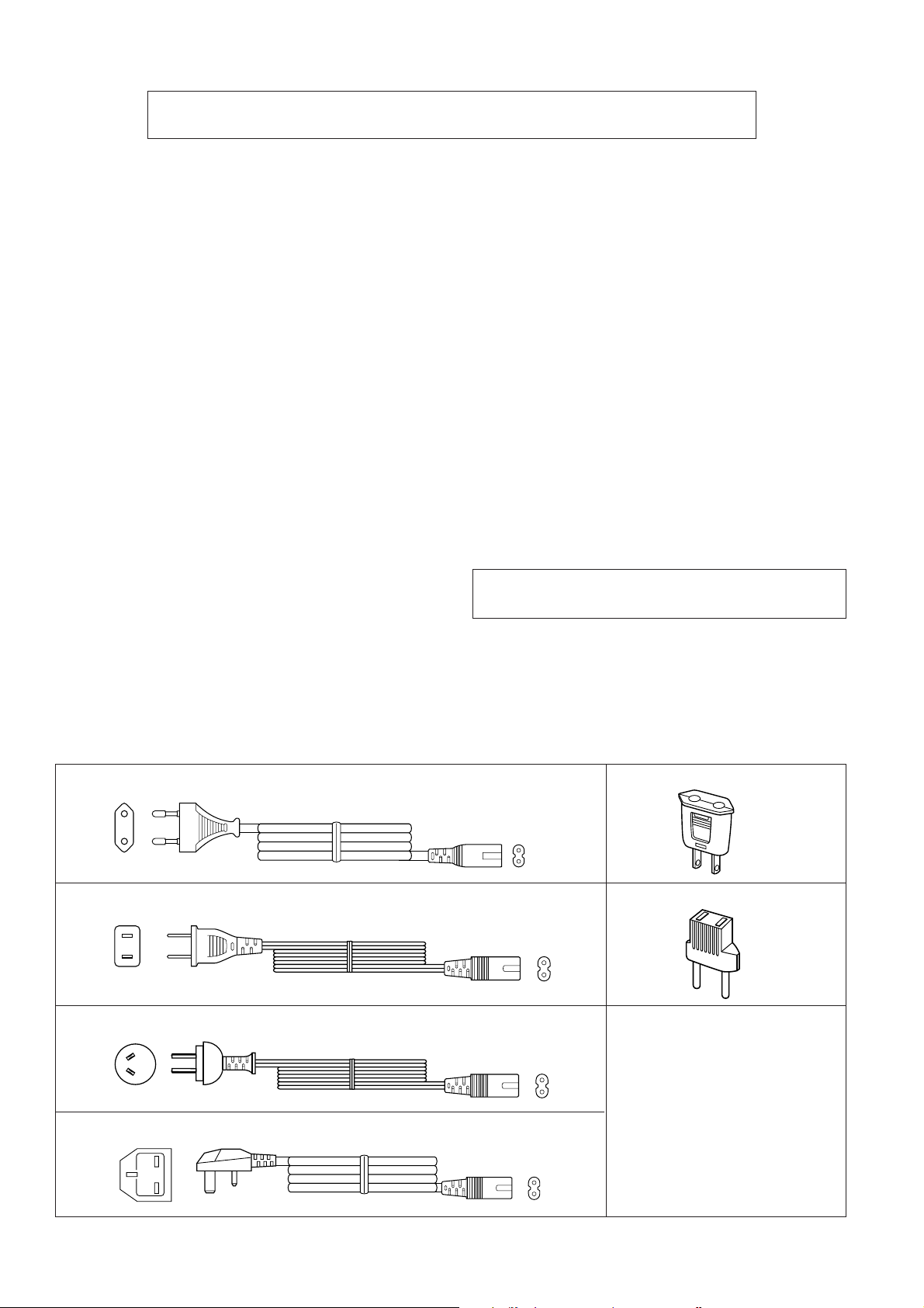
AC POWER SUPPLY CORD AND PLUG
9FGS9822020300
9FGS9821620000
9FGS9822020500
QPLGA0250AFZZ
QPLGA0253AFZZ
9FGS9822020400
– 2 –
Page 3
1. Extra Bass Control: X-BASS
2. Graphic Equalizer Controls
3. FM Stereo Indicator
4. Power Indicator
5. Function Selector Switch
6. Volume Control
7. Dubbing Speed/Built-in Microphone Switch
8. Built-in Microphone
9. Tuning Control
10. Fine Tuning Control
11. Band Selector Switch
12. Headphones Socket
13. Mixing Microphone Socket
14. FM Mode Switch
15. (TAPE 1) Cassette Compartment
16. (TAPE 1) Record Button: I
17. (TAPE 1) Play Button: 0
18. (TAPE 1) Rewind Button: 3
19. (TAPE 1) Fast Forward Button: 2
20. (TAPE 1) Stop/Eject Button: ■ 7
21. (TAPE 1) Pause Button: 6
22. (TAPE 2) Play Button: 0
23. (TAPE 2) Rewind Button: 3
24. (TAPE 2) Fast Forward Button: 2
25. (TAPE 2) Stop/Eject Button: ■ 7
26. (TAPE 2) Cassette Compartment
27. CD/Line Input Sockets
28. Beat Cancel Switch
29. FM/SW Telescopic Rod Aerial
30. Speaker Terminals
31. AC Voltage Selector
32. AC Power Input Socket
33. Battery Compartment
34. Tweeter
35. Woofer
36. Speaker Release Lever
37. Speaker Wire
0
3
0
3
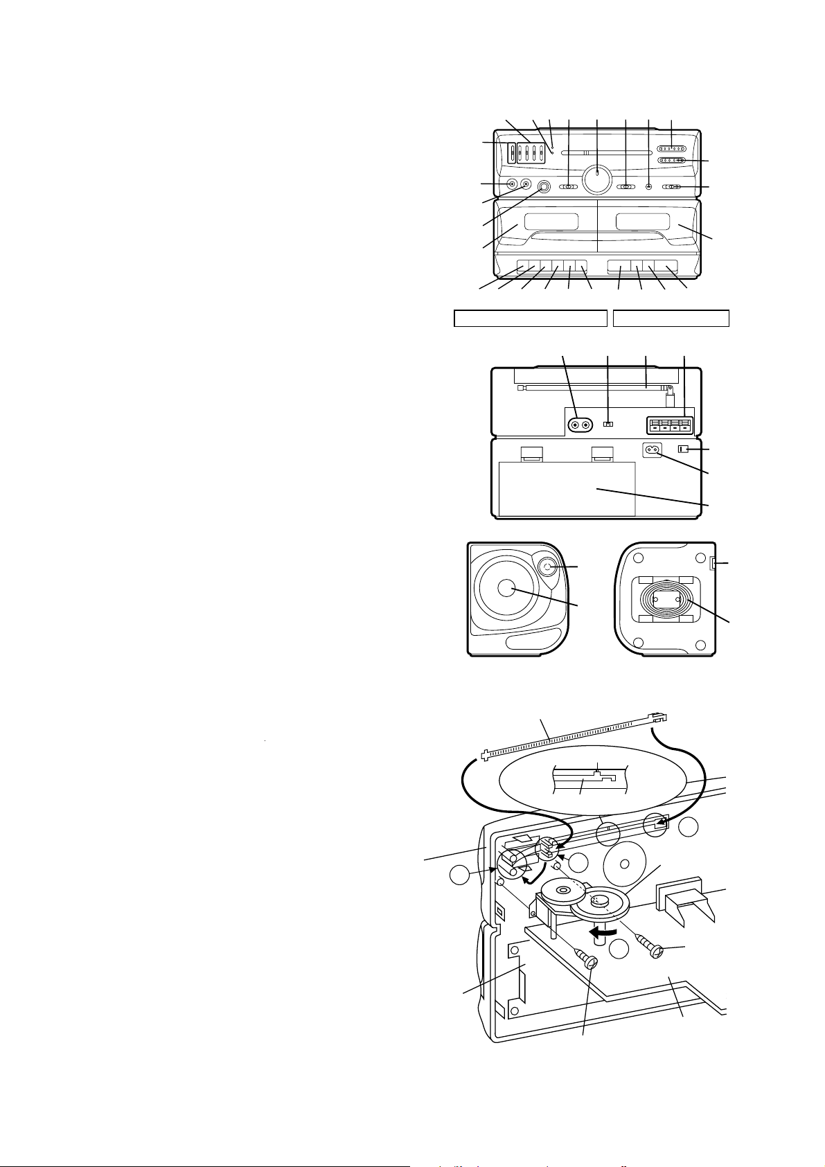
NAMES OF PARTS
2
1
12
13
14
15
16
17181920
3
4
56
21
789
23 24 25
22
TAPE 1 TAPE 2
27
28 29
30
34
35
WF-930Z
10
11
26
31
32
33
36
37
FITTING OF DIAL POINTER
1. Remove the main PWB. Attach the dial pointer as shown arrow
 on the front cabinet, putting it into the section indicated by arrow
È. Insert it between the arrows Ê.
2. Install the main PWB in the front cabinet and secure it with the two
screws.
3. Turn the dial drum in the direction indicated by arrow Ë. Set the
dial pointer to point "0", and then make the rest of the adjustments.
Front
Cabinet
Tape
Mechanism
C
Dial Pointer (203)
''0''Point
Dial Pointer (203)
B
Screw(601)
ø2 x4mm
Figure 3
A
Dial Drum (213)
D
Screw(606)
ø3 x8mm
Main PWB
– 3 –
Page 4
WF-930Z
DISASSEMBLY
Caution on Disassembly
Follow the below-mentioned notes when disassembling the
unit and reassembling it, to keep it safe and ensure excellent
performance:
1. Take cassette tape out of the unit.
2. Be sure to remove the power supply plug from the wall
outlet before starting to disassemble the unit and remove
the batteries from the unit.
3. Take off nylon bands or wire holders where they need be
removed when disassembling the unit. After servicing the
unit, be sure to rearrange the leads where they were
before disassembling.
4. Take sufficient care on static electricity of integrated
circuits and other circuits when servicing.
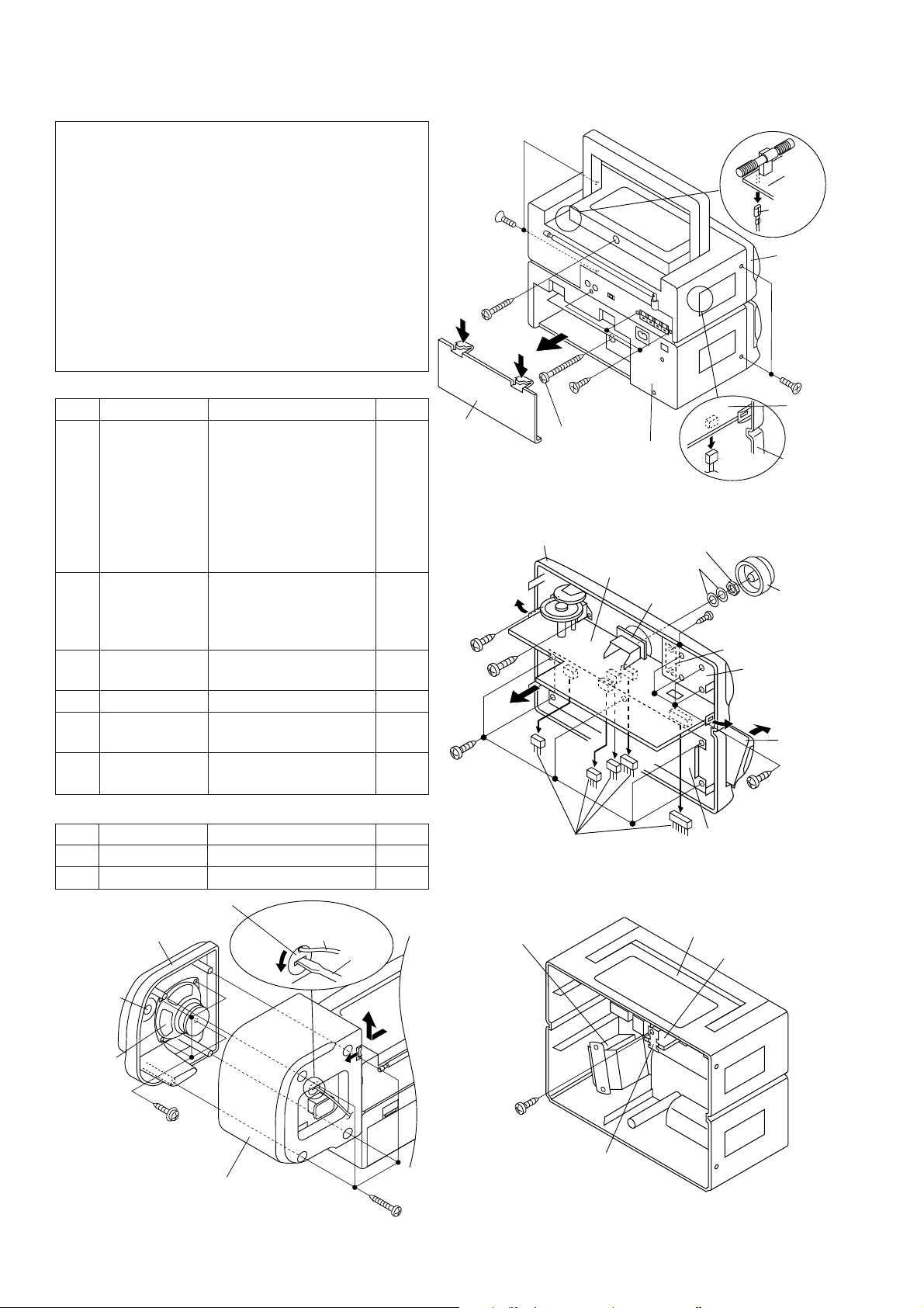
MAIN UNIT
STEP REMOVAL PROCEDURE FIGURE
1 Front Cabinet/ 1. Battery Compartment
Rear Cabinet Lid ...................(A1)x1 4-1
2. Screw ................(A2)x4
3. Screw ................(A3)x1
4. Screw ................(A4)x1
5. Screw ................(A5)x3
6. Socket ...............(A6)x1
7. Tip .....................(A7)x1
2 Main PWB/ 1. Knob .................(B1)x1 4-2
Volume PWB 2. Socket ...............(B2)x5
3. Screw ................(B3)x1
4. Screw ................(B4)x1
3 Graphic Equalizer 1. Screw ................(C1)x4 4-2
PWB
4 LED PWB 1. Screw ................(D1)x2 4-2
5 Tape Mechanism 1. Open the cassette holder 4-2
2. Screw ................(E1)x5
6 Power PWB 1. Screw ................(F1)x1 4-3
2. Bracket..............(F2)x1
SPEAKER
STEP REMOVAL PROCEDURE FIGURE
1 Front Panel 1. Screw ................(G1)x4 4-4
2 Woofer 1. Screw ................(G2)x4 4-4
(A2) x2
ø3 x10mm
(A3) x1
ø3 x14mm
(A1) x1
(B4) x1
ø2 x4mm
(B3) x1
ø3 x8mm
(E1) x5
ø3x 8mm
(A4) x1
ø3 x28mm
Front Cabinet
(B2) x5
(A5) x3
ø3 x8mm
Figure 4-1
Main
PWB
Figure 4-2
Rear
Cabinet
Washer
Volume
PWB
(A6) x1
Nat
(D1)x2
ø3x8mm
LED PWB
Tape
Mechanism
Main
PWB
(A7) x1
Front
Cabinet
(A2) x2
ø3 x10mm
Main
PWB
Front
Cabinet
(B1) x1
Graphic
Equalizer
PWB
Open
Cassette
Holder
(Left/Right)
(C1) x4
ø3x8mm
Tweeter
Woofer
Speaker Cord
Holder
Front Panel
(G2) x4
ø3x 8mm
Speaker Box
Figure 4-4
Speaker
Cord
Driver
(G1) x4
ø3 x14mm
UNIT
– 4 –
Power
Transeformer
(F1) x1
ø3 x8mm
Rear Cabinet
Power PWB
(F2) x1
Figure 4-3
Page 5
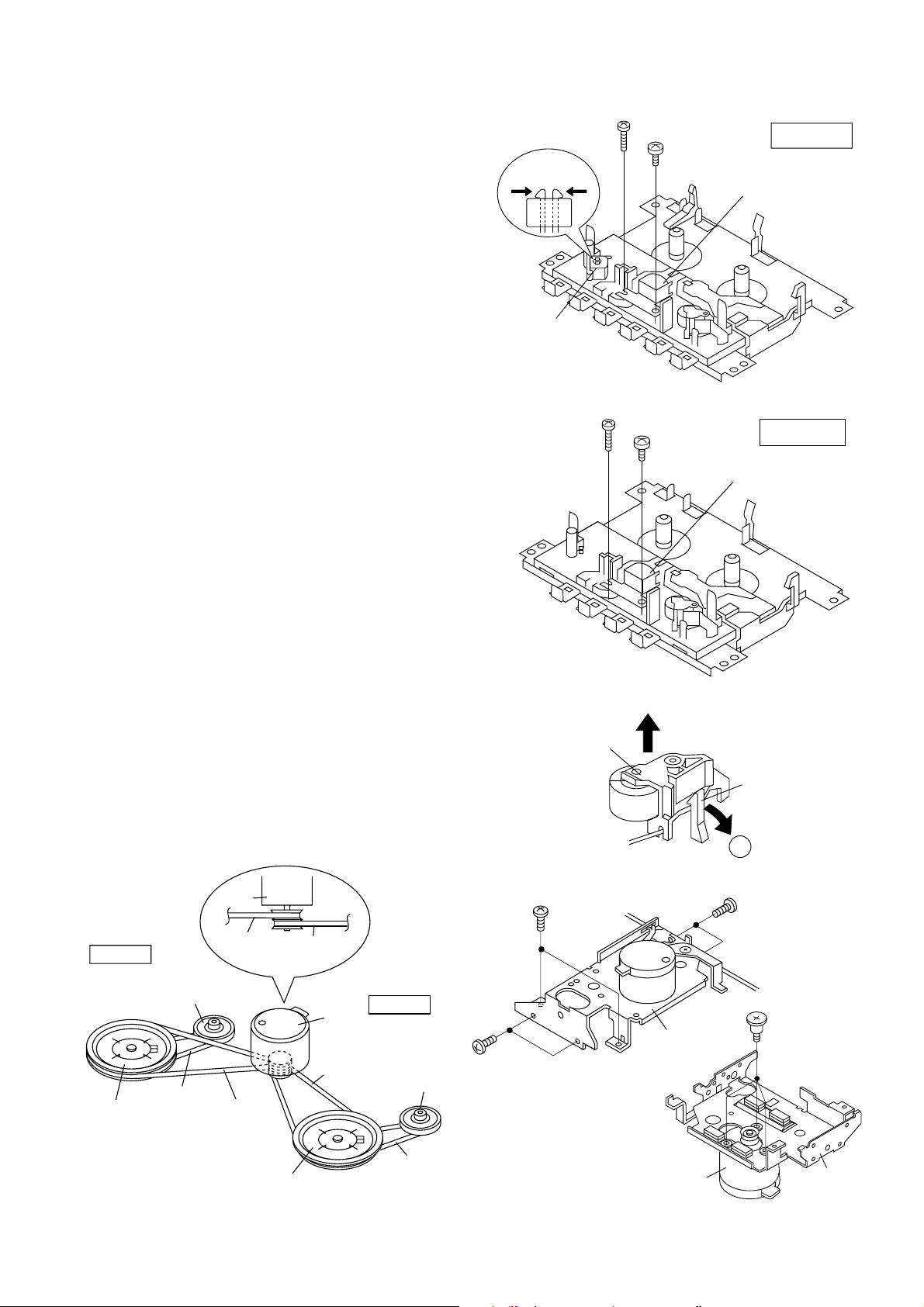
REMOVING AND REINSTALLING THE MAIN PARTS
TAPE MECHANISM SECTION
Perform steps 1, 2 and 5 of the disassembly method to remove
the tape mechanism. (See page 4.)
How to remove the record / playback, playback
and erase heads (See Fig. 5-1 and 5-2.)
1. Remove the screws (A1) x 2 pcs., to remove the record/
playback head.
2. Remove the hooks (A2) x 2 pcs., toward the center position
as shown in Fig. 5-1. and then extract the erase head upward.
3. Remove the screws (B1) x 2 pcs., to remove the playback
head.
Note:
After replacing the heads and performing the azimuth adjustment, be sure to apply screwlock.
How to remove the pinch roller (See Fig. 5-3.)
1. Carefully bend the pinch roller pawl in the direction of the
arrow Â, and remove the pinch roller (C1) upwards.
How to remove the motor (See Fig. 5-4.)
1. Remove the belt.
2. Remove the screws (D1) x 6 pcs., to remove the motor
bracket.
3. Remove the screws (D2) x 3 pcs., to remove the motor.
Note:
When mounting the motor, pay attention to the motor mounting
angle.
Hook
(A2) x2
Erase
Head
(B1) x1
ø2x7mm
(A1) x1
ø2x7mm
(A1) x1
ø2x3mm
Figure 5-1
(B1) x1
ø2x3mm
WF-930Z
TAPE 1
Record/Playback
Head
TAPE 2
Playback
Head
How to remove the belts (See Fig. 5-5.)
1. Remove the main belt (E1) x 1 pc., at the tape 1 side from the
motor pulley.
2. Remove the main belt (E2) x 1 pc., at the tape 2 side from the
motor pulley.
3. Remove the REW/FF belt (E3) x 2 pcs., from the REW/FF
roller.
4. Put on the belts in the reverse order of removal.
Note:
When putting on the belt, ascertain that the belt is not twisted,
and clean it.
Moter
TAPE 2
Frywheel
REW / FF
Clutch Ass'y
REW / FF
Belt
(E3) x1
TAPE 2
Main Bert
Main
Belt
(E2) x1
TAPE 1
Main Bert
Moter
Main
Belt
(E1) x1
TAPE 1
REW / FF
Clutch Ass'y
(D1) x2
ø2 x4mm
Pinch Roller
(C1)
(D1) x2
ø2 x4mm
Figure 5-2
Figure 5-3
Motor
Bracket
Pinch Roller
Pawl
A
(D1) x2
ø2 x4mm
(D2) x3
Special Screw
Frywheel
Figure 5-5
REW / FF
Belt
(E3) x1
– 5 –
Motor
Figure 5-4
Motor
Bracket
Page 6
WF-930Z
ADJUSTMENT
MECHANISM SECTION
• Driving Force Check
Torque Meter
Play: TW-2412 Tape 1: Over 50g
• Torque Check
Torque Meter
Play: TW-2111 30 to 60 g.cm 30 to 60 g.cm
Fast forward: TW-2231 55 to 120 g.cm 80 to 135 g.cm
Rewind: TW-2231 55 to 120 g.cm 80 to 135 g.cm
• Head Azimuth
Test Tape
MTT-114 Headphones Socket
• Tape Speed (Normal only)
Test Tape
MTT-111 Tape 1,2: VR501 3,000 ± 60 Hz Headphones
Adjusting
Point
Specified Value
Tape 2: Over 60 g
Specified Value
Tape 1 Tape 2
Instrument Connection
(Load resistance: 32 ohms)
Specified
Value
Instrument
Connection
socket(Load
resistance:
32 ohms)
TUNER SECTION
fL: Low-range frequency
fH: High-range frequency
• AM IF/RF
Specified
Test Stage
IF T3 Input: Antenna
MW Band fL: L6
Coverage fH: TC8
MW Tracking fL (600 kHz):
SW1 Band fL: L7
Coverage fH: TC4
SW1 Tracking fL (2.6 MHz):
SW2 Band fL: L8
Coverage fH: TC3
SW2 Tracking fL (8.5 MHz): L5
Value/Adjusting
Point
L3 (MW)
fH (1,400 kHz):
TC7
L4 (SW1)
fH (6.0 MHz):
TC2
fH (19 MHz): TC1
Instrument
Connection
Output: Pin 3 of IC2
TAPE SECTION
Position of each switch or control
Volume control Max
Beat cancel A
Function/Power Tape/Stand-by
Dubbing speed/Built-in Microphone OFF/Mic ON
• Bias Oscillation Frequency
Specified Value
Beat cancel A: 100 ± 4 kHz
• Playback Amplifier Sensitivity Check
Test Tape
MTT-118 1.3 V ± 3 dB Speaker terminal
Specified Value
B: 94 ± 4 kHz
C: 104 ± 4 kHz
Instrument Connection
(Load resistance: 3 ohms)
• FM IF/RF
Specified
Test Stage
IF T1
Detection T2
Band Coverage fL: L2
Tracking fL (88.0 MHz):
Value/Adjusting
Point
fH: TC6
L1
fH (108.0 MHz):
TC5
Instrument
Connection
Input: Antenna
Output: Pin 1 of IC1
• VCO Frequency
Specified ValueTest Stage
VR1 76 kHz ± 200 Hz Pin 13 of IC2
Instrument
Connection
– 6 –
Page 7

L3 L4
MW SW1
WF-930Z
MW
TRACKING
FM
TRACKINGfHfL
AM IF
IC2
13 24
VR1
VCO
T2
FM DETECTION
fL
fH
T3
112
SW2
TRACKING
fH fL
TC1
TC2
TC8
TC7
TC5
TC6
L1
IC1
19
T1
FM IF
fH fL
FM BAND
COVERAGE
fL
fH
SW2 BAND
COVERAGE
L5
TC3
TC4
L2
MW BAND
COVERAGE
SW1
TRACKING
fH fL
L6
fH fL
L8
L7
SW1 BAND
fL
COVERAGE
fH
MAIN PWB
MAIN PWB
Figure 7-1 ADJUSTMENT POINTS
TAPE SPEED
VR501
CNP501
IC401
– 7 –
Figure 7-2 ADJUSTMENT POINTS
Page 8

WF-930Z
0
(
R122
1
0
1
0
1
0
R
1
3
A
D
W
-
E
2
A
2
V
+
A
B
C
D
E
TAPE2
PLAYBACK HEAD
L-CH
R-CH
RECORD/PLAYBACK
L-CH
R-CH
F
ERASE
HEAD
TAPE1
G
MIXING
MICROPHONE
MIC101
BUILT-IN
MICROPHONE
HEAD
FM/SW
ROD ANTENNA
J102
L-CH
CD/LINE
R-CH
J101
CNS101
1
2
3
CNS103
1
2
3
BAND
SELCTOR
SW1G
FM
MW
SW1
SW2
D1
1N4148
L5
SW2
ANTENNA
L4
SW1
ANTENNA
L3
C10
5P
MW/SW1
BAR ANTENNA
CNP102
1
2
3
CNP104
1
2
3
44
(CH)
MAIN PWB-A1
VOLUME PWB-A2
FM BAND PASS
FILTER
BPF1
12
3
C1
10P
(CH)
SW1 : BAND SELECTOR
SW1C
SW2
SW1
MW
TC1
SW2
SW1
MW
TC2
C36
(CH)
FM
FM
MW
SW1
SW2
VC7
TC7
5P
C11
5P
(CH)
R150
47K
R151
47K
R152
2.2K
R139
C141
1/50
FM
SW101 : RECORD/PLAYBACK
RF AMP.
21
C2
0.001
SW1BSW1D
FT1
FINE TUNING
R140
1K
C142
0.018
(ML)
R141
100
4.7K
HI-SPEED DUBBING : ( )
MIC REC : < >
R138
1K
SW102
BEAT
CANCEL
C128
330P
C12
R137
8.2K
SW1FSW1H
R153
2.2K
C3
20P
(CH)
VC8
3P (CH)
C144
1/50
C125
150P
BCA
C127
FM
TC8
120P
VC5
TC5
C5
0.05
SW2
SW1
MW
FM
MW
SW1
SW2
C13
300P
C16
10P
(CH)
R142
330K
0.7V
0.1V
C145
220P
C143
0.001
C140
10/25
C121
130P
RPRP
SW101D
SW101B
RPRP
C129
0.001 (ML)
3
C4
5P
(CH)
FM
FM RF
L2
L1
C44
0.02
C15
0.0047
(styrol)
C37
5P
(CH)
MIC AMP.
Q101
9014 C
2.2V
C146
1/50
68
R143
R123
L101
22mH
C126
150P
L102
22mH
BIAS
OSC.
L105
MIX
4
VC6
OSC.
R1
100
TC3
47K
R144
LINE AMO.
1.2K
SW101C
SW101A
C130
0.02
TC6
C14
0.0015
(Styrol)
MIC
MUTING
Q102
9014 C
(0V)
(0V)
R146
10K
Q103
9014 C
5
C7
3P
(CH)
C6
27P (RH)
C41
0.02
TC4
(0.7V)
R136
4.7K
C122
15P
(CH)
130P
C8
D2
OSC
6
7
R2
33
FM IF
R4
T1
47
1N4148
+B
R7
47
SW2
OSC.
L8
R6
47
L7
SW1
OSC.
L6
MW
OSC.
C18
0.02
C38
C43
5P (CH)
0.02
SW101F
RECORD/
PLAYBACK
R145
4.7K
C148
47/10
SW103 :
R147
DUBBING SPEED
/MIC
10K
HIGH/
MIC OFF
NORMAL
C147
10/25
OFF/MIC ON
R134
<0V>
10K
<0.7V>
R101
56
820P
C101
C107
820P
C103
0.033
(ML)
C105
33/10
24 23 22
CH2/ACH2
CH1
C102
R124
1.2K
R125
C131
0.0082
NF
/B
CH1
NF
/B
/A
1234
C106
33/10
820P
C104
C108
820P
0.033
(ML)
R102
56
BIAS
OSC.
4.6V
27K
0.6V
47
(ML)
R126
C132
0.012
(ML)
IC1
TA7378P
FM FRONT END
VCCGND
98
C39
0.001
SW2
SW1
MW
FM
BAND
SELECTOR
+B
P
R
R148
220
SW103B
D101
1N4148
C149
10/25
<0V>
R161
68K
R103
180K
MATAL
OUT
MATAL
OUT
R104
180K
R162
68K
Q105
8050 D
0.4V
FM IF
10.7MHz
C9
0.02
R5
100
SW1A
SW1E
C27
1/50
100/10
R109
22K
5.6K
R105
R107
4.7K
21 20
R106
5.6K
R108
4.7K
R110
22K
R127
100
C134
CF1
C28
R149
4.7K
PRE
OUT
PRE
OUT
100/10
220K
123
C40
0.001
24
AM
OSC
FM IF
IN
FM
1234
MW
SW1
C30
SW2
0.04
C29
0.02
R8
100
+B
D105
1N4148
1N4148
R159
22K
D103
1N4148
C109
4.7/50
10K
R135
19 18 17 16 15 14 13
A/B
VCC REC
IC101
TA8189N
MIX
GND1
OUT
6
5
7
R129
10K
C110
4.7/50
D102
1N4148
R132
220
R
SW101E
P
R128
100
SW101 : RECORD/PLAYBACK
HI-SPEED DUBBING : ( )
NORMAL SPEED : OTHER
R3
C17
10/25
D5
C138
C135
22/16
R130
10K
+B
C19
0.02
23
RF
AM
MIX
T3
AM IF
D4
1N4148
C42
4.7/50
D6
1N4148
D104
1N4148
2200/10
C137
2.2/50
PRE AMP.
M/N
89
R131
10K
L1 TC5
FM
TRACKING
L2 TC6
FM BAND
COVERAGE
22
VCCAM
C31
R113
2.2K
C111
4.7/50
R111
180K
OUT
REC
OUT
R112
180K
R114
C112
4.7/50
2.2K
FM DET
21
22/16
L3 TC7
fHfL
MW
TRACKING
L6 TC8
fHfL
MW BAND
COVERAGE
+B
C20
T2
0.0039
(ML)
R9
3.9K
1920 17 16 1518
AM
IC2
DET
LA1805
AMP. & FM MPX.
AM
GND GND GND
IF
6
5
123
CF2
460kHz
R510
D503
22K
1N4148
R154
C150
22/16
C153
0.001
R155
330K
C117
0.015
R115
(ML)
220
C113
10/25
C151
330P
ALC
REC
REC
NF
IN
REC
REC
GND
IN
NF
10 11 12
C152
330P
C114
10/25
R116
C118
220
0.015
(ML)
C154
0.001
+B
REGULATOR
D501
1N4148
0.02
C502
0.02
C507
R503
10K
+B
Q502, Q503 : SWITCHING
fHfL
fHfL
C21
0.04
C22
470P
C23
(ML)
0.0082
+B
AM IF
100
C119
4.7/50
VOLTAGE
Q501
8050 D
7.6V
C503
220/10
Q502
9014 C
(0.7V)
0V
10K
R504
R11
22K
7
+B
L103
2.7mH
R133
C120
4.7/50
L104
2.7mH
12V
8.2V
R502
100
MTZJ8.2C
L4 TC2
SW1
TRACKING
L7 TC4
SW1 BAND
COVERAGE
R10
470K
C24
3.3/50
FM
DET
OUT
89
C33
1M
C136
22/16
SW401B
R501
680
C504
0.02
D502
(0V)
0.7V
0V
(0V)
fHfL
fHfL
FM M
MONO
MPX
IN
L-CH R-CH
C32
0.012 (ML)
0.012 (ML)
STAND
POW
R119
47K
+B
C155
0.01
22K
R157
R158
22K
C156
0.01
R120
47K
(10.2V)
(0V)
0.7V
Q503
9014 C
C505
0.02
SW
TR
SW
CO
SW
R
10
C25
10
R
1
R
1
+B
22K
R121
ST
RA
PO
0V
H
• NOTES ON SCHEMATIC DIAGRAM can be found on page 12.
1
2
34 5
Figure 8 SCHEMATIC DIAGRAM (1/2)
– 8 –
6
Page 9

WF-930Z
5
0.012
(ML)
5
TC1
C2
fH
H
SW2
TRACKING
NG
TC3
C4
fH
H
SW2 BAND
ND
COVERAGE
GE
SW301
FM MODE
STEREO
MONO
R12
100K
C25
3.3/50
16 15 14 13
PX
IN
-CH R-CH
11 1210
9
C35
R15
4.7/50
10K
R16
C34
10K
4.7/50
C32
0.012 (ML)
STAND-BY/TAPE
RADIO
POWER ON/CD
+B
+B
R119
47K
+B
C155
0.01
22K
22K
R121
R157
R158
22K
22K
R122
C156
0.01
R120
47K
STAND-BY/TAPE
401B
RADIO
POWER ON/CD
01
0
04
02
R505
10K
(10.2V)
0V
R506
(0V)
100K
0.7V
0V
Q503
(0V)
9014 C
C505
0.02
ING
L5
fL
SW2
TRACKING
L8
fL
SW2 BAND
COVERAGE
C26
VCO
0.0015
VR1
(Styrol)
10K (B)
R13
1.5K
VCO
R14
1K
R18
R17
2.7K
2.7K
SW401A
FUNCTION
STAND-BY
/TAPE
POWER ON
/CD
STAND-BY
/TAPE
10.3V
(10.3V)
VR501
2.2K (B)
TAPE
SPEED
Q504 : MOTOR CONTROL
RADIO
RADIO
POWER ON/CD
L501
22µH
10.9V
(10.8V)
Q504
8555 D
10.9V
(6.9V)
R509
SW401D
SW401 :
FUNCTION
SELECTOR
56K
R508
470
+B
+B
R117
22K
SW401C
R118
22K
C506
100/25
+B
+B
R507
6.8K
LED PWB-A3
CNP505
CNS506
1
D522
1
1
2
2
3
3
4
4
L-34HD
POWER/BATT.
D521
L-34HD
4
FM STEREO
GRAPHIC EQUALIZER PWB-B
C258
0.022
R252
(ML)
1K
R253
C253
2.2K
1
1
C251
4.7/50
C275
16
CNS251
CNP201
100/10
R254
2.2K
R251
1K
4.7/50
23 21
C252
4.7/50
C254
4.7/50
C257
0.022
(ML)
GRAPHIC EQUALIZER
R522
+B
470
+B
330
R257
234
6
5
234
6
5
VOLUME
C401
+B
0.001
(ML)
C403
0.15
(ML)
R401
2.7K
R402
2.7K
C404
0.15
(ML)
C402
0.001
(ML)
50K (B)
VR401A
R406
VR401B
50K(B)
VOLUME
R405
1K
1K
<0.7V>
<0.7V>
R403
1K
POWER PWB-A4
CNS504
CNP503
1
1
1
2
2
CNS502
CNP501
1
2
3
4
5
6
7
8
1
2
3
4
5
6
7
8
C601
2
0.02
D601
1N5392
D602
1N5392
C602
0.02
SW503
TAPE2 PLAY
SW502
TAPE1 MAIN
+
–
B
M
A
SW501
TAPE2 MAIN
IC1
PIN
VOLTAGE
NO.
1
0.7V
2
1.4V
3
4.9V
4
1.4V
5
0V
6
5V
7
1.4V
8
4.9V
9
4.8V
10kHz 1kHz
VR251B
50K (B)
C255
4.7/50
C272
C256
4.7/50
VR251A
50K (B)
10kHz
MIC REC : < >
Q401, Q402 : MUTING
C405
4.7/50
R407
33K
0V
Q401
9014 C
0V
0V
Q402
9014 C
0V
R408
33K
R404
C406
1K
4.7/50
C603
0.02
D603
1N5392
D604
1N5392
C604
F601
0.02
T1.25A
L 250V
M501
TAPE
MOTOR
PIN
VOLTAGEFMVOLTAGE
NO.
1
1.6V
2
1.6V
3
5.1V
4
1.4V
5
1.6V
6
0V
7
5.6V
8
0V
9
2.3V
10
2.3V
11
4.6V
12
0.9V
GRAPHIC EQUALIZER
3.3kHz
VR252A
50K (B)
C261
C265
C259
0.001
(ML)
151917 11
(ML)
0.033
C274
1/50
0.033
(ML)
0.1
(ML)
(ML)
C263
0.0033
13
141618202224
1012
C268
0.01
(ML)
C270
0.33/50
VR255B
50K (B)
X-BASS
POWER AMP.
5
C409
100/10
120
R409
4
C417
47/25
C407
0.001
C408
0.001
BATTERIES
DC12V [ “D” size (UM/SUM-1,
R20 or HP2) battery x 8
TRANSFORMER
120
R410
100/10
POWER
C410
T601
C420
22/25
7
9
8
AC220V – 240V
AC110V – 127V
0V
HI-SPEED DUBBING : ( )
IC2
PIN
VOLTAGEFMVOLTAGE
NO.
AM
13
1.7V
1.7V
6.2V
0.7V
1.7V
0V
5.7V
0V
2.3V
2.3V
6.2V
0.9V
VR253A
50K (B)
1.1V
14
1.7V
15
1.7V
16
1.7V
17
1.5V
18
1.6V
19
0.4V
20
5.5V
21
5.3V
22
0.6V
23
1.6V
24
1.5V
330Hz
VR254A
50K (B)
C269
0.33/50
C267
0.01
(ML)
9
C273
1/50
(ML)
C271
0.033
3
57
68
(ML)
C264
0.0033
VR254B
50K (B)
330Hz
IC401
BA5415
NF
FILTER
NF
STAND
-BY
6
50/60Hz
(ML)
C260
0.001
C266
C262
0.1
0.033
(ML)
(ML)
VR253B
50K (B)
GRAPHIC EQUALIZER
C411
100/16
3
OUTPUT
2
12
GND
11
OUTPUT
10
C412
VCC
100/16
1
C419
2200/25
SW601
VOLTAGE
SELECTOR
C413
0.22
(ML)
C416
1000/16
C414
0.22
(ML)
50/60Hz
FM SIGNAL
MW/SW1/SW2 SIGNAL
PLAYBACK SIGNAL
RECORD SIGNAL
AM
0V
1.7V
1.7V
1.7V
1.7V
1.6V
0.9V
6.2V
6.2V
1.1V
1.6V
1.6V
X-BASS
VR255A
50K (B)
1
24
VR252B
50K (B)
3.3kHz1kHz
C415
1000/16
1K
R413
1K
R414
SO601
AC POWER INPUT
SOCKET
MIC REC : < >
IC401
PIN
VOLTAGE
NO.
1
12V
2
5.9V
3
9.9V
4
0.6V
5
0V
6
12V
7
10.8V
8
0V
9
0.6V
10
9.9V
11
5.9V
12
0V
IC251
GRAPHIC
BA3822LS
EQUALIZER
R415
100
R416
100
+
R-CH
–
–
L-CH
+
J401
SPEAKERS
TERMINAL
IC101
PIN
VOLTAGE
NO.
1
0V
2
0V
3
1.2V
4
1.3V
5
1.4V
6
1.3V
7
0V
8
0V
9
2V
10
1.3V
11
0V
12
0V
13
0.9V
14
0V
15
1.3V
16
2V
17
1.4V
18
5.5V
19
1.6V <0V>
20
1.4V
21
1.3V
22
1.2V
23
0V
24
0V
J403
HEADPHONES
(3.5V)
IC251
PIN
VOLTAGE
NO.
1
4.3V
2
4.3V
3
4.9V
4
4.9V
5
4.3V
6
4.3V
7
4.9V
8
4.9V
9
4.3V
10
4.3V
11
4.9V
12
4.9V
13
4.3V
14
4.3V
15
4.9V
16
4.9V
17
3.2V
18
2V
19
2V
20
3.2V
21
2.6V
22
2.6V
23
5.23V
24
0V
SP703
TWEETER
R-CH
SP701
WOOFER
SP702
WOOFER
L-CH
SP704
TWEETER
SPEAKERS
SPEAKERS
78 9101112
Figure 9 SCHEMATIC DIAGRAM (2/2)
– 9 –
Page 10

WF-930Z
A
B
C
D
E
F
G
WH
WH
SW502
TAPE1
MAIN
SW503
TAPE2
PLAY
TAPE1
ERASE(67)
HERAD
TAPE2
RECORD/PLAYBACK(65)
HEAD
RD
WH
VOLTAGE SELECTOR
AC220V-240V AC110V-127V
COLOR TABLE
BROWN
BR
RED
RD
ORANGE
OR
YELLOW
YL
GREEN
GR
BLUE
BL
VIOLET
VL
GRAY
GY
WHITE
WH
BLACK
BK
PINK
PK
AB
+-
M501
TAPE
MOTOR
RECORD/PLAYBACK(66)
HEAD
RD
WH
SW601
RD BL
FM/SW ROD ANTENNA (229)
DC12V["D"size(UM/SUM-1,
R20 or HP2)BATTERY X 8]
(85)
BK
SW501
TAPE2
MAIN
BR
BR
BATTERIES
BR
1
RD
2
OR
3
YL
4
GR
5
BL
6
VR
7
GY
8
RD
4
3
WH
2
BK
1
RD
3
2
WH
1
BR
BK
T601
POWER
TRANSFORMER
CNS502
CNS103
CNS101
SO601
AC POWER INPUT
SOCKET
AC110V-127V
50/60Hz
AC220V-240V
50/60Hz
GRAPHIC EQUALIZER PWB-B
C273
C271
C258
B
B
B
B
B
10
20
24
R252
IC251
2
VR255
VR254
VR253
VR252
C402
C401
C404
1
5
15
23
C275
C259
R401
C403
R402
VOLUME
C267
C261
R257
C269
VR251
C263
VR401
A
A
C265
A
A
C255
A
C251
A
B
C260
C264
C274
C270
C266
C262
C268
C272
VOLUME PWB-A2
GR
GR
OR
WH
WH
C604
C602
F601 T1.25A L 250V
RD
(245) (247)
C254
C253
R253
C257
C256
R251
C252
POWER PWB-A4
D604
C603
D602
C601
D603
D601
D605
BK
MIN
MAX
VR255 X-BASS
VR254
330Hz
VR253
1kHz
VR252
GRAPHIC
CNS251
1
2
3
4
5
6
CNS504
2
1
EQUALIZER
3.3Hz
VR251
10kHz
R254
BR
RD
OR
YL
GR
BL
61
RD
WH
BK
BK
WH
RD
BK
RD
(232)
(248)
WH
(246)
H
1
2
34 5
6
Figure 10 WIRING SIDE OF P.W.BOARD (1/2)
– 10 –
Page 11

MAIN PWB-A1
WF-930Z
MIC101
BUILT-IN
MICROPHONE
BK
WH
FM MODE PWB-C
SW401
SELECTOR
FUNCTION
POWER ON STAND-BY
OR
FT1
FINE TUNING
J403
J101
MIXING
GY
RD
YL
WH
CD/LINE RADIO TAPE
SW103
DUBBING
SPEED/
MIC
MIC OFF MIC ON
HIGH NORMAL OFF
SW1 BAND SELECTOR
HEADPHONES
MICROPHONE
WH
C141
BK
SW301
FM MODE
MONO
STEREO
3
BD
1
AC
SW401
RD
WH
FM
SW2 MWSW1
WH
RDRD
R415
R416
R140
R141
C142
SW103
123
HD
GC
FB
EA
SW1
R139
R143
Q101
C145
C146
R138
SW301
BPF1
RD
C143
R142
R144
C13
C144
E
B
C
R148
R527
C140
CNP201
C43
C10
L5
C15
R6
R7
R505
Q503 CBE
C505
Q502
CBE
TAPE SPEED
VR501
C148
R145
CB
E
Q102
R121
R146
R147
R122
R137
R136
6
5
4
3
2
1
C11
TC2
TC1
C37
L8 L7 L6
WH
RD
BK
C147
R18
C12
TC3
R504
C
B
E
Q504
BK
CNP104
R17
OR
VC7 VC5
TC7 TC5
TC8 TC6
VC8 VC6
C14
R506
TC4
R508
WH
L102
C35
R8
R15
R16
L501
R509
L101
CF2
T3
C6
C38
C506
R507
R503
R118
C122
C125
4
3
2
1
C27
321
WH
CNP501
1
2
3
4
5
6
7
8
C507
C502
R131
A
C126
B
C
D
E
C121
F
SW101
R159
C34
L1
C3
C8
R2
C16
YL
RD
13
12
CNP503
C504
D502
C503
C501
EBC
D501
SW101
RECORD/
PLAYBACK
RECORD PLAYBACK
C108
R124
C112
C106
C104
3
2
CNP102
1
C103
C105
C111
R161
R123
R128
R526
R510
R132
C33
C32
C31
1 5 10 12
C30
123
CF1
C19
C1
C2
C5
C4
C44
IC1
C7
987654321
C39
L2
C18
R5
C40
MW
C419
121110987654321
R501
R502
C410
Q501
R408
C406
D5
C42
D101
C135
C156
R162
R158
R156
R102
R108
R129
R106
R104
R130
C102
1 5 10 12
IC101
24 20 15 13
C101
R101
C107
R103
R107
R105
D503
R12
C26
C28
C25
C24
IC2
R9
24 20 15 13
C29
R4
R1
D1
GR
C17
C9
D2
R3
L3 MW/SW1 BAR ANTENNA
C414
C412
D6
C152
R135
C150
R13
R11
C23
T2
T1
C408
R149
C151
C
B
E
D105
R14
C21
C41
Q103
R155
R157
VCO
C110
C155
R134
VR1
C22
C20
R10
R410
C149
R112
C120
C420
C417
C113
C109
R111
C409
R407
RD
R409
4
3
2
1
C114
C137
C119
C153
R117
E
B
C
R404
Q402
C154
CNP505
C413
IC401
C411
C405
C407
EBC
R406
BK
R120
R110
L104
C118
D102
R116
R114
C136
R133
C138
D103
R127
R150
R152
R153
R109
R119
R151
4321
BK
GR
SW1
R405
D104
R113
R115
R154
R522
L4L3
Q401
R403
WH
C117
L103
CNS506
C416
R414
R413
C415
WH
C128
BK
C129
C127
L105
C134
D4
YL
OR
RD
BR
LED PWB-A3
R125
1
4
C130
C131
C132
BCE
D522
D521
TERMINALS
R126
Q105
J401
SPEAKER
L-CH
R-CH
C
SW102
B
BEAT
CANCEL
A
L-CH
J102
CD/LINE
R-CH
78 9101112
Figure 11 WIRING SIDE OF P.W.BOARD (2/2)
– 11 –
Page 12

WF-930Z
NOTES ON SCHEMATIC DIAGRAM
• Resistor:
To differentiate the units of resistors, The symbol as K and
M are used: the symbol K means 1000 ohm and the symbol
M means 1000 kohm and the resistor without any symbol is
an ohm resistor. The resistor designated “Fusible” is a fuse
type resistor.
• Capacitor:
To indicate the unit of capacitor, a symbol P is used: this
symbol P means pico-farad and the unit of the capacitor
without such a symbol is microfarad. As to electrolytic
capacitor, the expression “capacitance/withstand voltage” is
used.
(CH),(RH),(UJ): Temperature compensation
(ML): Mylar type
(S): Styrol type
• The indicated voltage in each section is the one measured by
Digital Multimeter between such a section and the chassis
with no signal given.
• Schematic diagram and Wiring Side of P.W. Board for this
model are subject to change for improvement without prior
notice.
• Parts marked with “ î ” ( ) are important for maintaining
the safety of the set. Be sure to replace these parts with
specified ones for maintaining the safety and performance of
the set.
REF. NO.
SW1 BAND SELECTOR SW2
SW101 RECORD/PLAYBACK PLAYBACK
SW102 BEAT CANCEL A
SW103 DUBBING SPEED/MIC OFF/MIC ON
SW301 FM MODE MONO
SW401 FANCTION SELECTOR TAPE/STAND-BY
SW501 TAPE 2 MAIN OFF
SW502 TAPE 1 MAIN OFF
SW503 TAPE 2 PLAY OFF
SW601 VOLTAGE SELECTOR AC 220-240V
POSITIONDESCRIPTION
FRONT
VIEW
EBC
8050 D
8550 D
9014 C
Figure 12-1 TYPE OF TRANSISTOR AND LED
FRONT
VIEW
L-34HD
– 12 –
Page 13

PARTS GUIDE
“HOW TO ORDER REPLACEMENT PARTS”
To have your order filled promptly and correctly, please furnish the
following information.
1. MODEL NUMBER 2. REF. No.
3. PART NO. 4. DESCRIPTION
MARK: SPARE PARTS-DELIVERY SECTION
WF-930Z
MODEL WF-930Z(BK)
For U.S.A. only
Contact your nearest SHARP Parts Distributor to order.
For location of SHARP Parts Distributor,
Please call Toll-Free;
1-800-BE-SHARP
Explanation of capacitors/resistors parts codes
Capacitors
VCC ........................Ceramic type
VCK ........................Ceramic type
VCT.........................Semiconductor type
VC • • MF ................Cylindrical type (without lead wire)
VC • • MN................Cylindrical type (without lead wire)
VC • • TV.................Square type (without lead wire)
VC • • TQ ................Square type (without lead wire)
VC • • CY ................Square type (without lead wire)
VC • • CZ ................Square type (without lead wire)
VC • • • • • • • • • J....The 13th character represents capacity difference.
("J" ±5%, "K" ±10%, "M" ±20%, "N" ±30%,
"C" ±0.25 pF, "D" ±0.5 pF, "Z" +80-20%.)
If there are no indications for the electrolytic capacitors, error is ±20%.
Resistors
VRD ........................Carbon-film type
VRS ........................Carbon-film type
VRN ........................Metal-film type
VR • • MF ................Cylindrical type (without lead wire)
VR • • MN................Cylindrical type (without lead wire)
VR • • TV.................Square type (without lead wire)
VR • • TQ ................Square type (without lead wire)
VR • • CY ................Square type (without lead wire)
VR • • CZ ................ Square type (without lead wire)
VR • • • • • • • • • J....The 13th character represents error.
("J" ±5%, "F" ±1%, "D" ±0.5%.)
If there are no indications for other parts, the resistors are ±5%
carbon-film type.
NOTE:
Parts marked with “ ” are important for maintaining the safety of the set.
Be sure to replace parts with specified ones for maintaining the safety and performance of the set.
— 1 —
Page 14

WF-930Z
PART CODE
★
PRICE
RANK
DESCRIPTIONNO.
INTEGRATED CIRCUITS
IC1 9FGS3200737872 J AE FM Front End,TA7378P
IC2 9FGS3200180561 J AK IF Amp.& FM MPX.,LA1805
IC101 9FGS3200818972 J AH Pre Amp.,TA8189N
IC251 9FGS3200382257 J AH Graphic Equalizer,BA3822LS
IC401 9FGS3200541557 J AL Power Amp.,BA5415
TRANSISTORS
Q101ç103 9FGS3390140332 J AB Silicon,NPN,9014 C
Q105 9FGS3380500432 J AC Silicon,NPN,8050 D
Q401,402 9FGS3390140332 J AB Silicon,NPN,9014 C
Q501 9FGS3380500432 J AC Silicon,NPN,8050 D
Q502,503 9FGS3390140332 J AB Silicon,NPN,9014 C
Q504 9FGS3385500432 J AC Silicon,PNP,8550 D
DIODES
D1,2 9FGS3600414857 J AA Silicon,1N4148
D4ç6 9FGS3600414857 J AA Silicon,1N4148
D101ç105 9FGS3600414857 J AA Silicon,1N4148
D501 9FGS3600414857 J AA Silicon,1N4148
D502 9FGS3710823557 J AB Zener,8.2V,MTZJ8.2C
D503 9FGS3600414857 J AA Silicon,1N4148
D521,522 9FGS3523200100 J AB LED,Red,L-34HD
îD601ç604 9FGS3600539200 J AB Silicon,1N5392
!
FILTERS
BPF1 9FGS6319803001 J AE FM Band Pass Filter
CF1 9FGS6321072001 J AC FM IF,10.7 MHz
CF2 9FGS6324550001 J AD AM IF,460 kHz
TRANSFORMERS
L105 9FGS4761000601 J AD Bias Oscillation
T1 9FGS4741000701 J AC FM IF
T2 9FGS4741000701 J AC FM Detection
T3 9FGS4731000511 J AC AM IF
!
îT601 9FGS4857001232 J AR Power
COILS
L1 9FGS4710040804 J AA FM RF
L2 9FGS4710345803 J AC FM Oscillation
L3 9FGS4608011717 J AB MW/SW1 Bar Antenna
L4 9FGS4691806710 J AB SW1 Antenna
L5 9FGS4720300410 J AC SW2 Antenna
L6 9FGS4721000510 J AC MW Oscillation
L7 9FGS4721000520 J AC SW1 Oscillation
L8 9FGS4721000530 J AC SW2 Oscillation
L101,102 9FGS4522340502 J AC 22 mH,Choke
L103,104 9FGS4527240502 J AC 2.7 mH,Choke
L501 9FGS4522042002 J AC 22 µH,Choke
VARIABLE RESISTORS
VR1 9FGS5392103001 J AC 10 kohm (B),Semi-VR [VCO]
VR251ç254 9FGS5342503002 J AD 50 kohms (B)×2
VR255 9FGS5342503001 J AD 50 kohms (B)×2 [X-BASS]
VR401 9FGS5323503001 J AF 50 kohms (B)×2 [Volume]
VR501 9FGS5392222001 J AC 2.2 kohms (B),Semi-VR
[Graphic Equalizer]
[Tape Speed]
VARIABLE CAPACITORS
FT1 9FGS5451112001 J AH Fine Tuning
TC1,2 9FGS5471112001 J AD Trimmer,10 pF
TC3,4 9FGS5471112002 J AD Trimmer,10 pF
VC5ç8 9FGS5444111001 J AL Variable Capacitor with Trimmer
(TC5ç8)
CAPACITORS
C1 VCCCPU1HH100J J AA 10 pF (CH),50V
C2 VCKYPU1HB102K J AA 0.001 µF,50V
C3 VCCCPU1HH200J J AA 20 pF (CH),50V
C4 VCCCPU1HH5R0C J AA 5 pF (CH),50V
C5 VCKZPU1HF203Z J AA 0.02 µF,50V
C6 VCCRPU1HH270J J AA 27 pF (RH),50V
PRICE
NO. PARTS CODE
C7 VCCCPU1HH3R0C J AA 3 pF (CH),50V
C8 VCCCPU1HH150J J AA 15 pF (CH),50V
C9 VCKZPU1HF203Z J AA 0.02 µF,50V
C10,11 VCCCPU1HH5R0C J AA 5 pF (CH),50V
C12 VCCCPU1HH3R0C J AA 3 pF (CH),50V
C13 9FGS4323014120 J 300 pF,50V,Styrol
C14 VCQSMA1HL152J J AB 0.0015 µF,50V,Styrol
C15 VCQSMA1HL472J J AB 0.0047 µF,50V,Styrol
C16 VCCCPU1HH100J J AA 10 pF (CH),50V
C17 RC-GZA106AF1E J AA 10 µF,25V,Electrolytic
C18,19 VCKZPU1HF203Z J AA 0.02 µF,50V
C20 VCQYKU1HM392K J AA 0.0039 µF,50V,Mylar
C21 VCKZPU1HF403Z J AA 0.04 µF,50V
C22 VCKYPU1HB471K J AA 470 pF,50V
C23 VCQYKU1HM822K J AA 0.0082 µF,50V,Mylar
C24,25 RC-GZA335AF1H J AB 3.3 µF,50V,Electrolytic
C26 VCQSMA1HL152J J AB 0.0015 µF,50V,Styrol
C27 RC-GZA105AF1H J AB 1 µF,50V,Electrolytic
C28 RC-GZA107AF1A J AB 100 µF,10V,Electrolytic
C29 VCKZPU1HF203Z J AA 0.02 µF,50V
C30 VCKZPU1HF403Z J AA 0.04 µF,50V
C31 RC-GZA226AF1C J AB 22 µF,16V,Electrolytic
C32,33 VCQYKU1HM123K J AA 0.012 µF,50V,Mylar
C34,35 RC-GZA475AF1H J AB 4.7 µF,50V,Electrolytic
C36ç38 VCCCPU1HH5R0C J AA 5 pF (CH),50V
C39,40 VCKYPU1HB102K J AA 0.001 µF,50V
C41 VCKZPU1HF203Z J AA 0.02 µF,50V
C42 RC-GZA475AF1H J AB 4.7 µF,50V,Electrolytic
C43,44 VCKZPU1HF203Z J AA 0.02 µF,50V
C101ç104 VCKYPU1HB821K J AA 820 pF,50V
C105,106 RC-GZA336AF1A J AB 33 µF,10V,Electrolytic
C107,108 VCQYKU1HM333K J AB 0.033 µF,50V,Mylar
C109ç112 RC-GZA475AF1H J AB 4.7 µF,50V,Electrolytic
C113,114 RC-GZA106AF1E J AA 10 µF,25V,Electrolytic
C117,118 VCQYKU1HM153K J AA 0.015 µF,50V,Mylar
C119,120 RC-GZA475AF1H J AB 4.7 µF,50V,Electrolytic
C121,122 VCCSPU1HL131J J AB 130 pF,50V
C125,126 VCCSPU1HL151J J AA 150 pF,50V
C127 VCCSPU1HL121J J AA 120 pF,50V
C128 VCCSPU1HL331J J AA 330 pF,50V
C129 VCQYKU1HM102K J AA 0.001 µF,50V,Mylar
C130 VCKZPU1HF203Z J AA 0.02 µF,50V
C131 VCQYKU1HM822K J AA 0.0082 µF,50V,Mylar
C132 VCQYKU1HM123K J AA 0.012 µF,50V,Mylar
C134 RC-GZA107AF1A J AB 100 µF,10V,Electrolytic
C135,136 RC-GZA226AF1C J AB 22 µF,16V,Electrolytic
C137 RC-GZA225AF1H J AB 2.2 µF,50V,Electrolytic
C138 RC-GZW228AF1A J AE 2200 µF,10V,Electrolytic
C140 RC-GZA106AF1E J AA 10 µF,25V,Electrolytic
C141 RC-GZA105AF1H J AB 1 µF,50V,Electrolytic
C142 VCQYKU1HM183K J AB 0.018 µF,50V,Mylar
C143 VCKYPU1HB102K J AA 0.001 µF,50V
C144 RC-GZA105AF1H J AB 1 µF,50V,Electrolytic
C145 9FGS4223221441 J 220 pF,50V
C146 RC-GZA105AF1H J AB 1 µF,50V,Electrolytic
C147 RC-GZA106AF1E J AA 10 µF,25V,Electrolytic
C148 RC-GZA476AF1A J AB 47 µF,10V,Electrolytic
C149 RC-GZA106AF1E J AA 10 µF,25V,Electrolytic
C150 RC-GZA226AF1C J AB 22 µF,16V,Electrolytic
C151,152 VCKYPU1HB331K J AA 330 pF,50V
C153,154 VCKYPU1HB102K J AA 0.001 µF,50V
C155,156 VCKYPU1HB103K J AA 0.01 µF,50V
C251ç256 RC-GZA475AF1H J AB 4.7 µF,50V,Electrolytic
C257,258 VCQYKU1HM223K J AB 0.022 µF,50V,Mylar
C259,260 VCQYKU1HM102K J AA 0.001 µF,50V,Mylar
C261,262 VCQYKU1HM333K J AB 0.033 µF,50V,Mylar
C263,264 VCQYKU1HM332K J AA 0.0033 µF,50V,Mylar
C265,266 VCQYKU1HM104K J AB 0.1 µF,50V,Mylar
C267,268 VCQYKU1HM103K J AA 0.01 µF,50V,Mylar
C269,270 RC-GZA334AF1H J AA 0.33 µF,50V,Electrolytic
C271,272 VCQYKU1HM333K J AB 0.033 µF,50V,Mylar
C273,274 RC-GZA105AF1H J AB 1 µF,50V,Electrolytic
C275 RC-GZA107AF1A J AB 100 µF,10V,Electrolytic
C401,402 VCQYKU1HM102K J AA 0.001 µF,50V,Mylar
C403,404 VCQYKU1HM154K J AC 0.15 µF,50V,Mylar
C405,406 RC-GZA475AF1H J AB 4.7 µF,50V,Electrolytic
C407,408 VCKYPU1HB102K J AA 0.001 µF,50V
C409,410 RC-GZA107AF1A J AB 100 µF,10V,Electrolytic
C411,412 RC-GZA107AF1C J AB 100 µF,16V,Electrolytic
C413,414 VCQYKU1HM224K J AD 0.22 µF,50V,Mylar
C415,416 RC-GZS108AF1C J AD 1000 µF,16V,Electrolytic
C417 RC-GZA476AF1E J AB 47 µF,25V,Electrolytic
★
RANK
DESCRIPTION
– 1 –
Page 15

WF-930Z
NO. PART CODE
C419 RC-GZW228AF1E J AE 2200 µF,25V,Electrolytic
C420 RC-GZA226AF1E J AB 22 µF,25V,Electrolytic
C502 VCKZPU1HF203Z J AA 0.02 µF,50V
C503 RC-GZA227AF1A J AB 220 µF,10V,Electrolytic
C504,505 VCKZPU1HF203Z J AA 0.02 µF,50V
C506 RC-GZA107AF1E J AB 100 µF,25V,Electrolytic
C507 VCKZPU1HF203Z J AA 0.02 µF,50V
C601ç604 VCKZPU1HF203Z J AA 0.02 µF,50V
★
PRICE
RANK
DESCRIPTION
RESISTORS
R1 VRD-ST2EE101J J AA 100 ohm,1/4W
R2 VRD-ST2EE330J J AA 33 ohms,1/4W
R3 VRD-ST2EE224J J AA 220 kohms,1/4W
R4 VRD-ST2EE470J J AA 47 ohms,1/4W
R5 VRD-ST2EE101J J AA 100 ohm,1/4W
R6,7 VRD-ST2EE470J J AA 47 ohms,1/4W
R8 VRD-ST2EE101J J AA 100 ohm,1/4W
R9 VRD-ST2EE392J J AA 3.9 kohms,1/4W
R10 VRD-ST2EE474J J AA 470 kohms,1/4W
R11 VRD-ST2EE223J J AA 22 kohms,1/4W
R12 VRD-ST2EE104J J AA 100 kohm,1/4W
R13 VRD-ST2EE152J J AA 1.5 kohms,1/4W
R14 VRD-ST2EE102J J AA 1 kohm,1/4W
R15,16 VRD-ST2EE103J J AA 10 kohm,1/4W
R17,18 VRD-ST2EE272J J AA 2.7 kohms,1/4W
R101,102 VRD-ST2EE560J J AA 56 ohms,1/4W
R103,104 VRD-ST2EE184J J AA 180 kohms,1/4W
R105,106 VRD-ST2EE562J J AA 5.6 kohms,1/4W
R107,108 VRD-ST2EE472J J AA 4.7 kohms,1/4W
R109,110 VRD-ST2EE223J J AA 22 kohms,1/4W
R111,112 VRD-ST2EE184J J AA 180 kohms,1/4W
R113,114 VRD-ST2EE222J J AA 2.2 kohms,1/4W
R115,116 VRD-ST2EE221J J AA 220 ohms,1/4W
R117,118 VRD-ST2EE223J J AA 22 kohms,1/4W
R119,120 VRD-ST2EE473J J AA 47 kohms,1/4W
R121,122 VRD-ST2EE223J J AA 22 kohms,1/4W
R123,124 VRD-ST2EE122J J AA 1.2 kohms,1/4W
R125 VRD-ST2EE273J J AA 27 kohms,1/4W
R126 VRD-ST2EE470J J AA 47 ohms,1/4W
R127,128 VRD-ST2EE101J J AA 100 ohm,1/4W
R129ç131 VRD-ST2EE103J J AA 10 kohm,1/4W
R132 VRD-ST2EE221J J AA 220 ohms,1/4W
R133 VRD-ST2EE105J J AA 1 Mohm,1/4W
R134,135 VRD-ST2EE103J J AA 10 kohm,1/4W
R136 VRD-ST2EE472J J AA 4.7 kohms,1/4W
R137 VRD-ST2EE822J J AA 8.2 kohms,1/4W
R138 VRD-ST2EE102J J AA 1 kohm,1/4W
R139 VRD-ST2EE101J J AA 100 ohm,1/4W
R140 VRD-ST2EE102J J AA 1 kohm,1/4W
R141 VRD-ST2EE472J J AA 4.7 kohms,1/4W
R142 VRD-ST2EE334J J AA 330 kohms,1/4W
R143 VRD-ST2EE680J J AA 68 ohms,1/4W
R144 VRD-ST2EE473J J AA 47 kohms,1/4W
R145 VRD-ST2EE472J J AA 4.7 kohms,1/4W
R146,147 VRD-ST2EE103J J AA 10 kohm,1/4W
R148 VRD-ST2EE221J J AA 220 ohms,1/4W
R149 VRD-ST2EE472J J AA 4.7 kohms,1/4W
R150,151 VRD-ST2EE473J J AA 47 kohms,1/4W
R152,153 VRD-ST2EE222J J AA 2.2 kohms,1/4W
R154 VRD-ST2EE101J J AA 100 ohm,1/4W
R155,156 VRD-ST2EE334J J AA 330 kohms,1/4W
R157,158 VRD-ST2EE223J J AA 22 kohms,1/4W
R159 VRD-ST2EE223J J AA 22 kohms,1/4W
R161,162 VRD-ST2EE683J J AA 68 kohms,1/4W
R251,252 VRD-ST2EE102J J AA 1 kohm,1/4W
R253,254 VRD-ST2EE222J J AA 2.2 kohms,1/4W
R257 VRD-ST2EE331J J AA 330 ohms,1/4W
R401,402 VRD-ST2EE272J J AA 2.7 kohms,1/4W
R403ç406 VRD-ST2EE102J J AA 1 kohm,1/4W
R407,408 VRD-ST2EE333J J AA 33 kohms,1/4W
R409,410 VRD-ST2EE121J J AA 120 ohms,1/4W
R413,414 VRD-ST2EE102J J AA 1 kohm,1/4W
R415,416 VRD-ST2EE101J J AA 100 ohm,1/4W
R501 VRD-ST2EE681J J AA 680 ohms,1/4W
R502 VRD-ST2EE101J J AA 100 ohm,1/4W
R503ç505 VRD-ST2EE103J J AA 10 kohm,1/4W
R506 VRD-ST2EE104J J AA 100 kohm,1/4W
R507 VRD-ST2EE682J J AA 6.8 kohms,1/4W
R508 VRD-ST2EE471J J AA 470 ohms,1/4W
R509 VRD-ST2EE563J J AA 56 kohms,1/4W
R510 VRD-ST2EE223J J AA 22 kohms,1/4W
PRICE
NO.
R522 VRD-ST2EE471J J AA 470 ohms,1/4W
PARTS CODE
★
RANK
DESCRIPTION
OTHER CIRCUITRY PARTS
CNP102 9FGS9425031001 J AB Plug,3Pin
CNP104 9FGS9425041001 J AB Plug,4Pin
CNP201 9FGS9425061001 J AC Plug,6Pin
CNP501 9FGS9425081001 J AC Plug,8Pin
CNP503 9FGS9425021001 J AB Plug,2Pin
CNP505 9FGS9425041001 J AB Plug,4Pin
CNS101 9FGS9395070301 J AD Connector Ass’y,3Pin
CNS103 9FGS9395070401 J AE Connector Ass’y,4Pin
CNS251 9FGS9395070601 J AD Connector Ass’y,6Pin
CNS502 9FGS9395070801 J AE Connector Ass’y,8Pin
CNS504 9FGS9395070201 J AC Connector Ass’y,2Pin
CNS506 9FGS9395070402 J AD Connector Ass’y,4Pin
îF601 9FGS6921123101 J AC Fuse,T1.25A L 250V
!
J101 9FGS5652355001 J AC Jack,Mixing Microphone
J102 9FGS5653854001 J AD Jack,CD/Line Input
J401 9FGS5640043001 J AE Terminal,Speaker
J403 9FGS5652353401 J AE Jack,Headphones
M501 9FG19900000096 J AQ Motor with Pulley [Tape]
MIC101 9FGS6121101001 J AD Built-in Microphone
!
îSO601 9FGS5633022101 J AE Socket,AC Power Input
SP701,702 9FGS6111012001 J AM Woofer
SP703,704 9FGS6131152001 J AB Tweeter
SW1 9FGS5118040012 J AD Switch,Slide Type
SW101 9FGS5146020011 J AC Switch,Push Type
SW102 9FGS5112030012 J AC Switch,Slide Type [Beat Cancel]
SW103 9FGS5112030022 J AC Switch,Slide Type
SW301 9FGS5142020012 J AD Switch,Push Type [FM Mode]
SW401 9FGS5114030012 J AC Switch,Slide Type
SW501 9FG19900000097 J AC Switch,Leaf Type [Tape 2 Main]
SW502 9FG19900000097 J AC Switch,Leaf Type [Tape 1 Main]
SW503 9FG19900000101 J AD Switch,Leaf Type [Tape 2 Play]
!
îSW601 9FGS5111020012 J AD Switch,Slide Type
[Band Selector]
[Record/Playback]
[Dubbing Speed/Mic]
[Function Selector]
[Voltage Selector]
MECHANICAL PARTS
1 9FG001414301 J Base Ass’y
2 9FG192114099 J Lever,Switch Actuator
3 9FG192114089 J Lever,Actuator Push Button
4 9FG020429006 J Lever,Record Button
5 9FG020429038 J Lever,Play Button
6 9FG020429008 J Lever,Rewind Button
7 9FG020429010 J Lever,Fast Forward Button
8 9FG001414026 J Lever,Stop Button
9 9FG020429120 J Pause Button Lever Ass’y
10 9FG001414013 J Spring,Pause Control
11 9FG19211482 J Lever,Pause
12 9FG0204280249 J Spring,Pause Lever
13 9FG020428022 J Stopper,Pause Lever
14 9FG0204280289 J Spring,Button Lever
15 9FG000101501 J Main Chassis Ass’y
16 9FG0014140169 J Spring,Eject Actuator
17 9FG001414017 J Spring,Playback Lever
19 9FG020402318 J Lever,E Kick
21 9FG0014140219 J Spring,Record Button Lever
22 9FG0204280309 J Spring,Button Lever
24 9FG000724080 J Spring,Erase Head Arm
25 9FG000303011 J Plate,Head
26 9FG0014140509 J Spring,Pause Button Lever
27 9FG000724032 J Head Base
28 9FG020428066 J Spring,Button Lever
29 9FG0007240249 J Spring,Head Plate
30 9FG001414018 J Spring,M Control
31 9FG19211434 J Arm,Pause Cam
32 9FG19211437 J Coller,Pause Arm
33 9FG000724040 J Arm,Erase Head
34 9FG0007240569 J Spring,Head Azimuth
35 9FG19900000090 J AC Pinch Roller Arm Ass’y
38 9FG002626004 J Lever,Sensing
39 9FG000707301 J REW/FF Clutch Ass’y
40 9FG19900000098 J AC FF/REW Belt
43 9FG009036304F J Flywheel Ass’y,Tape 2
44 9FG009036301F J Flywheel Ass’y,Tape 1
45 9FG0026260059 J Spring,Gear Plate
– 2 –
Page 16

WF-930Z
PRICE
PART CODE
46 9FG002626502 J Gear Plate Ass’y
47 9FG002626002 J Gear,Cam
49 9FG000110070 J Gear,Fast Forward
50 9FG0035600609 J Spring,Back Tension
51 9FG000505015 J Supply Reel Ass’y
52 9FG000505301 J Take Up Reel Ass’y
53 9FG000505006 J Detection Sensor
55 9FG0050260319 J Bracket,Motor
56 9FG0050260389 J Rubber,Motor
57 9FG005026039 J Screw,Special
59 9FG19900000099 J AC Main Belt
60 9FG005026042 J Mat,Anti Vibration Felt
62 9FG192113029 J Lever,Eject Slide
64 9FG000110004 J Plate,Cassette
65 9FG19900000100 J AK Head,Playback
66 9FG19900000100 J AK Head,Record/Playback
67 9FG19900000009 J AG Head,Erase
69 9FG000110069 J Lever,Record Safety
71 9FG9P04200311 J Screw,ø2×3mm
72 9FG9P04200411 J Screw,ø2×4mm
73 9FG9B10200511 J Screw,ø2×5mm
74 9FG9C07204511 J Screw,ø2×4.5mm
75 9FG9P01200611 J Screw,ø2×6mm
76 9FG999920041 J Screw,ø2×3mm
77 9FG9B01200311 J Screw,ø2×3mm
78 9FG9F08200711 J Screw,ø2×7mm
83 9FG9W0230010 J Washer,ø1.2×ø3.8×0.3mm
84 9FG9W02500101 J Washer,ø1.45×ø3.8×0.5mm
85 9FG9F04302041 J Lug
91 9FG005026034 J Lever,P Kick
92 9FG005026032 J Lever,P Kick
93 9FG005026040 J Screw,P Kick Lever
94 9FG005026037 J Screw,P Kick Lever
95 9FG0050260339 J Spring,P Kick Lever
M501 9FG19900000096 J AQ Motor with Pulley [Tape]
SW501 9FG19900000097 J AC Switch,Leaf Type [Tape 2 Main]
SW502 9FG19900000097 J AC Switch,Leaf Type [Tape 1 Main]
SW503 9FG19900000101 J AD Switch,Leaf Type [Tape 2 Play]
★
RANK
DESCRIPTIONNO.
CABINET PARTS
201 9FG10195070010 J AR Front Cabinet Ass’y
202 9FG10195070020 J AP Rear Cabinet
203 9FG10295070110 J AA Dial Pointer
204 9FG10295070080 J AA Gear,Cassette Holder
205 9FG10395070030 J AA Decoration Panel,Dial Pointer
206 9FG10195070100 J AA SHARP Badge
207 9FG10495070160 J AA Knob [Volume Control]
208 9FG13295070010 J AC Holder,Volume Knob
209 9FG10295070090 J AA Holder,Cassette Holder Gear
210 9FG10295070020 J AB Lever,Record
211 9FG10295070030 J AB Bracket,Graphic Equalizer PWB
212 9FG10295070040 J AB Holder,Record Lever
213 9FG10295070140 J AB Dial Drum
214 9FG10295070050 J AB Bracket,Dial Drum
215 9FG10495070210 J AB Knob [Tuning Control]
216 9FG10495070200 J AA Knob [Fine Tuning Control]
217 9FG13295070020 J AB Holder,Fine Tuning Knob
218 9FG10295070060 J AA Holder,Built-in Microphone
219 9FG10201180010 J AA Holder,MW/SW1 Bar Antenna
220 9FG10295070120 J AC Cassette Holder [Tape 1]
221 9FG10295070130 J AC Cassette Holder [Tape 2]
222 9FG10195070070 J AC Cover,Cassette Holder [Tape 1]
223 9FG10195070080 J AC Cover,Cassette Holder [Tape 2]
224 9FG10395070010 J AC Decoration Panel,Cassette
225 9FG10395070020 J AC Decoration Panel,Cassette
226 9FG13594020010 J AB Spring,Cassette Holder Up
227 9FG10495070180 J AA Ring,Volume Knob
228 9FGS6581101001 J AD Ferrite Bar
229 9FG29106220140 J AG FM/SW Rod Antenna
230 9FG10195070090 J AE Handle
231 9FG10195070110 J AE Battery Compartment Lid
232 9FGS9895019001 J AB Lead Wire with Lug
î233 9FGS6931220010 J AB Fuse Holder
!
234 9FG10293190100 J AA Cover,AC Socket
235 9FG10295070070 J AA Holder,Voltage Selector
236 9FG10295070100 J AA Holder,FM Mode Switch
237 9FG10295070150 J Bracket,Fine Tuning Knob
238 9FG13294020010 J AB Bracket,Power PWB
Holder [Tape 1]
Holder [Tape 2]
Holder
PRICE
NO. PARTS CODE
239 9FG13294030020 J AB Plate,Record
240 9FG13294030030 J AB Plate,Cassette Button Holder
241 9FG13295070030 J AB Holder Plate,Front Cabinet
242 9FG13295070050 J AD Cover,Power Transformer
243 9FG13394020020 J AC Shaft,Cassette Button
244 9FG13495080010 J AF Heat Sink
245 9FG13595070020 J AB Spring,Battery,+/246 9FG13595070030 J AB Spring,Battery,+/247 9FG13595070040 J AB Spring,Battery,248 9FG13595070010 J AB Spring,Battery,+
249 9FG10495070010 J AA Button,Record [Tape 1]
250 9FG10495070020 J AA Button,Play [Tape 1]
251 9FG10495070030 J AA Button,Rewind [Tape 1]
252 9FG10495070040 J AA Button,Fast Forward [Tape 1]
253 9FG10495070050 J AA Button,Stop/Eject [Tape 1]
254 9FG10495070060 J AA Button,Pause [Tape 1]
255 9FG10495070070 J AA Button,Play [Tape 2]
256 9FG10495070080 J AA Button,Rewind [Tape 2]
257 9FG10495070090 J AA Button,Fast Forward [Tape 2]
258 9FG10495070100 J AA Button,Stop/Eject [Tape 2]
259 9FG10495070110 J AA Knob [X-BASS]
260 9FG10495070120 J AA Knob [Graphic Equalizer A]
261 9FG10495070130 J AA Knob [Graphic Equalizer B]
262 9FG10495070140 J AA Knob [Graphic Equalizer C]
263 9FG10495070150 J AA Knob [Graphic Equalizer D]
264 9FG10495070170 J AA Ring,FM Mode Knob
265 9FG10495070190 J AA Knob [FM Mode]
266 9FG10495070220 J AA Knob [Function Selector]
267 9FG10495070230 J AA Knob [Dubbing Speed/Mic]
268 9FG10495070240 J AA Knob [Band Selector]
269 9FG20895080001 J AC Label,Specifications
270 9FG19995070020 J Shield Paper,Graphic Equalizer
271 9FG17006300000 J AA Terminal,Lug
272 9FG19095080001 J AB Cover,Microphone
273 9FG19495070010 J AA Cushion,Microphone
274 9FG19495070020 J AA Sponge,Battery Lid
275 9FG19593160001 J AA Rubber Pad,Transformer
277 9FG19295070010 J AA Felt Paper
278 9FG19595070010 J AA Cushion
279 9FG17000200400 J AA Eyelet
280 9FG10395070040 J AD Decoration Panel,MW/FM/SW1/
281 9FG13295070010 J AC Bracket,Volume PWB
284 9FGS5640012001 J AA Terminal,Main PWB
285 9FG19593160003 J AA Stand Pad,Rear Cabinet
301 9FGS9851820001 J AD Cord,Speaker
302 9FG10295080010 J AA Holder,Speaker Cord
303 9FG10195080015 J AH Front Panel Ass’y,Speaker,Left
304 9FG10195080025 J AH Front Panel Ass’y,Speaker,Right
305 9FG10195080030 J AN Speaker Box,Left
306 9FG10195080040 J AN Speaker Box,Right
601 9FG16101200400 J AA Screw,ø2×4mm
602 9FG16101260500 J AA Screw,ø2.6×5mm
603 9FG16101300801 J AA Screw,ø3×8mm
604 9FG16104301001 J AA Screw,ø3×10mm
605 9FG16201260800 J AA Screw,ø2.6×8mm
606 9FG16201300800 J AA Screw,ø3×8mm
607 9FG16201301401 J AA Screw,ø3×14mm
608 9FG16201302801 J AA Screw,ø3×28mm
609 9FG16202300800 J AA Screw,ø3×8mm
610 9FG16202301000 J AA Screw,ø3×10mm
611 9FG16204300801 J AA Screw,ø3×8mm
612 9FG16205300800 J AA Screw,ø3×8mm
613 9FG16205301400 J AA Screw,ø3×14mm
614 9FG16401300800 J AA Screw,ø3×8mm
615 9FG15130101001 J AA Washer,ø3×ø10×1mm
616 9FG16602200300 J Screw,ø2×3mm
617 9FG16201300800 J AA Screw,ø3×8mm
★
RANK
DESCRIPTION
PWB
SW2 Control
ACCESSORIES/PACKING PARTS
î QPLGA0250AFZZ J AF Adaptor,AC Plug
!
î QPLGA0253AFZZ J AE Adaptor,AC Plug
!
î 9FGS9821620000 J AC Power Supply Cord
!
î 9FGS9822020300 J AK AC Power Supply Cord
!
î 9FGS9822020400 J AC Power Supply Cord
!
î 9FGS9822020500 J AC Power Supply Cord
!
9FG20095080001 J AG Operation Manual
9FG20300000027 J Warranty Card
9FG20300000028 J Service Centre List
9FG20300000029 J Guarantee Card
– 3 –
Page 17

WF-930Z
NO. PART CODE
9FG20595070010 J Packing Case
9FG20895080002 J Label,Bar Code
9FG20895080003 J Label,Feature
9FG21102850030 J Polyethylene Bag,AC Power
9FG21194080040 J Polyethylene Bag,Operation
9FG21195070010 J Polyethylene Bag,Speaker
9FG21195070020 J Polyethylene Bag,Unit
9FG21195070030 J Polyethylene Bag,AC Power
9FG21295080010 J Packing Add.,Top,Left
9FG21295080020 J Packing Add.,Top,Right
9FG21295080030 J Packing Add.,Bottom,Left
9FG21295080040 J Packing Add.,Bottom,Right
★
PRICE
RANK
DESCRIPTION
Supply Cord
Manual
Supply Cord Holder
P.W.B. ASSEMBLY (Not Replacement Item)
PWB-A1ç4 9FG19995081110 J — Main/Volume/LED/Power
PWB-B 9FG19995071200 J — Graphic Equalizer
PWB-C 9FG19995081600 J — FM Mode [New Zealand Only]
(Combined Ass’y)
[New Zealand Only]
[New Zealand Only]
NO.
PARTS CODE
★
PRICE
RANK
DESCRIPTION
– 4 –
Page 18

WF-930Z
A
B
C
D
E
F
71
4
21
17
67
33
24
TAPE 1
SW502
5
51
50
73
44
59
78
26
75
27
25
78
85
29
34
77
66
45
85
TAPE 2
75
27
46
B
26
35
25
30
34
29
77
65
45
46
B'
38
84
30
84
76
32
1
K
31
14
A
2
3
22
19
13
10
11
12
38
SW501
62
1
R
14
A'
35
62
2
28
3
19
5
6
7
6
7
8
69
9
49
K
A
B
53
52
51
50
R
64
71
H
SW503
15
F
15
57x3
D
73
17
8
G
E
A'
B'
49
53
52
64
71
73
39
39
40
C
74x2
16
73
47
83
94
91
72x2
60x2
72
55
C
56x3
D
40
F
72x2
E
H
G
72
74x2
16
43
47
83
59
60x2
92
G
BELT CONNECTION
TAPE 2
39
Motor
95
93
M501
TAPE 1
59
H
1
43
40
59
44
2
39
40
34 5
6
Figure 5 MECHANISM EXPLODE VIEW
– 5 –
Page 19

269
WF-930Z
230
A
229
603
604x2
232
B
235
611x3
607
608
231
274x3
245
247
610x2
610x2
275
234
278x2
248
246
242
C
613x2
616
T601
238
202
602
604x2
TAPE
MECHANISM
239
617
606x2
D
249
250
E
251
252
240
253
254
255
256
243
257
240x2
258
606x2
243
241x2
240
606
x2
259
270
211
VR401
PWB-A3
201
with VR401
264
F
with VR401
PWB-A4
606x5
261
260
279
227
277
204x2
233x2
262
263
281
PWB-A2
203
606
609x4
PWB-B
615
605x6
IC401
265
PWB-C
Silicon
Grease
614x2
236
285x4
244
266
210
606
209x2
222
G
207
208
241x2
205
224
SHARP
272
609x4
212
215
267
273
220
226
217
268
218
MIC101
237
213
606
601
228
214
219
PWB-A1
271
606
606x2
284x9
221
225
206
280
H
226
223
1
2
34 5
6
Figure 6 CABINET EXPLODED VIEW
– 6 –
Page 20

WF-930Z
206
A
B
C
D
LEFT : 303
RIGHT : 304
TWEETER
SP703(L-CH)
SP704(R-CH)
RED GREEN
BLACK
LINE
SP703,704
SP701,702
WOOFER
SP701(L-CH)
SP702(R-CH)
TWEETER
E
SP703(L-CH)
SP704(R-CH)
WOOFER
SP701(L-CH)
SP702(R-CH)
F
G
612x4
LEFT : 305
RIGHT : 306
302
301
H
1
Writer and Editor: Quality & Reliability Control Center of Communication & Audio System Group, Sharp Corp.
2
Figure 7 SPEAKER EXPLODED VIEW
34 5
607x4
A9606-2260NS·TI·C
Printed in Japan
EX·SZ
6
 Loading...