

Page 1
WF-2100W
CONTENTS
Page
SPECIFICATIONS .............................................................................................................................................................. 2
VOLTAGE SELECTION...................................................................................................................................................... 2
AC POWER SUPPLY CORD AND AC PLUG ADAPTOR .................................................................................................. 2
NAMES OF PARTS ............................................................................................................................................................ 3
DISASSEMBLY................................................................................................................................................................... 4
REMOVING AND REINSTALLING THE MAIN PARTS...................................................................................................... 5
ADJUSTMENT .................................................................................................................................................................... 6
FITTING OF DIAL POINTER .............................................................................................................................................. 8
NOTES ON SCHEMATIC DIAGRAM ................................................................................................................................. 8
TYPES OF TRANSISTOR AND LED.................................................................................................................................. 9
VOLTAGE ........................................................................................................................................................................... 9
SCHEMATIC DIAGRAM / WIRING SIDE OF P.W.BOARD.............................................................................................. 10
PARTS GUIDE / EXPLODED VIEW
SERVICE MANUAL
SHARP CORPORATION
No. S2213WF2100WS
This document has been published to be used
for after sales service only.
The contents are subject to change without notice.
• In the interests of user-safety the set should be restored to its
original condition and only parts identical to those specified be
used.
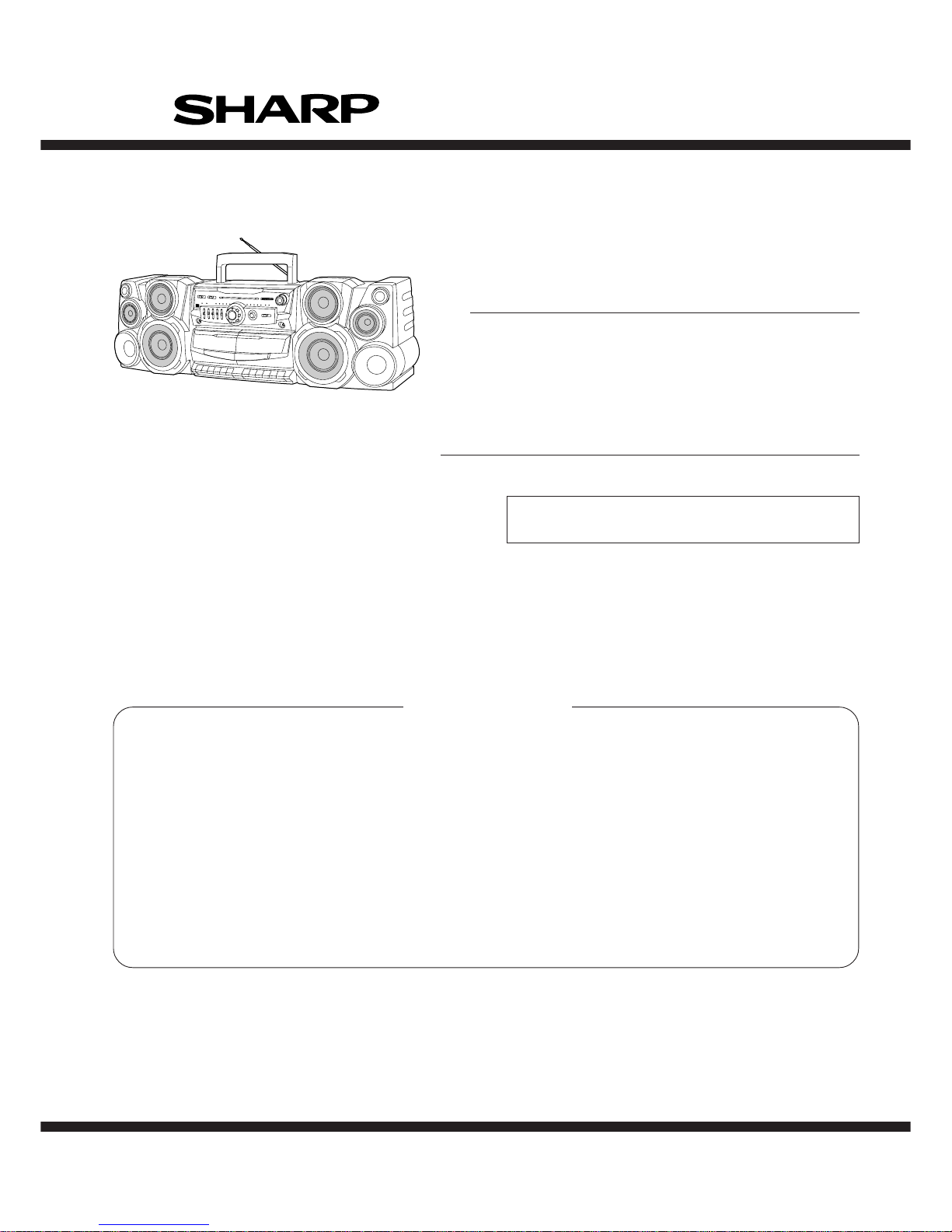
PORTABLE STEREO COMPONENT SYSTEM
MODEL WF-2100W(BK)
PORTABLE STEREO COMPONENT SYSTEM
MODEL WF-2100W(S)
Page 2
WF-2100W
– 2 –
FOR A COMPLETE DESCRIPTION OF THE OPERATION OF THIS UNIT, PLEASE REFER
TO THE OPERATION MANUAL.
VOLTAGE SELECTION
SPECIFICATIONS
General
Power source: AC 110-127 V/220-240 V,
50/60 Hz
DC 15 V [“D” size
(UM/SUM-1, R20 or HP-2)
battery × 10]
Power consumption: 33 W
Output power: MPO (Max.); 50 W (25 W +
25 W)
(AC operation)
RMS; 25 W (12.5 W + 12.5 W)
(DC operation, 10 % T.H.D.)
Input terminal: Mixing microphone; 1 mV/600 ohms
CD/LINE; 350 mV/47 kohms
Output terminal: Headphones; 16-50 ohms
(recommended; 32 ohms)
Dimensions: Width; 282 mm (11-1/8")
Height; 217 mm (8-9/16")
Depth; 207 mm (8-1/8")
Weight: 3.5 kg (7.7 lbs.) without batter-
ies
Radio section
Frequency range: FM; 88 - 108 MHz
SW1; 2.3 - 7.3 MHz
SW2; 7.3 - 22 MHz
MW; 526.5 - 1,606.5 kHz
Tape recorder section
Frequency response: 60 - 12,000 Hz (Normal tape)
Signal/noise ratio: 40 dB (TAPE 1, recording/playback)
50 dB (TAPE 2, playback)
Wow and flutter: 0.3 % (WRMS)
Motor: DC 9 V electric governor
Bias system: AC bias
Erase system: Magnet erase
Speaker section
Speakers:
7.5 cm (3") woofer × 1
9 cm (3-9/16") woofer × 1
Super tweeter × 1
5 cm (2") tweeter × 1
Maximum input power: 25 W
Rated input power: 12.5 W
Impedance: 8 ohms
Dimensions: Width; 235 mm (9-1/4")
Height; 235 mm (9-1/4")
Depth; 192 mm (7-9/16")
Weight: 2.0 kg (4.4 lbs.)/each
Before operating the unit on mains, check the preset voltage. If the voltage is different from your local voltage, adjust the voltage
as follows. Slide the selector with a screwdriver to the appropriate voltage number. (AC 110 - 127 V or AC 220 - 240 V).
Specifications for this model are subject to change without
prior notice.
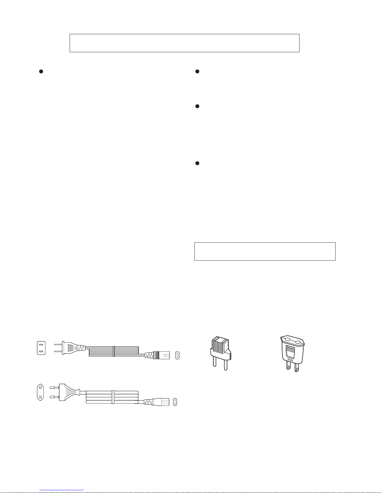
AC POWER SUPPLY CORD AND AC PLUG ADAPTOR
QACCA0004AW00
QACCE0007AW00
QPLGA0003AWZZ QPLGA0004AWZZ
Page 3
WF-2100W
– 3 –
NAMES OF PARTS
1
9
13
14
15
16
10
11
12
17 18 19 20 21
23 24 25 26 27
22
245678
28 29 30
31
32
33
34
36
37
38
39
40
35
1. Function Selector Switch
2. Power/(TAPE 2) Play Direction Indicators
3. Dubbing Speed/Built-in Microphone/FM Mode Switch
4. Graphic Equalizer Controls
5. Volume Control
6. Surround Switch (with Indicator)
7. Fine Tuning Control
8. Tuning Control
9. Built-in Microphone
10. Extra Bass Control
11. Headphone Socket
12. (TAPE 1) Cassette Compartment
13. FM Stereo Indicator
14. Band Selector Switch
15. Mixing Microphone Socket
16. (TAPE 2) Cassette Compartment
17. (TAPE 1) Record Button
18. (TAPE 1) Play Button
19. (TAPE 1) Rewind Button
20. (TAPE 1) Fast Forward Button
21. (TAPE 1) Stop/Eject Button
22. (TAPE 1) Pause Button
23. (TAPE 2) Reverse Mode Switch
24. (TAPE 2) Play Button
25. (TAPE 2) Fast Wind Buttons
26. (TAPE 2) Stop/Eject Button
27. (TAPE 2) Direction Switch
28. FM/SW Telescopic Rod Aerial
29. CD/Line Input Sockets
30. Beat Cancel Switch
31. Speaker Terminals
32. AC Voltage Selector
33. AC Power Input Socket
34. Battery Compartment
35. Woofer
36. Super Tweeter
37. Tweeter
38. Bass Reflex Duct
39. Speaker Release Lever
40. Speaker Wire
3
Page 4
WF-2100W
– 4 –
DISASSEMBLY
Caution on Disassembly
Follow the below-mentioned notes when disassembling
the unit and reassembling it, to keep it safe and ensure
excellent performance:
1. Take cassette tape out of the unit.
2. Be sure to remove the power supply plug from the wall
outlet before starting to disassemble the unit and remove
the batteries from the unit.
3. Take off nylon bands or wire holders where they need
to be removed when disassembling the unit. After
servicing the unit, be sure to rearrange the leads where
they were before disassembling.
4. Take sufficient care on static electricity of integrated
circuits and other circuits when servicing.
STEP REMOVAL PROCEDURE FIGURE
1 Front Cabinet/ 1. Screw .................. (A1) x9 4-1
Rear Cabinet 2. Socket ................. (A2) x1 4-3
3. Screw .................. (A3) x1
2 Main PWB/ 1. Knob.................... (B1) x1 4-2
Graphic Equalizer 2. Screw .................. (B2) x7
PWB/Fine Tuning 3. Socket ................. (B3) x4
PWB 4. Mic ...................... (B4) x1
3 Tape Mechanism 1. Open the cassette holder. 4-2
2. Screw .................. (C1) x5
4 Power PWB 1. Screw .................. (D1) x1 4-3
Figure 4-4
Figure 4-2
Figure 4-1
Figure 4-3
STEP REMOVAL PROCEDURE FIGURE
1 Woofer 1. Screw .................. (A1) x5 4-4
2. Front Panel ......... (A2) x1
3. Screw .................. (A3) x8
2 Tweeter 1. Screw .................. (B1) x2 4-4
MAIN UNIT
SPEAKER UNIT
Front
Cabinet
(A1)x1
ø3x8mm
Rear
Cabinet
(A1)x2
ø3x14mm
(A1)x1
ø3x8mm
(A1)x3
ø3x14mm
(A1)x1
ø3x30mm
(A1)x1
ø3x14mm
Front Cabinet
Washer
Nut
(B1)x1
(B2)x1
ø3x10mm
(B2)x4
ø3x8mm
(B2)x2
ø2.6x8mm
(C1)x5
ø3x10mm
Tape
Mechanism
(B3)x4
Cassette
Holder
Open
Graphic
Equalizer PWB
Fine Tuning PWB
(B4)x1
Main PWB
Rear
Cabinet
Power
Transformer
Power PWB
(D1)x1
ø3x8mm
(A3)x1
ø3x6mm
(A2)x1
Rod Antenna
Spring
Speaker
Release
Lever
Speaker Cord
Holder
Speaker
Cord
Driver
(A2)x1
Woofer
Woofer
Tweeter
(A3)x4
ø3x8mm
(A3)x4
ø3x8mm
(B1)x2
ø3x8mm
(A1)x5
ø4x16mm
Main Unit
Speaker Box
MAIN UNIT SPEAKER UNIT
Page 5
WF-2100W
– 5 –
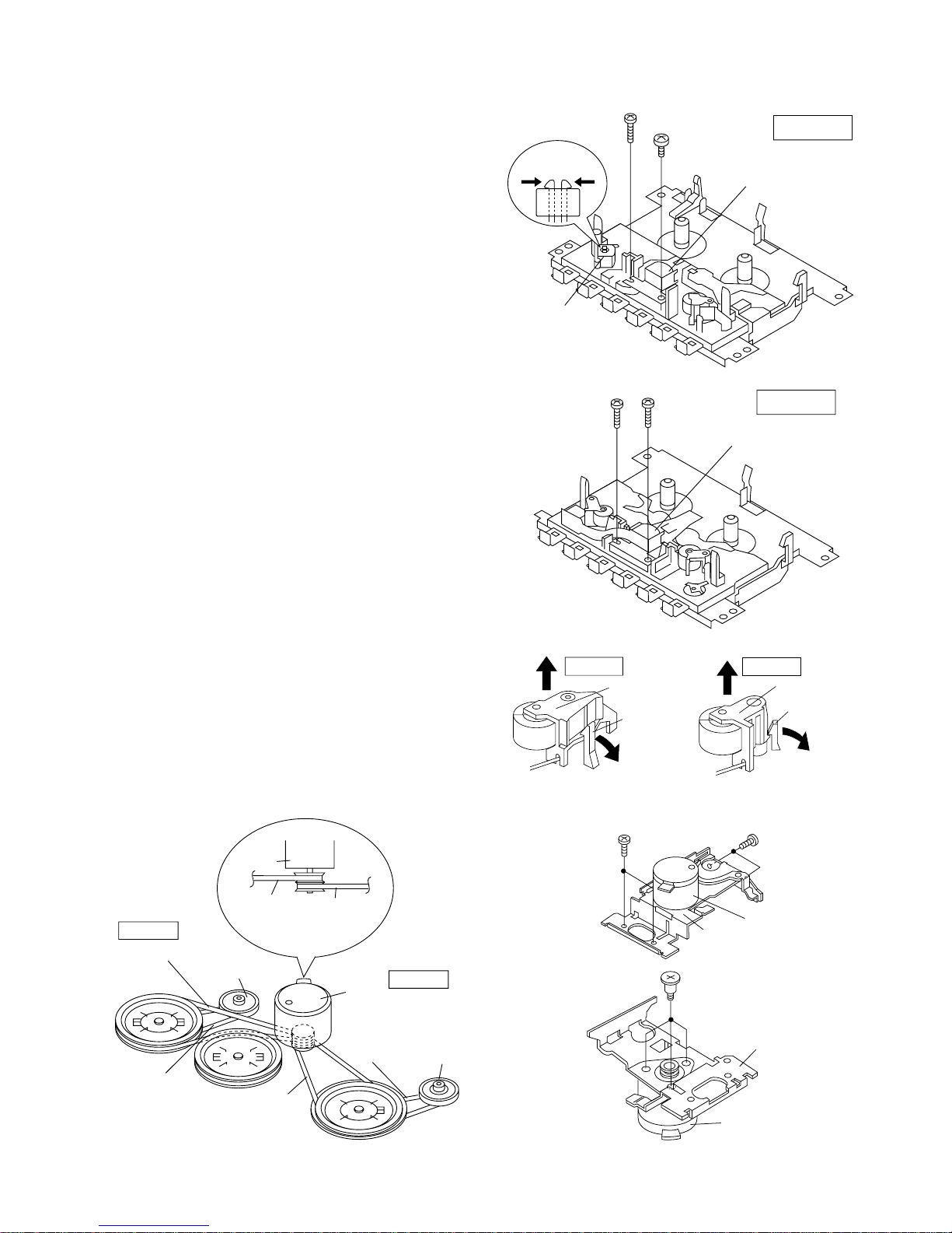
REMOVING AND REINSTALLING THE MAIN PARTS
Figure 5-5
Figure 5-4
Record/Playback
Head
Erase
Head
(A1)x1
ø2x3mm
(A1)x1
ø2x7mm
Hook
(A2)x2
TAPE 1
TAPE 2
(B1)x1
ø2x6mm
(B1)x1
ø2x6mm
Playback
Head
Pinch Roller
(C2)x1
TAPE 2
Pinch Roller
Pawl
Pinch Roller
(C1)x1
Pinch Roller
Pawl
TAPE 1
<A>
<B>
<A>
<B>
Figure 5-1
Figure 5-2
Figure 5-3
Motor
(D2)x3
Special Screw
Motor
Bracket
(D1)x2
ø2x4mm
(D1)x2
ø2x4mm
Motor
Motor
Bracket
TAPE 2
TAPE 1
TAPE 2
Main Belt
(F1)x1
TAPE 1
Main Belt
(E1)x1
Motor
Motor
REW/FF
Clutch Ass'y
REW/FF
Clutch Ass'y
Main
Belt
(E1)x1
Main
Belt
(F1)x1
REW/FF
Belt
(F2)x1
REW/FF
Belt
(E2)x1
TAPE MECHANISM SECTION
Perform steps 1, 2 and 3 of the disassembly method to
remove the tape mechanism. (See page 4.)
How to remove the record/playback and erase
heads (TAPE 1) (See Fig. 5-1)
1. When you remove the screws (A1) x 2 pcs., the recording/
playback head can be removed.
2. Move the hooks (A2) x 2 pcs., toward the center position as
shown in Fig. 5-1 and then lift the erase head.
How to remove the playback head (TAPE 2)
(See Fig. 5-2)
1. When you remove the screws (B1) x 2 pcs., the playback
head can be removed.
How to remove the pinch roller (TAPE 1/2)
(See Fig. 5-3)
1. Carefully bend the pinch roller pawl in the direction of the
arrow <A>, and remove the pinch roller (C1) x 1 pc. and
(C2) x 1 pc., in the direction of the arrow <B>.
Note:
When installing the pinch roller, pay attention to the spring
mounting position.
How to remove the motor (See Fig. 5-4)
1. Remove the belt.
2. Remove the screws (D1) x 4 pcs., to remove the motor
bracket.
3. Remove the screws (D2) x 3 pcs., to remove the motor.
How to remove the belt (TAPE 1)
(See Fig. 5-5)
1. Remove the main belt (E1) x 1 pc., from the motor side.
2. Remove the FF/REW belt (E2) x 1 pc.
How to remove the belt (TAPE 2)
(See Fig. 5-5)
1. Remove the main belt (F1) x 1 pc., from the motor side.
2. Remove the FF/REW belt (F2) x 1 pc.
Page 6
WF-2100W
– 6 –
FM IF T108 Input: FM Antenna
FM Detection T106
Output: Pin 9 of IC102
FM Band fL: L101 Input: Antenna
Coverage fH: TC1 Output: Headphones
Socket
FM Tracking fL (88.0 MHz): L102
(Load resistance: 32 ohms)
fH (108 MHz): TC2
ADJUSTMENT
Specified Value
MECHANISM SECTION
• Driving Force Check
Specified Value
• Torque Check
• Head Azimuth
MTT-114 Headphones Socket
(Load resistance: 32 ohms)
Instrument Connection
• Tape Speed (Normal only)
Instrument
Connection
MTT-111 Tape 1, Tape 2: 3,000 ± 60 Hz Headphones
VR501 Socket
(Load resistance:
32 ohms)
Torque Meter
Torque Meter
Test Tape
Test Tape
• Playback Amplifier Sensitivity Check
Play: TW-2412 Tape 1: Over 60 g
Tape 2: Over 50 g
Tape 1 Tape 2
Adjustment
Point
Specified
Value
Specified value Instrument Connection
MTT-118 2.5 V ± 3 dB Speaker terminal
(Load resistance: 8 ohms)
Test tape
Figure 6 VCO FREQUENCY TEST CIRCUIT
TUNER SECTION
fL: Low-range frequency
fH: High-range frequency
Specified value Instrument Connection
VR102 76 kHz ± 200 Hz Pin 13, Pin 21 and ground
of IC102
Adjustment
Point
• VCO Frequency
Note:
After preparing the test circuit shown in Fig. 6, connect the Pin
13, Pin 21 and ground of the IC102 with the test circuit, and
measure the value.
Specified Value/
Adjusting Point
Test Stage
Instrument
Connection
Test Stage
Specified Value/
Adjusting Point
Instrument
Connection
AM IF T107 Input: Antenna
Output: Pin 9 of IC102
MW Band fL: T103 Input: Antenna
Coverage fH: TC3 Output: Headphones
Socket
MW Tracking fL (600 kHz): L103
(Load resistance 32 ohms)
fH (1,400 kHz): TC4
SW1 Band fL (2.3 MHz): T104
Coverage fH (7.3 MHz): CT102
SW1 fL (2.6 MHz): T101
Tracking fH (6 MHz): CT104
SW2 Band fL (7.3 MHz): T105
Coverage fH (22 MHz): CT101
SW2 fL (8.5 MHz): T102
Tracking fH (19 MHz): CT103
10 pF
1 Mohm
10 kohm
TO FREQUENCY
COUNTER
Pin 13 of IC102
Pin 21 of IC102
FET: 2SK212
(or Other 2SK Type FET.)
G
D
S
0.1 µF
Specified Value
Beat Cancel A: 100 ± 4 kHz
B: 94 ± 4 kHz
C: 104 ± 4 kHz
T201 100 kHz + 4 kHz Pin 5 of CON202
Adjustment Point Specified value Instrument
Connection
DECK SECTION
• Bias Oscillation
• FM IF/RF
Play: TW-2111 30 to 70 g.cm 27 to 60 g.cm
Fast Forward: TW-2231 Over 55 g.cm 55 to 120 g.cm
Rewind: TW-2231 Over 55 g.cm 55 to 120 g.cm
• AM IF/RF
• Beat Cancel Switch: A
Page 7
WF-2100W
– 7 –
Figure 7 ADJUSTMENT POINTS
FM DET.
VCO
CT101
CT102
CT103
CT104
fH fL
SW2 BAND
COVERAGE
fH
fH
fL
fL
FM
TRACKING
SW2
TRACKING
MW
TRACKING fL
MW
TRACKING fH
fL
fH
fH
fL
SW1
TRACKING
MAIN PWB
fHfL
FM BAND
COVERAGE
MW BAND
COVERAGE fL
MW BAND
COVERAGE fH
SW1 BAND
COVERAGE
VR102
IC102
T106
T105
T103
T102
T101
T104
TC2
TC1
TC3
TC4
L102
L101
L103
T107
T108
AM IF
FM IF
13
21
9
MAIN PWB
SW202
T201
VR501
BIAS
OSC.
TAPE
SPEED
Page 8
WF-2100W
– 8 –
NOTES ON SCHEMATIC DIAGRAM
• Resistor:
To differentiate the units of resistors, The symbol as K and
M are used: the symbol K means 1000 ohm and the symbol
M means 1000 kohm and the resistor without any symbol
is an ohm resistor. The resistor designated “Fusible” is a
fuse type resistor.
• Capacitor:
To indicate the unit of capacitor, a symbol P is used: this
symbol P means pico-farad and the unit of the capacitor
without such a symbol is microfarad. As to electrolytic
capacitor, the expression “capacitance/withstand voltage”
is used.
(CH),(RH),(UJ): Temperature compensation
(ML): Mylar type
(S): Styrol type
• The indicated voltage in each section is the one measured
by Digital Multimeter between such a section and the
chassis with no signal given.
• Schematic diagram and Wiring Side of P.W. Board for this
model are subject to change for improvement without prior
notice.
• Parts marked with “ ” ( ) are important for
maintaining the safety of the set. Be sure to replace these
parts with specified ones for maintaining the safety and
performance of the set.
SW1 TAPE 2 DIRECTION A—B
SW2 TAPE 1 PLAY ON—OFF
SW3 TAPE 1 FF/REW ON—OFF
SW4 TAPE 1 REC ON—OFF
SW5 TAPE 2 PLAY ON—OFF
SW6 TAPE 2 FF/REW ON—OFF
SW101 BAND SELECTOR SW2—SW1—MW—FM
SW202 BEAT CANCEL A—B
SW203 DUBBING SPEED/MIC/ HIGH—NORMAL—MIC/
FM MODE
FM STEREO—FM MONO
SW401 SURROUND ON—OFF
SW501 FUNCTION SELECTOR/ CD/LINE—RADIO—
POWER TAPE/STAND-BY—ON
SW601 VOLTAGE SELECTOR
110-127 V—220-240 V
REF. NO.
DESCRIPTION
POSITION
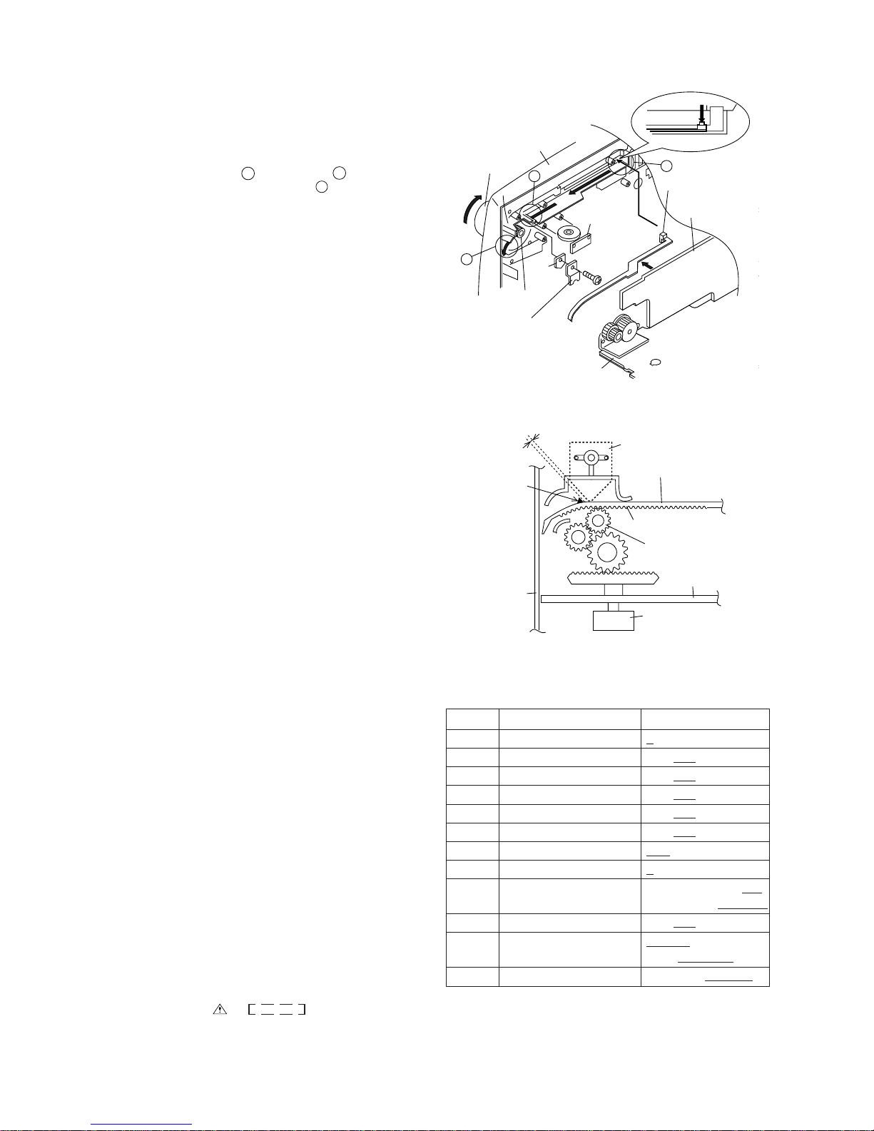
FITTING OF DIAL POINTER
A
B
C
Figure 8-1
1. Remove the Main PWB, the Graphic Equalizer PWB and
the Fine Tuning PWB. (See Figure 4-2 in the "Disassembly" on page 4.)
2. Remove the dial pointer guide and PWB.
3. Insert the dial pointer from , lead it under , hang it on
the tuner gear and then pass it through .
4. Replace the Main PWB, the Graphic Equalizer PWB and
the Fine Tuning PWB.
5. Rotate the tuning knob in the arrow direction until it stops.
(Set the tuner variable capacitor to "0" point (F-LOW
state).)
6. Adjust the dial pointer so that its stopper becomes the
Figure 8-2 position. (Adjust the engagement of the pointer
gear and the tuner gear to get the minimum space between
the PWB and the stopper.) This position is the "0" point.
7. Screw up the PWB and the dial pointer guide.
Figure 8-2
Tuning Knob
Front Cabinet
C
A
Dial Pointer(207)
Tuner
Gear
PWB
Dial Pointer Guide
(256)
Main PWB
Graphic Equalizer
PWB
Fine Tuning
PWB
Screw(605)
ø3x8mm
B
Dial Pointer(207)
"0" Point
Tuner Gear
Stopper
Main PWB
Variable Capacitor
Dial Pointer
PWB
Make the minimum space.
Front Cabinet
Pointer Gear
Page 9

WF-2100W
– 9 –
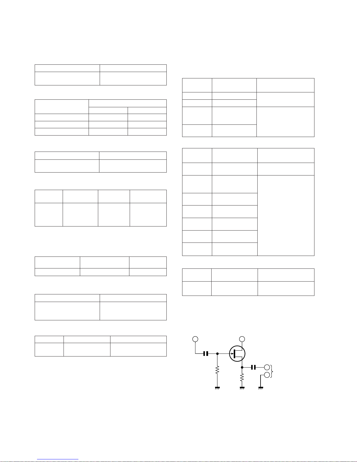
TYPES OF TRANSISTOR AND LED
ECB
FRONT
VIEW
B
E
C
TOP
VIEW
L01-224HD2SC2412 KR
KTC3875 GR
2SC945 AP
3DA8050
SS8550
SS8050
FRONT
VIEW
VOLT AGE
PIN
NO.
VOLTAGE
1 0.98 V
1.7 V
6.12 V
0 V
0 V
6.15 V
1.6 V
5.46 V
6.1 V
IC101
9
8
7
6
5
4
3
2
PIN
NO.
VOLTAGE
1 1.59 V
1.6 V
6.15 V
0.19 V
1.6 V
0 V
6.4 V
0 V
2.3 V
10 2.3 V
11 5.4 V
12 0.9 V
13 1.1 V
14 2.1 V
15 1 V
16 1.7 V
17 1.56 V
18 1.58 V
19 0.43 V
20 6.1 V
21 6.1 V
22 0.53 V
23 1.6 V
24 1.41 V
IC102
9
8
7
6
5
4
3
2
PIN
NO.
VOLTAGE
1 6.3 V
1.6 V
1.6 V
0 V
3.4 V
3.45 V
3.5 V
6.8 V
IC202
8
7
6
5
4
3
2
PIN
NO.
VOLTAGE
1 5.5 V
5.5 V
6.1 V
6.1 V
5.5 V
5.5 V
6.1 V
6.1 V
5.5 V
10 5.5 V
11 6.1 V
12 6.1 V
13 5.5 V
14 5.5 V
15 6.1 V
16 6.1 V
17 4.1 V
18 2.4 V
19 2.4 V
20 4.1 V
21 3 V
22 3 V
23 6.5 V
24 0 V
IC301
9
8
7
6
5
4
3
2
PIN
NO.
VOLTAGE
10 V
0 V
1.28 V
1.28 V
1.37 V
1.32 V
0 V
0 V
1.83 V
10 1.28 V
11 0 V
12 0 V
13 0.85 V
14 0 V
15 1.28 V
16 1.83 V
17 1.45 V
18 6.6 V
19 4.6 V
20 1.37 V
21 1.28 V
22 1.28 V
23 0 V
24 0 V
IC201
9
8
7
6
5
4
3
2
PIN
NO.
VOLTAGE
1 14.4 V
0 V
0 V
0 V
4.53 V
0 V
15 V
15 V
6.86 V
10 0 V
11 6.86 V
12 6.85 V
13 0 V
14 6.85 V
IC402
9
8
7
6
5
4
3
2
PIN
NO.
VOLTAGE
1 3.58 V
3.58 V
3.58 V
0 V
3.58 V
3.58 V
3.58 V
7.1 V
IC401
8
7
6
5
4
3
2
PIN
NO.
VOLTAGE
1 15 V
0 V
7.99 V
IC403
3
2
PIN
NO.
VOLTAGE
1 15 V
0 V
8.99 V
IC404
3
2
PIN
NO.
VOLTAGE
B0 V
0 V
0 V
Q301
E
C
PIN
NO.
VOLTAGE
B0 V
0 V
0 V
Q302
E
C
PIN
NO.
VOLTAGE
B 0.7 V
0 V
0 V
Q201
E
C
PIN
NO.
VOLTAGE
B 0.7 V
0 V
0 V
Q202
E
C
PIN
NO.
VOLTAGE
B 0.7 V
0 V
0 V
Q203
E
C
PIN
NO.
VOLTAGE
B 0.7 V
0 V
0 V
Q204
E
C
PIN
NO.
VOLTAGE
B 0.6 V
4.3 V
0.2 V
Q205
E
C
PIN
NO.
VOLTAGE
B 0.7 V
0 V
0 V
Q206
E
C
PIN
NO.
VOLTAGE
B 7.2 V
8 V
8 V
Q207
E
C
PIN
NO.
VOLTAGE
B0 V
0 V
0 V
Q208
E
C
PIN
NO.
VOLTAGE
B 0.93 V
2.25 V
0.31 V
Q209
E
C
PIN
NO.
VOLTAGE
B 0.93 V
2.25 V
0.31 V
Q210
E
C
PIN
NO.
VOLTAGE
B 0.7 V
0 V
0 V
Q212
E
C
PIN
NO.
VOLTAGE
B 0.7 V
0 V
0 V
Q218
E
C
PIN
NO.
VOLTAGE
B 0.7 V
0 V
0 V
Q219
E
C
PIN
NO.
VOLTAGE
B5 V
4.3 V
5 V
Q213
E
C
PIN
NO.
VOLTAGE
B 0.7 V
0 V
0 V
Q220
E
C
PIN
NO.
VOLTAGE
B 0.7 V
0 V
0 V
Q221
E
C
PIN
NO.
VOLTAGE
B0 V
7.42 V
0 V
Q505
E
C
PIN
NO.
VOLTAGE
B 0.69 V
0 V
0 V
Q506
E
C
PIN
NO.
VOLTAGE
B8 V
7.5 V
5.85 V
Q504
E
C
Page 10

WF-2100W
– 10 –
A
B
C
D
E
F
G
H
1
2
34 5
6
• NOTES ON SCHEMATIC DIAGRAM can be found on page 8.
Figure 10 SCHEMATIC DIAGRAM (1/2)
D101
1N4148
D102
1N4148
SW101-C
BAND
SELECTOR
SW101-F
BAND
SELECTOR
IC101
LA1186N
FM FRONT END
BAND PASS
FILTER
BP101
C101
0.001
C104
0.001
L102
C106
15P(CH)
VC2
TC2
C102
0.001
R122
10
C103
10/16
C139
0.022
D103
1N4148
C140
0.1
T108
R102
33
C107
15P(CH)
VC1
TC1
C108
20P(CH)
L101
C109
5P(CH)
R103
220K
R104
820K
C110
0.022
C138
220/16
C137
0.022
C142
330P(CH)
T106
R101
100
R105
100
L103
T101
T102
C143
15P
(CH)
TC4
SW101-E
BAND
SELECTOR
R121
3.9K
CT104
10P
CT103
10P
C144
5P(CH)
VC3
CF101
C136
0.0022
(ML)
R120
2.7K
C135
0.0082(ML)
C133
3.3/50
C134
470P
C131
0.0015(ML)
R119
15K
VR102
10K(B)
SW203-B
DUBBING
SPEED
C132
3.3/50
R118
100K
IC102
C121
0.022
C123
0.022
C124
22/16
CF102
T107
R125
100K
R123
1.2K
C125
0.0082
C126
0.0082
C127
1/50
R113
27K
R114
4.7K
R116
4.7K
R115
27K
C128
1/50
R117
10
C129
1/50
C130
0.022
R126
100
VD101
1S2638
C116
0.022
R106
100K
R108
10K
C117
0.022
R107
100K
CON101
CN101
SW101-D
BAND
SELECTOR
C115
5P
(CH)
VC4
C112 30P(CH)
C111
330P(CH)
C105
8P(CH)
C113
0.0015(ML)
C114
0.0047(ML)
TC3
CT102
10P
CT101
10P
C118
0.022
R111
47
R110
47
T103
T104
T105
SW101-A
BAND
SELECTOR
R112
47
C119
0.022
C120
10/16
C122
0.022
R109 22K
VR101
100K(B)
IC102
LA1805
FM/AM IF MPX.
SW501
-
FUNCTI
O
SELECT
O
S
F
U
S
E
R266
4.7K
R265
4.7K
R264
47K
R263
47K
JK202
LINE INPUT
D201
1N4148
R259
220
C280
1/50
R230
10K
R261 18K
R262 18K
MIC1
BUILT-IN
MICROPHONE
JK201
MIC
CN206
IC202
BA15218F
MIC AMP.
R273
2.2K
C243
2.2/50
R271
1K
Q208
SS8050
R274
10K
C245
220/16
C260
150P
C247
150P
C248
100P
R248
270
R281
10K
R249
33K
C263
100/16
C281
10/16
R275
4.7K
R272
1M
D212
1N4148
R252
3.3K
C242
1/50
R241
2.2K
D203
1N4148
C244
10/16
R200
4.7K
R242
560
R243
10K
Q203
2SC945 AP
R254
10K
SW203-A
DUBBING
SPEED
D211
1N4148
D202
1N4148
R290
10K
R285
22K
R255
4.7K
Q212
KTC3875 GR
R256
22K
R283
10K
Q207
SS8550
D205
1N4148
C249
100/16
R299
10K
R298
10K
R260
10K
C250
100/16
C251
100/16
D207
1N4148
D209
1N4148
C257
47/16
D510
1N4148
D509
1N4148
R245
10K
R232
10K
SW501-A
FUNCTION
SELECTOR
R229
2.2K
Q206
KTC3875 GR
D213
1N4148
R225
47K
C518
0.0027(ML)
R508
3.9K
R509
330
Q504
SS8550
R510
100K
Q505
2SC2412 KR
Q506
2SC2412 KR
VR501
500(B)
C509
100/16
R514
10K
C508
0.022
R224
47K
C517
0.0027(ML)
R222
12K
R512
10K
R511
10K
R226
10K
R227
10K
C262
100/16
C288
330/16
R217
100K
R215
1.2K
R218
100K
R216
1.2K
R250
3.3K
R251
3.3K
Q202
2SC2412 KR
Q201
2SC2412 KR
C225
10/16
R253
22K
R228
2.2K
D214
1N4148
R279
150
Q213
SS8550
R280
56K
D215
1N4148
R277
33K
D216
1N4148
R282
10K
D218
1N4148
C222
2.2/50
C220
0.001
R214
470K
C270
0.015
C218
10/16
R247
390
R212
1K
C253
0.0022(ML)
R210
180K
C267
330P
C230 47/16
R221 1M
C221
2.2/50
C219
0.001
R257
150
R220
10K
R213
470K
R244
390
C271
0.015
C217
10/16
R209
180K
R211
1K
C246
0.0022(ML)
R219
12K
C252
47/16
C213
2.2/50
C223
2.2/50
C224
330/16
Q204
KTC3875 GR
C261
82P
C228
0.0015
L202
47mH
R235
15K
C216
2.2/50
R284
47K
R206
180K
R208
5.6K
C214
2.2/50
R204
4.7K
C210
0.033
(ML)
R202
47
R520
56K
C208
22/16
C204
220P
C206
220P
R205
180K
C205
220P
C203
220P
C207
22/16
R207
5.6K
R521
56K
R201
47
C209
0.033
(ML)
R203
4.7K
IC201
IC201
TA8189N
RECORD/
PLAYBACK AMP.
C202
470P
C201
470P
R296
1K
R297
1K
R276
1K
R278
1K
R288
1K
R289
1K
C232
820P
CON201CON202
R237
47K
Q220
KTC3875 GR
Q221
KTC3875 GR
R236
47K
C231
820P
Q217
KTC3875 GR
R295
4.7K
R294
3.3K
R293
3.3K
R292
4.7K
D219
1N4148
Q218
KTC3875 GR
Q219
KTC3875 GR
Q216
KTC3875 GR
L201
47mH
R234
15K
C215
2.2/50
C227
82P
C226
0.0015
C234
150P
C233
150P
SW202-A
BEAT
CANCEL
C235
180P(CH)
C237
0.0022(ML)
D217
1N4148
R287
1.8K
Q205
3DA8050
R239
10
C240
0.0022(ML)
C239
0.001(ML)
R238
33K
C238
0.022(ML)
C241
100/16
T201
BIAS OSC.
R286
47K
R240
2.2K
R223
12K
R131
10K
R129
3.3K
R128
33K
C269
10/16
R524
4.7K
L203
2.7mH
L204
2.7mH
C268
330P
FM/SW ROD
ANTENNA
FM
MW
SW1
SW2
FM
MW
SW1
SW2
1
2
3
1
2
3
1
2
3
123456789
FM IF
SW2
SW1
MW
FM
24 23 22 21 20 19 18 17 16 15 14 13
121110
987654321
TP5
TP3
TP4
TP2
TP1
FM(ST)/
HIGH
FM(ST)/
NORMAL
FM(MONO)/
MIC
AM
OSC
STB
+VCC
AM
RF
FM
DET
DET
OUT
AM IN
IF AD
MPX IN
MO/ST
VCO
NC
AM/FM
R-CH
L-CH
GND
GND
AM IF
AGCAMMIX
FM IF
IN
SW101-B
BAND SELECTOR
FM
MW
SW1
SW2
132
132
FM
MW
SW1
SW2
FM
MW
SW1
SW2
FINE
TUNING
FINE TUNING
PWB-A3
CD/LINE
(ON)
RADIO
(ON)
TAPE
(STAND-BY)
CD/LINE
(ON)
RADIO
(ON)
TAPE
(STAND-B
Y
R-CH
L-CH
CD/LINE_IN(R)
CD/LINE_IN(L)
MIC_OUT(R)
MIC_OUT(L)
1
2
GND
5
6
7
8
4
3
2
1
VCC
GND
FM(ST)/HIGH
FM(ST)/
NORMAL
FM(MONO)/
MIC
CD/LINE
(ON)
RADIO
(ON)
TAPE
(STAND-BY)
TAPE
SPEED
1234567 89
10 11 12
131415161718192021222324
CH2/A
CH2/B
MATAL
OUT
PRE
OUT
MIX
OUT
REC
OUT
NF
GND1
M/N
GNDALC
VCC
A/B
NF
CH1/B
CH1/A
RECINRECNFREC
OUT
PRE
OUT
MATAL
OUT
RECNFREC
IN
3
2
1
3
2
1
5
4
1
2
3
5
4
1
2
3
AB
R-CH
R-CH
L-CH
L-CH
SIDE-A
SIDE-B
SIDE-A
SIDE-B
A
A
B
B
TAPE 2
PLAYBACK HEAD
TAPE 1
RECORD/PLAYBACK HEAD
ERASE HEAD
SW1-A
TAPE 2
DIRECTION
SW1
TRACKING
fHfLCT104
T101
SW1 BAND
COVERAGE
fHfLCT102
T104
MW
TRACKING
SW2 BAND
COVERAGE
fHfLCT101
T105
MW BAND
COVERAGE
SW2
TRACKING
fHfLCT103
T102
+B
+B
+B
MW BAR ANT.
SW1 ANT.
SW2 ANT.
MW OSC.
SW1 OSC.
SW2 OSC.
AM IF
FM DET.
FM
TRACKING
FM
OSC.
VCO
FM SIGNAL
MW/SW1/SW2 SIGNAL
PLAYBACK SIGNAL
RECORD SIGNAL
MIC SIGNAL
CD/LINE SIGNAL
Page 11

WF-2100W
– 11 –
Figure 11 SCHEMATIC DIAGRAM (2/2)
78 9101112
0V
0V
0V
0V
14.2V
6.9V
6.9V
6.9V
6.9V
0V
0V
10.7 V 10.7 V 10.7 V 10.7 V 10.7 V0 V 0 V 0 V 7 V
2.1 V 2.1 V 2.1 V 2.1 V 2.1 V0 V 2.4 V 0 V 7 V
SW501-C
FUNCTION
SELECTOR
SW501-D
FUNCTION
SELECTOR
C254
2.2/50
C258
220P
R267
330K
R233
270
Q209
2SC945 AP
R269
3.9K
C256
2.2/50
C236
220/16
R270
3.9K
C229
2.2/50
C259
220P
R231
270
Q210
2SC945 AP
C255
2.2/50
R268
330K
R258
560
CN203CN204
SW501-B
FUNCTION
SELECTOR
CON401
SPEAKER
TERMINALS
C428
0.1(ML)
R428
2.2
R426
2.2
C426
0.1(ML)
C427
0.1(ML)
R427
2.2
C425
0.1(ML)
R425
2.2
IC402
LA4663
POWER AMP.
JK401
HEADPHONES
R430
220
R429
220
C430
10/16
C429
10/16
C422
0.022
R431
15K
C419
2.2/50
R421
1K
C424
47/25
R432
15K
C417
0.001
C418
0.001
C420
2.2/50
R422
1K
R415
3.3K
C413
0.001
C415
0.15(ML)
R419
3.3K
R417
22K
R420
3.3K
C416
0.15(ML)
C414
0.001
R416
3.3K
R418
22K
C409
2.2/50
C410
2.2/50
CON501
D401
1N4148
R433
15K
C501
33/50
C502
0.1
IC403
L7808CV
VOLTAGE
REGULATOR
IC404
L7809CV
C514
1/50
C512
47/16
C516
0.1
VOLTAGE
REGULATOR
C515
1/50
IC401(1/2)
KIA4558P
OPE AMP.
IC401(2/2)
KIA4558P
OPE AMP.
R410
12K
R408
12K
C408
4.7/50
R406
2.7K
C406
0.0033
C412
47/16
C411
100/16
R413
10K
R412
10K
C407
4.7/50
R407
12K
R405
2.7K
C405
0.0033
R409
12K
R403
10K
R404
10K
C404
2.2/50
C403
2.2/50
R401
100K
C401
0.015(ML)
R402
100K
C402
0.015(ML)
47K
C518
0.0027(ML)
C511
47/16
L501
47µH
C505
47/16
C506
47/16
R519
10K
R513
10K
R523
10K
R522
10K
D504
1N4148
D506
1N4148
D508
1N4148
D503
1N4148
CON502
R411
330
M1
TAPE
MOTOR
SW1-B
TAPE 2
DIRECTION
SW2
TAPE 1
PLAY
SW3
TAPE 1
FF/REW
SW6
TAPE 2
FF/REW
SW4
TAPE 1
REC
SW5
TAPE 2
PLAY
R507
47K
R508
3.9K
R509
330
Q504
SS8550
501
0(B)
47K
C517
0.0027(ML)
IC301
BA3822LS
GRAPHIC EQUALIZER
R331
180K
R330
180K
C335
1/50
C325
1/50
R305
2.2K
C305
1/50
VR305-A
100K(B)
VR305-B
100K(B)
VR304-A
50K(B)
VR304-B
50K(B)
VR303-A
100K(B)
VR303-B
100K(B)
VR302-A
100K(B)
VR302-B
100K(B)
VR301-A
50K(B)
VR301-B
50K(B)
R308
1K
C302
2.2/50
C334
220/16
R307
220
R301
1K
C301
2.2/50
R303
2.2K
C303
0.022
R309
1K
R318
1K
C323
4.7/50
C307
1/50
C308
0.022
C311
0.33/50
C312
0.0056
C315
0.1
C320
820P(CH)
C322
0.022
C319
0.018
C321
1/50
C318
0.0056
C317
0.33/50
C313
0.1(ML)
C310
820P(CH)
C309
0.018
C324
4.7/50
C306
1/50
R306
2.2K
R310
1K
R304
2.2K
C304
0.022
LD314
L01-224HD
SW401
SURROUND
LD311
L01-224HD
LD312
L01-224HD
R333
1K
LD313
R319
330
R302
10K
Q302
KTC3875 GR
IC303
LB1403N
METER DRIVER
IC302
LB1403N
METER DRIVER
R313
10K
R314
120
Q301
KTC3875 GR
C326
0.001
C329
10/16
C328
10/16
R315
12K
R316 10K
R3201KR3211KR3241KR3251KR326
1K
LD301
L01-224HD
R327
1K
LD306
L01-224HD
LD302
L01-224HD
LD303
L01-224HD
LD304
L01-224HD
LD305
L01-224HD
R3281KR3341KR3351KR336
1K
LD307
L01-224HD
LD308
L01-224HD
LD309
L01-224HD
LD310
L01-224HD
R323
10K
C333
10/16
R322
12K
R329
120
C330
10/16
C331
0.001
VR401-A
50K(B)
VR401-B
50K(B)
CN205B
CN205A
CN501
D601
1N5402
D603
1N5402
D604
1N5402
D602
1N5402
C604
0.022
C602
0.022
C601
0.022
C603
0.022
F601
T4A L 250V
SO601
AC INLET
SOCKET
T601
POWER
TRANSFORMER
SW601
VOLTAGE
SELECTOR
D511
1N4148
D501
1N4148
R312
3.3K
C314
0.0033
R317
1K
R311
3.3K
C316
0.0033
CD/LINE
(ON)
RADIO
(ON)
TAPE
(STAND-BY)
CD/LINE
(ON)
RADIO
(ON)
TAPE
(STAND-BY)
616
1
L_IN
R_IN
CD/LINE
(ON)
RADIO
(ON)
TAPE
(STAND-BY)
+
+
–
–
+
–
+
–
–
+
+
–
–
+
–
–
–
+
+
+
TWEETER
8 OHM
SUPER
TWEETER
SUPER
TWEETER
TWEETER
8 OHM
WOOFER
16 OHM
WOOFER
16 OHM
WOOFER
16 OHM
WOOFER
16 OHM
L-CHR-CH
L-CH
R-CH
14
13
12
10
11
9
875
4
1
1
4
3
2
7
3
6
2
+OUT1
+OUT2
-OUT1
-OUT2
R_OUT
L_OUT
R_OUT
4653271
4653271
MIC MUTE
L_IN
R_IN
121
2
R_OUT
13
2
GND
OUT IN
13
2
GND
OUT IN
–
+
8
6
5
–
+
123456789
10 11 12 13
123456789
10 11 12 13
M
A
B
PE
EED
MAIN PWB-A1
23 21 18 17 15 13 11
97531
123456789
123456789
24 22 20 19 16 14 12 10
8642
(10kHz)
(10kHz)
(100Hz)
(100Hz)
(500Hz)
(500Hz)
(1kHz)
(1kHz)
(5kHz)
(5kHz)
X-BASS
GRAPHIC EQUALIZER
X-BASS
GRAPHIC EQUALIZER
11
77
ON OFF
VOLUME VOLUME
L_OUT
L_IN
TONE
R_OUT
R_IN
TONE
GND
GRAPHIC EQUALIZER
PWB-A2
MUTE
SIDE A LED
SIDE B LED
GND
SURROUND ON
SURROUND ON
ST LED
R_IN
GND
+8V
R_OUT
L_OUT
L_IN
BATTERY A
PWB-A4
BATTERY B
PWB-A5
POWER PWB-B
BATTERYES DC15V
["D" SIZE(UM/SUM-1.
R20 or HP2)
BATTERY x 10]
AC 110-127V/
220-240 V,
50/60 Hz
AC 110-127 V
AC 220-240 V
T102
104
MW
TRACKING
fHfLTC4
L103
T101
105
MW BAND
COVERAGE
fHfLTC3
T103
FM
TRACKING
fHfLTC2
L102
FM BAND
COVERAGE
fHfLTC1
L101
IC302, IC303: VOLTAGE
PIN 123456789
LED OFF
LED ON
+B
+B
+B
+B
+B
+B
+B +B +B
+B
+B
+B
+B
+B
+B+B
+B
+B
+B
+B
+B +B
+B+B
+B
+B +B
HL +–
AC POWER
SUPPLY CORD
Page 12

WF-2100W
– 12 –
A
B
C
D
E
F
G
H
1
2
34 5
6
Figure 12 WIRING SIDE OF P.W.BOARD (1/3)
CN101
VR101
1
2
3
13
12
11
10
9
8
7
6
5
4
3
2
1
R309
R333
R312
C324
C313
LD313
R313
R302
R322
R329
R317
R318
IC301
VR401
R331
R330
C335
C329
IC302
C333
C311
C307
R303
R311
R305
R306
R304
LD312
LD311
LD306
LD307
LD308
LD309
LD310
LD305
LD304
LD303
LD302
C305
C321
C317
VR304
VR303
VR302
VR301
VR305
C306
C323
R310
10kHz
5kHz
1kHz
500Hz
100Hz
SW401
SURROUND
C328
C302
C301
C334
R307
R308
C330C325
R314
IC303
CN205B
CN203
2
1
1
1
7
6
5
10
15
20
24
23
R319
CN204
LD301
9
8
7
6
5
4
3
2
1
LD314
BL
YL
BR
BK
RD
BK
WH
1
7
FM/SW ROD ANTENNA (257)
(261)
BK
RD
GR
YL
GY
BL
YL
RD
VL
GR
WH
RD
OR
PLAYBACK
HEAD
SW1
DIRECTION
HEAD FLEXIBLE
PWB
B
A
1
2
3
WHBKRD
WH
BK
RD
OR
OR
YL
YL
M1
TAPE
MOTOR
SW5
TAPE 2
PLAY
SW2
TAPE 1
PLAY
SW3
TAPE 1
FF/REW
SW4
TAPE 1
REC
SW6
TAPE 2
FF/REW
AB
+-
5
4
3
2
1
BK
RD
GR
WH
BK
ERASE
HERAD
RECORD/PLAYBACK
HEAD
TAPE 1
TAPE 2
GR
BK
BK
WH
RD
9
8
7
6
5
4
3
2
1
BR
COLOR TABLE
RD(R)
OR
YL
GR
BL
VL
GY
WH(W)
BK
PK
BROWN
RED
ORANGE
YELLOW
GREEN
BLUE
VIOLET
GRAY
WHITE
BLACK
PINK
CN201
CN202
CN502
GRAPHIC EQUALIZER PWB-A2
FINE TUNING
PWB-A3
FINE
TUNING
A
B
VOLUME
A
B
B
A
B
A
B
A
A
B
A
B
X-BASS
VR301
5kHz
GRAPHIC
EQUALIZER
VR305
10kHz
GRAPHIC
EQUALIZER
VR302
1kHz
GRAPHIC
EQUALIZER
VR303
500Hz
GRAPHIC
EQUALIZER
VR304
100Hz
ON OFF
C304
R327
R328
R334
C309
R335
R336
C318
C308
R301
R323
R326
R325
R316
R315
C326
R324
R321
R320
C331
C312
C320
C316
C322
C303
C315
C319
C310
C314
Q302
Q301
Page 13

WF-2100W
– 13 –
Figure 13 WIRING SIDE OF P.W.BOARD (2/3)
78 9101112
BK
WH
VC2
TC2
VC1
TC1
VC3
TC3
VC4
TC4
CF101
T108
T106
T107
R121
C138
R104
R103
R101
R120
R113
R114
R116
R112
C140
C109
C108
R131
BP101
R115
R264
R265
R266
R263
R238
D508
R232
R287
C239
D506
C506
C505
C238
C240
C241
C237
Q504
R251
R511
R283
R229
C225
C511
C515
C419
C420
C428
C512
C516
CN205A
C415
R260
C250
C249
C216
C210
C208
IC201
R212
R214
R206
R276
R295
R294
R288
R411
R405
R403
R413
R430
R205
R278
R289
R279
R293
R243
R106
VD101
CON101
C130
C404
C112
C143
C243
Q208
E
B
C
C144
C142
CT103
T101
C111
C410
C408
R292
D215
D211
R257
R211
L201
D504
D501
D511
D218
R277
R286
L204
C209
C402
C412
C411
C401
C215
C246
R415
R514
R416
R284
D209
D201
Q207
L202
E
BC
EBC
EBC
EB
C
EBC
1
5
10
12
13
15
20
24
D401
D509
D510
R126
R262
R261
Q209
R233
R270
R269
R231
R254
R240
C429
IC403
C425
C422
C502
1
2
R428
R425
R433
C426
E
B
C
C119
C110
C120
C131
C129
VR102
C123
C139
CF102
C137
C135
C134
C132
R118
R123
R117
R119
JK202
LINE INPUT
E
B
C
R239
D503
R524
SW202
BEAT CANCEL
VR501
C221
C235
T201
C230
C253
C222
R221
R227
C262
CON201
C223
C224
C207
D217
D216
R282
C115
R109
R111
R110
D101
D102
CT102
C113
C114
C509
C288
C121
T105
L102
T104
T103
C105
CT101
D202
Q213
CON202
C214
D214
D219
R218
C218
C213
CON401
SPEAKER
TERMINAL
IC404
R426
C501
C427
R427
IC402
1
7
1
7
C424
D213
D205
R299
C514
C416
C251
SW501
FUNCTION
SELECTOR
C430
R429
JK401
HEADPHONES
C254C269
C255
Q203
SW203
DUBBING SPEED/
MIC/FM MODE
D207
R298
C257
R224
R222
R226
R225
R223
R255
R258
Q210
C229
C256
C236
C217
C252
CON502
Q205
R519
R513
R522
R523
13
12
11
10
9
8
7
6
5
4
3
2
1
R105
C136
C127
C124
C103
C128
C133
D103
C101
C104
C102
R102
T102
CN206
C242
C245
C280
D212
C263
C244
CN204
1
7
123
IC401
C409
C407
C403
C281
JK201
MIC
SW101
BAND SELECTOR
C107
CT104
L101
C106
R122
IC101
IC102
1
1
2
3
4
5
6
7
8
9
123
3
2
CN203
CN501
CON501
P14 2 - G
TO POWER PWB
14
12
10
8
6
4
2
13
11
9
7
5
3
3
2
1
1
123
BK
WH
BL
YL
BR
BK
RD
BK
WH
6
1
1
2
3
5
4
3
2
1
MAIN PWB-A1
MIC1
BUILT-IN
MICROPHONE
L103
MW BAR ANTENNA
DB
AC
CD/LINE
ON
RADIO
TAPE
STAND-BY
HIGH
FM STEREO
NORMAL
MIC
FM MONO
AB
58
14
AB
DE
CF
SW2
SW1
MW
FM
1
2
3
1
5
10
12 13
15
20
24
VCO
L-CH
R-CH
TAPE
SPEED A
B
–
–
+
+
L-CH
R-CH
D203
R242
L203
L501
C517
C518
C259
R267
R200
R271
C248
R249
R241
R275
R108
R107
C116
C117
C405
R418
R401
R407
R272
IC202
C414
C413
R420
R431
R432
R419
R285
R520
R235
R204
R202
R237
C202
R236
R297
Q221
C203
C205
R207
R201
R290
R203
R219
R244
C271
R213
R509
Q201
Q505
Q506
Q212
Q204
R521
R296
C206
R208
R220
R210
R216
R510
C118
C267
C508
R252
R259
R406
R408
R410
R404
R409
R412
R268
C228
C261
C234
C204
C232
C231
C201
C227
R209
R247
C270
R256
R421
C417
C418
R422
R512
R508
R507
Q206
Q202
C226
R234
R215
R250
R253
R228
R217
R245
C219
C268
C220
C122
C125
C126
R125
R280
C233
Q217
Q218
Q219
Q216
Q220
C258
R417
C406
R402
R281
R273
R248
R230
R274
C260
C247
14
58
R129
R128
Page 14

WF-2100W
– 14 –
A
B
C
D
E
F
G
H
1
2
34 5
6
Figure 14 WIRING SIDE OF P.W.BOARD (3/3)
1
2
C601
CN501
D601
C604
C603
C602
D602
D603
F601
T4A L 250V
D604
BK
RD
RD
BR
BL
RD
BK
RD
RD
SW601
VOLTAGE SELECTOR
AC 220-240 V AC 110-127 V
SO601
AC INLET
SOCKET
(241)
(241)
(241)
(241)
(241)
CON501
FROM MAIN PWB
P13 12 - A
BR
COLOR TABLE
RD(R)
OR
YL
GR
BL
VL
GY
WH(W)
BK
PK
BROWN
RED
ORANGE
YELLOW
GREEN
BLUE
VIOLET
GRAY
WHITE
BLACK
PINK
POWER PWB-B
BATTERY B PWB-A5
BATTERY A PWB-A4
T601
POWER TRANSFORMER
AC POWER
SUPPLY CORD
AC 110-127 V/220-240 V, 50/60 Hz
Page 15

WF-2100W
PARTS GUIDE
NOTE:
Parts marked with “ ” are important for maintaining the safety of the set.
Be sure to replace parts with specified ones for maintaining the safety and performance of the set.
“HOW TO ORDER REPLACEMENT PARTS”
To have your order filled promptly and correctly, please furnish the
following information.
1. MODEL NUMBER 2. REF. No.
3. PART NO. 4. DESCRIPTION
MARK: SPARE PARTS-DELIVERY SECTION
For U.S.A. only
Contact your nearest SHARP Parts Distributor to order.
For location of SHARP Parts Distributor,
Please call Toll-Free;
1-800-BE-SHARP
Explanation of capacitors/resistors parts codes
Capacitors
VCC ....................... Ceramic type
VCK........................ Ceramic type
VCT........................ Semiconductor type
VC • • MF ............... Cylindrical type (without lead wire)
VC • • MN............... Cylindrical type (without lead wire)
VC • • TV................ Square type (without lead wire)
VC • • TQ ............... Square type (without lead wire)
VC • • CY ............... Square type (without lead wire)
VC • • CZ ............... Square type (without lead wire)
VC • • • • • • • • • J .. The 13th character represents capacity difference.
("J" ±5%, "K" ±10%, "M" ±20%, "N" ±30%,
"C" ±0.25 pF, "D" ±0.5 pF, "Z" +80-20%.)
If there are no indications for the electrolytic capacitors, error is ±20%.
Resistors
VRD ....................... Carbon-film type
VRS........................ Carbon-film type
VRN ....................... Metal-film type
VR • • MF ............... Cylindrical type (without lead wire)
VR • • MN............... Cylindrical type (without lead wire)
VR • • TV................ Square type (without lead wire)
VR • • TQ ............... Square type (without lead wire)
VR • • CY ............... Square type (without lead wire)
VR • • CZ ............... Square type (without lead wire)
VR • • • • • • • • • J .. The 13th character represents error.
("J" ±5%, "F" ±1%, "D" ±0.5%.)
If there are no indications for other parts, the resistors are ±5%
carbon-film type.
PORTABLE STEREO COMPONENT SYSTEM
MODEL WF-2100W(BK)
PORTABLE STEREO COMPONENT SYSTEM
MODEL WF-2100W(S)
Page 16

PRICE
RANK
DESCRIPTIONNO. PART CODE NO. PARTS CODE
PRICE
RANK
DESCRIPTION
WF-2100W
– 1 –
INTEGRATED CIRCUITS
IC101 VHILA1186N/-1 J AE FM Front End,LA1186N
IC102 VHILA1805//-1 J AM FM/AM IF MPX.,LA1805
IC201 VHITA8189N/-1 J AM Record/Playback Amp.,TA8189N
IC202 92L2351-177001 J Mic Amp.,BA15218F
IC301 92L2301-370001 J Graphic Equalizer,BA3822LS
IC302,303 VHILB1403N/-1 J AG Meter Driver,LB1403N
IC401 VHIKIA4558P-1 J AC Ope Amp.,KIA4558P
IC402 VHILA4663//-1 J AQ Power Amp.,LA4663
IC403 92L2301-240001 J Voltage Regulator,L7808CV
IC404 92L2301-237003 J Voltage Regulator,L7809CV
TRANSISTORS
Q201,202 92L2123-009001 J Silicon,NPN,2SC2412 KR
Q203 VS2SC945AP/-1 J AB Silicon,NPN,2SC945 AP
Q204 VSKTC3875GR-1 J AB Silicon,NPN,KTC3875 GR
Q205 92L2103-109001 J AC Silicon,NPN,3DA8050
Q206 VSKTC3875GR-1 J AB Silicon,NPN,KTC3875 GR
Q207 92L2101-025001 J AC Silicon,PNP,SS8550
Q208 92L2103-054003 J Silicon,NPN,SS8050
Q209,210 VS2SC945AP/-1 J AB Silicon,NPN,2SC945 AP
Q212 VSKTC3875GR-1 J AB Silicon,NPN,KTC3875 GR
Q213 92L2101-025001 J AC Silicon,PNP,SS8550
Q216~221 VSKTC3875GR-1 J AB Silicon,NPN,KTC3875 GR
Q301,302 92L2123-017001 J Silicon,NPN,KTC3875 GR
Q504 92L2101-025001 J AC Silicon,PNP,SS8550
Q505,506 92L2123-009001 J Silicon,NPN,2SC2412 KR
DIODES
D101~103 VHD1N4148//-1 J AA Silicon,1N4148
D201~203 VHD1N4148//-1 J AA Silicon,1N4148
D205 VHD1N4148//-1 J AA Silicon,1N4148
D207 VHD1N4148//-1 J AA Silicon,1N4148
D209 VHD1N4148//-1 J AA Silicon,1N4148
D211~219 VHD1N4148//-1 J AA Silicon,1N4148
D401 VHD1N4148//-1 J AA Silicon,1N4148
D501 VHD1N4148//-1 J AA Silicon,1N4148
D503,504 VHD1N4148//-1 J AA Silicon,1N4148
D506 VHD1N4148//-1 J AA Silicon,1N4148
D508~511 VHD1N4148//-1 J AA Silicon,1N4148
D601~604 92L2501-089001 J Silicon,1N5402
LD301~312 92L2509-067001 J LED,Red,L01-224HD
LD313 92L2509-080001 J LED,Green,
LD314 92L2509-067001 J LED,Red,L01-224HD
FILTERS
BP101 92L4401-008001 J AG Band Pass Filter
CF101 92L4403-060001 J FM IF
CF102 92L4403-061002 J AM IF
TRANSFORMERS
T101 92L1111-025001 J AE SW1 Antenna
T102 92L1104-114001 J SW2 Antenna
T103 92L1104-099001 J MW OSC.
T104 92L1104-090001 J AD SW1 OSC.
T105 92L1104-089001 J AD SW2 OSC.
T106 92L1104-100001 J FM Detection
T107 92L1104-097001 J AM IF
T108 92L1104-038001 J AE FM IF
T201 92L1104-105008 J Bias OSC.
1 T601 92L5102-126001 J Power
COILS
L101 92L1104-098001 J FM OSC.
L102 92L1107-009001 J AB FM Tracking
L103 92L7602-006001 J MW Bar Antenna
L201,202 92L1101-161001 J 47 mH
L203,204 92L1101-150038 J 2.7 mH
L501 92L1101-003017 J 47 µH
VARIABLE RESISTORS
VR101 92L1701-060001 J 100 kohm (B),Semi-VR
[Fine Tuning]
VR102 92L1601-001001 J AD 10 kohm (B),Semi-VR [VCO]
VR301 92L1702-008004 J 50 kohms (B)×2,Semi-VR
[X-Bass]
VR302 92L1702-008003 J 100 kohm (B)×2,Semi-VR
[Graphic Equalizer]
VR303 92L1702-008002 J 100 kohm (B)×2,Semi-VR
[Graphic Equalizer]
VR304 92L1702-008001 J 50 kohms (B)×2,Semi-VR
[Graphic Equalizer]
VR305 92L1702-008005 J 100 kohm (B)×2,Semi-VR
[Graphic Equalizer]
VR401 92L1701-059002 J 50 kohms (B)×2,Semi-VR
[Volume]
VR501 92L1601-001007 J 500 ohms (B),Semi-VR
[Tape Speed]
VARIABLE CAPACITORS
CT101~104 92L1341-007001 J AE Trimmer,10 pF
VC1~4 92L1340-003001 J AQ Variable Capacitor with Trimmer
(TC1~4)
VD101 92L2507-001001 J AD Variable Capacitanse,1S2638
CAPACITORS
C101,102 VCKYPA1HB102K J AA 0.001 µF,50V
C103 VCEAZA1CW106M J AC 10 µF,16V,Electrolytic
C104 VCKYPA1HB102K J AA 0.001 µF,50V
C105 VCCCPU1HH8R0C J AA 8 pF (CH),50V
C106,107 VCCCPU1HH150J J AA 15 pF (CH),50V
C108 VCCCPU1HH200J J AA 20 pF (CH),50V
C109 VCCCPU1HH5R0C J AA 5 pF (CH),50V
C110 VCKZPA1HF223Z J AA 0.022 µF,50V
C111 92L1321-001095 J 330 pF (CH),50V
C112 VCCCPU1HH300J J AA 30 pF (CH),50V
C113 VCQYKA1HM152K J AB 0.0015 µF,50V,Mylar
C114 VCQYKA1HM472J J AA 0.0047 µF,50V,Mylar
C115 VCCCPU1HH5R0C J AA 5 pF (CH),50V
C116~118 VCKYTV1EF223Z J AA 0.022 µF,25V
C119 VCKZPA1HF223Z J AA 0.022 µF,50V
C120 VCEAZA1CW106M J AC 10 µF,16V,Electrolytic
C121 VCKZPA1HF223Z J AA 0.022 µF,50V
C122 VCKYTV1EF223Z J AA 0.022 µF,25V
C123 VCKZPA1HF223Z J AA 0.022 µF,50V
C124 VCEAZA1CW226M J AC 22 µF,16V,Electrolytic
C125,126 VCKYTV1HB822K J AA 0.0082 µF,50V
C127~129 VCEAZA1HW105M J AB 1 µF,50V,Electrolytic
C130 VCKZPA1HF223Z J AA 0.022 µF,50V
C131 VCQYKA1HM152K J AB 0.0015 µF,50V,Mylar
C132,133 VCEAZA1HW335M J AB 3.3 µF,50V,Electrolytic
C134 VCCSPU1HL471J J AB 470 pF,50V
C135 VCQYKA1HM822K J AA 0.0082 µF,50V,Mylar
C136 VCQYKA1HM222K J AA 0.0022 µF,50V,Mylar
C137 VCKZPA1HF223Z J AA 0.022 µF,50V
C138 VCEAZA1CW227M J AC 220 µF,16V,Electrolytic
C139 VCKZPA1HF223Z J AA 0.022 µF,50V
C140 VCTYPA1EF104Z J AA 0.1 µF,25V
C142 92L1321-001095 J 330 pF (CH),50V
C143 VCCCPU1HH150J J AA 15 pF (CH),50V
C144 VCCCPU1HH5R0C J AA 5 pF (CH),50V
C201,202 VCKYTV1HB471K J AA 470 pF,50V
C203~206 VCKYTV1HB221K J AA 220 pF,50V
C207,208 VCEAZA1CW226M J AC 22 µF,16V,Electrolytic
C209,210 VCQYKA1HM333J J AB 0.033 µF,50V,Mylar
C213~216 VCEAZA1HW225M J AB 2.2 µF,50V,Electrolytic
C217,218 VCEAZA1CW106M J AC 10 µF,16V,Electrolytic
C219,220 VCKYTV1HB102K J AA 0.001 µF,50V
C221~223 VCEAZA1HW225M J AB 2.2 µF,50V,Electrolytic
C224 VCEAZA1CW337M J AC 330 µF,16V,Electrolytic
C225 VCEAZA1CW106M J AC 10 µF,16V,Electrolytic
C226 VCKYTV1HB152K J AA 0.0015 µF,50V
C227 92L1323-014021 J 82 pF,50V
C228 VCKYTV1HB152K J AA 0.0015 µF,50V
C229 VCEAZA1HW225M J AB 2.2 µF,50V,Electrolytic
C230 VCEAZA1CW476M J AB 47 µF,16V,Electrolytic
C231,232 VCKYTV1HB821K J AA 820 pF,50V
Page 17

NO.
PRICE
RANK
DESCRIPTION
PARTS CODENO. PART CODE
PRICE
RANK
DESCRIPTION
WF-2100W
C233,234 VCKYTV1HB151K J AC 150 pF,50V
C235 VCCCPU1HH181J J AA 180 pF (CH),50V
C236 VCEAZA1CW227M J AC 220 µF,16V,Electrolytic
C237 VCQYKA1HM222K J AA 0.0022 µF,50V,Mylar
C238 VCQYKA1HM223K J AB 0.022 µF,50V,Mylar
C239 VCQYKA1HM102K J AA 0.001 µF,50V,Mylar
C240 VCQYKA1HM222K J AA 0.0022 µF,50V,Mylar
C241 VCEAZA1CW107M J AC 100 µF,16V,Electrolytic
C242 VCEAZA1HW105M J AB 1 µF,50V,Electrolytic
C243 VCEAZA1HW225M J AB 2.2 µF,50V,Electrolytic
C244 VCEAZA1CW106M J AC 10 µF,16V,Electrolytic
C245 VCEAZA1CW227M J AC 220 µF,16V,Electrolytic
C246 VCQYKA1HM222K J AA 0.0022 µF,50V,Mylar
C247 VCKYTV1HB151K J AC 150 pF,50V
C248 VCKYTV1HB101K J AA 100 pF,50V
C249~251 VCEAZA1CW107M J AC 100 µF,16V,Electrolytic
C252 VCEAZA1CW476M J AB 47 µF,16V,Electrolytic
C253 VCQYKA1HM222K J AA 0.0022 µF,50V,Mylar
C254~256 VCEAZA1HW225M J AB 2.2 µF,50V,Electrolytic
C257 VCEAZA1CW476M J AB 47 µF,16V,Electrolytic
C258,259 VCKYTV1HB221K J AA 220 pF,50V
C260 VCKYTV1HB151K J AC 150 pF,50V
C261 92L1323-014021 J 82 pF,50V
C262,263 VCEAZA1CW107M J AC 100 µF,16V,Electrolytic
C267,268 VCCSTV1HL331J J AA 330 pF,50V
C269 VCEAZA1CW106M J AC 10 µF,16V,Electrolytic
C270,271 VCKYTV1HB153K J AA 0.015 µF,50V
C280 VCEAZA1HW105M J AB 1 µF,50V,Electrolytic
C281 VCEAZA1CW106M J AC 10 µF,16V,Electrolytic
C288 VCEAZA1CW337M J AC 330 µF,16V,Electrolytic
C301,302 RC-EZD225AF1H J AB 2.2 µF,50V,Electrolytic
C303,304 VCKYTV1HF223Z J AA 0.022 µF,50V
C305~307 RC-EZD105AF1H J AB 1 µF,50V,Electrolytic
C308 VCKYTV1HF223Z J AA 0.022 µF,50V
C309 VCKYTV1HB183K J AA 0.018 µF,50V
C310 VCCCTV1HH821J J AA 820 pF (CH),50V
C311 RC-EZD334AF1H J AB 0.33 µF,50V,Electrolytic
C312 VCKYTV1HB562K J AA 0.0056 µF,50V
C313 VCQYKA1HM104K J AB 0.1 µF,50V,Mylar
C314 VCKYTV1HB332K J AA 0.0033 µF,50V
C315 VCKYTV1HF104Z J AA 0.1 µF,50V
C316 VCKYTV1HB332K J AA 0.0033 µF,50V
C317 RC-EZD334AF1H J AB 0.33 µF,50V,Electrolytic
C318 VCKYTV1HB562K J AA 0.0056 µF,50V
C319 VCKYTV1HB183K J AA 0.018 µF,50V
C320 VCCCTV1HH821J J AA 820 pF (CH),50V
C321 RC-EZD105AF1H J AB 1 µF,50V,Electrolytic
C322 VCKYTV1HF223Z J AA 0.022 µF,50V
C323,324 RC-EZY475AF1H J AB 4.7 µF,50V,Electrolytic
C325 RC-EZD105AF1H J AB 1 µF,50V,Electrolytic
C326 VCKYTV1HB102K J AA 0.001 µF,50V
C328~330 RC-EZD106AF1C J AB 10 µF,16V,Electrolytic
C331 VCKYTV1HB102K J AA 0.001 µF,50V
C333 RC-EZD106AF1C J AB 10 µF,16V,Electrolytic
C334 RC-GZA227AF1C J AB 220 µF,16V,Electrolytic
C335 RC-EZD105AF1H J AB 1 µF,50V,Electrolytic
C401,402 VCQYKA1HM153K J AB 0.015 µF,50V,Mylar
C403,404 VCEAZA1HW225M J AB 2.2 µF,50V,Electrolytic
C405,406 VCKYTV1HB332K J AA 0.0033 µF,50V
C407,408 VCEAZA1HW475M J AB 4.7 µF,50V,Electrolytic
C409,410 VCEAZA1HW225M J AB 2.2 µF,50V,Electrolytic
C411 VCEAZA1CW107M J AC 100 µF,16V,Electrolytic
C412 VCEAZA1CW476M J AB 47 µF,16V,Electrolytic
C413,414 VCKYTV1HB102K J AA 0.001 µF,50V
C415,416 VCQYKA1HM154K J AB 0.15 µF,50V,Mylar
C417,418 VCKYTV1HB102K J AA 0.001 µF,50V
C419,420 VCEAZA1HW225M J AB 2.2 µF,50V,Electrolytic
C422 VCKZPA1HF223Z J AA 0.022 µF,50V
C424 VCEAZA1EW476M J AB 47 µF,25V,Electrolytic
C425~428 VCQYKA1HM104K J AB 0.1 µF,50V,Mylar
C429,430 VCEAZA1CW106M J AC 10 µF,16V,Electrolytic
C501 VCEAZA1HW336M J AC 33 µF,50V,Electrolytic
C502 VCTYPA1EF104Z J AA 0.1 µF,25V
C505,506 VCEAZA1CW476M J AB 47 µF,16V,Electrolytic
C508 VCKYTV1EF223Z J AA 0.022 µF,25V
C509 VCEAZA1CW107M J AC 100 µF,16V,Electrolytic
C511,512 VCEAZA1CW476M J AB 47 µF,16V,Electrolytic
C514,515 VCEAZA1HW105M J AB 1 µF,50V,Electrolytic
C516 VCTYPA1EF104Z J AA 0.1 µF,25V
C517,518 VCQYKA1HM272K J AA 0.0027 µF,50V,Mylar
C601~604 VCKZPA1HF223Z J AA 0.022 µF,50V
RESISTORS
R101 VRD-ST2CD101J J AA 100 ohm,1/6W
R102 VRD-ST2CD330J J AA 33 ohms,1/6W
R103 VRD-ST2CD224J J AA 220 kohms,1/6W
R104 VRD-ST2CD824J J AA 820 kohms,1/6W
R105 VRD-ST2CD101J J AA 100 ohm,1/6W
R106 VRD-ST2CD104J J AA 100 kohm,1/6W
R107 VRS-TV2AB104J J AA 100 kohm,1/10W
R108 VRS-TV2AB103J J AA 10 kohm,1/10W
R109 VRD-ST2CD223J J AA 22 kohms,1/6W
R110~112 VRD-ST2CD470J J AA 47 ohms,1/6W
R113 VRD-ST2CD273J J AA 27 kohms,1/6W
R114 VRD-ST2CD472J J AA 4.7 kohms,1/6W
R115 VRD-ST2CD273J J AA 27 kohms,1/6W
R116 VRD-ST2CD472J J AA 4.7 kohms,1/6W
R117 VRD-ST2CD100J J AA 10 ohm,1/6W
R118 VRD-ST2CD104J J AA 100 kohm,1/6W
R119 VRD-ST2CD153J J AA 15 kohms,1/6W
R120 VRD-ST2CD272J J AA 2.7 kohms,1/6W
R121 VRD-ST2CD392J J AA 3.9 kohms,1/6W
R122 VRD-ST2CD100J J AA 10 ohm,1/6W
R123 VRD-ST2CD122J J AA 1.2 kohms,1/6W
R125 VRS-TV2AB104J J AA 100 kohm,1/10W
R126 VRD-ST2EE101J J AA 100 ohm,1/4W
R128 VRS-TV2AB333J J AA 33 kohms,1/10W
R129 VRS-TV2AB332J J AA 3.3 kohms,1/10W
R131 VRD-ST2CD103J J AA 10 kohm,1/6W
R200 VRS-TV2AB472J J AA 4.7 kohms,1/10W
R201,202 VRS-TV2AB470J J AA 47 ohms,1/10W
R203,204 VRS-TV2AB472J J AA 4.7 kohms,1/10W
R205,206 VRD-ST2CD184J J AA 180 kohms,1/6W
R207,208 VRS-TV2AB562J J AA 5.6 kohms,1/10W
R209,210 VRS-TV2AB184J J AA 180 kohms,1/10W
R211,212 VRD-ST2CD102J J AA 1 kohm,1/6W
R213 VRS-TV2AB474J J AA 470 kohms,1/10W
R214 VRD-ST2CD474J J AA 470 kohms,1/6W
R215,216 VRS-TV2AB122J J AA 1.2 kohms,1/10W
R217 VRS-TV2AB104J J AA 100 kohm,1/10W
R218 VRD-ST2CD104J J AA 100 kohm,1/6W
R219 VRS-TV2AB123J J AA 12 kohms,1/10W
R220 VRS-TV2AB103J J AA 10 kohm,1/10W
R221 VRD-ST2CD105J J AA 1 Mohm,1/6W
R222,223 VRD-ST2CD123J J AA 12 kohms,1/6W
R224,225 VRD-ST2CD473J J AA 47 kohms,1/6W
R226,227 VRD-ST2CD103J J AA 10 kohm,1/6W
R228 VRS-TV2AB222J J AA 2.2 kohms,1/10W
R229 VRD-ST2CD222J J AA 2.2 kohms,1/6W
R230 VRS-TV2AB103J J AA 10 kohm,1/10W
R231 VRD-ST2CD271J J AA 270 ohms,1/6W
R232 VRD-ST2CD103J J AA 10 kohm,1/6W
R233 VRD-ST2CD271J J AA 270 ohms,1/6W
R234,235 VRS-TV2AB153J J AA 15 kohms,1/10W
R236,237 VRS-TV2AB473J J AA 47 kohms,1/10W
R238 VRD-ST2CD333J J AA 33 kohms,1/6W
R239 VRD-ST2CD100J J AA 10 ohm,1/6W
R240 VRD-ST2CD222J J AA 2.2 kohms,1/6W
R241 VRS-TV2AB222J J AA 2.2 kohms,1/10W
R242 VRS-TV2AB561J J AA 560 ohms,1/10W
R243 VRD-ST2CD103J J AA 10 kohm,1/6W
R244 VRS-TV2AB391J J AA 390 ohms,1/10W
R245 VRS-TV2AB103J J AA 10 kohm,1/10W
R247 VRS-TV2AB391J J AA 390 ohms,1/10W
R248 VRS-TV2AB271J J AA 270 ohms,1/10W
R249 VRS-TV2AB333J J AA 33 kohms,1/10W
R250 VRS-TV2AB332J J AA 3.3 kohms,1/10W
R251 VRD-ST2CD332J J AA 3.3 kohms,1/6W
R252 VRS-TV2AB332J J AA 3.3 kohms,1/10W
R253 VRS-TV2AB223J J AA 22 kohms,1/10W
R254 VRD-ST2CD103J J AA 10 kohm,1/6W
R255 VRD-ST2CD472J J AA 4.7 kohms,1/6W
R256 VRS-TV2AB223J J AA 22 kohms,1/10W
R257 VRD-ST2CD151J J AA 150 ohms,1/6W
R258 VRD-ST2CD561J J AA 560 ohms,1/6W
R259 VRS-TV2AB221J J AA 220 ohms,1/10W
R260 VRD-ST2CD103J J AA 10 kohm,1/6W
R261,262 VRD-ST2CD183J J AA 18 kohms,1/6W
R263,264 VRD-ST2CD473J J AA 47 kohms,1/6W
R265,266 VRD-ST2CD472J J AA 4.7 kohms,1/6W
R267,268 VRS-TV2AB334J J AA 330 kohms,1/10W
R269,270 VRD-ST2CD392J J AA 3.9 kohms,1/6W
– 2 –
Page 18

PRICE
RANK
DESCRIPTIONNO. PART CODE NO. PARTS CODE
PRICE
RANK
DESCRIPTION
WF-2100W
R271 VRS-TV2AB102J J AA 1 kohm,1/10W
R272 VRS-TV2AB105J J AA 1 Mohm,1/10W
R273 VRS-TV2AB222J J AA 2.2 kohms,1/10W
R274 VRS-TV2AB103J J AA 10 kohm,1/10W
R275 VRS-TV2AB472J J AA 4.7 kohms,1/10W
R276 VRD-ST2CD102J J AA 1 kohm,1/6W
R277 VRD-ST2CD333J J AA 33 kohms,1/6W
R278 VRD-ST2CD102J J AA 1 kohm,1/6W
R279 VRD-ST2CD151J J AA 150 ohms,1/6W
R280 VRS-TV2AB563J J AA 56 kohms,1/10W
R281 VRS-TV2AB103J J AA 10 kohm,1/10W
R282,283 VRD-ST2CD103J J AA 10 kohm,1/6W
R284 VRD-ST2CD473J J AA 47 kohms,1/6W
R285 VRD-ST2CD822J J AA 8.2 kohms,1/6W
R285 VRS-TV2AB223J J AA 22 kohms,1/10W
R286 VRD-ST2CD473J J AA 47 kohms,1/6W
R287 VRD-ST2CD182J J AA 1.8 kohms,1/6W
R288,289 VRD-ST2CD102J J AA 1 kohm,1/6W
R290 VRS-TV2AB103J J AA 10 kohm,1/10W
R292 VRD-ST2CD472J J AA 4.7 kohms,1/6W
R293,294 VRD-ST2CD332J J AA 3.3 kohms,1/6W
R295 VRD-ST2CD472J J AA 4.7 kohms,1/6W
R296,297 VRS-TV2AB102J J AA 1 kohm,1/10W
R298,299 VRD-ST2CD103J J AA 10 kohm,1/6W
R301 VRS-TV2AB102J J AA 1 kohm,1/10W
R302 VRD-ST2CD103J J AA 10 kohm,1/6W
R303~306 VRD-ST2CD222J J AA 2.2 kohms,1/6W
R307 VRD-ST2EE221J J AA 220 ohms,1/4W
R308~310 VRD-ST2CD102J J AA 1 kohm,1/6W
R311,312 VRD-ST2CD332J J AA 3.3 kohms,1/6W
R313 VRD-ST2CD103J J AA 10 kohm,1/6W
R314 VRD-ST2CD121J J AA 120 ohms,1/6W
R315 VRS-TV2AB123J J AA 12 kohms,1/10W
R316 VRS-TV2AB103J J AA 10 kohm,1/10W
R317,318 VRD-ST2CD102J J AA 1 kohm,1/6W
R319 VRD-ST2CD331J J AA 330 ohms,1/6W
R320,321 VRS-TV2AB102J J AA 1 kohm,1/10W
R322 VRD-ST2CD123J J AA 12 kohms,1/6W
R323 VRS-TV2AB103J J AA 10 kohm,1/10W
R324~328 VRS-TV2AB102J J AA 1 kohm,1/10W
R329 VRD-ST2CD121J J AA 120 ohms,1/6W
R330,331 VRD-ST2CD184J J AA 180 kohms,1/6W
R333 VRD-ST2CD102J J AA 1 kohm,1/6W
R334~336 VRS-TV2AB102J J AA 1 kohm,1/10W
R401,402 VRS-TV2AB104J J AA 100 kohm,1/10W
R403 VRD-ST2CD103J J AA 10 kohm,1/6W
R404 VRS-TV2AB103J J AA 10 kohm,1/10W
R405 VRD-ST2CD272J J AA 2.7 kohms,1/6W
R406 VRS-TV2AB272J J AA 2.7 kohms,1/10W
R407~410 VRS-TV2AB123J J AA 12 kohms,1/10W
R411 VRD-ST2EE331J J AA 330 ohms,1/4W
R412 VRS-TV2AB103J J AA 10 kohm,1/10W
R413 VRD-ST2CD103J J AA 10 kohm,1/6W
R415,416 VRD-ST2CD332J J AA 3.3 kohms,1/6W
R417,418 VRS-TV2AB223J J AA 22 kohms,1/10W
R419,420 VRS-TV2AB332J J AA 3.3 kohms,1/10W
R421,422 VRS-TV2AB102J J AA 1 kohm,1/10W
R425~428 VRD-ST2EE2R2J J AA 2.2 ohms,1/4W
R429,430 VRD-ST2EE221J J AA 220 ohms,1/4W
R431,432 VRS-TV2AB153J J AA 15 kohms,1/10W
R433 VRD-ST2CD153J J AA 15 kohms,1/6W
R507 VRS-TV2AB473J J AA 47 kohms,1/10W
R508 VRS-TV2AB392J J AA 3.9 kohms,1/10W
R509 VRS-TV2AB331J J AA 330 ohms,1/10W
R510 VRS-TV2AB104J J AA 100 kohm,1/10W
R511 VRD-ST2CD103J J AA 10 kohm,1/6W
R512 VRS-TV2AB103J J AA 10 kohm,1/10W
R513,514 VRD-ST2CD103J J AA 10 kohm,1/6W
R519 VRD-ST2CD103J J AA 10 kohm,1/6W
R520,521 VRS-TV2AB563J J AA 56 kohms,1/10W
R522,523 VRD-ST2CD103J J AA 10 kohm,1/6W
R524 VRD-ST2CD472J J AA 4.7 kohms,1/6W
OTHER CIRCUITRY PARTS
CN101 92L3421-180003 J Connector Ass’y,3Pin
CN201 92L3421-882001 J Connector Ass’y,3Pin
CN202 92L3421-879001 J Connector Ass’y,5Pin
CN203 92L3461-000076 J Flat Wire,6Pin
CN204 92L3461-000078 J Flat Wire,7Pin
CN205A/B 92L3421-887002 J Connector Ass’y,7/7Pin
CN206 92L3471-000021 J Connector Ass’y,2Pin
CN501 92L3421-417002 J Plug,2Pin
CN502 92L3421-880001 J Connector Ass’y,13Pin
CON101 92L3101-171010 J AB Plug,3Pin
CON201 92L3101-171010 J AB Plug,3Pin
CON202 92L3101-171008 J AB Plug,5Pin
CON401 92L3301-008001 J Terminal,Speaker
CON501 92L3101-094001 J AB Connector Ass’y,2Pin
CON502 92L3101-171012 J Plug,13Pin
1 F601 92L5301-025002 J Fuse,T4A L 250V
JK201 92L3202-036002 J Jack,Mic
JK202 92L3201-080001 J Jack,LINE Input
JK401 92L3202-036001 J Jack,Headphones
M1(246-10) 92L195912301 J Motor with Pulley [Tape]
MIC1 92L7201-002001 J AG Built-in Microphone
1 SO601 92L3204-017001 J Socket,AC Inlet
SW1(245-11) 92L54030204 J Switch,Slide Type
[Tape 2 Direction]
SW2(245-12) 92L4110-011002 J Switch,Leaf Type [Tape 1 Play]
SW3(245-13) 92L4110-011001 J Switch,Leaf Type
[Tape 1 FF/REW]
SW4(245-14) 92L4110-011003 J Switch,Leaf Type [Tape 1 Rec]
SW5(245-15) 92L4110-011001 J Switch,Leaf Type [Tape 2 Play]
SW6(245-16) 92L4110-011001 J Switch,Leaf Type
[Tape 2 FF/REW]
SW101 92L4103-022001 J AF Switch,Slide Type
[Band Selector]
SW202 92L4103-025001 J Switch,Slide Type [Beat Cancel]
SW203 92L4103-025002 J Switch,Slide Type
[Dubbing Speed/Mic/FM Mode]
SW401 92L4104-002001 J AF Switch,Push Type [Surround]
SW501 92L4103-025003 J Switch,Slide Type
[Function Selector/Power]
1 SW601 92L4106-011001 J AH Switch,Slide Type
[Voltage Selector]
CABINET PARTS
201 92L20021000101 J Front Cabinet [WF-2100W (S)]
201 92L20021000103 J Front Cabinet [WF-2100W (BK)]
202 92L20221000101 J Rear Cabinet [WF-2100W (S)]
202 92L20221000102 J Rear Cabinet [WF-2100W (BK)]
203 92L21021000101 J Battery Compartment Lid
[WF-2100W (S)]
203 92L21021000102 J Battery Compartment Lid
[WF-2100W (BK)]
204 92L21121000101 J Cassette Holder [Tape 1]
[WF-2100W (S)]
204 92L21121000102 J Cassette Holder [Tape 1]
[WF-2100W (BK)]
205 92L21121000201 J Cassette Holder [Tape 2]
[WF-2100W (S)]
205 92L21121000202 J Cassette Holder [Tape 2]
[WF-2100W (BK)]
206 92L23021000101 J Panel,Display
207 92L24021000101 J Dial Pointer
208 92L24821000101 J Handle [WF-2100W (S)]
208 92L24821000102 J Handle [WF-2100W (BK)]
209 92L26021000101 J Window,Dial Pointer
210 92L26121000101 J Panel,Cassette Holder [Tape 1]
211 92L26721000101 J Lens,Volume Knob
212 92L27021000101 J Knob,Tuning
213 92L27021000201 J Knob,Fine Tuning
214 92L27221000A01 J Button,F FWD [Tape 2]
[WF-2100W (S)]
214 92L27221000A02 J Button,F FWD [Tape 2]
[WF-2100W (BK)]
215 92L27221000B01 J Button,Stop/Eject [Tape 2]
[WF-2100W (S)]
215 92L27221000B02 J Button,Stop/Eject [Tape 2]
[WF-2100W (BK)]
216 92L27221000C01 J Button,Direction [Tape 2]
[WF-2100W (S)]
216 92L27221000C02 J Button,Direction [Tape 2]
[WF-2100W (BK)]
217 92L27221000101 J Button,Record [Tape 1]
[WF-2100W (S)]
217 92L27221000102 J Button,Record [Tape 1]
[WF-2100W (BK)]
218 92L27221000201 J Button,Play [Tape 1]
[WF-2100W (S)]
– 3 –
Page 19

NO.
PRICE
RANK
DESCRIPTION
PARTS CODENO. PART CODE
PRICE
RANK
DESCRIPTION
WF-2100W
218 92L27221000202 J Button,Play [Tape 1]
[WF-2100W (BK)]
219 92L27221000301 J Button,Rewind [Tape 1]
[WF-2100W (S)]
219 92L27221000302 J Button,Rewind [Tape 1]
[WF-2100W (BK)]
220 92L27221000401 J Button,F FWD [Tape 1]
[WF-2100W (S)]
220 92L27221000402 J Button,F FWD [Tape 1]
[WF-2100W (BK)]
221 92L27221000501 J Button,Stop/Eject [Tape 1]
[WF-2100W (S)]
221 92L27221000502 J Button,Stop/Eject [Tape 1]
[WF-2100W (BK)]
222 92L27221000601 J Button,Pause [Tape 1]
[WF-2100W (S)]
222 92L27221000602 J Button,Pause [Tape 1]
[WF-2100W (BK)]
223 92L27221000701 J Button,Reverse [Tape 2]
[WF-2100W (S)]
223 92L27221000702 J Button,Reverse [Tape 2]
[WF-2100W (BK)]
224 92L27221000801 J Button,Play [Tape 2]
[WF-2100W (S)]
224 92L27221000802 J Button,Play [Tape 2]
[WF-2100W (BK)]
225 92L27221000901 J Button,Rewind [Tape 2]
[WF-2100W (S)]
225 92L27221000902 J Button,Rewind [Tape 2]
[WF-2100W (BK)]
226 92L37921000101 J Cushion,Leg [WF-2100W (BK)]
226 92L37921000102 J Cushion,Leg [WF-2100W (S)]
228 92L43021000101 J Heat Sink
229 92L57921000107 J Label,Specifications
[WF-2100W (S) Except for
Russian/Philippines]
229 92L57921000108 J Label,Specifications
[WF-2100W (S) for Russian]
229 92L57921000109 J Label,Specifications
[WF-2100W (BK) for Russian]
229 92L57921000110 J Label,Specifications
[WF-2100W (S) for Philippines]
229 92L57921000111 J Label,Specifications
[WF-2100W (BK) for Philippines]
230 92L27321000101 J Knob,Volume
231 92L27321000201 J Knob,Surround
232 92L27721000101 J Knob,Function
233 92L27821000101 J Knob,Band Selector
234 92L27821000201 J Knob,Dubing Speed
235 92L28921000101 J Ring,Volume Knob
236 92L28921000201 J Ring,Surround Knob
1 238 92L45670120101 J AB Holder,Fuse
239 92L25021000101 J Holder,LED,Left
240 92L25021000201 J Holder,LED,Right
241 92L47421001101 J Spring,Battery,242 92L370101G030D J Cover,PWB Pointer
243 92L370101G020D J Cover,PWB A
244 92L370101G020E J Cover,PWB B
245 92L7702-013001 J Tape Mechanism Ass’y
245- 1 92L195904301 J AH Pinch Roller Arm Ass’y,Fast
Forward
245- 2 92L195904302 J AH Pinch Roller Arm Ass’y,Rewind
245- 3 92L192104009 J Pinch Roller Arm Ass’y
245- 4 92L62160701 J Head,Playback [Tape 2]
245- 5 92L620101111 J Head,Record/Playback [Tape 1]
245- 6 92L62091010 J Head,Erase [Tape 1]
245- 7 92L182112173 J AE Belt,Main [Tape 1]
245- 8 92L18511417 J Belt,Main [Tape 2]
245- 9 92L19210703 J AD Belt,FF/REW
245-10(M1) 92L195912301 J Motor with Pulley [Tape]
245-11(SW1) 92L54030204 J Switch,Slide Type
[Tape 2 Direction]
245-12(SW2) 92L4110-011002 J Switch,Leaf Type [Tape 1 Play]
245-13(SW3) 92L4110-011001 J Switch,Leaf Type
[Tape 1 FF/REW]
245-14(SW4) 92L4110-011003 J Switch,Leaf Type [Tape 1 Rec]
245-15(SW5) 92L4110-011001 J Switch,Leaf Type [Tape 2 Play]
245-16(SW6) 92L4110-011001 J Switch,Leaf Type
[Tape 2 FF/REW]
246 92L21521000101 J Cover,AC Inlet
247 92L22621000101 J Bracket,Gear
248 92L25821000101 J Holder,Function Knob
249 92L29021000101 J Dial Whell
250 92L29021000201 J Gear,A
251 92L29021000301 J Gear,B
252 92L29021000401 J Gear,C
253 92L30021000102 J Nylon Band
254 92L375QT800101 J Holder,Mic
255 92L42921000101 J Bracket,Front Cabinet
256 92L42921000201 J Bracket,Dial Pointer
257 92L25133010101 J AC Rod Antenna
259 92L47121000101 J Spring,Cassette Holder Up
260 92L48121000101 J Shield Plate
261 92L47721000201 J Spring,Rod Antenna
262 92L70321000101 J Dampar
263 92L79721000101 J Badge,SHARP
264 92L26121000201 J Panel,Cassette Holder [Tape 2]
265 92L25021000301 J Holder,LED
266 92L42921000301 J Bracket,Button Support
601 92L60030500830 J Screw,ø3×8mm
602 92L60130500830 J Screw,ø3×8mm
603 92L60426450610 J Screw,ø2.6×6mm
604 92L61230010610 J Screw,ø3×6mm
605 92L61030010810 J AA Screw,ø3×8mm
606 92L61030011010 J AA Screw,ø3×10mm
607 92L61030041410 J Screw,ø3×14mm
608 92L61030013010 J Screw,ø3×30mm
610 92L61226010810 J AA Screw,ø2.6×8mm
611 92L61530041010 J AB Screw,ø3×10mm
612 92L61530041410 J Screw,ø3×14mm
613 92L62030060870 J Screw,ø3×8mm
614 92L63305503207 J Washer,ø3.2×ø5.5×0.7mm
615 92L62030061070 J AB Screw,ø3×10mm
616 92L61230011010 J Screw,ø3×10mm
SPEAKER BOX PARTS
901 92L79921000701 J Front Cabinet Ass’y,Left
[WF-2100W (S)]
901 92L79921000901 J Front Cabinet Ass’y,Left
[WF-2100W (BK)]
902 92L79921000801 J Front Cabinet Ass’y,Right
[WF-2100W (S)]
902 92L79921000A01 J Front Cabinet Ass’y,Right
[WF-2100W (BK)]
903 92L20621000101 J Rear Cabinet,Left
[WF-2100W (S)]
903 92L20621000102 J Rear Cabinet,Left
[WF-2100W (BK)]
904 92L20621000201 J Rear Cabinet,Right
[WF-2100W (S)]
904 92L20621000202 J Rear Cabinet,Right
[WF-2100W (BK)]
905 92L21221000101 J Holder,Speaker Cord
[WF-2100W (S)]
905 92L21221000102 J Holder,Speaker Cord
[WF-2100W (BK)]
906 92L23421000101 J Decoration Panel,Left
907 92L23421000201 J Decoration Panel,Right
909 92L37921000200 J Cushion,Leg
910 92L61440041610 J Screw,ø4×16mm
911 92L61430040810 J Screw,ø3×8mm
912 92L3461-000062 J Speaker Cord
913 92L3461-000064 J Speaker Cord
914 92L3461-000065 J Speaker Cord with Capacitor
915 92L3461-000079 J Speaker Cord
SP1,2 92L4801-005001 J Tweeter
SP3,4 92L4801-096001 J Woofer
SP5,6 92L4801-097001 J Woofer
SP7,8 92L4804-002001 J Super Tweeter
ACCESSORIES/PACKING PARTS
1 QACCA0004AW00 J AK AC Power Supply Cord
1 QACCE0007AW00 J AH AC Power Supply Cord
1 QPLGA0003AWZZ J AF AC Plug Adaptor
1 QPLGA0004AWZZ J AF AC Plug Adaptor
92L31020300401 J AC Polyethylene Bag,Accessories
92L31048600401 J Polyethylene Bag,Unit
92L489QT800201 J Mic Panel,for Set
92L51021000101 J Packing Case [WF-2100W (S)]
92L51021000102 J Packing Case [WF-2100W (BK)]
92L579QT800111 J AB Label,Japan,for Set
– 4 –
Page 20

PRICE
RANK
DESCRIPTIONNO. PART CODE
WF-2100W
92L579QT800126 J AB Label,Japan,for Packing Case
92L579QT800128 J Label,Hong Kong
[For Hong Kong Only]
92L57921000101 J Label,Bar Code [WF-2100W (S)]
92L57921000102 J Label,Bar Code
[WF-2100W (BK)]
92L57921000103 J Label,Safety
[For Hong Kong Only]
92L57921000201 J Label,Feature
92L57921000202 J Label,Feature
92L58021000102 J Operation Manual
[Except for Russian]
92L58021000103 J Operation Manual [For Russian]
92L59021000101 J Warrarty Card
[For Philippines Only]
P.W.B. ASSEMBLY (Not Replacement Item)
PWB-A1 92L370101G040A J — Main (PWB Only)
PWB-A2 92L370101G040B J — Graphic Equalizer (PWB Only)
PWB-A3 92L370101G040C J — Fine Tuning (PWB Only)
PWB-A4 92L370101G040E J — Battery A (PWB Only)
PWB-A5 92L370101G040F J — Battery B (PWB Only)
PWB-B 92L370101G050 J — Power (PWB Only)
– 5 –
Page 21

WF-2100W
A
B
C
D
E
F
G
H
1
23456
Figure 6 CABINET EXPLODED VIEW
– 6 –
Note: Only the unit and consumable parts are supplied as parts supply for the Tape mechanism.
245-7,
202
257
608
601
229
208
203
603
614
238x2
241x3
612x4
241x2
PWB-A5
PWB-A4
PWB-B
261
255
243
244
201
263
236
254
MIC1
207
604
242
256
616
605x4
PWB-A1
262x2
606x5
PWB-A2
606x2
615x2
610x2
247
233
248
232
234
228
Silicon
Grease
245-1, 245-2, 245-3, 245-4,
245-8, 245-10(M1), 245-11(SW1),
245-12(SW2),245-13(SW3),
245-15(SW5),245-16(SW6)
245-14(SW4),
245-9,
245-5, 245-6,
255
217
218
219
220
221
222
225
223
224
215
214
216
245
205
204
213
206
209
235
With VR401
259
264
210
259
230
211
212
252
PWB-A3
IC402
IC404
L103
IC403
VR401
231
613
613
239
240
246
SW601
SO601
T601
Silicon
Grease
253
226x2
606x3
602
260
605
606
602
607x3
607x2
607
250
611
251
606
249
614
605x2
605x2
605
606
606
265
266
266
Page 22

WF-2100W
A
B
C
D
E
F
G
H
1
23456
Figure 7 SPEAKER EXPLODED VIEW
– 7 –
906(LEFT),907(RIGHT)
905
912
913
914 915
911x4
911x4
911x4
910x5
911x2
909x2
BK
BK
RD
BK RD
GY
GY
RD
SP7(L-CH),
SP8(R-CH)
SUPER
TWEETER
SP7(L-CH),
SP8(R-CH)
SUPER
TWEETER
SP7(L-CH),
SP8(R-CH)
SP1(L-CH),
SP2(R-CH)
SP1(L-CH),
SP2(R-CH)
TWEETER
SP1(L-CH),
SP2(R-CH)
TWEETER
SP3(L-CH),
SP4(R-CH)
SP3(L-CH),
SP4(R-CH)
WOOFER
SP5(L-CH),
SP6(R-CH)
SP5(L-CH),
SP6(R-CH)
WOOFER
SP3(L-CH),
SP4(R-CH)
WOOFER
SP5(L-CH),
SP6(R-CH)
WOOFER
901(LEFT),
902(RIGHT)
903(LEFT),
904(RIGHT)
Capacitor
1 µF
Electrolytic(N.P)
Capacitor
1 µF
Electrolytic(N.P)
Page 23

WF-2100W
– 8 –
— M E M O —
Page 24

WF-2100W
COPYRIGHT 2002 BY SHARP CORPORATION
ALL RIGHTS RESERVED.
No part of this publication may be reproduced,
stored in a retrieval system, or transmitted in
any form or by any means, electronic, mechanical,
photocopying, recording, or otherwise, without
prior written permission of the publisher.
A0204-627DS•HA•C
EX
SHARP CORPORATION
AV Systems Group
Audio Systems Division
Higashihiroshima, Hiroshima 739-0192, Japan
Printed in Japan
©
 Loading...