


®
PRODUCT INFORMATION
SM6010 16-Bit SingleChip Microcomputer
FEATURES
• CPU
– General purpose registers 16-bit × 16
– 62 basic instruction (bit manipulation instructions suitable
for controlling, bit transfer instructions, bit branch instructions, high speed multiplication and division instructions
(16-bits × 16-bits, 16-bits ÷ 16-bits, 32-bits ÷ 16-bits)).
– 10 addressing modes
– 16M of address space
– An interrupt request starts a high performance automatic
data transfer (DTS). Appropriate settings of interrupts and
registers enable hardware automatic data transfer. Various
functions can be operated successively and the resultant data
can also be successfully be stored.
– System clock cycle
• 0.133 µs MIN. (V
clock cycle)
• 0.2 µs MIN. (V
clock cycle)
– Selectable system clocks divided by 2 up to 16 main clocks
for low power operation
• Memory interface
– 16-bit external address bus
– Optional A24 to A16 capable of 32M for data and 16M for code
• Built-in main clock oscillator for system clock
• Built-in sub clock oscillator for real time clock
• 21 total software interrupts
– 16 maskable interrupts (8 external, 8 internal)
– 5 nonmaskable interrupts
– Nonmaskable interrupts, when used in conjunction with
BST instruction, can trigger the software reset.
• Standby function: Halt mode/Stop mode
• I/O ports × 40
– Inputs ports × 8 (also serve as A/D input)
– I/O ports × 32 (also serve as functional pins)
• LCD controller
– Frame buffer resides in system memory
– LCD display modes
= 4.5 V to 5.5 V at 30 MHz main
DD
= 2.7 V to 5.5 V, at 20 MHz main
DD
APPLICATIONS:
•
Pager
•
PDA
•
Digital Camera
• 1 bit/pixel binary mode
• Gray mode, 4-level 2-bits/pixel and 16-level 4-bits/pixel
• LCD display data, 4, 2, 1-bit transfer
• Maximum resolution
– Horizontal
• 1,024 pixels in binary mode
• 512 pixels in 4-level gray shade mode,
• 256 pixels in 16-level gray shade mode
– Vertical: 256 lines
• Support vertical display screen
• DMA: Main memory → LCDC buffer
• Real time clock
– Using 32.768 kHz clock
– Seconds, minutes, hours, days
– 1-minute or 1-second or 1-day interrupt
– Alarm register
• Watchdog timer (overrun detect timer)
– 8-bit × 1
– 51 µs up to 209 ms at 10 MHz (internal)
• Serial interface: Serial interface × 1 channel
• SCI (Serial Communication Interface)
– Programmable between UART and synchronized
– UART
• Only TxD, RxD supported
• Built-in baud rate generator
• Stop bit: 1, 2-bit
• Even, odd and non-parity bits
• Error detection frame, parity, overrun
– Synchronized
• 8-bit data
• Error detection: Overrun
• SIR (Serial Infra-Red Interface)
– Using UART
– IrDA SIR (version 1.0) compatible
– Sharp DASK SIR compatible
– From 2.4 kb/s up to 115.2 kb/s IrDA data rate
– From 2.4 kb/s up to 57.6 kb/s DASK data rate
Integrated Circuits
Group
The information for this document is from the Microcomputer Databook, issued in March 1997.
Copyright ©1998, Sharp Electronics Corp. All rights reserved. All tradenames are the registered property of their respective owners. Specifications are subject to change without notice. SMT98028
®
PRODUCT INFORMATION
• A/D converter
– 10-bits Resolution
– 8 Channel
– A/D Conversion
• 16 µs MIN. (Internal clock: 10 MHz, VR = 5 V, 1 k
input impedance)
• 23 µs MAX. (Internal clock: 10 MHz, VR = 2 V, 10 k
input impedance)
– Analog reference
• PWM output
– 8-bit x 1
– Programmable pulse width (duty cycle) and
interval (frequency)
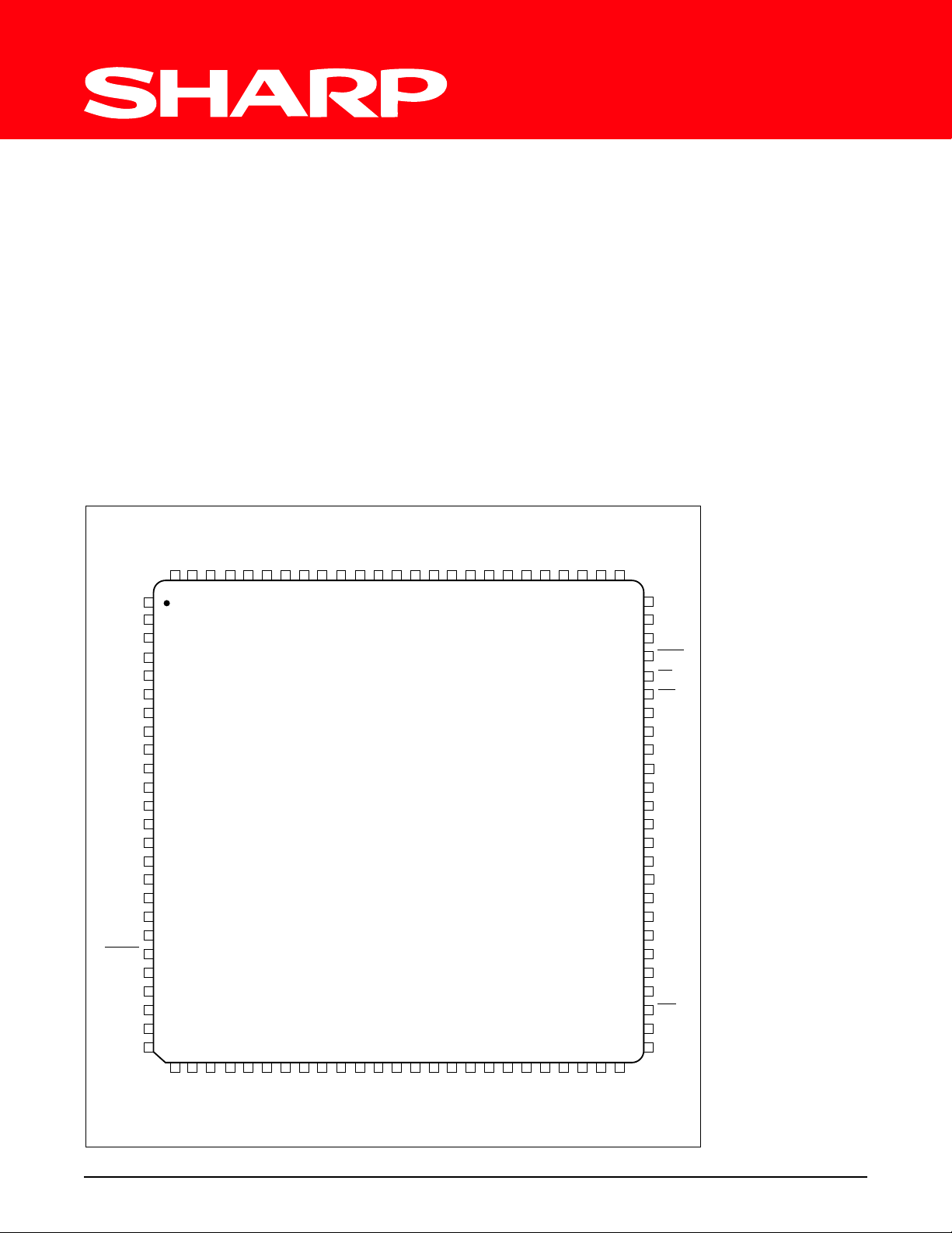
100-PIN LQFP PINOUT
100-PIN QFP
P04
P03
P02
P01
P12
P13
P14
P15
P16
P17
XD0
XD1
XD2
XD3
CP1
CP2
MCLK
BUS8
GND
OSC1
OSC2
RTCVCC
RESET
ADVR
P20
P21
P22
P23
P05
P07
P06
P10
P11
100 99 98 97 96 95 94 93 92 91 90 89 88 87 86 85 84 83 82 81 80 79 78 77 76
1
2
3
4
5
6
7S
8
9
10
11
12
13
14
15
16
17
18
19
20
21
22
23
24
25
26 27 28 29 30 31 32 33 34 35 36 37 38 39 40 41 42 43 44 45 46 47 48 49 50
P00
AD15
AD14
GND
Ω
Ω
AD13
AD12
– Programmable PWM output’s polarity
– Enable/disable PWM
• Supply voltages
– 4.5 V to 5.5 V (main clock at 30 MHz)
– 2.7 V to 5.5 V (main clock at 20 MHz)
• Package 100-pin LQFP (LQFP100-P-1414)
DESCRIPTION
The SM6010 is a 16-bit single-chip microcomputer incorporating
a 16-bit CPU core, LCD controller, watchdog timer, serial interface
(UART, SCI), SIR, PWM output, real time clock, A/D converter
and bus controller.
TOP VIEW
VDD
AD5
AD4
AD11
AD10
AD9
AD8
AD7
AD6
AD3
75
74
73
72
71
70
69
68
67
66
65
64
63 DB9
62 DB8
61
60
59
58
57
56
55
5453DB0
52 CK
51
AD2
AD1
AD0
BYTE
RD
WR
DB15
DB14
DB13
DB12
DB11
DB10
DB7
DB6
DB5
DB4
DB3
DB2
DB1
NMI
P47
X1
P24
P25
P26
P27
AGND
P30
P31
P32
P33
VDD
X2
GND
TEST/VPP
P34
P35
P36
P37
P40
P41
P42
P43
P44
P45
P46
6010-1
SM6010 16-Bit Single-Chip Microcomputers 2
 Loading...