


PRODUCT INFORMATION
SM6004/SM6006
16-Bit Single-Chip
Microcomputers
FEATURES
•ROM capacity:
–61,440 × 8-bits (SM6004)
–126,976 × 8-bits (SM6006)
•RAM capacity:
–2,048 × 8-bits (SM6004)
–3,584 × 8-bits (SM6006)
•External memory expansion function
–On chip bus controller for external memory
–Bus multiplexing/nonmultiplexing selection
–Bus width selection
–Auto wait control
•CPU
–General purpose registers 16-bit × 16
–62 basic instructions (bit manipulation instructions
Suitable for controlling, bit transfer instructions, bit branch
instructions, high speed multiplication and division instructions (16-bits × 16-bits, 16-bits ÷ 16-bits, 32-bits ÷ 16-bits))
•10 addressing modes
–16M of address space
–An interrupt request starts a high performance automatic
data transfer (DTS). Appropriate settings of interrupts and
registers enable hardware automatic data transfer. Various
functions can be operated successively and the resultant data
can also successively be stored.
–System clock cycle 0.133 µs (MIN.)
= 4.5 V to 5.5 V at 30 MHz main clock cycle)
(V
DD
–0.2 µs (MIN.)
= 2.5 V to 5.5 V at 20 MHz main clock cycle)
(V
DD
–Selectable system clocks divided by 2 up to 16 main clocks
for low power operation.
•27 total software interrupts
–24 maskable interrupts (external 4, internal 20)
–3 nonmaskable interrupts
–A nonmaskable interrupt, when used in conjunction with
BST instruction, can trigger the software reset
®
APPLICATIONS:
•
PDA
•
Digital Camera
•Built-in main clock oscillator for system clock
•Standby function: Halt mode/stop mode
•I/O ports × 88/specific purpose function pin × 3
–Input ports × 8 (also serve as A/D input)
–I/O ports × 80 (also serve as function pins)
–Specific purpose function pins × 3 (D/A output pin × 2, bus
mode selection pin × 1)
•Timer
–16-bit multifunction timers × 6
–5-stage capture and 2-stage compare type × 1
–1-stage compare type × 2
–2-stage capture type (or capture and compare) × 2
–2-stage compare, PWM output type × 1
•Watchdog timer (overrun detect timer): 8-bit × 1
•Serial interface
–Selectable universal asynchronous receiver transmitter
(UART)/serial I/O interface (SIO) × 2
–Serial I/O interface (SIO) × 1
•A/D converter
–Resolution 10-bits
–8 channels
–Auto start by triggering with timer output
•D/A converter 8-bit × 2
•High precision PWM outputs
–14-bit × 2
–Bit modulated PWM
•Real time outputs 4-bit × 2
•Supply voltages
–4.5 V to 5.5 V (main clock at 30 MHz)
–2.5 V to 5.5 V (main clock at 20 MHz)
•Packages
–100-pin LQFP (LQFP100-P-1414)
–100-pin QFP (QFP100-P-1420)
Integrated Circuits
Group
DESCRIPTION
The SM6004/SM6006 are single-bit single-chip microcomputers
incorporating a 16-bit CPU core, ROM, RAM, timer unit, watchdog
timer, serial interface (UART, SIO), PWM output, real time output,
A/D converter, D/A converter and bus controller.
The information for this document is from the Microcomputer Databook, issued in March 1997.
Copyright ©1998, Sharp Electronics Corp. All rights reserved. All tradenames are the registered property of their respective owners. Specifications are subject to change without notice. SMT98023
®
PRODUCT INFORMATION
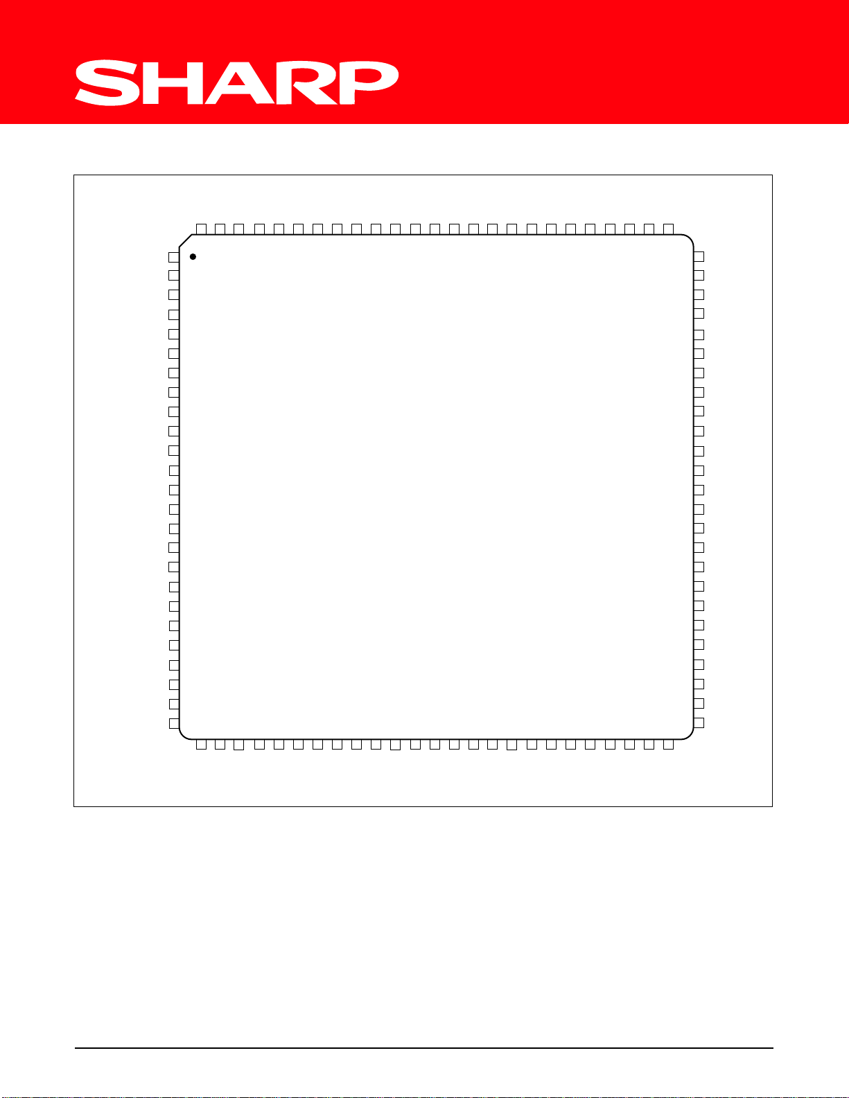
100-PIN LQFP PINOUT
100-PIN LQFP
P3
P3
P3
P4
P4
P4
P4
P4
P4
RESETB
ADVR
P4
P4
P4
P4
P4
P4
P4
P4
P4
P5
P5
P5
P5
11P312
P3
P310P3
8
9
P3
P3
5
6P37
P3
P34P3
3
P32P31P3
0
P214P2
P2
P2
P211P2
P29P2
10
12
13
15
100 99 98 97 96 95 94 93 92 91 90 89 88 87 86 85 84 83 82 81 80 79 78 77 76
1
13
2
14
3
15
4
0
5
1
6
2
7P4
3
8
4
9
5
10
6
11
7
12
8
13
9
14
10
15
11
16
12
17
13
18
14
19
15
20
21
22
0
23
1
24
2
25
3
26 27 28 29 30 31 32 33 34 35 36 37 38 39 40 41 42 43 44 45 46 47 48 49 50
P5
6P57
5P54
P5
AGND
DA
MBUS
1
0
DA
DAVR
TEST
X1
X2
GND
0
P0
P0
1
2
P0
P0
3
P04P0
5
P06P0
8
VDDP27P26P2
9
7
P08P0
5
P010P0
TOP VIEW
75
P2
74
P2
P2
73
P2
72
P2
71
P1
70
P1
69
P1
68
P1
67
66
P1
65
P1
P1
64
63 P1
62 P1
P1
61
60
P1
P1
59
P1
58
P1
57
P1
56
P1
55
5453P0
P0
52 P0
51
P0
11
4
3
2
1
0
15
14
13
12
11
10
9
8
7
6
5
4
3
2
1
0
15
14
13
12
6003-1
SM6004/SM6006 16-Bit Single-Chip Microcomputers 2
 Loading...