

Page 1
SERVICE MANUAL
This document has been published to be used for
after sales service only.
The contents are subject to change without notice.
Refrigerator-freezer
MODEL
SJ-XF50X-T
No.S0311SJF50XTFT
DESTINATION F
CONTENTS
Refer to "REFRIGERATING-CYCLE REPAIR MANUAL" for handling this refrigerant.
Refrigerant; R600a
[1] PRODUCT SPECIFICATIONS
1. SPECIFICATIONS ………………………… 2
2. ACCESSORIES …………………………… 2
3. AUTOMATIC ICE MAKING ……………… 3
[2] DESIGNATION OF VARIOUS PARTS
1. PART NAMES ……………………………… 4
2. INTERNAL STRUCTURE ………………… 5
3. FLOW OF COOL AIR ……………………… 6
4. TEMPERATURE DISTRIBUTION ………… 7
[3] DIMENSIONS
1.
OUTER DIMENSIONS AND CLEARANCE
…8
2. INNER DIMENSIONS ……………………… 9
[4] ELECTRICAL CIRCUIT DIAGRAMS …………10
1. WIRING DIAGRAM …………………………10
2. ELECTRIC ACCESSORIES LAYOUT …… 11
3.
PRECAUTIONS FOR USING LEAD-FREE SOLDER
……12
[5] ELECTRICAL SYSTEM SPECIFICATIONS …13
1. FUNCTIONAL PART SPECIFICATIONS …13
2. MODE FOR DISPLAY ………………………14
[6]
REFRIGERATION CYCLE SYSTEM SPECIFICATIONS
1. R600A PRECAUTIONS ……………………15
2.
TABLE OF R600A CHARACTERISTICS
…15
3. REFRIGERATION CYCLE DIAGRAM …… 15
[7] TROUBLESHOOTING
1. SELF-DIAGNOSIS MODE …………………18
2.
FORCED STOPPING OF DOOR ALARM BUZZER
…2 2
3.
THERMISTOR CIRCUIT CHECK METHOD
…22
4.
INSPECTION FLOWCHART AND REPAIR ITEMS
…2 3
5.
PLASMACLUSTER OK/NG JUDGMENT
…2 5
[8] DISASSEMBLY/ASSEMBLY
1.
GENERAL DISASSEMBLY SEQUENCE
…2 6
2.
REFRIGERATOR COMPARTMENT DISASSEMBLY
…2 7
3. FREEZER COMPARTMENT/ICE
COMPARTMENT DISASSEMBLY ………29
4.
VEGETABLE COMPARTMENT DISASSEMBLY
…3 1
5. HOW TO REMOVE OP. PWB ASS'Y ……32
6. HOW TO REMOVE TERMINAL BOX ……33
7. HOW TO INSTALL R-SUB PACKING ……33
8.
HOW TO INSTALL DUCT RT ASS'Y COVER
…3 4
9.
ADJUSTMENT OF R-DOOR (DOUBLE DOOR)
…3 5
10
. MAIN PARTS ASSEMBLY …………………36
Parts Guide
Page 2
SJXF50XT
2
[1]
PRODUCT SPECIFICATIONS
SPECIFICATIONS1.
Item SJ-XF50X-T
Rated voltage/Rated frequency 110V~60Hz
Rated current (W) 118
Rated power input of heating systems (W) 171
Defrosting input (W) 130
Defrosting heater input (W) 130
O u t e r d i m e n s i o n s
Width×Depth×Height
(mm) 685 x 699 x 1820
Rated total storage volume 501L (17.7 cu.ft.)
Refrigerator compartment 268L (9.47 cu.ft.)
Freezer compartment (upper) 28L (0.99 cu.ft.)
Freezer compartment (lower) 96L (3.39 cu.ft.)
Ice compartment 19L (0.67 cu.ft.)
Vegetable compartment 90L (3.18 cu.ft.)
Weight (kg) 89
Refrigerant (Charging quantity) [Flammable] R600a (68g)
Insulation blowing gas [Flammable] Cyclo pentane (HC)
Cabinet
Inner box material ABS plastic
Outer shell material
PET steel
(Hot dipped zinc plated steel sheet with baked polyester resin coating)
Door
Door shell material Steel
Door inner material ABS plastic
Temperature control Automatic(adjustable)
Defrosting system
Heater system
(automatic start, automatic fi nish)
Refrigerator lamp LED (8 pcs)
Adjustable legs 2
Casters 4
Climate class ST
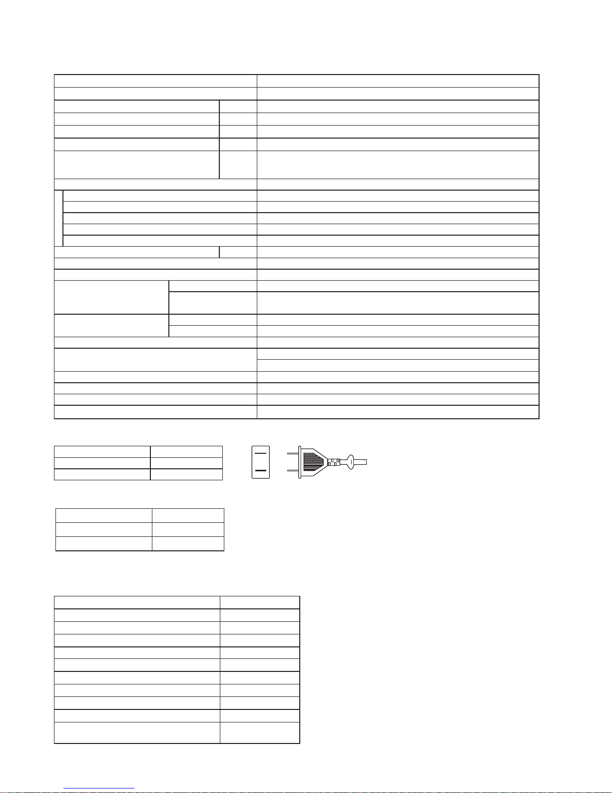
PLUG TYPE
Plug cord 2pin
Plug type A-1
Destination mark F
COLOR
Items -T
Outside color Brown
Inside color White
ACCESSORIES2.
Refrigerator Compartment
R shelf 2
Free set shelf (front/back) 1 each
Chilled case 1
Chilled case tray 1
Case 1
Door pocket (left) 2
Door pocket (right) 2
Egg case 1
Egg tray 1
Bottle pocket (left/right) 1each
Water tank (Tank cap, Lock lever, Slide
cap, Filter case, Water tank, Water fi lter)
1
Page 3
SJXF50XT
3
Freezer compartment (Upper)
Freezer case (Upper) 1
Stainless tray 1
Freezer compartment (Lower)
Freezer case (top) 1
Freezer case (bottom) 1
Ice compartment
Ice storage box 1
Noise-proof sheet 1
Ice scoop 1
Vegetable compartment
Vegetable case 1
Fruit case 1
Pet case 1
Stainless tray 1
Other Accessories and Printed Materials
Foot grille 1
Operation manual 1
Warranty card 1
AUTOMATIC ICE MAKING3.
Water supply method: Storing water in tank/Direct water supply to ice cube maker•
Water tank volume: Approx. 1.0 L•
Ice making capacity (External air temperature: 30ºC, No door opening/closing, Temperature control: “•
中
”, Ice-making mode: “通常”)
Ice cube size Standard Large
Daily Approx. 1.2 kg Approx. 1.5 kg
Once (8 pieces) Approx. 100 g Approx. 230 g
Ice-making time/once•
Ice cube size Standard Large
Ice making
mode
通常
Approx. 2 hours Approx. 3 hours and 30 minutes
明亮
Approx. 6 hours Approx. 8 hours
急速
Approx. 1 hour and 20 minutes Approx. 2 hours
Others: Water filter is attached.•
Ice scoop is provided.
Enables test operation with the cleaning function.
Heat-resistant temperature of water tank: Approx. 60ºC•
Ice storage quantity•
Ice cube size Standard Large
Normal Approx. 4
0
0 to 64 pcs. Approx. 24 to 32 pcs.
Maximum (when leveled) Approx. 88 to 104 pcs. Approx. 40 to 48 pcs.
Page 4
SJXF50XT
4
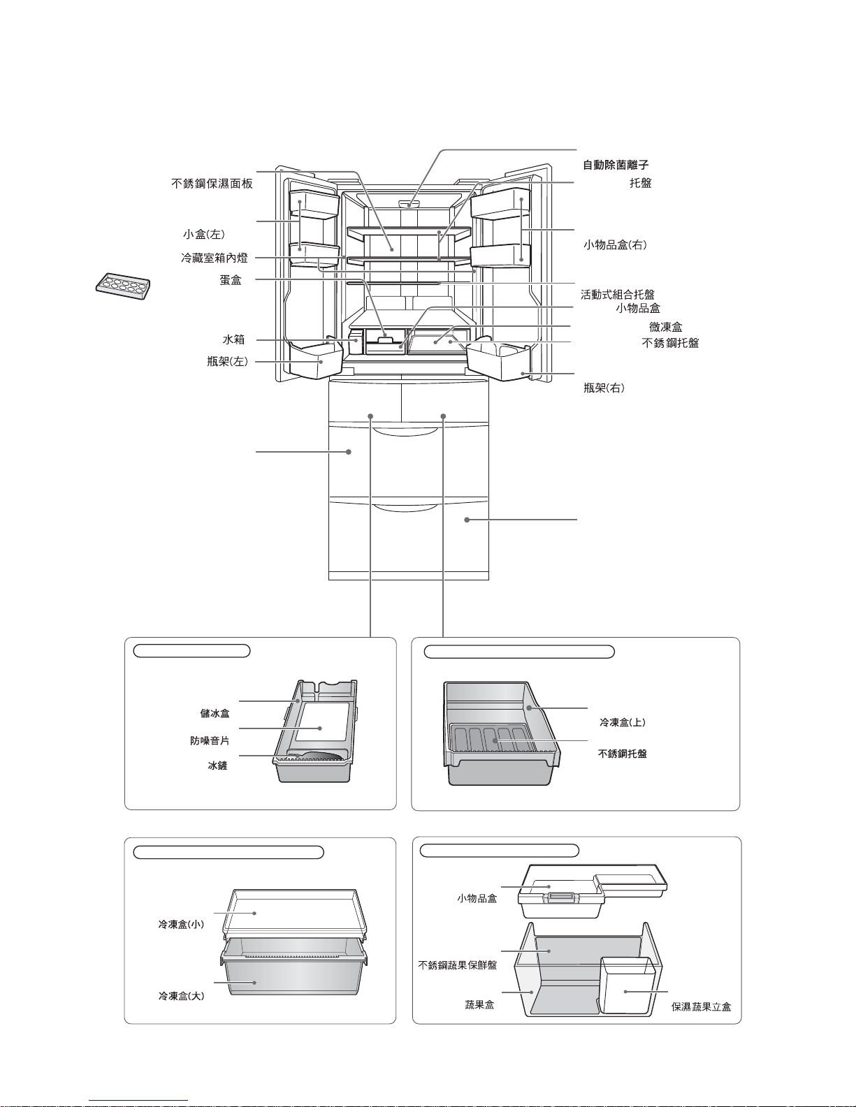
[2] DESIGNATION OF VARIOUS PARTS
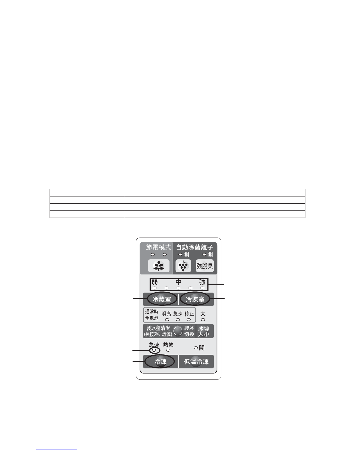
PART NAMES1.
Parts names in parentheses "[ ]" are denominations used in the Operation manual.
>@
Ice compartment
Freezer compartment (upper)
Freezer compartment (lower)
Freezer compartment (lower)
Noise-proof sheet
Ice storage box
Ice scoop
F case sus
F case s
F top case
F bottom case
Vegetable case
Fruit case
V case sus
Pet case
Vegetable compartment
Vegetable compartment
Free set shelf
Egg case
Egg tray
Water tank
Cool plate
Case
Chilled case
C case tray
LED
[ ]
[ ]
[ ]
[ ]
[ ]
[ ]
[ ]
[ ]
[ ]
[ ]
[ ]
[ ]
[ ]
[ ]
[ ]
[ ]
[ ]
[ ]
[ ]
[ ]
Plasmacluster unit
R shelf
Bottle pocket(left)
Bottle pocket(right)
Door pocket(left)
Door pocket(right)
[ ]
[ ]
[ ]
[ ]
Page 5
SJXF50XT
5
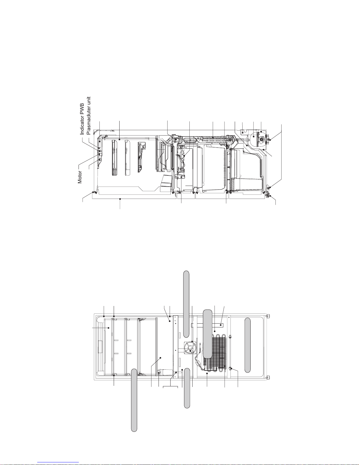
INTERNAL STRUCTURE2.
Catalyzer
Humidity sensor
OP. PWB
Proximity switch
Thermo fuse
Catalyzer
Ice compartment
Freezer compartment (upper)
Vegetable compartment
Refrigerator compartment
R-shower duct ass’y
D-fan motor PCI
Damper ass’y
Thermistor
Ice cube heater
Evaporator
V-thermistor (G-thermistor)
V heater
Damper
Terminal box
(Main PWB, EECON-INV PWB, REACTANCE)
Compressor, protector, valve turret
Fan motor g
Condensor unit
Caster
Evaporating pan
Side view
Adjustable leg ass’y
F proximity switch
Ice maker ass’y
R door switch
LED PWB ass’y
Cool plate
LED PWB ass’y
R-thermistor
Gear pump
Water pipe ass’y
Water pipe heater
Tank heater
F-thermistor
Evaporator
Heater
Front view
Temp.control PWB
Fan motor f
DEF thermistor
Duct heater
Freezer
compartment (lower)
Page 6
SJXF50XT
6
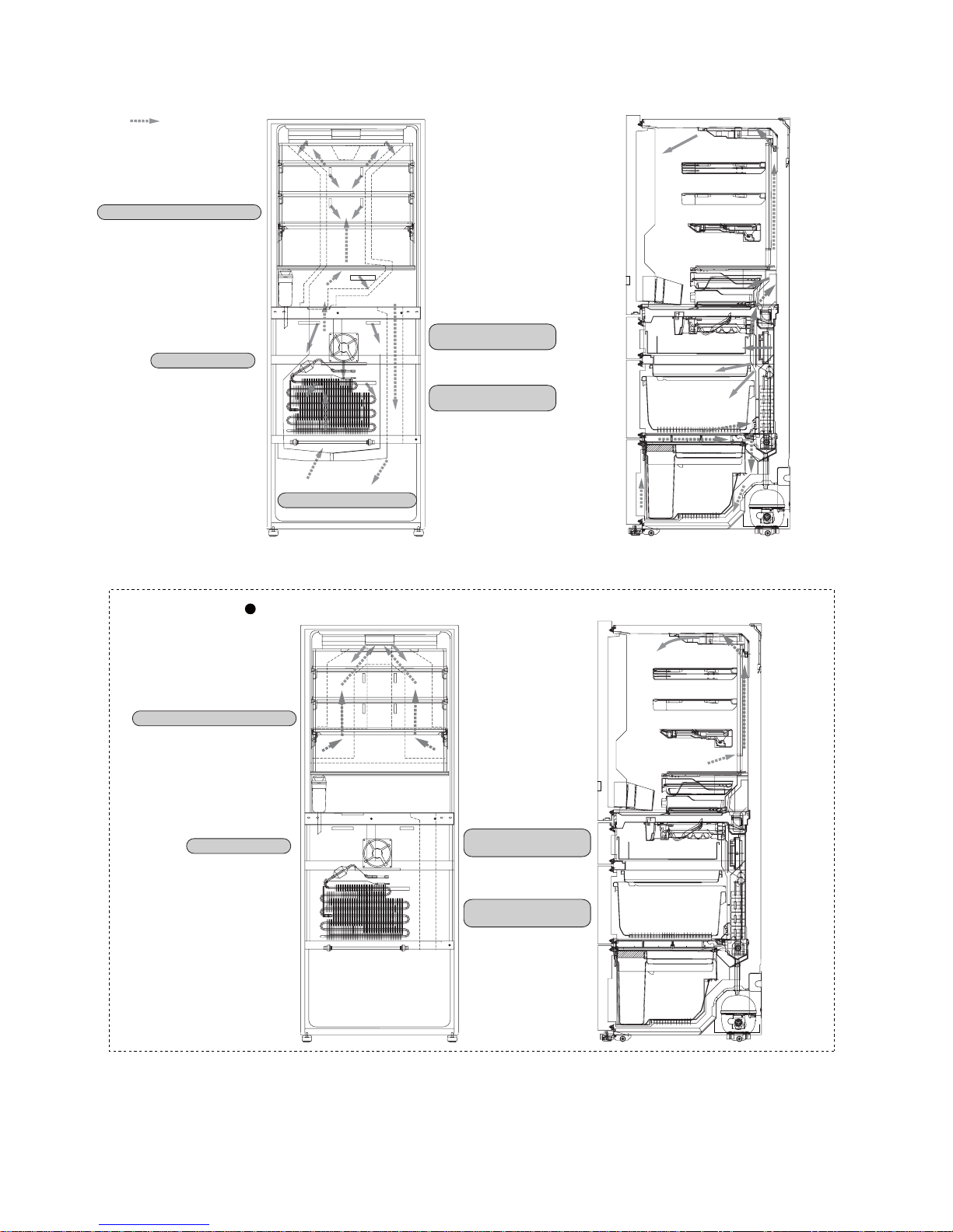
FLOW OF COOL AIR3.
Flow of Cool air
Ice compartment
Refrigerator compartment
Freezer
compartment (lower)
Freezer
compartment (upper)
Vegetable compartment
Side view
Front view
Freezer
compartment (lower)
Freezer
compartment (upper)
Refrigerator compartment
Ice compartment
When Plasmacluster ion is in operation.
Page 7
SJXF50XT
7
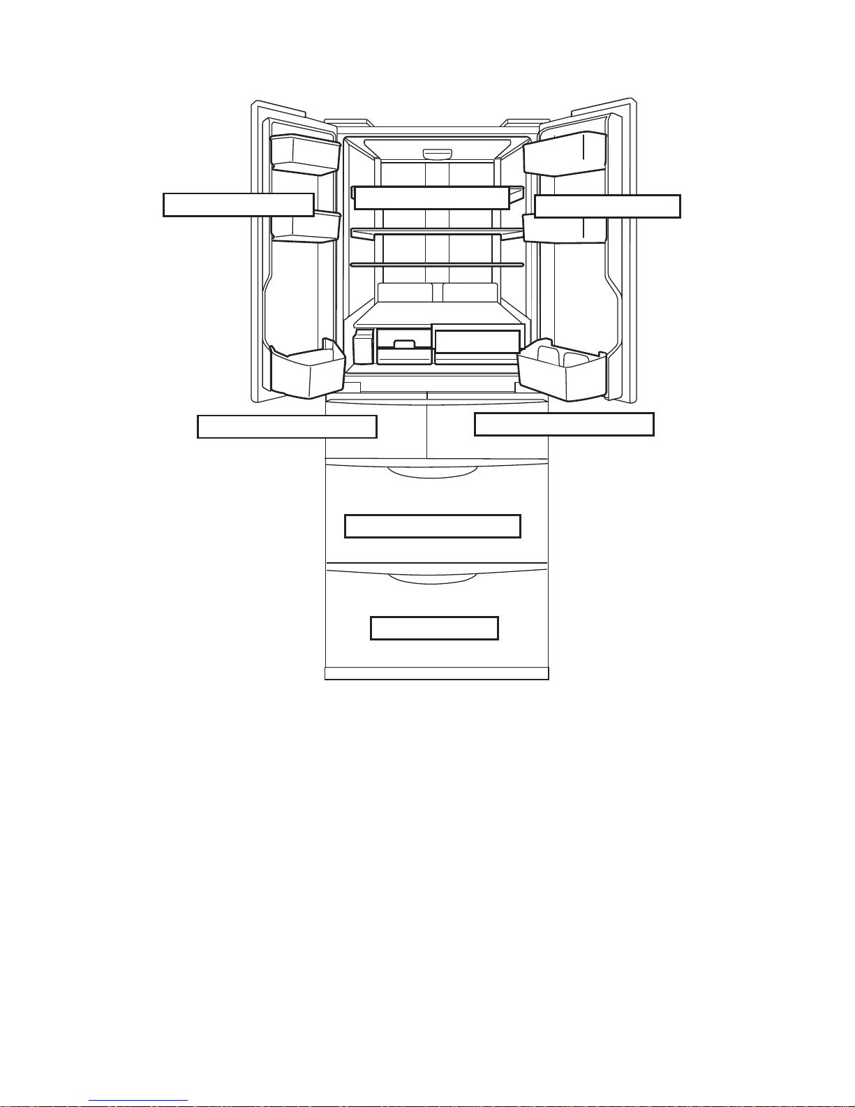
TEMPERATURE DISTRIBUTION4.
●
The temperatures above are indications under the condition of no
food inside, doors closed and surrounding temperature is 30 after
stabilized the inside temperature. (Temperature adjustment is "中")
Approx.3 ~ 7°C
Approx.2 ~ 5°C
Approx.3 ~ 7°C
Approx.0 ~ 2°C
Approx.-17 ~ -19°C
Approx.-18 ~ -20°C
Approx.-18 ~ -20°C
Approx.3 ~ 8°C
Page 8
SJXF50XT
8
[3] DIMENSIONS
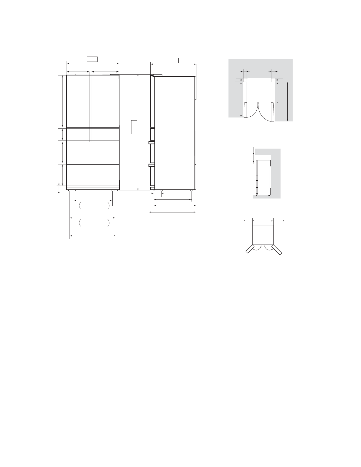
OUTER DIMENSIONS AND CLEARANCE (UNIT:mm)1.
198
281
699
285 396
551
632.5
661.5
608
68
626.5
4
685
1820
853.2180.8
335
365
8
8
15.5
90
50
709
930
1043
705
60 60
Moving wheels
back side
Moving wheels
front side
(Adjustable feet)
More than
More than
More than
135°135°
60
More than
More than
60
Page 9
SJXF50XT
9
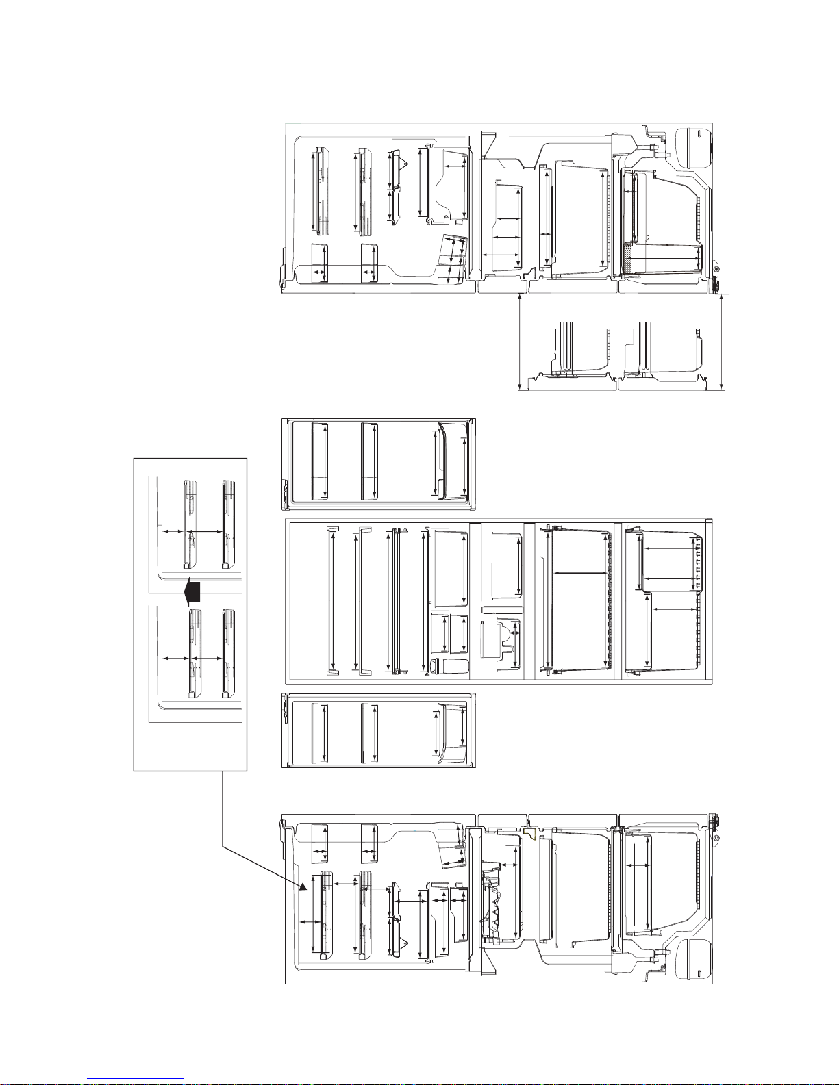
INNER DIMENSIONS2.
The dimensions between shelves can be changed by setting the shelves on the other rails.•
311
292
311
562
292
282
118
156
118
67
95
95
96
246
226
355.5
79.5
70
70
398.8
392
383
235
139
44
112
558
543
542
135
269
269
236
268
144
144
75
75
144
75
144
75
138
123
123
183
135
94
163
398.8
89
81
98
68
311
811651
292
123
138
116
145
22
mm
311
106
354
172
206
211
301
213
238
88
253
310
63
218
519
532
393
94.5
109.5
137.5
172
57
Page 10
SJXF50XT
10
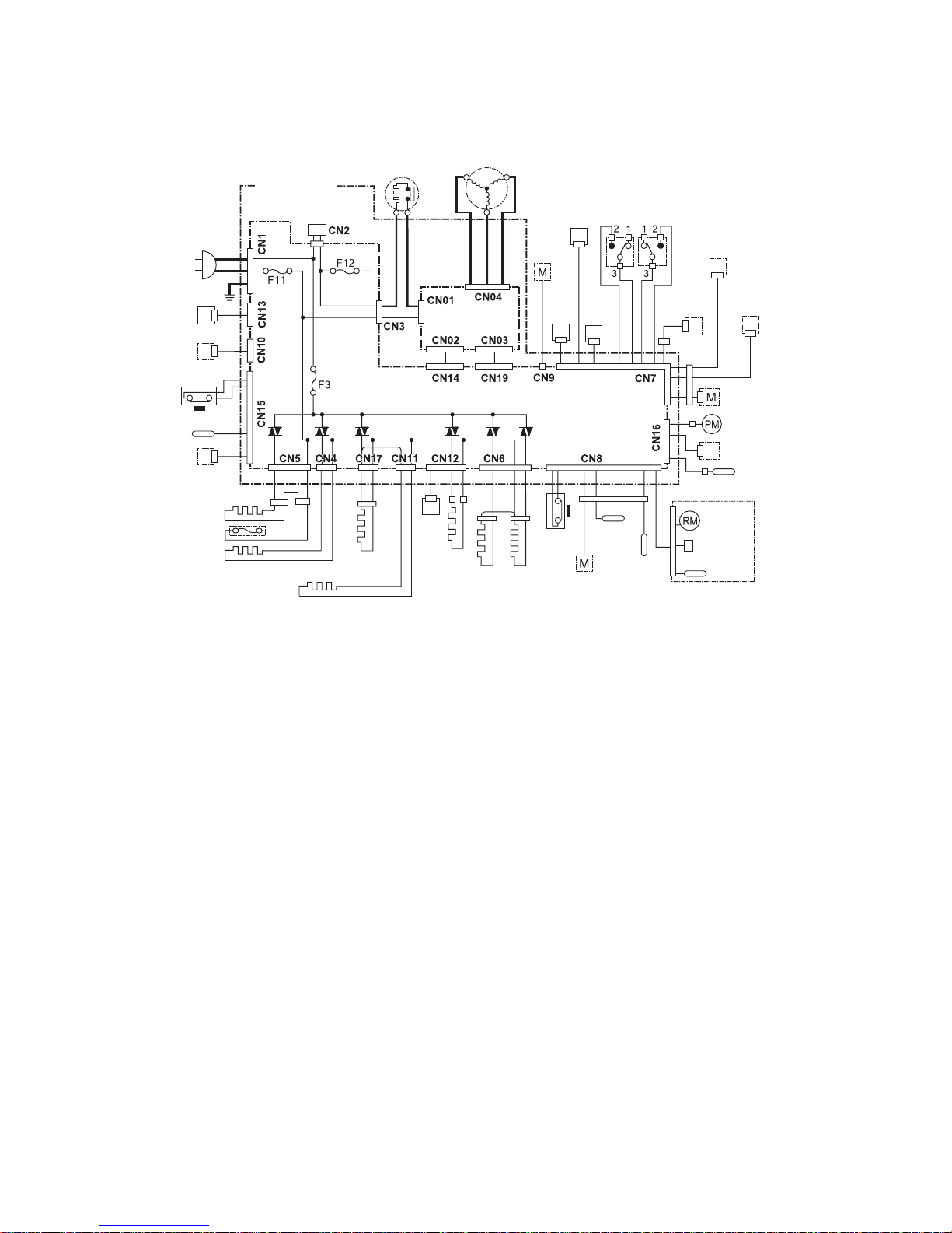
[4] ELECTRICAL CIRCUIT DIAGRAMS
WIRING DIAGRAM1.
Source cord
Reactance
Main PWB
OP
PWB
EECON-INV
PWB
Protector
Compressor
Fan
motor g
Fan
motor f
LED
PWB
(left)
Temp.
control
PWB
Indicator
PWB
Plasmacluster
unit
Motor
D-fan motor PCI
Gear
pump
Damper
R
thermistor
F thermistor
DEF
thermistor
Ice maker unit
Motor
Switch
Thermistor
Proximity
switch
F proximity
switch
Ice cube
heater
R door
heater
V heater
Duct
heater
V thermistor
V damper
Door
switch
(left)
Door
switch
(right)
LED
PWB
(right)
Terminal box
Valve turret
Humidity sensor
Heater
Thermo fuse
Tank heater
Water
pipe
heater
Page 11
SJXF50XT
11
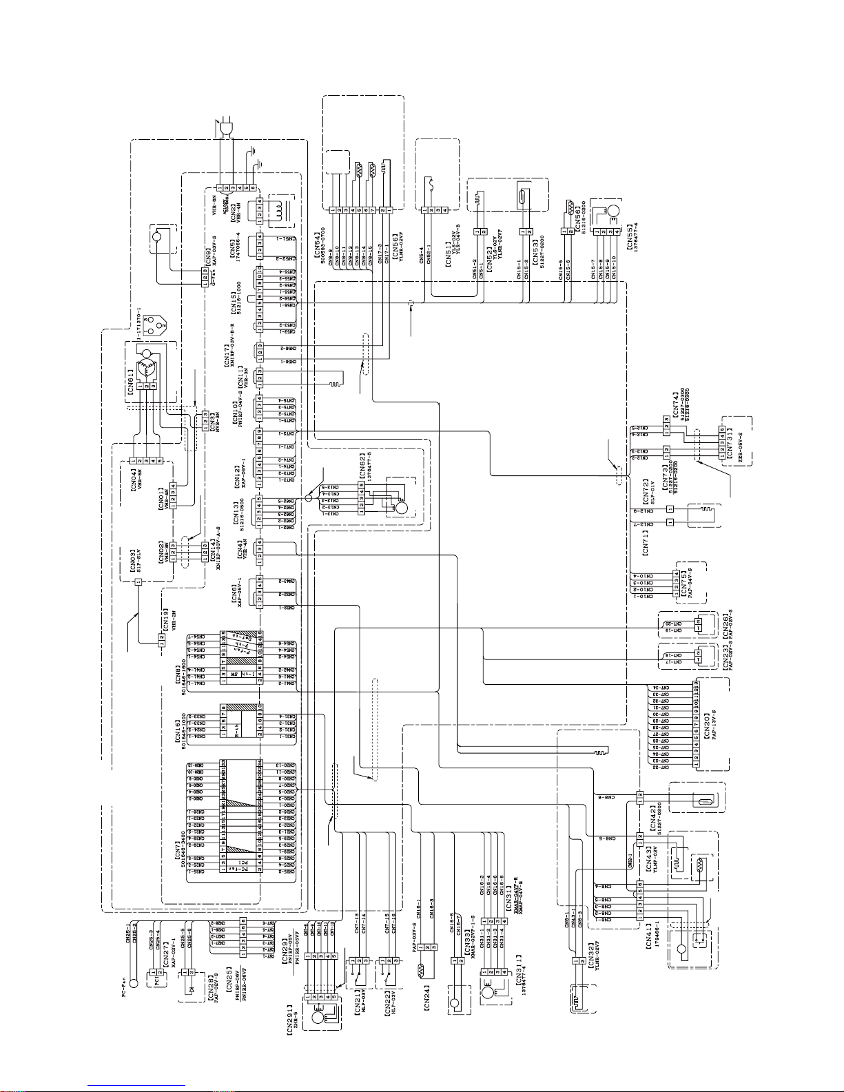
ELECTRIC ACCESSORIES LAYOUT2.
Harness
Harness
Harness
Harness
Harness
Harness
Earth harness
G-fan
Source cord
Black
White
Green
Green
Reactance
Reactance
WhiteWhite
Heater
V thermistor
V damper
YellowBrown
F-proximity
switch
Duct
heater
V-heater
V-heater
Humidity
sensor
R door heater
OP.PWB
Valve turret
Tank heater
Ice cube heater
Water pipe heater
EECON-INV PWB
Green
MAIN PWB
TEMP.CONTROL
PWB
Terminal box
Compressor room
Red
Black
Gray
Yellow
Indicator
PWB
Orange
White
Blue
Motor
Red
Black
Gray
Yellow
Orange
White
Brown
Red
Orange
Yellow
Light green
Blue
Brown
Brown
Black
White
Gray
Red
Red
Orange
Yellow
Light green
Damper harness
Orange
Yellow
Blue
Light green
R door switch
(left)
R door
switch(right)
White
White
Orange
Brown
R thermistor
Red
Red
Yellow
Black
Gear pump
Purple
Purple
Gray
Gray
Blue
Blue
Light green
Light green
R-damper
Brown
White
Orange
Orange
Water pipe
Water pipe
heater
Ice cube tray
Ice cube heater
Brown
Light
green
TEMP. CONTROL PWB
Thermistor
Ice maker unit
Harness
SW
Motor
Red
Brown
Red
Blue
Orange
Light green
Yellow
Yellow
White
White
White
White
White
Light green
Proximity
switch
Black
Black
Red
Orange
Yellow
Light green
Blue
Purple
Gray
White
Black
Brown
Red
Orange
Yellow
Light
green
Blue
Tank heater
LED PWB
(left)
LED PWB
(right)
White
Gray
White
Gray
Humidity
sensor
Brown
Red
Orange
Yellow
R door
heater
White
White
Purple
Blue
OP PWB
Brown Brown
Red
Red
Red
Orange
Orange
Orange
Yellow
Yellow
Yellow
Light
green
V damper
V thermistor
Black
White
Gray
Purple
Blue
Light green
White
Brown
Black
Black
Red
White
White
Gray
Black
Brown
Heater
F proximity
switch
Thermo fuse
Blue
Blue
Orange
Blue
Brown
Yellow
Black
Brown
Fan motor
F thermistor
DEF thermistor
Duct heater
Red
Red
Orange
Yellow
Light green
White
White
White
White
Blue
Blue
Black
Black
Brown
Indicator PWB
LED PWB(right)
LED PWB(left)
R door switch(left)
R door switch(right)
Brown
Brown
Brown
Brown
White
White
White
White
Orange
Orange
Orange
Orange
Orange
Purple
Light green
Light green
Light green
Red
Red
Red
Red
Yellow
Yellow
Yellow
Yellow
Blue
Blue
Blue
Black
Black
Gray
Gray
Gray
Gray
Gear
pump
R
damper
Purple
Light green
Brown
Brown
White
Orange
Orange
Light green
Light green
Red
Yellow
Blue
Red
Red
Black
Yellow
Yellow
Blue
Gray
Proximity switch
Moter
Moter
Inverter DC harness
Yellow
Green
Blue
Black
Blue
Brown
White
Red
Gray
Compressor ass’y
Comp. harness
Compressor
Blue
Protector
Black
Brown
Red
Blue
Gray
Purple
Black
Valve turret
Valve turret
Brown
Orange
Light green
Red
Yellow
Brown
Orange
Light green
White
White
White
White
White
Black
Brown
Brown
Orange
Light green
Light green
Light green
Red
Yellow
Brown
Orange
Brown
Brown
Orange
Red
Red
Yellow
Orange
Red
Yellow
Purple
Page 12

SJXF50XT
12
PRECAUTIONS FOR USING LEAD-FREE SOLDER3.
1) Employing lead-free solder
The PWB of this model employs lead-free solder. This is indicated by the "LF" symbol printed on the PWB and in the
service manual. The suffi x letter indicates the alloy type of the solder.
Example:
Indicates lead-free solder of tin, silver and copper
2) Using lead-free wire solder
When repairing a PWB with the "LF" symbol, only lead-free solder should be used. (Using normal tin/lead alloy
solder may result in cold soldered joints and damage to printed patterns.)
As the melting point of lead-free solder is approximately 40°C higher than tin/lead alloy solder, it is recommend that a
dedicated bit is used, and that the iron temperature is adjusted accordingly.
3) Soldering
As the melting point of lead-free solder (Sn-Ag-Cu) is higher and has poorer wettability, (fl ow), to prevent damage
to the land of the PWB, extreme care should be taken not to leave the bit in contact with the PWB for an extended
period of time. Remove the bit as soon as a good fl ow is achieved.The high content of tin in lead free solder will
cause premature corrosion of the bit. To reduce wear on the bit, reduce the temperature or turn off the iron when it is
not required.
Leaving different types of solder on the bit will cause contamination of the different alloys, which will alter their
characteristics, making good soldering more diffi cult. It will be necessary to clean and replace bits more often when
using lead-free solder. To reduce bit wear, care should be taken to clean the bit thoroughly after each use.
Page 13
SJXF50XT
13
[5] ELECTRICAL SYSTEM SPECIFICATIONS
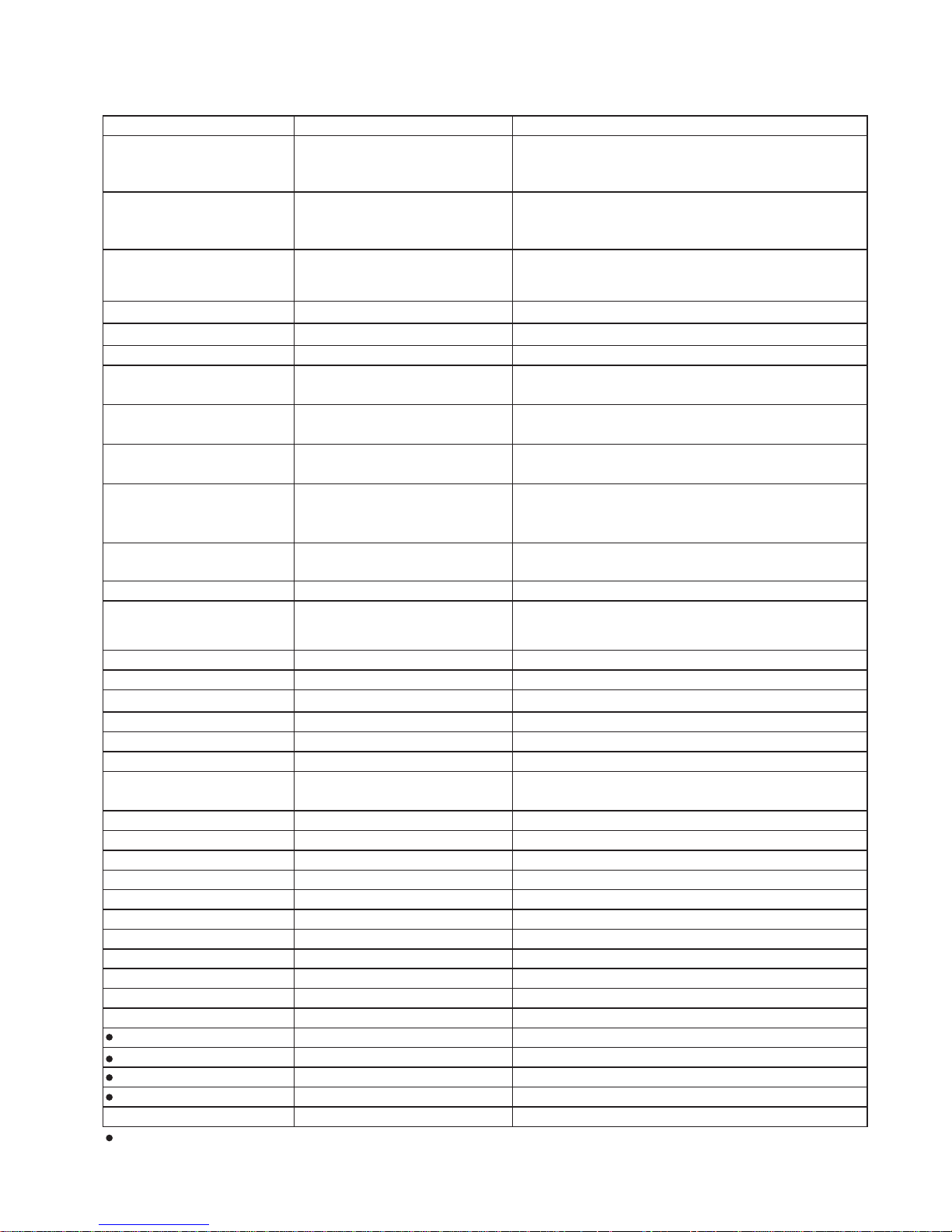
FUNCTIONAL PART SPECIFICATIONS1.
Part Name Specifi cations Function
Fan motor F
Model No.: 4715JL-09W-S37
Rating: DC15V
Power Input: 1.05W (Vs:2.6V)
For cooling
(For freezer compartment)
Fan motor g
Model No.: 4515JL-09W-S10-G01
Rating: DC12V
Power Input: 1.2W
For condensing
(Out side refrigerator)
D-fan motor PCI
Model No.: D09F-12SM20(EX)
Rating: DC12V 0.13A
Power Input: 1.56W
For ion releasing
(For refrigerator compartment)
Damper ass'y (R damper) 415 ± 50Ω (25°C) For refrigerator compartment temperature control
Damper (V damper) 415 ± 50Ω (25°C) For vegetable compartment temperature control
Motor Rating: DC12V 0.13A 300Ω Deodorant/bacteria elimination switching damper
Door switch 5mA 5V DC
For detection of opening or closing of the door
(For refrigerator compartment)
Proximity switch DC15V 100mA 1W
For detection of opening or closing of the door
(For Ice compartment)
F proximity switch DC15V 100mA 1W
For detection of opening or closing of the door
(For freezer compartment (bottom))
Compressor
Model No.: VESD9C+
Rating: 100V 50/60Hz
Resistance value: 9.6Ω (at 25°C)
Protector
MODEL: MSP59AMN-6
Operating temperature: 120°C
For compressor overload prevention
Main PWB For main control
OP.PWB
3.3V 4mA 12mW (Green)
2.3V 10mA 22mW (Red)
3.3V 5mA 16mW (Blue)
For operation panel control (door panel)
LED PWB 15V 72mA x 1.125W For refrigerator compartment illumination
Indicator PWB 3.2V 20mA 38mW For display of Plasmacluster operation
Source cord 125V 7A Source cord (2 Pin + earth)
F thermistor Resistance: 6.4kΩ (at 0°C) For detection of the freezer compartment temperature
R thermistor Resistance: 6.4kΩ (at 0°C) For detection of the refrigerator compartment temperature
DEF thermistor Resistance: 15kΩ (at 0°C) Senses when defrosting is completed
Thermo fuse
Rating: 250 V 10 A
Rated operating temperature: 77°C
For defrosting temperature excessive rise prevention
Thermistor Resistance value: 6.0kΩ (at 0°C) For detection of ice tray temperature
G-thermistor (V-thermistor) Resistance: 1.94Ω (at 0°C) For detection of vegetable compartment temperature
Gear pump Supplies water to the ice cube maker
Heater 110V 130W 93Ω For defrosting
Plasmacluter unit DC12V 20mA For bacteria elimination in compartment
Reactance 9mH±10% Class E wiring
Temp. control PWB For operation panel control (inside)
EECON-INV PWB 100V 50/60Hz For compressor drive
Duct heater 6.0W 1666Ω±7% For prevension of frosting
Humidity sensor 0.5mA DC5V For detection of outside temperature and humidity
Ice cube heater 12W 833Ω For making clear ice cube
Partition heater(R door heater) 3.4W/2910Ω For refrigerator compartment door condensation prevention
Water pipe heater 2.8W/3565Ω For water pipe freezing prevention
Tank heater 1.0W/9638Ω Avoid the water tank from freezing
V heater ass'y 9.0W/1110Ω For vegetable compartment temperature compensation
Valve turret For switching refrigerant
:Unexchengeable parts or Independently unexchangeable parts.
Page 14

SJXF50XT
14
MODE FOR DISPLAY2.
How to set the product in this mode2-1.
Open the doors of the refrigerator compartment and the ice compartment within 2 minutes after turning ON the •
power to the main unit, and press and hold the [
冷凍
] button for 5 seconds or longer.
How to cancel this mode2-2.
With the doors of the refrigerator compartment and the ice compartment opened, press and hold the [•
冷凍
]
button for 5 seconds or longer.
Even if the main power supply is turned OFF, the display mode will be maintained. (not be cancelled)
Operation in the display mode2-3.
Each load (compressor, each fan motor, all heaters, damper, ice release motor, water pump motor) stops.1)
The damper is normally kept opened.2)
Even if the ice compartment or the freezer compartment (lower) door is opened, the door-open buzzer does 3)
not sound.
When the refrigerator compartment door is opened:4)
The refrigerator compartment illumination lamp and indicator LED are lit.•
The cooling/refrigerator compartment PCI fan motor operates.•
The door-open buzzer does not sound.•
Operation panel5)
<Inside of compartment>
The temperature control lamps (five lamps) will blink in sequence one by one.•
If the operation panel button is operated, ordinary operation is executed until the refrigerator compartment door •
is closed.
Note: For indication only. Each mode operation is not executed.
<Outside of compartment>
The operation panel lamps on the door will blink in sequence one by one.•
Page 15
SJXF50XT
15
[6] REFRIGERATION CYCLE SYSTEM SPECIFICATIONS
R600A PRECAUTIONS1.
• Do not use any refrigerant other than R600a.
• Gas leak testers for HFC-134a, CFC-12, HCFC-22, etc., cannot be used.
• A special tool is used for the R600a cycle.
TABLE OF R600A CHARACTERISTICS2.
Refrigerant saturated vapor pressure table R600a
(Unit) Temperature: °C, Pressure: kgf/cm abs
Temperature
Pressure
-20 -15 -10 -5 0 10 15 20 25 30 35 40 45 505
0.74
1.601.340.91 1.11 1.91 2.25 2.64 3.08 3.58 4.13 4.74 5.42 7.006.17
(Unit)Temperature:°C, Pressure: MPa abs
Temperature
Pressure
-20 -15 -10 -5 0 10 15 20 25 30 35 40 45 505
0.073
0.1570.1310.089 0.109 0.187 0.221 0.259 0.302 0.351 0.405 0.465 0.532 0.6860.605
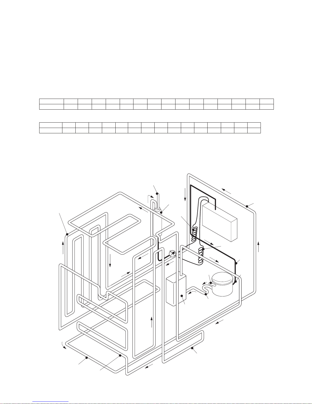
REFRIGERATION CYCLE DIAGRAM3.
Piping Diagram 3-1.
①
②
③
⑤
⑨
⑬
⑭
⑮
⑪
⑧
④
⑯
⑫
⑥
⑩
⑱
⑰
⑦
Charge pipe
←(①~⑱)
Show the order of the refrigerant flow
Back
condenser
Dryer
Capillary
tube A
Evaporator
Capillary
tube B
Suction
connector
Suction
pipe
Charge pipe
Compressor
Discharge pipe
ass’y
Side condenser R
Dew proofing condenser
Bottom condenser
Side condenser L
Extension
barrel
Extra
cond.
unit
ass’y
Page 16
SJXF50XT
16
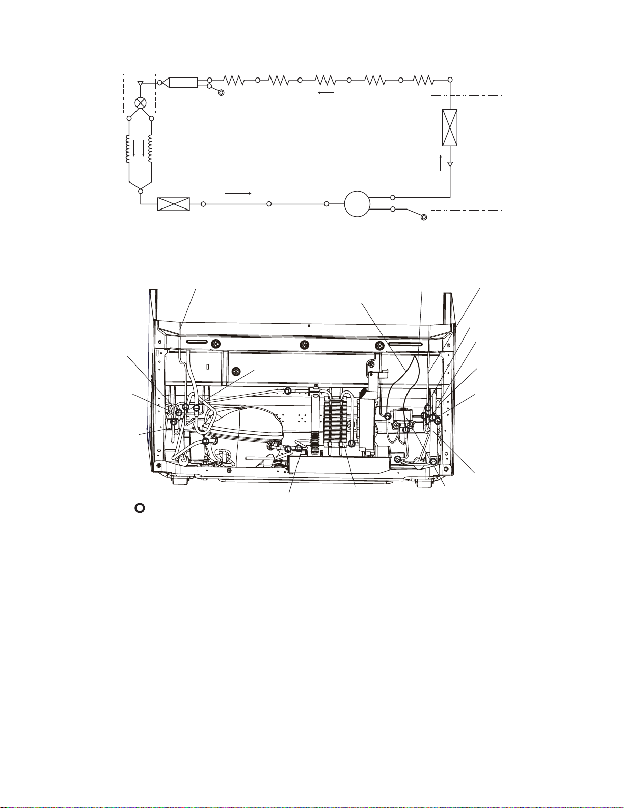
Schematic diagram3-2.
R-valve ass’y
Charge pipe
(Low presure side)
Side condenser L
Side
condenser R
Dryer
Back condenser
Bottom condenser
Charge pipe
(High presure side)
D.P
condenser
Suction connector
Suction pipe
Compressor
Evaporator
Discharge pipe kit
Extra cond. unit kit
Extra cond.
unit
Capillary tube A
I. D.0.55
Capillary tube B
I. D.0.7
Piping detail drawing3-3.
: Pinch point
Compressor
R-valve ass’y
Side condenser R
Inlet
Dew proofing
condenser Inlet
Side condenser R Outlet
Back condenser ass’y Outlet
Bottom condenser ass’y Outlet
Bottom condenser ass’y Inlet
Capillary tube B
Capillary tube A
Back condenser Inlet
Extra cond.unit
ass’y
Dryer
Dew proofing
condenser Outlet
Side condenser L Outlet
Side condenser L Inlet
Discharge pipe
ass’y
Page 17
SJXF50XT
17
Specifi cations of Refrigerant Valve Operation3-4.
Modes and operating conditions of refrigerant valve (3-way valve)1)
Valve is fully closed:1.
• This mode is used in compressor OFF status.
Only fine capillary is opened:2.
• During normal cooling operation
Only wide capillary is opened:3.
• During cooling operation under large load
Both capillaries are opened4.
• The refrigerator is set in this mode for only one minute after the power supply is turned ON. This mode is used
for vacuuming. During cooling operation, this mode is not used.
• Differentiation between fi ne capillary and wide capillary
- Fine capillary: Capillary tube A
- Wide capillary: Capillary tube B
- The fi ne capillary is identifi ed with a yellow mark.
Fault and status of refrigerant valve2)
• There is no method to give an instruction from the PWB and confi rm the valve position.
Refrigerant valve status Problem
1
Both capillaries are opened, and the valve does not operate.
No problem on cooling operation
No problem
2
Only the fi ne capillary is opened, and the valve does not operate.
Cooling performance deteriorates under large load.
Refrigerant shortage may occur, causing frost around
the evaporator inlet to increase.
3
Only the wide capillary is opened, and the valve does not operate.
No problem on cooling operation
No problem
4
Both capillaries are closed, and the valve does not operate.
Cooling operation is disabled.
Cooling operation is disabled even when the
compressor is ON.
• Fault of the refrigerant valve cannot be displayed in the self-diagnosis mode.
Page 18
SJXF50XT
18
[7] TROUBLESHOOTING
SELF-DIAGNOSIS MODE1.
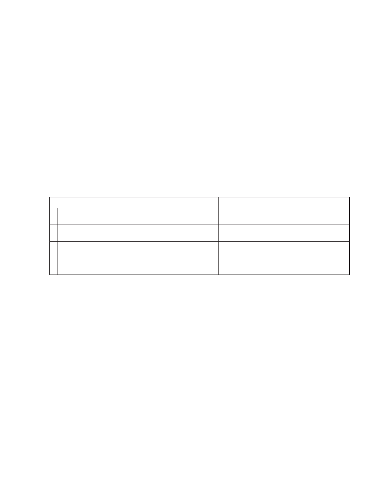
Outline1-1.
The self-diagnosis mode stores fault data for 5 days in the past (including “today”), and displays them by the date •
in the order of occurrence.
Self-diagnosis data to be displayed
Storage of self-diagnosis result
Current fault Fault history
All faults that have currently occurred
(Displayed in the order of fault number)
Faults that occurred in the past fi ve days
(Displayed by the date in the order of occurrence)
Storage of fault data for the past fi ve days
(Up to 9 items per day)
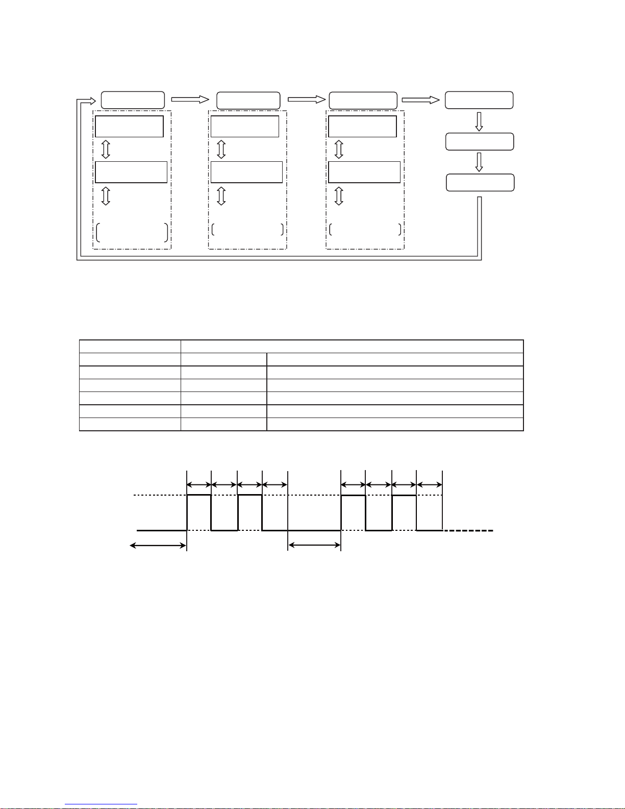
Self-diagnosis display•
Mode input
“Current”
fault display
“Today” fault
history display
“1-day before”
fault history display
“2-days before”
fault history display
“3-days before”
fault history display
“4-days before”
fault history display
Button
operation
Button
operation
Button
operation
Button
operation
Button
operation
Display priority is given to the upper stages
of self-diagnosis display (Table 1) (All items)
The last fault on that day is displayed first, and the older ones
are displayed in the order of occurrence. (Up to 9 items per day)
(Note 1) Self-diagnosis result data for 5 days (including “today”) are stored. 24 hours from the time when the
refrigerator power supply turned ON is defi ned as “one day”.
24 hours 24 hours 24 hours 24 hours 24 hours 24 hours
Today
Current time
1-day before 2-days before
Stored data
3-days before 4-days before
n-days before
Refrigerator power supply
is turned ON
(Note 2) How to clear stored data
After turning ON the power to the main unit, open the doors of the refrigerator compartment and the ice 1)
compartment within 2 minutes, and press and hold the [
冷凍
] button for 5 seconds or longer.
With the doors of the refrigerator compartment and the ice compartment opened, press and hold the [2)
冷凍
]
button for 5 seconds or longer again.
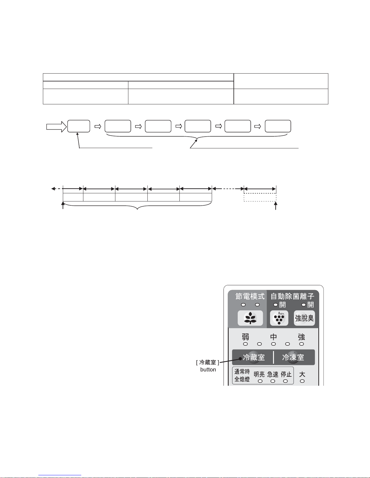
Self-diagnosis mode1-2.
Mode input method1)
With the refrigerator compartment door opened 1)
(the temperature control lamp unlit), press and hold the
[
冷蔵室
] button for 5 seconds.
(The buzzer sounds, “beep, beep”.)
Open and close the refrigerator compartment door three 2)
times.
(within 10 seconds after keeping the [
冷蔵室
] button
pressed for 5 seconds)
The buzzer sounds “beep”, and the refrigerator enters the 3)
self-diagnosis mode.
* The self-diagnosis mode will be automatically canceled
when the status with no button operation continues for 3 minutes.
* If the refrigerator does not enter the self-diagnosis mode, a fault with the door switch system can be considered.
Page 19
SJXF50XT
19
Operation in the self-diagnosis mode2)
The compressor is forcedly turned ON. (Excepting a period of defrosting operation and compressor ON delay •
time)
The cooling, condenser and R-fan motors are forcedly turned ON.•
(These motors will be forcedly turned ON even while the compressor is OFF. However, when the door is opened,
the motors other than the condenser fan motor are kept OFF.)
The refrigerator compartment/vegetable compartment PCI fan and the PCI are forcedly turned ON. (However, •
when the door is opened, the PCI and fan are kept OFF.)
When the refrigerator compartment door is opened, the R damper is forcedly closed. When the refrigerator •
compartment door is closed, the R damper is forcedly opened. (Opening/closing the refrigerator compartment
door activates the R damper operation.)
During execution of the self-diagnosis mode, and for 20 minutes after cancellation of this mode, self-diagnosis •
data serial output is executed.
During execution of the self-diagnosis mode, and for 20 minutes after cancellation of this mode, the door-open •
buzzer does not sound.
Operation during self-diagnosis mode, and self-diagnosis display3)
Self-diagnosis data is displayed on the temperature control panel. (Refer to self-diagnosis display [Table 1].)1)
Self-diagnosis display can be switched by operating the temperature control panel buttons.2)
Temperature control panel button Operation
[
冷凍室
] Fault data forward scroll
[
冷蔵室
] Fault data reverse scroll
[冷凍] Fault occurrence date forward scroll
To return to the previous
display (Reverse scroll)
To proceed to the next display.
(Forward scroll)
Self-diagnosis (fault) display
To change fault occurrence
date to be displayed.
To indicate occurrence date
of displayed fault.
Page 20
SJXF50XT
20
<Example of button operations and self-diagnosis display>
* During self-diagnosis mode input, the “current” fault is displayed.
・
・
・
・
・
・
・
・
・
[During mode input]
“Current” fault
Display of the fault
at the top of Table 1
Press [冷蔵室].
Press [冷凍室].
Press [冷蔵室].
Press [冷凍室].
Display of the fault at
the second top of Table 1
Display of all faults
that have occurred
Press
[冷凍].
Press
[冷凍].
Press
[冷凍].
“Current” fault history
Press
[冷凍].
Press
[冷凍].
Press
[冷凍].
Display of the
latest fault
Display of the
second latest fault
Press [冷蔵室].
Press [冷凍室].
Press [冷蔵室].
Press [冷凍室].
Press [冷蔵室].
Press [冷凍室].
Press [冷蔵室].
Press [冷凍室].
Display of up to 9 items Display of up to 9 items
“1-day before”
fault history
“2-day before”
fault history
Display of the
last fault
Display of the fault just
before the last
“3-days before”
fault history
“4-days before”
fault history
* During forward/reverse scroll of fault display with [
冷凍室
]/[
冷蔵室
] button, if fault data to be displayed next
does not exist, the buzzer sounds “beep-beep”, and the display will not change.
* To display a fault occurrence date for currently displayed data, press the [
冷凍
] lamp.
Fault occurrence date [
冷凍
] lamp.
Current Unlit OFF
Toda y Li t O N
1-day before Blink once. Repeat "2-sec. OFF"/"0.5 -sec. ON/0.5-sec. OFF".
2-days before Blink twice. Repeat "2-sec. OFF"/"0.5-sec. ON/0.5-sec. OFF" twice.
3-days before Blink three times. Repeat "2-sec. OFF"/"0.5 -sec. ON/0.5-sec. OFF" three times.
4-days before Blink four times. Repeat "2-sec. OFF"/"0.5-sec. ON/0.5-sec. OFF" four times.
Example of lamp indication: “2-days before”
0.5-sec. 0.5-sec. 0.5-sec. 0.5-sec. 0.5-sec. 0.5-sec. 0.5-sec. 0.5-sec.
2-sec. pause 2-sec. pause
Repeat
ON
OFF
Page 21
SJXF50XT
21
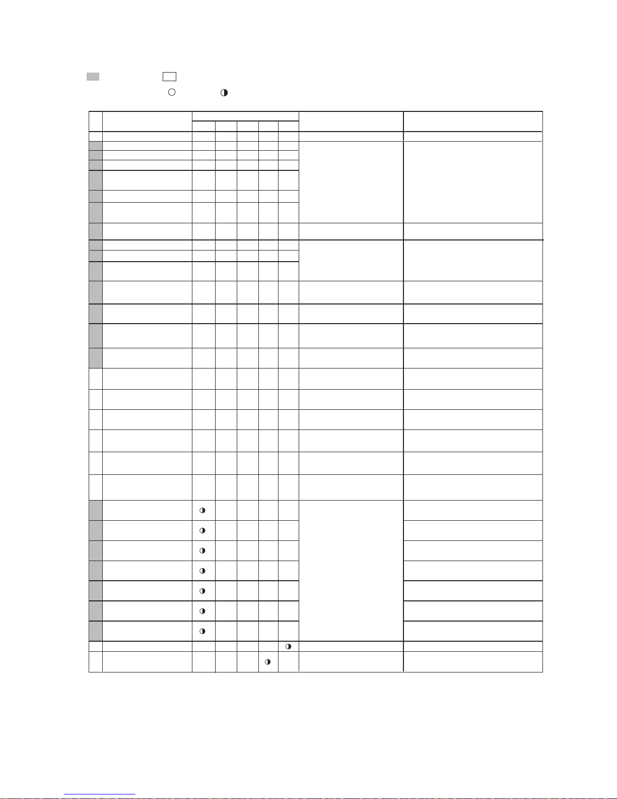
Self-diagnosis display [Table 1] 1-3.
(Problems and problem history related to thermistors, auto ice cube maker, inverter,etc.)
- ○○○○○--
1
○
2
○
3
○○
5
6
○
○○
○
7
○○○
8
○
9
○○
10
○○
12
○○
14
○○○
15
○○○○
16
○
18 ○○
19
○○○
-
20
○○
-
21
○○○
-
22
○○○
-
23
○○○○
-
24
○○
-
25
○
26
○
27
○○
28
○
29
○○
30
○○
31
○○○
32
-
33
-
Status
No.
ExplanationofStatuses
F-thermistor system problem
R-thermistor system problem
V-thermistor system problem
Def-thermistor system problem
External air temperature
thermistor system problem *
There were two defrosted periods (defrosting
heater on time) that lasted for 120 min.
indicates a problem, indicates the status.
Fan motor g system problem
Ice cube maker problems, wiring,
main pwb problems
Without trouble
Thermistor problems, thermistor
wiring short circuit and open
circuit, main pwb problems
Sensorproblems, sensor wiring
short circuit and open circuit,
main pwb problems
A thermistor input value was short circuit
or open circuit.
A thermistor input value was short circuit
or open circuit.
Thermo. fuse or defrosting heater,
open circuit, main pwb problems
Ice cube maker thermistor
system problem
Defrosting problem
Fan motor f system problem
Fan motor problems, fan lock,
wiring, main pwb problems
Description
Ice cube maker
forward operation error
The ice making position detection switch
was produced abnormal signal
at the time
forward operation.
of ice cube maker
Compressor revolution speed
abnormally low
Water tank out of water
The
Water tank
was out of water.
(Detection with thermistor)
Ice storage box full
The Ice storage box was full of ice cubes.
Lamp indication: Lit =
, Blinking = (0.5-sec. ON/0.5-sec. OFF)
Buzzer: Only when a fault is indicated in the current fault display, the buzzer continuously sounds (0.2-sec. ON/1.8-sec. OFF).
Lamp indication (Temperature control LED)
強
弱中
Refrigerator compartment
PCI fan motor fault
Humidity sensor fault
Refrigerator compartment
PCI power supply fault
Power supply clock fault
Ice cube maker
thermistor high temperature
F-thermistor high temperature
R-thermistor high temperature
R-thermistor low temperature
External air temperature
information
Door open information
Inverter wiring error
Inverter overload protection
Inverter startup fault
Inverter overcurrent
Inverter PWB communication
error
Inverter position detection fault
PCI fault, Wiring disconnection
Main PWB fault
Main PWB fault
Compressor fault
Inverter PWB fault
Protector fault, Wiring fault
Main PWB fault
Detection of abnormal current value during
fan motor ON status
Detection of abnormal current value during
plasmacluster ON status
Detection of power supply clock signal
error in main PWB
Thermistor temperature is “-6ºC or higher”
continuously for 6 hours or longer.
F-thermistor temperature is “0ºC or higher”
continuously for 6 hours or longer.
R-thermistor temperature is “+10ºC or higher”
continuously for 6 hours or longer.
R-thermistor temperature is “lower than damper
closing temperature 5ºC” continuously for 2 hours
or longer.
External air temperature is “40ºC or higher”
continuously three times at external air
temperature data update timing.
Door open status has continued for 15 minutes
or longer, or door opening frequency is 200 times
or more/day.
The inverter microprocessor detected
a compressor wiring error.
The inverter microprocessor detected
compressor overload status.
The inverter microprocessor detected abnormal
drop of compressor rotation speed.
The inverter microprocessor detected
a compressor startup fault.
The inverter microprocessor detected overcurrent
in the compressor drive circuit.
Communication error between main
microprocessor and inverter microprocessor
The inverter microprocessor detected
a compressor motor position error.
* The external air temperature thermistor is located on the operation PWB.
Page 22
SJXF50XT
22
FORCED STOPPING OF DOOR ALARM BUZZER2.
* Used when the door switch is faulty.
How to stop
While the door-open buzzer sounds, press the [•
冷蔵室
] and [
冷凍室
] buttons simultaneously and hold them for 3
seconds or longer. (The buzzer sounds three times.)
Forced stopping is cancelled automatically 48 hours later.
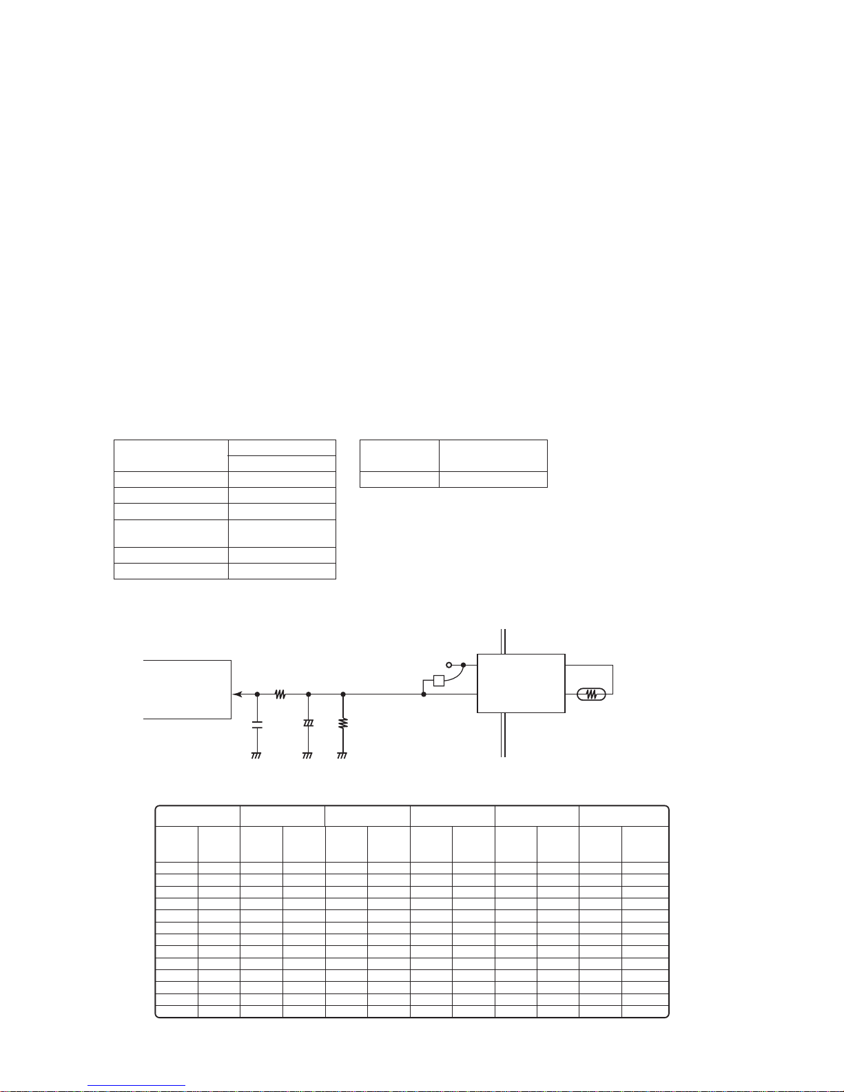
THERMISTOR CIRCUIT CHECK METHOD3.
A thermistor is a semiconductor for which the resistance value changes as the temperature changes.•
This characteristic is used to allow the temperature to be read by a microcomputer.•
(Temperature Resistance value Changed to voltage.)
Check Method1-1.
Disconnect the connectors and measure the thermistor resistances.•
Determination Method1-2.
If the resistance[1] matches, there is a problem with the electronic circuit board.•
If the resistance[1] is different,there is a problem with the harness, connector, or thermistor.•
[ 1 ]
CN8 ⑫
-
⑬
CN8 ⑭
-
⑮
CN16
③-
①
CN10 ④
-
③
CN8 ④
-
⑤
CN10 ②-③
Humidity sensor
Ice cubemaker thermistor
F-thermistor
DEF thermistor
R-thermistor
V-thermistor
External air temperature
thermistor
Resistance Value
*1
(Ω)
pins pins
pins
pins
pins
pins
pins
Voltage Value (V)
*2
CN15 ⑥-⑤
*1. Disconnect connectors and measure the pins on the wiring side(Ω).
Connector
IC1
+
+5V
[1]
Thermistor
Microcomputer
(A/D)
Table of Thermistor Characteristics1-3.
[1]
- 30.0
- 25.0
- 20.0
- 15.0
- 10.0
- 5.0
0.0
5.0
10.0
15.0
20.0
25.0
30.0
35.8
26.1
19.3
14.4
10.9
8.3
6.4
5.0
3.9
3.1
2.5
2.0
1.6
[1]
- 30.0
- 25.0
- 20.0
- 15.0
- 10.0
- 5.0
0.0
5.0
10.0
15.0
20.0
25.0
30.0
35.8
26.1
19.3
14.4
10.9
8.3
6.4
5.0
3.9
3.1
2.5
2.0
1.6
[1]
- 30.0
- 25.0
- 20.0
- 15.0
- 10.0
- 5.0
0.0
5.0
10.0
15.0
20.0
25.0
30.0
83.9
61.2
45.2
33.7
25.5
19.5
15.0
11.7
9.2
7.3
5.8
4.7
3.8
- 30.0
- 25.0
- 20.0
- 15.0
- 10.0
- 5.0
0.0
5.0
10.0
15.0
20.0
25.0
30.0
[1]
F-thermistor
R-thermistor
V-thermistor
DEF thermistor Humidity sensor
Ice cube maker
thermistor
External air
temperature thermistor
Temperature
Resistance
value
Temperature
Resistance
value
Temperature
Resistance
value
Temperature
Resistance
value
Voltage
value
(kΩ)
(°C)
(kΩ)
(°C)
(kΩ)
(°C)
(kΩ)
25.4
19.5
15.1
11.8
9.4
7.5
6.0
4.9
4.0
3.3
2.7
2.2
1.9
[1]
Resistance
value
(kΩ)
(°C) (V)
-
-
-
-
-
-
-
-
0
10
20
30
40
50
60
70
80
90
100
-
-
0.1
0.4
0.7
1.0
1.3
1.5
1.8
2.1
33.1
25.6
20.0
15.8
12.5
10.0
8.1
2.4
2.7
3.0
Temperature
(°C)
- 30.0
- 25.0
- 20.0
- 15.0
- 10.0
- 5.0
0.0
5.0
10.0
15.0
20.0
25.0
30.0
Temperature
(°C)
Page 23

SJXF50XT
23
INSPECTION FLOWCHART AND REPAIR ITEMS4.
During check of the PWB circuits, use thorough caution not to get electric shock.•
To check resistance of electric parts, be sure to disconnect the power supply plug. (Turn OFF the power supply.)•
Problem Self-diagnosis display Check/inspection point Action on error detection
Refrigerator does not
cool at al l
(The compressor
does not wo rk.)
F-ther mistor f ault 1) Con nector i nsert ion che ck (Main P WB, inte rmedia te
connector)
2) Thermi stor res istanc e check (C heck th e value in th e
thermistor characteristic table.)
3) If the above c heck re sults are n ormal:
1) Correct t he inst allatio n.
2) Replace t he ther mistor.
3) Replace t he main PW B.
Invert er wirin g error 1) Inverter PW B – comp ressor w iring c heck (Co nnecto r
inser tion/ wire br eak chec k)
2) If the above c heck re sults are n ormal:
1) Correct t he inst allatio n, or repl ace the wi ring.
2) Replace t he inver ter PWB o r main PWB .
Invert er commu nicati on erro r 1) Inverter P WB – main P WB wiri ng chec k, Protec tor chec k
(Conne ctor ins erti on/w ire brea k check)
2) If the above c heck re sults are n ormal:
1) Correct t he inst allatio n, or repl ace the wi ring/ protect or.
2) Replace t he inver ter PWB o r main PWB .
Invert er overlo ad protec tion 1) Is there any pr oblem ab out the re frige rator hea t radiati on
space?
2) Compre ssor wou nd wire re sistanc e chec k (Refer to pa ge 13)
3) Refrige rant valve o perati on chec k
4) If the above c heck res ults are n ormal:
1) Improve the r efrige rator ins tallat ion con dition .
2) Replace t he comp ressor.
3) Replace t he refr igerant v alve or mai n PWB.
4) Replace t he inver ter PWB or m ain PWB.
Invert er rotati on spee d abnorm al drop
Invert er star tup fault
Inverter overcurrent
Invert er posit ion detec tion fa ult
1) Compres sor wound w ire resi stanc e check (R efer to pag e 13)
2) Refrige rant valve o perati on chec k
3) If the above c heck re sults are n ormal:
1) Replace th e compre ssor.
2) Replace t he refri gerant v alve or main P WB.
3) Replace t he inver ter PWB o r main PWB .
F-ther mistor h igh-t empera ture 1) Connec tor inse rtio n check ( Main PWB , interm ediate
connector)
2) Thermi stor res istanc e check (C heck th e value in th e
thermistor characteristic table.)
3) Compre ssor/f reezin g cycle ch eck
4) If the above c heck res ults are n ormal:
1) Correct t he inst allatio n.
2) Replace t he ther mistor.
3) Replace t he comp ressor /freez ing cycl e.
4) Replace t he inver ter PWB or m ain PWB.
Cooling performance
is in suf fi cient
(The c ompres sor is
working.)
DEF ther mistor f ault
Exter nal air te mperat ure ther mistor f ault
1) Connecto r inser tion c heck (Ma in PWB, i ntermed iate
connector)
2) Thermi stor res istanc e check (C heck th e value in th e
thermistor characteristic table.)
3) If the above c heck re sults are n ormal:
1) Correct t he inst allatio n.
2) Replace t he ther mistor.
3) Replace t he main PW B.
Coolin g fan moto r fault
Conden ser fan mo tor fault
1) Connecto r inser tion c heck (Ma in PWB, i ntermed iate
connector)
2) Fan motor installation/condition/operation check
3) If the above c heck re sults are n ormal:
1) Correct t he inst allatio n.
2) Correc t the inst allati on, or rep lace the f an motor.
3) Replace t he main PW B.
Defros ting faul t 1) Conne ctor inse rtio n check ( Main PW B, inter mediate
connector)
2) Defrost ing heat er resis tance c heck (Che ck the val ue in the
functi onal par t specifi cations.)
3) If the above c heck re sults are n ormal:
1) Correct t he inst allatio n.
2) Replace t he defro sting he ater or tem peratur e fuse.
3) Replace t he main PW B.
Exter nal air te mperat ure infor mation
Door op en infor mation
1) Refriger ator inst allati on/ope rating c onditi on chec k
(Instal lation e nvironm ental te mperat ure, Doo r openin g/clos ing
frequency)
1) Improve the i nstalla tion/o perati ng condi tion.
F-thermistor high temperature
No self- diagnosis faul t
1) F-therm istor co nnecto r inser tion ch eck (Mai n PWB,
intermediate connector)
2) F-ther mistor r esista nce che ck (Chec k the value i n the
thermistor characteristic table.)
3) Coolin g fan motor o perati on chec k (Rotati on spee d is low.)
4) Condens er fan moto r operat ion che ck (Rota tion spe ed is
low.)
5) Compr essor an d freezi ng cycle c heck
6) Door packing inspection and installation/operating conditions
(Instal lation e nvironm ental te mperat ure, door o pening /closi ng
freque ncy, too much s tuffe d food, etc .)
7) If the ab ove check r esults a re norma l:
1) Correct t he inst allatio n.
2) Replace t he ther mistor.
3) Replace t he cool ing fan mot or.
4) Replace t he conde nser fan m otor.
5) Replac e the com presso r/free zing cyc le.
6) Improve th e packin g mounti ng/ins tallat ion/op eratin g
condition.
7) Replac e the inver ter PWB or main PWB .
Freeze r
compar tment is too
much cooled.
F-thermistor fault
1) Connecto r inser tion c heck (Ma in PWB, i ntermed iate
connector)
2) Thermi stor res istanc e check (C heck th e value in th e
thermistor characteristic table.)
3) If the above c heck re sults are n ormal:
1) Correct t he inst allatio n.
2) Replace t he ther mistor.
3) Replace t he main PW B.
Page 24

SJXF50XT
24
Problem Self-diagnosis display Check/inspection point Action on error detection
Refrigerator
compar tment (chilled
case) is not c ooled
well
R-ther mistor f ault 1) Connec tor inse rtion c heck (M ain PWB , interm ediate
connector)
2) Thermi stor res istanc e check (C heck th e value in th e
thermistor characteristic table.)
3) If the above c heck re sults are n ormal:
1) Correct t he inst allatio n.
2) Replace t he ther mistor.
3) Replace t he main PW B.
R-fan mo tor fault 1) Connector ins erti on chec k (Main PW B, inter mediat e
connector)
2) Fan motor installation/condition/operation check
3) If the above c heck re sults are n ormal:
1) Correct t he inst allatio n.
2) Correc t the inst allati on, or rep lace the f an motor.
3) Replace t he main PW B.
R-thermistor high temperature
No self- diagnosis faul t
1) R-dampe r conne ctor inse rtio n check ( Main PW B,
intermediate connector)
2) R-damper installation/condition/operation check
3) R-ther mistor c onnec tor inser tion check (Ma in PWB,
intermediate connector)
4) R-ther mistor re sista nce che ck (Chec k the value i n the
thermistor characteristic table.)
5) R-fan mo tor oper ation ch eck (Rot ation sp eed is low.)
6) Door pac king ins pecti on and installation/operating conditions
(Instal lation e nvironm ental te mperat ure, door o pening /closi ng
freque ncy, too much s tuffe d food, bl ock of co ld air supp ly por t
at the bac k of the chi lled cas e, sucti on por t, etc.)
7) If the ab ove check r esults a re norma l:
1) Correct t he inst allatio n.
2) Correc t the inst allati on, or rep lace the R -damp er.
3) Correc t the inst allati on.
4) Replace t he therm istor.
5) Replac e the R-fa n motor.
6) Improve th e packin g mounti ng/ins tallat ion/op eratin g
condition.
7) Replac e the main P WB.
Refrigerator
compar tment (chilled
case)is to o much
cold.
R-ther mistor f ault 1) Connec tor inse rtion c heck (M ain PWB , interm ediate
connector)
2) Thermi stor res istanc e check (C heck th e value in th e
thermistor characteristic table.)
3) If the above c heck re sults are n ormal:
1) Correct t he inst allatio n.
2) Replace t he ther mistor.
3) Replace t he main PW B.
R-ther mistor l ow tempe rature 1) R-damper c onnec tor inser tion check (Ma in PWB,
intermediate connector)
2) R-damper installation/condition/operation check
3) If the above c heck re sults are n ormal:
1) Correct t he inst allatio n.
2) Correc t the inst allati on, or rep lace the R -damp er.
3) Replace t he main PW B.
Ice mak ing failu re
Ice mak ing spee d is
low
Ice rel ease ope ration e rror 1) Conn ector in sert ion che ck (Main P WB, inte rmedia te
connector)
2) Ice maker ass’y installation/condition/operation check
3) If the above c heck re sults are n ormal:
1) Correct t he inst allatio n.
2) Correc t the inst allati on, or rep lace the i ce maker as s’y.
3) Replace t he main PW B
Ice maker t hermi stor faul t 1) Connecto r inser tion c heck (Ma in PWB, i nterme diate
connector)
2) Thermi stor res istanc e check (C heck th e value in th e
thermistor characteristic table.)
3) If the above c heck re sults are n ormal:
1) Correct t he inst allatio n.
2) Replace t he ther mistor.
3) Replace t he main PW B.
Ice maker t hermi stor hig h tempera ture 1) Con nector i nsert ion che ck (Main P WB, inte rmedi ate
connector)
2) Thermi stor res istanc e check (C heck th e value in th e
thermistor characteristic table.)
3) Door pac king ins pectio n and installation/operating condition
check
4) If the above c heck res ults are n ormal:
1) Correct t he inst allatio n.
2) Replace t he ther mistor.
3) Improve the mounting/installation/operating condition.
4) Replace t he main PW B.
Ice str orage box i s full of ic e cubes 1) Ice sen sor oper ation c heck (Che ck for co ntact w ith the ic e
storage box, etc.)
2) Ice maker a ss y installation/condition/operation check
3) If the above c heck re sults are n ormal:
1) Correct o r replac e the ic e sensor.
2) Correc t the inst allati on, or rep lace the i ce maker as s’y.
3) Replace t he main PW B.
No water in w ater tank 1) Water tank water l evel and ins tallat ion chec k
2) Water pump c onnect or inser tion c heck (Ma in PWB,
intermediate connector)
3) Water pump installation/condition/operation check
4) Water pipe installation/condition check
5) Ice make r therm istor res istanc e chec k (Check th e value in
the ther mistor c harac terist ic table.)
6) If the above c heck re sults are n ormal:
1) Replenish w ater into th e water ta nk. Cor rect the
installation.
2) Correc t the inst allati on.
3) Correc t the inst allati on, or rep lace th e water pump.
4) Correc t the inst allati on.
5) Replac e the ther mistor.
6) Replace t he main PW B.
No self- diagnosis fault 1) Ice maker ass’y and wa ter pump op eratio n check i n ice tray
cleaning operation
2) Water pipe he ater res istanc e check (ap prox. 3.5 k)
3) Water pump/pipe installation/condition/operation check
4) If the above c heck res ults are n ormal:
1) Replace th e ice maker a ss’y or wate r pump.
2) Correc t the co nnecto r install ation, o r replac e the water
pipe heater.
3) Correc t the inst allati on, or rep lace th e water pump /pipe.
4) Replace t he main PW B.
Page 25

SJXF50XT
25
Plasmacluster OK/NG Judgment5.
Judgment procedure1)
Disconnect the power supply, and keep the refrigerator compartment door opened for 5 minutes or longer to raise 1.
the temperature in the refrigerator compartment.
After closing the refrigerator compartment door, connect the power supply, and turn ON the plasmacluster. 2.
(When the plasmacluster is turned ON, the blue LED in the compartment is ON.)
Check the ion at the PCI discharge port with the ion measuring instrument.3.
Refrigerator compartment: Measure PCI while pressing the door switch.
If at least either ion quantity (+ or -) is indicated, the judgment result is acceptable.
This procedure is intended for simplified check of fan motor and plasmacluster operations. Even if the ion •
quantity specified in the catalog cannot be confirmed, it is no problem. *
* Reason why the ion quantity specifi ed in the catalog cannot be confi rmed:
Because the ion quantity specified in the catalog has been measured in stable operating conditions with the •
refrigerator compartment door closed.
If the ion measuring instrument is inserted/removed when the compartment is cooled, condensation occurs with •
the measuring instrument, which disables reliable ion quantity check due to a measuring error.
Measuring position2)
(下)
PCI measuring position
During PCI operation
Refrigerator
compartment
Ice
compartment
Freezer
compartment
(Upper)
Freezer
compartment
(Lower)
Vegetable
compartment
Page 26

SJXF50XT
26
[8] DISASSEMBLY/ASSEMBLY
GENERAL DISASSEMBLY SEQUENCE1.
1-2
1-3
1-5
1-6
1-7
2-1-2
2-2
2-3
2-4
2-5
2-3-2
1-4
1-1
1-2
1-3
1-4
1-5
1-6
1-7
(1)
Refrigerator compartment
Accessories (Shelves・Chilled case・Water tank)
Partition support・C-shelf ass’y
Duct RT ass’y
R-shower duct ass’y
PCI box ass’y
R-C box ass’y・
Connector cover R
Pipe cover
2-1-2
2-1
2-2
2-3
2-4
2-5
2-3-2
(2)
Freezer compartment
Accessories
(Ice storage box・
Freezer cases)
SW cover
Ice maker ass’y T-SK
C-part. FI-B
C-part. FI-FK
(When replacing Proximity switch)
E.V cover ass’y
Heater・DEF thermistor holder
(When replacing F proximity switch)
Page 27

SJXF50XT
27
REFRIGERATOR COMPARTMENT DISASSEMBLY2.
Main component Contained parts
RC box ass'y Gear pump, R-thermistor, damper
Pipe cover -
R-shower duct ass'y Catalyzer
D-PCI box ass'y Plasmacluster unit, indicator PWB, D-fan motor PCI, Motor, O catalyzer
Remove the accessories (shelf, chilled case, etc.).1.
Remove the chilled shelf stopper.2.
Raise the back of the shelf slightly from the bottom,
and pull it to the front.
Chilled shelf stopper
C case cover
How to remove C case cover1)
C-shelf ass’y (back side)
C case cover
(C-shelf ass'y with the C case cover attached)
Unhook three claws at the back and pull out the
protrusions in front.
Claws at the back
: Protrusion
C case cover
Installation is the reverse procedure to removal.•
How to remove chilled lock2)
Unhook two claws (if they are tight and stuck, insert
a thin flathead screwdriver (or a steel scale) to
unlatch them) and open the cover.
Remove one screw.
Claws
Chilled lock
Screw
Remove partition support l and partition stay.3.
Pull it while holding it up slightly.
Partition support l
Partition stay
Remove duct RT rivet, and remove duct RT cover.4.
Pull it downward to raise it. (If it is stuck, insert a
fl athead screwdriver to raise it.)
Duct RT cover
Duct RT rivet
Page 28

SJXF50XT
28
Remove the four locations of the inner protrusion.
When the protrusions are unhooked, pull it downward
to remove it.
: Protrusion
Remove R shower duct ass'y.5.
While holding the top by hand, pull the duct to the
front. (Claws are located at 8 places.)
: claw
R shower duct ass’y
Remove the D-PCI box ass'y.6.
Remove three screws.
P
ull the box downward to release the claws at the
front (at 2 places).
(The claws are directly applied to the food liner.
Use caution not to damage the food liner.)
After the claws are released, pull the box
downward, and release the remaining claws.
Disconnect two connectors.
□ : claw
○
: screw
D-PCI box ass’y
Remove the connector cover R (Screw at 1 place, 7.
Claws at 2 places), and disconnect four connectors.
Connector cover R
□ : claw
○
: screw
Remove the RC box ass'y.8.
Remove two screws, and pull the box to the front
while holding the top by hand.
Disconnect the joint pipe connected to the pipe
cover.
RC box ass’y
Joint pipe
Screw
Screw
CAUTION: Precaution for mounting the RC box ass'y
Make sure that the joint pipe is connected. Check for
twisting and lead wire entanglement.
Remove the damper.9.
Remove R-C box insu A/B from R-C box.1)
R-C box
R-C box insu A
R-C box insu B
Damper
Page 29

SJXF50XT
29
Cut A-Sealer R-C box insu A along the joint of R-C 2)
box insu A/B (dotted line).
R-C box insu A
R-C box insu B
Damper
A-sealer
Remove 3) the damper.
Pull out the pipe cover.10.
□ : claw
Pipe cover
FREEZER COMPARTMENT /ICE COMPARTMENT DISASSEMBLY3.
Main component Contained parts
Ice maker ass'y T-SK Ice maker thermistor, Ice maker ass'y, Ice cube heater, I-grill, Ice sensor, Ice cube maker
C-part. FI-FK Proximity switch
EV cover ass'y F-thermistor, DEF thermistor, Fan motor F, Duct heater
Heater DEF thermistor holder ass'y
(In vicinity of evaporator)
Thermo. fuse ass'y, DEF2 thermistor
Remove the accessories (cases and shelves of 1.
freezer compartment and vegetable compartment).
Remove the SW cover. •
(When replacement of F-LED PWB ass’y)
SW cover
Remove the Ice maker ass'y T-SK.2.
Remove the screw and pull it toward you while 1)
pressing the claw on the front.
Remove connector.2)
Flathead screwdriver etc.
Ice meker ass'y T-S
K
Screw
CAUTION: Precautions for handling the ice maker ass'y T-SK
Securely insert the 4 claws. If the claws are not •
inserted completely and they come loose,the ice
maker ass'y T-SK could fall down during ice cube
release or it could sag down and make contact with
the ice storage box.
When connecting the connectors, make sure there •
are no connector insertion problems.
Remove the C-part. FI-B.3.
Remove the screw, and pushing the C-part. from
the left side to release the claw at the front.
Screw
C-part. FI-B
Claw
Page 30

SJXF50XT
30
Remove the C-part. FI-FK. •
(When replacement of F-LED PWB ass’y)
Remove three screws and one claw, and push the
PWB backward.
: screw
C-part. FI-FK
Open the connector cover at the left back 4.
(3 claws, one screw), and disconnect one connector.
Pull out the fl atter one between the two connectors.
□ : claw
Remove the EV cover ass'y.5.
Remove four screws.1)
Remove four claws at the top, and tilt the cover 2)
to the front.
○
: screw
EV cover ass’y
Top of the EV cover
□
: claw
EV cover ass’y
Remove the Heater. (Replacement procedure)6.
CAUTION: The heater is a charged and heating part.
Use caution about the following points:
Place the electric wiring and sleeve of the Heater •
at the specified positions. Make sure that they
will not touch the metal edges of the cooling unit,
heater cover, etc.
Be sure not to damage the piping of the cooling •
unit.
When connecting the connector, check for a •
connector insertion fault.
After replacement of the heater, check continuity •
and insulation.
When handling the heater, hold the rubber cap. Do
not touch the glass pipe with a bare hand. If you
touch the glass pipe, wipe grease off completely.
Pull the top of the evaporator to the front, and 1)
raise it slightly.
Pull out the evaporator obliquely.2)
Twist the straight pipe at the top of the accumulator •
so that the evaporator will not be deformed.
CAUTION
When pulling out the evaporator and bending •
the pipe, use caution so that the pipe will not be
broken or remarkably deformed.
Be careful not to get injury with the fins.•
Evaporator
Page 31

SJXF50XT
31
Remove the aluminum tape that fastens the lead 3)
wire to the drip tray.
Screw
Heater AL
Aluminum tape
Screw
Remove two screws, and remove the heater AL.4)
Open the heater fastening part of the heater AL to 5)
the right and left, and replace the heater.
Fastening part
Heater
Insert the lead wire in the groove of the drip tray, 6)
and apply the aluminum tape to fasten the lead
wire.
Lead wire
Aluminum tape
Groove of drip tray
Re-mount the evaporator in the original condition.7)
CAUTION
Put the bottom of the evaporator on the rib of the •
drip tray, and place the projection of the food liner
at the position shown in the figure.
Set the accumulator piping angle as shown in the •
figure.
Make sure that the pipe is not remarkably •
deformed.
Accumulator
Fastening part
VEGETABLE COMPARTMENT 4.
DISASSEMBLY
Main component Contained parts
-
Damper, G-thermistor
(V-thermistor)
Remove the V door.1.
Remove the Damper cover. 2.
Remove one screw.
Pull the Damper cover while inserting a flathead
screw driver, etc., to have some gap.
Flathead screwdriver etc,
Screw
Damper cover
: claw
Remove the Damper.3.
Close the flap if the flap is closed.
Disconnect one connector and pullout the Damper.
Remove the G-thermistor.4.
G-thermistor
Pull out the
connector
Damper
Close the flap
Page 32

SJXF50XT
32
How to install Damper cover
Drive in the Damper cover after fi tting claws at two places while running through the slit under left.•
Attach one screw.•
Damper cover
: claw
HOW TO REMOVE OP. PWB ASS'Y5.
Remove the PWB cover.1.
Insert a thin flathead screwdriver (or a steel scale) into the slot at the lower side of the PWB cover to unhook
the claws.
: claw
PWB cover
Remove the panel cover.2.
Insert a thin flathead screwdriver (or a steel scale) into the slot at the upper side of the panel cover to unhook
the claws.
: slot
Panel cover
Page 33

SJXF50XT
33
HOW TO REMOVE TERMINAL BOX6.
Remove screws (2 places).•
Terminal box
○
: screw
HOW TO INSTALL R-SUB PACKING7.
Fasten the R-sub packing with the claws of the R-door ass’y (front: 8 places, back: 6 places). •
First, claw either top or bottom of the packing to fasten it, and then claw the remaining points in sequence.
(The fi gure below shows R-door L-ass'y.)
R-sub. packing
: claw
R-door packing
Claw
Page 34

SJXF50XT
34
HOW TO INSTALL DUCT RT ASS'Y COVER8.
Insert two claws (located in the center) of the Duct RT ass'y cover into the holders at the ceiling inside the 1.
refrigerator compartment.
2. After inserting two claws at the right and left side into the holders, tuck the Duct RT rivets into the holders.
①
①
②
②
(outside)
(Inside)
(outside)
* (Inside) will have a gap.
(Inside)
Duct RT rivet
Duct RT ass'y
With a Duct RT rivet inserted,
the claw of the Duct RT ass'y cover is spread apart
and held in place in the holder at the ceiling.
Duct RT rivet
<< Structural view of Duct RT rivet section >>
Duct RT rivet
After inserting the Duct RT rivets, confirm that
the head of the Duct RT rivet and the edge (outside)
of the depression of the cover are at the same height.
【How to remove Duct RT rivet】
There is a space at the back of a Duct RTrivet.
Insert a flathead screwdriver into the space
and pull out the rivet.
Page 35

SJXF50XT
35
ADJUSTMENT OF R-DOOR(DOUBLE DOOR)9.
If the right and left door positions are different:1.
Adjustment with the adjustable legs:
When the right door is lower than the left one, extend the adjusting legs on the right side•
(until the adjusting legs on the opposite side slightly leave the fl oor surface).
When the left door is lower than the right one, extend adjusting legs on the left side.•
If the door does not smoothly open/close2.
If the refrigerator is tilted backward, lay a wide pad on the back of the refrigerator.
Front
Back
Pad (wide)
If the door on the other side is also opened when the door on one side is opened:3.
Measure the clearance between the right and left doors of the refrigerator compartment, as the reference for 1)
adjustment.
Loosen the refrigerator compartment door lower hinge bolt, and slide the refrigerator compartment right door all 2)
the way to the outside.
With the door closed, slide the refrigerator compartment right door all the way to the inside until the closing failure 3)
can be corrected.
Tighten the lower hinge bolt by half to check opening/closing conditions. If there is no problem, tighten the bolt 4)
thoroughly. This completes the adjustment procedure.
If the refrigerator compartment door opening/closing problem persists even after the adjustment of Step 4), adjust 5)
the upper hinge of the refrigerator compartment right/left door. To widen the clearance between the doors, adjust
the upper hinge of the door that is relatively lower. (Use caution so that this adjustment does not cause a closing
failure.)
Check the opening/closing condition to ensure that there is no problem.6)
Refrigerator compartment
left door upper hinge: Adjustable
Refrigerator compartment
right door upper hinge: Adjustable
Refrigerator compartment
left door lower hinge: Not adjustable
Refrigerator compartment
right door lower hinge: Adjustable
<CAUTION>
Do not apply silicone oil to the center packing of the refrigerator compartment right and left doors. Oil fi lm is
generated between the center packing of the right and left doors, causing an opening/closing failure. (When one of
the refrigerator compartment doors is opened, the other door will also open.)
Page 36

SJXF50XT
36
MAIN PARTS ASSEMBLY10.
EV cover ass’y1)
<Components>
Fan louver
EV-insulation B
EV-insulation A
EV.cover sealer N
F-thermistor
EV.cover
Duct heater
A-sealer EV. cover C
A-sealer EV. cover D
A-sealer EV. cover
A-sealer EV. cover E
A-sealer EV. cover B
A-sealer F
Fan motor F
L-band C
EV.cover AL
DEF-thermistor
<Assembling procedure>
Attach the sealer to the fan motor F.1.
Attach the A-sealer F to the fan motor F.•
10~40
Fan motor F
A-sealer F
A-sealer F
Fan motor F
Fan motor F
Start of sealing
No clearance or no overlapping
at the start and end of sealing.
Do not pinch the lead wire
with the seal material.
Sealing specifications
Page 37

SJXF50XT
37
Attach the A-sealer EV. cover B to the harness of duct heater.2.
Duct heater
EV-insulation B
A-sealer EV. cover B
Attachment side
of heater
EV-insulation B
Duct heater
Put it on so that there is no space
between the sealer and the insulation.
A
A
Cross-sectional view A-A
Wrapping the
A-sealer EV. cover B
Attachment of the EV-insulation A and B. 3.
• Fasten these parts with paper tape.
EV-insulation A
EV-insulation B
EV-insulation A
Left side Back sideRight sideFront side
Paper tape
EV-insulation B
Paper tape
EV-insulation A
Paper tape
Apply A-sealer EV. cover B
so that there is
no clearance between
EV-insulation A and B.
Seal the paper tape so that there is no space between EV-insulation A and B.
Page 38

SJXF50XT
38
Mounting the F-thermistor, fan motor F, and EV. insulation ass’y4.
• Fit the EV. insulation ass’y in the EV. cover.
• Wind the EV. cover sealer N on the harness.
• Mount the F-thermistor and fan motor F to the EV. cover.
F-thermistor
EV.cover sealer N
EV.cover
Fan motor F
Noting the mounting direction of
the fan motor F.
(Label is located on this side.)
Wind the sealer
on the harness.
Page 39

SJXF50XT
39
Mounting the fan louver5.
• Mount the DEF-thermistor, and fasten the harness of the fan motor F and the DEF-thermistor with the L-band C.
• Wind the EV. cover sealer N on the lead wire of the DEF-thermistor and the fan motor F.
• Apply the EV. cover AL.
• Mount the fan louvers to the front, and fasten them with two screws.
• Attach the A-sealer EV. covers C, D and E as shown in the fi gure.
• Insert the pins into the connectors.
A-sealer EV. cover D
A-sealer EV. cover C
EV.cover sealer N
Putting around
the harness
A-sealer EV. cover C
A-sealer EV. cover
Fan louver
EV.cover
A-sealer EV. cover
A-sealer EV. cover E
Fan motor F-K
EV.cover
DEF-thermistor
A-sealer EV. cover E
EV. cover AL
EV.cover
F-thermistor
EV-insulation B
Fan louver
EV.cover
A-sealer EV. cover E
A-sealer EV. cover
Fan louver
Paste A-sealer EV. cover across
insulation and molded component.
EV.cover
Fan motor F-K
Fan louver
Screw unnecessary
Screw unnecessary
L-band C
Connector pin insertion specifications
Blue
Blue
White
White
Insert the lead wire
to the connector.
Nos. 1, 2 and 3 connector pins
are already inserted.
Fan motor F connector
DEF-thermistor lead wire
F-thermistor lead wire
Insert the lead wire
to the connector.
Page 40

SJXF50XT
40
R-shower duct ass’y2)
<Components>
A-sealer R-S duct C
Catalyzer
A-sealer R-S duct B
R-shower duct cover T
R-shower duct cover B
R shower duct insu
Cool plate
Center cover L
Center cover R
<Assembling procedure>
Attach the A-sealer R-S duct B and C to the R-shower duct insu.1.
A-sealer R-S duct C
R shower duct insu. sealing specifications
Hook the claw.
Hook the claw.
Lap over
Lap over
Hook the claw.
Hook the claw.
Hook the claw.
R shower duct insu
A-sealer R-S duct B
A-sealer R-S duct B
R-shower duct cover T
R-shower duct cover B
Catalyzer
Insert the catalyzer with the claws spread out.
Page 41

SJXF50XT
41
Attach the R-shower duct cover T and B to the cool plate. (Apply the claw securely.)2.
Fit the Assembly of Step 1 to Assembly of Step 2.3.
A-sealer R-S duct C
Hook the claw.
Hook the claw.
Lap over
Lap over
Hook the claw.
Hook the claw.
Hook the claw.
R shower duct insu
A-sealer R-S duct B (Y)
A-sealer R-S duct B (Y)
R-shower duct cover
T
R-shower duct cover B
Catalyzer
Insert the catalyzer
with the claws spread out.
R-shower duct cover B
Cool plate
Center cover L
Center cover R
Mount center cover. (Apply the claw securely.)4.
Slide the top of Center cover
while warping the Center cover.
Drive in the claw and hook it
on the R-Shower duct insu.
Center cover L
How to install the center cover L/R
Cool plate
R-shower duct cover T
R-shower duct cover B
Insert to the
R-shower duct cover B
Insert the catalyzer.5.
Page 42

SJXF50XT
42
RC box ass’y3)
<Components>
Joint packing
Gear pump
R-C box
Pump cushion
R-thermistor
R-C box insu.B
A-sealer RCBOX A
A-sealer RCBOX B
R-C box insu.A
Damper
Packing holder
Joint pipe
<Assembling procedure>
Insert the joint packing in the gear pump.1.
Insert the packing securely to the innermost position.•
Joint packing
・
・
Gear pump
Mount the assembly of Step 1 to the R-C box.2.
・
Packing holder
Screw
Groove of R-C b
o
Hinge
・
・
Engage the hook.
Page 43

SJXF50XT
43
Fasten the packing holder to the assembly of Step 2 with two screws.3.
Tightening torque is 3.5 to 4.5 kgf/cm (0.34 to 0.44 Nm).•
Insert the gear pump harness in the groove of the R-C box, and bend the R-C box hinge so that the Claw is •
securely engaged.
Attach the gear pump harness inserted in the R-C box groove to the Claw of the R-C box securely.•
・
Packing holder
Screw
Groove of R-C b
o
Hinge
・
・
Engage the hook.
Insert the joint pipe to the gear pump.4.
Insert securely.•
Attach the joint pipe vertically as shown the figure.•
Mount the R-thermistor to the R-C box.•
Gear pump
R-thermistor
Attach the harness
to the hook.
Joint pipe
・
・
Cross-sectional view A-A
Paper tape
・
・
・
・
Attach the joint pipe vertically
A
A
Insert the damper to the R-C box insu. B.5.
Insert the R-C box insu. B to the R-C box insu. A.•
R-C box insu. A
・
R-C box insu. B
・
Page 44

SJXF50XT
44
Attach the A-sealer RCbox A and RCbox B to the assembly of Step 5.6.
Attach the sealer securely so that it will not rise.•
R-C box insu. A
R-C box insu. A
A-sealer RCbox A
Paste the sealer along the edge of insulation.
R-C box insu. A
A-sealer RCbox A
Start of sealing
End of sealing should be
pasted with overlapped.
A-sealer RCbox B
A-sealer RCbox A
A-sealer RCbox B
Paper tape
Fix the R-C Box insu A and
R Air Guider B.
Mount the assembly of Step 5 to the assembly of Step 4.7.
R-C box insu. A
RC box
A-sealer RCbox A
Page 45

SJXF50XT
45
C-part. FI-FK4)
<Components>
A-sealer FIA
A-sealer FIC
A-sealer FI
C-part. FI-FR
Proximity switch
C insu. FI
A-sealer FIB
C-part.FI-FL
<Assembling procedure>
Put the A-sealer on the C insu. FI.1.
Put it on so that there is no space between the sealer and the insulation.
Start of sealing
Start of
sealing
A-sealer FI
A-sealer FI
A-sealer FI
C insu. FI
C insu. FI
Lap over
20~60
Attach the proximity switch to the C insu.FI-FL.2.
Paper tape (20×15)
Hook the claw.
Twist the harness twice
around the boss
Proximity switch
C-part.FI-FL
Page 46

SJXF50XT
46
Mount the assembly of Step 1 to the assembly of Step 2.3.
C-part.FI-FL
C insu.FI
Attach the C-part. FI-FR to the assembly Step 3 and screw it on.4.
Attach the A-sealer FIA, B and C.•
A-sealer FIA
A-sealer FIA
A-sealer FIC
A-sealer FIB
A-sealer FIB
A-sealer FIB
Sealing standard
Sealing standard
Sealing standard
Hook the claw
Hook the claw
Hook the claw
Hook the claw
C-part.FI-FR
C-part.FI-FR
C-part.FI-FR
C-part.FI-FL
C-part.FI-FL
C-part.FI-FL
Page 47

SJXF50XT
47
D-PCI box ass’y5)
<Components>
Indicator PWB K-GF60X
A-sealer D PCI box A
A-sealer PCI fan
D-fan motor PCI
Plate
D-damper holder
Plasmacluter unit
D-damper flap
A-sealer d-damper B
O catalyzer
A-sealer d-damper A
D-PCI cover
D-PCI box ass’y
Absorbent rubber B
Absorbent rubber A
Motor
<Assembling procedure>
Attach A-sealer PCI fan and paper tape.1.
Attach A-sealer PCI fan to the D-fan motor PCI.•
3~10mm
Plate
A-sealer PCI fan
A-sealer PCI fan
D-fan motor PCI
D-fan motor PCI
Doubled
No protrusion from discharge port
as reference position.
Sealing start position
Paper tape
To plasmacluster unit
To indicator PWB ass’ y
After Clawing the wire,
attach paper tape.
Page 48

SJXF50XT
48
Attach A-sealer D-damper A and B.2.
Attach A-sealer D-damper A and B to the D-damper flap.•
D-damper flap
A-sealer d-damper B
A-sealer d-damper A
D-damper flap
When attaching A-sealer D-damper B,
do not cover the rib of the D-damper flap
periphery.
When attaching A-sealer D-damper A,
do not cover the rib of the D-damper flap
periphery.
Mount the assembly of Step 2 to the D-damper holder.3.
D-damper flap
D-damper flap
D-damper flap
D-damper holder
Motor
Screw
(Check the looseness of the screw.)
Screw
(Check the looseness of the screw.)
Fit the projection of the D-damper flap
in the hole of the D-damper holder.
Fit the projection of the motor
in the hole of the D-damper flap,
and fasten it with the screw.
Mount the assembly of Step 1, D-PCI cover, O-catalyzer, absorbent rubbers A and B, Indicator PWB and 4.
Plasmacluster unit to the D-PCI box ass’y.
The projection of absorbent rubber A is fit
in the hole of the D-fan motor PCI.
Indicator PWB
O-catalyzer
Absorbent
rubbers A
Absorbent
rubbers B
Plasmacluster unit
Absorbent
rubbers A
Absorbent
rubbers B
D-PCI box ass’y
D-fan motor PCI
D-PCI cover
Page 49

SJXF50XT
49
Mount the assembly of Step 3 and the D-PCI fan cover to the assembly of Step 4, and attach A-sealer PCI box.5.
A-sealer D-PCI box A
A-sealer D-PCI box A
A-sealer D-PCI box A
A-sealer PCI fan
D-fan motor PCI
A
A-sealer D-PCI box A
A-sealer PCI fan
A-sealer D-PCI box A
Put it on so that
the A-sealer D-PCI box A
overlaps the A-sealer PCI fan.
Hook the claw on
the D-PCI box
to the D-PCI cover
(at 1 place).
D-PCI box ass’y
D-PCI cover
Attach A-sealer D-PCI box in the range of A.
Do not deform the sealer by stretching it excessively.
Hook the claw on
the D-PCI box
to the D damper holder
(at 2 places).
Hook the claw on
the D-PCI box
to the D-fan motor PCI
(at 3 places).
Page 50

SJXF50XT
50
Ice maker ass’y T-SK6)
<Components>
Plate
Ice cube maker
Ice cube tray AT
Thermistor
Thermistor cover
Sealer
Ice cube heater
Ice heater cover T
I-grill
Harness cover
Ice maker ass’y
Ice senser
L-band C
<Assembling procedure>
Put Thermistor on back side of Ice cube tray AT. 1.
Pu• t Selar on Thermistor, cover them with Thermistor cover and fix by 4 claws and square holes.
Place the Sealer on the Thermistor, and put the Thermistor cover over it and fix it with four claws•
(square holes, round protrusions).
Ice cube tray AT
Ice cube tray AT
Thermistor
Thermistor
Thermistor cover
rib
rib
Set the rib between
the 2 lead wires.
Sealer
claw
square hole
Insert the ice cube heater along the groove of the ice cube tray AT.2.
Attach it without twisting the heater so that the mark can be seen around the entire circumference.•
Ice cube tray AT
The marking existence side
Put it well.
Align the end face of
the protective tube with the rib.
Align the end face of
the mold with the rib.
Attach the end face of
the protective tube to the boss.
How to install the ice cube maker
(Figure of back side)
Mark of Ice cube heater
1.5
凸0.2
Loosen.
Ice cube heater
Page 51

SJXF50XT
51
Cover Ice cube tray AT with Ice heater cover T.3.
* Set Ice heater cover T so as to "
" marking side is on axis of Ice cube tray AT.
* Tightening toruque is 0.5N•m.
Ice cube tray AT
Ice heater cover T
Screw
Marking “ ”
Axis
Put rib of Ice senser in groove of ice maker ass'y, and fi x Ice senser to Ice maker ass'y by tapping screw.4.
* Put head of Ice senser points fi nal gear of Ice maker ass'y.
* Use jig to prevent variability fi xing Ice senser.
* Tightning torque is 0.5N m.
Screw
Ice maker ass’y
Ice maker ass’y
Final gear
Move this direction
(remove backlash)
Groove
Rib
Head
Ice senser
Insert the assembly of Step 3 to the assembly of Step 4.5.
Make sure that the ice cube tray AT is attached in the right direction. •
(The ice making section comes to the mounting foot side of the ice maker ass'y)
Insert it all the way inside the fi nal gear so that it fi ts fi rmly. •
Ice cube tray AT
Ice maker ass’y
Page 52

SJXF50XT
52
Get the harness of the ice make thermistor in the assembly Step 5 through the holes in front of and at the back 6.
of the I-grill.
Make sure to keep the end face of the protective tube next to the ice cube tray covered with the ice heater cover T.•
(Do not pull the harness strongly.)
I-grill
Ice cube tray AT
harness(heater)
harness(heater)
Ice maker ass’y harness
hole A (front side hole)
hole B (back side hole)
Set the assembly Step 6 to I-grill.7.
Put the axis of the ice cube tray slightly into the hole of the I-grill. While releasing the front stopper, turn around •
the front side of the harness of the ice maker ass'y so that it can be inserted into the hole of the I-grill.
After it is inserted, make sure to confi rm that the stopper is securely in place.•
Confi rm that the tip of the ice sensor is in the release hole.•
Make sure that there is at least 2.5mm space between the tip of the ice sensor and the release hole.•
harness of
Ice maker ass’y
Legs of Ice
maker ass’y
axis of Ice cube tray AT
,
hole C (I-grill)
hole E (to release Ice senser)
hole D
more than 2.5mm
back side
front side
Stopper
clearance
clearance
Connet socket contact of thermistor to Ice cube maker ass’y to connector housing.8.
Check socket contact is securely inserted.•
After inserting Socket contact, insert plate to Socket contact securely.•
Plate
After inserting
Plate
Socket contact
Claw
Connector housing (white)
Hole No.5, No6
Page 53

SJXF50XT
53
Bundle the harness with the L band C and fix it to the I-grill.9.
(1) Bundle the ice maker thermistor and the protective tube of the ice cube heater with the L band C and fi x them to
the I-grill.
Align the end face of the protective tube, and tie the L band C up at the front of the marking (black band) of the ice •
heater cover T.
(2) Fix the ice maker ass'y and the harnesses of the ice maker thermistor and ice cube heater with the L band C.
Make sure that the harnesses of the thermistor and heater are not too loose.•
L band C
Make sure that protective tube is covered by the heater cover.
L band C
I-grill
55±5
Marking of the ice heater
(2)
(1)
Fix the harness cover to the I-grill with screws.10.
Make sure that the ice maker ass'y does not pinch the harnesses.•
Screw
Harness cover
Page 54

SJXF50XT
54
Fruit case ass'y7)
<Components>
Fruit case
K handle base
K handle arm
K handle cover
K handle cover label
K handle support
K lock rever
K lock spring
K handle
Lock unit
<Assembling procedure>
Install the K handle arm and K lock rever to the K handle base.1.
K handle base
K lock rever
K handle arm
Install the K lock spring to the K handle support.2.
K lock spring
K handle support
Page 55

SJXF50XT
55
Combine assembly Step 1 and Step 2. Insert the claw A to the form B firmly.3.
Confi rm that the tip of the K lock spring is inserted into the cross rib of the K lock lever.
K lock spring
Claw A
Claw A
Form B
K handle base
K lock rever
K handle support
Align the K handle cover assembly Step 3. Make sure to insert three claws properly.4.
K handle cover
Three claws
Bring down the K handle arm while pushing the K lock lever in assembly Step 4.5.
K lock rever
K handle arm
Page 56

SJXF50XT
56
Hook assembly Step 5 to the fruit case and rotate it. Be careful not to scratch parts against others.6.
Fruit case
Put the dent of K handle base from the bottom
to the convex of fruit case.
Hook two claws on the K handle base to the fruit case. Make sure to insert them properly.7.
Fruit case
K handle base
Two claws
Make sure to insert the K handle into three claws on the K handle arm properly.8.
K handle
Three claws
K handle arm
Fruit case
Page 57

SJXF50XT
57
Fan motor G ass’y8)
<Components>
W-sealer-g fan
Fan motor G
W-sealer-g fan
W-sealer-g fan hnss
<Assembling procedure>
Attach the W-sealer G fan to the fan motor G.1.
When attaching the W-sealer G fan, do not stretch it strongly.•
Attach the W-sealer G fan harness.2.
Pull the harness tube of the fan motor G to the connector side, and attach the W-sealer G fan harness to the tube.•
15 15
30 30
30 30
40
15 15
3030
30
1515
1515
30
180
W-sealer-g fan
W-sealer-g fan
W-sealer-g fan
W-sealer-g fan
Fan motor G
W-sealer-g
fan hnss
W-sealer-g
fan harness
With the harness pulled to the connector side,
attach the W-sealer G fan harness.
Attach the W-sealer G fan harness
while winding it on the harness.
A-A cross-section
A
A
Page 58

PartsGuide
SJXF50XT
PARTS LIST
Refrigerator-freezer
MODEL
SJ-XF50X-T
[1] SJ-XF50X-T DOOR
[2] SJ-XF50X-T CABINET1
[3] SJ-XF50X-T CABINET2
[4] SJ-XF50X-T CABINET3
CONTENTS
[5] SJ-XF50X-T CYCLE
[6] SJ-XF50X-T OTHER PARTS
INDEX
This document has been published to be used
for after sales service only.
The contents are subject to change without notice.
Page 59

SJXF50XT
3-12
3-15
3-15
3-17-2
3-17-3
3-18
3-17
3-17-1
5-5
5-24
5-25
5-22
5-23
5-23
3-24
3-1
3-4
3-20
3-25
3-2
3-21
5-9
5-10
5-18
5-17
5-7
5-6
5-8
5-13
3-3
3-13
1-3
5-19
3-7
3-7
3-22
3-6
3-10
3-10
3-5-2
3-5-1
3-8-3
3-23
3-9
3-8
3-5-1
3-5-3
3-5
3-5-2
3-28
3-32
3-32
3-31
3-33
3-30
5-2
5-1
3-35
3-37
3-38
3-38
5-20
5-33
5-26
5-42
5-21
5-41
5-21-5
5-21-3
5-21-1
5-21-2
5-21-4
5-21-6
5-21-7
3-14
3-19
5-16
5-16-1
5-16-2
5-12
5-3
5-14
5-15
3-40
3-39
5-38
5-40
5-37
5-4-1
5-4
5-4-2
5-4-3
5-4-4
5-4-6
5-4-5
3-11-2
3-11-3
3-11
5-21-11
5-11
3-11-1
[1] SJ-XF50X-T DOOR
2
Page 60

NO. PARTS CODE
PRICE
RANK
NEW
MARK
PAR T
RANK
DESCRIPTION
[1] SJ-XF50X-T DOOR
1-3 FPWB-B099CBKZ AN Op. Pwb
3-1 DFRM-A130CBKZ A W F-frame ass'y
3-2 FDORFC372CBKZ BL F-door ass'y
3-3 PPACGA314CBZA AH F-sub packing
3-4 PPACGA315CBZA AH F-sub packing
3-5 DFRM-A131CBKZ AU F-t frame ass'y
3-5-1 LFRM-A444CBTA AM Fi frame l
3-5-2 LFRM-A445CBTA AM Fi frame r
3-5-3 LFRM-A451CBFA AE F-t frame-b
3-6 FDORFC446CBKZ BD F-t door ass'y
3-7 PPACGA316CBZA AF M-sub packing
3-8 DFRM-A145CBKZ AV I-frame ass'y
3-8-3 LFRM-A488CBFA AE I-frame b
3-9 FDORIA210CBKZ BC I-door ass'y
3-10 PPACGA300CBZA AE I-sub packing
3-11 FDORRC839CBKZ BQ R-door r ass'y
3-11-1 MSLI-A143CBFA AG Door cam r-bottom
3-11-2 LSTPPA136CBFA AC Stopper spring tr
3-11-3 MSLI-A139CBFA AD Door cam r-top
3-12 FPACGA695CBZA AZ R-door r packing
3-13 HBDGBA005CBZB AE Pci badge
3-14 GCOVPA338CBRB AM Panel cover
3-15 PPACGA378CBZA AM R-sub. Packing
3-17 FDORRC838CBKZ BP R-door l ass'y
3-17-1 MSLI-A144CBFA AG Door cam l-bottom
3-17-2 LSTPPA141CBFA AC Stopper spring tl
3-17-3 MSLI-A140CBFA AD Door cam l-top
3-18 FPACGA693CBZA AX R-door l packing
3-19 GCOVPA337CBFB AD Pwb cover
3-20 DFRM-A132CBKZ AX V-frame ass'y
3-21 FDORVA994CBKZ BL V-door ass'y
3-22 FPACGA661CBFA AX F-t door packing
3-23 FPACGA546CBFA AK I-door packing ass'y
3-24 FPACGA662CBFA AZ
3-25 FPACGA663CBFA AZ V door packing
3-28 PSEL-E226CBZZ AA Sealer
3-30 PSEL-E856CBZZ AE A-sealer f-t ddor
3-31 PSEL-E252CBZZ AB A-sealer fi d liner
3-32 PSEL-E253CBZZ AC A-sealer f door liner
3-33 PSEL-E855CBZZ AD A-sealer
3-35 PSEL-E382CBZZ AE A-sealer r door r-b
3-37 PSEL-E361CBZZ AD A-sealer r door l-b
3-38 PSEL-E407CBZZ AC A-sealer v door liner
3-39 PSEL-E582CBZZ AB Sub packing sealer
3-40 PSEL-E753CBZZ AB Sub packing sealer t
5-1 FTNA-A661CBKZ AR Shelf ass'y
5-2 UTNA-A601CBFA AN Free set shelf b
5-3 FTNA-A660CBKZ AX R-shelf ass'y
5-4 FTNK-A091CBKZ AU Water tank ass'y
5-4-1 GFTA-A133CBFA AH Tank cap
5-4-2 MCAM-A026CBFA AD Lock lever
5-4-3 PCAP-A117CBFA AD Slide cap
5-4-4 PCAS-A031CBFA AE Filter case
5-4-5 PTNK-A033CBFA AM Water tank
5-4-6 DFIL-A012CBKZ AR Water filter ass'y
5-5 UTNAPA050CBFA AE Egg tray 10a
5-6 UYOK-A667CBFB AM Egg case
5-7 LSTYPA074CBFA AH Partition support l
5-8 LSTYPA075CBFA AH Partition stay
5-9 PCOV-A518CBFA AM Moisture cover
5-10 PSHEPA104CBZZ AE Noise-proof sheet
5-11 PSRA-A083CBFA AD Ice scoop
5-12 FTNA-A696CBKZ AX C-shelf ass'y
5-13 UYOK-A682CBWZ AP F case sus
5-14 UYOK-A774CBFA AV F top case
5-15 UYOK-A773CBFA AX F bottom case
5-16 FYOK-A355CBKZ AW Chilled case ass'y
5-16-1
5-16-2 GWAKPA472CBRA AQ Chilled case frame
5-21-1 GDAI-A114CBFA AE K handle base
5-21-2 JHNDPA355CBFA AD K handle
5-21-3 JHNDPA356CBFA AF K handle arm
5-21-4 LPLTPA667CBFA AD K handle cover
5-21-5 LPLTPA668CBFA AE K handle support
5-21-6 MLEVPA025CBFA AC K lock rever
5-21-7 MSPRDA002CBZZ AB K lock spring
5-21-11 TLAB-C617CBRA AC K handle cover label
UYOK-A772CBFA AR Chilled case
5-17 UYOK-A671CBFB AL Case
5-18 UYOK-A741CBFA AN Ice storage box
5-19 UYOK-A678CBFB AQ M case
5-20 UYOK-A746CBFA AY Vegetable case
5-21 FDAI-A147CBKZ AR Lock unit
5-22 UPOKPA366CBFA AQ Bottle pocket
5-23 UPOKPA367CBFA AK Door pocket
5-24 UPOKPA356CBFC AN Bottle pocket l
F-door packing
SJXF50XT
3
Page 61

SJXF50XT
NO. PARTS CODE
PRICE
RANK
NEW
MARK
PAR T
RANK
[1] SJ-XF50X-T DOOR
5-25 UPOKPA344CBFC AK Door pocket
5-26 UYOK-A705CBFB AP Pet case
5-33 UYOK-A747CBWZ AU V case sus
5-37 UYOK-A786CBWZ AN C case tray
5-38 PCOV-A519CBFA AM C case cover
5-40 PPACGA388CBFA AE C case packing
5-41 UYOK-A775CBFA AV Fruit case
5-42 FYOK-A354CBKZ AZ Fruit case k
DESCRIPTION
4
Page 62

2-20
2-21
2-18
2-19
2-10
2-10
2-12
4-3
4-3
2-106
2-3
4-6
2-82
4-1
4-1
4-1
2-8
2-13
2-9
1-24
2-80
2-93
2-93
4-1
4-1
2-81
4-2
4-7
4-7
2-104
2-105
4-10
2-101
2-16
2-17
2-14
4-10
2-90
2-2
2-101
1-26
1-26
4-9
2-83
2-88
1-23
2-84
2-86
2-87
2-26
2-100
2-1
2-120
2-121
2-15
4-4
4-4
4-4
4-4
4-9
2-23-2
2-23-4
1-7
2-23-5
2-23
2-23-3
2-24
2-22
2-138
2-25
1-8
2-85
2-140
2-145
1-31
1-4
1-32
2-141
2-147
2-11
2-118
2-119
4-11
[2] SJ-XF50X-T CABINET1
SJXF50XT
5
Page 63

SJXF50XT
NO. PARTS CODE
PRICE
RANK
NEW
MARK
PAR T
RANK
DESCRIPTION
[2] SJ-XF50X-T CABINET1
1-4 DTHM-A034CBKZ AW Damper
1-7 RH-HXA154CBZZ AM Thermistor
1-8 RHETBA384CBZZ AZ Ice cube heater
1-23 QSW-LA031CBZZ AK Proximity switch
1-24 FACC-A176CBKZ BD Source cord-k
1-26 QSW-PA079CBEA AH Door switch
1-31 RH-HXA100CBZZ AG G-thermistor
1-32 RDTC-A001CBZZ AP Humidity sensor
2-1 ZPAPRBPCOVERY AB Back p cover
2-2 FSRA-A308CBKZ AL Eva-pan assy'
2-3 GCOV-A408CBPZ AP Comp. Cover
2-8 FCABCA698CBYZ AP C-plate rf ass'y
2-9 FCABCA702CBYZ AM Center plate fv
2-10 FAJS-A034CBKZ AE Adjustable leg ass'y
2-11 FLEGPA166CBYZ AH Leg holder l ass'y
2-12 FLEGPA168CBYZ AH Leg holder r ass'y
2-13 FCABCA703CBYZ AL Center plate fv
2-14 FHNG-A245CBYZ AR Upper hinge l ass'y
2-15 MSLI-A147CBFE AE Hinge cam lt
2-16 FHNG-A246CBYZ AR Upper hinge r ass'y
2-17 MSLI-A148CBFE AE Hinge cam rt
2-18 FHNG-A260CBMZ AK Bottom hinge l ass'y
2-19 MSLI-A145CBFE AD Hinge cam lb
2-20 FHNG-A261CBMZ AK Bottom hinge r ass'y
2-21 MSLI-A146CBFE AD Hinge cam rb
2-22 DVMA-A065CBKZ AY Ice meker ass'y
2-23 FSRA-A318CBKZ AZ Ice cube maker
2-23-2 PCOVPA785CBFA AC Thermistor cover
2-23-3 PCOVPA786CBFA AD Ice heater cover t
2-23-4 PSEL-E800CBZZ AB Sealer
2-23-5 PSRA-A091CBFA AL Ice cube tray at
2-24 LPLTPA752CBFA AD Ice senser
2-25 HGRL-A332CBFA AM I-grill
2-26 FCABCA697CBYZ AG
2-80 PCAP-A005CBF0 AC Drain cap
2-81 PPIPPA161CBFA AF Drain pipe
2-82 FPIPPA133CBKZ AS Pipe cover ass'y
2-83 PFPFPB962CBFZ AE C insu.fi
2-84 PSEL-E136CBZZ AB A-sealer
2-85 PSEL-E435CBZZ AC A-sealer
2-86 PSEL-E138CBZZ AC A-sealer
2-87 PSEL-E146CBZZ AB A-sealer
2-88 PSKR-A431CBFA AE C-part.fi-fr
2-90 PSKR-A432CBFA AE C-part.fi-fl
2-93 NKOM-A042CBZZ AF V-roller cab
2-100 PSKR-A477CBFA AK C-part.fi-b
2-101 PSPA-A086CBFA AC Hinge spacer
2-104 GCOV-A412CBFE AE Upper hinge cover r
2-105 GCOV-A411CBFE AE Upper hinge cover l
2-106 HGRL-A292CBFM AH Foot grille
2-118 PSEL-E254CBZZ AC A-sealer c-ins-i
2-119 PSEL-E727CBZZ AC A-sealer c-ins-ft-t
2-120 PSEL-E256CBZZ AC A-sealer c-ins-ft-b
2-121 PSEL-E257CBZZ AC A-sealer c-ins-f-t
2-138 LBND-0040AKE0 AA L-band c
2-140 GCOVPA354CBFA AC Harness cover
2-141 PCOVPA726CBFA AG Damper cover
2-145 LPLTPA758CBZZ AB Plate
2-147 LHLD-B008CBFZ AC Source cord holder2p
4-1 LX-UZA003CBYZ AC Special screw
4-2 LX-TZA082CBTA AB Special screw
4-3 LX-HZA004CBYZ AB Special screw
4-4 LX-TZA073CBMZ AB Special screw
4-6 LX-BZA095CBMZ AB Special screw
4-7 LX-BZA096CBMZ AC Special screw
4-9 LX-VZA024CBMZ AB Special screw
4-10 LX-WZA047CBPZ AC Washer
LX-BZA127CBYZ AB Special screw
4-11
C-plate fi ass'y
6
Page 64

[3] SJ-XF50X-T CABINET2
This shows the part
that exchange is
necessary for a set.
2-34
1-1
2-4
2-6
2-38
2-33
2-37
1-12
2-35
2-43
1-16
2-45
2-47
2-44
2-46
2-72
2-55
1-19
1-15
2-94
2-36
1-13
2-42
6-21
2-52
2-53
2-50
2-54
2-79
2-107
2-99
2-5
2-48
2-49
1-2
1-17
1-28
2-102
2-103
1-25
2-41
2-39
2-146
2-67
2-70
2-71
2-73
2-69
2-76
2-68
2-75
1-18
2-51
SJXF50XT
7
Page 65

SJXF50XT
NO. PARTS CODE
PRICE
RANK
NEW
MARK
PAR T
RANK
DESCRIPTION
[3] SJ-XF50X-T CABINET2
1-1 FHETBA277CBZZ BM Heater
1-2 DTHM-A031CBKZ AX Damper ass'y
1-12 FGER-A015CBZZ AW Gear pomp
1-13 RH-HXA122CBZZ AH R-thermistor
1-15 RH-HXA113CBZZ AG F-thermistor
1-16 RH-HXA130CBZZ AG Def-thermistor
1-17 RMOTRA138CBZZ BE Fan motor f
1-18 RHETBA400CBZZ AZ Duct heater
1-19 FFS-TA124CBZZ AM Thermo fuse
1-25 QSW-LA028CBZZ AL F proximity switch
1-28 FPWB-B098CBKZ AT Temp. Control p.w.b
2-4 LPLTMB085CBPZ AW Drain support
2-5 PCOV-A441CBFA AE Connector cover f
2-6 PCOV-A520CBPA AP Heater al
2-33 LHLD-A414CBFA AG Packing holder
2-34 PCOVPA719CBFA AH R-c box
2-35 PFPFPC271CBFZ AE R-c box insu a
2-36 PFPFPC272CBFZ AE R-c box insu b
2-37 PPACGA355CBFA AF Joint packing
2-38 PPIPPA150CBFZ AE Joint pipe
2-39 PSEL-E526CBZZ AB Sealer
2-41 PSEL-E638CBZZ AC A-sealer
2-42 PSEL-E639CBZZ AC A-sealer
2-43 LBND-A041CBZZ AC L-band c
2-44 MLOV-A106CBFA BA Fan louver
2-45 PCOVPA718CBFA BA E.v cover
2-46 PFPFPB987CBFZ AP Ev-insulation a
2-47 PFPFPB988CBFZ AQ Ev-insulation b
2-48 PSEL-C617CBZZ AB Ev.cover sealer n
2-49 PSEL-C623CBZZ AE A-sealer
2-50 PSEL-E373CBZZ AH A sealer e.v cover
2-51 PSEL-E674CBZZ AC Ev.cover sealer b
2-52 PSEL-E632CBZZ AF A-sealer ev.cover
2-53 PSEL-E167CBZZ AE
2-54 PSEL-E631CBZZ AF A-sealer ev.cover
2-55 PSHEMA416CBZZ AE Ev.cover al
2-67 LPLTMB086CBPZ AT Cool plate
2-68 PCOVPA721CBFA AF R-shower duct cover
2-69 PCOVPA722CBFA AH R-shower duct cover
2-70 PCOVPA712CBFA AE Center cover l
2-71 PCOVPA715CBFA AE Center cover r
2-72 PFIL-A075CBZZ AG Catalyzer
2-73 PFPFPC277CBFZ AM R shower duct insu
2-75 PSEL-E620CBZZ AD A-sealer r-s duct b
2-76 PSEL-E622CBZZ AB A-sealer r-s duct c
2-79 LHLD-A901CBFA AC Def-thermister holder
2-94 PCOV-A522CBFA AF Connector cover r
2-99 PCOVPA561CBFA AC Sw cover
2-102 HPNL-A436CBFC AE Temp.control panel
2-103 HPNLCA141CBRA AX Temp.control label
2-107 PSEL-E202CBZZ AB A-sealer
2-146 LSTPPA190CBFA AE Chilled lock
6-21 PKYU-A146CBEZ AD Butyl hp
A-sealer ev.cover
8
Page 66

[4] SJ-XF50X-T CABINET3
This shows the part
that exchange is
necessary for a set.
This shows the part
that exchange is
necessary for a set.
2-30
2-29
1-9
2-122
2-129
2-123
2-128
1-29
2-125
2-31
2-149
2-95
1-22
2-96
1-22
2-60
2-27
2-28
1-10
2-60-3
2-60-3
2-60-1
2-60-2
2-60-4
2-32
2-133
2-133
1-11
SJXF50XT
9
Page 67

SJXF50XT
NO. PARTS CODE
PRICE
RANK
NEW
MARK
PAR T
RANK
DESCRIPTION
[4] SJ-XF50X-T CABINET3
1-9 CKITTA216AKKZ AW Plasmacluster unit
1-10 FPWB-B085CBKZ AK Indicator pwb
1-11 RMOTRA139CBZZ AT D-fan motor pci
1-22 FPWB-B219CBKZ AN Led pwb ass'y
1-29 RMOT-A007CBZZ AK Motor
2-27 PCOVPA708CBFA AG D-pci box a'ssy
2-28 PCOVPA709CBFA AD D-pci cover
2-29 PGUM-A021CBFZ AB Absorbent rubber a
2-30 PGUM-A022CBFZ AB Absorbent rubber b
2-31 PSEL-E738CBZZ AB A-sealer pci fan
2-32 PSEL-E616CBZZ AC A-sealer d pci box
2-60 FCOV-B295CBKZ AR D-duct rt ass'y
2-60-1 PGIDMA028CBFA AD D-light guide
2-60-2 PSEL-E635CBZZ AB D-duct rt sealer f
2-60-3 PSEL-E610CBZZ AB Duct rt sealer j
2-60-4 PSEL-E750CBZZ AD Duct rt sealer
2-95 PCOVPA713CBFA AF Led cover l
2-96 PCOVPA714CBFA AF Led cover r
2-122 LHLD-A909CBFA AF D-damper holder
2-123 MLOV-A094CBFA AD D-damper flap
2-125 PFIL-A067CBZZ AR O catalyzer
2-128 PSEL-E371CBZZ AC A sealer d-damper a
2-129 PSEL-E372CBZZ AC A sealer d-damper b
2-133 LHLD-B014CBFA AC Duct rt rivet
2-149 LPLTPA770CBZZ Plate
10
Page 68

NO. PARTS CODE
PRICE
RANK
NEW
MARK
PAR T
RANK
DESCRIPTION
This shows the part
that exchange is
necessary for a set.
4-8
6-1
6-10
6-4
1-6
1-21
6-14
6-17
6-17
6-18
4-5
6-6
6-7
6-8
6-2
1-5
6-19
6-5
6-26
6-24
6-23
6-20
1-27
6-28
6-13
6-30
4-6
6-16
4-6
6-41
6-9
6-12
6-34
6-23
6-20
1-38
6-11
[5] SJ-XF50X-T CYCLE
SJXF50XT
[5] SJ-XF50X-T CYCLE
1-5 FPWB-B136CBKZ BP Eecon-inv pwb
1-6 FPWB-B231CBKZ BQ Main pwb
1-21 RMOTRA125CBZZ AW Fan motor g
1-27 RCILZA032CBZZ AQ Reactance
1-38 QCNW-B635CBZZ Earth cable
4-5 LX-BZA073JBE0 AA Special screw
4-6 LX-BZA095CBMZ AB Special screw
4-8 LX-JZA006CBZZ AC Special screw
6-1 PCMPLA406CBZZ BW Compressor
6-2 RHOG-A227CBZZ AS Protector
6-4 FFRM-A183CBKZ Base frame ass'y
6-5 LX-BZA088CBMZ AH Bolt
6-6 LX-NZA019CBMZ AB Nut
6-7 LX-WZA035CBZZ A B Washer
6-8 PCOV-A429CBFA AG Relay cover
11
Page 69

SJXF50XT
NO. PARTS CODE
PRICE
RANK
NEW
MARK
PAR T
RANK
[5] SJ-XF50X-T CYCLE
6-9 PCOVPA720CBFZ AP Bottom cover
6-10 PSPAFA054CBMZ AC Sleeve
6-11 PSPAGA073CBZZ AE Rubber grommet
6-12 LPLTPA701CBFZ AM Terminal box
6-13 PSEL-E609CBZZ AE A-sealer
6-14 PSEL-E625CBZZ AC A-sealer
6-16 LHLD-A983CBFZ AF Motor holder
6-17 PSEL-E375CBZZ AB W-sealer-g-fan
6-18 PSEL-E623CBZZ AB A-sealer casing
6-19 LPLTMA439CBP0 AD Dryer support
6-20 LX-TZA101CBMZ AC Shaft screw for valve
6-23 PSPAGA076CBFZ AC Noise insulator
6-24 PVLVEA007CBZZ AZ Valve turret
6-26 PKYU-A187CBZZ AB Butyl
6-28 PSEL-E374CBZZ AC W-sealer-g-fan-hnss
6-30 PSEL-E624CBZZ AB A sealer casing b
6-34 PCONMA067CBZZ AX Extra cond.unit
6-41 PPIPCA906CBZZ AK Interface part
[6] SJ-XF50X-T OTHER PARTS
90-1 CPADBA246CBKZ AX Bottom pad ass'y
90-2 CPADBA224CBKZ AM Top pad ass'y
90-3 SPAKCA811CBZZ BD Packing case
90-6 TINS-B482CBRZ Operation manual
90-7 TINS-B481CBRZ Caution sheet
90-8 TLAB-B706CBRZ AM Hc & pentane label
90-9 TLAB-E036CBRZ AU Ice cube maker label
90-11 TSPCQB973CBRZ AM Name label
90-12 SSAKHA301YDE0 AM Poly cover
90-13 SPADBA561CBFZ AL Corner post bl
90-14 SPADSA109CBZZ AD Protect sheet
90-15 TLAB-B712CBRZ Warning label
90-18 SPADBA562CBFZ AL Corner post br
90-19 SPADBA563CBFZ AM Corner post fl
90-20 SPADBA564CBFZ AM Corner post fr
90-23 TCAU-A012CBRZ AM Warning label
90-24 TGAN-A373CBRZ AN Warranty card
90-27 TLAB-B705CBRZ AL Bag label
90-29 TLAB-E018CBRZ AM Feature label
90-30 TLAB-E019CBRZ BA Bar code label
90-33 TLAB-E020CBRZ AM Energy label
90-35 TLAB-B282CBRZ AF Earth label
DESCRIPTION
12
Page 70

INDEX
PARTS CODE No.
[ C ]
CKITTA216AKKZ 4-1-9 AW
CPADBA224CBKZ 6-90-2 AM
CPADBA246CBKZ 6-90-1 AX
[ D ]
DFIL-A012CBKZ 1-5-4-6 AR
DFRM-A130CBKZ 1-3-1 AW
DFRM-A131CBKZ 1-3-5 AU
DFRM-A132CBKZ 1-3-20 AX
DFRM-A145CBKZ 1-3-8 AV
DTHM-A031CBKZ 3-1-2 AX
DTHM-A034CBKZ 2-1-4 AW
DVMA-A065CBKZ 2-2-22 AY
[ F ]
FACC-A176CBKZ 2-1-24 BD
FAJS-A034CBKZ 2-2-10 AE
FCABCA697CBYZ 2-2-26 AG
FCABCA698CBYZ 2-2-8 AP
FCABCA702CBYZ 2-2-9 AM
FCABCA703CBYZ 2-2-13 AL
FCOV-B295CBKZ 4-2-60 AR
FDAI-A147CBKZ 1-5-21 AR
FDORFC372CBKZ 1-3-2 BL
FDORFC446CBKZ 1-3-6 BD
FDORIA210CBKZ 1-3-9 BC
FDORRC838CBKZ 1-3-17 BP
FDORRC839CBKZ 1-3-11 BQ
FDORVA994CBKZ 1-3-21 BL
FFRM-A183CBKZ 5-6-4
FFS-TA124CBZZ 3-1-19 AM
FGER-A015CBZZ 3-1-12 AW
FHETBA277CBZZ 3-1-1 BM
FHNG-A245CBYZ 2-2-14 AR
FHNG-A246CBYZ 2-2-16 AR
FHNG-A260CBMZ 2-2-18 AK
FHNG-A261CBMZ 2-2-20 AK
FLEGPA166CBYZ 2-2-11 AH
FLEGPA168CBYZ 2-2-12 AH
FPACGA546CBFA 1-3-23 AK
FPACGA661CBFA 1-3-22 AX
FPACGA662CBFA 1-3-24 AZ
FPACGA663CBFA 1-3-25 AZ
FPACGA693CBZA 1-3-18 AX
FPACGA695CBZA 1-3-12 AZ
FPIPPA133CBKZ 2-2-82 AS
FPWB-B085CBKZ 4-1-10 AK
FPWB-B098CBKZ 3-1-28 AT
FPWB-B099CBKZ 1-1-3 AN
FPWB-B136CBKZ 5-1-5 BP
FPWB-B219CBKZ 4-1-22 AN
FPWB-B231CBKZ 5-1-6 BQ
FSRA-A308CBKZ 2-2-2 AL
FSRA-A318CBKZ 2-2-23 AZ
FTNA-A660CBKZ 1-5-3 AX
FTNA-A661CBKZ 1-5-1 AR
FTNA-A696CBKZ 1-5-12 AX
FTNK-A091CBKZ 1-5-4 AU
FYOK-A354CBKZ 1-5-42 AZ
FYOK-A355CBKZ 1-5-16 AW
[ G ]
GCOV-A408CBPZ 2-2-3 AP
GCOV-A411CBFE 2-2-105 AE
GCOV-A412CBFE 2-2-104 AE
GCOVPA337CBFB 1-3-19 AD
GCOVPA338CBRB 1-3-14 AM
GCOVPA354CBFA 2-2-140 AC
GDAI-A114CBFA 1-5-21-1 AE
GFTA-A133CBFA 1-5-4-1 AH
GWAKPA472CBRA 1-5-16-2 A Q
[ H ]
HBDGBA005CBZB 1-3-13 AE
HGRL-A292CBFM 2-2-106 AH
HGRL-A332CBFA 2-2-25 AM
HPNL-A436CBFC 3-2-102 AE
HPNLCA141CBRA 3-2-103 AX
[ J ]
JHNDPA355CBFA 1-5-21-2 AD
JHNDPA356CBFA 1-5-21-3 AF
[ L ]
PRICE
RANK
NEW
MARK
PART
RANK
PARTS CODE No.
LBND-0040AKE0 2-2-138 AA
LBND-A041CBZZ 3-2-43 AC
LFRM-A444CBTA 1-3-5-1 AM
LFRM-A445CBTA 1-3-5-2 AM
LFRM-A451CBFA 1-3-5-3 AE
LFRM-A488CBFA 1-3-8-3 AE
LHLD-A414CBFA 3-2-33 AG
LHLD-A901CBFA 3-2-79 AC
LHLD-A909CBFA 4-2-122 AF
LHLD-A983CBFZ 5-6- 16 AF
LHLD-B008CBFZ 2-2-147 AC
LHLD-B014CBFA 4-2-133 AC
LPLTMA439CBP0 5-6-19 AD
LPLTMB085CBPZ 3-2-4 AW
LPLTMB086CBPZ 3-2-67 AT
LPLTPA667CBFA 1-5-21-4 AD
LPLTPA668CBFA 1-5-21-5 AE
LPLTPA701CBFZ 5-6-12 AM
LPLTPA752CBFA 2-2-24 AD
LPLTPA758CBZZ 2-2-145 AB
LPLTPA770CBZZ 4-2-149
LSTPPA136CBFA 1-3-11-2 AC
LSTPPA141CBFA 1-3-17-2 AC
LSTPPA190CBFA 3-2-146 AE
LSTYPA074CBFA 1-5-7 AH
LSTYPA075CBFA 1-5-8 AH
LX-BZA073JBE0 5-4-5 AA
LX-BZA088CBMZ 5-6-5 AH
LX-BZA095CBMZ 2-4-6 AB
"5-4-6AB
LX-BZA096CBMZ 2-4-7 AC
LX-BZA127CBYZ 2-4-11 AB
LX-HZA004CBYZ 2-4-3 AB
LX-JZA006CBZZ 5-4-8 AC
LX-NZA019CBMZ 5-6-6 AB
LX-TZA073CBMZ 2-4-4 AB
LX-TZA082CBTA 2-4-2 AB
LX-TZA101CBMZ 5-6-20 AC
LX-UZA003CBYZ 2-4-1 AC
LX-VZA024CBMZ 2-4-9 AB
LX-WZA035CBZZ 5-6-7 AB
LX-WZA047CBPZ 2-4-10 AC
[ M ]
MCAM-A026CBFA 1-5-4-2 AD
MLEVPA025CBFA 1-5-21-6 AC
MLOV-A094CBFA 4-2-123 AD
MLOV-A106CBFA 3-2-44 BA
MSLI-A139CBFA 1-3-11-3 AD
MSLI-A140CBFA 1-3-17-3 AD
MSLI-A143CBFA 1-3-11-1 AG
MSLI-A144CBFA 1-3-17-1 AG
MSLI-A145CBFE 2-2-19 AD
MSLI-A146CBFE 2-2-21 AD
MSLI-A147CBFE 2-2-15 AE
MSLI-A148CBFE 2-2-17 AE
MSPRDA002CBZZ 1-5-21-7 AB
[ N ]
NKOM-A042CBZZ 2-2-93 AF
[ P ]
PCAP-A005CBF0 2-2-80 AC
PCAP-A117CBFA 1- 5-4-3 AD
PCAS-A031CBFA 1-5-4-4 AE
PCMPLA406CBZZ 5-6-1 BW
PCONMA067CBZZ 5-6-34 AX
PCOV-A429CBFA 5-6-8 AG
PCOV-A441CBFA 3-2-5 AE
PCOV-A518CBFA 1-5-9 AM
PCOV-A519CBFA 1-5-38 AM
PCOV-A520CBPA 3-2-6 AP
PCOV-A522CBFA 3-2-94 AF
PCOVPA561CBFA 3-2-99 AC
PCOVPA708CBFA 4-2-27 AG
PCOVPA709CBFA 4-2-28 AD
PCOVPA712CBFA 3-2-70 AE
PCOVPA713CBFA 4-2-95 AF
PCOVPA714CBFA 4-2-96 AF
PCOVPA715CBFA 3-2-71 AE
PCOVPA718CBFA 3-2-45 BA
PCOVPA719CBFA 3-2-34 AH
PRICE
RANK
SJXF50XT
NEW
PART
MARK
RANK
13
Page 71

SJXF50XT
PARTS CODE No.
PCOVPA720CBFZ 5-6-9 AP
PCOVPA721CBFA 3-2-68 AF
PCOVPA722CBFA 3-2-69 AH
PCOVPA726CBFA 2-2-141 AG
PCOVPA785CBFA 2-2-23-2 AC
PCOVPA786CBFA 2-2-23-3 AD
PFIL-A067CBZZ 4-2-125 AR
PFIL-A075CBZZ 3-2-72 AG
PFPFPB962CBFZ 2-2-83 AE
PFPFPB987CBFZ 3-2-46 AP
PFPFPB988CBFZ 3-2-47 AQ
PFPFPC271CBFZ 3-2-35 AE
PFPFPC272CBFZ 3-2-36 AE
PFPFPC277CBFZ 3-2-73 AM
PGIDMA028CBFA 4-2-60-1 AD
PGUM-A021CBFZ 4-2-29 AB
PGUM-A022CBFZ 4-2-30 AB
PKYU-A146CBEZ 3-6-21 AD
PKYU-A187CBZZ 5-6-26 AB
PPACGA300CBZA 1-3-10 AE
PPACGA314CBZA 1-3-3 AH
PPACGA315CBZA 1-3-4 AH
PPACGA316CBZA 1-3-7 AF
PPACGA355CBFA 3-2-37 AF
PPACGA378CBZA 1-3-15 AM
PPACGA388CBFA 1-5-40 AE
PPIPCA906CBZZ 5-6-41 AK
PPIPPA150CBFZ 3-2-38 AE
PPIPPA161CBFA 2-2-81 AF
PSEL-C617CBZZ 3-2-48 AB
PSEL-C623CBZZ 3-2-49 AE
PSEL-E136CBZZ 2-2-84 AB
PSEL-E138CBZZ 2-2-86 AC
PSEL-E146CBZZ 2-2-87 AB
PSEL-E167CBZZ 3-2-53 AE
PSEL-E202CBZZ 3-2-107 AB
PSEL-E226CBZZ 1-3-28 AA
PSEL-E252CBZZ 1-3-31 AB
PSEL-E253CBZZ 1-3-32 AC
PSEL-E254CBZZ 2-2-118 AC
PSEL-E256CBZZ 2-2-120 AC
PSEL-E257CBZZ 2-2-121 AC
PSEL-E361CBZZ 1-3-37 AD
PSEL-E371CBZZ 4-2-128 AC
PSEL-E372CBZZ 4-2-129 AC
PSEL-E373CBZZ 3-2-50 AH
PSEL-E374CBZZ 5-6-28 AC
PSEL-E375CBZZ 5-6-17 AB
PSEL-E382CBZZ 1-3-35 AE
PSEL-E407CBZZ 1-3-38 AC
PSEL-E435CBZZ 2-2-85 AC
PSEL-E526CBZZ 3-2-39 AB
PSEL-E582CBZZ 1-3-39 AB
PSEL-E609CBZZ 5-6-13 AE
PSEL-E610CBZZ 4-2-60-3 AB
PSEL-E616CBZZ 4-2-32 AC
PSEL-E620CBZZ 3-2-75 AD
PSEL-E622CBZZ 3-2-76 AB
PSEL-E623CBZZ 5-6-18 AB
PSEL-E624CBZZ 5-6-30 AB
PSEL-E625CBZZ 5-6-14 AC
PSEL-E631CBZZ 3-2-54 AF
PSEL-E632CBZZ 3-2-52 AF
PSEL-E635CBZZ 4-2-60-2 AB
PSEL-E638CBZZ 3-2-41 AC
PSEL-E639CBZZ 3-2-42 AC
PSEL-E674CBZZ 3-2-51 AC
PSEL-E727CBZZ 2-2-119 AC
PSEL-E738CBZZ 4-2-31 AB
PSEL-E750CBZZ 4-2-60-4 AD
PSEL-E753CBZZ 1-3-40 AB
PSEL-E800CBZZ 2-2-23-4 AB
PSEL-E855CBZZ 1-3-33 AD
PSEL-E856CBZZ 1-3-30 AE
PSHEMA416CBZZ 3-2-55 AE
PSHEPA104CBZZ 1-5-10 AE
PSKR-A431CBFA 2-2-88 AE
PSKR-A432CBFA 2-2-90 AE
PSKR-A477CBFA 2-2-100 AK
PSPA-A086CBFA 2-2-101 AC
PSPAFA054CBMZ 5-6-10 AC
PSPAGA073CBZZ 5-6-11 AE
PRICE
RANK
NEW
MARK
PAR T
RANK
PARTS CODE No.
PSPAGA076CBFZ 5-6-23 AC
PSRA-A083CBFA 1-5-11 AD
PSRA-A091CBFA 2-2-23-5 AL
PTNK-A033CBFA 1-5-4-5 AM
PVLVEA007CBZZ 5-6-24 AZ
[ Q ]
QCNW-B635CBZZ 5-1-38
QSW-LA028CBZZ 3-1-25 AL
QSW-LA031CBZZ 2-1-23 AK
QSW-PA079CBEA 2-1-26 AH
[ R ]
RCILZA032CBZZ 5-1-27 AQ
RDTC-A001CBZZ 2-1-32 AP
RHETBA384CBZZ 2-1-8 AZ
RHETBA400CBZZ 3-1-18 AZ
RH-HXA100CBZZ 2-1-31 AG
RH-HXA113CBZZ 3 -1-15 AG
RH-HXA122CBZZ 3-1-13 AH
RH-HXA130CBZZ 3-1-16 AG
RH-HXA154CBZZ 2-1-7 AM
RHOG-A227CBZZ 5-6-2 AS
RMOT-A007CBZZ 4-1-29 AK
RMOTRA125CBZZ 5-1-21 AW
RMOTRA138CBZZ 3-1-17 BE
RMOTRA139CBZZ 4-1-11 AT
[ S ]
SPADBA561CBFZ 6-90-13 AL
SPADBA562CBFZ 6-90-18 AL
SPADBA563CBFZ 6-90-19 AM
SPADBA564CBFZ 6-90-20 AM
SPADSA109CBZZ 6-90-14 AD
SPAKCA811CBZZ 6-90-3 BD
SSAKHA301YDE0 6-90-12 AM
[ T ]
TCAU-A012CBRZ 6-90-23 AM
TGAN-A373CBRZ 6-90-24 A N
TINS-B481CBRZ 6-90-7
TINS-B482CBRZ 6-90-6
TLAB-B282CBRZ 6-90-35 AF
TLAB-B705CBRZ 6-90-27 AL
TLAB-B706CBRZ 6-90-8 AM
TLAB-B712CBRZ 6-90-15
TLAB-C617CBRA 1-5-21-11 AC
TLAB-E018CBRZ 6-90-29 AM
TLAB-E019CBRZ 6-90-30 BA
TLAB-E020CBRZ 6-90-33 AM
TLAB-E036CBRZ 6-90-9 AU
TSPCQB973CBRZ 6-90-11 AM
[ U ]
UPOKPA344CBFC 1-5-25 AK
UPOKPA356CBFC 1-5-24 AN
UPOKPA366CBFA 1-5-22 AQ
UPOKPA367CBFA 1-5-23 AK
UTNA-A601CBFA 1-5-2 A N
UTNAPA050CBFA 1-5-5 AE
UYOK-A667CBFB 1-5-6 AM
UYOK-A671CBFB 1-5-17 AL
UYOK-A678CBFB 1-5-19 AQ
UYOK-A682CBWZ 1-5-13 AP
UYOK-A705CBFB 1-5-26 AP
UYOK-A741CBFA 1-5-18 AN
UYOK-A746CBFA 1-5-20 AY
UYOK-A747CBWZ 1-5-33 AU
UYOK-A772CBFA 1-5-16-1 AR
UYOK-A773CBFA 1-5-15 AX
UYOK-A774CBFA 1-5-14 AV
UYOK-A775CBFA 1-5-41 AV
UYOK-A786CBWZ 1-5-37 AN
[ Z ]
ZPAPRBPCOVERY 2-2-1 AB
PRICE
RANK
NEW
MARK
PART
RANK
14
Page 72

EndPage
COPYRIGHT © 2013 BY SHARP CORPORATION
ALL RIGHTS RESERVED.
No part of this publication may be reproduced, stored
in retrieval systems, or transmitted in anyform or by
any means, electronic, mechanical, photocopying, recording, or other wise, without prior written permission
of the publisher.
 Loading...