

Page 1
SERVICE MANUAL
S1105SE60APN3
REFRIGERATOR-FREEZER
SJ-68L-T2
MODEL
SJ-68L-T2S
In the interests of user-safety (Required by safety regulations in some
countries) the set should be restored to its original condition and only
parts identical to those specified should be used.
This equipment complies with
the requirements of Directives
96/57/EC,89/336/EEC and
73/23/EEC as amended by
93/68/EEC.
DESTINATION ......................... 3
Refrigerant; HFC-134a
Refer to "HFC-134a COOLING UNIT" Service Manual for handling this refrigerant.
This is a supplemental Service Manual for SJ-68L-T2S.
This model is quite similar to Base Model SJ-58L-T2G/T2A, SJ-63L-T2G/T2A/T2W, SJ-68L-T2G/T2A
(Refer No. is S8018SE60APR3).
Use this supplemental manual together with the Base Model Service Manual.
Refer to the Base Model Service Manual for complete operation, service information, etc.
TABLE OF CONTENTS
page
ENERGY LABEL.............................................................................................................................................. 2
INSTALLATION................................................................................................................................................ 2
CAUTIONS AND INFORMATIONS.................................................................................................................. 3
SPECIFICATIONS ........................................................................................................................................... 4
DESIGNATION OF VARIOUS PARTS............................................................................................................. 5
LIST OF ELECTRICAL PARTS........................................................................................................................ 6
THE FICHE ...................................................................................................................................................... 7
WIRING DIAGRAM .......................................................................................................................................... 8
REPLACEMENT PARTS LIST......................................................................................................................... 9
SHARP CORPORATION
1
Page 2
SJ-68L-T2
ENERGY LABEL
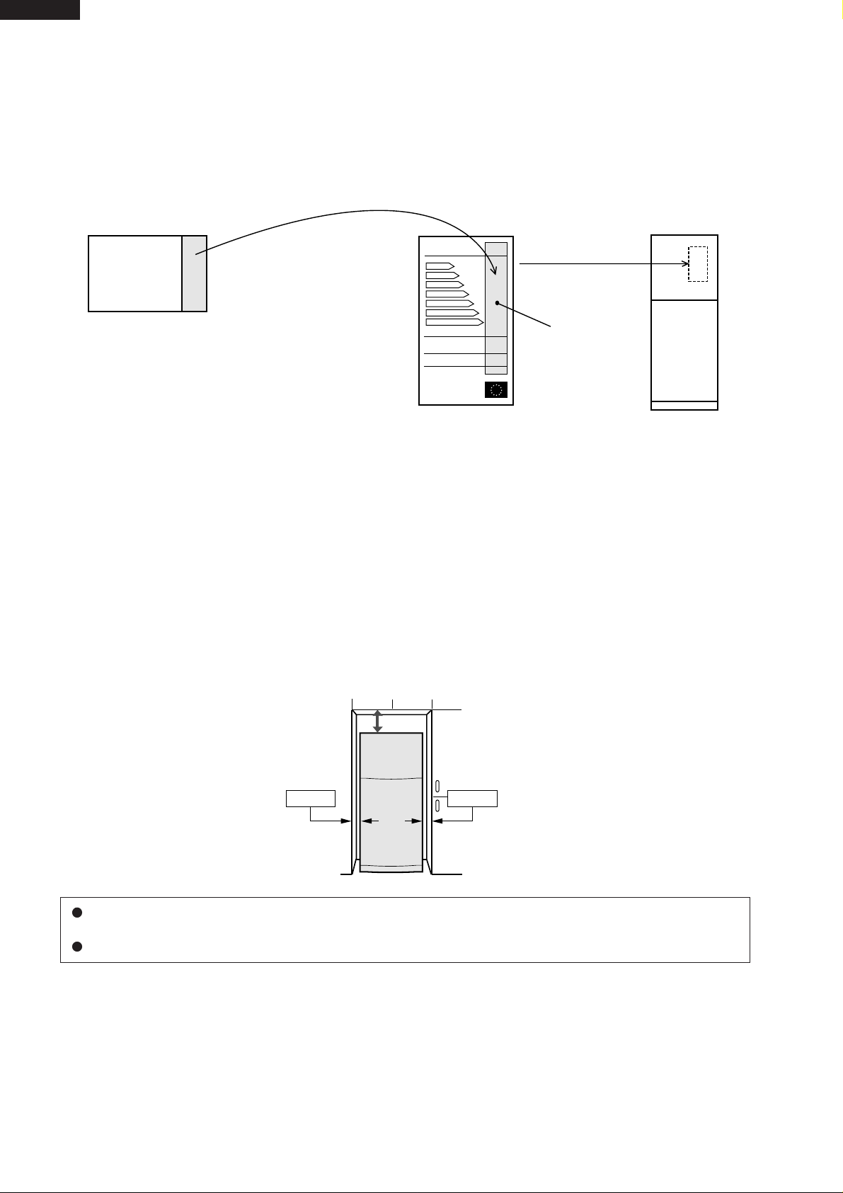
Usage of "the ENERGY LABEL"
When displaying this refrigerator in the shop-window, attach the
"ENERGY LABEL" to it in the following procedure.
Fix the data part of
"ENERGY LABEL (DATA)"
on the data part of
"ENERGY LABEL (BASE)"
"ENERGY LABEL (DATA)"
(This label is in Operation manual)
E
A
B
C
D
E
F
G
G
Data part
"ENERGY LABEL (BASE)"
of each language
Refrigerator
INSTALLATION
Free standing type
To ensure adequate ventilation for this refrigerator, install with 6 cm space at the rear and both sides, with a
minimum space of 9 cm above the refrigerator.
9cm
6cm 6cm
This refrigerator shall be used under the ordinary place condition between +5˚C and +43˚C of ambient
temperature, and also not be left under -10˚C for long days.
To be used this refrigerator within the range of the rated voltage ±6%.
2
Page 3
CAUTIONS AND INFORMATIONS
In case of following troubles, the cause is not related with the failure of refrigerator.
Please mention the correct way to the customer for the use of refrigerator when the repairing.
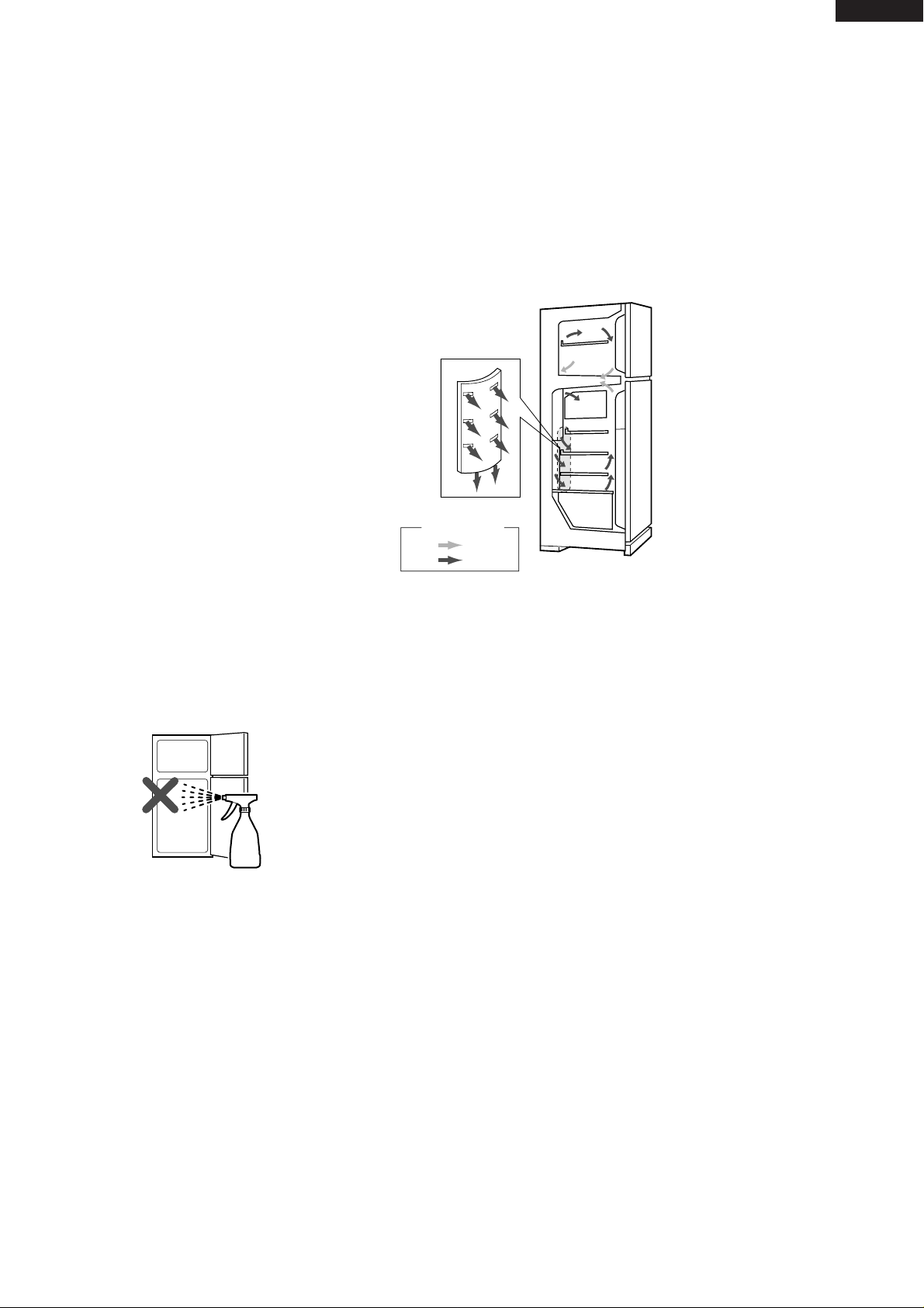
1. Some foods freezed in the refrigerator compartment.
Do not place food directly in front of
cold air outlet.
This may lead to the food freezing.
SJ-68L-T2
cold air flow
IN
OUT
2. Some plastic parts were cracked or splitted.
Some household cleaning chemicals may affect the internal
food liner and plastic parts resulting in splitting or cracks
occurring.
When cleaning all plastic parts inside this refrigerator, only
use diluted dishwashing liquid(soapy water). Make sure that
all plastic parts are thoroughly rinsed with water after cleaning.
3. IT IS NORMAL for the refrigerator to produce the following sounds.
Cracking or crunching sound;
Sound produced by expansion and contraction of inner walls and internal parts during cooling.
Squeaking sound;
Sound produced by expansion and contraction of internal parts.
Sound of flowing fluid (gurgling sound, fizzing sound);
Sound of refrigerant flowing in pipes (sound may become louder from time to time).
3
Page 4
SJ-68L-T2
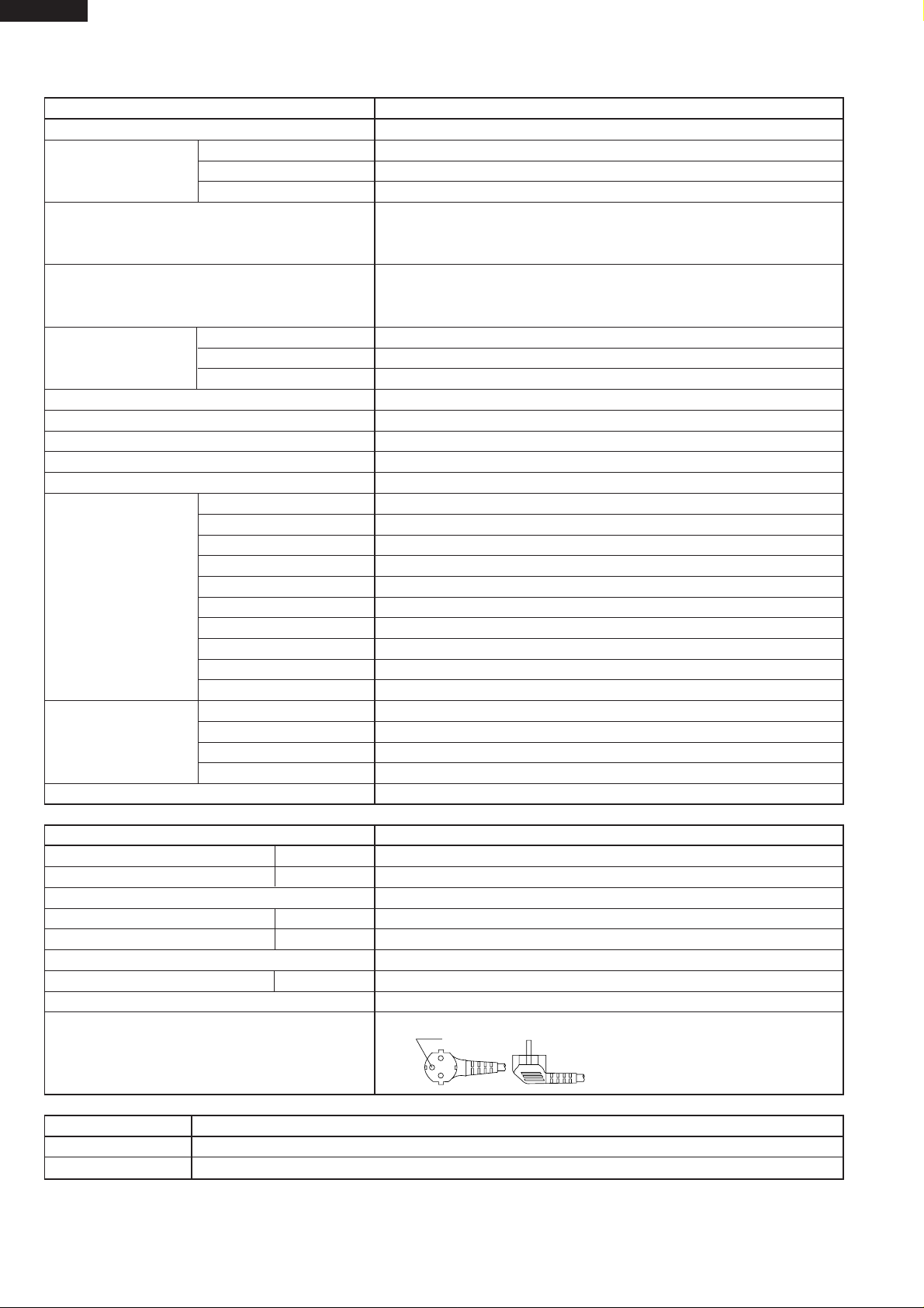
SPECIFICATIONS
Items SJ-68L-T2
Type 2-Door
Outer dimensions Height 1820mm(71.6")
(Including spacer) Width 760mm(29.9")
Depth 740mm(29.1")
Rated storage volume 577 liter (20.4cu.ft)
F: 151 liter (5.3 cu.ft)
R: 426 liter
Rated gross volume 610 liter (21.6 cu.ft)
F: 171 liter (6.1cu.ft)
R: 439 liter
Defrosting System Heater system
Start Automatic
Finish Automatic
Temperature control Automatic (Adjustable)
No-frost freezer Yes
Interior lamp 2
Caster 4
Evaporating pan 1
Refrigerator R glass shelf ass'y 3
Compartment V glass shelf ass'y 1
Vegetable case 1
Fruit case 1
R door pocket 2
Egg tray 2
Bottle pocket 2
Utility case pocket 1
Chilled case 1
Tube stand 2
Freezer Freezer shelf ass'y 1
Compartment Ice cube maker Twin ice cube maker
Ice storage box 1
F door pocket 2
Deodorizing system No
RATING
Items SJ-68L-T2
Rated voltage (V~) 220-240
Rated frequency (Hz) 50
Climate class T
Rated input (W) 170-190
Rated input of heating elements (W) 138-164
Refrigerant (Charging quantity) HFC-134a(130g)
Net Weight (kg) 88
Plug cord 3wires
Plug type CS
(15.1 cu.ft)
(15.5cu.ft)
Hole
COLOR
Items T2S
Outside color Silver
Inside color White
OPTIONAL ITEM
SJ-L838LD2 (REFRIGERATOR HINGE KITS). For changing the door to left side opening.
4
Page 5
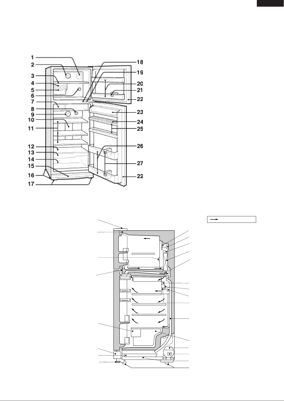
DESIGNATION OF VARIOUS PARTS
Figure D-1. External Description
SJ-68L-T2
The names are the denominations used in the
REPLACEMENT PARTS LIST.
1. Freezer light(Lamp)
2. Freezer fan
3. Freezer shelf(F shelf ass'y)
4. Ice cube maker
5. Ice cube box(Ice storage box)
6. Freezer temp. control knob
7. Chilled case
8. Refrigerator temp. control knob
9. Refrigerator fan
10. Refrigerator light(Lamp)
11. Refrigerator shelf(R glass shelf ass'y)
12. Shelf(V glass shelf ass'y)
13. Fruit case
14. Vegetable crisper(Vegetable case)
15. Evaporating pan & cover
16. Caster
17. Adjustable feet(Adjustable leg ass'y)
18. Fan & light switch(for freezer)
19. Fan & light switch(for refrigerator)
20. Freezer pocket(F door pocket)
21. Water cup
22. Magnetic door seal(Door packing)
23. Utility pocket(Utility case pocket)
24. Egg holder(Egg tray)
25. Free pocket(R door pocket)
26. Bottle pocket
27. Bottle guard(Tube stand)
Upper hinge cover
Hot pipe
Freezer temp. control knob
Hot pipe
Fruit case
Ventilating grille
Evaporating pan
Adjustable leg ass’y
Freezer
compartment
Refrigerator
compartment
Mark: Cold air flow
Freezer fan
Fan motor
Defrost thermostat
Evaporator
Defrost heater
Timer, R-fan themo. ass’y
Refrigerator fan
Damper thermostat
Refrigerator temp. control knob
Drain pipe
Vegetable case
Compressor
Starting relay, Overload relay(Protector)
Sub. condenser
Caster
Figure D-2. Constructions
5
Page 6

SJ-68L-T2
LIST OF ELECTRICAL PARTS
ITEMS TYPE NAME RATING SPECIFICATIONS
Thermostat MM1-8123 125V 6A (At normal notch)
250V 3A ON/OFF : -19/-24˚C
Defrost thermostat S101 250V 8A Open/Close : 10/1˚C
Thermo. fuse SF70E 250V 10A Working temp. : 70˚C
F-fan motor 3R00044B 220-240V 50/60Hz Working with ø100 fan
R-fan motor 3R00122A 220-240V 50/60Hz Working with ø80 fan
(R-fan fuse) 123 250V 2A Cut OFF 130˚C
Defrost heater MM6-4198 220-240V 353Ω 150W at 230V
Door switch DSD-5 250V 0.25A 4 terminals push-button type
Damper thermostat MM1-6170 — Open/Close : 3/-2˚C
Defrost timer TMDF904FD2 220-240V Integration type
50/60Hz Cycle time : 10.8/9.0 hours(50/60Hz)
Delay time : 4.3/3.6 min.(50/60Hz)
Lamp socket (F/R) — 250V 1A E-12(Hard plastic body type)
F-lamp — 240V 10W E-12
R-lamp — 240V 15W E-12
R-fan thermo. R-fan thermo.
ass'y
R-fan thermo.heater
Compressor GLY90AA 220-240V/50Hz Cooling capacity : 220kcal/h(50Hz)
S101 250V 8A Open/ Close : 7/15˚C
RSS2 350V, 2W, 10kΩ 1.1W at 230V
Main coil : 8.8Ω
Aux. coil : 14.2Ω
(at 25˚C)
Common
Aux. coil
Starting relay UH3003-7 — 14.0 Ω 30%
+
Runnig capacitor — 430VAC 5µF
Overload relay(Protector) 4TM757NFBYY — Open/ Close : 120/61˚C
Main coil
6
Page 7

THE FICHE (according to ANNEX : 94/2/EC)
SJ-68L-T2
NO.
1
Trade mark
2
Model name
3
Type
4
Energy efficiency class
5
Eco-award mark
6
Energy consumption
(220V 50Hz at 25 C)
7
Net storage volume of fresh
food storage compartment
Net storage volume of fresh
8
frozen food storage compartment
9
Star rating of frozen food
compartment
10 No frost
11
Temperature rise time
12
Freezing capacity
13
Climate class
14
Noise
Items
Description
SJ-68L
Category; 7
Refrigerator/Freezer
B
734
kWh/year
426 L
151 L
4-STAR
No frost
10 h
8 kg /24h
T
41 dB(A)
re 1 pw
Remarks
880/92
EN153
86/594/EEC
dB(A) re 1 pw
15
Maximum allowable electricity
consumption (Emax)
(96/57/EC)
1033
kWh/year
7
Page 8
SJ-68L-T2
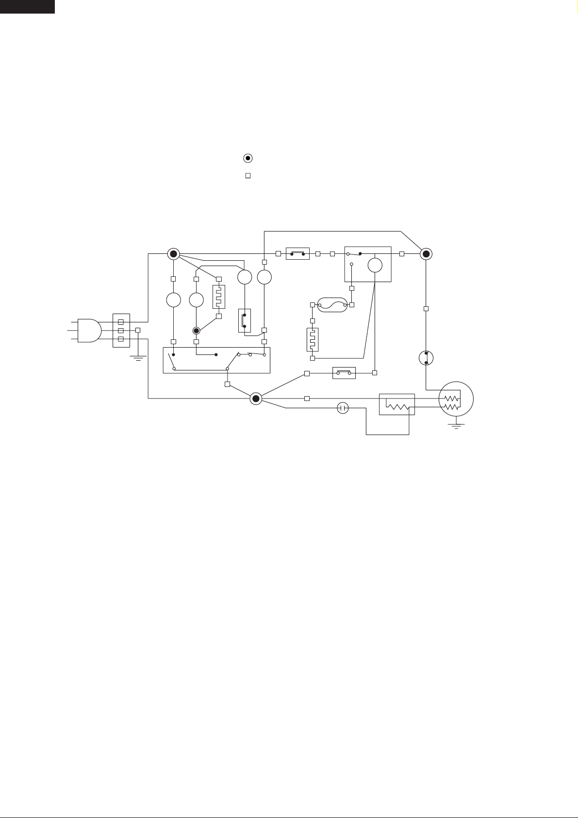
WIRING DIAGRAM
Be sure to replace the electrical parts with specified ones for maintaining the safety and performance of the set.
G
: GRAY
Br
: BROWN
O
: ORANGE
Y
: YELLOW
R
: RED
P
: PINK
B
: BLUE
Bk
: BLACK
S-B
: SKY-BLUE
G-Y
: GREEN-YELLOW
W
: WHITE
F
L
(BR)
R
L
R-FAN THERMO.
HEATER
CONNECTED IN TERMINAL BOX
CONNECTOR
F-THERMOSTAT
(W)
(R)
THERMO.
FUSE
R
F
FMFM
(G)
3
(BK)
TM
12
4
DEFROST
TIMER
SOURCE CORD
(S-B)
2
4
DOOR SWITCH
R-FAN
THERMO.
1
(O)
3
(B)
DEFROST
HEATER
DEFROST
THERMOSTAT
RUNNING
CAPACITOR
Figure W-1. Wiring Diagram
(Y)
STARTING
RELAY
PROTECTOR
COMPRESSOR
C
M
A
8
Page 9

SJ-68L-T2
REPLACEMENT PARTS LIST (SJ-68L-T2S)
REF. NO. PART NO. DESCRIPTION Q'TY CODE
SJ-68L-T2S
ELECTRIC PARTS
1-1 RTHM-A097CBEZ F-thermostat 1 AX
1-2 RSTT-A144CBE0 Starting relay 1 AW
1-3 QSWTDA035CBE0 Defrost timer 1 BB
1-4 PDMP-A046CBEZ Damper thermo 1 AX
1-5 FTHM-A028CBKZ Defrost thermo.ass’y 1 AN
1-6 RMOTRA040CBE0 Fan motor 1 AZ
1-7 QSOCAA074CBEZ Lamp socket 1 AP
1-8 RLMP-A012CBE0 Lamp 1 AH
1-9 QACC-A097CBE0 Source cord 1 AV
1-10 QSW-PA090CBZA Door switch 1 AS
1-11 RHOG-A105CBE0 Protector 1 AV
1-17 FFS-TA055CBKZ Fuse ass’y 1 AL
1-20 FW-VZA144CBEZ Lead EV-cover ass’y 1 AK
1-21 FHETBA146CBEZ Def.heater ass’y 1 AZ
1-22 FCNW-A622CBK0 Relay wire ass’y 1 AN
1-23 QCNW-A671CBE0 Reray wire RC 1 AD
1-25 QTAN-A032CBE0 Terminal block 1 AE
1-27 RMOTRA061CBEZ Fan motor 1 AW
1-28 RLMP-A029CBEZ Lamp15W 1 AH
1-29 QSOCAA072CBEZ Lamp socket 1 AN
1-30 FTHM-A029CBKZ R fan thermo ass’y 1 AQ
1-32 RC-EZA190CBEZ Running capacitor 1 AW
MECHANICAL PARTS
2-2 JKNB-A036CBFB F-temp. control knob 1 AD
2-4 LPLTMA568CBEZ Fl plate AL. 1 AF
2-7 FLEGPA077CBKZ Leg holder L ass’y 1 AQ
2-7-1 FAJS-A009CBK0 Adjustable leg ass’y 2 AD
2-7-2 LHLD-A533CBPZ Leg holder L 1 AL
2-8 FLEGPA078CBKZ Leg holder R ass’y 1 AQ
2-8-2 LHLD-A534CBPZ Leg holder R 1 AP
2-10 PSPAVA083CBEA Upper hinge spacer 1 AD
2-11 PSPAVA084CBEA Bottom hinge spacer 1 AC
2-12 PSPAVA075CBEA Center hinge spacer 1 AD
2-13 DHNG-A363CBMZ Upper hinge ass’y 1 AE
2-14 DHNG-A365CBMZ Bottom hinge R ass’y 1 AE
2-15 DHNG-A364CBMZ Center hinge R ass’y 1 AF
2-16 GCOV-A191CBFZ E.V cover 1 AS
2-17 LCRA-A010CBE0 Fan clamp 2 AD
2-19 LHLD-A389CBF0 Motor cushion 2 AF
2-20 NFANPA020CBFA Propeller fan 100 1 AE
2-21 PSEL-B845CBEZ E.V cover sealer A 1 AC
2-22 PSEL-B846CBEZ E.V cover sealer B 1 AC
2-23 PSEL-A415CBE0 E.V cover sealer C 1 AC
2-24 PCOVPA164CBFA Terminal cover 1 AE
2-25 PCOV-A253CBFA F lamp cover 1 AC
2-26 PCOV-A254CBFA R lamp cover 1 AF
2-27 GCOVPA119CBRA R-cbox cover 1 AS
2-28 HGRL-A184CBRA Fan louver 1 AU
2-29 GCOV-A162CBFL Upper hinge cover 1 AD
2-30 PCOV-A255CBFA Fan cover 2 AD
2-31 JKNB-A033CBFB R-temp.control knob 1 AD
2-36 PCAP-A077CBFA Screw cover 2 AA
2-37 PCAP-A056CBFF Screw cover B 2 AC
2-38 PGID-A156CBFZ R air guider A 1 AG
2-41 PSEL-B848CBEZ A-sealer thermo.cap 1 AC
2-49 LSTPPA108CBFA Chilled stopper 2 AC
2-50 NFANPA019CBFA Propeller fan 80 1 AM
2-51 PBOX-A121CBFA F lamp box 1 AF
2-52 PBOX-A122CBFA R lamp box 1 AM
2-53 LHLD-A536CBFA R fan motor holder A 1 AF
2-54 LHLD-A537CBFA R fan motor holder B 1 AE
2-55 HGRL-A181CBFA Multi louver L 1 AN
2-56 PFPFPB233CBFZ R-louver insu. L 1 AG
2-57 PSEL-B843CBEZ A-sealer R-louver 2 AC
2-59 PCOV-A264CBEZ F lamp box cover 1 AC
2-63 LHLD-A484CBFA Fan motor holder B 1 AH
2-64 LHLD-A485CBFA Fan motor holder A 1 AH
2-65 PSEL-B209CBE0 U-sealer handle 2 AB
2-66 PSHEMA132CBP0 Heater cover AL 1 AD
2-67 LPLTMA570CBPZ Drain support AL 1 AE
2-69 PSEL-B847CBEZ E.V cover sealer D 2 AC
9
Page 10

SJ-68L-T2
REF. NO. PART NO. DESCRIPTION Q'TY CODE
SJ-68L-T2S
2-71 PSEL-A552CBE0 Dial sealer 1 AC
2-72 PSEL-B841CBEZ Ra sealer A 2 AC
2-73 PSEL-B842CBEZ Ra sealer B 1 AC
2-74 PSEL-B122CBE0 A-sealer thermo.cap. 1 AB
2-77 LHLD-A391CBE0 SL-5N clip 1 AD
2-78 LPLTMA399CBP0 Dryer support 1 AD
2-79 LBND-A019CBE0 Nylon band 3 AB
2-80 PBOX-A071CBFA Terminal box 1 AE
2-81 PPIPPA097CBEZ Drain pipe S 1 AE
2-83 PSEL-B849CBEZ Ra sealer C 1 AC
2-84 PSEL-B850CBEZ Ra sealer D 1 AC
2-87 LBND-A018CBE0 Fastening band A 1 AP
2-90 HGRL-A179CBFA F shower duct 1 AM
2-91 HGRL-A180CBFA F return cover 2 AC
2-93 PCAP-A068CBFA C sliding cap A 2 AC
2-95 NROL-A027CBEZ V roller 2 AC
2-96 LHLD-A535CBFA Shaft holder 2 AC
2-97 LPIN-A178CB1Z Shaft 2 AC
2-99 GCOV-A192CBFG Top cover 1 AC
2-105 PSEL-B896CBEZ A-sealer FS-A 1 AC
2-106 PSEL-B897CBEZ A-sealer FS-B 2 AC
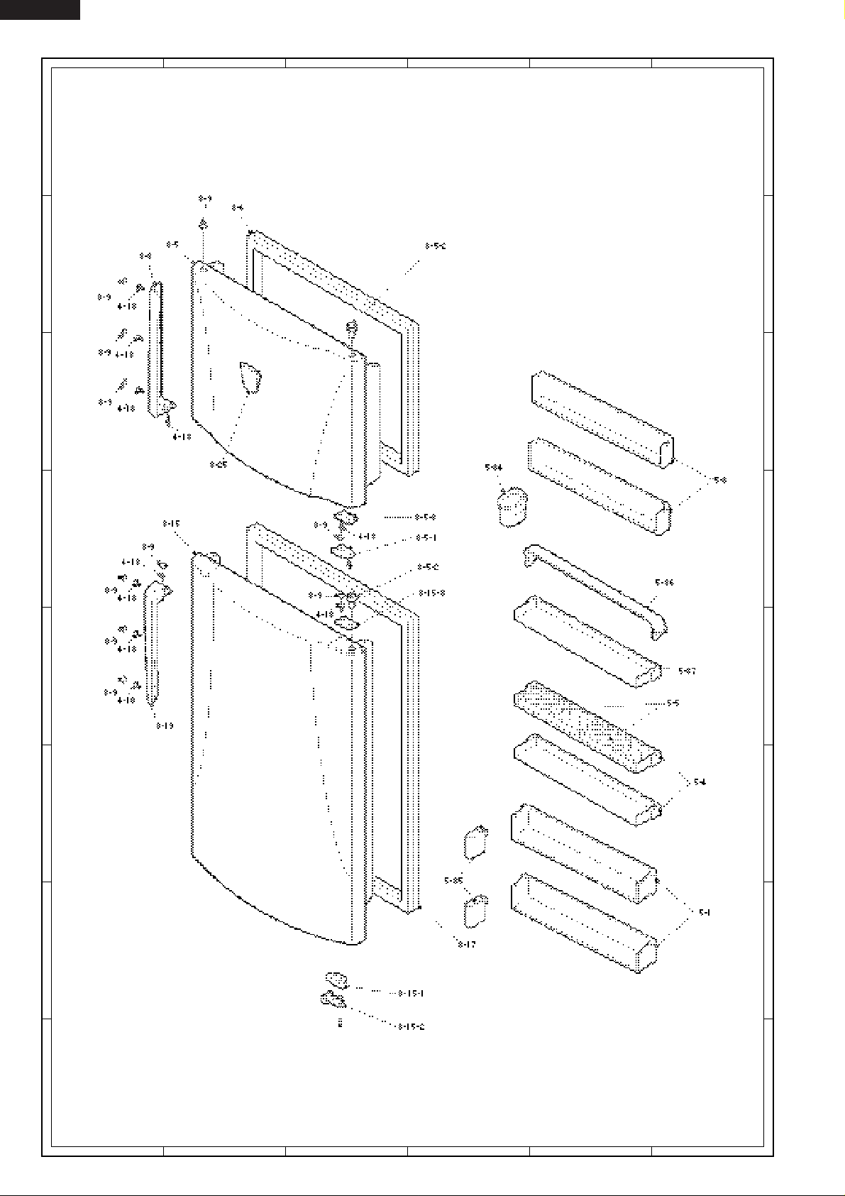
DOOR PARTS
3-5 FDORFB421CBKZ F-door ass’y 1 BL
3-5-1 LSTPPA107CBFA Fd stopper spring R 1 AD
3-5-2 NBRGPA022CBFA Nylon bearing 3S 2 AC
3-5-3 PCOV-A251CBFG DC cover FR 1 AC
3-6 FPACGA309CBKZ F-door packing 1 AX
3-8 FHNDPA056CBKZ Door handle FL ass'y 1 AP
3-9 PCAP-A067CBFG Screw cover HD 10 AC
3-15 FDORRB250CBKZ R-door ass’y 1 BS
3-15-1 LSTP-A058CBM0 R-door stopper R 1 AF
3-15-2 LSTPPA084CBFA Rd-stopper spring R 1 AD
3-15-3 PCOV-A252CBFG Dc cover RR 1 AC
3-17 FPACGA310CBKZ R-door packing 1 AY
3-19 FHNDPA057CBKZ Door handle RL ass'y 1 AP
3-25 HBDGDA894CBEA Badge 1 AM
3-26 GDAI-A059CBMZ Badge base 1 AK
OTHER PARTS
4-1 LBND-A023CBE0 L-band C 4 AC
4-3 LX-VZA003CBE0 Special screw 2 AB
4-10 QTAN-A013CBE0 Solderless term. A 4 AH
4-15 LX-BZA018CBE0 Special screw 1 AA
4-17 LX-WZA003CBE0 Washer 4 AA
4-18 LX-BZA076CBEZ Handle screw 10 AC
ATTACHMENT PARTS
5-1 UPOK-A166CBRA Bottle pocket 2 AN
5-3 UPOK-A168CBRA F door pocket 2 AP
5-4 UPOK-A165CBRA R door pocket 2 AN
5-5 UTNA-A282CBFB Egg tray 2 AG
5-6 FSRA-A193CBYZ Ice cube maker 1 AS
5-9 FSRA-A194CBKZ F shelf ass’y 1 AY
5-13 HGRL-A178CBFG Ventilating grille 1 AN
5-14 USRA-A252CBFA Drain pan 1 AN
5-15 UYOK-A330CBFA Fruit case 1 AW
5-16 UYOK-A331CBFA Vegetable case 1 AZ
5-17 UYOK-A328CBFA Ice storage box 1 AF
5-18 UYOK-A329CBFA Chilled case 1 AX
5-19 GDORPA066CBRA Chilled door 1 AP
5-24 FTNA-A301CBKZ R glass shelf ass’y 3 BC
5-25 FTNA-A302CBKZ V glass shelf ass’y 1 BC
5-26 PCAP-A076CBFG Venti.grille cap 1 AC
5-28 PCAP-A069CBFA V sliding cap L 1 AC
5-29 PCAP-A070CBFA V sliding cap R 1 AC
5-31 LRALPA132CBFA Ice tray holder L 1 AF
5-32 LRALPA133CBFA Ice tray holder R 1 AF
5-33 LRALPA134CBFA Ice tray holder B 1 AF
5-34 PCUP-A009CBFA Water cup 1 AD
5-35 UPOKPA251CBFA Tube stand 2 AG
5-36 PCOV-A259CBFA Case cover 1 AH
5-37 UPOK-A167CBRA Utility case pocket 1 AM
10
Page 11

SJ-68L-T2
REF. NO. PART NO. DESCRIPTION Q'TY CODE
SJ-68L-T2S
CYCLE PARTS
6-1 PCMPLA202CBEZ Compressor 1 BX
6-2 PSPAGA028CBE0 Rubber grommet 4 AD
6-3 FCONSA077CBKZ Sub. condenser ass’y 1 AX
6-3-1 PCOV-A256CBFA Pipe protector L 1 AF
6-3-2 PCOV-A257CBFA Pipe protector R 1 AF
6-4 FFRM-A113CBKZ Base frame ass’y 1 AW
6-5 FDRY-A006CBK0 Dryer ass’y 1 AX
6-6 PCLI-A035CBE0 Clip 1 AC
6-9 PSPAFA020CBE0 Sleeve 4 AB
6-11 PPIPCA357CBEZ S.p connector 1 AK
6-15 PGUM-A002CBF0 Absorbent rubber B 1 AH
6-18 PPIPCA252CBE0 Charge pipe 2 AD
6-21 PCOVPA165CBE0 Terminal cover 1 AF
6-27 PSEL-B899CBEZ S-sealer 2 AC
6-28 PKYU-A143CBEZ S-butyl 1 AD
6-29 PKYU-A036CBE0 Sp-butyl D-poy 1 AP
6-30 PKYU-A098CBE0 Compressor butyl 1 AG
6-31 PKYU-A035CBE0 Sp-butyl H 1 AG
MISCELLANEOUS
90-1 TINS-A472CBRZ Operation manual 1 AF
90-2 TLAB-A092CBR0 Lamp label 1 AD
90-3 SPAKCI794YDEZ Packing case 68L-3 1 BC
90-5 TLAB-A977CBEZ Case label T2S 4 AC
90-6 CPADBA765YDKZ Bottom pad ass’y 1 AY
90-7 CPADBA764YDKZ Top pad ass’y 1 AR
90-8 TLAB-A876CBRZ Warning label 1 AC
90-12 TLAB-A885CBRZ Energy label 1 AE
90-21 TLAB-A939CBRZ Caution label ROF 1 AD
HOW TO ORDER REPLACEMENT PARTS
To have your order filled promptly and correctly, please furnish the following information.
1. MODEL NUMBER 2. REF. NO.
3. PART NO. 4. DESCRIPTION
11
Page 12
SJ-68L-T2
123456
DOOR PARTS
A
B
C
A
B
C
D
E
F
D
E
F
G
H
123456
SJ-68L-T2
G
H
12
Page 13

SJ-68L-T2
123456
CABINET PARTS
A
B
C
A
B
C
D
E
F
D
E
F
G
H
123456
SJ-68L-T2
G
H
13
Page 14

SJ-68L-T2
123456
CABINET PARTS
A
B
C
A
B
C
D
E
F
D
E
F
G
H
123456
SJ-68L-T2
G
H
14
Page 15

SJ-68L-T2
15
Page 16

SJ-68L-T2
60APN3
16
2001 (01U0.11E) Printed in Japan
 Loading...