

Page 1
TopPage
R380L(W)
SERVICE MANUAL
S1701R380LPJW
MICROWAVE OVEN
HEALTHYMENUS
LOWFAT
VEGETABLES
EXPRESS
DEFROST
DEFROST
MEAL
SENSORCOOK
EASY
LESS HELP
EXPRESSMENUS
EXPRESS
QUICK&
VEGETARIAN
MEAL
EXPRESS
COOK
MEAL
RICE/
DESSERTS
PASTA
SENSOR
EASY
REHEAT
MORE
MODELS
R-380L(S)
R-380L(W)
In the interest of user-safety the oven should be restored to its
original condition and only parts identical to those specified
should be used.
CONTENTS
CHAPTER 1. BEFORE SERVICING
CHAPTER 2. WARNING TO SERVICE PERSONNEL
CHAPTER 3. PRODUCT SPECIFICATIONS
CHAPTER 4. APPEARANCE VIEW
CHAPTER 5. OPERATION SEQUENCE
CHAPTER 6. FUNCTION OF IMPORTANT COMPONENTS
CHAPTER 7. TROUBLESHOOTING GUIDE
CHAPTER 8. TEST PROCEDURES
CHAPTER 9. TOUCH CONTROL PANEL ASSEMBLY
CHAPTER 10. PRECAUTIONS FOR USING LEADFREE SOLDER
CHAPTER 11. COMPONENT REPLACEMENT AND
ADJUSTMENT PROCEDURE
CHAPTER 12. MICROWAVE MEASUREMENT
CHAPTER 13. CIRCUIT DIAGRAMS
Parts List
This document has been published to be used for
after sales service only.
The contents are subject to change without notice.
Page 2

CONTENTS
CHAPTER 1. BEFORE SERVICING
CHAPTER 2. WARNING TO SERVICE PERSONNEL
CHAPTER 3. PRODUCT SPECIFICATIONS
CHAPTER 4. APPEARANCE VIEW
CHAPTER 5. OPERATION SEQUENCE
[1] OFF CONDITION........................................ 5-1
[2] MICROWAVE COOKING CONDITION....... 5-1
[3] POWER OUTPUT REDUCTION ................ 5-1
[4] SENSOR COOKING CONDITION.............. 5-1
CHAPTER 6. FUNCTION OF IMPORTANT COMPONENTS
[1] DOOR OPEN MECHANISM ....................... 6-1
[2] 1ST. LATCH SWITCH AND 2ND. IN-
TERLOCK RELAY CONTROL SWITCH..... 6-1
[3] MONITOR SWITCH ................................... 6-1
[4] FUSE F10A................................................. 6-1
[5] HIGH VOLTAGE FUSE .............................. 6-1
[6] OVEN TEMPERATURE FUSE ................... 6-1
[7] TURNTABLE MOTOR................................. 6-1
[8] FAN MOTOR............................................... 6-1
[9] NOISE FILTER............................................ 6-1
CHAPTER 7. TROUBLESHOOTING GUIDE
CHAPTER 8. TEST PROCEDURES
[1] A: MAGNETRON (MG) TEST..................... 8-1
[2] B: POWER TRANSFORMER TEST ........... 8-2
[3] C: HIGH VOLTAGE RECTIFIER TEST....... 8-2
[4] D: HIGH VOLTAGE CAPACITOR TEST..... 8-2
[5] E: SWITCH TEST ....................................... 8-3
[6] F: TEMPERATURE FUSE TEST ................ 8-3
[7] G: MOTOR WINDING TEST....................... 8-3
[8] H: FUSE F10A ............................................ 8-3
[9] I: NOISE FILTER TEST .............................. 8-3
[10] J: HIGH VOLTAGE FUSE TEST ................. 8-4
[11] K: TOUCH CONTROL PANEL ASSEM-
BLY TEST ................................................... 8-4
[12] L: KEY UNIT (MEMBRANE SWITCH)
TEST........................................................... 8-4
[13] M: RELAY TEST ......................................... 8-5
[14] N: PROCEDURES TO BE TAKEN
WHEN THE FOIL PATTERN ON THE
PRINTED WIRING BOARD (PWB) IS
OPEN.......................................................... 8-5
[15] O: AH SENSOR TEST................................ 8-5
[3] SERVICING FOR TOUCH CONTROL
PANEL ........................................................ 9-2
CHAPTER 10. PRECAUTIONS FOR USING LEADFREE SOLDER
CHAPTER 11. COMPONENT REPLACEMENT
AND ADJUSTMENT PROCEDURE
[1] BEFORE OPERATING ..............................11-1
[2] OUTER CASE REMOVAL .........................11-1
[3] POWER TRANSFORMER REMOVAL ......11-2
[4] HIGH VOLTAGE RECTIFIER ASSEM-
BLY, HIGH VOLTAGE FUSE AND HIGH
VOLTAGE CAPACITOR REMOVAL...........11-2
[5] MAGNETRON REMOVAL .........................11-2
[6] POSITIVE LOCK CONNECTOR (NO-
CASE TYPE) REMOVAL ...........................11-2
[7] CONTROL PANEL ASSEMBLY RE-
MOVAL.......................................................11-3
[8] GRAPHIC SHEET AND MEMBRANE
SWITCH REPLACEMENT .....................
[9] TURNTABLE MOTOR REMOVAL .............11-3
[10] COOLING FAN MOTOR REMOVAL..........11-3
[11] POWER SUPPLY CORD REPLACE-
MENT.........................................................11-4
[12] 1ST. LATCH SWITCH, 2ND. INTER-
LOCK RELAY CONTROL SWITCH AND
MONITOR SWITCH ADJUSTMENT..........11-4
[13] 1ST. LATCH SWITCH, 2ND. INTER-
LOCK RELAY CONTROL SWITCH AND
MONITOR SWITCH ADJUSTMENT..........11-5
[14] DOOR REPLACEMENT ............................11-5
CHAPTER 12. MICROWAVE MEASUREMENT
CHAPTER 13. CIRCUIT DIAGRAMS
[1] Oven Schematic........................................ 13-1
[2] Pictorial Diagram....................................... 13-2
[3] Power Unit Circuit ..................................... 13-3
[4] CPU Unit Circuit........................................ 13-4
[5] LCD Circuit................................................ 13-5
[6] Printed Wiring Board (Figure S-3)............. 13-6
Parts List
....11-3
CHAPTER 9. TOUCH CONTROL PANEL ASSEMBLY
[1] OUTLINE OF TOUCH CONTROL PAN-
EL ............................................................... 9-1
[2] ABSOLUTE HUMIDITY SENSOR CIR-
CUIT............................................................ 9-1
Page 3

R380L(W)
1 – 1
R380L(W)
Service Manual
CHAPTER 1. BEFORE SERVICING
GENERAL IMPORTANT INFORMATION
This Manual has been prepared to provide Sharp Corp. Service engineers with Operation and Service Information.
It is recommended that service engineers carefully study the entire text of this manual, so they will be qualified to render satisfactory customer service.
CAUTION MICROWAVE RADIATION
DO NOT BECOME EXPOSED TO RADIATION FROM THE MICROWAVE GENERATOR OR OTHER PARTS CONDUCTING MICROWAVE
ENERGY.
Service engineers should not be exposed to the microwave energy which may radiate from the magnetron or other
microwave generating devices if it is improperly used or connected. All input and output microwave connections,
waveguides, flanges and gaskets must be secured. Never operate the device without a microwave energy absorbing
load attached. Never look into an open waveguide or antenna while the device is energized.
WARNING
Never operate the oven until the following points are ensured.
(A) The door is tightly closed.
(B) The door brackets and hinges are not defective.
(C) The door packing is not damaged.
(D) The door is not deformed or warped.
(E) There is not any other visible damage with the oven.
Servicing and repair work must be carried out only by trained service engineers.
All the parts marked " " on parts list are used at voltages more than 250V.
Removal of the outer wrap gives access to potentials above 250V.
All the parts marked "*" on parts list may cause undue microwave exposure, by themselves, or when they are damaged,
loosened or removed.
WARNING: THIS APPLIANCE MUST BE EARTHED
IMPORTANT
THE WIRES IN THIS MAINS LEAD ARE COLOURED IN ACCORDANCE WITH THE FOLLOWING CODE:
GREEN-AND-YELLOW --------------EARTH
BLUE -----------------------------------NEUTRAL
BROWN ---------------------------------------LIVE
Page 4

R380L(W)
2 – 1
R380L(W)
Service Manual
CHAPTER 2. WARNING TO SERVICE PERSONNEL
Microwave ovens contain circuitry capable of producing very high voltage and current, contact with any part of the high voltage circuit will result in
electrocution. High voltage capacitor, Power transformer, Magnetron, High voltage rectifier assembly, High voltage harness and High voltage fuse.
REMEMBER TO CHECK 3D
1) Disconnect the supply.
2) Door opened, and wedged open.
3) Discharge the high voltage capacitor.
WARNING: AGAINST THE CHARGE OF THE HIGH-VOLTAGE
CAPACITOR
The high-voltage capacitor remains charged about 60 seconds after the oven has been switched off. Wait for 60 seconds and then short-circuit the connection of the highvoltage capacitor (that is, of the connecting lead of the
high-voltage rectifier) against the chassis with the use of
an insulated screwdriver.
Sharp recommend that wherever possible fault-finding is carried out
with the supply disconnected. It may, in some cases, be necessary to
connect the supply after the outer case has been removed, in this
event carry out 3D
checks and then disconnect the leads to the primary of the power transformer. Ensure that these leads remain isolated from other components and the oven chassis. (Use insulation
tape if necessary.) When the testing is completed, carry out 3D
checks
and reconnect the leads to the primary of the power transformer.
REMEMBER TO CHECK 4R
1) Reconnect all leads removed from components during testing.
2) Replace the outer case (cabinet).
3) Reconnect the supply.
4) Run the oven. Check all functions.
Microwave ovens should not be run empty. To test for the presence of
microwave energy within a cavity, place a cup of cold water on the
oven turntable, close the door and set the microwave timer for two (2)
minutes. Set the power level to HIGH and push the START button.
When the two minutes has elapsed (timer at zero) carefully check that
the water is now hot. If the water remains cold carry out 3D
checks and
reexamine the connections to the component being tested.
When all service work is completed and the oven is fully assembled, the microwave power output should be checked and microwave leakage test
should be carried out.
Page 5

R380L(W)
3 – 1
R380L(W)
Service Manual
CHAPTER 3. PRODUCT SPECIFICATIONS
ITEM DESCRIPTION
Power Requirements
230 - 240 Volts
50 Hertz
Single phase, 3 wire earthed
Power Consumption 1.67 k W
Power Output
1200 watts nominal of RF microwave energy (IEC Test Procedure)
Operating frequency 2450 MHz
Case Dimensions
Width 520 mm
Height 310 mmincluding foot
Depth 440 mm
Turntable Diameter 320 mm
Control Complement
Touch Control System
Clock (1:00 - 12:59)
Timer (0 - 99 minutes 99 seconds)
Microwave Power for Variable Cooking
Repetition Rate;
100P ..................................................................... Full power throughout the cooking time
70P ....................................................................... approx. 70% of FULL Power
50P ....................................................................... approx. 50% of FULL Power
30P ...................................................................... approx. 30% of FULL Power
10P ....................................................................... approx. 10% of FULL Power
SENSOR COOK pads
SENSOR REHEAT pad
HEALTHY MENUS pads
EXPRESS MENUS pads
EASY DEFROST pad
QUICK AND EASY pad
NUMBER pads
POWER LEVEL pad
TIMER/CLOCK pad
STOP/CLEAR pad
INSTANT COOK/START pad
LESS/MORE pads
HELP pad
Set Weight (Approx.) 17 kg
Page 6

R380L(W)
4 – 1
R380L(W)
Service Manual
CHAPTER 4. APPEARANCE VIEW
OVEN
1. Door open button
2. Door safety latches
3. Removable turntable support
4. Removable turntable tray
5. Oven lamp
6. See through door
7. Ventilation openings
8. Touch control panel
9. Liquid crystal display
10. Coupling
11. Wave guide cover
12. Power supply cord
13. Door hinges
14. Door seal and sealing surfaces
TOUCH CONTROL PANEL
1. HEALTHY MENUS PADS
Press to select “Healthy Menus” menu.
2. NUMBER PADS
Press to enter cooking times, clock time, weight or quantity of food.
3. TIMER/CLOCK PAD
Press to set Timer and Clock.
4. POWER LEVEL PAD
Press to select microwave power setting. If not pressed, 100% is automatically
selected.
5. INSTANT COOK/START PAD
Press once to cook for 1 minute on 100% or increase by 1 minute multiples each
time this pad is pressed during manual cooking. Press to start oven after setting
programmes.
6. STOP/CLEAR PAD
Press to clear during programming. Press once to stop operation of oven during
cooking; press twice to cancel cooking programme.
7. EXPRESS MENUS PADS
Press to select “Express Menus” menus.
8. SENSOR COOK PADS
Press to select Sensor Cook menus.
9. SENSOR REHEAT PAD
Press to select a reheat menu.
10.QUICK AND EASY PAD
Press to select Quick and Easy menus.
11.EASY DEFROST PAD
Press to defrost frozen food by entering quantity.
12.MORE, LESS PADS
Press to increase/decrease the time in one minute increments during cooking or
to alter the cooking result for the automatic operations.
13.HELP PAD
Press to select auto start, child lock, demonstration modes or info on pads.
Press to get cooking information.
NOTE: Some one-touch cooking features such as “INSTANT COOK” are disabled after one minute when the oven is not in use. These fea-
tures are automatically enabled when the door is opened and closed or the STOP/CLEAR pad is pressed.
12
4
7
3
8
9
14
2
6
13
10
11
2
5
EXPRESS MENUS
DEFROST
EXPRESS
COOK
EXPRESS
MEAL
EXPRESS
MORE
LESS HELP
SENSOR COOK
QUICK&
EASY
EASY
DEFROST
SENSOR
REHEAT
RICE/
PAS TA
DESSERTS
VEGETABLES
HEALTHY MENUS
LOW FAT
MEAL
VEGETARIAN
MEAL
1
3
5
7
8
12
9
2
4
6
10
11
13
Page 7

R380L(W)
5 – 1
R380L(W)
Service Manual
CHAPTER 5. OPERATION SEQUENCE
[1] OFF CONDITION
Closing the door activates all door interlock switches (1st. latch switch
and 2nd. interlock relay control switch).
MPORTANT
When the oven door is closed, the monitor switch contacts (COM-NC)
must be open. When the microwave oven is plugged in a wall outlet,
rated voltage is supplied to the noise filter and the control unit.
Figure O-1 on page 13-1
1. The display shows “MICRO-, WAVE, OVEN” repeatedly.
2. To set any programmes or set the clock, you must first touch the
STOP/CLEAR pad.
3. “ : “ appears in the display.
NOTE: When the oven door is opened, the oven lamp comes on at
this time.
[2] MICROWAVE COOKING CONDITION
1. HIGH COOKING
Enter a desired cooking time with the touching NUMBER pad and start
the oven with touching START pad.
Function sequence
Figure O-2 on page 13-1
1. Rated voltage is supplied to the primary winding of the power trans-
former. The voltage is converted to about 3.3 volts A.C. output on
the filament winding and high voltage of approximately 2000 volts
A.C. on the secondary winding.
2. The filament winding voltage (3.3 volts) heats the magnetron fila-
ment and the high voltage (2000 volts) is sent to the voltage doubling circuit, where it is doubled to negative voltage of
approximately 4000 volts D.C.
3. The 2450 MHz microwave energy produced in the magnetron gen-
erates a wave length of 12.24 cm. This energy is channelled
through the waveguide (transport channel) into the oven cavity,
where the food is placed to be cooked.
4. When the cooking time is up, a signal tone is heard and the relays
(RY1+RY2) go back to their home position. The circuits to the oven
lamp, power transformer, fan motor and turntable motor are cut off.
5. When the door is opened during a cook cycle, the switches come to
the following condition
The circuits to the power transformer, fan motor and turntable motor
are cut off when the 1st. latch switch and 2nd. interlock relay control
switch are made open. The oven lamp remains on even if the oven
door is opened after the cooking cycle has been interrupted, because
the relay RY1 stays closed. Shown in the display is the remaining time.
6. MONITOR SWITCH CIRCUIT
The monitor switch is mechanically controlled by oven door, and
monitors the operation of the 1st. latch switch and 2nd. interlock
relay.
1) When the oven door is opened during or after the cycle of a
cooking program, the 1st. latch switch and 2nd. interlock relay
control switch must open their contacts first. After that the contacts (COM-NC) of the monitor switch can be closed.
2) When the oven door is closed, the contacts (COM-NC) of the
monitor switch must be opened. After that the contacts of the
1st. latch switch and 2nd. interlock relay control switch are
closed.
3) When the oven door is opened and the contacts of the 1st. latch
switch and 2nd. interlock relay remain closed. The fuse F10A
will blow, because the monitor switch is closed and a short circuit is caused.
2. MEDIUM HIGH, MEDIUM, MEDIUM LOW, LOW
COOKING
When the microwave oven is preset for variable cooking power, rated
voltage is supplied to the power transformer intermittently within a 32second time base through the relay contact which is coupled with the
current-limiting relay. The following levels of microwave power are
given.
SETTING;
NOTE: The ON/OFF time ratio does not exactly correspond to the
percentage of microwave power, because approx. 3 seconds
are needed for heating up the magnetron filament.
[3] POWER OUTPUT REDUCTION
After 100% power cooking mode is carried out for more than 40 minutes, the power out-put is automatically reduced to 70%.
[4] SENSOR COOKING CONDITION
Using the SENSOR function, the food is cooked without figuring time,
power level or quantity. When the oven senses enough steam from the
food, it relays the information to its microprocessor which will calculate
the remaining cooking time and power level needed for best results.
When the food is cooked, water vapor is developed. The sensor
“senses” the vapor and its resistance increases gradually. When the
resistance reaches the value set according to the menu, supplementary cooking is started. The time of supplementary cooking is determined by experiment with each food category and inputted into the
LSI.
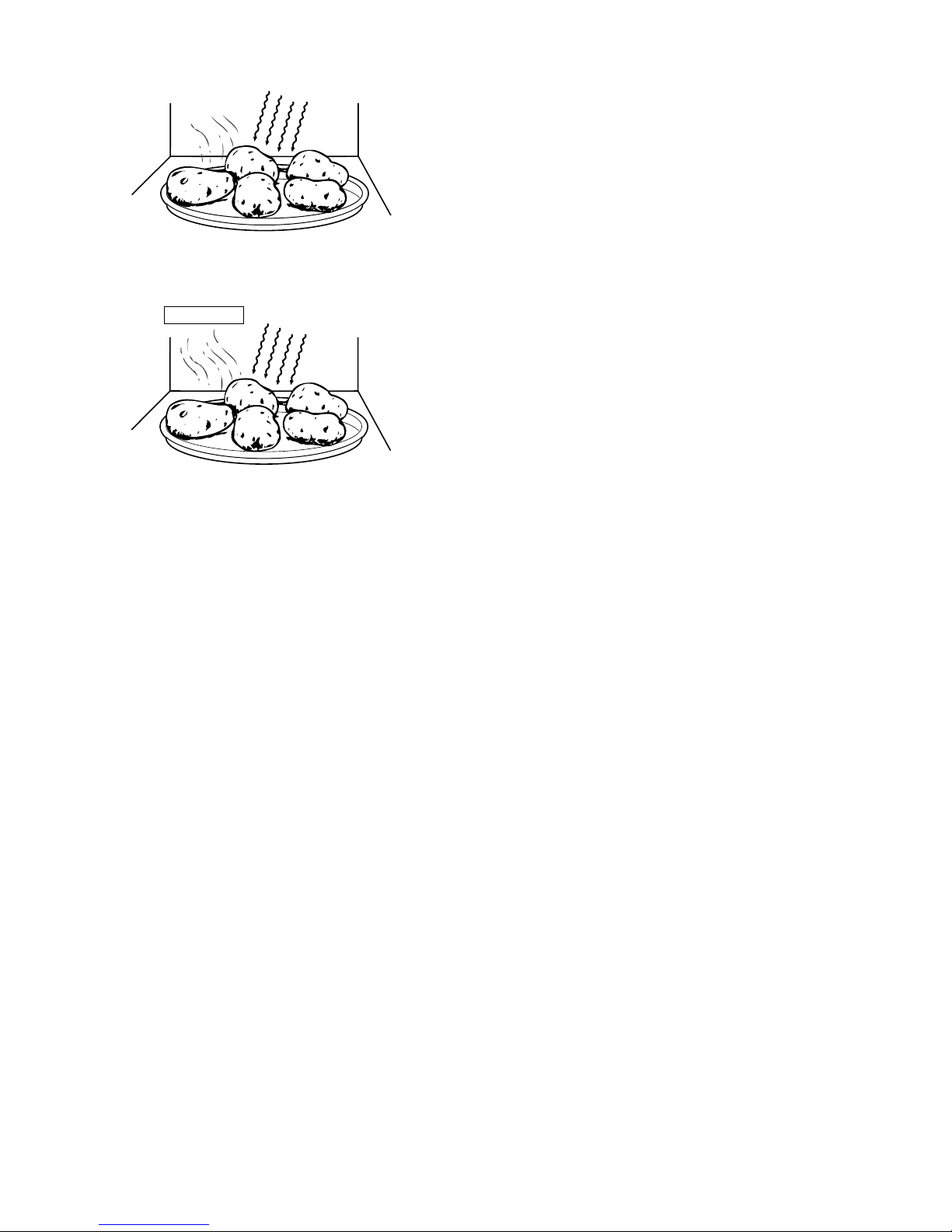
An example of how sensor works: (POTATOES)
1. Potatoes at room temperature. Vapor is emitted very slowly.
CONNECTED COMPONENTS RELAY
Oven lamp, Fan motor, Turntable motor RY1
Power transformer RY2
CONDITION
SWITCH CONTACT
DURING
COOKING
DOOR OPEN
(NO COOKING)
1st. latch switch COM-NO Closed Open
2nd. interlock relay
control switch
COM-NO Closed Open
Monitor switch COM-NC Open Closed
100P
32 sec. ON
70P
Approx. 70%
100%
24 sec. ON 8 sec. OFF
14 sec. OFF
20 sec. OFF
26 sec. OFF
50P Approx. 50%
18 sec. ON
30P
Approx. 30%
12 sec. ON
10P Approx. 10%
6 sec. ON
Page 8
R380L(W)
5 – 2
2. Heat potatoes. Moisture and humidity is emitted rapidly. You can
smell the aroma as it cooks.;
3. Sensor detects moisture and humidity and calculates cooking time
and variable power.
1. Cooking Sequence.
1. 1.Operate the oven in sensor cooking mode by referring to the
operation manual.
NOTE: The oven should not be operated on SENSOR immediately
after plugging in the unit. Wait two minutes before cooking on
SENSOR.
2. The coil of shut-off relay (RY-1) is energized, the turntable motor,
oven lamp and cooling fan motor are turned on, but the power
transformer is not turned on.
3. After about 16 seconds, the cook relay (RY-2) is energized. The
power transformer is turned on, microwave energy is produced and
first stage is started. The 16 seconds is the cooling time required to
remove any vapor from the oven cavity and sensor.
NOTE: During this first stage, do not open the door or touch STOP/
CLEAR pad.
4. When the sensor detects the vapor emitted from the food, the display switches over to the remaining cooking time and the timer
counts down to zero. At this time, the door may be opened to stir,
turn, or season food.
5. When the timer reaches zero, an audible signal sounds. The shutoff relay and cook relay are de-energized and the power transformer, oven lamp, etc. are turned off.
6. Opening the door or touching the STOP/CLEAR pad, the time of
day will reappear on the display and the oven will revert to an OFF
condition.
M
IC R OWA V E
MIC R OW A V E
AH S ENS OR
Page 9

R380L(W)
6 – 1
R380L(W)
Service Manual
CHAPTER 6. FUNCTION OF IMPORTANT COMPONENTS
[1] DOOR OPEN MECHANISM
The door is opened by pushing the open button on the control panel,
refer to the Figure D-1.When the open button is pushed, the open button pushes up the switch lever, and then the switch lever pushes up
the latch head. The latch heads are moved upward and released from
latch hook. Now the door will open.
Figure D-1. Door Open Mechanism
[2] 1ST. LATCH SWITCH AND 2ND. INTERLOCK RELAY CONTROL SWITCH
1. When the oven door is closed, the contacts (COM-NO) must be
closed.
2. When the oven door is opened, the contacts (COM-NO) must be
opened.
[3] MONITOR SWITCH
1. When the oven door is closed, the contacts (COM-NC) must be
opened.
2. When the oven door is opened, the contacts (COM-NC) must be
closed.
3. If the oven door is opened and the contacts (COM-NO) of the 1st.
latch switch and 2nd. interlock relay fail too pen, the fuse F10A
blows simultaneously with closing the contacts (COM-NC) of the
monitor switch.
CAUTION: BEFORE REPLACING A BLOWN FUSE F10ATEST THE
1ST. LATCH SWITCH, 2ND.INTERLOCK RELAY, MONITOR SWITCHAND MONITOR RESISTOR FOR PROPEROPERATION.
[4] FUSE F10A
1. The fuse F10A blows when the contacts (COM-NO) oft he 1st. latch
switch and 2nd. interlock relay remain closed with the oven door
open and when the monitors witch closes.
2. If the wire harness or electrical components are short-circuited, this
fuse F10A blows to prevent an electric shock or fire hazard.
[5] HIGH VOLTAGE FUSE
The high voltage fuse blows when the high voltage rectifier or the magnetron is shorted.
[6] OVEN TEMPERATURE FUSE
The temperature fuse, located on the top of the oven cavity, is
designed to prevent damage to the oven by fire.If the food load is overcooked, by either error in cook time or defect in the control unit, the
temperature fuse will open.Under normal operation, the temperature
fuse remains closed. However, when abnormally high temperatures
are reached within the oven cavity, the temperature fuse will open at
150°C, causing the oven to shut down.
[7] TURNTABLE MOTOR
The turntable motor drives the turntable roller assembly to rotate the
turntable.
[8] FAN MOTOR
The fan motor drives a blade which draws external cool air.This cool
air is directed through the air vents surrounding the magnetron and
cools the magnetron. This air is channelled through the oven cavity to
remove steam and vapours given off from the heating foods. It is then
exhausted through the exhausting air vents at the oven cavity.
[9] NOISE FILTER
The noise filter prevents the radio frequency interference that might
flow back in the power circuit.
Latch Hook
Monitor Switch
2nd. Interlock
Relay Control
Switch
1st Latch Switch
Latch
Heads
Door
Page 10
R380L(W)
7 – 1
R380L(W)
Service Manual
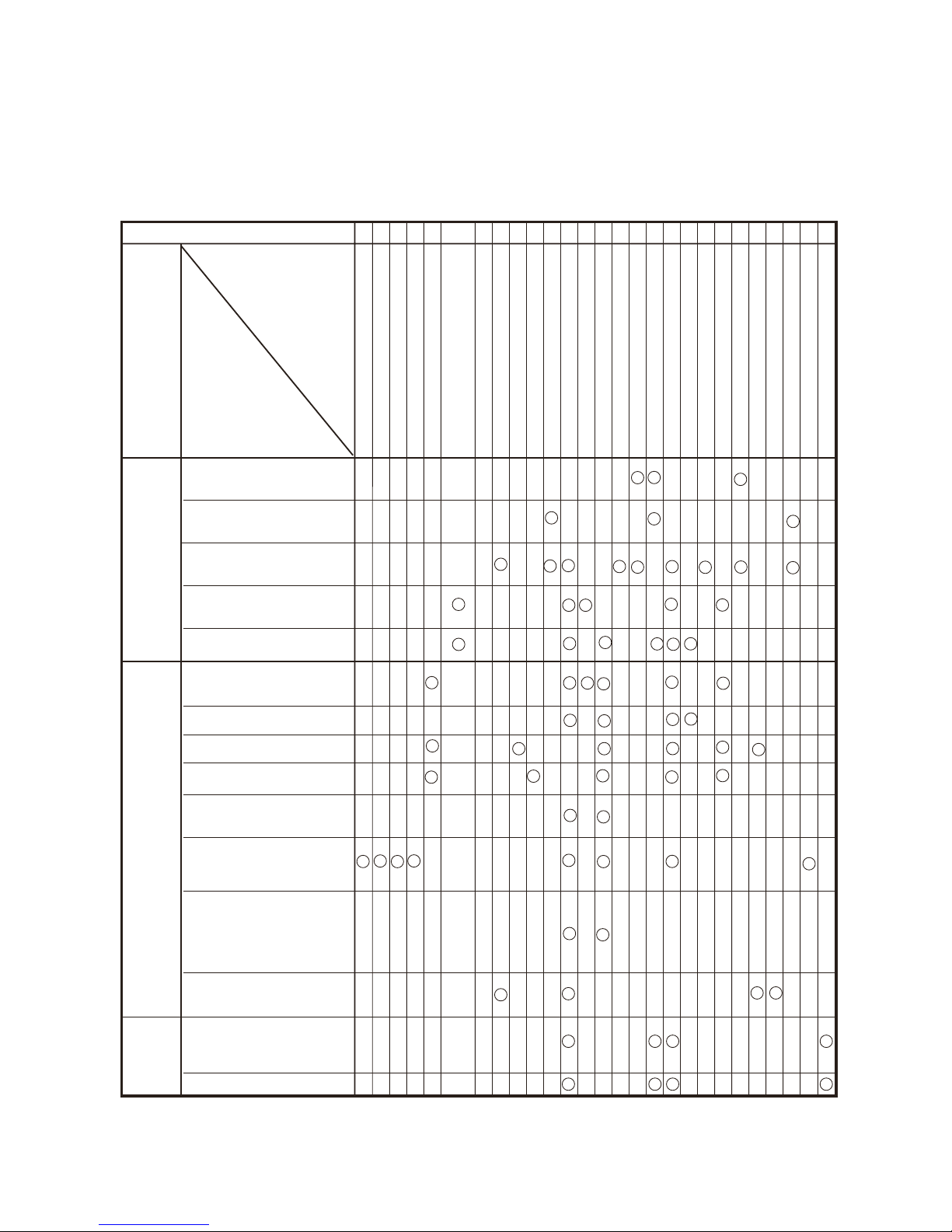
CHAPTER 7. TROUBLESHOOTING GUIDE
When troubleshooting the microwave oven, it is helpful to follow the
Sequence of Operation in performing the checks. Many of the possible
causes of trouble will require that a specific test be performed. These
tests are given a procedure letter which will be found in the “Test Procedure”section.
IMPORTANT:
If the oven becomes inoperative because of a blown fuse F10A in the
1st. latch switch - 2nd. interlock relay - monitor switch circuit, check the
1st. latch switch, 2nd.interlock relay and monitor switch before replacing the fuse F10A.
MAGNETRON
POWER TRANSFORMER
H.V. RECTIFIER ASSEMBLY
HIGH VOLTAGE CAPACITOR
1ST. LATCH SWITCH
2ND. INTERLOCK RELAY CONTROL
SWITCH
MONITOR SWITCH
TEMPERATURE FUSE (OVEN)
FAN MOTOR
TURNTABLE MOTOR
FUSE F10A
TOUCH CONTROL PANEL
KEY UNIT
RELAY (RY-1, RY-2)
FOIL PATERN ON P.W.B.
POWER SUPPLY CORD
SHORTED WIRE HARNESS
OPENED WIRE HARNESS
OVEN LAMP
WALL OUTLET
MISADJUSTMENT SWITCH
HOME FUSE OR BREAKER
BLOCKED COOLING FAN
BLOCKED VENTILATION
NOISE FILTER
HIGH VOLTAGE FUSE
AH SENSOR
TEST PROCEDURE
CK = Check / RE = Replace
ABC
D
EEEFGGHKLMN
RE CK CK RE CK CK CK CK CK
IJO
CONDITION
PROBLEM
POSSIBLE CAUSE
AND
DEFECTIVE PARTS
ON
SENSO
RCOOKING
CONDITION
CONDITION
OFF
CONDITION
Home fuse blows when power
supply cord is plugged into wall
outlet.
FUSE F10A blows when power
supply cord is plugged into wall
outlet.
Display does not show anything
when power supply cord is plugged into wall outlet.
Display does not operate properly when STOP/CLEAR pad is
touched.
Oven lamp does not light at door
opened. (Display appears.)
Oven lamp does not light (Display appears.)
Fan motor does not operate.
(Display appears.)
Turntable motor assembly does
not operate. (Display appears.)
Oven does not start when the
START pad is touched. (Display appears)
Oven or any electrical parts does
not stop when cooking time is 0
or STOP/CLEAR pad is touched.
Oven goes into cook cycle but
shuts down before end of cooking cycle.
Oven stops at 16 sec. after starting.
AH sensor does not end during
Sensor cooking condition. (Oven
doesnot shut off after a cup of water is boiling by sensor cooking.)
Oven seems to be operating but
littleornoheatisproducedin
oven load. (Microwave power level is set at 100%)
Oven does not seems to be operating properly when 70%, 50%,
30% or 10% is set. (Oven operates properly a t 100% and then
the STOP/CLEAR pad is touched
theovenstops.)
Page 11

R380L(W)
8 – 1
R380L(W)
Service Manual
CHAPTER 8. TEST PROCEDURES
[1] A: MAGNETRON (MG) TEST
NEVER TOUCH ANY PART IN THE CIRCUIT WITH YOUR HAND OR AN INSULATED TOOL WHILE THE OVEN IS IN OPERATION.
CARRY OUT 3D
CHECKS.
Isolate the magnetron from the high voltage circuit by removing all leads connected to the filament terminal.
To test for an open circuit filament use an ohmmeter to make a continuity test between the magnetron filament terminals, the meter should show a
reading of less than 1 ohm.
To test for a short circuit filament to anode condition, connect ohmmeter between one of the filament terminals and the case of the magnetron
(ground). This test should be indicated an infinite resistance. If a low or zero resistance reading is obtained then the magnetron should be replaced.
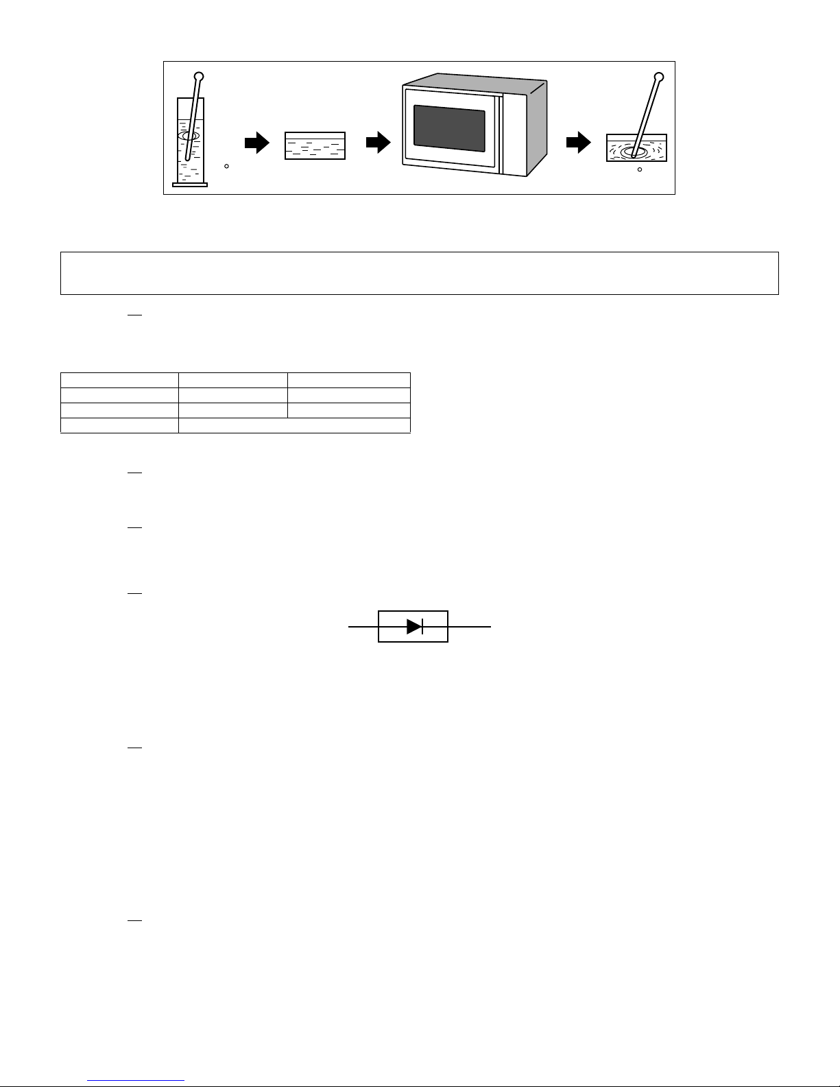
MICROWAVE OUTPUT POWER (1 litre water load)
The following test procedure should be carried out with the microwave oven in a fully assembled condition (outer case fitted). Microwave output power
from the magnetron can be measured by IEC test procedure, i.e. it can be measured by using water load how much it can be absorbed by the water
load. To measure the microwave output power in the microwave oven, the relation of calorie and watt is used. When P(W) heating works for t (sec-
ond), approximately P x t/4.187 calorie is generated. On the other hand, if the temperature of the water with V(ml) rises T (°C) during this microwave
heating period, the calorie of the water is v x T.
Measuring condition:
1) Container
The water container must be a cylindrical borosilicate glass vessel having a maximum material thickness of 3 mm and an outside diameter of
approximately 190 mm.
2) Temperature of the oven and vessel
The oven and the empty vessel are at ambient temperature prior to the start of the test.
3) Temperature of the water
The initial temperature of the water is (10±1)°C
4) Select the initial and final water temperature so that the maximum difference between the final water temperature and the ambient temperature is
5°C.
5) Select stirring devices and measuring instruments in order to minimize addition or removal of heat.
6) The graduation of the thermometer must be scaled by 0.1°C at minimum and an accurate thermometer.
7) The water load must be (1000±5) g.
8) “t” is measured while the microwave generator is operating at full power. Magnetron filament heat-up time is not included.
NOTE: The operation time of the microwave oven is “t + 3" sec. 3 sec. is magnetron filament heat-up time.
Measuring method:
1) 1.Measure the initial temperature of the water before the water is added to the vessel.
(Example: The initial temperature T1 = 11°C)
2) Add the 1 litre water to the vessel.
3) Place the load on the centre of the shelf.
4) Operate the microwave oven at 100% for the temperature of the water rises by a value T of 10°C.
5) Stir the water to equalize temperature throughout the vessel.
6) Measure the final water temperature. (Example: The final temperature T2 = 21°C)
7) Calculate the microwave power output P
in watts from above formula.
JUDGEMENT: The measured output power should be at least ± 15% of the rated output power.
CAUTION: 1°C CORRESPONDS TO 120 WATTS. REPEAT MEASUREMENT IF THE POWER IS INSUFFICIENT.
The formula is as follows;
P x t / 4.187 = V x T+ 0.55 x mc (T2-T0)/4.187 P (W) = 4.187 x V x T / t + 0.55 x mc (T2-T0)/t
Our condition for water load is as follows:
Room temperature (T0) ......................... around 20°C Power supply ........................... VoltageRated voltage
Water load .........................................................1000 g Initial temperature (T1) .................................... 10±1°C
Heating time ..................................................... 35 sec. Mass of container (mc) ...................................... 330 g
T2 .................................................... Final Temperature T = T2 - T1 P = 120 x T + 0.55 x mc (T2-T0)/35
Room temperature ................................................................... To = 21°C
Initial temperature ..................................................................... T1 = 11°C
Temperature after (35+ 3) = 38 sec. ..................................... T2 = 21°C
Temperature difference Cold-Warm ( T = T2 - T1) .......... T = 10°C
Measured output power
The equation is "P = 120 x T" .................... P = 120 x 10°C = 1200 Watts
Page 12
R380L(W)
8 – 2
[2] B: POWER TRANSFORMER TEST
CARRY OUT 3D CHECKS.
Disconnect the leads to the primary winding of the power transformer. Disconnect the filament and secondary winding connections from the rest of the
HV circuitry. Using an ohmmeter, set on a low range, it is possible to check the continuity of all three windings. The following readings should be
obtained:
If the reading obtained are not stated as above, then the power transformer is probably faulty and should be replaced.
CARRY OUT 4R
CHECKS.
[3] C: HIGH VOLTAGE RECTIFIER TEST
CARRY OUT 3D CHECKS.
Isolate the high voltage rectifier assembly from the HV circuit. The high voltage rectifier can be tested using an ohmmeter set to its highest range.
Connect the ohmmeter across the terminal of the high voltage rectifier and note the reading obtained. Reverse the meter leads and note this second
reading. The normal resistance is infinite in one direction and more than 100 kΩ in the other direction.
CARRY OUT 4R
CHECKS.
NOTE: FOR MEASUREMENT OF THE RESISTANCE OF THE RECTIFIER, THE BATTERIES OF THE MEASURING INSTRUMENT MUST HAVE
A VOLTAGE AT LEAST 6 VOLTS, BECAUSE OTHERWISE AN INFINITE RESISTANCE MIGHT BE SHOWN IN BOTH DIRECTION.
[4] D: HIGH VOLTAGE CAPACITOR TEST
CARRY OUT 3D CHECKS.
1. Isolate the high voltage capacitor from the circuit.
2. Continuity check must be carried out with measuring instrument which is set to the highest resistance range.
3. A normal capacitor shows continuity for a short time (kick) and then a resistance of about 10MΩ after it has been charged.
4. A short-circuited capacitor shows continuity all the time.
5. An open capacitor constantly shows a resistance about 10 MΩ because of its internal 10MΩ resistance.
6. When the internal wire is opened in the high voltage capacitor shows an infinite resistance.
7. The resistance across all the terminals and the chassis must be infinite when the capacitor is normal.
If incorrect reading are obtained, the high voltage capacitor must be replaced.
CARRY OUT 4R
CHECKS.
WARNING: High voltages and large currents are present at the secondary winding and filament winding of the power transformer. It is
very dangerous to work near this part when the oven is on. NEVER make any voltage measurements of the high-voltage circuits, including the magnetron filament.
RTRN-A756WRZZ RTRN-A709WRZZ
Primary winding approx. 1.34Ω approx. 1.25Ω
Secondary winding approx. 104.6Ω approx. 101.9Ω
Filament winding less than 1Ω
1000g
1000g
1000g
T1 C
T2 C
Heat up for 38 sec.
B
C
HIGH VOLTAGE RECTIFIER
Page 13

R380L(W)
8 – 3
[5] E: SWITCH TEST
CARRY OUT 3D CHECKS.
Isolate the switch to be tested and using an ohmmeter check between the terminals as described in the following table.
If incorrect readings are obtained, make the necessary switch adjustment or replace the switch.
CARRY OUT 4R
CHECKS.
[6] F: TEMPERATURE FUSE TEST
CARRY OUT 3D CHECKS.
Disconnect the leads from the terminals of the temperature fuse. Then using an ohmmeter, make a continuity test across the two terminals as
described in the below.
If incorrect readings are obtained, replace the temperature fuse.
An open circuit temperature fuse (OVEN) indicates that the foods in the oven may catch fire, this maybe due to over heating produced by improper
setting of the cooking time or failure of the control panel.
CARRY OUT 4R
CHECKS.
[7] G: MOTOR WINDING TEST
CARRY OUT 3D CHECKS.
Disconnect the leads from the motor. Using an ohmmeter, check the resistance between the two terminals as described in the table below.
If incorrect readings are obtained, replace the motor.
CARRY OUT 4R
CHECKS.
[8] H: FUSE F10A
CARRY OUT 3D CHECKS.
1. If the fuse F10A is blown, there could be shorts or ground in electrical parts or wire harness.Check them and replace the defective parts or repair
the wire harness.
2. If the fuse F10A is blown when the door is opened, check the 1st. latch switch, 2nd. interlock relay and monitor switch.
If the fuse F10A is blown by incorrect door switching replace the defective switch(s) and the fuseF10A.
CARRY OUT 4R
CHECKS.
CAUTION: ONLY REPLACE FUSE F10A WITH THE CORRECT VALUE REPLACEMENT.
[9] I: NOISE FILTER TEST
CARRY OUT 3D CHECKS.
Disconnect the leads from the terminals of the noise filter. Using an ohmmeter, check
between the terminals as described in the following table.
If incorrect readings are obtained, replace the noise filter unit.
CARRY OUT 4R
CHECKS.
Table: Terminal Connection of Switch
Plunger Operation Common terminal to Normally open terminal Common terminal to Normally close terminal
Released Open circuit Short circuit
Depressed Short circuit Open circuit.
Table: Temperature Fuse Test
Parts Name
Temperature of “ON” condition
(closed circuit).
Temperature of “OFF” condition
(open circuit).
Indication of ohmmeter (When room
temperature is approx. 20°C.)
Temperature fuse 150°C This is not resetable type. Above 150°C Closed circuit
Table: Resistance of Motor
Motors
Fan motor Turntable motor
RMOTEA405WRZZ RMOTEA390WRE0 RMOTDA253WRZZ RMOTDA265WRZZ RMOTDA173WRE0
Resistance Approximately 388Ω Approximately 252Ω Approximately 14.5kΩ Approximately 14.7kΩ Approximately 12.2kΩ
MEASURING POINT INDICATION OF OHMMETER
Between N and L Open circuit
Between terminal N and WHITE Short circuit
Between terminal L and RED Short circuit
RED
WHT
FUSE
F10A
N
L
LINE CROSS CAPACITOR
0.068μ/AC250V
NOISE SUPPRESSION COIL
LINE BYPASS CAPACITOR
0.0022μ/AC250V
LINE BYPASS CAPACITOR
0.0022μ/AC250V
Page 14

R380L(W)
8 – 4
[10] J: HIGH VOLTAGE FUSE TEST
CARRY OUT 3D CHECKS.
If the high voltage fuse is blown, there could be a short in the high voltage rectifier or the magnetron.
Check them and replace the defective parts and the high voltage fuse.
CARRY OUT 4R
CHECKS.
CAUTION: ONLY REPLACE HIGH VOLTAGE FUSE WITH THE CORRECT VALUE REPLACEMENT.
[11] K: TOUCH CONTROL PANEL ASSEMBLY TEST
The touch control panel consists of circuits including semiconductors such as LSI, ICs, etc. Therefore, unlike conventional microwave ovens, proper
maintenance cannot be performed with only a voltmeter and ohmmeter. In this service manual, the touch control panel assembly is divided into two
units, Control Unit and Key Unit, and also the Control Unit is divided into two units, CPU Unit and Power Unit, and troubleshooting by unit replacement
is described according to the symptoms indicated.
1. Key Unit. Note: Check key unit ribbon connection before replacement.
The following symptoms indicate a defective key unit. Replace the control unit assembly.
1) When touching the pads, a certain pad produces no signal at all.
2) When touching a number pad, two figures or more are displayed.
3) When touching the pads, sometimes a pad produces no signal.
2. Control Unit.
The following symptoms indicate a defective control unit. Before replacing the control unit, perform the Key unit test (Procedure L) to determine if
control unit is faulty.
1) In connection with pads.
a) When touching the pads, a certain group of pads do not produce a signal.
b) When touching the pads, no pads produce a signal.
2) In connection with indicators.
a) At a certain digit, all or some segments do not light up.
b) At a certain digit, brightness is low.
c) Only one indicator does not light up.
d) The corresponding segments of all digits do not light up; or they continue to light up.
e) Wrong figure appears.
f) A certain group of indicators do not light up.
g) The figure of all digits flicker.
3) Other possible troubles caused by defective control unit.
a) Buzzer does not sound or continues to sound.
b) Clock does not operate properly.
c) Cooking is not possible.
[12] L: KEY UNIT (MEMBRANE SWITCH) TEST
If the display fails to clear when the STOP/CLEAR pad is depressed, first verify the flat ribbon cable is making good contact, verify that the 2nd. interlock relay control switch operates properly; that is the contacts are closed when the door is closed and open when the door is open. If the 2nd. interlock relay control switch is good, disconnect the flat ribbon cable that connects the key unit to the control unit and make sure the 2nd. interlock relay
control switch is closed (either close the door or short the 2nd. interlock relay control switch connector). Use the key unit matrix indicated on the control panel schematic and place a jumper wire between the pins that correspond to the STOP/CLEAR pad making momentary contact.If the control unit
responds by clearing with a beep the key unit is faulty and must be replaced. If the control unit does not respond, it is faulty and must be replaced. If
a specific pad does not respond, the above method may be used (after clearing the control unit) to determine if the control unit or keypad is at fault.
G1 G2 G3 G4 G5 G6 G7 G8
G9
G10
G11
G12
MORE HELP
3
2
1
65 4
7
8
9
0
LOW FAT
MEAL
POWER
LEVEL
TIMER
CLOCK
QUICK&
EASY
RICE/PASTA
EXPRESS
COOK
VEGETARIAN
MEAL
INSTANT COOK
START
STOP
CLEAR
SENSOR
REHEAT
DESSERTS
EXPRESS
MEAL
LESS
EASY
DEFROST
VEGETABLES
EXPRESS
DEFROST
Page 15

R380L(W)
8 – 5
[13] M: RELAY TEST
CARRY OUT 3D CHECKS.
Remove the outer case and check voltage between the cabinet side terminal of the relay RY1 and the lower side terminal of the relay RY2 on the
power unit with an A.C. voltmeter. The meter should indicate 230 - 240 volts, if not check oven circuit.
RY1 and RY2 Relay Test
These relays are operated by D.C. voltage
Check voltage at the relay coil with a D.C. voltmeter during the microwave cooking operation.
DC. voltage indicated ................................... Defective relay.
DC. voltage not indicated ............................. Check diode which is connected to the relay coil. If diode is good, control unit is defective.
CARRY OUT 4R
CHECKS.
[14] N: PROCEDURES TO BE TAKEN WHEN THE FOIL PATTERN ON THE PRINTED WIRING
BOARD (PWB) IS OPEN
To protect the electronic circuits, this model is provided with a fine foil pattern added to the primary on the PWB, this foil pattern acts as a fuse. If the
foil pattern is open, follow the troubleshooting guide given below for repair.
CARRY OUT 3D
CHECKS.
NOTE: *At the time of making these repairs, make a visual inspection of the varistor.
Check for burned damage and examine the transformer with a tester for the
presence of layer short-circuit (check the primary coil resistance). If any abnormal condition is detected, replace the control unit.
CARRY OUT 4R
CHECKS.
[15] O: AH SENSOR TEST
Checking the initial sensor cooking condition
WARNING: The oven should be fully assembled before following procedure.
1) The oven should be plugged in at least two minutes before sensor cooking.
2) Room temperature should not exceed 35°C.
3) The unit should not be installed in any area where heat and steam are generated. The unit should not be installed, for example, next to a conventional surface unit. Refer to the “INSTALLATION Instructions”.
4) Exhaust vents are provided on the back of the unit for proper cooling and air flow in the cavity. To permit adequate ventilation, be sure to install so
as not to block these vents. There should be some space for air circulation.
5) Be sure the exterior of the cooking container and the interior of the oven are dry. Wipe off any moisture with a dry cloth or paper towel.
6) The Sensor works with food at normal storage temperature. For example, chicken pieces would be at refrigerator temperature and canned soup at
room temperature.
7) Avoid using aerosol sprays or cleaning solvents near the oven while using Sensor settings. The sensor will detect the vapor given of by the spray
and turn off before food is properly cooked.
8) After the oven is started on sensor cooking condition, if the sensor has not detected the vapor of the food, ERROR will appear and the oven will
shut off.
Water load cooking test
WARNING: The oven should be fully assembled before following procedure.
Make sure the oven has been plugged in at least two minutes before checking sensor cook operation. The cabinet should be installed and screws
tightened.
1) Fill approximately 200 milliliters of tap water in a 1000 milliliter measuring cup.
RELAY SYMBOL OPERATIONAL VOLTAGE CONNECTED COMPONENTS
RY1 Approx. -24V D.C. Oven lamp / Turntable motor / Cooling fan motor
RY2 Approx. -24V D.C. Power transformer
STEPS OCCURRENCE CAUSE OR CORRECTION
1
The rated AC voltage is not present between the cabinet side terminal of the
relay RY1and the lower side terminal of the relay RY2.
Check supply voltage and oven power cord.
2 The rated AC voltage is present to primary side of low voltage transformer.
Low voltage transformer or secondary circuit defective.
Check and replace the control unit.
3 Only pattern at “a” is broken. *Insert jumper wire J1 and solder.
4 Pattern at “a” and “b” are broken. Replace the control unit.
RY1
VRS1
T1
RY3
(J1)
a
b
c
d
Page 16

R380L(W)
8 – 6
2) Place the container on the center of tray in the oven cavity.
3) Close the door.
4) Touch the TIMER/CLOCK pad once, the POWER LEVEL pad twice and the START pad once. And touch the number pads 1 once and the number
pad 4 once. Now, the oven is in the sensor cooking condition, and “AH20”, “SENSOR” and “COOK” will appear in the display.
5) The oven will operate for the first 16 seconds, without generating microwave energy.
When the AH sensor is defective (open or short), ERROR will appear in the display after 16 seconds cleaning time
.If ERROR appears check sensor wire connections and/or AH sensor.
NOTE: ERROR will appear if the door is opened or STOP/CLEAR pad is touched during first stage of sensor cooking.
6) After approximately 16 seconds, microwave energy is produced
If ERROR is displayed or the oven does not turn off, replace the AH sensor or check the control unit, refer to explanation below.
1. TESTING METHOD FOR AH SENSOR AND/OR CONTROL UNIT
To determine if the sensor is defective, the simplest method is to replace it with a new replacement sensor.
1) Disconnect the power supply cord, and then remove outer case.
2) Open the door and block it open.
3) Discharge high voltage capacitor.
4) Remove the AH sensor.
5) Install the new AH sensor.
6) Reconnect all leads removed from components during testing.
7) Re-install the outer case (cabinet).
8) Reconnect the power supply cord after the outer case is installed.
9) Reconnect the oven to the power supply and check the sensor cook operation as follows:
a) Fill approximately 200 milliliters of tap water in a 1000 milliliter measuring cup.
b) Place the container on the center of tray in the oven cavity.
c) Close the door.
d) Touch the TIMER/CLOCK pad once, the POWER LEVEL pad twice and the START pad once. And touch the number pads 1 once and the
number pad 4 once.
e) The control panel is in automatic Sensor operation.
f) The oven turns off automatically, and the time for detecting moisture will be displayed.
If new sensor dose not operate properly, the problem is with the control unit, and refer to explanation below.
2. CHECKING CONTROL UNIT
1) Disconnect the power supply cord, and then remove outer case.
2) Open the door and block it open.
3) Discharge high voltage capacitor.
4) Disconnect the sensor connector that is mounted to control panel.
5) Then connect the dummy resistor circuit (see fig.) to the sensor connector of control panel.
6) Disconnect the leads to the primary of the power transformer.
7) Ensure that these leads remain isolated from other components and oven chassis by using insulation tape.
8) After that procedure, re-connect the power supply cord.
9) Check the sensor cook operation proceed as follows:
a) Close the door. Touch the TIMER/CLOCK pad once, the POWER LEVEL pad twice and the START pad once. And touch the number pads 1
once and the number pad 4 once.
b) The control panel is in the sensor cooking operation.
c) After approximately 25 seconds, push plunger of select switch for more than 3 seconds. This condition is same as judgement by AH sensor.
d) After approximately 3 seconds, the display shows “X X. X X “ which is the time for detecting moisture.
If the above is not the case, the control unit is probably defective.
If the above is proper, the AH sensor is probably defective.
10)Disconnect the power supply cord, and then remove outer case.
11)Open the door and block it open.
12)Discharge high voltage capacitor.
13)Disconnect the dummy resistor circuit from the sensor connector of control panel.
14)Carry out necessary repair.
Page 17

R380L(W)
8 – 7
15)Reconnect all leads removed from components during testing and repairing.
16)Re-install the outer case (cabinet).
17)Reconnect the power supply cord after the outer case is installed. Run the oven and check all functions.
18)Carry out “Water load cooking test” again and ensure that the oven works properly.
Sensor Dummy Resistor Circuit
Plunger
NC
NO
COM
COM
NO
NC
R3 R4
R1
R2
1
2
3
F-1
F-2
F-3
To connector (F)
on Control Unit.
CONNECTOR
Page 18

R380L(W)
9 – 1
R380L(W)
Service Manual
CHAPTER 9. TOUCH CONTROL PANEL ASSEMBLY
[1] OUTLINE OF TOUCH CONTROL PANEL
The touch control section consists of the following units.
(1) Key Unit
(2) Control Unit (The Control Unit consists of Power Unit and LSI Unit).
The principal functions of these units and the signals communicated among them are explained below.
1. Key Unit
The key unit is composed of a matrix, signals generated in the LSI are sent to the key unit through P00-P07.When a key pad is touched, a signal is
completed through the key unit and passed back to the LSI through P68- P71 to perform the function that was requested.
2. Control Unit
Control unit consists of LSI, reset circuit, indicator circuit, power source circuit, relay circuit, buzzer circuit, synchronizing signal circuit, absolute
humidity sensor circuit and back light circuit.
1) Reset Circuit
This circuit generates a signal which resets the LSI to the initial state when power is supplied.
2) Indicator Circuit
This circuit consists of 25 segments and 4 common electrodes using a Liquid Crystal Display.
3) Power Source Circuit
This circuit generates voltages necessary in the control unit from the AC line voltage.In addition, the synchronizing signal is available in order to
compose a basic standard time in the clock circuit.
4) Relay Circuit
A circuit to drive the magnetron, fan motor, turntable motor and light the oven lamp.
5) Buzzer Circuit
The buzzer is responsive to signals from the LSI to emit audible sounds (key touch sound and completion sound).
6) Synchronizing Signal Circuit
The power source synchronizing signal is available in order to compose a basic standard time in the clockcircuit.It accompanies a very small error
because it works on commercial frequency.
7) 2nd. Interlock Relay Control Switch
A switch to “tell” the LSI if the door is open or closed.
8) Back Light Circuit
A circuit to drive the back light (Light emitting diodesLD1- LD4).
9) Absolute Humidity Sensor Circuit
This circuit detects moisture of the cooking food to allow its automatic cooking.
[2] ABSOLUTE HUMIDITY SENSOR CIRCUIT
1. Structure of Absolute Humidity Sensor
The absolute humidity sensor includes two thermistors as shown in the illustration. One thermistor is housed in the closed vessel filled with dry air
while another in the open vessel. Each sensor is provided with the protective cover made of metal mesh to be protected from the external airflow.
2. Operational Principle of Absolute Humidity Sensor
The figure below shows the basic structure of an absolute humidity sensor. A bridge circuit is formed by two thermistors and two resistors (R1 and
R2).The output of the bridge circuit is to be amplified by the operational amplifier.Each thermistor is supplied with a current to keep it heated at about
150°C, the resultant heat is dissipated in the air and if the two thermistors are placed in different humidity conditions they show different degrees of
heat conductivity leading to a potential difference between them causing an output voltage from the bridge circuit, the intensity of which is increased
as the absolute humidity of the air increases.Since the output is very minute, it is amplified by the operational amplifier.
Ventilation opening for sensing
Sensing part
(Open vessel)
Sensing part
(Closed vessel)
Thermistors
Page 19

R380L(W)
9 – 2
3. Detector Circuit of Absolute Humidity Sensor Circuit
This detector circuit is used to detect the output voltage of the absolute humidity circuit to allow the LSI to control sensor cooking of the unit. When the
unit is set in the sensor cooking mode, 16 seconds clearing cycle occurs than the detector circuit starts to function and the LSI observes the initial
voltage available at its AN6 terminal.With this voltage given, the switches SW1 to SW5 in the LSI are turned on in such a way as to change the resistance values in parallel with R98 ~ R102. Changing the resistance values results in that there is the same potential at both F-3 terminal of the absolute humidity sensor and AN5 terminal of the LSI. The voltage of AN6 terminal will indicate about -2.5V. This initial balancing is set up about 16
seconds after the unit is put in the Sensor Cooking mode. As the sensor cooking proceeds, the food is heated to generate moisture by which the
resistance balance of the bridge circuit is deviated to increase the voltage available at AN6 terminal of the LSI.
Then the LSI observes that voltage at AN6 terminal and compares it with its initial value, and when the comparison rate reaches the preset value
(fixed for each menu to be cooked), the LSI causes the unit to stop sensor cooking; thereafter, the unit goes in the next operationautomatically.When
the LSI starts to detect the initial voltage at AN6 terminal 16 seconds after the unit has been put in the Sensor Cooking mode, if it is not possible to
balance the bridge circuit due to disconnection of the absolute humidity sensor, ERROR will appear on the display and the cooking is stopped.
1)Absolute humidity sensor circuit
[3] SERVICING FOR TOUCH CONTROL PANEL
1. Precautions for Handling Electronic Components
This unit uses CMOS LSI in the integral part of the circuits.When handling these parts, the following precautions should be strictly followed. CMOS
LSI have extremely high impedance at its input and output terminals. For this reason, it is easily influenced by the surrounding high voltage power
source, static electricity charge in clothes, etc. and sometimes it is not fully protected by the built-in protection circuit.
In order to protect CMOS LSI.
1) When storing and transporting, thoroughly wrap them in aluminium foil. Also wrap all PW boards containing them in aluminium foil.
2) When soldering, ground the technician as shown in the figure and use grounded soldering iron and work table.
2. Servicing of Touch Control Panel
We describe the procedures to permit servicing of the touch control panel of the microwave oven and the precautions you must take when doing so.
To perform the servicing, power to the touch control panel is available either from the power line of the oven itself or from an external power source.
1. Servicing the touch control panel with power supply of the oven:
C
S
R3
R1
R2
+
-
Operational
amplifie r
Output
voltage
S:Thermistor
open vessel
C:Thermistor
closed vessel
2
Ab s o lu te h um idity ( g /m )
O
u
t
p
u
tvoltage
Ab s o lu te h um idity v s ,
output voltage cha rac teris tic
SW1
SW2
SW3
SW4
SW5
P40
P41
P42
P43
P44
LSI
(IC1)
AN5
AN6
620k
300k
150k
75k
37.4k
6
3
2
1
64
4
5
15k
15k
4.7k
1234
8765
0.01uF
0.015uF
0.01
u
F
VA : -15V
VA : -15V
R90
C90
C91
C93
C92
S
F-2
1.8k
IC2
F-1
F-3
C
3.57k
3.32k
VC : -5V
0.1
uF
C. Thermistor in
closed vessel
S. Thermistor in
open vessel
R98
R99
R96
R91
360k
R93
R92
R94
R95
D90
R100
R101
R102
R97
appro x. 1M ohm
Page 20

R380L(W)
9 – 3
CAUTION: THE HIGH VOLTAGE TRANSFORMER OF THE MICROWAVE OVEN IS STILL LIVE DURING SERVICING AND PRESENTS A HAZ-
ARD.
Therefore, before checking the performance of the touch control panel,
1) Disconnect the power supply cord, and then remove outer case.
2) Open the door and block it open.
3) Discharge high voltage capacitor.
4) Disconnect the leads to the primary of the power transformer.
5) Ensure that these leads remain isolated from other components and oven chassis by using insulation tape.
6) After that procedure, re-connect the power supply cord.
After checking the performance of the touch control panel,
1) 1)Disconnect the power supply cord.
2) Open the door and block it open.
3) Re-connect the leads to the primary of the power transformer.
4) Re-install the outer case (cabinet).
5) Re-connect the power supply cord after the outer case is installed.
6) Run the oven and check all functions.
a) On some models, the power supply cord between the touch control panel and the oven itself is so short that the two can’t be separated. For
those models, check and repair all the controls (sensor-related ones included) of the touch control panel while keeping it connected to the
oven.
b) On some models, the power supply cord between the touch control panel and the oven proper is long enough that they may be separated from
each other. For those models, it is possible to check and repair the controls of the touch control panel while keeping it apart from the oven
proper; in this case you must short both ends of the door sensing switch (on PWB) of the touch control panel with a jumper, which activates an
operational state that is equivalent to the oven door being closed. As for the sensor-related controls of the touch control panel, checking them
is possible if dummy resistor(s) with resistance equal to that of the controls are used.
2. Servicing the touch control panel with power supply from an external power source:
Disconnect the touch control panel completely from the oven proper, and short both ends of the door sensing switch (on PWB) of the touch control
panel, which activates an operational state that is equivalent to the oven door being closed. Connect an external power source to the power input
terminal of the touch control panel, then it is possible to check and repair the controls of the touch control panel it is also possible to check the sensor-related controls of the touch control panel by using the dummy resistor(s).
3. Servicing Tools
Tools required to service the touch control panel assembly.
1) Soldering iron: 60W
(It is recommended to use a soldering iron with a grounding terminal.)
2) Oscilloscope: Single beam, frequency range: DC - 10MHz type or more advanced model.
3) Others: Hand tools
4. Other Precautions
1) Before turning on the power source of the control unit, remove the aluminium foil applied for preventing static electricity.
2) Connect the connector of the key unit to the control unit being sure that the lead wires are not twisted.
3) After aluminium foil is removed, be careful that abnormal voltage due to static electricity etc. is not applied to the input or output terminals.
4) Attach connectors, electrolytic capacitors, etc. to PWB, making sure that all connections are tight.
5) Be sure to use specified components where high precision is required.
Page 21

R380L(W)
10 – 1
R380L(W)
Service Manual
CHAPTER 10. PRECAUTIONS FOR USING LEAD-FREE SOLDER
1. Employing lead-free solder
The “Main PWB” of this model employs lead-free solder. This is indicated by the “LF” symbol printed on the PWB and in the service manual. The suffix
letter indicates the alloy type of the solder.
Example:
2. Using lead-free wire solder
When repairing a PWB with the “LF” symbol, only lead-free solder should be used. (Using normal tin/lead alloy solder may result in cold soldered
joints and damage to printed patterns.)
As the melting point of lead-free solder is approximately 40°C higher than tin/lead alloy solder, it is recommend that a dedicated bit is used, and that
the iron temperature is adjusted accordingly.
3. Soldering
As the melting point of lead-free solder (Sn-Ag-Cu) is higher and has poorer wettability, (flow), to prevent damage to the land of the PWB, extreme
care should be taken not to leave the bit in contact with the PWB for an extended period of time. Remove the bit as soon as a good flow is achieved.
The high content of tin in lead free solder will cause premature corrosion of the bit. To reduce wear on the bit, reduce the temperature or turn off the
iron when it is not required.
Leaving different types of solder on the bit will cause contamination of the different alloys, which will alter their characteristics, making good soldering
more difficult. It will be necessary to clean and replace bits more often when using lead-free solder. To reduce bit wear, care should be taken to clean
the bit thoroughly after each use.
Indicates lead-free solder of tin, silver and copper
Page 22

R380L(W)
11 – 1
R380L(W)
Service Manual
CHAPTER 11. COMPONENT REPLACEMENT AND ADJUSTMENT PROCE-
DURE
[1] BEFORE OPERATING
Microwave ovens contain circuitry capable of producing very high voltage and current, contact with following parts may result in severe, possibly fatal,
electric shock.
(Example)
High Voltage Capacitor, power transformer, Magnetron, High Voltage Rectifier Assembly, High Voltage fuse, High Voltage Harness etc.
WARNING:
Avoid possible exposure to microwave energy. Please follow the instructions below before operating
the oven.
1) Disconnect the power supply cord.
2) Make sure that a definite “click” can be heard when the microwave
oven door is unlatched. (Hold the door in a closed position with one
hand, then push the door open button with the other, this causes
the latch leads to rise, it is then possible to hear a “click” as the
door switches operate.)
3) Visually check the door and cavity face plate for damage (dents,
cracks, signs of arcing etc.).
Carry out any remedial work that is necessary before operating the
oven.
Do not operate the oven if any of the following conditions exist;
1) Door does not close firmly.
2) Door hinge, support or latch hook is damaged.
3) The door gasket or seal is damaged.
4) The door is bent or warped.
5) There are defective parts in the door interlock system.
6) There are defective parts in the microwave generating and transmission assembly.
7) There is visible damage to the oven.
Do not operate the oven:
1) Without the RF gasket (Magnetron).
2) If the wave guide or oven cavity are not intact.
3) If the door is not closed.
4) If the outer case (cabinet) is not fitted.
Please refer to ”OVEN PARTS, CABINET PARTS, DOOR PARTS”, when carrying out any of the following removal procedures:
To prevent an electric shock, take the following precautions.
1. Before wiring,
1) Disconnect the power supply cord.
2) Open the door and block it open.
3) Discharge the high voltage capacitor and wait for 60 seconds.
2. Don't let the wire leads touch to the following parts;
1) High voltage parts:
Magnetron, Power transformer, High voltage capacitor, High
voltage rectifier assembly and High voltage fuse.
2) Hot parts:
Convection heater, Oven lamp, Magnetron, High voltage transformer and Oven cavity.
3) Sharp edge:
Bottom plate, Oven cavity, Weveguide flange, Chassis support
and other metallic plate.
4) Movable parts (to prevent a fault)
Fan blade, Fan motor, Switch, Switch lever, Open button.
3. Do not catch the wire leads in the outer case cabinet.
4. Insert the positive lock connector certainly until its pin is locked.
And make sure that the wire leads should not come off even if the
wire leads is pulled.
5. To prevent an error function, connect the wire leads correctly, referring to the Pictorial Diagram.
[2] OUTER CASE REMOVAL
To remove the outer case, procedure as follows.
1. Disconnect the oven from power supply.
2. Open the oven door and wedge it open.
3. Remove five (5) screws from rear and one (1) screw along the right
side edge of case.
4. Slide the entire case back out about 1 inch (3 cm) to free it from
retaining clips on the cavity face plate.
5. Lift entire case from the unit.
6. Discharge the H. V. capacitor before carrying out any further work.
7. Do not operate the oven with the outer case removed.
NOTE: Step 1, 2 and 6 form the basis of the 3D
checks.
CAUTION: DISCHARGE HIGH VOLTAGE CAPACITOR BEFORE
TOUCHING ANY OVEN COMPONENTS OR WIRING.
WARNING AGAINST HIGH VOLTAGE:
WARNING FOR WIRING
REMEMBER TO CHECK 3D
1) Disconnect the supply. 3)Discharge high voltage capacitor.
2)Door opened, and wedged open.
Page 23

R380L(W)
11 – 2
[3] POWER TRANSFORMER REMOVAL
1. REMOVAL
1. CARRY OUT 3D CHECKS.
2. Disconnect wire leads (primary) from the power transformer.
3. Disconnect the high voltage fuse from the power transformer.
4. Disconnect the filament leads from the magnetron and the high
voltage capacitor.
5. Remove four (4) screws (two (2) screws from the upper side and
two (2) screws from bottom side) holding transformer to bottom
plate.
6. Remove transformer from bottom plate.
2. RE-INSTALL
1. Rest transformer on the bottom plate with its primary terminals
toward the oven face plate.
2. Secure transformer with four (4) screws (two (2) screws from the
upper side and two (2) screws from bottom side) to bottom plate.
3. Reconnect wire leads (primary) to power transformer and filament
leads of transformer to magnetron and high voltage capacitor. And
reconnect the high voltage fuse to the power transformer. Refer to
“PICTORIALDIAGRAM”.
4. Reinstall outer case and check that oven is operating properly.
[4] HIGH VOLTAGE RECTIFIER ASSEMBLY, HIGH VOLTAGE FUSE AND HIGH VOLTAGE
CAPACITOR REMOVAL
1. CARRY OUT 3D CHECKS.
2. Disconnect the high voltage fuse from the power transformer.
3. Disconnect the high voltage wire of high voltage rectifier assembly
from the magnetron.
4. Disconnect the filament lead (short one) of the power transformer
from the high voltage capacitor.
5. Remove the one (1) screw holding capacitor holder to bottom plate.
6. Remove one (1) screw holding high voltage rectifier assembly to
capacitor holder.
7. Disconnect rectifier terminal from capacitor.
High voltage rectifier assembly is now free.
8. Disconnect the high voltage fuse from the capacitor.
The high voltage fuse is now free.
9. Remove capacitor holder. Capacitor is now free.
CAUTION: WHEN REPLACING HIGH VOLTAGE REC-TIFIER AND
HIGH VOLTAGE CAPACITOR,GROUND SIDE TERMINAL
OF THE HIGHVOLTAGE RECTIFIER MUST BE
SECUREDFIRMLY WITH A GROUNDING SCREW.
[5] MAGNETRON REMOVAL
1. REMOVAL
1. CARRY OUT 3D CHECKS.
2. Disconnect all wire leads from magnetron.
3. Remove the one (1) screw holding the chassis support to the magnetron.
4. Release the chassis support from the hole of the oven cavity front
flange.
5. Remove the two (2) screws holding air duct to magnetron and oven
cavity top plate.
6. Remove the air duct from oven.
7. Carefully remove the four (4) screws holding magnetron to
waveguide flange.
8. Remove magnetron with care so that magnetron antenna is not hit
by any metal object around antenna.
9. Now, the magnetron is free.
2. REINSTALLATION
1. Reinstall the magnetron to waveguide flange with the four (4)
screws.
2. Reinstall the air duct to the oven cavity top plate and the magnetron
with two (2) screws.
3. Insert the end of the chassis support into the hole of the oven cavity
front flange.
4. Hold the other end of the chassis support to the magnetron with the
one (1) screw.
5. Reconnect the wire leads to the magnetron. Refer to ”PICTORIAL
DIAGRAM”.
6. Reinstall outer case and check that the oven is operating properly.
CAUTION: WHEN REPLACING MAGNETRON, BESURE THE R.F.
GASKET IS IN PLACE ANDMOUNTING SCREWS ARE
TIGHTENEDSECURELY.
[6] POSITIVE LOCK CONNECTOR (NO-CASE TYPE) REMOVAL
1. CARRY OUT 3D CHECKS.
2. Push the lever of positive lock® connector.
3. Pull down on the positive lock® connector.
CAUTION: WHEN CONNECTING THE POSITIVE LOCK® CONNEC-
TORS TO THE TERMINALS, CONNECT THE POSITIVE
LOCK® SO THAT THE LEVER FACES YOU.
Figure C-1. Positive lock, connector
Terminal
Push
Pull down
1
2
Lever
Positive lock¨
connector
Page 24

R380L(W)
11 – 3
[7] CONTROL PANEL ASSEMBLY REMOVAL
1. CARRY OUT 3D CHECKS.
2. Disconnect the leads from the control unit.
3. Remove the one (1) screw holding the control panel assembly to
the oven flange.
4. Slide the control panel assembly upward and remove it.
5. Now, individual components can be removed.
[8] GRAPHIC SHEET AND MEMBRANE SWITCH REPLACEMENT
1. REMOVAL
1. CARRY OUT 3D CHECKS.
2. Remove the control panel assembly, referring to chapter of CONTROL PANEL ASSEMBLY REMOVAL.
3. Remove the four (4) screws holding the control unit to the control
panel frame. And remove the control unit.
4. Tear away the graphic sheet from the control panel frame.
5. Tear away the membrane switch from the control panel frame.
2. REINSTALL
1. Remove remaining adhesive on the control panel frame surfaces
with a soft cloth soaked in alcohol.
2. Tear the backing paper from the new membrane switch.
3. Insert the ribbon cable of the membrane switch into the slit of the
control panel frame.
4. Adjust the upper edge and right edge of the membrane switch to
the small depression on the surface of the control panel frame.
5. Attach the membrane switch to the control panel frame by rubbing
with a soft cloth not to scratch.
6. Tear the backing paper from the new graphic sheet.
7. Adjust the upper edge and right edge of the graphic sheet to the
large depression on the surface of the control panel frame.
8. Attach the graphic sheet to the control panel frame by rubbing with
a soft cloth not to scratch.
9. Insert the ribbon cable into the slit of the control unit.
10.Reinstall the control unit to the control panel frame with four (4)
screws.
11.Connect membrane switch’s ribbon cable to the connector CN-G of
the control unit.
Figure C-2.Graphic Sheet and Membrane Switch Replacement
[9] TURNTABLE MOTOR REMOVAL
1. Disconnect the power supply cord.
2. Remove turntable and turntable support from oven cavity.
3. Lay the oven on it's backside. Remove the turntable motor cover by
snipping off the material in four corners.
4. Where the corners have been snipped off bend corner areas flat.
No sharp edges must be evident after removal of the turntable
motor cover.
5. Disconnect wire leads from turntable motor.
(See “Positive lock connector removal”)
6. Remove one (1) screw holding turntable motor to oven cavity.
7. Now the turntable motor is free.
8. After replacement use the one (1) screw (XHPS740P08K00) to fit
the turntable motor cover.
[10] COOLING FAN MOTOR REMOVAL
1. REMOVAL
1. CARRY OUT 3D CHECKS.
2. Disconnect the wire leads from the fan motor.
3. Remove the two (2) screws holding the fan motor to the oven cavity
back plate.
4. Remove the fan blade from the fan motor shaft according to the following procedure.
5. Hold the edge of the rotor of the fan motor by using a pair of groove
joint pliers.
CAUTION: • Make sure that no metal pieces enter the gap between
the rotor and the stator of the fan motor because the
rotor is easily shaven by pliers and metal pieces may be
produced.
• Do not touch the pliers to the coil of the fan motor
because the coil may be cut or injured.
• Do not disfigure the bracket by touching with the pliers.
6. Remove the fan blade from the shaft of the fan motor by pulling and
rotating the fan blade with your hand.
7. Now, the fan blade will be free.
CAUTION: Do not reuse the removed fan blade because the hole (for
shaft) may be larger than normal.
8. Now, the fan motor is free.
2. INSTALLATION
1. Install the fan blade to the fan motor shaft according to the following
procedure.
Small
depression
Large depression
Membrane switch
Control panel frame
Graphic sheet
Page 25

R380L(W)
11 – 4
2. Hold the center of the bracket which supports the shaft of the fan
motor on the flat table.
3. Apply the screw lock tight into the hole (for shaft) of the fan blade.
4. Install the fan blade to the shaft of fan motor by pushing the fan
blade with a small, light weight, ball peen hammer or rubber mallet.
5. Install the fan motor assembly to the oven cavity back plate with
two (2) screws.
CAUTION: • Do not hit the fan blade strongly when installed because
the bracket may be disfigured.
• Make sure that the fan blade rotates smooth afterinstallation.
• Make sure that the axis of the shaft is not slanted.
6. Connect the wire leads to the magnetron and fan motor, referring to
the pictorial diagram.
[11] POWER SUPPLY CORD REPLACEMENT
1. REMOVAL
1. CARRY OUT 3D CHECKS.
2. Remove the single (1) screw holding the green/yellow wire to the
oven cavity back plate.
3. Disconnect the leads of the power supply cord from the noise filter,
referring to the Figure C-3(a).
4. Release the moulding cord stopper of the power supply cord from
the square hole of the oven cavity back plate, referring to the Figure C-3(b).
5. Now, the power supply cord is free.
Figure C-3(a) Power Supply Cord Replacement
2. REINSTALL
1. Insert the moulding cord stopper of power supply cord into the
square hole of the rear cabinet, referring to the Figure C-3 (b).
2. Install the earth wire lead of power supply cord to the oven cavity
back plate with one (1) screw and tight the screw.
3. Connect the brown and blue wire leads of power supply cord to the
noise filter correctly, referring to the Pictorial Diagram.
4. Re-install outer case and check that the oven is operating properly.
Figure C-3(b) Power Supply Cord Replacement
[12] 1ST. LATCH SWITCH, 2ND. INTERLOCK RELAY CONTROL SWITCH AND MONITOR
SWITCH ADJUSTMENT
1. REMOVAL
1. CARRY OUT 3D CHECKS.
2. Disconnect wire leads from the switches.
3. Remove two (2) screws holding latch hook to oven flange.
4. Remove latch hook assembly from oven flange.
5. Push outward on the two (2) retaining tabs holding switch in place.
6. Switch is now free. At this time switch lever will be free, do not lose
it.
2. REINSTALL
1. Reinstall each switch in its place. The 1st. latch and monitor
switches are in the lower position and the2nd. interlock relay control switch is in the upper position.
2. Reconnect wire leads to each switch. Refer to pictorial diagram.
3. Secure latch hook (with two (2) mounting screws) to oven flange.
4. Make sure that the monitor switch is operating properly and check
continuity of the monitor circuit. Refer to chapter “Test Procedure”
and Adjustment procedure.
Gap
Rotor
Bracket
Stator
Groove joint pliers
Coil
Shaft
Axis
Stator
Rotor
These are the positions
that should be pinched
with pliers.
Shaft
Table
Center of
bracket
Rear View
Side View
N
L
Power Supply
Cord
Oven Cavity
Back Plate
Screw
Green/Yellow
Wire
Brown Wire
Blue
Wire
Noise Filter
WHT
RED
Power Supply
Cord
Oven Cavity
Back Plate
Square
Hole
Moulding
Cord Stopper
Page 26

R380L(W)
11 – 5
[13] 1ST. LATCH SWITCH, 2ND. INTERLOCK RELAY CONTROL SWITCH AND MONITOR
SWITCH ADJUSTMENT
1. Adjustment
If the 1st. latch switch, 2nd. interlock relay control switch and monitor
switch do not operate properly due to a misadjustment, the following
adjustment should be made.
1. Loosen the two (2) screws holding latch hook to the oven cavity
front flange.
2. With door closed, adjust latch hook by moving it back and forth,
and up and down. In and out play of the door allowed by the upper
and lower position of the latch hook should be less than 0.5mm.
The vertical position of the latch hook should be adjusted so that
the 1st.latch switch and 2nd. interlock relay control switch are activated with the door closed. The horizontal position of the latch hook
should be adjusted so that the plunger of the monitor switch is
pressed with the door closed.
3. Secure the screws with washers firmly.
4. Check all switches operation. If each switch has not activated with
the door closed, loosen screw and adjust the latch hook position.
2. After adjustment, check the following.
1. n and out play of door remains less than 0.5mm when in the
latched position. First check upper position of latch hook, pushing
and pulling upper portion of door toward the oven face. Then check
lower portion of the latch hook, pushing and pulling lower portion of
the door toward the oven face. Both results (play in the door)
should be less than 0.5mm.
2. The 1st. latch switch and 2nd. interlock relay controls witch interrupt the circuit before the door can be opened.
3. Monitor switch contacts close when door is opened.
4. Reinstall outer case and check for microwave leakage around door
with an approved microwave survey meter.(Refer to Microwave
Measurement Procedure.)
Figure C-4. Latch Switch Adjustments
[14] DOOR REPLACEMENT
1. REMOVAL
1. Disconnect the power supply cord.
2. Open the door slightly.
3. Insert a putty knife (thickness of about 0.5mm) into the gap
between the choke cover and door frame as shown in Figure C-5 to
free engaging parts.
4. Pry the choke cover by inserting a putty knife as shown Figure C-5.
5. Release choke cover from door panel.
6. Now choke cover is free.
NOTE: When carrying out any repair to the door, do not bend or
warp the slit choke (tabs on the door panel assembly) to
prevent microwave leakage.
Figure C-5. Door Disassembly
7. Release two (2) pins of door panel from two (2) holes of upper and
lower oven hinges by lifting up.
8. Now, door panel with door frame is free from oven cavity.
9. Release door panel from ten (10) tabs of door frame.
10.Now, door panel with sealer film is free.
11.Tear sealer film from door panel.
12.Now, door panel is free.
13.Slide latch head upward and remove it from door frame with releasing latch spring from door frame and latch head.
14.Now, latch head and latch spring are free.
15.Remove door screen from door frame.
16.Now, door screen is free.
2. REINSTALL
1. Re-install door screen to door frame.
2. Reinstall the latch spring to the latch head. Reinstall the latch
spring to the door frame. Reinstall latch head to door frame.
3. Reinstall door panel to door frame by fitting ten (10)tabs of door
frame to ten (10) holes of door panel.
4. Put sealer film on door panel. Refer to “Sealer Film” about how to
handle new one.
5. Catch two (2) pins of door panel on two (2) hole of upper and lower
oven hinges.
6. Re-install choke cover to door panel by pushing.
NOTE: After any service to the door;
1) Make sure that 1st. latch switch, 2nd. interlock relay control switch
and monitor switch are operating properly. (Refer to chapter “Test
Procedures”.).
2) An approved microwave survey meter should be used to assure
compliance with proper microwave radiation emission limitation
standards.
Latch Hook
Monitor Switch
2nd. Interlock
Relay Control
Switch
1st Latch Switch
Latch
Heads
Door
Choke Cover
Door Frame
Putty Knife
Page 27

R380L(W)
11 – 6
3. After any service, make sure of the following:
1. Door latch heads smoothly catch latch hook through latch holes
and that latch head goes through center of latch hole.
2. Deviation of door alignment from horizontal line of cavity face plate
is to be less than 1.0mm.
3. Door is positioned with its face pressed toward cavity face plate.
4. Check for microwave leakage around door with an approved microwave survey meter. (Refer to Microwave Measurement Procedure.)
NOTE: The door on a microwave oven is designed to act as an
electronic seal preventing the leakage of microwave
energy from oven cavity during cook cycle. This function
does not require that door be air-tight, moisture (condensation)-tight or light-tight. Therefore, occasional appearance of moisture, light or sensing of gentle warm air
movement around oven door is not abnormal and do not
of themselves, indicate a leakage of microwave energy
from oven cavity.
Figure C-7. Door Replacement
4. SEALER FILM
1. Put the adhesive tape on the backing film of the sealer film as
shown in Fig. C-7
2. Tear the backing film by pulling the adhesive tape.
3. Put the pasted side of the sealer film on the door panel
Figure C-7. Sealer film
Pin
Pin
Upper
Oven Hinge
Upper Oven
Hinge
Lower Oven
Hinge
Lower
Oven Hinge
Slit choke of
door panel
Choke Cover
Sealer film
Backing film
Adhesive tape
Page 28

R380L(W)
12 – 1
R380L(W)
Service Manual
CHAPTER 12. MICROWAVE MEASUREMENT
After adjustment of door latch switches, monitor switch and door are completed individually or collectively, the following leakage test must be performed with a survey instrument and it must be confirmed that the result meets the requirements of the performance standard for microwave oven.
REQUIREMENT
The safety switch must prevent microwave radiation emission in excess of 5mW/cm
2
at any point 5cm or more from external surface of the oven.
PREPARATION FOR TESTING
Before beginning the actual test for leakage, proceed as follows;
1. Make sure that the test instrument is operating normally as specified in its instruction booklet.
Important:
Survey instruments that comply with the requirement for instrumentations as prescribed by the performance standard for microwave ovens must
be used for testing.
Recommended instruments are:
NARDA 8100
NARDA 8200
HOLADAY HI 1500
SIMPSON 380M
2. Place the oven tray into the oven cavity.
3. Place the load of 275 ±15ml of water initially at 20 ±5°C in the centre of the oven tray. The water container should be a low form of 600 ml beaker
with inside diameter of approx. 8.5cm and made of an electrically non-conductive material such as glass or plastic.
The placing of this standard load in the oven is important not only to protect the oven, but also to insure that any leakage is measured accurately.
4. Close the door and turn the oven ON with the timer set for several minutes. If the water begins to boil before the survey is completed, replace it
with 275ml of cool water.
5. Move the probe slowly (not faster that 2.5cm/sec.) along the gap.
6. The microwave radiation emission should be measured at any point of 5cm or more from the external surface of the oven.
Microwave leakage measurement at 5 cm distance
mW cm
2
mW cm
2
Page 29

R380L(W)
13 – 1
R380L(W)
Service Manual
CHAPTER 13. CIRCUIT DIAGRAMS
[1] Oven Schematic
Figure O-1 Oven Schematic-OFF Condition
Figure O-2 Oven Schematic-ON Condition
SCHEMATIC
NOTE: CONDITION OF OVEN
1. DOOR CLOSED.
2. CLOCK APPEARS ON DISPLAY.
SCHEMATIC
NOTE: CONDITION OF OVEN
1. DOOR CLOSED.
2. COOKING TIME PROGRAMMED.
3. START KEY TOUCHED.
POWER TRANSFORMER
MAGNETRON
H.V. RECTIFIER
H. V. FUSE
0.8A
CAPACITOR
1.13μ
AC2300V
TURNTABLE MOTOR
FAN MOTOR
OVEN LAMP
2ND. INTERLOCK
RELAY CONTROL
SWITCH
1ST. LATCH
SWITCH
2ND.
INTERLOCK
RELAY
MONITOR SWITCH
CONTROL
UNIT
B1
B2
OL
FM
TTM
TEMPERATURE
FUSE 150ºC
(OVEN)
RY-2
RY-1
NOISE FILTER
EARTH
BLU
BRN
NEUTRAL
LIVE
G-Y
FUSE
F10A
N
L
LINE CROSS CAPACITOR
0.068μ/AC250V
NOISE SUPPRESSION COIL
LINE BYPASS CAPACITOR
0.0022μ/AC250V
LINE BYPASS CAPACITOR
0.0022μ/AC250V
AH SENSOR
F-3
F-2
F-1
230-240V 50Hz
AH SENSOR
F-3
F-2
F-1
POWER TRANSFORMER
MAGNETRON
H.V. RECTIFIER
H. V. FUSE
0.8A
CAPACITOR
1.13μ
AC2300V
TURNTABLE MOTOR
FAN MOTOR
OVEN LAMP
2ND. INTERLOCK
RELAY CONTROL
SWITCH
1ST. LATCH
SWITCH
2ND.
INTERLOCK
RELAY
MONITOR SWITCH
CONTROL
UNIT
B1
B2
OL
FM
TTM
TEMPERATURE
FUSE 150ºC
(OVEN)
RY-2
RY-1
NOISE FILTER
EARTH
BLU
BRN
230-240V 50Hz
NEUTRAL
LIVE
G-Y
FUSE
F10A
N
L
LINE CROSS CAPACITOR
0.068μ/AC250V
NOISE SUPPRESSION COIL
LINE BYPASS CAPACITOR
0.0022μ/AC250V
LINE BYPASS CAPACITOR
0.0022μ/AC250V
Page 30

R380L(W)
13 – 2
[2] Pictorial Diagram
Figure S-1. Pictorial Diagram
HIGH VOLTAGE
CAPACITOR
H.V. RECTIFIER
HIGH VOLTAGE COMPONENTS
MAGNETRON
FERRITE
CORE
COM.
MONITOR
SWITCH
COM.
N.O.
N.C.
2ND. INTERLOCK
RELAY CONTROL
SWITCH
TURNTABLE
MOTOR
POWER
TRANSFORMER
WHT
GRY
EARTH
NEUTRAL
LIVE
RED
GRY
BLK
GRY
GRN
GRN
GRY
GRN
BLK
GRY
BLU
PNK
GRY
FAN MOTOR
OVEN CAVITY
BACK PLATE
POWER SUPPLY CORD
TEMPERATURE
FUSE (OVEN)
RED
GRY
2
1
1ST. LATCH
SWITCH
COM.
NO
GRY
WHT
WHT
WHT
RED
BRN
WHT
RED
CN-B
BLK
2
1
CN-A
OVEN
LAMP
RED
PNK
RED
PNK
GRN
HIGH VOLTAGE FUSE
NOISE FILTER
N
L
WHT
RED
G/Y
PNK
BLK
RED
GRY
GRY
WHT
RY2
RY1
SP1
IC1
2ND.
INTERLOCK
RELAY
CN-A
CN-B
CN-G
CN-C
CN-C
T1
1
2
1
2
N.O.
N.O.
COM.
COM.
CONTROL UNIT
(CPU UNIT)
(POWER UNIT)
(Lower)
(Upper)
(Oven side)
(Cabinet side)
RED
CN-F
BLK
AH SENSOR
RED
WHT
123
CN-F
Page 31

R380L(W)
13 – 3
[3] Power Unit Circuit
Figure S-2(a). Power Unit Circuit
A1
A2
C2
C3
C4
C5
C6
B2
CN-A
OL
TTM
FM
MICRO
AC
AC
VRS1
10G471K
T1
PA112DR
1N4002 x 4
D1 - D4
B1
RY1
R
D8
C5
C4
C3
C1
0.1uF/50V
0.1uF/50V
1000uF/35V
10uF/35V
10uF/35V
C2
ZD1
HZ16-1
R1
2.4K
(R9)
(J1)
(D10)
Y2
SP1
CN-C
GND
VC
INT
BUZZER
OL,FM,
TTM
MICRO
2ND. INTERLOCK
RELAY CONTROL
SWITCH
2ND. INTERLOCK
RELAY CONTROL
SWITCH
+
-
OMIF-S-124LM
DU24D1-1P(M)-R
C7
NC
Q1
2SB1238
R2
680 1/2W
R3
510 1/2W
R6 3.3K
+
-
R4
27
D5 D6
Q2
2SB1238
C10
R5
4.7K
Q3
DTD143ES
C8
C11
Hz Free
C1
VA
C9
VR
+
-
LED
B02B-XASK-1
CN-B
B2P-VH-B
:IFNOTSPECIFIED1/4W±5%
:IFNOTSPECIFIED1SS133 or 1SS270A
:IFNOTSPECIFIED0.1uF/50V
D3
D1
D2
D4
D1
D3
(CN-D)
NOTE:
C12
Page 32

R380L(W)
13 – 4
[4] CPU Unit Circuit
Figure S-2(b). CPU Unit Circuit
Figure S-2(c)
Page 33

R380L(W)
13 – 5
[5] LCD Circuit
Figure S-2(c). LCD Circuit
VDD
OSC4
OSC3
VD1
OSC2
OSC1
VSS
BZ
COM0
COM1
COM2
COM3
COM4
COM5
COM6
COM7
SEG0
SEG1
SEG2
SEG3
SEG4
SEG5
SEG6
SEG7
SEG8
SEG9
VC1
VC2
VC3
VC4
VC5
CF
CE
CD
CC
CB
CA
COM8
COM9
COM10
COM11
COM12
COM13
COM14
COM15
COM16
SEG39
SEG38
SEG37
SEG36
SEG22
SEG21
SEG20
SEG19
SEG18
SEG17
SEG16
SEG15
Page 34

R380L(W)
13 – 6
[6] Printed Wiring Board (Figure S-3)
Figure S-3. Printed Wiring Board of Power Unit
0
DIP
SW
R3
SP1
R2
E
B
R1
C4
C2
C5
RY2
RY1
VRS1
P
S
T1
RY3
D6
D1
D4
D8
D2
D3
(D20)
D5
R4
Q2
Q3
B
B
E
E
R6
D9
D7
(J2)
(J1)
(D10)
R5
(R9)
ZD1
1
2
C3
C1
CN-C
CN - A
(CN - B)
(CN-D)
SH-B SH-A
(RED) (GREEN)
1
1
1
2
2
12
Sn-Ag-Cu
Page 35

PARTS LIST
HOW TO ORDER REPLACEMENT PARTS
To have your order filled promptly and correctly, please
furnish the following information.
1. MODEL NUMBER
2. REF. NO.
3. PART NO.
4. DESCRIPTION
Parts marked "*" may cause undue microwave exposure.
Parts marked " " are used in voltage more than 250V.
MODELS
CONTENTS
R380L(W)
MICROWAVE OVEN
R-380L(S)
R-380L(W)
PartsGuide
[1] OVEN PARTS
INTO THE
OVEN CAVITY
DOOR PROTECTION SHEET
SPADPA204WRE0
6-6 INSTRUCTION BOOK
6-2 TURNTABLE TRAY
6-1 TURNRTABLE SUPPORT
[2] DOOR AND CONTROL PANEL
PARTS
INDEX
TOP PAD ASSEMBLY
FPADBA663WRKZ
PLASTIC BAG
SSAKHA034WRE0
BOTTOM PAD ASSEMBLY
FPADBA664WRKZ
Not replaceable items.
TRAY PAD ASSY
(CPADBA317WRKZ)
PACKING CASE
SPAKCE479WREZ [R380L(W)]
SPAKCE482WREZ [R380L(S)]
This document has been published to be used
for after sales service only.
The contents are subject to change without notice.
Page 36

R380L(W)
[1] OVEN PARTS
7-10
7-2
7-10
7-6
1-15
6-3
4-13
4-4
4-20
4-17
1-7
2-1
4-12
4-9
4-3
7-11
7-8
7-3
1-13
7-1
1-12
4-15
1-6
7-8
4-16
7-1
7-8
1-3
7-10
4-19
7-3
7-10
7-2
7-10
7-9
6-4
7-10
1-8
7-7
4-8
4-7
7-2
6-1
6-2
2-3
6-5
4-12
7-2
1-9
7-1
2-2
2-3
7-2
2-3
4-10
1-10
7-1
7-4
7-1
4-21
4-11
4-14
7-5
7-5
4-18
7-8
1-4
4-2
1-5
4-5
2-3
4-6
1-11
7-7
4-1
1-1
1-2
1-1
1-14
4-12
4-12
7-5
2
Page 37

R380L(W)
NO. PARTS CODE
PRICE
RANK
NEW
MARK
PAR T
RANK
[1] OVEN PARTS
ELECTRIC PARTS
1-1 QSW-MA085WRE0 AF 1st. latch / 2nd. interlock relay control switch
1-1 QSW-MA147WRZZ AG 1st. latch / 2nd. interlock relay control switch (Interchangeable)
1-1 QSW-MA137WRE0 AH 1st. latch / 2nd. interlock relay control switch (Interchangeable)
1-2 QSW-MA086WRE0 AF Monitor switch
1-2 QSW-MA148WRZZ AF Monitor switch (Intercangeable)
1-2 QSW-MA138WRE0 AH Monitor switch (Intercangeable)
1-3 QACC-A142WRZZ AQ Power supply cord
1-3 QACC-A139WRZZ -- Power supply cord for production (Intercahngeable)
1-3 QACC-A156WRZZ -- Power supply cord for production (Intercahngeable)
!
!
!
!
!
!
!
!
*
!
* 4-1 PHOK-A131WRFZ AL Latch hook
* 4-4 FOVN-A536WRTZ BF Oven cavity
1-4 FH-DZA111WRKZ AU High voltage rectifier assembly
1-4 FH-DZA127WRKZ -- High voltage rectifier assembly for production (Interchangeable)
1-5 RC-QZA273WRZZ AU High voltage capacitor
1-5 RC-QZA293WRZZ AV High voltage capacitor (Interchangeable)
1-5 RC-QZA338WRZZ -- High voltage capacitor for production (Interchangeable)
1-6 RMOTEA405WRZZ AX Fan motor
1-6 RMOTEA390WRE0 AW Fan motor (Interchangeable)
1-7 QFS-TA014WRE0 AG Temperature fuse 150deg.C (oven)
1-8 RLMPTA088WRZZ AN Oven lamp
1-8 RLMPTA083WRZZ AM Oven lamp (Interchangeable)
1-9 RMOTDA253WRZZ AV Turntable motor
1-9 RMOTDA265WRZZ AS Turntable motor (Interchangeable)
1-9 RMOTDA173WRE0 AX Turntable motor (Interchangeable)
1-9 RMOTDA230WRE0 AS Turntable motor (Interchangeable)
1-10 RTRN-A756WRZZ BR Power transformer
1-10 RTRN-A709WRZZ BM Power transformer (Interchangeable)
1-11 RV-MZA295WRE0 BF Magnetron
1-12 FPWBFA426WRKZ AU Noise filter
1-13 QFS-CA026WRZZ AH Fuse F10A
1-14 QFS-IA011WRZZ AQ High voltage fuse 0.80A
1-15 FDTCTA230WRKZ AX AH sensor assembly
CABINET PARTS
2-1 GCABUA883WRPZ BF Outer case cabinet [R-380L(W)]
2-1 GCABUA935WRPZ BD Outer case cabinet [R-380L(S)]
2-2 FDAI-A269WRYZ AW Bottom plate
2-3 GLEGPA074WRE0 AC Foot
OVEN PARTS
4-2 LBNDKA172WRPZ AM Capacitor holder
4-3 NFANJA053WRFZ AG Fan blade
4-5 MLEVPA233WRF0 AG Switch lever
4-6 GCOVHA470WRFZ AG Cover
4-7 PCOVPA394WREZ AK Waveguide cover
4-8 PDUC-A833WRPZ AM Air duct
4-9 PDUC-A854WRPZ AL Fan duct
4-10 PPACGA176WREZ AC TTM packing
4-11 PCUSGA693WRPZ AF Cushion
4-12 PCUSUA278WRP0 AB Cushion
4-13 PDUC-A842WRPZ AP Sensor duct
4-14 PCUSGA614WRPZ AE Cushion
4-15 PCUSGA615WRPZ AE Cushion
4-16 MROD-A019WREZ AN Chassis support
4-17 PCUSUA212WRP0 AB Cushion
4-18 PCUSGA620WRPZ AF Cushion
4-19 PSPAJA007WRFZ AF Spacer
4-20 PCUSGA388WRP0 AK Cushion
4-21 PCUSGA707WRPZ AC Cushion
MISCELLANEOUS
6-1 FROLPA101WRKZ AR Turntable support
6-2 NTNT-A117WREZ AS Turntable
6-3 TCAUHA343WRRZ AF Micro caution
6-4 TCAUHA214WRR0 AC K caution label
6-5 TLABMB142WRRZ AK Menu label
SCREWS
7-1 XHPS740P08K00 AB Screw : 4mm x 8mm
7-2 XOTS740P12RV0 AA Screw : 4mm x 12mm
7-3 LX-CZA073WRE0 AC Special screw
7-4 LX-CZ0052WRE0 AA Special screw
7-5 XOTS740P12000 AA Screw : 4mm x 12mm
7-6 XHPS730P06000 AB Screw : 3mm x 6mm
7-7 XHPS740P08000 AB Screw : 4mm x 8mm
7-8 XHTS740P08RV0 AG Screw : 4mm x 8mm
7-9 XHTS740P08000 AC Screw : 4mm x 8mm
7-10 XOTS740P08000 AA Screw : 4mm x 8mm
7-11 XETS740P10000 AA Screw : 4mm x 10mm
DESCRIPTION
3
Page 38

R380L(W)
[2] DOOR AND CONTROL PANEL PARTS
5-1
5-3
5-7
5-2
5-4
3-2-1
3-2
5-6
5-5
3-1
3-5
3-5
6-6
6-7
3-4
3-3
3-2-2
6-8
4
Page 39

R380L(W)
NO. PARTS CODE
PRICE
RANK
NEW
MARK
PAR T
RANK
[2] DOOR AND CONTROL PANEL PARTS
CONTROL PANEL PARTS
3-1 DPWB-A462DRKZ BR Control unit
3-2 FPNLCB933WRKZ BA Panel sub assembly [R-380L(W)]
3-2 FPNLCB936WRKZ BB Panel sub assembly [R-380L(S)]
3-2-1 PSHEPB233WREZ AP Graphic sheet [R-380L(W)]
3-2-1 PSHEPB236WREZ AP Graphic sheet [R-380L(S)]
3-2-2 QSW-KA075DRZZ AQ Membrane switch
3-3 JBTN-B384WRFZ AG Open button [R-380L(W)]
3-3 JBTN-B385WRTZ AM Open button [R-380L(S)]
3-4 MSPRCA050WRE0 AB Button spring
3-5 XEPS730P08XS0 AB Screw : 3mm x 8mm
DOOR PARTS
* 5-1 FDORFA403WRTZ BF Door panel
* 5-3 GWAKPB075WRFZ AU Door frame [R-380L(W)]
* 5-3 GWAKPB076WRTZ BA Door frame [R-380L(S)]
* 5-5 LSTPPA188WRF0 AG Latch head
* 5-7 GCOVHA450WRFZ AG Choke cover
5-2 PSHEPA382WRE0 AH Sealer film
5-4 HPNL-A882WRRZ AU Door screen [R-380L(W)]
5-4 HPNL-A887WRRZ AU Door screen [R-380L(S)]
5-6 MSPRTA187WRE0 AC Spring
MISCELLANEOUS
6-6 TINSEB134WRRZ AP Instruction book
6-7 FW-VZB888WREZ AU Switch harness
6-8 FW-VZC125WREZ AT Main wire harness
DESCRIPTION
5
Page 40

R380L(W)
INDEX
PARTS CODE No.
[ D ]
DPWB-A462DRKZ 2-3-1 BR
[ F ]
FDAI-A269WRYZ 1-2-2 AW
FDORFA403WRTZ 2-5-1 BF
FDTCTA230WRKZ 1-1-15 AX
FH-DZA111WRKZ 1-1-4 AU
FH-DZA127WRKZ 1-1-4 -FOVN-A536WRTZ 1-4-4 BF
FPNLCB933WRKZ 2-3-2 BA
FPNLCB936WRKZ 2-3-2 BB
FPWBFA426WRKZ 1-1-12 AU
FROLPA101WRKZ 1-6-1 AR
FW-VZB888WREZ 2-6-7 AU
FW-VZC125WREZ 2-6-8 AT
[ G ]
GCABUA883WRPZ 1-2-1 BF
GCABUA935WRPZ 1-2-1 BD
GCOVHA450WRFZ 2-5-7 AG
GCOVHA470WRFZ 1-4-6 AG
GLEGPA074WRE0 1-2-3 AC
GWAKPB075WRFZ 2-5-3 AU
GWAKPB076WRTZ 2-5-3 BA
[ H ]
HPNL-A882WRRZ 2-5-4 AU
HPNL-A887WRRZ 2-5-4 AU
[ J ]
JBTN-B384WRFZ 2-3-3 AG
JBTN-B385WRTZ 2-3-3 AM
[ L ]
LBNDKA172WRPZ 1-4-2 AM
LSTPPA188WRF0 2-5-5 AG
LX-CZ0052WRE0 1-7-4 AA
LX-CZA073WRE0 1-7-3 AC
[ M ]
MLEVPA233WRF0 1-4-5 AG
MROD-A019WREZ 1-4-16 AN
MSPRCA050WRE0 2-3-4 AB
MSPRTA187WRE0 2-5-6 AC
[ N ]
NFANJA053WRFZ 1-4-3 AG
NTNT-A117WREZ 1-6-2 AS
[ P ]
PCOVPA394WREZ 1-4-7 AK
PCUSGA388WRP0 1-4-20 AK
PCUSGA614WRPZ 1-4-14 AE
PCUSGA615WRPZ 1-4-15 AE
PCUSGA620WRPZ 1-4-18 AF
PCUSGA693WRPZ 1-4-11 AF
PCUSGA707WRPZ 1-4-21 AC
PCUSUA212WRP0 1-4-17 AB
PCUSUA278WRP0 1-4-12 AB
PDUC-A833WRPZ 1-4-8 AM
PRICE
RANK
NEW
MARK
PAR T
RANK
PARTS CODE No.
PDUC-A842WRPZ 1-4-13 AP
PDUC-A854WRPZ 1-4-9 AL
PHOK-A131WRFZ 1-4-1 AL
PPACGA176WREZ 1-4-10 AC
PSHEPA382WRE0 2-5-2 AH
PSHEPB233WREZ 2-3-2-1 AP
PSHEPB236WREZ 2-3-2-1 AP
PSPAJA007WRFZ 1-4-19 AF
[ Q ]
QACC-A139WRZZ 1-1-3 -QACC-A142WRZZ 1-1-3 AQ
QACC-A156WRZZ 1-1-3 -QFS-CA026WRZZ 1-1-13 AH
QFS-IA011WRZZ 1-1-14 AQ
QFS-TA014WRE0 1-1-7 AG
QSW-KA075DRZZ 2-3-2-2 AQ
QSW-MA085WRE0 1-1-1 AF
QSW-MA086WRE0 1-1-2 AF
QSW-MA137WRE0 1-1-1 AH
QSW-MA138WRE0 1-1-2 AH
QSW-MA147WRZZ 1-1-1 AG
QSW-MA148WRZZ 1-1-2 AF
[ R ]
RC-QZA273WRZZ 1-1-5 AU
RC-QZA293WRZZ 1-1-5 AV
RC-QZA338WRZZ 1-1-5 -RLMPTA083WRZZ 1-1-8 AM
RLMPTA088WRZZ 1-1-8 AN
RMOTDA173WRE0 1-1-9 AX
RMOTDA230WRE0 1-1-9 AS
RMOTDA253WRZZ 1-1-9 AV
RMOTDA265WRZZ 1-1-9 AS
RMOTEA390WRE0 1-1-6 AW
RMOTEA405WRZZ 1-1-6 AX
RTRN-A709WRZZ 1-1-10 BM
RTRN-A756WRZZ 1-1-10 BR
RV-MZA295WRE0 1-1-11 BF
[ T ]
TCAUHA214WRR0 1-6-4 AC
TCAUHA343WRRZ 1-6-3 AF
TINSEB134WRRZ 2-6-6 AP
TLABMB142WRRZ 1-6-5 AK
[ X ]
XEPS730P08XS0 2-3-5 AB
XETS740P10000 1-7-11 AA
XHPS730P06000 1-7-6 AB
XHPS740P08000 1-7-7 AB
XHPS740P08K00 1-7-1 AB
XHTS740P08000 1-7-9 AC
XHTS740P08RV0 1-7-8 AG
XOTS740P08000 1-7-10 AA
XOTS740P12000 1-7-5 AA
XOTS740P12RV0 1-7-2 AA
PRICE
RANK
NEW
MARK
PART
RANK
COPYRIGHT © 2007 BY SHARP CORPORATION
No part of this publication may be reproduced, stored
in retrieval systems, or transmitted in anyform or by
any means, electronic, mechanical, photocopying, recording, or other wise, without prior written permission
of the publisher.
ALL RIGHTS RESERVED.
6
 Loading...