

Page 1
R
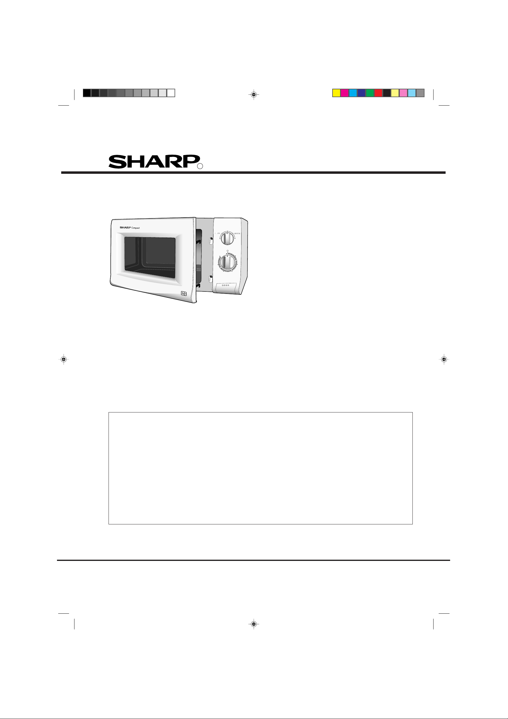
SERVICE MANUAL
COOKING CONTROL
WITH COOK & DEFROST GUIDE
MED
MED LOW
LOW
25
30
COOK & DEFROST
GUIDE (KG)
2.0
1.5
20
MED HIGH
HIGH
TIMER
0
5
0.5
10
1.0
15
MICROWAVE OVEN
S3768R210AM//
800W
E
MODEL
R-210AM
In the interests of user-safety the oven should be restored
to its original condition and only parts identical to those
specified should be used.
TABLE OF CONTENTS
Page
SERVICING....................................................................................................................................... 2
CAUTION, MICROWAVE RADIATION ............................................................................................. 3
WARNING......................................................................................................................................... 3
PRODUCT DESCRIPTION ............................................................................................................... 3
OPERATION DATA........................................................................................................................... 4
DOOR SWITCHES............................................................................................................................ 4
OUTPUT POWER TEST PROCEDURE ........................................................................................... 5
COMPONENT REPLACEMENT ....................................................................................................... 5
SCHEMATIC DIAGRAM ................................................................................................................... 7
WIRING DIAGRAM ........................................................................................................................... 8
PARTS LIST...................................................................................................................................... 9
EXPLODED ILLUSTRATION ............................................................................................................ 11
NEW FEATURE ................................................................................................................................ 14
SHARP CORPORATION
210AM - 1
Page 2

SERVICING
WARNING TO SERVICE PERSONNEL
Microwave ovens contain circuitry capable of producing very high voltage and current. Contact with following parts
will result in electrocution:High voltage capacitor, High voltage transformer, Magnetron, High voltage rectifier, High voltage harness.
REMEMBER TO CHECK 3D
1) Disconnect the supply.
2) Door opened, and wedged open.
3) Discharge high voltage capacitor.
WARNING AGAINST THE CHARGE OF THE HIGH-VOLTAGE CAPACITOR
The high-voltage capacitor remains charged about 60 seconds after the oven has been switched off. Wait for 60
seconds and then short-circuit the connection of the high-voltage capacitor (that is, of the connecting lead of the
high-voltage rectifier) against the chassis using a screwdriver with an insulated handle.
Sharp recommend that wherever possible, fault-finding is carried out with the supply disconnected. In some
cases, it may be necessary to connect the supply with the cover removed to carry out fault investigation in the
control circuitry. In such cases, the high voltage circuit should be disabled as described below to reduce the
hazards:-
• Carry out 3D checks (see above).
• Disconnect the supply leads from the high voltage transformer, making a note of the polarity. Insulate the
connectors, ensuring they are positioned away from the transformer and fastened there.
• Connect any relevant test equipment e.g. voltmeter.
• Reconnect the oven to the supply, then close the door.
• Note the results of the test, taking care to keep clear of the operational oven.
• Carry out 3D checks (see above).
• Reconnect the leads to the transformer. Take care to observe correct polarity.
• Carry out 4R checks (see below).
Microwave ovens should not be used without a load. To test for the presence of microwave energy within a cavity,
place a cup of cold water on the oven turntable, close the door and set the microwave timer for one (1) minute, set the
power level to HIGH (100%) and push the start key. When the one (1) minute has elapsed (timer at zero) carefully check
that the water is now hot.
AFTER REPAIR REMEMBER TO CHECK 4R
1) Reconnect all leads removed from components during testing.
2) Replace the outer case (cabinet).
3) Reconnect the supply.
4) Run the oven. Check all functions.
When all service work is completed, and the oven is fully assembled, the microwave power output should be checked
and microwave leakage test carried out.
IMPORTANT: If the oven becomes inoperative because of a blown fuse F8A in the 1st latch switch - monitor switch
circuit, check the 1st latch switch and monitor switch before replacing the fuse F8A.
210AM - 2
Page 3
CAUTION / WARNING
CAUTION
MICROWAVE RADIATION
Do not become exposed to radiation from the
magnetron or other parts conducting microwave energy. All input and output microwave connections,
waveguides, flanges and gaskets must be secured.
Never operate the device without a microwave energy absorbing load attached. Never look into an
open waveguide or antenna while the device is energized.
Servicing and repair work must be carried out only by
trained service engineers.
The parts marked '*' on the parts list and schematic
diagram have voltages in excess of 250V.
Removal of the outer wrap gives access to potential
above 250V.
All the parts marked "∆" on the parts list may cause
undue microwave exposure, by themselves, or when
they are damaged, loosened or removed.
WARNING
WARNING
THIS APPLIANCE MUST BE EARTHED. THE WIRES IN THIS MAINS LEAD ARE COLOURED IN
ACCORDANCE WITH THE FOLLOWING CODE:
GREEN-AND-YELLOW : EARTH BLUE : NEUTRAL BROWN : LIVE
If the mains lead is replaced, only part number QACCBA030WREO should be used
PRODUCT DESCRIPTION
SPECIFICATION
Power Requirements 230 /240 Volts 50 Hertz Single phase, 3 wire grounded
Power Consumption 1.3KW
Power Output 800 watts nominal of RF microwave energy (measured by way of IEC 705)
Operating frequency of 2450 MHz
Case Dimensions Width 449 mm Height 282 mm including foot Depth 369 mm
Cooking Cavity Dimensions Width 290 mm Height 194 mm Depth 313 mm
Turntable diameter 272 mm
Control Complement Mechanical Control System
Microwave Power for Variable Cooking
Repetition Rate :
HIGH..................... Full power throughout the cooking time
MEDIUM HIGH .....approx. 70% of Full Power
MEDIUM ...............approx. 50% of Full Power
MEDIUM LOW......approx. 30% of Full Power
LOW ..................... approx. 10% of Full Power
Set Weight Approx. 13.3 kg
210AM - 3
Page 4

OPERATING SEQUENCE
OFF CONDITION
Closing the door activates all door interlock switches (monitored latch switch and latch switch).
IMPORTANT
When the timer knob is at "0" the oven is in the OFF
condition.
HIGH, MEDIUM HIGH, MEDIUM, MEDIUM
LOW, LOW COOKING
When the microwave oven is preset for variable cooking
power, the line voltage is supplied to the power transformer
intermittently within a 32-second time base through the
relay contact which is coupled with the current-limiting relay
(RY2). The following levels of microwave power are given.
SETTING
26 sec. ON
HIGH
20 sec. ON
MEDIUM HIGH
14 sec. ON
MEDIUM
8 sec. ON
MEDIUM LOW
4 sec. ON
LOW
6 sec. OFF
12 sec. OFF
18 sec. OFF
22 sec. OFF
NOTE: The ON/OFF time ratio does not exactly correspond
to the percentage of microwave power, because
approx. 3 seconds are needed for heating up the
magnetron filament.
Approx. 100% = 800 Watts
Approx. 70% = 560 Watts
Approx. 50% = 400 Watts
Approx. 30% = 240 Watts
Approx. 10% = 80 Watts
DOOR SWITCHES
DOOR OPEN MECHANISM
LATCH HOOK
DOOR
LATCH
HEADS
DOOR OPEN BUTTON
SW1: MONITORED
LATCH SWITCH
SW3: MONITOR
SWITCH
SW2: LATCH
SWITCH
OPEN LEVER
MONITORED LATCH SWITCH (SW1)
STOP SWITCH (SW3)
1. When the oven door is closed, the contacts (COM - NO)
must be closed.
2. When the oven door is opened, the contacts (COM NO) must be opened.
MONITOR SWITCH (SW2)
1. When the oven door is closed, the contacts (COM - NC)
must be opened.
2. When the oven door is opened, the contacts (COM NC) must be closed.
3. If the oven door is opened and the contacts (COM - NO)
of the monitored latch switch (SW1) fail to open, the fuse
F8A blows simultaneously with closing the contacts
(COM - NC) of the monitor switch (SW2).
CAUTION: BEFORE REPLACING A BLOWN FUSE (F)
F8A TEST THE MONITORED LATCH SWITCH
(SW1), + MONITOR SWITCH (SW3) FOR
PROPER OPERATION.
Figure D-1. Door Open Mechanism
210AM - 4
Page 5

OUTPUT POWER TEST PROCEDURE
MICROWAVE OUTPUT POWER (IEC-705)
The power output of this oven is rated using the method specified by IEC-705. Full details of how to carry out this
procedure can be found in the Sharp Technical Training notes which is available from Sharp Parts Centre
(part number SERV-LITMW01).
Using this procedure, the heating time to raise 1000g of water by 10°C is approximately 50 seconds.
The IEC-705 procedure must be carried out using laboratory-type procedures and equipment. These requirements
make the procedure unsuitable for routing performance checks. An indication of the power being produced by the oven
can however be obtained using the procedure given below.
Alternative simplified method:
1. Place 2 litres of cold water (between 12°C and 20°C) in a suitable container.
2. Stir the water and measure the temperature in °C. Note temperature as T1.
3. Place the container in the microwave and heat the water for 2 minutes on full power.
4. When the 2 minutes is completed, remove the container and stir the water. Note the water temperature as T2.
5. Calculate the output power using the following formula:
R.F. Power Output = (T2 - T1) x 70.
Note: The result from this test should be within 10% of the power rating stated on the rating label.
MICROWAVE LEAKAGE TEST
This oven should be tested for microwave leakage on completion of any repair or adjustment, following the procedure
described in the Sharp Technical Training notes (part number SERV-LITMW01). The maximum leakage permitted in
BS EN 60335-2-25 is 50W/m
2
(equivalent to 5mW/cm2), however it is not normal to detect any significant leakage,
therefore, any leakage which is detected should be investigated.
It is essential that only leakage detectors with current calibration traceable to the National Physical Laboratories are used.
Suitable leakage detectors : CELTEC A100
APOLLO X1
COMPONENT REPLACEMENT
MONITORED LATCH SWITCH, LATCH
SWITCH, AND MONITOR SWITCH REMOVAL
1. CARRY OUT 3D CHECKS.
2. Disconnect the leads from all switches.
3. Remove the one (1) screw holding the latch hook to the
oven cavity.
4. Remove the latch hook.
5. Push the retaining tab slightly and remove the switch.
Post
LATCH HOOK
Post
SW1: MONITORED
LATCH SWITCH
Tab
SW3: MONITOR
SWITCH
210AM - 5
Tab
Post
SW2: LATCH
SWITCH
Tab
Figure C-4. Switches
Page 6

COMPONENT REPLACEMENT
DOOR REPLACEMENT
1. CARRY OUT 3D CHECKS.
2. Remove choke cover taking care not to break
clips.
3. Remove door assembly by lifting and easing
it forward.
4. On re-installation make sure the door is
parallel with the bottom line of the oven face
plate and the latch head pass through the
latch holes correctly.
5. CARRY OUT 4R CHECKS.
NOTE : After any service to the door, the
approved microwave survey meter should be
used to assure in compliance with proper
microwave radiation standards.
OUTER CASE
CABINET
DOOR ASSEMBLY
LATCH HEAD REMOVAL
1. Remove the choke as above.
2. Unhook the spring and lift the latch head clear.
3. Replacement, the reverse of the above.
FLAT TYPE
SCREW-DRIVER
PROTECT BY TAPE
CHOKE
COVER
DOOR
PANEL
LATCH HEADS
Figure C-6. Door Assembly Replacement and
Adjustment
CHOKE COVER REMOVAL
1. Insert an iron plate (thickness of about 0.5mm) or
flat type screw driver to the gap between the choke
cover and door panel as shown figure to free the
engaged part. The protect sheet may be used not
to damage the door panel.
2. Lift up the choke cover, now the coke cover is free.
INNER DOOR FILM
Removal
1. Tear the door film from the door panel.
2. Now the door film is free.
Installation
1. Tear away the backing film.
2. Put the pasted side of the door film on the door
panel.
Door film
Door film
Backing film
Backing film
Adhesive tape
Finger tab
Finger tab
OUTER DOOR FILM
Removal
1. Remove the door film from the clips on the door frame.
Installation
1. Attach the door film to the clips on the door frame.
210AM - 6
Page 7

SCHEMATIC DIAGRAM
CIRCUIT SUBJECT TO
CHANGE
WITHOUT NOTICE.
DOOR CLOSED
COOK OFF
MICROWAVE CONDITION
NOISE
FILTER
UNIT
BLU/18
EARTH
N
680K/0.5W
NOISE SUPPRESSION COIL
0.0033µ/250V
OVEN LIGHT
OL
0.22µ/250V
230/240V~50Hz
BRN/18
G-Y/18
F8A
FUSE
10M/0.5W
0.0033µ/250V
L
OVEN
THERMAL
CUT OUT
125˚C
TIMER
SWITCH
SW1
MONITORED
LATCH
SWITCH
l.
TURNTABLE MOTOR
TTM
FAN MOTOR
FM
TIMER MOTOR
TM
VARI
SWITCH
SURGE
RELAY
SURGE
RELAY
CONTACT
SURGE
RESISTOR
10/20W
SW2
LATCH
SWITCH
CAPACITOR
*
0.91µ
2100V/AC*
N.C.
POWER TRANSFORMER
*
WITH 150°C THERMOSTAT
IN PRIMARY WINDING
SW3 - MONITOR SWITCH
NOTE: INDICATES COMPONENTS
*
WITH POTENTIALS ABOVE
250V.
H.V. RECTIFIER
*
210AM - 7
MAGNETRON
*
Page 8

WIRING DIAGRAM
EARTH
ANGLE
I
Y
G
EARTH
BRN
BLU
TC:
THERMAL
L
N
CUT-OUT
125°C (OVEN)
RED
RED
LIVE
NEUTRAL
POWER
SUPPLY
CORD
NOISE
FILTER
RED
BLK
H
W
C:
H.V.
H
.
V
CAPACITOR
I
R
W
H.V. RECTIFIER
E
T:
POWER
TRANS-
FORMER
BLU
RED
MOTOR
T
H.V. WIRE B
FM: FAN MOTOR TTM: TURNTABLE
HIGH VOLTAGE COMPONENTS
BRN
GRY
MG:
MAGNETRON
FFA
BLK
PNK
ORG
GRY
BLU
OL: OVEN LAMP
BRN
ORG
YLW
NO
SW1:
MONITORED
LATCH
L
B
U
GRY
RED
B
R
N
RED
B
R
N
ORG
SWITCH
BRN
COM.
256
1
BLU
PNK
TM:
TIMER
WHT
MOTOR
NC
T
H
W
T
H
W
R2:
SURGE
Y
R
G
RESISTOR
Figure S-1. Pictorial Diagram
BLK
BLU
NO
L
B
ORG
GRY
COM.
U
BRN
NO
3
4
COM.
SW3:
BLK
MONITOR
SWITCH
BLK
R
G
BLK
Y
SW2:
LATCH
SWITCH
BRN
BRN
210AM - 8
YLW
SURGE
RELAY
NOTE: Most of the terminals are
Positive - Lock Type.
Page 9

P ART LIST
Note: The parts marked “ * ” are used in voltage more than 250V. The parts marked ∆ may cause undue microwave exposure
“§” MARK: SPARE PARTS-DELIVERY SECTION
ELECTRICAL PARTS
REF NO PART NO S DESCRIPTION Q'TY CODE
1-1 RH-DZA008WRE0 U H.V. rectifier 1 AM *
1-2 FPWBFA308WRE0 U Noise filter 1 AQ
1-3 QACCBA030WRE0 U Power supply cord 1 AQ
1-4 RV-MZA270WRE0 U Magnetron 1 BG *∆
1-5 RC-QZA218WRE0 U High voltage capacitor 1 AS *
1-6 QSW-MA110WRE0 J Monitored latch switch 2 AK
1-7 QSW-MA112WRE0 J Monitor swith 1 AN
1-8 RMOTEA339WRE1 U Fan motor 1 AU
1-9 QFS-CA024WREO U Fuse F8A 1 AC
1-10 RLMPTA066WRE0 U Oven lamp 1 AK
1-11 FMOTDA056WRKO J Turntable motor assy 1 AR
1-12 RR-WZA023WRE0 J Surge resistor 0.8 ohm 20W 1 AK
1-13 RTHM-A078URE0 U Thermal cut-out 125°C (Oven) 1 AL
1-14 RTRN-A005UREO U Power transformer 1 BH *
1-15 RRLY-A042WRE0 U Surge relay 1 AS
CABINET PARTS
REF NO PART NO S DESCRIPTION Q'TY CODE
2-1 GCABUA001URP0 U Outer case cabinet (B) 1 AT ∆
2-1 GCABUA573WRT0 U Outer case cabinet (W) 1 AT ∆
2-1 GCABUA003URP0 U Outer case cabinet (G) 1 AT ∆
2-1 GCABUA009URP0 U Outer case cabinet (GL) 1 AT ∆
2-2 GLEGPA057WRE0 U Foot 2 AB
CONTROL PANEL PARTS
REF NO PART NO S DESCRIPTION Q'TY CODE
3-1 JKNBKA004URF0 U Timer Knob (B) 1 AE
3-1 JKNBKA556WRF0 U Timer Knob (W) 1 AE
3-1 JKNBKA009URF0 U Timer Knob (G) 1 AE
3-1 JKNBKA029URF0 U Timer Knob (BL) 1 AE
3-2 JKNBKA005URF0 U Vari Knob (B) 1 AE
3-2 JKNBKA555WRF0 U Vari Knob (W) 1 AE
3-2 JKNBKA007WRF0 U Vari Knob (G) 1 AE
3-2 JKNBKA027WRF0 U Vari Knob (BL) 1 AE
3-3 HPNLCA081URR0 U Control Panel (Printed) (B) 1 AN
3-3 HPNLCA080URR0 U Control Panel (Printed) (W) 1 AN
3-3 HPNLCA082URR0 U Control Panel (Printed) (G) 1 AN
3-3 HPNLCA097URR0 U Control Panel (Printed) (BL) 1 AN
3-4 QSWTEA121WRE0 U Timer/Vari unit 1 AZ
3-5 JBTN-A001URF0 U Open button (B) 1 AE
3-5 JBTN-B009WRF0 U Open button (W) 1 AE
3-5 JBTN-A011WRF0 U Open button (G) 1 AE
3-5 JBTN-A073WRF0 U Open button (BL) 1 AE
3-6 MSPRCA045WRE0 U Open button spring 1 AA
3-7 XEPSD30P10XS0 J Screw 2 AA
ELECTRICAL PARTS
REF NO PART NO S DESCRIPTION Q'TY CODE
4-1 DOVN-A439WRT0 U Oven cavity 1 BD
4-2 LBNDKA111WRP0 U Capacitor holder 1 AD
4-3 PHOK-A092WRF4 U Latch hook 1 AH
4-4 NFANJA029WRE0 U Fan blade 1 AK
4-5 PDUC-A638WRF1 U Fan duct 1 AE
4-6 LANGFA169WRP4 U Chassis support 1 AE
4-7 PPACGA126WRE0 U Seal packing 1 AC
4-8 MLEVFA078WRF0 U Open lever 1 AE
4-9 PCOVPA309WRE0 U Waveguide cover 1 AC
4-10 PDUC-A578WRF1 U Air intake duct 1 AD
4-11 GDAI-A280WRP2 U Base plate 1 AQ
4-12 PCUSGA308WRP1 U HVT cushion 2 AA
4-13 PSPAGA001WRE0 U Vibration Proof Cushion 1 AA
210AM - 9
Page 10

PART LIST
Note: The parts marked “*” are used in voltage more than 250V. The parts marked ∆ may cause undue microwave exposure
“§” MARK: SPARE PARTS-DELIVERY SECTION
DOOR PARTS
REF NO PART NO S DESCRIPTION Q'TY CODE
5 CDORFA075URK0 U Door assembly (B) 1 AZ ∆
5 CDORFA074URK0 U Door assembly (W) 1 AZ ∆
5 CDORFA076URK0 U Door assembly (G) 1 AZ ∆
5 CDORFA077URK0 U Door assembly (BL) 1 AZ ∆
5-1 FDORFA299WRT0 U Door panel assembly 1 AU
5-2 GCOVHA366WRF0 U Choke cover 1 AG
5-3 GWAKPA085URR0 U Door frame (B) 1 AQ ∆
5-3 GWAKPA084URR0 U Door frame (W) 1 AQ ∆
5-3 GWAKPA086URR0 U Door frame (G) 1 AQ ∆
5-3 GWAKPA091URR0 U Door frame (BL) 1 AQ ∆
5-4 PSHEPA560WRE0 U Outer sealer film 1 AE
5-5 LSTPPA158WRF0 U Latch head 1 AD
5-6 MSPRTA141WRE0 U Latch spring 1 AA
5-7 PSHEPA482WRE0 U Inner Sealer film 1 AH
5-8 XEBSD30P06000 U Self tapping screw 4 AA
MISCELLANEOUS
REF NO PART NO S DESCRIPTION Q'TY CODE
6-1 FROLPA070WRK1 U Roller stay 1 AM
6-2 NTNT-A060WRE0 U Turntable 1 AN
6-3 TINS-A052URRO U Operation Manual/Cookery book 1 AM
6-4 QW-QZA191WRE0 U H.V. wire A 1 AF *
6-5 QW-QZA001URE0 U H.V. wire B 1 AE *
6-6 FW-VZA027UREO U Main wire harness 1 AT
6-7 TCAUHA001WRR1 U Caution label 1 AC
SCREW, NUT AND WASHER
REF NO PART NO S DESCRIPTION Q'TY CODE
7-1 XEPSD30P10XS0 J Self tapping screw 1 AA
7-2 XHTSD40P08RV0 J Screw 4mm x 8mm 8 AA
7-3 XCPSD30P06000 U Self tapping screw 2 AB
7-4 Not applicable to this model
7-5 XFPSD40P06000 J Screw 4mm x 8mm 1 AA
7-6 XOTSD40P12RV0 J Screw 4mm x 12mm 12 AA
7-7 XOTSE40P12000 J Screw 4mm x 12mm (Chrome) 2 AA
7-7 XOTSF40P12000 J Screw 4mm x 12mm (Black) 2 AA
7-8 LXCZA063WRE0 U HVT screw 4 AA
7-9 XHPSD40P08K00 J Screw 1 AA
7-10 LX-CZA030WRE0 J Screw 1 AA
7-11 LX-NZA026WRE0 U M4 Nyloc nut 1 AA
HOW TO ORDER REPLACEMENT PARTS
To have your order filled promptly and correctly, please furnish the following information.
1. MODEL NUMBER 2. REF. NO.
3. PART NO. 4. DESCRIPTION
210AM - 10
Page 11

CABINET AND UNIT CHASSIS PARTS
EXPLODED ILLUSTRATION
4-1
7-7
2-1
7-1
7-2
1-13
7-3
7-7
7-2
7-11
6-7
7-2
7-6
1-9
7-6
7-9
1-2
4-6
7-6
4-5
1-3
1-8
7-2
7-2
4-9
4-7
1-11
7-5
7-6
4-11
7-10
2-2
7-6
X2
7-2
NOTE: In the event of removing the
turntable motor cover this part should be
refitted using screw connection:
LX-CZA030WRE0
7-6
7-6
1-14
7-8
1-12
1-15
X4
7-6
4-12
4-13
7-6
4-8
4-4
7-6
4-3
1-4
X2
6-2
1-6
1-7
1-6
1-5
4-2
1-1
7-2
1-10
4-10
6-1
210AM - 11
Page 12

EXPLODED ILLUSTRATION
CONTROL PANEL PARTS
3-5
DOOR PARTS
3-3
3-2
3-7
3-1
3-4
3-6
5
5-4
5-8
5-5
5-6
5-2
5-7
5-1
5-3
210AM - 12
Page 13

MISCELLANEOUS
EXPLODED ILLUSTRATION
6-4
6-5
6-6
Actual wire harness may be different than illustration.
PACKING AND ACCESSORIES
ROLLER STAY
TRAY PAD
SPADPA496WRE1
DOOR PROTECTION SHEET
SPADPA531WRE0
INTO THE OVEN CAVITY (DIAGONALLY)
TURNTABLE TRAY
PACKING PAD KIT
CPADBA186WRKO
POLYETHYLENG BAG
SSAKHA047WRE0
INTO THE
OVEN CAVITY
UNDERNEATH
TRAY PACK
TRAY PAD
SPADPA496WRE1
Not replaceable items.
210AM - 13
PACKING CASE
R-2V18(W)M :SPAKCA014URR0
R-2V18(B)M :SPAKCA041URR0
Page 14

NEW FEATURE
H.V. TRANSFORMER
The H.V. Transformer has a built in self resetting thermal cut out,
which opens at 150°c ± 5°c and closes at 90°c
210AM - 14
Page 15

NOTES
210AM - 15
Page 16

R
210AM - 16
SHARP COPORATION
Printed in U.K.
 Loading...