

Page 1
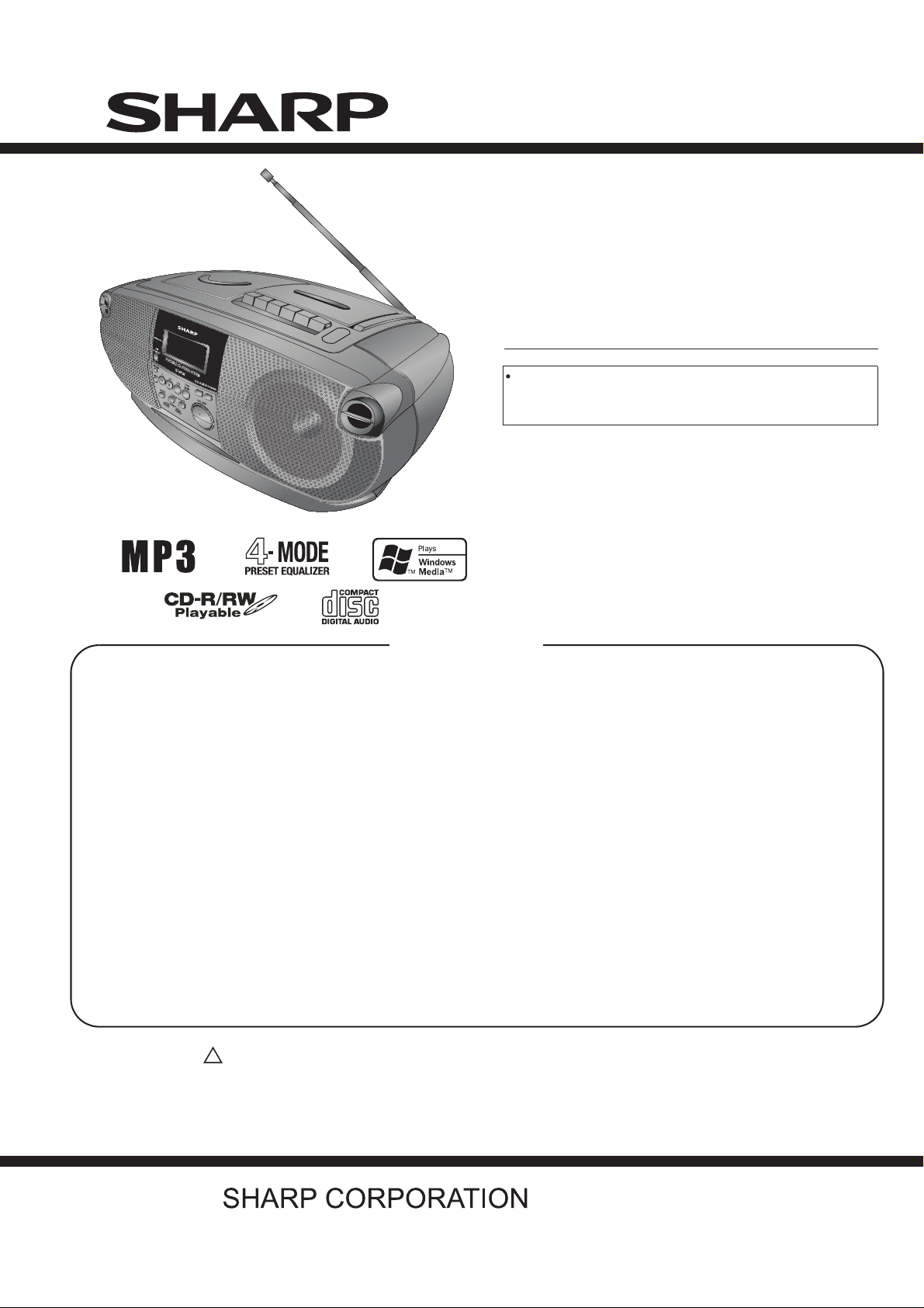
QT-MP5W
SERVICE MANUAL
No. S0623QTMP5W//
PORTABLE CD STEREO SYSTEM
CONTENTS
CHAPTER 1. GENERAL DESCRIPTION
[1] Precaution For Using Lead-Free Solder........1-1
[2] Safety Precaution For Service Manual..........1-2
[3] Voltage Selection...........................................1-2
[4] AC Power Supply Cord and AC Plug Adaptor.. 1-2
[5] Specifications ................................................1-3
[6] Names Of Parts.............................................1-4
CHAPTER 2. ADJUSTMENTS
[1] Tuner Section................................................2-1
[2] Tape Deck Adjustments.................................2-2
CHAPTER 3. DIAGRAMS
[1] Block Diagrams .............................................3-1
CHAPTER 4. CIRCUIT DESCRIPTION
[1] Waveforms Of CD Servo Circuit....................4-1
[2] Voltage..........................................................4-2
MODEL
In the Interests of user-safety the set should be restored to
its original condition and only parts identical to those
specified be used.
CHAPTER 5. CIRCUIT SCHEMATICS AND PARTS
LAYOUT
[1] Notes On Schematic Diagram .......................5-1
[2] Types Of Transistor And LED ........................5-1
[3] Schematic Diagram .......................................5-2
[4] Wiring Side Of PWB ....................................5-12
CHAPTER 6. FLOWCHART
[1] Troubleshooting.............................................6-1
CHAPTER 7. OTHERS
[1] Function Table Of IC......................................7-1
[2] LCD Display.................................................7-11
PARTS GUIDE
QT-MP5W
Parts marked with " " are important for maintaining the safety of the set. Be sure to replace these parts with specified ones
for maintaining the safety and performance of the set.
!
This document has been published to be used
for after sales service only.
The contents are subject to change without notice.
– 1
Page 2
QT-MP5W
n
CHAPTER 1.
udio
L-MP150
ervice Manual
LMP150
arket
[1] Precautions For Using Lead-Free Solder
GENERAL DESCRIPTION
.Employing lead-free solder
"AUDIO, CONTROL, RECTIFIER, SPEAKER, LED, CD, TUNER, TAPE, MCU PWB" of this model employs
lead-free solder.
The LF symbol indicates lead-free solder, and is attached on the PWB and service manuals.The alphabetical
character following LF shows the type of lead-free solder.
Example:
Indicates lead-free solder of tin,silver and copper.
2.Using lead-free wire solder
When fixing the PWB soldered with the lead-free solder, apply lead-free wire solder. Repairing with
conventional lead wire solder may cause damage or accident due to cracks.
As the melting point of lead-free solder (Sn-Ag-Cu) is higher than the lead wire solder by 40 C, were
commend you to use a dedicated soldring bit,if you are not familiar with how to obtain lead-free wire solder or
soldering bit,contact our service station or service branch in your area.
3.Soldering
As the melting point of lead-free solder (Sn-Ag-Cu) is about 220 C which is higher than the conventional lead
solder by 40 C, and as it has poor solder wettability, you may be apt to keep the soldering bit in contact with the
PWB for extended period of time. However, since the land may be peeled off or the maximum heat-resistance
temperature of parts may be exceeded, remove the bit from the PWB as soon as you confirm the steady
soldering condition.
Lead-free solder contains more tin, and the end of the soldering bit may be easily corrected. Make sure to turn o
and off the power of the bit as required.
If a different type of solder stays on the tip of the soldering bit, it is alloyed with lead-free solder.Clean the bit afte
every use of it.
When the tip of the soldering bit is blackened during use, file it with steel wool or fine sandpaper.
Be careful when replacing parts with polarity indication on the PWB silk.
Lead-free wire solder for servicing
Ref No.
PWB-A1
PWB-A2
PWB-A3
PWB-A4
PWB-A5
PWB-B
PWB-C
PWB-E 92LMP501380017
PWB-F 92LMP502300000 MCU
Parts No.
92LMP500280046
92LMP500380047
92LMP501280003
92LMP502300000
92LMP500980004
Description
AUDIO
CONTROL
RECTIFIER
SPEAKER
LED
CD
TUNER
TAPE
1 – 1
Page 3
[2] Safety Precaution For Service Manual
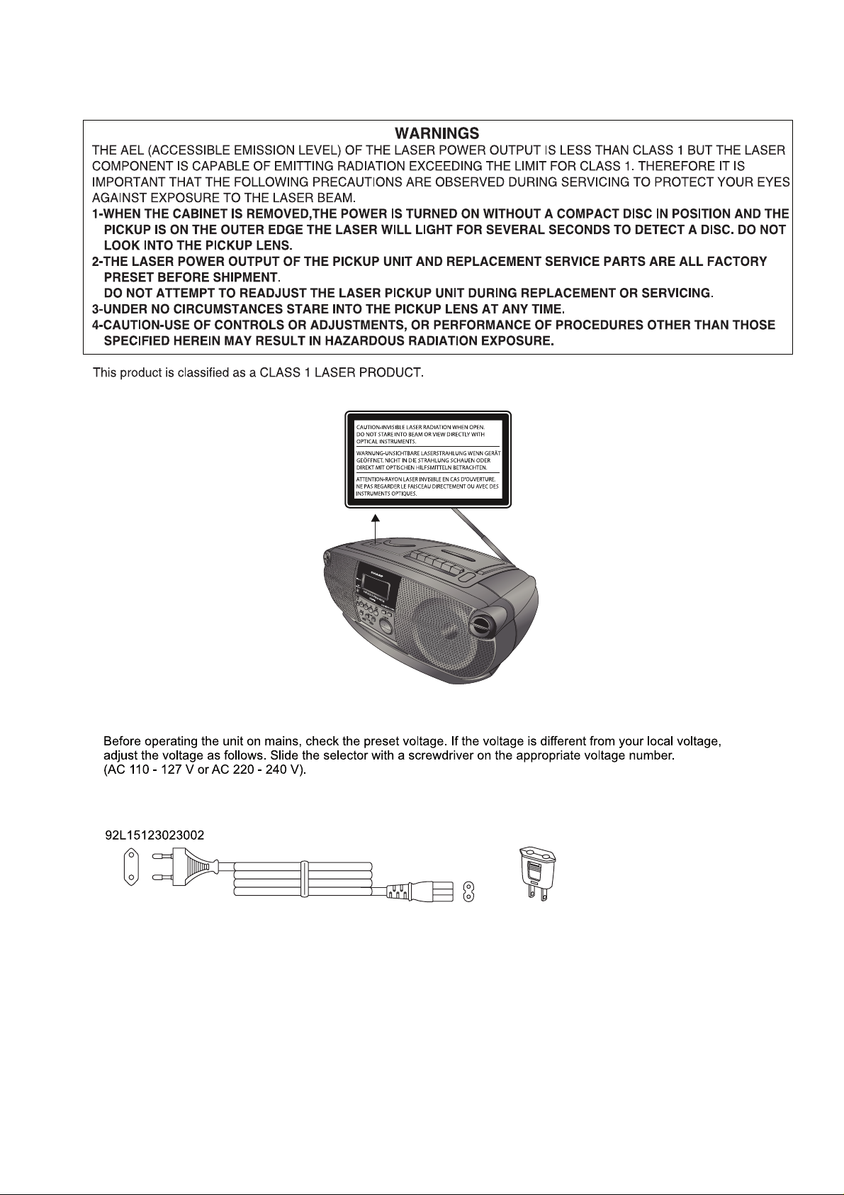
Precaution to be taken when replacing and servicing the Laser Pickup.
Laser Diode Properties
Material: AIGaAs
Wavelength: 790 nm
Emission Duration: continuous
Laser Output: max. 0.6 mW
QT-MP5W
[3] Voltage Selection
[4] AC Power Supply Cord and AC Plug Adaptor
92L15911022019
1 – 2
Page 4

QT-MP5W
[5] Specifications
FOR A COMPLETE DESCRIPTION OF THE OPERATION OF THIS UNIT, PLEASE REFER
TO THE OPERATION MANUAL.
As part of our policy of continuous improvement, SHARP reservesthe right to make design and
specification changes for productimprovement without prior notice. The performance specificationfigures
indicated are nominal values of production units. There maybe some deviations from these values in
individual units.
General
Power source AC 110 - 127/220 - 240 V, 50/60 Hz
Power
consumption
Output power MPO: 5.4 W (2.7 W + 2.7 W)
Speaker type 2 way speaker system
Dimensions Width: 410 mm (16-1/4")
Weight 3.4 kg (7.5 lbs.) without battery
DC12V [“D” size (UM/SUM-1, R20 or HP-2)
battery x 8]
Power on: 15 W
(AC OPERATION, 10% T.H.D)
RMS: 4 W (2 W + 2 W)
(DC OPERATION, 10% T.H.D)
10 cm (4") - 8 ohms x 2 - Speaker
4 cm (1 - 3/5") - 8 ohms x 2 - Tweeter
Height: 165 mm (6-1/2")
Depth: 240 mm (9-1/2")
Radio
Frequency range FM: 88.0 - 108.0 MHz
AM: 531 - 1602 kHz
Tape recorder
Frequency response 80 - 8000 Hz (Normal tape)
Signal/noise ratio 40 dB
Wow and flutter 0.3% (WRMS)
Motor DC 9 V electric governor
Bias system AC bias
Erase system Magnet erase
CD player
Type Compact disc player
Signal readout Non-contact, 3-beam semiconductor laser
D/A converter 1-bit D/A converter
Frequency
response
pickup
60 - 20,000 Hz
1 – 3
Page 5
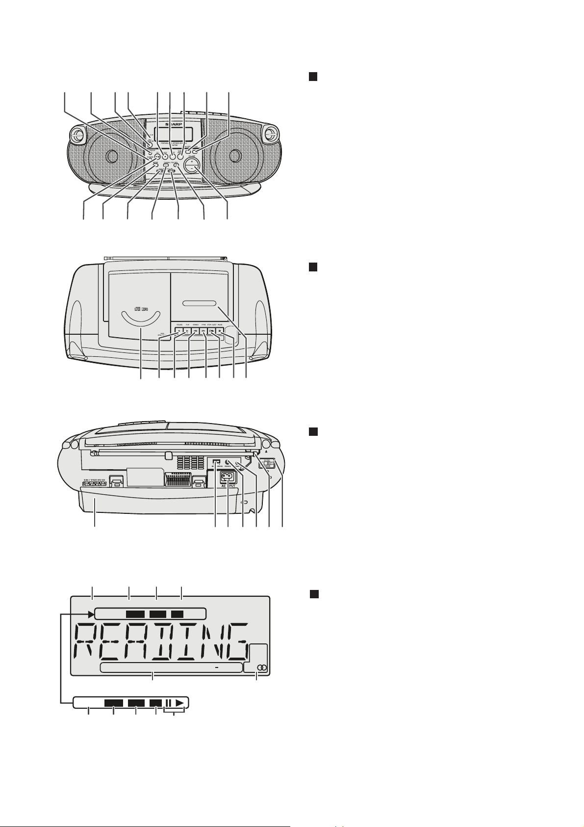
[6] Names Of Parts
QT-MP5W
1234 56789
10 11 12 13 14 15 16
Front panel
1.Random Button
2.Memory/Display Button
3.On/Stand-by Button
4.Stand-by Indicator
5.CD Stop Button
6.Tape Button
7.Tuner (Band) Button
8.Equaliser Button
9.Extra Bass Button
10.CD Play/Pause Button
11.CD Repeat Button
12.Fast Reverse/Track Down/Tuner Preset Down Button
13.Tuner Tuning Down/Folder Down Button
14.Fast Forward/Track Up/Tuner Preset Up Button
15.Tuner Tuning Up/Folder Up Button
16.Volume Up and Down Button
Top panel
1.CD Compartment
2.Tape Record Button
3.Tape Play Button
4.Tape Rewind Button
5.Tape Fast Forward Button
6.Tape Stop/Eject Button
7.Tape Pause Button
8.Cassette Compartment
1
1
MEMORY
TRACK
243
FOLDER 1P RANDOM
TRACK
WMA MP3
ROCK CLASSIC POPS JAZZ
WMA MP3
324567
CD
E
10
CD
8
2
314 567
kHz
MHz
X BASS ST
11
Back panel
1.Battery Compartment
2.Beat Cancel Selector
3.AC Input Socket
4.Headphone Socket
5.Reset Switch
6.FM/AM Aerial
7.Voltage selector
Display
1.Memory Indicator
2.Folder Indicator
3.Repeat mode Indicator
4.Random Indicator
5.Track Indicator
6.WMA Indicator
7.MP3 Indicator
8.CD Indicator
9.Disc Play/Pause Indicator
10.Equaliser modes Indicators
11.Tuner Stereo Indicator
56789
1 – 4
Page 6
QT-MP5W
CHAPTER 2. ADJUSTMENTS
[1] Tuner Adjustments
Use a plastic screw driver for adjustments.
Adjust the intermediate frequency of AM to the frequency of ceramic filter.
Set of unit
Supply voltage : DC 12V
Speaker impedance : 8 ohms
Standard output : 50 mW
Function select : TUNER
R144
Parts Location:
L101
CT101
C129
L102
R125
a. AM adjustment Band: AM
Step
Adjusting
Circuit
1IF
Close the output
terminal by sweep
generator, it place to
AM ANT
Connections
Input Output
Connect VTVM to
C129(-)
SG
Frequency
450 KHz 520 KHz T103
Position of
Tuning Dial
Adjustment
CT102
T102
T101
T103
VTVM
Oscilloscope
Tuning cover
2
3 Tracking
range
Connect AM SG to
test loop
Connect AM SG to
test loop
Connect VTVM to
R144
Connect VTVM to
speaker terminals
520 KHz 520 KHz T101 VT: 1.0+-/0.05V
1710 KHz 1710 KHz VT: 7.2+-/0.5V
600 KHz 600 KHz T102
1400 KHz 1400 KHz TC102
b. FM adjustment Band: FM FM Dummy antenna: 75 ohms unbalance
Step
Adjusting
Circuit
1IF
Tuning cover
2
3 Tracking
range
Connect sweep
generator to C139
Connect FM SG to
D102(+) & D101(-)
Connect FM SG to
D102(+) & D101(-)
Connections
Input Output
Connect VTVM to
C129(-)
Connect VTVM to
R125
Connect VTVM to
speaker terminals
SG
Frequency
10.7 MHz 90.00 MHz
87.90 MHz 87.90 MHz L102 VT: 1.8+-/0.1V
107.90 MHz 107.90 MHz VT: 7.0+-/0.5V
90.00 MHz 90.00 MHz L101
106.00 MHz 106.00 MHz TC101
Position of
Tuning Dial
Adjustment
2 – 1
Max.
VTVM
Oscilloscope
Max.
Page 7
[2] Tape Deck Adjustments
1. HEAD REPLACEMNET
After replacement, demagnetize the heads by using a degausser.
Be sure to clean the heads before attempting to make any adjustments.
All wiring should be returned to the original position after work is completed.
2. HEAD AZIMUTH ADJUSTMENT
(1) Load the test tape (STT-113CN, etc., 8 KHz) for azimuth adjustment.
(2) Press the PLAY button.
(3) Use a cross-tip screwdriver to turn the screw for azimuth adjustment
so that left and right output are maximized.
(4) Press the STOP button.
(5) After completion of the adjustment, use thread lock (TB-1401B)
to secure azimuth-adjustment screw.
3. MOTOR REPLACEMENT
4. AC BIAS FREQUENCY ADJUSTMENTS
(1) Connect counter to T801 (BS).
(2) R/P switch in recording state.
(3) Adjusting T801 use a plastic screw, AC bias frequency: 80 KHz.
QT-MP5W
5. MOTOR SPEED ADJUSTMENT
(1) Insert the test tape (MTT-1 11N, etc., 3,000 Hz).
(2) Press the PLAY button.
(3) Use a flat-tip screwdriver to turn the SVR (located inside
the rear of the motor) to adjust SVR so that the frequency
counter become 3,000 Hz.
6. CHECKING THE MECHANISM TORQUSE AND TENSION
Measurement Take-up Torque Back Tension Tape Tension
Cassette of measurement
PLAY 30 - 70 gf.cm 1.5 - 5 gf.cm 70 gf or more
F.FWD 55 gf or more ------ ------
REW 55 gf or more ------ ------
PLAY: TW-2111A
F.FWD/REW: TW-2231
PLAY: TW-2111A
Drive-power cassette
TW-2412
2 – 2
Page 8
QT-MP5W
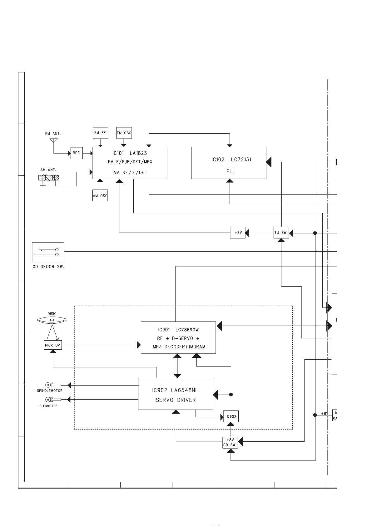
CHAPTER 3. BLOCK DIAGRAM
A
B
C
D
E
F
G
H
1
23456
Figure 1: BLOCK DIAGRAM (1/2)
3 – 1
Page 9
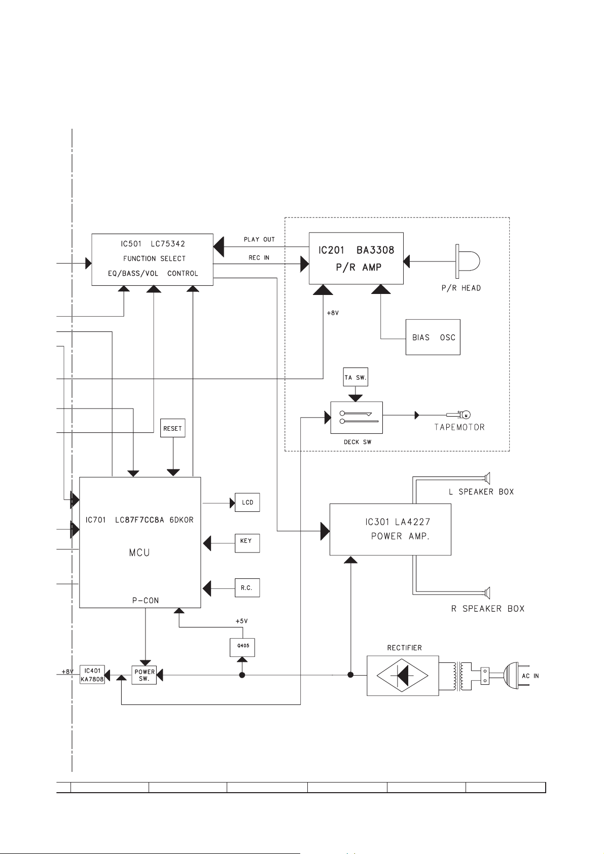
QT-MP5W
7
8 9 10 11 12
Figure 2: BLOCK DIAGRAM (2/2)
3 – 2
Page 10
QT-MP5W
CHAPTER 4.
CIRCUIT DESCRIPTION
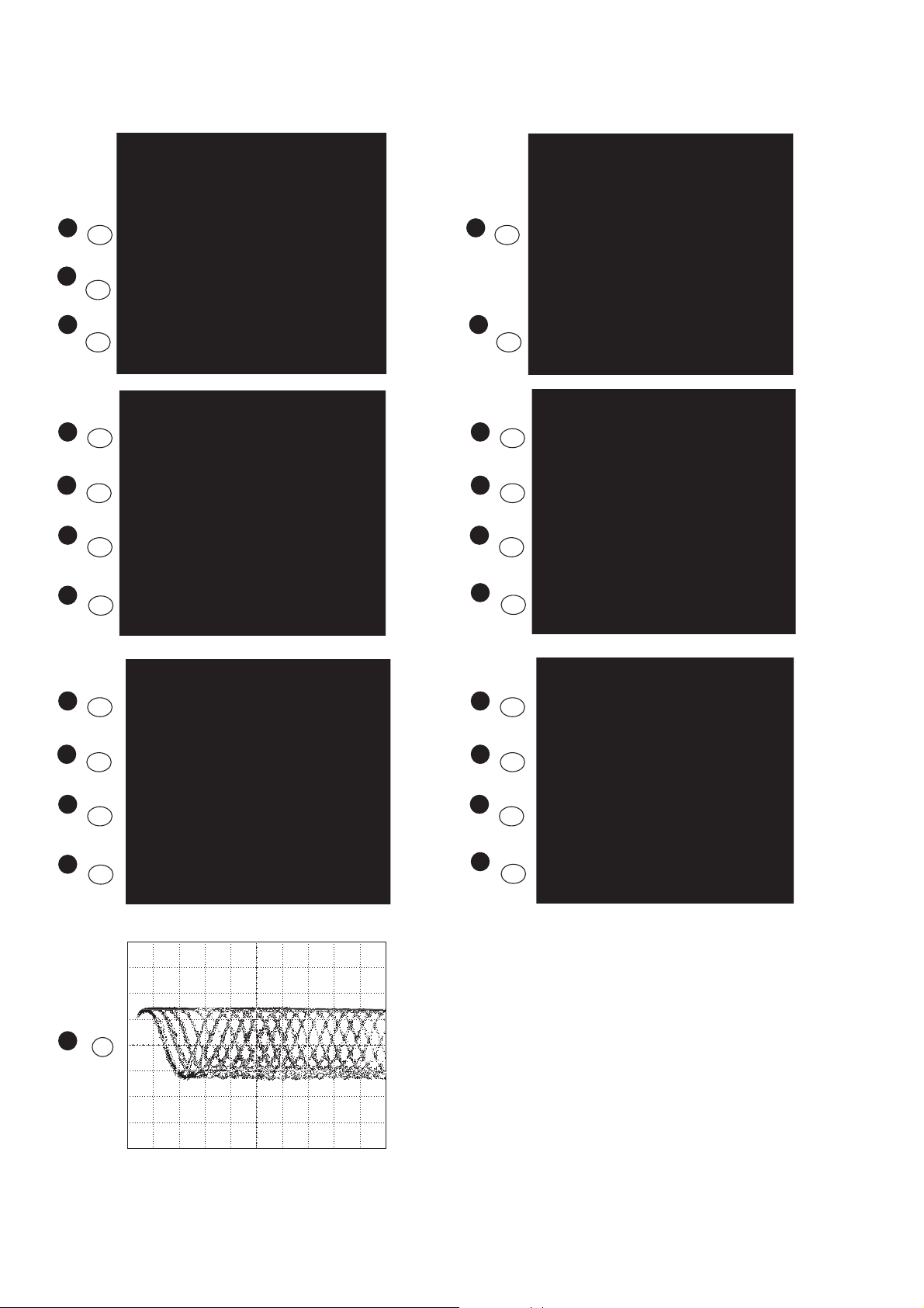
[1] Waveform Of Servo Circuit
1
21
IC901
2
72
IC901
3
47
IC901
4
22
IC901
6
23
IC901
4
IC901
5
IC901
4
IC901
6
IC901
22
18
22
23
7
IC901
8
IC901
4
IC901
6
IC901
7
IC901
8
IC901
23
24
25
22
24
25
7
IC901
8
IC901
4
IC901
6
IC901
7
IC901
8
IC901
24
25
22
23
24
25
9
IC901
2
Vp-p=1.0 V~1.3 V
0.5 mV/div,0.5 µsec/div
4 – 1
Page 11
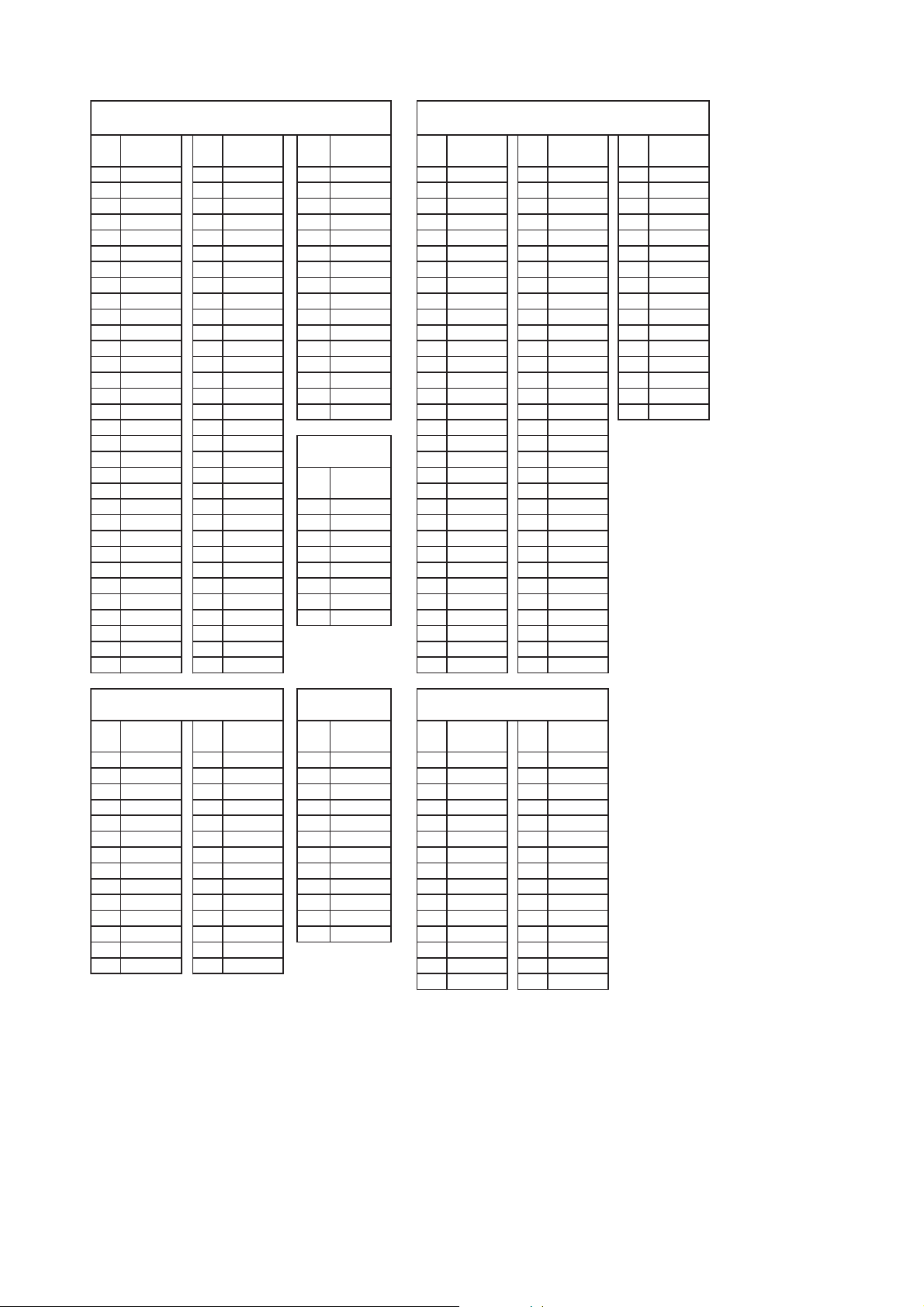
[2] Voltage
QT-MP5W
IC901
LC78690W
PIN PIN PIN PIN PIN PIN
NO NO NO NO NO NO
1 1.63 33 0.00 65 0.00 1 0.70 33 2.40 65 4.65
2 1.60 34 0.00 66 1.81 2 1.30 34 2.40 66 0.00
3 1.66 35 0.00 67 0.00 3 1.10 35 2.40 67 4.80
4 1.72 36 3.30 68 3.30 4 0.00 36 2.40 68 0.00
5 1.70 37 0.00 69 0.00 5 4.80 37 2.40 69 0.00
6 1.70 38 1.80 70 0.00 6 2.20 38 2.40 70 1.70
7 1.70 39 3.30 71 0.00 7 2.30 39 4.80 71 0.00
8 1.70 40 0.00 72 1.39 8 0.00 40 0.00 72 0.00
9 1.70 41 3.30 73 1.39 9 2.26 41 2.40 73 0.00
10 1.70 42 0.00 74 3.20 10 2.30 42 2.40 74 3.10
11 1.70 43 0.00 75 1.56 11 4.80 43 2.40 75 0.00
12 0.00 44 3.00 76 3.10 12 1.50 44 2.40 76 0.00
13 1.70 45 4.47 77 0.00 13 4.80 45 2.40 77 4.80
14 1.70 46 3.27 78 1.56 14 1.76 46 2.40 78 3.26
15 1.67 47 2.95 79 3.20 15 4.80 47 2.40 79 4.74
16 1.60 48 3.30 80 1.62 16 4.80 48 2.40 80 4.82
IC201
BA3308
20 0.00 52 0.00 PIN 20 1.96 52 2.40
21 3.30 53 0.00 NO 21 4.83 53 2.40
22 1.66 54 0.00 1 1.80 22 0.00 54 2.40
23 1.67 55 0.00 2 0.00 23 0.90 55 2.40
24 1.67 56 0.00 3 1.90 24 2.40 56 2.40
25 1.67 57 0.00 4 0.00 25 2.40 57 2.40
26 0.00 58 0.00 5 7.60 26 2.40 58 1.05
27 0.00 59 0.00 6 1.89 27 2.40 59 4.79
28 1.19 60 0.00 7 0.00 28 2.40 60 4.79
29 1.10 61 3.24 8 1.87 29 2.40 61 2.40
.12603.303
EGATLOVEGATLOV VOLTAGE
VOLTAGE
VOLTAGE
IC701
LC87F7CC8A
VOLTAGE VOLTAGE
04.29408.47103.39406.171
04.20500.08100.00503.381
04.21508.49100.01500.091
04.22604.20365
04.23604.21358.13600.013
04.24604.22398.14691.223
IC902
LA6548
PIN PIN PIN
VOLTAGE VOLTAGE
NO NO NO NO NO
1 7.92 15 3.31 1 12.25 1 0.65 16 0.00
2 0.00 16 3.93 2 6.10 2 0.15 17 3.17
3 1.66 17 1.66 3 11.30 3 0.00 18 3.17
4 1.66 18 1.66 4 1.21 4 0.00 19 3.16
5 3.63 19 3.63 5 0.00 5 3.10 20 3.17
6 3.63 20 3.63 6 12.00 6 3.10 21 3.10
7 0.00 21 0.00 7 0.00 7 3.17 22 3.16
8 0.00 22 0.00 8 0.00 8 3.17 23 3.17
9 3.63 23 3.63 9 1.21 9 3.17 24 3.17
10 3.63 24 3.63 10 11.30 10 3.10 25 3.10
11 1.67 25 1.67 11 6.30 11 3.17 26 3.10
12 1.66 26 1.67 12 13.00 12 3.17 27 0.00
LA4227
VOLTAGE
PIN PIN
VOLTAGE
15 0.00
105CI103CI
LC75342M
VOLTAGE
1.34129.78232.741
30 0.63
01.38271.33106.17203.331
63.6927
4 – 2
Page 12
QT-MP5W
CHAPTER 5. CIRCUIT SCHEMATICS AND PARTS LAYOUT
[1] Notes On Schematic Diagram
•Resistor:
To differentiate the units of resistors, such symbol as
K and M are used: the symbol K means 1000 ohm
and the symbol M means 1000 kohm and the
resistor without any symbol is ohm-type resistor.
Besides, the one with “Fusible” is a fuse type.
• Capacitor:
To indicate the unit of capacitor, a symbol P is used:
this symbol P means pico-farad and the unit of the
capacitor without such a symbol is microfarad. As to
electrolytic capacitor, the expression “capacitance/
withstand voltage” is used.
(CH), (TH), (RH), (UJ): Temperature compensation
(ML): Mylar type
(P.P.): Polypropylene type
• Schematic diagram and Wiring Side of P.W.Board
for this model are subject to change for
improvement without prior notice.
• The indicated voltage in each section is the one
measured by Digital Multimeter between such a
section and the chassis with no signal given.
1. In the tuner section,
indicates AM
indicates FM stereo
2. In the audio section, a tape is being played back.
3. In the deck section, a tape is being played back.
( ) indicates the record state.
4. In the rectifier section, a tape is being played
back.
5. In the CD section, the CD is stopped.
• Parts marked with “ “ ( ) are
important for maintaining the safety of the set. Be
sure to replace these parts with specified ones for
maintaining the safety and performance of the set.
REF. NO DESCRIPTION POSITION
SW701 Power On / Stand-by ON—OFF
SW702 Fast Reverse / Track Down /
Tuner Preset Down
SW703 Equaliser ON—OFF
SW704 Extra Bass ON—OFF
SW705 USB Play / Pause ON—OFF
SW706 CD Play / Pause ON—OFF
SW707 Tuner (Band) ON—OFF
SW708 Tape ON—OFF
SW709 Volume Up ON—OFF
ON—OFF
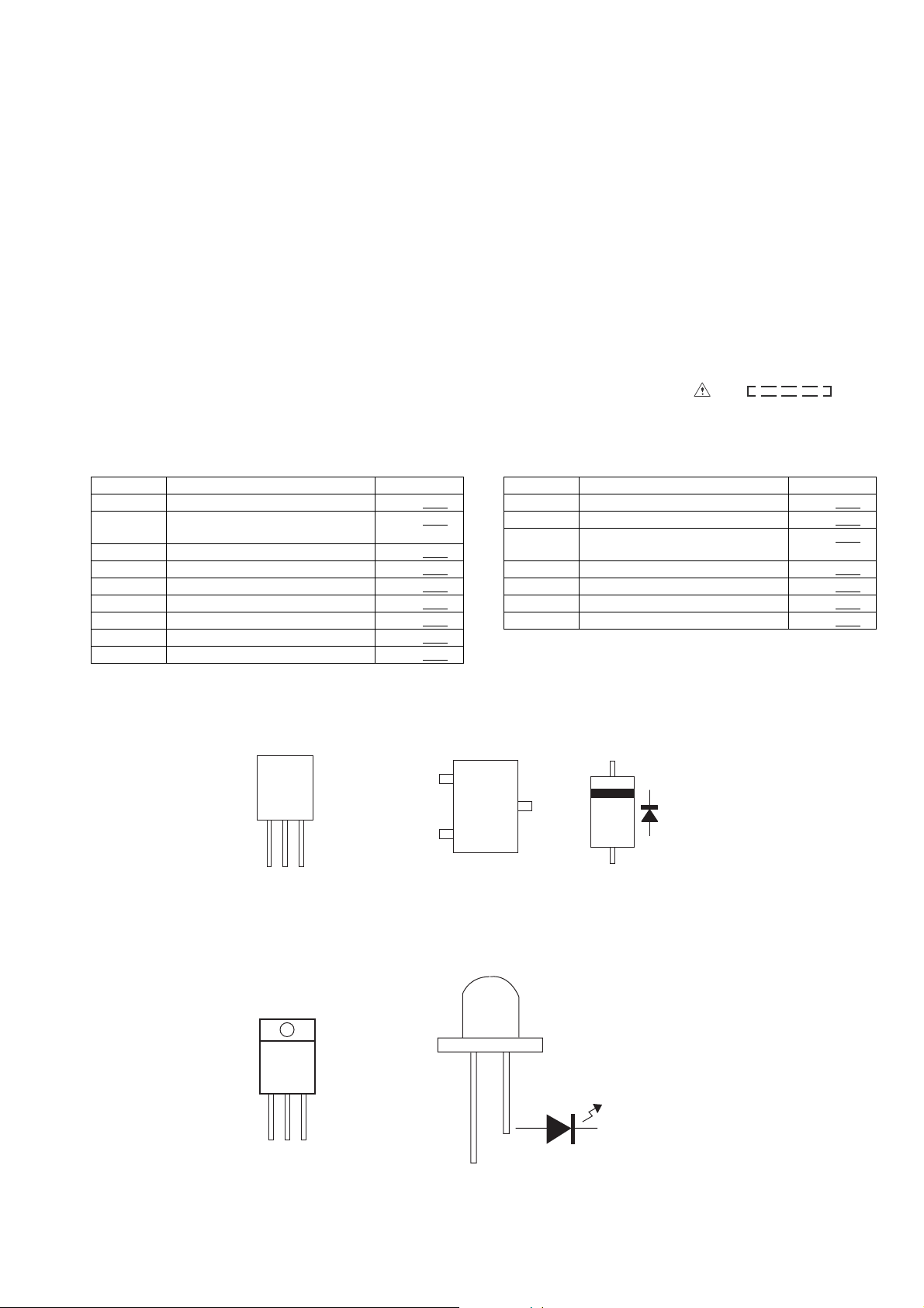
[2] Types Of Transistor And LED
FRONT
VIEW
E C B
(S)(G)(D)
(1)(2)(3)
(3)
(1)
A928A
9014C
S8550
S8050
9015C
REF. NO DESCRIPTION POSITION
SW710 Stop ON—OFF
SW711 Repeat / Random ON—OFF
SW712 Fast Forward / Track Up /
SW713 Tuner Tuning Down / Folder Down ON—OFF
SW714 Tuner Tuning Up / Folder Up ON—OFF
SW715 Volume Down ON—OFF
SW716 Memory Display ON—OFF
B
TOP
VIEW
E
(2)
HY3C
HY4C
Tuner Preset Up
TOP VIEW
C
1N4001
1N4148
ON—OFF
FRONT
VIEW
E C B
CW7809
B1185
B772
FRONT
VIEW
92L22708030000
92L22708050012
5 – 1
Page 13
QT-MP5W
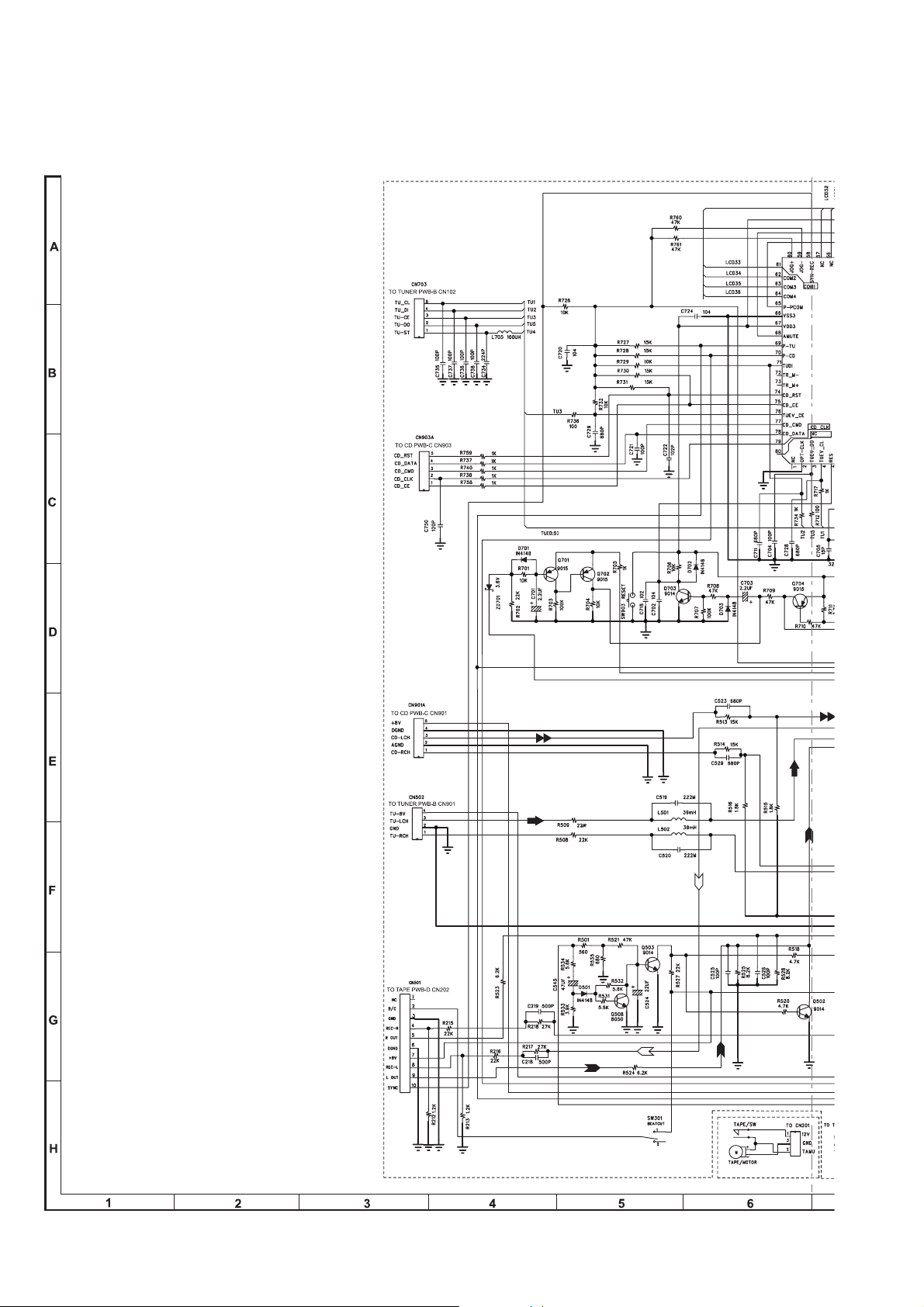
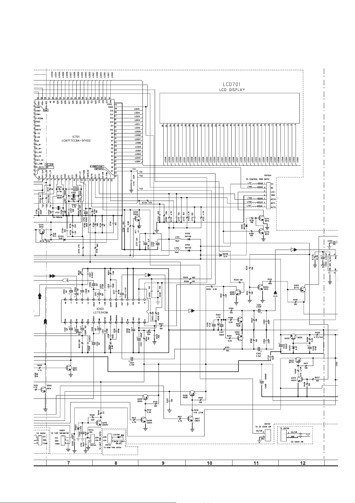
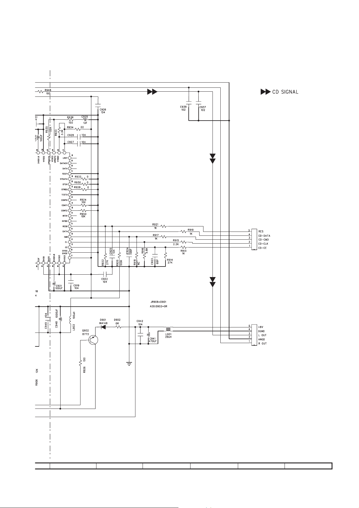
[3] Schematic Diagram
Figure 5-1: AUDIO SCHEMATIC DIAGRAM (1/3)
5 – 2
Page 14
QT-MP5W
B
LED PWB-A4
Figure 5-2: AUDIO SCHEMATIC DIAGRAM (2/3)
5 – 3
AUDIO PW
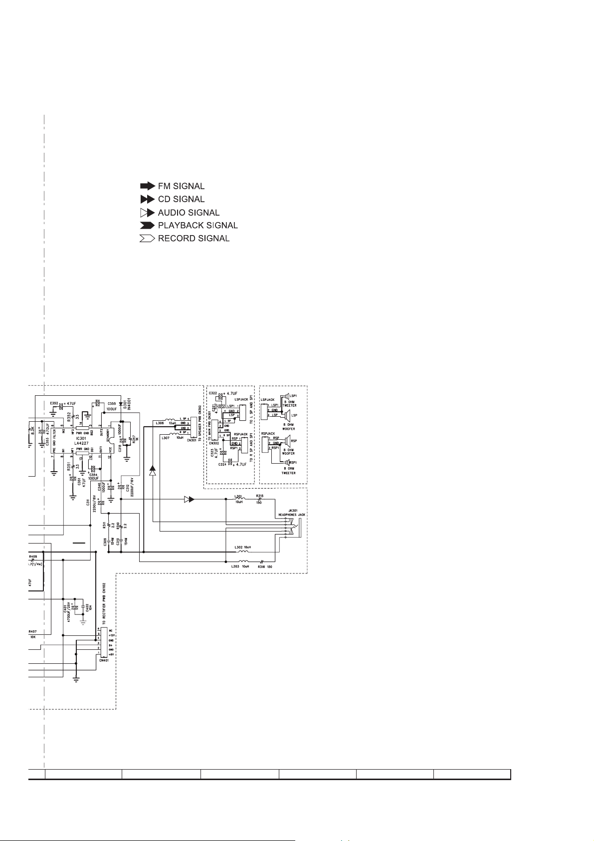
Page 15
QT-MP5W
IO PWB-A1
SPEAKER
PWB-E
13 14 15 16 17 18
Figure 5-3: AUDIO SCHEMATIC DIAGRAM (3/3)
5 – 4
Page 16
QT-MP5W
A
B
C
D
E
F
G
H
1
23456
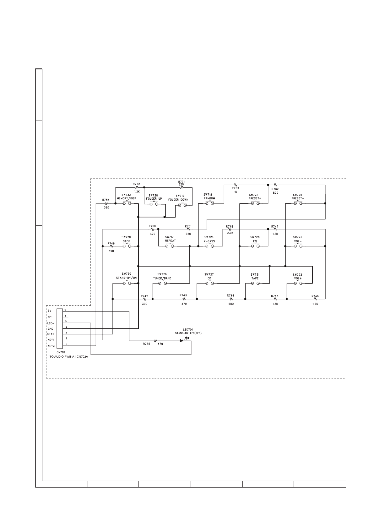
Figure 5-4: CONTROL SCHEMATIC DIAGRAM
5 – 5
Page 17
QT-MP5W
A
B
C
D
PT1
AC SOCKET
E
F
G
(VS1)
AC SUPPLY
110-127 / 220-240V
50 / 60Hz
H
1
23456
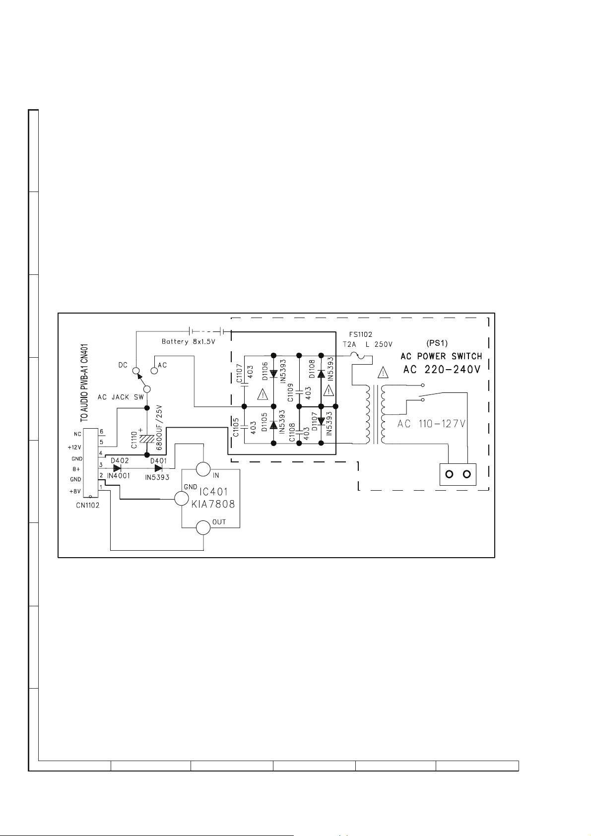
Figure 5-5: RECTIFIER SCHEMATIC DIAGRAM
5 – 6
Page 18

-MEMO-
QT-MP5W
5 – 7
Page 19

QT-MP5W
A
B
C
CN902
TO DA11MMV
IC901
LC78690W
D
E
SW901
Limit Switch
F
G
H
1
23456
Figure 5-6: CD SCHEMATIC DIAGRAM (1/2)
5 – 8
Page 20
QT-MP5W
CN903
TO MAIN PWB CN903A
CN901
TO MAIN PWB CN901A
7
8 9 10 11 12
Figure 5-7: CD SCHEMATIC DIAGRAM (1/2)
5 – 9
Page 21
QT-MP5W
A
B
C
D
E
F
G
H
1
23456
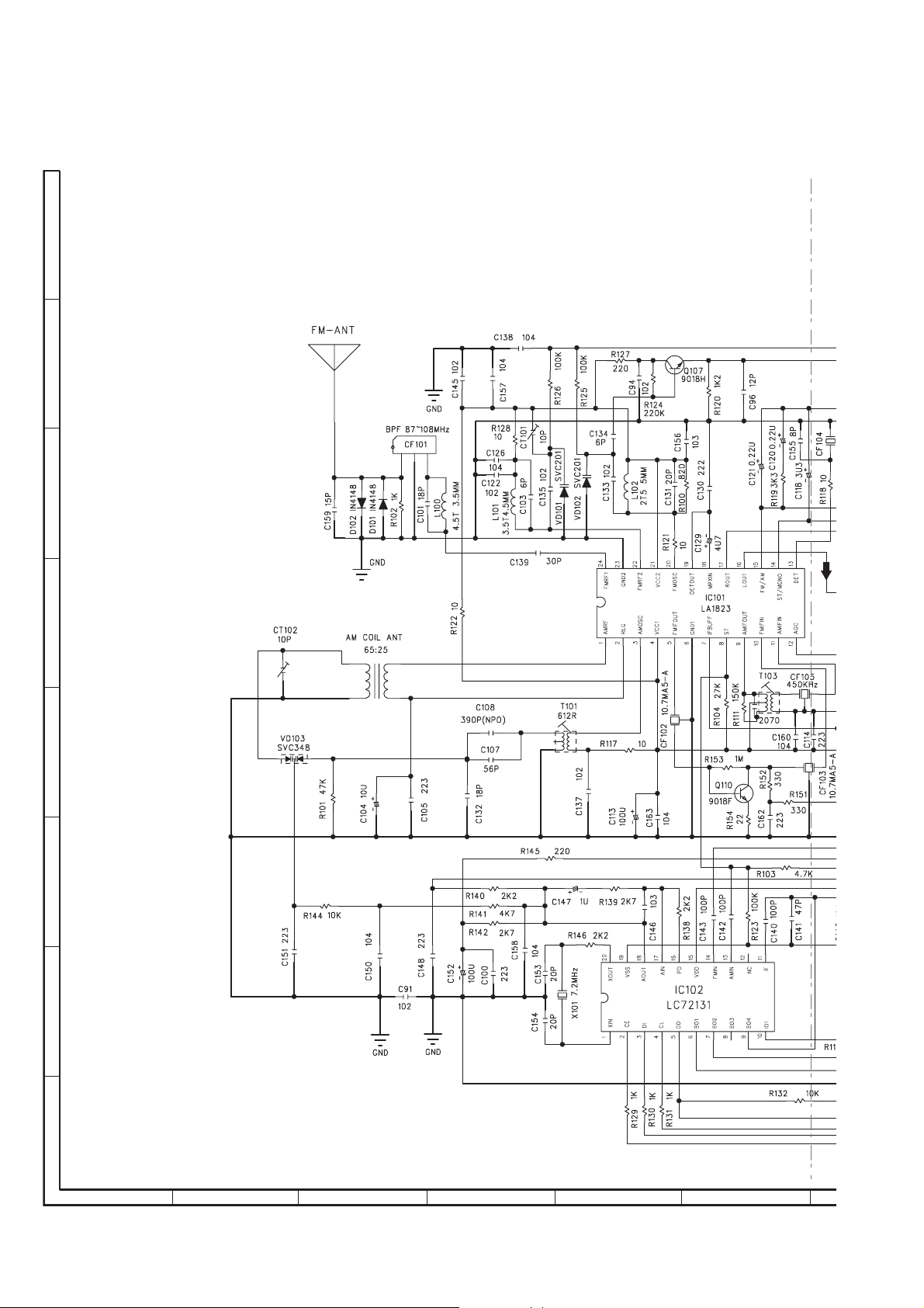
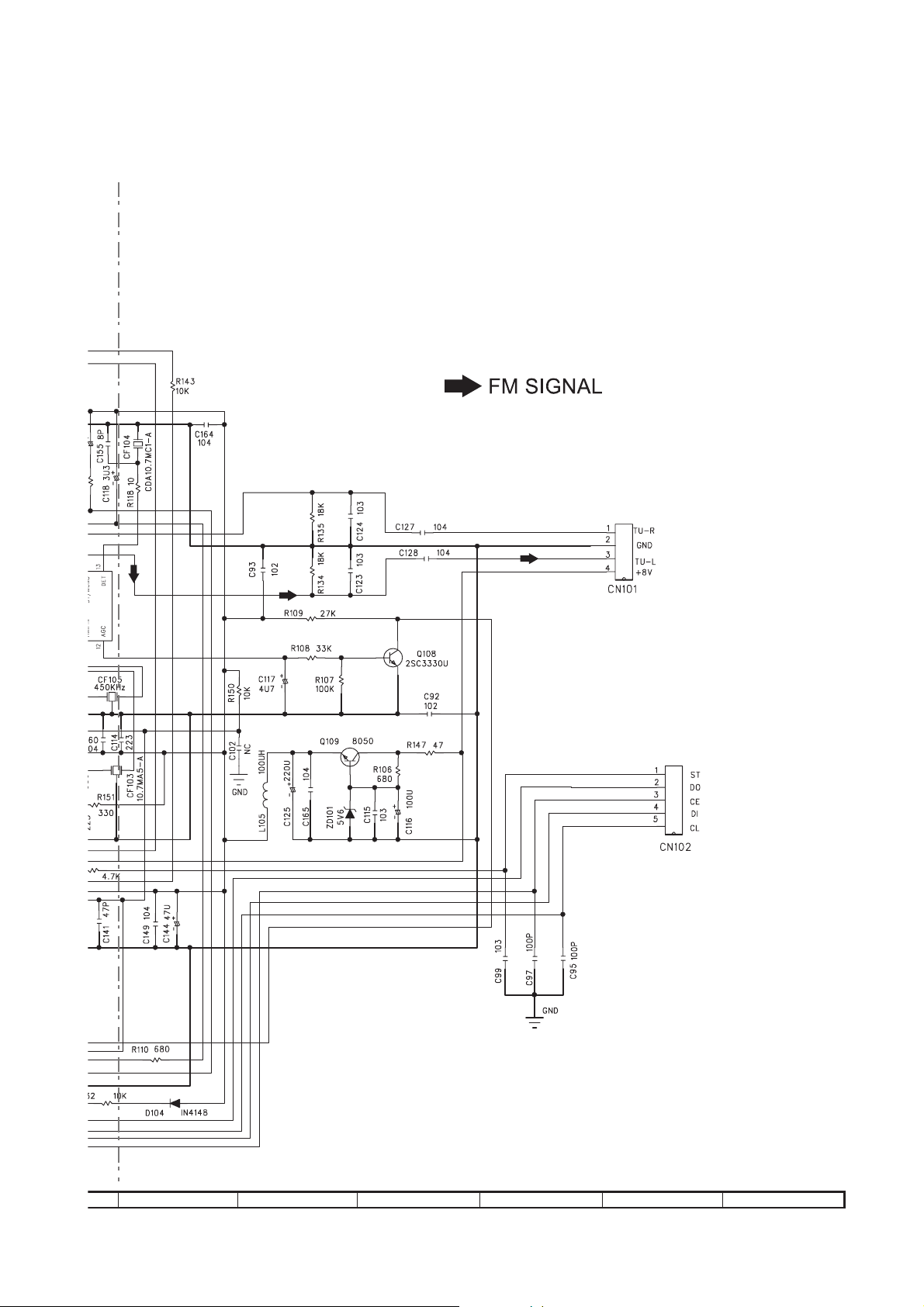
Figure 5-8: TUNER SCHEMATIC DIAGRAM (1/2)
5 – 10
Page 22
TO AUDIO PWB-A1
CN502
QT-MP5W
TO AUDIO PWB-A1
CN703
7
8 9 10 11 12
Figure 5-9: TUNER SCHEMATIC DIAGRAM (2/2)
5 – 11
Page 23

QT-MP5W
A
B
C
D
E
F
G
H
1
23456
Figure 5-10: TAPE SCHEMATIC DIAGRAM (1/2)
5 – 12
Page 24

QT-MP5W
7
8 9 10 11 12
Figure 5-11: TAPE SCHEMATIC DIAGRAM (2/2)
5 – 13
Page 25

QT-MP5W
[4] Wiring Side Of PWB
AUDIO PWB-A1
BCE
ORBKBKBKBK
12345
12345
ECB
ECB
BCE
20 2122 23 24 25 26 27 28 29 30 31 32 33 34 35 36
19
15 16 17 18
14
10 11 12 13
123456789
1234567
12
BCE
ECB
BCE
BCE
BC
ECB
ECB
CE
B
BCE
34567
BCE
21
2
1
RD
WH
CN706
TO
LED PWB-A4
Figure 5-12: WIRING SIDE OF AUDIO PWB (TOP VIEW) (1/2)
5 – 14
1
2345
RDGYGYGYGY
GY
Page 26

ECB
TO
SPEAKER
432
1
GYGYGY
RD
4321
WB BW
QT-MP5W
LED PWB-A4
21
BC
BCE
ECB
CE
BCE
BCE
BCE
BCE
1
ORBKBK
BK
BK
12345
BCE
ECB
ECB
OR
GY
GY
BCE
GY
GY
54321
ECB
B
C401
BCE
BK
12
12
BK
TO
CD DOOR
123
BCE
BCE
1
2345
GY
GYGYGY
BR
1
234
ORGYGY
BCE
BCE
10 9 8 7 6 5 4 3 2 1
GY
10 9 8 7 6 5 4 3 2 1
CNS501
Figure 5-13: WIRING SIDE OF AUDIO PWB (TOP VIEW) (2/2)
5 – 15
Page 27

QT-MP5W
AUDIO PWB-A1
Figure 5-14: WIRING SIDE OF AUDIO PWB (BOTTOM VIEW) (1/2)
5 – 16
Page 28

QT-MP5W
Figure 5-15: WIRING SIDE OF AUDIO PWB (BOTTOM VIEW) (2/2)
5 – 17
Page 29

QT-MP5W
TUNER PWB-B
1111
12345
RA1
BR1
CB
E
BR2
BRRDBKGR
BAR ANTENNA
Figure 5-16: WIRING SIDE OF TUNER PWB (TOP VIEW)
5 – 18
Page 30

ROD ANTENNA
QT-MP5W
BR
Figure 5-17: WIRING SIDE OF TUNER PWB (TOP VIEW)
5 – 19
Page 31

QT-MP5W
A
B
C
D
E
F
G
H
1
2 3 4 5 6
TUNER PWB-C
Figure 5-18: WIRING SIDE OF TUNER PWB (BOTTOM VIEW)
5 – 20
Page 32

QT-MP5W
A
B
C
D
E
F
G
H
1
2 3 4 5 6
RECTIFIER PWB-A3
OR
GY
TO
CN401
MAIN PWB-A1
GY
GY
GY
5 4 3 21
5 4 3 21
Figure 5-19: WIRING SIDE OF RECTIFIER PWB
5 – 21
Page 33

A
B
C
D
E
F
G
H
1
2 3 4 5 6
QT-MP5W
RD
WH
YL
BK
RD
RD BR
BK
BR
BL
RD
YL
Figure 5-20: WIRING SIDE OF RECTIFIER PWB
5 – 22
Page 34

-MEMO-
QT-MP5W
5 – 23
Page 35

QT-MP5W
CONTROL PWB-A2
GY
7
GY
GY
GY
GY
GY
OR
123456
1234567
Figure 5-21: WIRING SIDE OF CONTROL PWB (1/2)
5 – 24
Page 36

QT-MP5W
Figure 5-22: WIRING SIDE OF CONTROL PWB (2/2)
5 – 25
Page 37

A
B
C
D
E
F
G
H
1
2 3 4 5 6
QT-MP5W
CD PWB-B
TO
AUDIO PWB-A1
CN901-A
GYGYGYGYOR
12345
12345
CNS901-A
BCE
13579111315
246810121416
BCE
BK
BK
TO
CN903-A
BK
BK
OR
12345
12345 1234
CN903
MAIN PWB-A1
COLOR TABLE
CNS903-A
BK BLACK
GY GRAY
OR ORANGE
Figure 5-23: WIRING SIDE OF CD SERVO PWB (TOP VIEW)
5 – 26
Page 38

QT-MP5W
A
B
C
D
E
F
G
H
1
2 3 4 5 6
CD PWB-B
Figure 5-24: WIRING SIDE OF CD SERVO PWB (BOTTOM VIEW)
5 – 27
Page 39

QT-MP5W
TAPE PWB-E
CNS202-B
OR
123456789
CNS202-A
123456789
202NC
123456789
GY
GY
1A-BWP OIDUA
403NC
OT
GY
GY
GY
GY
GY
GY
10
GY
10
10
Figure 5-25: WIRING SIDE OF TAPE PWB (TOP VIEW) (1/2)
5 – 28
Page 40

QT-MP5W
EBC
Figure 5-26: WIRING SIDE OF TAPE PWB (TOP VIEW) (2/2)
5 – 29
Page 41

QT-MP5W
TAPE PWB-E
Figure 5-27: WIRING SIDE OF TAPE PWB (BOTTOM VIEW) (1/2)
5 – 30
Page 42

QT-MP5W
Figure 5-28: WIRING SIDE OF TAPE PWB (BOTTOM VIEW) (1/2)
5 – 31
Page 43

QT-MP5W
SPEAKER PWB-E
TO
AUDIO PWB-A1
CN301
L-SP JACK
TO
RIGHT SPEAKER
123
CNS302
1234
234
1
R-SP JACK
123
123
123
TO
SPEAKER
Figure 5-29: WIRING SIDE OF SPEAKER PWB (TOP VIEW)
5 – 32
Page 44

QT-MP5W
CHAPTER 6. FLOWCHART
[1] Troubleshooting
1. When the CD does not function
The CD section may not operate when the objective lens of the optical pickup is dirty. Clean the objective lens, and
check the playback operation. When this sec tion does not operate even af ter the abo ve step is t ak en, che ck the fo llowing items.
Remove the cabinet and follow the trouble shooting instructions.
"Track skipping and/or no T OC (Table Of Contents) may be caused by build up of dust other foreign matter on the laser
pickup lens. Before attempting any adjustmen t ma ke certain that the lens is clean. If not, clean it as mentioned below. "
Turn the power off.
Gently clean the lens with a lens cleaning tissue and a small amount of isopropyl alcohol.
Do not touch the lens with the bare hand.
Parts code
1. CD optical pickup Lens cleaner disc UDSKA0004AFZZ
HOW TO USE
1.
Using the brush in the cleaner cap, apply 1 or 2 drops of the cleaning fluid to the
brush on the CD cleaner disc which has the mark next to it.
2.
Place the CD cleaner disc onto the CD disc tray with the brush side down, then
press the play button.
3.
You will hear music for about 20 seconds and the CD player will automatically stop.
If it still play continuously, press the stop button.
CAUTION
The CD lens cleaner should be effective for 30-50 operations, however if the
brushes become worn out earlier then please replace the cleaner disc.
If the CD cleaner brushes become very wet then wipe off any excess fluid with a soft
cloth.
Do not drink the cleaner fluid or allow it contact with the eyes. In the event of this
happening then drink and / or rinse with clean water and seek medical advice.
The CD cleaner disc must not be used on car CD players or on computer CD-ROM
drives.
All rights reserved. Unauthorized duplicating, broadcasting and renting this product
is prohibited by law.
2. When a CD cannot be played
Cleaning fluid
Cleaner disc
2.1. Pressing the CD operation key is accepted, but playback does not occur.
1) Focus-RF system check
2) Tracking system check
3) Spin system check
4) Others
6 – 1
Page 45

QT-MP5W
CHAPTER 7. OTHERS
[1] Function Table Of IC
IC102 92L31007213100 LC72131M ( AM/FM PLL Frequency synthesizer ) ( 1/4 )
1XIN 20 XOUT
8
2CE
8
3DI
8
4CL
5DO
6BO1
7BO2
8BO3
9BO4
8
10IO1
8
19 VSS
18 AOUT
17 AIN
16 PD
15 VDD
14 FMIN
13 AMIN
12 IO2
11 IFIN
Figure 7-1 BLOCK DIAGRAM OF IC
7 – 1
Page 46

IC102 92L31007213100 LC72131M ( AM/FM PLL Frequency synthesizer ) ( 2/4 )
QT-MP5W
XIN
KOUT
FMIN
AMIN
CE
CL
DO
VDD
VSS
REFERENCE
DIVIDER
PHASE DETECTOR
CHARGE PUMP
PO
AIN
1
2
DI
CCB
I/F
POWER
ON
RESET
SWALLOW COUNTER
1/16, 1/17 4bits
12bits PROGRAMMABLE
DIVIDER
DATA SHIFT REGISTER
LATCH
UNLOCK
DETECTOR
UNIVERSAL
COUNTER
AOUT
IFIN
BO2 BO3 BO4 IO1 IO2
BO1
Figure 7-2 BLOCK DIAGRAM OF IC
7 – 2
Page 47

QT-MP5W
IC102 92L31007213100 LC72131M ( AM/FM PLL Frequency synthesizer ) ( 3/4 )
PIN DESCRIPTION
Pin No.
Symbol
(MFP pin Nos. are
in parentheses.)
XIN
XOUT
1 (1)
22 (20)
FMIN 16 (14)
AMIN 15 (13)
Type Functions
Xtal OSC • Crystal resonator connection (4.5/7.2 MHz)
• FMIN is selected when the serial data input DVS bit is set to 1.
• The input frequency range is from 10 to 160 MHz.
Local oscilator
signal input
• The input signal passes through the internal divide-by-two
prescaler and is input to the swallow counter.
• The divisor can be in the range 275 to 65535. However, since
the signal has passed through the divide-by-two prescaler, the
actual divisor is twice the set value.
• AMIN is selected when the serial data input DVS bit is set to 0.
• When the serial data input SNS is set to 1:
– The input frequency range is 2 to 40 MHz.
– The signal is directly input to the swallow counter.
Local oscilator
signal input
– The divisor can be in the range 272 to 65535, and the divi-
sior used will be the value set.
• When the serial data input SNS bit is set to 0:
– The input frequency range is 0.5 to 10 MHz.
– The signal is directly input to a 12-bit programmable divider.
– The divisor can be in the range 4 to 4095, and the divisor
used will be the value set.
Circuit
configuration
A02598
A02599
A02599
CE 3 (2) Chip enable
CL 5 (4) Clock
DI 4 (3) Data input
• Set this pin high when inputing (DI) or outputting (DO) serial
data.
• Used as the synchronization clock when inputting (DI) or outputting (DO) serial data.
• Inputs serial data transferred from the controller to the
LC72131.
• Outputs serial data transferred from the LC72131 to the con-
DO 6 (5) Data output
troller.
The content of the output data is determined by the serial data
DOC0 to DOC2.
DD 17 (15) Power supply
V
• The LC72131 power supply pin (V
• The power on reset circuit operates when power is first
DD = 4.5 to 5.5 V).
applied.
V
SS 21 (19) Ground • The LC72131 ground. –
S
A02500
S
A02500
S
A02500
A02601
–
7 – 3
Page 48

IC102 92L31007213100 LC72131M ( AM/FM PLL Frequency synthesizer ) ( 4/4 )
PIN DESCRIPTION
QT-MP5W
Pin No.
Symbol
BO1
BO2
BO3
BO4
IO1
IO2
PO 18 (16)
(MFP pin Nos. are
in parentheses.)
7 (6)
8 (7)
9 (8)
10 (9)
11 (10)
13 (12)
Type Functions
• Dedicated output pins.
• The output states are determined by BO1 to BO4 bits in the
serial data.
Data 0 = open, 1 = low
Output port
Input/Output
port
Charge pump
output
• A time base signal (8 Hz) can be output from the BO1 pin.
(When the serial data TBC bit is set to 1.)
• Care is required when using the BO1 pin, since it has a higher
on impedance that the other output ports (pins BO2 to BO4).
• All output ports are set to the open state following a power on
reset.
• I/O dual-use pins.
• The direction (input or output) is determined by bits IOC1 and
IOC2 in the serial data.
Data: 0 = input port, 1 = output port
• When specified for use as input ports:
The state of the input pin is transmitted to the controller over
the DO pin.
Input state: low = 0 data value
high = 1 data value
• When specified for use as output ports:
The output states are determined byt the IO1 and IO2 bits in
the serial data.
Data: 0 = open, 1 = low
• These pins function as input pins following a power on reset.
• PLL charge pump output.
When the frequency generated by dividing the local oscillaotr
frequency by N is higher than the reference frequency, a high
level is output from the PO pin. Similarly, when that frequency
is lower, a low level is putput. The PO pin goes to the high
impedance state when the frequencies match.
Circuit
configuration
A02601
S
A02602
A02603
AIN
AOUT
IFIN 12 (11) IF counter
19 (17)
20 (18)
LPF amplifier
transistor
• The n-channel MOS transistor used for the PLL active lowpass filter.
A02604
• Accepts an input in the frequency range 0.4 to 12 MHz.
• The input signal is directly transmitted to the IF counter.
• The result is output starting the MSB of the IF counter using
the DO pin.
• Four measurement periods are supported: 4, 8, 32, and 64 ms.
A02599
7 – 4
Page 49

QT-MP5W
IC101 92L31000182300 LA1823 ( TUNER IC )
24 23 22 21 20 18 17 16 15 14 13
2
GND2
VCC
FM
19
MUTE
OSC
FM
RF
ST SW
FM
VCO
AM
RF
MIX
AM
MIX
AM
OSC
REG GND1
OSC
BUFFER
VCC1
SD ST AGC
IF
BUFFER
1 2 3 4 5 6 7 8 10 11 12
Figure 7-3 BLOCK DIAGRAM OF IC
IC701 92L31087764057 LC87F7C64C ( MICRO COMPUTER IC ) ( 1/3 )
DECODER
9
PHASE
COMP
PILOT
DET
FFFFFFVCO
FM
S-METERAMDET
FM
IF
AM
IF
FM
DET
61
62
63
64
65
66
67
68
69
70
71
72
73
74
75
76
77
78
79
80
60 59 58 57 56 55 54 53 52 51 50 49 48 47 46 45 44 43 42 41
PU)
PU)
)/RX
_
IF_OUT
(I,
_
PU)
_
_
(I,ex
_
JOG
JOG+(I,ex
_
TUEV_DI(O,CM)
COM1
COM2
COM3
COM4
P_PCON(O,CM)
VSS3
VDD3
AMUTE(O,CM)
P_TU(O,Nch)
P_CD(O,Nch)
IF_IN(O,Nch)
TR_M_(O,Nch)
TR_M+(O,Nch)
CD_RST(O,Nch)
CD_CE(O,Nch)
TUEV_CE(O,Nch)
CD_CMD(O,CM)
CD_DATA(I,_)
CD_CLK
IF_CLK(O,CM)/TX
S31
S32
SYN_REC(I,ex
)
TUEV_DO(I,
PU)
_
TUEV_CL(O,CM)
/RES(I,ex
S30
XT1(1)
S26
S27
S28
S29
LC87F7C64C-57K1
XT2(0)
VSS1
CF1(1)
CF2(0)
S25
VDD1
S23
S24
)
_
OPT_CT(I,
S21
S22
)
_
)
_
IF_RST(O,Nch)
OPT_SYS1(I,
KEY0(I,
S20
)
_
KEY1(I,
S19
)
_
KEY2(I,
S18
V_GND(O,CM)
)
_
SW_CD(I,
S17
S16
VSS2
VDD2
S15
S14
S13
S12
S11
S10
IR(I,_)
ST(I,_)
)
_
_
V_CHK(I,
S9
S8
S7
S6
S5
S4
S3
S2
S1
)
IF_REQ(I,
40
39
38
37
36
35
34
33
32
31
30
29
28
27
26
25
24
23
22
21
Figure 7-4 BLOCK DIAGRAM OF IC
7 – 5
Page 50

IC701 92L31087764057 LC87F7C64C ( MICRO COMPUTER IC ) (2/3)
PIN DESCRIPTION
Pin Pin Name Input/Output
1 TUEV_CL Output CMOS Serial clock for PLL, EVOL (valid data; rise edge)
2 TUEV-DI Output CMOS Data-out for PLL, EVOL (Normal Low)
3 ST Input NO PU & PD Tuner Stereo
4 SD Input NO PU & PD Tuner SD
5 RES# Input ex-PU Low Reset
6XT1
7XT2
8 VSS1 Connect to VSS
9CF1
10 CF2
11 VDD1 Connect to V2
12 OPT_CT Input NO PU & PD Tuner 7-country option code
13 OPT_CC Input NO PU & PD 8-Remote customer code (000-111)
14 OPT_SYS1 Input NO PU & PD System Option (Tray/Top and Aux/Phone)
15 KEY0 Input NO PU & PD 12-Key input (R-ladder)
16 KEY1 Input NO PU & PD 12-Key input (R-ladder)
17 KEY2 Input NO PU & PD 12-Key input (R-ladder)
18 SW_CD Input NO PU & PD CD door switch detection (open_sw/close_sw)
19 V-CHK Input NO PU & PD For AC failure detection (Vth-4.5V)
20 RDS_CLK Input NO PU & PD Tuner RDS Clock
21 V_GND Output CMOS Driver reset circuit for HOLD-ENTRY check
22 RS_DATA Input NO PU & PD Tuner RDS Serial Data Input
23 IR Input NO PU & PD Remote control signal input
24 S1 Output
25 S2 Output
26 S3 Output
27 S4 Output
28 S5 Output
29 S6 Output
30 S7 Output
31 S8 Output
32 S9 Output
33 S10 Output
34 S11 Output
35 S12 Output
36 S13 Output
37 S14 Output
38 S15 Output
39 VDD2 Connect to v2
40 VSS2 Connect to VSS
41 S16 Output
42 S17 Output
43 S18 Output
44 S19 Output
45 S20 Output
46 S21 Output
47 S22 Output
48 S23 Output
49 S24 Output
50 S25 Output
51 S26 Output
52 S27 Output
53 S28 Output
54 S29 Output
55 S30 Output
56 S31 Output
57 S32 Output
Input/Output
Config
Description
32K Crystal
Max: 10M ceramic
LCD Display
LCD Display
QT-MP5W
7 – 6
Page 51

QT-MP5W
IC701 92L31087764057 LC87F7C64C ( MICRO COMPUTER IC ) (2/3)
PIN DESCRIPTION
Pin Pin Name Input/Output
58 SYNC_REC Input ex-PU Mech Deck Sync Rec
59 JOG- Input ex-PU JOG vol input
60 JOG- Input ex-PU JOG vol input
61 COM1 Output
62 COM2 Output
63 COM3 Output
64 COM4 Output
65 P_PCON Output CMOS Main power control (H:power on)
66 VSS3 Output Connect to VSS3
67 VDD3 Output Connect to VDD3
68 AMUTE Output CMOS For CD and P-AMP audio muting (H:mute active)
69 P_TU Output
70 P_CD Output
71 CLK_SHIFT Output
72 TR_M- Output
73 TR_M+ Output
74 CD_RST Output
75 CD_CE Output
76 TUEV_CE Output CMOS Tuner chip enable (H:active)
77 CD_CMD Output CMOS CD data in (out from HOST) (normal High)
78 CD_DATA Input
79 CD_CLK Output CMOS CD serial clock (from Sub-MCU) (normal High)
80 TUEV_DO Input
Input/Output
Config
Nch(ex-PU on
MCU board)
Nch(ex-PU on
MCU board)
Nch(ex-PU on
MCU board)
Nch(ex-PU on
CD board)
Nch(ex-PU on
CD board)
Nch(ex-PU on
MCU board)
Nch(ex-PU on
MCU board)
Nch(w/PU on CD
board)
NO PU(ex-PU on
Tuner board)
3
Description
COM-4 Pin connect to LCD PANEL
Tuner power control (H:Tuner power on)
CD power control (H:CD power on)
Clock shift (impedance changing)
For CD door close (H:close)
For CD door open (H:open)
CD reset (L:reset)
CD Chip enable (H:active)
CD data out (read into HOST) (normal High)
Data-in for PLL (normal Low)
7 – 7
Page 52

IC901 92L31007869024 LC78690W (CD PLAYER IC)(1/2)
BLOCK DIAGRAM
80
79
78
77
76
75
74
73
72
71
QT-MP5W
70
69
68
67
66
65
64
63
62
61
EFMIN
RFOUT
LPF
PHLPF
AIN
CIN
BIN
DIN
FEC
RFMON
VREF
JITTC
EIN
FIN
TEC
TE
TEIN
LDD
19 18 17 16 15 14 13 12 11 10 9 8 7 6 5 4 3 2 1
LDS
20
AVSS
SLC0
AVDD
FD0
AVDD
RCHO
TD0
LRVSS
SLD0
LRVDD
SPD0
LCHO
VVSS1
XIN
XVDD
PDOUT1
PDOUT0
XVSS
XOUT
LC78960W
PCKIST
VVDD1
DOUT
AMUTEB
DMUTEB
PUIN
DVDD
DEFECT
FSEQ
DVSS
VVSS2
DVDD1.8
C2F
DVDD
VCOC2
VPDOUT2
DVSS
VVDD2
VPREF2
DATACK
STDATA
STREO
DVDD1.8
VVDD3
LRSY
DATA
TEST1
STCK
TESTD
CONT0
CONT1
CONT2
INTB1
INTB0
RESB
DI
CL
CE
DVSS
DVDD
40 41 42 43 45 46 47 48 49 50 51 52 53 54 55 56 57 58 59 60
VVSS3
21
22
23
24
25
26
27
28
29
30
31
32
33
34
35
36
37
38
39
40
Figure 7-5 BLOCK DIAGRAM OF IC
7 – 8
Page 53

QT-MP5W
IC901 92L31007869024 LC78690W (CD PLAYER IC)(2/2)
BLOCK DIAGRAM
EFMIN
RFOUT
LPF
PHLPF
AIN
CIN
BIN
DIN
FEC
RFMCN
VREF
JITTC
EIN
FIN
TEC
TE
TEIN
LDD
LDS
AVSS
RCH0
AVDD
SLC0
SLICE LEVEL
CONTROL
RF
SIGNAL
PROCESSOR
VREF
MONITOR
TES, HFL,
DEFECT
JITTER
APC
LRVSS
LPF DOUT
XVDD
XIN
CLOCK
GENERATOR
1BIT DAC
8FS DIGITAL FILTER
DEEMPHASIS
ATTENUATION CONTROL
INTERPOLATION MUTE
SYNCHRONIZATION
DETECTION
EFM
DEMODULATION
SERVO
CONTROL
A/D
D/A
CD PLL
LCH0
LRVDD
XVSS
XOUT
AUDIO FLT MUTE
AMUTEB
DOUT
MP3 & WMA
DECODER
TEXT
SUBCODE DECODE
DVSS
DVDD
MEMORY I/F
DECODER
CORRECTION
WSS2
DVDD1.8
ROM
ERROR
VPDOUT2
VCOC2
PLL2
AUDIO
1/F
STREAM
1/F
MEMORY
1M
CPU I/F
PORT
CONTROL
PLL3
WDD2
VPREF2
&
LRSY
DATAC
DATA
TEST1
STDATA
STCK
STREQ
TESTO
CONT0
CONT1
CONT2
INTB1
INTB0
RESB
D0
DI
CL
CE
DVSS
DVDD
K
FDO
AVDD
TDO
SLDO
SPDO
WSS1
PDOUT1
PDOUT0
Figure 7-6 BLOCK DIAGRAM OF IC
WDD1
PCKIST
PUIN
DMUTEB
DEFECT
FSEQ
C2F
DVDD
DVSS
WDD3
DVDD1.8
WSS3
7 – 9
Page 54

IC201 92L21000330800 BA3308 (DUAL PRE-AMPLIFIER)
BLOCK DIAGRAM
QT-MP5W
GND
MUTE
ALCALC
ALC
CC
V
OUTPUT2
1
--
ch1ch1
++
23456789
NF1
INPUT1
OUTPUT1
Figure 7-7 BLOCK DIAGRAM OF IC
IC501 92L21007534200 LC75342 (VOLUME AND TONE CONTROL)(1/2)
BLOCK DIAGRAM
CL
VDD
VREF
NC
30 29 28 27 26 25 24 23 22 21 20 19 18 17 16
ROUTLOUT
RBASS2LBASS2
RBASS1RBASS1
RTRELTRE
RIN
RSEL0R4R3
ch2ch2
-++
INPUT2
R2
NF2
R1L1
NCNC
LC75342
1
2 3 4 5 6 7 8 9 10 20 19 18 17 16
DI
CE
VSS
TEST
Figure 7-8 BLOCK DIAGRAM OF IC
LIN
LSEL0
L4
L3
L2
7 – 10
Page 55

QT-MP5W
IC501 92L21007534200 LC75342 (VOLUME AND TONE CONTROL)(2/2)
BLOCK DIAGRAM
Micro-
PA
controller
+
PA
+
2.2μF
LOUT
LBASS2
0.1μF
2700pF
0.1μF
LTRE
3.7KΩ
f0=100Hz LBASS1
CL
DI
CE
VSS
TEST
30124 28
5
+
6
+
7
+
LVref
VDD
+
RVref
Vref
+
+
CCB interafce
+
8
Control circuit
Logic circuit
Control circuit
+
NC
27 2913
+
2.2μF
26
ROUT
RBASS2
25
0.1μF
24
23
RTRE 2700pF
0.1μF
3.7KΩ
f0=100HzLBASS1
9
+
1μF
LIN
LSEL0
10
+
11
12 13
L4
L3
L2
+++
+
1μF
1μF
1μF
15 16
14 1817 19 20
L1
NC
1μF
NC
+
R1
R2
R3
R4
+
+
+
1μF
1μF
1μF
+
1μF
22
RIN
21
RSEL0
1μF
+
Figure 7-9 BLOCK DIAGRAM OF IC
7 – 11
Page 56

IC902 92L31000654800 LA6548 (DRIVER IC)
BLOCK DIAGRAM
28
27 26 25 24 23 20 19 18 1617 1522 30 21
QT-MP5W
VCC2
VREF
VIN4
VG4
VO4+
NC
VO4-
GND
NC
LA6548
VCC1
MUTE
VIN1
VG1
VO1+
VO1-
NC
GND
NC
1 2 3 4 5 6 9 10 11 1312 147298
Figure 7-10 BLOCK DIAGRAM OF IC
VO3-
VO2-
VO3+
VO2+
VIN3G
VG2
VIN3
VIN2
CD
REG_G
RESET
REG_B
7 – 12
Page 57

QT-MP5W
[2] LCD Display
LCD701 92L22020601966
GRID ASSIGNMENT
136
A
OUTER DIMENSIONS
BF
G
CE
D
136
PATTERN AREA
7 – 13
Page 58

PARTS GUIDE
PORTABLE CD STEREO SYSTEM
QT-MP5W
[1] INTEGRATED CIRCUITS
[2] TRANSISTORS
[3] DIODES
[4] FILTERS
[5] TRANSFORMERS
CONTENTS
[8] CAPACITORS
[9] RESISTORS
[10] OTHER CIRCUITRY PARTS
[11] CA BINET PARTS
[12] ACCESSORIES/PACKING PARTS
MODEL
QT-MP5W
[6] COILS
[7] VIBRATORS/CRYSTALS
Parts marked with " " are important for maintaining the safety of the set. Be sure to replace these parts with specified
ones for maintaining the safety and performance of the set.
!
[13] P.W.B. ASSEMBLY
(Not Replacement Item)
[14] OTHER SERVICE PARTS
This document has been published to be used
for after sales service only.
The contents are subject to change without notice.
Page 59

QT-MP5W
NO. PARTS CODE
PRICE
RANK
[1] INTEGRATED CIRCUITS
IC101 92L31000182300 AU LA-1823
IC102 92L31007213100 AV LC-72131
IC201 92L21000330800 AH BA-3308
IC301 92L21000422700 AN LA-4227
IC401 92L21000780801 AG KIA7808
IC501 92L21007534200 AW LC75342
IC701 92L31087764057 BA LC87F7C64C
IC901 92L31007869024 B F LC78690W
IC902 92L31000654800 AQ LA6548
[2] TRANSISTORS
Q107 92L30700901880 AC 9018-H
Q108 92L20700333000 AC 2SC-3330U
Q109 92L30700805030 AC 8050C/D
Q110 92L30700901880 AC 9018-H
Q201 92L30700901430 AB 9014C
Q202 92L30700901430 AB 9014C
Q203 92L30700901430 AB 9014C
Q301 92L20719193613 AD 2SD-1936-S-AC
Q302 92L20719193613 AD 2SD-1936-S-AC
Q303 92L20700077250 AE B772Y
Q304 92L20700901430 AB 9014C
Q306 92L20700805030 AC 8050C/D
Q403 92L20700077250 AE B772Y
Q404 92L20700901430 AB 9014C
Q405 92L20700805030 AC 8050C/D
Q406 92L20719092810 AE KSA-928A
Q407 92L20700901430 AB 9014C
Q408 92L20700855020 AC 8550B/C
Q409 92L20700901430 AB 9014C
Q410 92L20700805030 AC 8050C/D
Q501 92L20700901430 AB 9014C
Q502 92L20700901430 AB 9014C
Q503 92L20700901430 AB 9014C
Q508 92L20700805030 AC 8050C/D
Q701 92L30700901530 AB 9015C
Q702 92L30700901530 AB 9015C
Q703 92L20700901430 AB 9014C
Q704 92L30700901530 AB 9015C
Q705 92L20700901430 AB 9014C
Q801 92L30700901430 AB 9014C
Q802 92L20700805030 AC 8050C/D
Q901 92L20719060840 AC 2SA-608NF
Q902 92L20700077250 AE B772Y
Q1101 92L20700901430 AB 9014C
[3] DIODES
D101 92L30610414800 AB IN1418
D102 92L30610414800 AB IN1418
D104 92L30610414800 AB IN1418
D301 92L20630400100 AB IN-4001
D401 92L20630539300 AG IN-5393
D404 92L20610414800 AB IN-4148
D501 92L20610414800 AB IN-4148
D701 92L20610414800 AB IN-4148
D702 92L20610414800 AB IN-4148
D703 92L20610414800 AB IN-4148
D704 92L20610414800 AB IN-4148
D705 92L20610414800 AB IN-4148
D1105 92L20630539300 AG IN-5393
D1106 92L20630539300 AG IN-5393
D1107 92L20630539300 AG IN-5393
D1108 92L20630539300 AG IN-5393
LED704 92L22708030000 AC LED ROUND TYPE 3mm RED
LED706 92L22708050012 AG LED ROUND 5mm 53B3SC08 SUPER
VD101 92L20610020100 AG SVC201
VD102 92L20610020100 AG SVC201
VD103 92L20610034800 AL SVC348
ZD101 92L30620005602 AC ZENER 5.6V 1/2W
ZD401 92L20620006202 AC ZENER 6.2V 1/2W
ZD403 92L20620005602 AC ZENER 5.6V 1/2W
ZD701 92L20620003602 AC ZENER 3.6V 1/2W
ZD702 92L20620003902 ZENER 3.9V 1/2W
[4] FILTERS
CF101 92L20887010850 AD Band Pass Filter
CF102 92L20801073018 AD Ceramic Filter,10.7Mhz
CF103 92L20801073018 AD Ceramic Filter,10.7Mhz
CF104 92L20801072018 AD Ceramic Filter,10.7Mhz
CF105 92L20804503000 450 KHz 3 PINS
CT101 92L21600001018 AC Trimmer,10pF
CT102 92L21600001018 AC Trimmer,10pF
T101 92L20918161210 AD Intermediate.Frequency,RED 10mm
T103 92L20925207010 AD Intermediate.Frequency,2070 YELLOW 10mm
T801 92L20922363010 AE Intermediate.Frequency,3630 BLACK 10mm
NEW
MARK
PART
RANK
DESCRIPTION
1
Page 60

NO. PARTS CODE
[5] TRANSFORMER
!
PT1 92L15250536925 BB POWER ( MAIN )
[6] COILS
L100 92L21304503570 FM Coil 2.5T 4.5x0.7 mm
L101 92L21303504570 AA FM Coil 3.5T 4.5 x 0.7 mm
L102 92L21302505070 FM Coil 2.5T 4.5x0.7 mm
L104 92L22601000000 AB Choke Coil 100uH
L301 92L22104503014 AB Ferrite Bead, 4.5x3x1.5mm
L302 92L22104503014 AB Ferrite Bead, 4.5x3x1.5mm
L303 92L22104503014 AB Ferrite Bead, 4.5x3x1.5mm
L306 92L22203509008 Ferrite Bead, 35x9x0.8mm
L307 92L22203509008 Ferrite Bead, 35x9x0.8mm
L501 92L22639300000 Choke Coil 39mH
L502 92L22639300000 Choke Coil 39mH
L701 92L22600100002 AC Choke Coil 10uH
L702 92L22600100002 AC Choke Coil 10uH
L703 92L22611000000 Inductor 100uH
L704 92L22611000000 Inductor 100uH
L705 92L22611000000 Inductor 100uH
L706 92L22611000000 Inductor 100uH
L707 92L22611000000 Inductor 100uH
L708 92L22611000000 Inductor 100uH
L709 92L22611000000 Inductor 100uH
L710 92L22611000000 Inductor 100uH
L711 92L22611000000 Inductor 100uH
L901 92L22600260000 AD Choke Coil 26uH
L902 92L22600220000 AC Choke Coil 22uH
L903 92L22601000000 AB Choke Coil 100uH
LB401 92L22216012080 AD Ferrit e Bead, 16X12X8mm
LB703 92L22216012080 AD Ferrit e Bead, 16X12X8mm
[7] VIBRATORS/CRYSTALS
X101A 92L22907200000 AG CRYSTAL 7.2 MHZ
X701 92L22932768000 AE CRYSTAL 32.768 KHZ
X702 92L22908000002 AG CRYSTAL 8 MHZ
X901 92L22816934413 AD RESONATOR 16.93 MHz
[8] CAPACITORS
C1 92L00302102850 AB 0.001µF,50V
92L30222102550 AB 0.001µF,50V
C92
92L30222102550 AB 0.001µF,50V
C94
C95
92L30221101150 AB 100pF,50V
92L30220120550 AB 12pF,50V
C96
92L30221101150 AB 100pF,50V
C97
C99
92L30223103250 AB 0.01µF,50V
92L30223223250 AB 0.022µF,50V
C100
C101 92L30220180550 AB 18pF,50V
92L30220060150 AB 6pF,50V
C103
92L00406106225 AB Electrolytic,10µF,25V
C104
92L30223223250 AB 0.022µF,50V
C105
C107
92L30220820150 82pF,50V
92L20501395005 AC 390pF,50V
C108
92L00407107216 AB Electrolytic,10µF,16V
C113
C114
92L30223223250 AB 0.022µF,50V
92L30223103250 AB 0.01µF,50V
C115
92L00407107216 AB Electrolytic,10µF,16V
C116
C117
92L00405475250 AB Electrolytic,4.7µF,50V
92L00405335250 AB Electrolytic,3.3µF,50V
C118
92L00404224250 AB Electrolytic,0.22µF,50V
C120
C121
92L00404224250 AB Electrolytic,0.22µF,50V
92L30222102550 AB 0.001µF,50V
C122
92L30223103250 AB 0.01µF,50V
C123
C124
92L30223103250 AB 0.01µF,50V
92L00407227216 AC Electrolytic,220µF,16V
C125
92L30224104250 AA 0.1µF,50V
C126
C127
92L30224104250 AA 0.1µF,50V
92L30224104250 AA 0.1µF,50V
C128
92L00405475250 AB Electrolytic,4.7µF,50V
C129
C130
92L30222222250 AB 0.0022µF,50V
92L30220200150 AB 20pF,50V
C131
C132 92L30220180550 AB 18pF,50V
92L30222102550 AB 0.001µF,50V
C133
92L30220060150 AB 6pF,50V
C134
92L30222102550 AB 0.001µF,50V
C135
C137
92L30222102550 AB 0.001µF,50V
92L30222102550 AB 0.001µF,50V
C138
92L30220300150 AA 30pF,50V
C139
C140
92L30221101150 AB 100pF,50V
92L30220470150 AB 47pF,50V
C141
92L30221101150 AB 100pF,50V
C142
C143
92L30221101150 AB 100pF,50V
92L00416476216 AB Electrolytic,47µF,16V
C144
92L30222102550 AB 0.001µF,50V
C145
C146
92L30223103250 AB 0.01µF,50V
92L00405105250 AB Electrolytic,1µF,50V
C147
C148
92L30223223250 AB 0.022µF,50V
92L30224104250 AA 0.1µF,50V
C149
PRICE
RANK
NEW
MARK
PART
RANK
QT-MP5W
DESCRIPTION
2
Page 61

QT-MP5W
NO. PARTS CODE
[8] CAPACITORS
C150 92L30224104250 AA 0.1µF,50V
92L30223223250 AB 0.022µF,50V
C151
C152
92L00407107216 AB Electrolytic,10µF,16V
92L30220200150 AB 20pF,50V
C153
92L30220200150 AB 20pF,50V
C154
C155
92L30220080150 AB 8pF,50V
92L30223103250 AB 0.01µF,50V
C156
92L30224104250 AA 0.1µF,50V
C157
C158
92L30224104250 AA 0.1µF,50V
92L30220150550 AB 15pF,50V
C159
92L30224104250 AA 0.1µF,50V
C160
C162
92L30223223250 AB 0.022µF,50V
92L30224104250 AA 0.1µF,50V
C163
92L30224104250 AA 0.1µF,50V
C164
C165
92L30224104250 AA 0.1µF,50V
92L00502222199 AB Mylar,0.0022µF,100V
C201
92L00502102199 AB Mylar,0.001µF,100V
C202
C203
92L00417107210 AB Electrolytic,100µF,10V
92L00425475250 AB Electrolytic,4.7µF,50V
C204
92L00416106216 AB Electrolytic,10µF,25V
C205
C206
92L00417107210 AB Electrolytic,100µF,10V
92L00425475250 AB Electrolytic,4.7µF,50V
C207
C208
92L00502222199 AB Mylar,0.0022µF,100V
92L00502222199 AB Mylar,0.0022µF,100V
C209
92L00503333199 AB Mylar,0.033µF,100V
C210
C211
92L00502222199 AB Mylar,0.0022µF,100V
92L00502102199 AB Mylar,0.001µF,100V
C212
92L00503333199 AB Mylar,0.033µF,100V
C213
C214
92L30224104250 AA 0.1µF,50V
92L00408108210 AC Electrolytic,1000µF,10V
C215
92L30220070150 AB 7pF,50V
C216
C217
92L30220070150 AB 7pF,50V
92L00301501150 AB 500pF,50V
C218
92L00301501150 AB 500pF,50V
C219
C219
92L30223103550 AB 0.1µF,50V
92L00416106216 AB Electrolytic,10µF,25V
C220
92L30223223550 AB 0.022µF,50V
C225
C226
92L30220070150 AB 7pF,50V
92L30220070150 AB 7pF,50V
C227
92L30221101550 AB 100pF,50V
C258
C259
92L30221101550 AB 100pF,50V
92L30223223550 AB 0.022µF,50V
C260
92L00405225250 AB Electrolytic,2.2µF,50V
C301
C302
92L00405225250 AB Electrolytic,2.2µF,50V
92L00301331150 AB 330pF,50V
C303
92L00301331150 AB 330pF,50V
C304
C309
92L00504154199 AC Mylar,0.15µF,100V
92L00504154199 AC Mylar,0.15µF,100V
C310
92L00408228210 AE Electrolytic,2200µF,10V
C311
C312
92L00408228210 AE Electrolytic,2200µF,10V
92L00407107216 AB Electrolytic,100µF,16V
C315
92L00407107216 AB Electrolytic,100µF,16V
C317
C319
92L00406476216 AB Electrolytic,47µF,16V
92L00405475250 AB Electrolytic,4.7µF,50V
C321
92L00405475250 AB Electrolytic,4.7µF,50V
C322
C323
92L00405475250 AB Electrolytic,4.7µF,50V
92L00405475250 AB Electrolytic,4.7µF,50V
C324
92L20308101602 AD Electrolytic,1000µF,16V
C340
C351
92L00406476216 AB Electrolytic,47µF,16V
92L00406476216 AB Electrolytic,47µF,16V
C352
92L00407227216 AC Electrolytic,220µF,16V
C353
C354
92L00407107216 AB Electrolytic,100µF,16V
92L00407107216 AB Electrolytic,100µF,16V
C355
92L20308472502 AH Electrolytic,4700µF,25V
C401
C402
92L00304104850 AB 0.1µF,50V
92L00407337210 AC Electrolytic,330µF,10V
C404
92L20308101602 AD Electrolytic,1000µF,16V
C406
C407
92L00304104850 AB 0.1µF,50V
92L00406476216 AB Electrolytic,47µF,16V
C430
92L00406106225 AB Electrolytic,10µF,25V
C450
C501
92L00405105250 AB Electrolytic,1µF,50V
92L00405105250 AB Electrolytic,1µF,50V
C502
92L00405105250 AB Electrolytic,1µF,50V
C503
C504
92L00405105250 AB Electrolytic,1µF,50V
92L00405105250 AB Electrolytic,1µF,50V
C505
92L00405105250 AB Electrolytic,1µF,50V
C506
C507
92L00407107216 AB Electrolytic,100µF,16V
92L00406226216 AB Electrolytic,22µF,16V
C508
92L00405105250 AB Electrolytic,1µF,50V
C509
C510
92L00405105250 AB Electrolytic,1µF,50V
92L00405105250 AB Electrolytic,1µF,50V
C511
92L00405105250 AB Electrolytic,1µF,50V
C512
C513
92L00502272199 AB Mylar,0.0027µF,100V
92L00502272199 AB Mylar,0.0027µF,100V
C514
92L00504104199 AC Mylar,0.1µF,100V
C515
C516
92L00504104199 AC Mylar,0.1µF,100V
92L00504104199 AC Mylar,0.1µF,100V
C517
C518
92L00504104199 AC Mylar,0.1µF,100V
92L00502222199 AB Mylar,0.0022µF,100V
C519
PRICE
RANK
NEW
MARK
PART
RANK
DESCRIPTION
3
Page 62

NO. PARTS CODE
PRICE
RANK
NEW
MARK
PART
RANK
[8] CAPACITORS
C520 92L00502222199 AB Mylar,0.0022µF,100V
C521
92L00405475250 AB Electrolytic,4.7µF,50V
92L00405475250 AB Electrolytic,4.7µF,50V
C522
92L00301681150 AB 680pF,50V
C523
C524
92L00406226216 AB Electrolytic,22µF,16V
92L00301101150 AB 10pF,50V
C525
C526
92L00301101150 AB 10pF,50V
92L00502272199 AB Mylar,0.0027µF,100V
C527
92L00502272199 AB Mylar,0.0027µF,100V
C528
C529
92L00301681150 AB 680pF,50V
92L00302102850 AB 0.001µF,50V
C530
92L00302102850 AB 0.001µF,50V
C534
C535
92L00302102850 AB 0.001µF,50V
92L00302102850 AB 0.001µF,50V
C536
92L00406476216 AB Electrolytic,47µF,16V
C545
C701
92L00406226216 AB Electrolytic,22µF,16V
92L00304104850 AB 0.1µF,50V
C702
92L00405225250 AB Electrolytic,2.2µF,50V
C703
C704
92L00301101150 AB 10pF,50V
92L00390150150 AB 15pF,50V
C705
92L00390150150 AB 15pF,50V
C706
C707
92L00390220150 AB 22pF,50V
92L00390220150 AB 22pF,50V
C708
92L00302102850 AB 0.001µF,50V
C709
C710
92L00302102850 AB 0.001µF,50V
92L00301681150 AB 680pF,50V
C711
92L00302102850 AB 0.001µF,50V
C712
C713
92L00302102850 AB 0.001µF,50V
92L00302102850 AB 0.001µF,50V
C714
92L00302102850 AB 0.001µF,50V
C715
C716
92L19974100500 AP 0.1F,5.5V
92L00304104850 AB 0.1µF,50V
C717
92L00302102850 AB 0.001µF,50V
C718
C719
92L00301101150 AB 10pF,50V
92L00304104850 AB 0.1µF,50V
C720
92L00301101150 AB 10pF,50V
C721
C722
92L00302102850 AB 0.001µF,50V
92L00301101150 AB 10pF,50V
C723
92L00304104850 AB 0.1µF,50V
C724
C725
92L00406476216 AB Electrolytic,47µF,16V
92L00301681150 AB 680pF,50V
C726
92L00301681150 AB 680pF,50V
C728
C729
92L00301681150 AB 680pF,50V
92L00406476216 AB Electrolytic,47µF,16V
C730
92L00303103850 AB 0.01µF,50V
C731
C732
92L00303103850 AB 0.01µF,50V
92L00304224850 AB 0.22µF,50V
C733
92L00304224850 AB 0.22µF,50V
C734
C735
92L00301101150 AB 10pF,50V
92L00301101150 AB 10pF,50V
C736
92L00301101150 AB 10pF,50V
C737
C738
92L00301101150 AB 10pF,50V
92L30221501550 AB 500pF,50V
C801
92L00502332199 AB Mylar,0.0033µF,100V
C803
C804
92L00503223199 AB Mylar,0.022µF,100V
92L00417227210 AC Electrolytic,220µF,10V
C805
92L00503103199 AB Mylar,0.01µF,100V
C806
C901
92L30222472150 AB 0.0047µF,50V
92L30223103150 AB 0.01µF,50V
C902
92L30223683250 AB 0.068µF,50V
C903
C904
92L30223473150 AB 0.047µF,50V
92L30223103150 AB 0.01µF,50V
C905
92L30222102150 AB 0.001µF,50V
C906
C907
92L00406106225 AB Electrolytic,10µF,25V
92L30223103150 AB 0.01µF,50V
C908
92L30224104150 AB 0.1µF,50V
C909
C910
92L00407107216 AB Electrolytic,100µF,16V
92L30223103150 AB 0.01µF,50V
C911
92L30224104150 AB 0.1µF,50V
C912
C913
92L00407107216 AB Electrolytic,100µF,16V
92L30224104150 AB 0.1µF,50V
C914
C915
92L30223473150 AB 0.047µF,50V
92L00405105250 AB Electrolytic,1µF,50V
C916
92L30224104150 AB 0.1µF,50V
C917
C918
92L30224104150 AB 0.1µF,50V
92L30224104150 AB 0.1µF,50V
C919
92L00407107216 AB Electrolytic,100µF,16V
C920
C921
92L00407107216 AB Electrolytic,100µF,16V
92L30224104150 AB 0.1µF,50V
C922
92L30220680150 AB 68pF,50V
C923
C924
92L30220680150 AB 68pF,50V
92L30224104150 AB 0.1µF,50V
C925
92L30224104150 AB 0.1µF,50V
C926
C927
92L30224104150 AB 0.1µF,50V
92L30224104150 AB 0.1µF,50V
C928
92L00405105250 AB Electrolytic,1µF,50V
C929
C930
92L00407107216 AB Electrolytic,100µF,16V
92L30224104150 AB 0.1µF,50V
C931
92L30224104150 AB 0.1µF,50V
C932
4
QT-MP5W
DESCRIPTION
Page 63

QT-MP5W
NO. PARTS CODE
[8] CAPACITORS
C933 92L00407337216 AC Electrolytic,330µF,16V
C934
92L30224104150 AB 0.1µF,50V
92L00405475250 AB Electrolytic,4.7µF,50V
C935
92L00405475250 AB Electrolytic,4.7µF,50V
C936
C937
92L30222102150 AB 0.001µF,50V
92L30222102150 AB 0.001µF,50V
C938
92L30224104150 AB 0.1µF,50V
C939
C940
92L30223473150 AB 0.047µF,50V
92L00407477216 AC Electrolytic,470µF,16V
C941
92L30224104150 AB 0.1µF,50V
C942
C943
92L00406336216 AB Electrolytic,33µF,16V
92L30224104150 AB 0.1µF,50V
C944
92L30224104150 AB 0.1µF,50V
C945
C946
92L00407107216 AB Electrolytic,100µF,16V
92L30224104150 AB 0.1µF,50V
C947
92L00408108216 AD Electrolytic,1000µF,10V
C948
C949
92L30224104150 AB 0.1µF,50V
92L00405225250 AB Electrolytic,2.2µF,50V
C950
92L00407227210 AB Electrolytic,220µF,10V
C954
C1105
92L00303403850 AB 0.04µF,50V
92L00303403850 AB 0.04µF,50V
C1107
92L00303403850 AB 0.04µF,50V
C1108
C1109
92L00303403850 AB 0.04µF,50V
92L00408688225 AM Electrolytic,6800µF,25V
C1110
[9] RESISTORS
--- 92L40300005500 AA Jumper Wire,5.5mm
92L40300007500 AA Jumper Wire,7.5mm
--92L40300010000 AA Jumper Wire,10mm
---
---
92L40300012500 AA Jumper Wire,12.5mm
92L40300015000 AA Jumper Wire,15mm
--92L30120000518 AA 0 ohms,1/8W
J1
J4
92L30110000514 AA 0 ohms,1/4W
92L30110000514 AA 0 ohms,1/4W
J5
92L30110000514 AA 0 ohms,1/4W ( use in Tuner PWB-B )
J001
J001
92L30120000518 AA 0 ohms,1/8W ( use in Tape PWB-D )
92L30110000514 AA 0 ohms,1/4W
J002
92L30110000514 AA 0 ohms,1/4W ( use in Tuner PWB-B )
J003
J003
92L30110000514 AA 0 ohms,1/4W ( use in Tape PWB-D )
92L30120000518 AA 0 ohms,1/8W
J004
92L30110000514 AA 0 ohms,1/4W
J005
J006
92L30110000514 AA 0 ohms,1/4W ( use in Tuner PWB-B )
92L30110000514 AA 0 ohms,1/4W ( use in Tape PWB-D )
J006
92L30120000518 AA 0 ohms,1/8W ( use in Tuner PWB-B )
J007
J007
92L30110000514 AA 0 ohms,1/4W ( use in Tape PWB-D )
92L30110000514 AA 0 ohms,1/4W ( use in Tuner PWB-B )
J008
92L30110000514 AA 0 ohms,1/4W ( use in Tape PWB-D )
J008
J009
92L30110000514 AA 0 ohms,1/4W
92L30110000514 AA 0 ohms,1/4W
J010
92L30110000514 AA 0 ohms,1/4W
J011
J011
92L30110000514 AA 0 ohms,1/4W ( use in Tape PWB-D )
92L30110000514 AA 0 ohms,1/4W ( use in Tuner PWB-B )
J012
92L30110000514 AA 0 ohms,1/4W ( use in Tape PWB-D )
J012
J013
92L30110000514 AA 0 ohms,1/4W
92L30110000514 AA 0 ohms,1/4W ( use in Tuner PWB-B )
J014
J014
92L30120000518 AA 0 ohms,1/8W ( use in Tape PWB-D )
92L30110000514 AA 0 ohms,1/4W
J015
92L30110000514 AA 0 ohms,1/4W ( use in Tuner PWB-B )
J016
J016
92L30120000518 AA 0 ohms,1/8W ( use in Tape PWB-D )
92L30110000514 AA 0 ohms,1/4W
J017
92L30110000514 AA 0 ohms,1/4W
J018
J019
92L30110000514 AA 0 ohms,1/4W
92L30110000514 AA 0 ohms,1/4W
J020
92L30110000514 AA 0 ohms,1/4W
J021
J022
92L30110000514 AA 0 ohms,1/4W
92L30110000514 AA 0 ohms,1/4W
J023
92L30110000514 AA 0 ohms,1/4W
J024
J025
92L30110000514 AA 0 ohms,1/4W
92L30110000514 AA 0 ohms,1/4W
J026
JMP001
92L30110000514 AA 0 ohms,1/4W
JR901
92L30110000514 AA 0 ohms,1/4W
92L30110000514 AA 0 ohms,1/4W
JR902
92L30110000514 AA 0 ohms,1/4W
JR903
JR904
92L30110000514 AA 0 ohms,1/4W
92L30110000514 AA 0 ohms,1/4W
JR905
92L30110000514 AA 0 ohms,1/4W
JR906
JR907
92L30110000514 AA 0 ohms,1/4W
92L30110000514 AA 0 ohms,1/4W
JR908
92L30110000514 AA 0 ohms,1/4W
JR909
JR910
92L30110000514 AA 0 ohms,1/4W
92L30110000514 AA 0 ohms,1/4W
JR911
92L30120000518 AA 0 ohms,1/8W
JR915
JR916
92L30120000518 AA 0 ohms,1/8W
92L30120000518 AA 0 ohms,1/8W
JR917
92L30120000518 AA 0 ohms,1/8W
JR918
R1
92L00103473518 AA 47 kohm s,1 /8W
92L00103333518 AA 33 kohm s,1 /8W
R2
92L30121821518 AA 820 ohms,1/8W
R100
PRICE
RANK
NEW
MARK
PART
RANK
DESCRIPTION
5
Page 64

NO. PARTS CODE
PRICE
RANK
NEW
MARK
PART
RANK
[9] RESISTORS
R101 92L30123473518 AA 47 kohms,1/8W
R102
92L30122102518 AA 1 kohms,1/8W
92L30122472518 AA 4.7 kohm s,1 /8W
R103
92L30123273518 AA 27 kohms,1/8W
R104
R106
92L30121681518 AA 680 ohms,1/8W
92L30124104518 AA 100 kohms,1/8W
R107
R108
92L30123333518 AA 33 kohms,1/8W
92L30123273518 AA 27 kohms,1/8W
R109
92L30121681518 AA 680 ohms,1/8W
R110
R111
92L30124154518 AA 150 kohms,1/8W
92L30120100518 AA 10 ohms,1/8W
R117
92L30120100518 AA 10 ohms,1/8W
R118
R119
92L30122332518 AA 3.3 kohm s,1 /8W
92L30122122518 AA 1.2 kohm s,1 /8W
R120
92L30120100518 AA 10 ohms,1/8W
R121
R122
92L30120100518 AA 10 ohms,1/8W
92L30124104518 AA 100 kohms,1/8W
R123
92L30124224518 AA 220 kohms,1/8W
R124
R125
92L30124104518 AA 100 kohms,1/8W
92L30124104518 AA 100 kohms,1/8W
R126
92L30121221518 AA 220 ohms,1/8W
R127
R128
92L30120100518 AA 10 ohms,1/8W
92L30122102518 AA 1 kohms,1/8W
R129
92L30122102518 AA 1 kohms,1/8W
R130
R131
92L30122102518 AA 1 kohms,1/8W
92L30123103518 AA 10 kohms,1/8W
R132
92L30123183518 AA 18 kohms,1/8W
R134
R135
92L30123183518 AA 18 kohms,1/8W
92L30122222518 AA 2.2 kohm s,1 /8W
R138
92L30122272518 AA 2.7 kohm s,1 /8W
R139
R140
92L30122222518 AA 2.2 kohm s,1 /8W
92L30122472518 AA 4.7 kohm s,1 /8W
R141
92L30122272518 AA 2.7 kohm s,1 /8W
R142
R143
92L30123103518 AA 10 kohms,1/8W
92L30123103518 AA 10 kohms,1/8W
R144
92L30121221518 AA 220 ohms,1/8W
R145
R146
92L30122222518 AA 2.2 kohm s,1 /8W
92L30120470518 AA 47 ohms,1/8W
R147
92L30123103518 AA 10 kohms,1/8W
R150
R151
92L30121331518 AA 330 ohms,1/8W
92L30121331518 AA 330 ohms,1/8W
R152
92L30125105518 AA 1 Mohms,1/8W
R153
R154
92L30120220518 AA 22 ohms,1/8W
92L30123473518 AA 47 kohms,1/8W
R201
92L30124474518 AA 470 kohms,1/8W
R202
R203
92L30123473518 AA 47 kohms,1/8W
92L30122822518 AA 8.2 kohm s,1 /8W
R204
92L30122562518 AA 5.6 kohm s,1 /8W
R205
R206
92L30122682518 AA 6.8 kohm s,1 /8W
92L30120270518 AA 27 ohms,1/8W
R207
92L30122682518 AA 6.8 kohm s,1 /8W
R208
R209
92L30122822518 AA 8.2 kohm s,1 /8W
92L30120270518 AA 27 ohms,1/8W
R210
92L30122562518 AA 5.6 kohm s,1 /8W
R211
R212
92L00102122518 AA 1.2 kohm s,1 /8W
92L00102122518 AA 1.2 kohm s,1 /8W
R213
92L30122152518 AA 1.5 kohm s,1 /8W
R214
R215
92L30122152518 AA 1.5 kohms,1/8W ( use in Tape PWB-D )
92L00103223518 AA 22 kohms,1/8W ( use in Audio PWB-A1 )
R215
92L30123223518 AA 22 kohms,1/8W ( use in Tape PWB-D )
R216
R216
92L00103223518 AA 22 kohms,1/8W ( use in Audio PWB-A1 )
92L00103273518 AA 27 kohms,1/8W
R217
92L00103273518 AA 27 kohms,1/8W
R218
R219
92L30121101518 AA 100 ohms,1/8W
92L30123103518 AA 10 kohms,1/8W
R220
92L30123103518 AA 10 kohms,1/8W
R221
R222
92L30123103518 AA 10 kohms,1/8W
92L30122102518 AA 1 kohms,1/8W
R224
92L30122392518 AA 3.9 kohm s,1 /8W
R225
R229
92L30122392518 AA 3.9 kohm s,1 /8W
92L00103103518 AA 10 kohms,1/8W
R301
R302
92L00103103518 AA 10 kohms,1/8W
92L00102472518 AA 4.7 kohm s,1 /8W
R303
92L00102222518 AA 2.2 kohm s,1 /8W
R304
R305
92L00102222518 AA 2.2 kohm s,1 /8W
92L00103103518 AA 10 kohms,1/8W
R306
92L00103103518 AA 10 kohms,1/8W
R307
R310
92L00100022518 AA 2.2 ohm s,1/ 8W
92L00100022518 AA 2.2 ohm s,1/ 8W
R311
92L00103103518 AA 10 kohms,1/8W
R312
R313
92L00103103518 AA 10 kohms,1/8W
92L00101681518 AA 680 ohms,1/8W
R314
92L00101151518 AA 150 ohms,1/8W
R315
R316
92L00101151518 AA 150 ohms,1/8W
92L00103103518 AA 10 kohms,1/8W
R318
92L00102222518 AA 2.2 kohm s,1 /8W
R319
R320
92L00103123518 AA 12 kohms,1/8W
92L00102152518 AA 1.5 kohm s,1 /8W
R321
92L00102102518 AA 1 kohms,1/8W
R347
6
QT-MP5W
DESCRIPTION
Page 65

QT-MP5W
NO. PARTS CODE
[9] RESISTORS
R351 92L00100330518 AA 33 ohms,1/8W
92L00100330518 AA 33 ohms,1/8W
R352
R405
92L00101471514 AA 470 ohms,1/4W
92L00103103518 AA 10 kohms,1/8W
R406
92L00103103518 AA 10 kohms,1/8W
R407
R408
92L00100047514 AA 4.7 kohms,1/4W
92L00102332518 AA 3.3 kohms,1/8W
R409
92L00101471514 AA 470 ohms,1/4W
R410
R411
92L00102472518 AA 4.7 kohms,1/8W
92L00102222518 AA 2.2 kohms,1/8W
R412
92L00102472518 AA 4.7 kohms,1/8W
R413
R414
92L00102222518 AA 2.2 kohms,1/8W
92L00103103518 AA 10 kohms,1/8W
R415
92L00103103518 AA 10 kohms,1/8W
R416
R417
92L00103103518 AA 10 kohms,1/8W
92L00101100518 AA 100 ohms,1/8W
R442
92L00100220518 AA 22 ohms,1/8W
R449
R450
92L00101331518 AA 330 ohms,1/8W
92L00101561518 AA 560 ohms,1/8W
R501
92L00102392518 AA 3.9 kohms,1/8W
R503
R504
92L00102392518 AA 3.9 kohms,1/8W
92L00101100518 AA 100 ohms,1/8W
R505
R506
92L00101100518 AA 100 ohms,1/8W
92L00101100518 AA 100 ohms,1/8W
R507
92L00103223518 AA 22 kohms,1/8W
R508
R509
92L00103223518 AA 22 kohms,1/8W
92L00103153518 AA 15 kohms,1/8W
R513
92L00103153518 AA 15 kohms,1/8W
R514
R515
92L00102182518 AA 1.8 kohms,1/8W
92L00102182518 AA 1.8 kohms,1/8W
R516
92L00102472518 AA 4.7 kohms,1/8W
R518
R519
92L00103103518 AA 10 kohms,1/8W
92L00102472518 AA 4.7 kohms,1/8W
R520
92L00103473518 AA 47 kohms,1/8W
R521
R522
92L00103103518 AA 10 kohms,1/8W
92L00102622518 AA 6.2 kohms,1/8W
R523
92L00102622518 AA 6.2 kohms,1/8W
R524
R525
92L00102822518 AA 8.2 kohms,1/8W
92L00102822518 AA 8.2 kohms,1/8W
R526
92L00103223518 AA 22 kohms,1/8W
R527
R528
92L00103103518 AA 10 kohms,1/8W
92L00103153518 AA 15 kohms,1/8W
R529
92L00103153518 AA 15 kohms,1/8W
R530
R531
92L00102562518 AA 5.6 kohms,1/8W
92L00102562518 AA 5.6 kohms,1/8W
R532
92L00102392518 AA 3.9 kohms,1/8W
R533
R534
92L00102562518 AA 5.6 kohms,1/8W
92L00101681518 AA 680 ohms,1/8W
R535
92L00101100518 AA 100 ohms,1/8W
R544
R701
92L00103103518 AA 10 kohms,1/8W
92L00103473518 AA 47 kohms,1/8W
R702
92L00104104518 AA 100 kohms,1/8W
R703
R704
92L00103103518 AA 10 kohms,1/8W
92L00102102518 AA 1 kohms,1/8W
R705
92L00103103518 AA 10 kohms,1/8W
R706
R707
92L00104104518 AA 100 kohms,1/8W
92L00103473518 AA 47 kohms,1/8W
R708
92L00103473518 AA 47 kohms,1/8W
R709
R710
92L00103473518 AA 47 kohms,1/8W
92L00102332518 AA 3.3 kohms,1/8W
R711
92L00101100518 AA 100 ohms,1/8W
R712
R713
92L00105475518 AA 4.7 Mohms,1/8W
92L00104684518 AA 680 kohms,1/8W
R714
92L00103473518 AA 47 kohms,1/8W
R715
R716
92L00103683518 AA 68 kohms,1/8W
92L00102102518 AA 1 kohms,1/8W
R717
92L00103393518 AA 39 kohms,1/8W
R720
R721
92L00102472518 AA 4.7 kohms,1/8W
92L00102472518 AA 4.7 kohms,1/8W
R722
92L00102472518 AA 4.7 kohms,1/8W
R723
R725
92L00103103518 AA 10 kohms,1/8W
92L00103103518 AA 10 kohms,1/8W
R726
92L00103153518 AA 15 kohms,1/8W
R727
R728
92L00103153518 AA 15 kohms,1/8W
92L00103153518 AA 15 kohms,1/8W
R729
92L00103153518 AA 15 kohms,1/8W
R730
R731
92L00103153518 AA 15 kohms,1/8W
92L00103153518 AA 15 kohms,1/8W
R732
92L00102102518 AA 1 kohms,1/8W
R734
R736
92L00101100518 AA 100 ohms,1/8W
92L00102102518 AA 1 kohms,1/8W
R737
92L00102102518 AA 1 kohms,1/8W
R738
R740
92L00102102518 AA 1 kohms,1/8W
92L00101391518 AA 390 ohms,1/8W
R742
92L00101471518 AA 470 ohms,1/8W
R743
R744
92L00101681518 AA 680 ohms,1/8W
92L00102182518 AA 1.8 kohms,1/8W
R745
R746
92L00102122518 AA 1.2 kohms,1/8W
92L00102182518 AA 1.8 kohms,1/8W
R747
PRICE
RANK
NEW
MARK
PART
RANK
DESCRIPTION
7
Page 66

NO. PARTS CODE
PRICE
RANK
NEW
MARK
PART
RANK
[9] RESISTORS
R748 92L00102272518 AA 2.7 kohms,1 /8W
92L00101391518 AA 390 ohms,1/8W
R749
92L00101471518 AA 470 ohms,1/8W
R750
R751
92L00101681518 AA 680 ohms,1/8W
92L00101821518 AA 820 ohms,1/8W
R752
92L00102102518 AA 1 kohms,1/8W
R753
R754
92L00101391518 AA 390 ohms,1/8W
92L00102822518 AA 8.2 kohm s,1 /8W
R755
92L00102682518 AA 6.8 kohm s,1 /8W
R756
R757
92L00103153518 AA 15 kohms,1/8W
92L00102102518 AA 1 kohms,1/8W
R758
92L00102102518 AA 1 kohms,1/8W
R759
R760
92L00103473518 AA 47 kohms,1/8W
92L00103473518 AA 47 kohms,1/8W
R761
92L00102472518 AA 4.7 kohm s,1 /8W
R763
R771
92L00101821518 AA 820 ohms,1/8W
92L00102122518 AA 1.2 kohm s,1 /8W
R772
92L00102302518 AA 3 kohms,1/8W
R775
R801
92L30121101518 AA 100 ohms,1/8W
92L30120056518 AA 5.6 ohm s,1/ 8W
R802
92L30123103518 AA 10 kohms,1/8W
R803
R804
92L30123153518 AA 15 kohms,1/8W
92L30121331518 AA 330 ohms,1/8W
R901
92L30122822518 AA 8.2 kohm s,1 /8W
R902
R903
92L30120033518 AA 3.3 ohm s,1/ 8W
92L30121471518 AA 470 ohms,1/8W
R904
92L30123103518 AA 10 kohms,1/8W
R905
R906
92L30123123518 AA 12 kohms,1/8W
92L30123153518 AA 15 kohms,1/8W
R907
92L30122682518 AA 6.8 kohm s,1 /8W
R908
R909
92L30121681518 AA 680 ohms,1/8W
92L30125225518 AA 2.2 Moh ms, 1/8W
R910
92L30121681518 AA 680 ohms,1/8W
R911
R912
92L30123683518 AA 68 kohms,1/8W
92L30122102518 AA 1 kohms,1/8W
R913
92L30122222518 AA 2.2 kohm s,1 /8W
R915
R916
92L30122562518 AA 5.6 kohm s,1 /8W
92L30122102518 AA 1 kohms,1/8W
R917
92L30123273518 AA 27 kohms,1/8W
R918
R919
92L30122102518 AA 1 kohms,1/8W
92L30124104518 AA 100 kohms,1/8W
R920
92L30122102518 AA 1 kohms,1/8W
R921
R922
92L30123273518 AA 27 kohms,1/8W
92L30123103518 AA 10 kohms,1/8W
R924
92L30122822518 AA 8.2 kohm s,1 /8W
R925
R926
92L30121151518 AA 150 ohms,1/8W
92L30120000518 AA 0 ohms,1/8W
R928
92L30120000518 AA 0 ohms,1/8W
R930
R932
92L30120000518 AA 0 ohms,1/8W
92L30122332518 AA 3.3 kohm s,1 /8W
R933
R934
92L30120220518 AA 22 ohms,1/8W
92L30123223518 AA 22 kohms,1/8W
R935
92L30121151518 AA 150 ohms,1/8W
R936
R937
92L30121221518 AA 220 ohms,1/8W
92L30120470518 AA 47 ohms,1/8W
R938
92L30120330518 AA 33 ohms,1/8W
R939
R940
92L30121151518 AA 150 ohms,1/8W
92L30121151518 AA 150 ohms,1/8W
R941
92L30121101518 AA 100 ohms,1/8W
R942
R943
92L30121101518 AA 100 ohms,1/8W
92L30120330518 AA 33 ohms,1/8W
R946
92L30124104518 AA 100 kohms,1/8W
R947
R948
92L30121101518 AA 100 ohms,1/8W
92L30121101518 AA 100 ohms,1/8W
R949
92L30123103518 AA 10 kohms,1/8W
R950
R1101
92L00103223518 AA 22 kohms,1/8W
92L00103223518 AA 22 kohms,1/8W
R1102
[10] OTHER CIRCUITRY PARTS
CN101 92L23304120020 AB Plug,4 Pin
CN102 92L23305120020 AB Plug,5 Pin
CN201 92L23304120020 AB Plug,4 Pin ( use in Tape PWB-D )
CN201 92L23304120020 AB Plug,4 Pin ( use in Tape PWB- )
CN202 92L23310120020 AC Plug,10 Pin
CN301 92L22404240560 AB Connector Ass'y,4 Pin with CNS301
CN401 92L22406240550 AG Plug,6 Pin
CN501 92L23310020020 AB Plug,10 Pin
CN502 92L22404260075 AE Plug,4 Pin
CN701 92L244E0728000 AH Connector Ass'y,7 Pin with CNS701
CN703 92L244E0528050 AG Connector Ass'y,5 Pin with CNS703
CN704 92L23302020020 AB Plug,2 Pin
CN705 92L23302020020 AB Plug,2 Pin
CN710 92L23419080200 AC Connector Ass'y,2 Pin with CNS710
CN901 92L23305120000 AB Plug,5 Pin
CN902 92L23216019010 AE Plug,16 Pin
CN903 92L23306120020 AB Plug,6 Pin
CN1102 92L23303020025 AB Plug,3 Pin
CNS201 92L23420080450 AF Connector Ass'y,4 Pin
QT-MP5W
DESCRIPTION
8
Page 67

QT-MP5W
NO. PARTS CODE
[10] OTHER CIRCUITRY PARTS
CNS202 92L24410260000 AH Connector Ass'y,10 Pin with CNS501
CNS705 92L23419080200 AC Connector Ass'y,2 Pin
CNS901 92L244A0528050 AF Plug,5 Pin
CNS903 92L244E0528050 AG Connector Ass'y,5 Pin with CNS703
FFC902 92L23516009010 AD FFC Cable,16 Pin
!
!
!
FH1101 92L40605009000 AC Fuse Holder
FH1102 92L40605009000 AC Fuse Holder
FS1102 92L23190220053 AE Fuse, 2A / 250V
JK302 92L24003520002 AF Stereo Earphone Jack
LCD701 92L22020601966 AS LCD Display
SW201 92L21866220597 AE Recording Switch
SW301 92L21912230506 AC Slide Switch
SW717 92L21706065000 AC Switch, Key Type ( CD Repeat )
SW718 92L21706065000 AC Switch, Key Type ( Random )
SW719 92L21706065000 AC Switch, Key Type ( Tuning Down / Folder Down )
SW720 92L21706065000 AC Switch, Key Type ( Tuning Up / Folder Up )
SW721 92L21706065000 AC Switch, Key Type ( Fast Forward / Track Up / Tuner Preset Up )
SW722 92L21706065000 AC Switch, Key Type ( Volume Down )
SW723 92L21706065000 AC Switch, Key Type ( Volume Up )
SW724 92L21706065000 AC Switch, Key Type ( Extra Bass )
SW725 92L21706065000 AC Switch, Key Type ( Equaliser )
SW726 92L21706065000 AC Switch, Key Type ( Tuner [ Band ] )
SW727 92L21706065000 AC Switch, Key Type ( CD Play / Pause )
SW728 92L21706065000 AC Switch, Key Type ( CD Stop )
SW729 92L21706065000 AC Switch, Key Type ( Fast Reverse / Track Down / Tuner Preset )
SW730 92L21706065000 AC Switch, Key Type ( Power ON / Standby )
SW731 92L21706065000 AC Switch, Key Type ( Tape )
SW732 92L21706065000 AC Switch, Key Type ( Memory / Display )
SW901 92L21720005300 AD CD Switch
SW903 92L21704070700 AC Reset Switch
WIR1 92L23722020058 AB Single Wire,Orange ( AC Socket to Slide Switch )
WIR2 92L23726015080 AB Single Wire,Red ( Battery [+] to AC Socket )
WIR3 92L23726015022 AB Single Wire,Black ( Battery [-] to Rectifier PWB-A3 Ground )
WIR4 92L23726012058 AB Single Wire,Orange ( Rectifier PWB-A3 [DC] to AC Socket )
WIR5 92L23726012028 AB Single Wire,Brown ( Battery [-] to Rectifier PWB-A3 Ground )
WIR6 92L23726015055 AB Single Wire,Yellow ( Rectifier PWB-A3 [DC] to AC Socket )
PRICE
RANK
NEW
MARK
PART
RANK
DESCRIPTION
9
Page 68

[11] CABINET PARTS
PWB-B
LCD
232
608x4
PWB-E
248
611x3
231x4
226
610
245
243
244
246
247
228
251
234x2
230
602x4
PWB-F
227
LEAF
233
SW
253
611x2
PWB-D
609
233
229
249
240
242
235
602x3
602x3
241
239
PWB-A1
QT-MP5W
224
607
206
605x2
217
604x2
603x2
213
PT
216
218
603X3
602
603
209
250
601
215
214
606
PWB-A3
PWB-A2
601X2
212X3
210
PWB-C
211
605
212X3
222
221
601
214
601X2
602
213
606
602
223
220
219
202
201
205
204
208
207
203
10
Page 69

QT-MP5W
NO. PARTS CODE
[11] CABINET PARTS
201 92L5UH58040W10 AH CD DISPLAY LENS
202 92L761QUH5GS00 AM LEFT SPEAKER GRILL
203 92L762QUH5GS00 AM RIGHT SPEAKER GRILL
204 92L5680074XX00 AG VOLUME KNOB
205 92L568090400XX AM VOLUME KNOB RING
206 92L568041200XX AK LEFT TWEETER SPEAKER TOP COVER
207 92L568041800XX AK RIGHT TWEETER SPEAKER TOP COVER
208 92L5UH50100C00 AV FRONT CABINET
209 92L5UH5500XX20 AG POWER KNOB
210 92L5UH50880C10 AG FUNCTION CONTROL KNOB1
211 92L5UH50880C20 AG FUNCTION CONTROL KNOB2
212 92L45915516560 AB SPEAKER CLIP 15.5x16.5x0.7mm
213 92L15415885069 AQ SPEAKER 1.5" 8OHM 3-5W
214 92L15448805058 AV SPEAKER 4" 8OHM 3-5W
215 92L40110102000 AB ANTENNA BAR HOLDER(TC-85)
216 92L56804380000 AD SPRING COVER
217 92L15800023002 AG AC SOCKET
218 92L50002510000 AB AC SOCKET COVER
219 92L56800200C00 BA BACK CABINET
220 92L76345500000 AC BATTER SPRING (+/-)
221 92L76470130000 AB BATTER SPRING (+)
222 92L76570130000 AC BATTER SPRING (-)
223 92L5680040XX00 AG BATTERY DOOR
224 92L15550004775 AP ROD ANTENNA
226 92L58808050000 AF TRANSPARENT BACK PLATE VC-88X
227 92L54802660000 AD DISPLAY BRACKET PLATE
228 92L56803106400 AE LCD BRACKET
229 92L5680100XX00 AH CASSETTE KNOB
230 92L15648213334 BA CASS DECK HY-21F-034 JIAN SHEN
231 92L45832884020 AC RUBBER SILICON(BLACK) HARDNESS
232 92L35611600091 BD CD DECK MECHANISM DA11MMV SANY
233 92L53312110000 AC CD DOOR / CASSETTE DOOR GEAR
234 92L53312120000 AB CD DOOR / CASSETTE DOOR GEAR HOLDER
235 92L56801100C10 AS TOP PANEL
239 92L5680050XX00 AK HANDLE
240 92L5680720XX00 AG CASSETTE DOOR LENS
241 92L5680030XXXX AL CASSETTE DOOR
242 92L76665000000 AC CASSETTE DOOR SPRING ST1/ST2/ST3
243 92L5680490XXXX AP CD DOOR
244 92L50010000000 AD CD CHUCK A
245 92L5680803XX00 AG CD DOOR LENS
246 92L47330016000 AD CD MAGNET RING 30x16x5mm
247 92L50027611000 AD CD CHUCK M
248 92L84620900000 AD CD DOOR LOCK
249 92L46338000000 AC CASSETTE KNOB PLATE
250 92L61308007200 AD CAUTION LABEL (SHARP)
251 92L50099111000 AD CD MECHANISM COVER
252 92L45802312500 AB RUBBER FOOT , DIA. 2.3x12.5mm
253 92L47977000000 AC SPRING FOR CD DOOR
601 92L23813008032 AA 'SCREW ST 3 x 8 mm PWB
602 92L23813012002 AA SCREW ST 3 x 12 mm PB
603 92L23813008002 AA SCREW ST 3 x 8 mm PB
604 92L23812812002 AA SCREW ST 2.8 x 12 mm PB
605 92L23813020032 AA SCREW ST 3 x 20 mm PWB
606 92L23813025002 AA SCREW ST 3 x 25 mm PB
607 92L23813008003 AA SCREW 3 X 8 BM
608 92L23813010032 AA SCREW ST 3 x 10 mm PWB
609 92L23812006002 AA SCREW ST 2 x 6 mm PB BLACK
610 92L23822606003 AA SCREW M 2.6 x 6 mm BM
611 92L23812608031 AA SCREW ST 2.6 x 8 mm PWB
612 92L23813006002 AA SCREW ST 3 x 6 mm PB
PRICE
RANK
NEW
MARK
PART
RANK
DESCRIPTION
11
Page 70

NO. PARTS CODE
PRICE
RANK
NEW
MARK
[12] ACCESSORIES/PACKING PARTS
92L67860046050 POLY BAG (SET)
92L874QUH50000 AM PULP
92L891TMP51210 PACKING CASE
!
92L15123023002 AS AC POWER SUPPLY CORD
92L15911022019 ADAPTOR PLUG
92L601TMP50010 INSTRUCTION MANUA L( English )
92L601TMP50020 INSTRUCTION MANUAL ( Thai )
[13] P.W.B. ASSEMBLY (Not Replacement Item)
PWB-A1 92LMP500280046 -- AUDIO
PWB-A2 92LMP500380047 -- CONTROL
!
PWB-A3 92LMP501280003 -- RECTIFIER
PWB-A4 92LMP502300000 -- SPEAKER
PWB-A5 -- LED
PWB-B 92LMP500980004 -- CD
PWB-C -- TUNER
PWB-E 92LMP501380017 -- TAPE
PWB-F 92LMP502300000 -- MCU
[14] OTHER SERVICE PARTS
UDSKA0004AFZZ AZ CD Optical Pickup Lens Cleaner Disc
PART
RANK
QT-MP5W
DESCRIPTION
12
Page 71

QT-MP5W
13
Page 72

QT-MP5W
14
A0610
SMEF
 Loading...