


SERVICE MANUAL
SERVICE-ANLEITUNG
S91A5PG-M15S/
DIGITAL MULTIMEDIA PROJECTOR
DIGITALER MULTIMEDIA PROJEKTOR
PG-M15X
PG-M15X
PG-M15S
AN-M15T
MODELS
PG-M15S
MODELLE
In the interests of user-safety (Required by safety regulations in some countries) the set should be restored
to its original condition and only parts identical to those specified should be used.
Im lnteresse der Benutzersicherheit (erforderliche Sicherheitsregeln in einigen Ländern) muß das Gerät in seinen
Originalzustand gebracht werden. Außerdem dürfen für die spezifizierten Bauteile nur identische Teile verwendet
werden.
AN-M15T
SHARP CORPORATION
This document has been published to be used for
after sales service only.
The contents are subject to change without notice.
1

A
B
C
D
E
F
G
H
PG-M15X
PG-M15S
AN-M15T
70
J3
RS232
SW PWB
J6
1~14
JP5
Audio
J4
1~14
JP1
1~34
THERMAL PWB
J1
3
TX1
CVBS
J2
3
S-Video
MAIN PWB
FORMATTER PWB
J5
J4
3
3
J5
J3
2
JP2
1~100
1~100
JP5
JP1
DVI
Sensor
CON1
DSUB
JP4
3
J2
2
J502
DMD
PANEL
4
OVERALL WIRING DIAGRM / GESAMTSCHALTPLAN
IR PWB
SPEAKER
DISPLAYIMAGE
PROJECTION
LENS
MOTOR
COLOR WHEEL
PHOTO SENSOR
120W LAMP
Fan3
Fan2
Fan3
J6
1~11
DC TO DC PWB
J2
2
654321
INTER LOCK PWB
4
COLOR WHEEL INDEX
390V
J3
2
4
BALLAST
3
AC 110V/220V

PG-M15X
PG-M15S
AN-M15T
Ref. No. Part No. ★ Description Code Ref. No. Part No. ★ Description Code
PARTS LIST
ERSATZTEILLISTE
PARTS REPLACEMENT
Parts marked with "å" are important for maintaining the safety of
the set. Be sure to replace these parts with specified ones for maintaining the safety and performance of the set.
Les pieces marquées "å" sont importantes pour maintenir la sécurité
de l'appareil. Ne remplacer ces pieces que par des pieces dont le
numéro est spécifié pour maintenir la sécurité et protéger le bon
fonctinnement de l'appareil.
"HOW TO ORDER REPLACEMENT PARTS"
To have your order filled promptly and correctly, please furnish the
following informations.
1. MODEL NUMBER 2. REF. NO.
3. PART NO. 4. DESCRIPTION
5. CODE 6. QUANTITY
in USA: Contact your nearest SHARP Parts Distributor.
For location of SHARP Parts Distributor,
Please call Toll-Free; 1-800-BE-SHARP
in CANADA: Contact SHARP Electronics of Canada Limited
Phone (416) 890-2100.
★ MARK: SPARE PARTS-DELIVERY SECTION
Ref. No. Part No. ★ Description Code Ref. No. Part No. ★ Description Code
Ersatzteile, die besondere Sicherheitseigenschften haben, sind in
dieser Anleitung markiert. Elektrische Komponenten mit solchen
Eigenshaften sind in den Ersatzteil durch "å" gekenn-zeichnet.
Der Gebrauch von Ersatzteilen, die nicht deselben Sicherheitseigenschaften haben wie die vom Hersteller empfohlenen ud in der
Bedienungsanleitung angegebenen, können zur Ursache von
Blitzeinschlägen, Bränden und anderen Gefahren werden.
Damit Ihre Bestellung promt und korrekt ausgeführt wird, geben Sie
bitte folgende Informationen.
AUST A USCH V ON TEILEN
"WIE MAN ERSATSTEILE BESTELLT"
1. MODELL NR. 2. REF. NR.
3. ERSATZTEIL NR. 4. BESCHREIBUNG
5. KODE 6. QUANTITÄT
★ MARKIERUNG : ERSATZTEILE-LIEFERUNG
DMD ASSEMBLY
9HJ48817DMD01 J DMD Unit (PG-M15S) EQ
9HJ48818DMD01 J DMD Unit (PG-M15X) FT
PRINTED WIRING BOARD ASSEMBLIES
(NOT REPLACEMENT ITEM)
9HJ7083204001 – Main Unit (PG-M15X) —
9HJ7083114001 – Main Unit (PG-M15S) —
9HJ8083102001 – Thermal Unit —
9HJ8083105001 – IR Unit —
9HJ8083108001 – SW Unit —
PRINTED WIRING BOARD ASSEMBLIES
(REPLACEMENT ITEM)
9HJ7083123001 J Ballast Unit DA
9HJ7583102001 J DC to DC Unit CA
9HJ7683101002 J Photo Sensor Unit AV
9HJ8083201001 J Formatter Unit (PG-M15X) CR
9HJ8083101001 J Formatter Unit (PG-M15S) CQ
9HJ7083204001 (PG-M15X)
9HJ7083114001 (PG-M15S)
MAIN UNIT
INTEGRATED CIRCUITS
IR1 9HJ20FM603801 J FM6038LM AL
U1 9HJ2074LVC141 J 74LVC14 AE
U2 9HJ20LT139901 J LT1399 AY
U3 9HJ20LT139901 J LT1399 AY
U5 9HJ20LT161701 J LT1617 AV
U6 9HJ2024LC21A1 J 24LC21A AK
U7 9HJ20SII151A1 J Sii151A BD
U8 9HJ2074LVC151 J 74LVC157 AF
U9 9HJ20AD988602 J AD9886 BP
U10 9HJ20S816A331 J S-816-3.3 AG
U11 9HJ20PW164001 J PW164 CB
U12 9HJ2124LC1601 J 24LC16B AK
U13 9HJ08HN1K03F1 J HN1K03F1 AG
U15 9HJ20S816A251 J S-816-2.5 AG
U16 9HJ20ICS50101 J ICS501 AR
U17 9HJ20ICS50201 J ICS502M AS
U18 9HJ2128F800T4 J 28F800 BA
U19 9HJ2074LVC741 J 74LVC74 AE
U20 9HJ2074AHC1G1 J 74AHC1G32 AE
U21 9HJ2074LVC141 J 74LVC14 AE
U22 9HJ20LM483201 J LM4832M AX
U23 9HJ20LM487101 J LM4871 AP
U24 9HJ20VPC32302 J VPC3230 BV
U25 9HJ20CY7C6363 J CY7C63612 AP
U26 9HJ20MAX20201 J MAX202 AT
U27 9HJ2074LVC151 J 74LVC157 AF
U28 9HJ2011173301 J LT1117-3.3 AH
U29 9HJ20MB895371 J MB89537 BG
U30 9HJ20PSD60001 J PSD600IM AK
U31 9HJ20TC7S00F1 J TC7S00F AE
U32 9HJ2074LVC151 J 74LVC157 AF
U33 9HJ20PQ20WZ11 J PQ2 AL
U34 9HJ20S816A331 J S-816-3.3 AG
U35 9HJ2074LV1231 J 74LVC123 AH
U36 9HJ20AHCT1401 J 74AHCT14 AE
101

PG-M15X
PG-M15S
AN-M15T
Ref. No. Part No. ★ Description Code Ref. No. Part No. ★ Description Code
9HJ7083204001 (PG-M15X)
9HJ7083114001 (PG-M15S)
MAIN UNIT (Continued)
U37 9HJ20AHCT1401 J 74AHCT14 AE
U38 9HJ20S816A331 J S-816-3.3 AG
U39 9HJ20AHCT1401 J 74AHCT14 AE
U40 9HJ20ADG66301 J ADG663 AN
TRANSISTORS
Q1 9HJ082SB13861 J 2SB1386 AE
Q2 9HJ082SB13861 J 2SB1386 AE
Q3 9HJ082SB13861 J 2SB1386 AE
Q4 9HJ082SC16231 J 2SC1623 AC
Q5 9HJ082SA81201 J 2SA81201 AC
Q7 9HJ08DTC14402 J DTC144EE AC
Q8 9HJ08DTC14402 J DTC144EE AC
Q9 9HJ08DTC14402 J DTC144EE AC
Q10 9HJ08DTC14402 J DTC144EE AC
Q11 9HJ08DTC14402 J DTC144EE AC
Q12 9HJ082SA10372 J 2SC1037AKQ AC
Q13 9HJ082SC27122 J 2SC2712 (Y) AC
Q14 9HJ082SC27122 J 2SC2712 (Y) AC
Q15 9HJ082SA10372 J 2SC1037AKQ AC
Q16 9HJ08DTC14402 J DTC144EE AC
Q17 9HJ08DTC14402 J DTC144EE AC
Q18 9HJ082SC27122 J 2SC2712 (Y) AC
Q19 9HJ082SA10372 J 2SC1037AKQ AC
Q20 9HJ08DTC14402 J DTC144EE AC
Q21 9HJ08DTC14402 J DTC144EE AC
Q22 9HJ082SC27122 J 2SC2712 (Y) AC
Q23 9HJ082SA10372 J 2SC1037AKQ AC
Q24 9HJ08DTC14402 J DTC144EE AC
Q25 9HJ08DTC14402 J DTC144EE AC
Q26 9HJ082SC27122 J 2SC2712 (Y) AC
Q28 9HJ082SB13861 J 2SB1386 AE
Q29 9HJ082SB13861 J 2SB1386 AE
DIODES
D6 9HJ09MBR05201 J Diode, MBR0520L AE
D7 9HJ09MA3120W1 J Diode, MA3120WA AF
D8 9HJ09MA3120W1 J Diode, MA3120WA AF
D9 9HJ09MA3120W1 J Diode, MA3120WA AF
D10 9HJ09MA3120W1 J Diode, MA3120WA AF
D15 9HJ090805A001 J Diode, ESD0805A AE
D16 9HJ090805A001 J Diode, ESD0805A AE
D17 9HJ09MMBD9141 J Diode, MMBD914LT1 AC
D19 9HJ09MMBD9141 J Diode, MMBD914LT1 AC
D20 9HJ09MMBD9141 J Diode, MMBD914LT1 AC
D21 9HJ090805A001 J Diode, ESD0805A AE
D22 9HJ091N414802 J Diode, RLS4148 AC
D23 9HJ091N414802 J Diode, RLS4148 AC
D24 9HJ09RB461F01 J Diode, RB461F AD
D25 9HJ09MA153001 J Diode, MA153 AD
D26 9HJ09RB461F01 J Diode, RB461F AD
D27 9HJ09MA153001 J Diode, MA153 AD
D28 9HJ09RB461F01 J Diode, RB461F AD
D29 9HJ09MA153001 J Diode, MA153 AD
D30 9HJ09RB461F01 J Diode, RB461F AD
D31 9HJ09MA153001 J Diode, MA153 AD
D32 9HJ09RB461F01 J Diode, RB461F AD
D33 9HJ09MA153001 J Diode, MA153 AD
D34 9HJ09DA221001 J Diode, DA221 AD
D35 9HJ09DA221001 J Diode, DA221 AD
D36 9HJ09DA221001 J Diode, DA221 AD
D37 9HJ090805A001 J Diode, ESD0805A AE
D38 9HJ090805A001 J Diode, ESD0805A AE
D41 9HJ09DA221001 J Diode, DA221 AD
D42 9HJ09DA221001 J Diode, DA221 AD
D43 9HJ09DA221001 J Diode, DA221 AD
D44 9HJ09DA221001 J Diode, DA221 AD
D45 9HJ09DA221001 J Diode, DA221 AD
D46 9HJ09DA221001 J Diode, DA221 AD
D47 9HJ09DA221001 J Diode, DA221 AD
D48 9HJ09DA221001 J Diode, DA221 AD
D50 9HJ09DA221001 J Diode, DA221 AD
D51 9HJ09DA221001 J Diode, DA221 AD
D56 9HJ09DA221001 J Diode, DA221 AD
D57 9HJ09DA221001 J Diode, DA221 AD
D58 9HJ09DA221001 J Diode, DA221 AD
D59 9HJ09DA221001 J Diode, DA221 AD
D60 9HJ09DA221001 J Diode, DA221 AD
D61 9HJ09DA221001 J Diode, DA221 AD
D62 9HJ09DA221001 J Diode, DA221 AD
D63 9HJ09DA221001 J Diode, DA221 AD
D64 9HJ09DA221001 J Diode, DA221 AD
D65 9HJ09DA221001 J Diode, DA221 AD
PACKAGED CIRCUITS
Y1 9HJ0720000102 J Crystal, 20MHz AK
Y2 9HJ0720250101 J Crystal, 20.250MHz AK
Y3 9HJ0706000102 J Crystal, 6MHz AF
Y4 9HJ0773728101 J Crystal, 7.3728MHz AH
COILS AND FILTERS
L1 9HJ0310033001 J Inductor Power, AG
L2 9HJ0322043401 J Inductor, 22µH AE
L3 9HJ0322043401 J Inductor, 22µH AE
L5 9HJ0310073301 J
L6 9HJ0310073301 J
L9 9HJ0310073301 J
L10 9HJ0310073301 J
L11 9HJ0502040001 J Filter AG
L12 9HJ0502040001 J Filter AG
L16 9HJ0333973301 J Chip Coil, 3.3µH, 130mA AE
L17 9HJ0333973301 J Chip Coil, 3.3µH, 130mA AE
L18 9HJ0333973301 J Chip Coil, 3.3µH, 130mA AE
L19 9HJ0502040001 J Filter AG
L20 9HJ0502040001 J Filter AG
L21 9HJ0310073301 J Inductor Power, AE
L22 9HJ0300035401 J Inductor, FCM2012K-301 AC
L23 9HJ0300035401 J Inductor, FCM2012K-301 AC
L24 9HJ0300035401 J Inductor, FCM2012K-301 AC
L25 9HJ0300035401 J Inductor, FCM2012K-301 AC
L26 9HJ0300035401 J Inductor, FCM2012K-301 AC
L27 9HJ0322973301 J Chip Coil, 2.2µH, 140mA AE
L28 9HJ0322973301 J Chip Coil, 2.2µH, 140mA AE
L29 9HJ0322973301 J Chip Coil, 2.2µH, 140mA AE
L30 9HJ0300111401 J Filter, BLM18BB121SN1 AC
L31 9HJ0300111401 J Filter, BLM18BB121SN1 AC
L32 9HJ0300111401 J Filter, BLM18BB121SN1 AC
10µH, 1.15A
Inductor Power, 10µH, 100m
Inductor Power, 10µH, 100m
Inductor Power, 10µH, 100m
Inductor Power, 10µH, 100m
10µH, 100mA
AAE
AAE
AAE
AAE
CAPACITORS
BC1 9HJ0210887101 J 0.1 50V Ceramic AC
BC3 9HJ0210887101 J 0.1 50V Ceramic AC
BC4 9HJ0210887101 J 0.1 50V Ceramic AC
BC5 9HJ0210887101 J 0.1 50V Ceramic AC
BC6 9HJ0210887101 J 0.1 50V Ceramic AC
BC7 9HJ0210887101 J 0.1 50V Ceramic AC
BC8 9HJ0210887101 J 0.1 50V Ceramic AC
BC9 9HJ0210887101 J 0.1 50V Ceramic AC
BC10 9HJ0210887101 J 0.1 50V Ceramic AC
BC10A19HJ0210887101 J 0.1 50V Ceramic AC
BC11 9HJ0210887101 J 0.1 50V Ceramic AC
BC12 9HJ0210887101 J 0.1 50V Ceramic AC
BC13 9HJ0210887101 J 0.1 50V Ceramic AC
BC13A19HJ0210887101 J 0.1 50V Ceramic AC
BC14 9HJ0210887101 J 0.1 50V Ceramic AC
BC15 9HJ0210887101 J 0.1 50V Ceramic AC
BC16 9HJ0210887101 J 0.1 50V Ceramic AC
BC17 9HJ0210887101 J 0.1 50V Ceramic AC
BC18 9HJ0210887101 J 0.1 50V Ceramic AC
BC19 9HJ0210887101 J 0.1 50V Ceramic AC
BC20 9HJ0210887101 J 0.1 50V Ceramic AC
BC21 9HJ0210887101 J 0.1 50V Ceramic AC
BC22 9HJ0210887101 J 0.1 50V Ceramic AC
BC23 9HJ0210887101 J 0.1 50V Ceramic AC
BC24 9HJ0210887101 J 0.1 50V Ceramic AC
BC25 9HJ0210887101 J 0.1 50V Ceramic AC
102

PG-M15X
PG-M15S
AN-M15T
Ref. No. Part No. ★ Description Code Ref. No. Part No. ★ Description Code
9HJ7083204001 (PG-M15X)
9HJ7083114001 (PG-M15S)
MAIN UNIT (Continued)
BC26 9HJ0210887101 J 0.1 50V Ceramic AC
BC27 9HJ0210887101 J 0.1 50V Ceramic AC
BC28 9HJ0210887101 J 0.1 50V Ceramic AC
BC29 9HJ0210887101 J 0.1 50V Ceramic AC
BC30 9HJ0210887101 J 0.1 50V Ceramic AC
C1 9HJ0210074502 J 10 16V Tantalum AD
C2 9HJ0210887101 J 0.1 50V Ceramic AC
C3 9HJ0210074502 J 10 16V Tantalum AD
C4 9HJ0210887101 J 0.1 50V Ceramic AC
C6 9HJ0210074502 J 10 16V Tantalum AD
C7 9HJ0210887101 J 0.1 50V Ceramic AC
C8 9HJ0201083101 J 1 10V Ceramic AC
C9 9HJ0201083101 J 1 10V Ceramic AC
C10 9HJ0210977201 J 1 16V Chip 0805 AC
C11 9HJ0210887101 J 0.1 50V Ceramic AC
C12 9HJ0247074901 J 47 16V Chip AG
C13 9HJ0247074901 J 47 16V Chip AG
C14 9HJ0210977201 J 1 16V Chip 0805 AC
C15 9HJ0210887101 J 0.1 50V Ceramic AC
C16 9HJ0222447101 J 22p 50V Ceramic AC
C17 9HJ0210447101 J 10p 50V Ceramic AC
C18 9HJ0210447101 J 10p 50V Ceramic AC
C19 9HJ0210447101 J 10p 50V Ceramic AC
C20 9HJ0227447101 J 27p 50V Ceramic AC
C21 9HJ0227447101 J 27p 50V Ceramic AC
C22 9HJ0227447101 J 27p 50V Ceramic AC
C23 9HJ0210747101 J 0.01 50V Ceramic AC
C24 9HJ0210747101 J 0.01 50V Ceramic AC
C25 9HJ0210074502 J 10 16V Tantalum AD
C26 9HJ0210747101 J 0.01 50V Ceramic AC
C27 9HJ0210887101 J 0.1 50V Ceramic AC
C29 9HJ0222447101 J 22p 50V Ceramic AC
C31 9HJ0210887101 J 0.1 50V Ceramic AC
C32 9HJ0210887101 J 0.1 50V Ceramic AC
C33 9HJ0247747101 J 0.047 25V Ceramic AC
C34 9HJ0210887101 J 0.1 50V Ceramic AC
C35 9HJ0247747101 J 0.047 25V Ceramic AC
C36 9HJ0210887101 J 0.1 50V Ceramic AC
C37 9HJ0247747101 J 0.047 25V Ceramic AC
C38 9HJ0210887101 J 0.1 50V Ceramic AC
C39 9HJ0210737101 J 0.001 50V Ceramic AC
C40 9HJ0210887101 J 0.1 50V Ceramic AC
C41 9HJ0239647101 J 3900p 50V Ceramic AC
C42 9HJ0239747101 J 0.039 50V Ceramic AC
C43 9HJ0210887101 J 0.1 50V Ceramic AC
C44 9HJ0210887101 J 0.1 50V Ceramic AC
C45 9HJ0210887101 J 0.1 50V Ceramic AC
C46 9HJ0210887101 J 0.1 50V Ceramic AC
C47 9HJ0210887101 J 0.1 50V Ceramic AC
C48 9HJ0210887101 J 0.1 50V Ceramic AC
C49 9HJ0210887101 J 0.1 50V Ceramic AC
C50 9HJ0210887101 J 0.1 50V Ceramic AC
C52 9HJ0210887101 J 0.1 50V Ceramic AC
C53 9HJ0210887101 J 0.1 50V Ceramic AC
C54 9HJ0210887101 J 0.1 50V Ceramic AC
C56 9HJ0210887101 J 0.1 50V Ceramic AC
C57 9HJ0210887101 J 0.1 50V Ceramic AC
C60 9HJ0210887101 J 0.1 50V Ceramic AC
C61 9HJ0210887101 J 0.1 50V Ceramic AC
C64 9HJ0210887101 J 0.1 50V Ceramic AC
C65 9HJ0210887101 J 0.1 50V Ceramic AC
C67 9HJ0210887101 J 0.1 50V Ceramic AC
C68 9HJ0210887101 J 0.1 50V Ceramic AC
C70 9HJ0210887101 J 0.1 50V Ceramic AC
C71 9HJ0210887101 J 0.1 50V Ceramic AC
C74 9HJ0210074502 J 10 16V Tantalum AD
C75 9HJ0210074502 J 10 16V Tantalum AD
C76 9HJ0268537101 J 680p 50V Ceramic AC
C78 9HJ0222447101 J 22p 50V Ceramic AC
C79 9HJ0210074502 J 10 16V Tantalum AD
C80 9HJ0210074502 J 10 16V Tantalum AD
C82 9HJ0222447101 J 22p 50V Ceramic AC
C83 9HJ0222447101 J 22p 50V Ceramic AC
C84 9HJ0222447101 J 22p 50V Ceramic AC
C85 9HJ0210074502 J 10 16V Tantalum AD
C86 9HJ0268537101 J 680p 50V Ceramic AC
C87 9HJ0268537101 J 680p 50V Ceramic AC
C88 9HJ0210074502 J 10 16V Tantalum AD
C90 9HJ0210074502 J 10 16V Tantalum AD
C91 9HJ0210074502 J 10 16V Tantalum AD
C92 9HJ0210074502 J 10 16V Tantalum AD
C93 9HJ0268537101 J 680p 50V Ceramic AC
C94 9HJ0210887101 J 0.1 50V Ceramic AC
C95 9HJ0210887101 J 0.1 50V Ceramic AC
C96 9HJ0210887101 J 0.1 50V Ceramic AC
C97 9HJ0210977201 J 1 16V Chip 0805 AC
C98 9HJ0210977201 J 1 16V Chip 0805 AC
C99 9HJ0282647101 J 8200p 50V Ceramic AC
C100 9HJ0282647101 J 8200p 50V Ceramic AC
C102 9HJ0282647101 J 8200p 50V Ceramic AC
C103 9HJ0282647101 J 8200p 50V Ceramic AC
C104 9HJ0210977201 J 1 16V Chip 0805 AC
C105 9HJ0210977201 J 1 16V Chip 0805 AC
C106 9HJ0210074502 J 10 16V Tantalum AD
C107 9HJ0210887101 J 0.1 50V Ceramic AC
C108 9HJ0210977201 J 1 16V Chip 0805 AC
C109 9HJ0210977201 J 1 16V Chip 0805 AC
C110 9HJ0210977201 J 1 16V Chip 0805 AC
C114 9HJ0210074502 J 10 16V Tantalum AD
C115 9HJ0210887101 J 0.1 50V Ceramic AC
C116 9HJ0210977201 J 1 16V Chip 0805 AC
C118 9HJ0247834101 J 0.47 16V Tantalum AC
C123 9HJ0210074502 J 10 16V Tantalum AD
C124 9HJ0233447101 J 33p 50V Ceramic AC
C125 9HJ0210074502 J 10 16V Tantalum AD
C126 9HJ0233447101 J 33p 50V Ceramic AC
C127 9HJ0210977201 J 1 16V Chip 0805 AC
C128 9HJ0210977201 J 1 16V Chip 0805 AC
C129 9HJ0210977201 J 1 16V Chip 0805 AC
C130 9HJ0210977201 J 1 16V Chip 0805 AC
C131 9HJ0210074502 J 10 16V Tantalum AD
C132 9HJ0233447101 J 33p 50V Ceramic AC
C133 9HJ0230367101 J 3p 50V Ceramic AC
C134 9HJ0230367101 J 3p 50V Ceramic AC
C135 9HJ0247747101 J 0.047 25V Ceramic AC
C136 9HJ0247074901 J 47 16V Chip AG
C137 9HJ0247747101 J 0.047 25V Ceramic AC
C138 9HJ0247074901 J 47 16V Chip AG
C139 9HJ0222837101 J 0.22 25V Ceramic AC
C140 9HJ0215645101 J 0.0015 25V Ceramic AC
C141 9HJ0239537101 J 390p 50V Chip AC
C142 9HJ0247747101 J 0.047 25V Ceramic AC
C143 9HJ0215645101 J 0.0015 25V Ceramic AC
C144 9HJ0210887101 J 0.1 50V Ceramic AC
C145 9HJ0210887101 J 0.1 50V Ceramic AC
C146 9HJ0210887101 J 0.1 50V Ceramic AC
C147 9HJ0210887101 J 0.1 50V Ceramic AC
C148 9HJ0210887101 J 0.1 50V Ceramic AC
C149 9HJ0210074502 J 10 16V Tantalum AD
C150 9HJ0210887101 J 0.1 50V Ceramic AC
C151 9HJ0210887101 J 0.1 50V Ceramic AC
C152 9HJ0210887101 J 0.1 50V Ceramic AC
C153 9HJ0210074502 J 10 16V Tantalum AD
C154 9HJ0210074502 J 10 16V Tantalum AD
C155 9HJ0210887101 J 0.1 50V Ceramic AC
C156 9HJ0212537202 J 120p 50V Chip 0603 AC
C157 9HJ0212537202 J 120p 50V Chip 0603 AC
C158 9HJ0212537202 J 120p 50V Chip 0603 AC
C159 9HJ0212537202 J 120p 50V Chip 0603 AC
C160 9HJ0222447101 J 22p 50V Ceramic AC
C161 9HJ0222447101 J 22p 50V Ceramic AC
C162 9HJ0210887101 J 0.1 50V Ceramic AC
C163 9HJ0210887101 J 0.1 50V Ceramic AC
C164 9HJ0210887101 J 0.1 50V Ceramic AC
C165 9HJ0210887101 J 0.1 50V Ceramic AC
C166 9HJ0210887101 J 0.1 50V Ceramic AC
103

PG-M15X
PG-M15S
AN-M15T
Ref. No. Part No. ★ Description Code Ref. No. Part No. ★ Description Code
9HJ7083204001 (PG-M15X)
9HJ7083114001 (PG-M15S)
MAIN UNIT (Continued)
C167 9HJ0210887101 J 0.1 50V Ceramic AC
C168 9HJ0210887101 J 0.1 50V Ceramic AC
C169 9HJ0247074901 J 47 16V Chip AG
C170 9HJ0210074502 J 10 16V Tantalum AD
C171 9HJ0210074502 J 10 16V Tantalum AD
C172 9HJ0210074502 J 10 16V Tantalum AD
C173 9HJ0222447101 J 22p 50V Ceramic AC
C174 9HJ0210887101 J 0.1 50V Ceramic AC
C175 9HJ0210887101 J 0.1 50V Ceramic AC
C176 9HJ0222447101 J 22p 50V Ceramic AC
C177 9HJ0210887101 J 0.1 50V Ceramic AC
C178 9HJ0218745101 J 0.018 25V Ceramic AD
C179 9HJ0210887101 J 0.1 50V Ceramic AC
C182 9HJ0210887101 J 0.1 50V Ceramic AC
C183 9HJ0222447101 J 22p 50V Ceramic AC
C184 9HJ0222447101 J 22p 50V Ceramic AC
C185 9HJ0222447101 J 22p 50V Ceramic AC
C186 9HJ0210737101 J 0.001 50V Ceramic AC
C187 9HJ0210737101 J 0.001 50V Ceramic AC
C189 9HJ0233547101 J 330p 50V Ceramic AC
C190 9HJ0233547101 J 330p 50V Ceramic AC
C191 9HJ0233547101 J 330p 50V Ceramic AC
C192 9HJ0233547101 J 330p 50V Ceramic AC
C194 9HJ0233547101 J 330p 50V Ceramic AC
C196 9HJ0210172401 J 100 16V Electrolytic AD
C199 9HJ0210547102 J 100p 50V Ceramic AC
C200 9HJ0210547102 J 100p 50V Ceramic AC
C201 9HJ0210547102 J 100p 50V Ceramic AC
C202 9HJ0210547102 J 100p 50V Ceramic AC
C204 9HJ0210074502 J 10 16V Tantalum AD
C205 9HJ0210074502 J 10 16V Tantalum AD
C206 9HJ0210447101 J 10 50V Tantalum AC
C207 9HJ0210447101 J 10 50V Tantalum AC
C209 9HJ0218547101 J 180p 50V Ceramic AC
C210 9HJ0218547101 J 180p 50V Ceramic AC
C211 9HJ0218547101 J 180p 50V Ceramic AC
C212 9HJ0210074502 J 10 16V Tantalum AD
C213 9HJ0210074502 J 10 16V Tantalum AD
C214 9HJ0210844201 J 0.1 16V Ceramic AC
C215 9HJ0239647101 J 3900p 50V Ceramic AC
C217 9HJ0210074502 J 10 16V Tantalum AD
C218 9HJ0210074502 J 10 16V Tantalum AD
C219 9HJ0222447101 J 22p 50V Ceramic AC
C220 9HJ0210887101 J 0.1 50V Ceramic AC
C221 9HJ0210887101 J 0.1 50V Ceramic AC
C222 9HJ0233547101 J 330p 50V Ceramic AC
C223 9HJ0233547101 J 330p 50V Ceramic AC
C224 9HJ0233547101 J 330p 50V Ceramic AC
CP1 9HJ0210074502 J 10 16V Tantalum AD
CP2 9HJ0210074502 J 10 16V Tantalum AD
L13 9HJ0222984201 J 2.2 16V Tantalum AD
RESISTORS
L14 9HJ0100039501 J 0 1/10W Chip 0805 AC
R1 9HJ0110236502 J 1k 1/16W Chip 0603 AC
R2 9HJ0110236502 J 1k 1/16W Chip 0603 AC
R3 9HJ0110236502 J 1k 1/16W Chip 0603 AC
R4 9HJ0175016501 J 75 1/16W Chip 0603 AC
R5 9HJ0175016501 J 75 1/16W Chip 0603 AC
R6 9HJ0110236502 J 1k 1/16W Chip 0603 AC
R7 9HJ0110236502 J 1k 1/16W Chip 0603 AC
R8 9HJ0110236502 J 1k 1/16W Chip 0603 AC
R9 9HJ0175016501 J 75 1/16W Chip 0603 AC
R10 9HJ0175016501 J 75 1/16W Chip 0603 AC
R11 9HJ0110236502 J 1k 1/16W Chip 0603 AC
R12 9HJ0110236502 J 1k 1/16W Chip 0603 AC
R13 9HJ0110236502 J 1k 1/16W Chip 0603 AC
R14 9HJ0175016501 J 75 1/16W Chip 0603 AC
R15 9HJ0175016501 J 75 1/16W Chip 0603 AC
R16 9HJ0130316501 J 30.1k1/16W Chip 0603 AC
R17 9HJ0110336502 J 10k 1/16W Chip 0603 AC
R18 9HJ0110336502 J 10k 1/16W Chip 0603 AC
R19 9HJ0110336502 J 10k 1/16W Chip 0603 AC
R20 9HJ0110336502 J 10k 1/16W Chip 0603 AC
R21 9HJ0120236501 J 2k 1/16W Chip 0603 AC
R22 9HJ0120236501 J 2k 1/16W Chip 0603 AC
R23 9HJ0133036502 J 33 1/16W Chip 0603 AC
R25 9HJ0147136501 J 470 1/16W Chip 0603 AC
R26 9HJ0110036501 J 10 1/16W Chip 0603 AC
R27 9HJ0110036501 J 10 1/16W Chip 0603 AC
R28 9HJ0110036501 J 10 1/16W Chip 0603 AC
R29 9HJ0175016501 J 75 1/16W Chip 0603 AC
R30 9HJ0175016501 J 75 1/16W Chip 0603 AC
R31 9HJ0175016501 J 75 1/16W Chip 0603 AC
R32 9HJ0150116501 J 499 1/16W Chip 0603 AC
R33 9HJ0110336502 J 10k 1/16W Chip 0603 AC
R34 9HJ0110336502 J 10k 1/16W Chip 0603 AC
R35 9HJ0110036501 J 10 1/16W Chip 0603 AC
R36 9HJ0100036502 J 0 1/16W Chip 0603 AC
R37 9HJ0100036502 J 0 1/16W Chip 0603 AC
R38 9HJ0110036501 J 10 1/16W Chip 0603 AC
R39 9HJ0110036501 J 10 1/16W Chip 0603 AC
R40 9HJ0100036502 J 0 1/16W Chip 0603 AC
R41 9HJ0151116501 J 510 1/16W Chip 0603 AC
R42 9HJ0133036502 J 33 1/16W Chip 0603 AC
R45 9HJ0110336502 J 10k 1/16W Chip 0603 AC
R46 9HJ0110336502 J 10k 1/16W Chip 0603 AC
R47 9HJ0133236501 J 3.3k 1/16W Chip 0603 AC
R50 9HJ0100036502 J 0 1/16W Chip 0603 AC
R51 9HJ0133236501 J 3.3k 1/16W Chip 0603 AC
R52 9HJ0133236501 J 3.3k 1/16W Chip 0603 AC
R55 9HJ0133236501 J 3.3k 1/16W Chip 0603 AC
R56 9HJ0133236501 J 3.3k 1/16W Chip 0603 AC
R58 9HJ0110336502 J 10k 1/16W Chip 0603 AC
R59 9HJ0100036502 J 0 1/16W Chip 0603 AC
R61 9HJ0110336502 J 10k 1/16W Chip 0603 AC
R62 9HJ0133036502 J 33 1/16W Chip 0603 AC
R65 9HJ0133036502 J 33 1/16W Chip 0603 AC
R67 9HJ0100036502 J 0 1/16W Chip 0603 AC
R68 9HJ0100036502 J 0 1/16W Chip 0603 AC
R69 9HJ0100036502 J 0 1/16W Chip 0603 AC
R70 9HJ0100036502 J 0 1/16W Chip 0603 AC
R71 9HJ0133036502 J 33 1/16W Chip 0603 AC
R72 9HJ0100036502 J 0 1/16W Chip 0603 AC
R73 9HJ0100036502 J 0 1/16W Chip 0603 AC
R75 9HJ0100036502 J 0 1/16W Chip 0603 AC
R76 9HJ0120236501 J 2k 1/16W Chip 0603 AC
R77 9HJ0110236502 J 1k 1/16W Chip 0603 AC
R78 9HJ0110236502 J 1k 1/16W Chip 0603 AC
R79 9HJ0100036502 J 0 1/16W Chip 0603 AC
R80 9HJ0100036502 J 0 1/16W Chip 0603 AC
R81 9HJ0100036502 J 0 1/16W Chip 0603 AC
R83 9HJ0110336502 J 10k 1/16W Chip 0603 AC
R84 9HJ0100036502 J 0 1/16W Chip 0603 AC
R86 9HJ0110336502 J 10k 1/16W Chip 0603 AC
R87 9HJ0100036502 J 0 1/16W Chip 0603 AC
R89 9HJ0110336502 J 10k 1/16W Chip 0603 AC
R90 9HJ0110336502 J 10k 1/16W Chip 0603 AC
R91 9HJ0124436501 J 240k 1/16W Chip 0603 AC
R92 9HJ0110236502 J 1k 1/16W Chip 0603 AC
R93 9HJ0110336502 J 10k 1/16W Chip 0603 AC
R95 9HJ0110236502 J 1k 1/16W Chip 0603 AC
R96 9HJ0110236502 J 1k 1/16W Chip 0603 AC
R97 9HJ0110336502 J 10k 1/16W Chip 0603 AC
R98 9HJ0120336501 J 20k 1/16W Chip 0603 AC
R99 9HJ0168436501 J 680k 1/16W Chip 0603 AC
R100 9HJ0110236502 J 1k 1/16W Chip 0603 AC
R101 9HJ0110236502 J 1k 1/16W Chip 0603 AC
R103 9HJ0133036502 J 33 1/16W Chip 0603 AC
R104 9HJ0133036502 J 33 1/16W Chip 0603 AC
R105 9HJ0133236501 J 3.3k 1/16W Chip 0603 AC
R107 9HJ0100036502 J 0 1/16W Chip 0603 AC
R109 9HJ0175016501 J 75 1/16W Chip 0603 AC
R110 9HJ0175016501 J 75 1/16W Chip 0603 AC
R111 9HJ0133036502 J 33 1/16W Chip 0603 AC
R112 9HJ0100036502 J 0 1/16W Chip 0603 AC
104

PG-M15X
PG-M15S
AN-M15T
Ref. No. Part No. ★ Description Code Ref. No. Part No. ★ Description Code
9HJ7083204001 (PG-M15X)
9HJ7083114001 (PG-M15S)
MAIN UNIT (Continued)
R113 9HJ0175016501 J 75 1/16W Chip 0603 AC
R114 9HJ0110436501 J 100k 1/16W Chip 0603 AC
R115 9HJ0175236501 J 7.5k 1/16W Chip 0603 AC
R116 9HJ0147036501 J 47 1/16W Chip 0603 AC
R117 9HJ0110136501 J 100 1/16W Chip 0603 AC
R118 9HJ0147036501 J 47 1/16W Chip 0603 AC
R120 9HJ0127336501 J 27k 1/16W Chip 0603 AC
R121 9HJ0110436501 J 100k 1/16W Chip 0603 AC
R122 9HJ0110136501 J 100 1/16W Chip 0603 AC
R123 9HJ0127336501 J 27k 1/16W Chip 0603 AC
R124 9HJ0110436501 J 100k 1/16W Chip 0603 AC
R126 9HJ0110436501 J 100k 1/16W Chip 0603 AC
R127 9HJ0110636501 J 10M 1/16W Chip 0603 AC
R128 9HJ0110136501 J 100 1/16W Chip 0603 AC
R129 9HJ0110436501 J 100k 1/16W Chip 0603 AC
R132 9HJ0110136501 J 100 1/16W Chip 0603 AC
R133 9HJ0110336502 J 10k 1/16W Chip 0603 AC
R134 9HJ0147036501 J 47 1/16W Chip 0603 AC
R135 9HJ0110436501 J 100k 1/16W Chip 0603 AC
R136 9HJ0110336502 J 10k 1/16W Chip 0603 AC
R137 9HJ0147236501 J 4.7k 1/16W Chip 0603 AC
R138 9HJ0110436501 J 100k 1/16W Chip 0603 AC
R139 9HJ0110436501 J 100k 1/16W Chip 0603 AC
R140 9HJ0110436501 J 100k 1/16W Chip 0603 AC
R141 9HJ0110036501 J 10 1/16W Chip 0603 AC
R142 9HJ0110036501 J 10 1/16W Chip 0603 AC
R143 9HJ0110036501 J 10 1/16W Chip 0603 AC
R144 9HJ0110036501 J 10 1/16W Chip 0603 AC
R147 9HJ0110336502 J 10k 1/16W Chip 0603 AC
R148 9HJ0110036501 J 10 1/16W Chip 0603 AC
R149 9HJ0110036501 J 10 1/16W Chip 0603 AC
R150 9HJ0118236501 J 1.8k 1/16W Chip 0603 AC
R151 9HJ0110036501 J 10 1/16W Chip 0603 AC
R152 9HJ0182236503 J 8.2k 1/16W Chip 0603 AD
R153 9HJ0115316501 J 15k 1/16W Chip 0603 AD
R154 9HJ0110436501 J 100k 1/16W Chip 0603 AC
R155 9HJ0110436501 J 100k 1/16W Chip 0603 AC
R156 9HJ0110036501 J 10 1/16W Chip 0603 AC
R157 9HJ0110136501 J 100 1/16W Chip 0603 AC
R159 9HJ0133236501 J 3.3k 1/16W Chip 0603 AC
R160 9HJ0110036501 J 10 1/16W Chip 0603 AC
R161 9HJ0110436501 J 100k 1/16W Chip 0603 AC
R162 9HJ0110336502 J 10k 1/16W Chip 0603 AC
R163 9HJ0110436501 J 100k 1/16W Chip 0603 AC
R164 9HJ0110336502 J 10k 1/16W Chip 0603 AC
R165 9HJ0133236501 J 3.3k 1/16W Chip 0603 AC
R166 9HJ0110436501 J 100k 1/16W Chip 0603 AC
R167 9HJ0110436501 J 100k 1/16W Chip 0603 AC
R168 9HJ0110036501 J 10 1/16W Chip 0603 AC
R169 9HJ0110236502 J 1k 1/16W Chip 0603 AC
R170 9HJ0110436501 J 100k 1/16W Chip 0603 AC
R171 9HJ0110436501 J 100k 1/16W Chip 0603 AC
R172 9HJ0110436501 J 100k 1/16W Chip 0603 AC
R173 9HJ0110136501 J 100 1/16W Chip 0603 AC
R174 9HJ0110336502 J 10k 1/16W Chip 0603 AC
R175 9HJ0110336502 J 10k 1/16W Chip 0603 AC
R176 9HJ0110336502 J 10k 1/16W Chip 0603 AC
R177 9HJ0110336502 J 10k 1/16W Chip 0603 AC
R178 9HJ0110336502 J 10k 1/16W Chip 0603 AC
R179 9HJ0110236502 J 1k 1/16W Chip 0603 AC
R180 9HJ0118134502 J 180 114W Chip 1206 AC
R181 9HJ0110336502 J 10k 1/16W Chip 0603 AC
R182 9HJ0110136501 J 100 1/16W Chip 0603 AC
R183 9HJ0110136501 J 100 1/16W Chip 0603 AC
R184 9HJ0110136501 J 100 1/16W Chip 0603 AC
R185 9HJ0110136501 J 100 1/16W Chip 0603 AC
R186 9HJ0110136501 J 100 1/16W Chip 0603 AC
R187 9HJ0110236502 J 1k 1/16W Chip 0603 AC
R188 9HJ0133134501 J 330 1/4W Chip 1206 AC
R189 9HJ0122134501 J 220 1/14W Chip 1206 AC
R190 9HJ0110236502 J 1k 1/16W Chip 0603 AC
R191 9HJ0133134501 J 330 1/4W Chip 1206 AC
R192 9HJ0139134501 J 390 1/4W Chip 1206 AC
R193 9HJ0139134501 J 390 1/4W Chip 1206 AC
R194 9HJ0110236502 J 1k 1/16W Chip 0603 AC
R195 9HJ0110336502 J 10k 1/16W Chip 0603 AC
R196 9HJ0110236502 J 1k 1/16W Chip 0603 AC
R197 9HJ0110336502 J 10k 1/16W Chip 0603 AC
R198 9HJ0110236502 J 1k 1/16W Chip 0603 AC
R199 9HJ0110236502 J 1k 1/16W Chip 0603 AC
R200 9HJ0110336502 J 10k 1/16W Chip 0603 AC
R201 9HJ0110236502 J 1k 1/16W Chip 0603 AC
R202 9HJ0110236502 J 1k 1/16W Chip 0603 AC
R203 9HJ0175016501 J 75 1/16W Chip 0603 AC
R204 9HJ0175016501 J 75 1/16W Chip 0603 AC
R205 9HJ0175016501 J 75 1/16W Chip 0603 AC
R206 9HJ0120336501 J 20k 1/16W Chip 0603 AC
R207 9HJ0118216501 J 1.82k1/16W Chip 0603 AC
R208 9HJ0110316501 J 10k 1/16W Chip 0603 AC
R209 9HJ0112216502 J 1.2k 1/16W Chip 0603 AC
R210 9HJ0110436501 J 100k 1/16W Chip 0603 AC
R213 9HJ0100036502 J 0 1/16W Chip 0603 AC
R214 9HJ0120216501 J 2k 1/16W Chip 0603 AC
R215 9HJ0110236502 J 1k 1/16W Chip 0603 AC
R216 9HJ0110236502 J 1k 1/16W Chip 0603 AC
R217 9HJ0110236502 J 1k 1/16W Chip 0603 AC
R218 9HJ0175016501 J 75 1/16W Chip 0603 AC
R219 9HJ0175016501 J 75 1/16W Chip 0603 AC
R220 9HJ0175016501 J 75 1/16W Chip 0603 AC
R222 9HJ0100036502 J 0 1/16W Chip 0603 AC
R223 9HJ0133236501 J 3.3k 1/16W Chip 0603 AC
R224 9HJ0100036502 J 0 1/16W Chip 0603 AC
R226 9HJ0175016501 J 75 1/16W Chip 0603 AC
R227 9HJ0175016501 J 75 1/16W Chip 0603 AC
R228 9HJ0175016501 J 75 1/16W Chip 0603 AC
R229 9HJ0147236501 J 4.7k 1/16W Chip 0603 AC
R230 9HJ0147236501 J 4.7k 1/16W Chip 0603 AC
R231 9HJ0147236501 J 4.7k 1/16W Chip 0603 AC
R234 9HJ0133236501 J 3.3k 1/16W Chip 0603 AC
R235 9HJ0110031501 J 10 1W Chip 2512 AC
R236 9HJ0110031501 J 10 1W Chip 2512 AC
R237 9HJ0110031501 J 10 1W Chip 2512 AC
R238 9HJ0110031501 J 10 1W Chip 2512 AC
R239 9HJ0110236502 J 1k 1/16W Chip 0603 AC
R240 9HJ0110236502 J 1k 1/16W Chip 0603 AC
R241 9HJ0110136501 J 100 1/16W Chip 0603 AC
R242 9HJ0110136501 J 100 1/16W Chip 0603 AC
R243 9HJ0110136501 J 100 1/16W Chip 0603 AC
R244 9HJ0110136501 J 100 1/16W Chip 0603 AC
R245 9HJ0110136501 J 100 1/16W Chip 0603 AC
R255 9HJ0100036502 J 0 1/16W Chip 0603 AC
RP1 9HJ0110036503 J 10 1/16W Chip AC
RP6 9HJ0133036101 J 33 1/16W Chip AC
RP7 9HJ0133036101 J 33 1/16W Chip AC
MISCELLANEOUS PARTS
CON1 9HJ11155F2202 J Connector, 15-pin AM
J2 9HJ11022M2301 J Jack, 2-pin AC
J3 9HJ11070F2001 J Jack, 7-pin AG
J4 9HJ11141F4601 J Jack, 14-pin AE
J5 9HJ11040F2006 J Jack, 4-pin AF
JP1 9HJ11299F2202 J Connector, 29-pin AS
JP2 9HJ11009M3002 J Jack, 100-pin AU
JP4 9HJ11032M2304 J Jack, 3-pin AC
JP5 9HJ11050F2001 J Jack, 5-pin AF
TX1 9HJ11040F2305 J RCA Jack AC
9HJ6100032001 J Spring for, RCA Jack AD
105

PG-M15X
PG-M15S
AN-M15T
Ref. No. Part No. ★ Description Code Ref. No. Part No. ★ Description Code
9HJ8083102001
THERMAL UNIT
INTEGRATED CIRCUITS
U12 9HJ20LM393002 J LM393 AF
U13 9HJ20LD1117S1 J SOT223 AH
U15 9HJ20LD1117S1 J SOT223 AH
U16 9HJ20LD1117S1 J SOT223 AH
U17 9HJ20LD1117S1 J SOT223 AH
U19 9HJ2074LVC141 J 74LVC14 AE
U20 9HJ20LM358002 J LM358 AE
U21 9HJ20LD1117S1 J SOT223 AH
TRANSISTORS
Q1 9HJ08T2907A02 J UMT2907A AC
Q2 9HJ08T2222W01 J SOT323 AC
Q3 9HJ08T2222W01 J SOT323 AC
Q4 9HJ08FDS44351 J FDS4435A AL
Q5 9HJ08T2222W01 J SOT323 AC
Q6 9HJ08T2222W01 J SOT323 AC
Q7 9HJ08FDS44351 J FDS4435A AL
Q8 9HJ08T2222W01 J SOT323 AC
Q9 9HJ08FDS66121 J FDS6612A AK
Q10 9HJ08FDS66121 J FDS6612A AK
DIODES
D1 9HJ091N414802 J Diode, RLS4148 AC
D2 9HJ091N414802 J Diode, RLS4148 AC
D3 9HJ091N414802 J Diode, RLS4148 AC
D5 9HJ091N414802 J Diode, RLS4148 AC
D6 9HJ091N414802 J Diode, RLS4148 AC
D7 9HJ091N414802 J Diode, RLS4148 AC
D9 9HJ09RB051401 J Diode, RB051L-40 AF
D10 9HJ091N414802 J Diode, RLS4148 AC
D11 9HJ09RB051401 J Diode, RB051L-40 AF
COILS
L1 9HJ0301043301 J Inductor, 1µH AG
L2 9HJ0301043301 J Inductor, 1µH AG
L3 9HJ0301043301 J Inductor, 1µH AG
L4 9HJ0301043301 J Inductor, 1µH AG
CAPACITORS
C3 9HJ0210647101 J 1000p 50V Ceramic AC
C4 9HJ0210887101 J 0.1 50V Ceramic AC
C5 9HJ0233647201 J 3.3 50V Ceramic AC
C6 9HJ0210887101 J 0.1 50V Ceramic AC
C7 9HJ0210070901 J 10 25V Tantalum AE
C8 9HJ0210070901 J 10 25V Tantalum AE
C9 9HJ0210070901 J 10 25V Tantalum AE
C10 9HJ0210074502 J 10 16V Tantalum AD
C11 9HJ0210074502 J 10 16V Tantalum AD
C12 9HJ0210074502 J 10 16V Tantalum AD
C13 9HJ0210074502 J 10 16V Tantalum AD
C14 9HJ0210070901 J 10 25V Tantalum AE
C15 9HJ0210070901 J 10 25V Tantalum AE
C16 9HJ0210070901 J 10 25V Tantalum AE
C17 9HJ0210070901 J 10 25V Tantalum AE
C18 9HJ0210070901 J 10 25V Tantalum AE
C20 9HJ0210547102 J 100p 50V Ceramic AC
C21 9HJ0210547102 J 100p 50V Ceramic AC
C22 9HJ0210547102 J 100p 50V Ceramic AC
C23 9HJ0210887101 J 0.1 50V Ceramic AC
C24 9HJ0210887101 J 0.1 50V Ceramic AC
C25 9HJ0210070901 J 10 25V Tantalum AE
C26 9HJ0247745103 J 0.047 25V Ceramic AC
C27 9HJ0210074502 J 10 16V Tantalum AD
C28 9HJ0210074502 J 10 16V Tantalum AD
C32 9HJ0247745103 J 0.047 25V Ceramic AC
C33 9HJ0247745103 J 0.047 25V Ceramic AC
C34 9HJ0210070901 J 10 25V Tantalum AE
C35 9HJ0210074502 J 10 16V Tantalum AD
C36 9HJ0247745103 J 0.047 25V Ceramic AC
C37 9HJ0210070901 J 10 25V Tantalum AE
C38 9HJ0210070901 J 10 25V Tantalum AE
C39 9HJ0210070901 J 10 25V Tantalum AE
C40 9HJ0210747101 J 0.01 50V Ceramic AC
RESISTORS
R1 9HJ0133236501 J 3.3k 1/16W Chip 0603 AC
R2 9HJ0168236501 J 6.8k 1/16W Chip 0603 AC
R3 9HJ0133336501 J 33k 1/16W Chip 0603 AC
R5 9HJ0110336502 J 10k 1/16W Chip 0603 AC
R6 9HJ0147236501 J 4.7k 1/16W Chip 0603 AC
R7 9HJ0110236502 J 1k 1/16W Chip 0603 AC
R8 9HJ0110236502 J 1k 1/16W Chip 0603 AC
R9 9HJ0110236502 J 1k 1/16W Chip 0603 AC
R10 9HJ0110336502 J 10k 1/16W Chip 0603 AC
R11 9HJ0147236501 J 4.7k 1/16W Chip 0603 AC
R12 9HJ0110336502 J 10k 1/16W Chip 0603 AC
R13 9HJ0110336502 J 10k 1/16W Chip 0603 AC
R14 9HJ0149276501 J 4.99k Chip 0805 AC
R15 9HJ0147236501 J 4.7k 1/16W Chip 0603 AC
R16 9HJ0110436501 J 100k 1/16W Chip 0603 AC
R17 9HJ0110316501 J 10k 1/16W Chip 0603 AC
R19 9HJ0139139501 J 390 1/10W Chip 0805 AC
R20 9HJ0110236502 J 1k 1/16W Chip 0603 AC
R21 9HJ0133236501 J 3.3k 1/16W Chip 0603 AC
R22 9HJ0110236502 J 1k 1/16W Chip 0603 AC
R23 9HJ0110336502 J 10k 1/16W Chip 0603 AC
R24 9HJ0110336502 J 10k 1/16W Chip 0603 AC
R25 9HJ0110336502 J 10k 1/16W Chip 0603 AC
R28 9HJ0110336502 J 10k 1/16W Chip 0603 AC
R29 9HJ0133236501 J 3.3k 1/16W Chip 0603 AC
R30 9HJ0110236502 J 1k 1/16W Chip 0603 AC
R31 9HJ0133236501 J 3.3k 1/16W Chip 0603 AC
R34 9HJ0116316501 J 16.9k1/16W Chip 0603 AC
R37 9HJ0128216501 J 2.87k1/16W Chip 0603 AC
R40 9HJ0116316501 J 16.9k1/16W Chip 0603 AC
R41 9HJ0123316101 J 23.2k1/16W Chip 0603 AC
R48 9HJ0147236501 J 4.7k 1/16W Chip 0603 AC
R49 9HJ0112234501 J 1.2k 1/4W Chip 1206 AD
R50 9HJ0118134502 J 180 1/4W Chip 1206 AC
R51 9HJ0175034501 J 75 1/4W Chip 1206 AD
R52 9HJ0112234501 J 1.2k 1/4W Chip 1206 AD
R53 9HJ0118134502 J 180 1/4W Chip 1206 AC
R54 9HJ0175034501 J 75 1/4W Chip 1206 AD
R55 9HJ0110336502 J 10k 1/16W Chip 0603 AC
R56 9HJ0112234501 J 1.2k 1/4W Chip 1206 AD
R57 9HJ0118134502 J 180 1/4W Chip 1206 AC
R58 9HJ0175034501 J 75 1/4W Chip 1206 AD
R59 9HJ0112234501 J 1.2k 1/4W Chip 1206 AD
R60 9HJ0118134502 J 180 1/4W Chip 1206 AC
R61 9HJ0175034501 J 75 1/4W Chip 1206 AD
R62 9HJ0112234501 J 1.2k 1/4W Chip 1206 AD
R63 9HJ0118134502 J 180 1/4W Chip 1206 AC
R64 9HJ0175034501 J 75 1/4W Chip 1206 AD
R65 9HJ0112234501 J 1.2k 1/4W Chip 1206 AD
R66 9HJ0118134502 J 180 1/4W Chip 1206 AC
R67 9HJ0175034501 J 75 1/4W Chip 1206 AD
R68 9HJ0112234501 J 1.2k 1/4W Chip 1206 AD
R69 9HJ0118134502 J 180 1/4W Chip 1206 AC
R70 9HJ0175034501 J 75 1/4W Chip 1206 AD
R71 9HJ0110336502 J 10k 1/16W Chip 0603 AC
R72 9HJ0110139501 J 100 1/10W Chip 0805 AC
R73 9HJ0110336502 J 10k 1/16W Chip 0603 AC
R74 9HJ0110139501 J 100 1/10W Chip 0805 AC
R75 9HJ0110336502 J 10k 1/16W Chip 0603 AC
R76 9HJ0110139501 J 100 1/10W Chip 0805 AC
R77 9HJ0110139501 J 100 1/10W Chip 0805 AC
R79 9HJ0100039501 J 0 1/10W Chip 0805 AC
R81 9HJ0110436501 J 100k 1/16W Chip 0603 AC
R82 9HJ0110436501 J 100k 1/16W Chip 0603 AC
R83 9HJ0110436501 J 100k 1/16W Chip 0603 AC
R84 9HJ0110436501 J 100k 1/16W Chip 0603 AC
R85 9HJ0122336501 J 22k 1/16W Chip 0603 AC
R86 9HJ0168236501 J 6.8k 1/16W Chip 0603 AC
R87 9HJ0100039501 J 0 1/10W Chip 0805 AC
106

PG-M15X
PG-M15S
AN-M15T
Ref. No. Part No. ★ Description Code Ref. No. Part No. ★ Description Code
9HJ8083102001
THERMAL UNIT (Continued)
RT1 9HJ0110310001 J Thermistor, AE
RT2 9HJ0110310001 J Thermistor, AE
10k TH20-3H103FT
10k TH20-3H103FT
MISCELLANEOUS PARTS
J1 9HJ11039M2304 J Jack, 3-pin AD
J2 9HJ11039N2302 J Jack, 3-pin AD
J3 9HJ11029M2302 J Jack, 2-pin AD
J4 9HJ11039M2303 J Jack, 3-pin AD
J5 9HJ11039M2301 J Jack, 3-pin AD
J6 9HJ11142F1302 J Jack, 14-pin AE
JP1 9HJ11349M3001 J Jack, 34-pin AV
9HJ8083105001
IR UNIT
C3 9HJ0247074901 J 47 16V Tantalum AG
R4 9HJ0147036501 J 47 1/16W Chip 0603 AC
MISCELLANEOUS PARTS
J3 9HJ11032M1305 J Jack, 3-pin AL
IR1 9HJ20FM603801 J FM6038LM AL
CAPACITOR
RESISTOR
9HJ8083108001
SW UNIT
MISCELLANEOUS PARTS
J4 9HJ4283126001 J Wire 2-pin 220mm A L
SW1 9HJ4383104001 J Micro Switch DM-01 AL
107

PG-M15X
PG-M15S
AN-M15T
Ref. No. Part No. ★ Description Code Ref. No. Part No. ★ Description Code
4-3 9HJ5183150001 J Cap Strap AL
CABINET AND MECHANICAL PARTS
1 9HJ7083125001 J Top Cover Module BV
1 9HJ7083126001 J Top Cover Module BV
1-1 9HJ6183116031 J ID Top Cover (PG-M15X) BR
1-1 9HJ6183116021 J ID Top Cover (PG-M15S) BR
1-2 9HJ3583101001 J Badge, "SHARP" AN
1-3 9HJ5183116001 J IR Receiver Front Cover AH
1-4 9HJ5183117001 J IR Receiver Rear Cover AH
1-5 9HJ5183126001 J Ellipse Active AL
1-6 9HJ5183134001 J Cover AH
1-7 9HJ5183147001 J Insulating Cover (Top) AD
1-8 9HJ6183111001 J Grid Mount (Top-Front) AL
1-9 9HJ6183142001 J Heat Shield Plate AK
1-10 9HJ7683102001 J Key Pad AY
1-11 9HJ3683115001 J Caution Label A AF
1-12 9HJ4183101001 J FPC Core (Keypad) AF
1-13 9HJ5183127001 J Ellipse AN
1-14 9HJ6183138001 J Top Rear Cover Net AD
1-15 9HJ6100022001 J Push Nut, x5 AD
1-16 9HJ6183136001 J Cover Net AF
1-17 9HJ6183112001 J Grid Mount (Top Rear) AK
2 9HJ7083121001 J Bottom Cover Module BU
2 9HJ7083128001 J Bottom Cover Module BU
2-1 Not Available J ID Bottom Cover BQ
2-2 9HJ5183153001 J Ballast Unit Corner Cover AD
2-3 9HJ5283101001 J Rear Ajduster AH
2-4 9HJ5283102001 J Rubber Support AH
2-5 9HJ6100022001 J Push Nut, x9 AD
2-6 9HJ6183149001 J Bottom Cover Iron Net 1 AF
2-7 9HJ6183150001 J Bottom Cover Iron Net 2 AF
2-8 9HJ6183152001 J
2-9 9HJ6183153001 J
2-10 9HJ5183119001 J Adjuster Big AL
2-11 9HJ5183120001 J Adjuster Bracket AM
2-12 9HJ5183121001 J Adjuster PS AL
2-13 9HJ5183122001 J Adjuster Gear AL
2-14 9HJ5183124001 J Slide Part AG
2-15 9HJ5183130001 J Top Bracket AG
2-16 9HJ5183154001 J Push Bar Guide AK
2-17 9HJ5183155001 J Adjuster Side braket AH
2-18 9HJ6183122001 J Spring 1 AF
2-19 9HJ6183125001 J Gear Spring AG
2-20 9HJ851A320050 J Screw M2x5 AD
2-21 9HJ850A123060 J Screw M3x6 AD
2-22 9HJ8603142035 J Cap M4x0.7p AD
2-23 9HJ3583106001 J Model Specification Label AG
2-23 9HJ3583202001 J Model Specification Label AG
2-24 9HJ3583108001 J Lens Caution Label AF
2-25 9HJ6183136001 J Cover Net AF
2-26 9HJ3583117001 J Label Tripod AN
2-27 9HJ3583114001 J Interlook Label AF
2-28 9HJ3683115001 J Caution Label A AF
2-29 9HJ854A122024 J Screw M2x2.4 AD
2-30 9HJ6183110001 J
3 9HJ7083129001 J Lamp Cover Ass’y AX
3-1 9HJ5183113001 J Lamp Replacement Cover AV
3-2 9HJ6183143001 J Heat Barrier AG
3-3 9HJ6100031001 J Screw M3x8-2.5 AD
3-4 9HJ3583107001 J Lamp Caution Label AG
4 9HJ7083117001 J Lens Cap Ass’y AU
4-1 9HJ5183128001 J Projection Lens Cap AM
4-2 9HJ5183129001 J
(PG-M15S)
(PG-M15X)
(PG-M15S)
(PG-M15X)
Holder Bottom Cover Iron Net 1
Holder Bottom Cover Iron Net 2
(PG-M15S)
(PG-M15X)
Holder Bottom Caver Iron Net 3
(Replacement Cover)
Button, Projection Lamp Cap
AF
AF
AM
AL
5 9HJ7083123001 J Ballast Unit DA
5-1 9HJ7583101001 J Ballast Unit Ass’y (+PFC) DA
5-2 9HJ5183142002 J Fuse Cover AD
6
å 7 BQC-PGM15X//1 J Lamp Full Ass’yCX
8 9HJ4283106001 J Extension Cable 3-pin AL
9 9HJ5100001001 J Wire Holder AD
10 9HJ4383102003 J Thermal Switch AM
11 9HJ5183137001 J Exhaust Guide AL
12 9HJ5183139001 J AC Cord Holder AF
13 9HJ5183141001 J Interlock Cover AK
14 9HJ5183148001 J Wire Holder (Ballast Unit) AD
15 9HJ5183108001 J Protection Lens Cover AR
16 9HJ5183114002 J Terminal Sheet AV
17 9HJ5283116001 J Rubber (Height Adjuster) AD
18 9HJ5283119001 J Fan Spacer AQ
19 9HJ6183128002 J Push Bar AL
22 9HJ6183121003 J Thermal Switch Holder AF
23 9HJ6183126002 J Thermal Sheet Holder AL
28 9HJ6183155001 J Grounding Sheet AD
29 9HJ6183403001 J Light Cut Sheet AF
30 9HJ6183406001 J Shaft x 2 AD
45 9HJ2383110002 J Optical UV-IR Filter AY
46 9HJ4983103001 J Nidec Scirocco Fan (Blow) BK
47 9HJ5183104001 J Lamp Housing BP
48 9HJ5183106001 J Blower Wind Pipe AL
49 9HJ5183402001 J Light Cut Lamp Peek AZ
50 9HJ5283126001 J Insulating Cover AD
51 9HJ6181517001 J Bracket UV-IR Filter AF
52 9HJ6183144001 J Lamp House Aluminum Foil AF
53 9HJ6183145001 J Spacer AF
54 9HJ6183147001 J
55 9HJ6183161002 J Shield (IR Unit) AF
56 9HJ851A323200 J Screw M3x20 AD
57 9HJ85WA126060 J Screw M2.6x6 AD
58 9HJ860A123024 J Nut M3x0.5p AD
59 9HJ87SR130009 J Spring W asher AD
60 9HJ85YA322025 J Screw M2.0x2.5 AD
61 9HJ6183156001 J Spring (Height Adjuster) AD
78 9HJ4983102001 J Fan BB
79 9HJ5283124001 J Spacer (Fan Ass’y) AK
80 9HJ6183119001 J Holder (Fan Ass’y) AG
82 9HJ4983108001 J Fan BC
83 9HJ5183109003 J Exhaust Window AX
84 9HJ5283123001 J Spacer (Fan Ass’y) AG
85 9HJ851A323200 J Screw M3x20 AD
86 9HJ85WA326160 J Screw N2.6x16 AD
87 9HJ87SR130009 J Spring W asher AD
91 9HJ5183132001 J Ballast Unit Cover AL
94 9HJ8083108001 – SW Unit —
95 9HJ851A123040 J Screw M3x4 AD
96 9HJ851A123050 J Screw M3x5 AD
97 9HJ851A124040 J Screw M4x4 AD
98 9HJ851A323300 J Screw M3x30 AD
99 9HJ85WA126060 J Screw M2.6x6 AD
100 9HJ851A322050 J Screw M2x5 AD
106 9HJ851C224050 J Screw M4x5 AD
107 9HJ5283125001 J Heat Insration Rubber AD
109 9HJ5283406001 J Exhaust Guide AF
113 9HJ48817DMD01 J DMD Unit (PG-M15S) EQ
113 9HJ48818DMD01 J DMD Unit (PG-M15X) FT
116 9HJ5183110001 J DMD Holde AR
119 9HJ5281701001 J Spacer AU
121 9HJ5283104002 J Spacer (DMD Unit) AF
124 9HJ5283109003 J Spacer (DMD Unit) AF
127 9HJ5783101001 J Teflon Tape AH
128 9HJ6183101001 J Sheild (DMD Unit) AG
129 9HJ6183107001 J Angle (DMD Unit) AD
134 9HJ851A323060 J Screw M3x6 AD
135 9HJ851A1AF032 J Screw AD
Refer to Optical Engine Mechanical Parts
(Main-IR)
Lamp House Top Aluminum Foil
AF
108

CABINET AND MECHANICAL PARTS /
GEHÄUSE UND MECHANISCHE BAUTEILE
H
PG-M15X
PG-M15S
AN-M15T
1-11
1-3
G
1-2
175
177
166
F
188
134
83
84
E
D
96
156
157
158
197
96
8
79
56
82
109
78
85
86
87
47
96
55
11
99
99
134
107
22
1-7
1-13
1-9
30
80
191
190
56
49
54
29
14
2-22
1-5
96
59
46
18
58
57
48
57
45
51
95
60
52
14
10
94
13
1-12
1-10
1-1
1-4
1-14
1-16
1-8
1-6
101
153
9
5
5-1
91
2-2
1-15
96
198
5-2
4-2
23
154
106
28
100
12
97
15
4
4-1
1
1-17
193
16
106
134
150
152
151
119
113
6
124
121
135
128
127
129
106
149
116
C
B
A
2-1
155
2-28
2-24
2-27
2-3
7
3-3
3-1
3
3-2
3-4
2-25
2-26
2-23
2-15
189
98
17
19
2-16
2-29
181
2-4
2-5
2-30
61
2-17
2-18
2-14
2-5
2-5
2-8
2-6
2-19
2-13
2-29
2-11
2-12
2-20
2-10
2-21
4-3
2-9
2-7
2
654321
109

PG-M15X
PG-M15S
AN-M15T
Ref. No. Part No. ★ Description Code Ref. No. Part No. ★ Description Code
CABINET AND MECHANICAL PARTS
(Continued)
149 9HJ8083101001 J Formatter Unit (PG-M15S) CQ
149 9HJ8083201001 J Formatter Unit (PG-M15X) CR
150 9HJ6183108001 J Angle (Thermal Unit) AF
151 9HJ851A320050 J Screw M2x5 AD
152 9HJ8083102001 – Thermal Unit —
153 9HJ5183144001 J Main Unit Connector Cover AF
154 9HJ7083204001 – Main Unit (PG-M15X) —
154 9HJ7083114001 – Main Unit (PG-M15S) —
155 9HJ5183131001 J DC to DC Unit Cover AH
156 9HJ5183138001 J Holder (DC to DC Unit) AL
157 9HJ7583102001 J DC to DC Unit CA
158 9HJ5100061001 J Plastic Rivet AD
166 9HJ5183151001 J IR Unit Cover AD
175 9HJ8083105001 – IR Unit —
177 9HJ5283127001 J Spacer (IR Unit) AD
181 9HJ854A322040 J Screw M2x4 AD
188 9HJ3683116001 J Caution Label B AF
189 9HJ3583109001 J Serial No. Label AD
190 9HJ4283127001 J Thermal Fuse AP
191 9HJ5283129001 J Thermal Fuse Spacer AF
193 9HJ85005AG040 J D-Sub Shaft, x4 AD
197 9HJ4283103001 J Connecting Cord AR
198 9HJ4283104001 J Connecting Cord AP
9HJ7083119001 J Holder (Lamp) CX
9HJ3683115001 J Caution Label A AD
9HJ3583113001 J Both Sides Tape Mirror AF
9HJ7083122001 J Lamp Housing Unit Ass’yBT
(DC to DC - Thermal)
(DC to DC - Ballast)
110

PG-M15X
PG-M15S
AN-M15T
Ref. No. Part No. ★ Description Code Ref. No. Part No. ★ Description Code
6-8 9HJ7083130001 J Condenser Lens Cover AX
OPTICAL ENGINE MECHANICAL PARTS
6 9HJ7083120001 J Engine Module DF
6-1 9HJ7083132001 J
6-2 9HJ6183113001 J Engine Base 1 BG
6-3 9HJ7083131001 J Engine Base 2 Ass’y BU
6-4 9HJ2383119002 J Color Wheel CF
6-5 9HJ2383306001 J
6-6 9HJ2383106011 J
6-7 9HJ4983104001 J Speaker 2W AT
Projection Objective Lens Ass’y
Aspherical Condenser Lens 1
Aspherical Condenser Lens 2
CZ
BK
BA
6-9 9HJ5183140001 J Insulating Cover AH
6-11 9HJ5283103001 J Spacer for Project Lens AF
6-16 9HJ5283120001 J Spacer AD
6-19 9HJ7083133001 J Reflection Mirror Ass’y BC
6-20 9HJ851C224050 J Screw M3x5 AD
6-21 9HJ851A323060 J Screw M3x6 AD
6-22 9HJ851D122050 J Screw M2x5 AD
6-23 9HJ851A323080 J Screw M3x8 AD
6-24 9HJ5283108001 J
6-25 9HJ854A323120 J Screw M3x12 S AD
6-26 9HJ7683101002 J Photo Sensor Unit Ass’y AV
Spacer for Engine Base 1-Lens
OPTICAL ENGINE MECHANICAL PARTS /
TEILE FÜR OPTIKMECHANISMUS
F
AD
6-22
6-5
6-8
6-21
6-19
6-24
6-25
6-9
6-16
6-6
6-25
6-2
6-7
6-11
6-22
E
6-20
D
C
6-4
B
6-1
6-22
6-3
6-26
6-23
6
A
654321
111

PG-M15X
PG-M15S
AN-M15T
Ref. No. Part No. ★ Description Code Ref. No. Part No. ★ Description Code
SUPPLIED ACCESSORIES
9HJ3683101001 J Warranty Card (U.S) AH
9HJ3683102001 J Warranty Card (Australia) AR
9HJ3683104001 J CD-ROM AM
9HJ3683107001 J Projector operation manual AZ
9HJ3683110001 J
9HJ3683115001 J Canadian Paper O/M AD
9HJ7083127001 J Express Repair Package BU
9HJ7083128001 J Express Repair Package BU
9HJ3683118001 J Warranty Card (Canada) AG
9HJ3683123001 J Questionnaire Card AG
9HJ4283111001 J Computer RGB Cable BC
9HJ4283112001 J Video Cable AN
9HJ4283113001 J S-Video Cable AN
å 9HJ4283114001 J AC Cord (U.S, Canada) AS
å 9HJ4283116001 J AC Cord BB
å 9HJ4283117001 J AC Cord BB
å 9HJ4283118001 J AC Cord (Australia, BB
9HJ4283119001 J DVI/VGA Cable BB
9HJ4283120001 J PC Audio Cable AM
9HJ4283121001 J AV Audio Cable AQ
9HJ4283122001 J USB Mouse Control Cable AS
9HJ4283123001 J DIN-D-sub RS-232C Cable AT
9HJ4283124001 J DVI/VGA Adapter AX
9HJ4683101001 J Two AAA size batteries AG
9HJ5383101001 J Soft Carrying Pouch BD
9HJ7583104001 J Remote Controller BS
Projector quick reference guide
Requested Sheet
(U.S, Canada)
(U.S)
(Canada)
(Europe, except U.K.)
(U.K, HongKong, Singapore)
NewZealand, Oceania)
AQ
PACKING PARTS
(NOT REPLACEMENT ITEM)
9HJ5583112001 – Packing Case (PG-M15X) —
9HJ5583110001 – Packing Case (PG-M15S) —
9HJ5683111001 – Polystyrene Cover —
9HJ3583111001 – Double No. Card —
9HJ5583104001 – Packing Case (Inner) —
9HJ5583105001 – Accessory Case —
9HJ5683105001 – Buffer Material (Flat) —
9HJ5683109001 – Buffer Material (Rear) —
9HJ5683110001 – Buffer Material (Front) —
SERVICE JIGS
(Use for servicing)
9HJ4283128001 J Extention cable 100-pin BQ
9HJ4283129001 J Extention cable 34-pin BP
112

PACKING OF THE SET / VERPACKEN DES GERÄTS
Warranty Card
(9HJ3683101001)(U.S)
(9HJ3683118001)(Canada)
(9HJ3683102001)(Australia)
CD-ROM
(9HJ3683104001)(U.S, Canada)
Projector operation manual
(9HJ3683107001)(U.S, Canada)
Projector quick reference guide
(9HJ3683110001)
Canadian Paper O/M Requested Sheet
(9HJ3683115001)(U.S, Cnada)
Express Repair Package
(9HJ3683116001)(U.S)
(9HJ3683117001)(Canada)
Questionnaire Card
(9HJ3683123001)
Buffer Material (Flat)
(9HJ5683105001)
Soft Carrying Pouch
(9HJ5383101001)
Buffer Material (Rear)
(9HJ5683109001)
PG-M15X
PG-M15S
AN-M15T
Remote Controller
(9HJ7583104001)
Two AAA size batteries
(9HJ4683101001)
DVI/VGA Adapter
(9HJ4283124001)
DIN-D-sub RS-232C Cable
(9HJ4283123001)
USB Mouse Control Cable
(9HJ4283122001)
AV Audio Cable
(9HJ4283121001)
PC Audio Cable
(9HJ4283120001)
DVI/VGA Cable
(9HJ4283119001)
AC Cord
(9HJ4283114001)
(U.S, Canada)
(9HJ4283116001)
(Europe, except U.K)
(9HJ4283117001)
(U.K, HongKong, Singapore)
(9HJ4283118001)
(Australia, NewZealand, Oceania)
S-Video Cable
(9HJ4283113001)
Video Cable
(9HJ4283112001)
Computer RGB Cable
(9HJ4283111001)
Polystyrene Cover
(9HJ5683111001)
Buffer Material (Front)
(9HJ5683110001)
Packing Case (Inner)
(9HJ5583104001)
Accessory case
(9HJ5583105001)
Double No. Card
(9HJ3583111001)
Packing Case
(9HJ5583110001)(PG-M15S)
(9HJ5583112001)(PG-M15X)
113

PG-M15X
PG-M15S
AN-M15T
Ref. No. Part No. ★ Description Code Ref. No. Part No. ★ Description Code
PARTS LIST
ERSATZTEILLISTE
PARTS REPLACEMENT
Parts marked with "å" are important for maintaining the safety of
the set. Be sure to replace these parts with specified ones for maintaining the safety and performance of the set.
Les pieces marquées "å" sont importantes pour maintenir la sécurité
de l'appareil. Ne remplacer ces pieces que par des pieces dont le
numéro est spécifié pour maintenir la sécurité et protéger le bon
fonctinnement de l'appareil.
"HOW TO ORDER REPLACEMENT PARTS"
To have your order filled promptly and correctly, please furnish the
following informations.
1. MODEL NUMBER 2. REF. NO.
3. PART NO. 4. DESCRIPTION
5. CODE 6. QUANTITY
in USA: Contact your nearest SHARP Parts Distributor.
For location of SHARP Parts Distributor,
Please call Toll-Free; 1-800-BE-SHARP
in CANADA: Contact SHARP Electronics of Canada Limited
Phone (416) 890-2100.
★ MARK: SPARE PARTS-DELIVERY SECTION
Ref. No. Part No. ★ Description Code Ref. No. Part No. ★ Description Code
Ersatzteile, die besondere Sicherheitseigenschften haben, sind in
dieser Anleitung markiert. Elektrische Komponenten mit solchen
Eigenshaften sind in den Ersatzteil durch "å" gekenn-zeichnet.
Der Gebrauch von Ersatzteilen, die nicht deselben Sicherheitseigenschaften haben wie die vom Hersteller empfohlenen ud in der
Bedienungsanleitung angegebenen, können zur Ursache von
Blitzeinschlägen, Bränden und anderen Gefahren werden.
Damit Ihre Bestellung promt und korrekt ausgeführt wird, geben Sie
bitte folgende Informationen.
AUST A USCH V ON TEILEN
"WIE MAN ERSATSTEILE BESTELLT"
1. MODELL NR. 2. REF. NR.
3. ERSATZTEIL NR. 4. BESCHREIBUNG
5. KODE 6. QUANTITÄT
★ MARKIERUNG : ERSATZTEILE-LIEFERUNG
AN-M15T
(NOT REPLACEMENT ITEM)
1 9AQAN-M15T-01 J Installation Adapter BN
2 9AQAN-Z7T-03 J Spacer AN
3 9AQAN-M15T-02 J Model Label AL
9AQAN-M15T-04 – Packing Case —
9AQAN-M15T-06 – Pad (Bottom) —
9AQAN-M15T-07 – Pad (Base) —
9AQAN-M15T-08 – Pad (Top) —
9AQAN-M15T-09 – Mirror Mat —
SUPPLIED ACCESSORIES
1 9AQAN-M15T-03 J Screw M3x8 AG
2 9AQAN-NV4T-14 J Screw M6x16 AN
AN-M15T ACCESSORIES
9AQAN-M15T-11 J Operation Manual AU
9AQAN-15AG2-08 J Polystyrene Bage AN
9AQAN-NV4T-16 J Polystyrene Bage AM
1
PACKING PARTS
1
2
2
2
3
2
114

PG-M15X
PG-M15S
AN-M15T
PACKING OF THE SET / VERPACKEN DES GERÄTS
Mirror Mat
(9AQAN-M15T-09)
Operation Manual
(9AQAN-M15T-11)
Polystyrene Bage
Pad (Bottom)
(9AQAN-M15T-06)
(9AQAN-15AG2-08)
Pad (Base)
(9AQAN-M15T-07)
Screw M6x16
(9AQAN-M15T-03)
Screw M3x8
(9AQAN-NV4T-14)
Polystyrene Bage
(9AQAN-NV4T-16)
Pad (Top)
(9AQAN-M15T-08)
Packing Case
(9AQAN-M15T-04)
Use2
fixthepackingcase.
115

PG-M15X
PG-M15S
AN-M15T
COPYRIGHT © 2001 BY SHARP CORPORATION
ALL RIGHTS RESERVED.
No part of this publication may be reproduced,
stored in a retrieval system, or transmitted in
any form or by any means, electronic, mechanical,
photocopying, recording, or otherwise, without
prior written permission of the publisher.
D OEM P OEM TQ1241-S
Nov. 2001 Printed in Japan
In Japan gedruckt
SY. KG
SHARP CORPORATION
AV Systems Group
Quality & Reliability Control Center
Yaita, Tochigi 329-2193, Japan
116

71
A
RS232 AUDIO COMP S-Video DVI D USB15
CVBS
YC
B
C
LM4832
AUDIO PROCESSOR
VPC 3230D
VIDEO DECODER
Ycbcr
D
RXD
TXD
AUDIO AMP
YUV(16bit)
LM4871
E
SPEAKER
ICS501 ICS502
REF
MCLK PCLK
F
MB89537
SUB-MICRON
PW_TXD
PW_RX D
G
H
BLOCK DIAGRAM-1 / BLOCKSCHALTBILD-1
Ë
MAIN Unit / HA UPT-Einheit
KEYPAD
IR REC
RGB
YPbPr
YCbCr
V
H
H
V
654321
RGB
LT1399
AMP
RGB YPbPr
TMDS
LT1399
AMP
RGB
-5V
AD9886-140
A/D CONVERTER
SILI151A
LT1617
CONVERTER
RGB(48bit)
ADCCLK
H SYNC
V SYNC
PIXEL WORKS
PW164/10RK
AD BUS
FLASH
28F800
RGB(24bit)
CONTROL
SIGNALS
DMD
BOARD
PG-M15X
PG-M15S
AN-M15T

72
A
B
U504
CONFIG/
SEQUENCE
PROM
DPF2A CONTROL
VSYNCZ
HSYNCZ
ACTDATA
TFIELD
OLACT
SYNCV AL
LAMP CONTROL&STATUS
COLOR WHEEL INDEX
FLASH
PROGRAMMING
HEADER
CUSTOMER INTERFACE CONNECTOR
DATA (8)
U6
FPGA CLK
CONTROL
FPGA
VSYNCZ, RESETZ
U13
sht7
VOLTAGE ENABLES
BIAS BIN
BIAS/RESET CONTROL
DMD CONTROL
PBUS2
MENORY CONTROL A
MENORY ADDRESS A(12)
MENORY ADDRESS B(12)
MENORY CONTROL B
DMD CONTROL
CWRSTZ
sht6
C
ADDRESS (19)
+5V +12V
D
VCC2,VOFFSET,VBIAS
VERSET GENERATION
sht11-15
CLOCK
OSC
sht7
INPUTCLK
VCC2 (DMD)
VCC2 (ASIC)
VOFFSET
VBIAS
VRESET
U9
DATAPATH
FORMATTER
SDRAM A
sht9
E
DPF2A
sht8
SDRAM B
sht10
FPGA CLK
DMD CLK
SDRAM CLK
DMD DATA(0..63)
U10U8
F
U12
RESET ASIC
sht16
MBIASRST (16)
G
DMD
0.7î XGA
DATA(0..63)
sht18
H
BLOCK DIAGRAM-2 / BLOCKSCHALTBILD-2 (PG-M15X)
Ë
PG-M15X
PG-M15S
AN-M15T
FORMATTER Unit / FORMATIERER-Einheit
IIC BUS
HITACHI
DOWNLOAD
HEADER
CLKIN
654321
sht3
MICRO
CONTROLLER
sht14
COLOR
WHEEL
CONTROL
COLOR WHEEL STATUS
U2
ALLEGRO
MOTOR
CONTROL
sht5
COLOR
WHEEL
DRIVE

73
A
Red(7:0), Green(8:0)&Blue(7:0)
DPF2A CONTROL
CLKIN
VSYNCZ
HSYNCZ
ACTDATA
TFIELD
OLACT
SYNCVAL
LAMP CONTROL&STATUS
COLOR WHEEL INDEX
FLASH
PROGRAMMING
HEADER
CUSTOMER INTERFACE CONNECTOR
FPGA CLK
B
U504
SEQUENCE
DATA (8)
U6
CONTROL
VSYNCZ, RESETZ
U13
CONFIG/
PROM
FPGA
sh17
VOLTAGE ENABLES
BIAS BIN
BIAS/RESET CONTROL
DMD CONTROL
MENORY CONTROL A
MENORY ADDRESS(12)
MENORY ADDRESS A(12)
MENORY ADDRESS B(12)
MENORY CONTROL B
DMD CONTROL
CWRSTZ
sht6
PBUS2
C
ADDRESS (19)
+5V +12V
D
VCC2,VOFFSET,VBIAS
VERSET GENERATION
sht11-15
CLOCK
OSC
sht7
INPUTCLK
E
VCC2 (DMD)
VCC2 (ASIC)
VOFFSET
VBIAS
VRESET
U9
DATAPATH
FORMATTER
SDRAM A
sht9
DPF2A
sht8
SDRAM B
sht10
FPGA CLK
DMD CLK
SDRAM CLK
U10U8
F
U12
RESET ASIC
sht16
DMD DATA(5..57)
MBIASRST (16)
G
DMD 8460
sht18
H
BLOCK DIAGRAM-2 / BLOCKSCHALTBILD-2 (PG-M15S)
Ë
FORMATTER Unit / FORMATIERER-Einheit
IIC BUS
HITACHI
DOWNLOAD
HEADER
CLKIN
654321
sht3
MICRO
CONTROLLER
sht 4
COLOR
WHEEL
CONTROL
COLOR WHEEL STATU S
U2
ALLEGRO
MOTOR
CONTROL
sht15
COLOR
WHEEL
DRIVE
PG-M15X
PG-M15S
AN-M15T

DVI connector
DDCCLK
DDCDATA
DDCCLK
HSYNCIN
VSYNCIN
VSYNCIN
HSYNCIN
DDCDATA
RX2+ 3
RX2- 3
RX0+ 3
RX0- 3
RX1- 3
RXC+ 3
RXC- 3
VSYNCIN 2
HSYNCIN 2
VGAIN-R 2,4
VGAIN-B 2,4
VGAIN-G 2,4
RX1+ 3
PC_VCC
PC_VCC
+5V
+5V
PC_VCC
+3.3V
+5V
-5VA
D63
DA221
D64
DA221
D65
DA221
R35 10
D51
DA221
D50
DA221
D41
DA221
C227
NC
C17
10pF
C18
10pF
C19
10pF
R30
75/1%
R29
75/1%
D43
DA221
D42
DA221
R31
75/1%
D45
DA221
D44
DA221
D46
DA221
D47
DA221
D48
DA221
U6
24LC21A
8
5
6
4
7
3
2
1
VCC
SDA
SCL
GND
VCLK
NC2
NC1
NC0
C16
22p
RP1
10*8
1
2
3
4
5
6
7
8
9
10
11
12
13
14
15
16
R21
2K
R22
2K
R23 33
C9
1uF
R26 10
JP1
DVI Conn.
1
2
3
4
5
6
7
8
9
10
11
12
13
14
15
16
17
18
19
20
21
22
23
24
25
26
27
28
29
TX2-
TX2+
2/4 Shield
TX4-
TX4+
DDC CLK
DDC Data
AVsync
TX1-
TX1+
1/3 Shield
TX3-
TX3+
+5V Power
GND
Hot Plug Detect
TX0-
TX0+
0/5 Shield
TX5-
TX5+
CLK Shield
TXC+
TXC-
ARed
AGreen
ABlue
AHsync
AGND
R27 10
R28 10
R25
470
R19
10K
R18
10K
R20
10K
C8
1uF
R244 100
D61
DA221
D62
DA221
R245 100
PG-M15X
PG-M15S
AN-M15T
SCHEMATIC DIAGRAM: MAIN Unit-1/16 /
SCHEMATISCHEN SCHALTPLANS: HAUPT-Einheit-1/16
H
Ë
DIGITAL INPUT CONNECTOR / DIGITAL-EINGANGSANSCHLUSS
G
F
E
D
C
B
A
654321
74

U1
RGB output connector
X56/57
VGA OUTPUT CONNECTOR
215Wednesday September 05 2001
Title
Size Document Number Re
Date: Sheet
of
VSYN
H-OUT
G-OUT
VGAIN-B
VGAIN-R
VGAIN-G
VGAIN-B
VGAIN-R
HSYN
VGAIN-G
R-OUT
B-OUT
V-OUT
HSYNCIN1
VSYNCIN1
VGAIN-B1,4
VGAIN-G1,4
VGAIN-R1,4
Cb/Pb 13
YIN 13
Cr/Pr 13
GHSYNC 4
GVSYNC 4
+5V
+3.3VA
+5VA
+5VA
-5VA
-5VA
+5VA
-5VA
-5VA
-5VA
+5V
-5VA
+5V
+5V
+5V
+5V
D60
DA221
-
+
U3A
LT1399
2
1
15
11
14
16
3
-
+
U2A
LT1399
2
1
15
11
14
16
3
C6
10u
R7
1K
R10
75
R1
1K
-
+
U3B
LT1399
5
4
12
13
R8
1K
-
+
U3C
LT1399
7
8
10
9
6
R6
1K
R11
1K
R13 1K
C2
0.1u
CON1
VGAOUT
15
10
5
14
9
4
13
8
3
12
7
2
11
6
1
U1A
74LVC14
1
2
L1
10uH 2.3A
C1
10u
-
+
U2C
LT11399
7
8
10
9
6
R15
75
R12
1K
U1B
74LVC14
3
4
U1F
74LVC14
13
12
U1E
74LVC14
11
10
C7
0.1u
R14
75
R9 75
R4 75
R217
1K
R216
1K
U5
LT1617
5
1
4
2
3
Vin
sw
SHDN
GND
NFB
C11
0.1u
L2
22u
L3
22u
C13
47u
C12
47u
C14
1u
D6
C15
0.1u
C10
1u
R16
30.1K
R17
10K
D57
DA221
D56
DA221
R38 10
R39 10
R2
1K
-
+
U2B
LT11399
5
4
12
13
C4
0.1u
C3
10u
R5
75
D58
DA221
U37
74AHCT14/1G
2
4
D59
DA221
U36
74AHCT14/1G
2
4
R215
1K
BC1
0.1u
R3
1K
SCHEMATIC DIAGRAM: MAIN Unit-2/16 /
SCHEMATISCHEN SCHALTPLANS: HAUPT-Einheit-2/16
H
Ë
V GA OUTPUT CONNECTOR / VGA-AUSGANGSANSCHLUSS
PG-M15X
PG-M15S
AN-M15T
G
F
E
D
C
B
A
75
654321

X56/X57
SII151A
Title
Size Document Number
DDE
-PDO
GRO3
GGE5
GGO7
GGO4
GRE4
GBO6
GBO5
GBO0
GBE2
GBE1
GBO7
DCLK
GBO2
GBE5
GGO0
GGE1
DHSY
GBE0
GGO6
GGO2
GGE7
GGE2
GBE3
GRO4
GGO3
GRE2
GGE6
GRO7
GRO2
GRO1
GRE6
GRE3
GRE1
GRE0
GGE3
GBO3
EXT_RES
GRO6
GRE5
GBO1
GRO0
GGO5
GGO1
GGE4
GGE0
GBO4
GRO5
GRE7
DVSY
GBE7
GBE6
GBE4
DVSY
DHSY
-PDO
DDE
DCLK
SCDT 6
GBE[0:7] 4,5
GGE[0:7] 4,5
GRE[0:7] 4,5
GBO[0:7] 4,5
GGO[0:7] 4,5
GRO[0:7] 4,5
RX0+1
RX0-1
RX1+1
RX1-1
RX2+1
RX2-1
RXC+1
RXC-1
-PDO6
ADE4
AHSY4
AVSY4
GHS 5
GVS 5
GFBK 5
GPEN 5
ACLK4
GCLK 5
AFBK4
PVCC1
AVCC1
+3.3VDD
+3.3VDD
PVCC1
AVCC1
+3.3VDD
+3.3VDD
+3.3VDD
+3.3VDD
+5V
+3.3VDD
+3.3V
U7
SII151A
90
91
85
86
80
81
93
94
96
100
4
1
7
3
9
2
8
10
11
12
13
14
15
16
17
49
50
51
52
53
54
55
44
46
47
48
40
41
42
19
28
45
58
76
5
39
68
98
79
83
87
89
92
18
29
43
57
78
6
38
67
97
82
84
88
95
20
21
22
23
24
25
26
27
30
31
32
33
34
35
36
37
56
59
60
61
62
63
64
65
66
69
70
71
72
73
74
75
77
99
RX0p
RX0m
RX1p
RX1m
RX2p
RX2m
RXCp
RXCm
EXT_RES
OCK_INV
PIXS
DFO
STAG_OUT
ST
PDO
PD
SCDT
QE0
QE1
QE2
QE3
QE4
QE5
QE6
QE7
QO0
QO1
QO2
QO3
QO4
QO5
QO6
ODCK
DE
VSYNC
HSYNC
CTL1
CTL2
CTL3
OGND1
OGND2
OGND3
OGND4
OGND5
GND1
GND2
GND3
PGND
AGND1
AGND2
AGND3
AGND4
AGND5
OVCC1
OVCC2
OVCC3
OVCC4
OVCC5
VCC1
VCC2
VCC3
PVCC
AVCC1
AVCC2
AVCC3
AVCC4
QE8
QE9
QE10
QE11
QE12
QE13
QE14
QE15
QE16
QE17
QE18
QE19
QE20
QE21
QE22
QE23
QO7
QO8
QO9
QO10
QO11
QO12
QO13
QO14
QO15
QO16
QO17
QO18
QO19
QO20
QO21
QO22
QO23
RSVD
L5
10uH
C24
0.001u
C192
330P
C26
0.001u
L6 10uH
R33
10K
R34
10K
R36 0
R37
0
C27
0.1u
C23
0.001u
R32
499
C194
330P
C29
22p
C25
10u
U8
74LVC157
2
356
11
10
14
13
1
15
4
7
9
12
1A
1B
2A
2B
3A
3B
4A
4B
A/B
G
1Y
2Y
3Y
4Y
C199
100P
U38
S-816-3.3
1
2
3
4
5
EXT
VssCTL
Vin
Vout
C217
10u
C218
10u
Q29
2SB1386
C204
10u
C200
100P
C201
100P
C202
100P
C189
330P
C209
180P
C210
180P
R42
33
C190
330P
C211
180P
C191
330P
PG-M15X
PG-M15S
AN-M15T
SCHEMATIC DIAGRAM: MAIN Unit-3/16 /
SCHEMATISCHEN SCHALTPLANS: HAUPT-Einheit-3/16
H
Ë
U7 (SII151A)
G
F
E
D
C
B
A
76
654321

SCHEMATIC DIAGRAM: MAIN Unit-4/16 /
Cecoupli ng for VD (3.3V)
Cecoupling for VDD (3.3V)
Cecoupling for VPLL (3.3V)
U32 U35
AD9886
Title
GCOAST
ACLK
COAST
GBO3
GBE0
GBE3
GRO5
GGE2
GRO4
GRE2
GGE0
GGO4
GRO6
GGE7
GBE4
GRO2
GGO3
GGO5
GGO1
GRE0
GRE1
GBO0
GRE4
GBO4
GGO7
GBE5
GGE1
GBO1
GRO0
GRE5
GRE3
GRO1
GGO6
GBO5
GGE5
GRE7
GRO3
GBO7
GBE6
GBE2
GGE6
GGO0
GRO7
GBE7
GGO2
GGE3
GGE4
GBO2
GRE6
GBO6
GBE1
GCOAST
PRGS
PRGS
COASTAHSOUT
AHSY
GCOAST
AHSOUT AHSY
GCOAST5
PRGS6
AHSY 3
VGAIN-R1,2
VGAIN-G1,2
VGAIN-B1,2
GHSYNC2
GVSYNC2
GBLKSPL5
SDA6,10,13
SCL6,10,13
ADE 3
AVSY 3
GRO[0:7] 3,5
GGO[0:7] 3,5
GGE[0:7] 3,5
GBO[0:7] 3,5
GBE[0:7] 3,5
GRE[0:7] 3,5
ACLK 3
AFBK 3
VD
VPLL
+5V
VD
VDD
+5V
VDD
VPLL
VD
VPLL
VD
VPLL
+3.3V
+3.3V
+3.3V
+3.3V
VDD
+3.3V
C54 0.1u
C46 0.1u
C50 0.1u
L31
BLM18BB121SB
L32
BLM18BB121SB
U32
74LVC157
2
3
5
6
11
10
14
13
1
15
4
7
9
12
1A
1B
2A
2B
3A
3B
4A
4B
A/B
G
1Y
2Y
3Y
4Y
C49 0.1u
C68 0.1u
C61 0.1u
R209
1.2K 1%
U35B
74LV123
6
7
9
10
11
5
12
CEXT
REXT/CEXT
A
B
CLR
Q
Q
C215
3.9n
C65 0.1u
C53 0.1u
C45 0.1u
C57 0.1u
R41 510
C31 0.1u
C32 0.1u
R44
NC
C43 0.1u
C47 0.1u
C56 0.1u
C52 0.1u
C44 0.1u
C70 0.1u
C60 0.1u
C48 0.1u
C64 0.1u
C67 0.1u
AD9886
U9
AD9886
71
72
73
129
45
50
53
65
66
62
63
59
60
56
57
46
47
48
49
137
139
138
150
149
148
147
146
145
144
143
160
159
158
157
156
155
154
153
10
9
8
7
6
5
4
3
20
19
18
17
16
15
14
13
30
29
28
27
26
25
24
23
40
39
38
37
36
35
34
33
99
100
101
109
110
111
118
119
120
78
82
81
108
93
84
83
94
126
125
140
134
135
136
89
90
91
92
2
12
22
32
41
42
44
52
58
61
64
69
74
76
80
85
86
95
97
102
103
106
112
113
116
121
122
128
130
131
133
142
152
75
77
79
87
88
51
54
55
67
68
70
96
98
104
105
107
114
115
117
123
124
127
1
11
21
31
43
132
141
151
NC
NC
NC
SCANin
SCANout
SCANclk
Rterm
RXC+
RXC-
RX0+
RX0-
RX1+
RX1-
RX2+
RX2-
CTL0
CTL1
CTL2
CTL3
DE
HSOUT
VSOUT
RED_A0
RED_A1
RED_A2
RED_A3
RED_A4
RED_A5
RED_A6
RED_A7
RED_B0
RED_B1
RED_B2
RED_B3
RED_B4
RED_B5
RED_B6
RED_B7
GREEN_A0
GREEN_A1
GREEN_A2
GREEN_A3
GREEN_A4
GREEN_A5
GREEN_A6
GREEN_A7
GREEN_B0
GREEN_B1
GREEN_B2
GREEN_B3
GREEN_B4
GREEN_B5
GREEN_B6
GREEN_B7
BLUE_A0
BLUE_A1
BLUE_A2
BLUE_A3
BLUE_A4
BLUE_A5
BLUE_A6
BLUE_A7
BLUE_B0
BLUE_B1
BLUE_B2
BLUE_B3
BLUE_B4
BLUE_B5
BLUE_B6
BLUE_B7
BclampV
Bain
BmidscV
GclampV
Gain
GmidscV
RclampV
Rain
RmidscV
FILT OUT
HSYNC
VSYNC
SOGIN
CLAMP
COAST
CKEXT
CKINV
REFOUT
REFIN
SOGOUT
DATACK
DATACK#
SCDT
A1
A0
SCL
SDA
GND
GND
GND
GND
GND
GND
GND
GND
GND
GND
GND
GND
GND
GND
GND
GND
GND
GND
GND
GND
GND
GND
GND
GND
GND
GND
GND
GND
GND
GND
GND
GND
GND
VPD
VPD
VPD
VPD
VPD
VD
VD
VD
VD
VD
VD
VD
VD
VD
VD
VD
VD
VD
VD
VD
VD
VD
VDD
VDD
VDD
VDD
VDD
VDD
VDD
VDD
R208
10K 1%
C214 0.1u
R45 10K
C71 0.1u
R48 NC
R46 10K
R40
0
C75
10u
C74
10u
U10
S-816-3.3
1
2
3
4
5
EXT
VssCTL
Vin
Vout
Q1
2SB1386
C42 39n
C39 1n
C41 3.9n
C33 0.047u
C35 0.047u
C37 0.047u
L9 10uH
C34 0.1u
C36 0.1u
C38 0.1u
L30
BLM18BB121SB
C20
68pF
R241
39
U34
S-816-3.3
1
2
3
4
5
EXT
VssCTL
Vin
Vout
C212
10u
C213
10u
R242
39
Q28
2SB1386
R243
39
C21
68pF
C22
68pF
BC30
0.1u
BC29
0.1u
C40 0.1u
U35A
74LV123
14
15
1
2
3
13
4
CEXT
REXT/CEXT
A
B
CLR
Q
Q
L10 10uH
R47 3.3K
SCHEMATISCHEN SCHALTPLANS: HAUPT-Einheit-4/16
H
Ë
U9 (AD9886)
PG-M15X
PG-M15S
AN-M15T
G
F
E
D
C
B
A
77
654321

PG-M15X
GRE0
GRE1
GRE2
GRE3
GRE4
GRE5
GRE6
GRE7
GGE0
GGE1
GGE2
GGE3
GGE4
GGE5
GGE6
GGE7
GBE0
GRO0
GGO0
GBO0
GBE1
GBE2
GBE3
GBE4
GBE5
GBE6
GBE7
GRO1
GRO2
GRO3
GRO4
GRO5
GRO6
GRO7
GGO1
GGO2
GGO3
GGO4
GGO5
GGO6
GGO7
GBO1
GBO2
GBO3
GBO4
GBO5
GBO6
GBO7
UV7
UV6
UV5
UV4
UV3
UV2
UV1
UV0
Y7
Y6
Y5
Y4
Y3
Y2
Y1
Y0
GFBK3
GCLK3
GPEN3
GVS3
GHS3
GRE[0:7]3,4
GGE[0:7]3,4
GBE[0:7]3,4
GRO[0:7]3,4
GGO[0:7]3,4
GBO[0:7]3,4
Y[0:7]13
UV[0:7]13
GBLKSPL 4
GCOAST 4
VCLK13
VPEN13
VVS13
VHS13
VFIELD13
Video Port
U11B
PW164
D12
D13
C13
A14
B14
A15
D8
C8
B7
A7
B8
D9
C9
A8
B9
A9
B10
A10
D11
A11
C12
B13
VCLK
VCLKEN
VPEN
VVS
VHS
VFIELD
VY0
VY1
VY2
VY3
VY4
VY5
VY6
VY7
VUV0
VUV1
VUV2
VUV3
VUV4
VUV5
VUV6
VUV7
Graphics Port
U11A
PW164
H19
G20
J17
G19
M20
N19
N18
N17
N20
P20
P19
R20
F18
E19
E20
J18
H20
J19
J20
K19
D16
A18
C17
B18
A19
B19
A20
D18
K20
L17
L18
L19
L20
M18
M17
M19
E17
C19
B20
C20
E18
F17
D19
D20
B15
A16
C15
D15
B16
A17
C16
B17
H17
H18
F19
F20
GCLK
GPEN
GVS
GHS
GRE0
GRE1
GRE2
GRE3
GRE4
GRE5
GRE6
GRE7
GGE0
GGE1
GGE2
GGE3
GGE4
GGE5
GGE6
GGE7
GBE0
GBE1
GBE2
GBE3
GBE4
GBE5
GBE6
GBE7
GRO0
GRO1
GRO2
GRO3
GRO4
GRO5
GRO6
GRO7
GGO0
GGO1
GGO2
GGO3
GGO4
GGO5
GGO6
GGO7
GBO0
GBO1
GBO2
GBO3
GBO4
GBO5
GBO6
GBO7
GFBK
GREF
GBLKSPL
GCOAST
R50
0
PG-M15S
AN-M15T
SCHEMATIC DIAGRAM: MAIN Unit-5/16 /
SCHEMATISCHEN SCHALTPLANS: HAUPT-Einheit-5/16
H
Ë
U11 (PW164-1) GAPHICS and VIDEO PORT / GRAFIK- UND VIDEO-SCHNITTSTELLE
G
F
E
D
C
B
A
654321
78

PG-M15X
X56/57
PW164-2 MICROPROCESS
A4
Title
Size Document Number
A14
A17
D9
D11
WRn
A6
A12
A16
D12
D13
EXTINT
A8
D6
SDA
A2
D10
RAMWEn
A9
D2
D7
A11
D5
A3
RDn
A1
SDA
A5
D3
D1
D14
SCL
A4
A7
A18
D0
D4
D15
RAMOEn
A10
A13
SCL
A15
D8
A[18:1] 9
RESET8,11
MCLK8
DCLK8
PW_RD14
PW_SD14
NMI 9
BHENn 9
STANDBY8
7SEC8
VPPEN9
BOOTWE9
A0 9
A19 9
FANEN10,15
SCL4,10,13
SDA511
SCL5 11
D[0:15] 9
WAKE15
MUTE11
TEMPERR10
PRGS4
SDA4,10,13
ROMOEn 9
X56_X5710
-PDO3
ROMWEn 9
SCDT3
SC_SEL12
+3.3V
+3.3V
+5V
+3.3V
C76
680pF
TJ3
R55
3.3K
R56
3.3K
TJ5
TJ6
TJ7
TJ8
TJ1
TJ2
R59
0
R58
10K
R61
10K
TJ4
Misc
U11C
PW164
E3
W13
Y13
C1
D3
E4
D2
C2
B1
B2
A1
C4
D5
B3
A2
A3
C5
D6
B4
A4
C6
B5
A5
B6
A6
A13
W3
P1
P2
N3
N4
R1
R2
T1
T2
R3
U1
U2
R4
T3
V1
W1
V2
T4
U3
Y1
W2
F4
F3
E1
F2
F1
G2
G1
H1
H4
H3
H2
J1
J2
J4
J3
K1
M3
M4
N2
M1
L2
L1
K2
M2
N1
E2
D1
RESET
MCKEXT
DCKEXT
RXD
TXD
IRRCVR0
IRRCVR1
PORTA0
PORTA1
PORTA2
PORTA3
PORTA4
PORTA5
PORTA6
PORTA7
PORTB0
PORTB1
PORTB2
PORTB3
PORTB4
PORTB5
PORTB6
PORTB7
DTMB
DTCLK
SCANMOD
PTSTIN0
A0
A1
A2
A3
A4
A5
A6
A7
A8
A9
A10
A11
A12
A13
A14
A15
A16
A17
A18
A19
D0
D1
D2
D3
D4
D5
D6
D7
D8
D9
D10
D11
D12
D13
D14
D15
RD
WR
BHEN
ROMOE
ROMWE
RAMOE
RAMWE
CS0
CS1
EXTINT
NMI
R51
3.3K
R254 NC
R52
3.3K
U12
24LC16B
1
2
3
4
8
7
6
5
A0
A1
A2
VSS
VCC
TEST
SCL
SDA
U13
NHIK03F
1
2
3
4
5
6
S1
G1
D2 S2
G2
D1
D15
ESD0805
R54
NC
R53
NC
PG-M15S
AN-M15T
SCHEMATIC DIAGRAM: MAIN Unit-6/16 /
SCHEMATISCHEN SCHALTPLANS: HAUPT-Einheit-6/16
H
Ë
U11 (PW164-2) MICROPROCESSOR / MIKROPROZESSOR
G
F
E
D
C
B
A
654321
79

PG-M15X
X56/57
PW164-3 DISPLAY PORT
A4
Title
Size Document Number
DRE0
DGE0
DBE0
DRE1
DRE2
DRE3
DRE4
DRE5
DRE6
DRE7
DGE1
DGE2
DGE3
DGE4
DGE5
DGE6
DGE7
DBE1
DBE2
DBE3
DBE4
DBE5
DBE6
DBE7
DCLKO 10
DVS 10
DHS 10
DENR 10
DRE[0:7] 10
DBE[0:7] 1 0
DGE[0:7] 10
+2.5V
+3.3V
+3.3V
+3.3V
+2.5V
+2.5V
+5V
+2.5V
BC6
0.1u
BC19
0.1u
BC27
0.1u
U15
S-816-2.5
1
2
3
4
5
EXT
VssCTL
Vin
Vout
BC7
0.1u
Q2
2SB1386
BC14
0.1u
C79
10u
C80
10u
BC20
0.1u
BC28
0.1u
BC8
0.1u
BC15
0.1u
BC21
0.1u
BC23
0.1u
Display Port
U11D
PW164
W12
V13
U13
Y15
R19
T20
R18
R17
T18
U19
T17
V20
U18
V19
W20
W19
Y20
V17
U16
W18
Y19
Y18
V16
U15
Y16
V15
W16
W15
Y12
W11
Y11
U10
V10
W10
Y10
W9
Y9
W8
V8
U8
Y8
Y7
W7
Y5
V6
U6
W5
Y4
V5
Y3
V4
Y2
DCLK
DVS
DHS
DEN
DRE0
DRE1
DRE2
DRE3
DRE4
DRE5
DRE6
DRE7
DGE0
DGE1
DGE2
DGE3
DGE4
DGE5
DGE6
DGE7
DBE0
DBE1
DBE2
DBE3
DBE4
DBE5
DBE6
DBE7
DRO0
DRO1
DRO2
DRO3
DRO4
DRO5
DRO6
DRO7
DGO0
DGO1
DGO2
DGO3
DGO4
DGO5
DGO6
DGO7
DBO0
DBO1
DBO2
DBO3
DBO4
DBO5
DBO6
DBO7
BC9
0.1u
BC13
0.1u
BC22
0.1u
BC16
0.1u
BC3
0.1u
BC10
0.1u
BC24
0.1u
Power and Ground
U11E
PW164
D4
D7
D10
B11
A12
D14
D17
G17
K17
P17
T19
U17
W17
U14
W14
U12
U11
U9
U7
W6
W4
U4
P4
L4
K4
G4
C7
C18
U20
V18
Y17
V12
V9
Y6
V3
K3
C3
C10
C11
B12
C14
G18
K18
P18
V14
Y14
V11
V7
U5
P3
L3
G3
GND1
GND2
GND3
GND4
GND5
GND6
GND7
GND8
GND9
GND10
GND11
GND12
GND13
GND14
GND15
GND16
GND17
GND18
GND19
GND20
GND21
GND22
GND23
GND24
GND25
GND26
VDD1
VDD2
VDD3
VDD4
VDD5
VDD6
VDD7
VDD8
VDD9
VDD10
VCC1
VCC2
VCC3
VCC4
VCC5
VCC6
VCC7
VCC8
VCC9
VCC10
VCC11
VCC12
VCC13
VCC14
VCC15
VCC16
BC17
0.1u
BC4
0.1u
BC11
0.1u
BC25
0.1u
D66
NC
BC5
0.1u
C78
22p
BC18
0.1u
BC12
0.1u
BC26
0.1u
R62 33
PG-M15S
AN-M15T
SCHEMATIC DIAGRAM: MAIN Unit-7/16 /
SCHEMATISCHEN SCHALTPLANS: HAUPT-Einheit-7/16
H
Ë
U11 (PW164-3) DISPLAY PORT / DISPLAY-SCHNITTSTELLE
G
F
E
D
C
B
A
80
654321

SCHEMATIC DIAGRAM: MAIN Unit-8/16 /
125MHz
3.3V
60MHz
3.3V
S1:UNCON
S0:0
31
4
DCK
5
2
A B GND
+3.3VD Y
X56/57
RESET & CLOCK GENERATOR
A4
Title
Size Document Number
7SEC
NRESET
DCLK 6
LAMPLIT10
LAMPEN 10
STANDBY6
RESET# 10,13
ICERESET#9
RESET 6,11
7SEC 6
MCLK 6
+3.3V
+5V
+3.3V
+3.3V
+3.3V
+3.3V
+3.3V
+3.3V
+3.3V
+3.3V
U17
ICS502
1
2
3
4
5
6
7
8
X1
VDD
GND
REF CLK
S0
S1
X2
U16
ICS501
1
2
3
4
5
6
7
8
X1
VDD
GND
S1 CLK
S0
OE
X2
Y1
20MHZ
C82
22p
C83
22p
R64
NC
R72 0
R65
33
R68 0
R69 0
R70
0
R71 33
R66
NC
R67
0
C81
NC
C84
22p
R63
NC
U19A
74LVC74
2
3
5
6
4
1
D
CLK
Q
Q
PRCL
R213
0
C89
NC
C93
680P
C87
680P
C91
10u
U21B
74LVC14
3
4
D19
MMBD914
A
B
GND
+VCC
Y
U20A
74AHC1G32
1
2
3
4
5
Q5
2SA812
1
2
3
U21A
74LVC14
1
2
D17
MMBD914
C88
10u
BC10A1
0.1u
BC13A1
0.1u
U21D
74LVC14
9
8
U21C
74LVC14
5
6
R97
10K
R96 1K
R95 1K
R92 1K
U21F
74LVC14
13
12
R93
10K
R94 NC
R90
10K
D20
MMBD914
C92
10u
D21
0805
D16
0805
U21E
74LVC14
11
10
R91
240K
C90
10u
D18
NC
R212
NC
SCHEMATISCHEN SCHALTPLANS: HAUPT-Einheit-8/16
H
Ë
RESET and CLOCK GENERATOR / NULLSTELLUNGS- UND TAKTGEBER
PG-M15X
PG-M15S
AN-M15T
G
F
E
D
C
B
A
654321
81

PG-M15X
For PromICE Debug
For Promice
FOR 16M FLASH
For SRAM Selector
X56/57
FLASH MEMORY
A4
Wednesday September 05 2001
Title
Size Document Number
Date: Sheet
A6
A11
D4
D13
A18
D8
A1
D12
A12
D9
D0
A15
A14
D1
A10
D10
A8
A2
A5
A16
D2
CE
A13
ROMWEn
A3
D6
D11
D14
A4
D15
A17
BOOTWE
A9
D7
D5
A7
ROMOEn
D3
A19
CE
D9
A6
A15
A17
A16
D12
A1
D8
A7
A18
A2
A8
D2
A14
D6
A5
A13
A12
D1
D0
D4
A4
D13
A9
A11
A10
D14
A3 D5
D10
D15
D11
D7
D3
BHENn6
WDTEN
A196
A0 6
ICERESET# 8
NMI6
ROMOEn6
ROMWEn6
BOOTWE6
A[18:1]6
D[0:15] 6
VPPEN 6
+3.3V
+5V
+3.3V
+3.3V
+3.3V
+3.3V
+3.3V
+5V
+3.3V
R76 2K
R73
0
R74
NC
R78
1K
R77
1K
R75 0
R83 10K
R84 0
R82 NC
R79 0
R80 0
R81 0
J1
HEADER 30X2 / NC
2
4
6
8
10
12
14
16
18
20
22
24
26
28
30
32
34
36
38
40
42
44
46
48
50
52
54
56
58
60
1
3
5
7
9
11
13
15
17
19
21
23
25
27
29
31
33
35
37
39
41
43
45
47
49
51
53
55
57
59
U18
28F800
26
28
11
12
14
47
25
24
23
22
21
20
19
18
8
7
6
5
4
3
2
1
48
17
13
37
29
31
33
35
38
40
42
44
30
32
34
36
39
41
43
45
46
27
15
9
10
16
CE
OE
WE
RP
WP
BYTE
A0
A1
A2
A3
A4
A5
A6
A7
A8
A9
A10
A11
A12
A13
A14
A15
A16
A17
VPP
VCC
D1
D2
D3
D4
D5
D6
D7
D8
D9
D10
D11
D12
D13
D14
D15
D16
GND1
GND2
RY/BY/NC
NC1
NC2
NC3
C85
10u
Q4
2SC1623
2
1
3
Q3
2SB1386
2
1
3
R85
NC
PG-M15S
AN-M15T
SCHEMATIC DIAGRAM: MAIN Unit-9/16 /
SCHEMATISCHEN SCHALTPLANS: HAUPT-Einheit-9/16
H
Ë
FLASH MEMOR Y / FLASH-SPEICHER
G
F
E
D
C
B
A
82
654321

SCHEMATIC DIAGRAM: MAIN Unit-10/16 /
To formatter board
100 PIN INTERFACE
Title
Size Document Number
FANERR
DRE5
DBE2
DGE1
DRE6
DRE0
SYNCVAL
DRE5
PWRGOOD
+3.3VI
DGE4
DBE4
DRE3
DRE3
DBE5
+3.3VI
LAMPSYNC
DGE2
DGE5
OLACT
+5VI
DGE4
DRE1
DRE0
DGE7 DGE6
DBE3
DGE3 DGE0
DGE6
SPOKE
CWINDEX
DGE5
DRE2
DBE6
DBE0
DRE7
DBE1
DRE4
-RESETO
DRE4
DGE2
DRE1
+3.3VI
DRE7
DGE7
+5VI
+3.3VI
DRE2
CWINDEXTST
+3.3VI
DGE0
DGE1
DGE3
DBE7
DRE6
+5VI
TFIELD
FANERR
+5VI
+5VI
DBE6
DBE0
DBE2
DBE1
DBE5
DBE4
DBE3
DBE7
LAMPEN8
RESET#8,13
DVS7
DENR7
FANRCS 15
SDA 4,6,13
DCLKO7
SCL 4,6,13
LAMPLIT 8
DHS 7
TEMP115
FANEN6,15
PCON15
TEMPERR 6
X56_X57 6
DBE[0:7]7
DGE[0:7]7
DRE[0:7]7
+3.3VI
+3.3V
+5VI
+5V
+3.3V
+5VSTB
+3.3V
+12V
+
CP2
10u
U1C
74LVC14
5
6
JP2
Conn100
1
2
3
4
5
6
7
8
9
10
11
12
13
14
15
16
17
18
19
20
21
22
23
24
25
26
27
28
29
30
31
32
33
34
35
36
37
38
39
40
41
42
43
44
45
46
47
48
49
50
51
52
53
54
55
56
57
58
59
60
61
62
63
64
65
66
67
68
69
70
71
72
73
74
75
76
77
78
79
80
81
82
83
84
85
86
87
88
89
90
91
92
93
94
95
96
97
98
99
100
1
2
3
4
5
6
7
8
9
10
11
12
13
14
15
16
17
18
19
20
21
22
23
24
25
26
27
28
29
30
31
32
33
34
35
36
37
38
39
40
41
42
43
44
45
46
47
48
49
50
51
52
53
54
55
56
57
58
59
60
61
62
63
64
65
66
67
68
69
70
71
72
73
74
75
76
77
78
79
80
81
82
83
84
85
86
87
88
89
90
91
92
93
94
95
96
97
98
99
100
U1D
74LVC14
9
8
R86 10K
C86
680P
L11
NFM
R89 10K
TJ11
1
TJ13
1
TJ12
1
TJ9
1
R87 0
R88 NC
TJ14
1
L12
NFM
TJ10
1
+
CP1
10u
SCHEMATISCHEN SCHALTPLANS: HAUPT-Einheit-10/16
H
Ë
100 PIN INTERFACE / SCHNITTSTELLE (100POLIG)
G
PG-M15X
PG-M15S
AN-M15T
F
E
D
C
B
A
654321
83

PG-M15X
ID=80H
Audio input
03.00035.401 X5
To speaker
Title
L_OUT R_OUT
MUTE
MUTE
RESET
RESET
SDA5 6
SCL5 6
RESET6,8
MUTE6
+5VAU
+5VAU
+5VAU
+5VAU
+3.3V
+5VAU
+12V
C100 8200p
C99 8200p
C102 8200p
C96 0.1u
R107 0
R99 680K
R98 20K
C94 0.1u
R101
1K
R100
1K
U22
LM4832
1
2
3
4
5
6
7
8
9
10
11
12
13
14
15
16
17
18
19
20
21
22
23
24
25
26
27
28
L_3D
Bypass
L_ out
GND
L_Loop in
L_Tone out
L_Tone in
L_Loop out
L_in
AGND
MIC_IN1
MIC_IN2
VDD
MIC_OUT Addr_Bit1
Addr_Bit2
SCL
SDA
GPO
R_in
R_Loop out
R_Tone in
R_Tone out
R_Loop in
VDD
R_out
Reset
R_3D
+
C196
100uF/16V
C107
0.1u
+
C114
10u
C109
1u
R105 3.3K
C110
1u
C108
1u
R235
10 (1W)
C101 NC
L13
0/0805
C115
0.1u
C117
NC
C113
NC
C186
1000p
JP5
HEADER 5
1
2
3
4
5
L25
FCM2012K-301
L26
FCM2012K-301
C187
1000p
D37 ESD0805
D38 ESD0805
R223 3.3K
R236
10 (1W)
C118 0.47U
R237
10 (1W)
R238
10 (1W)
R240 1K
C116 1u
R106 NC
R239 1K
R104
33
R103
33
U23/U23A
LM4871
1
2
3
4
5
6
7
8
SHUTDOWN
BYPASS
+IN
-IN VO1
VDD
GND
VO2
L14
0/0805
C95
0.1u
R207
1.8K/1%
U33
PQ20WZ11
1
2
3
4
5
VIN
VC
VO
Vadj
GND
R214 2K 1%
R108 NC
R206 20K
R222
0
R221 10K NC
+
C216
2.2u NC
J2
SPEAKER-L
1
2
C98 1u
C105 1u
U39
74AHCT14/1G
2
4
C97 1u
+
C106
10u
C103 8200p
C104 1u
PG-M15S
AN-M15T
SCHEMATIC DIAGRAM: MAIN Unit-11/16 /
SCHEMATISCHEN SCHALTPLANS: HAUPT-Einheit-11/16
H
Ë
AUDIO / AUDIO
G
F
E
D
C
B
A
84
654321

SCHEMATIC DIAGRAM: MAIN Unit-12/16 /
Composite
video input
S-video
input
C
Y
CV
SC_SEL6
CY_out 13
C_out 13
Y_out 13
+5V
+3.3V
+5V
-5VA
-5VA
R226 75
L27 2.2uH
R229
4.7K
R231
4.7K
C220
0.1u
TX1
RCAJACK_1P
4
2
1
3
U40
ADG663
1
2
3
4
5
6
7
8
9
10
11
12
13
14
15
16
IN1
D1S1
Vss
GND
S4 D4
IN4
/IN3
D3S3
NC
Vdd
S2 D2
/IN2
L29 2.2uH
R228 75
J5
S_VHS
3
1
4
2
5
6
7
L22
FCM2012K-301
L23
FCM2012K-301
C185
22p
L24
FCM2012K-301
C183
22p
C184
22p
R230
4.7K
R204
75
R203
75
R205
75
D34
DA221
D35
DA221
D36
DA221
R234
3.3K
C221
0.1u
C223
330pF
C222
330pF
C224
330pF
L28 2.2uH
R227 75
SCHEMATISCHEN SCHALTPLANS: HAUPT-Einheit-12/16
H
Ë
VIDEO INPUT / VIDEO EINGANG
G
PG-M15X
PG-M15S
AN-M15T
F
E
D
C
B
A
654321
85

MAIN DECODER
TUV6
TUV5
TUV4
TUV3
TUV2
TUV1
TUV0
Y1
TY5
Y4
TY6
UV3
TY0 Y0
UV2
UV0
TY3
Y6
TY7
UV5
UV1
Y3
Y7
TY2
UV6
Y5
Y2
UV4
TY1
TY4
TUV7 UV7
VVS 5
VHS 5
Y[0..7] 5
UV[0..7] 5
VPEN 5
VFIELD 5
VCLK 5
RESET# 8,10
C_out12
Y_out12
CY_out12
Cr/Pr2
YIN2
Cb/Pb2
SCL4,6,10
SDA4,6,10
+3.3VD
+3.3V
+3.3VD
+5V
+5VB
+3.3VD
+5VB
+3.3VD
+3.3VD
+5VB
C144 0.1u
C145
0.1u
C146
0.1u
C147
0.1u
C148
0.1u
U24
VPC3230
31
32
33
34
37
38
39
40
41
42
43
44
47
48
49
50
72
73
74
75
71
70
62
63
13
14
3
1
2
6
5
4
28
27
7
8
9
10
11
12
15
16
17
18
19
20
21
22
23
24
25
26
29
30
35
36
45
46
51
52
53
54
55
56
57
585960
61
64
65
66
67
68
69
76
77
78
79
80
Y7
Y6
Y5
Y4
Y3
Y2
Y1
Y0
C7
C6
C5
C4
C3
C2
C1
C0
VIN1
VIN2
VIN3
VIN4
CIN
VOUT
XTAL1
XTAL2
SCL
SDA
R1/CR1IN
B1/CB1IN
G1/Y1IN
R2/CR2IN
G2/Y2IN
B2/CB2IN
LLC1
LLC2
ASGF
NC
VSUPCAP
VSUP0
GND0
GNDCAP
RESQ
TEST
VGAV
YCOEQ
FFIE
FFWE
FFRSTW
FFRE
FFOE
CLK2O
GNDPA
VSUPPA
VSUPLLC
GNDLLC
GNDY
VSUPY
VSUPC
GNDC
GNDSY
VSUPSY
INTLC
AVO
FSY/HC
MSY/HS
VS
FPDAT
VSTBY
CLK5
NC
ASGF
GNDF
VRT
I2CSEL
ISGND
VSUPF
VSUPAI
GNDAI
VREF
FB1IN
AISGND
+
C136
47U
C150 0.1u
C151
0.1u
C152
0.1u
+
C138
47U
C137
0.047u
C140
1500p
C139
0.22u
Y2
20.25 MHz
R218
75
R219
75
R220
75
C134
3p
C141
390p
C133
3p
R114
100K
C135
0.047u
C143
1500p
C142
0.047u
L19
NFM
RP7
33X4
1
2
3
4
5
6
7
8
9
10
11
12
13
14
15
16
C130 1u
RP6
33X4
1
2
3
456
7
8
9
10
11
12
13
14
15
16
C132
33p
C127 1u
L18 3.3u
L20
NFM
R111 33
+
C149 10u
R112 0
L16 3.3u
C219
22P
R109 75
R110 75
R113 75
C129 1u
C128 1u
C124
33p
C153
10u
C126
33p
L17 3.3u
+
C123
10u
+
C131 10u
+
C125 10u
PG-M15X
PG-M15S
AN-M15T
SCHEMATIC DIAGRAM: MAIN Unit-13/16 /
SCHEMATISCHEN SCHALTPLANS: HAUPT-Einheit-13/16
H
Ë
VIDEO DECODER / BILDDECODIERER
G
F
E
D
C
B
A
654321
86

PG-M15X
To IR board
RS232 connector
PgUp
&PgDw
Direction
Selection
SW SLIDE-SPDT
470
2N3906
5.6K
RD
SD
RD
SD
XTALOUT
XTALIN
USB-
USB+
DSELECT
USB-
USB+
IRRCVR1 15
IRRCVR015
TS_TXD15
PW_RD 6
PW_SD 6
157_SEL15
TS_RXD 15
IN_TXD15
IN_RXD 15
IR_M15
+5VUSB
+5VSTB
+5VSTB
+5VSTB
+3.3VSTB
+5VUSB
+5VUSB
+5VUSB
+5VUSB
+5VUSB
+3.3VSTB
C159
120P
R117 100
R122 100
R116 47
R224
0
U27
74LVC157
243
5
7
6
11
9
10
14
12
13
1
15
1A 1Y
1B
2A 2Y
2B
3A 3Y
3B
4A 4Y
4B
A/B
G
C157
120P
R118 47
SW1
NC
3
2
U26
MAX202
1
2
3
4
5
6
7
8
9
10
11
12
13
14
15
16
C1+
V+
C1-
C2+
C2-
V-
T2OUT
R2IN R2OUT
T2IN
T1IN
R1OUT
R1IN
T1OUT
GND
Vcc
2
1
3
DTC144EE
Q7
C
E
B
C168
0.1u
C163
0.1u
C162
0.1u
R133
10K
C165 0.1u
D9 MA3120WA
C164 0.1u
D10 MA3120WA
C166
0.1u
C167
0.1u
D8 MA3120WA
D7 MA3120WA
U25
CY7C63612_13
1
2
3
4
5
6
7
8
9
10
11
12
13
14
15
16
17
18
19
20
21
22
23
24
D+
D-
P3(7)
P3(5)
P1(3)
P1(1)
P0(7)
P0(5)
P0(3)
P0(1)
Vpp
VssXTALin
XTALout
PO(0)
P0(2)
P0(4)
P0(6)
P1(0)
P1(2)
P3(4)
P3(6)
Vss-1
Vcc
D22
RLS4148
1
2
R131
NC
R130
NC
C155
0.1u
C154
10u
R115
7.5K
R120
27K
R123 27K
R125
NC
C161
22p
R124
100K
Q6
NC
3
2
1
R119
NC
R121
100K
C160
22p
R127 10M/OTP
Y3
6.00MHZ
R126
100K
D23
RLS4148
1
2
R129
100K
R128
100
R132 100
J3
CIR 7-P
1
3
5
6
7
4
2
JP4
HEADER 3
1
2
3
R134 47
C169
47u
IR1
1
2
3
C158
120P
C156
120P
PG-M15S
AN-M15T
SCHEMATIC DIAGRAM: MAIN Unit-14/16 /
SCHEMATISCHEN SCHALTPLANS: HAUPT-Einheit-14/16
H
Ë
RS232
G
F
E
D
C
B
A
87
654321

PG-M15X
50V
50V
KI1
KI2
K01
K03
157_SEL
K02
FANRCS
LAMPGLED
STBLED
POWLED
LAMPRLED
IN_TXD
TEMPLED
TS_RXD
TEMP1
IN_RXD
TS_TXD
FANEN
FANEN
KO1
KO2
KO3
KI1 16
KI2 16
PCON 10
IRRCVR1 14
IRRCVR0 14
157_SEL 14
LAMPRLED 16
LAMPGLED 16
STBLED 16
POWLED 16
TEMPLED 16
FANRCS 10
TEMP1 1 0
TS_TXD 14
IN_RXD 1 4
IN_TXD 14
WAKE6
TS_RXD 14
IR_M14
FANEN 6,10
FANEN 6,10
+3.3VSTB
+3.3VSTB
+5VSTB
+5VUSB
+5VSTB
+5VSTB
+3.3VSTB
R145
NC
2
1
3
DTC144EE
Q11
C
E
B
C173 22p
R173
100
R161 100K
C175
0.1u
U29
MB89537A
1
64
2
3
4
5
6
7
8
9
10
11
12
13
14
15
16
17
18
19
20
21
22
23
24
25
26
27
28
29
30
31
32
33
34
35
36
37
38
39
40
41
42
43
44
45
46
47
48
49
50
51
52
53
54
55
56
57
58
59
60
61
62
63
P46/INT26
P45/INT25
P47/INT
P50/AN0
P51/AN1
P52/AN2
P53/AN3
P54/AN4
P55/AN5
P56/AN6
P57/AN7
AVcc
AVR
AVss
P60/INT10
P61/INT11
P62/INT12
P63/INT13/X0A
P64/X1A
RST
MOD0
MOD1
X0
X1
Vss
P27
P26
P25
P24
P23
P22/PPG02
P21/PPG01
P20/PWCK
P17
P16
P15
P14
P13
P12
P11
P10
P07
P06
P05
P04
P03
P02
P01
P00
C
P30/PPG03/MCO
P31/SCK1(UCK1)/LMCO
P32/SO1(UO1)
P33/SI1(UI1)
P34/PTO2
P35/PWC
Vcc
P36/WTO
P37/WTO1
P40/INT20/EC
P41/INT21/SCK2
P43/INT23/SO2/SDA
P43/INT23/SI2/SCL
P44/INT24
R164
10K
R168
10
R172 100K
R163
100K
R139100K
R171 100K
R167 100K
R166 100K
R135100K
R138100K
R140100K
U28 LM1117-3.3
3
2
1
Vin Vout
GND
R170100K
R1691K
C171
10u
C172
10u
2
1
3
DTC144EE
Q9
C
E
B
2
1
3
DTC144EE
Q8
C
E
B
R147 10K
R255 0
R136
10K
R137
4.7K
R16010
R144
10
R156
10
R150
1.8K
R159
3.3K
U30 PSD6001M
1
2
3
12
3
C174
0.1u
C179
0.1u
R148 10
R151
10
C170
10u
R17810K
R149 10
C207 10pF
C206 10pF
C205
10u
R14310
R14210
R14110
R1791K
R162 10K
R17510K
R17410K
R17610K
R17710K
2
1
3
DTC144EE
Q10
C
E
B
C178
0.018uF
R152
8.2K
R153
15K/1%
C177
0.1u
U31A
TC7S00F
1
2
4
3
5
R157 100
R165
3.3K
R155 100K
R146 NC
R154100K
R210100K
Y4
7.3728MHz
C176 22p
PG-M15S
AN-M15T
SCHEMATIC DIAGRAM: MAIN Unit-15/16 /
SCHEMATISCHEN SCHALTPLANS: HAUPT-Einheit-15/16
H
Ë
SUB-MICRON / SUB-MIKRON
G
F
E
D
C
B
A
654321
88

PG-M15X
1/4W
1/4W
1/4W
1/4W
1/4W
1/4W
To keypad
1/16W
1/16W
1/16W
1/16W
1/16W
0.01uF10uF
KEYPAD CONTROL
Title
K01
K03
KI2
K02
POWLED
TEMPLED
LAMPRLED
LAMPGLED
KI1
STBLED
POWLED15
LAMPGLED15
LAMPRLED15
TEMPLED15
STBLED15
KO1
KO2
KO3
KI115
KI215
+3.3VSTB
+3.3VSTB
+5V
+5VSTB
+5VSTB
+5VSTB
+5VSTB
+5VSTB
Q15
A1037AKQ
Q12
A1037AKQ
Q23
A1037AKQ
Q19
A1037AKQ
2
1
3
DTC144EE
Q16
C
E
B
2
1
3
DTC144EE
Q17
C
E
B
R195
10K
D26
RB461F
D27
MA153
R197
10K
2
1
3
DTC144EE
Q20
C
E
B
2
1
3
DTC144EE
Q21
C
E
B
R196
1K
R194
1K
R180 180
C182
0.1u
Q13
C3928AR
1
2
3
R181
10K
D28
RB461F
2
1
3
DTC144EE
Q24
C
E
B
D29
MA153
2
1
3
DTC144EE
Q25
C
E
B
R200
10K
Q22
C3928AR
1
2
3
Q18
C3928AR
1
2
3
Q14
C3928AR
1
2
3
R186 100
R189 220
R188 330
R198
1K
R199
1K
D24
RB461F
D25
MA153
R201
1K
Q26
C3928AR
1
2
3
D30
RB461F
D33
MA153
D32
RB461F
D31
MA153
R193 390
J4
CON14
1
2
3
4
5
6
7
8
9
10
11
12
13
14
C180
NC
C181
NC
R182 100
R183 100
R184 100
R185 100
R191 330
R202
1K
R192 390
L21 10uH
R190
1K
R187
1K
PG-M15S
AN-M15T
SCHEMATIC DIAGRAM: MAIN Unit-16/16 /
SCHEMATISCHEN SCHALTPLANS: HAUPT-Einheit-16/16
H
Ë
KEYPAD CONTROL / TASTATURSTEUERUNG
G
F
E
D
C
B
A
654321
89

FAN 1~3
THERMAL
SWITCH
PHOTO
SENOR
3P Connector
3P Connector * 3
2P Connector
DC TO DC POWER SUPPLY
+13.1VSBY
+5VSBY
+3.3VSBY
LAMPEN_OUT
LAMPLIT_IN
14P Connector
+12V
+5V ,
+5VSBY
+3.3V
LAMPLIT
CWINDEX
GND
30P Connector
to Formatter
Board
THERMAL BOARD Interface
THERMAL
SENSER
LAMPEN
PCON
FANEN
FAN_ERROR
PWRGOOD
Thermal Board Include :
1. Main Power & Fan Power Control
2. Fan Speed(2 state switch control ) Control
3. Thermal Effect Control
4. Lamp Control (LampEN , LampLIT)
5. Formatter Board Power Good Signal
8. Photo Sensor for Color Wheel Detecting
Input Signal
PG-M15X
PG-M15S
AN-M15T
SCHEMATIC DIAGRAM: THERMAL Unit-1/7 /
SCHEMATISCHEN SCHALTPLANS: THERMO-Einheit-1/7
H
Ë
CONNECTOR INTERFA CE / STECKERSCHNITTSTELLE
G
F
E
D
C
B
A
654321
90

SCHEMATIC DIAGRAM: THERMAL Unit-2/7 /
FAN STATE FEEDBACK
RA
RB
RA
RB
8.7~12.2V
Vo = (V+ - V- ) RA/RB
FAN_ERROR 7
FAN17
FAN37
FAN27
FANPOW45
TEMP1 7
+13.1VSBY
+13.1VSBY
R1
3.3K
0603
R2
6.8K
0603
R84
100K
0603
R81
100K
0603
R82
100K
0603
R83
100K
0603
+
-
U20A
LM358
3
2
1
8
4
D1
1N4148
2
1
R3
33K
D2
1N4148
2
1
D3
1N4148
2
1
TP5
TP7
TP75
TP8
SCHEMATISCHEN SCHALTPLANS: THERMO-Einheit-2/7
H
Ë
FAN FEEDBACK DETECT / GEBLÄSE-RÜCKFÜHRUNGSERKENNUNG
G
F
PG-M15X
PG-M15S
AN-M15T
E
D
C
B
A
91
654321

PG-M15X
LAMP Enable Signal to DC-DC
LAMPLIT Signal From DC-DC
SOT-323
1
B
2
E
C
3
SOT-323
1
B
2
E
C
3
SOT-323
1
B
2
E
C
3
not
installed
PHOTO SENSOR Input Signal
LAMEN1
LAMEN2 LAMEN3
PHOTO2
PHOTO1
LAMPEN7
LAMPLIT 7
LAMPEN_OUT7
LAMPLIT_IN7
PHOTO_IN7
CWINDEX 7
+5VSBY
+5VSBY
+3.3VSBY
+5VSBY
+3.3VSBY
+3.3VSBY
+3.3VSBY
+5VSBY
R16 100K
0603
TP14
TP15
R8
1K
0603
Q3
UMT2222A
SOT-323
SOT23BCE
1
2
3
+
-
U12A
LM393
SOIC8
3
2
1
8
4
+
-
U12B
LM393
SOIC8
5
6
7
8
4
R13
10K
0603
C4
0.1UF
0603
C40
0.01UF
0603
R17
10K,1%
0603
C5 3.3nF
0805
Q1
UMT2907A
SOT-323
SOT23BCE323
1
2
3
C6
0.1UF
0603
R10
10K
0603
TP13
R9 1K
0603
R5
10K
0603
R6
4.7K
0603
R11
4.7K
0603
Q2
UMT2222A
SOT-323
SOT23BCE
1
2
3
R7
1K
0603
R12
10K
0603
R14 4.99K,0.1%
0805
TP11
TP12
U23
74AHCT14/1G
2
4
R15 4.7K
0603
PG-M15S
AN-M15T
SCHEMATIC DIAGRAM: THERMAL Unit-3/7 /
SCHEMATISCHEN SCHALTPLANS: THERMO-Einheit-3/7
H
Ë
COLOR WHEEL and LAMP CONTROL / FARBSCHEIBEN- UND LAMPENREGELUNG
G
F
E
D
C
B
A
654321
92

SCHEMATIC DIAGRAM: THERMAL Unit-4/7 /
A
B
Vout = 1.25V(1+B/A)
Main Power Control Signal
SOT-323
1
B
2
E
C
3
SOT-323
1
B
2
E
C
3
not install
ON/OFF1
+12V_ADJ
ON/OFF3
ON/OFF2
PCON7
+13.1VSBY
+13.1VSBY
+12V
+3.3V
+13.1VSBY
+3.3VSBY
+5VSBY
+5V
+5VSBY
Q9
FDS6612A
SO-8
N-Channel
SOIC8
4
3
5
6
7
8
2
1
R32
0
0603
U13
LT1117
SOT-223
SOT223
3
1
2
VIN
ADJ
VOUT
TP18
R22 1K
0603
R23
10K
0603
+
C9
10UF
25VDC
C-SIZE
+
C8
10UF
25VDC
C-SIZE
TP19
TP16
+
C7
10UF
25VDC
C-SIZE
R19
390
0805
TP20
TP21
R21
3.3K
0603
R20
10K
0603
R24
10K
0603
R25 10K
0603
+
C10
10UF
16VDC
B-SIZE
Q10
FDS6612A
SO-8
N-Channel
SOIC8
4
3
5
6
7
8
2
1
+
C11
10UF
16VDC
B-SIZE
+
C12
10UF
16VDC
B-SIZE
+
C13
10UF
16VDC
B-SIZE
TP17
Q5
UMT2222A
SOT-323
SOT23BCE
1
2
3
Q4
FDS4435A
SO-8
P-Channel
Rds(on) = 0.0175 @Vgs = -10V
SOIC8
4
3
5
6
7
8
2
1
Q6
UMT2222A
SOT-323
SOT23BCE
1
2
3
SCHEMATISCHEN SCHALTPLANS: THERMO-Einheit-4/7
H
Ë
SYSTEM MAIN POWER CONTROL / SYSTEM-HAUPSTROMSTEUERUNG
PG-M15X
PG-M15S
AN-M15T
G
F
E
D
C
B
A
654321
93

PG-M15X
FAN Power Control Signal
C
3
2
E
1
B
SOT-323
8.7V
8.7~12.2V
8V
9V
(J1)
(J4)
(J2)
25C~60C
10K~2.955K
55C-3.46K
25C~60C
10K~2.955K
55C-3.46K
9.7V
9.7~12.2V
9.7~12.2V
not
installed
not
installed
9.7V 9V
not
installed
FANPW2J
FANPW3J
fan_power
FANON2
FANPW4J
fan_power
fan_power
FANPOW1
FANON1
FANPOW2
FANPOW3
fan_power
FANPW1J
FANEN7
FAN_P1 7
FAN_P3 7
FANPOW42
FAN_P2 7
+13.1VSBY
+13.1VSBY
+5VSBY
R87
0
0805
+
C37
10UF
25VDC
C-SIZE
t
RT2
THERMISTOR
Q7
FDS4435A
SO-8
P-Channel
Rds(on) = 0.0175 @Vgs = -10V
SOIC8
4
3
5
6
7
8
2
1
R88
1K
0603
TP23
TP76
U17
LT1117
SOT-223
SOT223
3
1
2
VIN
ADJ
VOUT
t
RT1
THERMISTOR
+
C39
10UF
25VDC
C-SIZE
+
C25
10UF
25VDC
C-SIZE
TP22
TP24
R29 3.3K
0603
R28
10K
0603
R30
1K
0603
Q8
UMT2222A
SOT-323
SOT23BCE
1
2
3
+
C14
10UF
25VDC
C-SIZE
+
C15
10UF
25VDC
C-SIZE
D7
1N4148
2
1
D6
1N4148
2
1
D5
1N4148
2
1
D9
RB051L-40
2
1
D11
RB051L-40
2
1
R31
3.3k
0805
D10
1N4148
2
1
R34
16.9K,1%
0603
TP27
+
C16
10UF
25VDC
C-SIZE
TP26
TP28
TP77
+
C17
10UF
25VDC
C-SIZE
R40
16.9K
0603
R37
2.87K
0805
U16
LT1117
SOT-223
SOT223
3
1
2
VIN
ADJ
VOUT
R80
0
0805
R79
0
0805
R78
0
0805
+
C38
10UF
25VDC
C-SIZE
R85
22K
0603
+
C18
10UF
25VDC
C-SIZE
U21
LT1117
SOT-223
SOT223
3
1
2
VIN
ADJ
VOUT
U15
LT1117
SOT-223
SOT223
3
1
2
VIN
ADJ
VOUT
PG-M15S
AN-M15T
SCHEMATIC DIAGRAM: THERMAL Unit-5/7 /
SCHEMATISCHEN SCHALTPLANS: THERMO-Einheit-5/7
H
Ë
FAN POWER CONTROL / GEBLÄSESTROMREGELUNG
G
F
E
D
C
B
A
94
654321

SCHEMATIC DIAGRAM: THERMAL Unit-6/7 /
DC to DC Dummy Load
Power Good for Formatter Board
PWRG2PWRG1
PWRGOOD 7
+5VSBY
+3.3VSBY
+13.1VSBY
+5VSBY
+3.3VSBY
+3.3VSBY
R49 1.2K #1206
R52 1.2K #1206
R56 1.2K #1206
R59 1.2K #1206
R62 1.2K #1206
R65 1.2K #1206
R68 1.2K #1206
R51 75 #1206
R54 75 #1206
U19C
74LVC14
SOIC14
5
6
14
7
U19D
74LVC14
SOIC14
9
8
14
7
R58 75 #1206
R61 75 #1206
R50 180 #1206
R64 75 #1206
R67 75 #1206
TP46
TP47
R70 75 #1206
R48 4.7K
0603
R55
10K
0603
R53 180 #1206
R57 180 #1206
R60 180 #1206
R63 180 #1206
R66 180 #1206
R69 180 #1206
SCHEMATISCHEN SCHALTPLANS: THERMO-Einheit-6/7
H
Ë
POWER GOOD FOR FORMATTER UNI /
Ë
STROMKREISLAUF FÜR FORMATIEREREINHEIT
G
F
PG-M15X
PG-M15S
AN-M15T
E
D
C
B
A
95
654321

to thermal switch
to color wheel
to fan1to ballaster
to fan2 to lamp
to fan3
brow
to formatter board
Thermal Board Connector Interfa
Title
FANB1
FANB2
FANB3
TEMPERR
FAN2 2
FAN3 2
PHOTO_IN 3
LAMPEN_OUT3
CWINDEX3
LAMPLIT3
PCON4
LAMPEN 3
FANEN 5
PWRGOOD6
FAN_ERROR 2
TEMP1 2
FAN1 2
FAN_P1 5
FAN_P2 5
FAN_P3 5
LAMPLIT_IN 3
+5VSBY
+5VSBY
+5VSBY
+3.3VSBY
+3.3VSBY
+5VSBY
+5VSBY
+3.3VSBY
+13.1VSBY
+12V
+3.3V
+5V
+5VSBY
+3.3VSBY
TP58
R77
100
0805
C23
0.1UF
0603
C24
0.1UF
0603
J6
14Pin Connector
TO DC-DC Interface
LC-MM2554-2*7
P2X7-2MM
1
2
3
4
5
6
7
8
9
10
11
12
13
14
1
2
3
4
5
6
78
9
10
11
12
13
14
C33
0.047UF
25VDC
0603
J1
3 PIN Connector
JST-S3B-PH-K
KR-3
1
2
3
+
C27
10UF
16VDC
B-Size
C26
0.047UF
25VDC
0603
L1
1uH
R86
6.8K
1/16W,5%
C32
0.047UF
25VDC
0603
TP55
TP56
L4
1uH
L3
1uH
L2
1uH
TP53
+
C35
10UF
16VDC
B-Size
C36
0.047UF
25VDC
0603
+
C28
10UF
16VDC
B-Size
C3
1000pF
0603
J3
2 PIN CN
JST-S2B-PH-K
KR-2
1
2
TP50
TP60
TP57
TP62
TP54
TP49
TP48
TP52
TP51
R71
10K
0603
R72 100
0805
C20
100PF
0603
+
C34
10UF
25VDC
C-Size
JP1
HEADER 15X2
TMM-113-01-T
P2X15-80
56
78
910
11 12
13 14
15 16
17 18
19 20
21 22
23 24
25 26
27 28
29 30
31 32
33 34
3
1
4
2
R74 100
0805
R73
10K
0603
C21
100PF
0603
TP64
J2
3 PIN Connector
JST-S3B-PH-K
KR-3
1
2
3
TP63
TP61
R75
10K
0603
R76 100
0805
C22
100PF
0603
J4
3 PIN Connector
JST-S3B-PH-K
KR-3
1
2
3
TP65
TP66
J5
3 PIN Connector
JST-S3B-PH-K
KR-3
1
2
3
PG-M15X
PG-M15S
AN-M15T
SCHEMATIC DIAGRAM: THERMAL Unit-7/7 /
SCHEMATISCHEN SCHALTPLANS: THERMO-Einheit-7/7
H
Ë
THERMAL BO ARD CONNECTOR INTERFACE /
Ë
THERMOPLATINEN-ANSCHLUSSSCHNITTSTELLE
G
F
E
D
C
B
A
96
654321

SCHEMATIC DIAGRAM: IR Unit /
SCHEMATISCHEN SCHALTPLANS: IR-Einheit
H
IR1
G
1
2
3
F
PG-M15X
PG-M15S
AN-M15T
E
D
C
B
R4 47
C3
47u
2
2
1
A
J3
HEADER 3
654321
97

PG-M15X
PG-M15S
AN-M15T
SCHEMATIC DIAGRAM: SW Unit /
SCHEMATISCHEN SCHALTPLANS: SCHALTER-Einheit
H
G
sw1
F
E
D
C
B
1
2
A
J4
CON2
654321
98

PRINTED WIRING BOARD ASSEMBLIES /
LEITERPLATTENINHEITIN
H
G
F
PG-M15X
PG-M15S
AN-M15T
E
D
C
B
A
Main Unit (Wiring Side) /
Haupteinheit (Leiterbahnseite)
Main Unit (Component Side) /
Haupteinheit (Bestückungsseite)
654321
99

PG-M15X
PG-M15S
AN-M15T
H
G
F
E
D
C
Thermal Unit (Wiring Side)/
Thermoeinheit (Leiterbahnseite)
Thermal Unit (Component Side)/
Thermoeinheit (Bestückungsseite)
B
A
IR Unit (Component Side)/
IR-Einheit (Bestückungsseite)
SW Unit (Component Side)/
Schaltereinheit (Bestückungsseite)
654321
100

PG-M15X
PG-M15S
AN-M15T
CONTENTS
Page Page
» SPECIFICATIONS ............................................. 3
» IMPORTANT SERVICE SAFETY
NOTES (for USA)............................................... 4
» NOTE TO SERVICE PERSONNEL ................... 5
» OPERATION MANUAL ...................................... 8
» REMOVING OF MAJOR PARTS ..................... 13
» RESETTING THE TO TAL LAMP TIMER ......... 23
» OPTICAL ADJUSTMENT AND MEASURING... 25
» THE OPTICAL UNIT OUTLINE ....................... 28
» TROUBLE SHOOTING TABLE ........................ 30
» OVERALL WIRING DIAGRAM ........................ 70
Seite Seite
» TECHNISCHE DATEN..................................... 38
» HINWEISE FÜR DAS
WARTUNGSPERSONAL ................................ 39
» BEDIENUNGSANLEITUNG ............................ 40
» ENTFERNEN DER HAUPTTEILE..................45
» RÜCKSTELLEN DES
LAMPENBETRIEBSZEIT-TIMERS .................55
» OPTISCHE EINSTELLUNG UND
MESSUNG......................................................57
» ÜBERSICHT DER OPTIK-EINHEIT ...............60
» FEHLERSUCHTABELLE ................................62
» GESAMTSCHALTPLAN .................................70
» BLOCK DIAGRAM........................................... 71
» SCHEMATIC DIAGRAM .................................. 74
» PRINTED WIRING BOARD ASSEMBLIES..... 99
» PARTS LIST
» PACKING OF THE SET ................................. 113
» AN-M15T........................................................ 114
INHALT
» BLOCKSCHALTBILD ......................................71
» SCHEMATISCHER SCHALTPLAN.................74
» LEITERPLATTENEINHEITEN ........................99
» ERSATZTEILLISTE
» VERPACKEN DES GERÄTS ......................... 113
» AN-M15T........................................................ 114
Ë
ELECTRICAL PARTS ................................ 101
Ë
CABINET AND MECHANICAL PARTS ..... 108
Ë
ACCESSORIES PARTS ............................ 112
Ë
PACKING PARTS....................................... 112
Ë
ELEKTRISCHE BAUTEILE ....................... 101
Ë
GEHÄUSE UND MECHANISCHE
BAUTEILE.................................................. 108
Ë
ZUBEHÖRTEILE ....................................... 112
Ë
VERPACKUNGSTEILE.............................. 112
2

Specifications
Product type
Model
Video system
Display method
DMD panel
Lens
Projection lamp
Contrast ratio
Video input signal
S-video input signal
Component input signal
Horizontal resolution
Computer RGB input signal
Pixel clock
Vertical frequency
Horizontal frequency
Audio input signal
Audio output
Speaker system
Rated voltage
Input current
Rated frequency
Power consumption
Power dissipation
Operating temperature
Storage temperature
Cabinet
I/R carrier frequency
Dimensions (approx.)
Weight (approx.)
Supplied accessories
Replacement parts
Digital Multimedia Projector
PG-M15X/PG-M15S
NTSC/NTSC 4.43/PAL/PAL-M/PAL-N/PAL 60/SECAM/DTV480i
Single Chip Digital Micromirror Device™ (DMD™) by Texas Instruments
Panel size: 0.7 (17.8 mm), 1 chip XGA DMD/SVGA DMD
No. of dots: 786,432 dots (1,024 [H] 768 [V])/PG-M15X
480,000 dots (800 [H] 600 [V])/PG-M15S
1-1.2 X zoom lens, F2.2–2.4, f 28.5–34.2 mm
High Intensity Discharge Lamp (HID Lamp), AC 130 W
500:1
RCA Connector (INPUT 3): VIDEO, composite video, 1.0 Vp-p, sync negative, 75 Ω
terminated
4-pin Mini DIN connector (INPUT 2)
Y (luminance signal): 1.0 Vp-p, sync negative, 75 Ω terminated
C (chrominance signal): Burst 0.286 Vp-p, 75 Ω terminated
29-pin Connector (INPUT 1)
Y: 1.0 Vp-p, sync negative, 75 Ω terminated
P
B
: 0.7 Vp-p, 75 Ω terminated
P
R
: 0.7 Vp-p, 75 Ω terminated
580 TV lines (video input)
29-pin
CONNECTOR
(INPUT 1)
RGB separate/sync on green type analog input: 0–0.7 Vp-p, positive, 75 Ω terminated
H
ORIZONTAL SYNC.SIGNAL
: TTL level (positive/negative)
V
ERTICAL SYNC.SIGNAL
: Same as above
25–135 MHz
56–85 Hz
31.5–80 kHz
3.5 ø M
INIJACK
: AUDIO, 0.4 Vrms, more than 47 kΩ (stereo)
2.0 W (monaural)
4 2.8 cm
AC 100–240 V
2.0 A
50/60 Hz
180 W
<680 BTU/hour
41°F to 95°F (5°C to 35°C)
4°F to 140°F (20°C to 60°C)
Magnesium alloy (Terminal panel, Lamp cover and Side vent cover constructed of plastic)
38 kHz
8
55
⁄64 1 31⁄32 6 59⁄64 (225 (W) 50 (H) 176 (D) mm) (main body only)
8
55
⁄64 2 19⁄32 6 31⁄32 (225 (W) 66 (H) 177 (D) mm) (including adjustment feet
and projecting parts)
3.5 lbs (1.6 kg)
Remote control, Two AAA size batteries, Power cord for U.S., Canada etc. (5 11, 1.8 m),
Power cord for Europe, except U.K. (5 11, 1.8 m), Power cord for U.K., Hong Kong and
Singapore (5 11, 1.8 m), Power cord for Australia, New Zealand and Oceania (5 11, 1.8
m), DVI-Analog to VGA cable (5 11, 1.8 m), DVI-Analog to VGA adaptor, PC audio cable
(6 7, 2.0 m), DIN-D-sub RS-232C cable (6
1
/2, 16.5 cm), Computer RGB cable (5 11,
1.8 cm), USB mouse control cable (5 11, 1.8 m), Video cable (5 11, 1.8 m), S-video
cable (5 11, 1.8 m), AV audio cable (5 11, 1.8 m), Soft carrying pouch, Lenscap with
strap, CD-ROM, Projector operation manual, Projector quick reference guide
Remote control (9HJ7583104001), AAA size battery (9HJ4683101001), Power cord for
U.S., Canada etc. (9HJ4283114001), Power cord for Europe, except U.K.
(9HJ4283116001), Power cord for U.K., Hong Kong and Singapore (9HJ4283117001),
Power cord for Australia, New Zealand and Oceania (9HJ4283118001), DVI-Analog to
VGA cable (9HJ4283119001), DVI-Analog to VGA adaptor (9HJ4283124001), PC audio
cable (9HJ4283120001), DIN-D-sub RS-232C cable (9HJ4283123001), Computer RGB
cable (9HJ4283111001), USB mouse control cable (9HJ4283122001), Video cable
(9HJ4283112001), S-video cable (9HJ4283113001), AV audio cable (9HJ4283121001),
Soft carrying pouch (9HJ5383101001), Lens cap with strap (9HJ7083117001), CD-ROM
(9HJ3683104001), Projector operation manual (9HJ3683107001), Projector quick
reference guide (9HJ3683110001)
This unit has some inactive pixels within acceptable tolerances which
may result in inactive dots on the picture screen. This will not affect
the picture quality or the life expectancy of the unit.
This SHARP projector uses a DMD panel. This very sophisticated
panel contains 786,432 (PG-M15X)/480,000 (PG-M15S) pixels. As
with any high technology electronic equipment such as large screen
TVs, video systems and video cameras, there are certain acceptable
tolerances that the equipment must conform to.
Specifications are subject to change without notice.
PG-M15X
PG-M15S
AN-M15T
3

PG-M15X
2
2
PG-M15S
AN-M15T
IMPORTANT SERVICE SAFETY NOTES (for USA)
Ë Service work should be performed only by qualified ser vice technicians who are
thoroughly familiar with all safety checks and servicing guidelines as follows:
WARNING
1. For continued safety, no modification of any circuit
should be attempted.
2. Disconnect AC power before servicing.
BEFORE RETURNING THE PROJECTOR:
(Fire & Shock Hazard)
Before returning the projector to the user, perform
the following safety checks:
1. Inspect lead wires are not pinched between the
chassis and other metal parts of the projector.
2. Inspect all protective devices such as non-metallic
control knobs, insulating materials, cabinet backs,
adjustment and compartment covers or shields,
isolation resistor-capacity networks, mechanical
insulators, etc.
3. To be sure that no shock hazard exists, check for
current leakage in the following manner:
» Plug the AC cord directly into a 120-volt AC outlet,
(Do not use an isolation transformer for this test).
» Using two clip leads, connect a 1.5k ohm, 10 watt
resistor paralleled by a 0.15µF capacitor in parallel
between all exposed metal cabinet parts and earth
ground.
» Use an AC voltmeter with sensitivity of 5000 ohm
per volt., or higher, sensitivity to measure the AC
voltage drop across the resistor (See Diagram).
» All checks must be repeated with the AC plug
connection reversed. (If necessary, a non-polarized
adapter plug must be used only for the purpose of
completing these checks.)
Any reading of 0.3 volts RMS (this corresponds to
0.2 milliamp. A C .) or more is e xcessiv e and indicates
a potential shock hazard which must be corrected
before returning the unit to the owner.
AC
VOLTMETER
1.5k ohm (10W)
0.15µF
TEST PROBE
TO EXPOSED
METAL PARTS
CONNECT TO KNOWN
EARTH GROUND
234567890123456789012345678901212345678901234567890123456789012123456789012345678901234567890121
SAFETY NOTICE
Many electrical and mechanical parts in Projector have
special safety-related characteristics.
These characteristics are often not evident from visual
inspection, nor can protection afforded by them be
necessarily increased by using replacement
components rated for higher voltage, wattage, etc.
Replacement parts which have these special safety
characteristics are identified in this manual; electrical
components having such features are identified b y “å”
and shaded areas in the Replacement Parts Lists and
Schematic Diagrams. For continued protection,
replacement parts must be identical to those used in
the original circuit. The use of a substitute replacement
parts which do not have the same safety characteristics
as the factory recommended replacement parts shown
in this service manual, may create shock, fire or other
hazards.
AVIS POUR LA SECURITE
De nombreuses pièces, électriques et mécaniques, dans
les projecteur à présentent des caractéristiques
spéciales relatives à la sécurité, qui ne sont souvent
pas évidentes à vue.
Le degré de protection ne peut pas être nécessairement
augmentée en utilisant des pièces de remplacement
étalonnées pour haute tension, puissance, etc.
Les pièces de remplacement qui présentent ces
caractéristiques sont identifiées dans ce manuel;
les pièces électriques qui présentent ces particularités
sont identifiées par la marque “å” et hachurées dans
la liste des pièces de remplacement et les diagrammes
schématiques. Pour assurer la protection, ces pièces
doivent être identiques à celles utilisées dans le circuit
d’origine. L’utilisation de pièces qui n’ont pas les mêmes
caractéristiques que les pièces recommandées par
l’usine, indiquées dans ce manuel, peut provoquer des
électrocutions, incendies ou autres accidents.
WARNING: The bimetallic component has the primary
conductive side exposed. Be very careful in
handling this component when the power is on.
234567890123456789012345678901212345678901234567890123456789012123456789012345678901234567890121
AVERTISSEMENT:La composante bimétallique dispose du
conducteur primaire dénudé. Faire
attention lors de la manipulation de cette
composante sous tension.
4

PG-M15X
PG-M15S
AN-M15T
NOTE TO SERVICE
PERSONNEL
UV-RADIATION PRECAUTION
The light source, metal halide lamp, in the pr ojector
emits small amounts of UV-Radiation.
AVOID DIRECT EYE AND SKIN EXPOSURE.
To ensure safety please adhere to the following:
1. Be sure to wear sun-glasses when servicing the
projector with the lamp
turned “on” and the top
enclosure removed.
2. Do not operate the lamp outside of the lamp housing.
NO TE POUR LE PERSONNEL
D’ENTRETIEN
PRECAUTION POUR LES RADIATIONS UV
La source de lumière, la lampe métal halide,
dans le projecteur émet de petites quantités de
radiation UV.
EVITEZ TOUTE EXPOSITION DIRECTE
DES YEUX ET DE LA PEAU.
Pour v otre sécurité, nous vous prions de respecter
les points suivants:
1. Toujours porter des lunettes de soleil lors d’un
entretien du projecteur
avec la lampe allumée
et le haut du coffret retiré.
2. Ne pas faire fonctionner la lampe à l’extérieur du
boîtier de lampe.
3. Do not operate for more than 2 hours with the
enclosure removed.
UV-Radiation and Medium Pressure
Lamp Precautions
1. Be sure to disconnect the AC plug when replacing
the lamp.
2. Allow one hour for the unit to cool down before
servicing.
3. Replace only with same type lamp. Type
9HJ7083119001 or BQC-PGM15X//1 rated 85V/
130W.
4. The lamp emits small amounts of UV-Radiation,
avoid direct-eye contact.
5. The medium pressure lamp involves a risk of
explosion. Be sure to follow installation instructions
described below and handle the lamp with care.
3. Ne pas faire fonctionner plus de 2 heures avec le
coffret retiré.
Précautions pour les radiations UV
et la lampe moyenne pression
1. Toujours débrancher la fiche AC lors du
remplacement de la lampe.
2. Laisser l’unité refroidir pendant une heure avant de
procéder à l’entretien.
3. Ne remplacer qu’avec une lampe du même type.
Type 9HJ7083119001 ou BQC-PGM15X//1
caractéristique 85V/130W.
4. La lampe émet de petites quantités de radiation UVéviter tout contact direct avec les yeux.
5. La lampe moyenne pression implique un risque
d’explosion. Toujours suivre les instructions
d’installation décrites ci-dessous et manipuler la
lampe avec soin.
5

PG-M15X
4
5
PG-M15S
AN-M15T
UV-RADIATION PRECAUTION (Continued)
23456789012345678901234567890121234567890123
Lamp Replacement
Note:
Since the lamp reaches a very high temperature
during units operation replacement of the lamp
should be done at least one hour after the power
has been turned off. (to allow the lamp to cool off.)
Installing the new lamp, make sure not to touch the
lamp (bulb) replace the lamp by holding its reflector
2.
[Use original replacement only.]
Lamp
1
Reflector
2
DANGER ! –– Ne ver turn the power on without the
lamp to avoid electric-shock or damage of the
devices since the stabilizer generates high v oltages
at its start.
PRECAUTION POUR LES RADIATIONS UV (Suite)
234567890123456789012345678901212345678901234
Remplacement de la lampe
Remarque:
Comme la lampe devient très chaude pendant le
fonctionnement de l’unité, son remplacement ne doit
être effectué au moins une heure après avoir coupé
l’alimentation (pour permettre à la lampe de refroidir).
En installant la nouvelle lampe, s’assurer de ne pas
toucher la lampe (ampoule). Remplacer la lampe en
tenant son réflecteur 2.
[N’utiliser qu’un remplacement d’origine.]
1
Lampe
2
Reflecteur
DANGER ! –– Ne jamais mettre sous tension sans
la lampe pour éviter un choc électrique ou des
dommages des appareils car le stabilisateur génère
de hautes tensions à sa mise en route.
Since small amounts of UV-Radiation are emitted
from an opening between the duct cover and the lamp
housing, it is recommended to place the LENS CAP
on the opening during servicing to avoid eye and
skin exposure (Fig. 1).
Note: Please obtain a len s ca p be fore servicing a
models PG-M15X/M15S that is received without one.
LENS CAP CAPUCHON D'OPTIQUE
Comme de petites quantités de radiation UV sont
émises par une ouverture entre le couvercle du conduit et le botier de la lampe,il est recommandé de
placer le CAPUCHON D'OPTIQUE sur l'ouverture
pendant l'entretien pour éviter une exposition des
yeux et la peau (Fig. 1).
Remarque: Priére de se procurer un capuchon
d'optique acant d'entretien un modéle
PG-M15X/M15S qui est livré sans.
Figure 1.
Figure 1.
6

PG-M15X
PG-M15S
AN-M15T
WARNING: High brightness light source, do not stare into the beam of light, or vie w directly . Be especially
careful that children do not stare directly in to the beam of light.
WARNING: TO REDUCE THE RISK OF FIRE OR ELECTRIC SHOCK, DO NOT EXPOSE THIS UNIT TO
MOISTURE OR WET LOCATIONS.
CAUTION
RISK OF ELECTRIC SHOCK.
DO NOT REMOVE SCREWS
EXCEPT SPECIFIED USER
SERVICE SCREWS
CAUTION: T O REDUCE THE RISK OF ELECTRIC SHOCK,
DO NOT REMO VE CABINET.
NO USER-SERVICEABLE PARTS EXCEPT LAMP UNIT.
REFER SERVICING T O Q U ALIFIED SER VICE
PERSONNEL.
The lighting flash with arrowhead within a
triangle is intended to tell the user that
parts inside the product are risk of electric
shock to persons.
The exclamation point within a triangle is
intended to tell the user that important
operating and servicing instructions are
in the manual with the projector.
AVERTISSEMENT: Source lumineuse de grande intensité. Ne pas fixer le faisceau lumineux ou le regarder
directement. Veiller particulièrement à éviter que les enfants ne fixent directement le
faisceau lumineux.
A VERTISSEMENT: AFIN D’EVITER TOUT RISQUE D’INCENDIE OU D’ELECTROCUTION, NE PAS PLACER
CET APPAREIL DANS UN ENDROIT HUMIDE OU MOUILLE.
ATTENTION
RISQUE
D’ELECTR OCUTION NE
PASRETIRER LES VIS, A
L’EXCEPTION DES VIS DE
REP ARATION UTILISATEUR
SPECIFIEES
ATTENTION: POUR EVITER TOUT RISQ UE
D’ELECTR OCUTION, NE PAS RETIRER LE CAPOT.
AUCUNE DES PIECES INTERIEURES N’EST REP ARABLE
PAR L ’UTILISA TEUR, A L’EXCEPTION DE L’UNITE DE
LAMPE. POUR T OUTE REPARATION, S’ADRESSER A UN
TECHNICIEN D’ENTRETIEN QU ALIFIE.
L’éclair terminé d’une flèche à l’intérieur
d’un triangle indique à l’utilisateur que les
pi‘eces se trouvant dans l’appareil sont
susceptibles de provoquer une décharge
électrique.
Le point d’exclamation à l’intérieur d’un
triangle indique à l’utilisateur que les
instructions de fonctionnement et
d’entretien sont détaillées dans les
documents fournis avec le projecteur.
7

PG-M15X
PG-M15S
AN-M15T
Location of Controls
Projector
Front and Top View
MENU button
ON/OFF button
POWER indicator
LAMP REPLACEMENT
indicator
TEMPERATURE WARNING
indicator
Cooling fan (Exhaust vent)
Remote control sensor
HEIGHT ADJUST button
INPUT/BACK button
AUTO SYNC/ENTER button
KEYSTONE (/)/
SELECT/ADJUST ('/") buttons
Intake vent
AC socket
Speaker
+–
FOCUS ring
Side and Rear View
S-VIDEO INPUT 2 terminal
(4-pin Mini DIN)
DVI-DIGITAL/ANALOG
INPUT 1 port (29-pin)
ANALOG OUTPUT port for
INPUT 1 (HD 15)
Remote control sensor
ZOOM knob
VIDEO INPUT 3 terminal
(RCA)
AUDIO INPUT terminal
(3.5 mm stereo Minijack)
RS-232C/MOUSE port
(7-pin Mini DIN)
Adjuster
Kensington Security Standard
connector
8

Operating the Wireless Mouse Remote Control
Remote Control
Front View Rear View
PG-M15X
PG-M15S
AN-M15T
Mouse ('/")/
Adjustment ('/")
buttons
Remote control signal
transmitter indicator
(Flashes when remote
control sends a signal)
Mouse (\ ) button
MOUSE button
FREEZE button
MENU button
INPUT button
KEYSTONE (+/– )
buttons
VOLUME buttons
Remote control signal
transmitting window
Mouse (|) button
POWER button
RIGHT-CLICK/
ENTER button
ENLARGE button
AUTO SYNC button
AV MUTE button
RESIZE button
GAMMA button
LEFT-CLICK/
BACK button
Opening the Flip Cover
Flip cover
Inserting the Batteries
Press the tab and lift open
13
the battery cover in the
direction of the arrow.
• If the remote control gets wet, wipe it dry immediately.
• Avoid excessive heat and humidity.
• If you will not be using the remote control for a long time, remove the batteries.
• Do not mix new and old or different types of batteries.
• There are operations that can only be carried out by remote control. Handle the remote control carefully.
Insert two AAA size
2
batteries, making sure
their polarities match the
and marks inside
–+
the battery compartment.
Insert the tabs on the
end of the battery cover
into their slots and press
the cover into position.
9

PG-M15X
PG-M15S
AN-M15T
Connection Pin Assignments
DVI INPUT 1 Port: 29-pin
C5
C4 C3
24 17
9
816 1
C2 C1
•*1 Return for Ⳮ5 V, Hsync. and Vsync.
•*2 These pins are not used on this equipment.
DVI input
Pin No. Name
1 T.M.D.S. Data 2ⴑ
2 T.M.D.S. Data 2Ⳮ
3 T.M.D.S. Data 2/4 Shield
4 T.M.D.S. Data 4ⴑ*
5 T.M.D.S. Data 4Ⳮ*
6 DDC Clock
7 DDC Data
8 Vertical Sync
9 T.M.D.S. Data 1ⴑ
10 T.M.D.S. Data 1Ⳮ
11 T.M.D.S. Data 1/3 Shield
12 T.M.D.S. Data 3ⴑ*
13 T.M.D.S. Data 3Ⳮ*
14 Ⳮ5 V Power
15 Ground*
16 Hot Plug Detect
17 T.M.D.S. Data 0ⴑ
18 T.M.D.S. Data 0Ⳮ
19 T.M.D.S. Data 0/5 Shield
20 T.M.D.S. Data 5ⴑ*
21 T.M.D.S. Data 5Ⳮ*
22 T.M.D.S. Clock Shield
23 T.M.D.S. ClockⳭ
24 T.M.D.S. Clockⴑ
C1 Analog input Red
C2 Analog input Green
C3 Analog input Blue
C4 Horizontal Sync
C5 Ground
RGB input
Pin No. Name
1 Not connected
2 Not connected
2
2
2
2
1
2
2
3 Not connected
4 Not connected
5 Not connected
6 DDC Clock
7 DDC Data
8 Vertical Sync
9 Not connected
10 Not connected
11 Not connected
12 Not connected
13 Not connected
14 Ⳮ5 V Power
15 Ground
16 Not connected
17 Not connected
18 Not connected
19 Not connected
20 Not connected
21 Not connected
22 Not connected
23 Not connected
24 Not connected
C1 Analog input Red
C2 Analog input Green
C3 Analog input Blue
C4 Horizontal sync
C5 Ground
COMPONENT input
Pin No. Name
1 Not connected
2 Not connected
3 Not connected
4 Not connected
5 Not connected
6 Not connected
7 Not connected
8 Not connected
9 Not connected
10 Not connected
11 Not connected
12 Not connected
13 Not connected
14 Not connected
15 Ground
16 Not connected
17 Not connected
18 Not connected
19 Not connected
20 Not connected
21 Not connected
22 Not connected
23 Not connected
24 Not connected
C1 Analog input Pr
C2 Analog input Y
C3 Analog input Pb
C4 Not connected
C5 Ground
10

OUTPUT (INPUT 1) Signal Port: 15-pin Mini D-sub female connector
RGB output
Analog
1 Video output (red)
11
15
6
1
10
5
2 Video output
(green/sync on green)
3 Video output (blue)
4 Not connected
5 Not connected
6 Earth (red)
7 Earth (green/sync on green)
8 Earth (blue)
9 Not connected
10 GND
11 GND
12 Not connected
13 Horizontal sync signal
14 Vertical sync signal
15 Not connected
PG-M15X
PG-M15S
AN-M15T
COMPONENT output
Analog
R
(CR)
1P
2Y
B
(CB)
3P
4 Not connected
5 Not connected
6 Earth (P
7 Earth (Y)
8 Earth (P
9 Not connected
10 Not connected
11 Not connected
12 Not connected
13 Not connected
14 Not connected
15 Not connected
R
)
B
)
RS-232C T erminal: 7-pin Mini DIN female connector
6
7
5
4
21
Pin No. Signal Name
1 VCC (USB) USB Power
2 RD Receive Data
3 SD Send Data
4 USB (ⳮ) USB Data (ⳮ)
3
5 GND Signal Ground
6 USB (Ⳮ) USB Data (Ⳮ)
7 NC (Reserved)
RS-232C Port: 9-pin D-sub male connector of the DIN-D-sub RS-232C cable
15
69
Pin No. Signal Name
1CD
2 RD Receive Data
3 SD Send Data
4ER
5 SG Signal Ground
6 DR Data Set Ready
7 RS Request to Send
8 CS Clear to Send
9 CI
USB connector: 4-pin USB connector of the USB mouse control cable
Pin No. Signal Name
1 VCC USB Power
4321
2 USBⳮ USB Dataⳮ
3 USBⳭ USB DataⳭ
4 SG Signal Ground
11

PG-M15X
PG-M15S
AN-M15T
Dimensions
Rear View
T op View
Side View
(176)
64
/
59
6
855/64 (225)
1
3
/64 (76.5)
(3)
3
/
1
(13)
64
/
33
(24.5)
32
/
31
1 (25.5)
(120.5)
4
/
3
4
(66)
Front View
32
/
19
2
Bottom View
61/32 (153)
Units: inches (mm)
12

PG-M15X
PG-M15S
AN-M15T
REMOVING OF MAJOR PARTS
Tools required
1. Philips screw driver (Size : 1, 2)
2. Nut driver (2.5mm)
3. Ball end hexagonal driver (5.0mm)
1.Disassemble Top Cover Module, Main PWB Unit and DC to DC PWB Unit
1-1. Remove four screws on Bottom Cover. (Refer to Step 1, 2.)
Step 1 Step 2
1-1
13

PG-M15X
Terminal sheet
1-5
PG-M15S
AN-M15T
1-2. Lift up Top Cover and unplug two wires connected to IR PWB Unit and Main Unit. (Refer to Step 3~5.)
1-3. Remove Top Co ver .
1-4. Remove one screw to take off IR PWB Unit and IR PWB Unit Cover.
1-5. Remove four D-SUB shafts from the D-SUB Terminals to take off Terminal Sheet. (Refer to Step 6~7.)
1-21-2
Step 3 Step 4 Step 5
1-3
IR PWB Unit Cover
Step 6
1-4
IR PWB Unit
Step 7
14

2.Disassemble Optical Engine Module
2-1. Remove 4 screws from main PWB unit.
2-2. Using a ball end hexagonal driver, loosen 2 screws holding terminal sheet holder.
(approx. 4 rotation)(Step 8.)
2-3. Place a tool in between main PWB unit and formatter PWB unit and disconnect the connector. (Step 9.)
2-4. Pull the main unit outwards and remove main PWB unit. (Step 10,11.)
DC to DC PWB Unit
PG-M15X
PG-M15S
AN-M15T
2-1
2-2 2-3
Step 8 Step 9
2-1
2-4
Step 10 Step 11
15

PG-M15X
PG-M15S
AN-M15T
2-5. Remove one screw of DC to DC PWB Unit Holder, unplug three Connecting Cords, and then detach DC to
DC PWB Unit.
(Step 12,13.)
2-6. Remove push bar, push bar spring, and rubber. (refer to step 14~16.)
Cut three cable tie
from Optical Engine
Module.
Step 12
2-5
Step 13
Unplug three
Connecting Cords
of DC to DC PWB Unit
2-6 2-6
Step 14 Step 15 Step 16
16

2-7. Unplug six wires of Thermal PWB Unit. (Step 17.)
2-8. Remove 5 screws from optical engine module (Step 18~20.)
2-9. Remove 2 screws from projection lens cover. (Step 21.)
2-10
. Remove optical engine module, projection lens cover, and Thermal Unit. (Step 22, 23.)
2-7
PG-M15X
PG-M15S
AN-M15T
Step 17
2-8 2-8
Step 18 Step 19
2-9
Step 20 Step 21
2-10
Step 22 Step 23
17

PG-M15X
PG-M15S
AN-M15T
Projection Lens Cover
2-9
2-7
Speaker
DMD Off-Light Vent
Thermal PWB Unit
Optical Engine Module
2-8
2-6
Push Bar Spring
18
Pudh Bar
Leakage Rubber

3.Disassemble Ballast PWB unit
3-1. Remove two screws and detach Terminal Sheet Holder.
3-2. Remove two screws and detach Grounding Sheet.
3-3. Remove two screws and detach AC Code Fix.
3-4. Remove two screws and detach ignitor cable from Lamp Housing.
3-5. Remove two screws and detach Ballast PWB unit.
PG-M15X
PG-M15S
AN-M15T
Grounding Sheet
3-2
3-3
AC Code Fix
3-4
3-5
Ballast PWB unit
Terminal Sheet Holder
3-1
19

PG-M15X
PG-M15S
AN-M15T
4.Disassemble Lamp Housing
4-1. Loosen two screws and remove Lamp Cover.
4-2. Loosen three screws and lift Lamp.
4-3. Remove screw and detach Output Air Guide and Output Rubber duct.
4-4. Remove three screws and detach Lamp Housing.
4-5. Remove screw and nut then detach Fan from Lamp Housing.
4-6. Remove four screws and detach Blower Wind Guide from Lamp Housing.
4-7. Remove thermal Fuse from lamp Housing.
Lamp
4-2
4-1
Lamp Cover
4-4
4-6
4-7
Thermal
Fuse
Spacer
Blower Wind
Guide
Lamp Housing
Output
Rubber duct
4-3
Output
Air Guide
20
Fan
4-5
Bottom Cover

4-8. Remove screw and detach SW PWB unit and Interlock Protection Cover.
4-9. Remove screw and detach Thermal Switch.
4-8
Interlock Protection Cover
PG-M15X
PG-M15S
AN-M15T
SW PWB unit
4-8
Thermal
Switch 70°
4-9
Bottom Cover
21

PG-M15X
PG-M15S
AN-M15T
5.Disassemble Fan Module
5-1. Remove two Hexagon Copper Sticker and detach Assy Fan.
5-2. Remove two screws and detach Exhaust Window Assy.
5-3. Remove two screws and detach Fan and Rubber.
Fan Ass'y
5-1
Hexagon Copper Sticker
Fan
Rubber
5-2
Exhaust Window
Fan
5-3
Rubber
22

RESETTING THE TOT AL LAMP TIMER
PG-M15X
PG-M15S
AN-M15T
Maintenance Indicators
LAMP REPLACEMENT
indicator
POWER indicator
TEMPERATURE WARNING
indicator
Maintenance Indicator
TEMPERATURE
WARNING
indicator
LAMP
REPLACEMENT
indicator
Condition Possible Solution
The internal
temperature is
abnormally high.
The indicator flashes in
red.
The lamp does not
illuminate.
The lamp requires
replacement.
• The warning lights on the projector indicate problems
inside the projector.
• There are two warning lights: a TEMPERATURE
WARNING indicator which warns that the projector is too
hot, and a LAMP REPLACEMENT indicator which lets
you know when to change the lamp.
• If a problem occurs, either the TEMPERATURE WARNING
indicator or the LAMP REPLACEMENT indicator will
illuminate red. After turning off the power, follow the
procedures given below.
Problem
• Blocked air intake.
• Cooling fan breakdown.
• Internal circuit failure.
• Cooling down. • Wait until the indicator stops flashing and
• Burnt-out lamp.
• Lamp circuit failure.
• The lamp caga cover is
not securely installed.
• Lamp has been used for
over 1,400 hours.
• Relocate the projector to an area with proper
ventilation.
• Take the projector to your nearest Sharp
Authorized Projector Dealer or Service
Center for repair.
turns off.
• Carefully replace the lamp.
• Take the projector to your nearest Sharp
Authorized Projector Dealer or Service
Center for repair.
• If the TEMPERATURE WARNING indicator illuminates, follow the above possible solutions and then wait until the projector has cooled down
completely before turning the power back on. (At least 5 minutes.)
• If the power is turned off and then turned on again, as during a brief rest, the LAMP REPLACEMENT indicator may be triggered, preventing
the power from going on. Should this occur, take the power cord out of the wall outlet and put it back in again.
Resetting the lamp timer
Connect the power
1
cord.
Plug the power cord into the AC
socket of the projector.
Reset the lamp timer.
2
1 Press KEYSTONE (+) and
KEYSTONE (–) simultaneously and
ON/OFF at the same time.
1
“LAMP 0000H” is
displayed, indicating that
the lamp timer is reset.
Reset the lamp timer only after replacing the lamp.»
23

PG-M15X
PG-M15S
AN-M15T
Lamp
The lamp in this projector operates for approximately 1,500 cumulative hours, depending on the usage environment. It is recommended that the lamp be replaced after 1,400 cumulative hours of use or when you notice a
significant deterioration of the picture and color quality. The lamp usage time can be checked with the On-screen
Display.
CAUTION
• Intense light hazard. Do not attempt to look into the aperture and lens while the projector is operating.
• As the usage environment can vary significantly, the projector lamp may not operate for 1,500 hours.
•“1,500 hours” above indicates average life span and should be used for reference only. This is different than the warranty period.
• For safety, the power will not be turned on from the fourth time when turning on the power without changing the lamp after use for 1,500
hours.
Condition
The LAMP REPLACEMENT indicator
illuminates red, and “LAMP” will appear in
yellow in the lower-left corner of the picture.
A significant deterioration of the picture and
color quality occurs.
The power will automatically turn off and
the projector will enter standby mode.
“LAMP” will appear in red in the lower-left
corner of the picture, and the power will
turn off.
Turn off the power.
1 3
Press ON/OFF on the projector
or POWER on the remote
control. Wait until the cooling
fan stops.
or
• Lamp has been used for
over 1,400 hours.
• Lamp has been used for
over 1,500 hours.
Disconnect the power
2
cord.
Unplug the power cord from the
AC socket.
Problem
• Purchase a replacement lamp unit (lamp
cage/module) of the current type BQCPGM15X//1 from your nearest Sharp
Authorized Projector Dealer or Service
Center.
• Replace the lamp.
If you wish, you may have the lamp
replaced at your nearest Sharp Authorized
Projector Dealer or Service Center.
Possible Solution
Remove the lamp cage
cover.
Turn over the projector and
loosen the user service screws
that secure the lamp cage cover.
Then lift open the cover in the
direction of the arrow.
Remove the lamp
46
cage.
Loosen the securing screws on
the lamp cage. Hold the lamp
cage by the handle and pull it
towards you.
Insert the new lamp cage.
5
Press the lamp cage firmly into
the lamp cage compartment.
Fasten the securing screws.
Attach the lamp cage
cover.
Slide the lamp cage cover in the
direction of the arrow. Then
tighten the user service screws.
24

OPTICAL ADJUSTMENT AND MEASURING
1.Adjustment of Color Wheel Sensor
» Adjustment needed
1. When the color wheel unit has been replaced.
2. When the color wheel sensor has been replaced.
3. When the optical drive unit has been replaced (If a deviation from normal setting is found).
» Tools Required
1. Personal computer (run on Windows 95/98)
2. RGB cable
PG-M15X
PG-M15S
AN-M15T
25

PG-M15X
PG-M15S
AN-M15T
2.Color Wheel Index Adjustment
1. Choose R.G.B.W 4-color image.
1-1. Execute the “M15 Pattern dmw” command.
1-2. Click on “Color and Gray Scale”.
1-3. Left-click on the mouse to switch the pattern and to
provide the “R.G.B.W 4-color Image” (64 Intensities
for Primary Colors) output.
2. Select “DMD” on the process mode screen.
2-1. Turn on the pow e r. Press the ON/OFF button on the
projector or the POWER button on the remote controller .
2-2. Make sure the message “Turn Power OFF?” on the
screen. With this message still onscreen, press the
buttons in this order: “'”, “'”, “"” and “"” on the
remote controller, or “+”, “+”, “-” and “-” on the projector .
2-3. Be sure the process adjustment menu appears on
the screen, and select DMD .
3. Choose "Color Wheel Index" to do adjustment.
4. Use "+" and "-" keys on Keypad to adjust the value
to make the image have no abnormal color.
2-2
RemoteController
2-1
2-1
2-2
Projector
5. Press "Enter" key and "MENU" to go back to the
original image.
26

3.DMD Type Setting Sop
PG-M15X
PG-M15S
AN-M15T
1. Record type of DMD chip (An English letter in
capital) before assembly.
2. Select “DMD” on the process mode screen.
2-1. Turn o n t he power. Press the ON/OFF button on the
projector or the POWER button on the remote controller .
2-2. Make sure the message “Turn Power OFF?” on the
screen. With this message still onscreen, press the
buttons in this order: “'”, “'”, “"” and “"” on the
remote controller, or “+”, “+”, “-” and “-” on the projector .
2-3. Be sure the process adjustment menu appears on
the screen, and select DMD .
3. Choose "DMD Bin" to do setting.
4. Use "+" and "-" keys on Keypad to choose DMD
type same as the type of new one
2-2
RemoteController
2-1
2-1
2-2
Projector
5. Press "Enter" key and then Press "MENU" key to go
back to the original image.
Note: Be sure to make this DMD Type Setting to keep up the
DMD chip reliability .
27

PG-M15X
PG-M15S
AN-M15T
<Conceptual Drawing>
Projection Zoom Lens
8
THE OPTICAL UNIT OUTLINE
Condenser
Lens 2
6
UV-IR FilterCondenser
Lens 1
5
Rod Lens
4
2
Lamp
1
DMD Chip
9
1. OSRAM Elliptical Reflector Kind of
HID Lamp 130W
2. UV-IR Filter
3. Color Wheel
4. Rod Lens
5. Condenser Lens 1
<Basic Functions>
» UV-IR Filter : Filtering UV-IR out.
» Color Wheel : Separating the light beam into and produce R.G.B colors.
» Rod Lens : Making the light beam uniform.
» Condenser Lens 1, 2 : Condenses the illumination of Rod Lens and projects it to the effective area of
the reflection mirror.
» Reflection Mirror : This mirror reflects the light rojected to the effection area of the DMD.
» Projection Zoom Lens : Image from the DMD Chip will be projected on the screen through projection lens.
» DMD Chip : This chip turns on and off in proportion to each color component per dot depending
on the in put source.
7
Reflection Mirror
Color Wheel
3
6. Condenser Lens 2
7. Reflection Mirror
8. Projection Zoom Lens
9. DMD Chip
28

Æ Precautions in disassembling the optical mechanism
Note:If the optical mechanism needs repairs, preferably replace the entire optical mechanism assembly
with new one. This is because to very fine adjustments are needed for some parts.
PG-M15X
PG-M15S
AN-M15T
Reflection mirror
Place back just in the same
position and direction. Otherwise
shades may appear on the
projector screen. Each positioning
is needed.
Projection lens
This lens cannot be
disassembled.
Rod lens
Place back just in the same
position and direction. Otherwise
shades may appear on the
projector screen. Each positioning
is needed.
Color wheel
Once disassembled, this part
may need readjustment.
Condenser lens 1 and 2
Place back just in the same
position and direction.
Otherwise shades may appear
on the projector screen. Each
positioning is needed.
DMD assembly
This assembly can be
disassembled. But be careful not
to allow dust and fingerprint on it.
Otherwise the images may be
adversely affected.
If the rod lens or mirror has not been
correctly adjusted, there will be
shades on the projection screen.
Æ Initial factory settings
These models require no additional electrical adjustment. If by any chance the factory settings must be made
again, however, call the process adjustment mode first in the following procedure.
1. Calling the process adjustment mode
1) Turn on the power. Press the ON/OFF button on the projector or the POWER button on the remote controller.
2) Make sure the message “Turn Power OFF?” on the screen. With this message still onscreen, press the b uttons
in this order: “'”, “'”, “"” and “"” on the remote controller, or “+”, “+”, “-” and “-” on the projector.
3) Be sure the process adjustment menu appears on the screen.
2. Using the “'” and “"” buttons on the remote controller or the “+” and “-” buttons on the projector , select “SSS” and
press the “ENTER” key.
3. Using the “'” and “"” buttons on the remote controller or the “+” and “-” buttons on the projector, select the
following setting according to the destination and press the “ENTER” key.
Setting Destination
"S4" Europe, Asia, Oceania
"S6" North America
29
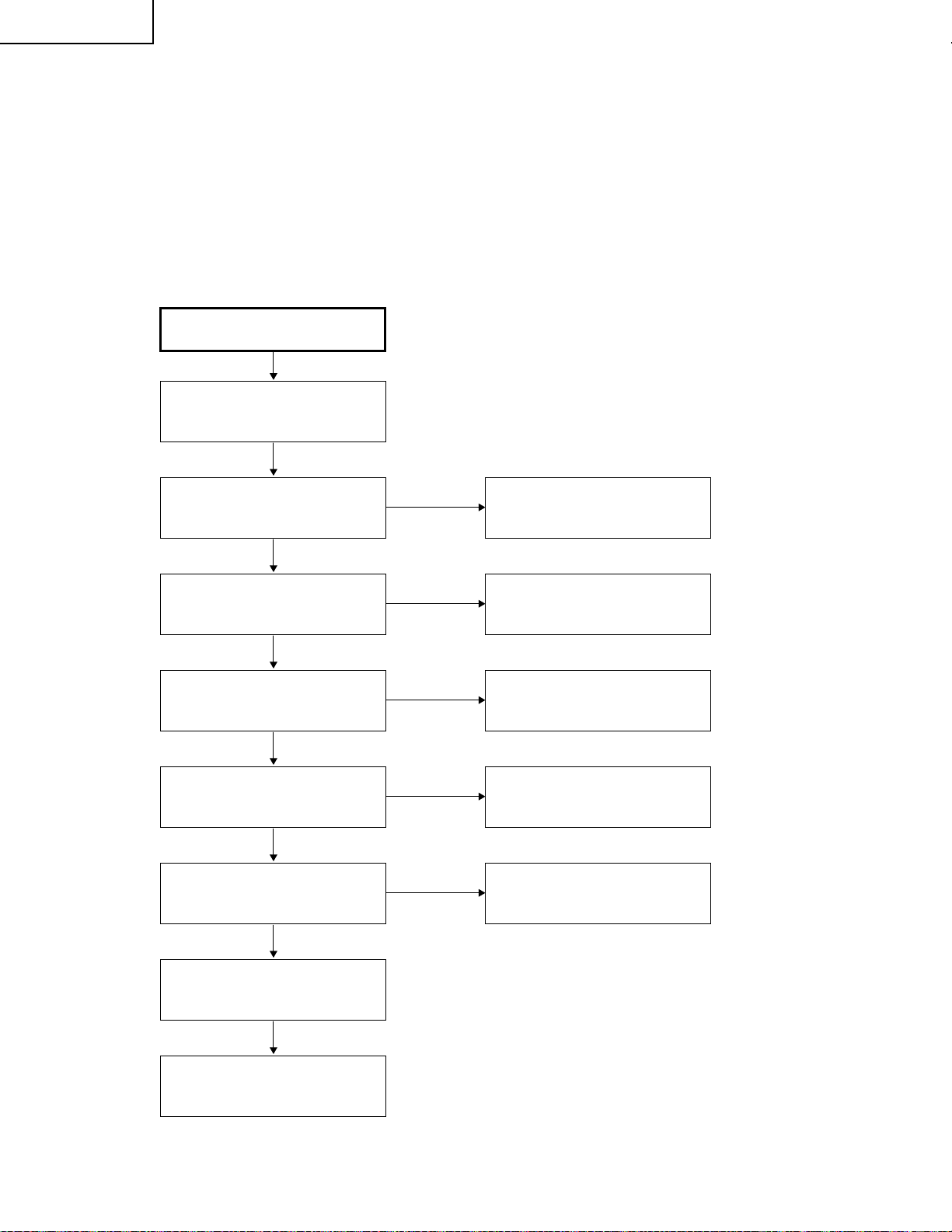
PG-M15X
PG-M15S
AN-M15T
1. Equipment Needed
» PG-M15X/S
» VGA Cable, Power Cord
» PC (Personal Computer)
» Audio Input, Video Input
» Screw Driver
2. Main Procedure
Connect AC cord, VGA cable
and audio signal, then turn
power on
TROUBLE SHOOTING TABLE
Start
Is Lamp light on?
Yes
Is Image OK?
Yes
Is function OK?
Yes
Is Audio OK?
Yes
Is Remote Control OK?
Yes
No
No
No
No
No
A. Power Troubleshooting
B. Image Performance
Troubleshooting
C. Function
Troubleshooting
D. Audio Troubleshooting
Change Remote Control unit
No Fault Found
End
30

2-1. A. Power Troubleshooting
Start
PG-M15X
PG-M15S
AN-M15T
Is LED indicator
OK?
Yes
Is Lamp OK?
Yes
Change Ballast
PWB unit
Yes
No
No
No
Check AC cord and
input power voltage
No
Supply
AC Cord
Change
Lamp unit
Main PWB unit
Troubleshooting
Yes
Lamp assembly
OK?
Yes
Change
DC to DC PWB unit
No
Main PWB unit
Troubleshooting
No
Change
Ballast PWB unit
No
Reassembly
lamp
End
31

PG-M15X
PG-M15S
AN-M15T
2-2. B. Performance Troubleshooting
Start
Have image?
Yes
Have garbage
pattern?
No
Uniformity OK?
Yes
Is color OK?
No
Have dot defect?
No
No
Yes
(White Screen)
No
No
Yes
Main PWB unit
Troubleshooting
Main PWB unit
Troubleshooting
Change
Optical Engine
Module
Main PWB unit
Troubleshooting
Change
DMD Module
No
Change
DMD Module
No
Change
DMD Module
No No
Change
DMD Module
Change
Optical Engine
Module
Have line bar?
No
Have noise?
No
End
Yes
Yes
Adjust
frequency
Adjust
tracking
No
No
Main PWB unit
Troubleshooting
Main PWB unit
Troubleshooting
32

2-2-1. White Screen or Garbage Pattern
Start
Check JP1 H, V SYNC in
Check U9 GH, GV SYNC
Check U17 Pin (5) DCLK
Check U16 Pin (5) MCLK
PG-M15X
PG-M15S
AN-M15T
End
2-2-2. Color abnormal (VGA)
Start
Check JP1 Pins (25), (26) and
(27)(RGB input)
Check U9 A/D coverter or
U7 (for DVI)
Check U11
Check JP2 is short circuit or not
Change DMD PWB unit
End
* When you fix it, suggest use white frame or RGBW color display.
33

PG-M15X
PG-M15S
AN-M15T
2-3. C. Function Troubleshooting
Start
Does OSD
No
show up?
Yes
Can function
No
be adjusted?
Yes
End
2-4. D. Audio Troubleshooting
Start
Can hear
No
sound?
Is SW PWB unit
OK?
No
Change
SW PWB unit
Main PWB unit
Troubleshooting
Main PWB unit
Troubleshooting
Yes
No
Is Remote
Controller OK?
No
Change
battery
No
Change
Remote Controller
Change
Spearker
Yes
Main PWB unit
Troubleshooting
Yes
Sound is clear
without noise?
Yes
End
No
Main PWB unit
Troubleshooting
34

3. Main PWB unit Troubleshooting
»»
» Condition-1.
»»
PC Source
Check VGAIN-R/G/B,
HSYNCIN, VSYNCIN PATH
PG-M15X
PG-M15S
AN-M15T
Check U9 AD9886
Yes
Check U11 PW164
Yes
DMD PWB unit
»»
» Condition-2.
»»
VIDEO Source
S-VIDEO Source
Check CY_out, C_out/Y_out,
PATH
No
Change AD9886
No
Change PW164
Check U40 ADG663
Yes
Check U24 VPC3230
Yes
Check U11 PW164
Yes
DMD PWB unit
No
Change ADG663
No
Change VPC3230
No
Change PW164
35

PG-M15X
PG-M15S
AN-M15T
»»
» Condition-3.
»»
Component-i Source
Check Cr/Pr, YIN, Cb/Pb
PATH
Check U2 LT1399
Check U24 VPC3230
Check U11 PW164
DMD PWB unit
»»
» Condition-4.
»»
DVI Source
No
Change LT1399
Yes
No
Change VPC3230
Yes
No
Change PW164
Yes
Check
RX0+/RX0-,
RX1+/RX1-,
RX2+/RX2-,
RXC+/RXC-,
PATH
Check U7 Sil151A
Yes
Check U11 PW164
Yes
DMD PWB unit
No
Change Sil151A
No
Change PW164
36

»»
» Condition-5.
»»
PC Source Output
PG-M15X
PG-M15S
AN-M15T
Check U3 LT1399
MONITOR DISPLAY
»»
» Condition-6.
»»
AUDIO Source
Check U22 LM4832
Check U23 LM4871
No
Change LT1399
Yes
No
Change LM4832
Yes
No
Change LM4871
Yes
SPEAKER OUTPUT
»»
» Condition-7.
»»
RREMOTE MOUSE
Check IR RECEIVER
Front : JP3
Back : IR1
Yes
Check U25 CY7C63612
Yes
REMOTE MOUSE CONTROL
No
Change IR RECEIVER
No
Change CY7C63612
37
 Loading...