

Page 1
: May 15 2006
1
INSTALLATION MANUAL
CODE: 00ZMX3500NI1E
DIGITAL FULL COLOR
MULTIFUNCTIONAL SYSTEM
MX-3500N/4500N
MODEL
CONFIGURATION
[1] MX-3500N/4500N, MX-3501N/4501N (Main unit). . . . . . . . . . . . . . 1-1
[2] MX-DEX3/DEX4 (Stand/1x500 sheet paper drawer,
Stand/2x500 sheet paper drawer) . . . . . . . . . . . . . . . . . . . . . . . . . . 2-1
[3] MX-TRX2 (Exit tray unit) . . . . . . . . . . . . . . . . . . . . . . . . . . . . . . . . . 3-1
[4] MX-LCX1 (Large capacity tray). . . . . . . . . . . . . . . . . . . . . . . . . . . . 4-1
[5] MX-FNX1 (Finisher) . . . . . . . . . . . . . . . . . . . . . . . . . . . . . . . . . . . . 5-1
[6] MX-PNX1A/B/C/D (Punch module (For Inner Finisher)) . . . . . . . . . 6-1
[7] MX-RBX1, MX-FNX2 (Paper pass unit, Saddle stitch finisher). . . . 7-1
[8] AR-PN1A/B/C/D (Punch module (For Saddle stitch finisher)). . . . . 8-1
[9] MX-FRX2, MX-FRX2U (Data security kit) . . . . . . . . . . . . . . . . . . . . 9-1
[10] MX-PKX1 (PS3 expansion kit) . . . . . . . . . . . . . . . . . . . . . . . . . . . 10-1
MX-3501N/4501N
CONTENTS
[11] AR-PF1 (Barcode font kit). . . . . . . . . . . . . . . . . . . . . . . . . . . . . . . 11-1
[12] MX-AMX1 (Application integration module) . . . . . . . . . . . . . . . . . 12-1
[13]
1
[14] MX-FXX1 (Facsimile expansion kit) . . . . . . . . . . . . . . . . . . . . . . . 14-1
[15] MX-FWX1 (Internet Fax expansion kit) . . . . . . . . . . . . . . . . . . . . . 15-1
Parts marked with " " are important for maintaining the safety of the set. Be sure to replace these parts with
specified ones for maintaining the safety and performance of the set.
This document has been published to be used
SHARP CORPORATION
for after sales service only.
The contents are subject to change without notice.
Page 2
: May 15 2006
1
MX3500N
CONFIGURATION
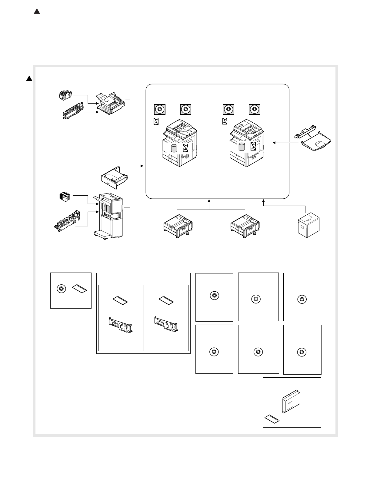
1. Configuration
A. Lineup (Main unit and option)
Service Manual
1
9. Punch module
●
●
●
●
10. Staple cartridge
(Approx. 5000 x 3)
(MX-SCX1)
8. Punch module
●
2-hole (MX-PNX1A)
●
3-hole (MX-PNX1B)
●
4-hole (MX-PNX1C)
●
4-hole (broad space)
(MX-PNX1D)
11. Staple cartridge
(Approx. 5000 x 3)
(AR-SC2)
2-hole (AR-PN1A)
3-hole (AR-PN1B)
4-hole (AR-PN1C)
4-hole (broad space)
(AR-PN1D)
7. Finisher
(MX-FNX1)
5. Paper pass unit
(MX-RBX1)
6. Saddle stitch finisher
(MX-FNX2)
PCL5c/PCL6
driver
RSPF
Network
scanner
(Sharpdesk 1 license)
*&&
Copier/Printer
/Scanner model
(MX-3500N)
(MX-4500N)
1. Stand/1x500 sheet
paper drawer
(MX-DEX3)
PCL5c/PCL6
driver
DSPF
Network
scanner
(Sharpdesk 1 license)
HDD
Copier/Printer
/Scanner model
(MX-3501N)
(MX-4501N)
2. Stand/2x500 sheet
paper drawer
(MX-DEX4)
4. Exit tray unit
(MX-TRX2)
3. Large capacity tray
(MX-LCX1)
12. Barcode font kit
CD
ROM
(AR-PF1)
(Including document control)
13. Commercial
version
Security
ROM
For document
control PWB
(MX-FRX2U)
Data security kit
14.
CC authentication
version
For document
control PWB
(MX-FRX2)
Security
ROM
15. PS3
expansion
kit
CD
(MX-PKX1)
19. Sharpdesk
10 license kit
20. Sharpdesk
50 license kit
CD
(MX-US10/
US50)
16. Internet Fax
expansion kit
CD
(MX-FWX1)
21. Sharpdesk
100 license kit
CD
(MX-USA0)
23. Facsimile expansion kit
17. Sharpdesk
1 license kit
18. Sharpdesk
5 license kit
CD
(MX-USX1/
USX5)
22. Application
integration
module
CD
(MX-AMX1)
(MX-FXX1)
FAX memory (8MB)
(packed together)
MX3500N CONFIGURATION - i
Page 3
: May 15 2006
1
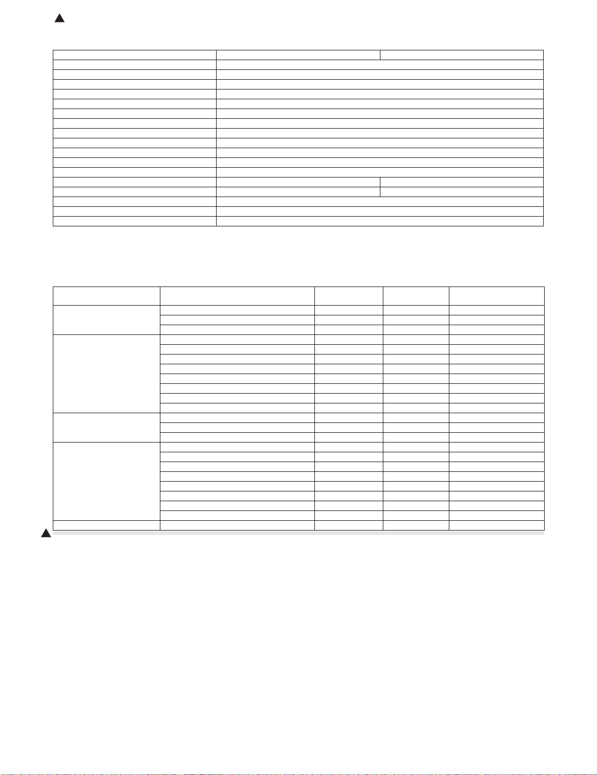
B. Machine configuration
Copier memory (Local memory) (MB) 768
Printer memory (System memory) (MB) 640
Copier STD
GDI printer STD
PCL printer STD
PS printer OP*1
EFI printer OP
Main body LCD MONOCHROME HVGA 8.9"
FAX OP*2
Scanner STD
Filing STD
HDD STD
RSPF STD –
DSPF –STD
Automatic duplex STD
Security OP*1
Internet Fax OP*1
MX-3500N/MX-4500N MX-3501N/MX-4501N
STD: Standard provision, OP: Option
OP*1: Product key target.
OP*2: No support for some areas.
C. Combination of options list
Section Name Model name
Paper feed system 1. Stand/1x500 sheet paper drawer MX-DEX3 OPT
2. Stand/2x500 sheet paper drawer MX-DEX4 OPT
3. Large capacity tray MX-LCX1 OPT (A4)
Paper exit system 4. Exit tray unit MX-TRX2 OPT
5. Paper pass unit MX-RBX1 OPT
6. Saddle stitch finisher MX-FNX2 OPT
7. Finisher MX-FNX1 OPT (Inner finisher)
8. Punch module (For inner finisher) MX-PNX1 A/B/C/D OPT
9. Punch module (For saddle stitch finisher) AR-PN1 A/B/C/D OPT (Common in current models)
10. Staple cartridge (For inner finisher) MX-SCX1 OPT (Approx. 5000 x 3)
11. Staple cartridge (For saddle stitch finisher) AR-SC2 OPT (Approx. 5000 x 3)
Electrical system (ROM) 12. Barcode font kit AR-PF1 OPT (Conventional model)
13. Data security kit MX-FRX2U OPT (Commercial version)
14. Data security kit MX-FRX2 OPT (Authentication version)
Electrical system (Software) 15. PS3 expansion kit MX-PKX1 OPT
16. Internet Fax expansion kit MX-FWX1 OPT (Internet Fax)
17. Sharpdesk 1 license kit MX-USX1 OPT
18. Sharpdesk 5 license kit MX-USX5 OPT
19. Sharpdesk 10 license kit MX-US10 OPT
20. Sharpdesk 50 license kit MX-US50 OPT
21. Sharpdesk 100 license kit MX-USA0 OPT
22. Application integration module MX-AMX1 OPT
Electrical system (FAX) 23. Facsimile expansion kit MX-FXX1 OPT*1
1
STD: Standard provision. OPT: Installable option.
*1: No support for some areas.
MX-3500N/3501N
MX-4500N/4501N
Remarks
MX3500N CONFIGURATION - ii
Page 4
MX3500N
[1] MX-3500N/4500N, MX-3501N/4501N
Service Manual
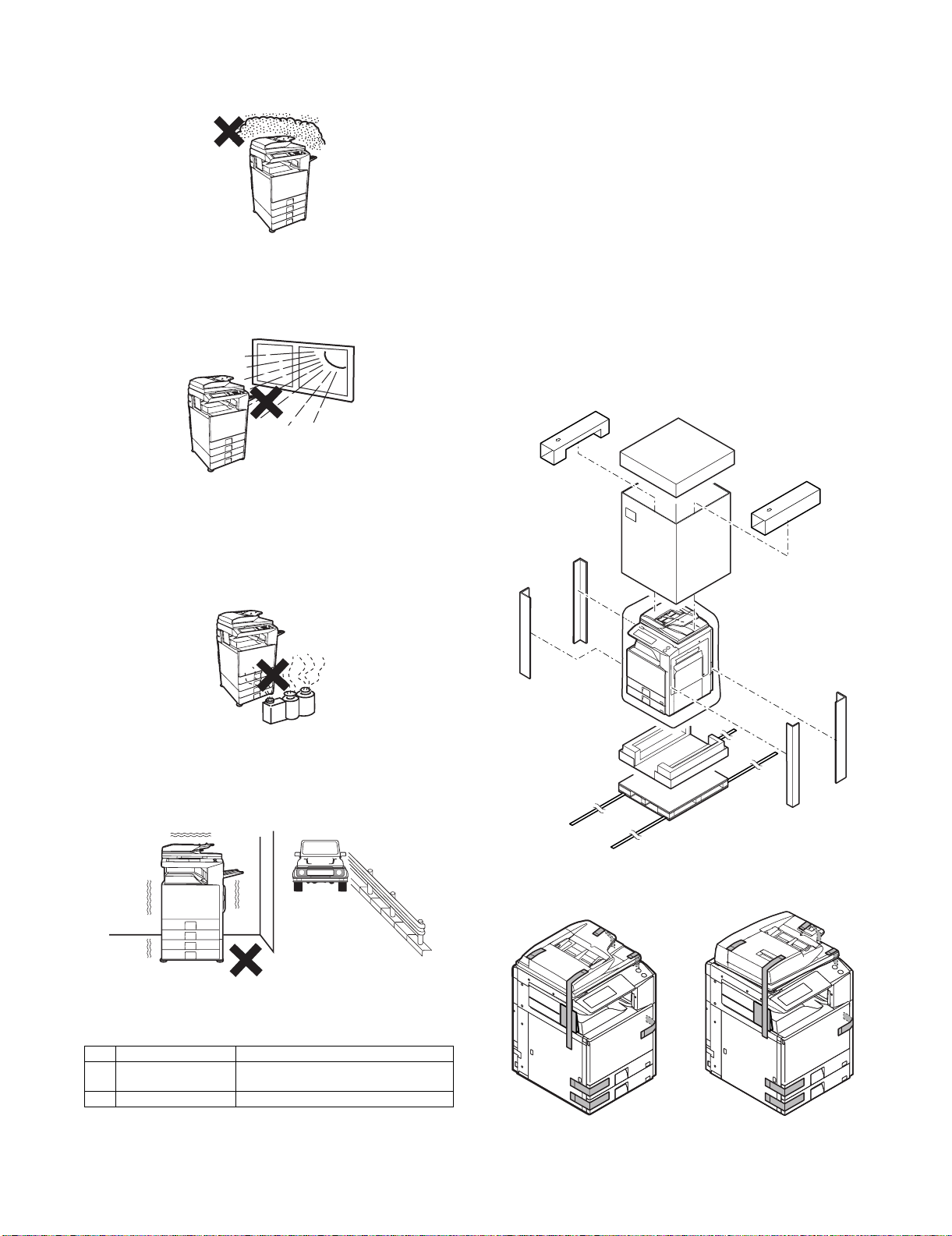
1. Installing (use) conditions
Before installing the machine, check that the following installing
(use) conditions are satisfied.
If the installing (use) conditions are not satisfied, the machine may
not display full performances, resulting in troubles. It may also
cause safety problems. Therefore, be sure to arrange the installing
(use) conditions before setting up the machine.
No. Content
1 Bringing space
2 Installing space
3 Power source (Capacity, fluctuation, safety)
4 Floor strength
5 Direct rays of the sun, dust, temperature, humidity, gases,
chemicals
A. Bringing space
For installation of a large size machine, be sure to check that the
door size is great enough before bringing in.
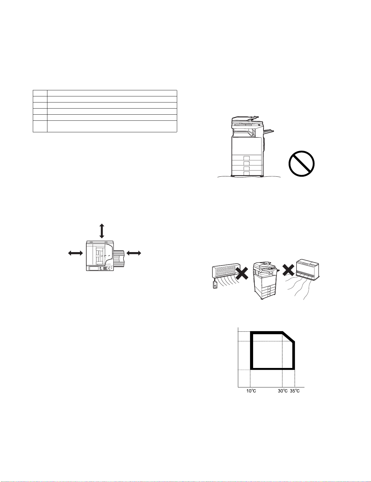
B. Installing space
The following space must be provided around the machine in order
to assure machine performances and proper operations.
If any option is installed, provide the additional space for installing
it.
Especially the space at the rear of the machine must be provided
sufficiently. If not, the machine cannot exhibit functions against heat
and dust, causing some troubles.
30 cm
30 cm
45 cm
(4) Safety
Be sure to properly ground the machine.
(5) Power plug
Check the form of the power plug. If the shape does not match, do
not use it.
D. Floor strength and level
This machine is considerably heavy and becomes heavier with an
option installed.
The floor must be strong enough for assuring safety.
If not, color shift or image distortion may occur.
E. Direct rays of the sun, dust, temperature,
humidity, gasses, chemicals, vibration
(1) Temperature and humidity
This machine is designed to perform properly under the specified
temperature and humidity. If the temperature and humidity exceeds
the specified range, the machine may not operate properly and or
cause equipment failure.
Especially when the humidity is too high, paper absorbs humidity to
cause a paper jam or dirty copy.
Do not install the machine near a heater, a cooler, or a humidifier.
C. Power source (Capacity, voltage, frequency,
safety, plug)
If the power specifications are not satisfied, the machine cannot
exhibit full performances and may cause safety trouble.
Strictly observe the following specifications.
(1) Power capacity
Check that the following power capacity is satisfied. If not, additionally provide a power source.
Current capacity
Japan: 20A or more
100V: 15A or more
200V: 10A or more
(2) Power voltage
Measure the voltage during copying to check that the voltage is in
the range of the specified voltage ±10%.
If the voltage is outside the specified range, use thicker lead wires
to reduce impedance.
(An electrical work is required.)
Use of a step-up transformer is also available. In this case, the
capacity must be great enough for the max. power consumption of
the machine.
(3) Power frequency, waveform
The frequency must be within the range of the specified frequency
±2%. If power waveform is deformed, a trouble may occur.
Dew may be formed inside the machine to cause a trouble. Use
enough care for ventilation.
Humidity㧔RH㧕
85%
60%
20%
• Working environment
Temperature: 10 to 35°C
Humidity: 20 to 85% RH
Atmospheric pressure: 590 to 1013hPa (altitude: 0 to 2000 m)
MX-3500N/4500N, MX-3501N/4501N 1 – 1
Page 5
(2) Dust
If dust enters the machine, it may cause dirty copy and a paper
jam, resulting in a shortened lifetime.
(3) Direct rays of the sun
If the machine is installed under the rays of the sun, the exterior of
the machine may be discolored and abnormal copies may be produced.
(4) Gases and chemicals
Do not install the machine at a place where there are gases and
chemicals. Especially be careful to avoid installation near a diazotype copier, which produces ammonium gas.
Copy quality may be adversely affected and a trouble may be
caused.
A. Implements, facility, and manpower
It is recommendable to use a forklift for bringing in the machine for
safety.
If no forklift is available, man-power of four persons is required. The
machine is considerably heavy, and requires safety precautions for
delivery and installation.
Transit of the machine must be made in packed condition to the
installing place.
Since the hard disk drive is built in the machine, use care not to
exert vibrations or shocks to the machine when in transit.
B. Delivery
Remove the packing materials prior to installation in the office environment.
3. Unpacking
A. Unpacking procedure
1) Remove the PP band.
2) Remove the top case.
3) Remove the internal packing pads with the machine.
(5) Vibration
Avoid installation near a machine which produces vibrations.
If vibrations are applied to the copier machine, copy images may be
deflected and a trouble may be caused.
2. Transit and delivery
No. Content Method
1 Implements, facility,
and man power
2 Delivery Transit must be made in packed condition.
Use a forklift. (If no forklift is available,
manpower of four persons is required.)
MX-3500N/4500N, MX-3501N/4501N 1 – 2
B. Fixing tape and protection pads removal
Page 6
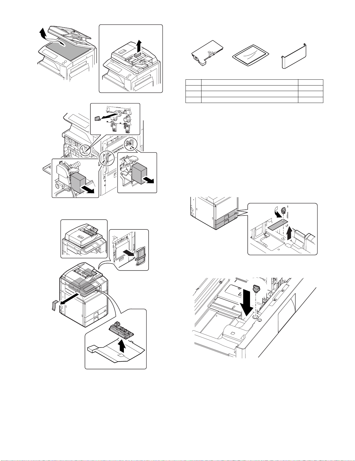
DSPF MODEL ONLY
D. Check the parts packed together
1) Check that all the parts are in the package.
12 3
No. Parts name Quantity
1 Waste toner bottle unit 1
2 Operation manual 1
3 Operation manual pocket 1
4. Installation
<Note before installation>
* When connecting the main unit with the optional one-tier paper
feed desk (MX-DEX3) or two-tier paper feed desk (MX-DEX4),
first unpack and install the one-tier paper feed desk (MX-DEX3)
or two-tier paper feed desk (MX-DEX4); then unpack the main
unit and securely place the main unit on the MX-DEX3 or MXDEX4 (see 2-2) before installing the main unit.
A. Lock release
(1) Tray rotation plate lock release
1) Pull out the tray, and remove the rotation plate fixing material
and the tray note label.
C. Removal of parts packed together
2) Attach the removed fixing material to the position shown in the
figure for storage.
MX-3500N/4500N, MX-3501N/4501N 1 – 3
Page 7
(2) Scanner (2/3 mirror unit) lock release
1) Remove the optical unit fixing screw, and remove the note
label.
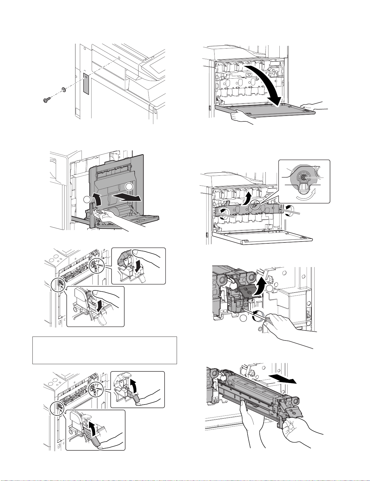
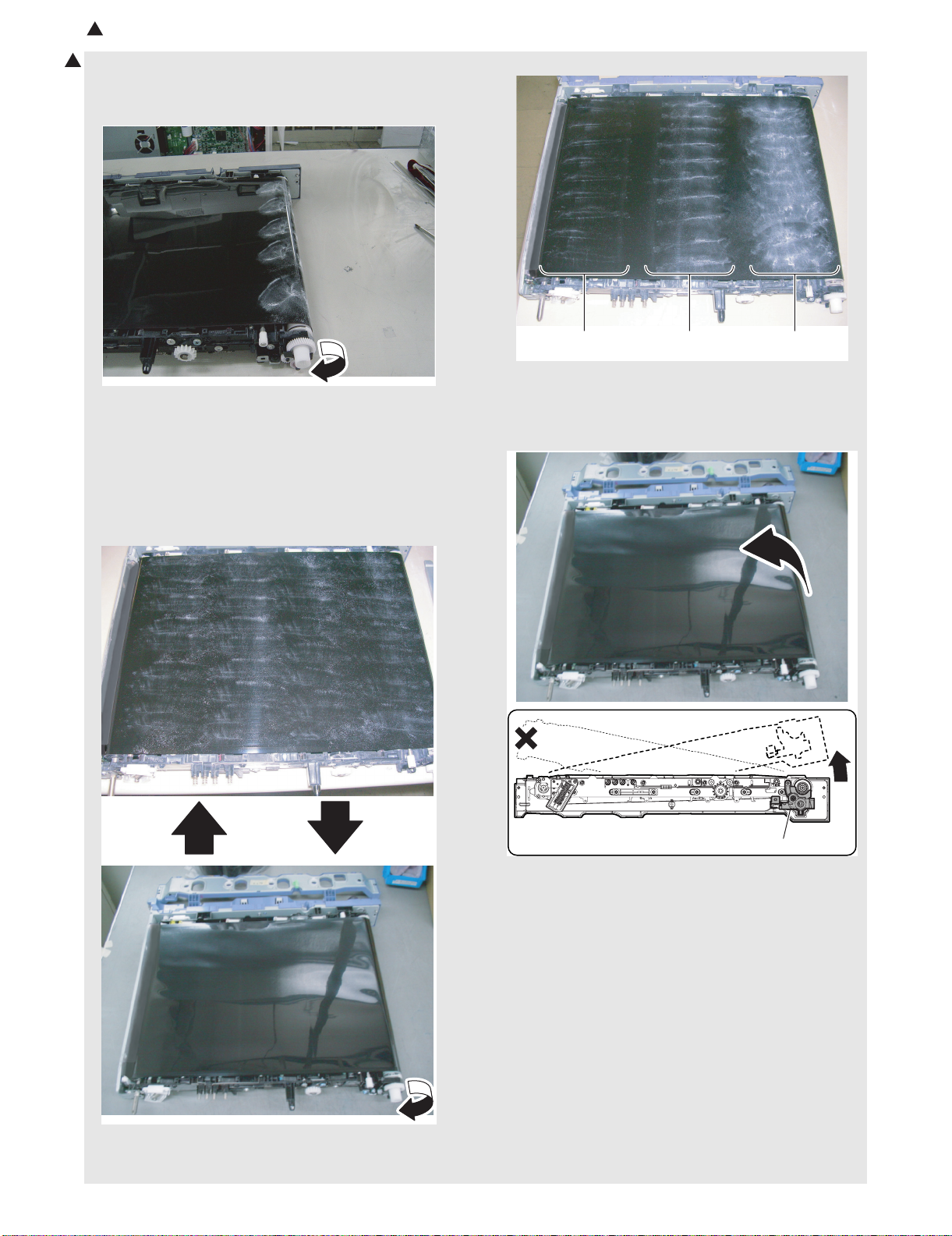
C. Primary transfer and transfer belt protection
sheet disassembly/cleaning roller pressing
1) Open the front cover.
B. Fusing heat roller pressing (F/R)
1) Open the right door.
2
1
2) Lower the pressure release lever to apply more pressure.
2) Check that the lock is released as shown in (A).
Loosen the blue screw, and open the drum positioning unit.
* When the lock is not released, use a screwdriver to turn the
screw (B) counterclockwise so that it is fit as (A).
A
B
3) Open the DV lock lever, and release the fixing screw. (1 position for each color)
1
NOTE:
If the machine is left unused for one month or more, the heat
roller rubber may be deformed. In such a case, release the
pressure by pushing up both levers.
MX-3500N/4500N, MX-3501N/4501N 1 – 4
2
4) Pinch the knob and remove the development unit.
Page 8
: Nov. 15 2006
4
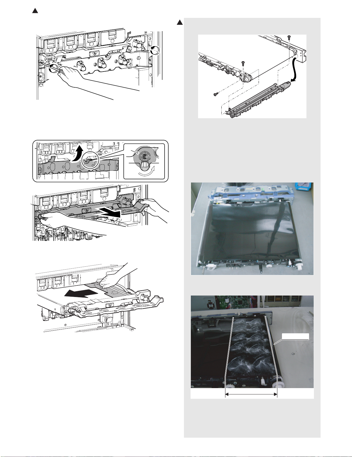
5) Loosen the blue screw.
6) Turn the blue screw (A) counterclockwise. Check to insure that
the lock is released as shown with (B), and pull out the primary
transfer unit toward you.
* If this procedure is not executed, the intermediate transfer
belt may be damaged.
B
A
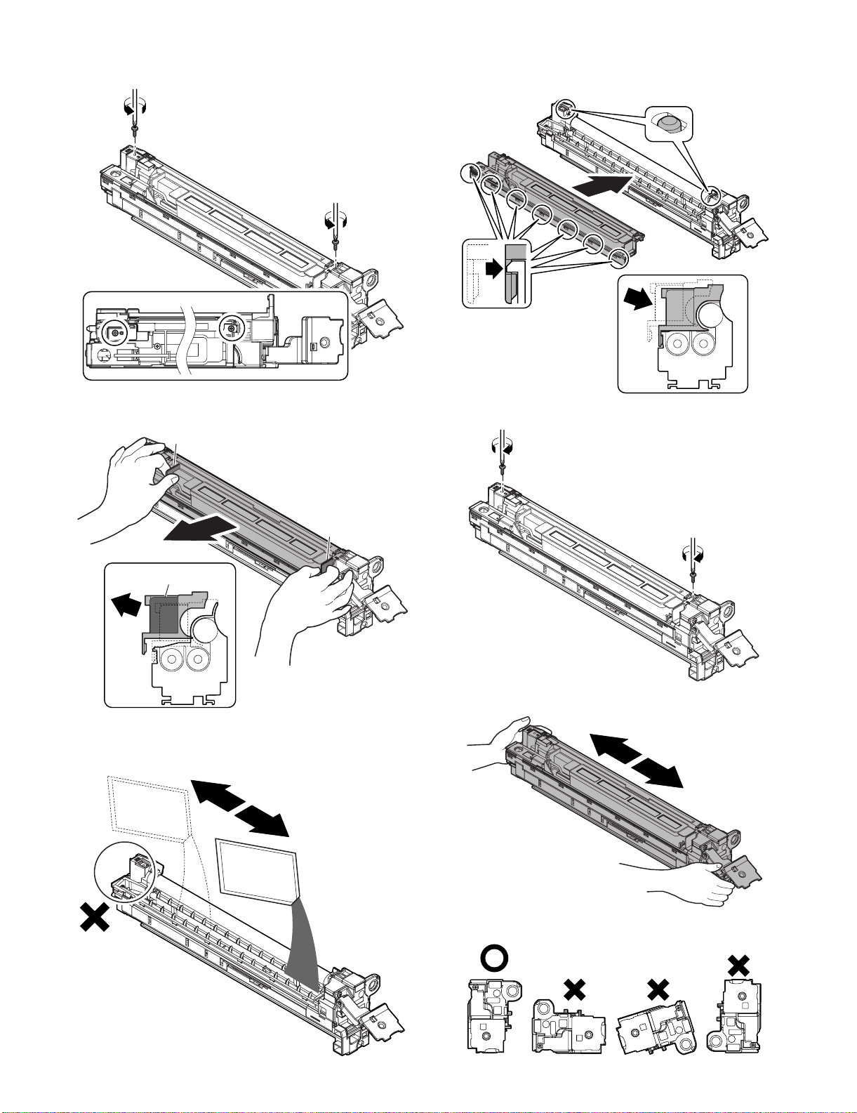
D. Applying titanium hydroxide
4
1) Remove the cleaner unit.
* Since titanium hydroxide is of fine powder, it may disperse
when removing from the bag. To prevent against dispersion,
remove it from the bag at a lower position.
* Pushing the bag lightly against the belt provides sufficient
application of titanium hydroxide. Lift the bag from the application surface by 5 mm or less.
* Apply titanium hydroxide before installing the cleaner unit.
2) Install the primary transfer UN with its backside facing upward
and remove the cleaner frame UN.
7) Remove the transfer belt protect sheet horizontally in the arrow
direction.
3) Apply titanium hydroxide to the belt within approx. 15 cm from
the driving roller.
Driving roller
15cm
MX-3500N/4500N, MX-3501N/4501N 1 – 5
Page 9
: Nov. 15 2006
4
4) Rotate the belt by amount 10 cm to move the application part
4
to the surface.
* Till the applied powder reaches the cleaner installation loca-
tion.
(Application amount)
5) Mount the cleaner frame UN on the primary transfer UN.
6) Apply titanium hydroxide to the belt.
* Apply titanium hydroxide to the belt 40 times (10 times in lat-
itudinal direction x 4 times in longitudinal direction) for
4 faces (making two circuits of the belt).
* Repeat half-around application and half-around rotation
each 4 times.
* Apply titanium hydroxide not to produce bias.
Little Moderate
Much
amount
7) Face the primary transfer UN upward.
* Face the primary transfer UN UPward from the cleaner UN
side.
* Take care that powders will not fly apart.
8) Mount the primary transfer UN on the machine and execute
simulation 25-1 (3-minute belt idling) once.
9) Check omissions in characters, and if many omissions are
found, execute simulation 25-1 once again.
10) If titanium hydroxide flies apart near the resist roller, clean it.
MX-3500N/4500N, MX-3501N/4501N 1 – 6
Cleaner UN
Page 10
E. Developing (each color) installation
1) Remove two fixing screws of the DV cover.
4) Install the DV cover in the arrow direction (A).
* When installing the DV cover, be sure to engage the pawl
with the boss.
A
A
2) Hold the sections A, and remove the DV cover in the arrow
direction (B).
A
B
A
A
B
3) Supply developer in the developer unit.
* When replacing developer, use an extreme care not to drop
developer on the drive section (marked with {).
5) Fix the DV cover with the two screws.
6) Shake the developer unit horizontally a few times.
* When supplying developer, do not tilt the developing unit.
MX-3500N/4500N, MX-3501N/4501N 1 – 7
Page 11

7) Install each developer unit.
ON
ON
* When installing the developer unit, be sure to check that the
DV lock lever is open.
F. Set the control level for the reference toner
density
1) Connect the earth cord and insert the power plug into the
power outlet.
8) Fix it with the fixing screw. Insert the DV lock lever until it clicks
and close.
2
1
9) Close the drum positioning unit, and tighten the blue screw.
2) Turn ON the power switch in the front cabinet.
ON
3) Turn ON the power switch on the operation panel.
10) Install the waste toner bottle unit (package part No. 1).
MX-3500N/4500N, MX-3501N/4501N 1 – 8
4) With the front cabinet open, enter the data for Simulation 25-2.
0
SIMULATIONNO.25-02
TEST
AUTOMATIC DEVELOPER ADJUSTMENT
:
AT DEVE ADJ_L_K
AT DEVE ADJ_L_C
AT DEVE ADJ_L_M
AT DEVE ADJ_L_Y
K
128
:
128
:
128
:
128
C
M
Y
AT DEVE VO_L_K
AT DEVE VO_L_C
AT DEVE VO_L_M
AT DEVE VO_L_Y
:
:
:
:
128
128
128
128
EXECUTE
CLOSE
1/2
Page 12
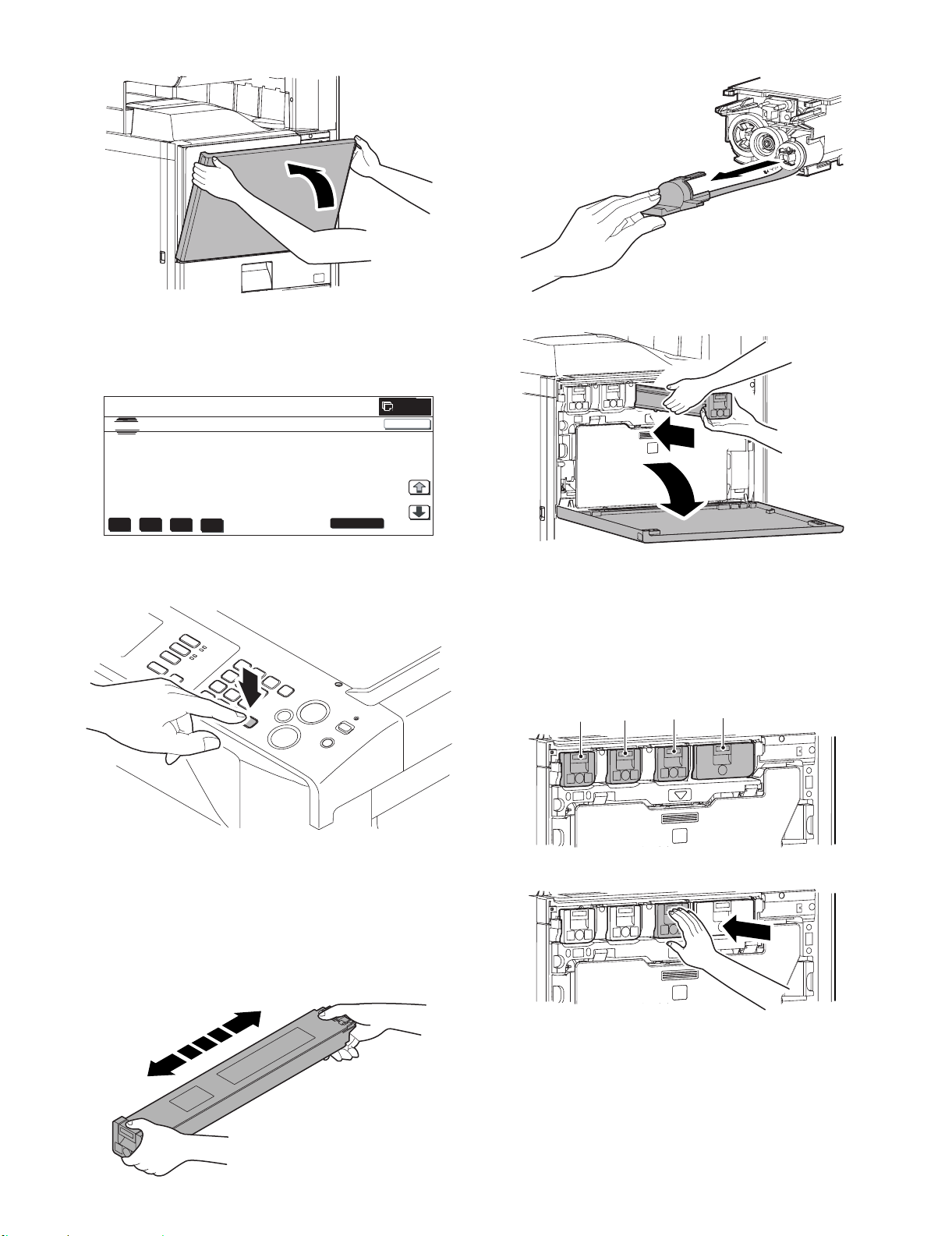
5) After entering the data, close the front cabinet.
2) Remove the heat seal.
6) Select K, C, M, Y and then press the [EXECUTE] button. The
system then performs the simulation, samples the toner density control sensor value, and sets (stores in memory) the
average sensor detection level as the control level for the reference toner density.
0
SIMULATIONNO.25-02
TEST
AUTOMATIC DEVELOPER ADJUSTMENT
:
AT DEVE ADJ_L_K
AT DEVE ADJ_L_C
AT DEVE ADJ_L_M
AT DEVE ADJ_L_Y
K
128
:
128
:
128
:
128
C
M
Y
AT DEVE VO_L_K
AT DEVE VO_L_C
AT DEVE VO_L_M
AT DEVE VO_L_Y
:
:
:
:
128
128
128
128
EXECUTE
CLOSE
1/2
Note: Be sure to select all of the four colors: K, C, M, Y.
7) Exit from Simulation mode by pressing the [CA] key on the
main unit.
3) Open the front cover, and insert each toner cartridge.
* Be sure to install the color cartridges to their proper posi-
tions. Avoid installation to a different color position.
* Do not forcibly insert the toner cartridge.
Keep holding the cartridge and completely insert it.
* When the machine is transported with the developing unit
removed, be sure to remove the toner cartridge. (If not, tone
may be clogged.)
[Color toner cartridge positions]
Y M C
BK
G. Installation of individual color toner cartridges
* The life of each toner cartridge is as follows:
Black toner cartridge: equivalent to approximately 18K (A4/LT
5%)
Color toner cartridge: equivalent to approximately 15.0K (A4/LT
5%)
1) Shake the toner cartridge (package part No. 1) horizontally
several times.
MX-3500N/4500N, MX-3501N/4501N 1 – 9
4) Insert the cartridge securely until it locks.
Page 13
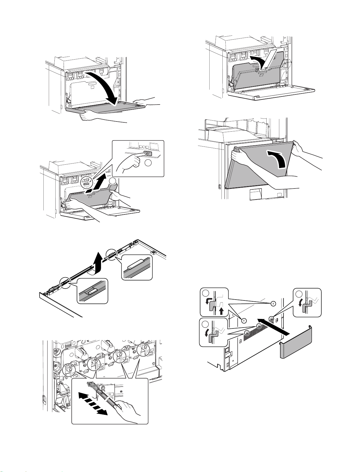
H. Cleaning of LSU's dust-proof glass
* Dust from the transfer belt or shutter or some other adjacent part
may fall onto the LSU during transport or installation. Be sure to
clean the dust-proof glass before checking the image quality.
1) Open the front cover.
2) Remove the waste toner bottle unit.
1
2
5) Replace the LSU claning bar to the front cover and attach the
waste toner bottle unit.
6) Close the front cabinet.
3) Detach the LSU cleaning bar from the front cover.
4) Insert the LSU cleaning rod, and slide it back and forth a few
times to clean the LSU dust-proof glass.
I. Installation of the operation manual pocket
1) Install the Operation Manual storage (package part No. 3)
cover to the left side of the machine.
First, insert the pawl on the lower side of the Operation Manual
pocket.
Then, lift the pawl on the upper side and insert it, and slide
down to install.
* If the MX-FNX2 (saddle finisher) is installed together with
installation of the machine, the Operation Manual storage
cover must be installed to the saddle finisher.
For details, refer to [7] MX-FNX2.
2
1
1
MX-3500N/4500N, MX-3501N/4501N 1 – 10
Page 14

J. Tray setup
B
A
(1) Simulation setup
This is used to specify the paper type, paper size, and functions
used for each paper tray.
1) Press the [SYSTEM SETTINGS] key.
SYSTEM
SETTINGS
2) Touch the [Paper Tray Settings] key.
System Settings
Admin Password
Exit
6) Select the paper size.
(1) Touch the desired paper size.
(2) Touch the [OK] key.
System Settings
Tray 1 Type/Size Setting
Type
Plain
A3 A4 A4R
A5R
B5R
Size
B4
1
/
2
216x330(8 x13)
(2)(1)
Type OK
1/3
B5
2/2
Total Count
Paper Tray
Settings
Printer Condition
Settings
Default Settings
Address Control
Document Filing
Control
List Print
(User)
Fax Data
Receive/Forward
USB-Device Check
3) Touch the [Tray Settings] key.
System Settings
Paper Tray Settings
Tray Settings
Paper Type Registration
Auto Tray Switching
4) Select the tray that you wish to configure.
(1) If needed, use the [↓] [↑] keys to switch through the trays.
(2) Touch the [Type/Size] key.
System Settings
Paper Tray Settings
Tray 1
Print Copy Fax
Type / Size
Plain / A4
I-Fax
Doc.
Filing
Fixed Paper Side
Disable Duplex
Disable Staple
Disable Punch
(2)(1)
System Settings
Tray 1 Type/Size Setting
Type Size
1
Plain
OK
11x17
1
/
8 x11
2
/
2
8 x14
1
1
/
7x10R
4
/
2
Type OK
1
/
2
8 x11
1
1
/
/
5x8R
2
2
2/3
2/2
(2)(1)
System Settings
Tray 1 Type/Size Setting
Type
Plain
OK
1/6
(2) Tray size setup
1) Pull out the paper tray.
Gently pull the tray out until it stops.
8K 16K 16KR
Size
If paper remains in the tray, remove it.
Type OK
3/3
2/2
5) Touch the desired paper type.
Example: Tray 1 is selected
System Settings
Tray 1 Type/Size Setting
Select the paper type.
Plain Letter Head
Pre-Printed Pre-Punched
Recycled Colour
System Settings
Tray 1 Type/Size Setting
Select the paper type.
User Type 1 User Type 2
User Type 5 User Type 6 User Type 7
User Type 3 User Type 4
MX-3500N/4500N, MX-3501N/4501N 1 – 11
Cancel
Cancel
(1)(2)
2) Adjust the guide plates A and B by squeezing their lock levers
1/2
1/2
2/2
1/2
and sliding them to match the vertical and horizontal dimensions of the paper to be loaded.
The guide plates A and B are slidable. Slide each guide plate
while squeezing its lock lever.
Page 15
: Nov. 15 2006
4
K. Specifications setup
Used to set the specifications with SIM26 according to the customer's request.
SIM No Content
26 6 Used to set the destination.
To customize the following items after completion of the destination
setup, change the set values.
SIM No Content
26 2 LCC paper size setting
3 Used to set the auditor specification mode.
5 Used to set the count mode of the total counter and the
maintenance counter.
18 Used to set YES/NO of the toner save mode (Only in UK and
Japan versions)
* For other destination versions, this setup is made by the
user program.
52 Used to set YES/NO of counting when non-print paper is
passed through each counter.
53 Used to set YES/NO of user calibration permission.
54 Used to set the printer calibration YES/NO.
65 Used to set the limit number of sheets for stapling.
L. Image quality check
Check the following items related to image quality. For details of the
adjustment and checking procedures, refer to the “[6] ADJUSTMENT” on the Service Manual.
(1) Image skew (see ADJ 6)
1) Enter SIM61-4 mode.
2) Check the printed black image for skew.
3) If the adjustment is required, adjust skew by changing the LSU
fixing position.
(2) Image resist (see ADJ 10)
• Main scanning direction, sub scanning direction (Auto
adjustment)
1) Enter SIM50-22 mode.
2) Press [REGIST] key to select the image registration adjustment auto adjustment mode.
• Main scanning direction (Manual adjustment)
1) Enter SIM50-20 mode.
2) Check the rough adjustment and the fine adjustment print pattern positions of each color in the front frame and the rear
frame sides.
3) If the adjustment is required, adjust resist (main scanning
direction) by changing the setting value.
• Sub scanning direction (Manual adjustment)
1) Enter SIM50-21 mode.
2) Check the rough adjustment and the fine adjustment print pattern positions of each color.
3) If the adjustment is required, adjust resist (sub scanning direction) by changing the setting value.
(3) Image loss, void area (see ADJ 17, ADJ 18)
• ADJ 17: Print area (Void area) adjustment (Print engine sec-
tion)
1) Enter the simulation 50-10 mode.
2) Check the adjustment pattern to confirm that the items below
are in the range of the standard values.
• ADJ 18: Copy image position, image loss adjustment
Document table mode
1) Place a scale on the document table.
2) Enter the simulation 50-1 mode.
3) Perform the image lead edge reference position adjustment.
4) If the adjustment is required, adjust image lead edge reference
position by changing the setting value.
5) Perform the image loss adjustment.
• Copy image position, image loss adjustment (RSPF mode)
(Refer to the MX-RPX1 SM.)
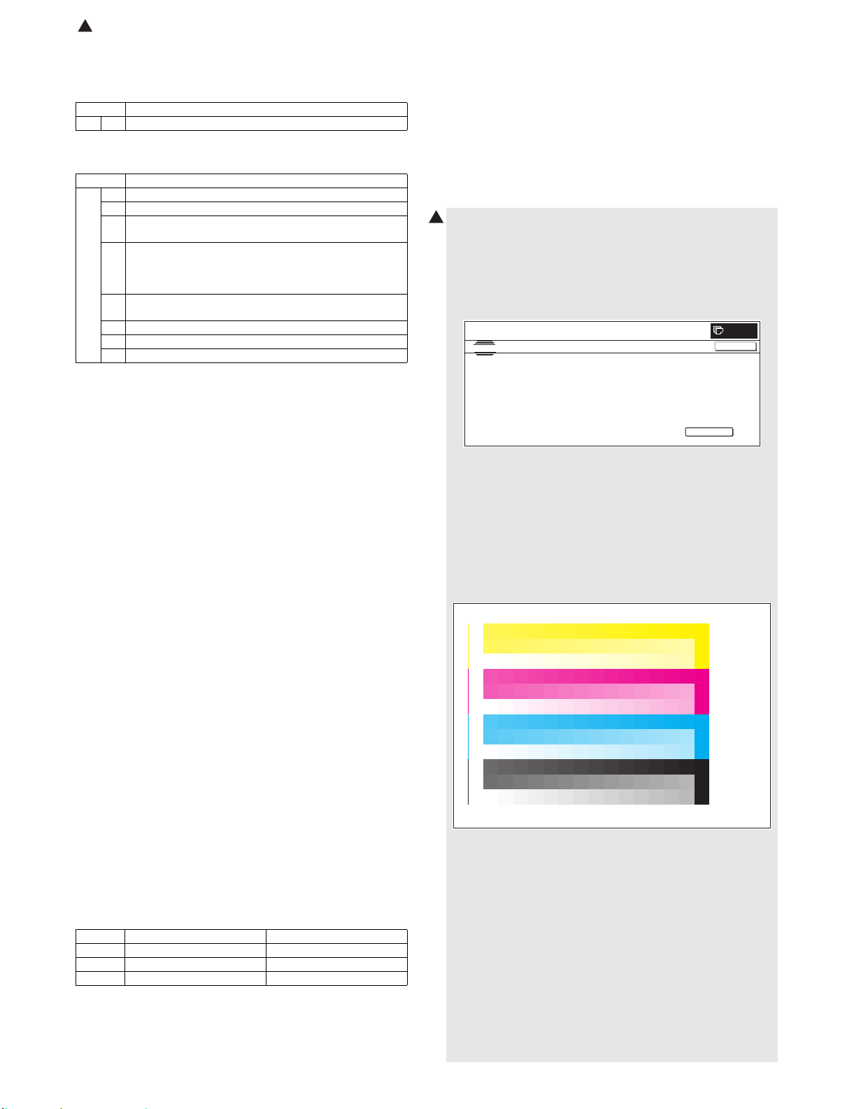
(4) Copy color balance adjustment (Auto adjustment)
4
a. Note before execution of the copy color balance
adjustment (Auto adjustment)
• Be sure to use the specified paper for color.
b. Adjustment procedure
1) Enter the SIM 46-24 mode.
SIMULATIO NNO.46-24
TEST
ENGINE HALFTONE AUTO ADJUSTMENT
PRESS [EXECUTE] TO PROCON EXECUTIONANDPRIN T TH ETESTPATCH.
(PLEASE U S E S PECIFIE D TYPE OF A 3 OR 11”
17” SIZ EPAPER
FOR THIS ADJUSTMENT
CLOSE
EXECUTE
2) Press [EXECUTE] key. (A3 or 11" x 17" paper is automatically
selected.)
The color patch image (adjustment pattern) is printed out.
3) Set the color patch image (adjustment pattern in procedure 2)
paper printed on the document table.
Place the printed color patch image (adjustment pattern) paper
so that the thin lines on the paper are on the left side. At this
time, place 5 sheets of white paper on the printed color patch
image (adjustment pattern) paper.
0
X Lead edge void area 3.0 ± 1.0mm
Y Rear edge void area 2.0 ± 1.0mm
Z1/Z2 FRONT/REAR void area 2.0 ± 2.0mm
Content Standard adjustment value
If the above condition is not satisfied, or if it is set to a desired
condition, execute the simulation 50-1.
MX-3500N/4500N, MX-3501N/4501N 1 – 12
Page 16
,
PRINTER CALIBRATION
: Nov. 15 2006
4
4) Press [FACTORY] key, and press [EXECUTE] key.
4
SIMULATIONNO. 46-2 4
TEST
ENGINE HALFTONE AUTO ADJUSTMENT
PLEASE SE LECT TH EMODE(FACTORY) OR ( SERVIC E) AND PLACE
THEPRINTEDTESTPATCH ON DOCUMENT GLAS S THEN PRESS [ EXECUTE].
,
㪁
LIGHTAREAATLEFTSIDEONDOCUMENTG LASS.
FACTORY
SERVICE
EXECUTE
The copy color balance adjustment is automatically executed
and prints the color balance check patch image.
5) Press [OK] key.
SIMULATIO NNO. 46-24
TEST
ENGINE HALFTONE AUTO ADJUSTMENT
CONFIRM THEADJUSTEDPATCH AND P RESS [OK] TO REGISTER THIS PATCH DATA
PRESS [REPEAT] TO CONTIN U E TH IS PROCEDURE.
REPEAT
Note:
Do not cancel the simulation until "PLEASE QUIT THIS
MODE" is displayed.
SIMULATIONNO. 46-24
TEST
ENGINE HALFTONE AUTO ADJUSTMENT
COMPLETED THIS PROCEDURE.
PLEASE QUIT THIS MODE.
OK
CLOSE
CLOSE
CLOSE
CLOSE
(5) Printer color balance adjustment
(Auto adjustment)
0
a. Note for execution of the color balance adjustment
(Auto adjustment)
• The copy color balance adjustment must have been completed
properly.
• Be sure to use the specified paper for color.
b. Adjustment procedure
1) Enter the SIM 67-24 mode.
0
SIMULATIONNO.67-24
TEST
PRINTER ENGINE HALFTONE AUTO ADJUSTMENT M ODE
PRESS [EXECUTE] TO PROCON EXECUTION AND PRINT THETESTPATCH.
0
(PLEASE USE SPECIFIED TYPE OF A3 OR 11”
17” SIZEPAPER
FOR THIS ADJUSTMENT
CLOSE
EXECUTE
2) Press [EXECUTE] key. (A3 or 11" x 17" paper is automatically
selected.)
The color patch image (adjustment pattern) is printed out.
3) Set the color patch image (adjustment pattern) paper printed
on the document table.
Place the printed color patch image (adjustment pattern) paper
so that the thin lines on the paper are on the left side. At this
0
time, place 5 sheets of white paper on the printed color patch
image (adjustment pattern) paper.
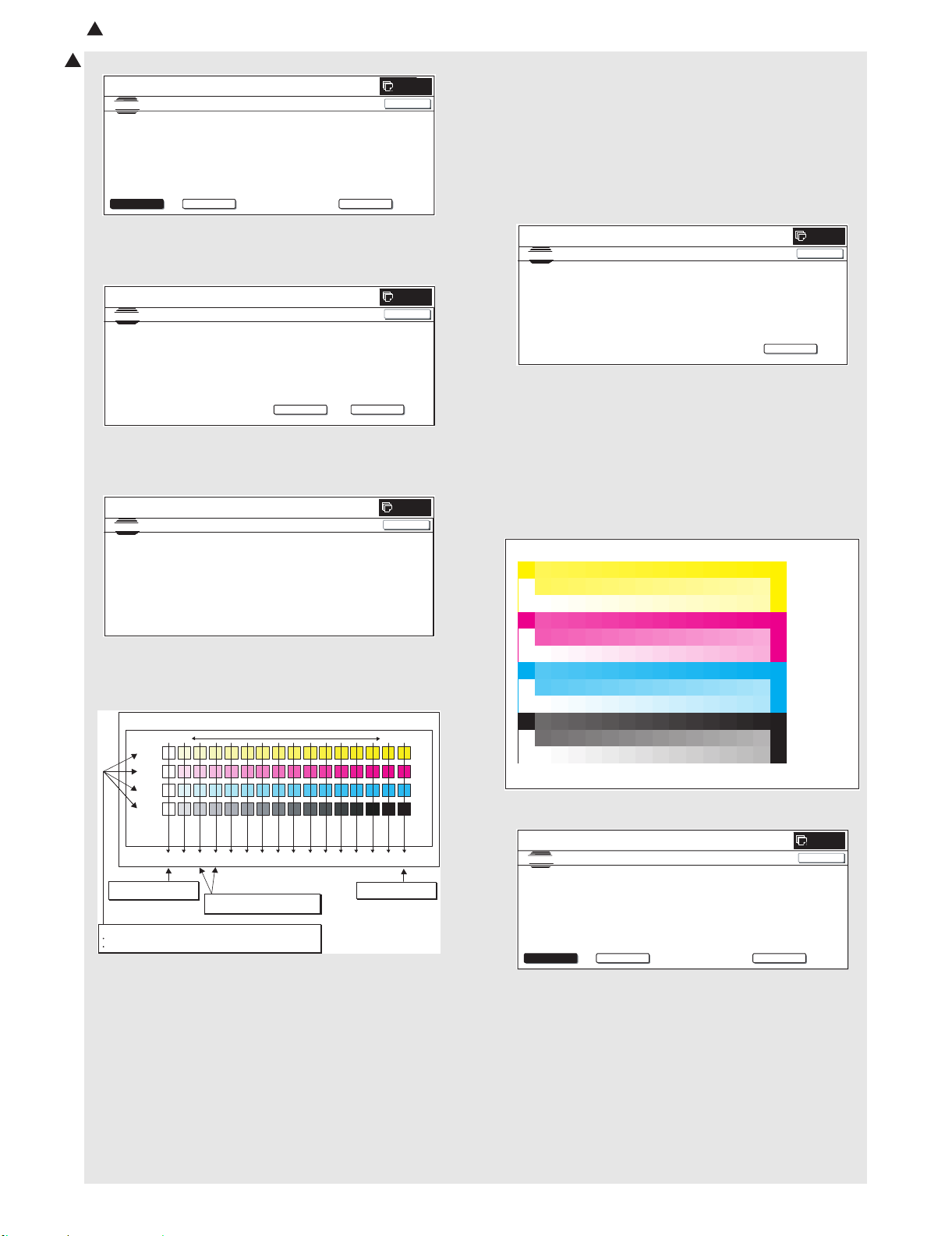
6) Check the color balance and density.
Check to insure that the printed color balance check patch
image is within the following specifications.
Patch A of each of Y, M,
C, and BK are not copied.
3) Patch for each of C, M, Y, BK
The patch density is identical between patches or not reversed.
The patch density is changed gradually.
The print density must be changed gradually from the lighter
level to the darker level. The density changing direction must
not be reversed.
The density level of each color must be almost at the same
level.
Patch B may not be copied.
Patch A must not be copied.
Fig. 1 PG image
Y
M
C
Bk
AB C DE FGHI J KL MNO
2) Patch C or D of each of Y, C, M,
and BK is very slightly copied.
High densityLow density
Max
1) The max. density
section is not blurred.
4) Press [FACTORY] key, and press [EXECUTE] key.
SIMULATIONNO.67-24
TEST
PRINTER E N G INE HALFTON E AUTO A D JU STMEN T MODE
PLEASE SELECT THEMODE(FACTORY) OR (SE RVICE ) AND PLACE
THEPRINTEDTESTPATCH ON DOCUMENT GLAS S THEN PRESS [ EXECUTE].
,
㪁
LIGHTAREA AT LEFTSIDEONDOCUMENTGLASS.
FACTORY
SERVICE
EXECUTE
The copy color balance adjustment is automatically executed
and prints the color balance check patch image. Wait until the
operation panel shown in the next procedure is displayed.
0
CLOSE
MX-3500N/4500N, MX-3501N/4501N 1 – 13
Page 17
: Nov. 15 2006
4
5) Press [OK] key.
4
0
CLOSE
SIMULATIONNO.67-24
TEST
PRINTER ENGINE HALFTONE AUTO ADJUSTMENT MODE
CONFIRM TH EADJUSTEDPATCH AND PRESS [OK] TO REGISTER THIS PATCH DATA
PRESS [REPEAT] TO CONTINUE TH IS PROCEDUR E.
REPEAT
CLOSE
OK
NOTE:
Do not cancel the simulation until "PLEASE QUIT THIS
MODE" is displayed.
0
SIMULATIONNO.67-24
TEST
PRINTER ENGINE HALFTON E AUTO ADJUSTMENT MODE
COMPLETED THIS PROCEDURE.
PLEASE QUIT THIS MODE.
CLOSE
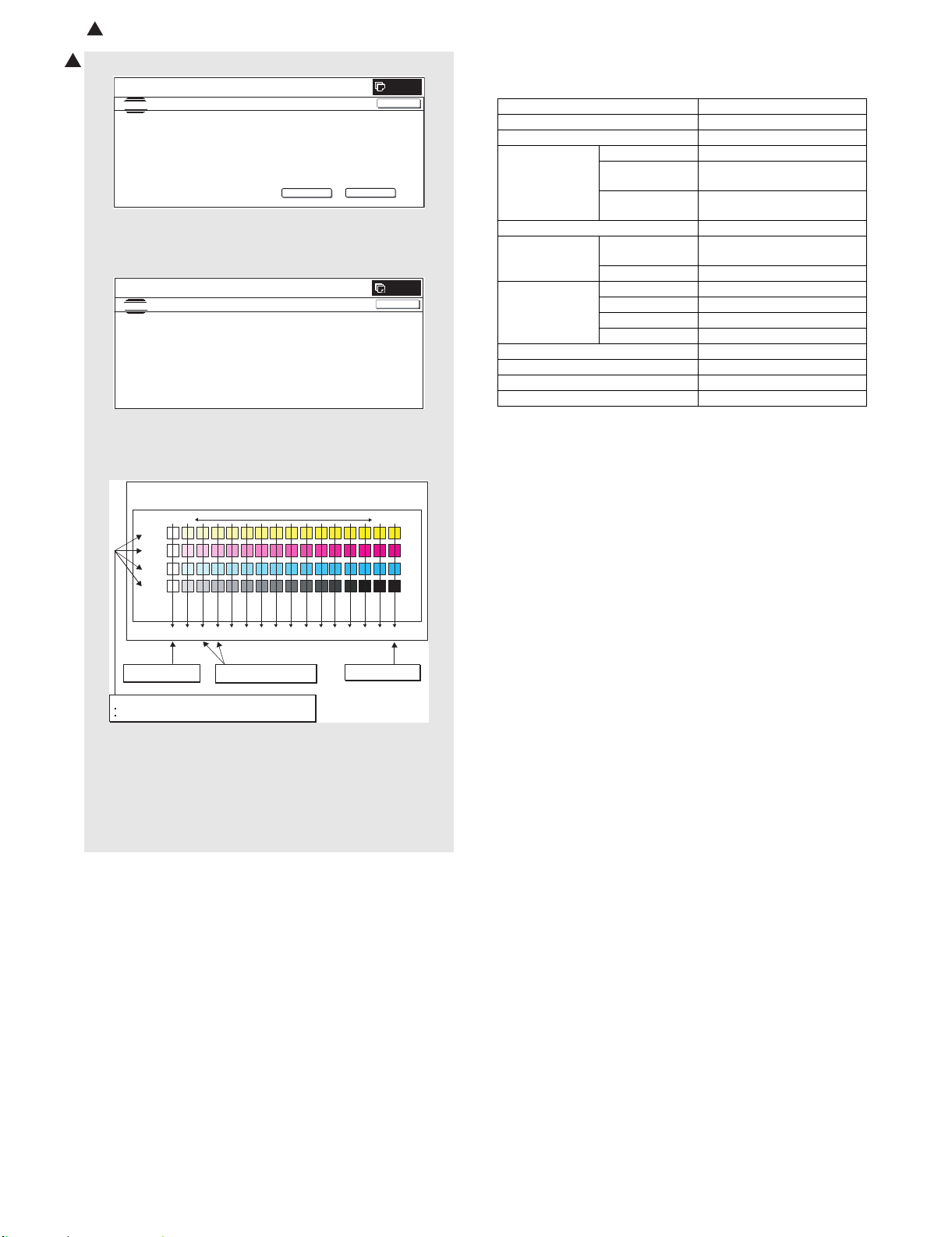
6) Check the color balance and density.
Check to insure that the printed color balance check patch
image is within the following specifications.
PRINTER CALIBRATION
Y
M
C
Bk
AB C DEFGHI J KL MNO
Patch A of Y, M, C, and
BK are not copied.
3) Patch for each of C, M, Y, BK
The patch density is identical between patches or not reversed.
The patch density is changed gradually.
Fig. 1 PG image
2) Patch C or D of each of Y, C,
M, Bk is very slightly copied.
High densityLow density
Max
1) Max. density section
is not blurred.
The print density must be changed gradually from the lighter
level to the darker level. The density changing direction must
not be reversed.
The density level of each color must be almost at the same
level.
Patch B may not be copied.
Patch A must not be copied.
c. When the PCL mode is supported:
Execute SIM 64-5 to print the print test pattern.
Set each set value to the default and press [EXECUTE] key. The
print test pattern is printed.
The print density must be changed gradually from the lighter level
to the darker level. The density changing direction must not be
reversed. The density level of each color must be almost at the
same level.
d. When the PCL mode is not supported: (In the case of GDI
model)
Use SIM 67-25 to print the color balance adjustment sheet and
compare each process (CMY) black patch color balance and the
black patch to check the color balance.
The print density must be changed gradually from the lighter level
to the darker level. The density changing direction must not be
reversed.
The density level of each color must be almost at the same level.
Patch B may not be copied.
Patch A must not be copied.
M. Function and operation check
Check that the following operations are normal.
Key-in (operation panel)
Display (operation panel)
Paper feed
operation
Paper size detection
Originals size
detection
RSPF operation/
two sided copy
Bookbinding operation With the finisher installed
Stapling operation With the finisher installed
Grouping operation With the finisher installed
Sorting operation With the finisher installed
Check items Equipped condition
Hand feed
Main unit paper
tray
Desk unit paper
With the desk unit installed
feed tray
Original table
mode
RSPF mode
S-S mode
D-S mode
S-D mode
D-D mode
N. Setup and adjustment data recording
Print the various setup data and the adjustment data (list) with
SIM22-6 and keep the data.
• In case of a memory trouble, if the data are not kept, all the
adjustments must be made again.
• If the data are kept, the setup values and the adjustment values
can be entered without adjustments, shortening the servicing
time.
O. Necessary works before moving the machine
1) If the following options are installed, remove all of them from
the machine.
• Saddle stitch finisher
• Large capacity tray
2) Remove the following consumable parts from the machine.
• Paper
• Toner cartridge
• Development cartridge
3) Lock the following sections.
• Scanner (Optical section)
• Paper cassette lift plate
NOTE: Since the hard disk drive is built in the machine, use care
not to exert vibrations or shocks to the machine when in
transit.
MX-3500N/4500N, MX-3501N/4501N 1 – 14
Page 18
MX3500N
[2] MX-DEX3/DEX4
1. Unpacking
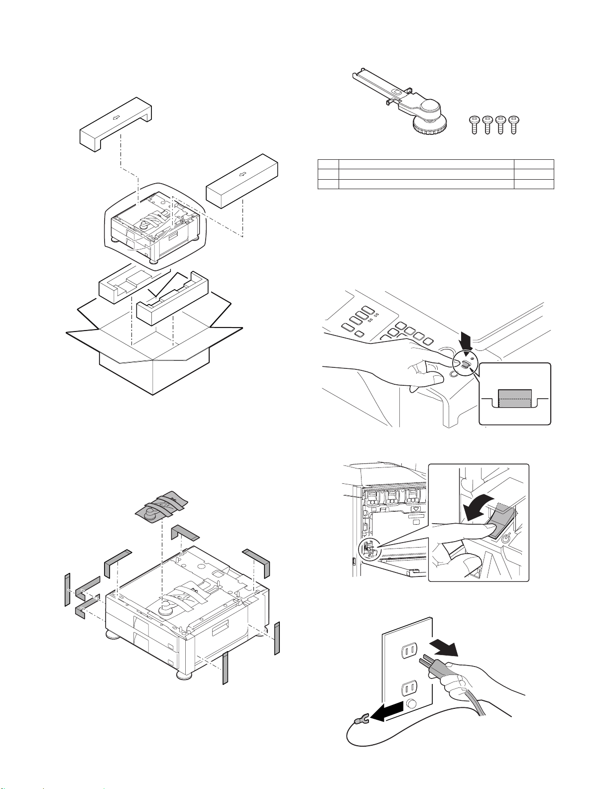
A. Removal of the desk unit
C. Check the packed items
Service Manual
1) Check that all the items are included in the package.
12
No. Names of bundles Quantity
1 Right adjuster 1
2 Fixing screws (M4 x 8) 4
2. Installation
<Note before installation>
* Before starting installation, check to insure that the data lamp on
the operation panel does not light up or blink.
A. Turn off the power of the main unit
1) Turn OFF the power switch on the operation panel.
B. Removal of the fixing material and packing
parts
* If the connector is removed first, it may be pinched in the install-
ing procedures. Therefore, keep it packed when unpacking the
package, and unpack it when connecting the connector to the
machine.
1) Remove the fixing material and packing parts.
OFF
OFF
2) Open the front cabinet.
Turn OFF the power switch in the front cabinet of the main unit.
OFF
3) Disconnect the power plug of the main unit from the power out-
let, and remove the earth cord.
MX3500N MX-DEX3/DEX4 2 – 1
Page 19
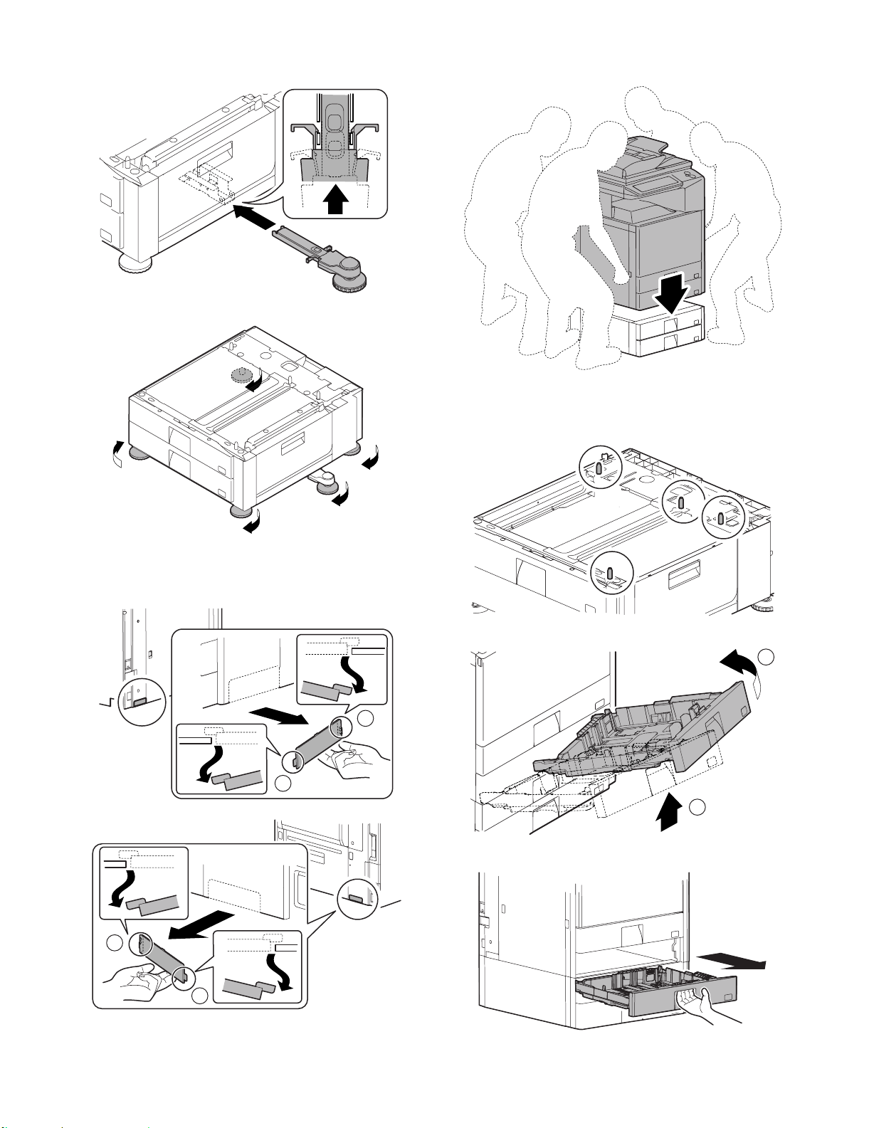
B. Installation of the adjuster
1) Install the right adjuster (package part No. 1) to the desk unit.
2) Turn each adjuster to fix the desk unit.
2) Put the main unit on the desk unit.
* Use man power of four persons or more to lift the main unit.
* Place the main unit on the desk unit slowly by fitting the
external lines. Check to insure that the positioning pin on the
top of the desk unit is securely engaged in the positioning
groove of the main unit.
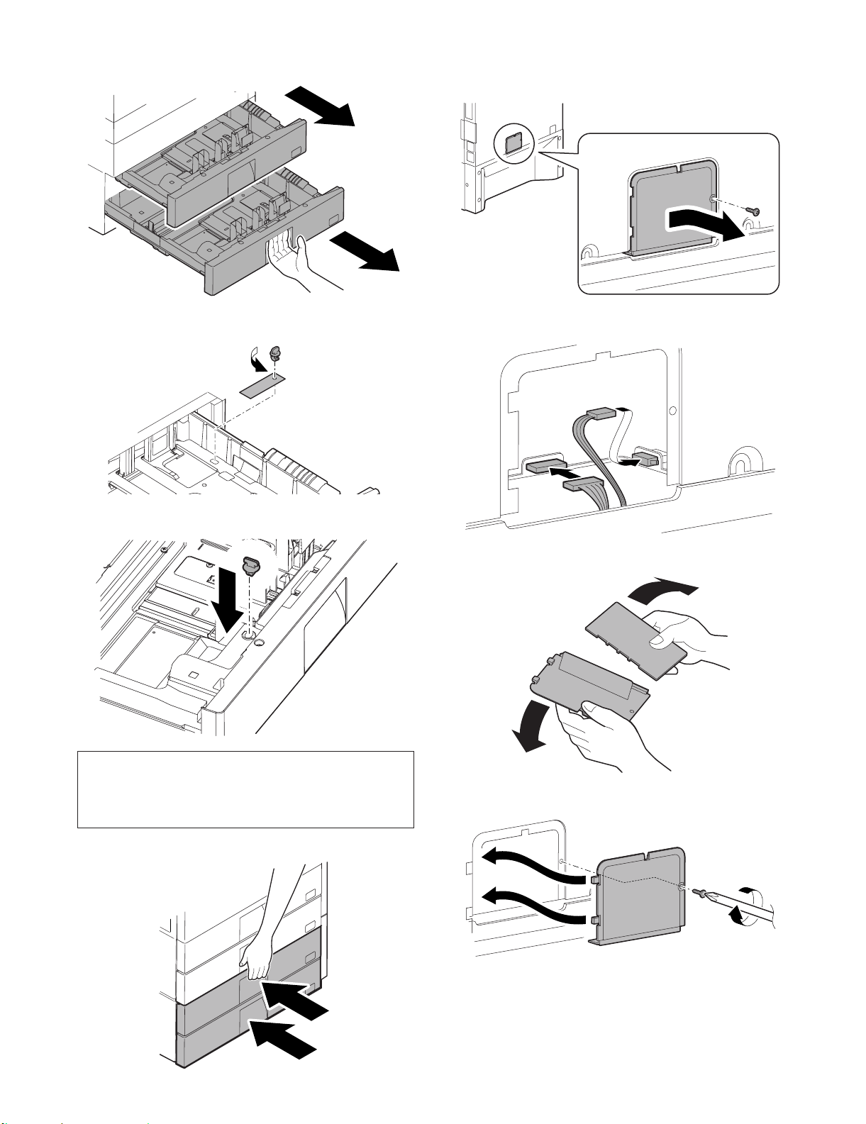
C. Connection of the main unit and the desk unit
1) Remove the connection plate covers of the both sides of the
main unit.
2
1
2
3) Remove the No. 2 paper feed tray.
2
1
4) Pull out the No. 3 paper feed tray until it stops.
1
MX3500N MX-DEX3/DEX4 2 – 2
Page 20
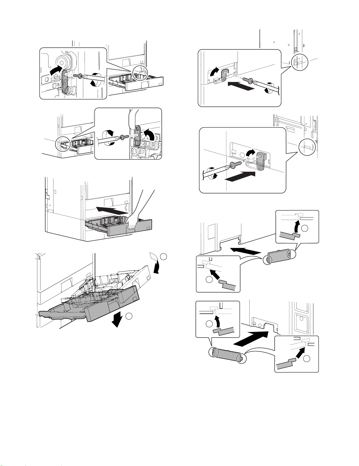
5) Lift the connection plates on the right and left of the main unit
front side, and fix them with the fixing screws (package part
No. 2).
6) Replace the No. 3 and No. 2 trays to the original positions.
7) Lift the connection plates, and fix them with the fixing screws.
8) Install the connection plate covers.
2
1
1
2
2
1
MX3500N MX-DEX3/DEX4 2 – 3
Page 21
D. Release the lock
1) Pull out each tray.
E. Connector connection
1) Remove the screw from the back of the main unit. Remove the
connector cover.
2) Turn and remove the fixing material, and remove the caution
sheet.
3) Attach the removed fixing material to the position shown in the
figure for storage.
2) Connect the connector.
3) Split the removed connector cover along the perforated line.
NOTE:
Before turning on the power, check to insure that the fixing
material of the tray is disengaged. If the power is turned on
without disengaging the fixing material, a trouble may be
resulted.
4) Close the cassette which was pulled out.
MX3500N MX-DEX3/DEX4 2 – 4
4) Install the connector cover and fix it with a screw.
Page 22
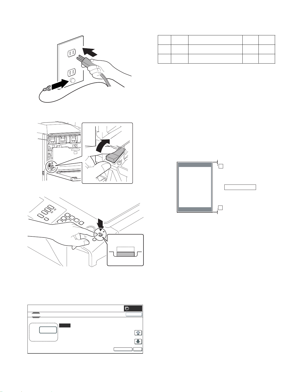
F. Turn on the power of the main unit
A
1) Connect the earth cord, and insert the power plug of the main
unit into the power outlet.
2) This screen allows you to configure the print off-center adjustment value for each paper feed tray.
<Detailed Description>
2) Open the front cabinet.
Turn ON the power switch in the front cabinet of the main unit.
ON
Item Display Description
E CS3 Print off-center adjustment value
(tray 3)
F CS4 Print off-center adjustment value
(tray 4)
Setting
range
1 to 99 50
1 to 99 50
Default
3) On the touch panel, press [↓] to select "E: 50 : CS3" or "F:
50 : CS4."
4) Enter the desired adjustment value through the numeric keypad.
(This value, which defaults to 50, can be adjusted within the
range of 1 to 99).
• Reducing the adjustment value by 1 causes the main scan/
print position to shift by 0.1 mm toward the rear.
• Increasing the adjustment value by 1 causes the main scan/
print position to shift by 0.1 mm toward the front.
5) After entering the adjustment value, press the [EXECUTE] key
on the touch panel to start printing and save the setting.
6) Check that the adjustment pattern image is printed in the correct position.
Measure the dimensions of the void areas on the front- and
rear-frame sides of the adjustment pattern image, and make
sure that the following conditions are met:
A
3) Turn ON the power switch on the operation panel.
ON
ON
* For setting the tray size, refer to "Tray size setting" (1-9).
G. Off-center adjustment
(1) Adjustment with the simulation
1) Run SIM50-10 using the keypad on the main unit.
The following screen appears:
SIMULATION NO.50-10
TEST
PAPER CENTER OFFSET SETUP
100
:
[64 -140]
A:100
B :50
C: 50 CS1
D: 50 CS
BK-MAG
;
MTF
;
;
; 2
CLOSE
+
A-B = 0 3.0mm
-
B
No adjustment is needed if A - B = 0 ±3.0 mm.
If the above condition is not met, do the following:
7) Change the adjustment value.
(Enter a new adjustment value and press the [OK] key).
Changing the adjustment value by 1 shifts the position by
approximately 0.1 mm.
Repeat steps 4) to 6) until the condition shown in step 6) is sat-
isfied.
8) After you have completed the adjustment, exit from Simulation
mode by pressing the [CA] key.
0
EXECUTE
OK
MX3500N MX-DEX3/DEX4 2 – 5
Page 23

MX3500N
[3] MX-TRX2
1. Unpacking
A. Removal of the exit tray unit
B. Check the packed items
1) Check that all the items are included in the package.
2) Open the front cabinet.
Service Manual
Turn OFF the power switch in the front cabinet of the main unit.
OFF
3) Remove the earth cord and disconnect the power plug of the
main unit from the power outlet.
12
No. Packed part names Quantity
1 Exit roller unit 1
2 Full detection actuator 1
2. Installation
<Note before installation>
* Before starting installation, check to insure that the data lamp on
the operation panel does not light up or blink.
A. Turn off the power of the main unit
1) Turn OFF the power switch on the operation panel.
OFF
OFF
B. Installation of the exit roller unit
1) Open the right door.
2
1
2) Remove the screw, and remove the connector cover.
MX3500N MX-TRX2 3 – 1
Page 24

3) Remove the screw. Disengage the engagement in the front
ON
ON
side then in the rear side, and remove the paper exit cover.
4
3
4) Connect the connector, and install the exit roller unit (package
part No. 1). Use the screw which was removed in step 3) and
fix the unit.
1
2
C. Turn on the power of the main unit.
1) Connect the earth cord, and insert the power plug of the main
unit into the power outlet.
2) Open the front cabinet.
Turn ON the power switch in the front cabinet of the main unit.
ON
5) Install the connector cover, and fix it with the screw.
6) Install the exit tray unit (A) and the full detection actuator (B)
(package part No. 2).
* Be careful of the installing direction of the full detection actu-
ator.
B
B
3) Turn ON the power switch on the operation panel.
D. Tray setting
Use SIM26-1 to set the tray YES/NO.
A
MX3500N MX-TRX2 3 – 2
Page 25

MX3500N
[4] MX-LCX1
1. Unpacking
A. Removal of the large capacity tray unit
3) Remove the paper feed desk fixing screw.
Service Manual
NOTE:
Before turning on the power, check to insure that the fixing
screw of the tray is removed. If the power is turned on
without removing the fixing screw, a trouble may be
resulted.
C. Check the packed items
1) Check that all the items are included in the package.
B. Removal of the fixing material and packing
parts
1) Remove the fixing material.
2) Remove the fixing material and the packing parts.
1
34
25
No. Names of bundles Quantity
1 Mounting plate upper 2
2 Connection unit 1
3 Fixing screw A (Hexagon with seat, S-tight, M4 x 35) 4
4 Fixing screw B (Hexagon with seat, S-tight, M4 x 12) 2
5 Fixing screw C (screw 4 x 8 cup) 1
2. Installation
<Note before installation>
* Before starting installation, check to insure that the data lamp on
the operation panel does not light up or blink.
A. Turn off the power of the main unit
1) Turn OFF the power switch on the operation panel.
MX3500N MX-LCX1 4 – 1
OFF
OFF
Page 26

2) Open the front cabinet.
1
2
Turn OFF the power switch in the front cabinet of the main unit.
OFF
3) Disengage the pawl, and remove the right adjuster.
1 1
2
3) Remove the earth cord and disconnect the power plug of the
main unit from the power outlet.
B. Connection of the main unit and the large
capacity tray unit
1) Install the mounting plate upper (package part No. 1) to the
right side of the main unit with the fixing screw A (package part
No. 3).
* When installing, put the rubber section of the mounting plate
upper on the lower side.
4) Remove the screw cap, and remove the screw.
5) Remove the cover.
2) Remove the right door cover from the machine.
1
2
3
6) Temporarily fix the fixing screw B (package part No. 4) midway.
3
MX3500N MX-LCX1 4 – 2
Page 27

NOTE:
If the screw is loosened or removed when servicing, be sure
to execute "C. Height adjustment of the large capacity tray
unit" after completion of servicing.
: Jun. 15 2006
2
7) Insert the temporarily fixed screw B into the key hole in the
connection unit (package part No. 2), and temporarily fix the
connection unit.
1
2
8) Fix the other fixing screw B (package part No. 4), and tighten
the temporarily fixed screw B securely.
2
2) Check to insure that the height adjustment check rib of the
large capacity tray unit and the axis line of the mounting plate
upper mounted to the main unit are in the same line.
1
9) While lifting the section marked with {, insert the connection
2
unit into the large capacity tray unit, and fix the fixing screw C
(package part No. 5) at the mark A on the connection unit.
1
2
C. Height adjustment of the large capacity tray
unit
1) Put the large capacity tray unit closer to the main unit.
[Shift to the left] [Shift to the right]
3) If the height adjustment is not required, insert the large capacity tray unit further more.
If the height adjustment is required, perform the adjustment
procedures from 4).
4) Loosen the adjustment screw on the F side.
* Use the adjustment screw on the front side for the adjust-
ment. Do not touch the screw on the rear side.
MX3500N MX-LCX1 4 – 3
Page 28

5) In the case of a shift to the right, press the front upper section
and fit the height adjustment check rib so that it is in the same
line with the axis line of the mounting plate upper. Insert the
large capacity tray unit into the main unit.
6) In the case of a shift to the left, lift the grip so that the height
adjustment check rib is in the same line with the axis line of the
mounting plate upper, and insert the large capacity tray unit.
2) Connect the connector, and tighten the screw.
E. Paper size switch
(1) Paper size switch from A4 to LT
Since the factory setting of the paper size is A4, if paper size switch
is required, perform the following procedures.
1) Slowly pull out the tray until it stops.
7) Tighten the loosened screw.
D. Connector connection
1) Remove the screw, and remove the connector cover.
2) Loosen the stopper fixing screw (1 pc) on the right lower side
of the tray so that the stopper does not function.
3) Pull out the tray again until it stops.
MX3500N MX-LCX1 4 – 4
Page 29

a. Side plate size switch
A4 LT
1) Remove four fixing screws (blue screws) which are fixing the
upper and the lower sections of the side plate F and the side
plate R.
F side R side
2) Loosen the fixing screw (flat screw 1pc) of the auxiliary guide.
3) Set the mark position ( ) of the auxiliary guide and the cassette R to the size from A4 to LT, and fix with the fixing screw
(flat screw).
2) Adjust the mark position of the tray and the side plates in the
lower section of the side plates F/R according to the desired
size. Also adjust the upper section according to the desired
size, and fix with the four fixing screws (blue screws).
F side R side
At that time, set the mark position ( ) of the auxiliary guide
and the cassette R to the same scale of the mark position ( )
of the side plate R and the size guide adjustment plate confirmed in procedure 1). (If the scale of the size guide adjustment plate is at the center, set it to the center. If the size guide
adjustment plate is in 1mm in the front side, set it in 1mm in the
front side.)
c. Rear edge shaft switch
1) Remove the rear edge shift fixing screw (blue screw) which is
fixing the shaft to the right side inside the tray, and remove the
rear edge shaft.
2) Tighten the removed rear edge shaft with the fixing screw
(blue), and store it in the storage space inside the front cabinet.
b. Auxiliary guide size switch
1) When switching the size of the side plate R, check to confirm
the mark position ( ) of the side plate R and the size guide
adjustment plate.
MX3500N MX-LCX1 4 – 5
Page 30

3) Slightly push the tray, restore the stopper to the original position, and fix the fixing screw.
2) Loosen the stopper fixing screw (1 pc) on the right lower side
of the tray so that the stopper does not function.
At that time, check to insure that the stopper pawl is engaged
with the stopper reception of the large capacity tray unit.
4) Slowly insert the tray to the original position.
3) Pull out the tray again until it stops.
a. Side plate size switch
1) Remove four fixing screws (blue screws) which are fixing the
upper and the lower sections of the side plate F and the side
plate R.
F side R side
(2) Paper size switch from A4 to B5
Since the factory setting of the paper size is A4, if paper size switch
is required, perform the following procedures.
1) Slowly pull out the tray until it stops.
MX3500N MX-LCX1 4 – 6
2) Adjust the mark position of the tray and the side plates in the
lower section of the side plates F/R according to the desired
size. Also adjust the upper section according to the desired
size, and fix with the four fixing screws (blue screws).
Page 31

F side R side
b. Auxiliary guide size switch
* Since the auxiliary guide setting is not required, fix the auxiliary
guide to either of A4 or LT. (To prevent against missing of the
part)
c. Rear edge shaft switch
1) Remove the rear edge shift fixing screw (blue screw) which is
fixing the shaft to the right side inside the tray, and remove the
rear edge shaft.
3) Slightly push the tray, restore the stopper to the original position, and fix the fixing screw.
At that time, check to insure that the stopper pawl is engaged
with the stopper reception of the large capacity tray unit.
2) Insert the removed rear edge shaft into the mounting hole in
the paper feed desk as shown in the figure below. Fix the
upper section with the fixing screw (blue screw) which was
removed previously.
NOTE:
When the rear edge shaft is switched to B5, check to confirm
that the side plates F/R are already set to B5. If the side plates
F/R are not set to B5, the rear edge shaft cannot be switched
to B5.
4) Slowly insert the tray to the original position.
F. Turn on the power of the main unit
1) Connect the earth cord, and insert the power plug of the main
unit into the power outlet.
MX3500N MX-LCX1 4 – 7
Page 32

2) Open the front cabinet.
Turn ON the power switch in the front cabinet of the main unit.
6) Check that the adjustment pattern image is printed in the correct position.
Measure the dimensions of the void areas on the front- and
rear-frame sides of the adjustment pattern image, and make
sure that the following conditions are met:
ON
3) Turn ON the power switch on the operation panel.
ON
ON
G. Size setting
Execute SIM 26-2 "Size setting" with the key operations of the main
unit.
1) The size selection menu of the large capacity tray is displayed
on the operation message display.
2) Select a size button to be set on the message screen.
H. Off-center adjustment
(1) Adjustment with the simulation
1) Run SIM 50-10 using the keypad on the main unit.
The following screen appears.
A
+
A-B = 0 3.0mm
-
B
No adjustment is needed if A - B = 0 ± 3.0 mm.
If the above condition is not met, do the following:
7) Change the adjustment value.
(Enter a new adjustment value and press the [OK] key).
Changing the adjustment value by 1 shifts the position by
approximately 0.1 mm.
Repeat steps 4) to 6) until the condition shown in step 6) is sat-
isfied.
8) After you have completed the adjustment, exit from simulation
mode by pressing the [CA] key.
(2) Mechanical adjustment
Since the off-center adjustment is performed when shipping, there
is basically no need to perform this adjustment. If the center is
shifted, however, the simulation is normally used. If the shift is not
removed, perform the following adjustment procedures.
1) Slowly pull out the tray until it stops.
0
SIMULATION NO.50-10
TEST
PAPER CENTER OFFSET SETUP
100
A:
= 64-140 ]
A:100
; BK-MAG
B:50
; MTF
C:50 ; CS1
D:50 ; CS2
2) This screen allows you to configure the print off-center adjustment value for each paper feed tray.
3) On the touch panel, press [↓] to select "G: 50 :LCC."
4) Enter the desired adjustment value through the numeric keypad.
(This value, which defaults to 50, can be adjusted within the
range of 1 to 99).
• Reducing the adjustment value by 1 causes the main scan/
print position to shift by 0.1 mm toward the rear.
• Increasing the adjustment value by 1 causes the main scan/
print position to shift by 0.1 mm toward the front.
5) After entering the adjustment value, press the [EXECUTE] key
on the touch panel to start printing and save the setting.
CLOSE
EXECUTE
OK
MX3500N MX-LCX1 4 – 8
2) Loosen the stopper fixing screw (1 pc) on the right lower side
of the tray so that the stopper does not function.
Page 33

3) Pull out the tray again until it stops.
B
Rside
Fside
a. When the shift is in the front side
To adjust the print line in the direction A from the paper center as
shown in the figure:
1) Loosen two fixing screws (red screws) of the front/rear size
guide adjustment plate, and move the size guide adjustment
plate in the direction A (R side) by the shift amount, and tighten
the red fixing screws (2 for each). Move the auxiliary guide in
the direction A by the same size.
Rside
b. When the shift is in the rear side
To adjust the print line in the direction B from the paper center as
shown in the figure:
1) Loosen two fixing screws (red screws) of the front/rear size
guide adjustment plate, and move the size guide adjustment
plate in the direction B (F side) by the shift amount, and tighten
the red fixing screws (2 for each). Restore the stopper to the
original position, and fix it with the fixing screws. Move the auxiliary guide in the direction B by the same size.
Check to insure that the stopper pawl is engaged with the stopper reception of the large capacity tray.
A
Fside
Slightly push the tray, restore the stopper to the original position, and fix the fixing screw.
Check to insure that the stopper pawl is engaged with the stopper reception of the large capacity tray.
2) Slowly insert the tray to the original position.
Then make a copy to check to insure that there is no more
shift. Repeat the procedures until there is no shift.
2) Slowly insert the tray to the original position.
Then make a copy to check to insure that there is no more
shift. Repeat the procedures until there is no shift.
MX3500N MX-LCX1 4 – 9
Page 34

10 11 12
1
4
8 9
2
567
3
No. Packed part names Quantity
1 Finisher fixing plate 1
2 Front slide rail 1
3 Dummy punch unit 1
4 Front open/close cover 1
5 Punch cover 1
6 Left front cover 1
7 Finisher slide stopper 8
8 Fixing screw 1
9 Resin clip 1
10 Coin screw 1
11 Staple position label (For scanner) 1
12 Staple position label (For RSPF/DSPF) 1
MX3500N
[5] MX-FNX1
1. Unpacking
A. Removal of the inner finisher
B. Removal of the fixing tape and protection
Service Manual
material
1) Remove the fixing tape and protection material.
C. Check the packed items
1) Check that all the items are included in the package.
* When removing the inner finisher, lift it as shown in the table
below.
MX3500N MX-FNX1 5 – 1
Page 35

2. Installation
<Note before installation>
* Before starting installation, check to insure that the data lamp on
the operation panel does not light up or blink.
A. Turn off the power of the main unit
1) Turn OFF the power switch on the operation panel.
OFF
OFF
2) Open the front cabinet.
Turn OFF the power switch in the front cabinet of the main unit.
OFF
B. Removal of the paper holding arm unit
1) Push up the section A to disengage the pawl, and remove the
paper holding arm and the paper holding arm holder together
as a unit.
* Be careful to remove both of the paper holding arm (which is
easily removed alone) and the paper holding arm holder.
2
1
A
C. Installation of the inner finisher
1) Open the front cover.
3) Remove the earth cord and disconnect the power plug of the
main unit from the power outlet.
2) Remove two screws, and remove the front cabinet upper.
MX3500N MX-FNX1 5 – 2
Page 36

3) Disengage two pawls, and remove the paper exit tray cover.
4) Remove four screws, and remove the paper exit tray.
* When removing the paper exit tray, there is no need to
remove the screws in the section (A).
A
5) Remove the paper exit full detection actuator.
8) Install the front slide rail (A) (package part No. 2) with the three
fixing screws (package part No. 8), and install the left front
cover (B) (package part No. 6) with one fixing screw (package
part No. 8).
A
B
9) Fix the dummy punch unit (package part No. 3) with the fixing
screw (package part No. 8).
6) Engage the projection on the main unit frame with the hole in
the finisher fixing plate (package part No. 1).
7) Fix the right cover plate with the fixing screw (package part No.
8).
10) Check to insure that the slide roller is in the rail groove, and
insert the inner finisher.
11) Fix the rear slide rail with the fixing screw (package part No. 8).
* Fix the side plate of the paper exit shifter with the fixing
guide.
MX3500N MX-FNX1 5 – 3
Page 37

12) After pushing the intermediate rail of accuride, insert the finisher slide stopper (package part No. 7) between the rear slide
rail and the accuride.
Fix it with the coin screw (package part No. 10).
13) Install the front open/close cover (package part No. 4) to the
front rail stay rotating shaft, and fix it with the resin clip (package part No. 9).
2
1
D. Connector connection
1) Remove the protection material and fixing tape.
1
2
2) Remove the screw, and remove the connector cover.
14) Fix the punch cover (package part No. 5) together with the
band (metal fixture) with the fixing screw (package part No. 8).
1
2
15) Install the front cabinet upper with two screws.
3) Connect the finisher connector with the main unit connector,
and tighten with a screw.
E. Staple position label attachment
1) Attach the label to the position indicated in the figure.
[For scanner] (package part No. 11)
Corner R end fitting
Label attachment
reference
* Corner of the
"upper cabinet rear"
Corner R end fitting
MX3500N MX-FNX1 5 – 4
Page 38

[For RSPF/DSPF] (package part No. 12)
ON
ON
DSPF
CAUTION
When streaksappear on copy or scan
images, openthe automatic document
feed unitand clean the document scan
section withthe glass cleaner (accessory).
Documentscan section
RSPF
3) Turn ON the power switch on the operation panel.
F. Turn on the power of the main unit
1) Connect the earth cord, and insert the power plug of the main
unit into the power outlet.
2) Open the front cabinet.
Turn ON the power switch in the front cabinet of the main unit.
ON
MX3500N MX-FNX1 5 – 5
Page 39

OFF
OFF
MX3500N
[6] MX-PNX1A/B/C/D
1. Unpacking
A. Removal of the punch unit
C. Check the packed items
Service Manual
1) Check that all the items are included in the package.
1
No. Packed part names Quantity
1 Punch position label (For scanner) 1
2 Punch position label (For RSPF/DSPF) 1
2
2. Installation
* When the punch unit is installed together with installation of
the MX-FNX1 (inner finisher), first install the inner finisher,
and then install the punch unit.
<Note before installation>
* Before starting installation, check to insure that the data lamp on
the operation panel does not light up or blink.
* Do not install the punch unit first because doing so would cause
interference between the inner finisher slide rail and the punch
unit drawer connector (possibly resulting in failure) when you
attempt to install the inner finisher.
B. Removal of the fixing tape
1) Remove the fixing tape.
A. Turn off the power of the main unit
1) Turn OFF the power switch on the operation panel.
MX3500N MX-PNX1A/B/C/D 6 – 1
Page 40

2) Open the front cabinet.
Turn OFF the power switch in the front cabinet of the main unit.
OFF
3) Remove the earth cord and disconnect the power plug of the
main unit from the power outlet.
3) Remove the coin screw, and remove the finisher slide stopper.
4) Slide the inner finisher further more.
5) Remove two screws, and remove the front cabinet upper.
B. Installation of the punch unit
1) Open the front cabinet.
2) Open the front lid, and slide the inner finisher.
2
6) Remove the screw, and remove the band and the punch cover.
1
MX3500N MX-PNX1A/B/C/D 6 – 2
Page 41

7) Remove the screw, and remove the dummy punch unit.
11) Remove the dust box.
8) Fix the punch unit with a screw.
* When installing the punch unit, be careful not to bump it
against the drawer connector.
* Fit the positioning pin and insert it.
3
2
1
9) Make positioning with the dove (A) and fix the punch unit with
the screw which was fixing the dummy punch unit.
A
12) Fix the punch cover and the band together with one screw.
1
2
13) Insert the dust box.
10) Cut the lid of the punch cover with nippers.
14) Install the front cabinet upper part using the two screws
removed in step 5).
A
15) Insert the finisher slide stopper between the slide rail and the
accuride, and fix it with the coin screw.
MX3500N MX-PNX1A/B/C/D 6 – 3
Page 42

16) Slide the inner finisher to the original position, and close the
front cover.
1
2
C. Punch position label attachment
1) Attach the label to the position indicated in the figure.
[For scanner] (package part No. 1)
D. Turn on the power of the main unit
1) Connect the earth cord, and insert the power plug of the main
unit into the power outlet.
2) Open the front cabinet.
Turn ON the power switch in the front cabinet of the main unit.
No clearance
Second label
Corner R end fitting
Label attachment reference
*Cornerofthe
"upper cabinet rear"
First label
Corner R end fitting
[For RSPF] (package part No. 2)
DSPF
R2.5 connection line
ON
3) Turn ON the power switch on the operation panel.
ON
ON
Edge line R 2.5
RSPF
Cleaning of the document scan section
CAUTION
When streaksappear on copy or scan
images, openthe automatic document
feed unitand clean the document scan
section withthe glass cleaner (accessory).
Documentscan section
MX3500N MX-PNX1A/B/C/D 6 – 4
Page 43

12 3
456
78
No. Packed part names Quantity
1 Right cover plate 1
2 Interface left cabinet 1
3 Reverse tray 1
4 Fixing screw A 6
5 Fixing screw B 1
6 Ornamental screw 1
7 Reverse detection actuator 1
8 Stopper 1
OFF
OFF
MX3500N
[7] MX-RBX1, MX-FNX2
1. Unpacking the MX-RBX1
A. Removal of the interface pass unit
B. Removal of the fixing tape
1) Remove the fixing tape.
C. Check the packed items
Service Manual
1) Check that all the items are included in the package.
2. Installing the MX-RBX1
<Note before installation>
* Before starting installation, check to insure that the data lamp on
the operation panel does not light up or blink.
A. Turn off the power of the main unit
1) Turn OFF the power switch on the operation panel.
2) Open the front cabinet.
Turn OFF the power switch in the front cabinet of the main unit.
OFF
MX3500N MX-RBX1, MX-FNX2 7 – 1
Page 44

3) Remove the earth cord and disconnect the power plug of the
main unit from the power outlet.
B. Removal of the paper holding arm unit
1) Push up the section A to disengage the pawl, and remove the
paper holding arm and the paper holding arm holder together
as a unit.
* Be careful to remove both of the paper holding arm (which is
easily removed alone) and the paper holding arm holder.
2
2) Disengage the pawls, and remove the paper exit tray cover.
3) Remove the screws, and remove the paper exit tray.
4) Remove the paper exit full detection actuator (A), and install
the reverse detection actuator (B) (package part No. 7).
* Be careful of the installing direction of the reverse detection
actuator.
1
A
C. Installation of the interface pass unit
1) Open the front cabinet. Remove the screws, and remove the
front cabinet upper.
1
A
B
5) Engage the projection of the main unit frame with the hole in
the right cover plate (package part No. 1), and install the right
cover plate and fix it with the fixing screw A (package part No.
4).
2
B
* Be sure to clamp and fix the paper exit tray shifter side plate
with the fixing guide.
MX3500N MX-RBX1, MX-FNX2 7 – 2
Page 45

6) Insert the rib of the interface left cabinet (package part No. 2)
into the slit on the lower surface of the scanner left cabinet.
Install the interface left cabinet with the fixing screw A (package part No. 4) of the paper exit tray which was removed in
procedure 4).
7) Insert the reverse tray (package part No. 3) along the groove in
the interface left cabinet and the top surface of the right cover
plate.
* When inserting the reverse tray, check to insure that the
switch guide of the reverse tray is up.
9) Install the front cabinet upper, and fix with the screws.
10) Fix the stopper (package part No. 8) with the fixing screw B
(package part No. 5).
8) Fix the reverse tray with the ornamental screw (package part
No. 6).
11) Insert the interface pass unit along the guide rail.
12) Fix the interface pass disconnection preventing lever with the
fixing screw A (package part No. 4).
13) Go to the saddle finisher installing procedure.
MX3500N MX-RBX1, MX-FNX2 7 – 3
Page 46

3. Unpacking the MX-FNX2
123
56
8
9
4
10 11
7
A. Removal of the saddle finisher
C. Check the packed items
1) Check that all the items are included in the package.
No. Packed part names Quantity
1 Paper exit tray 1
2 Connection plate 1
3 Staple unit 1
4 Staple cartridge 1
5 Fixing screw A 2
6 Fixing screw B 8
7 Paper entry guide 1
8 Staple position label (For scanner) 1
9 Staple position label (For RSPF/DSPF) 1
10 Punch position label (For scanner) 1
11 Punch position label (For RSPF/DSPF) 1
* The punch position labels (No.10 and No.11) should be kept at
hand since they will be necessary when installing the punch unit.
B. Removal of the fixing tape and protection
material
1) Remove the fixing tape and protection material.
4. Installing the MX-FNX2
<Note before installation>
* Make sure that none of the data lamps on the operation panels
are lit or flashing before starting the installation work.
* Installing the MX-FNX2 requires that the option desk (MX-DEX1/
DEX2) and junction unit (MX-RBX1) be installed in advance. Be
sure to complete the installation of the option desk (MX-DEX1/
DEX2) and junction unit (MX-RBX1) before installing the saddle
finisher.
* Make sure that the connection plate provided on the front side of
the option desk is securely installed.
Make sure that the connection plate (package part No. 2)
included in the package is securely installed.
A. Replacement of the Operation Manual storage
cover
1) Remove the Operation Manual storage cover on the left side of
the machine.
1
2
2
MX3500N MX-RBX1, MX-FNX2 7 – 4
Page 47

2) Install the Operation Manual storage cover (which was
removed from the machine) to the saddle finisher.
First, insert the pawl on the lower side of the Operation Manual
pocket.
Then, lift the pawl on the upper side and insert it, and slide
down to install.
2) As shown in the figure, rotate the roller rotation knob so that
the triangle mark is fit with the indication.
Roller rotation knob
2
1
1
B. Connection of the main unit and saddle
finisher
1) Fix the connection plate (package part No. 2) to the paper feed
desk with two fixing screws A (package part No. 5).
Staple unit
3) Insert the staple cartridge (package part No. 4) into the staple
section until it clicks.
NOTE:
Check to confirm that there are no clearance at the left and
right sections of the staple cartridge.
4) Insert the staple unit and close the front cover of the finisher.
2) Install the rail bracket to the frame with four fixing screws B
(package part No. 6).
C. Staple unit installation
1) Open the front cover of the finisher, and insert the staple unit
(package part No. 3).
MX3500N MX-RBX1, MX-FNX2 7 – 5
Page 48

D. Installation of the paper exit tray
1) Engage the pawls (two positions) of the paper exit tray (package part No. 1) on the finisher.
Fix the paper exit tray with four fixing screws B.
Pawl
2) Loosen the fixing screw of the adjustment section on the front
side. If the guide pin is inserted smoothly, tighten the fixing
screws of the adjustment section on the front/rear sides.
2
Screw B
Pawl
Positioning dowel
E. Height adjustment of the finisher
1) Put the finisher closer to the main unit, and check to insure that
the guide pin is smoothly inserted into the connection hole.
Connection hole
Guide pin
1
(2) When the guide pin is fit with the connection hole
in the finisher:
1) Insert the finisher into the main unit. Check to insure that the
upper and lower clearances between the main unit and the finisher are even.
Clearance
Clearance
2) If the upper and lower clearances between the main unit and
the finisher are not even, remove the screw (one for each) of
the foot covers on the front/rear sides, and remove the foot
cover.
* If the guide pin is not inserted smoothly, perform the follow-
ing adjustment.
(1) When the guide pin is not fit with the connection
hole in the finisher:
1) Loosen the fixing screw of the adjustment section on the rear
side. Adjust the height adjustment screw so that the guide pin
is fit with the connection hole in the finisher.
2
1
MX3500N MX-RBX1, MX-FNX2 7 – 6
Page 49

3) Loosen four fixing screws of the adjustment section, and turn
the height adjustment screws on the front/rear sides to adjust
so that the clearances are even.
4) When the clearances are even, tighten the fixing screw of the
adjustment section, and install the foot cover.
2) Connect the finisher connector with the connector of the main
unit, and tighten the screw.
G. Staple position label attachment
1) Attach the label to the position indicated in the figure.
[For scanner] (package part No. 8)
Corner R end fitting
Label attachment
reference
* Corner of the
"upper cabinet rear"
Corner R end fitting
F. Connector connection
1) Connect the finisher connector with the connector of the interface pass unit, and tighten the screw.
[For RSPF/DSPF] (package part No. 9)
DSPF
Cleaning of the document scan section
CAUTION
When streaksappear on copy or scan
images, openthe automatic document
feed unitand clean the document scan
section withthe glass cleaner (accessory).
Documentscan section
RSPF
MX3500N MX-RBX1, MX-FNX2 7 – 7
Page 50

H. Turn on the power of the main unit
1) Connect the earth cord, and insert the power plug of the main
unit into the power outlet.
2) Open the front cabinet.
Turn ON the power switch in the front cabinet of the main unit.
ON
I. Storage of the paper entry guide
1) When the punch unit is not installed, store the paper entry
guide (package part No. 7) to the position in the saddle finisher
section as shown in the table below.
Pinch the paper guide with the plate (A), and then insert the
boss (B) in the hole in the paper guide.
B
B
2
1
A
3) Turn ON the power switch on the operation panel.
ON
ON
MX3500N MX-RBX1, MX-FNX2 7 – 8
Page 51

MX3500N
[8] AR-PN1A/B/C/D
1. Unpacking
A. Removal of the punch unit
B. Check the packed items
1) Check that all the items are included in the package.
2) Open the front cabinet.
Service Manual
Turn OFF the power switch in the front cabinet of the main unit.
OFF
3) Remove the earth cord and disconnect the power plug of the
main unit from the power outlet.
12
3
No. Packed part names Quantity
1 Harness A (Purple) 1
2 Harness B (Orange) 1
3 Fixing screw (M4 x 6 with tooth lock washer) 1
4 Dust box label 1
5 Punch position label (For scanner) * 1
6 Punch position label (For RSPF) * 1
* The punch position labels (No.5 and No.6) and must be those
bundled with the MX-FNX2 rather than those bundled with the
AR-PN1A/B/C/D.
45
6
2. Installation
<Note before installation>
* Before starting installation, check to insure that the data lamp on
the operation panel does not light up or blink.
A. Turn off the power of the main unit
1) Turn OFF the power switch on the operation panel.
4) Disconnect the connector between the main unit and the saddle finisher.
OFF
OFF
MX3500N AR-PN1A/B/C/D 8 – 1
Page 52

B. Installation of the punch unit
1) Release the lock and separate the saddle finisher from the
main unit.
2) Open the front door, and remove the knob.
5) Remove the screws. Open the top door and remove the right
cabinet upper and the right cabinet middle.
1
2
1
2
3) Remove the screws, and remove the front cabinet upper.
4) Remove the screw, and remove the pawl (A) on the rear cabinet in the arrow direction (B), and remove the rear cabinet
upper in the arrow direction (C).
Remove the interface harnesses (2 pcs.) from the outlet port of
the rear cabinet upper.
6) Remove the pawls (2 positions) of the upper cover, and separate it into the upper and the lower sections. Reuse the upper
section.
C. Replacement of the paper entry paper guide
1) Remove the dust box of the punch unit.
2) Remove the guide from the dust box.
The guide is not used in the MX-FNX2.
A
MX3500N AR-PN1A/B/C/D 8 – 2
B
C
Page 53

3) Remove two screws which are fixing the paper entry paper
guide.
7) Install the paper entry paper guide exclusively used for the
MX-FNX2 packed with the saddle finisher.
1
4) Remove the hook (boss) on the upper side of the paper entry
paper guide.
5) Remove the hook (boss) on the upper side of the paper entry
paper guide with a screwdriver.
6) Remove the paper entry paper guide.
2
8) Fix the incoming paper guide using the screws removed in
step 2.
9) Replace the dust box to the original position.
10) Install the punch unit and fix it with the screws. Connect the
connector.
Fixing
screw
Punch unit
MX3500N AR-PN1A/B/C/D 8 – 3
Boss hole
Boss
Boss hole
Boss
Fixing screw
Fixing screw
(M4x6with
tooth lock washer)
Page 54

11) Connect the punch unit harness to the finisher PWB.
Remove the clamp which is fixing the harness. Wire the har-
ness A (Purple) (package part No. 1) and the harness B
(Orange) (package part No. 2) as shown in the figure, and fix
them with the clamp.
Harness B (Orange)
Harness A (Purple)
14) Install the front cabinet upper and fix it with the screws.
Clamp
Harness B (Orange)
CN14 on the PWB connected
Clamp
Harness A (Purple)
CN12 on the PWB connected
12) Open the top door, and install the right cabinet upper and fix it
with the screws.
Upper coverFixing screw Fixing screw
* Install the front cabinet upper so that the projection of the
latch arm is in the hole in the lock release lever.
15) Install the knob and close the front cover.
2
1
13) Pass the interface harnesses (2 pcs.) through the rear cabinet
upper. While opening the upper door, install the rear cabinet
upper, and fix it with screws.
MX3500N AR-PN1A/B/C/D 8 – 4
16) Install the saddle finisher to the main unit.
Page 55

D. Punch position label attachment
1) Attach the label to the position indicated in the figure.
[For scanner] (package part No. 5)
No clearance
Second label
Corner R end fitting
Label attachment reference
* Corner of the
"upper cabinet rear"
[For RSPF/DSPF] (package part No. 6)
DSPF
First label
Corner R end fitting
E. Turn on the power of the main unit
1) Connect the connector.
R2.5 connection line
Edge line R 2.5
Cleaning of the document scan section
CAUTION
When streaksappear on copy or scan
images, openthe automatic document
feed unitand clean the document scan
section withthe glass cleaner (accessory).
Documentscan section
RSPF
2) Apply the dust box label (package part No. 4) in position as
shown in the figure.
2) Connect the earth cord, and insert the power plug of the main
unit into the power outlet.
3) Open the front cabinet.
Turn ON the power switch in the front cabinet of the main unit.
ON
MX3500N AR-PN1A/B/C/D 8 – 5
Page 56

4) Turn ON the power switch on the operation panel.
ON
ON
F. Dust full sensor adjustment
* When the dust box guide is removed, the dust full sensor may
sense dust full earlier than the normal detection level. To prevent
against this, this adjustment must be performed.
1) Remove the screw, and remove the finisher rear cover.
3) After completion of the mechanical initializing, press DSW1 to
perform the automatic adjustment of the dust full sensor. After
completion of the adjustment, the LED2 lights up.
LED2
PSW1
4) Set all the DIP switches to OFF, and check to confirm that the
LED2 turns OFF.
LED2
2
ON
1
1 2 3 4 5
7 8
6
2) Check to confirm that the LED1 on the finisher control PWB
flashes at a certain interval.
Set the DIP SW 2 and 5 to ON to execute the mechanism initializing of the finisher.
LED1LED2
PSW1PSW2
ON
1
5) Install the finisher rear cover, and fix it with the screw.
1 2 3 4 5
2
7 8
6
MX3500N AR-PN1A/B/C/D 8 – 6
Page 57

MX3500N
[9] MX-FRX2, MX-FRX2U
1. Unpacking
A. Check the packed items
1) Check that all the items are included in the package.
PROG
23
B. Pull out the control PWB.
Service Manual
• If cables are connected to the control PWB unit, remove all
cables.
1) Push the location indicated in the illustration to unlock, and
remove the ozone filter cover from the right rear cabinet.
1
No. Packed part names Quantity
1 DOCC PWB 1
2 PROG ROM 1
3BOOT ROM 1
4 Operation manual 1
5 Installation manual 1
4
5
2. Installation
<Note before installation>
• To enable the data security function, the product key must be
acquired. (For the method of acquiring the product key, contact
the dealer.)
• Before installing the data security kit, be sure to perform backup
of data stored in the memory (including HDD) of the main unit.
When the data security kit is installed, all the job data stored in
the memory (including HDD) of the main unit will be lost.
• If the LINE indicator or the DATA indicator for the printer and
image transmission on the operation panel is lit or blinking, data
that has not been processed remains in the memory of the main
unit (including HDD). Output or transmit all the data to clear the
data remaining in the main unit and then start installation. (Check
to insure that neither the LINE indicator nor the DATA indicator
on the operation panel does light up or blink.)
A. Turn off the power switches of the main unit.
1) Turn the power switch located on the operation panel to the
"OFF" position.
2) Remove the screw from the right rear cabinet.
3) Remove the right rear cabinet.
4) Remove the two screws from the control PWB unit.
• If the fax box unit is installed, carry out steps 5), 6), and
7) additionally.
5) Pull out the control PWB unit and remove the snap band.
6) Remove the interface cable from the frame.
7) Remove the connector.
8) Pull out and remove the control PWB unit.
C. Mount the data security kit ROMs to the
control PWB unit.
Remove the ROMs (PROG and BOOT ROMs) from the control
PWB and replace them with the data security kit ROMs (PROG and
BOOT ROMs).
The PROG and BOOT ROMs are indicated with "PROG" and
"BOOT" on the labels on the ROMs respectively.
When mounting the data security kit ROMs, insert them to the
same positions in the same orientations as those before replacement until they click and ensure that the inserted ROMs are locked
with the sockets.
2) After checking that the operation panel has gone out, open the
front cabinet and turn the main power switch to the "OFF" position.
3) Remove the power plug of the main unit from the outlet.
MX3500N MX-FRX2, MX-FRX2U 9 – 1
G
RO
P
PROG ROM
BOOT ROM
Page 58

D. Remove the rear cabinet.
• If the fax box unit is installed, carry out steps 1) and 2) additionally.
1) Remove the screw that secures the fax box unit.
2) Remove the fax box unit.
3) Loosen the four lower screws that secure the rear cabinet.
4) Remove the seven screws indicated in the illustration.
5) Remove the rear cabinet.
F. Attach the DOCC PWB.
1) Connect the connector of the DOCC PWB to the 30-pin connector of the Mother PWB.
2) Use the four screws that have been removed in step E-2) and
5) to secure the DOCC PWB.
3) Connect the 12-pin and 15-pin connectors of the main unit to
the connectors on the DOCC PWB.
4) Ensure that pins 1 and 2 of the DIP switch on the DOCC PWB
are OFF.
E. Remove the SCN IN PWB.
1) Remove the 12-pin and 15-pin connectors of the main unit
connected to the SCN IN PWB.
2) Remove the three screws that secure the SCN IN PWB.
3) Remove the SCN IN PWB.
4) Attach one of the three screws that have been removed in step
2) to the Mother PWB.
5) Remove the two screws for securing the DOCC PWB.
G. Attach the rear cabinet.
1) Hang the four mounting portions at the lower part of the rear
cabinet on the four screws that have been loosened.
2) Secure the rear cabinet with the seven screws that have been
removed in step D-4).
3) Tighten the screws that have been loosened.
• If the fax box unit is installed, carry out steps 4) and 5)
additionally.
4) Hang the fax box unit that has been removed in step D on the
step screw.
5) Secure the fax box unit with the screw which was removed in
step D-1).
MX3500N MX-FRX2, MX-FRX2U 9 – 2
Page 59

: Jul. 15 2006
3
H. Reattach the control PWB and the right rear
cabinet.
• If the fax box unit is installed, carry out steps 1), 2), and 3)
additionally.
1) Connect the interface cable to the control PWB unit.
2) Push the interface cable into the recessed portion of the sheet
metal on the control PWB unit.
3) Attach the snap band to the sheet metal of the control PWB
unit.
4) Push the control PWB unit into the main unit.
5) Secure the unit with the two screws.
• If the fax box unit is installed, carry out step 6) addition-
ally.
6) Fit the interface cable into the right rear cabinet cover.
7) Attach the right rear cabinet cover to the main unit.
At this time, check that the four hooks are properly fitted to the
main unit.
8) Secure the right rear cabinet with the screw.
9) Attach the ozone filter cover to the main unit.
I. Turn on the main power switch of the main
unit.
1) Insert the power plug of the main unit to the outlet.
2) Turn on the main power switch.
3) Turn on the power switch located on the operation panel.
J. Make preparations for enabling the data
security function.
1) To enable the data security function, use the keys on the operation panel to enter the product key.
a) Touch [Product Key].
b) Enter the product key with the 10-key, and touch [Enter]
key.
2) After completing product key entry, turn off the power switch on
the operation panel of the main unit and then turn off the main
power switch.
Then, turn on the main power switch and then turn on the
power switch on the operation panel of the main unit again.
After the power switches are turned on, message "Please
wait." may appear and encryption and deletion of data may
take several minutes before the main unit starts.
K. Make user settings of the data security
function.
Operation of the data security function can be set with System Settings (Administrator).
For details, see the MX-FRX1U operation manual, and check the
operation.
If some files have been stored using the document filing function
(including the quick file function) before installation of MX-FRX1/
MX-FRX1U, be sure to execute [Clear All Memory] after installation
to delete all the stored files.
Restore the stored back up data into the memory (including HDD)
of the main unit.
CAUTION: For acquisition of the product key, the application
L. Procedure of the document control function
3
number written in the MX-FRX1U operation manual
is needed. Keep this manual taking care not to lose
it.
operation check
When first installing, check the document control function operation.
When carrying out machine changing or maintenance as follows,
check the document control function operation.
• Replacement that might adversely affect copy quality. (For exam-
ple, replacement of the transfer belts or the developer.)
• Replacement that might adversely affect scanning quality.
• Reconnect the cables that have been removed in step B to
the original positions of the control PWB unit.
MX3500N MX-FRX2, MX-FRX2U 9 – 3
Page 60

: Jul. 15 2006
3
Describes details of the check operations following.
3
1) Enable the document control function.
Touch the [SYSTEM SETTINGS], and touch the [DOCUMENT
CONTROL SETTING]. Set the copy mode to always print,
enable the document control function.
2) Check the document control function.
a) Set the color mode to full color with the initial screen of
copy.
b) Set the pattern print color to the [Y (Yellow)] and [C
(Cyan)], set to the [Bk (Black)] with full color mode, then
copy the blank paper with B/W mode. Use the specified
A4 paper by SHARP, be sure to don't use the back print
paper.
c) Set on the document table the each paper that printed by
procedure b), and copy it.
d) After copy operating, [Detected the document control pat-
tern. Job is aborted.] is displayed on the touch panel. If the
message displayed and no print is made, the operation
check is completed.
If the result executed by each color ([Y (Yellow)] / [C
(Cyan)] / [Bk (Black)]) displays [Detected the document
control pattern. Job is aborted.], the operation check is
normally completed.
e) When print is made at procedure d), check the connection
of the DOCC PWB.
f) After check at the installing, touch the [SYSTEM SET-
TINGS], and touch the [DOCUMENT CONTROL SETTING], then set the copy mode to always unprint. (When
case of maintenance, set to the original user setting.)
MX3500N MX-FRX2, MX-FRX2U 9 – 4
Page 61

MX3500N
[10] MX-PKX1
1. Unpacking
A. Parts included
1 2
No. Packed part names Quantity
1 CD-ROM (For Screen Font) 1
2 Product key sheet 1
NOTE: To set up the PS driver, do not use the CD-ROM which is
included in the MX-PKX1 but use the CD-ROM which is
included in the MX-PBX1.
2. Installation
<Note before installation>
NOTE: To enable PS3, the product key must be acquired. (For
details of the acquiring method of the product key, refer to
the distributor.)
Write down the acquired product key on the product key
sheet and pass it to the user.
A. Preparation for enabling PS3
1) To enable PS3, enter the product key by the key operation of
the copier machine.
a) Touch [PRODUCT KEY INPUT].
b) Enter the product key with the 10-key, and touch [OK] key.
2) After completion of the product key entry, turn OFF the power
switch and the main power switch and turn them ON.
B. PS3 check
1) Print the test page in PS3 fonts by the key operation of the
operation panel. (Select the PS font list by the procedures
described in the data list print printer test page of the system
setup guide.)
Check to confirm that printing is made normally.
Service Manual
Please keep below important information.
This information will use for other products.
APPLICATION
NUMBER
MACHINE
SERIAL
NUMBER
PRODUCT
KEY
MX3500N MX-PKX1 10 – 1
Page 62

BOOT
BARCODE
PCL/BUMON
PS KANJI
PROGRAM
FAX IMG EXT
MX3500N
[11] AR-PF1
1. Unpacking
A. Parts included
AR-PF1 barcode font ROM PWB
12
No. Packed part names Quantity
1 CD-ROM 1
2 Operation Manual 1
4) Install the barcode font ROM PWB to the barcode connector.
Service Manual
* Check to confirm that the silver push lever extends out when
the PWB is installed.
* The connector position is indicated by the silk print on the
PWB.
2. Installation
A. Installation of the barcode font ROM PWB
1) Turn OFF the main switch of the copier, and disconnect the
power plug of the copier from the power outlet.
2) Remove the screw, and remove the rear cabinet.
2
1
3) Remove the connector and the screw, and remove the MFP
PWB shield plate upper.
5) Install the MFP PWB shield plate upper and connect the connector.
1
2
6) Install the rear cabinet.
1
2
1
2
7) Insert the power plug of the copier into the power outlet. Turn
ON the power switch and perform the following procedures.
B. PCL expansion font list check
1) PCL expansion font list check
Select the PCL expansion font list by the procedures described
in the printer test page in the system setup guide.
Check to confirm that the barcode font list is printed.
MX3500N AR-PF1 11 – 1
Page 63

C. Font list
Font No. Font name
1 Code128TT-Regular
2 Code128-NarrowTT-Regular
3 Code128-WideTT-Regular
4 Code39HalfInch-Regular
5 Code39OneInch-Regular
6 Code39QuarterInch-Regular
7 Code39SmallHigh-Regular
8 Code39Slim-Regular
9 Code39SmallLow-Regular
10 Code39SmallMedium-Regular
11 Code39Wide-Regular
12 Codabar-Regular
13 Interleaved2of5-Regular
14 Interleaved2of5-Thin-Regular
15 OCR-A
16 OCR-B
17 OCR-B-C39-Regular
18 Upc-Half
19 Upc-Half-Bars
20 Upc-HalfMusic
21 Upc-HalfNarrow
22 Upc-HalfThin
23 Upc-Tall-Regular
24 Upc-TallBarsThin-regular
25 Upc-TallMusicThin-Regular
26 Upc-TallNarrow-Regular
27 Upc-TallThin-regular
28 ZipCodeBarcode-Regular
MX3500N AR-PF1 11 – 2
Page 64

MX3500N
[12] MX-AMX1
1. Unpacking
A. Parts included
12 3
No. Packed part names Quantity
1 CD-ROM 2
2 MX-AMX1 GETTING STARTED GUIDE 1
3 Sharpdesk license kit Operation Manual 1
2. Installation
<Note before installation>
• To enable the Application Integration Module function, the product key must be acquired.
• The network scanner expansion kit must be installed in advance.
The installing procedure differs depending on the destination.
To install the network scanner expansion kit, refer to the descrip-
tions for the "[14] Network scanner expansion kit (MX-NSX1)" in
this Service Manual.
A. Make preparations to enable the Application
Integration Module function.
1) To enable the Application Integration Module function, enter
the product key by the key operation of the operation panel.
a) Touch [Product Key].
b) Enter the product key with the 10-key, and touch [Enter] key.
2) After completion of the product key entry, turn OFF the power
switch and the main power switch of the machine, and turn
them ON again. (For the models with the main power switch
only, turn OFF/ON the main power switch only.)
B. Check the operation of the Application
Integration Module function.
1) Send image data and meta data by referring to MX-AMX1
GETTING STARTED GUIDE (package part No. 2). Check to
confirm that image data and meta data are properly received.
Service Manual
MX3500N MX-AMX1 12 – 1
Page 65

MX3500N
[14] MX-FXX1
1. Unpacking
A. Parts included
2. Installation
<Note before installation>
• Start installation after checking that the LINE indicator and the
DATA indicator below it on the operation panel are neither lit nor
blinking.
A. Turn off the power switches of the main unit.
1) Turn the power switch located on the operation panel to the
“OFF” position.
B. Attach the fax box unit to the rear part of the
Service Manual
main unit.
1) Remove the two screws from the rear cabinet of the main unit.
2) Attach the supplied step screw to one of the two positions from
which the screws are removed.
3) Insert the step screw into the mounting hole of the fax box unit.
4) Use a screw that has been removed in step 1) to secure the
fax box unit.
C. Pull out the control PWB.
1) Push the location indicated in the illustration to unlock, and
remove the ozone filter cover from the right rear cabinet.
2) After checking that the operation panel has gone out, open the
front cabinet and turn the main power switch to the “OFF” opsition.
3) Remove the power plug of the main unit from the outlet.
MX3500N MX-FXX1 14 – 1
2) Remove the screw from the right rear cabinet and remove the
right rear cabinet.
Page 66

3) Remove the two screws from the control PWB unit.
4) Pull out the control PWB unit.
D. Attach the FAX memory.
1) Install the FAX memory to the socket on the controller PWB as
shown in the figure below so that the memory notch is on the
right side.
F. Attach the control PWB and the right rear
cabinet.
1) Push the control PWB unit into the main unit and secure it with
the two screws.
2) Cut out the cut-out portion of the right rear cabinet.
E. Attach the interface cable.
1) Connect the interface cable to the control PWB unit.
[Note] Check that the connector is not obliquely inserted.
2) Push the interface cable into the recessed portion of the sheet
metal on the control PWB unit.
3) Attach the snap band to the sheet metal of the control PWB
unit.
3) Fit the interface cable into the opening that has been cut.
4) Attach the right rear cabinet cover to the main unit.
At this time, check that the four hooks are properly fitted to the
main unit.
5) Secure the right rear cabinet with the screw.
6) Attach the ozone filter cover to the main unit.
MX3500N MX-FXX1 14 – 2
Page 67

G. Turn on the main power switch of the main
unit.
1) Insert the power plug of the main unit to the outlet.
2) Turn on the main power switch.
3) Turn on the power switch located on the operation panel.
H. Set the destination and the logo type.
1) Switch the operation panel to the copy mode and use the key
operation [P], [∗], [C], and [∗] to enter the simulation mode.
2) Use the numeric keys to enter [26] in the main code entry
screen shown below and press the [START] key.
• List of destinations
Display Description
U.S.A U.S.A.
CANADA Canada
INCH Inch system, other destinations
JAPAN Japan
AB_B AB system (B5 size detectable), other destinations
EUROPE Europe
U.K. U.K.
AUS. Australia
AB_A AB system (A5 size detectable), other destinations
CHINA China
I. Clear the FAX related software switches.
1) Switch the operation panel to the copy mode and use the key
operation [P], [∗], [C], and [∗] to enter the simulation mode.
2) Use the numeric keys to enter [66] in the main code entry
screen shown below and press the [START] key.
3) Use the numeric keys to enter [02] in the sub-code entry
screen shown below and press the [START] key.
4) Use numeric keys [0] and [1] to enter the desired 8-digit country code.
After entry, press [SET], [EXECUTE], and [YES] in this order.
3) Use the numeric keys to enter [06] in the sub-code entry
screen shown below and press the [START] key.
4) Press the desired destination on the touch panel and press
[EXECUTE] to highlight it.
5) Press the [CA] key or the [SYSTEM SETTINGS] key to exit
from the simulation mode. The message [PLEASE TURN
MAIN POWER OFF THEN ON] is displayed.
Restart the machine to change the destination.
• Country code list screen
* Press the [DEST CODE] button on the initial screen to move to
the country code list screen.
To return to the input screen, press the [BACK] button.
Country code list
JA PAN : 0 000 000 0 F IN LAN D : 001111 00
U.S.A. : 10110101 NORWAY : 10000010
AUSTRALIA : 00001001 DENMARK : 00110001
U.K. : 10110100 NETHERLANDS : 01111011
FR ANC E : 0 011110 1 ITALY : 0 1011 001
GERMANY : 00000100 SWITZERLAND : 10100110
SWEDEN : 10100101 AUSTRIA : 00001010
NE WZE AL AND : 0 1111110 IND ONES IA : 01 0101 00
CHINA : 00100110 THAILAND : 10101001
SINGAPORE : 10011100 MALAYSIA : 01101100
TW : 11111110 I ND IA : 01 01 0011
OT HER 1 : 1111110 1 PHIL IPPI NES : 1 000 1001
OT HER 2 : 1111110 0 HO NGK ONG : 0 1010 000
OT HER 3 : 111110 11
MX3500N MX-FXX1 14 – 3
Page 68

J. Clear the image memory.
1) Switch the operation panel to the copy mode and use the key
operation [P], [∗], [C], and [∗] to enter the simulation mode.
2) Use the numeric keys to enter [66] in the main code entry
screen shown below and press the [START] key.
3) Use the numeric keys to enter [10] in the sub-code entry
screen shown below and press the [START] key.
4) In the submenu screen shown below, press [EXECUTE] on the
touch panel.
After [YES] on the panel lights up, press it.
K. Connect the line cable to the fax box unit.
Connect the line cable of the line side to the modular jack indicated
with “LINE.”
• For using an external telephone:
For using an external telephone, wind the line cable around the
supplied ferrite core by two turns and connect the cable to the
modular jack indicated with “TEL.”
5) The screen shown below is displayed and memory clear operation is executed.
6) After several minutes, memory clear operation is completed
and the [YES] button goes out. Press the [CA] key to exit from
the simulation mode.
Then the main unit is automatically rebooted.
MX3500N MX-FXX1 14 – 4
Page 69

MX3500N
[15] MX-FWX1
1. Unpacking
A. Parts included
1 2
No. Packed part names Quantity
1 CD-ROM 1
2 Product key sheet 1
2. Installation
<Note before installation>
• In order to enable the Internet Fax send function, the product key
must be acquired.
• In order to specify the address of the Internet Fax with the PC-
FAX driver, the PC-FAX driver must be updated by the Internet
Fax expansion kit.
A. Preparation for enabling the Internet Fax send
function
1) In order to enable the Internet Fax send function, enter the
product key by the key operation on the operation panel.
For entry of the product key, refer to the item of the product key
entry of the system setting guide.
2) After completion of entry of the product key, turn OFF the
power switch of the main unit and the main power switch, then
turn ON the power switch and the main power switch.
After completion of 1) and 2), the Internet Fax send function
from the main unit becomes enable. To enable the Internet Fax
send with the PC-FAX driver, the following steps 3) and 4) are
required.
3) Use the CD-ROM packed together with the machine to install
the PC-FAX driver.
For installing procedures, refer to the software setup guide.
4) Update the PC-FAX driver with the CD-ROM packed together
with the machine.
Install and setting of the driver to the PC server must be performed
by the user or by the request from the user.
B. Operation check of the Internet Fax send
function
After completion of entry of the product key, check to confirm that
the Internet Fax send is performed normally from the machine.
After completion of update of the PC-FAX driver, press the print
button on the test page of the PC-FAX driver to check to confirm
that the Internet Fax send is performed normally.
Service Manual
MX3500N MX-FWX1 15 – 1
Page 70

LEAD-FREE SOLDER
The PWB’s of this model employs lead-free solder. The “LF” marks indicated on the PWB’s and the Service Manual mean “Lead-Free” solder.
The alphabet following the LF mark shows the kind of lead-free solder.
Example:
<Solder composition code of lead-free solder>
Solder composition
Sn-Ag-Cu
Sn-Ag-Bi
Sn-Ag-Bi-Cu
Sn-Zn-Bi
Sn-In-Ag-Bi
Sn-Cu-Ni
Sn-Ag-Sb
Bi-Sn-Ag-P
Bi-Sn-Ag
5mm
Lead-Free
Solder composition
code (Refer to the
table at the right.)
a
(1) NOTE FOR THE USE OF LEAD-FREE SOLDER THREAD
When repairing a lead-free solder PWB, use lead-free solder thread.
Never use conventional lead solder thread, which may cause a breakdown or an accident.
Since the melting point of lead-free solder thread is about 40°C higher than that of conventional lead solder thread, the use of the
exclusive-use soldering iron is recommendable.
Solder composition code
a
b
z
i
n
s
p
(2) NOTE FOR SOLDERING WORK
Since the melting point of lead-free solder is about 220°C, which is about 40°C higher than that of conventional lead solder, and its soldering
capacity is inferior to conventional one, it is apt to keep the soldering iron in contact with the PWB for longer time. This may cause land
separation or may exceed the heat-resistive temperature of components. Use enough care to separate the soldering iron from the PWB when
completion of soldering is confirmed.
Since lead-free solder includes a greater quantity of tin, the iron tip may corrode easily. Turn ON/OFF the soldering iron power frequently.
If different-kind solder remains on the soldering iron tip, it is melted together with lead-free solder. To avoid this, clean the soldering iron
tip after completion of soldering work.
If the soldering iron tip is discolored black during soldering work, clean and file the tip with steel wool or a fine filer.
COPYRIGHT©XXXX BYSHARP CORPORATION
ALL RIGHTS RESERVED.
No part of this publication may be reproduced,
stored in a retrieval system, or transmitted in
any form or by any means, electronic, mechanical,
photocopying, recording, or otherwise, without
prior written permission of the publisher.
Page 71

CAUTION FOR BATTERY REPLACEMENT
(Danish) ADVARSEL !
Lithiumbatteri – Eksplosionsfare ved fejlagtig håndtering.
(English) Caution !
Danger of explosion if battery is incorrectly replaced.
Dispose of used batteries according to manufacturer’s instructions.
(Finnish) VAROITUS
Paristo voi räjähtää, jos se on virheellisesti asennettu.
Vaihda paristo ainoastaan laitevalmistajan suosittelemaan
tyyppiin. Hävitä käytetty paristo valmistajan ohjeiden
(French) ATTENTION
Il y a danger d’explosion s’ il y a remplacement incorrect
de la batterie. Remplacer uniquement avec une batterie du
même type ou d’un type équivalent recommandé par
Mettre au rebut les batteries usagées conformément aux
(Swedish) VARNING
(German) Achtung
Explosionsgefahr bei Verwendung inkorrekter Batterien.
Als Ersatzbatterien dürfen nur Batterien vom gleichen Typ oder
vom Hersteller empfohlene Batterien verwendet werden.
Entsorgung der gebrauchten Batterien nur nach den vom
Udskiftning må kun ske med batteri
af samme fabrikat og type.
Levér det brugte batteri tilbage til leverandoren.
Replace only with the same or equivalent type
recommended by the manufacturer.
mukaisesti.
le constructeur.
instructions du fabricant.
Explosionsfara vid felaktigt batteribyte.
Använd samma batterityp eller en ekvivalent
typ som rekommenderas av apparattillverkaren.
Kassera använt batteri enligt fabrikantens
instruktion.
Hersteller angegebenen Anweisungen.
CAUTION FOR BATTERY DISPOSAL
(For USA, CANADA)
THIS PRODUCT CONTAINS A LITHIUM PRIMARY
(MANGANESS DIOXIDE) MEMORY BACK-UP BATTERY
THAT MUST BE DISPOSED OF PROPERLY. REMOVE THE
BATTERY FROM THE PRODUCT AND CONTACT YOUR
LOCAL ENVIRONMENTAL AGENCIES FOR INFORMATION
ON RECYCLING AND DISPOSAL OPTIONS.
CE PRODUIT CONTIENT UNE PILE DE SAUVEGARDE DE
MÉMOIRE LITHIUM PRIMAIRE (DIOXYDE DE MANGANÈSE)
QUI DOIT ÊTRE TRAITÉE CORRECTEMENT. ENLEVEZ LA
PILE DU PRODUIT ET PRENEZ CONTACT AVEC VOTRE
AGENCE ENVIRONNEMENTALE LOCALE POUR DES
INFORMATIONS SUR LES MÉTHODES DE RECYCLAGE ET
“BATTERY DISPOSAL”
“TRAITEMENT DES PILES USAGÉES”
DE TRAITEMENT.
Page 72

COPYRIGHT © 2006 BY SHARP CORPORATION
All rights reserved.
Printed in Japan.
No part of this publication may be reproduced,
stored in a retrieval system, or transmitted,
in any form or by any means,
electronic; mechanical; photocopying; recording or otherwise
without prior written permission of the publisher.
Trademark acknowledgements
• Microsoft®Windows®operating system is a trademark or copyright of Microsoft
Corporation in the U.S.A. and other countr ies.
• Windows
Windows
Internet Explorer
U.S.A. and other countries.
• IBM and PC/AT are trademarks of International Business Machines Corporation.
• Acrobat
reserved. Adobe, the Adobe logo, Acrobat, and the Acrobat logo are trademarks of
Adobe Systems Incorporated.
• All other trademarks and copyrights are the property of their respective owners.
®
95, Windows®98, Windows®Me, Windows NT®4.0, Windows®2000,
®
XP, Windows®2000 Server, Windows®Server 2003 and
®
are trademar ks or copyrights of Microsoft Corporation in the
®
Reader Copyright®1987- 2002 Adobe Systems Incorporated. All rights
SHARP CORPORATION
Digital Document System Group
CS Promotion Center
Yamatokoriyama, Nara 639-1186, Japan
2006 November Printed in Japan
 Loading...