

Page 1
TopPage
SERVICE MANUAL
CODE: 00ZMX3500NS3E
DIGITAL FULL COLOR
MULTIFUNCTIONAL SYSTEM
MX-3500N/4500N
MODEL
CONTENTS
NOTE FOR SERVICINGi
[1] PRODUCT OUTLINE . . . . . . . . . . . . 1-1
[2] SPECIFICATIONS . . . . . . . . . . . . . . 2-1
[3] CONSUMABLE PARTS . . . . . . . . . . 3-1
[4] UNPACKING AND INSTALLATION
* For how to unpacking and installation,
refer to the installation manual
(00ZMX3500/I1E).
[5] EXTERNAL VIEW AND INTERNAL
STRUCTURE . . . . . . . . . . . . . . . . . . 5-1
[6] ADJUSTMENTS . . . . . . . . . . . . . . . . 6-1
[7] SIMULATION . . . . . . . . . . . . . . . . . . 7-1
[8] SELF DIAG AND
TROUBLE CODE . . . . . . . . . . . . . . . 8-1
[9] MAINTENANCE . . . . . . . . . . . . . . . . 9-1
[10] ROM VERSION-UP . . . . . . . . . . . . 10-1
[11] ELECTRICAL SECTION. . . . . . . . . 11-1
[12] OTHERS. . . . . . . . . . . . . . . . . . . . . 12-1
MX-3501N/4501N
● DETAILS OF EACH SECTION
[A] EXTERNAL OUTFIT. . . . . . . . . . . . .A-1
[B] OPERATION PANEL . . . . . . . . . . . .B-1
[C] SCANNER SECTION . . . . . . . . . . . C-1
[D] MANUAL PAPER FEED
SECTION . . . . . . . . . . . . . . . . . . . . D-1
[E] TRAY PAPER FEED SECTION . . . .E-1
[F] PAPER TRANSPORT SECTION . . . F-1
[G] DUPLEX SECTION . . . . . . . . . . . . G-1
[H] LSU SECTION . . . . . . . . . . . . . . . . H-1
[i] PHOTOCONDUCTOR SECTION. . . i-1
[J] TONER SUPPLY SECTION . . . . . . . J-1
[K] DEVELOPING SECTION . . . . . . . . .K-1
[L] TRANSFER SECTION . . . . . . . . . . . L-1
[M] PROCESS CONTROL SENSOR,
REGISTRATION SENSOR
SECTION . . . . . . . . . . . . . . . . . . . . M-1
[N] FUSING SECTION . . . . . . . . . . . . . N-1
[O] PAPER EXIT SECTION . . . . . . . . . O-1
[P] DRIVE SECTION . . . . . . . . . . . . . . .P-1
[Q] PWB SECTION. . . . . . . . . . . . . . . . Q-1
[R] FAN AND FILTER SECTION . . . . . R-1
[S] SENSOR, SWITCH SECTION . . . . .S-1
Parts marked with " " are important for maintaining the safety of the set. Be sure to replace these parts with
specified ones for maintaining the safety and performance of the set.
This document has been published to be used
SHARP CORPORATION
for after sales service only.
The contents are subject to change without notice.
Page 2

CONTENTS
NOTE FOR SERVICING
1. Precautions for servicing. . . . . . . . . . . . . . . . . . . . . . . . . i
2. Warning for servicing . . . . . . . . . . . . . . . . . . . . . . . . . . . i
3. Note for installing site . . . . . . . . . . . . . . . . . . . . . . . . . . . i
[1] PRODUCT OUTLINE
1. Product features . . . . . . . . . . . . . . . . . . . . . . . . . . . . . 1-1
2. Configuration. . . . . . . . . . . . . . . . . . . . . . . . . . . . . . . .1-2
[2] SPECIFICATIONS
1. Basic specifications. . . . . . . . . . . . . . . . . . . . . . . . . . . 2-1
2. Functional specifications . . . . . . . . . . . . . . . . . . . . . . .2-5
3. Ambient conditions . . . . . . . . . . . . . . . . . . . . . . . . . . 2-16
[3] CONSUMABLE PARTS
1. Supply system table . . . . . . . . . . . . . . . . . . . . . . . . . .3-1
2. Maintenance parts list . . . . . . . . . . . . . . . . . . . . . . . . .3-2
3. Production number identification. . . . . . . . . . . . . . . . . 3-4
[5] EXTERNAL VIEW AND INTERNAL STRUCTURE
1. Identification of each section and functions . . . . . . . .5-1
[6] ADJUSTMENTS
1. General . . . . . . . . . . . . . . . . . . . . . . . . . . . . . . . . . . . .6-1
2. Adjustment item list. . . . . . . . . . . . . . . . . . . . . . . . . . .6-1
3. Details of adjustment. . . . . . . . . . . . . . . . . . . . . . . . . .6-2
[7] SIMULATION
1. General . . . . . . . . . . . . . . . . . . . . . . . . . . . . . . . . . . . .7-1
2. List of simulation codes. . . . . . . . . . . . . . . . . . . . . . . . 7-3
3. Details of simulation . . . . . . . . . . . . . . . . . . . . . . . . . .7-9
[8] SELF DIAG AND TROUBLE CODE
1. Self diag . . . . . . . . . . . . . . . . . . . . . . . . . . . . . . . . . . .8-1
2. Trouble code list . . . . . . . . . . . . . . . . . . . . . . . . . . . . .8-4
3. Details of trouble code . . . . . . . . . . . . . . . . . . . . . . . .8-7
[9] MAINTENANCE
1. Maintenance system table . . . . . . . . . . . . . . . . . . . . .9-1
2. Details of maintenance . . . . . . . . . . . . . . . . . . . . . . . .9-4
3. Other related items . . . . . . . . . . . . . . . . . . . . . . . . . .9-15
[10] ROM VERSION-UP
1. General . . . . . . . . . . . . . . . . . . . . . . . . . . . . . . . . . . .10-1
2. Version-up procedure . . . . . . . . . . . . . . . . . . . . . . . .10-1
[11] ELECTRICAL SECTION
1. Block diagram . . . . . . . . . . . . . . . . . . . . . . . . . . . . . .11-1
2. Actual wiring chart. . . . . . . . . . . . . . . . . . . . . . . . . . . 11-9
3. Signal list. . . . . . . . . . . . . . . . . . . . . . . . . . . . . . . . . 11-30
[12] OTHERS
1. System settings. . . . . . . . . . . . . . . . . . . . . . . . . . . . .12-1
2. Paper JAM code . . . . . . . . . . . . . . . . . . . . . . . . . . . .12-6
● DETAILS OF EACH SECTION
[A] EXTERNAL OUTFIT
1. Disassembly and assembly . . . . . . . . . . . . . . . . . . . A-1
[B] OPERATION PANEL
1. Electrical and mechanism relation diagram . . . . . . . B-1
2. Operational descriptions . . . . . . . . . . . . . . . . . . . . . . B-2
3. Disassembly and assembly . . . . . . . . . . . . . . . . . . . B-2
[C] SCANNER SECTION
1. Electrical and mechanism relation diagram . . . . . . . C-1
2. Operational descriptions . . . . . . . . . . . . . . . . . . . . . . C-2
3. Disassembly and assembly . . . . . . . . . . . . . . . . . . . C-3
4. Maintenance . . . . . . . . . . . . . . . . . . . . . . . . . . . . . . . C-7
[D] MANUAL PAPER FEED SECTION
1. Electrical and mechanism relation diagram . . . . . . . D-1
2. Operational descriptions . . . . . . . . . . . . . . . . . . . . . . D-2
3. Disassembly and assembly . . . . . . . . . . . . . . . . . . . D-2
4. Maintenance . . . . . . . . . . . . . . . . . . . . . . . . . . . . . . . D-7
[E] TRAY PAPER FEED SECTION
1. Electrical and mechanism relation diagram . . . . . . . . E-1
2. Operational descriptions . . . . . . . . . . . . . . . . . . . . . . E-3
3. Disassembly and assembly . . . . . . . . . . . . . . . . . . . . E-4
4. Maintenance . . . . . . . . . . . . . . . . . . . . . . . . . . . . . . . E-8
[F] PAPER TRANSPORT SECTION
1. Electrical and mechanism relation diagram . . . . . . . . F-1
2. Operational descriptions . . . . . . . . . . . . . . . . . . . . . . F-2
3. Disassembly and assembly . . . . . . . . . . . . . . . . . . . . F-2
4. Maintenance . . . . . . . . . . . . . . . . . . . . . . . . . . . . . . . F-4
[G] DUPLEX SECTION
1. Electrical and mechanism relation diagram . . . . . . . . G-1
2. Operational descriptions . . . . . . . . . . . . . . . . . . . . . . G-2
3. Disassembly and assembly . . . . . . . . . . . . . . . . . . . . G-2
4. Maintenance . . . . . . . . . . . . . . . . . . . . . . . . . . . . . . . G-7
[H] LSU SECTION
1. Electrical and mechanism relation diagram . . . . . . . . H-1
2. Operational descriptions . . . . . . . . . . . . . . . . . . . . . . H-2
3. Disassembly and assembly . . . . . . . . . . . . . . . . . . . . H-3
4. Maintenance . . . . . . . . . . . . . . . . . . . . . . . . . . . . . . . H-5
[i] PHOTOCONDUCTOR SECTION
1. Electrical and mechanism relation diagram . . . . . . . . . i-1
2. Operational descriptions . . . . . . . . . . . . . . . . . . . . . . . i-2
3. Disassembly and assembly . . . . . . . . . . . . . . . . . . . . . i-3
4. Maintenance . . . . . . . . . . . . . . . . . . . . . . . . . . . . . . . . i-6
[J] TONER SUPPLY SECTION
1. Electrical and mechanism relation diagram . . . . . . . . J-1
2. Operational descriptions . . . . . . . . . . . . . . . . . . . . . . J-2
3. Maintenance . . . . . . . . . . . . . . . . . . . . . . . . . . . . . . . J-3
[K] DEVELOPING SECTION
1. Electrical and mechanism relation diagram . . . . . . . . K-1
2. Operational descriptions . . . . . . . . . . . . . . . . . . . . . . K-2
3. Disassembly and assembly . . . . . . . . . . . . . . . . . . . . K-2
4. Maintenance . . . . . . . . . . . . . . . . . . . . . . . . . . . . . . . K-5
[L] TRANSFER SECTION
1. Electrical and mechanism relation diagram . . . . . . . . L-1
2. Operational descriptions . . . . . . . . . . . . . . . . . . . . . . L-2
3. Disassembly and assembly . . . . . . . . . . . . . . . . . . . . L-3
4. Maintenance . . . . . . . . . . . . . . . . . . . . . . . . . . . . . . L-10
[M] PROCESS CONTROL SENSOR, REGISTRATION
SENSOR SECTION
1. Electrical and mechanism relation diagram . . . . . . . . M-1
2. Operational descriptions . . . . . . . . . . . . . . . . . . . . . . M-1
3. Disassembly and assembly . . . . . . . . . . . . . . . . . . . .M-2
4. Maintenance . . . . . . . . . . . . . . . . . . . . . . . . . . . . . . .M-3
[N] FUSING SECTION
1. Electrical and mechanism relation diagram . . . . . . . . N-1
2. Operational descriptions . . . . . . . . . . . . . . . . . . . . . . N-2
3. Disassembly and assembly . . . . . . . . . . . . . . . . . . . . N-3
4. Maintenance . . . . . . . . . . . . . . . . . . . . . . . . . . . . . . . N-9
[O] PAPER EXIT SECTION
1. Electrical and mechanism relation diagram . . . . . . . . O-1
2. Operational descriptions . . . . . . . . . . . . . . . . . . . . . . O-2
3. Disassembly and assembly . . . . . . . . . . . . . . . . . . . . O-2
4. Maintenance . . . . . . . . . . . . . . . . . . . . . . . . . . . . . . . O-5
[P] DRIVE SECTION
1. Disassembly and assembly . . . . . . . . . . . . . . . . . . . . P-1
2. Maintenance . . . . . . . . . . . . . . . . . . . . . . . . . . . . . . . P-6
[Q] PWB SECTION
1. Disassembly and assembly . . . . . . . . . . . . . . . . . . . . Q-1
[R] FAN AND FILTER SECTION
1. Disassembly and assembly . . . . . . . . . . . . . . . . . . . . R-1
2. Maintenance . . . . . . . . . . . . . . . . . . . . . . . . . . . . . . . R-3
[S] SENSOR, SWITCH SECTION
1. Disassembly and assembly . . . . . . . . . . . . . . . . . . . . S-1
Page 3
MX3500N
NOTE FOR SERVICING
This Service Manual uses some symbols to assure safe operation.
This Service Manual uses some symbols to assure safe operation.
Please understand the meanings of photographs before servicing.
WARNING: If this WARNING should be ignored, a serious
danger to life or a serious injury could result.
CAUTION: If this CAUTION should be ignored, an injury or
a damage to properties could result.
1. Precautions for servicing
1) When servicing, disconnect the power plug, the printer cable,
the network cable, and the telephone line from the machine,
except when performing the communication test, etc.
It may cause an injury or an electric shock.
2) There is a high temperature area inside the machine. Use an
extreme care when servicing.
It may cause a burn.
3) There is a high voltage section inside the machine which may
cause an electric shock. Be careful when servicing.
4) Do not disassemble the laser unit. Do not insert a reflective
material such as a screwdriver in the laser beam path.
It may damage eyes by reflection of laser beams.
5) When servicing with the machine operating, be careful not to
squeeze you hands by the chain, the belt, the gear, and other
driving sections.
6) Do not leave the machine with the cabinet disassembled.
Do not allow any person other than a serviceman to touch
inside the machine. It may cause an electric shock, a burn, or
an injury.
7) When servicing, do not breathe toner, developer, and ink
excessively. Do not get them in the eyes.
If toner, developer, or ink enters you eyes, wash it away with
water immediately, and consult a doctor if necessary.
8) The machine has got sharp edges inside. Be careful not to
damage fingers when servicing.
9) Do not throw toner or a toner cartridge in a fire. Otherwise,
toner may pop and burn you.
10) When replacing the lithium battery of the PWB, use a specified
one only.
If a battery of different specification is used, it may be broken,
causing breakdown or malfunction of the machine.
11) When carrying a unit with PWB or electronic parts installed to
it, be sure to put it in an anti-static-electricity bag.
It may cause a breakdown or malfunctions.
• Gas tube
5GTXKEG/CPWCN
• Lightning conductor
• A water pipe or a water faucet, which is not recognized as a
grounding object by the authorities.
• Grounding wire for telephone line
5) Do not damage, break, or work the power cord.
Do not put heavy objects on the power cable. Do not bend it
forcibly or do not pull it extremely.
It may cause a fire or an electric shock.
6) Keep the power cable away from a heat source.
Do not insert the power plug with dust on it into a power outlet.
It may cause a fire or an electric shock.
7) Do not put a receptacle with water in it or a metal piece which
may drop inside the machine.
It may cause a fire or an electric shock.
8) With wet or oily hands, do not touch the power plug, do not
insert the telephone line jack, do not operate the machine, or
do not perform servicing.
It may cause an electric shock.
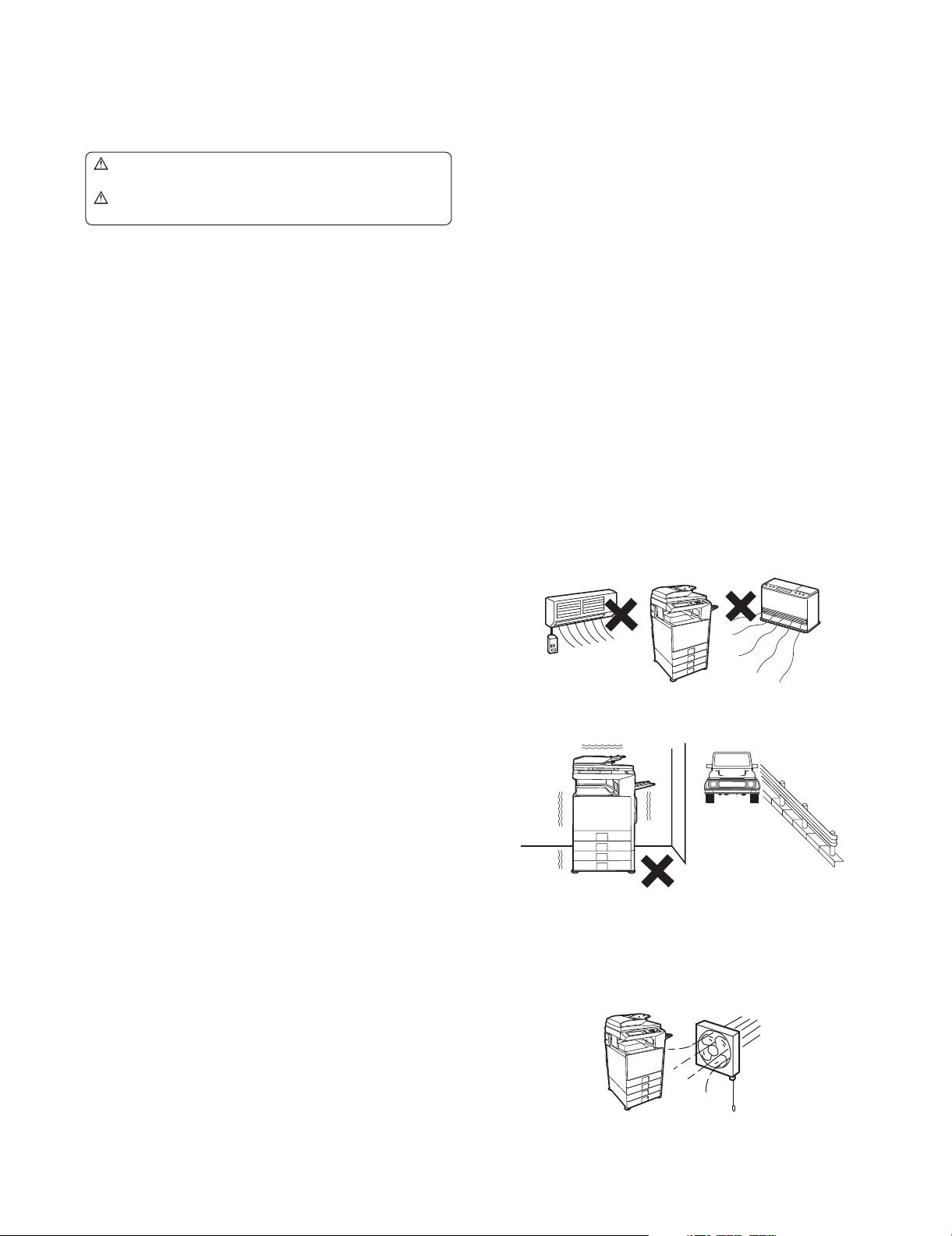
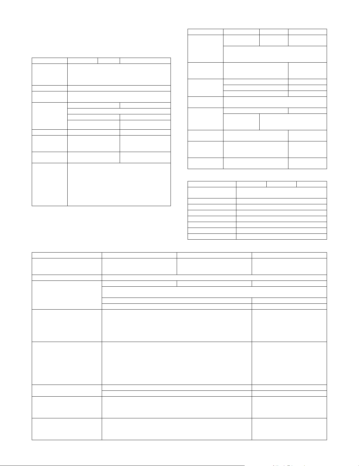
3. Note for installing site
Do not install the machine at the following sites.
1) Place of high temperature, high humidity, low tempera-
ture, low humidity, place under an extreme change in temperature and humidity.
Paper may get damp and form dews inside the machine, causing paper jam or copy dirt.
For operating and storing conditions, refer to the specifications
described later.
2) Place of much vibrations
It may cause a breakdown.
2. Warning for servicing
1) Be sure to connect the power cord only to a power outlet that
meets the specified voltage and current requirements.
Avoid complex wiring, which may lead to a fire or an electric
shock.
It may cause a fire or an electric shock.
2) If there is any abnormality such as a smoke or an abnormal
smell, interrupt the job and disconnect the power plug.
It may cause a fire or an electric shock.
3) Be sure to connect the grounding wire. If an electric leakage
occurs without grounding, a fire or an electric shock may
result.
To protect the machine and the power unit from lightening,
grounding must be made.
4) When connecting the grounding wire, never connect it to the
following points.
It may cause an explosion, a fire or an electric shock.
MX3500N NOTE FOR SERVICING - i
3) Poorly ventilated place
An electro-static type copier will produce ozone inside it.
The quantity of ozone produced is designed to a low level so
as not to affect human bodies. However, continuous use of
such a machine may produce a smell of ozone. Install the
machine in a well ventilated place, and ventilate occasionally.
Page 4
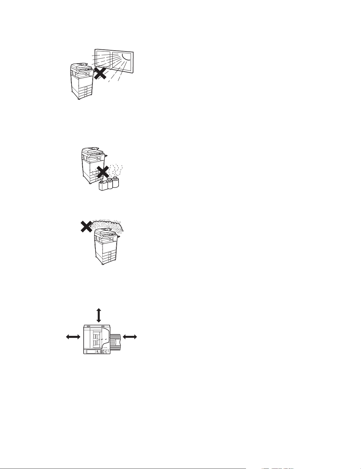
4) Place of direct sunlight.
Plastic parts and ink may be deformed, discolored, or may
undergo qualitative change.
It may cause a breakdown or copy dirt.
5) Place which is full of organic gases such as ammonium
The organic photoconductor (OPC) drum used in the machine
may undergo qualitative change due to organic gases such as
ammonium.
Installation of this machine near a diazo-type copier may result
in dirt copy.
6) Place of much dust
When dusts enter the machine, it may cause a breakdown or
copy dirt.
7) Place near a wall
Some machine require intake and exhaust of air.
If intake and exhaust of air are not properly performed, copy
dirt or a breakdown may be resulted.
30 cm
30 cm
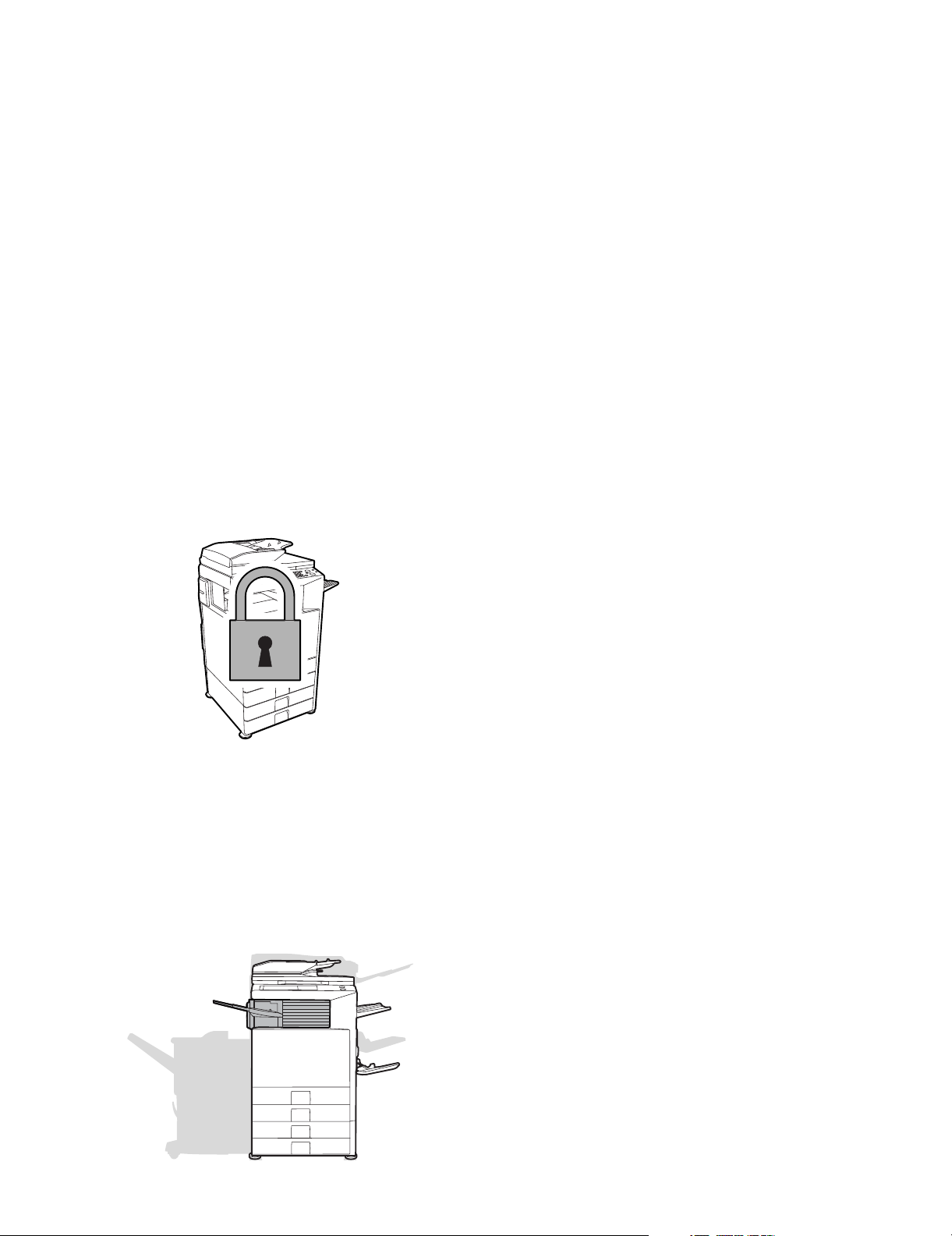
8) Unstable or slant surface
If the machine drops or fall down, it may cause an injury or a
breakdown.
If there are optional paper desk and the copier desk specified,
it is recommendable to use them.
When using the optional desk, be sure to fix the adjuster and
lock the casters.
45 cm
MX3500N NOTE FOR SERVICING - ii
Page 5
MX3500N
[1] PRODUCT OUTLINE
1. Product features
A. Features
(1) Features
1) The employment of newly developed toner reduces the toner
consumption remarkably, realizing high fidelity pictures of
human skin, half tone, and hair. In addition, the employment of
"Auto Color" function, Sharp's unique auto recognition function, reproduces documents of difficult reproduction.
2) The power consumption for FAX standby with the power OFF
is 1W or less, reducing energy expenses of nighttime and load
to the environment.
3) Extension of the lifetime of the OPC drums together with the
frequency of maintenance realizes resource saving.
4) The unique security system inhibits unauthorized use of the
machine, preventing against leak of information.
• The electronic data are encrypted and saved in the hard
disk. When copying or printing or when sending FAX or
scanning, data are automatically erased to protect against
leak of important information (When option installed.).
• The user authentication system by a login name, a pass-
word, and an e-mail address is employed to prevent against
unauthorized use of a third party and to limit the use quantity
and usable functions for each user group. In addition, the
user authentication by the optional IC card read/writer may
be used.
(2) Environmental features
5GTXKEG/CPWCN
• Energy saving design by pre-heat mode/auto power shut-off
mode.
• Conforms to the International EnergyStar program.
• Conforms to the standards of Law on Promoting Green Purchasing.
• Conforms to the Europe RoHS regulations.
(The contents of lead, mercury, hexavalent chromium, cadmium,
PBB [polybrominated biphenyl], PBDE [polybrominated diphenyl
ether] are limited to the regulated level or less.)
5) The open systems architecture (Sharp OSA) is supported
which provides application development environment according to user's needs.
6) Compact area for installation even to a space for a monochrome machine
The machine can be installed to a space for a monochrome
machine, the smallest space in the class of 645mm (W) x
670mm (D), helping backup of color documentations in an
office. The installation of the optional finisher (MX-FNX1)
which is stored in the center paper exit section of the machine
allows stapling and finishing such as punch holes automatically, improving the work efficiency.
MX3500N PRODUCT OUTLINE 1 – 1
Page 6
: May 15 2006
4
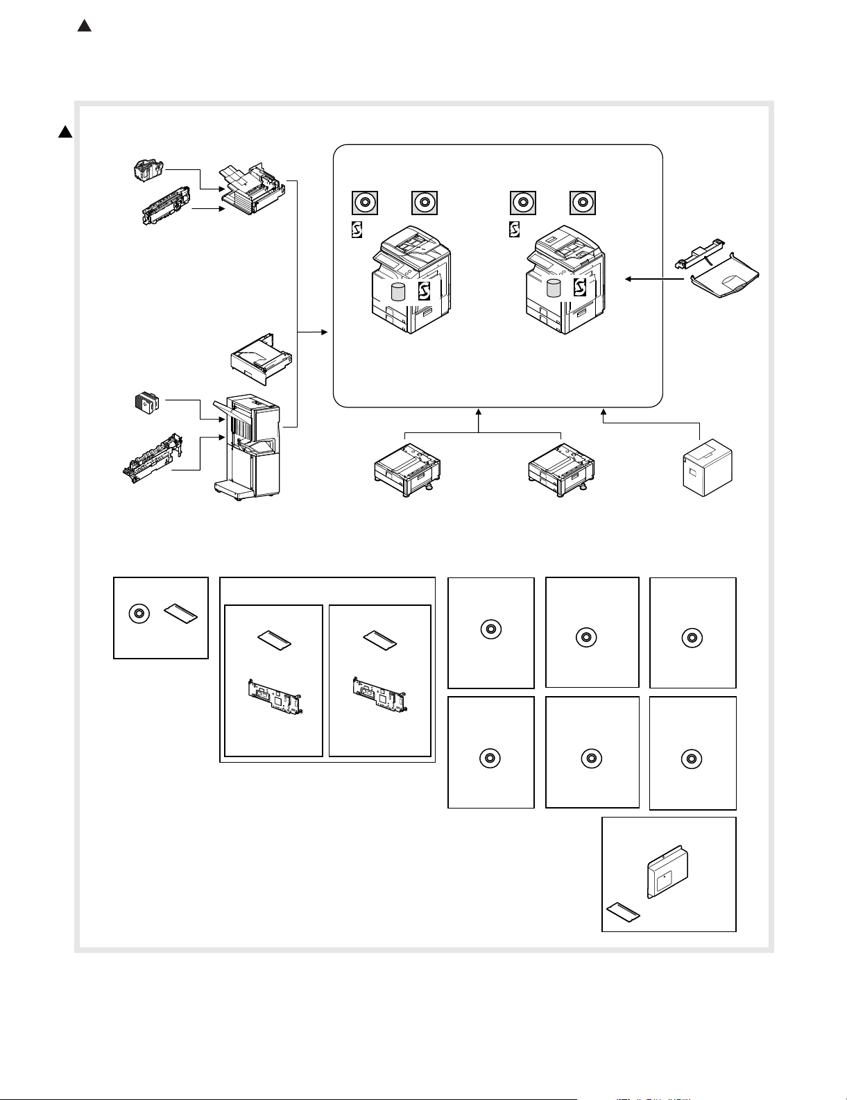
2. Configuration
A. Lineup (Main unit and option)
4
9. Punch module
●
●
●
●
10. Staple cartridge
(Approx. 5000 x 3)
(MX-SCX1)
8. Punch module
●
2-hole (MX-PNX1A)
●
3-hole (MX-PNX1B)
●
4-hole (MX-PNX1C)
●
4-hole (broad space)
(MX-PNX1D)
11. Staple cartridge
(Approx. 5000 x 3)
(AR-SC2)
2-hole (AR-PN1A)
3-hole (AR-PN1B)
4-hole (AR-PN1C)
4-hole (broad space)
(AR-PN1D)
7. Finisher
(MX-FNX1)
5. Paper pass unit
(MX-RBX1)
6. Saddle stitch finisher
(MX-FNX2)
PCL5c/PCL6
driver
RSPF
Network
scanner
(Sharpdesk 1 license)
*&&
Copier/Printer
/Scanner model
(MX-3500N)
(MX-4500N)
1. Stand/1x500 sheet
paper drawer
(MX-DEX3)
PCL5c/PCL6
driver
DSPF
Network
scanner
(Sharpdesk 1 license)
HDD
Copier/Printer
/Scanner model
(MX-3501N)
(MX-4501N)
2. Stand/2x500 sheet
paper drawer
(MX-DEX4)
4. Exit tray unit
(MX-TRX2)
3. Large capacity tray
(MX-LCX1)
12. Barcode font kit
CD
ROM
(AR-PF1)
(Including document control)
13. Commercial
version
Security
ROM
For document
control PWB
(MX-FRX2U)
Data security kit
14.
CC authentication
version
For document
control PWB
(MX-FRX2)
Security
ROM
15. PS3
expansion
kit
CD
(MX-PKX1)
19. Sharpdesk
10 license kit
20. Sharpdesk
50 license kit
CD
(MX-US10/
US50)
16. Internet Fax
expansion kit
CD
(MX-FWX1)
21. Sharpdesk
100 license kit
CD
(MX-USA0)
23. Facsimile expansion kit
17. Sharpdesk
1 license kit
18. Sharpdesk
5 license kit
CD
(MX-USX1/
USX5)
22. Application
integration
module
CD
(MX-AMX1)
(MX-FXX1)
FAX memory (8MB)
(packed together)
MX3500N PRODUCT OUTLINE 1 – 2
Page 7
: May 15 2006
4
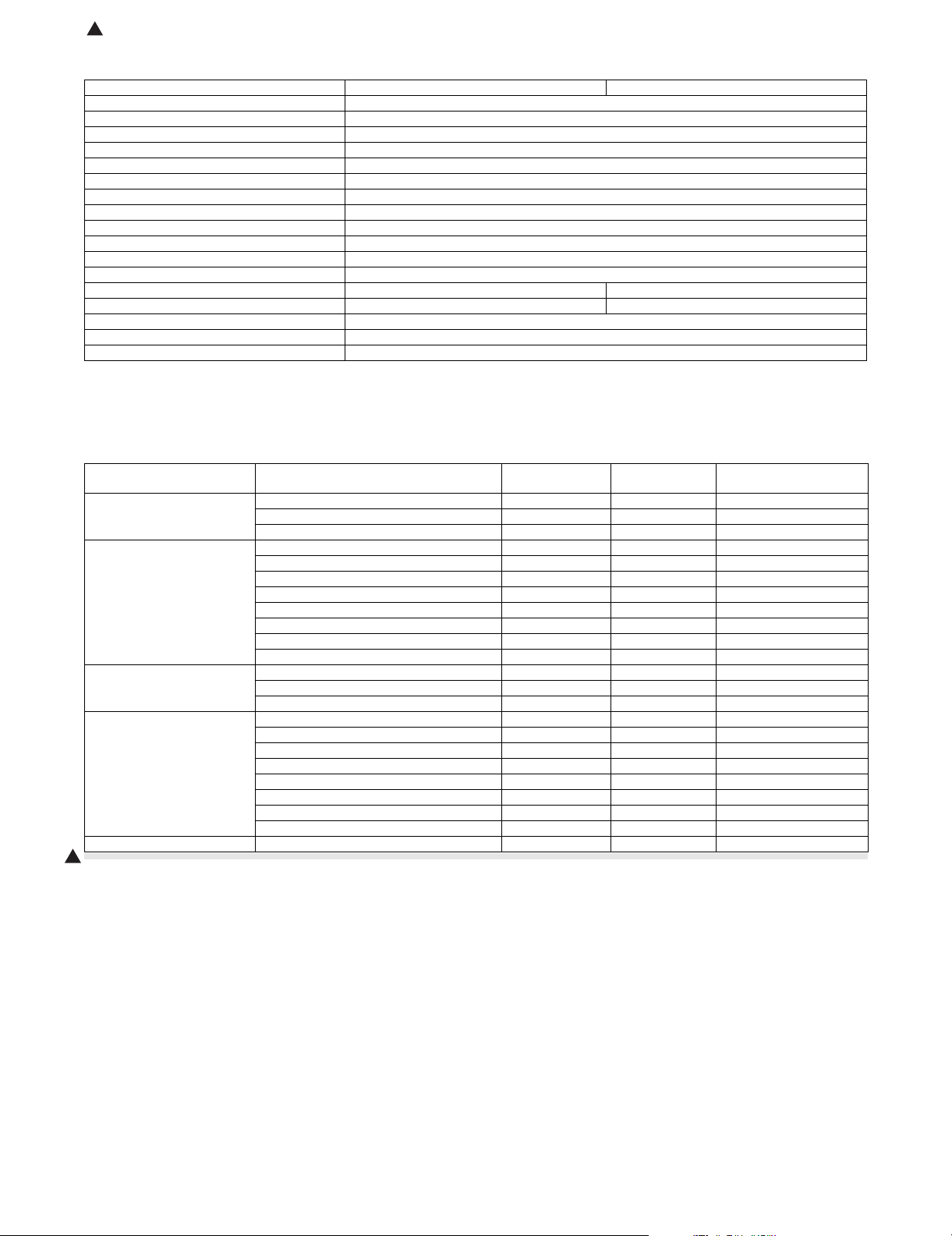
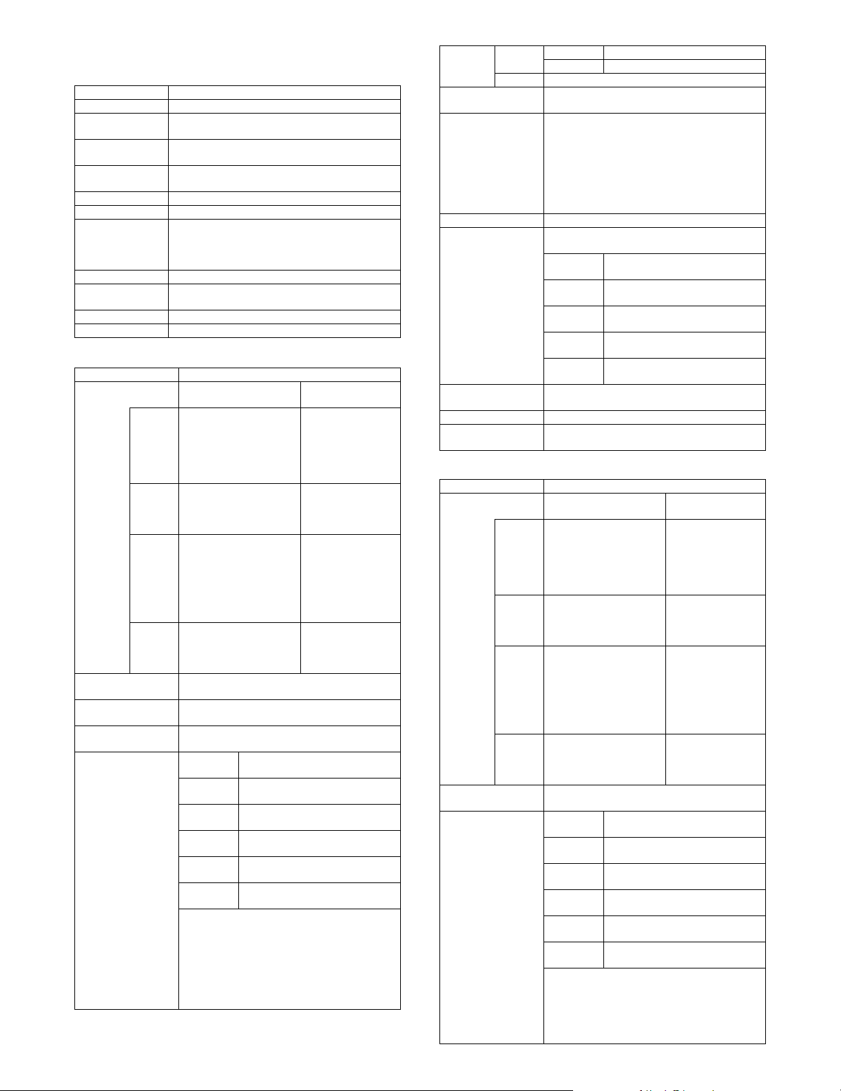
B. Machine configuration
MX-3500N/MX-4500N MX-3501N/MX-4501N
Copier memory (Local memory) (MB) 768
Printer memory (System memory) (MB) 640
Copier STD
GDI printer STD
PCL printer STD
PS printer OP*1
EFI printer OP
Main body LCD MONOCHROME HVGA 8.9"
FAX OP*2
Scanner STD
Filing STD
HDD STD
RSPF STD –
DSPF –STD
Automatic duplex STD
Security OP*1
Internet Fax OP*1
STD: Standard provision, OP: Option
OP*1: Product key target.
OP*2: No support for some areas.
C. Combination of options list
Section Name Model name
Paper feed system 1. Stand/1x500 sheet paper drawer MX-DEX3 OPT
2. Stand/2x500 sheet paper drawer MX-DEX4 OPT
3. Large capacity tray MX-LCX1 OPT (A4)
Paper exit system 4. Exit tray unit MX-TRX2 OPT
5. Paper pass unit MX-RBX1 OPT
6. Saddle stitch finisher MX-FNX2 OPT
7. Finisher MX-FNX1 OPT (Inner finisher)
8. Punch module (For inner finisher) MX-PNX1 A/B/C/D OPT
9. Punch module (For saddle stitch finisher) AR-PN1 A/B/C/D OPT (Common in current models)
10. Staple cartridge (For inner finisher) MX-SCX1 OPT (Approx. 5000 x 3)
11. Staple cartridge (For saddle stitch finisher) AR-SC2 OPT (Approx. 5000 x 3)
Electrical system (ROM) 12. Barcode font kit AR-PF1 OPT (Conventional model)
13. Data security kit MX-FRX2U OPT (Commercial version)
14. Data security kit MX-FRX2 OPT (Authentication version)
Electrical system (Software) 15. PS3 expansion kit MX-PKX1 OPT
16. Internet Fax expansion kit MX-FWX1 OPT (Internet Fax)
17. Sharpdesk 1 license kit MX-USX1 OPT
18. Sharpdesk 5 license kit MX-USX5 OPT
19. Sharpdesk 10 license kit MX-US10 OPT
20. Sharpdesk 50 license kit MX-US50 OPT
21. Sharpdesk 100 license kit MX-USA0 OPT
22. Application integration module MX-AMX1 OPT
Electrical system (FAX) 23. Facsimile expansion kit MX-FXX1 OPT*1
4
MX-3500N/3501N
MX-4500N/4501N
Remarks
STD: Standard provision. OPT: Installable option.
*1: No support for some areas.
MX3500N PRODUCT OUTLINE 1 – 3
Page 8
MX3500N
[2] SPECIFICATIONS
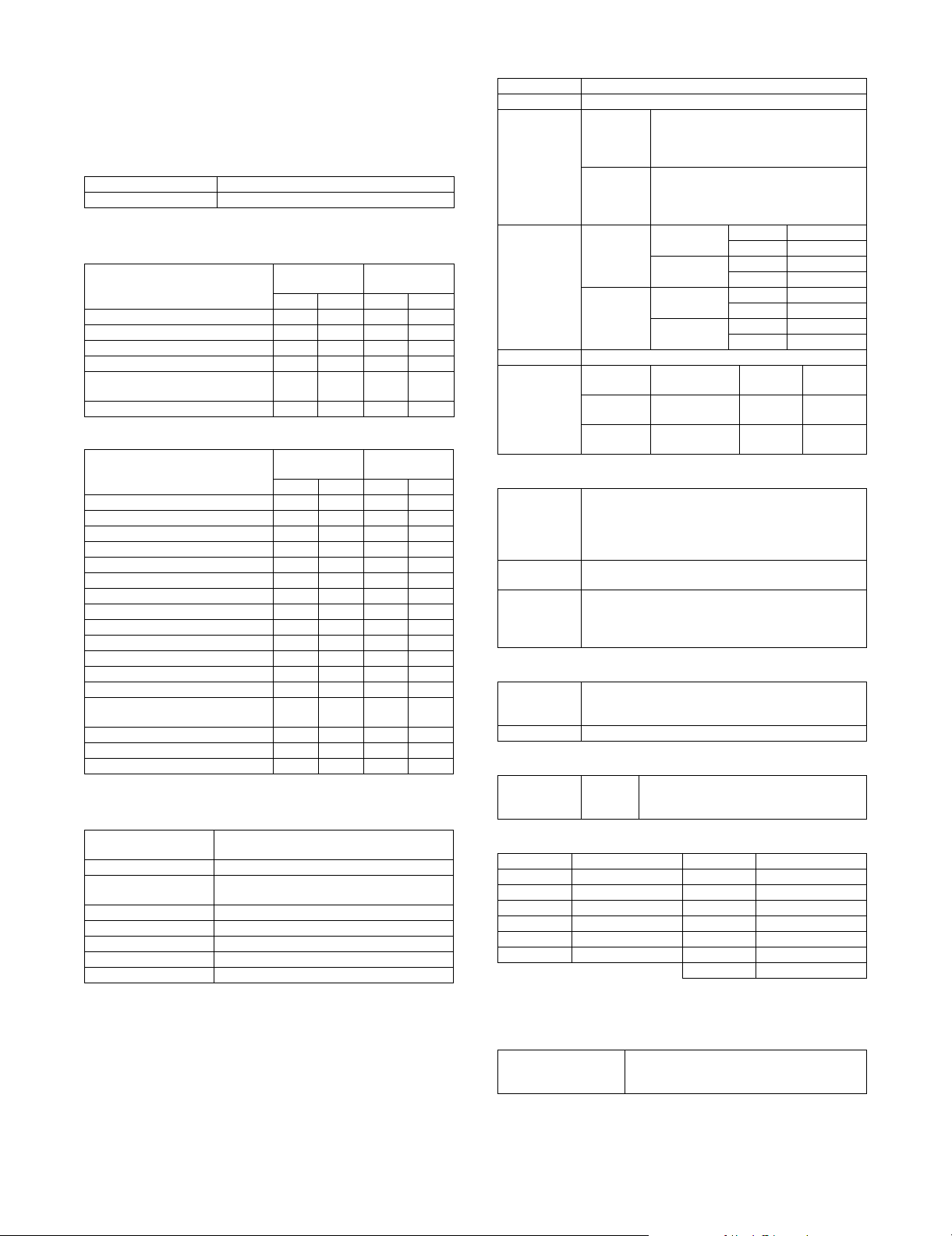
1. Basic specifications
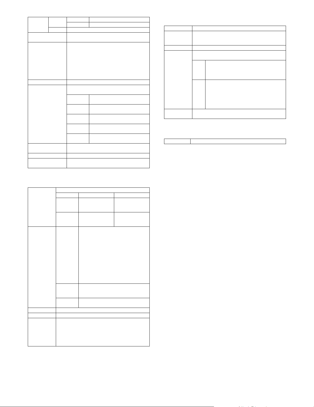
A. Base engine
(1) Type
Type Desk-top
Color support Full color
(2) Engine speed
a. Tray1 – 4 (Main unit), LCC
MX-4500N
Paper size
A3, 11 x 17, 8K 20 17 17 17
B4, 8.5 x 14, 8.5 x 13 22 20 20 20
A5R, 5.5 x 8.5R 32 25 25 25
A4, B5, 8.5 x 11, 16K 45 35 35 35
A4R, B5R, A5R, 8.5 x 11R,
7.25 x 10.5R, 5.5 x 8.5R, 16KR
Extra 19161616
MX-4501N
B/W Color B/W Color
30 25 25 25
b. Manual (Main unit)
MX-4500N
Paper size
A3, 11 x 17, 8K 19 15 16 15
B4, 8.5 x 14, 8.5 x 13 20 16 17 16
A4, 8.5 x 11, 16K 22 18 18 18
B5 41 29 31 29
A4R, 16KR 41 31 31 31
8.5 x 11R 30 20 25 20
B5R, 7.25 x 10.5R 30 21 25 21
A5R, 5.5 x 8.5R 30 22 25 22
12 x 18 32 25 25 25
OHP(A4, 8.5 x 11) 15 14 15 14
OHP(A4R, 8.5 x 11R) 12 10 12 10
Extra 19151615
Envelope 16 15 16 15
Heavy paper (B5, A4, A5R, 8.5 x 11,
8.5 x 5.5R, 16K)
Heavy paper (Postcard HIGH)*1 15 14 15 14
Heavy paper (Postcard LOW)*1 8888
Heavy paper (Other sizes) 8888
MX-4501N
B/W Color B/W Color
15 14 15 14
*1: Switched by the service simulation setting
(3) Engine composition
Photoconductor kind OPC (Drum diameter: Black; I30mm, Color;
Copying method Electronic photo (Laser)
Developing system Dry-type dual-component magnetic brush
Charging system Charged saw-tooth method
Transfer system Intermediate transfer belt
Cleaning system Counter blade
Fusing system Heat roller
Waste toner disposal No toner recycling system
I30mm x 3)
development
MX-3500N
MX-3501N
MX-3500N
MX-3501N
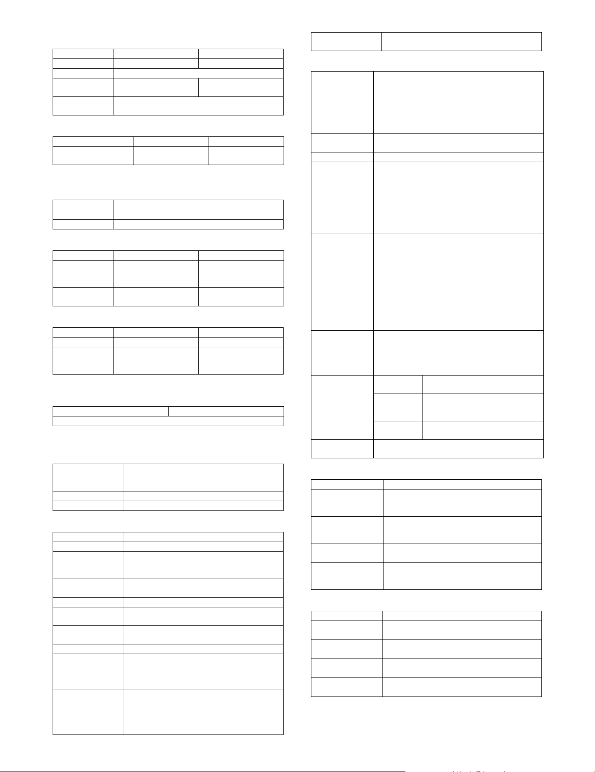
(4) Shifter
5GTXKEG/CPWCN
Typ e Sh ifte r
Paper weight 55 – 209g/m
Paper size Non offset
Productivity
(A4, 8.5x11)
Offset range 30mm
Range of error
(In using the
recommended
paper, A4/8.5
x 11)
mode
(Normal
output)
Offset
mode
Non-offset
(Normal
output)
Offset
mode
Non-offset Not drop from
Offset
mode
2
(17 – 56 lbs)
A3, B4, A4R, B5, B5R, A5R, Postcard, 8K,
16K, 16KR,11 x 17, 8.5 x 14, 8.5 x 13,
8.5 x 11, 8.5 x 11R, 7.25 x 10.5R,
5.5 x 8.5R, Envelope, Extra
A3, B4, A4R, B5, B5R, A5R, Postcard, 8K,
16K, 16KR, 11 x 17, 8.5 x 14, 8.5 x 13,
8.5 x 11, 8.5 x 11R, 7.25 x 10.5R, 5.5 x
8.5R (Not Envelope, Extra)
MX-3500N B/W 35cpm
MX-4500N B/W 45cpm
MX-3500N B/W 35cpm
MX-4500N B/W 45cpm
Horizontal
direction
the tray.
Within 50mm Within
Color 35cpm
Color 35cpm
Color 35cpm
Color 35cpm
Verti cal
direction
--
r10mm
Between
Jobs
Min.10mm
(5) Engine resolution
Resolution Writing:
Smoothing
function
Gradation Writing:
600 x 600dpi
1200 x 600dpi (Monochome printing only.)
* Rotation output not allowed at 1200dpi x 600dpi. PS
expansion kit needed.
None
Monochrome: 2 levels (1bit) * 256 levels equivalent
Color: Each color 2 levels (1bit) / Each color 16 levels
(4bits) * 256 levels equivalent
(6) Warmup
Warmup time 240 sec or less
Pre-heat Yes
* The value may be increased if process-control
processing is being executed.
(7) Jam recovery time
With the door
open
Approx.
60 sec
Condition: After the door is kept open for 60
seconds, standard setting, the polygon
motor halt
(8) Printable area
A3 293 x 413mm 12 x 18 * 279 x 432mm
B4 253 x 357mm 11 x 17 275 x 425mm
A4 206 x 290mm 8.5 x 14 212 x 349mm
B5 178 x 250mm 8.5 x 13 212 x 323mm
A5 144 x 203mm 8.5 x 11 212 x 272mm
7.25 x 10.5 180 x 260mm 5.5 x 8.5 136 x 209mm
Postcard 96 x 141mm 8K 266 x 383mm
16K 191 x 263mm
* The printable area for 12 x 18 must be as large as the A3/11 x 17
page dimension by PCL / PS driver.
(9) Void area
Void area
Image loss
MX3500N SPECIFICATIONS 2 – 1
Top: 4 mm or less
Bottom: 3 mm or less
FR Total: 4 mm or less
Page 9
(10) Power source
Voltage / Current 100 – 127V 12A 220 – 240V 8A
Frequency 50/60Hz
Power source
code
Power switch 2 switches (Primary switch: in the front cover;
100V type 200V type
Fixed type (direct) Inlet type
Seconday switch: the operation panel)
(11) Power consumption
Maximum rated power
consumption
*1: Heater is OFF when power source ON.
100V type 200V type
1.44kW 1.84kW
(12) Noise
In action B/W : 63dB or less
Standby B/W : 55dB or less
Color : 63dB or less
(13) Dimensions
Outer dimensions
(W x D x H)
Footprint (W x D) 645 x 670mm
MX-3500N/MX-4500N MX-3501N/MX-4501N
645 x 670 x 950mm
(25 25/64 x 26 3/8 x
37 26/64 inch)
(25 25/64 x 26 3/8 inch)
645 x 670 x 960mm
25 25/64 x 26 3/8 x
37 51/64 inch)
645 x 670mm
(25 25/64 x 26 3/8 inch)
(14) Weight
Main unit Approx. 114kg (251lbs) Approx.123kg (271lbs)
Main unit +
Developer +
Toner cartridge
MX-3500N/MX-4500N MX-3501N/MX-4501N
Approx. 119kg (262lbs) Approx.128kg (282lbs)
(15) Dimensions occupied by Machine (with Multi
Manual/Exit tray extended)
MX-3500N/MX-4500N MX-3501N/MX-4501N
W1075 x D 670mm (W42 21/64 x D26 3/8 inch)
B. Paper feed unit/Transport/Paper exit secton
(1) Machine paper feed tray
Form Standard: Double feeder tray + multi manual
Feeding method Feeding from the upper section with front loading
Heater (Engine part) Service parts
(2) Paper feed tray 1/tray 2
Feeding method Feeding from the upper section with front loading
Heater (Engine part) Service parts
Paper size A3, B4, A4, A4R, B5, B5R, A5R, 8K, 16K, 16KR
Changing of paper
size
Paper type setting Yes
Default paper size
setting
Feedable paper
type/weight
Paper capacity Standard paper: 500 sheets (80g/m
Paper Type Plain paper, pre-printed paper (not including
Paper size detection
* About A5R, 5.5 x
8.5R, 8K, 16K,
16KR, manual
setting.
Maximum: Fourfold feeder tray + multi manual +
large capacity feeder cassette
11 x 17, 8.5 x 14, 8.5 x 13, 8.5 x 11,
8.5 x 11R, 7.25 x 10.5R, 5.5 x 8.5R
Guide adjustment by users
Shipped with max. width of paper guide
Plain paper: 60-105g/m
backing paper), recycled paper, letter head, prepunched paper, colored paper
* Users can set up all of these paper types.
A3, B4, A4, A4R, B5, B5R, A5R, 8.5 x 13
11 x 17, 8.5 x 14, 8.5 x 11, 8.5 x 11R, 7.25 x 10.5R
2
(16-28 lbs)
2
, 21lbs)
Detection of
Remaining Paper
Level detection (4 levels: 100%, 67%, 33%, and
none)
(3) Manual feed tray (Bypass tray)
Paper Size A3, B4, A4, A4R, B5, B5R, A5R, 8K, 16K, 16KR
Changing of
paper size
Paper type setting Yes
Feedable paper
type/weight
Paper capacity Standard paper: 100 sheets
Paper Type Plain paper, pre-printed paper (Excluding back print
Paper size
detection
Detection of
remaining paper
12 x 18, 11 x 17, 8.5 x 14, 8.5 x 13, 8.5 x 11, 8.5 x
11R, 7.25 x 10.5R, 5.5 x 8.5R
Envelope (Monarch / Com-10 / DL / C5 / Rectangle 3 /
Western 2 / Western 4)
Extra Size (Tab paper is limited to A4; tab width
12mm-20mm / 8.5 x 11; tab width 6.1-17mm)
Guide adjustment by users
Thin paper: 55 – 59g/m
Plain paper: 60 – 105g/m
Heavy Paper: 106 – 209g/m
Envelope: 75 – 90g/m
OHP
Label paper
Tab paper
Gloss Paper
Envelope: 20 sheets
OHP: 20 sheets
Heavy paper: 40 sheets
Tab paper: 20 sheets
Gloss paper: 20 sheets *
Other special paper: 1 sheet
* The gloss paper is sucked under a high
temperature environment to cause double feed or
misfeed. In such a case, manually supply paper
sheet by sheet (Select heavy paper).
paper), recycled paper, letter head, pre-punched
paper, colored paper, heavy paper, thin paper, label
paper, OHP, tab paper, envelope.
* Users can set up all of these paper types.
Auto Detect
Auto-AB
Auto Detect
Auto-Inch
For China A3, B4, A4, A4R, B5, B5R, A5R, 11 x
yes or no only
2
(15 – 16 lbs)
2
(16 – 28 lbs)
2
(28 – 56 lbs)
2
(20 – 24 lbs)
A3, B4, A4, A4R, B5, B5R, A5R, 8.5 x
13, Postcard, 8.5 x 11, 11 x 17
12 x 18, 11 x 17, 8.5 x 14, 8.5 x 11,
8.5 x 11R, 5.5 x 8.5R, 7.25 x 10.5R,
A3, B4, A4, B5
17, 8.5 x 14, 8.5 x 11, 8K, 16K
(4) Double-sided
Method Non-Stack
Paper size A3, B4, A4, A4R, B5, B5R, A5R, 8K, 16K, 16KR,
Paper type Plain paper, pre-printed paper (not including
Paper weight
(for duplex operation)
Logo paper support For paper such as letterhead paper with front-
11 x 17, 8.5 x 14, 8.5 x 13, 8.5 x 11, 8.5 x 11R,
8.5 x 5.5R
backing paper), recycled paper, letter head, prepunched paper, colored paper
Plain paper: 60-105g/m
Heavy paper: 106-209g/m
back attributes, the engine control must be cared
for printing side.
2
(16-28 lbs)
2
(28-56 lbs)
(5) Paper exit tray (Center tray)
Exit location/method Face down in the main unit
Exit capacity 500 sheets (A4 or 8.5 x 11 (color recommended
Exit paper size/type All feedable paper except 12x18.
Exit paper detection No
Exit tray full
detection
Shifting function Yes
Rotation sort No
paper))
Yes
MX3500N SPECIFICATIONS 2 – 2
Page 10
(6) Paper exit tray unit (Right tray)
* Option (MX-TRX2)
Form Exit tray unit
Transport standard Center standard
Ejecting location/
method
Tray capacity 100 sheets (A4 or 8.5 x 11 (color recommended
Ejected paper size/
type
Full tray detection Yes
Shifter No
Dimensions W314 x D405 x H52mm
Weight Approx. 0.93kg (2 lbs)
Installation/
maintenance
Optional detection Setting by simulation (Sim. 26-1)
Packaged items Exit tray, full actuator
External ejection from the right face of the main unit
/ face-down ejection
paper))
Any feedable paper except envelope and tab paper.
(W12 23/64 x D15 61/64 x H2 3/64 inch)
With tray extended: W444 x D405 x H52mm (W17
31/64 x D15 61/64 x H2 3/64 inch)
Installation by service personnel.
(7) Reversing single pass feeder
Form RSPF (Reversing single pass feeder)
Scan speed Monochrome
Copy 1-sided: 45 sheets/minute
Fax 1-sided: 48 sheets/minute
Scanner 1-sided: 48 sheets/minute
Internet
Fax
Document setup
direction
Document standard
location
Document transport
method
Document sizes Inch type-1 11 x 17, 8.5 x 14, 8.5 x 11,
(A4/8.5 x 11)
(600 x 300dpi, 1bit)
2-sided: 15 pages/minute
(600 x 300dpi, 1bit)
(200 x 200dpi, 1bit)
2-sided: 15 pages/minute
(200 x 200dpi, 1bit)
(200 x 200dpi, 1bit)
2-sided: 15 pages/minute
(200 x 200dpi, 1bit)
1-sided: 48 sheets/minute
(200 x 200 dpi, 1bit)
2-sided: 15 pages/minute
(200 x 200 dpi, 1bit)
Upward standard (1toN feeding standard)
Center standard (Rear one-side standard for
random feeding)
Sheet-through method
8.5 x 11R, 8.5 x 5.5, A4, A3
Inch type-2 11 x 17, 8.5 x 13, 8.5 x 11,
8.5 x 11R, 8.5 x 5.5, A4, A3
AB type-1 A3, B4, A4, A4R, B5, B5R, A5,
8.5 x 11, 8.5 x 14, 11 x 17
AB type-2 A3, B4, A4, A4R, B5, B5R, A5,
8.5 x 11, 216 x 330, 11 x 17
AB type-3 A3, B4, A4, A4R, A5, 8K, 16K,
16KR, 8.5 x 11, 216 x 330, 11 x 17
Long paper 800mm (Monochrome 2 levels
only)
Mixed feeding (same type / same width) possible
Random feeding (feeding of different types /
different widths)
Only the following combinations of 2 size types
are allowed: A3 and B4; B4 and A4R; A4 and B5;
B5 and A5; and 11-inch and 8.5-inch.
2-sided scanning is disabled during random
feeding.
Color
(A4/8.5 x 11)
1-sided: 35 sheets/
minute (600 x
600dpi, 4bit)
2-sided: 13 pages/
minute (600 x
600dpi, 4bit)
N/A
1-sided: 35 sheets/
minute (200 x
200dpi, 8bit) (when
in full color)
2-sided: 15 pages/
minute (200 x
200dpi, 8bit)
N/A
Document
weights
Document carrying
capacity
Types of document
that may not be
transported
Paper detection Yes
Paper detection size Auto detection (Switching one type of detection
Paper feeding
direction
Document inversion Yes
Simultaneous double-
sided scanning
1-side Thin paper 35 – 49g/m2 (9 – 13 lbs)
Plain paper 50 – 128g/m
2-side 50 – 128 g/m
Maximum: 100 sheets (80g/m
Maximum: 13 mm, 1/2 inch or less
The following documents are NOT allowed:
OHP, second original drawing, tracing paper,
carbon paper, thermal paper, wrinkled / broken /
torn document, document with cuts and pastes,
documents printed by an ink ribbon, and
perforated document except 2-punched / 3punched (Perforated document by punch unit is
allowed.)
unit through system setting)
Inch-1 11 x 17, 8.5 x 14, 8.5 x 11,
Inch-2 11 x 17, 8.5 x 13, 8.5 x 11,
AB-1 A3, B4, A4, A4R, B5, B5R, A5, 8.5
AB-2 A3, B4, A4, A4R, B5, B5R, A5, 8.5
AB-3 A3, B4, A4, A4R, A5, 8K, 16K,
Right hand feeding
Not allowed
2
(13 – 34 lbs)
8.5 x 11R, 5.5 x 8.5, A4, A3
8.5 x 11R, 5.5 x 8.5, A4, A3
x 11, 8.5 x 14, 11 x 17
x 11, 216 x 330, 11 x 17
16KR, 8.5 x 11, 216 x 330, 11 x 17
2
(13 – 34 lbs)
2
, 21lbs), or
(8) Duplex single pass feeder
Form DSPF (Duplex single pass feeder)
Scan speed Monochrome
Copy 1-sided: 45 sheets/minute
Fax 1-sided: 60 sheets/minute
Scanner 1-sided: 60 sheets/minute
Internet
Fax
Document standard
location
Document sizes Inch type-1 11 x 17, 8.5 x 14, 8.5 x 11,
(A4/8.5 x 11)
(600 x 300dpi, 1bit)
2-sided: 45 pages/minute
(600 x 300dpi, 1bit)
(200 x 200dpi, 1bit)
2-sided: 60 pages/minute
(200 x 200dpi, 1bit)
(200 x 200dpi, 1bit)
2-sided: 60 pages/minute
(200 x 200dpi, 1bit)
1-sided: 60 sheets/minute
(200 x 200 dpi, 1bit)
2-sided: 15 pages/minute
(200 x 200 dpi, 1bit)
Center standard (Rear one-side standard for
random feeding)
8.5 x 11R, 8.5 x 5.5, A4, A3
Inch type-2 11 x 17, 8.5 x 13, 8.5 x 11,
8.5 x 11R, 8.5 x 5.5, A4, A3
AB type-1 A3, B4, A4, A4R, B5, B5R, A5,
8.5 x 11, 8.5 x 14, 11 x 17
AB type-2 A3, B4, A4, A4R, B5, B5R, A5,
8.5 x 11, 216 x 330, 11 x 17
AB type-3 8K, A4, A4R, B4, 16K, 16KR,
A5, 8.5 x 11, 216 x 330, 11 x 17
Long paper 800mm (Monochrome 2 levels
only)
Mixed feeding (same type / same width) possible
Random feeding (feeding of different types /
different widths)
Only the following combinations of 2 size types
are allowed: A3 and B4; B4 and A4R; A4 and B5;
B5 and A5; and 11-inch and 8.5-inch.
Color
(A4/8.5 x 11)
1-sided: 35 sheets/
minute (600 x
600dpi, 4bit)
2-sided: 35 pages/
minute (600 x
600dpi, 4bit)
N/A
1-sided: 35 sheets/
minute (200 x
200dpi, 8bit) (when
in full color)
2-sided: 35 pages/
minute (200 x
200dpi, 8bit)
N/A
MX3500N SPECIFICATIONS 2 – 3
Page 11
Document
weights
Document carrying
capacity
Types of document
that may not be
transported
Paper detection Yes
Paper detection size Auto detection (Switching one type of detection
Paper feeding
direction
Document inversion Yes
Simultaneous double-
sided scanning
1-side Thin paper 35 – 49g/m2 (9 – 13 lbs)
Plain paper 50 – 128g/m
2-side 50 – 128 g/m
Maximum: 150 sheets (80g/m
Maximum: 19.5 mm, 3/4 inch or less
The following documents are NOT allowed:
OHP, second original drawing, tracing paper,
carbon paper, thermal paper, wrinkled / broken /
torn document, document with cuts and pastes,
documents printed by an ink ribbon, and
perforated document except 2-punched / 3punched (Perforated document by punch unit is
allowed.)
unit through system setting)
Inch-1 11 x 17, 8.5 x 14, 8.5 x 11,
Inch-2 11 x 17, 8.5 x 13, 8.5 x 11,
AB-1 A3, B4, A4, A4R, B5, B5R, A5, 8.5
AB-2 A3, B4, A4, A4R, B5, B5R, A5, 8.5
AB-3 8K, B4, A4, A4R, 16K, 16KR, A5,
Right hand feeding
Allowed
2
(13 – 34 lbs)
8.5 x 11R, 5.5 x 8.5, A4, A3
8.5 x 11R, 5.5 x 8.5, A4, A3
x 11, 8.5 x 14, 216 x 330, 11 x 17
x 11, 216 x 330, 11 x 17
8.5 x 11, 216 x 330, A3
2
(13 – 34 lbs)
2
, 21lbs), or
C. Scanner section
(1) Resolution/Gradation (or Levels)
(2) Original cover
Scan Range 297 x 432mm
Original Cover
Standard
Location
Detection Yes
Detection Size Auto Detect (One type of detection unit to be switched
Heater
(Scanner part)
Left back as standard
for software destination)
Inch <INCH-1>
11 x 17, 8.5 x 14, 8.5 x 11, 8.5 x 11R, 5.5 x 8.5
<INCH-2>
11 x 17, 8.5 x 13, 8.5 x 11, 8.5 x 11R, 5.5 x 8.5
AB <AB-1>
A3, A4, A4R, A5, B4, B5, B5R
<AB-2>
A3, A4, A4R, A5, B5, B5R, 216 x 330
<AB-3>
8K, A4, A4R, A5, B4, 16K, 16KR
Service parts
D. Fuser section
(1) Type
System Heat roller attachment system
Scan
resolution (dpi)
Original
Cover
RSPF/
DSPF
Transmission
resolution (dpi)
Exposure lamp Xenon
Scan Levels 10bits
Output levels FAX mode: 1bit
Image
process
PC-FAX/
PC-Internet
Fax
Network
TWAIN
Internet Fax mode: 1bit
Scanner mode:
Black & White: 1bit
Gray Scale: 8bit
Full Color: Each color RGB 8bit
Copy mode
Monochrome Color
600 x 600dpi
600 x 300dpi
(Default)
600 x 600dpi
600 x 300dpi
(Default)
(Scanner)
100 x 100dpi / 200 x 200dpi / 300 x 300dpi
/ 400 x 400dpi / 600 x 600dpi
(Internet Fax)
200 x 100dpi (Half tone not allowed) /
200 x 200dpi / 200 x 400dpi /
400 x 400dpi / 600 x 600dpi
(FAX)
Standard (203.2 x 97.8dpi) (Half tone not
allowed) / Fine (203.2 x 195.6 dpi) /
Super fine (203.2 x 391dpi) /
Ultra fine (406.4 x 391 dpi)
200 x 100dpi / 200 x 200dpi / 200 x 400dpi
/ 400 x 400dpi
75dpi / 100dpi / 150dpi / 200dpi / 300dpi /
400dpi / 600dpi or custom: 50-9600dpi
600 x 600dpi
(Default)
600 x 600dpi
(Default)
MX3500N SPECIFICATIONS 2 – 4
Page 12
2. Functional specifications
A. Specifications of copy functions
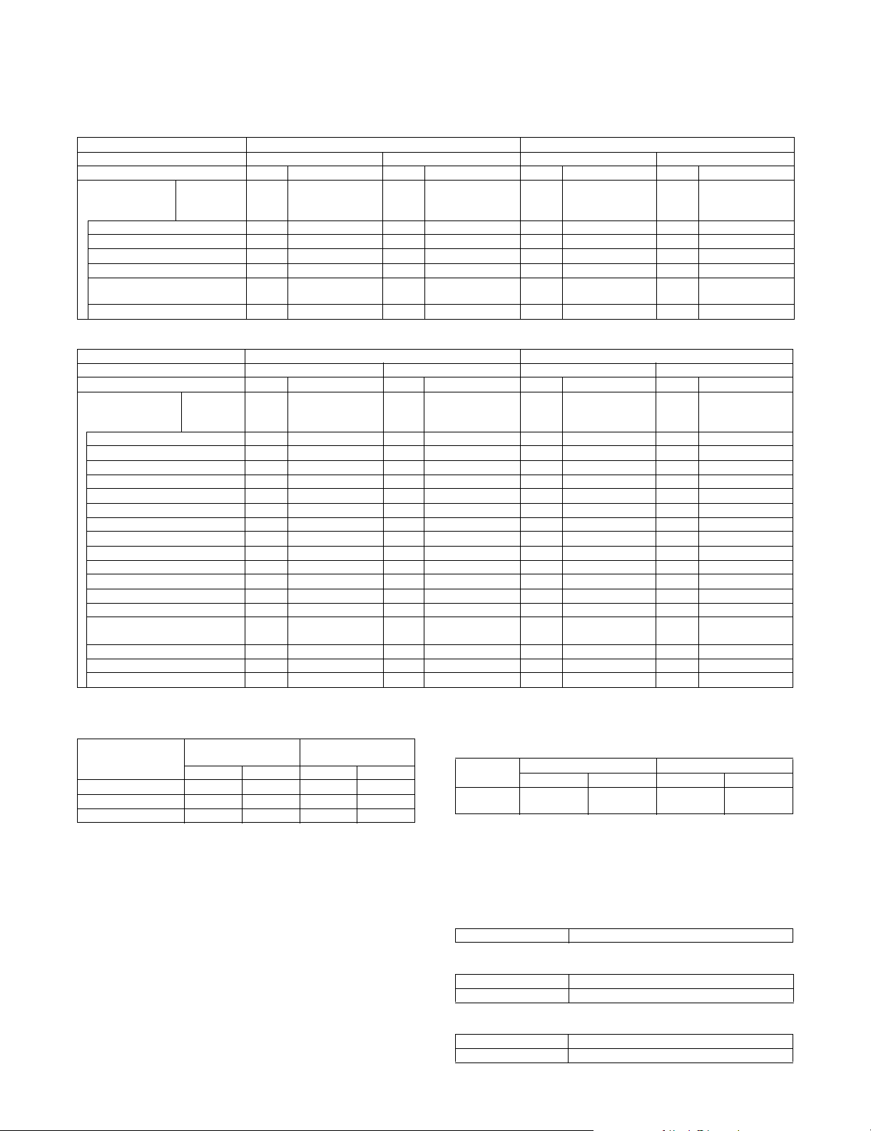
(1) Copy speed (Continuous copy speed)
a. Tray 1 – 4, LCC
Model name MX-4500N/MX-4501N MX-3500N/MX-3501N
Color / B/W Color B/W Color B/W
Print / Copy Print Copy Print Copy Print Copy Pr int Copy
Paper size Magnification Normal Reduction (25%)
A3, 11 x 17, 8K 17 17 20 20 17 17 17 17
B4, 8.5 x 14, 8.5 x 13 20 20 22 22 20 20 20 20
A4, B5, 8.5 x 11, 16K 35 35 45 45 35 35 35 35
A5R, 5.5 x 8.5R 25 25 32 32 25 25 25 25
A4R, B5R, 8.5 x 11R, 16KR,
7.25 x 10.5R
Extra 1616191916161616
25 25 30 30 25 25 25 25
Normal (100%)
Enlargement (400%)
b. Manual feed
Model name MX-4500N/MX-4501N MX-3500N/MX-3501N
Color / B/W Color B/W Color B/W
Print / Copy Print Copy Print Copy Print Copy Print Copy
Paper size Magnification Normal Reduction (25%)
A3W, 12 x 18 15 15 19 19 15 15 16 16
A3, 11 x 17, 8K 16 16 20 20 16 16 17 17
B4, 8.5 x 14, 8.5 x 13 18 18 22 22 18 18 20 20
A4, 8.5 x 11, 16K 29 29 41 41 29 29 31 31
B5 31 31 41 41 31 31 31 31
A5R, 5.5 x 8.5R 25 25 32 32 25 25 25 25
B5R 2222303022222525
8.5 x 11R 21 21 30 30 21 21 25 25
A4R, 7.25 x 10.5R, 16KR 20 20 30 30 20 20 25 25
OHP(A4, 8.5 x 11) 14 14 15 15 14 14 15 15
OHP(A4R, 8.5 x 11R) 10 10 12 12 10 10 12 12
Extra 1515191915151616
Envelope 15 15 16 16 15 15 16 16
Heavy paper (B5, A4, A5R, 8.5 x
11, 8.5 x 5.5R, 16K)
Heavy paper (Postcard HIGH) *1 14 14 15 15 14 14 15 15
Heavy paper (Postcard LOW) *1 8 8 8 8 8 8 8 8
Heavy paper (Other sizes) 8 8 8 8 8 8 8 8
14 14 15 15 14 14 15 15
Normal (100%)
Enlargement (400%)
*1: Switched by the service simulation setting
(2) First copy time
MX-4500N (RSPF),
Platen/RSPF/DSPF
Platen 4.1 sec 6.9 sec 4.7 sec 6.9 sec
RSPF 9.3 sec 14.2 sec 10.1 sec 14.2 sec
DSPF 8.8 sec 15.2 sec 9.5 sec 15.2 sec
MX-4501N (DSPF)
B/W Color B/W Color
[Measuring Conditions]
* Feeding A4/8.5x11paper from the main unit tray 1
* Polygon in rotation
* Auto Color Selection OFF/Auto Color for color OFF
MX-3500N (RSPF),
MX-3501N (DSPF)
Normal Reduction (25%)
Normal (100%)
Enlargement (400%)
Normal Reduction (25%)
Normal (100%)
Enlargement (400%)
(3) Job speed
a. Document changing speed (in copy mode)
S to S 45cpm
* The copy speed in combination of the main unit and the auto
document feed user is defined.
* S to S: A4/8.5 x 11 document, 11 pages and 1 copy (not including
the first copy)
Monochrome: 600 x 300dpi and color: 600 x 600dpi (default)
(4) Continuous copy
Normal Reduction (25%)
Normal Reduction (25%)
(100%)
Normal (100%)
Enlargement (400%)
Normal (100%)
Enlargement (400%)
MX-4500N/MX-4501N MX-3500N/MX-3501N
B/W Color B/W Color
35cpm
(100%)
Normal Reduction (25%)
Normal (100%)
Enlargement (400%)
Normal Reduction (25%)
Normal (100%)
Enlargement (400%)
35cpm
(100%)
35cpm
(100%)
Multi max. number 999 sheets
(5) Resolution
Scan resolution 600 x 600dpi
Writing resolution 600 x 600dpi
(6) Copy document
Document Max. A3 (11 x 17)
Document type Sheet/Book original
MX3500N SPECIFICATIONS 2 – 5
Page 13

(7) Copy magnification ratio
(11) Copy functions
Copy
magnification ratio
Zoom 25 – 400% (25 – 200% for RSPF)
Preset
magnification ratio
XY zoom Yes
Normal: 1:1r0.8%
AB series: 25%, 50%, 70%, 81%, 86%, 100%,
115%, 122%, 141%, 200%, 400%
Inch series: 25%, 50%, 64%, 77%, 100%, 121%,
129% , 200%, 400%
4
(8) Density, copy image quality processing
Exposure mode Automatic (Color: Auto Color, Black-white: Character
Copy document
mode
Color emphasis Effective for Text, Text/Printed photo, Printed photo,
Manual steps 9 steps
Toner save mode Monochrome: Yes
AE)
Text,Text/Printed Photo, Print photo, Text/Photo,
Photo, Map, Pale-color document.
Effective for Text, Text/Printed photo, Printed photo
mode.
Text/Photo, Photo, Map mode.
Color: Yes
Off on printed photo, photo or pale-color document
(9) Color copy mode
Auto Color
Selection copy
Full color mode Enforced full color mode
2-color mode Red-black mode (Change red point in document into
Single color mode Mode to select one color from R/G/B/C/M/Y
Monochrome copy
mode
Copy mode automatically discerning color/
monochrome.
other color)
Mode to select black and another color from R/G/B/
C/M/Y
Enforced monochrome copy mode
(10) Color Adjustment
RGB adjustment Yes
Color balance Yes
Saturation
adjustment
Brightness
adjustment
Contrast
adjustment
Sharpness
adjustment
Background
removal
Auto color
calibration
Registration
adjustment
Yes
Yes
No
Yes
Yes
Allowed by system setting
Allowed by system setting (automatic-manual)
Function Automatic paper
Special
function
selection
Automatic
magnification selection
Paper type select Yes
Auto tray switching Yes
Rotated copy Yes
Electronic sort Yes
Rotated sort No
Job reservation Yes
Program call/
registration.
Preheat function Yes
Auto power shutoff Yes
User authentication 1000
Process control Yes
Document paper size
input
Indeterminate paper
size input
2-sided copy direction
switch
Margin shift Yes
Edge/center erase Yes
Dual page copy Yes
Cover/insertion Yes
Tandem copy Yes
Tab paper insertion Yes (Insertion only. Tab copy not
OHP insertion Yes
Tab c o p y Ye s
Centering Yes
2in1/4in1 Yes
Pamphlet Yes
Card shot Yes
Book copy Yes
Large capacity
document mode
Black-white Inversion Yes (Only black-white copy allowed/
Multi-Page
Enlargement
Mirror image Yes
Photo repeat Yes
Date print Yes (Colored allowed: Bk, C, M, Y)
Character print Yes (Colored allowed: Bk, C, M, Y)
Stamp Yes (Colored allowed: Bk, C, M, Y)
Page printing Yes (Colored allowed: Bk, C, M, Y)
Shading No
Proof copy Yes
Mixed document
feeder
Document Control Yes (with Data Security Kit
Yes (Mixed/random size feeding
supported)
Yes
Type setting allowed
Large rotated copy exceeding A4
supported
Unavailable
Yes (Program name registration to
be examined)
Conditions set up by system setting
Conditions set up by system setting
Yes (Determinate/indeterminate
size)
Yes
Yes
allowed. Staple/Punch not allowed.)
Yes
color copy not allowed upon setup
Not ready)
Yes
Yes (Random + MIX)
equipped)
MX3500N SPECIFICATIONS 2 – 6
Page 14
B. Image send function
(1) Mode
Scanner Scan to e-mail
Internet
Fax
IP-FAX No
(2) Image send function (Push send from the main
a. Support system
Corresponding
server
/protocol
b. Support image
File format Monochrome: TIFF, PDF,
Compression
method
Specified pages per
size (number of
page(s)
specification
allowed)
c. Image processing
Original scanning
color
Auto color selection [When Color start key
Halftone
reproduction
Scan to Desktop
Scan to FTP
Scan to Folder(SMB)
Scan to USB memory
Scan to e-mail with Meta
Scan to Desktop with Meta
Scan to FTP with Meta
Scan to SMB with Meta
Fax to Fax (manual)
Fax to E-mail (inbound routing)
Fax to FTP/Desktop/SMB/E-mail (Document Admin)
Full mode supported (including Simple mode)
unit)
Mode Scanner Internet Fax
Mode Scanner Internet Fax
Mode Scanner Internet Fax
SMTP
FTP(TCP/IP)
SMB
Encrypted PDF
Color: Gray scale, color
TIFF, JPEG, PDF,
Encrypted PDF
[Monochrome]
• Non-compression
• G3 (1-dimensional)
= MH (Modified
Huffman)
•G4
= MMR (Modified MR)
[Color/Gray scale]
• JPEG (High, middle,
low)
Yes ---
Full color, grayscale, B/W B/W
pressed.]
• Auto (When judged as
Color : Full color, When
judged as B/W : B/W (2
value)/Gray scale)
[When B/W start key]
• B/W (2 value)
• Gray scale
Equivalent of 256 steps
POP server
SMTP server
ESMTP server
Monochrome TIFF-FX
(TIFF-F, TIFF-S)
MH, MMR
---
Mode Scanner Internet Fax
Density adjustment Auto + 5 steps
Selection of image
quality
Resolution
(depends on file
format/transmission
method)
Moire reduction
mode
Notes' security
feature
(The image quaity of
"Auto" is the same as that
of "Manual = 3" when
selecting full color/
grayscale.)
Black-white enabled
•Auto
• Manual
Color button enabled
When selecting "Auto":
• Text/printed photo
• Text/photo
•Text
When selecting "Manual":
• Text/printed photo
• Text/Photo
•Text
•Photo
• Printed photo
•Map
--- Half tone (Black-white
100 x 100 dpi 200 x 100dpi
200 x 200 dpi 200 x 200dpi
300 x 300 dpi 200 x 400dpi
400 x 400 dpi 400 x 400dpi
600 x 600 dpi 600 x 600dpi
Yes (Color/grayscale) ---
Yes
d. Specification of Addresses
Mode Scanner Internet Fax
Address
specification
Setting of default
address *1
Number of Onetouch address key
registration
Number of Group (1
key) address
registtation
Program 48
Direct entry of
addresses
Chain dial --Resend Call up nearest 8 addresses. *3
Shortcut for address
selection (quick
key)
CC/BCC sending Yes --Subjet Selective/direct entry from the list
File name Selective/direct entry from the list
Return mail address Selective/direct entry
Transmission
message (message
body)
Specification by one-touch/group/direct address
entry.
Entry from soft keyboard. (Scanner/Internet Fax)
Entry from 10-key. (Fax)
Selection from LDAP server
Input from the externally connected keyboard
Yes ---
Total (number of key): Maximum 999
Number of Group (1 key) address registration :
maximum 500
Number of Group key registration : 5000 (Total
address number included in /999 key)
Input from the soft keyboard and the externally
connected keyboard
Use the 10-key to call up registered numbers of
addresses.
from the list/selection
from LDAP server
Selective/direct entry from the list.
(Number of characters: Maximum of 1800 half-size
characters (900 full size characters))
--(1 default address fixed
as sender name)
Auto + 5 steps
---
only) ON/OFF
(Half tone not allowed)
MX3500N SPECIFICATIONS 2 – 7
Page 15
Mode Scanner Internet Fax
Other functions Mail footer preset (*2), inhibition of address
registration from the main unit, inhibition of address
registration from a Web screen, inhibition of
registration from the network scanner tool,
inhibition of "Resend" in the FAX/image send
mode, inhibition of selection from an address book,
inhibition of direct input, inhibition of send from the
PC internet FAX, and inhibition of send of PC-Fax.
*1: The scanner mode allows setting the default address. To
transmit data, users only have to set the original and press the
start key.
*2: Function to set up a text message that will be added
automatically to the message body upon mail transmission.
Editing upon transmission is not allowed.
*3: Except for FTP, Desktop, SMB, USB memory, Broadcast.
e. Specification of Multiple Addresses
Mode Scanner Internet Fax
Broadcast Yes (500 destinations)
(e-mail/FTP/Desktop
allowed)
Yes (500 destinations)
* Broadcast transmission by scanner, Internet Fax and Fax is
allowed. (B/W (2 value))
f. Transmission function
Memory transmission 94 destinations in all
Rotated transmission --- Yes
Scaled transmission Yes
Recall mode Error --- Yes
Busy --- ---
Long original
transmission
Change of the number
of pages for each file
Job partition through
recognition of white
paper.
Restriction on
transmission size
Large capacity original
mode
Scanning of thin paper Yes
Mixed originals feeder Yes (Random + MIX)
Default date sender
transmission
Scanner Internet Fax
Enlargement/reduction is allowed only from a
fixed size to another. Reduction may be done
on the receiver side with Fax/Internet Fax
sending.
--- Number/time to be
set up through
system setup
Yes
Maximum of 800mm (single side only/blackwhite 2 values only)
Yes ---
No ---
Yes ---
Yes
--- Yes (ON only)
g. Reception function
Scanner Internet Fax
Automatic reduction
setting upon receiving
A3
Automatic reduction
setting upon receiving
letter
Address/Domainspecified reception
allowed
Address/Domainspecified reception not
allowed. (To be rejected)
Received data bypass
output
Reception confirmation
cycle setting
POP3 communications
timeout setting
Index printing --- No
Body text print select
setting
Transfer function upon
disabling of output.
Rooting function --- Yes
Internet Fax/Fax to email (Transfer of Internet
Fax/Fax reception data
to e-mail, inbound
routing)
Exit tray setting --- Yes
Insertion of job
separator sheet
Setting of number of
copies of receive data
Staple function of
received data
Auto wake up print --- Yes
Received data print hold
function
Fax response lamp --- Yes
--- Yes
--- Yes
--- Yes (50 domains)
--- Yes (50 domains)
--- Yes
--- Setting by 0-8 hours/
--- Setting by 30-300/every
--- Yes
--- Yes (1 receiver (of
--- Yes
--- No
--- Yes
--- Yes
--- Yes
h. Report/list function
Scanner Internet Fax
Image sending activity
report
Transaction report Yes
Address/phone number
table
Group table Yes
Program table Yes
Communication original
contents print
List of addresses
allowed or not allowed
for reception
Yes
Time-specified output
Output with memory full
* Maximum of 200 times including both
transmission and reception
Yes
--- Always print/Upon
--- Yes
i. Other Functions
each minute
30 seconds
transfer) registration)
error/no print
Scanner Internet Fax
Automatic reception --- Yes
Manual reception --- Yes
Memory reception --- Yes
Fixed size reduced
reception
Specified size scaled
reception
Rotated reception --- Yes
Setting of received data
print condition
2-sided reception --- Condition setting
2-in-1 reception --- No
--- Yes
--- No
--- No
through system setting
MX3500N SPECIFICATIONS 2 – 8
Time specification Yes
Sender print --- Yes
Page number print --- Yes
Date print --- Yes (Date can be
Page partition
transmission
Page connection No
Edge erase Yes
Center erase Yes
Scanner Internet Fax
expressed
alternatively)
Yes
Page 16
Scanner Internet Fax
2 in 1 No
Background removal Yes
Card scan Yes (Equivalent or enlargement up to the paper
Confirm transmission --- Yes
Forward data
transmission/reception
(Document Admin)
(Allowed for Fax /
Internet Fax
broadcast)
(Only color and gray
scale)
width. The maximum enlargement is not
allowed to exceed 400%)
Yes
Data transmission by PC-Fax/PC-Internet Fax
is allowed, too.
Yes
---
Timeout time Setting
for 1 minute – 240
hours/each minute
* This function means that e-mail address setteing on F code relay
broadcast allowed.
j. Record size
Mode Scanner Internet Fax
Maximum record width --- 293mm / 11-17/32
Record size --- A3 – A5/11 x 17 – 5.5 x 8.5
k. Registration-related settings
Mode Scanner Internet Fax
One-touch/group *1
E-mail
FTP
Desktop
SMB
Internet Fax
Desktop registration Yes
Program Registration of addresses (groups), settings
Return mail address 200 (user registration
Number of sender
registration
Quick key (short cut
registration) *3
Retrieving/scanning of
registered data to other
model
Import/export of address
book
999 destinations
Use of LDAP allowed
Up to 500 registered addresses for each group
dial.
Registered name in 18 full-size character (36
half-size characters)
--Registration by using
Web or NST (network
scanner tool)
(density, image quality) and special functions in
one set is allowed. (48 of them)
--from Web) *2
--- 1 (20 characters)
Yes (001 – 999)
Yes (By address book conversion utility)
Yes (By storage backup)
*1: Since scan/Internet Fax/Fax uses the common address book,
the number of addresses allowed for registration is the sum
total of all modes.
*2: The book for address selection is used when a scan sender is
selected.
*3: Quick key is the function to select an address based on the
registered number of each address within the book for address
selection. Users should be able to select a quick key number.
l. Sound settings
Mode Item Scanner Internet Fax
Reception sound Sound volume setting --- Yes *1
Communication
error sound
Sound setting for
end of original
reading (image
send)
Sound volume setting --- Yes *2
Sound volume setting Yes *1
*1: Large/middle/small. Setup by system setting.
*2: Large/middle/small/no sound. Setup by system setting.
m. Others
Mode Scanner Internet FAX
PC-Internet Fax --- Yes
Trial mode Yes
Scanner: No (Standard)
Meta data: Yes
No
C. PC-Fax functions
(1) PC-Fax/PC-Internet Fax operating environment
OS Windows 98
PC IBM PC/AT compatible machine
CPU Pentium II 300MHz or more
Monitor 640x480 Pixels or more of screen resolution
Memory 64MB or more
HDD Free space of 50MB or more
Interface USB2.0
Communications
protocol
(2) PC-Fax/PC-Internet Fax functions
PC-Fax Send Yes (with Fax equipped)
PC-Internet Fax Send Yes (Necessary options: 256MB expansion
Resolution 200 x 100dpi/200 x 200dpi
Transmission original
sizes
Compression method MH/MMR
Braodcast transmission Yes (Fax, Internet Fax mixture possible.
F code transmission Yes Sub-
Phone book
registration/
transmission function
Use of MFP phone book No
Attach a cover sheet Yes (Not allowed for bradcast transmission)
Create cover sheets
function
Sender print Yes (Editable by PC-Fax driver for only Japan.
Preview function Yes
Transmission
confirmation (Notice to
PC by NJR)
Document filing function Filing Yes
PC-Fax Transmission
log
User authentication Yes
Time r No
R-KEY (Germany/
France only)
Windows Me
Windows NT4.0 Workstation (Service Pack5)
IE4.0 or more
Windows 2000
Windows XP Home Edition
Windows XP Professional
Windows Server 2003
256 or more of colors
10/100BASE-TX
LPR/lp
Port9100(RAW)
IPP
USB2.0
Maximim of 64 digits for Fax number (including
sub-address and passcode)
memory (G model), Internet Fax expansion kit)
Maximum of 64 digits for Internet Fax address
/200 x 400dpi/400 x 400dpi
A3/B4/A4/A5/B5/11 x 17/8.5 x 14/8.5 x 11/5.5 x
8.5/8.5 x 13/8K/16K
Maximum of 500)
address
Passcode Yes Maximum of
Ye s
Ye s
Always printed for abroad.)
Ye s
Quick File Yes
Yes (Re-transmission not allowed)
Ye s
Yes Maximum of
20 digits
20 digits
MX3500N SPECIFICATIONS 2 – 9
Page 17
D. Remote PC Functions (Network TWAIN)
Pull scan (TWAIN) specification
Interfaces LAN Yes
USB No
OS's Windows 98/Me/2000/XP/2003 Server
WHQL validated OS's Windows 2000/XP
Hardware environment System: Must satisfy the operational conditions
2-sided scan Yes
Color modes Mono 2 gradation/Mono Diffusion/Grayscale/Full
Resolutions 75dpi/100dpi/150dpi/200dpi/300dpi/400dpi/
Scanning ranges A3/A4/A4-R/A5/A5-R/B4/B5/B5-R/11 x 17/
Preview function Yes
Zoom preview function Yes
Rotated scan Yes (90-degree/ 180-degree/ 270-degree)
Brightness/contrast
adjustment
Gamma adjustment Yes
Color matching None/For Printer/For CRT/For LCD/ICM
Edge emphasis None/Normal/Sharp/Blur
Black-white inversion Yes
Selection of illuminant
color
Selection of threshold
value
Addition of void area Allowed (4 sides; 2.5mm for each)
Save of setup contents Yes
Save of preview image Yes
Display unit of
scanning range
Notes's security
function
Image acquision
method from the main
unit
for each OS.
HDD: 10MB or more: 100MB or more
recommended.
Monitor: 800 x 600 dots or more; 256 or more of
colors must be available.
Other: Network port
Color
600dpi or custom: 50-9600dpi
8.5 x 11/8.5 x 11-R/7.25 x 10.5/7.25 x 10.5-R/
8.5 x 13/5.5 x 8.5/5.5 x 8.5-R/8.5 x 14/Postcard/
8K/16K/16K-R/Auto/Auto(Mixed size)/Custom
* "Auto" includes the same width (Mix). "Auto
(Mixed size)" means random.
Auto/ manual (-100 – +100)
Yes (Red/Green/Blue/White)
Auto/ manual (1 – 254)
Pixel/mm/inch
Yes
Non-compression
E. Printer function
(1) Platform
• IBM PC/AT compatible machine
• Macintosh
(2) Support OS
Custom PS Windows 98/Me
Windows NT 4.0 SP5 or later
Windows 2000
Windows XP
Custom
PCL5c/6
PPD Windows 98/Me
Windows Server 2003
Windows 98/Me
Windows NT 4.0 SP5 or later
Windows 2000
Windows XP
Windows Server 2003
Windows NT 4.0 SP5 or later
Windows 2000
Windows XP
Windows Server 2003
MacOS 9.0-9.2.2, x 10.1.5, x 10.2.8, x 10.3.3 – 10.3.9,
x 10.4
Adobe PS3 Windows 98 / Me
Windows NT 4.0 SP5 or later
Windows 2000
Windows XP
Windows Server 2003
MacOS 9.0-9.2.2, x 10.1.5, x 10.2.8, x 10.3.3, 10.3.9,
x 10.4
(3) Command system
Command system MX-3500/4500 series
SPLC-c No
PCL5c compatible Standard
PCL6 compatible
BMLinkS No
PS3 compatible Option (PS3 expansion kit: MX-PKX1)
EFI controller Option (EFI printer kit: MX-PEX1)
(4) Installed fonts
For PCL5c/
PCL6
compatible
For PS3 Roman outline fonts = 136 types Option
Roman outline fonts = 80 types
Line printer font (Bitmap) = 1 type
Bar code fonts = 28 types (Can be
provided by the flash ROM kit as well)
Stan da rd
Option
(5) Support print channel
USB USB 1.1: Windows 98/Me/2000/Server 2003/XP only
PSERVER/
RPRINT for
NetWare
environment
LPR UNIX LPR/LPD command-compatible print channel
IPP Print channel in compliance with IPP1.0
PAP :
EtherTalk
(AppleTalk)
FTP Equipped with the function to print data received via
NetBEUI Microsoft NetBEUI compatible print channel
Port9100 9100 TCP port (Raw Port) supported
HTTP Web Submit Print supported
POP3 E-Mail To Print supported
USB 2.0 (High speed): Windows 2000/XP only
Print channel in PSERVER/PRINT mode to be used
in netware environment
Print channel to be used for Machintosh environment
built-in FTP server
(6) Command Compatibility
PCL5c
compatibility
PCL XL
compatibility
PostScript3
compatibility
PCL5c must be compatible with HP Color Laser Jet
4600.
PCL XL must be compatible with HP Color Laser Jet
4600.
Must be compatible with Adobe PS3.
(7) Environmental settings
Setting item Overview
Initial setting Basic settings for printer use such as number of
PCL seting Setting of PCL symbols and fonts
PS setting Whether or not printing is allowed upon PS error is to
copies or printing direction.
be set up.
MX3500N SPECIFICATIONS 2 – 10
Page 18
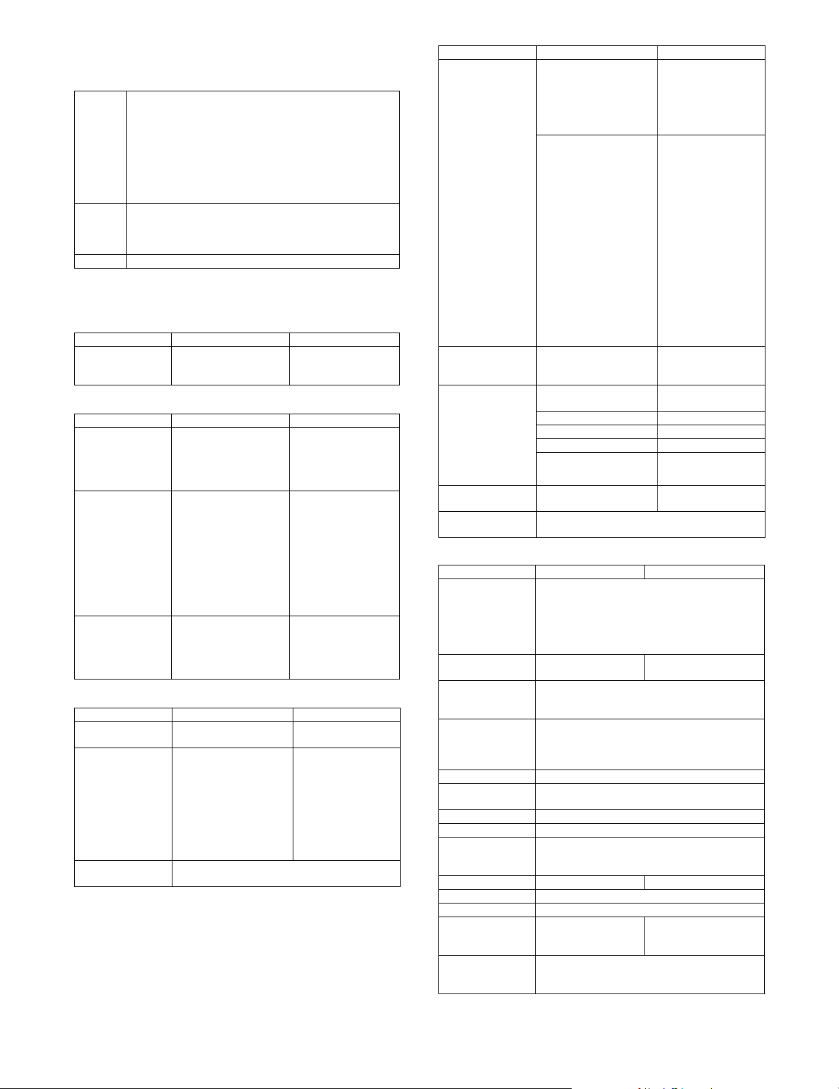
(8) Print functions
Function Content PCL6/5c PS (Option)
Multiple Pamphlet Binds multiple pamphlet outputs into a single booklet. Yes Yes
Bar code font JetCAPS BarDIMM emulation Yes No
Network tandem print Two units connected via network can be used simultaneously for a printout. Yes Yes (Windows
Windows Cluster Print When a Windows server breaks down, a mirror server takes over and executes the suspended
Encryption PDF/PDF/
TIFF/JPEG direct print
E-Mail To Print Direct printing of an attached file upon receipt of the e-mail. Yes Yes
Pull print from front panel Browsing of FTP server from front panel and pull-printing of a specified file (direct printing). Yes Ye s
FTP PUSH print Performs direct print by data transfer from the client PC to the MFP server. Yes Yes
Print by file setup on Web
page [Web Submit Print]
Continuous print function The function executes multiple print jobs continuously as if they are one single job even if the
ROPM The function enables the printout of a multiple number of copies in one RIP processing. Yes Yes
Multi-access RIP processing must be allowed during printing. Printing must also be allowed during scanning. Yes Yes
Paper direction setting for
2-sided printing of
letterhead paper and prepunched paper.
Enable selected paper
type in bypass tray
Setting environmental
control under terminal
server control
Driver delivery function PAU4.0 allows the administrator to deliver a driver to clients. Yes Yes
Form overlay The function downloads a form to the main unit beforehand, sends the contained data only, and
Planet Press Object Lune Corporation's Planet Press (Software to execute the mapping of forms (DL
Improvement of
downloading method of
font form
Management of password
by hidden Web page
Expansion font list In self-print of a font list, ESC command information is needed for BITMAP font. Yes
Bonjour for Macintosh
environment
Document control When printing, the unique pattern for prevention against unauthorized copy
Object judgement (screen
change/color change)
CMYK Simulation Choice of CMYK simulation is as follows.
ICC Profile <Source Profile>
Pantone color For Pantone color support, the profile upload can be made by Web setting. No Yes
print job.
* There may be color differences between machine types
PDF/TIFF/JPEG file can be printed without printer driver.
1) Printing of e-mail attachment file
2) Printing from FTP server
3) Printing from setup file on Web page
4) USB memory
Setting and direct printing of a file on network through Web page. Yes Yes
unit receives an end of job command, in order to support print from the application assuming
printout on continuous pages.
Pages with front-back attribute such letterhead or punch paper are to be printed correctly in
front-back page order for 2-sided printing.
For setting of bypass tray, even if the setup values on the main unit side do not match with those
on the driver side, the printing will be executed in the setting of the driver regardless of the setup
values on the main unit side.
Print setting of each client is memorized under meta frame environment (auto print create
environment). (Setup for each log-in can be skipped.)
inserts the data into the form in the main unit for printout.
beforehand) and variable data in the printer interior)
This expands the function to prevent the deletion and overwriting of the editing functional
enhancement font/form on Web page. A unified UI for the lineup is necessary.
Currently, registration is done by Web page and deleted by PJL. This function is supported by
HDD.
The purpose is to prevent the access even if the hidden Web page address becomes known. Yes Yes
This technology detects and connects peripheral equipment on the network automatically.
The dynamic network connection (computer, peripheral equipment and software) is possible
without user setting.
is embedded in printing.
In the printer color mode output, object of image data (area of photograph/graphic text) is
judged. Print screen (resolution) and profile (color) are changed automatically.
1) Default
2) Custom
Default is defined depending on the destination of service simulation.
1. Japan = Japan Color
2. North America / China / Other abroad inch type = SWOP
3. Europe / Other abroad AB type = Euroscale
Custom profile can upload by Web setting. Notation of driver is Custom.
Example: Use SWOP profile in Japan.
Choice of source profile is as follows.
•sRGB
• AppleRGB
•Custom
Custom profile can upload by Web setting. (The attached ICC profile on devices is available.)
<Output Profile>
There is no user selection for output profile. Sharp provides Custom profile. Upload of profile
supports by service. The tool is set on the Web (service setting). The concrete method of profile
making is to be considered separately.
Yes Yes (Windows
Yes (No for
encrypted
PDF/PDF)
Yes Ye s
Yes Ye s
Yes Ye s
Yes Ye s
Yes
(5c only)
Yes Ye s
Yes
(5c only)
(5c only)
No Yes
Yes (OPT) Yes (OPT)
PCL6: Yes
PCL5: No
No Yes
Yes Ye s
only)
only)
Yes
No
Yes
No
Yes
MX3500N SPECIFICATIONS 2 – 11
Page 19
(9) Windows driver function
PCL5-c/6: Standard
PS: Option (Installation of the PS3 expansion kit (MX-PKX1) are
required.)
a. Frequently used functions
Function PCL5-c/6 PS PPD
Copies (Copy
processing by
MFP/Printer
firmware)
Orientation Portrait/Landscape
Duplex 2-Sided (Book)
Pamphlet
(Pamphlet
processing by
MFP/Printer
firmware)
Binding Edge Top/Left/Right N/A
N-Up Printing 1-Up, 2-Up, 4-Up, 6-Up,
Black N-Up
Border
N-Up Order [2-Up]
2-Up Pamphlet N/A
Multiple 2-Up Pamphlet
Multiple Tiled Pamphlet
8-Up, 9-Up, 16-Up
Yes /N o N /A
d. Exposure
1-999
2-Sided (Tablet)
Tiled Pamphlet
(Windows NT: N/A)
(Windows 9x:
1-Up/2-Up/4-up)
Left to Right
Right to Left
[4, 6, 8, 9, 16-Up]
Right, and Down
Down, and Right
Left, and Down
Down, and Left
b. Paper feed system
Function PCL5-c/6 PS PPD
Paper Size A2 (Fit To Page)
Paper Selection Paper Source
Different Paper Cover Page N/A
Transparency
Inserts
Tab Printing Image Shift N/A
Set Tray Status Set Paper Size
Paper Type
Name (USER
TYPE 1-7)
Input Tray
Options
(PCL6 only)
12 x 18, A3, A4, A5, B4, B5, 11 x 17, 8.5 x 11, 8.5 x 14,
7.25 x 10.5, 8.5 x 13, 5.5 x 8.5, 8K, 16K, DL, C5,
COM10, Monarch, Custom Paper
Paper Type
Last Page N/A
Other Page N/A
Tab Paper
Printing
(PCL6 only)
Set Paper Type
Display Name N/A
Two Trays/Three Trays/Four
Trays
N/A N/A
Auto Selection/
Paper Source /
Paper Type
Blank/Printed
N/A
N/A
N/A
c. Paper exit method
Function PCL5-c/6 PS PPD
Output Tray Center Tray/Right Tray/Offset Tray/Saddle
Staple None/1-Staple/2-Staples
Punch Yes/No
No Offset Yes/No
Large Capacity Tray None/MX-LCX1
Output Tray Options None/Finisher/Saddle Stitch Finisher
Punch Module None/2 Holes/3 Holes/4 Holes/4 Holes (Wide)
Right Tray Yes/No
Stit ch Tray
Resolution 600 x 600dpi
Color Mode Auto/Color(CMYK)/Monochrome (K only)
ICM Method (Cannot be specified
with the monochrome mode)
Rendering Intent (Cannot be
specified with the monochrome
mode)
ICC Profile Selection (Cannot be
specified with the monochrome
mode)
Print Priority (Cannot be specified
with the monochrome mode)
Contrast
* Some OS may not allow one-
number-to-next specification for
setup values.
Brightness
* Some OS may not allow one-
number-to-next specification for
setup values.
Function PCL5-c/6 PS PPD
300 x 300dpi
N/A OFF OFF
System (Windows ICM). Effective only when Color Options is Custom.
Printer Printer
N/A N/A
When ICM Method is anything other than Custom: Default
When ICM Method is Custom:
Perceptual matching
Relative colorimetric
Saturation matching
Absolute colorimetric
Source Profile (Monitor Profile)
When Windows ICM is off:
None
sRGB
Apple RGB
Custom
When Windows ICM is on:
Monitor Profile installed in PC
1 bit or 2 bit 1 bit or 2 bit
2 bit or 4 bit 2 bit or 4 bit
0-100 N/A
0-100 N/A
1200 x 600dpi
(monochrome only)
600 x 600dpi
Windows NT: N/A
600 x 600dpi
Perceptual matching
Relative colorimetric
Saturation matching
Absolute colorimetric
Source Profile (Monitor Profile)
sRGB
Apple RGB
Custom
MX3500N SPECIFICATIONS 2 – 12
Page 20
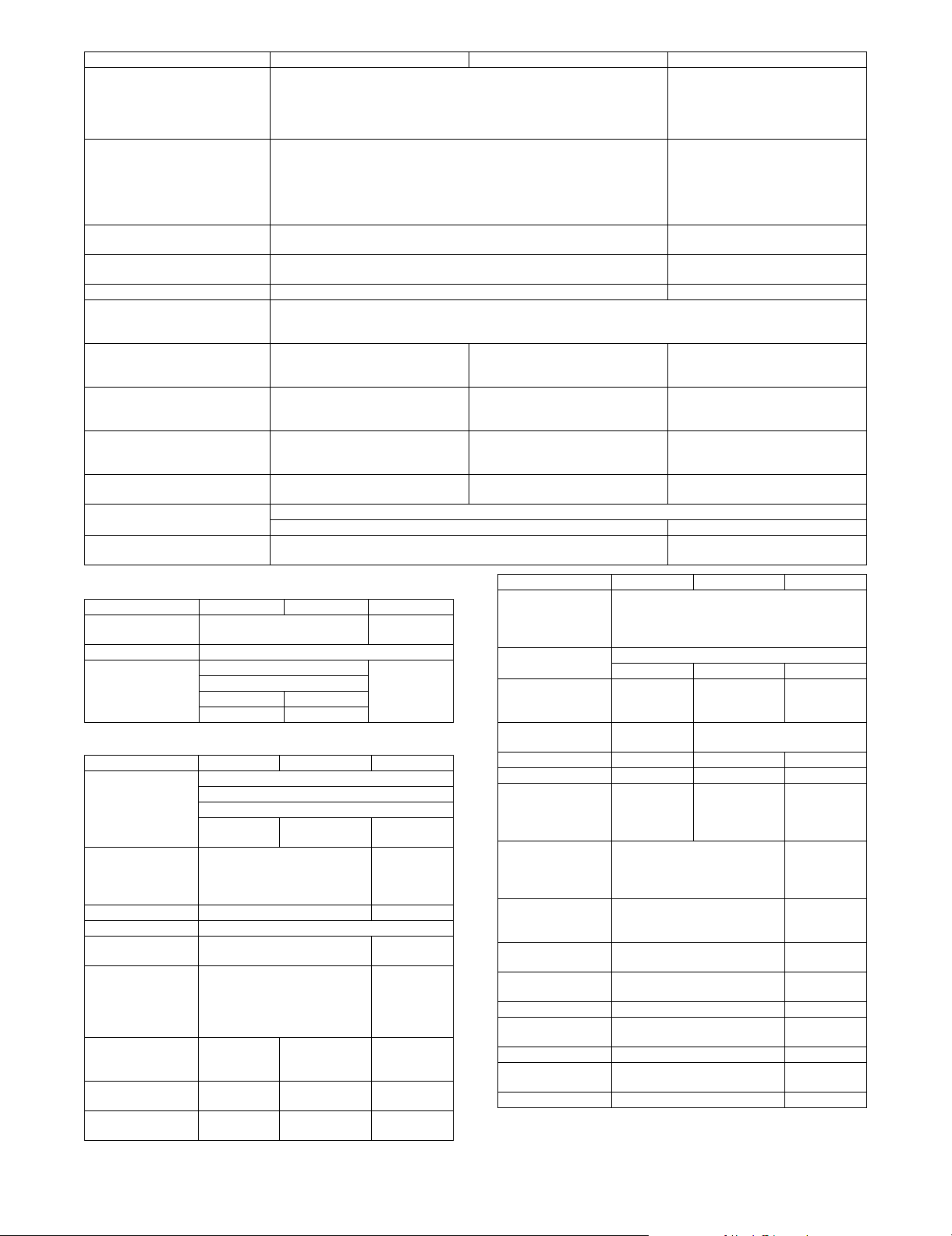
Function PCL5-c/6 PS PPD
Saturation (Cannot be specified
with the monochrome mode)
* Some OS may not allow one-
number-to-next specification for
setup values.
Color Balance (RGB)
(Cannot be specified with the
monochrome mode)
* Some OS may not allow one-
number-to-next specification for
setup values.
Text To Black (Can be specified only
with the monochrome mode)
Vector To Black (Can be specified
only with the monochrome mode)
Toner Save (1bit only) Yes/No Yes/No
Screen Setting (Cannot be specified
with the monochrome mode)
Pure Black Print (Cannot be
specified with the monochrome
mode)
Black Overprint (Cannot be
specified with the monochrome
mode)
CMYK Simulation (Cannot be
specified with the monochrome
mode)
Bitmap Compression None
Image Type Standard/Graphics/Photo/Custom
Neutral Grays (Cannot be specified
with the monochrome mode)
N/A Yes/No Yes/No
N/A Yes/No Yes/No
N/A Yes/No
(PCL6 only)
e. Font
Function PCL5-c/6 PS PPD
Font Source Resident Font
Download Font
Font Substitution N/A
Download Font Type TrueType (Type 42) Yes
Bitmap (Type 3)
N/A Adobe (Type1)
As Graphics N/A
N/A
f. Other functions
Function PCL5-c/6 PS PPD
Watermark Transparent Text
Overwrite Text
Outline Text
Yes
(PCL6 only)
Overlay Create Overlay
Query Page Overlay
Rotate 180 degrees Yes/No Yes/No
Collate Yes/No
Carbon Copy Top Copy
Fit To Page A3, A4, A5, B4, B5, 11 x 17, 8.5 x
8.5 x 14, 7.25 x 10.5/8.5 x 13/5.5
x 8.5, 8K, 16K, DL, C5, COM10,
Poster 2 x 2/3 x 3/
4 x 4
(PCL6 only)
Poster Dash Border Yes/No
(PCL6 only)
Poster Overlap Yes/No
(PCL6 only)
Image Stamp N/A
Load Overlay
Delete
Carbon Copy
N/A
11,
Monarch
2 x 2/3 x 3/4 x 4 N/A
Yes/No N/A
Yes/No N/A
0-100 N/A
0-100 N/A
Yes/No N/A
Yes/No N/A
Default
Photo
Text & Graphic
In case of Yes:
Default /Custom
None N/A
CAD CAD
Black Only
4-Color
Function PCL5-c/6 PS PPD
Margin Shift (Margin
Shift processing by
MFP/Printer
firmware
Zoom 25% – 400%
Mirror Image N/A No Mirror Image
Graphics Mode Vector /
PS Pass Through N/A Yes/No
PS Error Printing N/A Yes/No Yes/No
Job Compression N/A None/Fastest/
Retention Hold Only
Document Filing Quick File
User Authentication Login Name
Job ID User Name
Notify Job End Yes/No N/A
Auto Job Control
Review
Tandem Print Yes/No
Set Tandem Print IP Address (Slave Machine)
Auto Configuration Yes N/A
None/10mm (0.4 inch)/20mm (0.8 inch)/30mm
N/A X-Y Zoom
Raster
Hold After Printd
Sample Print
Password
Main Folder
Custom Folder
Password
Job Name
Yes/No N/A
Default/Custom
Black Only
(1.2 inch)
Verti cal
Horizontal
Fast/Medium/
Best
Compression
4-Color
Off/
None
Verti cal
Horizontal
N/A
N/A
N/A
N/A
N/A
MX3500N SPECIFICATIONS 2 – 13
Page 21

(10) Macintosh driver functions
a. Frequently used functions
Function OS9 PPD OSX 10.1 OSX 10.2/3/4
Copies 1-999
Orientation Portrait/Landscape
Duplex 2-Sided (Long)
Pamphlet (Pamphlet
processing by MFP/
Printer firmware)
Binding Edge Top/Left/Right N/A Top/Left/Right
N-Up Printing 1-Up/2-Up/4-Up/6-Up/9-Up/16-Up
N-Up Border Yes/No
N-Up Order [2-Up]
b. Paper feed method
Function OS9 PPD OSX 10.1 OSX 10.2/3/4
Paper Size Setting 12 x 18, A3, A4, A5, B4, B5, 11 x 17, 8.5 x 11,
Paper Selection Auto Select
Different Paper Cover Page
Transparency Inserts Blank/Printed
Tab Printing N/A
Set Tray Status N/A
Paper Type Name
(USER TYPE 1-7)
Input Tray Options Two Trays/
8.5 x 14, 7.25 x 10.5, 8.5 x 13, 5.5 x 8.5, 8K,
16K, DL, C5, COM10, Monarch, Custom Paper
Three Trays/
Four Trays
c. Paper exit method
Function OS9 PPD OSX 10.1 OSX 10.2/3/4
Output Tray Center Tray/Right Tray/Offset Tray/Saddle
Staple None/1-Staple/2-Staples
Punch Yes/No
No Offset Yes/No
Large Capacity Tray None/MX-
Output Tray Options None/
Punch Module None /
Right Tray Yes/No N/A Yes/No
LCX1
Finisher/
Saddle Stitch
Finisher
2 Holes /
3 Holes /
4 Holes /
4 Holes
(Wide)
d. Exposure
Function OS9 PPD OSX 10.1 OSX 10.2/3/4
Resolution 600 x 600dpi
Color Mode Auto/Color (CMYK) /Monochrome (K only)
ICM Method ColorSync
(Cannot be specified
with the monochrome
mode)
* Specification
depending on OS
OFF N/A OFF
System N/A System
2-Sided (Short)
Tiled Pamphlet
Multiple Tiled Pamphlet
(Only more than 10.2)
Left to Right
Right to Left
[4, 6, 8, 9, 16-Up]
Right, and Down
Down, and Right
Left, and Down
Down, and Left
Paper Source
Paper Type
Yes
N/A Two Trays/
Three Trays/
Four Trays
Stitch Tray
N/A None/MX-
LCX1
N/A None /
Finisher/
Saddle Stitch
Finisher
N/A None /
2 Holes /
3 Holes /
4 Holes /
4 Holes
(Wide)
(10.3 only)
Printer
Function OS9 PPD OSX 10.1 OSX 10.2/3/4
Rendering Intent
* Specification
depending on OS
ICC Profile Selection
(Cannot be specified
with the monochrome
mode)
* Specification
depending on OS
Print Priority
(Cannot be specified
with the monochrome
mode)
Contrast
* Some OS may not
allow one-number-tonext specification for
setup values
Brightnesst
* Some OS may not
allow one-number-tonext specification for
setup values
Saturationt
(Cannot be specified
with the monochrome
mode)
* Some OS may not
allow one-number-to-
next specification for
setup values
Color Balance (RGB)
(Cannot be specified
with the monochrome
mode)
* Some OS may not
allow one-number-to-
next specification for
setup values
Tex t To B l a ck N/ A
Vector To Black N/A
Toner Save (1bit only) Yes/No
Screen Setting
(Cannot be specified
with the monochrome
mode)
Pure Black Print
(Cannot be specified
with the monochrome
mode)
Black Overprint
(Cannot be specified
with the monochrome
mode)
CMYK Simulation
(Cannot be specified
with the monochrome
mode)
Bitmap Compression N/A
Image Type Standard/Graphic/Photo/CAD/Custom
Neutral Grays
(Cannot be specified
with the monochrome
mode)
Source
Profile
(Monitor
Profile)
sRGB
Apple RGB
Custom
Perceptual matching
Relative colorimetric
Saturation matching
Absolute colorimetric
N/A Source
Profile
(Monitor
Profile)
sRGB
Apple RGB
Custom
(10.3 only)
1 bit or 2 bit
2 bit or 4 bit
N/A
N/A 0-100
N/A 0-100
N/A
Default
Photo
Test & Graphic
Yes /N o
Yes /N o
Off
Default
Custom
Black Only
4-Color
e. Font
Function OS9 PPD OSX 10.1 OSX 10.2/3/4
Font Source (Resident
Font/Download Font)
Font Substitution N/A
Download Font Type Yes N/A
N/A
MX3500N SPECIFICATIONS 2 – 14
Page 22
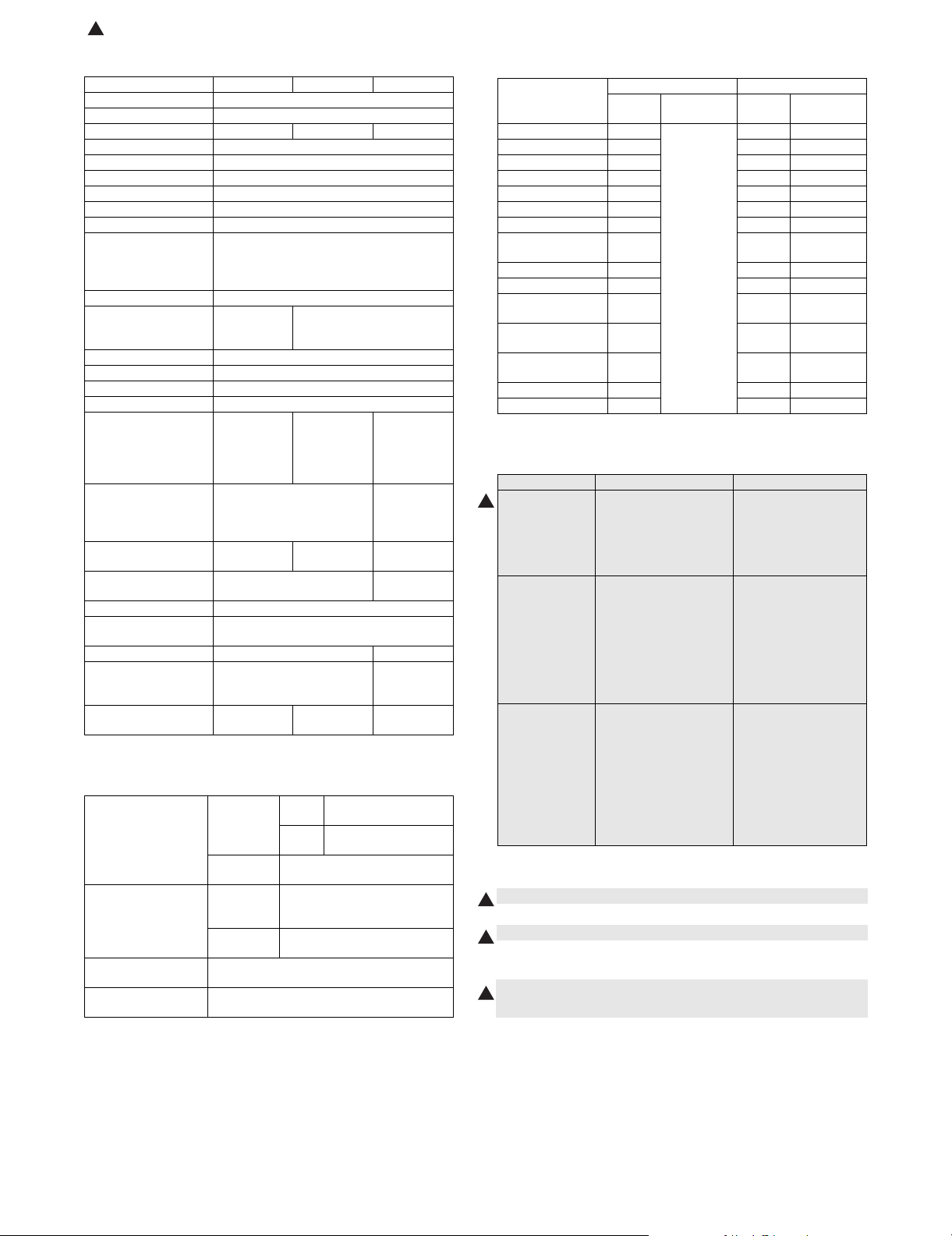
: Nov. 15 2007
9
f. Other functions
(2) Data saving for each function
Function OS9 PPD OSX 10.1 OSX 10.2/3/4
Watermark Transparent Text/Overwrite Text/Outline Text
Overlay N/A
Rotate 180 degrees Yes/No N/A Yes/No
Collate Yes/No
Carbon Copy N/A
Fit To Page N/A
Poster N/A
Black Poster Border N/A
Poster Overlap N/A
Margin Shift
(Margin Shift
processing by MFP/
Printer firmware
Zoom 25% – 400%
Mirror None
Graphics Mode N/A
PS Pass through N/A
PS Error Printing Yes/No
Job Compression N/A
Retention Hold Only,
Document Filing N/A Quick File
User Authentication Login Name
Job ID N/A User Name
Notify Job End N/A
Auto Job Control
Review
Tandem Print N/A Yes/No
Set Tandem Print N/A IP Address
Auto Configuration Yes N/A Yes
None/10mm/20mm/30mm (1.2inch)
Vert ical
Horizontal
N/A Hold Only,
Hold After
Print, Sample
Print, Pass
Code
N/A Login Name
Password
N/A
N/A
Hold After
Print, Sample
Print, Pass
Code
Main Folder
Custom
Folder
Password
Job Name
(Slave
Machine)
(10.3 only)
F. Document filing function
(1) Basic function
Capacity for document
filing
Pages or files for
allowed for filing
Maximum number of
user folder
Number of users
allowed for registration
Main folder
Custom
folder
Quick file
folder
Main folder
Custom
folder
Quick file
folder
Maximum of 500 folders
Depends on the number of user registrations.
(Maximum of 200 users)
RSPF
10GB
model
DSPF
30GB
model
10GB
10GB: 1,400 pages or 1,000 files
30GB: 4,200 pages or 3,000 files
(SHARP standard document)
1,400 pages or 1,000 files
(SHARP standard document)
Job
Co py Ye s No Yes Ye s
Printer Yes Yes Yes
Direct print (FTP) Yes No No
Direct print (e-mail) Yes Yes No
Direct print (Web) Yes No No
Scan to e-mail/FTP Yes Yes No
Scan to SMB --- --- ---
Scan to USB
memory
Fax reception No No No
Fax transmission Yes Yes No
Internet Fax
reception
Internet Fax
transmission
PC-Fax/PC-Internet
Fax transmisson
Remote PC Scan --- --- ---
Scan to HDD No Yes Yes
Quick File Folder Main/Custom Folder
Shared
storage
Confidential
storage
--- --- ---
No No No
Yes Yes N o
Yes Yes Yes
Shared
storage
G. Safety and environmental standards
(1) Safety standards
100V type 200V type
Safety standard Electrical safety law:
9
EMC ICES-003 Class A
Line standard (for
Fax expansion)
UL60950-1,
21CFR (Laser)
CSA C22.2 No. 60950-103
CNS14336 (Taiwan)
CNS 13438 Class B
Validation of Technology
Standard Conformance
(Electrical
Communications Project
Law)
FCC part 68
ICCS-03
PSTN01 (Taiwan)
AS/NZS 60950
(2) Environmental standards
• International Energy Star Program MFP (EPA)
9
• Environmental Choice Program (ECP)
9
•Nordic Swan
• European ROHS regulations
• Chinese ROHS (The machine shipped for China only)
9
• WEEE (The machine shipped for Europe only)
EN60950-1
IEC60825-1 (Laser)
IEC60950-1
GB4943 (China)
EN55022 Class A
CISPR22 Class A
AS/NZS CISPR 22 Class
A
EN55024
EN61000-3-2
EN61000-3-3
GB9254 Class A,
GB17625.1
TS 103 021 or TBR21,
EG 201 120, EG 201 121
(Europe)
AS/ACIF S0002
(Australia)
GB/T 3382.1,
GB/T 3382.2, YD/T 514,
YD/T 589, YD/T 703,
YD/T 965, YD/T 993
(China)
Confidential
storage
MX3500N SPECIFICATIONS 2 – 15
Page 23
: Nov. 15 2007
9
3. Ambient conditions
A. Operating environmental conditions
(Main unit)
Temperature: 10qC – 35qC, Humidity: 20 – 85%RH
Air pressure: 590 – 1013hPa (height: 0 – 2000m)
Humidity (RH)
85%
60%
20%
B. Ambient conditions for transporting
(Main unit)
–20qC to 45qC (No condensation)
Humidity (RH)
90%
60%
20%
C. Operating environmental conditions (Supply)
9
Humidity (RH)
85%
60%
20%
D. Ambient conditions for transporting
–20qC to 45qC (No condensation)
E. Environmental conditions for storing
unopened consumable parts
–10qC to 40qC (No condensation)
F. Standard storage period of unopened
consumable parts
1) Photoconductor drum
36 months from the production month (production lot)
2) Developer
24 months from the production month (production lot)
3) Toner (K/C/M/Y)/Developer (K/C/M/Y)
24 months from the production month (production lot)
MX3500N SPECIFICATIONS 2 – 16
Page 24
MX3500N
[3] CONSUMABLE PARTS
5GTXKEG/CPWCN
1. Supply system table
A. USA/Canada/South and Central America
No. Item Content Life Model Name Remarks
1 Toner Cartridge (Black) Toner Cartridge (Black) with IC Chip
2 Toner Cartridge (Cyan) Toner Cartridge (Cyan) with IC Chip
3 Toner Cartridge (Magenta) Toner Cartridge (Magenta) with IC Chip
4 Toner Cartridge (Yellow) Toner Cartridge (Yellow) with IC Chip
5 Developer (Black) Developer (Black)
6 Developer
(Cyan/Magenta/Yellow)
7 Drum OPC Drum x 1 150K (Black)
8 Drum Unit Drum Unit (OPC Drum/Unit Parts included)
(Black toner : Net 880g)
(Cyan toner : Net 352g)
(Magenta toner : Net 352g)
(Yellow toner : Net 352g)
(Black developer : Net 270g)
Developer (Cyan/Magenta/Yellow)
(Cyan/Magenta/Yellow developer : Net 270g)
Color identification seal (Bk/C/M/Y) x 1 each
*1: The toner life may vary depending on the document density and temperature and humidity.
B. European Subsidiary/Australia/New Zealand
No. Item Content Life Model Name Remarks
1 Toner Cartridge (Black) Toner Cartridge (Black) with IC Chip
2 Toner Cartridge (Cyan) Toner Cartridge (Cyan) with IC Chip
3 Toner Cartridge (Magenta) Toner Cartridge (Magenta) with IC Chip
4 Toner Cartridge (Yellow) Toner Cartridge (Yellow) with IC Chip
5 Developer (Black) Developer (Black)
6 Developer
(Cyan/Magenta/Yellow)
7 Drum OPC Drum x 1 150K (Black)
8 Drum Unit Drum Unit (OPC Drum/Unit Parts included)
(Black toner : Net 880g)
(Cyan toner : Net 352g)
(Magenta toner : Net 352g)
(Yellow toner : Net 352g)
(Black developer : Net 270g)
Developer (Cyan/Magenta/Yellow)
(Cyan/Magenta/Yellow developer : Net 270g)
Color identification seal (Bk/C/M/Y) x 1 each
*1: The toner life may vary depending on the document density and temperature and humidity.
C. Asia-Subsidiary/Hong Kong
x 1 36K *1 MX-45NTBA * Life: A4/Letter size
x 1 15K *1 MX-27NTCA * Life: A4/Letter size
x 1 15K *1 MX-27NTMA * Life: A4/Letter size
x 1 15K *1 MX-27NTYA * Life: A4/Letter size
x 1 150K MX-27NVBA
x 1 100K MX-27NVSA
100K (Color)
x 1
150K (Black)
x 1
100K (Color)
x 1 36K *1 MX-45GTBA * Life: A4/Letter size
x 1 15K *1 MX-27GTCA * Life: A4/Letter size
x 1 15K *1 MX-27GTMA * Life: A4/Letter size
x 1 15K *1 MX-27GTYA * Life: A4/Letter size
x 1 150K MX-27GVBA
x 1 100K MX-27GVSA
100K (Color)
x 1
150K (Black)
x 1
100K (Color)
MX-27NRSA
MX-27NUSA
MX-27GRSA
MX-27GUSA
at Area Coverage 5%
(Reference: 30K for A4/Letter 6%)
at Area Coverage 5%
at Area Coverage 5%
at Area Coverage 5%
at Area Coverage 5%
(Reference: 30K for A4/Letter 6%)
at Area Coverage 5%
at Area Coverage 5%
at Area Coverage 5%
No. Item Content Life Model Name Remarks
1 Toner Cartridge (Black) Toner Cartridge (Black) with IC Chip
2 Toner Cartridge (Cyan) Toner Cartridge (Cyan) with IC Chip
3 Toner Cartridge (Magenta) Toner Cartridge (Magenta) with IC Chip
4 Toner Cartridge (Yellow) Toner Cartridge (Yellow) with IC Chip
5 Developer (Black) Developer (Black)
6 Developer
(Cyan/Magenta/Yellow)
7 Drum OPC Drum x 1 150K (Black)
8 Drum Unit Drum Unit (OPC Drum/Unit Parts included)
(Black toner : Net 880g)
(Cyan toner : Net 352g)
(Magenta toner : Net 352g)
(Yellow toner : Net 352g)
(Black developer : Net 270g)
Developer (Cyan/Magenta/Yellow)
(Cyan/Magenta/Yellow developer : Net 270g)
Color identification seal (Bk/C/M/Y) x 1 each
x 1 36K *1 MX-45ATBA * Life: A4/Letter size
x 1 15K *1 MX-27ATCA * Life: A4/Letter size
x 1 15K *1 MX-27ATMA * Life: A4/Letter size
x 1 15K *1 MX-27ATYA * Life: A4/Letter size
x 1 150K MX-27AVBA
x 1 100K MX-27AVSA
MX-27ARSA
MX-27AUSA
x 1
x 1
100K (Color)
150K (Black)
100K (Color)
at Area Coverage 5%
(Reference: 30K for A4/Letter 6%)
at Area Coverage 5%
at Area Coverage 5%
at Area Coverage 5%
*1: The toner life may vary depending on the document density and temperature and humidity.
MX3500N CONSUMABLE PARTS 3 – 1
Page 25
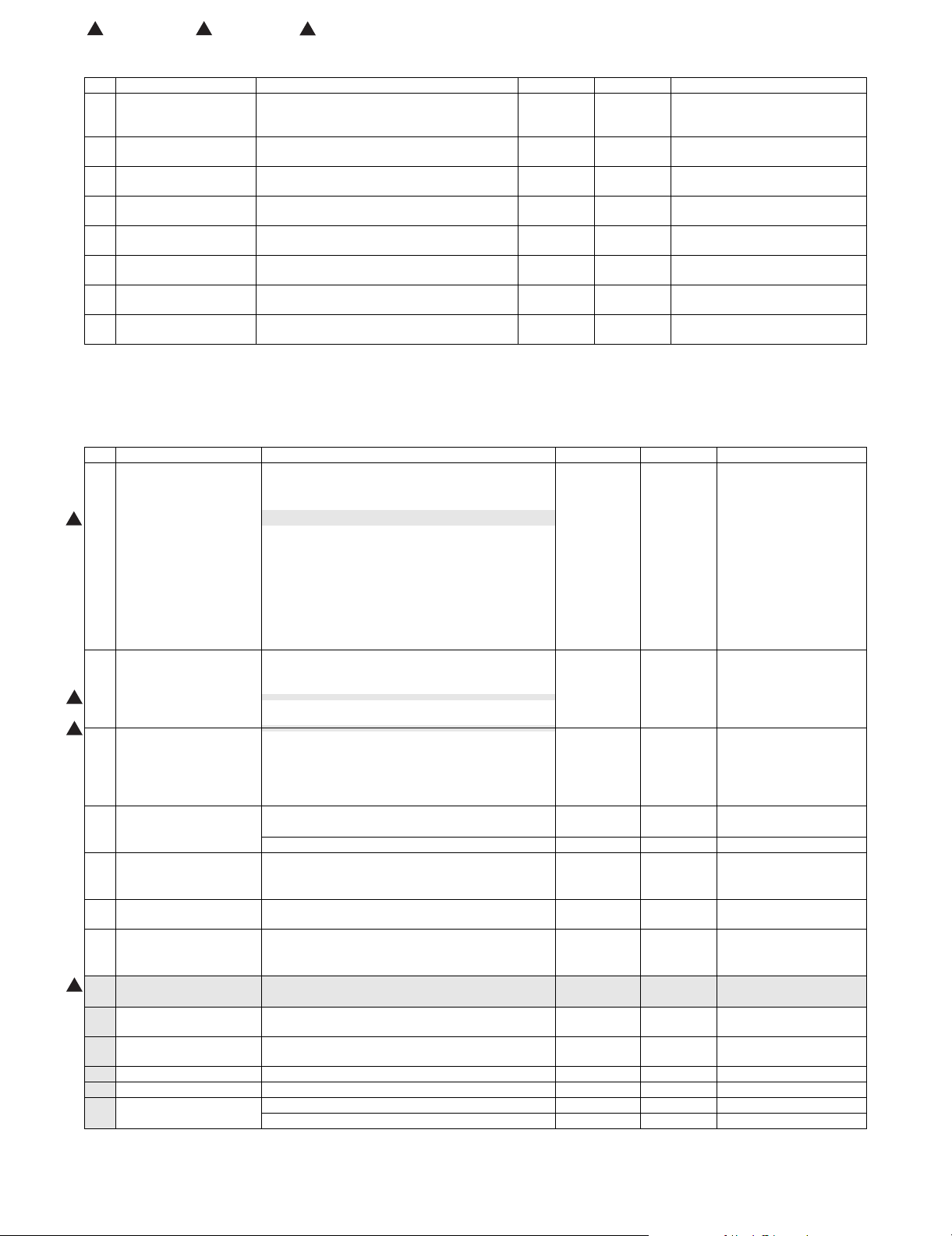
: Jan. 15 2006, : Jul. 15 2006, : Feb. 15 2007
1 5
7
D. Middle East/Africa/Israel/Philippines/Taiwan
No. Item Content Life Model Name Remarks
1 Toner Cartridge (Black) Toner Cartridge (Black) with IC Chip
2 Toner Cartridge (Cyan) Toner Cartridge (Cyan) with IC Chip
3 Toner Cartridge (Magenta) Toner Cartridge (Magenta) with IC Chip
4 Toner Cartridge (Yellow) Toner Cartridge (Yellow) with IC Chip
5 Developer (Black) Developer (Black)
6 Developer
(Cyan/Magenta/Yellow)
7 Drum OPC Drum x 1 150K (Black)
8 Drum Unit Drum Unit (OPC Drum/Unit Parts included)
(Black toner : Net 880g)
(Cyan toner : Net 352g)
(Magenta toner : Net 352g)
(Yellow toner : Net 352g)
(Black developer : Net 270g)
Developer (Cyan/Magenta/Yellow)
(Cyan/Magenta/Yellow developer : Net 270g)
Color identification seal (Bk/C/M/Y) x 1 each
x 1 36K *1 MX-45FTBA * Life: A4/Letter size
x 1 15K *1 MX-27FTCA * Life: A4/Letter size
x 1 15K *1 MX-27FTMA * Life: A4/Letter size
x 1 15K *1 MX-27FTYA * Life: A4/Letter size
x 1 150K MX-27FVBA
x 1 100K MX-27FVSA
MX-27FRSA
MX-27FUSA
x 1
x 1
100K (Color)
150K (Black)
100K (Color)
at Area Coverage 5%
(Reference: 30K for A4/Letter 6%)
at Area Coverage 5%
at Area Coverage 5%
at Area Coverage 5%
*1: The toner life may vary depending on the document density and temperature and humidity.
2. Maintenance parts list
A. U.S.A/Canada/South and Central America/Asia/Middle East/Agencies
No. Item Content Life Model name Remarks
1 Heat roller kit Upper heat roller x 1 300K MX-450HK
Fuser gear x 1
Upper separation pawl x 4
5
2 Primary transfer kit Intermediate transfer belt x 1 150K MX-450Y1
7
7
3 Secondary transfer kit Secondary transfer belt x 1 300K MX-450Y2
4 Filter kit Ozone filter x 1 150K MX-450FL For North America/South
5 Web cleaning kit Web unit x 1 150K MX-450WC
6 Waste toner box kit Waste toner box unit (with LSU cleaner x 3) x 1 40K MX-270HB Each color 5% coverage,
7 DV seal kit DV seal x 3 Black: 150K,
8 Main charger kit Main charger unit x 1 Black: 150K,
1
9 Staple cartridge Staple cartridge x 3 5000 times x 3 AR-SC2 For saddle finisher
10 Staple cartridge Staple cartridge x 3 5000 times x 3 MX-SCX1 For inner finisher
11 Primary transfer belt unit Primary transfer belt unit (For service rotation) x 1 — MX-450U1
12 Secondary transfer belt unit Secondary transfer belt unit (For service rotation) x 1 — MX-450U2
13 Fusing unit Fusing unit (For service rotation) (Heater lamp 120V) x 1 — MX-450FU1
Upper separation pawl SP-N x 4
Upper thermistor sub x 1
Upper thermistor side x 1
Upper thermistor CJ x 1
Upper heat roller bearing x 2
Lower heat roller x 1
Lower heat roller bearing x 2
Lower separation pawl/spring x 4
Lower thermistor x 1
Primary transfer blade x 1
Primary transfer conductive collar x 4
PS paper dust removal cleaner x 1
Bearing x 4
Secondary transfer roller x 1
Secondary transfer idle gear x 1
Primary transfer roller x 4
Belt drive gear x 1
Paper exit filter x 2
Ozone filter x 1 150K MX-270FLN For Asia/Agencies
Sub roller x 1
Sub roller bearing x 2
DV side seal F/R x 3
Toner filter x 3
Drum cleaning blade x 1
Fusing unit (For service rotation) (Heater lamp 230V) x 1 — MX-450FU
Color: 100K
Color: 100K
MX-270DS
MX-270MK
and Central America
color ratios 43%
(MX-FNX2)
(MX-FNX1)
MX3500N CONSUMABLE PARTS 3 – 2
Page 26
: Jan. 15 2006, : Jul. 15 2006, : Feb. 15 2007
1 5
7
B. Europe/UK/Australia/New Zealand/Taiwan
No. Item Content Life Model name Remarks
1 Upper heat roller kit Upper heat roller x 1 300K MX-450UH
Fuser gear x 1
Upper separation pawl x 4
5
2 Lower heat roller kit Lower heat roller x 1 300K MX-450LH
3 Primary transfer belt kit Intermediate transfer belt x 1 150K MX-450B1
7
7
4 Primary transfer roller kit Primary transfer roller x 4 300K MX-450X1
5 Secondary transfer belt kit Secondary transfer belt x 1 300K MX-270B2
6 Secondary transfer roller kit Secondary transfer roller x 1 300K MX-450X2
7 Filter kit Ozone filter x 1 150K MX-450FL For Europe/Oceania
8 Web cleaning kit Web unit x 1 150K MX-450WC
9 Waste toner box kit Waste toner box unit (with LSU cleaner x 3) x 1 40K MX-270HB Each color 5% coverage,
10 DV seal kit DV seal x 3 Black: 150K,
11 Main charger kit Main charger unit x 1 Black: 150K,
1
12 Staple cartridge Staple cartridge x 3 5000 times x 3 AR-SC2 For saddle finisher
13 Staple cartridge Staple cartridge x 3 5000 times x 3 MX-SCX1 For inner finisher
14 Primary transfer belt unit Primary transfer belt unit (For service rotation) x 1 — MX-450U1
15 Secondary transfer belt unit Secondary transfer belt unit (For service rotation) x 1 — MX-450U2
16 Fusing unit Fusing unit (For service rotation) (Heater lamp 230V) x 1 — MX-450FU
Upper separation pawl SP-N x 4
Upper thermistor sub x 1
Upper thermistor side x 1
Upper thermistor CJ x 1
Upper heat roller bearing x 2
Lower heat roller bearing x 2
Lower separation pawl/spring x 4
Lower thermistor x 1
Primary transfer blade x 1
Primary transfer conductive collar x 4
PS paper dust removal cleaner x 1
Bearing x 4
Belt drive gear x 1
Secondary transfer idle gear x 1
Paper exit filter x 2
Ozone filter x 1 150K MX-270FLN For Taiwan
Sub roller x 1
Sub roller bearing x 2
color ratios 43%
DV side seal F/R x 3
Toner filter x 3
Drum cleaning blade x 1
Fusing unit (For service rotation) (Heater lamp 100V) x 1 — MX-450FU2
Color: 100K
Color: 100K
MX-270DS
MX-270MK
(MX-FNX2)
(MX-FNX1)
MX3500N CONSUMABLE PARTS 3 – 3
Page 27
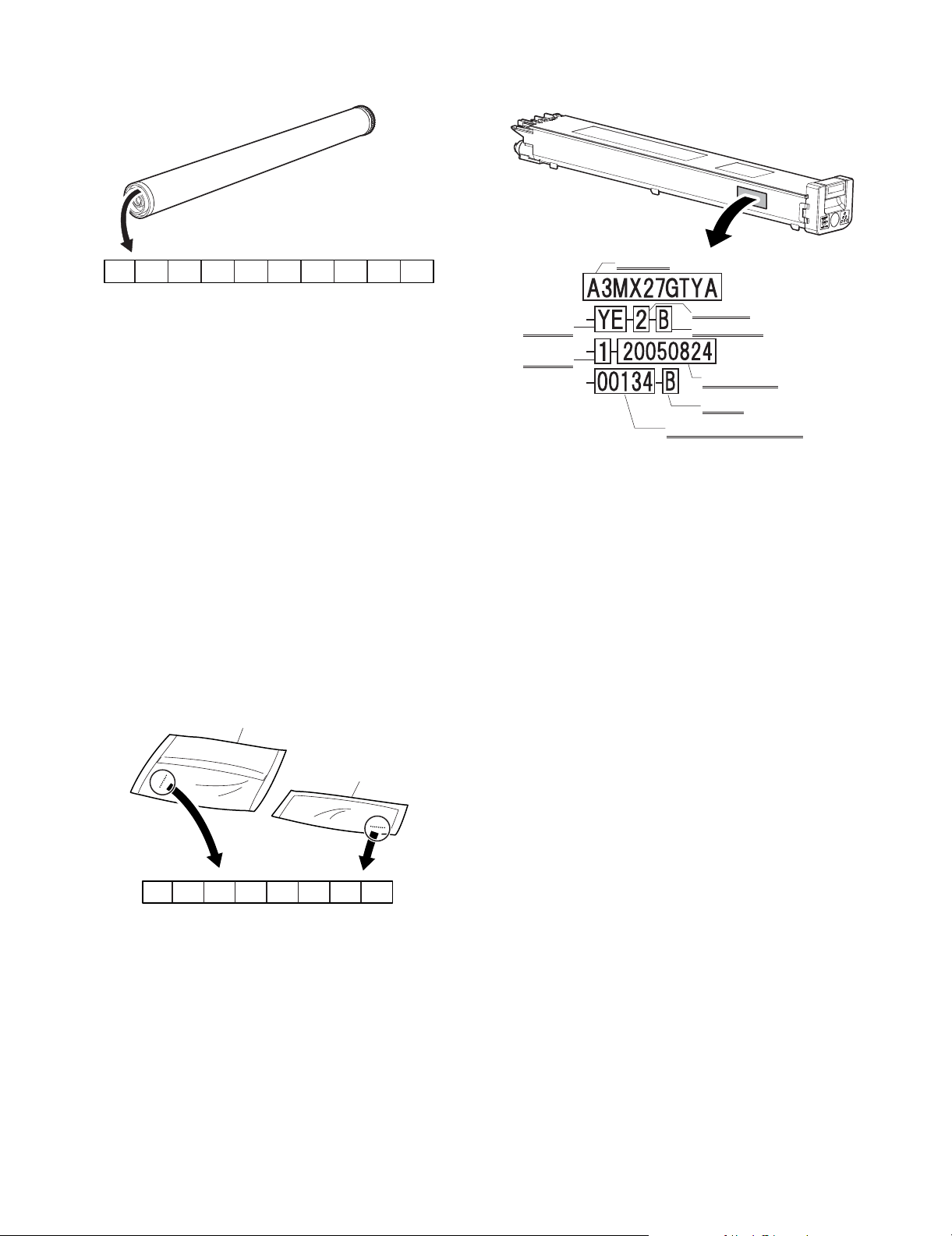
3. Production number identification
A. Drum cartridge
C. Toner cartridge
The label indicating the management number is attached to the
side of the toner cartridge.
1234 567 8 910
The lot number is of 10 digits. Each digit indicates the content as
follows.
The number is printed on the flange on the front side. The laser
print shows the production year and month.
1: Number
For this model, this digit is 2.
2: Alphabet
Indicates the model conformity code. H for this model.
3: Number
Indicates the end digit of the production year.
4: Number or X, Y, Z
Indicates the production month.
X stands for October, Y November, and Z December.
5/6: Number or X, Y, Z
Indicates the production month.
X stands for October, Y November, and Z December.
7: Number
Indicates the production month.
Indicates the day of the month of packing.
X stands for October, Y November, and Z December.
8/9: Number
Indicates the day of the day of packing.
10: Alphabet
Indicates the production factory. "C" for China.
B. Developer
Toner color
Production
place
Part name
Destination
Incompatibility
Production
year/month/day
Version
Serial No. in production day
Example: 134th of production on August 24, 2005
BK
C. M .Y
1234 567 8
The lot number is of 8 digits. Each digit indicates the content as follows.
The number is printed on the right under side of the back surface of
the developer bag.
1: Alphabet
Indicates the production factory.
2: Number
Indicates the production year.
3/4: Number
Indicates the production month.
5/6: Number
Indicates the production day.
7: Hyphen
8: Number
Indicates the production lot.
MX3500N CONSUMABLE PARTS 3 – 4
Page 28
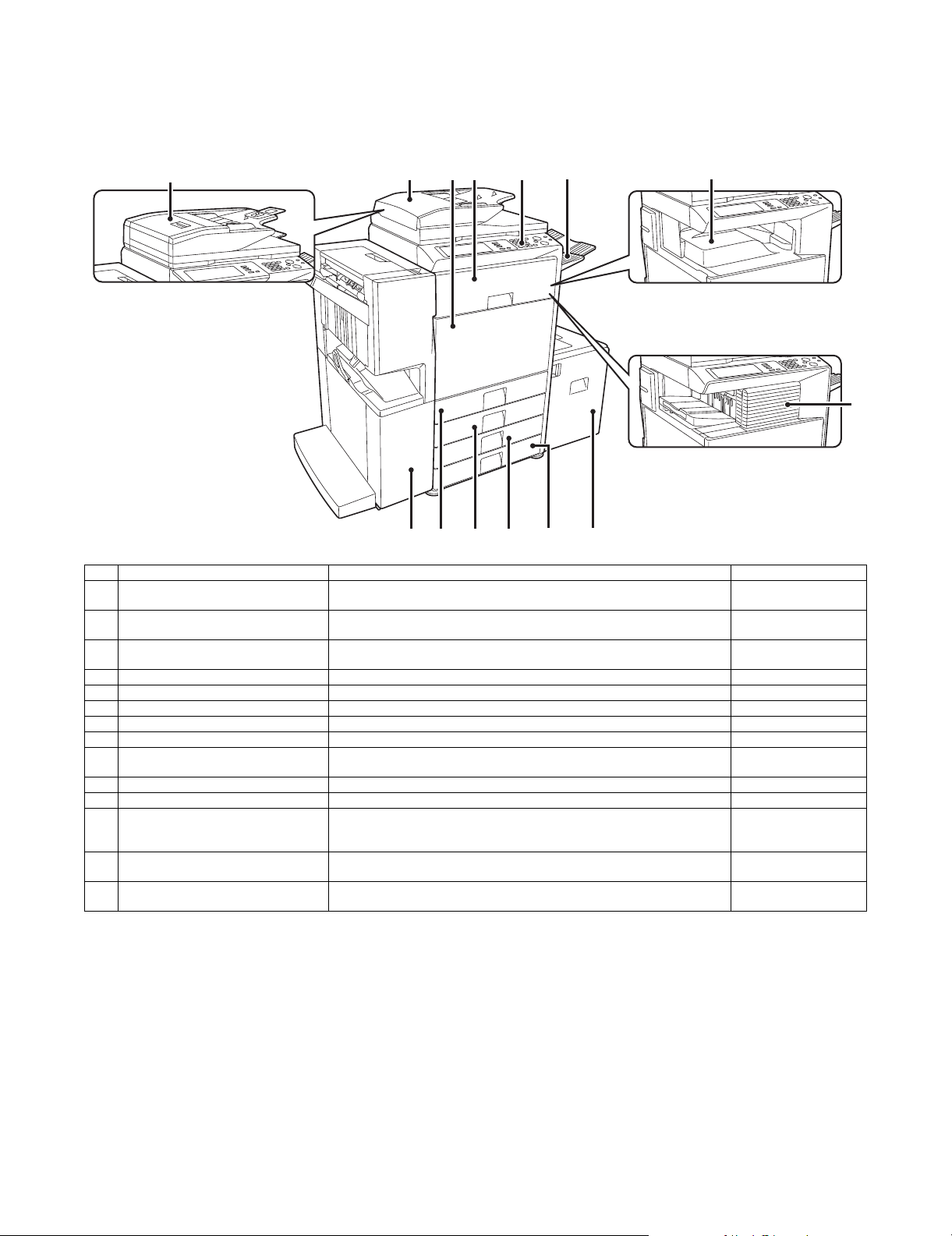
MX3500N
[5] EXTERNAL VIEW AND INTERNAL STRUCTURE
5GTXKEG/CPWCN
1. Identification of each section and functions
A. External view
1
When using the MX-3501N/4501N
4
3
2
6
5
When a finisher, paper pass unit and
7
saddle stitch finisher (peripheral
devices) are not installed.
When a finisher (peripheral
device) is installed.
9 1110 1412 13
No. Name Function/ Operation Note
1 Automatic document feeder
(Duplex single pass feeder)
2 Automatic document feeder
(Reversing single pass feeder)
3 Front cover Open this cover when turning ON/OFF the main power switch or replacing the
4 Interface unit *1 Feeds the output paper to the saddle finisher.
5 Operation panel Used to set the functions and enter the copy quantity.
6 Paper exit tray unit (Right tray) *1 Receives discharged paper if installed and set.
7 Paper exit tray (Center tray) Copied or printed paper is discharged to this tray.
8 Finisher *1 Staples paper, and makes punch holes if the punch unit is installed.
9 Saddle stitch finisher *1 Staples and outputs paper. It is also provided with the center-stapling function.
10 Tray 1 Stores paper. Max. 500 sheets (80g/m
11 Tray 2 Stores paper. Max. 500 sheets (80g/m
12 Tray 3 (When the stand/1 x 500 sheet
paper drawer or the stand/2 x 500 sheet
paper drawer is installed) *1
13 Tray 4 (When the stand/2 x 500 sheet
paper drawer is installed) *1
14 Tray 5 (When the large capacity paper
feed tray is installed) *1
*1: Peripheral devices
This automatically feeds and scans multiple originals. Both sides of two-sided
originals can be automatically scanned.
This automatically feeds and scans multiple originals. Both sides of two-sided
originals can be automatically scanned.
toner cartridge.
Makes punch holes if the punch unit is installed.
Stores paper. Max. 500 sheets (80g/m
Stores paper. Max. 500 sheets (80g/m
Stores paper. Max. 3500 sheets (80g/m
2
, 21lbs)
2
, 21lbs)
2
, 21lbs)
2
, 21lbs)
2
, 21lbs)
Installed standard on the
MX-3501N/4501N.
Installed standard on the
MX-3500N/4500N.
8
MX3500N EXTERNAL VIEW AND INTERNAL STRUCTURE 5 – 1
Page 29
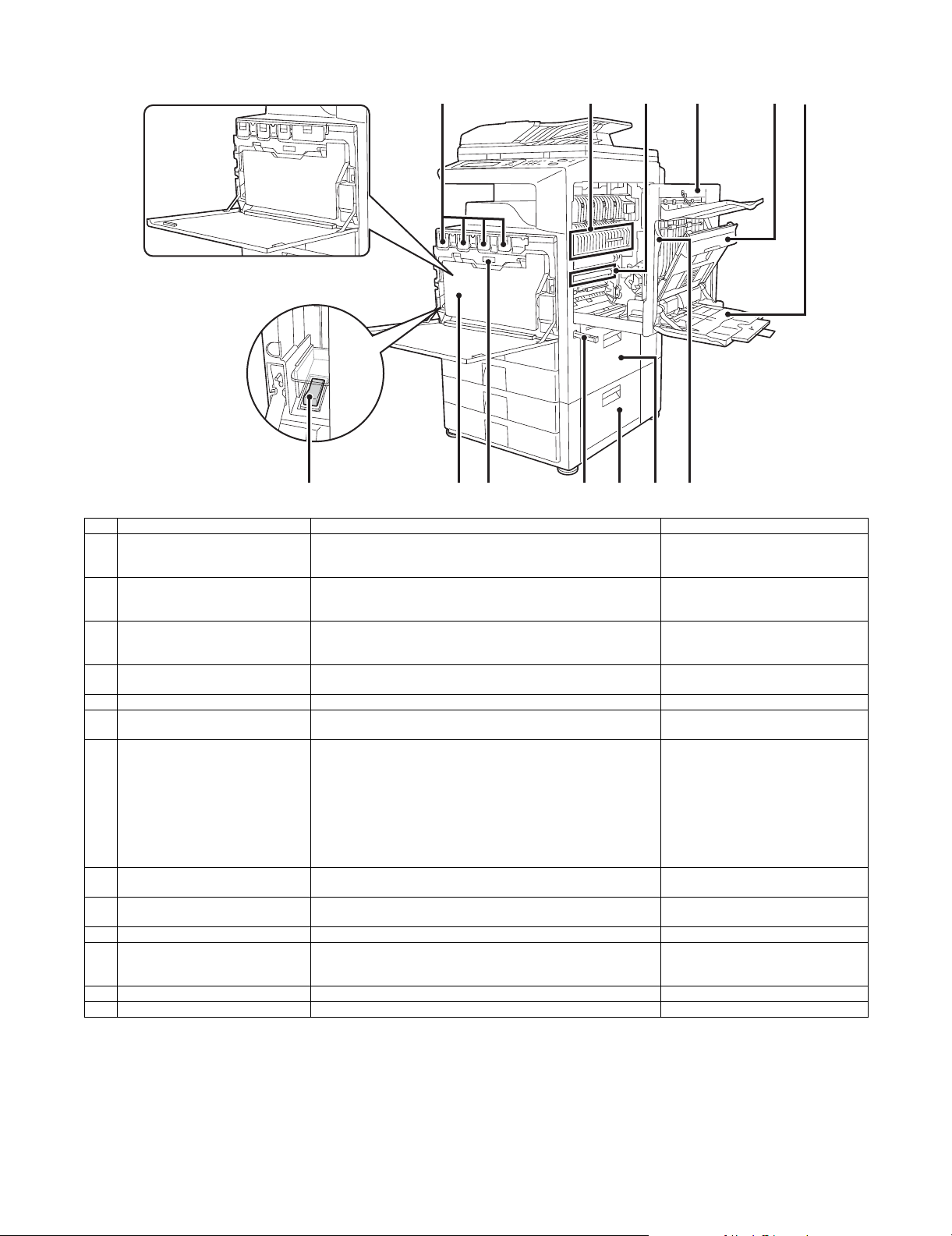
B. Internal structure
When using the MX-3500/4500 Series
1 2 3654
98 12 1311107
No. Name Function/ Operation Note
1 Toner cartridge When the toner in a cartridge runs out, the cartridge must be replaced
2 Fusing section Fuses images transferred on paper by heat. Note: The fusing section is heated to a
3 Transfer belt In full color copy, the transfer belt overlaps 4-color toner images on the
4 Right side cover This cover is opened to operate the fusing section pressure
5 Paper reverse section cover Used to reverse paper in duplex print or to remove a paper jam.
6 Manual feed tray In manual paper feed, paper is inserted from this tray. When paper
7 Main power switch Turns on the power of the machine. When FAX or internet is used,
8 Waste toner box Receives waste toner when copying or printing. The waste toner box is collected by the
9 Waste toner box release button Press this button to release lock of the waste toner box when replacing
10 Handle Used to lift the machine for transit.
11 2-stage paper feed desk right side
cover (When the 2-stage paper feed
desk is installed)
12 Paper feed tray right side cover Open this cover to remove a paper jam in the tray 1 or 2.
13 Right side cover open lever Lift this lever and open the right side cover to remove a paper jam.
with a new cartridge of the same color.
The shape of the toner cartridge varies slightly by model.
transfer belt. In black copy, black toner images are shifted to the
transfer belt.
adjustment lever or to remove a paper jam.
greater than A4R or 8-1/2” x 11” R, be sure to pull out the auxiliary tray.
keep it ON.
the waste toner box or cleaning the wiring unit.
Open this cover to remove a paper jam in the tray 3 or 4.
high temperature. Be careful not to burn
when paper jam.
Do not touch or scratch. It may cause
degraded images.
The main power lamp may remain ON
for about 1 minute after turning OFF the
main power switch. (When the main
power is turned OFF in the nighttime
FAX mode and OFF mode or when the
power outlet is disconnected. (This is
because the amount of electric charges
is great when only the resident power is
supplied.))
servicemen.
MX3500N EXTERNAL VIEW AND INTERNAL STRUCTURE 5 – 2
Page 30
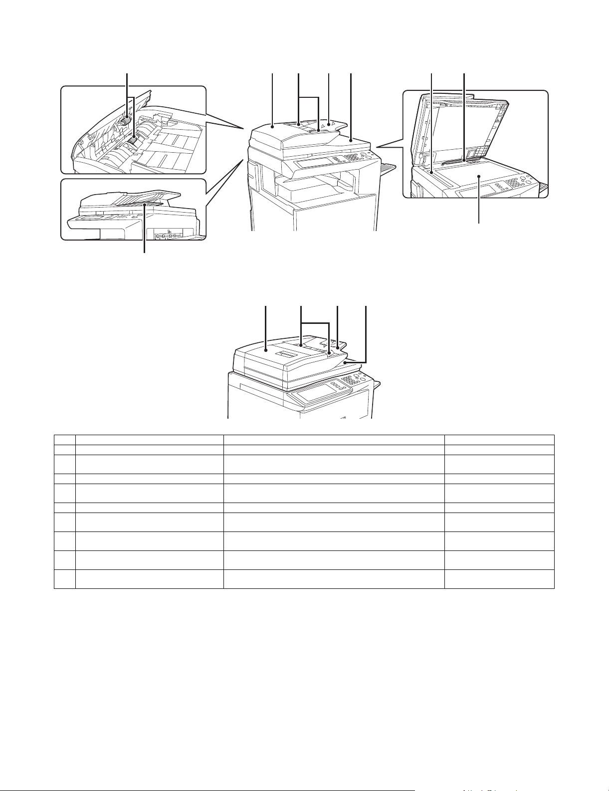
C. Automatic document feeder
• MX-3500N/4500N
8
• MX-3501N/4501N
2
3 4 5 6 71
23 45
9
No. Name Function/ Operation Note
1 Document feed roller Transports a document automatically.
2 Document feed section cover This cover is opened when removing a paper jam or cleaning the
3 Document guide Guides to scan a document properly. Set to the set document size.
4 Document set table A document is set on this table. In the case of a single-surface
5 Document exit section The scanned document is discharged to this section.
6 Document scan section The document set on the document set table is scanned in this
7 Document size detection plate Detects the size of a document set on the document table (glass
8 Document reverse tray When scanning a document, it is temporarily discharged to this
9 Document table (Glass surface) Used for thick documents or book documents which cannot be
document feed roller.
document, set it face up.
section.
surface).
section to be reversed for scanning the back surface.
entered to the auto document feeder.
NOTE: For the MX-3501N/4501N automatic document feeder (DSPF), refer to "00ZMX3501NS1E."
MX3500N EXTERNAL VIEW AND INTERNAL STRUCTURE 5 – 3
Page 31

D. Connectors
1
2
3
Service-only connector
No. Name Function/ Operation Note
1 USB connector (Type A) Used to connect a USB hub or USB memory.
2 USB connector (Type B) Used to connect a computer to use this machine as a printer.
3 LAN connector Used to connect a LAN cable to use this machine in a network.
MX3500N EXTERNAL VIEW AND INTERNAL STRUCTURE 5 – 4
Page 32

E. Operation panel
3 4521
DOCUMENT
FILING
IMAGE SEND
COPY
JOB STATUS
PRINT
READY
DAT A
LINE
DAT A
SYSTEM
SETTINGS
LOGOUT
76 8 9
10 1211 13 14 15 16
No. Name Function/ Operation Note
1 Touch panel A message or a key is displayed on the LCD screen. Touch the
displayed key with your finger to perform various operations. When the
displayed key is touched, a sound is generated and the selected item is
highlighted to confirm.
2 Mode select key/Lamp Used to switch the display mode of the touch panel. The lamp of the
selected key is lighted.
• [Document Filing] key
Press this key to switch to the document filing mode in order to store
a document to the hard disk in the form of a image or to print or send
the image stored in the hard disk.
• [FAX/Image send] key ([Image send] key for the models without the
FAX function)
Press this key to switch to the FAX mode/network scanner in order to
use the FAX function or the scanner function.
• Communicating lamp
This lamp is lighted during sending or receiving in the FAX mode, and
lighted during sending in the scanner mode.
• Data lamp
This lamp flashes when FAX data cannot be outputted due to paper
empty, etc. If there is data which has not been sent, the lamp is
lighted.
• [COPY] key
Press this key to switch to the copy mode in order to use the copy
function. When this key is pressed continuously, the total copy
quantity and the toner remaining quantity can be checked.
3 Printer lamp (Ready lamp/Data lamp) • Ready lamp
When this lamp is lighted, print data can be received.
• Data lamp
This lamp flashes during reception of print data, and lights up during
printing.
4 Numeric key (10-key) Used to enter the copy quantity or the FAX number, etc.
5 [C] key Used to clear the set value of copy quantity, etc. to “0.”
6 [Job status] key Press this key to display the job status. On the job status screen, the
details of the job can be checked and the job can be terminated.
7 [System setting] key When this key is pressed, the system setting menu screen is displayed
to allow the paper feed tray setting, destination registration, and other
setting for easy operations of this machine.
8 [Logout/Tone] key ([Logout] key for the
models without the FAX function)
Used to logout after user authentication. Used to deliver the tone signal
in the dial line when the FAX function is used.
9 [Program] key Used to use the job program when the copy function is used, and to dial
when the FAX function is used.
10 [CA] key Press this key to reset the operation, cancel setting, and start from the
initial state.
11 [STOP] key Used to stop copying and scanning a document.
12 [BLACK START] key Used to scan a document in black.
13 [COLOR START] key Used to make a color copy in the copy mode and to scan a document in
colors. When the FAX or the internet FAX is used, this key cannot be
used.
14 [Power save] key/Lamp Used to set the machine to the auto power shut off mode of power
saving. [Power save] key flashes in the auto power shut off mode.
15 [Power] key Turns ON/OFF the power of the machine.
Used in the FAX nighttime mode when the FAX is installed.
16 Main power lamp This lamp lights up when the main power switch of the machine is ON.
MX3500N EXTERNAL VIEW AND INTERNAL STRUCTURE 5 – 5
Page 33

F. Print and send status (Job status)
21
3
Complete job
status screen
JOB QUEUE SETS / PROGRESS STATUS
COPY
COPY
BBB BBB 020 / 000
0312345678 002 / 000
PRINT JOB
020 / 001
020 / 000
SCANNER
COPYING
PAPER EMPTY
WAITING
WAITING
4 5
SPOOL
JOB QUEUE
COMPLETE
DETAIL
PRIORITY
STOP/DELETE
INTERNET-FAXFAX JOB
6 97 8
No. Name Function/ Operation Note
1 Paper empty display Supply paper. If the status display indicates “Paper empty,” the specified size paper is
empty. In this case, if paper is not supplied, the output is reserved and the job data in
standby state which can be outputted are outputted in priority. (When, however, paper is
exhausted during outputting, the priority output of another job data is not made.)
To select another paper size for outputting because the specified size paper cannot be
supplied immediately, touch the key of the job in the job list and touch “8. [DETAIL] key,”
and the paper size specification can be changed.
2 Job list • The list of jobs reserved, during execution, or completed is displayed. When [PRINT] key
is touched with the mode select key, the display of the job status screen select key is
changed over to display the list of “SPOOL”. The list indicates the jog outline and the
status.
• When a print job during spooling or an encrypted PDF is directly printed, the job is
displayed on the “SPOOL” screen. If there is a list of encrypted PDF files, touch the job
key and enter the password, and the selected job is shifted to the list of [Reserve/
Executing], and the job enters the standby state.
3 Job status screen select key The job list display is switched to one of “SPOOL” job, “JOB QUEUE” job, or “COMPLETE”
job.
“SPOOL”: When an encrypted PDF is printed directly, the print job list is displayed. Can be
displayed when the print job is displayed.
“JOB QUEUE”: The job list which is reserved or executing is displayed.
“COMPLETE”: The job list which completed is displayed.
4 Mode select key Used to select the print mode, the scanner mode, the Fax mode, or the internet FAX mode.
• [PRINT JOB] key displays the list of copy, printer, Fax receive, internet Fax receive, and
the self print.
• [SCANNER] key displays the send list of the scanner function.
• [FAX JOB] key displays the send list of the Fax and the PC-Fax functions.
• [INTERNET FAX] key displays the send list of the internet Fax and the PC-Internet Fax
function.
5[p] [n] keys Selects the page of the displayed job list.
6 [STOP/DELETE] key Used to stop or delete the job which is executing or to delete a selected or reserved job.
However, the FAX receive print jog and the internet Fax receive print job cannot be stopped
or deleted.
7 [PRIORITY] key When a job is selected in the reserved jobs displayed in the job list of “JOB QUEUE” screen
and the key is touched, the job reservation priority is changed to the top priority.
For a print job, select a priority job and touch this key, and the previous copying or printing
is interrupted and the selected job copy or print is started. After completion of the selected
job, the interrupted job is resumed from the interrupted point.
8 [DETAIL] key Used to display the details of the selected job. When the automatic temporal save of the
document filing function or filing is executed, or when sequential broadcasting send is
executed with the FAX/image send function, the key display is made in the complete job
status screen. When this key is touched, the details of the completed jobs are displayed
and reprint or resend of the job can be executed by touching [CALL] key.
9 [CALL] key When the displayed key is touched on the complete job status screen and [CALL] key is
touched, the operation (reprint or resend) of the touched job is executed. Same as when
[DETAIL] key is touched and [CALL] key is touched.
SPOOL
JOB QUEUE
COMPLETE
DETAIL
CALL
INTERNET-FAX
MX3500N EXTERNAL VIEW AND INTERNAL STRUCTURE 5 – 6
Page 34

G. S en so rs
MHPS
TCS_Y
1TUD_CL
DHPD_CL
TCS_M TCS_C TCS_K
CSS1
CSS11
CSS13
CSS12
CSS14
CSS2
CSS21
CSS23
CSS22
CSS24
OCSW
1TUD_K
DHPD_K
CPED1
CPED2
TFD2
POD2
PPD2
PPD1
CLUD1
CSPD1
CLUD2
CSPD2
HPOS
POD1
REGS_F/R
PCS_CL/K
APPD2
MPFD
CPFD1
CPFD2
TFD3
POD3
APPD1
DSW_ADU
MPED
DSW_C
MPWD
MTOP1
TH_M/HUD_M
MTOP2
MPLD
Signal name Name Function/Operation Type NOTE
1TUD_CL Transfer belt separation CL detection Detects the transfer belt separation CL. Transmission type
1TUD_K Transfer belt separation BK detection Detects the transfer belt separation BK. Transmission type
APPD1 ADU transport path detection 1 Detects the duplex (ADU) upstream paper pass. Transmission type
APPD2 ADU transport path detection 2 Detects the duplex (ADU) midstream paper pass. Transmission type
CLUD1 Tray 1 upper limit detection (Lift HP
detection)
CLUD2 Tray 2 upper limit detection (Lift HP
detection)
CPED1 Tray 1 paper empty detection Detects tray 1 paper empty. Transmission type
CPED2 Tray 2 paper empty detection Detects tray 2 paper empty. Transmission type
CPFD1 Tray 1 transport detection (Paper entry
detection)
CPFD2 Tray 2 transport detection (Paper entry
detection)
CSPD1 Tray 1 paper remaining quantity detection Detects tray 1 paper remaining quantity. Transmission type
CSPD2 Tray 2 paper remaining quantity detection Detects tray 2 paper remaining quantity. Transmission type
DHPD_CL CL phase detection Detects the CL phase.
DHPD_K BK phase detection Detects the BK phase.
DSW_ADU ADU transport open/close detection Detects the duplex (ADU) cover open/close. Transmission type
DSW_C Tray 1 and 2 transport cover open/close
detection
HPOS Shifter home position detection Detects the shifter home position. Transmission type
MHPS Scanner home position sensor Detects the scanner home position. Transmission type
MPED Manual feed paper empty detection Detects the manual feed paper empty. Transmission type
MPFD Manual feed paper entry detection Detects the manual feed paper entry. Transmission type
MPLD Manual feed paper length detector Detects the manual paper feed tray paper length. Transmission type Manual paper
Detects tray 1 upper limit. Transmission type
Detects tray 2 upper limit. Transmission type
Detects tray 1 paper pass. Transmission type
Detects tray 2 paper pass. Transmission type
Detects the tray 1 and 2 transport cover open/close. Transmission type
feed unit
MX3500N EXTERNAL VIEW AND INTERNAL STRUCTURE 5 – 7
Page 35

Signal name Name Function/Operation Type NOTE
MPWD Manual paper feed tray paper width
detector
MTOP1 Manual paper feed tray pull-out position
detector 1
MTOP2 Manual paper feed tray pull-out position
detector 1
OCSW Original cover SW Document size detection trigger. Transmission type
PCS_CL/K Process control sensor Detects the toner patch density. Reflection type
POD1 Fusing after-detection Detects the paper exit from fusing. Transmission type
POD2 Paper exit detection Detects the paper from paper exit. Transmission type
POD3 Right tray paper exit detection Detects the paper exit to right tray. Transmission type
PPD1 Registration pre-detection Detects the paper in front of resist roller. Transmission type
PPD2 Registration detection Detects the paper in rear of resist roller.
REGS_F/R Resist sensor Detects the resist shift. Reflection type
TCS_C Toner density sensor Detects the toner density (C). Magnetic sensor
TCS_K Toner density sensor Detects the toner density (K). Magnetic sensor
TCS_M Toner density sensor Detects the toner density (M). Magnetic sensor
TCS_Y Toner density sensor Detects the toner density (Y). Magnetic sensor
TFD2 Paper exit full detection Detects the face down paper exit tray full Transmission type
TFD3 Right tray paper exit full detection Detects the right tray paper exit full. Transmission type
TH_M/HUD_M Temperature/humidity detection Detects the temperature/humidity.
CSS1 Tray 1 installation detection Detects installation of the tray 1. –
CSS11 Tray 1 rear edge detection 1 Insertion of the tray is detected by detecting either of
CSS12 Tray 1 rear edge detection 2 Duct switch
CSS13 Tray 1 rear edge detection 3 Duct switch
CSS14 Tray 1 rear edge detection 4 Duct switch
CSS2 Tray 2 installation detection Detects installation of the tray 2. –
CSS21 Tray 2 rear edge detection 1 Insertion of the tray is detected by detecting either of
CSS22 Tray 2 rear edge detection 2 Duct switch
CSS23 Tray 2 rear edge detection 3 Duct switch
CSS24 Tray 2 rear edge detection 4 Duct switch
Detects the manual paper feed tray paper width. Volume resistor
Detects the manual paper feed tray paper pull-out
position (storing position).
Detects the manual paper feed tray paper pull-out
position (pull-out position).
tray 1 rear edge detection 1 – 4.
The paper size of tray 1 is detected.
tray 2 rear edge detection 1 – 4.
The paper size of tray 2 is detected.
Transmission type Manual paper
Transmission type Manual paper
Duct switch
Duct switch
feed unit
feed unit
MX3500N EXTERNAL VIEW AND INTERNAL STRUCTURE 5 – 8
Page 36

H. Switches
PWRSW
DSW-R
DHSW
MSW
DSW-F
1TNFD
Signal name Name Type Function/Operation Note
1TNFD Waste toner full detection switch Mechanical switch Detects the waste toner full.
DHSW
(Japan only)
DSW-F Front door open/close switch Micro switch Detects open/close of the front door, and turns ON/OFF
DSW-R Right door open/close switch Micro switch Detects open/close of the right door, and turns ON/OFF
MSW Main SW Seesaw switch Turns ON/OFF the main DC power source.
PWRSW Operation panel power switch Push switch Outputs the ON/OF control signal of the DC power source.
Dehumidifier heater switch Seesaw switch Turns ON/OFF the power lone of the dehumidifier heaters
provided in the scanner (reading) section and the paper
feed section.
the power line of the fusing motor and the LSU laser.
the power line of the fusing motor and the LSU laser.
MX3500N EXTERNAL VIEW AND INTERNAL STRUCTURE 5 – 9
Page 37

I. Clutches and solenoids
ADUGS
MPGS
1TURC
LSUSS1
PCSS
MPFS
MPUC
CPUC1
CPFC
CPUC2
Signal name Name Type Function/Operation Note
1TURC Primary transfer separation clutch Electromagnetic clutch Controls the primary transfer separation
CPFC Tray vertical transport clutch Electromagnetic clutch Controls ON/OFF of the paper transport
CPUC1 Paper feed clutch (Paper feed tray 1) Electromagnetic clutch Controls ON/OFF of the roller in the
CPUC2 Paper feed clutch (Paper feed tray 2) Electromagnetic clutch Controls ON/OFF of the roller in the
LSUSS1 LSU shutter solenoid Electromagnetic solenoid Opens/closes the LSU shutter.
MPFS Paper pickup solenoid (Manual paper
feed)
MPGS Manual paper feed gate solenoid Electromagnetic solenoid Controls open/close of the manual paper
MPUC Manual paper feed clutch Electromagnetic clutch Controls ON/OFF of the manual paper
PCSS Process control shutter solenoid Electromagnetic solenoid Opens/closes the shutter of the process
AUGS ADU gate solenoid Electromagnetic solenoid Controls the ADU gate.
Electromagnetic solenoid Paper pickup solenoid (Manual paper
mode.
roller in the paper feed tray section.
paper feed tray 1 section.
paper feed tray 2 section.
feed)
feed gate.
feed roller in the manual paper feed
section.
control and the registration sensor.
MX3500N EXTERNAL VIEW AND INTERNAL STRUCTURE 5 – 10
Page 38

J. Drive motors
WEBM
MIM
OSM
POM
ADUHM
FUM
WTNM
TNM_K
DVM_K
ADULM
PGM
TNM_Y
TNM_M
TNM_C
DVM_CL
DM_CL
DM_K
BTM
RRM
PFM
CLUM1
CPFM
CLUM2
Signal name Name Type Function/Operation Note
ADULM ADU motor lower Stepping motor Drives the right door section.
CLUM1 Paper tray lift-up motor (Paper
feed tray 1)
CLUM2 Paper tray lift-up motor (Paper
feed tray 2)
CPFM Paper feed motor Brush-less motor Drives the paper feed section.
DM_CL Drum motor (CL) Stepping motor Drives the color OPC drum unit.
DM_K Drum motor (K) Stepping motor Drives the black OPC drum unit.
DVM_CL Developing drive motor (CL) Brush-less motor Drives the developing section (CL).
DVM_K Developing drive motor (K) Brush-less motor Drives the developing section (K) and the primary transfer belt
FUM Fusing drive motor Stepping motor Drives the fusing unit.
MIM Scanner motor Stepping motor Drives the scanner (reading) section.
OSM Shifter motor Stepping motor Performs offset of paper.
PFM PS front motor Stepping motor Drives transport between the resist roller and the paper feed section,
PGM Polygon motor DC brushless motor Scans the laser beam
POM Paper exit drive motor Stepping motor Drives the paper exit roller.
RRM Registration motor Stepping motor Drives the resist roller and controls ON/OFF.
TNM_C Toner motor C Synchronous motor Transports toner from the toner cartridge to the developing unit.
TNM_K Toner motor K Synchronous motor Transports toner from the toner cartridge to the developing unit.
TNM_M Toner motor M Synchronous motor Transports toner from the toner cartridge to the developing unit.
TNM_Y Toner motor Y Synchronous motor Transports toner from the toner cartridge to the developing unit.
WTNM Waste toner drive motor Synchronous motor Stirs waste toner.
ADUHM ADU motor upper Stepping motor Drives the transport roller 13.
BTM Belt motor Drives the transfer belt.
DC brush-less motor Drives the lift plate of the paper feed tray.
DC brush-less motor Drives the lift plate of the paper feed tray.
separation operation.
transport between the resist roller and the right door section.
MX3500N EXTERNAL VIEW AND INTERNAL STRUCTURE 5 – 11
Page 39

K. Lamps
CCFT
HL_US
HL_UM
HL_LM
CLI
DL_Y
DL_M
DL_C
DL_K
Signal name Name Type Function/Operation Note
CCFT LCD backlight CCFT cool cathode ray tube Backlight for the CCD
CLI Scanner lamp Xenon lamp Radiates lights onto a document for the CCD to scan
DL_C Discharge lamp C LED Discharges electric charges on the OPC drum.
DL_K Discharge lamp K LED Discharges electric charges on the OPC drum.
DL_M Discharge lamp M LED Discharges electric charges on the OPC drum.
DL_Y Discharge lamp Y LED Discharges electric charges on the OPC drum.
HL_LM Heater lamp lower main Halogen lamp Heats the lower heat roller. (Main)
HL_UM Heater lamp upper main Halogen lamp Heats the upper heat roller. (Main)
HL_US Heater lamp upper sub Halogen lamp Heats the upper heat roller. (Sub)
document images.
MX3500N EXTERNAL VIEW AND INTERNAL STRUCTURE 5 – 12
Page 40

: May 15 2006
4
L. Fans and filters
3
LSUFAN
PCSFM
POFM_R
POFM_F
2
HDDFM
CPUFM
PSFM
OZFM
1
Signal name Name Function/Operation Note
CPUFM Controller cooling fan motor Cools the controller PWB.
HDDFM HDD cooling fan motor Cools the HDD.
OZFM Ozone fan motor Exhausts ozone.
POFM_F Paper exit cooling fan motor (F side) Cools the fusing unit.
POFM_R Paper exit cooling fan motor (R side) Cools the fusing unit.
PSFM Power cooling fan motor Cools the power unit.
PCSFM Toner hopper fan Cools the toner.
4
LSUFAN LSU cooling fan motor Cools the polygon motor.
No. Name Function/Operation Note
1 Ozone filter Absorbs ozone generated in the image process section.
2 Toner filter Prevents dispersing of toner.
3 Paper exit filter
MX3500N EXTERNAL VIEW AND INTERNAL STRUCTURE 5 – 13
Page 41

M. PWB
DV
32
16
15
17
18
13
10
21
23
22
31
12
14
LSU
39
37
19
9
20
38
7
1
6
control box
8
4
11
2
3
5
33
30
29
28
27
26
34
25
24
35
36
No. Name Function/Operation Note
1 RD I/F PWB Detects the sensors in the right door unit.
2 Tray 1 detection PWB Detects the tray 1.
3 Tray 2 detection PWB Detects the tray 2.
4 DC power PWB Outputs the secondary side voltage.
5 Driver main PWB Drives the transport motor and related sections.
6 MC PWB Generates the high voltage for the main charger and the developing bias voltage.
7 Primary transfer PWB Generates the primary transfer voltage.
8 AC power PWB Controls the primary side power source.
9 Scanner control PWB Controls the scanner section.
10 CCD PWB Scans the document images.
11 Phase detection PWB Adjusts the BL/CL drum phase.
12 CL inverter PWB Drives the xenon lamp.
13 Document detection light receiving PWB Outputs the document size detection signal.
14 Document detection light emitting PWB Emits the document size detection LED lights.
15 LCD INV PWB Generates the high voltage for the LCD backlight.
16 LVDS PWB Converts the display signal and outputs to the LCD.
17 MFP OPE-P PWB Outputs the key operation signal.
18 Power SW PWB Outputs the ON/OFF control signal of the DC power source.
19 HL PWB Controls the heater lamp.
20 Driver sub PWB Drives the process motor and related sections.
21 Secondary transfer PWB Generates the secondary transfer voltage and the transfer belt cleaning voltage.
22 Temperature/humidity sensor PWB Detects the ambient temperature and humidity.
23 Manual paper feed width detection PWB Detects the manual paper feed tray paper width.
24 MFPcnt PWB Controls images and the whole machine.
25 Mother PWB Interfaces the MFPcnt PWB and other PWB.
26 PCU PWB Controls the engine section.
27 PCU Flash ROM PWB Controls the PCU PWB.
28 BD PWB Detects laser and outputs the synchronous signal.
29 LSU CNT PWB Controls the LSU.
30 LSU thermistor Measures the temperature in the LSU.
31 DL PWB Discharges electric charges on the OPC drum.
32 DV initial PWB Detects the DV model.
33 LD PWB Controls laser lighting.
MX3500N EXTERNAL VIEW AND INTERNAL STRUCTURE 5 – 14
Page 42

No. Name Function/Operation Note
34 SCAN IN PWB Rectifies the waveform of scanner image data.
DOCC PWB Recognizes the document control pattern. Option
35 BOOT ROM PWB Stores the program to boot the printer controller.
36 PROGRAM ROM PWB Stores the program.
37 SCN Flash ROM PWB Stores the scanner control program.
38 HVR PWB Divides the primary transfer electrode for each color to improve the transfer capability.
39 DSPF memory PWB
N. Fuses/Thermostats
18
3
13
4
5
6
7
8
1
2
14
15
16
17
9
10
11
12
No. Signal name Name Specifications Section
1 HLOUT_US Upper thermostat sub Prevents against overheating of the sub roller. Fusing unit
2 HLOUT_UM Upper thermostat main Prevents against overheating of the upper heat roller. Fusing unit
3 HLOUT_LM Lower thermostat Prevents against overheating of the lower heat roller. Fusing unit
4 F201 Fuse T6.3AH 250V DC power PWB
5 F202 Fuse T6.3AH 250V DC power PWB
6 F203 Fuse T6.3AH 250V DC power PWB
7 F204 Fuse T6.3AH 250V DC power PWB
8 F205 Fuse T6.3AH 250V DC power PWB
9 F1 Fuse 20A 125V AC power PWB
10 F2 Fuse 20A 125V AC power PWB
11 F3 Fuse T2AH250V AC power PWB
12 F4 Fuse T2AH250V AC power PWB
13 F1 Fuse 200mA 250V LCD INV PWB
14 F102 Fuse 125V 15A DC power PWB
15 F301 Fuse T5AH 250V DC power PWB
16 F101 Fuse T1AH 250V DC power PWB
17 F103 Fuse T8AH 250V DC power PWB
18 F1 Fuse 1.25A250V CL invertor PWB
MX3500N EXTERNAL VIEW AND INTERNAL STRUCTURE 5 – 15
Page 43

O. Gate
1
No. Name Function/ Operation Note
1 ADU gate Selects the paper path to transport paper to the duplex (ADU)
section or to discharge paper to the right door.
MX3500N EXTERNAL VIEW AND INTERNAL STRUCTURE 5 – 16
Page 44

P. Ro l le r s
35 34 32 33
36
37
24
25
26
27
39
38
11
10
28
29
1
3
2
22
23
5
4
8
7
No. Name Function/ Operation Note
1 Paper feed roller (Manual paper feed tray) Feeds paper to the paper transport section.
2 Separation roller (Manual paper feed tray) Separate paper to prevent against double feed.
3 Paper pickup roller (Manual paper feed tray) Feeds paper to the paper feed roller.
4 Paper feed roller (No. 1 paper feed tray) Feeds paper to the paper transport section.
5 Paper pickup roller (No. 1 paper feed tray) Feeds paper to the paper feed roller.
6 Separation roller (No. 1 paper feed tray) Separates paper to prevent against double feed.
7 Paper feed roller (No. 2 paper feed tray) Feeds paper to the paper transport section.
8 Paper pickup roller (No. 2 paper feed tray) Feeds paper to the paper feed roller.
9 Separation roller (No. 2 paper feed tray) Separates paper to prevent against double feed.
10 Resist roller (Drive) Transports paper to the transfer section. Controls the paper transport
timing to adjust relative relations between images and paper.
11 Resist roller (Idle) Applies a pressure to paper and the resist roller to give paper the
transport power of the transport roller.
12 Transport roller 1 (Idle) Applies a pressure to paper and the resist roller to give paper the
transport power of the transport roller.
13 Transport roller 1 (Drive) Transports paper from No. 3 and No. 4 paper feed tray to the
transport roller 4.
14 Transport roller 3 (Idle) Reduces friction between paper and the paper guide.
15 Transport roller 4 (Idle) Applies a pressure to paper and the transport roller to give paper the
transport power of the transport roller.
16 Transport roller 4 (Drive) Transports paper from the transport roller 1 and paper feed roller (No.
2 paper feed tray) to the transport roller 7.
17 Transport roller 5 (Drive) Transports paper from the paper feed tray 1 to the transport roller 7.
18 Transport roller 5 (Idle) Applies a pressure to paper and the transport roller to give paper the
transport power of the transport roller.
19 Transport roller 6 (Idle) Reduces friction between paper and the paper guide.
20 Transport roller 7 (Idle) Applies a pressure to paper and the transport roller to give paper the
transport power of the transport roller.
20
21
31
30
19
17
18
15
16
14
12
13
6
9
MX3500N EXTERNAL VIEW AND INTERNAL STRUCTURE 5 – 17
Page 45

No. Name Function/ Operation Note
21 Transport roller 7 (Drive) Transports paper from the paper feed tray 1, 2, 3, and 4 to the
22 Transport roller 8 (Idle) Applies a pressure to paper and the transport roller to give paper the
23 Transport roller 8 (Drive) Transports paper to the resist roller.
24 Transport roller 9 (Idle) Applies a pressure to paper and the transport roller to give paper the
25 Transport roller 9 (Drive) Transports paper from the upper/lower heat roller to the paper exit
26 Transport roller 10 (Idle) Applies a pressure to paper and the transport roller to give paper the
27 Transport roller 10 (Drive) Transports paper from the transport roller 13 to the transport roller 11.
28 Transport roller 11 (Idle) Applies a pressure to paper and the transport roller to give paper the
29 Transport roller 11 (Drive) Transports paper from the transport roller 10 to the transport roller 12.
30 Transport roller 12 (Idle) Applies a pressure to paper and the transport roller to give paper the
31 Transport roller 12 (Drive) Transports paper from the transport roller 11 to the transport roller 8. /
32 Transport roller 13 (Drive) Transports paper from the paper exit roller 1 to the transport roller 2. /
33 Transport roller 13 (Idle) Applies a pressure to paper and the transport roller to give paper the
34 Paper exit roller 1 (Idle) Applies a pressure to paper and the transport roller to give paper the
35 Paper exit roller 1 (Drive) Discharges paper. Transports paper to the right paper exit tray.
36 Paper exit roller 2 (Idle) Applies a pressure to paper and the transport roller to give paper the
37 Paper exit roller 2 (Drive) Discharges paper.
38 Upper heat roller Heats toner on paper, and fuses it onto paper.
39 Lower heat roller Applies a pressure to the upper heat roller.
transport roller 8.
transport power of the transport roller.
transport power of the transport roller.
roller 1.
transport power of the transport roller.
transport power of the transport roller.
transport power of the transport roller.
Transports the paper from the manual paper feed tray to the transport
roller 8.
Transport paper to the duplex (ADU) section.
transport power of the transport roller.
transport power of the transport roller.
Transport paper to the duplex (ADU) section.
transport power of the transport roller.
MX3500N EXTERNAL VIEW AND INTERNAL STRUCTURE 5 – 18
Page 46

MX3500N
[6] ADJUSTMENTS
5GTXKEG/CPWCN
1. General
Each adjustment item in the adjustment item list is associated with
a specific Job number. Perform the adjustment procedures in the
sequence of Job numbers from the smallest to the greatest.
However, there is no need to perform all the adjustment items. Perform only the necessary adjustments according to the need.
Unnecessary adjustments can be omitted. Even in this case, however, the sequence from the smallest to the greatest Job number
must be observed.
If the above precaution should be neglected, the adjustment would
not complete normally or trouble may occur.
2. Adjustment item list
Job No. Adjustment item list Simulation
ADJ 1 Developing doctor gap adjustment
ADJ 2 Developing roller main pole position adjustment
ADJ 3 Toner density reference control level setting
ADJ 4 High voltage adjustments ADJ 4A Main charger grid voltage adjustment 8-2
ADJ 4B Developing bias voltage adjustment 8-1
ADJ 5 Image density sensor, image registration sensor
adjustment
ADJ 6 Image skew adjustment (LSU unit) 64-1/61-4
ADJ 7 OPC drum phase adjustment ADJ 7A OPC drum phase adjustment (Auto adjustment) 50-22
ADJ 8 Print engine image magnification ratio adjustment
(BK) (Main scanning direction) (Print engine section)
ADJ 9 Image off-center adjustment (Print engine section) 50-10
ADJ 10 Image registration adjustment (Print engine section) ADJ 10A Image registration adjustment (Main scanning direction, sub
ADJ 11 Scan image distortion adjustment ADJ 11A Scanner (reading) unit parallelism adjustment
ADJ 12 Scan image focus adjustment (CCD unit position adjustment)
ADJ 13 Scan image skew adjustment (RSPF) (Refer to MX-RPX1 SM.)
ADJ 14 Scan image magnification ratio adjustment
(Document table mode)
ADJ 15 Scan image magnification ratio adjustment (RADF
mode) (Refer to the MX-RPX1 SM.)
ADJ 16 Scan image off-center adjustment ADJ 16A Scan image off-center (Document table mode) 50-12
ADJ 17 Print area (Void area) adjustment (Print engine section) 50-10/50-1
ADJ 18 Copy image position, image loss adjustment ADJ 18A Copy image position, image loss adjustment (Document table
ADJ 19 Print lead edge image position adjustment (Printer mode) (Print engine section) 50-5
ADJ 20 Copy color balance/density adjustment ADJ 20A CCD gamma adjustment (CCD calibration) (Normal document copy
ADJ 4C Transfer voltage adjustment 8-6
ADJ 5A Color image density sensor calibration 44-13
ADJ 5B Color image density sensor, black image density sensor, image
registration sensor adjustment
ADJ 7B OPC drum phase adjustment (Manual adjustment) 44-31
ADJ 8A Print engine image magnification ratio adjustment (BK) (Main
scanning direction) (Print engine section) (Manual adjustment)
scanning direction) (Auto adjustment)
ADJ 10B Image registration adjustment (Main scanning direction) (Manual
adjustment)
ADJ 10C Image registration adjustment (Sub scanning direction) (Manual
adjustment)
ADJ 11B Scan image (sub scanning direction) distortion adjustment
ADJ 11C Scan image (main scanning direction) distortion adjustment
ADJ 11D Scan image distortion adjustment (Whole scanner)
ADJ 14A Scan image magnification ratio adjustment (Main scanning
direction) (Document table mode)
ADJ 14B Scan image magnification ratio adjustment (Sub scanning direction)
(Document table mode)
ADJ 15A Scan image magnification ratio adjustment (Main scanning
direction) (RADF mode) (Refer to the MX-RPX1 SM.)
ADJ 15B Scan image magnification ratio adjustment (Sub scanning direction)
(RADF mode) (Refer to the MX-RPX1 SM.)
ADJ 16B Scan image off-center (RSPF mode) (Refer to the MX-RPX1 SM.) 50-12
mode)
ADJ 18B Copy image position, image loss adjustment (RSPF mode) (Refer to
the MX-RPX1 SM.)
mode)
ADJ 20B Copy color balance adjustment (Auto adjustment) 46-24
ADJ 20C Copy color balance adjustment (Manual adjustment) 46-21
ADJ 20D Copy density adjustment (Each color copy mode) (Whole
adjustment) (Normally unnecessary to adjust)
ADJ 20E Copy density adjustment (each monochrome copy mode) (Whole
adjustment) (Normally unnecessary to adjust)
ADJ 20F Copy color balance adjustment (Color balance adjustment at each
density level in each color copy mode) (Normally not required)
ADJ 20G Monochrome copy density adjustment (Density adjustment at each
density level in each monochrome copy mode) (Normally not
required)
ADJ 20H Gamma/density adjustment in the text image edge section
(Normally not required)
44-2
50-10
50-22
50-20
50-21
48-1
48-1
48-1
48-1
50-1 (50-2)
50-6 (50-7)
63-3 (63-5)
46-1
46-2
46-10
46-16
46-27
MX3500N ADJUSTMENTS 6 – 1
Page 47

Job No. Adjustment item list Simulation
ADJ 20 Copy color balance/density adjustment ADJ 20I Copy color balance adjustment (Single color copy mode) (Normally
ADJ 20J Auto color balance adjustment by the user (Copy color balance auto
ADJ 20K Background process condition setting in the color auto copy mode 46-33
ADJ 20L Color document identification level (ACS operation) setting 46-33
ADJ 21 Printer color balance/density adjustment ADJ 21A Printer color balance adjustment (Auto adjustment) 67-24
ADJ 22 Fusing paper guide position adjustment
ADJ 23 Document size sensor adjustment ADJ 23A Document size sensor detection point adjustment 41-2
ADJ 24 Manual paper feed tray paper size (width) sensor adjustment 40-2
ADJ 25 RSPF tray paper size (width) sensor adjustment (Refer to the MX-RPX1 SM.) 53-7
ADJ 26 Touch panel coordinate setting 65-1
ADJ 27 Image loss, void area, image off-center, image
magnification ratio auto adjustment with SIM50-28
ADJ 21B Printer color balance adjustment (Manual adjustment) 67-25
ADJ 21C Auto color balance adjustment by the user (Copy color balance auto
ADJ 23B Document size sensor sensitivity adjustment 41-2
ADJ 27A Print image main scanning direction image magnification ratio
ADJ 27B Image off-center automatic adjustment 50-28
ADJ 27C Copy lead edge image reference position adjustment, image off-
ADJ 27D SPF mode image off-center, image lead edge position, sub
not required)
adjustment enable setting and adjustment)
adjustment ENABLE setting and adjustment)
automatic adjustment
center, sub scanning direction image magnification ratio automatic
adjustment
scanning direction image magnification ratio automatic adjustment
46-25
26-53
26-54
50-28
50-28
50-28
3. Details of adjustment
ADJ 1 Developing doctor gap
2) Loosen the developing doctor fixing screw.
adjustment
This adjustment must be executed in the following cases:
* When the developing unit is disassembled.
* When the print image density is low.
* When there is a blur on the print image.
* When there is unevenness in the print image density.
* There is abnormally much toner dispersion.
1) Remove the developing unit from the main unit, and remove
the developing unit upper cover and the developing doctor
cover.
2
1
3) Insert a thickness gauge of 0.40r0.05mm between 40mm –
70mm from the edge of the developing doctor.
70mm
70mm
40mm
40mm
MX3500N ADJUSTMENTS 6 – 2
Page 48

4) Push the developing doctor in the arrow direction, and tighten
the fixing screw of the developing doctor. (Perform the similar
procedure for the front frame and the rear frame.)
5) Check that the doctor gaps at two positions in 40mm – 70mm
from the both sides of the developing doctor are in the range of
0.40 r 0.05mm.
* When inserting a thickness gauge, be careful not to scratch the
developing doctor and the developing roller.
70mm
70mm
40mm
40mm
3) Hold the thread and bring the needle near the developing
roller. (Do not use a paper clip because it will not provide a correct position.)
4) Mark the developing roller surface on the extension line of the
needle with the needle at 2 – 3mm from the developing roller
surface. (Never touch the needle tip with the developing roller.)
2
㨪3mm
5) Measure the distance between the marking position and position A of the developing unit frame, and check that it is 37.8 r
0.5mm.
If the distance is not within the above range, adjust the developing roller main pole position in the following procedures.
Note for use of a clearance gauge
• Use a non-polarity gauge.
• Do not insert the gauge diagonally.
• The gauge must pass with its own weight. (It will free-fall if you
release your hand from it.)
• The advisable point of measurement is the MIN point of the MG
roller oscillation.
* Marked point (A) on the follower side (right side) of the MG roller.
A
ADJ 2 Developing roller main pole
position adjustment
This adjustment must be executed in the following cases:
* When the developing unit is disassembled.
* When the print image density is low.
* When there is a blur on the print image.
* When there is unevenness in the print image density.
* There is abnormally much toner dispersion.
1) Remove the developing doctor cover, and place the develop-
ing unit on a flat surface.
2) Attach a thread to a needle or a pin.
A
+
37.8
0.5mm
6) Remove the developing unit front cover, loosen the fixing
screw of the developing roller main pole adjustment plate, and
move the adjustment plate in the arrow direction to adjust.
Repeat procedures 3) – 6) until the developing roller main pole
position comes to the specified range.
7) After completion of the adjustment of the developing roller
main pole position, fix the developing roller main pole adjustment plate with the fixing screw.
37.8
+
0.5mm
MX3500N ADJUSTMENTS 6 – 3
Page 49

ADJ 3 Toner density reference control
level setting
This adjustment must be executed in the following cases:
* When developer is replaced.
NOTE: Be sure to execute this adjustment only when developer is
replaced. Never execute it in the other cases.
1) With the front cabinet open, enter SIM25-2.
SIMULATION NO.25-02
TEST
AUTOMATIC DEVELOPER ADJUSTMENT
AT DEVE ADJ_L_K
AT DEVE ADJ_L_C
AT DEVE ADJ_L_M
AT DEVE ADJ_L_Y
K
xxx
:
xxx
:
xxx
:
xxx
:
C
M
K
M
EXECUTE
SIMULATION NO.25-02
TEST
AUTOMATIC DEVELOPER ADJUSTMENT
TCD_K
TCD_C
TCD_M
TCD_Y
K
:
xx
:
xx
:
xx
:
xx
C
M
Y
Y
AT DEVE VO_L_K
AT D EVE VO _L_ C
AT D EVE VO _L_ M
AT D EVE VO _L_ Y
xxx
:
xxx
:
xxx
:
xxx
:
EXECUTE
or process interrupt
:
TCV_K
TCV_C
TCV_M
TCV_Y
xx
:
xx
:
xx
:
xx
EXECUTE
EXECUTE
Adjustment completed
SIMULATION NO.25-02
TEST
AUTOMATIC DEVELOPER ADJUSTMENT
Abnormal
end
AT DEVE ADJ_L_K
AT DEVE ADJ_L_C
AT DEVE ADJ_L_M
AT DEVE ADJ_L_Y
TEST
AUTOMATIC DEVELOPER ADJUSTMENT
TCD_K
TCD_C
TCD_M
TCD_Y
K
xxx
: AT DEVE VO_L_K
xxx
: AT DEVE VO_L_C
xxx
: AT DEVE VO_L_M
xxx
:
YK C M
SIMULATION NO.25-02
:
EE-EL
:
xx
:
EE-EL
:
xx
C
M
Y
AT DEVE VO_L_Y
TCV_K
TCV_C
TCV_M
TCV_Y
:
:
:
:
:
:
:
:
xxx
xxx
xxx
xxx
EXECUTE
EXECUTE
2) Close the front cabinet.
3) Select a developing unit to be adjusted.
4) When [EXECUTE] key it pressed, it is highlighted. The developing roller rotates, and the toner sensor detects toner density,
and the output value is displayed.
The above operation is executed for 3 minutes, and the average value of the toner density sensor detection level is set
(saved) as the reference toner density control value.
When the reference toner density control adjustment operation
is completed, [EXECUTE] key display return, to normal from
highlight. This makes you know whether the adjustment operation is completed or not.
The above operation is executed each of the lower speed
mode and the middle speed mode, and the reference toner
density control value is set for each of them.
NOTE: If the operation is interrupted within 3 minutes, the
adjustment result is not reflected (enabled).
CLOSE
CLOSE
CLOSE
CLOSE
0
1/2
0
1/1
0
1/2
0
1/1
When [EXECUTE] key is pressed during rotation, the operation is stopped and [EXECUTE] key returns to the normal display.
If [EE-EU], [EE-EL], or [EE-EG] is displayed, setting of the reference toner density control value is not completed normally.
Error
display
EE-EL EL abnormality Sensor output level, 1.5V or below; control
EE-EU EU abnormality Sensor output level, 3.45V or above;
EE-EC EC abnormality Sensor output level, other than 2.5V r 0.2V
Error name Detail of error
voltage, 8.0V or above
control voltage, 2.0V or below
5) Use SIM24-5 to clear the developer counter.
6) Use SIM44-27 to clear the half-tone correction data.
NOTE:
1) When replacing developer, always replace all the three colors
of Yellow, Magenta, and Cyan.
If only one color is replaced, color balance may be adversely
affected. Black developer can be replaced individually.
2) After replacement of developer or the photoconductor, be sure
to execute SIM44-27 to clear the half-tone correction data.
If the above procedure is neglected, the half-tone correction
may not be performed correctly.
ADJ 4 High voltage adjustments
4-A Main charger grid voltage adjustment
This adjustment must be executed in the following cases:
* When the MC/DV high voltage power PWB is replaced.
* When U2 trouble occurs.
* When the PCU PWB is replaced.
* When EEPROM on the PCU PWB is replaced.
1) Enter SIM8-2 mode.
SIMULATION
TEST
MHV/GRID SETTING AND OUTPUT
A:
230 850
SIMULATION NO.08-02
TEST
MHV/GRID SETTING AND OUTPUT
A:
230 850
xxx
xxx
NO.
08-02
A: xxx
B: xxx
C: xxx
D: xxx
LOWMIDDLE
10-key
EXECUTE
A: xxx
B:
xxx
C:
xxx
D:
xxx
LOWMIDDLE
;MIDDLESPEEDGB_K
;MIDDLESPEEDGB_C
;MIDDLESPEEDGB_M
; MIDDLE SPEED GB_Y
EXECUTE
or after 30 sec.
; MIDDLE SPEED GB_K
; MIDDLE SPEED GB_C
; MIDDLE SPEED GB_M
;MIDDLESPEEDGB_Y
EXECUTE
EXECUTE
2) Select an output mode to be adjusted with the mode key and
the scroll key.
3) Enter the adjustment value (specified value) of the middle
speed mode and press [OK] key.
0
CLOSE
OK
0
CLOSE
OK
MX3500N ADJUSTMENTS 6 – 4
Page 50

Item Mode
MIDDLE A MIDDLE SPEED GB_K K Main charger grid voltage
(Middle speed mode)
B MIDDLE SPEED GB_C C Main charger grid voltage
(Middle speed mode)
C MIDDLE SPEED GB_M M Main charger grid voltage
(Middle speed mode)
D MIDDLE SPEED GB_Y Y Main charger grid voltage
(Middle speed mode)
LOW A LOW SPEED GB_K K Main charger grid voltage
(Low speed mode)
B LOW SPEED GB_C C Main charger grid voltage
(Low speed mode)
C LOW SPEED GB_M M Main charger grid voltage
(Low speed mode)
D LOW SPEED GB_Y Y Main charger grid voltage
(Low speed mode)
Remark: By setting the default value, the specified voltage is
normally outputted.
The adjustment value of each color mode is specified on the label
attached to the MC/DV high voltage power PWB. Enter that value.
GBK:XXX GBC:XXX GBM:XXX GBY:XXX
When the adjustment value (specified value) of the middle speed
mode is set, the adjustment values of the other modes are automatically set according to the middle speed mode setting in a certain relationship.
To adjust all the modes individually, first adjust the middle speed
mode, and then adjust the other mode.
If the middle speed mode is adjusted after adjustment of all the
modes individually, the adjustment values of the other modes are
automatically changed. Use care for that.
Therefore, unless there may be an abnormality in the output voltage, there is no need to check the output value.
If it must be checked that the normal voltage is outputted or if an
adjustment is required by referring to the output voltage, follow the
procedures below.
1) Remove the main unit rear cover.
2
Adjustment value Monitor (MC/DV high voltage PWB)
Adjustment
range
230 – 850 645 53.6 r 1.61V CNMON 8 –615V
230 – 850 645 53.6 r 1.61V CNMON 6 –615V
230 – 850 645 53.6 r 1.61V CNMON 4 –615V
230 – 850 645 53.6 r 1.61V CNMON 2 –615V
230 – 850 620 52.7 r 1.58V CNMON 8 –605V
230 – 850 620 52.7 r 1.58V CNMON 6 –605V
230 – 850 620 52.7 r 1.58V CNMON 4 –605V
230 – 850 620 52.7 r 1.58V CNMON 2 –605V
Default
value
Monitor voltage
(Specified value)
Connector
Pin
No.
Actual
voltage
2) Open the PWB holder.
3) Enter SIM8-2 mode.
4) Select an output mode to be adjusted with the mode key and
the scroll key.
5) Check the relationship between the pin No. of the connector
CNMON on the MC/DV high voltage PWB and each adjustment mode.
6) Apply a digital multi-meter to the connector CNMON pin on the
MC/DV high voltage PWB corresponding to the adjusted
mode.
7) Press [EXECUTE] key.
The main charger grid voltage is outputted for 30sec.
If this procedure is executed for a long time, the OPC drum
and the developing roller may be adversely affected. Use this
procedure as short as possible.
If possible, it is recommendable to use an unnecessary developing unit and an unnecessary OPC drum for this adjustment.
8) Check the monitor voltage with the digital multi-meter.
If the monitor voltage is not in the range of the specified values
shown in the table above, change the adjustment value and
adjust again. If the specified value voltage is not obtained even
though the adjustment value is changed, the following parts
may be defective.
MC/DV high voltage PWB
PCU PWB
Developing unit
OPC drum unit
High voltage circuit electrode
4-B Developing bias voltage adjustment
This adjustment must be executed in the following cases:
* When MC/DV high voltage power PWB is replaced.
* When U2 trouble occurs.
* When PCU PWB is replaced.
* When EEPROM on the PCU PWB is replaced.
1
MX3500N ADJUSTMENTS 6 – 5
Page 51

1) Enter SIM8-1 mode.
SIMULATIONġ NO.08-01
TEST
DV SETTING AND OUTPUT
A:
ġ 0 700
xxx
Aȇxxx
Bȇxxx
Cȇxxx
Dȇxxx
LOWMIDDLE
10-key
EXECUTE
Ȉġ MIDDLE SPEED DVB_K
Ȉġ MIDDLE SPEED DVB_C
Ȉġ MIDDLE SPEED DVB_M
Ȉġ MIDDLE SPEED DVB_Y
EXECUTE
or after 30 sec.
EXECUTE
CLOSE
OK
0
0
SIMULATIONġ NO.08-01
TEST
DV SETTING AND OUTPUT
A:
0 700
xxx
Aȇxxx
Bȇxxx
Cȇxxx
Dȇxxx
LOWMIDDLE
Ȉ MIDDLE SPEED DVB_K
Ȉ MIDDLE SPEED DVB_C
Ȉ MIDDLE SPEED DVB_M
Ȉ MIDDLE SPEED DVB_Y
EXECUTE
CLOSE
OK
2) Select an output mode to be adjusted with the mode key and
the scroll key.
3) Enter the adjustment value (specified value) of the middle
speed mode and press [OK] key.
Item Mode
MIDDLE A MIDDLE SPEED DVB_K K Developing bias voltage
(Middle speed mode)
B MIDDLE SPEED DVB_C C Developing bias voltage
(Middle speed mode)
C MIDDLE SPEED DVB_M M Developing bias voltage
(Middle speed mode)
D MIDDLE SPEED DVB_Y Y Developing bias voltage
(Middle speed mode)
LOW A LOW SPEED DVB_K K Developing bias voltage
(Low speed mode)
B LOW SPEED DVB_C C Developing bias voltage
(Low speed mode)
C LOW SPEED DVB_M M Developing bias voltage
(Low speed mode)
D LOW SPEED DVB_Y Y Developing bias voltage
(Low speed mode)
Remark: By setting the default value, the specified voltage is
normally outputted.
The adjustment value of each color mode is specified on the label
attached to the MC/DV high voltage power PWB. Enter that value.
Adjustment value Monitor (MC/DV high voltage PWB)
Adjustment
range
Default
value
Monitor voltage
(Specified value)
Connector
Pin
No.
Actual
voltage
0 – 700 450 12.1 r 0.36V CNMON 7 –450V
0 – 700 450 12.1 r 0.36V CNMON 5 –450V
0 – 700 450 12.1 r 0.36V CNMON 3 –450V
0 – 700 450 12.1 r 0.36V CNMON 1 –450V
0 – 700 430 11.4 r 0.34V CNMON 7 –430V
0 – 700 430 11.4 r 0.34V CNMON 5 –430V
0 – 700 430 11.4 r 0.34V CNMON 3 –430V
0 – 700 430 11.4 r 0.34V CNMON 1 –430V
To adjust all the modes individually, first adjust the middle speed
mode, then adjust the other mode.
If the middle speed mode is adjusted after adjustment of all the
modes individually, the adjustment values of the other modes are
automatically changed. Use care for that.
Therefore, unless there may be an abnormality in the output voltage, there is no need to check the output value.
If it must be checked that the normal voltage is outputted or if an
adjustment is required by referring to the output voltage, follow the
procedures below.
DVK:XXX DVC:XXX DVM:XXX DVY:XXX
When the adjustment value (specified value) of the middle speed
mode is set, the adjustment values of the other modes are automatically set according to the middle speed mode setting in a certain relationship.
MX3500N ADJUSTMENTS 6 – 6
Page 52

1) Remove the main unit rear cover.
2
1
2) Open the PWB frame.
3) Enter SIM8-1 mode.
4) Select an output mode to be adjusted with the mode key and
the scroll key.
5) Check the relationship between the pin No. of the connector
CNMON on the MC/DV high voltage PWB and each adjustment mode.
CNMON
1
8) Check the monitor voltage with the digital multi-meter.
If the monitor voltage is not in the range of the specified values
shown in the table above, change the adjustment value and
adjust again. If the specified value voltage is not obtained even
though the adjustment value is changed, the following parts
may be defective.
MC/DV high voltage PWB
PCU PWB
Developing unit
OPC drum unit
High voltage circuit electrode
4-C Transfer voltage adjustment
This adjustment must be executed in the following cases:
* When the TC high voltage power PWB is replaced.
* When U2 trouble occurs.
* When the PCU PWB is replaced.
* When EEPROM on the PCU PWB is replaced.
1) Enter SIM8-6 mode.
SIMULATIONġ NO.08-06
TEST
THV SETTING AND OUTPUT
xxx
A:ġ
ġ 0 255
Aȇxxx
Ȉ TC1 LOW SPEED CL K
Bȇxxx
Ȉ TC1 MIDDLE SPEED CL K
Cȇxxx
Ȉ TC1 LOW SPEED CLġ CMY
Dȇxxx Ȉ TC1 MIDDLE SPEED_CL CMY
EXECUTE
0
CLOSE
OK
6) Apply a digital multi-meter to the connector CNMON pin on the
MC/DV high voltage PWB corresponding to the adjusted
mode.
7) Press [EXECUTE] key.
The developing bias voltage is outputted for 30sec.
10-key
EXECUTE
EXECUTE
or after 30 sec.
0
SIMULATIONġ NO.08-06
TEST
THV SETTING AND OUTPUT
xxx
A:ġ
0 255
Aȇxxx
Bȇxxx
Cȇxxx
Dȇxxx Ȉ TC1 MIDDLE SPEED_CL CMY
TC1 LOW SPEEDġġCL K
Ȉġ
Ȉġ TC1 MIDDLE SPEED CL K
Ȉġ TC1 LOW SPEED CL CMY
2) Select a mode to be adjusted with the scroll key.
3) Enter an adjustment value (specified value) and press [OK]
key.
By setting the default value (specified value), the specified
voltage is outputted.
When [EXECUTE] key is pressed, the transfer voltage is outputted.
EXECUTE
CLOSE
OK
MX3500N ADJUSTMENTS 6 – 7
Page 53

Item Display Content
A TC1 LOW SPEED CL K Primary transfer
B TC1 MIDDLE SPEED CL K Middle speed 0 to 255 232 –500V to 5000V 4500V
C TC1 LOW SPEED CL CMY CMY Low speed 0 to 255 139 –500V to 5000V 2500V
D TC1 MIDDLE SPEED CL CMY Middle speed 0 to 255 139 –500V to 5000V 2500V
E TC1 LOW SPEED BW K BLACK K Low speed 0 to 255 232 –500V to 5000V 4500V
F TC1 MIDDLE SPEED BW K Middle speed 0 to 255 232 –500V to 5000V 4500V
G TC2 PLAIN CL SPX Secondary transfer
H TC2 PLAIN CL DPX Back surface 51 to 255 100 2PA to 45PA12.5PA
I TC2 PLAIN BW SPX BLACK Front surface 51 to 255 90 2PA to 45PA10PA
J TC2 PLAIN BW DPX Back surface 51 to 255 90 2PA to 45PA10PA
K TC2 HEAVY1 CL SPX COLOR Heavy paper 51 to 255 69 2PA to 45PA6PA
L TC2 HEAVY1 BW SPX BLACK 51 to 255 69 2PA to 45PA6PA
M TC2 OHP CL COLOR OHP 51 to 255 60 2PA to 45PA4PA
N TC2 OHP BW BLACK 51 to 255 60 2PA to 45PA4PA
O TC2 ENVELOPE CL COLOR Envelope 51 to 255 184 2PA to 45PA30PA
P TC2 ENVELOPE BW BLACK 51 to 255 184 2PA to 45PA30PA
Q TC2 CLEANING Cleaning process 51 to 255 79 2PA to 45PA8PA
R TC2 CLEAN LOW SPD Secondary transfer
S TC2 CLEAN MIDDLE SPD Middle speed print 51 to 255 72 –50V to –1500V –200V
T TC2 CLEAN CLEANING Cleaning 51 to 255 156 –50V to –1500V –800V
bias reference
value
bias reference
value
cleaning bias
reference value
ADJ 5 Image density sensor, image
registration sensor adjustment
There are some assembly variations in the image density sensor
COLOR K Low speed 0 to 255 232 –500V to 5000V 4500V
COLOR Normal
Low speed print 51 to 255 72 –50V to –1500 –200V
Front surface 51 to 255 100 2PA to 45PA12.5PA
paper
5-A Color image density sensor calibration
1) Open the front cabinet of the main unit, and remove the waste
toner box.
2) Remove the primary transfer unit fixing screw.
Setting
range
Default
value
Actual output
setting range
output value
section. Therefore, the absolute detection level differs in each
machine. To correct this, calibration is executed.
This adjustment must be executed in the following cases:
* When the image density sensor is replaced.
* When the image resist sensor is replaced.
* When U2 trouble occurs.
* When the PCU PWB is replaced.
* When EEPROM on the PCU PWB is replaced.
The targets of the adjustment are the color image density sensor,
the black image density sensor, and the image registration sensor.
There are following adjustment methods.
* Color image density sensor adjustment (Calibration with the
adjustment jig) SIM44-13
3) Turn to the transfer belt tension release cam and release the
primary transfer belt tension.
* Black image density sensor and the image registration sensor
adjustment SIM44-2
NOTE: Before executing this adjustment, check to confirm the fol-
lowing items.
* Check to confirm that the color image density sensor, the black
image density sensor, and the image registration sensor are
clean.
* Check to confirm that the image density sensor calibration plate
UN LOCK
is clean.
* Check to confirm that the transfer belt is clean and free from
scratches.
Default
value
Actual
NOTE: When the transfer belt tension of the primary transfer
unit is released manually, turn on the power again after completion of the work. (Power OFF-ON) This procedure initializes
the transfer roller to return it to the home position.
MX3500N ADJUSTMENTS 6 – 8
Page 54

0
SIMULATION NO.44-02
TEST
PROCON GAIN ADJUSTMENT
EXECUTE
PCS_CL LED ADJ xx
:
PCS_㧷 GRND xx
:
PCS_㧷 LED ADJ xx
:
PCS_K BELT MAX xx
:
PCS_CL DARK
xx
:
PCS_KBELTMIN xx
:
PCS_K DARK xx
:
PCS_KBELTDIF xx
:
1/4
CLOSE
: Feb. 15 2006
2
4) Open the right cover unit (secondary transfer unit section).
5) Open the process front cover, and pull out the primary transfer
belt unit.
6) Install the image density sensor calibration jig (UKOG-
2
0318FCZZ) to the sensor housing section.
Engage the pawl (A) in the sensor housing groove, and slide it
to the rear frame side.
A
A
A
Display/Item Content
A PCS_CL
CARB OUT
Color image density sensor
LED current adjustment
Adjustment
value range
1 – 255 108
Default
value
target value
B PCS_CL
DARK
C PCS_CL
LED ADJ
Color image density sensor
dark-voltage level
Color image density sensor
LED current adjustment
0 – 255 0
1 – 255 21
target value (PCS CL CARB
OUT) registered LED current
level
If the adjustment is not completed normally, "ERROR" is displayed.
In that case, check the following sections for any abnormality. If any
abnormality is found, repair and adjust again.
If an error occurs, the adjustment result is not revised.
* Color image density sensor
*PCU PWB
* Image sensor calibration jig (standard reflection sheet dirt,
scratch, discoloration)
NOTE: Store the image sensor calibration jig under low tempera-
ture, low humidity and dark place.
5-B Color image density sensor, black image
density sensor, image registration sensor
adjustment
1) Enter SIM44-2 mode.
7) Turn on the power and enter SIM44-13 mode.
PATCH SEAL ADJUSTMENT
PCS CL CARB OUT
PCS CL DARK
PCS CL LED ADJ
PATCH SEAL ADJUSTMENT
PCS CL CARB OUT
PCS CL DARK
PCS CL LED ADJ
8) Close the right cover unit (secondary transfer unit section).
9) Install the waste toner bottle to the main unit.
10) Close the front cabinet.
11) Press [EXECUTE] key.
Color image sensor calibration is automatically executed.
When the operation is completed, the adjustment result is displayed and [EXECUTE] key returns to the normal display.
TEST
TEST
SIMULATION㩷 NO.44-13
:
xxx
:
xxx
:
xxx
EXECUTE
SIMULATION㩷 NO.44-13
:
xxx
:
xxx
:
xxx
EXECUTE
or when the color sensor
adjustment is completed
EXECUTE
EXECUTE
0
CLOSE
2) Press [EXECUTE] key.
The color image density sensor, the black image density sensor, and the image registration sensor are automatically
adjusted.
After completion of the adjustment, the adjustment result is
displayed and [EXECUTE] key returns to the normal display.
1/1
0
CLOSE
1/1
MX3500N ADJUSTMENTS 6 – 9
Page 55

Display/Item Content Adjustment value range Default value
OK
PRO CON A PCS_CL LED ADJ Color image density sensor light emitting quantity adjustment value 1 – 255 21
B PCS _K LED ADJ Black image density sensor light emitting quantity adjustment value 1 – 255 21
C PCS_CL DARK Color image sensor dark voltage 0 – 255 0
D PCS_K DARK Black image density sensor dark voltage 0 – 255 0
E PCS_K GRND Belt base detection level when completion of Item B adjustment 0 – 255 0
F PCS_K BELT MAX Belt base detection level (Max.) 0 – 255 0
G PCS_K BELT MIN Belt base detection level (Min.) 0 – 255 0
H PCS_K BELT DIF Belt base detection level difference (Item F – Item G) 0 – 255 0
REGIST I REG_F LED ADJ Image registration sensor light emitting quantity adjustment value F 1 – 255 56
J REG_R LED ADJ Image registration sensor light emitting quantity adjustment value R 1 – 255 56
K REG_F DARK Image registration sensor dark voltage F 0 – 255 0
L REG_R DARK Image registration sensor dark voltage R 0 – 255 0
M REG_F GRND Belt base detection level when completion of Item I adjustment 0 – 255 0
N REG_R GRND Belt base detection level when completion of Item J adjustment 0 – 256 0
O REG_F BELTMAX Belt base detection level (Max.) F 0 – 255 0
P REG_F BELT MIN Belt base detection level (Min.) F 0 – 255 0
Q REG_F BELT DIF Belt base detection level difference (Item O – Item P) 0 – 255 0
R REG_R BELT MAX Belt base detection level (Max.) R 0 – 255 0
S REG_R BELT MIN Belt base detection level (Min.) R 0 – 255 0
T REG_R BELT DIF Belt base detection level difference (Item R – Item S) 0 – 255 0
U REG_F PATCH (K) Patch detection level F (K) 0 – 255 0
V REG_F PATCH (C) Patch detection level F (C) 0 – 255 0
W REG_F PATCH (M) Patch detection level F (M) 0 – 255 0
X REG_F PATCH (Y) Patch detection level F (Y) 0 – 255 0
Y REG_R PATCH (K) Patch detection level R (K) 0 – 255 0
Z REG_R PATCH (C) Patch detection level R (C) 0 – 255 0
AA REG_R PATCH (M) Patch detection level R (M) 0 – 255 0
AB REG_R PATCH (Y) Patch detection level R (Y) 0 – 255 0
If the adjustment is not completed normally, "ERROR" is dis-
1) Enter SIM61-4 mode.
played.
In that case, check the following sections for any abnormality.
If any abnormality is found, repair and adjust again.
If an error occurs, the adjustment result is not revised.
* Color image density sensor
* Black image density sensor
SIMULATIONġ NO.61-04
TEST
LSU POSITION ADJUSTMENT (SELF PRINT)
A:
1 999
xxx
Aȇxxx
Ȉ MULTICOUNT
Bȇ x Ȉ PA PER ȇCS1
CLOSE
* Image registration sensor
* PCU PWB
* Transfer belt (dirt, scratch)
* Transfer belt cleaner
ADJ 6 Image skew adjustment (LSU
unit)
This adjustment must be executed in the following cases:
* When the LSU (writing) unit is replaced.
* When the LSU (writing) unit is removed from the main unit.
* When a color image registration mistake occurs.
* When the unit is installed or when the installing site is changed.
(Required depending on the cases.)
* When there is an uneven density area or a difference in color
balance in the main scanning direction (back and forth).
* When the OPC drum drive unit is replaced.
* When the primary transfer unit is replaced.
10-key
EXECUTE
SIMULATION NO.61-04
TEST
LSU POSITION ADJUSTMENT (SELF PRINT)
A:
1 999
Aȇxxx
Bȇ x Ȉ PAP ERȇCS 1
2
Ȉ MULTICOUNT
EXECUTE
or end of print
2) Select the paper feed tray with A3 (11 x 17) paper in it by
changing the value of set item B.
3) Press [EXECUTE] key.
The check pattern is printed out.
Comparison line
0.5mmorless
EXECUTE
CLOSE
EXECUTE
* When the color phase is not matched by the color balance
adjustment.
Direction A Direction B
0
OK
0
R
Reference line
F
MX3500N ADJUSTMENTS 6 – 10
Page 56

4) Check the printed black image for any skew (right angle).
j
Measure the right angle level by using the six cross patterns
printed in black.
There are following two methods of checking the black image
for any skew (right angle).
Method 1: Measure the length of the diagonal lines from the
cross point of the cross pattern. Check the difference in the
length of the diagonal lines for judgment of good or no good.
Method 2: Use the right angle sides of A3 or 11 x 8.5 paper for
judgment of good or no good.
NOTE:
IN the case of Method 2, the right angle of paper to be used
may not be exact. Be sure to check the right angle of paper to
be used in advance.
(Method 1)
a) Measure the length of the diagonal lines from the cross
point of the outside cross pattern.
Diagonal line D
b) Measure the shortest distance between the cross pattern
on the extended line of the vertical line and the paper side.
If the above distance is 0.5mm or less, there is no need to
adjust.
If not, execute the following procedures.
5) Open the front cabinet, and remove the waste toner box.
6) Loosen the LSU (writing) unit fixing screws (2 pcs.) and shift
the skew adjustment screw in the arrow direction to adjust the
LSU (writing) unit skew.
(When Method 1 is used to check the black image for any
skew (right angle) in procedure 4)
When the lengths of the diagonal line are C > D, shift the
adjustment screw in the direction of Y.
When the lengths of the diagonal line are C < D, shift the
adjustment screw in the direction of X.
(When Method 2 is used to check the black image for any
skew (right angle) in procedure 4)
R
If the image is skewed in the arrow direction of A, shift the
adjustment screw to X direction. If the image is skewed in the
arrow direction of B, shift the adjustment screw to Y direction.
Diagonal line C
b) Calculate the difference between the measured lengths C
and D of the diagonal lines.
c) Check to insure that the difference between C and D is in
the following range.
C – D = r 0.8mm
If the difference between C and D is in the above range,
there is no need to adjust.
(Method 2)
a) Fit the three cross points of the cross patterns in a row with
the side of A3 or 11 x 8.5 paper for checking for any skew
(right angle).
A3 or 11 x 8.5 paper
Comparison line
Direction A
0.5mmorless
Direction B
XY
F
7) Install the waste toner box, and close the front cabinet.
8) Execute procedures 3) – 4).
(Repeat procedures 5) – 8) until a satisfactory result is
obtained.)
9) If the adjustment result reaches the satisfactory level, tighten
the adjustment screw.
(The black image skew adjustment is completed with the
above.)
10) In the above black image skew adjustment, check the color
image skew pattern printed when completion of the adjustment.
R
R
*B
Direction A Direction B
Yellow
Magenta
Cyan
*A
Reference line
The cross patterns in a row
F
In each Y/M/C color print pattern printed separately in the front
frame direction and in the rear frame direction, note the same
print color pattern and check to confirm that the difference in
the highest density sections is within r 1 step.
MX3500N ADJUSTMENTS 6 – 11
*B
*A: Rough adjustment pattern
*B: Fine ad
ustment pattern
F
Page 57

(Compare the front and the rear frame positions of the samecolor print color patterns. All the highest density sections of all
the print color patterns may not be aligned on a line. Compare
only the same-color patterns.)
If the above condition is not satisfied, execute the procedures
below.
11) Turn the image skew adjustment screw of the target color to
adjust.
Y
M
C
7-A OPC drum phase adjustment (Auto
adjustment)
1) Enter SIM50-22 mode.
SIMULATION NO.50-22
TEST
AUTO ADJUSTMENT OF REGISTRATIONɕDLUM POSITION
MAIN R,MAIN F SUB PHASE
C xxx (xx) xxx (xx) xxx (xx) xxx (xx)
M xxx (xx) xxx (xx) xxx (xx)
Y xxx (xx) xxx (xx) xxx (xx)
REGIST DRUM POS ALL
EXECUTE
0
CLOSE
1/1
When each adjustment screw is turned, it clicks. Turn it by
5 – 6 clicks and the check pattern is changed by 1 step (1
dot size).
When the image skew pattern on the front frame side is
skewed in the arrow direction of A (to the smaller character)
from the rear frame side, turn the adjustment screw counterclockwise. When the image is skewed in the arrow direction of
B (to the larger character), turn the adjustment screw clockwise.
12) Print the check pattern.
13) Check the color image skew pattern.
Repeat procedures 11) – 13) until a satisfactory result is obtained.
The image skew adjustment (LSU unit) is executed by changing
the parallelism of the LSU unit scan laser beam for the OPC drum.
ADJ 7 OPC drum phase adjustment
This adjustment must be executed in the following cases:
* When the OPC drum is replaced.
* When the OPC drum is removed from the main unit.
* When the OPC drum drive section is disassembled.
* When the OPC drum drive unit is replaced.
* When U2 trouble occurs.
* When the PCU MAIN PWB is replaced.
* When EEPROM on the PCU MAIN PWB is replaced.
EXECUTE
Normal end
0
SIMULATIONġ NO.50-22
TEST
AUTO ADJUSTMENT OF REGISTRATION & DLUM POSITION
ġ NOW EXECUTING …
CLOSE
EXECUTE
Abnormal end
0
SIMULATIONġ NO.5 0- 22
TEST
AUTO ADJUSTMENT OF REGISTRATION & DLUM POSITION
PRESS [EXECUTE] TO START
ERRORȇTONNER EMPTY
CLOSE
EXECUTE
2) Press [ALL] key.
(The machine enters the OPC drum phase adjustment mode/
image registration adjustment (auto adjustment) mode, and
both adjustments are executed simultaneously in this mode.)
The OPC drum phase adjustment and the image registration
adjustment can be individually executed by [REGIST] button
and [DRUM POS] button. Since, however, the image registration adjustment must be executed when the OPC drum phase
adjustment is completed, both adjustment are executed in this
adjustment simultaneously.
3) Press [EXECUTE] key.
The OPC drum phase adjustment and the image registration
adjustment are executed automatically.
* After completion of the adjustment, the drum motor stops and
[EXECUTE] button returns to the normal display and the adjustment result is displayed.
MAIN, SUB: Image regist adjustment value is displayed.
( ) is the difference from the previous adjustment value.
Example: This time 105.0, previous time 103.0: 105.0 (+2)
PHASE: OPC drum phase adjustment value is displayed.
( ) is the previous adjustment value.
Example: This time 90q, previous time 45q:3 (2)
* In case of an error, "ERROR" is displayed with the details.
MX3500N ADJUSTMENTS 6 – 12
Page 58

7-B OPC drum phase adjustment (Manual
adjustment)
1) Enter SIM44-31 mode.
SIMULATIONġ NO .44- 31
TEST
DRUM POSI TION SETTI NG
A:
ġ 1 3
SIMULATIONġ NO .44- 31
TEST
DRUM POSI TION SETT ING
A:ġ
1 3ȯ
Aȇ x
Bȇ x
x
Cȇ x Ȉ PAPERSELECT
Aȇ x
Bȇ x
x
Cȇ x Ȉ PAPERSELECT
EXECUTE
SIMULATIONġ NO .44- 31
TEST
DRUM POSITION SETTING
A:
1 3
Aȇ x
Bȇ x
x
Cȇ x Ȉ PAPERSELECT
Ȉġ PRINT MODEȇSETġ VA L UE
Ȉġ COLOR
10-key
OK
Ȉġ PRINT MODEȇSETġ VA L UE
Ȉġ COLOR
EXECUTE
or end of print
Ȉ PRINT MODEȇSETġ VA LU E
Ȉ COLOR
EXECUTE
EXECUTE
CLOSE
CLOSE
CLOSE
0
OK
0
Each identification number ("1" – "8") is printed on each printed
page of 8 adjustment patterns.
8
5) Check the deflection in 94mm pitch cycle of each C/M/Y print
pattern. Select a print pattern of the smallest deflection for
each color of C/M/Y, and use the pattern identification number
as the adjustment value, and enter it to set item B. Press [OK]
key.
OK
0
EXECUTE
OK
10-key
OK
0
SIMULATIONġ NO .44- 31
TEST
DRUM POSITION SETTING
A:ġ
ġ 1 3
Aȇ x
Bȇ x
x
Cȇ x Ȉ PAPERSELECT
EXECUTE
Ȉ PRINT MODEȇ45Ɏ
Ȉ COLOR
EXECUTE
EXECUTE
CLOSE
OK
or end of print
0
SIMULATIONġ NO .44- 31
TEST
DRUM POSITION SETTING
A:ġ
1 3
Aȇ 1
Bȇ 2
1
Cȇ 2 Ȉ
Ȉ PRINT MODEȇ45
Ȉ COLOR
EXECUTE
CLOSE
OK
2) Enter "1" with 10-key in the PRINT MODE of set item A, and
press [OK] key.
3) Select the paper feed stage with A3 (or 11 x 17) in it with
PAPER SELECT of set item C, and press [OK] key.
4) Press [EXECUTE] key.
The adjustment patterns (8 pages) are printed.
94mm 94mm 94mm 94mm
NOTE: If there is a peculiar deflection other than the drum cycle
(94mm pitch), check the following conditions.
* OPC drum drive section
* Transfer belt drive section
* Paper feed drive section
* Each motor speed set value (Set value of SIM48-6)
ADJ 8 Print engine image
magnification ratio adjustment
(BK) (Main scanning direction)
(Print engine section)
8-A Print engine image magnification ratio
adjustment (BK) (Main scanning direction)
(Print engine section) (Manual adjustment)
This adjustment must be executed in the following cases:
* When the LSU (writing) unit is replaced.
* When U2 trouble occurs.
* When the PCU PWB is replaced.
* When EEPROM on the PCU PWB is replaced.
MX3500N ADJUSTMENTS 6 – 13
Page 59

1) Enter SIM50-10 mode.
0
SIMULATION
TEST
PAPER CENTER OFFSET SET UP
xxx
A:
64 140
EXECUTE
NO.50-10
Aȇxxx
Ȉ BK-MAG
Bȇ xx
Ȉ MTF
Cȇ xx Ȉ CS1
Dȇ xx Ȉ CS2
EXECUTE
EXECUTE
end of print
CLOSE
OK
0
SIMULATION NO.50-10
TEST
PAPER CENTER OFFSET SET UP
A:
64 140
xxx
ġ
Aȇxxx
Bȇxx
Cȇxx Ȉ CS1
Dȇxx Ȉ CS2
Ȉ BK-MAG
Ȉ MTF
EXECUTE
CLOSE
OK
2) Set A4 (11 x 8.5) paper in the paper feed tray.
3) Select the paper feed tray set in procedure 2) with the scroll
key.
4) Press [EXECUTE] key.
The check pattern is printed.
5) Check that the inside dimension of the printed half tone is 240
r 0.5mm.
ADJ 9 Image off-center adjustment
(Print engine section)
This adjustment must be executed in the following cases:
* When the LSU is replaced or removed.
* When [ADJ8] print engine image magnification ratio (BK) (main
scanning direction) is performed.
* When a paper tray is replaced.
* When the paper tray section is disassembled.
* When the manual feed tray is replaced.
* When the manual feed tray is disassembled.
* When the duplex section is disassembled.
* When the duplex section is installed or replaced.
* When the large capacity paper feed tray is installed or replaced.
* When the large capacity paper feed tray section is disassembled.
* When the regist roller section is disassembled.
* When U2 trouble occurs.
* When the PCU PWB is replaced.
* When EEPROM on the PCU PWB is replaced.
(Caution)
* Before execution of this adjustment, check the following item.
* Check to insure that the print engine image magnification ratio
adjustment (BK) (main scanning direction) has been properly
adjusted.
1) Enter SIM50-10 mode.
SIMULATION NO.50-10
TEST
PAPER CENTER OFFSET SET UP
A:
[ 60~140 ]
xxx
A : xxx
B: xx
C : xx ; CS1
D : xx ; CS2
; BK- MAG
;MTF
EXECUTE
0
CLOSE
OK
If the above condition is not satisfied, execute the procedures
below.
6) Change the set value of set item A.
When the set value is changed by 1, the dimension is changed
by 0.1mm.
When the set value is increased, the BK image magnification
ratio in the main scanning direction is increased. When the set
value is decreased, the BK image magnification ratio in the
main scanning direction is decreased.
Repeat procedures 2) – 6) until a satisfactory result is obtained.
EXECUTE
EXECUTE
End of print
0
SIMULATION NO.50-10
TEST
PAPER CENTER OFFSET SET UP
A:
[ 60~140 ]
xxx
A : xxx
B: xx
C : xx ; CS1
D : xx ; CS2
; BK- MAG
;MTF
EXECUTE
CLOSE
OK
2) Select set item J with the scroll key and enter the value corresponding to the paper feed tray to be adjusted.
Set
Display/Item Content
A BK-MAG Main scan print
magnification ratio BK
B MFT Print off-center adjustment
value (Manual feed tray)
C CS1 Print off-center adjustment
value (Paper feed tray 1)
D CS2 Print off-center adjustment
value (Paper feed tray 2)
E CS3 Print off-center adjustment
value (Paper feed tray 3)
F CS4 Print off-center adjustment
value (Paper feed tray 4)
G LCC Print off-center adjustment
value (LCC)
range
60 – 140 100
1 – 99 50
1 – 99 50
1 – 99 50
1 – 99 50
1 – 99 50
1 – 99 50
Default
value
MX3500N ADJUSTMENTS 6 – 14
Page 60

Set
Display/Item Content
H ADU Print off-center adjustment
I MULTI COUNT Print quantity 1 – 999 1
J PAPER MFT Paper feed
K DUPLEX YES Duplex
value (ADU)
Note: Before execution of
this adjustment, check to
insure that the adjustment
items A – G have been
properly adjusted. If not,
this adjustment cannot be
made properly.
tray select
CS 1 Paper feed
CS 2 Paper feed
CS 3 Paper feed
CS 4 Paper feed
LCC LCC 6
print select
Manual paper
feed tray
tray 1
tray 2
tray 3
tray 4
Selected 0 – 1 0 1 (NO)
range
1 – 99 50
1 – 6 1 2 (CS 1)
Default
value
2
3
4
5
3) Set A4 (11 x 8.5) paper in the paper feed tray selected in procedure 2).
4) Press [EXECUTE] key.
The adjustment pattern is printed.
5) Check the adjustment pattern image position.
Measure the dimension of the void area in the front and the
rear frame direction of the adjustment pattern, and check that
all the following conditions are satisfied.
When the set value is changed by 1, the shift distance is
changed by about 0.1mm.
Repeat procedures 3) – 7) until the conditions of procedure 5)
are satisfied.
In case a satisfactory result cannot be obtained by repeating
the above procedures, perform the following procedure.
8) Loosen the paper feed tray off-center adjustment screws (2
pcs.) at the center section of the lift plate of the paper feed tray,
and change the gear unit position in the front/back frame direction. Repeat the adjustment procedures from 4).
RV: REAR VOID AREA
FV: FRONT VOID AREA
RV + FV d 4.0mm
RV = 2.0 r 2.0mm
FV = 2.0 r 2.0mm
If the above conditions are not satisfied, execute the procedures below.
6) Select the paper feed mode adjustment item (B – H) to be
adjusted with the scroll key.
7) Change the adjustment value.
Enter the adjustment value and press [OK] or [EXECUTE] key.
When [EXECUTE] key is pressed, the adjustment pattern is
printed.
When the adjustment value is increased, the adjustment pattern is shifted to the front frame side. When it is decreased, the
adjustment pattern is shifted to the rear frame side.
ADJ 10 Image registration adjustment
(Print engine section)
This adjustment must be executed in the following cases:
* When the LSU (writing) unit is replaced.
* When the LSU (writing) unit is removed from the main unit.
* When the color image registration mistake in the main scanning
direction occurs.
* When the color image registration mistake in the sub scanning
direction occurs.
* When the unit is installed or when the installing place is changed.
* When maintenance is executed. (Replacement of the OPC drum,
the OPC cartridge, the transfer unit, the transfer belt, etc.)
* When [ADJ8] print engine image magnification ratio (BK) (main
scanning direction) is performed.
* When U2 trouble occurs.
* When the PCU PWB is replaced.
* When EEPROM on the PCU PWB is replaced.
Note before adjustment
(Before execution of this adjustment, all the following adjustments
must have been completed.)
* Image skew adjustment (LSU (writing) unit)
* Print engine image magnification ratio adjustment (BK) (Main
scanning direction) (Print engine section)
MX3500N ADJUSTMENTS 6 – 15
Page 61

10-A Image registration adjustment (Main
scanning direction, sub scanning direction)
(Auto adjustment)
In this adjustment, the image registration adjustment in the main
scanning direction and that in the sub scanning direction are executed simultaneously and automatically.
1) Enter SIM50-22 mode.
0
SIMULATIONġ NO.50-22
TEST
AUTO ADJUSTMENT OF REGISTRATION & DLUM POSITION
MAIN R,MAIN F SUB PHASE
C xxx (x) xxx xxx (x) xxx (x)
M xxx (x) xxx xxx (x)
Y xxx(x) ġġġġ xxx (x) xxx (x)
REGIST DRUM POS ALL
EXECUTE
SIMULATIONġ NO.50-22
TEST
AUTO ADJUSTMENT OF REGISTRATION & DLUM POSITION
ġ NOW EXECUTING…
ġġ
(x)
(x)
EXECUTE
Normal end
Abnormal end
SIMULATIONġ NO.5 0- 22
TEST
AUTO ADJUSTMENT OF REGISTRATION & DLUM POSITION
PRESS [EXECUTE] TO START
ERRORȇTONNER EMPTY
2) Press [REGIST] key to select the image registration adjustment auto adjustment mode.
3) Press [EXECUTE] key.
[EXECUTE] key is highlighted and the image registration auto
adjustment is started. After completion of the adjustment,
[EXECUTE] key returns to the normal display and the adjustment result is displayed.
It takes about 40 sec to complete the adjustment.
Display/Item Content
REGIST MAIN FC Image registration
adjustment value (Main
scanning direction)
(Cyan) (F side)
M Image registration
adjustment value (Main
scanning direction)
(Magenta) (F side)
Y Image registration
adjustment value (Main
scanning direction)
(Yellow) (F side)
Adjustment
value range
1.0 – 199.0 100
1.0 – 199.0 100
1.0 – 199.0 100
CLOSE
1/1
0
CLOSE
EXECUTE
0
CLOSE
EXECUTE
Default
value
Display/Item Content
REGIST MAIN RC Image registration
Adjustment
value range
1.0 – 199.0 100
Default
value
adjustment value (Main
scanning direction)
(Cyan) (R side)
M Image registration
1.0 – 199.0 100
adjustment value (Main
scanning direction)
(Magenta) (R side)
Y Image registration
1.0 – 199.0 100
adjustment value (Main
scanning direction)
(Yellow) (R side)
SUB C Image registration
1.0 – 199.0 100
adjustment value (Sub
scanning direction)
(Cyan)
M Image registration
1.0 – 199.0 100
adjustment value (Sub
scanning direction)
(Magenta)
Y Image registration
1.0 – 199.0 100
adjustment value (Sub
scanning direction)
(Yellow)
MAIN, SUB: The entered value after adjustment is displayed.
( ): Difference from the previous value.
Example: This time 105, previous time 103: 105 (+2)
* In case of an error, "ERROR" is displayed with the details.
To check the auto adjustment result, use the manual image
registration adjustment mode below.
* Image registration adjustment (Main scanning direction) (Manual
adjustment) (SIM50-20)
* Image registration adjustment (Sub scanning direction) (Manual
adjustment) (SIM50-21)
10-B Image registration adjustment (Main
scanning direction) (Manual adjustment)
1) Enter SIM50-20 mode.
SIMULATIONġ NO.50-20
TEST
REGISTRATIONġ ADJUSTMENT : FRONT-REAR DIRECT ION
A:ġ
ġ 1 199
10-key
EXECUTE
Aȇxxx
Bȇxxx
xxx
Cȇxxx Ȉ MAGENTA(FRONT)
Dȇxxx Ȉ MAGENTA(REAR)
Ȉ CYAN(FRONT)
Ȉ CYAN(REAR)
EXECUTE
End of print
SIMULATIONġ NO.50-20
TEST
REGISTRATIONġ ADJUSTMENT : FRONT-REAR DIRECTION
A:ġ
1 199ġ
Aȇxxx
Bȇxxx
xxx
Cȇxxx Ȉ MAGENTA(FRONT)
Dȇxxx Ȉ MAGENTA(REAR)
Ȉ CYAN(FRONT)
Ȉ CYAN(REAR)
EXECUTE
EXECUTE
0
CLOSE
OK
0
CLOSE
OK
MX3500N ADJUSTMENTS 6 – 16
Page 62

2) Select the paper feed tray with A3 (11 x 17) paper in it by
changing the value of set item H.
3) Press [EXECUTE] key.
The image registration adjustment pattern in the main scanning direction is printed.
㪝㩷㫊㫀㪻㪼㩷㫄㪸㫉㫂
A
A
A
㪩㩷㫊㫀㪻㪼㩷㫄㪸㫉㫂
A
C C
A
C C
A
C C
B B
A: Rough adjustment pattern
B: Fine adjustment pattern
C: Adjustment range (0 r 1)
4) Check the rough adjustment and the fine adjustment print pattern positions of each color in the front frame and the rear
frame sides.
Use the visually highest color density section as the center,
and measure the shift amount.
The front frame registration and the rear frame registration are
adjusted independently.
To check the image registration, therefore, check the front
frame side and the rear frame side individually.
Rough adjustment
print pattern check:
Fine adjustment
print pattern check:
Check that the rough adjustment print pattern is at
the center for the rough adjustment reference
pattern.
Check that the fine adjustment print pattern is at the
center for the fine adjustment reference pattern.
(If the fine adjustment print pattern is located in the range of 0
r 1 from the fine adjustment reference pattern scale, the
adjustment is not required.)
If the above condition is not satisfied, select the color mode
adjustment item A – F to be adjusted with the scroll key and
change the adjustment value to adjust.
Display/Item Content
ACYAN
(FRONT)
BCYAN
(REAR)
CMAGENTA
(FRONT)
DMAGENTA
(REAR)
EYELLOW
(FRONT)
F YELLOW
(REAR)
Image registration adjustment
value (Main scanning
direction) (Cyan) (F side)
Image registration adjustment
value (Main scanning
direction) (Cyan) (R side)
Image registration adjustment
value (Main scanning
direction) (Magenta) (F side)
Image registration adjustment
value (Main scanning
direction) (Magenta) (R side)
Image registration adjustment
value (Main scanning
direction) (Yellow) (F side)
Image registration adjustment
value (Main scanning
direction) (Yellow) (R side)
Adjustment
value range
1 – 199 100
1 – 199 100
1 – 199 100
1 – 199 100
1 – 199 100
1 – 199 100
Repeat procedures 3) – 4) until a satisfactory result is
obtained.
For measurement of the shift amount and the calculation of the
adjustment value, refer to the table below.
Default
value
MX3500N ADJUSTMENTS 6 – 17
Page 63

(Measurement of the shift amount and the calculation of
the adjustment value)
a) Measurement of the shift amount
* Measurement of the fine adjustment pattern
The visually highest color density section is regarded as
the center, and used as the measurement value.
(Example)
The measurement value of the figure is "7."
* Measurement of the rough adjustment pattern
Check that the color line is positioned in the plus direction or in the minus direction and judge the polarity from
that.
The center black line is scaled as 0, the first line mark
as 20, the second line mark as 40, the third line mark as
60. The interval between the rough adjustment marks
corresponds to 20.
(Example)
In the case of the figure, it is between 20 – 40 of the
plus polarity, and the measurement is "20."
* The actual shift amount is the sum of the rough adjust-
ment reference shift amount and the fine adjustment
shift amount.
Shift amount (correction value) = Rough adjustment
shift amount + Fine adjustment shift amount
When calculating, be careful of the plus polarity and the
minus polarity.
(Example)
In the case of the figure, the total shift amount is 27.
Measurement value: 27 (= 20 + 7)
20
Measurement value: –27 (= –20 – 7)
-20
The shift amount from the adjustment reference position
is calculated for each of six kinds of adjustment items A
– F.
b) Adjustment value calculation
Add or subtract the shift amount calculated above to or
from the current adjustment value, and the result value is
used as the new adjustment value.
Adjustment value = Current adjustment value + Shift
amount (correction value)
(When the shift amount (correction value) is plus)
Adjustment value = Current adjustment value – Shift
amount (correction value)
(When the shift amount (correction value) is minus)
MX3500N ADJUSTMENTS 6 – 18
Page 64

Yellow
EF
Magenta
CD
Cyan
AB
MX3500N ADJUSTMENTS 6 – 19
Page 65

(Example)
Previous value before adjustment New adjustment value
A: 100 A: 93 (= 100 – 7)
B: 112 B: 100 (= 112 – 12)
C: 95 C: 96 (= 95 + 1)
D: 98 D: 109 (= 98 + 11)
E: 102 E: 109 (= 102 + 7)
F: 96 F: 118 (= 96 + 22)
NOTE: If either of front or rear adjustment value is changed, the
other adjustment print pattern position may be varied. Be
careful of that.
10-C Image registration adjustment (Sub
scanning direction) (Manual adjustment)
1) Enter SIM50-21 mode.
SIMULATIONġ NO.50-21
TEST
REGISTRATION ADJ USTMENT : SCANNING DIRECTION
A:
1 199
xxx
Aȇxxx
Ȉ CYAN
Bȇxxx
Ȉ MAGENTA
Cȇxxx Ȉ YELLOW
Dȇxxx Ȉ MULT IOUNT
EXECUTE
0
CLOSE
OK
10-key
EXECUTE
EXECUTE
or end of print
0
SIMULATIONġ NO.50-21
TEST
REGISTRATIONġ AD JUSTMENT : SCANNING DIRECTION
A:ġ
1 199
xxx
Aȇxx
Ȉ CYAN
Bȇxx
Ȉ MAGENTA
Cȇxxx Ȉ YELLOW
Dȇxxx Ȉ MULT IOUNT
EXECUTE
CLOSE
OK
2) Select the paper feed tray with A4 (11 x 8.5) or A3 (11 x 17)
paper in it by changing the value of set item H.
3) Press [EXECUTE] key.
The sub scanning direction image registration adjustment pattern is printed.
A
A: Rough adjustment pattern
B: Fine adjustment pattern
C: Adjustment range
C
B
MX3500N ADJUSTMENTS 6 – 20
Page 66

4) Check the rough adjustment and the fine adjustment print pattern positions of each color.
The visually highest color density section is regarded as the
center, and used as the measurement value.
Measurement value: –27 (= –20 – 7)
A
-20
Rough adjustment
print pattern check:
Fine adjustment
print pattern check:
Check that the rough adjustment print pattern is at
the center for the rough adjustment reference
pattern.
Check that the fine adjustment print pattern is at the
center for the fine adjustment reference pattern.
(If the fine adjustment print pattern is positioned in the range of
0 r 1 for the fine adjustment reference pattern scale, the
adjustment is not required.)
If the above condition is not satisfied, select the color mode
adjustment item A – C to be adjusted with the scroll key, and
change the adjustment value to adjust.
Display/Item Content
A CYAN Image registration adjustment
value (Sub scanning
direction) (Cyan)
B MAGENTA Image registration adjustment
value (Sub scanning
direction) (Magenta)
C YELLOW Image registration adjustment
value (Sub scanning
direction) (Yellow)
Adjustment
value range
1 – 199 100
1 – 199 100
1 – 199 100
Repeat procedures 3) – 4) until a satisfactory result is
obtained.
For measurement of the shift amount and calculation of the
adjustment value, refer to the table below.
(Measurement of the shift amount and calculation of the
adjustment value)
a) Measurement of the shift amount
* Measurement of the fine adjustment pattern
The visually highest color density section is regarded as
the center, and used as the measurement value of the
shift amount.
(Example)
The measurement value of the figure is "7."
* Measurement of the rough adjustment pattern
Check that the color line is positioned in the plus direction or in the minus direction and judge the polarity from
that.
The center black line mark is scaled as 0, the first line
mark as 20, the second line mark as 40, the third line
mark as 60. The interval between the rough adjustment
marks corresponds to 20.
(Example)
In the case of the figure, it is between 20 – 40 of the
plus polarity, and the measurement is "20."
A: Rough adjustment pattern
B: Fine adjustment pattern
C: Adjustment range
The shift amount is calculated from the adjustment reference position for each of the three adjustment items A
– C.
Default
value
B
C
Measurement value: 27 (= 20 + 7)
A
20
B
C
MX3500N ADJUSTMENTS 6 – 21
Page 67

b) Adjustment value calculation
Add or subtract the shift amount calculated above to or from the current adjustment value, and the result value is used as the new
adjustment value.
Adjustment value = Current adjustment value + Shift amount (correction value)
(When the shift amount (correction value) is plus)
Adjustment value = Current adjustment value – Shift amount (correction value)
(When the shift amount (correction value) is minus)
A
B
C
Previous adjustment value New adjustment value
A: 100 A: 73 (= 100 – 27)
B: 11 2 B: 11 9 (= 11 2 + 7)
C: 95 C: 110 (= 95 + 15)
ADJ 11 Scan image distortion
adjustment
This adjustment is required in the following cases:
* When the scanner (reading) section is disassembled.
* When the copy image is distorted.
11-A Scanner (reading) unit parallelism
adjustment
Before execution of this adjustment, remove the document table
glass. (For details, refer to Chapter [C]-3.)
1) Loosen the fixing screws of the scanner unit A and the drive
wire, and remove the scanner unit A from the drive wire.
MX3500N ADJUSTMENTS 6 – 22
Page 68

2) Turn the scanner drive pulley manually and shift the scanner
unit B to bring it into contact with the stopper. When the scanner unit B is in contact with the two stoppers on the front and
the rear frames simultaneously, the parallelism is proper.
If not, perform the following procedures.
3) Loosen the fixing screw of the pulley angle on the front frame
side of the scanner unit.
6) With the scanner unit B in contact with both stoppers, fit the
edge of the scanner unit A with the right edge of the frame, and
fix the scanner unit A with the fixing screw.
4) Adjust the position of the pulley angle on the front frame side
of the scanner unit B so that it is in contact with two stoppers
simultaneously.
5) Fix the pulley angle on the front frame side of the scanner unit
B.
If a satisfactory result is not obtained from the above procedures, perform the following procedures.
Loosen the fixing screw of the scanner unit drive pulley which
is not in contact.
Without moving the scanner unit drive shaft, turn the scanner
unit drive pulley manually and adjust so that the scanner unit B
is in contact with both stoppers on the front frame and the rear
frame simultaneously. (Change the relative position of the
scanner unit drive pulley and the drive shaft.) Fix the scanner
unit drive pulley fixing screw.
11- B Scan image (sub scanning direction)
distortion adjustment
1) Make a test chart with A3 (11" x 17") paper as shown below.
(Draw a rectangular with four right angles.)
L
L
L
L
L = 10mm
MX3500N ADJUSTMENTS 6 – 23
Page 69

2) Set the test chart prepared in the procedure 1) on the document table. (Shift the test chart edge 30mm from the reference
position as shown below.) With the document cover open,
make a copy on A3 (11" x 17") paper.
11- C Scan image (main scanning direction)
distortion adjustment
1) Make a test chart on A3 (11" x 17") paper. (Draw a rectangular
with four right angles.)
L
3) Check for distortion in the sub scanning direction.
If La = Lb, there is no distortion.
La Lb
If there is any distortion in the sub scanning direction, perform
the following procedures.
4) Loosen either one of the fixing screws of the scanner unit drive
pulley. (Either one on the front frame or on the rear frame will
do.)
L
L
L = 10mm
L
2) Set the test chart prepared in the procedure 1) on the document table, and make a copy on A3 (11"x 17") paper.
3) Check for distortion in the main scanning direction.
If the four angles of the copy image are right angles, there is
no distortion. (Completion of the adjustment)
If there is any distortion in the main scanning direction, perform
the following procedure.
4) Check the difference (distortion balance) between the image
distortions on the right and the left.
Lc
Lc
5) Without moving the scanner unit drive shaft, manually turn the
scanner unit drive pulley to change the parallelism of the scanner unit A and B. (Change the relative position of the scanner
unit drive pulley and the drive shaft.)
6) Tighten the scanner unit drive pulley fixing screw.
Repeat the procedures 2) – 6) until the condition of the procedure
3) is satisfied.
If the distortion in the sub scanning direction cannot be deleted with
the above procedures, perform "ADJ 11D Scan image distortion
adjustment (whole scanner unit)."
MX3500N ADJUSTMENTS 6 – 24
Copy A
Ld
There is no difference
between the distortion on
the right and that on the left.
Lc=Ld
There is some difference
between the distortion on
the right and that on the left.
Copy B
Ld
Lc ≠ Ld
If Lc = Ld, there is no difference between the right and the left
image distortions.
If the above condition is satisfied, go to the procedure 6).
If not, perform the following procedures.
Page 70

5) Change the height balance of the scanner rail on the front
A
K
frame side.
ADJ 12 Scan image focus adjustment
(CCD unit position adjustment)
This adjustment is required in the following cases:
* When the CCD unit is removed from the machine.
* When the CCD unit is replaced.
* When the copy image focus is not properly adjusted.
* When the copy magnification ratio in the copy image main scan-
ning direction is not properly adjusted.
* When a U2 trouble occurs.
1) Enter the simulation 48-1 mode.
Remove the lower cabinet of the operation panel. Loosen the
scanner rail fixing screw to change the balance between the
right and the left heights of the scanner rail.
Repeat the procedures 2) – 5) until the difference between the
image distortions (distortion balance) is deleted.
6) Without changing the balance of the scanner rail on the front
frame side, change the overall height.
7) Set the test chart prepared in the procedure 1) and make a
copy on A3 (11" x 17") paper. Check that the distortion in the
main scanning direction is within the specified range.
Repeat the procedures 6) and 7) until the distortion in the main
scanning direction is in the specified range.
If the distortion in the sub scanning direction cannot be deleted
with the above procedures, perform "ADJ 11D Scan image distortion adjustment (Whole scanner)."
11-D Scan image distortion adjustment (Whole
scanner)
This adjustment is executed when scan image distortion cannot be
adjusted with ADJ 11A, ADJ 11B, and ADJ 11C related to the scan
image distortion adjustment.
Change the upper and lower positions of the scanner unit distortion
adjustment plate on the right edge of the scanner unit so that the
scan image distortion is minimized. By adjusting the distortion of
the whole scanner unit, the scan image distortion is adjusted.
1) Loosen the fixing screw (A).
2) Adjust the scanner unit distortion adjustment plate.
SIMULATIONNO.48-01
TEST
MAGNIFICATION ADJUSTMENT
:
1 99
xx
A㧦xx
B㧦xx
C㧦xx
D㧦xx
㧧 CCD(MAIN)
㧧 CCD(SUB)
㧧
SPF(MAIN)
㧧
SPF(SUB)
2) Set the adjustment item CCD (MAIN) to 50 (default value).
Select the adjustment item with the scroll key, and enter the
adjustment value with 10-key and press [OK] key.
3) Place a scale on the document table as shown in the figure
below.
10 20 30 40 50 60 70 80 90 100 110120 130 140150
CLOSE
O
0
4) Make a normal copy on A4 paper.
Press [CLOSE] key to shift from the simulation mode to the
copy mode, and make a copy.
5) Compare the scale length with the scale image length on the
copy paper.
6) Obtain the copy magnification ratio correction ratio in the main
scanning direction from the following formula.
Main scanning direction copy magnification ratio correction
ratio = (Original size – Copy image size) / Original size x 100%
Example: Compare the scale of 10mm with the scale of 10mm
on the copy image.
Main scanning direction copy magnification ratio correction
ratio = (100 – 99) / 100 x 100 = 1
A
A
A
A
MX3500N ADJUSTMENTS 6 – 25
Page 71

100mm scale
(Original)
10 20 90 100 110
1.0mm
11) Slide the CCD unit in the arrow direction (CCD sub scanning
direction) to change the installing position.
When the copy image is longer than the original scale, shift the
CCD unit in the direction B. When the copy image is shorter
than the original scale, shift the CCD unit in the direction A.
One scale of mark-off line corresponds to 0.2%.
At that time, fix the CCD unit so that it is in parallel with the
scale on the front and the rear side of the CCD unit base.
* Fix the CCD unit so that it is in parallel with the line marked
in procedure 9).
Copy image
(1mm (1%)
shorter than
the original)
If the copy magnification ratio is not satisfactory, perform the
following procedures.
7) Remove the document table glass.
8) Remove the dark box cover.
9) To prevent against shift of the CCD unit optical axis, mark the
CCD unit base as shown below.
* This procedure must be executed also when the CCD unit is
replaced.
10) Loosen the CCD unit fixing screws.
10 20 90 100 110
B
A
12) Make a copy and check the copy magnification ratio again.
If the copy magnification ratio is not in the range of 100 r 1%,
repeat the procedures of 9) – 11) until the condition is satisfied.
NOTE: By changing the CCD unit fixing position with the simula-
tion 48-1 adjustment value at 50, the copy magnification
ratio is adjusted within the specified range (100 r 1.0%)
and the specified resolution is obtained based on the optical system structure.
ADJ 13 Scan image skew adjustment
(RSPF) (Refer to MX-RPX1 SM.)
ADJ 14 Scan image magnification ratio
adjustment (Document table
mode)
This adjustment is required in the following cases:
* When the copy image magnification ration in the sub scanning
direction is not properly adjusted.
* When the scanner motor is replaced.
* When a U2 trouble occurs.
* When the scanner control PWB is replaced.
* When the EEPROM on the scanner control PWB is replaced.
Before this adjustment, the focus adjustment (CCD unit installing
position adjustment) must have been completed.
* Never loosen the screws marked with ✕.
If any one of these screws is loosened, the position and the
angle of the CCD unit base may be changed to cause a
problem, which cannot be adjusted in the market. In that
case, the whole scanner unit must be replaced.
MX3500N ADJUSTMENTS 6 – 26
Page 72

A
K
A
K
14-A Scan image magnification ratio adjustment
(Main scanning direction) (Document table
mode)
1) Place a scale on the document table as shown in the figure
below.
10 20 30 40 50 60 70 80 90 100 110120 130140 150
2) Enter the simulation 48-1 mode.
SIMULATIONNO.48-01
TEST
MAGNIFICATION ADJUSTMENT
:
1 99
A㧦xx
B㧦xx
xx
C㧦xx
D㧦xx
㧧 CCD(MAIN)
㧧 CCD(SUB)
㧧
SPF(MAIN)
㧧
SPF(SUB)
0
CLOSE
2) Enter the simulation 48-1 mode.
0
SIMULATIONNO.48-01
TEST
MAGNIFICATION ADJUSTME NT
:
1 99
xx
A㧦xx
B㧦xx
C㧦xx
D㧦xx
㧧 CCD(MAIN)
㧧 CCD(SUB)
㧧
SPF(MAIN)
㧧
SPF(SUB)
3) Make a normal copy and obtain the copy magnification ratio.
Press [CLOSE] key and shift from the simulation mode to the
copy mode and make a copy.
Copy magnification ratio
(Original dimension – Copy dimension)
=
Original dimension
(Example 1)
Copy A
(Shorter than
10 20 90
100 110
the original)
Scale
(Original)
10 20 90
100 110
CLOSE
O
x 100 [%]
O
3) Make a normal copy and obtain the copy magnification ratio.
Press [CLOSE] key and shift from the simulation mode to the
copy mode and make a copy.
4) Check that the copy magnification ratio is within the specified
range (100 r 1.0%).
If the copy magnification ratio is within the specified range (100
r 1.0%), the adjustment is completed. If the copy magnification
ratio is not within the specified range, perform the following
procedure.
5) Change the CCD (MAIN) adjustment value of Simulation 48-1.
When the adjustment value is increased, the copy magnification ratio in the sub scanning direction is increased.
When the adjustment value is changed by 1, the copy magnification ratio is changed by about 0.1%.
Repeat the procedures 3) – 5) until the copy magnification
ratio is within the specified range (100 r 1.0%).
14-B Scan image magnification ratio adjustment
(Sub scanning direction) (Document table
mode)
1) Place a scale on the document table as shown in the figure
below.
10 20 30 40 50 60 70 80 90 100 110120 130140 150
(Example 2)
Copy B
(Longer than
10 20 90
100 110
the original)
4) Check that the copy magnification ratio is within the specified
range (100 r 1.0%).
If the copy magnification ratio is within the specified range (100
r 1.0%), the adjustment is completed. If the copy magnification
ratio is not within the specified range, perform the following
procedure.
5) Change the CCD (SUB) adjustment value of Simulation 48-1.
When the adjustment value is increased, the copy magnification ratio in the sub scanning direction is increased.
When the adjustment value is changed by 1, the copy magnification ratio is changed by about 0.1%.
Repeat the procedures 3) – 5) until the copy magnification ratio is
within the specified range (100 r 1.0%).
ADJ 15 Scan image magnification ratio
adjustment (RSPF mode) (Refer
to the MX-RPX1 SM.)
15-A Scan image magnification ratio adjustment
(Main scanning direction) (RSPF mode)
(Refer to the MX-RPX1 SM.)
15-B Scan image magnification ratio adjustment
(Sub scanning direction) (RSPF mode)
(Refer to the MX-RPX1 SM.)
MX3500N ADJUSTMENTS 6 – 27
Page 73

A
A
ADJ 16 Scan image off-center
adjustment
This adjustment is required in the following cases:
* When the scanner (reading) section is disassembled.
* When the scanner (reading) unit is replaced.
* When the RSPF section is disassembled.
* When the RSPF unit is installed.
* When the RSPF unit is replaced.
* When a U2 trouble occurs.
* When the scanner control PWB is replaced.
* When the EEPROM on the scanner control PWB is replaced.
16-A Scan image off-center (Document table
mode)
1) Make a copy of the adjustment chart (made by your self) in the
adjustment mode (document table or RSPF).
ł
łġľġŃ
Ń
2) Check the copy image center position.
If A – B = r 1.0mm, the adjustment is not required.
4) Select the adjustment mode OC with the scroll key.
5) Enter the adjustment value with 10-key, and press [OK] key.
The entered value is set.
When the set value is increased, the main scanning print position is shifted to the front side by 0.1mm.
6) Press [CLOSE] key and shift from the simulation mode to the
copy mode and make a copy.
Repeat the procedures of 2) – 6) until the above condition is
satisfied.
16-B Scan image off-center (RSPF mode)
(Refer to the MX-RPX1 SM.)
ADJ 17 Print area (Void area)
adjustment (Print engine
section)
This adjustment is required in the following cases:
* When the LSU is replaced or removed.
* When the paper tray is replaced.
* When the paper tray section is disassembled.
* When the manual paper feed tray is replace.
* When the manual paper feed tray is disassembled.
* When the duplex section is disassembled.
* When the duplex section is installed or replaced.
* When the large capacity paper feed tray is installed or replace.
* When the large capacity paper feed tray section is disassembled.
* When the resist roller section is disassembled.
* When a U2 trouble occurs.
* When the PCU PWB is replaced.
* When the EEPROM on the PCU PWB is replaced.
(Caution)
Before executing this adjustment, be sure to execute ADJ 8 Print
image magnification ratio adjustment (BK) (Main scanning direction) (Print engine section) in advance.
1) Enter the simulation 50-10 mode.
łĨ
łĨġĮġŃĨġľġȾIJįıŮŮ
ĩIJııɓĪ
ŃĨ
If the above condition is not satisfied, perform the following
procedures.
3) Enter the simulation 50-12 mode.
SIMULATIONNO.50-12
TEST
ORGINAL CENTER OFFSET SETUP
:
㨇 1㨪 99 㨉
xx
A㧦xx
㧧 OC
B㧦xx
㧧 SPF(SIDE1)
C㧦xx 㧧 SPF(S IDE2)
CLOSE
OK
SIMULATIONġNO.50-10
TEST
PAPER CENTER OFFSET SET UP
xxx
A:
60 140
EXECUTE
Aȇxxx
Bȇ xx
Cȇ xx Ȉġ CS1
Dȇxx Ȉġ CS2
Ȉġ BK-MAG
Ȉġ MTF
EXECUTE
End of print
EXECUTE
CLOSE
OK
0
0
SIMULATIONġNO.50-10
TEST
0
PAPER CENTER OFFSET SET UP
xxx
:ġ
60 140
Aȇxxx
Bȇ xx
Cȇ xx Ȉġ CS1
Dȇ xx Ȉġ CS2
Ȉġ BK-MAG
Ȉġ MTF
EXECUTE
CLOSE
OK
MX3500N ADJUSTMENTS 6 – 28
Page 74

2) Set A4 (11 x 8.5) paper to all the trays, and select the set item
J with the scroll key. Enter the value corresponding to the
adjustment target paper feed tray.
3) Press [EXECUTE] key.
The adjustment pattern is printed.
4) Check the adjustment pattern to confirm that the items below
are in the range of the standard values.
Content Standard adjustment value
X Lead edge void area 3.0 r 1.0mm
Y Rear edge void area 2.0 r 1.0mm
Z1/Z2 FRONT/REAR void area 2.0 r 2.0mm
Z1
2.0±2.0mm
X
3.0±1.0mm
Y
2.0±1.0mm
6) Select the adjustment item with the scroll key, and enter the
adjustment value and press [OK] key.
Display/
Item
DENA Void are
amount
adjustment
Content
Lead edge
void area
adjustment
DENB Rear edge
void area
adjustment
FRONT/
REAR
FRONT/
REAR void
area
adjustment
Adjustment
range
Default
1 – 99 30 3.0 r
1 – 99 20 2.0 r
1 – 99 20 2.0 r
value
Standard
adjustment
value
1.0mm
1.0mm
2.0mm
When the adjustment value is increased, the void area is
increased. When the adjustment value is decreased, the void
area is decreased. When the adjustment value is changed by
1, the void area is changed by 0.1mm.
(Note)
The adjustment value and the actual void area are related as
follows:
Adjustment value/10 = Actual void area
After execution of the above, perform procedures 1) – 4) to
check that the void area is within the specified range.
Though the lead edge void area adjustment value is proper, if
the lead edge void area is not within the specified range,
change the adjustment value of RRCB-XXX of SIM 50-1.
Z2
2.0±2.0mm
(Note) Feed paper from all the paper feed trays to confirm.
If the above condition is not satisfied, or if it is set to a desired
condition, execute the simulation 50-1.
5) Enter the simulation 50-1 mode.
SIMULATION NO.50-01
TEST
LEAD EDGE AD JUSTMENT VALUE
A:
0 99
xx
A㧦xx
B㧦xx
C㧦xx
D㧦xx
㧧 RRCA
㧧 RRCB-CS12
㧧 RRCB-CS34
㧧 RRCB-LCC
10-key
OK
SIMULATION NO. 50㧙01
TEST
LEAD EDGE AD JUSTMENT VALUE
A:
㨇 0 㨪 99 㨉
xx
A㧦xx
B㧦xx
C㧦xx
D㧦xx
㧧 RRCA
㧧 RRCB-CS12
㧧 RRCB-CS34
㧧 RRCB-LCC
CLOSE
CLOSE
OK
OK
Display
item
RRCBCS12
RRCBCS34
RRCB-
Image lead
edge
position
adjustment
value
Content
Resist
motor ON
timing
adjustment
Adjustment
range
Stan da rd
1 – 99 50
cassette
Desk 1 – 99 50
LCC 1 – 99 50
Default
value
LCC
RRCB-
0
MFT
RRCB-
Manual
1 – 99 50
feed
ADU 1 – 99 50
ADU
Repeat the above procedures until a satisfactory result is
obtained.
ADJ 18 Copy image position, image
loss adjustment
18-A Copy image position, image loss
adjustment (Document table mode)
This adjustment is required in the following cases:
0
* When the scanner (reading) section is disassembled.
* When the scanner (reading) unit is replaced.
* When the LSU is replaced or removed.
* When the resist roller section is disassembled.
* When a U2 trouble occurs.
* When the PCU PWB is replaced.
* When the EEPROM on the PCU PWB is replaced.
* When the scanner control PWB is replaced.
* When the EEPROM on the scanner control PWB is replaced.
NOTE: Before executing this adjustment, be sure to confirm that
the ADJ 17 Print area (Void area) adjustment (Print engine
section) has been completed normally.
MX3500N ADJUSTMENTS 6 – 29
Page 75

1) Place a scale on the document table as shown in the figure
below.
Place a scale so that it is in parallel with the scanning direction
and that its lead edge is in contact with the document guide
plate.
Place white paper on the document table so that the scale lead
edge can be seen.
2) Enter the simulation 50-1 mode.
SIMULATION NO.50-01
TEST
LEAD EDGE ADJUSTMENT VALUE
A:
0 99
A㧦xx
㧧 RRCA
B㧦xx
C㧦xx
D㧦xx
㧧 RRCB-CS12
㧧 RRCB-CS34
㧧 RRCB-LCC
xx
0
CLOSE
10 20 30 40 50 60 70 80 90 100 110120 130140 150
10-key
OK
SIMULATION NO.5 0㧙01
TEST
LEAD EDGE ADJUSTMENT VALUE
A:
㨇 0 㨪 99 㨉
A㧦xx
㧧 RRCA
B㧦xx
C㧦xx
D㧦xx
㧧 RRCB-CS12
㧧 RRCB-CS34
㧧 RRCB-LCC
xx
CLOSE
3) Set RRCA, LEAD, and SIDE to the default values.
Item Display item Content Adjustment range Default value
A RRCA Image lead edge position
B RRCB-CS12 Resist motor ON timing
adjustment value
C RRCB-CS34 Desk 1 – 99 50
D RRCB-LCC LCC 1 – 99 50
E RRCB-MFT Manual feed 1 – 99 50
F RRCB-ADU ADU 1 – 99 50
G LEAD Image loss adjustment Lead edge image loss adjustment 0 – 99 30
H SIDE Side image loss adjustment 0 – 99 20
I DENA Void area amount adjustment Lead edge void area adjustment 1 – 99 30
J DENB Rear edge void area adjustment 1 – 99 20
K FRONT/REAR FRONT/REAR void area adjustment 1 – 99 20
Document lead edge reference position (OC) 0 – 99 50
Standard cassette 1 – 99 50
adjustment
OK
0
OK
4) Perform the image lead edge reference position adjustment.
Press [CLOSE] key, and shift from the simulation mode to the
copy mode and make a copy in 100% mode and in 200%
mode.
When the adjustment value of RRCA is proper, the lead edge
image from 3.0mm is not copied in either of 100% and 200%
copy scale.
If not, change and adjust the RRCA value.
(Adjust so that the lead edge image from 3.0mm is not copied
in either of different copy magnification ratios.)
Repeat the above procedures until a satisfactory result is
obtained.
Paper lead
Scale image 3.0mm position
edge
5mm 10mm
100%
200%
5mm
10mm
5) Image loss adjustment
When the adjustment item of the image loss below is set to the
default value, it is adjusted to the standard state.
If it is not in the above standard state, or when it is set to a
desired value, change these adjustment items.
Paper lead edge
Copy area
1
4
32
5mm
Maginification ratio: 400%
10mm
Void area: 3.0mm, Image loss: 3.0mm
Display/
Item
LEAD Image loss
adjustment
value
Content
Lead edge
image loss
adjustment
SIDE Side image
loss
adjustment
Adjustment
range
Default
value
0 – 99 30 3.0 r
0 – 99 20 2.0 r
When the adjustment value is increased, the image loss is
increased. When the adjustment value is decreased, the
image loss is decreased.
When the adjustment value is changed by 1, the image loss is
changed by 0.1mm.
Standard
adjustment
value
1.0mm
1.0mm
MX3500N ADJUSTMENTS 6 – 30
Page 76

A
A
18-B Copy image position, image loss
adjustment (RSPF mode)
(Refer to the MX-RPX1 SM.)
ADJ 19 Print lead edge image position
adjustment (Printer mode)
(Print engine section)
This adjustment is required in the following cases:
* When the resist roller section is disassembled.
* When the LSU is replaced or removed.
* When a U2 trouble occurs.
* When the PCU PWB is replaced.
* When the EEPROM on the PCU PWB is replaced.
(Caution)
This adjustment is performed by the user to increase the lead edge
void area to greater than the standard value (3mm) in the printer
mode.
1) Enter the simulation 50-05 mode.
SIMULATIONNO.50-05
TEST
LEAD EDGE ADJUSTMENT VALUE (PRI NT ER)
xxx
:
1 99
EXECUTE
SIMULATIONNO.50-05
TEST
LEAD EDGE ADJUSTMENT VALUE (PRI NT ER)
xxx
:
1 99
A㧦xxx
㧧 DEN-C
B㧦xxx
㧧 DEN-B
C㧦xxx 㧧 FRONT/R EAR
D㧦xxx 㧧 MULTI COU NT
A㧦xxx
㧧 DE N-C
B㧦xxx
㧧 DE N-B
C㧦xxx 㧧 FRONT/R EAR
D㧦xxx 㧧 MULTI COUNT
EXECUTE
End of print
EXECUTE
0
CLOSE
OK
0
CLOSE
2) Select the set item E with the scroll key, and enter the value
corresponding to the paper feed tray with A4 (11 x 8.5) paper
in it.
Display/Item Content Adjustment range Default value Standard adjustment value
A DEN-C Printer print image lead edge adjustment 1 – 99 30 3.0 r 2.0mm
D MULTI COUNT Print quantity 1 – 999 1 —
E PAPER MFT Cassette select Manual feed 1 – 6 1 2 (CS1)
CS1 Cassette 1 2
CS2 Cassette 2 3
CS3 Cassette 3 4
CS4 Cassette 4 5
F DUPLEX YES Duplex print select Select 0 – 1 0 1 (NO)
3) Press [EXECUTE] key.
The adjustment pattern is printed.
4) Measure the distance from the paper lead edge the adjustment
pattern to the image lead edge, and check to confirm that it is
in the standard adjustment value range.
Standard adjustment value: 3.0 r 2.0mm
LCC LCC 6
5) Select the adjustment target of the paper feed mode adjustment item DENC with the scroll key.
6) Change the adjustment value.
Enter the adjustment value and press [OK] or [EXECUTE] key.
When [EXECUTE] key is pressed, the adjustment pattern is
printed.
When the adjustment value is increased, the distance from the
paper lead edge to the image lead edge is increased. When
the adjustment value is decreased, the distanced is
decreased.
When the set value is changed by 1, the distance is changed
by about 0.1mm.
3.0±2.0mm
Repeat the procedures 4) – 6) until the condition of 4) is satisfied.
ADJ 20 Copy color balance/density
adjustment
(1) Note before execution of the copy color balance/density
adjustment
* After completion of this adjustment, the printer color balance/
density adjustment must be executed.
If the above condition is not satisfied, perform the following
procedures.
* Requisite conditions before execution of the copy color balance/
density adjustment
Before execution of the copy color balance/density adjustment,
check to insure that the adjustments which affect the copy color
balance/density adjustment have been completed.
The importance levels of them are shown below.
EXECUTE
OK
MX3500N ADJUSTMENTS 6 – 31
Page 77

(The following items affect the copy color balance/density
adjustment, and must be checked and adjusted before execution of the image quality adjustments.)
1) The following adjustment items must be adjusted properly.
Job
No
ADJ 5Image density
sensor, image
registration
sensor
adjustment
ADJ 6Image skew adjustment (LSU (writing) unit) 64-1/61-4
ADJ 7OPC drum
phase
adjustment
ADJ 10Image
registration
adjustment
(Print engine
section)
Adjustment item
ADJ 5AColor image sensor calibration 44-13
ADJ 5BColor image density sensor,
black image density sensor,
image registration sensor
adjustment
ADJ 7AOPC drum phase adjustment
(Auto adjustment)
ADJ 7BOPC drum phase adjustment
(Manual adjustment)
ADJ
Image registration adjustment
10A
(Main scanning direction, sub
scanning direction) (Auto
adjustment)
ADJ
Image registration adjustment
10B
(Main scanning direction)
(Manual adjustment)
ADJ
Image registration adjustment
10C
(Sub scanning direction)
(Manual adjustment)
Simulation
to be used
44-2
50-22
44-31
50-22
50-20
50-21
2) The set values of the following simulations must be set to the
default values.
SIM No Adjustment/setting item Default value
46-1 A – U 50
46-2 A – L 50
46-10 A – O 500
46-16 A – O 500
3) The following items (correction functions) of SIM 44-1 must be
set to ENABLE (default).
Display Content Set range
HV Normal operation high-
density process control YES/
NO setting
HT Normal operation half-tone
process control YES/NO
setting
TC Transfer output correction
YES/NO setting
MD VG Membrane decrease grid
voltage correction YES/NO
setting
MD LD Membrane decrease laser
power voltage correction
YES/NO setting
MD EV Membrane decrease
environment grid voltage
correction YES/NO setting
MD DL Membrane decrease
discharge light quantity
correction YES/NO setting
MD DL EV Membrane decrease
environment discharge light
quantity correction YES/NO
setting
TN_HUM Toner density humidity
correction YES/NO setting
TN_AREA Toner density area correction
YES/NO setting
Normal
(Inhibit: 1: NO)
Highlighted
(Allow: 0: YES)
Default
value
Allow
Allow
Allow
Allow
Inhibit
Allow
Allow
Inhibit
Allow
Allow
Display Content Set range
TN_LIFE Toner density life correction
YES/NO setting
TN_COV Toner density print rate
correction YES/NO setting
TN_PROCON Toner density process control
correction YES/NO setting
TN_ENV Toner density environment
correction YES/NO setting
TN_DRIP Toner density correction,
unconditional supply YES/
NO setting
TN_SPEND Toner compulsory
consumption mode YES/NO
setting
PHT 1Pixel half-tone process
control correction YES/NO
setting
AR_AUTO Auto resist adjustment YES/
NO setting
AR_ERROR Error check YES/NO setting
during auto resist adjustment
DM_PHASE Drum phase alignment YES/
NO setting
SENSITIVITY Toner density correction
YES/NO setting
PRT_HT Half tone process control
printer correction feedback
Enable/Disable setting
Normal
(Inhibit: 1: NO)
Highlighted
(Allow: 0: YES)
Default
value
Allow
Allow
Allow
Allow
Allow
Allow
Inhibit
Allow
Allow
Allow
Inhibit
Allow
(The following items affect the copy color balance/density
adjustment, but it is not required to adjust them frequently.
When, however, a trouble occurs, check and adjust them.)
1) The following items must be adjusted properly.
Job No Adjustment item
ADJ 1 Developing doctor gap adjustment
ADJ 2 Developing roller main pole position adjustment
ADJ 4 High voltage
adjustment
ADJ 12 Scan image focus adjustment (CCD unit position
adjustment)
ADJ 4AMain charger grid voltage
adjustment
ADJ 4BDeveloping bias voltage
adjustment
ADJ 4CTransfer voltage adjustment 8-6
Simulation
to be used
8-2
8-1
(Relationship between the servicing job contents and the copy
color balance/density adjustment)
Note that the preliminary jobs before execution of the copy color
balance/density adjustment depend on the machine status and the
servicing conditions.
Follow the flowchart of the copy color balance/density adjustment
procedures depending on the actual conditions.
There are following four, major cases.
1) When installing the machine.
2) When the periodic maintenance is performed.
3) When a repair, an inspection, or a maintenance is performed.
(When a consumable part is replaced.)
4) When a repair, an inspection, or a maintenance is performed.
(Without replacement of a consumable part)
MX3500N ADJUSTMENTS 6 – 32
Page 78

(2) Flowchart of the copy color balance/density adjustment procedures
START
㧝
SimulationWork itemJOB No
OPC drum counter clear 24-7
Developer counter clear 24-5
ADJ 5A Color image density sensor
ADJ 7 OPC drum phase adjustment 50-22 (44-31)
ADJ 6 Image skew adjustment
ADJ 10 Image registration adjustment
The necessary work items for each condition are marked with "∗."
calibration
(LSU (writing) unit)
(Print engine section)
44-13
64-1/61-4
50-22 (50-20/
50-21)
When in repair, check/maintenance (with replacing consumable parts)
After
replacing
OPC drum
After
replacing
developer
drum
After
replacing
transfer belt
After
replacement
of the image
density sensor
After cleaning
∗
∗
∗
∗
∗
∗
Process correction is forcibly
performed. (SIM 44-6)
Execute the half tone image
correction. (SIM 44-26)
Check the copy color balance/density.
(Manual operation) Text/Printed photo mode
(Test chart UKOG-0162FCZZ/
UKOG-0283FCZZ is used.)
scanner
(reading)
section
When in
install/repair/check
(without replacing
consumable parts)
Are the copy
color balance and density
at satisfactory
levels?
Yes
(to Next page) : Standard adjustment flow
No
Is the CCD replaced?
No
(to Next page)
Yes
Check the copy color balance/density.
(Manual operation) Text/Printed photo mode
(Test chart UKOG-0162FCZZ/
UKOG-0283FCZZ is used.)
Perform ADJ 20A
CCD gamma adjustment.
SIM 63-3 (Normal document mode)
Set the ST chart
(UKOG-0280FCZZ) on
the original table.
Enter the SIM 63-03
mode and press the
EXECUTE key.
MX3500N ADJUSTMENTS 6 – 33
Page 79

(from Previous page)
1
*2
The number of times
is limited to 3 times
(from Previous page)
Can the
copy color balance and
density be adjusted to satisfactory
levels with the fine
adjustment?
Ye s
4
Perform the manual adjustment of ADJ 20C
copy color balance, density adjustment. (SIM 46-21)
Perform the initial setup of half tone
image correction. (SIM 44-21)
Execute the half tone image correction.
(Forcible execution) (SIM 44-26)
Check the copy color balance and the density.
(Check in the
(Use the test chart UKOG-0283FCZZ.)
No
(Manual operation)
Text/Printed photo mode.)
Are the copy
color balance and density
at satisfactory
levels?
No
color balance
and density at the
Ye s
No
Were the
copy color balance and
density
customized?
Ye s
Auto color balance adjustment
service target is set.
Enter the SIM 63-7 mode.
Press the SETUP key.
Set the color patch image (adjustment
pattern) printed in the copy color balance/
density adjustment on the original table,
and press the EXECUTE key.
Press the REPEAT key.
Press the EXECUTE key.
Press the OK key.
Cancel SIM 63-7.
No
Are the
satisfactory
levels?
Ye s
the three kinds of
color balance/density adjustment
targets changed?
(SIM 63-11)
No
color balance/density adjustment
No
1
3
Use SIM 46-21 to
print the color
balance check
sheet, and check
the patch color
balance of process
black.
/
Check the copy
color balance and
density.
Check in the
(Manual operation)
Text/Printed photo
mode.
(Use the
test chart
UKOG-0283FCZZ.)
Were all
Ye s
Were
the three kinds of
targets changed?
(SIM 63-11)
Check the copy color balance and density.
No
*2
The number of
times is limited to
3 times
Ye s
Perform the initial setup of half tone
image correction. (SIM 44-21)
Execute the half tone image correction.
(Forcible execution) (SIM 44-26)
Check in the (Manual operation)
Text/Printed photo mode.
(Use the test chart UKOG-0283FCZZ.)
copy color
balance and the density
in the specified
Perform ADJ 20B copy color balance/
density auto adjustment. (SIM 46-24)
Enter the SIM 46-24 mode and select
A3 (11 x 17) paper. (Auto selection)
Press the EXECUTE key. (The
adjustment pattern 1 is printed.)
Set the adjustment pattern 1
on the original table, select
the FACTORY mode, and
press the EXECUTE key.
(Auto adjustment step 1)*1
Press the OK key. (The initial
setup of half tone image correction
is automatically performed.)
Cancel SIM 46-24.
4
Change the color balance/density
adjustment factory targets.
(SIM 63-11)
Make the factory color balance target
(when adjusting the copy color
balance/density with SIM 46-24) same
as the service color balance target and
the color balance target when adjusting
the density. (SIM63-8)
Are the
level ?
Ye s
3
The copy color
balance and
density adjustment
completed.
Is the color balance/
density adjustment performed
for each copy mode ?
(Does the user request
that ?)
No
Perform the printer color balance
adjustment.
MX3500N ADJUSTMENTS 6 – 34
Perform ADJ 20F copy color
Ye s
balance/density adjustment
for each copy mode separately.
(SIM 46-10)
1: When adjusting to a customized color balance, select the
*
2: If a satisfactory result in the copy color balance or the density
*
SERVICE mode.
cannot be obtained by repetition of this loop of procedures
3 times or more, there may be a problem in the machine conditions.
Check the cause, repair the trouble section, and execute all the
adjustment from the beginning again.
: Standard adjustment flow
Page 80

(3) Copy color balance and density check
(Note)
Before checking the coy color balance and density, be sure to execute the following jobs.
* Execute the high density image correction (Process correction)
forcibly. (SIM 44-6)
* Execute the half-tone image correction forcibly. (SIM 44-26)
(Method)
Make a copy of the gray test chart (UKOG-0162FCZZ) and a copy
of the servicing color test chart (UK0G-0283FCZZ), and check that
they are proper.
a. Note for execution of the color balance and density check in the
color copy mode
To check the copy color balance and density, use the gray test
chart (UKOG-0162FCZZ) and the servicing color test chart (UK0G0283FCZZ). Set the copy density level to "3" in the Text/Printed
Photo mode (Manual), and make a copy.
At that time, all the color balance adjustments in the user adjustment mode must be set to the default (center).
In addition, be sure to use the specified paper for color.
b. Note for checking the monochrome copy mode density
To check the density, use the gray chart (UKOG-0162FCZZ). Set
the copy density level to "Manual 3" in the Text/Printed Photo mode
(Manual).
In addition, all the color balance adjustments in the user adjustment
mode must be set to the default (center).
• Check with the gray test chart (UKOG-0162FCZZ)
In the copy density check with the gray test chart, check to insure
the following conditions.
NOTE: For the color (gray) balance, use the servicing color test
chart (UKOG-0283FCZZ) to check.
(Color copy)
Patch 1 is
slightly copied.
12345678910 W
SHARP gray chart
SHARP GRAY CHART
20-A CCD gamma adjustment (CCD calibration)
(Normal document copy mode)
This adjustment is required in the following cases:
* When the CCD unit is replaced.
* When a U2 trouble occurs.
* When the scanner control PWB is replaced.
* When the EEPROM on the scanner control PWB is replaced.
(1) Note before adjustment
1) Check that the table glass, No. 1, 2, 3 mirrors, and the lens
surface are free from dirt and dust. (If there is some dust and
dirt, wipe and clean with alcohol.
2) Check to confirm that the patches in BK1 and BK2 arrays of
the SIT chart (UKOG-0280FCZZ or UKOG-0280FCZ1) are
free from dirt and scratches.
If they are dirty, clean them.
If they are scratched or streaked, replace with new one.
(2) Adjustment procedures
1) Set the SIT chart (UKOG-0280FCZZ or UKOG-0280FCZ1) to
the reference position on the left rear frame side of the document table.
Set the chart so that the lighter density side of the patch is on
the left side.
Patch 2 is copied.
(Black-and-white copy)
Patch 2 is
slightly copied.
12345678910 W
Patch 3 is copied.
Patch 1 is not copied.
SHARP gray chart
SHARP GRAY CHART
• Check with the servicing color test chart (UK0G-0283FCZZ)
In the copy color balance check with the servicing color test chart,
check to insure the following conditions.
(Color copy)
Serviceman chart (Color patch section)
The densities of patches1–6of
each color are properly balanced.
Patch 7 is slightly
copied or not copied.
If the SIT chart is not available, execute SIM 63-5 to set the
CCD gamma to the default. In this case, however, the adjustment accuracy is lower when compared with the adjustment
method using the SIT chart.
NOTE:
• Check to insure that the SIT chart (UKOG-0280FCZZ or
UKOG-0280FCZ1) is in close contact with the document
table.
• UKOG-0280FCZZ is equivalent to UKOG-0280FCZ1.
2) Enter the SIM 63-03 mode and press [EXECUTE] key.
The automatic adjustment is started. During the adjustment,
[EXECUTE] key is highlighted. After completion of the adjustment, [EXECUTE] key returns to the normal display.
SIMULATIO NNO.63-03
TEST
SCANNER CO LOR B ALANCE AUTO ADJUSUTMENT
OC#1:197, #2:185, #3:165, #4:148, # 5:117, #6:110,
#7: 88, #8: 75, #9: 55, #10: 45, #11: 38, #12: 29,
#13: 27, #14: 21, #15: 18, #:16:15, #17: 10, #18 : 8,
#19: 5, #20: 4, #22: 2, #:24: 2
B G
R
CLOSE
OC
NOTE:
Since the SIT chart (UKOG-0280FCZZ) is easily discolored by
sunlight (especially ultraviolet rays) and humidity and temperature, put it in a bag such as a clear file) and store in a dark
place of low temperature and low humidity.
0
1/4
MX3500N ADJUSTMENTS 6 – 35
Page 81

20-B Copy color balance adjustment (Auto
adjustment)
This adjustment is required in the following cases:
* When a consumable part (developer, OPC drum, transfer belt) is
replaced.
* When the CCD unit is replaced.
* When a U2 trouble occurs.
* When the MFP PWB is replaced.
* When the EEPROM on the MFP PWB is replaced.
* When the scanner control PWB is replaced.
* When the EEPROM on the scanner control PWB is replaced.
a. General
The color balance adjustment (auto adjustment) is used to adjust
the copy density of Cyan, Magenta, Yellow, and Black with SIM 4624 or the user program automatically.
(When this adjustment is executed, the color balance adjustments
of all the copy modes are revised.)
There are following two modes in the auto color balance adjustment.
1) Auto color balance adjustment by the serviceman (SIM 46-24
is used.)
2) Auto color balance adjustment by the user (The user program
mode is used.) (The color balance target is the service target.)
The auto color balance adjustment by the user is provided to
reduce the number of service calls.
If the copy color balance is lost for some reasons, the user can
use this color balance adjustment to recover the balance.
When, however, the machine has a fatal problem or when the
machine environment is greatly changed, this function does
not work effectively.
On the other hand, the auto color balance adjustment by the
serviceman functions to recover the normal color balance
though the machine environment is greatly changed. If the
machine has a fatal problem, repair and adjust it for obtaining
the normal color balance.
To perform the adjustment, the above difference must be fully
understood.
b. Note for executing the color balance adjustment (Auto
adjustment)
1) The print engine section must have been adjusted properly.
2) The CCD gamma adjustment must have been adjusted properly.
3) Be sure to use the specified paper for color.
4) Before execution of the image quality check and the image
quality adjustment, be sure to execute the following corrections forcibly to set the image forming section to the optimum
state.
* Execute the high density image correction (Process correc-
tion) forcibly. (SIM44-6)
* Execute the half tone image correction forcibly. (SIM 44-26)
c. Adjustment procedure (Auto color balance adjustment by
the serviceman)
1) Enter the SIM 46-24 mode.
0
SIMULATIO NNO.46-24
TEST
ENGINE HALFTONE AUTO ADJUSTMENT
PRESS [EXECUTE] TO PROCON EXECUTIONANDPRIN T TH E TEST PATCH.
(PLEASE USE SPECIFIED TYPE OF A3 OR 11”
17” S I ZE PAPER
FOR THIS A D JU S TME NT
CLOSE
2) Press [EXECUTE] key. (A3 or 11" x 17" paper is automatically
selected.)
The color patch image (adjustment pattern) is printed out.
3) Set the color patch image (adjustment pattern) paper printed in
procedure 2) on the document table.
Place the printed color patch image (adjustment pattern) paper
so that the thin lines on the paper are on the left side. Place 5
sheets of white paper on the printed color patch image (adjustment pattern) paper.
4) Press [FACTORY] key on the operation panel, and press
[EXECUTE] key.
When the color balance is customized with the manual color
balance adjustment (SIM 46-21) according to the user's
request and the color balance is registered as the service target with SIM 63-7, if the color balance is adjusted to that color
balance, select the service target.
0
SIMULATIONNO. 46-24
TEST
ENGINE HALFTONE AUTO ADJUSTMENT
PLEASE SELECT THE MODE (FACTORY) OR (SERVICE) AND PLACE
THE PRINTED TEST PATCH ON DOCUMENT GLASS THEN PRESS [EXECUTE].
,
㪁
LIGHTAREAATLEFTSIDEON DOCUMENTGLASS.
FACT OR Y
SERVICE
EXECUTE
CLOSE
The copy color balance adjustment (step 1) is automatically
executed to print the color balance check patch image. Wait
until the operation panel shown in procedure 5) is displayed.
Remark:
(Descriptions on FACTORY key and SERVICE key in the color
balance auto adjustment menu.)
There are two kinds of the gamma target for the color balance
auto adjustment; Factory and Service.
FACTORY key and SERVICE key are used to select one of the
above two.
Factory target color balance: Standard color balance (It can be
selected from the three kinds of fixed color balances with SIM
63-11.)
Service target color balance: The color balance can be customized according to the user's request. (Variable)
When shipping, the service target gamma data and the factory
target gamma data are the same. Both are set to the standard
color balance when shipping.
For the service target, the customized color balance gamma
can be registered with SIM 63-7.
EXECUTE
MX3500N ADJUSTMENTS 6 – 36
Page 82

5) Press [OK] key on the operation panel.
,
SIMULATIONNO.44-26
TEST
HALF TONE DENSITY CORRE CT EXECUTION
EXECUTE
0
CLOSE
TOUGH [EXECUTE] T HEN EXECUTION START.
K
M
Y
C
SIMULATIONNO.44-26
TEST
HALF TONE DENSITY CORRECT EXECUTION
[S_VALUE]
#1: 907, #2 : 902, # 3: 909, # 4:921, # 5:936
#6: 347, #7:992, #8:1047, #9:1081, #10:1137
#11:1183, #12:1222, #1 3:1261, #14:1283,#15:1260
According to data of this adjustment, the initial setting of the
half tone image correction is performed.
CLOSE
SIMULATIONNO. 46-2 4
TEST
ENGINE HALFTONE AUTO ADJUSTMENT
CONFIRM THE ADJUSTED PATCH AND PRESS [OK] TO REGISTER THIS PATCH DATA
PRESS [RE PE AT] TO CON TI N U E THIS PROCEDU R E.
REPEAT
CLOSE
OK
Remark:
After pressing [OK] key, the initial setting of the half tone image
correction is started. During the operation, "NOW REGISTERING THE NEW TARGET OF HALFTONE PROCON." is displayed. This operation takes several minutes.
After completion of the operation, "Please quit this mode" is
displayed.
Do not cancel the simulation until "Please quit this mode" is
displayed.
SIMULATIONNO. 46-24
TEST
ENGINE HALFTONE AUTO ADJUSTMENT
COMPLETED THIS PROCEDURE.
PLEASE QUIT THIS MODE.
CLOSE
6) Check the color balance and density.
(Method 1)
Check to insure that the printed color balance check patch
image is within the following specifications.
Low densityHigh density
Y
0
4) Patch for each of C, M, Y, BK
• The patch density is identical between patches or not reversed.
• The patch density is changed gradually.
M
C
Bk
CMY
mixed
color
Max
1) The max. density
section is not blurred.
3) Patch C or D of each of Y, C, M,
and BK is very slightly copied.
2) Patch A of each of Y, M,
C, and BK are not copied.
ABCDEFGHIJKLMNO
(Method 3)
Use the servicing color test chart (UK0G-0283FCZZ) in the
Text/Printed Photo mode (Manual) to check the copy color balance and density. (Refer to the item of the copy color balance
and density check.)
When satisfactory color balance and density are not obtained
from the automatic adjustment by selecting the factory target in
0
procedure 4), change the factory color balance target with SIM
63-11 and repeat the procedures from 1).
If a satisfactory result is not obtained with the above procedure, perform the manual color balance adjustment (ADJ
20C).
Also when the service target is selected in procedure 4) to execute the automatic adjustment and a satisfactory result is not
obtained, perform the manual color balance adjustment (ADJ
20C).
7) Use SIM 44-26 to execute the half tone image correction.
(Forcible execution)
Enter the SIM 44-26 mode and press [EXECUTE] key.
[EXECUTE] key is highlighted and the operation is started.
Y
M
C
Bk
Max
1) The max. density
section is not blurred.
3) Patch for each of C, M, Y, BK
• The patch density is identical between patches or not reversed.
• The patch density is changed gradually.
The print density must be changed gradually from the lighter
level to the darker level. The density changing direction must
not be reversed.
The density level of each color must be almost at the same
level.
Patch B may not be copied.
Patch A must not be copied.
(Method 2)
By printing the color balance adjustment sheet with SIM 46-21
and comparing each process (CMY) black patch color balance
with the black patch, the color balance adjustment can be
checked more precisely.
Fig. 1 PG image
2) Patch C or D of each of Y, C, M,
and BK is very slightly copied.
Low densityHigh density
ABCDEFGHIJKLMNO
Patch A of each of Y, M,
C, and BK are not copied.
MX3500N ADJUSTMENTS 6 – 37
It takes several minutes to complete the operation. After completion of the operation, "COMPLETE" is displayed.
(Normal end (Auto transition))
0
CLOSE
EXECUTE
1/1
Page 83

(Abnormal end (Auto transition))
C
A
A
0
SIMULATIONNO.44-26
TEST
HALF TONE DENSITY C ORRECT EX ECUTION
[S_VALUE]
#1: ERR, #2: ERR, #3: ERR, #4: ERR, #5: ERR
#6: ERR, #7: ERR, #8: ERR, #9: ERR, #10: ERR
#11: ERR, #12: E RR, #13: ERR, #14: ERR,#15: ERR
K
M
Y
After completion of the operation, the simulation is canceled.
8) Use the servicing color test chart (UK0G-0283FCZZ) in the
Text/Photo mode (Manual) to check the copy color balance/
density. (Refer to the item of the copy color balance/density
check.)
If the copy color balance and density are not satisfactory, perform the following procedures.
9) Execute the initial setting of the half tone image correction.
(SIM 44-21)
10) Execute the half tone image correction. (Forcible execution)
(SIM44-26)
11) Use the servicing color test chart (UK0G-0283FCZZ) in the
Text/Printed Photo mode (Manual) to check the copy color balance/density. (Refer to the item of the copy color balance/density check.)
Repeat the procedures 9) – 11) until a satisfactory result is
obtained.
However, the number of times of repeat is limited to 3 times. If the
copy color balance and density are not adjusted to the specified
level by repeating the procedures 3 times, there may be another
cause.
Troubleshoot the cause and repair or perform proper treatments,
and try all the procedures of the print image adjustment from the
beginning.
If the automatic adjustment cannot obtain satisfactory results of the
copy color balance and density, use SIM 46-21 (ADJ M19C) (Manual adjustment).
EXECUTE
CLOSE
1/1
20-C Copy color balance adjustment (Manual
adjustment)
This adjustment is required in the following cases:
* When a consumable part (developer, OPC drum, transfer belt) is
replaced.
* When the CCD is replaced.
* When a U2 trouble occurs.
* When the MFP PWB is replaced.
* When the EEPROM on the MFP PWB is replaced.
* When the scanner control PWB is replaced.
* When the EEPROM on the scanner control PWB is replaced.
a. General
The color balance adjustment (Manual adjustment) is used to
adjust the copy density (15 pts for each color) of CMYK according
to a request from the user for changing (customizing) the color balance because the automatic adjustment stated above is resulted in
an unsatisfactory result or a fine adjustment is required.
In this manual adjustment, adjust only the color patch which could
not adjusted properly in the automatic adjustment.
If the color balance is improper, execute the automatic color balance adjustment in advance, and execute this adjustment for better
efficiency.
b. Note for the color balance adjustment (Manual adjustment)
1) The print engine section must have been adjusted properly.
2) The CCD gamma adjustment must have been adjusted properly.
3) Set the color patch image adjustment patter on the document
table, and place 5 sheet of white paper on it.
4) Be sure to use the specified paper for color.
5) Before execution of the image quality check and adjustment,
be sure to execute the following corrections to set the image
forming section to the optimum state.
* Execute the high density image correction (process correc-
tion) forcibly. (SIM 44-6)
* Execute the half tone image correction forcibly. (SIM 44-26)
c. Adjustment procedure
1) Enter the SIM 46-21 mode.
0
SIMULATIONNO.46-21
TEST
ENGINE COLOR BALANCE MANUAL ADJUSTMENT [ALL(COL OR)]
xxx
:
245 755
K
C
A:xxx
㧧 POIN T1
B:xxx
㧧 POIN T2
C:xxx
㧧 POIN T3
D : xxx
㧧 POIN T4
M
Y
C
EXECUTE
10-key
EXECUTE
or self print end
EXECUTE
CLOSE
OK
0
SIMULATIONNO.46-21
TEST
ENGINE COLOR BALANCE MANUAL ADJUSTMENT [ALL(COL OR )]
xxx
:
245 755
K
C
A:xxx
㧧 PO INT1
㧧 PO INT2
B:xxx
㧧 PO INT3
C:xxx
D : xxx
㧧 POIN T4
M
Y
2) Press [EXECUTE] key. (A3 or 11" x 17" paper is automatically
selected.)
The color balance adjustment pattern is printed.
3) Check that the following specification is satisfied or the color
balance is satisfactory.
If not, execute the following procedures.
Y
M
C
Bk
CMY
mixed
color
Max
1) The max. density
section is not blurred.
4) Patch for each of C, M, Y, BK
• The patch density is identical between patches or not reversed.
• The patch density is changed gradually.
3) Patch C or D of each of Y, C, M,
and BK is very slightly copied.
2) Patch A of each of Y, M,
The print density must be changed gradually from the lighter
level to the darker level. The density changing direction must
not be reversed.
CLOSE
EXECUTE
C, and BK are not copied.
OK
Low densityHigh density
ABCDEFGHIJKLMNO
MX3500N ADJUSTMENTS 6 – 38
Page 84

The density level of each color must be almost at the same
SIMULATIONNO.44-21
TEST
HALF TONE PROCON STANDARD VALUE REGISTER
EXECUTE
0
CLOSE
RESULT
ERROR:K,C,M,Y
RESULT
SIMULATIONNO.44-26
TEST
HALF TONE DENSITY CORRE CT EXECUTION
EXECUTE
0
CLOSE
TOUGH [EXECUTE] T HEN EXECUTION START.
SIMULATIONNO.44-26
TEST
HALF TONE DENSITY CORRE CT EXECUTION
EXECUTE
0
CLOSE
RESULT
COMPLETE
RESULT
level.
Patch B may not be copied.
Patch A must not be copied.
When, however, the color balance is adjusted according to a
request from the user, there is no need to set to the standard
color balance stated above.
4) Select the color to be adjusted with the color select key, and
select the adjustment point with the scroll key.
5) Enter the adjustment value with 10-key and press [OK] key.
The adjustment value is set in the range of 245 – 755 (1 –
999). When SIM 46-24 is used to adjust the automatic color
balance and density, all the set values of this simulation are set
to 500.
To increase the density, increase the adjustment value. To
decrease the density, decrease the adjustment value.
Repeat procedures of 2) – 5) until the condition of 3) is satisfied.
When the overall density is low, or when the density is high
and patch A is copied, use the arrow key to adjust all the
adjustment values of A – O to a same level collectively.
Then, adjust each patch density individually. This is an efficient
way of adjustment.
Referring to the black and gray patches, adjust so that each
process (CMY) black/gray patch color balance of A – O
approaches the black/gray patch level as far as possible.
6) Make a copy of the servicing color test chart (UK0G0283FCZZ) and a user's document according to necessity in
the normal copy mode, the text/Printed Photo mode (Manual)
to check the adjustment result. (Refer to the item of the copy
color balance/density check.)
7) Execute SIM 44-21. (Execute the initial setting of the half tone
image correction.)
(Abnormal end (Auto transition))
After completion of the operation, cancel the simulation.
This procedure is to save the copy color balance adjustment
data as the reference data for the half tone correction.
Immediately after execution of ADJ 20C (Color balance adjustment, Manual) with SIM 46-21, be sure to execute this procedure.
When ADJ 20B (Color balance adjustment, Auto) is executed
with SIM 46-24, this procedure is automatically executed.
When [EXECUTE] key is pressed, it is highlighted and the
operation is started.
8) Execute SIM 44-26 to perform the half tone image correction.
(Forcible execution)
Enter the SIM 44-26 mode and press [EXECUTE] key.
[EXECUTE] key is highlighted and the operation is started.
SIMULATIONNO.44-21
TEST
HALF TONE PROCON STANDARD VALUE REGISTER
TOUCH [EXE CUTE] T HEN EX ECUTION START.
It takes several minutes to complete the operation. After completion of the operation, "COMPLETE" is displayed.
(Normal end (Auto transition))
SIMULATIONNO.44-21
TEST
HALF TONE PROCON STANDARD VALUE REGISTER
RESULT
COMPLETE
RESULT
EXECUTE
EXECUTE
CLOSE
CLOSE
0
It takes several minute to complete the operation. After completion of the operation, "COMPLETE" is displayed.
(Normal end (Auto transition))
0
(Abnormal end (Auto transition))
0
SIMULATIONNO.44-26
TEST
HALF TONE DENSITY CORRE CT EXECUTIO N
RESULT
ERROR:K,C,M,Y
RESULT
After completion of the operation, cancel the simulation.
CLOSE
EXECUTE
MX3500N ADJUSTMENTS 6 – 39
Page 85

9) Make a copy of the servicing color test chart (UK0G0283FCZZ) and a user's document according to necessity in
the Text/Printed Photo mode (Manual) and check the adjustment result again. (Refer to the item of the copy color balance/
density check.)
If the copy color balance and density are not in the specified
level, repeat procedures of 7) – 9) until they are in the specified range.
The number of repeat is, however, limited to 3 times.
If the copy color balance and density are not adjusted to the
specified level by repeating the procedures 3 times, there may
be another cause.
Troubleshoot the cause, and repair or perform proper treatments, and try all the procedures of the print image adjustment
from the beginning.
(NOTE)
If the color balance is customized, use SIM 63-7 to register the
color balance as the service target.
If the color balance is not customized, this procedure is not
required.
If the customized color balance is registered as the service target, the automatic color balance adjustment can be made in
the next color balance adjustment.
In the next color balance adjustment, select the service target
color balance in the automatic color balance adjustment mode
to make an adjustment to the similar color balance as the registered color balance.
(Auto color balance adjustment target gamma setting)
a. General
When the automatic color balance adjustment is executed, a certain color balance (gamma) is used as the target.
There are following three kinds of the target.
• Factory color balance (gamma) target
• Service color balance (gamma) target
• User color balance (gamma) target
In the above three, only the service color balance target can be set
to a desired level.
This adjustment is required in the following cases:
* When the copy color balance/density adjustment (manual adjust-
ment) is executed with SIM 46-21).
* When a U2 trouble occurs.
* When the MFP PWB is replaced.
* When the EEPROM on the MFP PWB is replaced.
* When the scanner control PWB is replaced.
* When the EEPROM on the scanner control PWB is replaced.
* When the user requests for customizing the color balance.
* When the service color balance target gamma is judged as
improper.
• Each color balance target for the copy color balance adjustment
Kind Descriptions
AFactory
color
balance
(gamma)
target
B Service
color
balance
(gamma)
target
CUser
color
balance
(gamma)
target
There are three kinds of the color balance target, and each
of them is specified according to the machine design. Use
SIM 63-11 to select one of them as the factory target. The
default setting (factory setting) is the color balance (DEF1)
which emphasizes color reproduction.
This target is used when the user requests to customize
the color balance to user’s desired level. In advance, the
user’s unique color balance must be registered as the
service color balance target.
The above registration (setting) is made by the serviceman
with SIM 46-21 to adjust the color balance and with SIM
63-7 to register it.
This color balance target is used when the user executes
the color balance adjustment.
When, therefore, the service color balance target is
changed, the color balance target of the user’s color
balance adjustment is also changed. When, however, SIM
63-8 is executed, the color balance is set to the factory
color balance target set with SIM 63-11.
The default setting (factory setting) of the color balance is
same as the factory color balance target. (Emphasized on
color reproduction (DEF1))
If the user does not request for customizing the color
balance, be sure to use SIM 63-8 to set the color balance
to the factory color balance target.
Same color balance as the service color balance (gamma)
target
When the service color balance target is changed, this
color balance target is also changed accordingly.
• Relationship between the factory target and the service target and the color balance target for the user color balance adjustment in the copy
color balance adjustment (SIM 46-24)
Color balance target in the copy color balance
Use SIM 63-11 to select
one of the three kinds of
color balance targets.
Factory color balance
target (DEF1)
Factory color balance
target (DEF2)
Factory color balance
target (DEF3)
automatic adjustment (SIM 46-24)
Factory color balance
target (DEF1)
Factory color balance
target (one of DEF1 – 3)
Factory color balance
target (one of DEF1 – 3)
Color balance target in the user color balance adjustment
Color balance target for
the user color balance
adjustment
Service color balance
=
target
Service color balance
≠
target (Unique)
Service color balance
=
target
Service color balance
=
target
Factory setting
Use SIM 46-21 to adjust the
optional color balance, and
use SIM 63-7 to register it.
Execute SIM 63-8.
(The service color balance
target is the same as the
factory color balance target.)
MX3500N ADJUSTMENTS 6 – 40
Page 86

• Factory target in the copy color balance adjustment (SIM 46-24)
By use of SIM 63-11, one of the following color balances can be set as the factory color balance target.
Each of the three color balances cannot be changed. (Fixed)
Factory color balance target (DEF2)
Fig. 6 L*a*b* table color system
chromaticity diagram
(hue and chrome)
Direction
of Green
Factory color balance target (DEF3)
+b* Direction of Yellow
Direction of Blue
SIM63-8
SIM63-8
Hue
Factory color balance target (DEF2) =
Service color balance target/Color balance
target for the user color balance adjustment
SIM63-8
Factory color
balance target
(DEF1)
+a*
Direction
of Red
DEF1
Color balance with emphasis on color
reproduction (factory setting)
DEF2
Color balance with slightly strong Cyan
DEF3 Color balance with emphasis on Cyan
Factory color balance target (DEF3) =
Service color balance target/Color balance
target for the user color balance adjustment
Factory color balance target
(DEF1) = Service color balance
target/Color balance target for the
user color balance adjustment
Default
• Service color balance target in the copy color balance adjust-
ment (SIM 45-24).
For the service color balance target, an optional color balance
can be adjusted with SIM 46-21 and registered with SIM 63-7.
When, however, SIM 63-8 is executed, the color balance is set to
the same balance as the factory color balance target set with
SIM 63-11.
• Color balance target in the user color balance adjustment
This color balance is same as the service color balance target in
the copy color balance adjustment (SIM 46-24). When, therefore,
the service color balance target is changed, this target is also
changed accordingly.
(Meaning of the service color balance target gamma data and
the purpose of registration)
This procedure must be executed only when the color balance is
customized with SIM 46-21.
If the color balance is not customized, this procedure is not
required.
After completion of the customized color balance adjustment (Manual) with SIM 46-21 according to the user's request, use SIM 63-7
to register the service color balance target data by use of the
printed adjustment pattern.
By this procedure, the service color balance target is revised.
It is recommendable to keep the printed adjustment pattern with
SIM 46-21. This adjustment pattern can be used to register the
same color balance target to another machine.
It is also useful to register the service color balance target data.
Do not fold it and keep it under the circumstances which protect it
from discoloration and dirt.
The service color balance target data are basically registered
immediately after the color balance adjustment (Manual) with SIM
46-21.
If a considerable time has passed after completion of the color balance adjustment (Manual) with SIM 46-21, the color balance of the
adjustment pattern at the time of adjustment differs from the color
balance of the adjustment pattern printed after a considerable time.
Never use such a pattern for the adjustment.
The correctness of the service color balance target data can be
judges as follows.
Select the service color balance target with SIM 46-24 and execute
the color valance adjustment (Auto), and check the adjustment
result. When the result is unsatisfactory or abnormal, the registered
service target data for the color balance adjustment (Auto) may be
improper.
This may be caused when an improper or abnormal color balance
adjustment pattern was used to register the service color balance
target data for the color balance adjustment with SIM 63-7.
The color balance adjustment pattern used in registration was
made and printed by the color balance adjustment (Manual) with
SIM 46-21. This procedure may have been executed erroneously.
b. Setting procedure
(Setting procedure of an optional color balance (gamma) as
the service color balance target)
1) Use SIM 46-21 (Copy color balance adjustment (manual
adjustment) mode) to print two sheets of the color patch image
(adjustment pattern).
If the color balance is shifted from the standard, an adjustment
is required. If not, an adjustment is not required. When an
optional color balance is requested by the user, make an
adjustment.
MX3500N ADJUSTMENTS 6 – 41
Page 87

2) Enter the SIM 63-7 mode.
A
O
0
A
O
0
SIMULATIONNO.63-07
TEST
SCANNER TARGET OF C OLOR CALIB SETUP :SERVICE
#B: 91, #C 2944, #D: 3227, #E: 5822, #F: 8600
#G: 28935, #H: 54344, #I: 86968, #J: 122678, #K: 151198
#L: 169731, #M: 195950, #N: 201249, #:O: 207112
K
C
M
Y
SETUP
CLOSE
0
1/1
(Procedures to set the service color balance target and the
color balance target for the user color balance adjustment to
the same color balance as the factory color balance target)
This procedure must not be executed when the copy color balance
was adjusted with SIM 46-21 to a unique color balance requested
by the user and it was registered as the service color balance target with SIM 63-7.
* When the factory color balance target is changed with SIM 63-11,
be sure to execute this procedure.
1) Enter the SIM 63-8 mode.
3) Press [SETUP] key.
4) Set the color patch image (adjustment pattern) correctly
adjusted and printed in the copy color balance adjustment
(Manual adjustment) (SIM 46-21) (ADJ 20C) on the document
table.
The color patch image (adjustment pattern) printed with SIM
64-2 can be used instead. In this case, however, check that the
printed pattern is normal.
(When the color patch image (adjustment pattern) is printed by
SIM 64-2, set the item B (PROC ADJ) to "0 (YES)" and press
[EXECUTE] key to print.)
A color patch image (adjustment pattern) printed by another
machine can be used.
Set the pattern so that the light density side is on the left side.
Place 5 sheets of white paper on the color patch image
(adjustment pattern).
If the color balance could not be adjusted satisfactorily with
SIM 46-21 (Color balance adjustment (Manual)), do not execute SIM 63-7 to register the service color balance target data.
5) Press [EXECUTE] key.
0
SIMULATIONNO. 63-07
TEST
SCANNER TARGET OF PR INTER COLOR CAL IB SETUP㧦SERVICE
SET THE CHART ON PLATEN AND TOUCH [EXECUTE].
CLOSE
EXECUTE
SIMULATIONNO.63㧙08
TEST
STANDARD SCANNER TARGET SETTING:SERVICE
ARE YOU SURE?
YES NO
EXECUTE
CLOSE
2) Press [EXECUTE] key.
3) Press [YES] key.
The service color balance target and the color balance target for
the user color balance adjustment are set to the same color balance as the factory color balance target.
0
20-D Copy density adjustment (Each color copy
mode) (Whole adjustment) (Normally
unnecessary to adjust)
This adjustment is required in the following cases.
* When a U2 trouble occurs.
* When the MFP PWB is replaced.
* When the EEPROM on the MFP PWB is replaced.
The density is adjusted in each copy mode individually. Normally
individual adjustments are not required. When there is a request
from the user, execute this adjustment.
1) Enter the SIM 46-1 mode.
The color patch image (adjustment pattern) is read.
6) Press [REPEAT] key, set the second color patch image
(adjustment pattern), and execute the procedure 5) again.
0
SIMULATIONNO. 63-07
TEST
SCANNER TARGET OF PR INTER COLOR CAL IB SETUP㧦SERVICE
NOW CHART PATCH READING...
CLOSE
EXECUTE
The color balance (gamma) target set level of each color
(KCMY) can be checked with K/C/M/Y keys.
Check that the set level is increased in the sequence of B – O.
If there is no variation or variation is reversed, it is judged as
abnormal.
In case of an abnormality, settle the problem and try again.
7) Press [OK] key.
The color balance (gamma) of the color patch image (adjustment pattern) used in the procedure 5) is set as the service target.
SIM U LA TI O NNO.46-01
TEST
EXP OS U RE AD JUS TM E NT (C O LO R)[ CO P Y]
:
1 99
A㧦 xx
㧧 AUTO
B㧦 xx
xx
㧧 TEXT
C㧦 xx
㧧 TEXT/ PRIN TED PHOTO
D㧦xx
㧧 TEXT/PH OTO
10-key
SIMU LATIO NNO.46-01
TEST
EXPOSURE ADJUSTMENT(COLOR)[COPY]
:
1 99
A㧦 xx
㧧 AUTO
B㧦 xx
xx
㧧 TEXT
C㧦 xx
㧧 TEXT/ PRIN TED PHOTO
D㧦xx
㧧 TEXT/PH OTO
OK
CLOSE
CLOSE
CLOSE
K
K
MX3500N ADJUSTMENTS 6 – 42
Page 88

2) Select the copy mode to be adjusted with the scroll key.
A
A
1) Enter the SIM 46-2 mode.
Display/Item (Copy mode)
Adjustment
value range
Default
value
A AUTO Auto 1 – 99 50
B TEXT Text 1 – 99 50
C TEXT/PRINTED
Text/Printed Photo 1 – 99 50
PHOTO
D TEXT/PHOTO Text/Photograph 1 – 99 50
E PRINTED PHOTO Printed Photo 1 – 99 50
F PHOTOGRAPH Photograph 1 – 99 50
G MAP Map 1 – 99 50
H LIGHT Light document 1 – 99 50
I TEXT (COPY TO
COPY)
J TEXT/PRINTED
PHOTO (COPY TO
Text (Copy
document)
Text/Printed Photo
(Copy document)
1 – 99 50
1 – 99 50
COPY)
K PRINTED PHOTO
(COPY TO COPY)
L TEXT (COLOR
TONE
Printed Photo
(Copy document)
Text (Color tone
enhancement)
1 – 99 50
1 – 99 50
ENHANCEMENT)
M TEXT/PRINTED
PHOTO (COLOR
TONE
Text/Printed Photo
(Color tone
enhancement)
1 – 99 50
ENHANCEMENT)
N TEXT/PHOTO
(COLOR TONE
ENHANCEMENT)
O PRINTED PHOTO
(COLOR TONE
ENHANCEMENT)
PPHOTOGRAPH
(COLOR TONE
Text/Photograph
(Color tone
enhancement)
Printed Photo
(Color tone
enhancement)
Photograph (Color
tone enhancement)
1 – 99 50
1 – 99 50
1 – 99 50
ENHANCEMENT)
Q MAP (COLOR TONE
ENHANCEMENT)
Map (Color tone
enhancement)
1 – 99 50
R SINGLE COLOR Single color 1 – 99 50
S SINGLE COLOR
(COPY TO COPY)
T TWO COLOR Two-color (Red/
Single color (Copy
document)
1 – 99 50
1 – 99 50
Black) copy
UTWO COLOR
(COPY TO COPY)
Two-color (Red/
Black) copy (Copy
1 – 99 50
document)
3) Enter the adjustment value with 10-key and press [OK] key.
4) Press [CLOSE] key in this simulation mode to jump to the normal copy mode. Make a copy and check the adjustment result.
Switch the simulation mode and the normal copy mode alternately, and adjust and check the adjustment result.
Repeat switching the adjustment mode (SIM 46-1) and the
normal copy mode and changing the adjustment value and
checking the adjustment result until a satisfactory result is
obtained.
To increase the density, increase the adjustment value. To
decrease the density, decrease the adjustment value.
20-E Copy density adjustment (each
monochrome copy mode) (Whole
adjustment) (Normally unnecessary to
adjust)
This adjustment is required in the following cases.
* When a U2 trouble occurs.
* When the MFP PWB is replaced.
* When the EEPROM on the MFP PWB is replaced.
The density is adjusted in each copy mode individually. Normally
individual adjustments are not required. This adjustment is executed when there is a request from the user.
SIMULATIONNO.46-02
TEST
EXPOSURE ADJUSTMENT (B/W)[COPY]
:
1 99
A㧦 xx
㧧 AUTO1
B㧦 xx
xx
㧧 AUTO2
C㧦 xx
㧧 TEXT
D㧦 xx
㧧 TEXT/PRINTED PH OTO
10-key
OK
CLOSE
E
OK
0
0
SIMULATIONNO.46-02
TEST
EXPOSURE ADJUSTMENT (B/W)[COPY]
:
㨇 1 㨪 99㨉
A㧦 xx
㧧 AUTO1
㧧 AUTO2
B㧦 xx
xx
㧧 TEXT
C㧦 xx
D㧦 xx
㧧 TEXT/PRINTED PH OTO
2) Select the copy mode to be adjusted with the scroll key.
Display/Item (Copy mode)
A AUTO1 Auto 1 1 – 99 50
B AUTO2 Auto 2 1 – 99 50
C TEXT Text 1 – 99 50
D TEXT/PRINTED
Text/Printed Photo 1 – 99 50
PHOTO
E TEXT/PHOTO Text/Photograph 1 – 99 50
F PRINTED PHOTO Printed Photo 1 – 99 50
G PHOTOGRAPH Photograph 1 – 99 50
H MAP Map 1 – 99 50
I TEXT (COPY TO
COPY)
J TEXT/PRINTED
PHOTO (COPY TO
Tex t ( C op y
document)
Test/Printed Photo
(Copy document)
COPY)
K PRINTED PHOTO
(COPY TO COPY)
Printed Photo
(Copy document)
L LIGHT Light density
document
Adjustment
value range
3) Enter the adjustment value with 10-key and press [OK] key.
4) Press [CLOSE] key in this simulation mode to jump to the normal copy mode. Make a copy and check the adjustment result.
Switch the simulation mode and the normal copy mode alternately, and adjust and check the adjustment result.
Repeat switching the adjustment mode (SIM 46-1) and the
normal copy mode and changing the adjustment value and
checking the adjustment result until a satisfactory result is
obtained.
To increase the density, increase the adjustment value. To
decrease the density, decrease the adjustment value.
CLOSE
CLOSE
OK
Default
value
1 – 99 50
1 – 99 50
1 – 99 50
1 – 99 50
20-F Copy color balance adjustment (Color
balance adjustment at each density level in
each color copy mode) (Normally not
required)
This adjustment is required in the following cases.
* When a U2 trouble occurs.
* When the MFP PWB is replaced.
* When the EEPROM on the MFP PWB is replaced.
This is to adjust the color balance at each density level in each
color copy mode.
MX3500N ADJUSTMENTS 6 – 43
Page 89

Normally individual adjustments are not required. This adjustment
K
A
is executed when there is a request from the user.
1) Enter the SIM 46-10 mode.
SIMULATIONNO.46-10
TEST
ENGINE COLOR BALANCE MANUAL ADJUSTMENT
TEXT
TEXT / PRTPHOTO
MAP LIGH T COPY ORG
SIMULATIONNO. 46-10
TEST
ENGINE COLOR BALANCE MANUAL ADJUSTMENT [TXST]
A:
245 755
K
A㧦xxx
B㧦xxx
xxx
C㧦xxx
D㧦xxx
C
M
PRINTED PHOTO
TEXT
㧧 POINT 1
㧧 POINT 2
㧧 POINT 3
㧧 POINT 4
Y
C
PHOTO+TEXT/PHOTO
EXECUTE
CLOSE
CLOSE
0
1/1
0
OK
10-key
O
SIMULATIONNO. 46-10
TEST
ENGINE COLOR BALANCE MANUAL ADJUSTMENT [TXST]
A:
245 755
K
A㧦xxx
㧧 POINT 1
B㧦xxx
C㧦xxx
D㧦xxx
㧧 POINT 2
㧧 POINT 3
㧧 POINT 4
Y
xxx
C
M
EXECUTE
SIMULATIONNO. 46-10
TEST
ENGINE COLOR BALANCE MANUAL ADJUSTMENT [TXST]
A:
㨇245㨪 755 㨉
K
A㧦xxx
㧧 POINT 1
㧧 POINT 2
B㧦xxx
xxx
C
M
C㧦xxx
D㧦xxx
㧧 POINT 3
㧧 POINT 4
Y
EXECUTE
EXECUTE
orendofprint
EXECUTE
CLOSE
OK
CLOSE
OK
0
[SYSTEM
SETTINGS]
key
0
2) Select the copy mode to be adjusted with the mode key.
3) Select a color to change the adjustment value with the color
key.
4) Select the density level (point) to be adjusted with the scroll
key.
Item/Display
Density level
(Point)
A POINT1 Point 1 245 – 755 500
B POINT2 Point 2 245 – 755 500
C POINT3 Point 3 245 – 755 500
D POINT4 Point 4 245 – 755 500
E POINT5 Point 5 245 – 755 500
F POINT6 Point 6 245 – 755 500
G POINT7 Point 7 245 – 755 500
H POINT8 Point 8 245 – 755 500
I POINT9 Point 9 245 – 755 500
J POINT10 Point 10 245 – 755 500
K POINT11 Point 11 245 – 755 500
L POINT12 Point 12 245 – 755 500
M POINT13 Point 13 245 – 755 500
N POINT14 Point 14 245 – 755 500
O POINT15 Point 15 245 – 755 500
Adjustment
value range
Default value
5) Enter the adjustment value with 10-key and press [OK] key.
When the adjustment value is increased, the density is
increased. When the adjustment value is decreased, the density is decreased.
When the arrow key is pressed, the color densities selected
with the color keys are collectively adjusted. That is, all the
density levels (points) from the low density point to the high
density point can be adjusted collectively.
When [EXECUTE] key is pressed, the adjustment pattern is
printed out.
The color balance at each density level (point) and the density
can be checked by referring to this printed adjustment pattern.
However, it is more practically to make a cop and check it.
20-G Monochrome copy density adjustment
(Density adjustment at each density level in
each monochrome copy mode) (Normally
not required)
This adjustment is required in the following cases.
* When a U2 trouble occurs.
* When the MFP PWB is replaced.
* When the EEPROM on the MFP PWB is replaced.
This is to adjust each density level in each monochrome copy
mode.
Normally individual adjustments are not required. This adjustment
is executed when there is a request from the user.
1) Enter the SIM 46-16 mode.
0
EXECUTE
EXECUTE
CLOSE
OK
0
CLOSE
OK
SIMULATIONNO.46-16
TEST
ENGINE COLOR BALANCE MANUAL ADJUSTMENT [ALL(B/W) ]:PG
xxx
A:
373 627
SIMULATIONNO.46-16
TEST
ENGINE COLOR BALANCE MANUAL ADJUSTMENT [ALL(B/W) ]:PG
xxx
:
373 627
A㧦xxx
B㧦
xxx
C㧦xxx
D㧦xxx
10-key
EXECUTE
A㧦xxx
B㧦
xxx
C㧦xxx
D㧦xxx
㧧 POINT1
㧧 POINT2
㧧 POINT3
㧧 POINT4
㧧 POINT1
㧧 POINT2
㧧 POINT3
㧧 POINT4
EXECUTE
or self print end
2) Select the density level (point) to be adjusted with the scroll
key.
3) Enter the adjustment value with 10-key and press [OK] key.
When the adjustment value is increased, the density is
increased. When the adjustment value is decreased, the density is decreased.
When the arrow key is pressed, the selected are collectively
adjusted. That is, all the density levels (points) from the low
density point to the high density point can be adjusted collectively.
When [EXECUTE] key is pressed, the adjustment pattern is
printed out.
The density at each density level (point) can be checked by
referring to this printed adjustment pattern. However, it is more
practically to make a cop and check it.
MX3500N ADJUSTMENTS 6 – 44
Page 90

A
A
K
A
K
20-H Gamma/density adjustment in the text
image edge section (Normally not required)
This adjustment is used to change the reproduction level of text
and outline to an optional level by changing the gamma and the
density at the edge section of text image. The thickness of fine text
and fine lines is changed by this adjustment.
The adjustment result must be checked in the Text/Printed Photo
copy mode (Manual).
This adjustment is enabled only in the Text mode, the Text/Printed
Photo mode, and the Text/Photograph copy mode.
When the default adjustment value is changed, this adjustment is
required in the following cases.
* When a U2 trouble occurs.
* When the MFP PWB is replaced.
* When the EEPROM on the MFP PWB is replaced.
1) Enter the SIM 46-27 mode.
SIMULATIONNO.46-27
TEST
COEFFICIENT OF GAMMA SETUP
A:
1 99
xx
A㧦 xx
㧧 BLACK TEX T (SLOPE)
B㧦 xx
㧧 BLACK TEX T (INTERCE PTE)
C㧦 xx
㧧 COLOR TEXT (SLOPE)
㧧 COLOR TEXT (IN TERCEPTE)
D㧦 xx
10-key
OK
SIMULATIONNO.46-27
TEST
COEFFICIENT OF GAMMA SETUP
:
1 99
xx
A㧦 xx
㧧 BLACK TEX T (S LOPE)
B㧦 xx
㧧 BLACK TEX T (IN TERCEPTE)
C㧦 xx
㧧 COLOR TEXT (SLOPE)
D㧦 xx
㧧 COLOR TEXT (IN TERCEPTE)
2) Select an adjustment item with the scroll key.
Display/Item
(Copy mode)
ABLACK TEXT
(SLOPE)
BBLACK TEXT
(INTERCEPT)
CCOLOR TEXT
(SLOPE)
DCOLOR TEXT
(INTERCEPT)
EED TEXT
(SLOPE)
FED TEXT
(INTERCEPT)
Content
Black text edge area
engine J curve calculation
coefficient (slope) setting
Black text edge area
engine J curve calculation
coefficient (density) setting
Color text edge area
engine J curve calculation
coefficient (slope) setting
Color text edge area
engine J curve calculation
coefficient (density) setting
Error diffusion edge area
engine J curve calculation
coefficient (slope) setting
Error diffusion edge area
engine J curve calculation
coefficient (density) setting
Adjustment
range
1 – 99 50
1 – 99 50
1 – 99 50
1 – 99 50
1 – 99 50
1 – 99 50
0
CLOSE
OK
0
CLOSE
OK
Default
value
3) Enter the adjustment value with 10-key.
When the adjustment value of item A, C, or E is changed, the
gamma at the edge area of text and lines is changed.
When the adjustment value is increased, the image contrast at
the edge area of text and lines is increased. When the adjustment value is decreased, the contrast is decreased.
When the adjustment value of item B, D, or F is increased, the
image density at the edge area of text and lines is increased.
When the value is decreased, the density is decreased.
4) Press [OK] key.
5) Press [CLOSE] key to exit from the simulation.
6) Make a copy in the TEXT/Printed Photo copy mode (Manual),
and check the copy.
Use a document with fine text and line images for copying and
checking.
If a satisfactory result is not obtained, return to the SIM 46-27
mode and change the adjustment value.
Repeat the above procedures until a satisfactory result is
obtained.
20-I Copy color balance adjustment (Single
color copy mode) (Normally not required)
This adjustment is used to set the color balance and the density in
the single color copy mode to the user's request.
The adjustment is made by changing YMC components of each
color.
This adjustment is not required normally, but executed when there
is a request from the user.
When the default adjustment value is changed, this adjustment is
required in the following cases.
* When the CCD unit is replaced.
* When a U2 trouble occurs.
* When the MFP PWB is replaced.
* When the EEPROM on the MFP PWB is replaced.
a. Adjustment procedures
1) Enter the SIM 46-25 mode.
0
SIMULATI ONNO.46-25
TEST
SINGLE COLOR MODE COLOR BALANCE SETUP
xxx
:
0 255
K
C
A㧦xxx
㧧 RED
B㧦xxx
㧧 GREEN
C㧦xxx
㧧 BLUE
D㧦xxx
M
YELLOW
㧧
Y
10-key
OK
SIMULATI ONNO.46-25
TEST
SINGLE COLOR MODE COLOR BALANCE SETUP
xxx
:
0 255
K
C
A㧦xxx
㧧 RED
B㧦xxx
㧧 GREEN
㧧 BLUE
C㧦xxx
㧧
D㧦xxx
M
YELLOW
Y
CLOSE
O
0
CLOSE
O
2) Select the color to be adjusted with the scroll key.
3) Select the color (YMC) to be adjusted with the color key.
MX3500N ADJUSTMENTS 6 – 45
Page 91

4) Enter the adjustment value with 10-key.
A
K
A
K
Display/Item
A RED 0 – 255 0 255 255
B GREEN 0 – 255 255 0 255
C BLUE 0 – 255 255 255 0
D YELLOW 0 – 255 0 0 255
E MAGENTA 0 – 255 0 255 0
F CYAN 0 – 255 255 0 0
Adjustment
value
Default value
CMY
5) Press [OK] key.
6) Press [CLOSE] key to exit from the simulation.
7) Make a copy in the single color copy mode and check the
copy.
If a satisfactory result is not obtained, return to the SIM 46-25 mode
and change the adjustment value. Repeat the above procedures
until a satisfactory result is obtained.
20-J Auto color balance adjustment by the user
(Copy color balance auto adjustment
enable setting and adjustment)
a. General
In the user program mode, the user can execute the auto color calibration (auto adjustment of the copy color balance and density).
This adjustment is to set Enable/Disable of the above user operation with SIM 26-53.
NOTE: This setting must be set to ENABLE only when the user's
understanding on the automatic adjustment of the copy
color balance and density and the user's operational ability
are judged enough to execute the adjustment.
When set to ENABLE, give enough explanations on the
operating procedures, notes, and operations to the user.
This adjustment is required in the following cases.
* When a U2 trouble occurs.
* When the MFP PWB is replaced.
* When the EEPROM on the MFP PWB is replaced.
* When the PCU PWB is replaced.
* When the EEPROM on the PCU PWB is replaced.
b. Setting procedure
1) Enter the SIM 26-53 mode.
2) Select ENABLE or DISABLE with 10-key.
When disabling, set to "0" (NO).
When enabling, set to "1" (Yes).
3) Press [OK] key.
When set to DISABLE, the menu of the user auto color calibration (automatic adjustment of copy color balance and density)
is not displayed in the user program mode.
(Auto color calibration by the user (Auto color balance adjustment))
Remark: This adjustment is based on the service target color balance set with SIM 63-7 and SIM 63-8. If, therefore, the above settings are not properly performed, this adjustment cannot be made
properly.
1) Enter the system setting mode.
2) Enter the copy setting mode.
3) Press the auto color calibration key.
4) Press [EXECUTE] key.
The color patch image (adjustment pattern) is printed out.
5) Set the color patch image (adjustment pattern) printed in procedure 4) on the document table. Set the patch image so that
the light density area is on the left side.
At that time, place 5 sheets of white paper on the above color
patch image (adjustment pattern).
Black Yellow
Red
Blue
SIMULATI ONNO.26-53
TEST
DISABLING OF AU TOMATIC COLOR CALIBRATION
:
0 1
A㧦 x
㧧 (1:YES 0:NO)
x
10-key
OK
SIMULATI ONNO.26-53
TEST
DISABLING OF AU TOMATIC COLOR CALIBRATION
:
0 1
A㧦 x
㧧 (1:YES 0:NO)
x
0
CLOSE
6) Press [EXECUTE] key, and the copy color balance adjustment
is executed automatically. After completion of the adjustment,
the display returns to the original operation screen.
20-K Background process condition setting in
O
0
CLOSE
O
MX3500N ADJUSTMENTS 6 – 46
the color auto copy mode
When the adjustment value is changed from the default adjustment
value, this adjustment is required in the following cases.
* When a U2 trouble occurs.
* When the MFP PWB is replaced.
* When the EEPROM on the MFP PWB is replaced.
* When the user request for the adjustment.
This adjustment is used to set the condition for inhibiting copy of
the background depending on the document image kind and state.
The setting is applied to the color auto copy mode.
Page 92

A
K
_
: Feb. 15 2006
2
1) Enter the SIM 46-33 mode.
2
SIMULATIONNO.46㧙33
TEST
COLOR AUTO MODE ADJUSTMENT(ACS4DIGIT UNDER)
:
㨇 0㨪 9 㨉
A㧦 0
㧧 THCLMK_1
B㧦 0
C㧦 0
D㧦 0
㧧 THCLBK_1
㧧 ACSMS
㧧 THCLMK_2
1
BACK NEXT
0
2) Select COLOR AE mode with [NEXT] and [BACK] key.
3) Select the setting mode with the scroll key.
Display/Item Content
COLOR AEASW_
MODE1
BSW_
MODE2
CSW_
MODE3
DSW_
MODE4
ESW_
MODE5
FSW_
MODE6
GSW_
MODE7
H TH_MAX_
MONO
I TH_MAX_
COLOR
J SW_NEWS Newspaper
KSW_MODE_
SCR1
LSW_MODE_
SCR2
MSW_MODE_
MIX
N SW_HOSEI Correction table
A TH_MODE_
SCR
BTH_SITAJI_
SCR
ON Auto mode: Text
document
OFF
background
detection
ON Auto mode: Text
mesh document
OFF
background
detection
ON Auto mode: Text-
on-mesh
OFF
document
background
detection
ON Auto mode: Mesh
document
OFF
background
detection
ON Auto mode: Photo
document
OFF
background
detection
ON Auto mode: text
document
OFF
background
detection
ON Auto mode: Other
document
OFF
background
detection
Monochrome
background
detection threshold
value
Color background
detection threshold
value
background
forcible delete
switch
Mesh area
background
judgment switch
Mesh area
background delete
select switch
Auto other
document
background
detection switch
correction
Mesh ratio
threshold value
Background mesh
threshold value
Adjustment
range
0 – 1 1
0 – 1 1
0 – 1 1
0 – 1 0
0 – 1 0
0 – 1 0
0 – 1 0
0 – 32 15
0 – 32 15
0 – 1 0
1 – 3 3
0 – 1 0
1 – 2 2
0 – 8
(–4 – +4)
0 – 10000 3000
0 – 10000 3000
CLOSE
Default
value
OK
Set item A (SW MODE1) – G (SW MODE7):
Used to set Enable/Disable of the background delete function
0
for various kinds of documents.
When the value of the set item corresponding to the document
kind is set to 1, the background delete function of the document kind is enabled.
To reproduce the document colors directly, set this setting to
OFF (0).
After entering the set value, press [OK] key to save the entered
value to the memory.
Set item H (TH_MAX_MONO):
Used to set the density level at which the background delete
function is enabled for monochrome background documents.
Set to the range of 0 – 16.
To delete the background of light-density documents: Increase
the set value.
To delete the background of dark-density documents:
Decrease the set value.
After entering the set value, press [OK] key to save the set
value to the memory.
Set item I (TH_MAX_COLOR):
Used to set the density level at which the background delete
function is enabled for color background documents.
Set to the range of 0 – 16.
To delete the background of light-density documents: Increase
the set value.
To delete the background of dark-density documents:
Decrease the set value.
After entering the set value, press [OK] key to save the set
value to the memory.
Set item J (SW_NEWS):
Used to set Enable/Disable of the newspaper (monochrome)
background delete function.
It is not affected by the set item H.
For newspapers of color background, this setting is invalid.
After entering the set value, press [OK] key to save the set
value to the memory.
Set item A (TH_MODE_SCR):
Used to set the mesh are level at which the background delete
function is enabled for printed documents with mesh images.
To delete background of documents with much mesh area:
Increase the set value.
To delete background of documents with less mesh area:
Decrease the set value.
Select TH_MODE_SCR, enter the set value, and press [SET]
key to save the entered value to the memory.
(NOTE)
Enable/Disable of the background delete operation is determined
by AND condition of A (SW MODE1) – G (SW MODE7), H (TH_
MAX_MONO), I (TH_MAX_COLOR), and A (TH_MODE_SCR).
For newspapers documents, however, it is determined by the set
item J (SW_NEWS) only.
Except for the above set items, do not change the setting in the
market. Set them to the default values.
4
MX3500N ADJUSTMENTS 6 – 47
Page 93

A
K
_
1
㧧 THCLMK_2
SIMULATIONNO.46㧙33
COLOR AUTO MODE ADJUSTMENT(ACS4DIGIT UNDER)
0
㨇 0㨪 9 㨉
OK
TEST
0
CLOSE
BACK NEXT
: Feb. 15 2006
2
20-L Color document identification level (ACS
operation) setting
When the machine is used with some adjustment values changed
from the default values, this adjustment is required in the following
cases.
* When a U2 trouble occurs.
* When the MFP PWB is replaced.
* When the EEPROM on the MFP PWB is replaced.
* When the user requests for the adjustment.
This setting is used to set the recognition level of a color image in a
document.
The actual ACS operation is executed according to the combination
of the judgment reference value in the color auto mode set by the
device and this setting.
When a monochrome document cannot be judged as a monochrome document or when a color document cannot be judged as a
color document, change this setting. This setting is applied to the
color auto copy mode.
1) Enter the SIM 46-33 mode.
2
A㧦 0
㧧 THCLMK_1
B㧦 0
:
C㧦 0
D㧦 0
㧧 THCLBK_1
㧧 ACSMS
2) Select the ACS mode with [NEXT] key and [BACK] key.
3) Select the setting mode of "P/SIM LEVEL" with the scroll key.
When a monochrome document is not recognized as a monochrome document, increase the set value.
When a color document is not recognized as a color document, decrease the set value.
After entering the set value, press [OK] key to save the set
value to the memory.
The figure in the table indicates the ACS setting level in the
device setting.
The ACS setting level of the device setting (the judgment reference value in the color auto mode) is changed with the setting
of SIM 46-33 ACS/P/SIM LEVEL.
The left and the upper area from the cross point of the device
setting on the table and the ACS/P/SIM LEVEL setting serves
as the ACS operation condition.
Device setting ACS setting level (Judgment reference set
value in the color auto mode) (5 steps)
[Monochrome] 1 m 2 m 3 o 4 o 5[Color]
SIM 46-33 ACS/P/SIM LEVEL (3 steps)
Weak hue [Monochrome] [Color] Strong hue
XC XB XA
* Adjustment in 3 steps of device setting
(Example) When the ASC setting level of device setting (judgment
reference set value in the color auto mode) is 2 and SIM 46-33
ACS/P/SIM LEVEL is set to 3, the following area serves as the
ACS operating condition.
ACS color judgment setting
Hue
Large color
area
Hue level
(ACS/P/SIM
LEVEL)
Small color
area
level 5
Hue
level 4
Hue
level 3
Hue
level 2
Hue
level 1
Large hue area
Small hue area
Hue area (Device setting ACS setting level
(Judgment reference set value in the color auto mode))
Area level 5 Area level 4 Area level 3 Area level 2 Area level 1
Canbeset
optionally.
(30000 pixel or
more)
About 10mm x
5mm
(30000 pixel) (15000 pixel) (7000 pixel) (1875 pixel)
About 5mm x
5mm
About 3mm x
4mm
About 1mm x
3mm
Area level 5 Area level 4 Area level 3 Area level 2 Area level 1
Can be set
optionally.
(30000 pixel or
more)
C
B
A
About
10mm × 5mm
(30000 pixel)
About
5mm×5mm
(15000 pixel)
C
B
A
About
3mm × 4mm
(7000 pixel)
㪚
㪙
㪘
About
1mm × 3mm
(1875 pixel)
㪚
㪙
㪙
㪘
㪘
MX3500N ADJUSTMENTS 6 – 48
㪚
Page 94

ACS color judgment setting
⦡⋡䈏ᒝ䈇
Hue level
(SIM LEVEL)
Strong hue
⦡⋡䈏ᒙ
Weak hue
level 5
level 4
level 3
level 2
level 1
Area level 5 Area level 4 Area level 3 Area level 2 Area level 1
Can be set
optionally.
(30000 pixel or
Hue
Hue
Hue
Hue
Hue
more)
(NOTE) Though the judgment reference in the color auto mode of
device setting is set to "5: Monochrome," if a monochrome document is not recognized as a monochrome document, increase the
set value of the set item A TH ACS5 ENLARGE (area level 5).
After entering the set value, press [OK] key to save the set value to
the memory.
Except for the above set item, do not change the setting in the market. Set it to the default value.
ADJ 21 Printer color balance/density
adjustment
(1) Note before execution of the printer color balance/density
adjustment
(Requisite condition before execution of the printer color balance/
density adjustment)
Before execution of the printer color balance/density adjustment,
the copy color balance/density adjustment must have been completed properly.
(This adjustment is required in the following cases.)
* Basically same as when the copy color balance/density adjust-
ment is required. Refer to the page of the ADJ 20 print color balance/density adjustment.
* After the copy color balance/density adjustment.
Large hue area
Hue area (Device setting ACS setting level
(Judgment reference set value in the color auto mode))
About 10mm x
(30000 pixel) (15000 pixel) (7000 pixel) (1875 pixel)
5mm
About 5mm x
5mm
Small hue area
About 3mm x
4mm
About 1mm x
3mm
MX3500N ADJUSTMENTS 6 – 49
Page 95

(2) Flow of printer color balance/density adjustment procedures
Printer color balance/density adjustment
START
Process correction is forcibly
performed. (SIM 44-6)
Execute the half tone image
correction. (SIM 44-26)
Is PCL mode
supported?
Ye s
Check the printer color balance/
density. (Check the t
of SIM 64-5.)
est pattern
No
Are the copy
color balance and density
at satisfactory
levels?
Ye s
(to Next page)
No
(to Next page)
Use SIM 67-25 to the color balance
check sheet, and check the patch
color balance of process black.
: Standard adjustment flow
MX3500N ADJUSTMENTS 6 – 50
Page 96

(from Previous page)
(from Previous page)
Can the
printer color balance and
density be adjusted to satisfactory
levels with the fine
adjustment?
No
Ye s
4
Perform the manual adjustment of ADJ 21C
printer color balance, density adjustment. (SIM 67-25)
Ye s
Is PCL mode
supported?
No
Use SIM 67-25 to print the color balance
check sheet, and check the patch color
balance of process black.
Use SIM 67-25 to print the color balance
check sheet, and check the patch color
balance of process black./
printer color balance and density.
(Check the test pattern of SIM 64-5)
Check the
No
Is PCL mode
supported?
Ye s
Use SIM 67-25 to print
the color balance
check sheet, and
check the patch color
balance of process
Check the
black./
printer color balance
and density.
(Check the test pattern
of SIM 64-5)
Use SIM 67-25 to print
the color balance
check sheet, and
check the patch color
balance of process
black.
Perform ADJ 21B printer color balance/
3
density auto adjustment. (SIM 67-24)
Enter the SIM 67-24 mode and select
A3 (11 x 17) paper. (Auto selection)
Press the EXECUTE key.
(The adjustment pattern 1 is pr inted.)
Set the adjustment pattern 1 on the
original table, select the FACTORY
mode, and press the EXECUTE key.
(Auto adjustment step 1) *1
Press the OK key. (The initial
setup of half tone image correction
is automatically performed.)
Cancel SIM 67-24.
The printer color
balance and density
adjustment completed.
Are the printer
color balance and density
at satisfactory
levels?
No
No
Were the
printer color balance
and density
customized?
Ye s
Auto color balance adjustment
service target is set.
Enter the SIM 67-27 mode.
Press the SETUP key.
Set the color patch image (adjustment
pattern) printed in the printer color
balance/density adjustment on the original
table, and press the EXECUTE key.
Press the REPEAT key.
Press the EXECUTE key.
Press the OK key.
Cancel SIM 67-27.
No
Ye s
Is the printer
color balance density
adjustment performed
with SIM67-25?
Are
the color
balance and density at
the satisfactory
levels?
Ye s
Were
the three kinds of
color balance/density
adjustment targets
changed?
(SIM 67-26)
No
No
Ye s
No
Were
all the three kinds
of color balance/density
adjustment targets
changed?
(SIM 67-26)
No
Change the color balance/
density adjustment factory
targets. (SIM 67-26)
Make the factory printer balance target
(when adjusting the printer color
balance/density with SIM 67-24) same
as the service color balance target and
the color balance target when adjusting
the density. (SIM67-28)
Is PCL mode
supported?
Ye s
Execute the half tone image correction.
(Forcible execution) (SIM 44-26)
Check the printer color balance/density.
(Check the test patter n of SIM 64-5)
Are the
Ye s
printer color
balance and the density
in the specified
level ?
Ye s
*1: When adjusting to a customized color balance, select the SERVICE mode.
: Standard adjustment flow
Ye s
No
4
3
㧠
MX3500N ADJUSTMENTS 6 – 51
Page 97

(3) Printer color balance/density check
(Note)
Before checking the copy color balance and the density, be sure to
execute the following procedures in advance.
* Execute the high density image correction (process correction)
forcibly. (SIM 44-6)
* Execute the half tone image correction forcibly. (SIM 44-26)
(Procedure)
a. When the PCL mode is supported:
Execute SIM 64-5 to print the print test pattern.
Set each set value to the default and press [EXECUTE] key. The
print test pattern is printed.
The print density must be changed gradually from the lighter level
to the darker level. The density changing direction must not be
reversed.
The density level of each color must be almost at the same level.
Patch B may not be copied.
Patch A must not be copied.
21-A Printer color balance adjustment (Auto
adjustment)
a. General
The color balance adjustment (auto adjustment) is used to adjust
the print density of each color (Cyan, Magenta, Yellow, Black) automatically with SIM 67-24 or the user program.
(When this adjustment is executed, the color balance adjustments
of all the print modes are revised.)
There are following two modes of the automatic color balance
adjustment.
1) Auto color balance adjustment by the serviceman) (SIM 67-24
I used.)
2) Auto color balance adjustment by the user (The user program
is used.) (The color balance target becomes the service target.)
The auto color balance adjustment by the user is provided to
reduce the number of service calls.
If the print color balance is lost for some reasons, the user can
use this color balance adjustment to recover the balance.
When, however, the machine has a fatal problem or when the
machine environment is greatly changed, this function does
not work effectively.
On the other hand, the auto color balance adjustment by the
serviceman functions to recover the normal color balance
though the machine environment is greatly changed. If the
machine has a fatal problem, repair and adjust it for obtaining
the normal color balance.
To perform the adjustment, the above difference must be fully
understood.
The print density must be changed gradually from the lighter level
to the darker level. The density changing direction must not be
reversed. The density level of each color must be almost at the
same level.
b. When the PCL mode is not supported: (In the case of GDI
model)
Use SIM 67-25 to print the color balance adjustment sheet and
compare each process (CMY) black patch color balance and the
black patch to check the color balance.
High density
Y
M
C
Bk
Max
1) The max. density
section is not blurred.
3) Patch for each of C, M, Y, BK
• The patch density is identical between patches or not reversed.
• The patch density is changed gradually.
Fig. 1 PG image
2) Patch C or D of each of Y, C, M,
and BK is very slightly copied.
Low density
ABCDEFGHIJKLMNO
PatchAofeachofY,M,
C, and BK are not copied.
b. Note for execution of the color balance adjustment (Auto adjustment)
1) The copy color balance adjustment must have been completed
properly.
2) Be sure to use the specified paper for color.
3) Before execution of the image quality check and the image
quality adjustment, be sure to execute the following corrections forcibly to set the image forming section to the optimum
state.
* Execute the high density image correction (Process correc-
tion) forcibly. (SIM 44-6)
* Execute the half tone image correction forcibly. (SIM 44-26)
c. Adjustment procedure
(Auto color balance adjustment by the serviceman)
1) Enter the SIM 67-24 mode.
0
SIMULATIONNO.67-24
TEST
PRINTER ENGINE HALFTONE AUTO ADJUSTMENT MODE
PRESS [EXECUTE] TO PRINT THE TEST PATCH
(PLEASE USE SPECIFIED TYPE OF A3 OR 11”17” SIZE PAPER
.
FOR THIS ADJUSTME NT
CLOSE
EXECUTE
2) Press [EXECUTE] key. (A3 or 11" x 17" paper is automatically
selected.)
The color patch image (adjustment pattern) is printed out.
MX3500N ADJUSTMENTS 6 – 52
Page 98

3) Set the color patch image (adjustment pattern) paper printed in
procedure 2) on the document table.
Place the printed color patch image (adjustment pattern) paper
so that the thin lines on the paper are on the left side. Place 5
sheets of white paper on the printed color patch image (adjustment pattern) paper.
PRINTER CALIBRATION
5) Press [OK] key on the operation panel.
SIMULATIONNO.67-24
TEST
PRINTER ENGINE HALFTONE AUTO A D JU STM E N T MODE
CONFIRM THE ADJUSTED PATCH AND PRESS [OK] TO REGISTER THIS PATCH DATA
PRESS [REPEAT] TO CONTINUE THIS PROCEDURE.
CLOSE
CLOSE
0
4) Press [FACTORY] key on the operation panel, and press
[EXECUTE] key.
When the color balance is customized with the manual color
balance adjustment (SIM 67-25) according to the user's
request and the color balance is registered as the service target with SIM 67-27, if the color balance is adjusted to that color
balance, select the service target.
0
SIMULATIONNO.67-24
TEST
PRINTER ENGINE HALFTONE AUTO ADJUSTMENT MODE
PLEASE SELECT THE MODE (FACTORY) OR (SERVICE) AND PLACE
THE PRINTED TEST PATCH ON DOCUMENT GLASS THEN PRESS [EXECUTE].
,
㪁
LIGHT AREA AT LEFT SIDE ON DO C U MEN T GLASS.
FACT OR Y
SERVICE
EXECUTE
CLOSE
The print color balance adjustment (step 1) is automatically
executed to print the color balance check patch image. Wait
until the operation panel shown in procedure 5) is displayed.
Remark:
(Descriptions on FACTORY key and SERVICE key in the color
balance auto adjustment menu.)
There are two kinds of the gamma target for the color balance
auto adjustment; Factory and Service.
FACTORY key and SERVICE key are used to select one of the
above two.
Factory target color balance: Standard color balance (It can be
selected from the three kinds of fixed color balances with SIM
63-11.)
Service target color balance: The color balance can be customized according to the user's request. (Variable)
When shipping, the service target gamma data and the factory
target gamma data are the same.
Both are set to the standard color balance when shipping.
For the service target, the customized color balance gamma
can be registered with SIM 63-7.
REPEAT
OK
Remark:
After pressing [OK] key, the initial setting of the half tone image
correction is started. During the operation, "NOW REGISTERING THE NEW TARGET OF HALFTONE" is displayed. This
operation takes several minutes.
After completion of the operation, "Please quit this mode" is
displayed.
Do not cancel the simulation until "Please quit this mode" is
displayed.
SIMULATIONNO.67-24
TEST
PRINTER ENGINE HALFTONE AUTO ADJUSTMENT MODE
COMPLETED THIS PROCE DURE.
PLEASE QUIT THIS MODE.
6) Check the color balance and density.
(Method 1)
Check to insure that the printed color balance check patch
image is within the following specifications.
High density Low density
Y
M
C
Bk
Max
1) The max. density
section is not blurred.
3) Patch for each of C, M, Y, BK
• The patch density is identical between patches or not reversed.
• The patch density is changed gradually.
Fig. 1 PG image
2) Patch C or D of each of Y, C, M,
and BK is very slightly copied.
PatchAofeachofY,M,
C, and BK are not copied.
The print density must be changed gradually from the lighter
level to the darker level. The density changing direction must
not be reversed.
The density level of each color must be almost at the same
level.
Patch B may not be copied.
Patch A must not be copied.
0
CLOSE
ABCDEFGHIJKLMNO
MX3500N ADJUSTMENTS 6 – 53
Page 99

(Method 2)
K
M
Y
C
1/1
EXECUTE
CLOSE
0
K
M
Y
C
1/1
EXECUTE
CLOSE
0
By printing the color balance adjustment sheet with SIM 67-25
and comparing each process (CMY) black patch color balance
with the black patch, the color balance adjustment can be
checked more precisely.
High density Low density
Y
M
C
Bk
CMY
mixed
color
Max
1) The max. density
section is not blurred.
4)PatchforeachofC,M,Y,BK
• The patch density is identical between patches or not reversed.
• The patch density is changed gradually.
3)PatchCorDofeachofY,C,M,
and BK is very slightly copied.
2) Patch A of each of Y, M,
C, and BK are not copied.
ABCDEFGHIJKLMNO
(Method 3)
(This method cannot be used when the machine supports only
the GDI mode.)
When the PCL mode is supported, use SIM 64-5 to print the
print test pattern.
Set each set value to the default and press [EXECUTE] key,
and the print test pattern is printed out.
The print density must be changed gradually from the lighter
level to the darker level. The density changing direction must
not be reversed. The density level of each color must be
almost at the same level.
When the factory target is selected in the procedure 4) and the
auto adjustment is executed but a satisfactory result is not
obtained on the color balance and the density, use SIM 67-26
to change the factory color balance target and repeat the procedures from 1).
If a satisfactory result is not obtained with the above procedures, execute the manual color balance adjustment (ADJ
20C).
When the service target is selected in the procedure 4) and the
auto adjustment is executed but a satisfactory result is not
obtained, execute the manual color balance adjustment (ADJ
21C).
7) Cancel SIM 67-25.
For the machine which supports only the GDI mode, the
adjustment is completed.
8) Use SIM 44-26 to execute the half tone image correction (forcible execution).
Enter the SIM 44-26 mode, and press [EXECUTE] key.
[EXECUTE] key is highlighted and the operation is started.
0
SIMULATIONNO.44-26
TEST
HALF TONE DENSITY CORRE CT EXECUTION
TOUGH [EXECUTE] T HEN EXECUTION START.
It takes several minutes to complete the operation. After completion of the operation, "COMPLETE" is displayed.
CLOSE
EXECUTE
(Normal end (Auto transition))
SIMULATIONNO.44-26
TEST
HALF TONE DENSITY CORRECT EXECUTION
[S_VALUE]
#1: 907, #2 : 902, # 3: 909, # 4:921, # 5:936
#6: 347, #7:992, #8:1047, #9:1081, #10:1137
#11:1183, #12:1222, #1 3:1261, #14:1283,#15:1260
(Abnormal end (Auto transition))
SIMULATIONNO.44-26
TEST
HALF TONE DENSITY C ORRECT EX ECUTION
[S_VALUE]
#1: ERR, #2: ERR, #3: ERR, #4: ERR, #5: ERR
#6: ERR, #7: ERR, #8: ERR, #9: ERR, #10: ERR
#11: ERR, #12: E RR, #13: ERR, #14: ERR,#15: ERR
9) After completion of the operation, cancel SIM 44-26.
10) Use SIM 64-5 to print the print test pattern and check the print
color balance and the density again.
Set each set value to the default and press [EXECUTE] key. The
print test pattern is printed out.
If a satisfactory result on the print color balance and the density is
not obtained with the automatic adjustment, execute the manual
adjustment (SIM 67-25) (ADJ 21B).
21-B Printer color balance adjustment (Manual
adjustment)
This adjustment is required in the following cases.
* When the copy color balance/density adjustment is required.
Refer to the page of the ADJ print color balance/density adjustment.
* After execution of the copy color balance/density adjustment.
a. General
The color balance adjustment (Manual adjustment) is used to
adjust the copy density (15 points for each color) of each color
(CMYK) manually when the automatic adjustment cannot obtain
the specified result or when a fine adjustment is required or when
the user requests to change (customize) the color balance.
In this adjustment, only the patch of each color is adjusted in the
above case where the automatic adjustment cannot obtain the
specified result.
When the color balance is lost, execute the automatic color balance adjustment in advance and execute this adjustment for better
efficiency.
b. Note for execution of the color balance adjustment (Manual
adjustment)
1) The copy color balance adjustment must have been completed
properly.
2) When setting the color patch image adjustment pattern on the
document table, place 5 sheets of white paper on the color
patch image adjustment pattern.
3) Be sure to use the specified paper for color.
4) Before execution of the image quality check and the image
quality adjustment, be sure to execute the following corrections forcibly to set the image forming section to the optimum
state.
* Execute the high density image correction (Process correc-
tion) forcibly. (SIM 44-6)
* Execute the half tone image correction forcibly. (SIM 44-26)
MX3500N ADJUSTMENTS 6 – 54
Page 100

c. Adjustment procedure
A
A
A
SIMULATIONNO.44-26
TEST
HALF TONE DENSITY CORRE CT EXECUTIO N
EXECUTE
0
CLOSE
TOUGH [EXECUTE] T HEN EXECUTION START.
K
M
Y
C
SIMULATIONNO.44-26
TEST
HALF TONE DENSITY CORRECT EXECUTION
[S_VALUE]
#1: 907, #2 : 902, # 3: 909, # 4:921, # 5:936
#6: 347, #7:992, #8:1047, #9:1081, #10:1137
#11:1183, #12:1222, #1 3:1261, #14:1283,#15:1260
1) Enter the SIM 67-25 mode.
SIMULATIONNO.67-25
TEST
PRINTER ENGINE COLOR BALANCE MANUAL ADJUSTMENT㧦PG
:
㨇 1㨪 99㨉
K
C
xx
M
A㧦 xx
㧧 POIN T1
B㧦 xx
㧧 POIN T2
C㧦 xx
㧧 POIN T3
D㧦 xx 㧧 POINT4
Y
EXECUTE
CLOSE
OK
4) Select the color to be adjusted with the color select key, and
select the adjustment point with the scroll key.
5) Enter the adjustment value with 10-key and press [OK] key.
0
The adjustment value is set in the range of 245 – 755 (1 –
999). When SIM 67-24 is used to adjust the automatic color
balance and density, all the set values of this simulation are set
to 500.
To increase the density, increase the adjustment value. To
decrease the density, decrease the adjustment value.
Repeat procedures of 2) – 5) until the condition of 3) is satisfied.
10-key
OK
0
SIMULATIONNO.67-25
TEST
PRINTER ENGINE COLOR BALANCE MANUAL ADJUSTMENT㧦PG
:
㨇 1㨪 99㨉
K
C
xx
M
A㧦 xx
㧧 PO INT1
B㧦 xx
㧧 PO INT2
C㧦 xx
㧧 PO INT3
D㧦 xx 㧧 POINT4
Y
EXECUTE
or self print end
EXECUTE
EXECUTE
CLOSE
OK
0
SIMULATIONNO.67-25
TEST
PRINTER ENGINE COLOR BALANCE MANUAL ADJUSTMENT㧦PG
:
㨇 1㨪 99㨉
K
C
xx
M
A㧦 xx
㧧 PO INT1
B㧦 xx
㧧 PO INT2
C㧦 xx
㧧 PO INT3
D㧦 xx 㧧 POINT4
Y
EXECUTE
CLOSE
OK
2) Press [EXECUTE] key. (A3 or 11" x 17" paper is automatically
selected.)
The color balance adjustment pattern is printed.
3) Check that the following specification is satisfied or the desired
color balance is obtained.
If the above specification is not satisfied, perform the following
procedures.
When the overall density is low, or when the density is high
and patch A is copied, use the arrow key to adjust all the
adjustment values of A – O to a same level collectively.
Then, adjust each patch density individually. This is an efficient
way of adjustment.
Referring to the black and gray patches, adjust so that each
process (CMY) black/gray patch color balance of A – O
approaches the black/gray patch level as far as possible.
6) Cancel SIM 67-25.
(For the machine which supports only the GDI mode, the
adjustment is completed.)
7) Use SIM 64-5 to print the print test pattern.
NOTE: Only for the machine which support the PCL mode.
(For the machine which supports only the GDI mode, this procedure cannot be used.)
Set each set value to the default and press [EXECUTE] key.
The print test pattern is printed out.
The print density must be changed gradually from the lighter
level to the darker level. The density changing direction must
not be reversed. The density level of each color must be
almost at the same level.
8) Use SIM 44-26 to execute the half tone image correction (forcible execution).
Enter the SIM 44-26 mode and press [EXECUTE] key.
[EXECUTE] key is highlighted and the operation is started.
High density Low density
Y
M
C
Bk
CMY
mixed
color
Max
1) The max. density
section is not blurred.
4)PatchforeachofC,M,Y,BK
• The patch density is identical between patches or not reversed.
• The patch density is changed gradually.
The print density must be changed gradually from the lighter
level to the darker level. The density changing direction must
not be reversed.
The density level of each color must be almost at the same
level.
Patch B may not be copied.
Patch A must not be copied.
When, however, the color balance is adjusted according to a
request from the user, there is no need to set to the standard
color balance stated above.
3)PatchCorDofeachofY,C,M,
and BK is very slightly copied.
2) Patch A of each of Y, M,
C, and BK are not copied.
It takes several minutes to complete the operation. After completion of the operation, "COMPLETE" is displayed.
(Normal end (Auto transition))
ABCDEFGHIJKLMNO
MX3500N ADJUSTMENTS 6 – 55
EXECUTE
0
CLOSE
1/1
 Loading...