


SERVICE MANUAL
LCD COLOR TELEVISION
MODEL:
LC-32SV40U
LC-42SV50U
LC-46SV50U

1
CONTENTS
SAFETY PRECAUTION
IMPORTANT SERVICE SAFETY PRECAUTION.............................................................................………………………2
CHAPTER 1. SPECIFICATIONS
[1] SPECIFICATIONS......................................................................................................................................... 4
[2] DIMENSIONS................................................................................................................................................. 6
CHAPTER 2. REMOVING OF MAJOR PARTS
[1] REMOVING OF MAJOR PARTS .............................................................................................................. 9
CHAPTER 3. ADJUSTMENT PROCEDURE
[1] ADJUSTMENT PROCEDURE ............................................................................................................... 32
[2] SERVICE MODE.................................................................................................................................... 37
[3] SOFTWARE UPGRADE PROCEDURE .................................................................................................... 38
CHAPTER 4. TROUBLESHOOTING TABLE
[1] TROUBLESHOOTING TABLE .........................................................................................................................39
CHAPTER 5. MAJOR IC INFORMATIONS
[1] MAJOR IC INFORMATIONS ....................................................................................................................... 56
CHAPTER 6. BLOCK DIAGRAM/WIRING DIAGRAM
[1] BLOCK DIAGRAM................................................................................................................................. ….. 60
[2] POWER MANAGEMENT BLOCK DIAGRAM.....................................................................................................61
[3] WIRING DIAGRAM...........................................................................................................................................62
CHAPTER 7. PRINTED WIRING BOARD
[1] MAIN UNIT PRINTED WIRING BOARD...........................................................................................................64
[2] POWER UNIT PRINTED WIRING BOARD........................................................................................................66
[3] KEY UNIT PRINTED WIRING BOARD..............................................................................................................67
[4] IR UNIT PRINTED WIRING BOARD .................................................................................................................67
CHAPTER 8. SCHEMATIC DIAGRAM
[1] MAIN SCHEMATIC DIAGRAM................................................................................................................................68
[2] POWER SCHEMATIC DIAGRAM .........................................................................................................................78
[3] KEY SCHEMATIC DIAGRAM .................................................................................................................................87
[4] IR SCHEMATIC DIAGRAM.....................................................................................................................................87
CHAPTER 9. Parts Guide
[1]SPARE PARTS LIST...............................................................................................................................................88
[1] CABINET PARTS....................................................................................................................................................96
[2] SUPPLIED ACCESSORIES..................................................................................................................................103
[3] PACKING PARTS .................................................................................................................................................104

2

3
4
CHAPTER 1.
OPERATION MANUAL
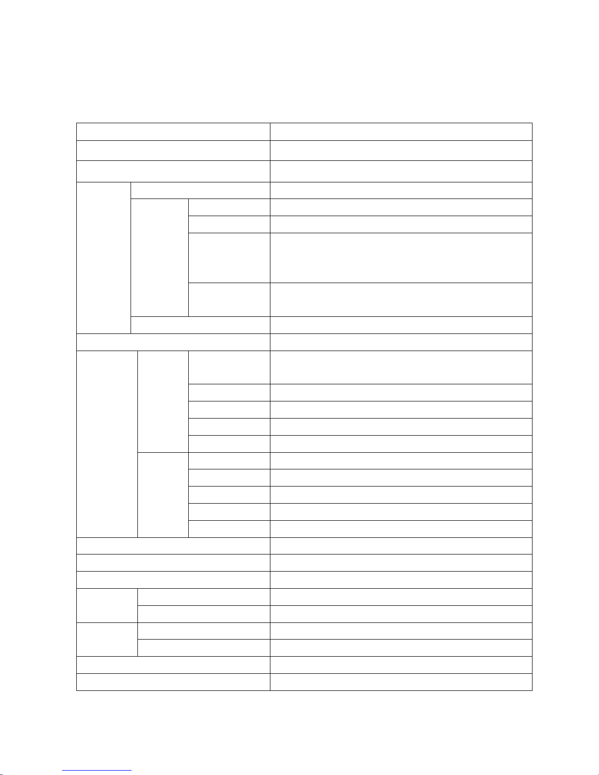
[1] SPECIFICATIONS
Item Model: LC-32SV40U
LCD screen size 32 inches diagonal
Resolution 1366 x 768
TV-standard American TV Standard ATSC/NTSC System
VHF/UHF VHF 2-13ch, UHF 14-69ch
CATV 1-125ch (non-scrambled channel only)
Digital Terrestrial
Broadcast
(8VSB)
2-69ch
Receiving
channel
Digital cable*1
(64/256 QAM)
1-135ch (non-scrambled channel only)
TV
function
Audio multiplex BTSC System
Audio out 5W*2
ANT./CABLE
75 Ω Unbalance ,F Type x 1 for Analog (VHF/UHF/CATV) and
Digital(AIR/CABLE)
INPUT2 HDMI in with HDCP
INPUT3 HDMI in with HDCP
Audio PC/HDMI Audio in (Ø 3.5mm jack)
Rear
PC IN Analog RGB (PC) in (15-pin mini D-sub female connector)
Headphone out Ø 3.5mm jack (Audio output)
SPDIF HDMI in with HDCP
RS-232C D-sub 9 pin for service & Hotel mode using
INPUT1 HDMI in with HDCP
Terminal
Side
USB Photo/Music/Video mode, Software update
OSD language English/French/Spanish
Power Requirement AC 120V ~60Hz
Power Consumption ≤100W (0.7 W Standby with AC 120 V)
TV + stand 10.4 kg
Weight
TV only 9.11 kg
TV + stand 787.26 mm x 561.12 mm x 247 mm Dimension
(W/H/D)
TV only 787.26 mm x 521.84 mm x 82 mm
Operating temperature +32°F to + 104°F (0°C to + 40°C)
Response time 8.5ms
5
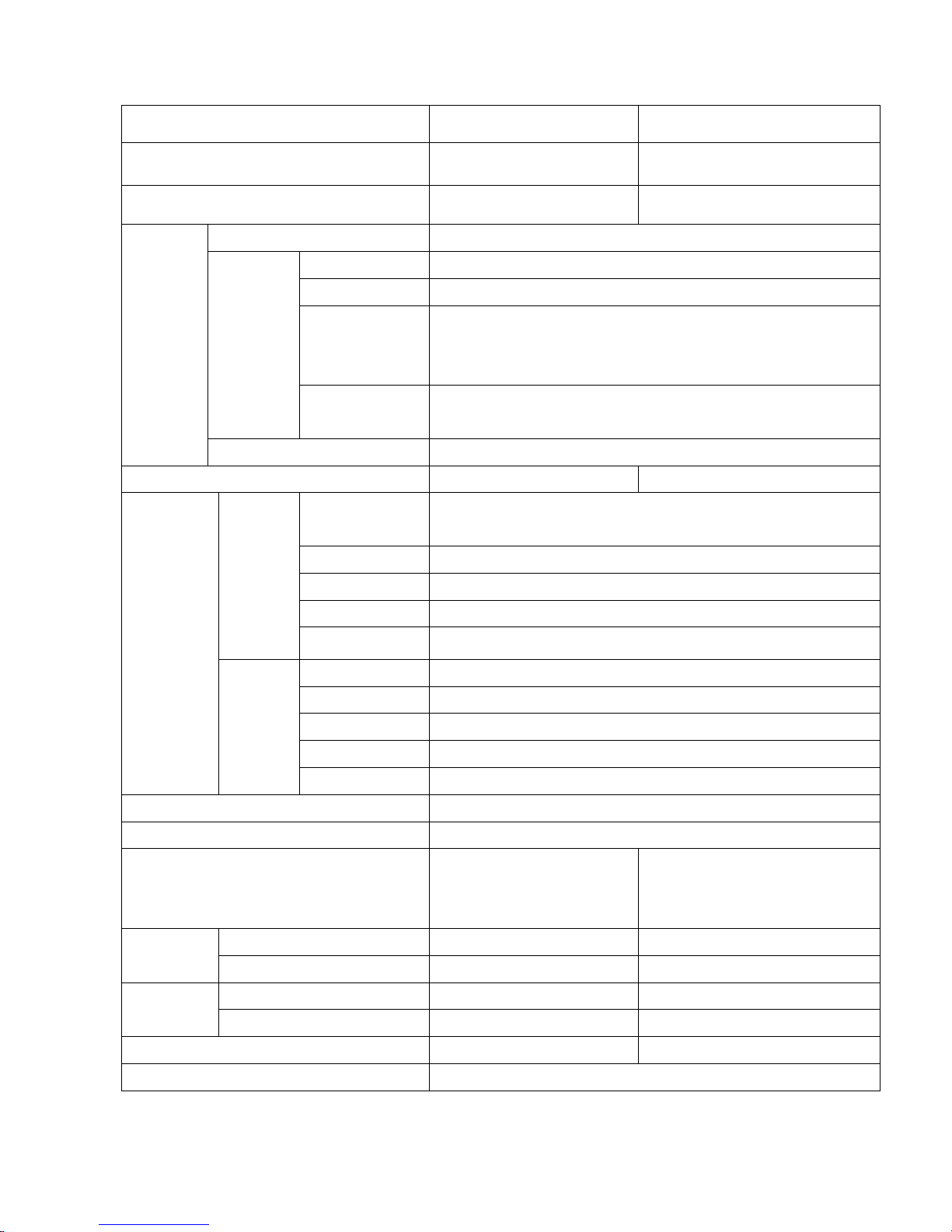
Item Model: LC-42SV50U Model: LC-46SV50U
LCD screen size 42 inches diagonal 46 inches diagonal
Resolution 1920 x 1080 1920 x 1080
TV-standard American TV Standard ATSC/NTSC System
VHF/UHF VHF 2-13ch, UHF 14-69ch
CATV 1-125ch (non-scrambled channel only)
Digital Terrestrial
Broadcast
(8VSB)
2-69ch
Receiving
channel
Digital cable*1
(64/256 QAM)
1-135ch (non-scrambled channel only)
TV
function
Audio multiplex BTSC System
Audio out 10W*2 10W*2
ANT./CABLE
75 Ω Unbalance ,F Type x 1 for Analog (VHF/UHF/CATV) and
Digital(AIR/CABLE)
INPUT2 HDMI in with HDCP
INPUT3 HDMI in with HDCP
Audio PC/HDMI Audio in (Ø 3.5mm jack)
Rear
PC IN Analog RGB (PC) in (15-pin mini D-sub female connector)
Headphone out Ø 3.5mm jack (Audio output)
SPDIF HDMI in with HDCP
RS-232C D-sub 9 pin for service & Hotel mode using
INPUT1 HDMI in with HDCP
Terminal
Side
USB Photo/Music/Video mode, Software update
OSD language English/French/Spanish
Power Requirement AC 120V ~60Hz
Power Consumption
170W
(0.7 W Standby with AC 120
V)
210W
(0.7 W Standby with AC 120 V)
TV + stand 17619g 25.5KG
Weight
TV only 15382g 22.8
TV + stand 1038.73*707.07*284.34MM 1119.55X753.11X315.00MM
Dimension
(W/H/D)
TV only 1038.73*688.77*89.5MM 1119.55X708.14X95.50MM
Response time 8ms 6.5ms
Operating temperature +32°F to + 104°F (0°C to + 40°C)
6
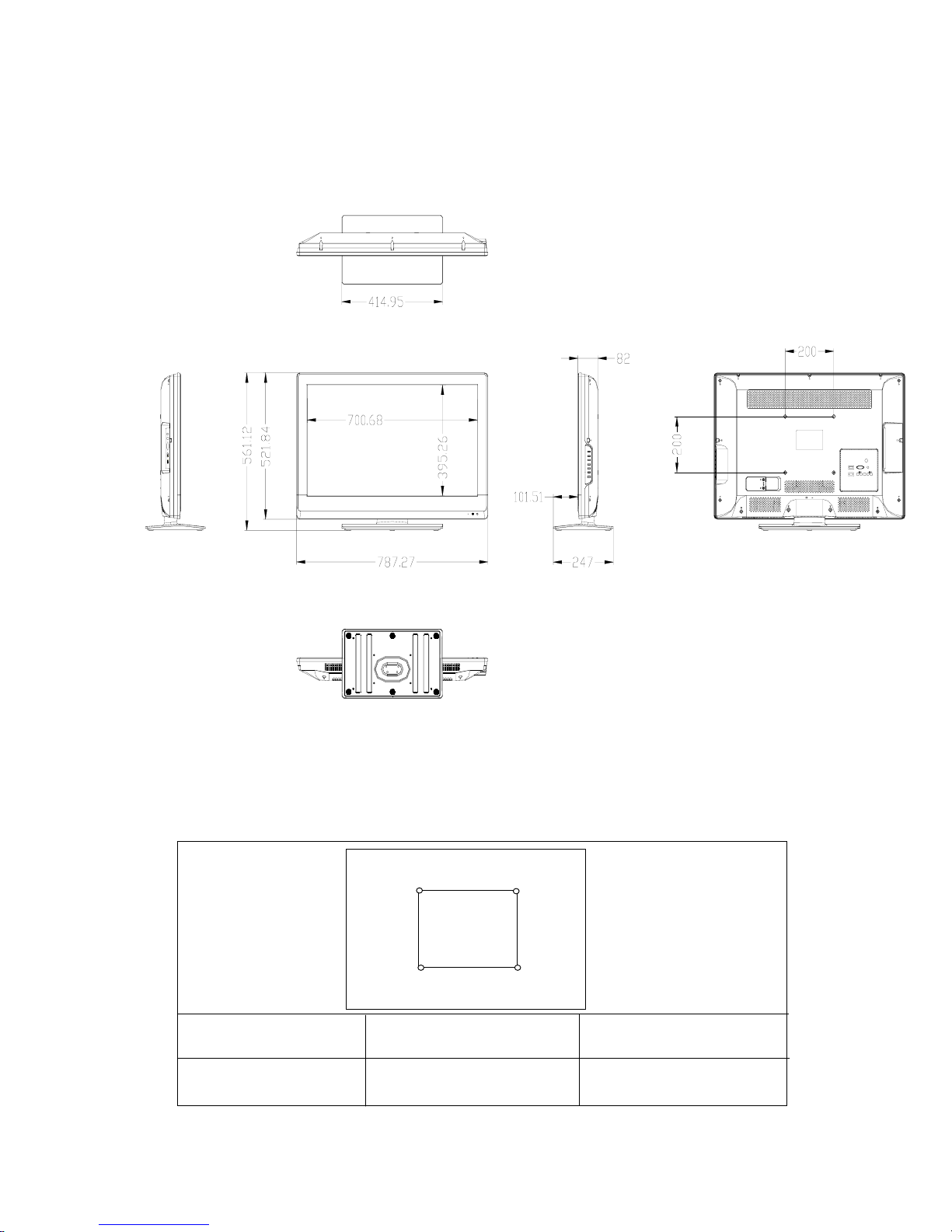
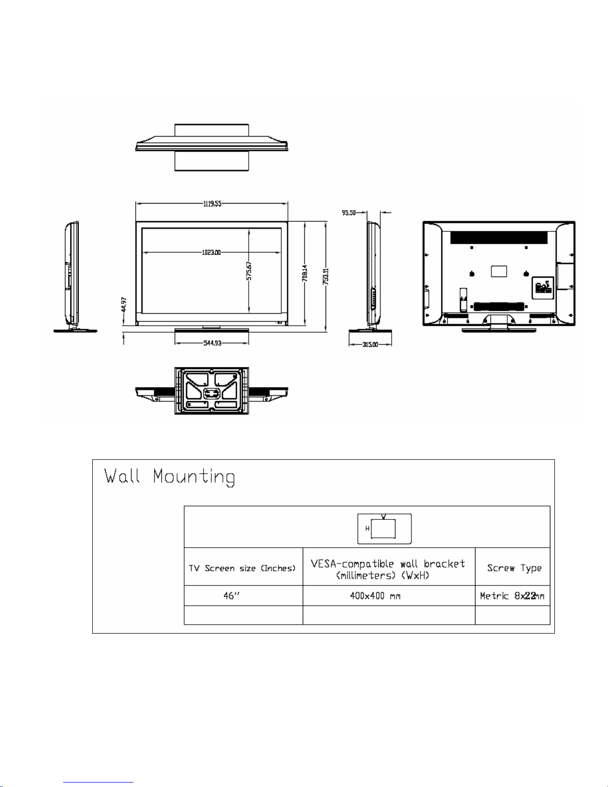
[2]DIMENSIONS
LC-32SV40U
32"(LC-32SV40U)
TV screen size (Inchs)
VESA compatible wall-bracket
(
millimeters) ( W x H
)
200X200mm
Screw type
Metric 6x12mm
Wall Mounting
W
H
7
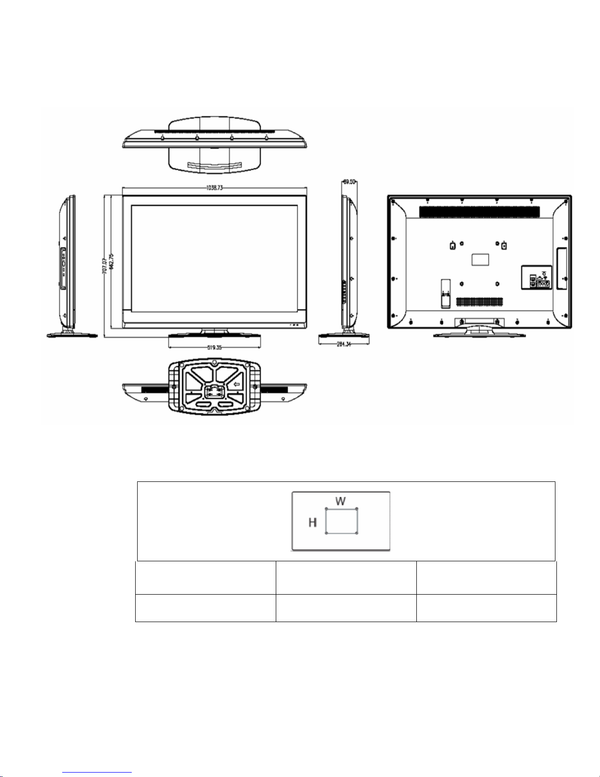
LC-42SV50U
wall mounting
TV screen size (Inches)
VESA-compatible wall bracket
(millimeters)(W*H)
Screw type
42'' 200*200mm Metric 8*22mm
8
LC-46SV50U
9
CHAPTER2. Removing of Major Parts
LC-32SV40U
1.Assy/PanelRemoval
Notes: Please put your machine on soft material to avoid to scrape panel when
you disassemble it.
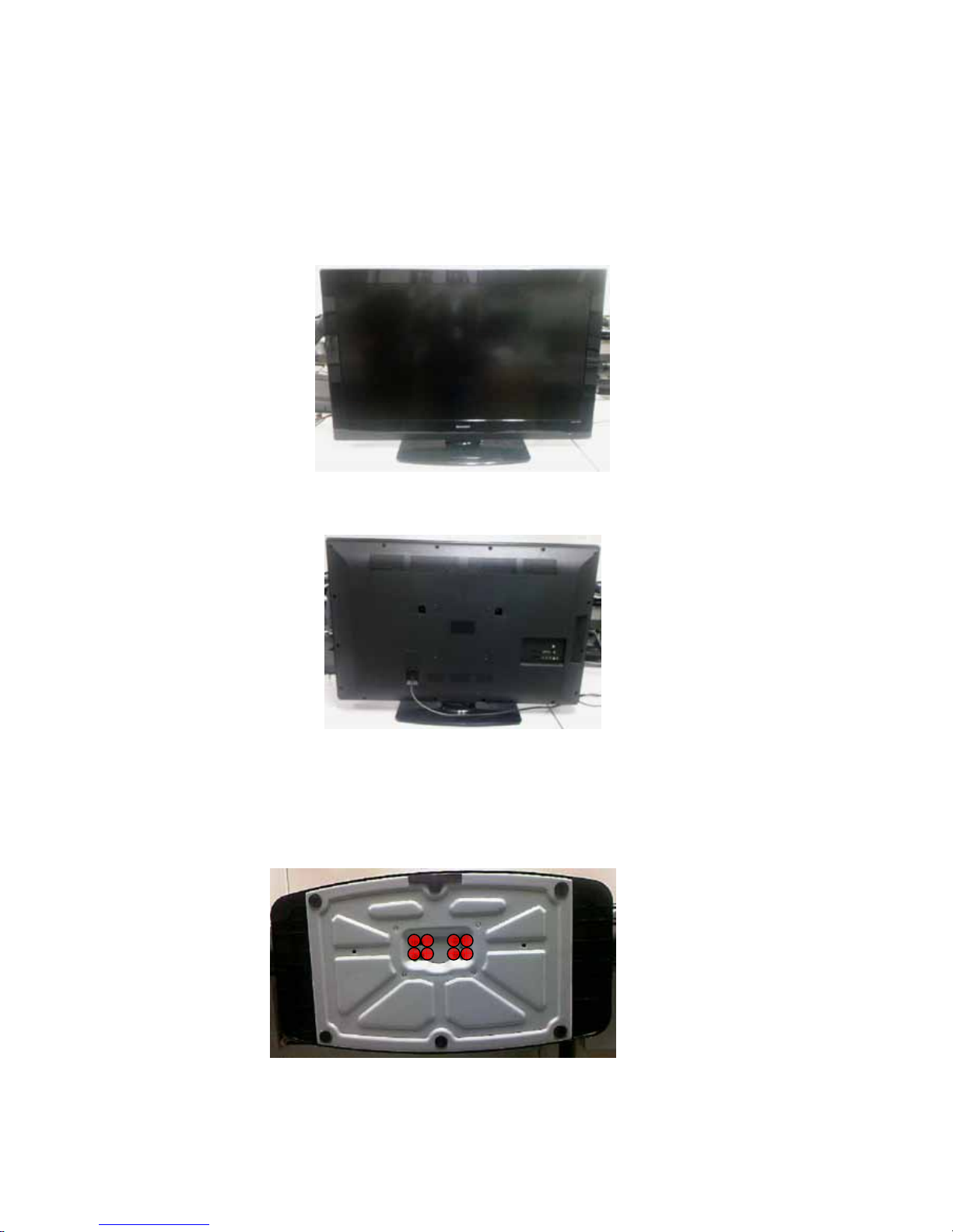
Front view
Fig.1
Back view
Fig.2
Step 1. Remove the Base Assy.
1. Remove the base as Fig.3.
Remove the 4 screws as Fig.3 and pull out the base.

10
Fig.3
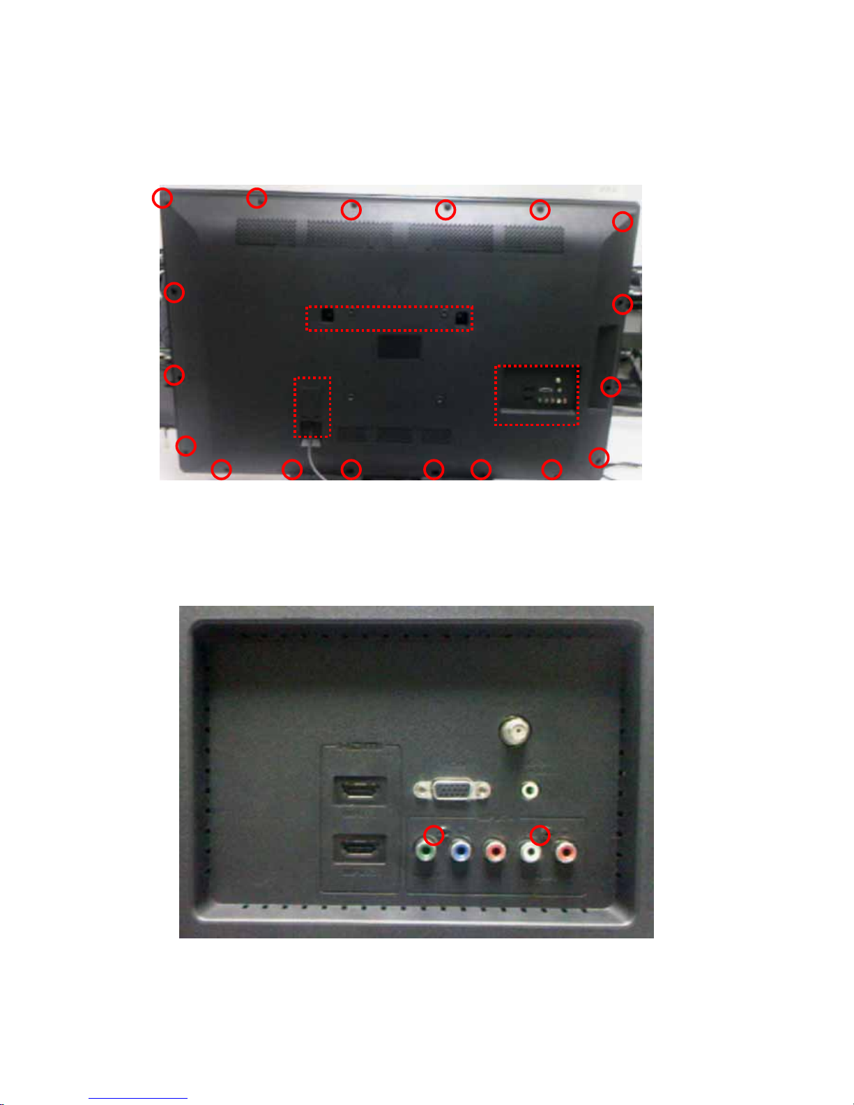
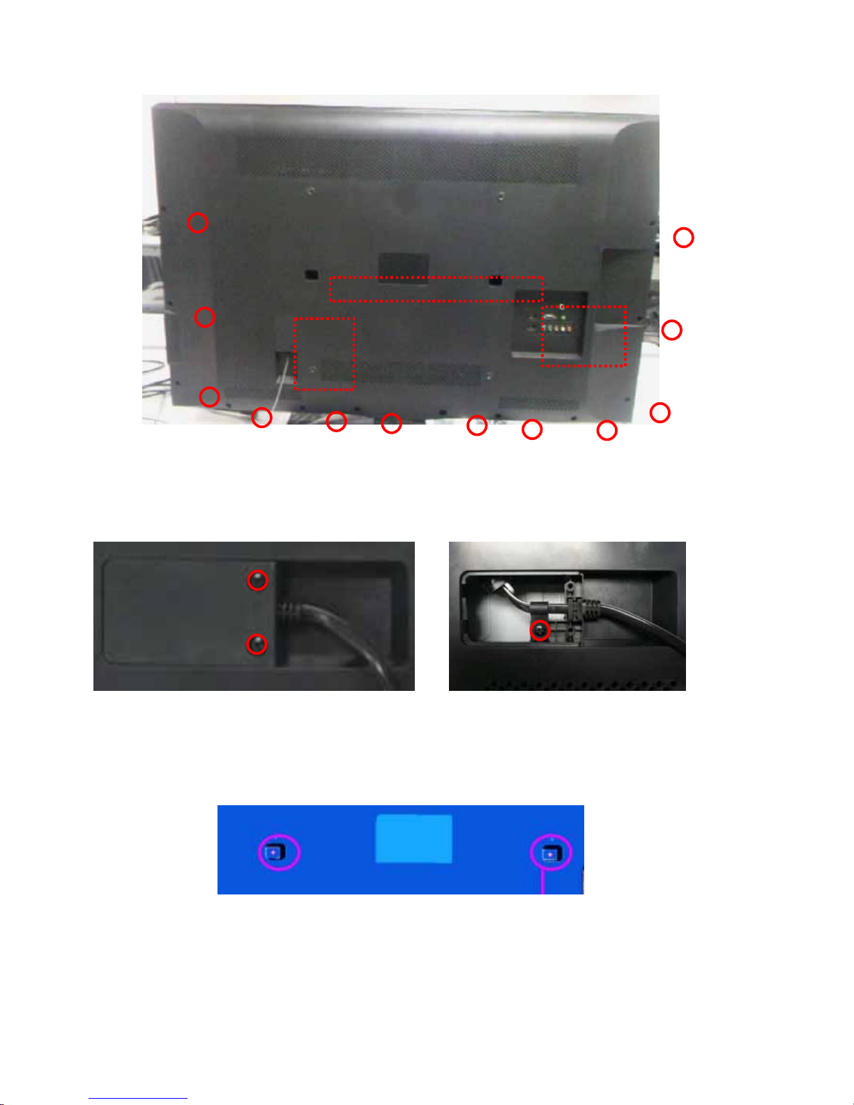
Step 2. Remove the REAR COVER Assy.
1. Remove the 13 screws,around the REAR COVER as Fig.4.
Fig.4
2. Remove the 2 screws at the IO area as Fig.5.
11
Fig.5
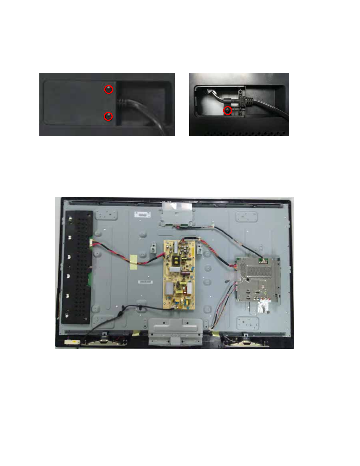
3. Remove the 3 screws to release AC cable as Fig.6 .Fig.7
Fig.6
Fig.7
Step 3. Remove the Main, Power ,IR board , Key Pad ASSY, and the Speakers.
12
Fig.8
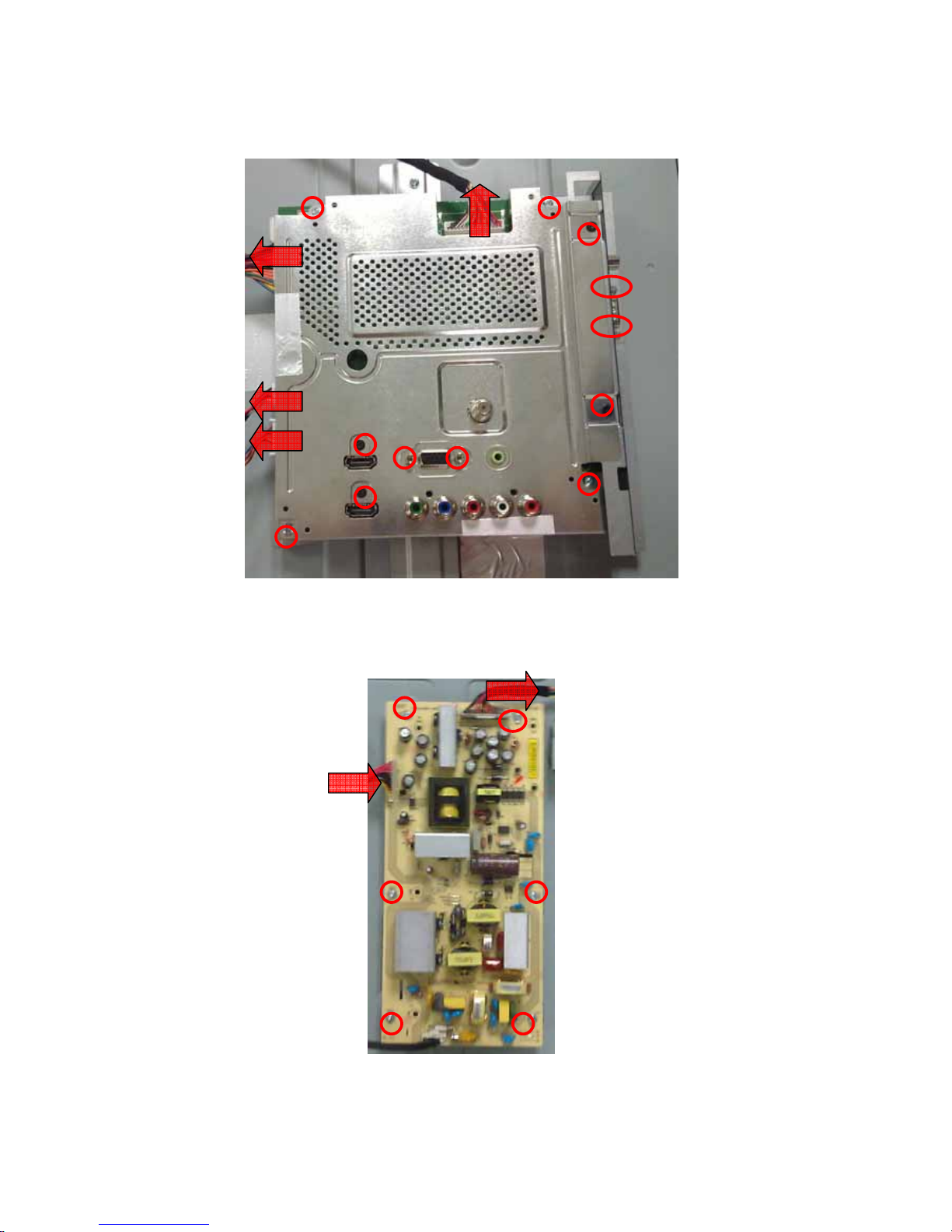
1. Remove the 4 screws and disconnect 4 cables .Detach the Main board ASSY
as Fig.9

13
Fig.9
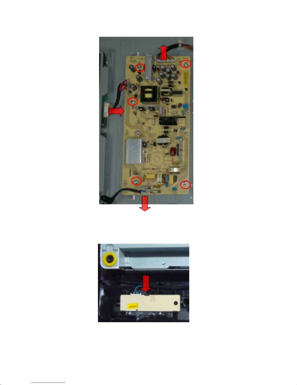
2. Remove the 5screws and 2 Cables. Detach the Power board as Fig.10.
14
Fig.10
3. .Detach the IR board as Fig.11.
Fig.11
15
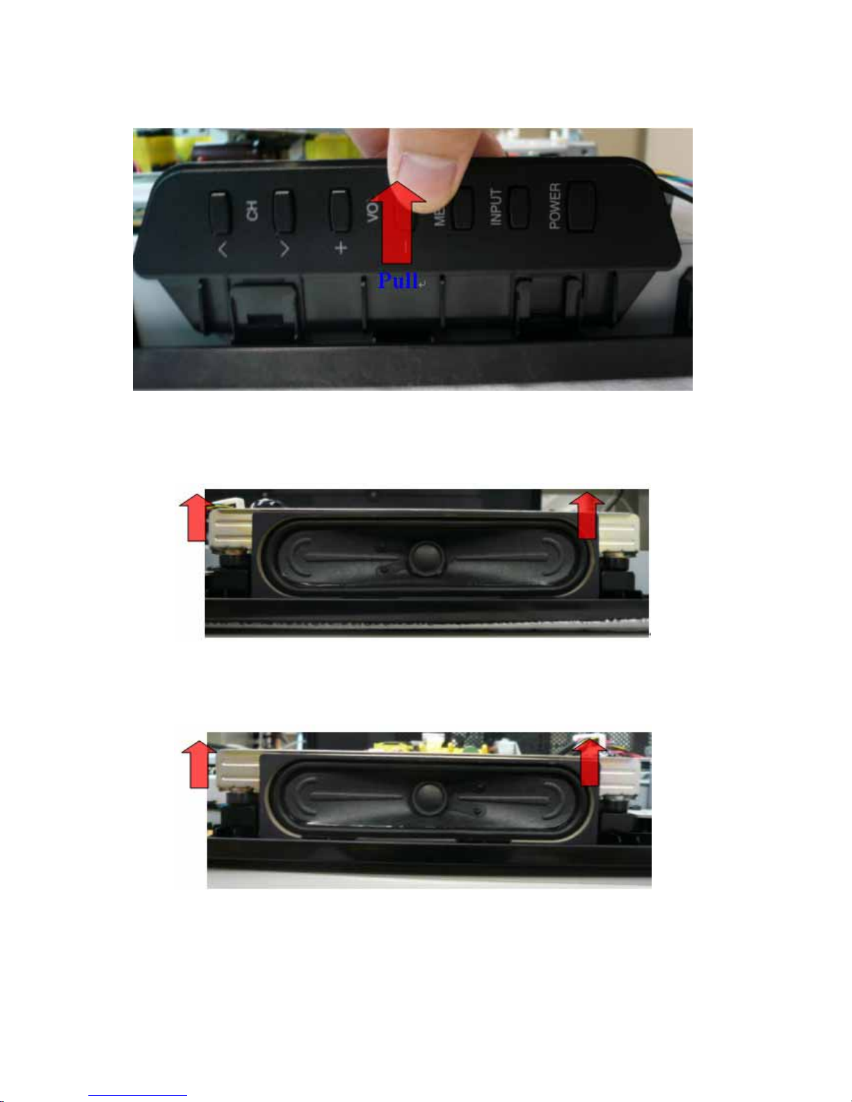
4. Detach the Key Pad ASSY as Fig.12.
Fig.12
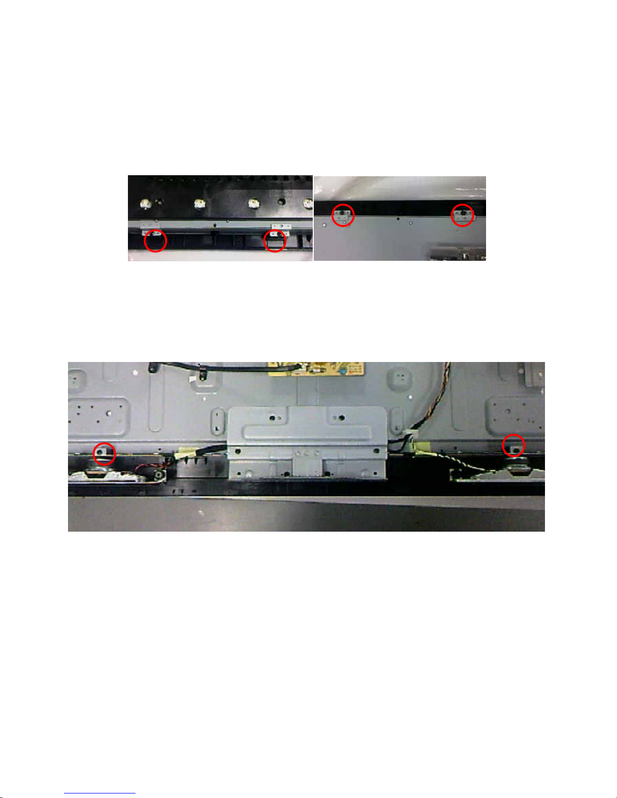
5. Detach the Speakers as Fig.13. Fig.14.
Fig.13
Fig.14
Pull

16
Step 4. Remove TOP VESA,VESA PLATE,AND BASE SUPPORT,.
1.Remove the 6 screws. Detach the TOP VESA and VESA PLATE as Fig.15
Fig.15
2.Remove the 4 screws. Detach the BASE SUPPORT as Fig.16
Fig.16
Step 5. Remove PANEL module.
Remove the 2 screws at the bottom side of panel as Fig.17.
Fig.17
17
LC-42SV50U
1. Assy/Panel Removal
Notes: Please put your machine on soft material to avoid to scrape panel when
you disassemble it.
Front view
Fig.1
Back view
Fig.2
Step 1. Remove the Base Assy.
2. Remove the base as Fig.3.
Remove the 8 screws as Fig.3 and pull out the base.
Fig.3
18
Step 2. Remove the REAR COVER Assy.
1. Remove the 18 screws,around the REAR COVER as Fig.4.
Fig.4
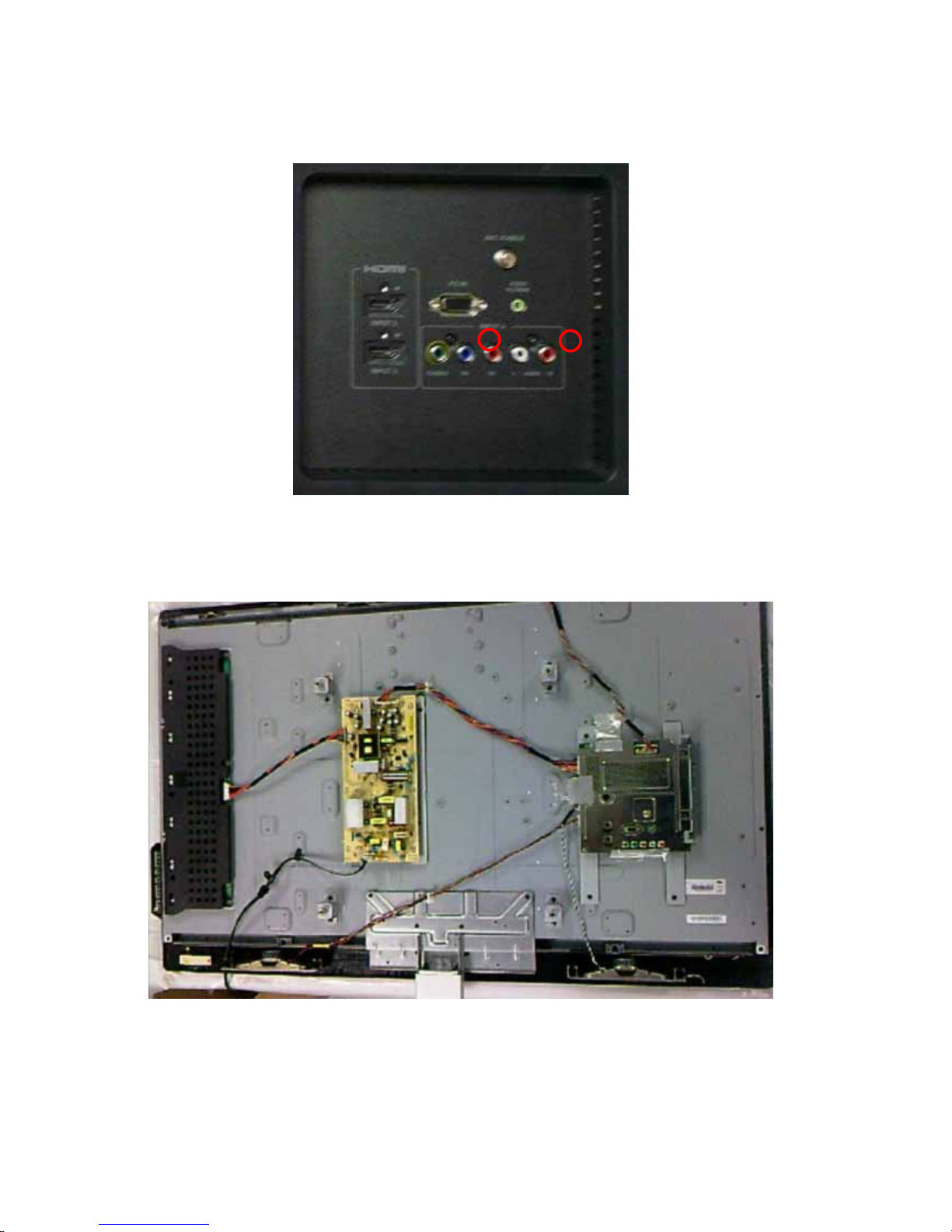
2. Remove the 2 screws at the IO area as Fig.5.
Fig.5
2
3
2
19
3. Remove the 3 screws to release AC cable as Fig.6 .Fig.7
Fig.6 Fig.7
Step 3. Remove the Main, Power ,IR board , Key Pad ASSY, and the Speakers.
Fig.8
20
1. Remove the 12 screws and disconnect 4 cables .Detach the Main board ASSY
as Fig.9
Fig.9
2. Remove the 6screws and 2 Cables. Detach the Power board as Fig.10.
Fig.10

21
3. Detach the IR board as Fig.11.
Fig.11
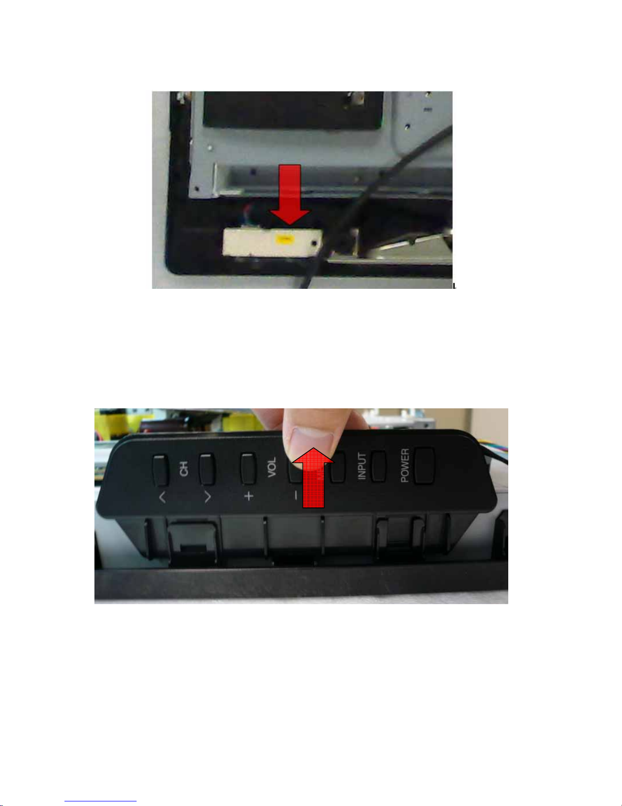
4. Remove the 2screws ,Detach the Key Pad ASSY as Fig.12.
Fig.12

22
5. Detach the Speakers as Fig.13. Fig.14.
Fig.13
Fig.14
Step 4. Remove BASE SUPPORT.
Remove the 6 screws. Detach the BASE SUPPORT as Fig.15
23
Fig.15
Step 5. Remove PANEL module.
1. Remove the 4 screws at the left and right side of panel as Fig.16, Fig.17
Fig.16 Fig.17
2. Remove the 2 screws at the bottom side of panel as Fig.18.
Fig.18

24
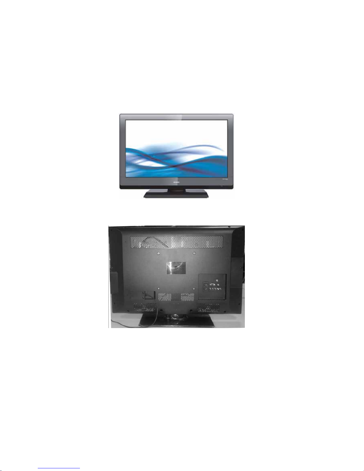
LC-46SV50U
1.Assy/PanelRemoval
Notes: Please put your machine on soft material to avoid to scrape panel when
you disassemble it.
Front view
Fig.1
Back view
Fig.2
Step 1. Remove the Base Assy.
3. Remove the base as Fig.3.
Remove the 4 screws as Fig.3-1 and pull out the base.

25
Fig.3-1
2. Remove stand support from stand cover and stand bracket after loose the four
screws
Fig.3-2
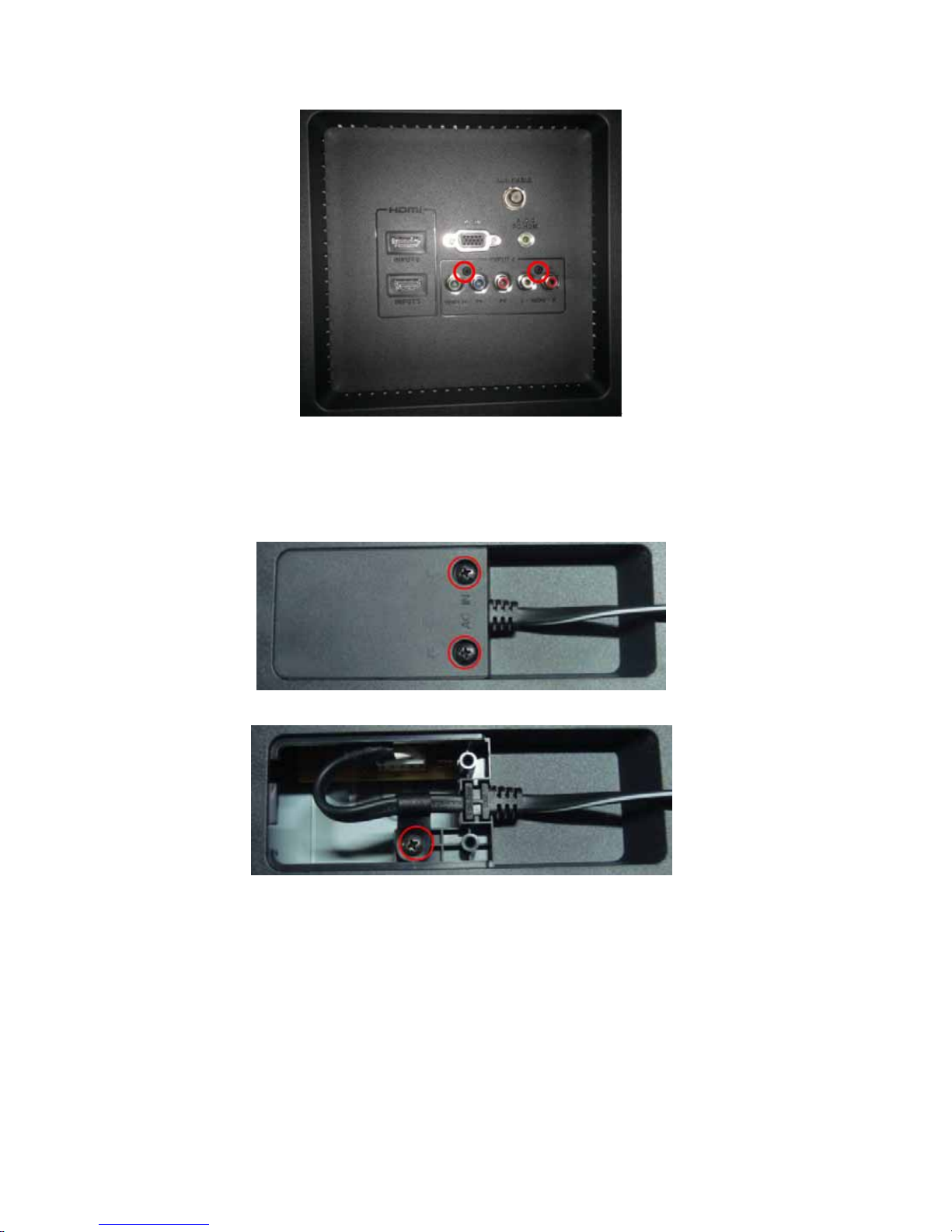
Step 2. Remove the REAR COVER Assy.
1. Remove the 12screws,around the REAR COVER as Fig.4.
26
Fig.4
2. Remove the 3 screws to release AC cable as Fig.5 .Fig.6
Fig.5 Fig.6
3. Remove the 2 screws to release REAR COVER VESA as Fig.7
Fig.7
4
2
3
27
4. Remove the 2 screws at the IO area as Fig.8.
Fig.8
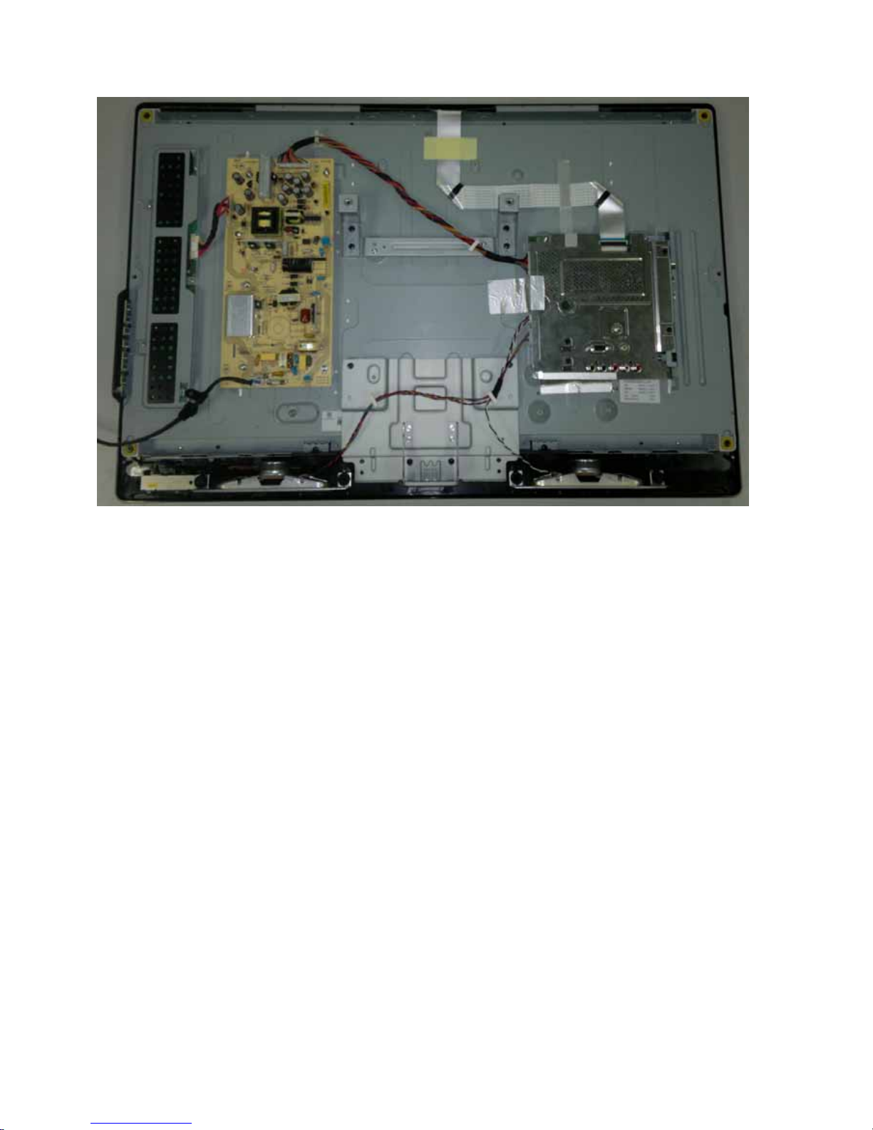
Step 3. Remove the Main, Power ,IR board , Key Pad ASSY, and the Speakers.
Fig.9
1. Remove the 12 screws and disconnect 4 cables .Detach the Main board ASSY
as Fig.10

28
Fig.10
2. Remove the 6screws and 2 Cables. Detach the Power board as Fig.11.
Fig.11
29
3. Detach the IR board as Fig.12.
Fig.12
3. Detach the Key Pad ASSY as Fig.13.
Fig.13
5. Detach the Speakers as Fig.14. Fig.15.
Pull
 Loading...