

Page 1

LC-19SH7E/RU, LC-26SH7E/RU, LC-32SH7E/RU, LC-42SH7E/RU
1
SERVICE MANUAL
No.
LCD COLOUR TELEVISION
LC-19SH7E/RU
LC-26SH7E/RU
LC-32SH7E/RU
MODELS LC-42SH7E/RU
In the interests of user-safety (Required by safety regulations in some countries) the set should be restored to its original condition and only parts identical to those specified should be used.
Parts marked with " " are important for maintaining the safety of the set. Be sure to replace these parts with specified ones for maintaining the
safety and performance of the set.
This document has been published to be used for
after sales service only.
The contents are subject to change without notice.
SAFETY PRECAUTION
IMPORTANT SERVICE SAFETY PRE-
CAUTION ....................................................................2
Precautions for using lead-free solder ......………........3
CHAPTER 1. OPERATION MANUAL
[1] SPECIFICATIONS ..................................................4
[2] OPERATION MANUAL ...........................................5
[3] DIMENSIONS .......................................................10
CHAPTER 2. REMOVING OF MAJOR PARTS
[1] REMOVING OF MAJOR PARTS ..........................11
CHAPTER 3. ADJUSTMENT PROCEDURE
[1] ADJUSTMENT PROCEDURE .............................31
[2] SERVICE MODE ..................................................42
[3]
SOFTWARE UPGRADE PROCEDURE...............43
CHAPTER 4. TROUBLESHOOTING TABLE
[1] TROUBLESHOOTING TABLE..............................45
CHAPTER 5. MAJOR IC INFORMATIONS
[1] MAJOR IC INFORMATIONS.................................98
CHAPTER 6. BLOCK DIAGRAM/WIRING DIAGRAM
[1] BLOCK DIAGRAM ..............................................118
CONTENTS
[2] POWER MANAGEMENT BLOCK DIAGRAM ......120
[3] WIRING DIAGRAM ...............................................122
CHAPTER 7. PRINTED WIRING BOARD
[1] MAIN UNIT PRINTED WIRING BOARD ...............126
[2] POWER UNIT PRINTED WIRING BOARD ..........130
[3] KEY UNIT PRINTED WIRING BOARD .................134
[4] IR UNIT PRINTED WIRING BOARD ....................136
CHAPTER 8. SCHEMATIC DIAGRAM
[1] MAIN SCHEMATIC DIAGRAM ............................138
[2] POWER SCHEMATIC DIAGRAM ........................166
[3] KEY SCHEMATIC DIAGRAM ..............................169
[4] IR SCHEMATIC DIAGRAM ..................................171
CHAPTER 9. Parts Guide
[1] SPARE PARTS LIST.............................................173
[2] CABINET PARTS ..................................................250
[3] SUPPLIED ACCESSOORIES................................258
[4] PACKING PARTS..................................................259
Page 2
LC-19SH7E/RU, LC-26SH7E/RU, LC-32SH7E/RU, LC-42SH7E/RU
2
SAFETY PRECAUTION
IMPORTANT SERVICE SAFETY PRECAUTION
■ Service work should be performed only by qualified service technicians who are thoroughly familiar with all safety checks and the
servicing guidelines which follow:
■ WARNING
1. For continued safety, no modification of any circuit should be
attempted.
2. Disconnect AC power before servicing.
CAUTION:
FOR CONTINUED PROTECTION AGAINST A
RISK OF FIRE REPLACE ONLY WITH SAME
TYPE FUSE.
42" F901 (T6.3AH/250V)
26"/32" F901 (T5AH/250V)
■
BEFORE RETURNING THE RECEIVER
(Fire & Shock Hazard)
Before returning the receiver to the user, perform the following
safety checks:
3. Inspect all lead dress to make certain that leads are not pinched,
and check that hardware is not lodged between the chassis and
other metal parts in the receiver.
4. Inspect all protective devices such as non-metallic control knobs,
insulation materials, cabinet backs, adjustment and compartment
covers or shields, isolation resistor-capacitor networks, mechanical
insulators, etc.
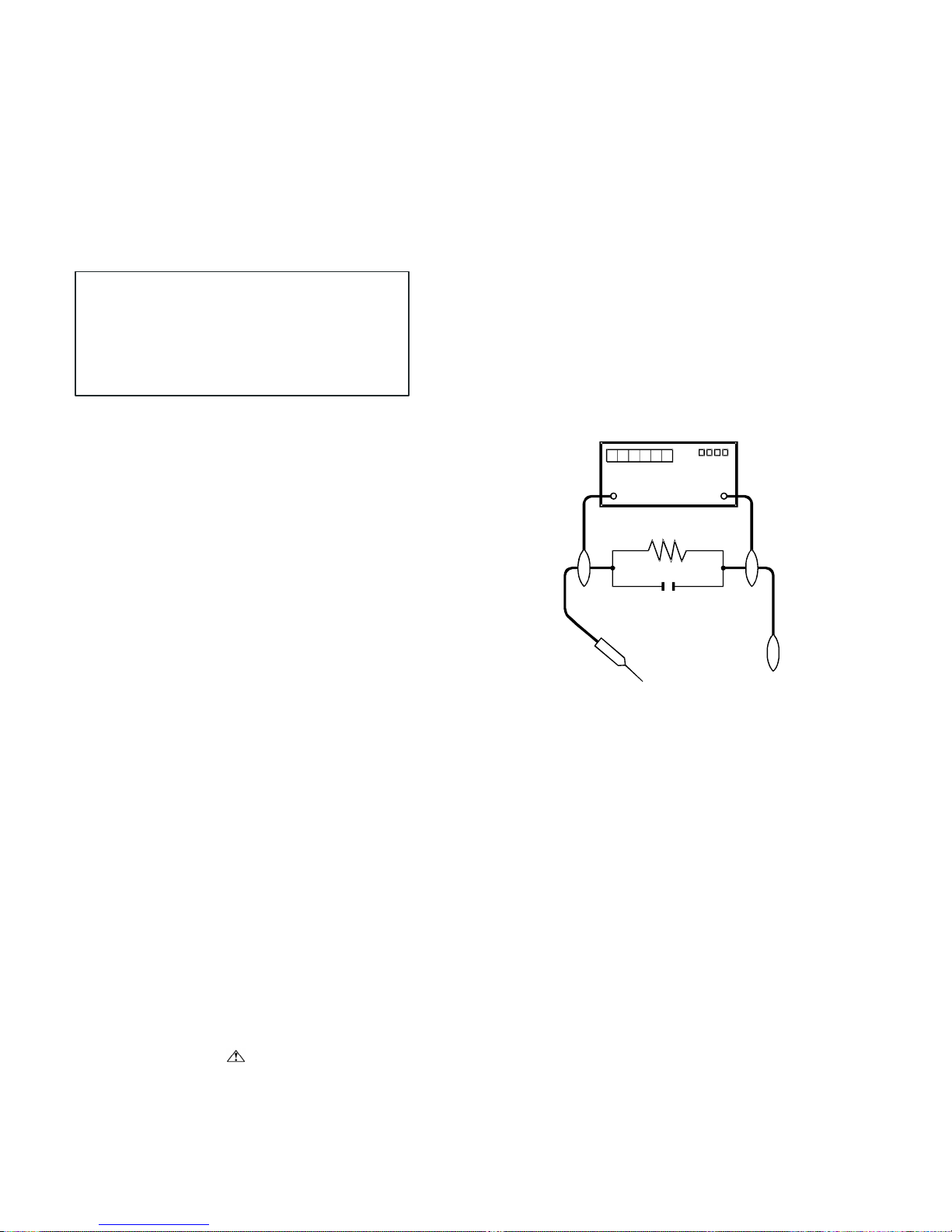
5. To be sure that no shock hazard exists, check for leakage current in
the following manner.
• Plug the AC cord directly into a 220~240 volt AC outlet.
• Using two clip leads, connect a 1.5k ohm, 10 watt resistor paralleled
by a 0.15µF capacitor in series with all exposed metal cabinet
parts and a known earth ground, such as electrical conduit or
electrical ground connected to an earth ground.
• Use an AC voltmeter having with 5000 ohm per volt, or higher, sen-
sitivity or measure the AC voltage drop across the resistor.
• Connect the resistor connection to all exposed metal parts having a
return to the chassis (antenna, metal cabinet, screw heads, knobs
and control shafts, escutcheon, etc.) and measure the AC voltage
drop across the resistor.
All checks must be repeated with the AC cord plug connection
reversed. (If necessary, a nonpolarized adaptor plug must be used
only for the purpose of completing these checks.)
Any reading of 1.05 V peak (this corresponds to 0.7 mA peak AC.)
or more is excessive and indicates a potential shock hazard which
must be corrected before returning the monitor to the owner.
DVM
AC SCALE
1.5k ohm
10W
0.15 µF
TEST PROBE
TO EXPOSED
METAL PARTS
//////////////////////////////////////////////////////////////////////////////////////////////////////////////////////////////////////////////////////////////////////////////////////////////////////////////////////////////////////////////////
SAFETY NOTICE
Many electrical and mechanical parts in LCD color television have
special safety-related characteristics.
These characteristics are often not evident from visual inspection,
nor
can protection afforded by them be necessarily increased by using
replacement components rated for higher voltage, wattage, etc.
Replacement parts which have these special safety characteristics
are identified in this manual; electrical components having such
features are identified by “ ” and shaded areas in the Replacement
Parts List and Schematic Diagrams.
For continued protection, replacement parts must be identical to those
used in the original circuit.
The use of a substitute replacement parts which do not have the same
safety characteristics as the factory recommended replacement parts
shown in this service manual, may create shock, fire or other hazards.
//////////////////////////////////////////////////////////////////////////////////////////////////////////////////////////////////////////////////////////////////////////////////////////////////////////////////////////////////////////////////
CONNECT TO KNOWN
EARTH GROUND
Page 3

LC-19SH7E/RU, LC-26SH7E/RU, LC-32SH7E/RU, LC-42SH7E/RU
3
Precautions for using lead-free solder
Using lead-free wire solder
• When fixing the PWB soldered with the lead-free solder, apply lead-free wire solder. Repairing with conventional lead wire solder may cause
damage or accident due to cracks.
As the melting point of lead-free solder (Sn-Ag-Cu) is higher than the lead wire solder by 40 °C, we recommend you to use a dedicated soldering
bit, if you are not familiar with how to obtain lead-free wire solder or soldering bit, contact our service station or service branch in your area.
Soldering
• As the melting point of lead-free solder (Sn-Ag-Cu) is about 220 °C which is higher than the conventional lead solder by 40 °C, and as it has
poor solder wettability, you may be apt to keep the soldering bit in contact with the PWB for extended period of time. However, Since the land
may be peeled off or the maximum heat-resistance temperature of parts may be exceeded, remove the bit from the PWB as soon as you
confirm the steady soldering condition.
Lead-free solder contains more tin, and the end of the soldering bit may be easily corroded. Make sure to turn on and off the power of the bit as
required.
If a different type of solder stays on the tip of the soldering bit, it is alloyed with lead-free solder. Clean the bit after every use of it.
When the tip of the soldering bit is blackened during use, file it with steel wool or fine sandpaper.
• Be careful when replacing parts with polarity indication on the PWB silk.
Page 4
LC-32SH25E
4
CHAPTER 1. OPERATION MANUAL
[1] SPECIFICATIONS
Specification
Item
19” lCD Colour TV,
model: lC-19SH7E
26” lCD Colour TV,
model: lC-26SH7E
32” lCD Colour TV,
model: lC-32SH7E
42” LCD COLOUR TV,
Model: LC-42SH7E
LCD screen size 19” diagonal 26” diagonal 32” diagonal 42” diagonal
Number of dots
3,147,264 dots
(1366 x 768 x 3 dots)
6,220,800 dots
(1920 x 1080 x 3 dots)
Video Colour System
PAL/SECAM/NTSC 3.58/NTSC 4.43/PAL 60
Analogue
CCIR (B/G, I, D/K, L/L’)
TVStandard
Digital
DVB-T (2K/8K OFDM)
VHF/UHF ATV : IRA-E69, DVB-T : E5-E69
Receiving
Channel
CATV S-band, S1–S41ch
TV-Tuning System Auto Preset 999 ch, Auto Label, Auto Sort
TV
Function
STEREO/BILINGUAL NICAM/A2
Backlight life
50,000 hours (at Backlight
Standard position)
50,000 hours (at Backlight
Standard position)
60,000 hours (at Backlight Standard position)
Viewing angles H : 170° V : 160° H : 160° V : 150° H : 176° V : 176°
Audio amplifier 3W X 2 5W X 2 5W X 2 10W X 2
Speaker (128.8 mm x 40.2 mm) x 2 (164.5 mm x 42 mm) x 2 (164.5 mm x 42 mm) x 2 (166 mm x 55mm) x 2
Antenna
UHF/VHF 75 Ω
RS-232C 3 pin connector(For service only)
SCART 1 SCART (AV input, Y/C input, RGB input, TV output)
SCART 2
(Only for 26” and 32”)
SCART (AV input, Y/C input, monitor output [analogue source - ATV, SCART 1, SIDE AV; digital source - DTV])
PC IN D-sub 15 pin (AV input), Ø 3.5mm jack (Audio output)
Component YPbPr, RCA pin (L/R)
SPDIF Digital audio output
AUDIO OUT
(Only for 26” and 32”)
RCA pin (L/R)
AVOUT(Only for 19”) RCA pin (AV output)
HDMI 1
Rear
HDMI 2(Only for 26”
and 32”)
C. I. (Common
Interface)
EN50221, R206001
Headphones Ø 3.5mm jack (Audio output)
AV IN
RCA pin (AV input).
S-VIDEO ([Y/C input], Not available for 19”)
Side
HDMI 3(only for 32”)
OSD language
English, German, French, Italian, Dutch, Spanish, Greek, Portuguese, Swedish, Finnish,
Russian, Polish, Turkish, Hungarian, Czech, Slovak, Danish, Norwegian, Estonian, Latvian,
Lithuanian, Slovenian, Bulgarian, Croatian, Romanian, Serbian, Ukrainian, Gaelic.
Power Requirement
AC 220–240 V, 50 Hz
Power Consumption
45W (Standby<0.3W)
(Method IEC60107)
55W (Standby<0.3W)
(Method IEC60107)
135W (Standby<0.3W)
(Method IEC60107)
170 W (Standby < 0.3W)
(Method IEC60107)
Weight
3.8 kg (Without stand),
4.0 kg (With stand)
7.3 kg (Without stand),
8.4 kg (With stand)
11.0 kg (Without stand),
12.4 kg (With stand)
16.5kg (Without stand),
19.1 kg (With stand)
Operating temperature 0°C to + 40°C
• As a part of policy of continuous improvement, SHARP reserves the right to make design and specification changes for product improvement
without prior notice. The performance specification figures indicated are nominal values of production units. There may be some deviations
from these values in individual units.
Page 5

2008-03-14
LC-19SH7E/RU, LC-26SH7E/RU, LC-32SH7E/RU, LC-42SH7E/RU
5
[2] OPERATION MANUAL
Remote control unit
(POWER)
Press to turn the LCD TV on or enter standby mode.
(SOURCE)
Select an input source.
0-9 DIGIT BUTTONS
To select a TV channel directly.
EPG
Press this button to display electronic program guide
in DTV mode.
PRE CH
To display the previous selected TV channel.
HDMI
Press this button you could select HDMI (19”) /
HDMI 1(26”, 32”) / HDMI 2 (26”, 32”) / HDMI 3 (32”).
YPbPr
Press this button you could select YPbPr.
VIDEO
Press this button you could select AV / SCART 1
/SCART 2 (26”, 32”)
PC
Press to direct to the PC mode.
(+/-)
Press to adjust the volume.
Press to toggle audio on and off. You can also press
Vol (+/-) to restore the previous volume level.
(Picture format)
Select picture format to Auto / Normal / Zoom 1/ Zoom
2 / Wide.
P (</>)
Press to select the channel.
DUAL
Select MONO, STEREO, DUAL 1 and DUAL 2 for
ATV channel. Select Audio language for DTV channel.
AUDIO (ADJ)
Press to set the LCD TV to a predefined sound setting.
Personal / Music / Speech
VIDEO (ADJ)
Press to set the LCD TV to a predefined picture
setting. Personal / Standard / Vivid / Movie / Eco
SLEEP
Press to turn the LCD TV off within an amount of time.
(10 ~ 120 minutes.)
∧∨<>
Press ∧∨<> to navigate and confirm your selection.
OK
Press to activate a setting.
MENU / EXIT
Press to activate the LCD TV OSD. Press again to exit
the LCD TV OSD.
Display programme infomation, if available.
TELETEXT
Press this button to activate Teletext. Press again to
turn off Teletext.
MIX
Press this button to activate Teletext with TV.
SIZE
Press this button to change the font size: Full screen,
Top half and Bottom half.
SUBPAGE
To select the subpage when the current page contains
subpage(s).
INDEX
Press this button to return to page 100 or the index
page; and then press 0 to 9. The teletext page will be
numbered and added to the page you select or the
secondary item.
SUBTITLE
For DTV, press it to select subtitle setting.
Off / On / On during mute
For ATV, please activate Teletext to select subtitle
page.
HOLD
Press this button to stop the scrolling of pages.
The text decoder stops receiving data.
REVEAL
Reveal hidden information such as answers to a quiz.
ECO
Press buttons to set the picture with less brightness for
saving energy.
PR LIST
Press to display a list of channels. Then press Red
button to select the Digital or Analogue channel list.
FREEZE
Set the still image. Press again to return to normal
screen.
R/G/Y/B (COLOUR BUTTON)
Press buttons to select the pictures with various
colours of text. Different channels display different
functions.
When you are viewing the channel list, press R button
can go to the previous page, and press G can go to
the next page.
Page 6

LC-19SH7E/RU, LC-26SH7E/RU, LC-32SH7E/RU, LC-42SH7E/RU
6
TV (Front view)
TV (Rear view)
Page 7
2008-03-14
LC-19SH7E/RU, LC-26SH7E/RU, LC-32SH7E/RU, LC-42SH7E/RU
7
Preparation
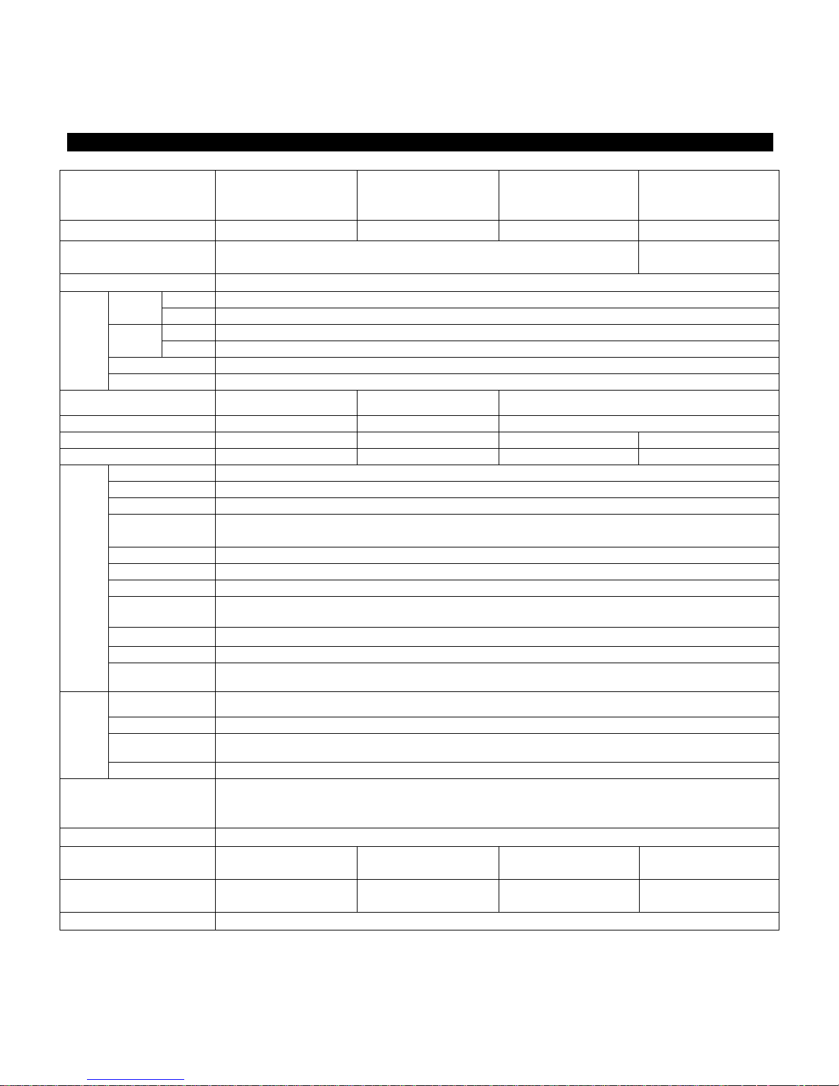
Mount the TV Stand
1. Put the TV face down on a safe surface
that is covered by a soft and smooth cloth.
2. Adjust the TV stand to the bottom of the TV.
3. Fasten the screws by using a cross-head screwdriver. (Not supplied).
NOTE:
To detach the TV stand, perform the steps in reverse order.
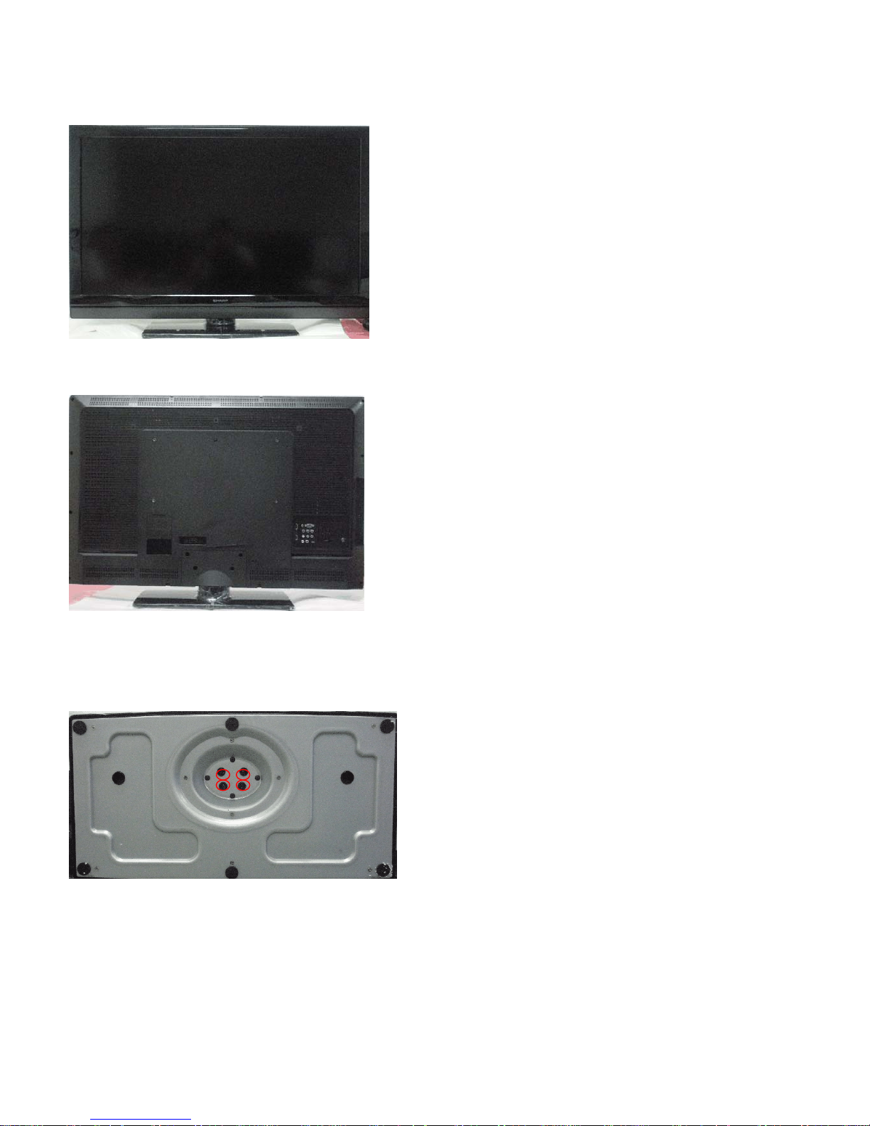
Wall mounting
TV screen size
( inches)
VESA-compatible wall bracket
(millimeters) (W x H)
Screw type
19” 100 x 100 mm Metric 4 x 10 mm
26” 200 x 100 mm Metric 4 x 10 mm
32” 200 x 200 mm Metric 6 x 10 mm
42” 400 x 200 mm Metric 6 x 10 mm
.
Page 8
LC-19SH7E/RU, LC-26SH7E/RU, LC-32SH7E/RU, LC-42SH7E/RU
8
preparation
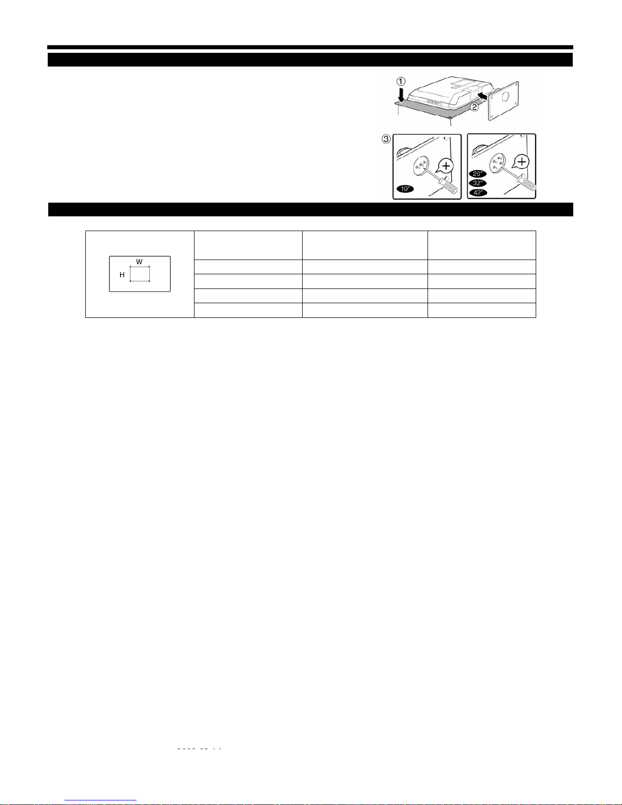
Installation of batteries
1. insert two AAA batteries into Remote control.
Make sure (+) and (-) are facing the proper
direction.
2. Replace the cover.
NOTE
• If the remote control will not to be used for a long
time, remove the batteries to avoid remote control damage.
CAUTION
Improper use of batteries can result in chemical leakage or explosion. Be sure to follow the instructions below.
• Do not mix batteries of different types. Different types of batteries have different characteristics.
• Do not mix old and new batteries. Mixing old and new batteries can shorten the life of new batteries or cause
chemical leakage in old batteries.
• Remove batteries as soon as they have worn out. Chemicals that leak from batteries can cause a rash. If you find
any chemical leakage, wipe thoroughly with a cloth.
• The batteries supplied with this product may have a shorter life expectancy due to storage conditions.
• If you will not be using the remote control unit for an extended period of time, remove the batteries from it.
Note on disposing batteries:
The batteries provided contain no harmful materials such as cadmium, lead or mercury.
Regulations concerning used batteries stipulate that batteries may no longer be thrown out with the household
Rubbish. Deposit any used batteries free of charge into the designated collection containers set up at commercial
Businesses.
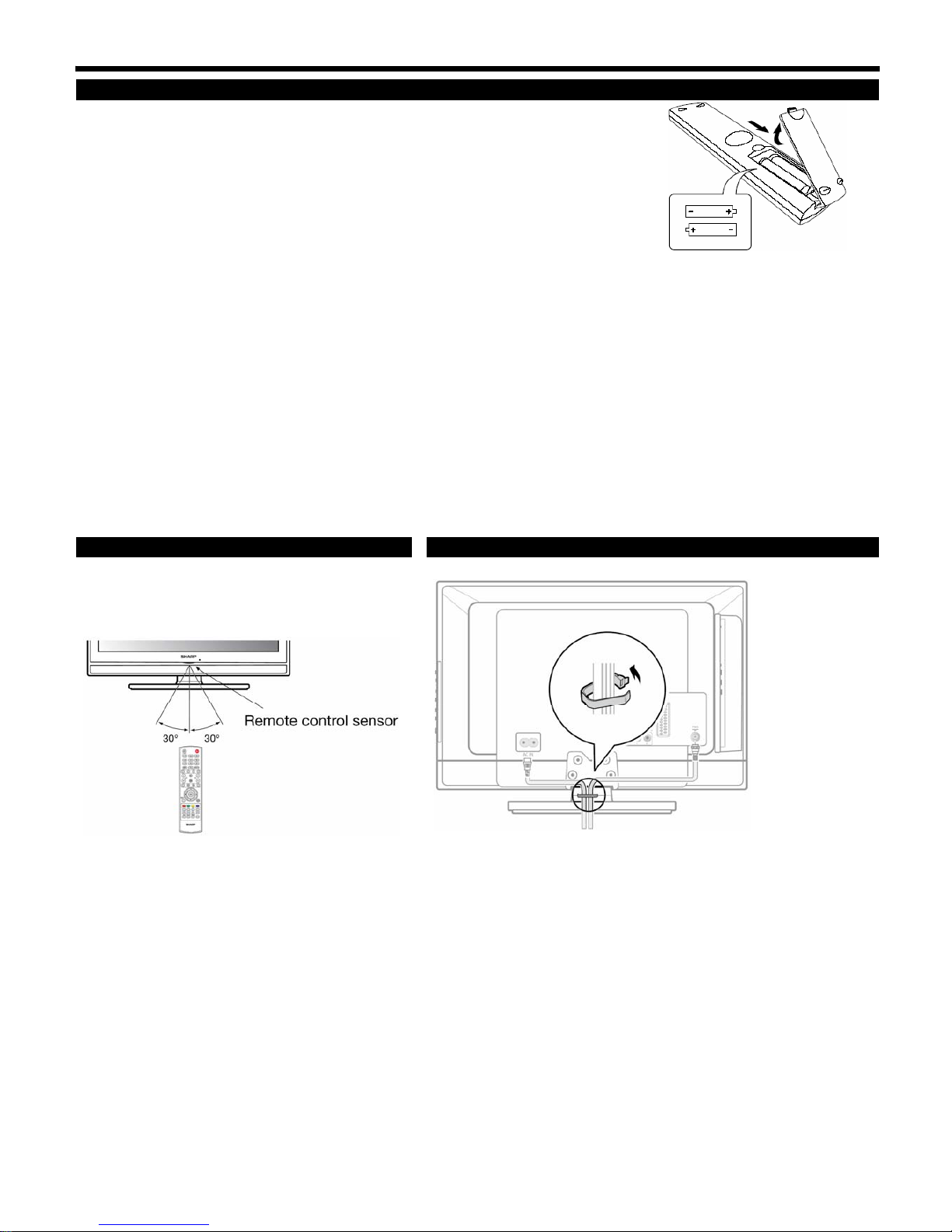
Using the remote control unit Bundling the cables
Use the remote control unit by pointing it towards the
remote control sensor. Objects between the remote
control unit and sensor may prevent proper operation.
Page 9

2008-03-14
LC-19SH7E/RU, LC-26SH7E/RU, LC-32SH7E/RU, LC-42SH7E/RU
9
Appendix
troubleshooting
problem possible Solution
No picture 1. Connect power cord correctly.
2. Turn on power.
3. Connect signal cable correctly.
4. Press any button on the LCD TV.
Abnormal colours Connect signal cable correctly.
Twisted picture 1. Connect signal cable correctly.
2. Please use compatible signal.
Picture too dark Adjust brightness and contrast.
Audio only, no images 1. Please check if input signal is connected correctly.
2. TV-RF signal must not be lower than 50dB.
Picture only, no audio 1. Connect signal cable correctly.
2. Adjust volume to proper level.
3. Connect audio signal cable correctly.
4. TV-RF signal must not be lower than 50dB.
Cannot use remote control 1. Please change battery.
2. Turn off power for 10 seconds; and then restart power.
Cannot receive sufficient channels
through antenna
Please use the Channel scan function to increase the number of channels not included in memory.
No colours Please adjust the colour setup
Blinking picture accompanied by ghost
image
1. Check the connection of antenna/signal cable.
2. Check if channel is in play mode.
3. Press signal source and change input mode.
Broken lines or segments
Adjust antenna.
Keep the TV away from noise sources, such as automobiles, neon lights, and hair dryers.
Certain TV channels are blocked (Hope to
acquire some channels)
Please use the Update scan method to add the channels not included in memory
Overlapping images or ghost images Please use multi-directional outdoor antenna. (If your TV is subject to the influence of nearby mountains or
buildings).
Cannot use a function If the item you choose turns gray, that item cannot be selected.
Cannot receive programs Please use the Update scan method to add the channels not included in memory.
1. When a lamp in LCD panel is broken and the
protector circuit in inverter operates and we
tune on the this set, LED keep red? or Green?
2. Service man only change the lamp in LCD
panel?
1. If the lamp(s) is(are) broken, panel inverter will not kick on the lamps, so TV set phenomena will be "no picture
on display."
But the TV system is still working, that is the RC can also control LED.
When AC power on, the LED will keep last status and when use RC DC power on, the LED will keep green light.
2. The failed panel should be sent back to Panel maker (CMO) via RMA process.
Panel maker (CMO) will not rework the lamps at customer's side since the repaired panel should be checked
through regular inspection flow to secure the quality.
Cautions regarding use in high and low temperature environments
• When the unit is used in a low temperature space (e.g. room, office), the picture may leave trails or appear slightly delayed. This
is not a malfunction, and the unit will recover when the temperature returns to normal.
• Do not leave the unit in a hot or cold location. Also, do not leave the unit in a location exposed to direct sunlight or near a
heater, as this may cause the cabinet to deform and the LCD panel to malfunction.
• Storage temperature: +5°C to +35°C.
information on the software license for this product
Software composition
The software included in this product is comprised of various software components whose individual copyrights are held by SHARP or by third parties.
Software developed by SHarp and open source software
The copyrights for the software components and various relevant documents included with this product that were developed or written by SHARP are
owned by SHARP and are protected by the Copyright Act, international treaties, and other relevant laws. This product also makes use of freely
distributed software and software components whose copyrights are held by third parties. These include software components covered by a GNU
General Public License (hereafter GPL), a GNU Lesser General Public License (hereafter LGPL) or other license Agreement.
obtaining source code
Some of the open source software licensors require the distributor to provide the source code with the executable software components. GPL and
LGPL include similar requirements. For information on obtaining the source code for the open source software and for obtaining the GPL, LGPL, and
other license agreement information, visit the following website:
http://www.sharp-eu.com/gpl/
We are unable to answer any questions about the source code for the open source software. The source code for the software components whose
copyrights are held by SHARP is not distributed.
acknowledgements
The following open source software components are included in this product:
•linuxkernel•modutils•glibc•zlib•libpng
Page 10

LC-19SH7E/RU, LC-26SH7E/RU, LC-32SH7E/RU, LC-42SH7E/RU
10
[3] DIMENSIONS
Page 11

2008-03-14
LC-19SH7E/RU, LC-26SH7E/RU, LC-32SH7E/RU, LC-42SH7E/RU
11
CHAPTER 2. REMOVING OF MAJOR PARTS
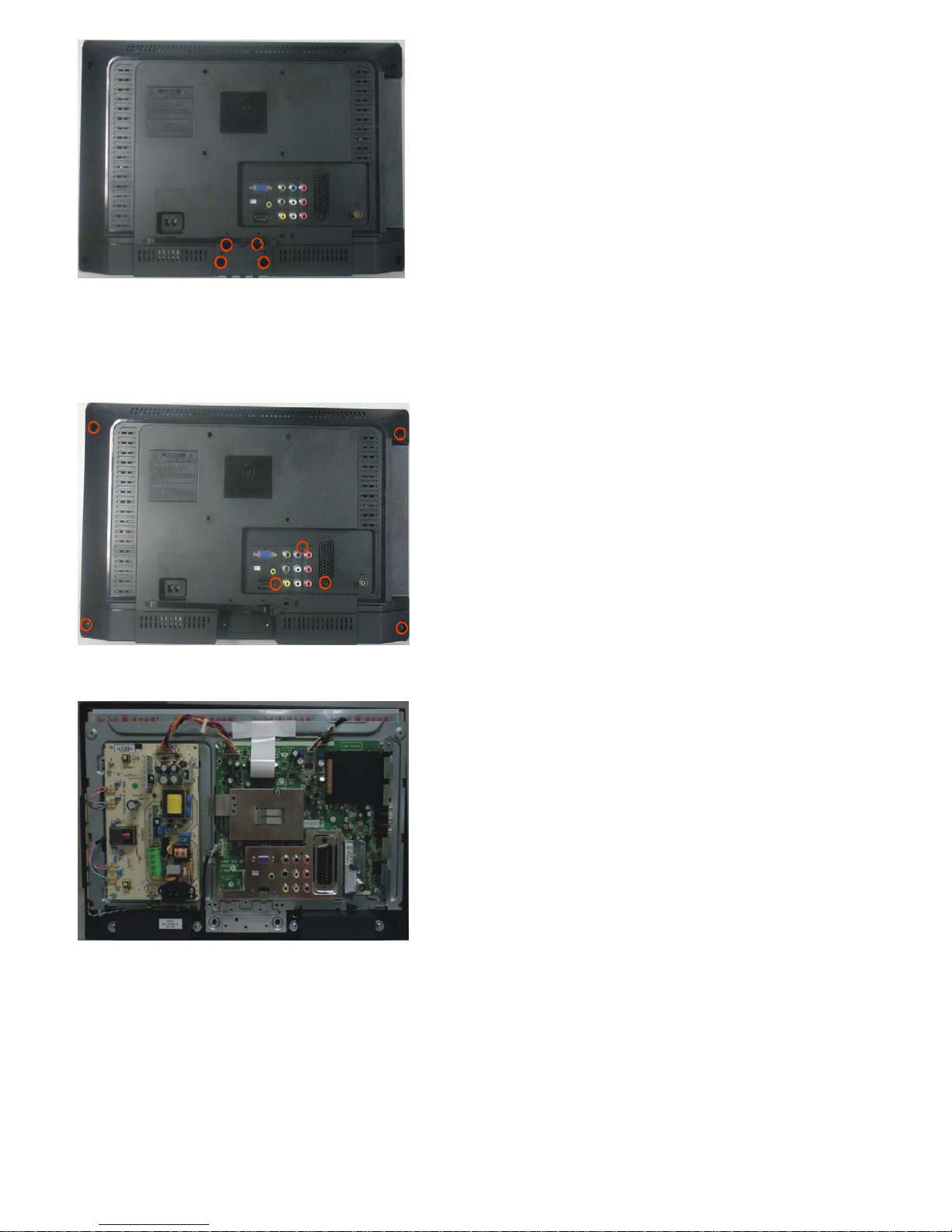
[1] REMOVING OF MAJOR PARTS(LC-19SH7E)
1. Assy/Panel Removal
Notes: Please put your machine on soft material to avoid to scrape panel when you disassemble it.
Front view
Fig.1
Back view
Fig.2
Step 1. Remove the Base Assy.
1. Remove the base as Fig.3.
Remove the 3 screws as Fig.3 and pull out the base as Fig.4
Fig.3
Page 12
LC-19SH7E/RU, LC-26SH7E/RU, LC-32SH7E/RU, LC-42SH7E/RU
12
Fig.4
2. Remove the 4 screws. Detach the Neck as Fig.5.
Step 2. Remove the REAR COVER Assy.
1. Remove the 7 screws. Detach the REAR COVER as Fig.5.
Fig.5
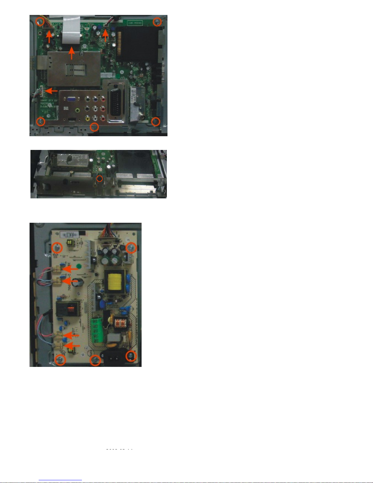
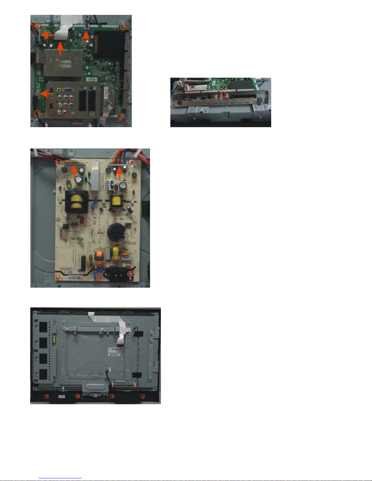
Step 3. Remove the Main and Power board.
Fig.6
1. Remove the 6 screws and disconnect 4 cables. Detach the Main board as Fig.7 and Fig.8.
Page 13
2008-03-14
LC-19SH7E/RU, LC-26SH7E/RU, LC-32SH7E/RU, LC-42SH7E/RU
13
Fig.7
Fig.8
2. Remove the 5 screws and disconnect 4 cables. Detach the Power board as Fig.9.
Fig.9
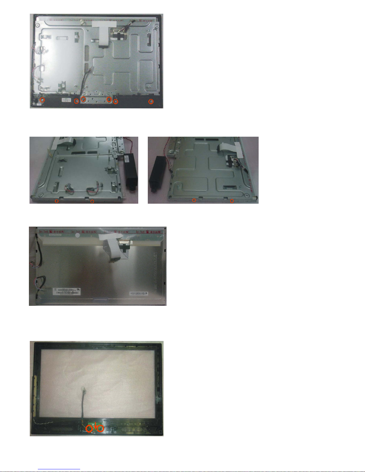
Step 4. Remove the Bezel.
1. Remove the 6 screws. Detach the Bezel as Fig.10.
Page 14
LC-19SH7E/RU, LC-26SH7E/RU, LC-32SH7E/RU, LC-42SH7E/RU
14
Fig.10
Step 5. Remove the Speakers and Metal Frame.
1. Remove the 4 screws. Detach the Metal Frame and Speakers as Fig.11 and Fig.12.
Fig.11 Fig.12
Panel:
Fig.13
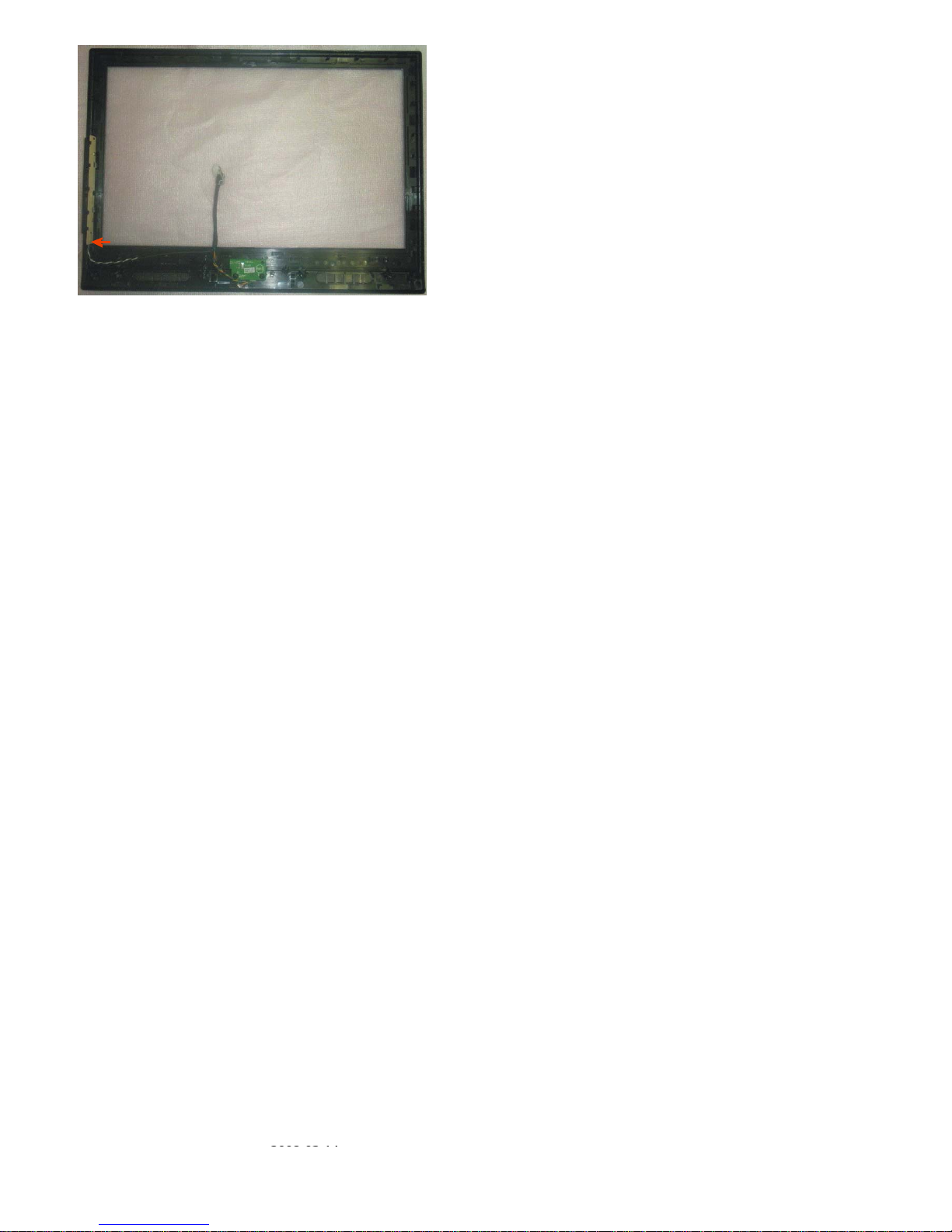
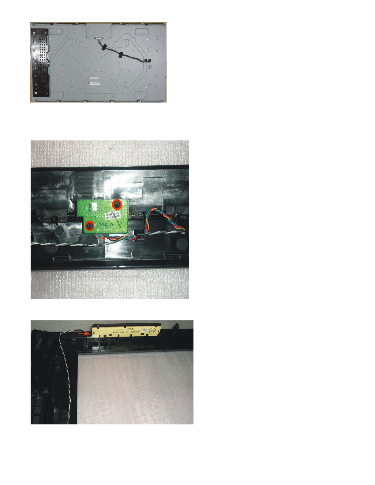
Step 6. Remove the IR and Key board.
1. Remove the 2 screws and disconnect 1 cable. Detach the IR board as Fig.14.
Fig.14
2. Disconnect 1 cable. Detach the Key board as Fig.15.
Page 15
2008-03-14
LC-19SH7E/RU, LC-26SH7E/RU, LC-32SH7E/RU, LC-42SH7E/RU
15
Fig.15
Page 16

LC-19SH7E/RU, LC-26SH7E/RU, LC-32SH7E/RU, LC-42SH7E/RU
16
REMOVING OF MAJOR PARTS(LC-26SH7E)
1. Assy/Panel Removal
Notes: Please put your machine on soft material to avoid to scrape panel when you disassemble it.
Front view
Fig.16
Back view
Fig.17
Step 1. Remove the Base Assy.
1. Remove the base as Fig.18.
Remove the 4 screws as Fig.18 and pull out the base as Fig.19
Fig.18
Page 17

2008-03-14
LC-19SH7E/RU, LC-26SH7E/RU, LC-32SH7E/RU, LC-42SH7E/RU
17
Fig.19
2. Remove the 4 screws. Detach the Neck as Fig.19.
Step 2. Remove the REAR COVER Assy.
1. Remove the 12 screws. Detach the REAR COVER as Fig.20.
Fig.20
Step 3. Remove the Main, Power board and the Speakers.
Fig.21
1. Remove the 5 screws and disconnect 4 cables. Detach the Main board as Fig.22 and Fig.23.
Page 18
LC-19SH7E/RU, LC-26SH7E/RU, LC-32SH7E/RU, LC-42SH7E/RU
18
Fig.22 Fig.23
2. Remove the 5 screws and disconnect 2 cables. Detach the Power board as Fig.24.
Fig.24
3. Remove the 4 screws. Detach the Speakers as Fig.25.
Fig.25
Step 4. Remove the Bracket and Bezel.
1. Remove the 8 screws. Detach the Bracket as Fig.26 and Fig.27.
Page 19

2008-03-14
LC-19SH7E/RU, LC-26SH7E/RU, LC-32SH7E/RU, LC-42SH7E/RU
19
Fig.26 Fig.27
2. Remove the 4 screws. Detach the Bezel as Fig.28.
Fig.28
Panel:
Fig.29
Step 5. Remove the IR and Key board.
1. Remove the 2 screws and disconnect 1 cable. Detach the IR board as Fig.30.
Page 20

LC-19SH7E/RU, LC-26SH7E/RU, LC-32SH7E/RU, LC-42SH7E/RU
20
Fig.30
2. Disconnect 1 cable. Detach the Key board as Fig.31.
Fig.31
2. Set Re-assembly
To re-assemble the whole set, execute all processes in reverse order.
Notes:
a. While re-assembling, make sure that all cables are placed and connected in their original position.
b. Pay special attention not to damage the EMC foams at the SSB shielding. Check that EMC foams are put
correctly on their places.
Page 21

2008-03-14
LC-19SH7E/RU, LC-26SH7E/RU, LC-32SH7E/RU, LC-42SH7E/RU
21
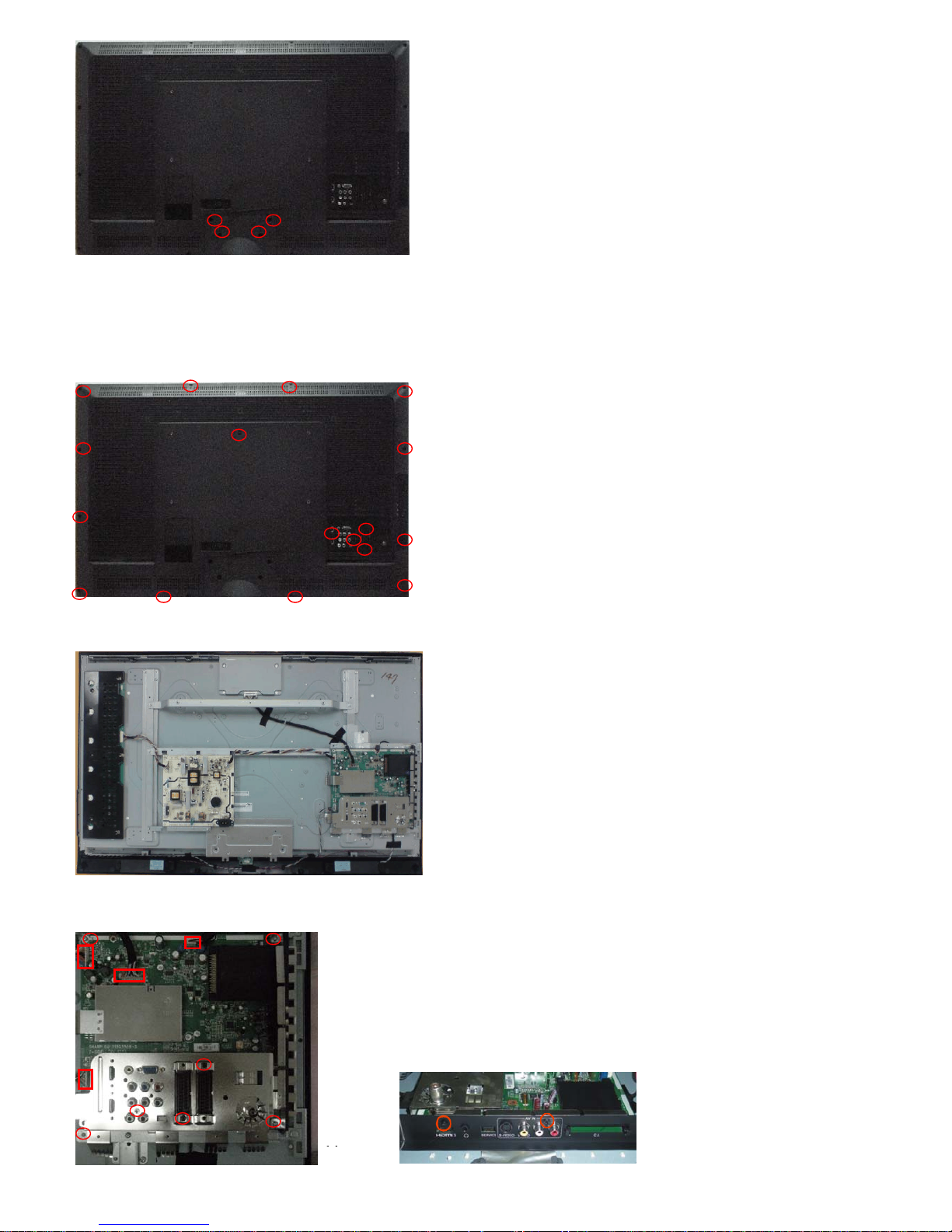
REMOVING OF MAJOR PARTS(LC-32SH7E)
1. Assy/Panel Removal
Notes: Please put your machine on soft material to avoid to scrape panel when you disassemble it.
Front view
Fig.32
Back view
Fig.33
Step 1. Remove the Base Assy.
1. Remove the base as Fig.34.
Remove the 4 screws as Fig.34 and pull out the base as Fig.35
Fig.34
Page 22

LC-19SH7E/RU, LC-26SH7E/RU, LC-32SH7E/RU, LC-42SH7E/RU
22
Fig.35
2. Remove the 4 screws. Detach the Neck as Fig.35.
Step 2. Remove the REAR COVER Assy.
1. Remove the 13 screws. Detach the REAR COVER as Fig.36.
Fig.36
Step 3. Remove the Main, Power board and the Speakers.
Fig.37
1. Remove the 6 screws and disconnect 3 cables. Detach the Main board as Fig.38 and Fig.39.
Page 23

2008-03-14
LC-19SH7E/RU, LC-26SH7E/RU, LC-32SH7E/RU, LC-42SH7E/RU
23
Fig.38 Fig.39
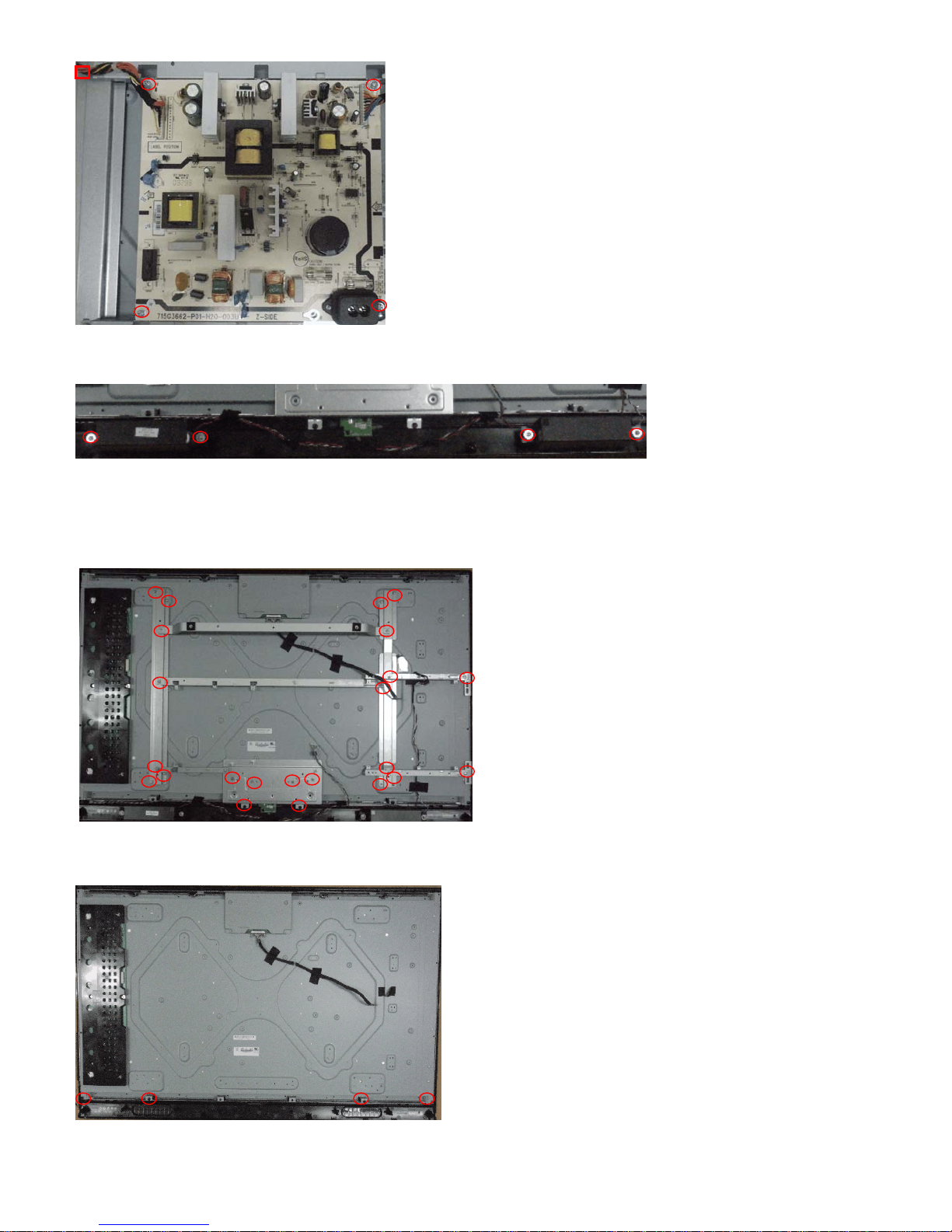
2. Remove the 4 screws and disconnect 1 cables. Detach the Power board as Fig.40.
Fig.40
3. Remove the 4 screws. Detach the Speakers as Fig.41.
Fig.41
Step 4. Remove the Bracket and Bezel.
1. Remove the 11 screws. Detach the Bracket as Fig.42 and Fig.43.
Fig.42 Fig.43
Page 24

LC-19SH7E/RU, LC-26SH7E/RU, LC-32SH7E/RU, LC-42SH7E/RU
24
2. Remove the 4 screws. Detach the Bezel as Fig.44.
Panel:
Fig.44
Step 5. Remove the IR and Key board.
1. Remove the 2 screws and disconnect 1 cable. Detach the IR board as Fig.45.
Fig.45
2. Disconnect 1 cable. Detach the Key board as Fig.46.
Fig.46
2. Set Re-assembly
To re-assemble the whole set, execute all processes in reverse order.
Notes:
Page 25

2008-03-14
LC-19SH7E/RU, LC-26SH7E/RU, LC-32SH7E/RU, LC-42SH7E/RU
25
a. While re-assembling, make sure that all cables are placed and connected in their original position.
b. Pay special attention not to damage the EMC foams at the SSB shielding. Check that EMC foams are put
correctly on their places.
Page 26
LC-19SH7E/RU, LC-26SH7E/RU, LC-32SH7E/RU, LC-42SH7E/RU
26
REMOVING OF MAJOR PARTS(LC-42SH7E)
1. Assy/Panel Removal
Notes: Please put your machine on soft material to avoid to scrape panel when you disassemble it.
Front view
Fig.47
Back view
Fig.48
Step 1. Remove the Base Assy.
1. Remove the base as Fig.49.
Remove the 4 screws as Fig.49 and pull out the base as Fig.50
Fig.49
Page 27
2008-03-14
LC-19SH7E/RU, LC-26SH7E/RU, LC-32SH7E/RU, LC-42SH7E/RU
27
Fig.50
2. Remove the 4 screws. Detach the Neck as Fig.50.
Step 2. Remove the REAR COVER Assy.
1. Remove the 17 screws. Detach the REAR COVER as Fig.51.
Fig.51
Step 3. Remove the Main, Power board and the Speakers.
Fig.52
1. Remove the 9 screws and disconnect 4 cables. Detach the Main board as Fig.53 and Fig.54.
Fig.53 Fig.54
Page 28
LC-19SH7E/RU, LC-26SH7E/RU, LC-32SH7E/RU, LC-42SH7E/RU
28
2. Remove the 4 screws and disconnect 1 cables. Detach the Power board as Fig.55.
Fig.55
3. Remove the 4 screws. Detach the Speakers as Fig.56.
Fig.56
Step 4. Remove the Bracket and Bezel.
1. Remove the 23 screws. Detach the Bracket as Fig.57.
Fig.57
2. Remove the 4 screws. Detach the Bezel as Fig.58.
Fig.58
Page 29
2008-03-14
LC-19SH7E/RU, LC-26SH7E/RU, LC-32SH7E/RU, LC-42SH7E/RU
29
Panel:
Fig.59
Step 5. Remove the IR and Key board.
1. Remove the 2 screws and disconnect 1 cable. Detach the IR board as Fig.60.
Fig.60
2. Disconnect 1 cable. Detach the Key board as Fig.61.
Fig.61
Page 30

LC-19SH7E/RU, LC-26SH7E/RU, LC-32SH7E/RU, LC-42SH7E/RU
30
2. Set Re-assembly
To re-assemble the whole set, execute all processes in reverse order.
Notes:
a. While re-assembling, make sure that all cables are placed and connected in their original position.
b. Pay special attention not to damage the EMC foams at the SSB shielding. Check that EMC foams are put
correctly on their places.
Page 31

2008-03-14
LC-19SH7E/RU, LC-26SH7E/RU, LC-32SH7E/RU, LC-42SH7E/RU
31
CHAPTER 3. ADJUSTMENT PROCEDURE
PROCEDURE
[1] ADJUSTMENT PROCEDURE
1. OSD Menu
2009 SHARP DVB OSD tree-Video
OSD Layer 1 2 3 4 5
Personal
Standard
Vivid
Movie
Smart Picture
Eco
Brightness slider
Contrast slider
Color slider
Tint slider
Sharpness slider
Normal (default)
Cool
Color Temperature
Warm
Off
Low
Medium
HIGH
Noise Reduction
Auto
On
Flesh Tone
Off
Back Light slider
On
Picture
Advanced Control(have sub page)
DCR
Off
Personal
Music
Sound Mode
Speech
Equilizer 120Hz slider
Equilizer 500Hz slider
Equilizer 1.5KHz slider
Equilizer 5KHz slider
Equilizer 10KHz slider
Balance slider
On
Virtual Surround
Off
PCM
Off
Digital Audio Out
Dolby Digital
Off
AVL
On
Normal
Hard of Hearing
Type(if source is DTV)
Audio Description
Sound
Audio Description(if Type=Audio
Description)
Volume slider
UK
Italy
TV Country(26)
Luxembourg
Page 32

LC-19SH7E/RU, LC-26SH7E/RU, LC-32SH7E/RU, LC-42SH7E/RU
32
Netherlands
Norway
Sweden
Croatia
Hungary
Ireland
Poland
Portugal
Romania
Serbia
Slovakia
Slovenia
Turkey
Iceland
Austria
Belgium
Switzerland
Czech Republic
Germany
Denmark
Spain
Finland
France
English
Finnish
French
Gaelic
Galician
German
Greek
Hungarian
Italian
Norwegian
Polish
Portuguese
Romanian
Russian
Serbian
Slovak
Slovenian
Spanish
Swedish
Turkish
Welsh
Basque
Bulgarian
Catalan
Croatian
Czech
Danish
1st Audio(28)(DTV only)
Dutch
English
Finnish
French
Gaelic
Galician
German
Greek
Hungarian
2nd Audio(28)(DTV only)
Italian
Page 33

2008-03-14
LC-19SH7E/RU, LC-26SH7E/RU, LC-32SH7E/RU, LC-42SH7E/RU
33
Norwegian
Polish
Portuguese
Romanian
Russian
Serbian
Slovak
Slovenian
Spanish
Swedish
Turkish
Welsh
Basque
Bulgarian
Catalan
Croatian
Czech
Danish
Dutch
Status: scanning…
Analogue channels:
Channel Scan
Digital channels:
Status: scanning…
Analogue channels:
Update Scan
Digital channels:
RF Channel ..
Signal Strength..
Single RF Scan
Signal Quailty..
Start Frequency xxMHz
Scan Up
Analog Manual Scan
Scan Down
Channel Skip(have sub page) (Channel munber…)
Channel Sort(have sub page) (Channel munber…)
Channel Edit(have sub page) (Channel munber…)
Decoder(for ATV) (Channel munber…)
Channels(have sub page)
Analog Ch Fine Tune
(Channel munber…)(have
sub page)
(do fine tune)
English
Deutsch
Français
Italiano
Español
Português
Nederlands
Български
Dansk
Suomi
Svenska
Norsk
Polski
Русский
Česky
Hrvatski
Magyar
Română
Slovenský
Slovenščina
Srpski
Türkçe
Features Menu Language(24)
Ελληνικά
Page 34

LC-19SH7E/RU, LC-26SH7E/RU, LC-32SH7E/RU, LC-42SH7E/RU
34
Gaeilge
Latvian
Estonian
Lithuanian
Ukrainian
Auto
Normal
Zoom1
Zoom2
Picture Format
Wide
As Broadcaster
GMT +0:00
GMT +1:00
GMT +2:00
GMT +3:00
GMT +3:30
GMT +4:00
GMT +4:30
GMT +5:00
GMT +5:30
GMT +5:45
GMT +6:00
GMT +6:30
GMT +7:00
GMT +8:00
GMT +9:00
GMT +9:30
GMT +10:00
GMT +11:00
GMT +12:00
GMT +12:45
GMT +13:00
GMT -12:00
GMT -11:00
GMT -10:00
GMT -9:00
GMT -8:00
GMT -7:00
GMT -6:00
GMT -5:00
GMT -4:00
GMT -3:30
GMT -3:00
GMT -2:00
Time Zone
GMT -1:00
Auto synchronization
( On/Off)
Date ( 20xx/xx/xx )
Time ( xx:xx:xx)
Timer (Off/On)
Time(have sub page)
Off Time ( xx:xx:xx)
Off
10 Min
20 Min
30 Min
40 Min
50 Min
60 Min
90 Min
Time (have sub page )
Sleep Timer
120 Min
Page 35

2008-03-14
LC-19SH7E/RU, LC-26SH7E/RU, LC-32SH7E/RU, LC-42SH7E/RU
35
Auto
Mixed
RGB
Composite
SCART1
S-Video
Auto
Composite
SCART(have sub page)
(Only availabe in SCART source)
SCART2(If have I/O)
S-Video
On
On during mute
Analog Subtitle
Off
English
Finnish
French
Gaelic
Galician
German
Greek
Hungarian
Italian
Norwegian
Polish
Portuguese
Romanian
Russian
Serbian
Slovak
Slovenian
Spanish
Swedish
Turkish
Welsh
Off
Basque
Bulgarian
Catalan
Croatian
Czech
Danish
1st Subtitle(28)
Dutch
English
Finnish
French
Gaelic
Galician
German
Greek
Hungarian
Italian
Norwegian
Polish
Portuguese
Romanian
Russian
Serbian
Slovak
Slovenian
Spanish
Subtitle(have sub page)
2nd Subtitle(28)
Swedish
Page 36

LC-19SH7E/RU, LC-26SH7E/RU, LC-32SH7E/RU, LC-42SH7E/RU
36
Turkish
Welsh
Off
Basque
Bulgarian
Catalan
Croatian
Czech
Danish
Dutch
Normal
Subtitle Type
Hearing Impaired
English
Spanish
French
German
Italian
Danish
Swedish
Basque
Bulgarian
Catalan
Croatian
Czech
Dutch
Finnish
Gaelic
Galician
Greek
Hungarian
Norwegian
Polish
Portuguese
Romanian
Russian
Serbian
Slovak
Slovenian
Turkish
Digital Teletext Lang.
Welsh
WEST EUR
EAST EUR
Russia
Russia-2
Greek
Turkey
Arab/Hbrw
Farsian
Teletext Language(have sub page)
Decode Page Lang.
Arab
Common Interface(have sub page) (display some info & status..)
Automatic
Underscan
HDMI Scan Info
(Only available in HDMI source)
Overscan
Reset Default
Channel Block(have sub page) (Channel munber…)
18
None
4
Parental Password(have sub page)
Parental Guidance(have sub page) Age Rating
5
Page 37

2008-03-14
LC-19SH7E/RU, LC-26SH7E/RU, LC-32SH7E/RU, LC-42SH7E/RU
37
6
7
8
9
10
11
12
13
14
15
16
17
Input Block(have sub page) (Source list..)
New Password (xxxx)
Set password (have sub page)
Confirm Password (xxxx)
Clear All
Off
Eco
On
2009 SHARP DVB OSD tree-PC
OSD Layer 1 2 3 4 5
Brightness slider
Contrast slider
Normal (default)
Cool
Color Temperature
Warm
Auto Config Auto Config
Horizontal slider
Vertical slider
Phase slider
Clock slider
Advanced Video(have sub page)
Resolution list all ambiguous timings
Personal
Music
Audio Mode
Speech
Equilizer 120Hz slider
Equilizer 500Hz slider
Equilizer 1.5KHz slider
Equilizer 5KHz slider
Equilizer 10KHz slider
Balance slider
On
Virtual Surround
Off
PCM
Off
Digital Audio Out
Dolby Digital
Off
Sound
AVL
On
English
Deutsch
Français
Italiano
Español
Português
Nederlands
Български
Dansk
Suomi
Svenska
Norsk
Polski
Русский
Features Menu Language(24)
Česky
Page 38

LC-19SH7E/RU, LC-26SH7E/RU, LC-32SH7E/RU, LC-42SH7E/RU
38
Hrvatski
Magyar
Română
Slovenský
Slovenščina
Srpski
Türkçe
Ελληνικά
Gaeilge
Latvian
Estonian
Lithuanian
Ukrainian
Full screen
Picture Format
4:3
Reset Default
18
None
4
5
6
7
8
9
10
11
12
13
14
15
16
Parental Guidance (have sub page) Age Rating
17
Input Block(have sub page) (Source list..)
New Password (xxxx)
Set Password(have sub page)
Confirm Password (xxxx)
Parental Password(have sub page)
Clear All
Off
Eco
On
Page 39

2008-03-14
LC-19SH7E/RU, LC-26SH7E/RU, LC-32SH7E/RU, LC-42SH7E/RU
39
2. Display adjustment
YPbPr Mode display adjustment
1) Auto color for signal slicering
General set-up :
Equipment Requirements: Minolta CA-110 or Equivalent Color analyzer, Quantum Data Pattern Generator 802G , 802BT or equivalent instrument
Input requirements:
Input Signal Type: YPbPr signal
1>. 1080i/25mode, TVBar100 pattern by 802G or 802BT.
2>. Select Picture mode to User mode and check the x, y data.
Input Signal Strength : 1 Vpp for Y signal ; 700 mVpp for Pb & Pr signal
Input Injection Point : YPbPr (RAC jack)
1080i/25, TVBar100 pattern
Alignment method:
Initial Set-up:
1>. Select source as “YPbPr”.
2.> Set Smart Picture mode as “Personal” and then adjust Contrast = 58, Brightness=48, Color=58, set Color Temp. to be “cool” mode.
3>. Apply “TVBar100” pattern which is color bar pattern by signal generator.
4>. Enter “factory mode menu”: press MENU + Numeric keys “1999”
Alignment:
1>. At factory mode menu, select AUTO_COLOR item. Then press “OK” key of remote control to adjust ADC_GAIN_R, ADC_GAIN_G, ADC_GAIN_B and
ADC_OFFSET_R, ADC_OFFSET_G, ADC_OFFSET_B. Then store those values to NVM.
2>. Check the 16 grayscale pattern should be distinguished and color bar is correct
3>. Reset AV setting, picture mode shall be recalled to be “Vivid” and Contrast=58, Brightness=48; Color=58.
2) White balance adjustment
Alignment method:
Initial Set-up:
1>. Select source as “YPbPr”.
2>. Set Contrast = 58 and Brightness=48, Color=58, at normal menu mode.
3>. Apply “80% white pattern or Flat 80 pattern by Component video generator.
4>. Enter factory mode menu: press MENU + Numeric keys 1999”.
Alignment:
1>. Apply Flat80 pattern (80% white pattern).
2>. Set color temperature to “NORMAL”.
3>. At factory mode menu, adjust the CLR TEMP R
, CLR TEMP G, CLR TEMP B values to meet “NORMAL” color coordinates specification below. Then
store those values to NVM
4>. Set color temperature to “COOL”.
Page 40

LC-19SH7E/RU, LC-26SH7E/RU, LC-32SH7E/RU, LC-42SH7E/RU
40
5>. At factory mode menu, adjust the CLR TEMP R, CLR TEMP G, CLR TEMP B values to meet “COOL” color coordinates specification below. Then
store those values to NVM
6>. Set color temperature to “WARM”.
7>. At factory mode menu, adjust the CLR TEMP R
, CLR TEMP G, CLR TEMP B values to meet “WARM” color coordinates specification below. Then
store those values to NVM
Color temperature Normal/Warm/Cool (x, y) co-ordinates specification:
Reading with Minolta CA-210.
Note:
1>. Use Minolta CA-210 for color coordinates and luminance check.
2>. Befor adjusting,all colour analyzers (CA-210) should be coordinates with a same reference TV set.
3>. Check the luminance in the center of the screen with 100% White when Brightness control at 100; Contrast control at 100
Luminance > 230 cd/m
2
<< For 19” only at color temp.- warm mode >>
> 350 cd/m
2
<< For 26” only at color temp.- cool mode >>
> 400 cd/m
2
<< For 32” only at color temp.- cool mode >>
PC mode display adjustment
1) Auto color for signal slicering
General set-up :
Equipment Requirements: Minolta CA-210 or Equivalent Color analyzer, Chroma 2250 or equivalent PC signal generator
Input requirements:
Input Signal Type : PC VGA signal
1>. 1280X1024/60Hz PC mode with “5 white block” pattern. (see pattern-1)
Input Signal Strength : 0.7 Vp-p linear voltage.
Input Injection Point : PC D-SUB input
Pattern-1
Alignment method:
Initial Set-up:
1>. Select source as “PC”.
2>. Set Contrast = 50 (Sharp) and Brightness=50 (Sharp) , at normal menu mode.
3>. Apply “5 white block”(pattern-1) pattern by VGA pattern generator.
4>. Enter factory mode menu: press MENU + Numeric keys “1999” (factory mode menu).
Alignment:
1>. At factory mode menu, select AUTO_COLOR item. Then press “OK” key to adjust ADC_GAIN_R, ADC_GAIN_G, ADC_GAIN_B and
ADC_OFFSET_R, ADC_OFFSET_G, ADC_OFFSET_B. Then store those values to NVM.
Check color temperature specification with PC mode.
Color temperature Normal/Warm/Cool (x, y) co-ordinates specification:
Picture Mode x y
Normal (9000oK) 0.289±0.003 0.291±0.003
Cool (12000oK) 0.272±0.003 0.277±0.003
Warm (6500oK) 0.314±0.003 0.319±0.003
Page 41

2008-03-14
LC-19SH7E/RU, LC-26SH7E/RU, LC-32SH7E/RU, LC-42SH7E/RU
41
Reading with Minolta CA-210.
Note:
1. Use Minolta CA-210 for color coordinates and luminance check.
2. Befor checking,all colour analyzers (CA-210) should be coordinates with a same reference TV set.
3. Check the luminance in the center of the screen with 100% White when Brightness control at 100; Contrast control at 100
Luminance > 230 cd/m
2
<< For 19” only at color temp.- warm mode >>
> 350 cd/m
2
<< For 26” only at color temp.- cool mode >>
> 400 cd/m
2
<< Foolor temp.- cool mode >>
3. Factory mode preset.
Default Values
VIRGIN_MODE On
GAMMA_TABLE
COLOR_ENHANCE On
Note: VIRGIN_MODE is ON for outging and is Off at production line.
YPbPr PC
ADC_GAIN_R 64 64
ADC_GAIN_G 64 64
ADC_GAIN_B 64 64
ADC_OFFSET_R 128 128
ADC_OFFSET_G 128 128
ADC_OFFSET_B 128 128
Note: These above values will be changed after doing “AUTO_COLOR” at FAC mode menu.
PC
NORMAL COOL WARM
CLR_TEMP_R 0 0 0
CLR_TEMP_G 0 0 0
CLR_TEMP_B 0 0 0
Note: These above values will be changed after doing W/D alignment at FAC mode menu
TUNER_ID 4 (Panasonic ENG37E14KRF)
PANEL_ID 110: for CMO 19” panel 122: for CMO 26” panel 33: for Sharp 32” panel
These above values are defined by Development Division and written in release NVM.
Picture Mode x y
Normal (9000oK) 0.289±0.015 0.291±0.015
Cool (12000oK) 0.272±0.010 0.277±0.010
Warm (6500oK) 0.314±0.015 0.319±0.015
Page 42

LC-19SH7E/RU, LC-26SH7E/RU, LC-32SH7E/RU, LC-42SH7E/RU
42
[2] SERVICE MODE
Enter factory mode menu: press MENU + Numeric keys “1999” to enter factory mode.
Page 43

2008-03-14
LC-19SH7E/RU, LC-26SH7E/RU, LC-32SH7E/RU, LC-42SH7E/RU
43
[3] SOFTWARE UPGRADE PROCEDURE
Environment Setup
Before you start to write the code, we suggest you setup the environment first. This chapter lists the setup requirements and guides you to setup and test
your development environment.
Connect to TV USB port to upgrade the software firmware
Please follow the following step to upgrade the firmware.
1. Copy the software firmware (*.pkg) to USB Disk.
2. Modify the pkg’s filename to “upgrade.pkg”
3. Insert the USB Disk to TV USB port.
4. TV AC power off -> AC power on
5. TV will upgrade after detect the USB disk condition and the content of the pkg file.
Select “Yes” , then press “>” on the remote control, TV will upgrade the software by itself.
6. After finish upgrade process, Press “
” on the remote control to turn off the TV.
Page 44

LC-19SH7E/RU, LC-26SH7E/RU, LC-32SH7E/RU, LC-42SH7E/RU
44
7. Remove USB disk from TV.
8. Check the software version is correct or not.
(MENU / Features)
Page 45

2008-03-14
LC-19SH7E/RU, LC-26SH7E/RU, LC-32SH7E/RU, LC-42SH7E/RU
45
CHAPTER 4. TROUBLESHOOTING TABLE
[1] 19” TROUBLESHOOTING TABLE
Power unit operation check.
↓
LINE_FILTER_UNIT: ↓ YES
POWER_UNIT
↓YES
↓YES
↓YES
Are the power cord and harness in the unit properly connected?
NO
Connect the power cord and harness properly, and turn on the
p
ower.
Is F901 normal?
NO
LINE_FILTER_UNIT:
Isn't C908, RV901, L902, C900, C901, etc. out of order?
Moreover, whether the short-circuit with the circumference circuit
is checked.
Is BD901 (+320V) output?
* When power on/off switch is on ‧‧‧ About +400V
Does the circuit operate normally?
Check circuit around (FB901, Q906, ZD904, IC901 etc ).
NO
Is a voltage of +5.3V applied to pin (3,4) of connector (CN902)?
Does the switching circuit operate normally?
Check circuit around the primary side (T901, ZD906, D901,
D903, Q903, D904, IC901, IC902, D905 etc.), the secondary
side (D905, L904, etc.), the DC_DET circuit (IC902, ZD903,
IC901, ZD902, etc.), and the protection circuit.
NO
Is a voltage of +18V applied to pin (8,9) of connector (CN902)?
NO
Does the inverter circuit operate normally?
Check circuit around (Q801, ZD801, ZD802, Q805, Q806, IC801,
T801, L801, L802, etc.), and the protection circuit.
Page 46

LC-19SH7E/RU, LC-26SH7E/RU, LC-32SH7E/RU, LC-42SH7E/RU
46
The sound is not emitted from the speaker though the picture has come out.
↓
No sound output in all modes?
TEREMINAL UNIT: ↓
↓YES
↓YES
↓YES
↓YES
↓YES
No sound (during the reception of TV(ANALOG) broadcasting)
↓
Does not the sound go out though the picture has come out when UHF/VHF is received?
TEREMINAL UNIT: ↓
↓YES
↓YES
Is the audio signal output of pin (H26) (AL0) and pin (H25) (AR0) of
IC U400 normal?
NO
Check IC U400 and its peripheral circuits.
Is audio signal input to pin (2)(L), pin (14)(R) of IC U600 (AMP)?
NO
Check the line between IC U605 and IC U600.
Is MUTE circuit [AMP_MUTE_LINE, POWERUP_LINE] normal?
Is the audio signal output of pin (3, 4) (L-ch) and pin (1, 2) (R-ch) of
CN600 (AOUDIO-CONNECTOR) normal?
NO
Check the AMP_MUTE_LINE and POWERUP_LINE. (Q600,
etc.)
NO
Check IC U600 and its peripheral circuits.
Check Speaker Box (right and left) and wire harness.
Is the SIF signal output from pin (11) of TUNER (TU201)?
Is the SIF signal sent to pin (AB25) and pin (AB26) of IC U400?
NO
Check the tuner and its peripheral circuits. Replace as required.
NO
Check IC U400 its peripheral circuits.
Refer to “No sound output in all modes”.
Is the audio signal output of pin (17) (PGA2OUTL) and pin (18)
(PGA2OUTR) of IC U605 normal?
NO
Check IC U605 and its peripheral circuits.
Page 47

2008-03-14
LC-19SH7E/RU, LC-26SH7E/RU, LC-32SH7E/RU, LC-42SH7E/RU
47
No sound (during the reception of TV (DIGITAL) broadcasting)
↓
Does not the sound go out though the picture has come out when DTV is received?
MAIN UNIT: ↓
↓YES
↓YES
No sound from external input devices (1)
↓
Does not the sound of the audio signal input to SCART1 go out?
TEREMINAL UNIT: ↓
↓YES
↓YES
No sound from external input devices (2)
↓
Does not the sound of the audio signal input to AV1(Component) go out?
MAIN UNIT: ↓
↓YES
↓YES
Is the DIF signal output from pin (20) and pin (21) of TUNER
(TU201)?
NO
Check the tuner and its peripheral circuits. Replace as required.
Refer to “No sound output in all modes”.
Is the audio signal properly sent to pin (6) (SCT1_AUL_IN) and pin
(2) (SCT1_AUR_IN) of SCART1(CN500)?
Check the setting of an external input device that connects of
CN500.
NO
Is the audio signal properly sent to pin (44) (SC1_LIN) and pin (43)
(SC1_RIN) of IC U605?
NO
Check the line between CN500 and IC U605.
Refer to “No sound output in all modes”.
Is the audio signal properly sent to pin (2) (AV1_AudioLIN) and pin
(4)(AV1_AudioRIN) of CN557?
NO
Check the connection to CN557 and the external input device.
Refer to “No sound output in all modes”.
Is the audio signal properly sent to pin (50) (AV1_LIN) and pin (49)
(AV1_RIN) of IC U605?
NO
Check the line between CN557 and IC U605.
Is the DIF signal sent to pin (R25) and pin (T25) of IC U400?
NO
Check IC U400 its peripheral circuits.
Page 48

LC-19SH7E/RU, LC-26SH7E/RU, LC-32SH7E/RU, LC-42SH7E/RU
48
No sound from external input devices (3)
↓
Does not the sound of the audio signal input to AV3(Composite) go out?
MAIN UNIT: ↓
↓YES
↓YES
No sound from external input devices (4)
↓
Does not the sound of the audio signal input to VGA go out?
MAIN UNIT: ↓
↓YES
↓YES
No sound from external input devices (5)
↓
Does not the sound of the audio signal input to HDMI go out?
↓
↓YES
Is the audio signal properly sent to pin (4) (AV3_AudioLIN) and pin
(6) (AV3_AudioRIN) of CN650?
NO
Check the connection to CN650 and the external input device.
Refer to “No sound output in all modes”.
Is the audio signal properly sent to pin (52) (SIDE_LIN) and pin (51)
(SIDE_RIN) of IC U605?
NO
Check the line between CN650 and IC U605.
Is the audio signal properly sent to pin (2) (VGA_AudioLIN) and pin
(3) (VGA_AudioRIN) of CN555?
NO
Check the connection to CN555 and the external input device.
Refer to “No sound output in all modes”.
Is the audio signal properly sent to pin (48) (VGA_LIN) and pin (47)
(VGA_RIN) of IC U605?
NO
Check the line between CN555 and IC U605.
Refer to “No sound output in all modes”.
Is picture of the signal input from HDMI displayed?
NO
Refer to “Does not the picture of the HDMI signal input to HDMI
go out?”.
Page 49

2008-03-14
LC-19SH7E/RU, LC-26SH7E/RU, LC-32SH7E/RU, LC-42SH7E/RU
49
The audio signal is not output (1)
↓
The audio signal of UHF/VHF is not output from SCART1.
TEREMINAL UNIT: ↓
↓NO
↓NO
The audio signal is not output (2)
↓
No audio signal output from LINE_AUDIO_OUTPUT terminal.
TEREMINAL UNIT: ↓
↓NO
↓NO
Is audio signal output from IC U400 sent to pin (2)(LRCLK) and pin
(3)(DIN) and pin (4)(BCLK) and pin(13)(MCLK) of IC U602?
Is audio signal output from IC U602 sent to pin (3)(SCT1_AULOUT) and pin(1)(SCT1_AUR-OUT) of SCART1(CN500)?
YES
Check the connection to SCART1 and external devices.
YES
Check the line between IC U400 and IC U602.
Check IC U400 and its peripheral circuits.
Is the audio signal output from IC U400 pin(K26) (AL2) and pin(J24)
(AR2) sent to pin(26)(INPUT1L) and pin(25)(INPUT1R) of IC U605?
Is audio signal output from IC U605 sent to pin(4)(AUL_OUT) and
pin (6)(AUR_OUT) of LINE_AUDIO_OUT connector(CN501)?
YES
Check the connection to LINE_AUDIO_OUT and external
devices.
YES
Check the line between IC U400 and IC U605.
Check IC U400 and its peripheral circuits.
Page 50

LC-19SH7E/RU, LC-26SH7E/RU, LC-32SH7E/RU, LC-42SH7E/RU
50
The audio signal is not output (3)
↓
No audio signal output from SPDIF_OUTPUT terminal.
TEREMINAL UNIT: ↓
↓NO
The audio signal is not output (4)
↓
No sound from HEADPHONE_OUTPUT terminal.
MINI AV_UNIT: ↓
↓YES
↓YES
↓YES
Check IC U400 and its peripheral circuits.
Is ASPDIF audio signal output from pin (E26) of IC U400 to pin (6)
of connector CN556?
YES
Check the connection to SPDIF_OUT and external devices.
Is the audio signal output from IC U605 to pin(2) (HPOUTL) and pin
(3) (HPOUTR) of headphone terminal CN602?
Is the HPDET signal input into pin (AA5) of IC U400 from pin (6) of
a headphone terminal (CN602)?
NO
Check the connection to CN602 and external headphone is plug
in well.
NO
Check the line between IC U605 and CN602.
Check IC U400 and its peripheral circuits.
Is the audio signal output from IC U400 pin(J26)(AL1) and pin(J25)
(AR1) sent to pin(24)(INPUT0L) and pin(23)(INPUT0R) of IC U605?
NO
Check the line between IC U400 and IC U605.
Page 51

2008-03-14
LC-19SH7E/RU, LC-26SH7E/RU, LC-32SH7E/RU, LC-42SH7E/RU
51
No picture on the display (1)
↓
The picture doesn't appear in all modes.
MAIN UNIT: ↓
↓NO
YES
↓YES
PANEL_UNIT:
↓YES
↓YES
No picture on the display (2)
↓
Does not the picture come out when VHF/UHF is received?
TERMINAL UNIT: ↓
MAIN_UNIT: ↓YES
↓YES
Is LCD controller's control signal normal?
Is the above-mentioned LVDS signals output to connector CN751?
NO
Check the line between IC U400 and CN751.
NO
Control signals BRIGHT_ADJ, INVERTER_ON_OFF,
PANEL_VCC_ON/OFF, and it peels off and whether normality is
checked.
Check the panel module.
Similarly, is the LVDS signal input to connector of the panel
NO
Wire harness is checked.
Is LVDS signal output from 1st_channel and 2nd_channel of IC U400 in each mode?
(A0N/A0P),(A1N/A1P),(A2N/A2P),(A3N/A3P),(CK1N/CK1P)
Check IC U400 and its peripheral control circuits.
Is picture signal input from pin (24) of TUNER (TU201) to pin
(AB24) of IC U400?
Is TUNER_CVBS signal output from pin (24) of TUNER (TU201)?
NO
Check whether I2C is normally accessed between TU201 and IC
U400.
NO
Check the line between IC U400 and TU201.
Refer to “The picture doesn't appear in all modes.”
Page 52

LC-19SH7E/RU, LC-26SH7E/RU, LC-32SH7E/RU, LC-42SH7E/RU
52
No picture on the display (3)
↓
Does not the picture come out when DTV is received?
TERMINAL UNIT: ↓
↓YES
↓YES
MAIN_UNIT:
↓YES
↓YES
↓YES
<External input SCART1>No picture on the display (4)
↓
Does not the picture of the CVBS signal input to SCART1 go out?
TERMINAL UNIT: ↓
MAIN_UNIT: ↓YES
↓YES
Is IF signal output from pin (20), (21) of TUNER (TU201) to pin
(R25), pin (T25) of IC U400 ?
Is the voltage of regulation for a TUNER circuit and the power
supply terminal of IC U400 supplied?
NO
Each power supply circuit is checked.
NO
Check the tuner, IC U400 and their peripheral circuits. Replace
as required.
NO
Is MPEG data (TS0INDATA0, TS0INSYNC, TS0INCLK,
TS0INVALID) from IC U400 are output to pin (9), pin (7), pin (6), pin
(8) of a IC U401?
is communication control carried out between pin (12)(SCL),
pin(13)(SDA), of TU201, and pin(F24)(TUNER_SCL1), pin
(F25)(TUNER_SDA1), of IC U400?
Is MPEG data (TS_DATAO, TS_CKO, TS_VALIDO, TS_SYNCO)
from IC U401 are output to pin (B21/A21/B20/C21) of a IC U400?
NO
Is the control signal between IC U401 and IC U400 normal?
(RESET_CI, etc.).
Do X300 (60.00MHz)/ X400 (27MHz) oscillate?
NO
Check X300/ X400 and its peripheral circuits.
Refer to “The picture doesn't appear in all modes.”
Is CVBS signal sent to pin (20) of SCART1 (CN500)?
NO
Check the setting of an external input device that connects of
CN500.
Refer to “The picture doesn't appear in all modes.”
Is CVBS signal sent to pin (AE24) of IC U400?
NO
Check the line between IC U400 and CN500.
Page 53

2008-03-14
LC-19SH7E/RU, LC-26SH7E/RU, LC-32SH7E/RU, LC-42SH7E/RU
53
<External input SCART1>No picture on the display (5)
↓
Does not the picture of the R/G/B video signal input to SCART1 go out?
TERMINAL UNIT: ↓
MAIN_UNIT:
↓YES
↓YES
<External input SCART1 >No picture on the display (6)
↓
Does not the picture of the Y/C signal input to SCART1 go out?
TERMINAL UNIT: ↓
MAIN_UNIT:
↓YES
↓YES
<External input AV3(Composite)>No picture on the display (7)
↓
Does not the picture of the composite video signal input to AV3(Composite) go out?
TERMINAL UNIT: ↓
MAIN_UNIT: ↓YES
↓YES
Is RGB signal sent to pin (15)/R, (11)/G, (7)/B, of SCART1
(CN500)?
NO
Check the setting of an external input device that connects of
CN500.
Refer to “The picture doesn't appear in all modes.”
Is RGB signal sent to pin (AF24)/R, (AD24)/G, (AD23)/B of IC
U400?
NO
Check the line between IC U400 and CN500.
Is Y/C signal sent to pin (20) and (15) of SCART1 (CN500)?
NO
Refer to “The picture doesn't appear in all modes.”
Is Y/C signal sent to pin (AE24)/Y, (AF25)/C of IC U400?
NO
Check the line between IC U400 and CN500.
Check the setting of an external input device that connects of
CN500.
Is CVBS signal sent to pin (2) of AV3 (CN650) ?
NO
Check the setting of an external input device that connects of
CN650.
Refer to “The picture doesn't appear in all modes.”
Is CVBS signal sent to pin (AC24) of IC U400?
NO
Check the line between IC U400 and CN650.
Page 54

LC-19SH7E/RU, LC-26SH7E/RU, LC-32SH7E/RU, LC-42SH7E/RU
54
<External input HDMI1>No picture on the display (8)
↓
Does not the picture of the HDMI signal input to HDMI1 go out?
MINI AV_UNIT: ↓
↓
YES
↓NO
YES
↓YES
<External input VGA>No picture on the display (9)
↓
Does not the picture of the PC IN(ANALOG) video signal input to VGA(15pin-D-SUB terminal) go out?
TERMINAL_UNIT: ↓
MAIN_UNIT: ↓YES
↓YES
Is the HOT_PLUG detection function of pin (19) of a HDMI terminal
(CN700) normal?
NO
Check the line between pin (AB5) of IC U400 and CN700.
Refer to “The picture doesn't appear in all modes.”
Check the connection and setup with the external HDMI devices.
Are EDID data pin (6)(SCL) of IC U701 (EEPROM), pin (5)(SDA)
accessed, and is it read from pin (15), pin (16) of a HDMI
terminal(CN700)?
NO
Is access possible in the re-writing or exchange of EDID data of
IC U701?
Check CN700, IC U701 and peripheral circuits.
Is TMDS signal input into pin(AF18, AE18)/RX2±,(AF17,
AE17
)
/RX1±, (AF16, AE16)/RX0±, (AF15, AE15)/RXC± of IC U400?
Check the line between IC U400 and CN700.
NO
Is R/G/B/H/V signal sent to pin (1)/R, (2)/G, (3)/B, (14)/H, (13)/V of
VGA (CN554)?
NO
Check the setting of an external input device that connects of
CN554.
Refer to “The picture doesn't appear in all modes.”
Is R/G/B/H/V signal sent to pin (AE20)/R, (AE19)/G, (AD19)/B,
(AC18)/H, (AB18)/V of IC U400?
NO
Check the line between IC U400 and CN554.
Page 55

2008-03-14
LC-19SH7E/RU, LC-26SH7E/RU, LC-32SH7E/RU, LC-42SH7E/RU
55
<External input AV1(Component)>No picture on the display (10)
↓
Does not the picture of the component video signal input to Component go out?
TERMINAL_UNIT: ↓
MAIN_UNIT: ↓YES
↓YES
< During external connect ion > No pi ctu r e on the mo ni to r (1)
↓
No picture appears on SCART1 - connected monitor during the tuner (U/V) reception.
↓
TERMINAL_UNIT:
↓
↓NO
↓NO
Is Component Y/Pb/Pr signal sent to pin (2)/Y, (4)/Pb, (6)/Pr of
AV1(CN552) ?
NO
Check the setting of an external input device that connects of
CN552.
Refer to “The picture doesn't appear in all modes.”
Is Component Y/Pb/Pr signal sent to pin (AE21)/Y, (AD22)/Pb,
(AF22)/Pr of IC U400?
NO
Check the line between IC U400 and CN552.
Is CVBS signal output into pin (19) of CN500 (SCART1)?
YES
Check the setting of an external input device that connects of
CN500.
Refer to “The picture doesn't appear in all modes.”
Is TUNER_CVBS signal output into pin (21) of CN500 (SCART1)?
YES
Check the line between CN500 and TU200.
Checklist:
1) Is the Signal Type (item) in MENU-Option-Input Select equal to Signal Type of an external device? …Set it to “CVBS”, “Y/C”, “RGB”, “AUTO”.
2) Is ANT-CABLE disconnected or connected improperly? …Connect it correctly as per the operation manual.
3) The picture is sent to the monitor in a CVBS signal if the source during display is ATV/DTV, CVBS or Y/C of SCART1, AV3.
When sent by component, etc., that signal is not sent to the monitor.
4) When the monitor picture is not sent and is not displayed on the monitor, refer to “No picture” for each terminal.
5) The video output from SCART1 is not the monitor output (output of the picture now watching).
The
p
icture of the last selected TV channel is always sent to SCART1. (Specification
)
Page 56

LC-19SH7E/RU, LC-26SH7E/RU, LC-32SH7E/RU, LC-42SH7E/RU
56
< During external connect ion > No pi ctu r e on the mo ni to r (2)
AVOUT: ↓
No picture from SCART1 appears on AVOUT-connected monitor.
NOTE: Normally, if the screen during display is sent to SCART1, no picture is sent to AVOUT.
↓
TERMINAL_UNIT:
↓
↓NO
↓NO
Is CVBS signal output into pin (2) of CN501?
YES
Check the setting of an external input device that connects of
CN501.
Refer to “The picture doesn't appear in all modes.”
Is CVBS signal output from pin (A13) of IC U400 into pin (2) of
CN501 ?
YES
Check the line between CN501 and IC U400.
Checklist:
1) Is the Signal Type (item) in MENU-Option-Input Select equal to Signal Type of an external device? …Set it to “CVBS”, “Y/C”, “AUTO”.
2) The picture is sent to the monitor in a CVBS signal if the source during display is TV, CVBS or Y/C of SCART1, AV3.
When sent by component, etc., that signal is not sent to the monitor.
3) When the monitor picture is not sent and is not displayed on the monitor, refer to “No picture” for each terminal.
4) The video output from SCART1 is not the monitor output (output of the picture now watching).
The
p
icture of the last selected TV channel is always sent to SCART1. (Specification
)
Page 57

2008-03-14
LC-19SH7E/RU, LC-26SH7E/RU, LC-32SH7E/RU, LC-42SH7E/RU
57
26” TROUBLESHOOTING TABLE
Power unit operation check.
↓
LINE_FILTER_UNIT: ↓ YES
POWER_UNIT
↓YES
↓YES
↓YES
↓YES
Are the power cord and harness in the unit properly connected?
NO
Connect the power cord and harness properly, and turn on the
p
ower.
Is F901/F902 normal?
NO
LINE_FILTER_UNIT:
Isn't RV901,L901,C904,L902,C903,C902,RV903, etc. out of
order? Moreover, whether the short-circuit with the
circumference circuit is checked.
POWER_UNIT:
BD901, FB905, C905, etc. out of order?
Moreover, whether the short-circuit with the circumference circuit
is checked.
Is BD901 (+320V) output? (Set the main power SW to OFF.)
* When power on/off switch is on ‧‧‧ About +400V
Does the PFC circuit operate normally?
(L906, Q901, D902, D903, IC901 and etc. And, the circuit around
the protection circuit etc. is checked.)
NO
Is a voltage of +5V applied to pin (12,13) of connector (CN902)?
(Set the main power SW to OFF.)
Does the switching circuit operate normally?
Check circuit around the primary side (T901, IC931, Q931,
ZD931, ZD930, ZD980, ZD981, etc.), the secondary side (D935,
L980, etc.), the AC_DET circuit (IC932, IC982, etc.), and the
protection circuit.
NO
Are +24V output as for the power on/off switch when it is on?
NO
Does the inverter circuit operate normally?
Check circuit around the primary side (T902,Q951,Q952,IC951,
D951,D952, etc.), the secondary side (D955, L932, ZD967,
IC952, IC953, etc.), the STANDBY circuit (Q988, etc.), and the
protection circuit.
Similarly, is +12V output as for the power on/off switch when it is
on?
NO
Check +12V circuit of D956, L931, etc.
Page 58

LC-19SH7E/RU, LC-26SH7E/RU, LC-32SH7E/RU, LC-42SH7E/RU
58
The sound is not emitted from the speaker though the picture has come out.
↓
No sound output in all modes?
TEREMINAL UNIT: ↓
↓YES
↓YES
↓YES
↓YES
↓YES
No sound (during the reception of TV(ANALOG) broadcasting)
↓
Does not the sound go out though the picture has come out when UHF/VHF is received?
TEREMINAL UNIT: ↓
↓YES
↓YES
Is the audio signal output of pin (H26) (AL0) and pin (H25) (AR0) of
IC U400 normal?
NO
Check IC U400 and its peripheral circuits.
Is audio signal input to pin (2)(L), pin (14)(R) of IC U600 (AMP)?
NO
Check the line between IC U605 and IC U600.
Is MUTE circuit [AMP_MUTE_LINE, POWERUP_LINE] normal?
Is the audio signal output of pin (3, 4) (L-ch) and pin (1, 2) (R-ch) of
CN600 (AOUDIO-CONNECTOR) normal?
NO
Check the AMP_MUTE_LINE and POWERUP_LINE. (Q600,
etc.)
NO
Check IC U600 and its peripheral circuits.
Check Speaker Box (right and left) and wire harness.
Is the SIF signal output from pin (21) of TUNER (TU201)?
Is the SIF signal sent to pin (AB25) and pin (AB26) of IC U400?
NO
Check the tuner and its peripheral circuits. Replace as required.
NO
Check IC U400 its peripheral circuits.
Refer to “No sound output in all modes”.
Is the audio signal output of pin (17) (PGA2OUTL) and pin (18)
(PGA2OUTR) of IC U605 normal?
NO
Check IC U605 and its peripheral circuits.
Page 59

2008-03-14
LC-19SH7E/RU, LC-26SH7E/RU, LC-32SH7E/RU, LC-42SH7E/RU
59
No sound (during the reception of TV (DIGITAL) broadcasting)
↓
Does not the sound go out though the picture has come out when DTV is received?
MAIN UNIT: ↓
↓YES
↓YES
No sound from external input devices (1)
↓
Does not the sound of the audio signal input to SCART1 go out?
Does not the sound of the audio signal input to SCART2 go out?
TEREMINAL UNIT: ↓
↓YES
↓YES
No sound from external input devices (2)
↓
Does not the sound of the audio signal input to AV1(Component) go out?
MAIN UNIT: ↓
↓YES
↓YES
Is the DIF signal output from pin (20) and pin (21) of TUNER
(TU201)?
NO
Check the tuner and its peripheral circuits. Replace as required.
Refer to “No sound output in all modes”.
Is the audio signal properly sent to pin (6) (SCT1_AUL_IN) and pin
(2) (SCT1_AUR_IN) of SCART1(CN500)?
Is the audio signal properly sent to pin (6) (SCT2_AUL_IN) and pin
(2) (SCT2_AUR_IN) of SCART2(CN501)?
Check the setting of an external input device that connects of
CN500.
NO
Check the setting of an external input device that connects of
CN501.
NO
Is the audio signal properly sent to pin (44) (SC1_LIN) and pin (43)
(SC1_RIN) of IC U605?
Is the audio signal properly sent to pin (46) (SC2_LIN) and pin (45)
(SC2_RIN) of IC U605?
NO
NO
Check the line between CN500 and IC U605.
Check the line between CN501 and IC U605.
Refer to “No sound output in all modes”.
Is the audio signal properly sent to pin (2) (AV1_AudioLIN) and pin
(4)(AV1_AudioRIN) of CN556?
NO
Check the connection to CN556 and the external input device.
Refer to “No sound output in all modes”.
Is the audio signal properly sent to pin (50) (AV1_LIN) and pin (49)
(AV1_RIN) of IC U605?
NO
Check the line between CN556 and IC U605.
Is the DIF signal sent to pin (R25) and pin (T25) of IC U400?
NO
Check IC U400 its peripheral circuits.
Page 60

LC-19SH7E/RU, LC-26SH7E/RU, LC-32SH7E/RU, LC-42SH7E/RU
60
No sound from external input devices (3)
↓
Does not the sound of the audio signal input to AV3(Composite/Y/C) go out?
MAIN UNIT: ↓
↓YES
↓YES
No sound from external input devices (4)
↓
Does not the sound of the audio signal input to VGA go out?
MAIN UNIT: ↓
↓YES
↓YES
No sound from external input devices (5)
↓
Does not the sound of the audio signal input to HDMI1/2/3 go out?
↓
↓YES
Is the audio signal properly sent to pin (4) (AV3_AudioLIN) and pin
(6) (AV3_AudioRIN) of CN654?
NO
Check the connection to CN654 and the external input device.
Refer to “No sound output in all modes”.
Is the audio signal properly sent to pin (52) (SIDE_LIN) and pin (51)
(SIDE_RIN) of IC U605?
NO
Check the line between CN654 and IC U605.
Is the audio signal properly sent to pin (2) (VGA_AudioLIN) and pin
(3) (VGA_AudioRIN) of CN555?
NO
Check the connection to CN555 and the external input device.
Refer to “No sound output in all modes”.
Is the audio signal properly sent to pin (48) (VGA_LIN) and pin (47)
(VGA_RIN) of IC U605?
NO
Check the line between CN555 and IC U605.
Refer to “No sound output in all modes”.
Is picture of the signal input from HDMI1/2/3 displayed?
NO
Refer to “Does not the picture of the HDMI signal input to
HDMI1/2/3 go out?”.
Page 61

2008-03-14
LC-19SH7E/RU, LC-26SH7E/RU, LC-32SH7E/RU, LC-42SH7E/RU
61
The audio signal is not output (1)
↓
The audio signal of UHF/VHF is not output from SCART1.
TEREMINAL UNIT: ↓
↓NO
↓NO
The audio signal is not output (2)
↓
The audio signal of UHF/VHF/MONITOR is not output from SCART2.
TEREMINAL UNIT: ↓
↓NO
↓NO
The audio signal is not output (3)
↓
No audio signal output from LINE_AUDIO_OUTPUT terminal.
TEREMINAL UNIT: ↓
↓NO
↓NO
Is audio signal output from IC U400 sent to pin (2)(LRCLK) and pin
(3)(DIN) and pin (4)(BCLK) and pin(13)(MCLK) of IC U602?
Is audio signal output from IC U602 sent to pin (3)(SCT1_AULOUT) and pin(1)(SCT1_AUR-OUT) of SCART1(CN500)?
YES
Check the connection to SCART1 and external devices.
YES
Check the line between IC U400 and IC U602.
Check IC U400 and its peripheral circuits.
Is the audio signal output from IC U400 pin(K26) (AL2) and pin(J24)
(AR2) sent to pin(26)(INPUT1L) and pin(25)(INPUT1R) of IC U605?
Is audio signal output from IC U605 sent to
pin(3)(SCT2_AUL_OUT) and pin(1)(SCT2_AUR_OUT) of
YES
Check the connection to SCART2 and external devices.
YES
Check the line between IC U400 and IC U605.
Check IC U400 and its peripheral circuits.
Is the audio signal output from IC U400 pin(K26) (AL2) and pin(J24)
(AR2) sent to pin(26)(INPUT1L) and pin(25)(INPUT1R) of IC U605?
Is audio signal output from IC U605 sent to pin(2)(L_OUT) and pin
(4)(R_OUT) of LINE_AUDIO_OUT connector(CN652)?
YES
Check the connection to LINE_AUDIO_OUT and external
devices.
YES
Check the line between IC U400 and IC U605.
Check IC U400 and its peripheral circuits.
Page 62

LC-19SH7E/RU, LC-26SH7E/RU, LC-32SH7E/RU, LC-42SH7E/RU
62
The audio signal is not output (4)
↓
No audio signal output from SPDIF_OUTPUT terminal.
TEREMINAL UNIT: ↓
↓NO
The audio signal is not output (5)
↓
No sound from HEADPHONE_OUTPUT terminal.
MINI AV_UNIT: ↓
↓YES
↓YES
↓YES
Check IC U400 and its peripheral circuits.
Is ASPDIF audio signal output from pin (E26) of IC U400 to pin (6)
of connector CN556?
YES
Check the connection to SPDIF_OUT and external devices.
Is the audio signal output from IC U605 to pin(2) (HPOUTL) and pin
(3) (HPOUTR) of headphone terminal CN602?
Is the HPDET signal input into pin (AA5) of IC U400 from pin (6) of
a headphone terminal (CN602)?
NO
Check the connection to CN602 and external headphone is plug
in well.
NO
Check the line between IC U605 and CN602.
Check IC U400 and its peripheral circuits.
Is the audio signal output from IC U400 pin(J26)(AL1) and pin(J25)
(AR1) sent to pin(24)(INPUT0L) and pin(23)(INPUT0R) of IC U605?
NO
Check the line between IC U400 and IC U605.
Page 63

2008-03-14
LC-19SH7E/RU, LC-26SH7E/RU, LC-32SH7E/RU, LC-42SH7E/RU
63
No picture on the display (1)
↓
The picture doesn't appear in all modes.
MAIN UNIT: ↓
↓NO
YES
↓YES
PANEL_UNIT:
↓YES
↓YES
No picture on the display (2)
↓
Does not the picture come out when VHF/UHF is received?
TERMINAL UNIT: ↓
MAIN_UNIT: ↓YES
↓YES
Is LCD controller's control signal normal?
Is the above-mentioned LVDS signals output to connector CN751?
NO
Check the line between IC U400 and CN751.
NO
Control signals BRIGHT_ADJ, INVERTER_ON_OFF,
PANEL_VCC_ON/OFF, and it peels off and whether normality is
checked.
Check the panel module.
Similarly, is the LVDS signal input to connector of the panel
NO
Wire harness is checked.
Is LVDS signal output from 1st_channel and 2nd_channel of IC U400 in each mode?
(A0N/A0P),(A1N/A1P),(A2N/A2P),(A3N/A3P),(CK1N/CK1P)
Check IC U400 and its peripheral control circuits.
Is picture signal input from pin (24) of TUNER (TU201) to pin
(AB24) of IC U400?
Is TUNER_CVBS signal output from pin (24) of TUNER (TU201)?
NO
Check whether I2C is normally accessed between TU201 and IC
U400.
NO
Check the line between IC U400 and TU201.
Refer to “The picture doesn't appear in all modes.”
Page 64

LC-19SH7E/RU, LC-26SH7E/RU, LC-32SH7E/RU, LC-42SH7E/RU
64
No picture on the display (3)
↓
Does not the picture come out when DTV is received?
TERMINAL UNIT: ↓
↓YES
↓YES
MAIN_UNIT: ↓YES
↓YES
↓YES
Is IF signal output from pin (20), (21) of TUNER (TU201) to pin
(R25), pin (T25) of IC U400 ?
Is the voltage of regulation for a TUNER circuit and the power
supply terminal of IC U400 supplied?
NO
Each power supply circuit is checked.
NO
Check the tuner, IC U400 and their peripheral circuits. Replace
as required.
NO
Is MPEG data (TS0INDATA0, TS0INSYNC, TS0INCLK,
TS0INVALID) from IC U400 are output to pin (9), pin (7), pin (6), pin
(8) of a IC U401?
is communication control carried out between pin (12)(SCL),
pin(13)(SDA), of TU201, and pin(F24)(TUNER_SCL1), pin
(F25)(TUNER_SDA1), of IC U400?
Is MPEG data (TS_DATAO, TS_CKO, TS_VALIDO, TS_SYNCO)
from IC U401 are output to pin (B21/A21/B20/C21) of a IC U400?
NO
Is the control signal between IC U401 and IC U400 normal?
(RESET_CI, etc.).
Do X300 (60.00MHz)/ X400 (27MHz) oscillate?
NO
Check X300/ X400 and its peripheral circuits.
Refer to “The picture doesn't appear in all modes.”
Page 65

2008-03-14
LC-19SH7E/RU, LC-26SH7E/RU, LC-32SH7E/RU, LC-42SH7E/RU
65
<External input SCART1, SCART2>No picture on the display (4)
↓
Does not the picture of the CVBS signal input to SCART1 go out?
Does not the picture of the CVBS signal input to SCART2 go out?
TERMINAL UNIT: ↓
MAIN_UNIT:
↓YES
↓YES
<External input SCART1>No picture on the display (5)
↓
Does not the picture of the R/G/B video signal input to SCART1 go out?
TERMINAL UNIT: ↓
MAIN_UNIT:
↓YES
↓YES
Is CVBS signal sent to pin (20) of SCART1 (CN500)?
NO
Check the setting of an external input device that connects of
CN500.
Refer to “The picture doesn't appear in all modes.”
NO
Check the setting of an external input device that connects of
CN501.
Is CVBS signal sent to pin (20) of SCART2 (CN501)?
Is CVBS signal sent to pin (AE24) of IC U400?
Is CVBS signal sent to pin (AE26) of IC U400?
NO
NO
Check the line between IC U400 and CN500.
Check the line between IC U400 and CN501.
Is RGB signal sent to pin (15)/R, (11)/G, (7)/B, of SCART1
(CN500)?
NO
Check the setting of an external input device that connects of
CN500.
Refer to “The picture doesn't appear in all modes.”
Is RGB signal sent to pin (AF24)/R, (AD24)/G, (AD23)/B of IC
U400?
NO
Check the line between IC U400 and CN500.
Page 66

LC-19SH7E/RU, LC-26SH7E/RU, LC-32SH7E/RU, LC-42SH7E/RU
66
<External input SCART1, SCART2>No picture on the display (6)
↓
Does not the picture of the Y/C signal input to SCART1 go out?
Does not the picture of the Y/C signal input to SCART2 go out?
TERMINAL UNIT: ↓
MAIN_UNIT:
↓YES
↓YES
<External input AV3(Composite)>No picture on the display (7)
↓
Does not the picture of the composite video signal input to AV3(Composite) go out?
TERMINAL UNIT: ↓
MAIN_UNIT: ↓YES
↓YES
<External input AV3(Y/C)>No picture on the display (8)
↓
Does not the picture of the Y/C video signal input to AV3(Y/C) go out?
TERMINAL UNIT: ↓
MAIN_UNIT: ↓YES
↓YES
Is Y/C signal sent to pin (20) and (15) of SCART1 (CN500)?
NO
Refer to “The picture doesn't appear in all modes.”
NO
Is Y/C signal sent to pin (20) and (15) of SCART2 (CN501)?
Is Y/C signal sent to pin (AE24)/Y, (AF25)/C of IC U400?
Is Y/C signal sent to pin (AE26)/Y, (AE25)/C of IC U400?
NO
NO
Check the line between IC U400 and CN500.
Check the line between IC U400 and CN501.
Check the setting of an external input device that connects of
CN500.
Check the setting of an external input device that connects of
CN501.
Is CVBS signal sent to pin (2) of AV3 (CN654) ?
NO
Check the setting of an external input device that connects of
CN654.
Refer to “The picture doesn't appear in all modes.”
Is CVBS signal sent to pin (AC24) of IC U400?
NO
Check the line between IC U400 and CN650.
Is Y/C signal sent to pin (3)/Y, (4)/C of AV3 (CN651) ?
NO
Check the setting of an external input device that connects of
CN651.
Refer to “The picture doesn't appear in all modes.”
Is Y/C signal sent to pin (AD26)/Y, (AD25)/C of IC U400?
NO
Check the line between IC U400 and CN651.
Page 67

2008-03-14
LC-19SH7E/RU, LC-26SH7E/RU, LC-32SH7E/RU, LC-42SH7E/RU
67
<External input HDMI1>No picture on the display (9)
↓
Does not the picture of the HDMI signal input to HDMI1 go out?
MINI AV_UNIT: ↓
↓
YES
↓NO
YES
↓YES
<External input HDMI2>No picture on the display (10)
↓
Does not the picture of the HDMI signal input to HDMI2 go out?
MINI AV_UNIT: ↓
↓
YES
↓NO
YES
↓YES
Is the HOT_PLUG detection function of pin (19) of a HDMI terminal
(CN700) normal?
NO
Check the line between pin (AA6) of IC U400 and CN700.
Refer to “The picture doesn't appear in all modes.”
Check the connection and setup with the external HDMI devices.
Are EDID data pin (6)(SCL) of IC U701 (EEPROM), pin (5)(SDA)
accessed, and is it read from pin (15), pin (16) of a HDMI
terminal(CN700)?
NO
Is access possible in the re-writing or exchange of EDID data of
IC U701?
Check CN700, IC U701 and peripheral circuits.
Is TMDS signal input into pin(AF14, AE14)/RX2±,(AF13,
AE13
)
/RX1±, (AF12, AE12)/RX0±, (AF11, AE11)/RXC± of IC U400?
Check the line between IC U400 and CN700.
NO
Is the HOT_PLUG detection function of pin (19) of a HDMI terminal
(CN702) normal?
NO
Check the line between pin (AC4) of IC U400 and CN702.
Refer to “The picture doesn't appear in all modes.”
Check the connection and setup with the external HDMI devices.
Are EDID data pin (6)(SCL) of IC U708 (EEPROM), pin (5)(SDA)
accessed, and is it read from pin (15), (16) of a HDMI
terminal(CN702)?
NO
Is access possible in the re-writing or exchange of EDID data of
IC U708?
Check CN702, IC U708 and peripheral circuits.
Is TMDS signal input into pin(AF10, AE10)/RX2±, (AF9, AE9)/RX1
±, (AF8, AE8)/RX0±, (AF7, AE7)/RXC± of IC U400?
Check the line between IC U400 and CN702.
NO
Page 68

LC-19SH7E/RU, LC-26SH7E/RU, LC-32SH7E/RU, LC-42SH7E/RU
68
<External input VGA>No picture on the display (11)
↓
Does not the picture of the PC IN(ANALOG) video signal input to VGA(15pin-D-SUB terminal) go out?
TERMINAL_UNIT: ↓
MAIN_UNIT: ↓YES
↓YES
<External input AV1(Component)>No picture on the display (12)
↓
Does not the picture of the component video signal input to Component go out?
TERMINAL_UNIT: ↓
MAIN_UNIT: ↓YES
↓YES
Is R/G/B/H/V signal sent to pin (1)/R, (2)/G, (3)/B, (14)/H, (13)/V of
VGA (CN554)?
NO
Check the setting of an external input device that connects of
CN554.
Refer to “The picture doesn't appear in all modes.”
Is R/G/B/H/V signal sent to pin (AE20)/R, (AE19)/G, (AD19)/B,
(AC18)/H, (AB18)/V of IC U400?
NO
Check the line between IC U400 and CN554.
Is Component Y/Pb/Pr signal sent to pin (2)/Y, (4)/Pb, (6)/Pr of
AV1(CN552) ?
NO
Check the setting of an external input device that connects of
CN552.
Refer to “The picture doesn't appear in all modes.”
Is Component Y/Pb/Pr signal sent to pin (AE21)/Y, (AD22)/Pb,
(AF22)/Pr of IC U400?
NO
Check the line between IC U400 and CN552.
Page 69

2008-03-14
LC-19SH7E/RU, LC-26SH7E/RU, LC-32SH7E/RU, LC-42SH7E/RU
69
< During external connect ion > No pi ctu r e on the mo ni to r (1)
↓
No picture appears on SCART1 - connected monitor during the tuner (U/V) reception.
↓
TERMINAL_UNIT:
↓
↓NO
↓NO
< During external connect ion > No pi ctu r e on the mo ni to r (2)
SCART2: ↓
No picture from SCART1 appears on SCART2-connected monitor.
NOTE: Normally, if the screen during display is sent to SCART2, no picture is sent to SCART2.
↓
TERMINAL_UNIT:
↓
↓NO
↓NO
Is CVBS signal output into pin (19) of CN500 (SCART1)?
YES
Check the setting of an external input device that connects of
CN500.
Refer to “The picture doesn't appear in all modes.”
Is TUNER_CVBS signal output into pin (21) of CN500 (SCART1)?
YES
Check the line between CN500 and TU201.
Checklist:
1) Is the Signal Type (item) in MENU-Option-Input Select equal to Signal Type of an external device? …Set it to “CVBS”, “Y/C”, “RGB”, “AUTO”.
2) Is ANT-CABLE disconnected or connected improperly? …Connect it correctly as per the operation manual.
3) The picture is sent to the monitor in a CVBS signal if the source during display is ATV, CVBS or Y/C of SCART1-2, AV3.
When sent by component, etc., that signal is not sent to the monitor.
4) When the monitor picture is not sent and is not displayed on the monitor, refer to “No picture” for each terminal.
5) The video output from SCART1 is not the monitor output (output of the picture now watching).
The
p
icture of the last selected TV channel is always sent to SCART1. (Specification
)
Is CVBS signal output into pin (19) of CN501 (SCART2)?
YES
Check the setting of an external input device that connects of
CN501.
Refer to “The picture doesn't appear in all modes.”
Is CVBS signal output from pin (A13) of IC U400 into pin (19) of
CN501 (SCART2)?
YES
Check the line between CN501 and IC U400.
Checklist:
1) Is the Signal Type (item) in MENU-Option-Input Select equal to Signal Type of an external device? …Set it to “CVBS”, “Y/C”, “AUTO”.
2) The picture is sent to the monitor in a CVBS signal if the source during display is TV, CVBS or Y/C of SCART1-2, AV3.
When sent by component, etc., that signal is not sent to the monitor.
3) When the monitor picture is not sent and is not displayed on the monitor, refer to “No picture” for each terminal.
4) The video output from SCART1 is not the monitor output (output of the picture now watching).
The
p
icture of the last selected TV channel is always sent to SCART1. (Specification
)
Page 70

LC-19SH7E/RU, LC-26SH7E/RU, LC-32SH7E/RU, LC-42SH7E/RU
70
32” TROUBLESHOOTING TABLE
Power unit operation check.
↓
LINE_FILTER_UNIT: ↓ YES
POWER_UNIT
↓YES
↓YES
↓YES
↓YES
Are the power cord and harness in the unit properly connected?
NO
Connect the power cord and harness properly, and turn on the
p
ower.
Is F901/F902 normal?
NO
LINE_FILTER_UNIT:
Isn't RV901,L901,C904,L902,C903,C902,RV903, etc. out of
order? Moreover, whether the short-circuit with the
circumference circuit is checked.
POWER_UNIT:
BD901, FB905, C905, etc. out of order?
Moreover, whether the short-circuit with the circumference circuit
is checked.
Is BD901 (+320V) output? (Set the main power SW to OFF.)
* When power on/off switch is on ‧‧‧ About +400V
Does the PFC circuit operate normally?
(L906, Q901, D902, D903, IC901 and etc. And, the circuit around
the protection circuit etc. is checked.)
NO
Is a voltage of +5V applied to pin (12,13) of connector (CN902)?
(Set the main power SW to OFF.)
Does the switching circuit operate normally?
Check circuit around the primary side (T901, IC931, Q931,
ZD931, ZD930, ZD980, ZD981, etc.), the secondary side (D935,
L980, etc.), the AC_DET circuit (IC932, IC982, etc.), and the
protection circuit.
NO
Are +24V output as for the power on/off switch when it is on?
NO
Does the inverter circuit operate normally?
Check circuit around the primary side (T902,Q951,Q952,IC951,
D951,D952, etc.), the secondary side (D955, L932, ZD967,
IC952, IC953, etc.), the STANDBY circuit (Q988, etc.), and the
protection circuit.
Similarly, is +12V output as for the power on/off switch when it is
on?
NO
Check +12V circuit of D956, L931, etc.
Page 71

2008-03-14
LC-19SH7E/RU, LC-26SH7E/RU, LC-32SH7E/RU, LC-42SH7E/RU
71
The sound is not emitted from the speaker though the picture has come out.
↓
No sound output in all modes?
TEREMINAL UNIT: ↓
↓YES
↓YES
↓YES
↓YES
↓YES
No sound (during the reception of TV(ANALOG) broadcasting)
↓
Does not the sound go out though the picture has come out when UHF/VHF is received?
TEREMINAL UNIT: ↓
↓YES
↓YES
Is the audio signal output of pin (H26) (AL0) and pin (H25) (AR0) of
IC U400 normal?
NO
Check IC U400 and its peripheral circuits.
Is audio signal input to pin (2)(L), pin (14)(R) of IC U600 (AMP)?
NO
Check the line between IC U605 and IC U600.
Is MUTE circuit [AMP_MUTE_LINE, POWERUP_LINE] normal?
Is the audio signal output of pin (3, 4) (L-ch) and pin (1, 2) (R-ch) of
CN600 (AOUDIO-CONNECTOR) normal?
NO
Check the AMP_MUTE_LINE and POWERUP_LINE. (Q600,
etc.)
NO
Check IC U600 and its peripheral circuits.
Check Speaker Box (right and left) and wire harness.
Is the SIF signal output from pin (21) of TUNER (TU201)?
Is the SIF signal sent to pin (AB25) and pin (AB26) of IC U400?
NO
Check the tuner and its peripheral circuits. Replace as required.
NO
Check IC U400 its peripheral circuits.
Refer to “No sound output in all modes”.
Is the audio signal output of pin (17) (PGA2OUTL) and pin (18)
(PGA2OUTR) of IC U605 normal?
NO
Check IC U605 and its peripheral circuits.
Page 72

LC-19SH7E/RU, LC-26SH7E/RU, LC-32SH7E/RU, LC-42SH7E/RU
72
No sound (during the reception of TV (DIGITAL) broadcasting)
↓
Does not the sound go out though the picture has come out when DTV is received?
MAIN UNIT: ↓
↓YES
↓YES
No sound from external input devices (1)
↓
Does not the sound of the audio signal input to SCART1 go out?
Does not the sound of the audio signal input to SCART2 go out?
TEREMINAL UNIT: ↓
↓YES
↓YES
No sound from external input devices (2)
↓
Does not the sound of the audio signal input to AV1(Component) go out?
MAIN UNIT: ↓
↓YES
↓YES
Is the DIF signal output from pin (20) and pin (21) of TUNER
(TU201)?
NO
Check the tuner and its peripheral circuits. Replace as required.
Refer to “No sound output in all modes”.
Is the audio signal properly sent to pin (6) (SCT1_AUL_IN) and pin
(2) (SCT1_AUR_IN) of SCART1(CN500)?
Is the audio signal properly sent to pin (6) (SCT2_AUL_IN) and pin
(2) (SCT2_AUR_IN) of SCART2(CN501)?
Check the setting of an external input device that connects of
CN500.
NO
Check the setting of an external input device that connects of
CN501.
NO
Is the audio signal properly sent to pin (44) (SC1_LIN) and pin (43)
(SC1_RIN) of IC U605?
Is the audio signal properly sent to pin (46) (SC2_LIN) and pin (45)
(SC2_RIN) of IC U605?
NO
NO
Check the line between CN500 and IC U605.
Check the line between CN501 and IC U605.
Refer to “No sound output in all modes”.
Is the audio signal properly sent to pin (2) (AV1_AudioLIN) and pin
(4)(AV1_AudioRIN) of CN556?
NO
Check the connection to CN556 and the external input device.
Refer to “No sound output in all modes”.
Is the audio signal properly sent to pin (50) (AV1_LIN) and pin (49)
(AV1_RIN) of IC U605?
NO
Check the line between CN556 and IC U605.
Is the DIF signal sent to pin (R25) and pin (T25) of IC U400?
NO
Check IC U400 its peripheral circuits.
Page 73

2008-03-14
LC-19SH7E/RU, LC-26SH7E/RU, LC-32SH7E/RU, LC-42SH7E/RU
73
No sound from external input devices (3)
↓
Does not the sound of the audio signal input to AV3(Composite/Y/C) go out?
MAIN UNIT: ↓
↓YES
↓YES
No sound from external input devices (4)
↓
Does not the sound of the audio signal input to VGA go out?
MAIN UNIT: ↓
↓YES
↓YES
No sound from external input devices (5)
↓
Does not the sound of the audio signal input to HDMI1/2/3 go out?
↓
↓YES
Is the audio signal properly sent to pin (4) (AV3_AudioLIN) and pin
(6) (AV3_AudioRIN) of CN654?
NO
Check the connection to CN654 and the external input device.
Refer to “No sound output in all modes”.
Is the audio signal properly sent to pin (52) (SIDE_LIN) and pin (51)
(SIDE_RIN) of IC U605?
NO
Check the line between CN654 and IC U605.
Is the audio signal properly sent to pin (2) (VGA_AudioLIN) and pin
(3) (VGA_AudioRIN) of CN555?
NO
Check the connection to CN555 and the external input device.
Refer to “No sound output in all modes”.
Is the audio signal properly sent to pin (48) (VGA_LIN) and pin (47)
(VGA_RIN) of IC U605?
NO
Check the line between CN555 and IC U605.
Refer to “No sound output in all modes”.
Is picture of the signal input from HDMI1/2/3 displayed?
NO
Refer to “Does not the picture of the HDMI signal input to
HDMI1/2/3 go out?”.
Page 74

LC-19SH7E/RU, LC-26SH7E/RU, LC-32SH7E/RU, LC-42SH7E/RU
74
The audio signal is not output (1)
↓
The audio signal of UHF/VHF is not output from SCART1.
TEREMINAL UNIT: ↓
↓NO
↓NO
The audio signal is not output (2)
↓
The audio signal of UHF/VHF/MONITOR is not output from SCART2.
TEREMINAL UNIT: ↓
↓NO
↓NO
The audio signal is not output (3)
↓
No audio signal output from LINE_AUDIO_OUTPUT terminal.
TEREMINAL UNIT: ↓
↓NO
↓NO
Is audio signal output from IC U400 sent to pin (2)(LRCLK) and pin
(3)(DIN) and pin (4)(BCLK) and pin(13)(MCLK) of IC U602?
Is audio signal output from IC U602 sent to pin (3)(SCT1_AULOUT) and pin(1)(SCT1_AUR-OUT) of SCART1(CN500)?
YES
Check the connection to SCART1 and external devices.
YES
Check the line between IC U400 and IC U602.
Check IC U400 and its peripheral circuits.
Is the audio signal output from IC U400 pin(K26) (AL2) and pin(J24)
(AR2) sent to pin(26)(INPUT1L) and pin(25)(INPUT1R) of IC U605?
Is audio signal output from IC U605 sent to
pin(3)(SCT2_AUL_OUT) and pin(1)(SCT2_AUR_OUT) of
YES
Check the connection to SCART2 and external devices.
YES
Check the line between IC U400 and IC U605.
Check IC U400 and its peripheral circuits.
Is the audio signal output from IC U400 pin(K26) (AL2) and pin(J24)
(AR2) sent to pin(26)(INPUT1L) and pin(25)(INPUT1R) of IC U605?
Is audio signal output from IC U605 sent to pin(2)(L_OUT) and pin
(4)(R_OUT) of LINE_AUDIO_OUT connector(CN652)?
YES
Check the connection to LINE_AUDIO_OUT and external
devices.
YES
Check the line between IC U400 and IC U605.
Check IC U400 and its peripheral circuits.
Page 75

2008-03-14
LC-19SH7E/RU, LC-26SH7E/RU, LC-32SH7E/RU, LC-42SH7E/RU
75
The audio signal is not output (4)
↓
No audio signal output from SPDIF_OUTPUT terminal.
TEREMINAL UNIT: ↓
↓NO
The audio signal is not output (5)
↓
No sound from HEADPHONE_OUTPUT terminal.
MINI AV_UNIT: ↓
↓YES
↓YES
↓YES
Check IC U400 and its peripheral circuits.
Is ASPDIF audio signal output from pin (E26) of IC U400 to pin (6)
of connector CN556?
YES
Check the connection to SPDIF_OUT and external devices.
Is the audio signal output from IC U605 to pin(2) (HPOUTL) and pin
(3) (HPOUTR) of headphone terminal CN602?
Is the HPDET signal input into pin (AA5) of IC U400 from pin (6) of
a headphone terminal (CN602)?
NO
Check the connection to CN602 and external headphone is plug
in well.
NO
Check the line between IC U605 and CN602.
Check IC U400 and its peripheral circuits.
Is the audio signal output from IC U400 pin(J26)(AL1) and pin(J25)
(AR1) sent to pin(24)(INPUT0L) and pin(23)(INPUT0R) of IC U605?
NO
Check the line between IC U400 and IC U605.
Page 76

LC-19SH7E/RU, LC-26SH7E/RU, LC-32SH7E/RU, LC-42SH7E/RU
76
No picture on the display (1)
↓
The picture doesn't appear in all modes.
MAIN UNIT: ↓
↓NO
YES
↓YES
PANEL_UNIT:
↓YES
↓YES
No picture on the display (2)
↓
Does not the picture come out when VHF/UHF is received?
TERMINAL UNIT: ↓
MAIN_UNIT: ↓YES
↓YES
Is LCD controller's control signal normal?
Is the above-mentioned LVDS signals output to connector CN750?
NO
Check the line between IC U400 and CN750.
NO
Control signals BRIGHT_ADJ, INVERTER_ON_OFF,
PANEL_VCC_ON/OFF, and it peels off and whether normality is
checked.
Check the panel module.
Similarly, is the LVDS signal input to connector of the panel
NO
Wire harness is checked.
Is LVDS signal output from 1st_channel and 2nd_channel of IC U400 in each mode?
(A0N/A0P),(A1N/A1P),(A2N/A2P),(A3N/A3P),(CK1N/CK1P)
Check IC U400 and its peripheral control circuits.
Is picture signal input from pin (24) of TUNER (TU201) to pin
(AB24) of IC U400?
Is TUNER_CVBS signal output from pin (24) of TUNER (TU201)?
NO
Check whether I2C is normally accessed between TU201 and IC
U400.
NO
Check the line between IC U400 and TU201.
Refer to “The picture doesn't appear in all modes.”
Page 77

2008-03-14
LC-19SH7E/RU, LC-26SH7E/RU, LC-32SH7E/RU, LC-42SH7E/RU
77
No picture on the display (3)
↓
Does not the picture come out when DTV is received?
TERMINAL UNIT: ↓
↓YES
↓YES
MAIN_UNIT: ↓YES
↓YES
↓YES
Is IF signal output from pin (20), (21) of TUNER (TU201) to pin
(R25), pin (T25) of IC U400 ?
Is the voltage of regulation for a TUNER circuit and the power
supply terminal of IC U400 supplied?
NO
Each power supply circuit is checked.
NO
Check the tuner, IC U400 and their peripheral circuits. Replace
as required.
NO
Is MPEG data (TS0INDATA0, TS0INSYNC, TS0INCLK,
TS0INVALID) from IC U400 are output to pin (9), pin (7), pin (6), pin
(8) of a IC U401?
is communication control carried out between pin (12)(SCL),
pin(13)(SDA), of TU201, and pin(F24)(TUNER_SCL1), pin
(F25)(TUNER_SDA1), of IC U400?
Is MPEG data (TS_DATAO, TS_CKO, TS_VALIDO, TS_SYNCO)
from IC U401 are output to pin (B21/A21/B20/C21) of a IC U400?
NO
Is the control signal between IC U401 and IC U400 normal?
(RESET_CI, etc.).
Do X300 (60.00MHz)/ X400 (27MHz) oscillate?
NO
Check X300/ X400 and its peripheral circuits.
Refer to “The picture doesn't appear in all modes.”
Page 78

LC-19SH7E/RU, LC-26SH7E/RU, LC-32SH7E/RU, LC-42SH7E/RU
78
<External input SCART1, SCART2>No picture on the display (4)
↓
Does not the picture of the CVBS signal input to SCART1 go out?
Does not the picture of the CVBS signal input to SCART2 go out?
TERMINAL UNIT: ↓
MAIN_UNIT:
↓YES
↓YES
<External input SCART1>No picture on the display (5)
↓
Does not the picture of the R/G/B video signal input to SCART1 go out?
TERMINAL UNIT: ↓
MAIN_UNIT:
↓YES
↓YES
Is CVBS signal sent to pin (20) of SCART1 (CN500)?
NO
Check the setting of an external input device that connects of
CN500.
Refer to “The picture doesn't appear in all modes.”
NO
Check the setting of an external input device that connects of
CN501.
Is CVBS signal sent to pin (20) of SCART2 (CN501)?
Is CVBS signal sent to pin (AE24) of IC U400?
Is CVBS signal sent to pin (AE26) of IC U400?
NO
NO
Check the line between IC U400 and CN500.
Check the line between IC U400 and CN501.
Is RGB signal sent to pin (15)/R, (11)/G, (7)/B, of SCART1
(CN500)?
NO
Check the setting of an external input device that connects of
CN500.
Refer to “The picture doesn't appear in all modes.”
Is RGB signal sent to pin (AF24)/R, (AD24)/G, (AD23)/B of IC
U400?
NO
Check the line between IC U400 and CN500.
Page 79

2008-03-14
LC-19SH7E/RU, LC-26SH7E/RU, LC-32SH7E/RU, LC-42SH7E/RU
79
<External input SCART1, SCART2>No picture on the display (6)
↓
Does not the picture of the Y/C signal input to SCART1 go out?
Does not the picture of the Y/C signal input to SCART2 go out?
TERMINAL UNIT: ↓
MAIN_UNIT:
↓YES
↓YES
<External input AV3(Composite)>No picture on the display (7)
↓
Does not the picture of the composite video signal input to AV3(Composite) go out?
TERMINAL UNIT: ↓
MAIN_UNIT: ↓YES
↓YES
<External input AV3(Y/C)>No picture on the display (8)
↓
Does not the picture of the Y/C video signal input to AV3(Y/C) go out?
TERMINAL UNIT: ↓
MAIN_UNIT: ↓YES
↓YES
Is Y/C signal sent to pin (20) and (15) of SCART1 (CN500)?
NO
Refer to “The picture doesn't appear in all modes.”
NO
Is Y/C signal sent to pin (20) and (15) of SCART2 (CN501)?
Is Y/C signal sent to pin (AE24)/Y, (AF25)/C of IC U400?
Is Y/C signal sent to pin (AE26)/Y, (AE25)/C of IC U400?
NO
NO
Check the line between IC U400 and CN500.
Check the line between IC U400 and CN501.
Check the setting of an external input device that connects of
CN500.
Check the setting of an external input device that connects of
CN501.
Is CVBS signal sent to pin (2) of AV3 (CN654) ?
NO
Check the setting of an external input device that connects of
CN654.
Refer to “The picture doesn't appear in all modes.”
Is CVBS signal sent to pin (AC24) of IC U400?
NO
Check the line between IC U400 and CN650.
Is Y/C signal sent to pin (3)/Y, (4)/C of AV3 (CN651) ?
NO
Check the setting of an external input device that connects of
CN651.
Refer to “The picture doesn't appear in all modes.”
Is Y/C signal sent to pin (AD26)/Y, (AD25)/C of IC U400?
NO
Check the line between IC U400 and CN651.
Page 80

LC-19SH7E/RU, LC-26SH7E/RU, LC-32SH7E/RU, LC-42SH7E/RU
80
<External input HDMI1>No picture on the display (9)
↓
Does not the picture of the HDMI signal input to HDMI1 go out?
MINI AV_UNIT: ↓
↓
YES
↓NO
YES
↓YES
<External input HDMI2>No picture on the display (10)
↓
Does not the picture of the HDMI signal input to HDMI2 go out?
MINI AV_UNIT: ↓
↓
YES
↓NO
YES
↓YES
Is the HOT_PLUG detection function of pin (19) of a HDMI terminal
(CN700) normal?
NO
Check the line between pin (AA6) of IC U400 and CN700.
Refer to “The picture doesn't appear in all modes.”
Check the connection and setup with the external HDMI devices.
Are EDID data pin (6)(SCL) of IC U701 (EEPROM), pin (5)(SDA)
accessed, and is it read from pin (15), pin (16) of a HDMI
terminal(CN700)?
NO
Is access possible in the re-writing or exchange of EDID data of
IC U701?
Check CN700, IC U701 and peripheral circuits.
Is TMDS signal input into pin(AF14, AE14)/RX2±,(AF13,
AE13
)
/RX1±, (AF12, AE12)/RX0±, (AF11, AE11)/RXC± of IC U400?
Check the line between IC U400 and CN700.
NO
Is the HOT_PLUG detection function of pin (19) of a HDMI terminal
(CN702) normal?
NO
Check the line between pin (AC4) of IC U400 and CN702.
Refer to “The picture doesn't appear in all modes.”
Check the connection and setup with the external HDMI devices.
Are EDID data pin (6)(SCL) of IC U708 (EEPROM), pin (5)(SDA)
accessed, and is it read from pin (15), (16) of a HDMI
terminal(CN702)?
NO
Is access possible in the re-writing or exchange of EDID data of
IC U708?
Check CN702, IC U708 and peripheral circuits.
Is TMDS signal input into pin(AF10, AE10)/RX2±, (AF9, AE9)/RX1
±, (AF8, AE8)/RX0±, (AF7, AE7)/RXC± of IC U400?
Check the line between IC U400 and CN702.
NO
Page 81

2008-03-14
LC-19SH7E/RU, LC-26SH7E/RU, LC-32SH7E/RU, LC-42SH7E/RU
81
<External input HDMI3>No picture on the display (10)
↓
Does not the picture of the HDMI signal input to HDMI3 go out?
MINI AV_UNIT: ↓
↓
YES
↓NO
YES
↓YES
<External input VGA>No picture on the display (11)
↓
Does not the picture of the PC IN(ANALOG) video signal input to VGA(15pin-D-SUB terminal) go out?
TERMINAL_UNIT: ↓
MAIN_UNIT: ↓YES
↓YES
Is R/G/B/H/V signal sent to pin (1)/R, (2)/G, (3)/B, (14)/H, (13)/V of
VGA (CN554)?
NO
Check the setting of an external input device that connects of
CN554.
Refer to “The picture doesn't appear in all modes.”
Is R/G/B/H/V signal sent to pin (AE20)/R, (AE19)/G, (AD19)/B,
(AC18)/H, (AB18)/V of IC U400?
NO
Check the line between IC U400 and CN554.
Is the HOT_PLUG detection function of pin (19) of a HDMI terminal
(CN701) normal?
NO
Check the line between pin (AB5) of IC U400 and CN701.
Refer to “The picture doesn't appear in all modes.”
Check the connection and setup with the external HDMI devices.
Are EDID data pin (6)(SCL) of IC U700 (EEPROM), pin (5)(SDA)
accessed, and is it read from pin (15), (16) of a HDMI
terminal(CN701)?
NO
Is access possible in the re-writing or exchange of EDID data of
IC U700?
Check CN701, IC U700 and peripheral circuits.
Is TMDS signal input into pin(AF18, AE18)/RX2±, (AF17,
AE17)/RX1±, (AF16, AE16)/RX0±, (AF15, AE15)/RXC± of IC U400?
Check the line between IC U400 and CN701.
NO
Page 82

LC-19SH7E/RU, LC-26SH7E/RU, LC-32SH7E/RU, LC-42SH7E/RU
82
<External input AV1(Component)>No picture on the display (12)
↓
Does not the picture of the component video signal input to Component go out?
TERMINAL_UNIT: ↓
MAIN_UNIT: ↓YES
↓YES
Is Component Y/Pb/Pr signal sent to pin (2)/Y, (4)/Pb, (6)/Pr of
AV1(CN552) ?
NO
Check the setting of an external input device that connects of
CN552.
Refer to “The picture doesn't appear in all modes.”
Is Component Y/Pb/Pr signal sent to pin (AE21)/Y, (AD22)/Pb,
(AF22)/Pr of IC U400?
NO
Check the line between IC U400 and CN552.
Page 83

2008-03-14
LC-19SH7E/RU, LC-26SH7E/RU, LC-32SH7E/RU, LC-42SH7E/RU
83
< During external connect ion > No pi ctu r e on the mo ni to r (1)
↓
No picture appears on SCART1 - connected monitor during the tuner (U/V) reception.
↓
TERMINAL_UNIT:
↓
↓NO
↓NO
< During external connect ion > No pi ctu r e on the mo ni to r (2)
SCART2: ↓
No picture from SCART1 appears on SCART2-connected monitor.
NOTE: Normally, if the screen during display is sent to SCART2, no picture is sent to SCART2.
↓
TERMINAL_UNIT:
↓
↓NO
↓NO
Is CVBS signal output into pin (19) of CN500 (SCART1)?
YES
Check the setting of an external input device that connects of
CN500.
Refer to “The picture doesn't appear in all modes.”
Is TUNER_CVBS signal output into pin (21) of CN500 (SCART1)?
YES
Check the line between CN500 and TU201.
Checklist:
1) Is the Signal Type (item) in MENU-Option-Input Select equal to Signal Type of an external device? …Set it to “CVBS”, “Y/C”, “RGB”, “AUTO”.
2) Is ANT-CABLE disconnected or connected improperly? …Connect it correctly as per the operation manual.
3) The picture is sent to the monitor in a CVBS signal if the source during display is ATV, CVBS or Y/C of SCART1-2, AV3.
When sent by component, etc., that signal is not sent to the monitor.
4) When the monitor picture is not sent and is not displayed on the monitor, refer to “No picture” for each terminal.
5) The video output from SCART1 is not the monitor output (output of the picture now watching).
The
p
icture of the last selected TV channel is always sent to SCART1. (Specification
)
Is CVBS signal output into pin (19) of CN501 (SCART2)?
YES
Check the setting of an external input device that connects of
CN501.
Refer to “The picture doesn't appear in all modes.”
Is CVBS signal output from pin (A13) of IC U400 into pin (19) of
CN501 (SCART2)?
YES
Check the line between CN501 and IC U400.
Checklist:
1) Is the Signal Type (item) in MENU-Option-Input Select equal to Signal Type of an external device? …Set it to “CVBS”, “Y/C”, “AUTO”.
2) The picture is sent to the monitor in a CVBS signal if the source during display is TV, CVBS or Y/C of SCART1-2, AV3.
When sent by component, etc., that signal is not sent to the monitor.
3) When the monitor picture is not sent and is not displayed on the monitor, refer to “No picture” for each terminal.
4) The video output from SCART1 is not the monitor output (output of the picture now watching).
The
p
icture of the last selected TV channel is always sent to SCART1. (Specification
)
Page 84

LC-19SH7E/RU, LC-26SH7E/RU, LC-32SH7E/RU, LC-42SH7E/RU
84
42” TROUBLESHOOTING TABLE
Power unit operation check.
↓
LINE_FILTER_UNIT: ↓ YES
POWER_UNIT
↓YES
↓YES
↓YES
↓YES
Are the power cord and harness in the unit properly connected?
NO
Connect the power cord and harness properly, and turn on the
p
ower.
Is F901/F902 normal?
NO
LINE_FILTER_UNIT:
Isn't
C908,RV902,L901,C909,C901,C902,C904,L092,FB922,FB923,
RV904 etc. out of order? Moreover, whether the short-circuit with
the circumference circuit is checked.
POWER_UNIT:
BD901, C935, L903, etc. out of order?
Moreover, whether the short-circuit with the circumference circuit
is checked.
Is BD901 (+320V) output? (Set the main power SW to OFF.)
* When power on/off switch is on ‧‧‧ About +400V
Does the PFC circuit operate normally?
(IC909,Q922,D933,IC901,Q917,Q923 and etc. And, the circuit
around the protection circuit etc. is checked.)
NO
Is a voltage of +5V applied to pin (12,13) of connector (CN902)?
(Set the main power SW to OFF.)
Does the switching circuit operate normally?
Check circuit around the primary side (T904, IC903, Q924,
ZD910, ZD911, ZD912, ZD913, etc.), the secondary side (D927,
L907, etc.), the AC_DET circuit (IC911, IC913, etc.), and the
protection circuit.
NO
Are +24V output as for the power on/off switch when it is on?
NO
Does the inverter circuit operate normally?
Check circuit around the primary side
(T905,Q919,Q920,IC902,D936,D937, etc.), the secondary side
(D901, D902,C951,C952,L906,L908,IC914, etc.), the STANDBY
circuit (Q915, etc.), and the protection circuit.
Similarly, is +12V output as for the power on/off switch when it is
on?
NO
Check +12V circuit of D928, L909, etc.
Page 85

2008-03-14
LC-19SH7E/RU, LC-26SH7E/RU, LC-32SH7E/RU, LC-42SH7E/RU
85
The sound is not emitted from the speaker though the picture has come out.
↓
No sound output in all modes?
TEREMINAL UNIT: ↓
↓YES
↓YES
↓YES
↓YES
↓YES
No sound (during the reception of TV(ANALOG) broadcasting)
↓
Does not the sound go out though the picture has come out when UHF/VHF is received?
TEREMINAL UNIT: ↓
↓YES
↓YES
Is the audio signal output of pin (H26) (AL0) and pin (H25) (AR0) of
IC U400 normal?
NO
Check IC U400 and its peripheral circuits.
Is audio signal input to pin (2)(L), pin (14)(R) of IC U600 (AMP)?
NO
Check the line between IC U605 and IC U600.
Is MUTE circuit [AMP_MUTE_LINE, POWERUP_LINE] normal?
Is the audio signal output of pin (3, 4) (L-ch) and pin (1, 2) (R-ch) of
CN600 (AOUDIO-CONNECTOR) normal?
NO
Check the AMP_MUTE_LINE and POWERUP_LINE. (Q600,
etc.)
NO
Check IC U600 and its peripheral circuits.
Check Speaker Box (right and left) and wire harness.
Is the SIF signal output from pin (21) of TUNER (TU201)?
Is the SIF signal sent to pin (AB25) and pin (AB26) of IC U400?
NO
Check the tuner and its peripheral circuits. Replace as required.
NO
Check IC U400 its peripheral circuits.
Refer to “No sound output in all modes”.
Is the audio signal output of pin (17) (PGA2OUTL) and pin (18)
(PGA2OUTR) of IC U605 normal?
NO
Check IC U605 and its peripheral circuits.
Page 86

LC-19SH7E/RU, LC-26SH7E/RU, LC-32SH7E/RU, LC-42SH7E/RU
86
No sound (during the reception of TV (DIGITAL) broadcasting)
↓
Does not the sound go out though the picture has come out when DTV is received?
MAIN UNIT: ↓
↓YES
↓YES
No sound from external input devices (1)
↓
Does not the sound of the audio signal input to SCART1 go out?
Does not the sound of the audio signal input to SCART2 go out?
TEREMINAL UNIT: ↓
↓YES
↓YES
No sound from external input devices (2)
↓
Does not the sound of the audio signal input to AV1(Component) go out?
MAIN UNIT: ↓
↓YES
↓YES
Is the DIF signal output from pin (20) and pin (21) of TUNER
(TU201)?
NO
Check the tuner and its peripheral circuits. Replace as required.
Refer to “No sound output in all modes”.
Is the audio signal properly sent to pin (6) (SCT1_AUL_IN) and pin
(2) (SCT1_AUR_IN) of SCART1(CN500)?
Is the audio signal properly sent to pin (6) (SCT2_AUL_IN) and pin
(2) (SCT2_AUR_IN) of SCART2(CN501)?
Check the setting of an external input device that connects of
CN500.
NO
Check the setting of an external input device that connects of
CN501.
NO
Is the audio signal properly sent to pin (44) (SC1_LIN) and pin (43)
(SC1_RIN) of IC U605?
Is the audio signal properly sent to pin (46) (SC2_LIN) and pin (45)
(SC2_RIN) of IC U605?
NO
NO
Check the line between CN500 and IC U605.
Check the line between CN501 and IC U605.
Refer to “No sound output in all modes”.
Is the audio signal properly sent to pin (2) (AV1_AudioLIN) and pin
(4)(AV1_AudioRIN) of CN556?
NO
Check the connection to CN556 and the external input device.
Refer to “No sound output in all modes”.
Is the audio signal properly sent to pin (50) (AV1_LIN) and pin (49)
(AV1_RIN) of IC U605?
NO
Check the line between CN556 and IC U605.
Is the DIF signal sent to pin (R25) and pin (T25) of IC U400?
NO
Check IC U400 its peripheral circuits.
Page 87

2008-03-14
LC-19SH7E/RU, LC-26SH7E/RU, LC-32SH7E/RU, LC-42SH7E/RU
87
No sound from external input devices (3)
↓
Does not the sound of the audio signal input to AV3(Composite/Y/C) go out?
MAIN UNIT: ↓
↓YES
↓YES
No sound from external input devices (4)
↓
Does not the sound of the audio signal input to VGA go out?
MAIN UNIT: ↓
↓YES
↓YES
No sound from external input devices (5)
↓
Does not the sound of the audio signal input to HDMI1/2/3 go out?
↓
↓YES
Is the audio signal properly sent to pin (4) (AV3_AudioLIN) and pin
(6) (AV3_AudioRIN) of CN654?
NO
Check the connection to CN654 and the external input device.
Refer to “No sound output in all modes”.
Is the audio signal properly sent to pin (52) (SIDE_LIN) and pin (51)
(SIDE_RIN) of IC U605?
NO
Check the line between CN654 and IC U605.
Is the audio signal properly sent to pin (2) (VGA_AudioLIN) and pin
(3) (VGA_AudioRIN) of CN555?
NO
Check the connection to CN555 and the external input device.
Refer to “No sound output in all modes”.
Is the audio signal properly sent to pin (48) (VGA_LIN) and pin (47)
(VGA_RIN) of IC U605?
NO
Check the line between CN555 and IC U605.
Refer to “No sound output in all modes”.
Is picture of the signal input from HDMI1/2/3 displayed?
NO
Refer to “Does not the picture of the HDMI signal input to
HDMI1/2/3 go out?”.
Page 88

LC-19SH7E/RU, LC-26SH7E/RU, LC-32SH7E/RU, LC-42SH7E/RU
88
The audio signal is not output (1)
↓
The audio signal of UHF/VHF is not output from SCART1.
TEREMINAL UNIT: ↓
↓NO
↓NO
The audio signal is not output (2)
↓
The audio signal of UHF/VHF/MONITOR is not output from SCART2.
TEREMINAL UNIT: ↓
↓NO
↓NO
The audio signal is not output (3)
↓
No audio signal output from LINE_AUDIO_OUTPUT terminal.
TEREMINAL UNIT: ↓
↓NO
↓NO
Is audio signal output from IC U400 sent to pin (2)(LRCLK) and pin
(3)(DIN) and pin (4)(BCLK) and pin(13)(MCLK) of IC U602?
Is audio signal output from IC U602 sent to pin (3)(SCT1_AULOUT) and pin(1)(SCT1_AUR-OUT) of SCART1(CN500)?
YES
Check the connection to SCART1 and external devices.
YES
Check the line between IC U400 and IC U602.
Check IC U400 and its peripheral circuits.
Is the audio signal output from IC U400 pin(K26) (AL2) and pin(J24)
(AR2) sent to pin(26)(INPUT1L) and pin(25)(INPUT1R) of IC U605?
Is audio signal output from IC U605 sent to
pin(3)(SCT2_AUL_OUT) and pin(1)(SCT2_AUR_OUT) of
YES
Check the connection to SCART2 and external devices.
YES
Check the line between IC U400 and IC U605.
Check IC U400 and its peripheral circuits.
Is the audio signal output from IC U400 pin(K26) (AL2) and pin(J24)
(AR2) sent to pin(26)(INPUT1L) and pin(25)(INPUT1R) of IC U605?
Is audio signal output from IC U605 sent to pin(2)(L_OUT) and pin
(4)(R_OUT) of LINE_AUDIO_OUT connector(CN652)?
YES
Check the connection to LINE_AUDIO_OUT and external
devices.
YES
Check the line between IC U400 and IC U605.
Check IC U400 and its peripheral circuits.
Page 89

2008-03-14
LC-19SH7E/RU, LC-26SH7E/RU, LC-32SH7E/RU, LC-42SH7E/RU
89
The audio signal is not output (4)
↓
No audio signal output from SPDIF_OUTPUT terminal.
TEREMINAL UNIT: ↓
↓NO
The audio signal is not output (5)
↓
No sound from HEADPHONE_OUTPUT terminal.
MINI AV_UNIT: ↓
↓YES
↓YES
↓YES
Check IC U400 and its peripheral circuits.
Is ASPDIF audio signal output from pin (E26) of IC U400 to pin (6)
of connector CN556?
YES
Check the connection to SPDIF_OUT and external devices.
Is the audio signal output from IC U605 to pin(2) (HPOUTL) and pin
(3) (HPOUTR) of headphone terminal CN602?
Is the HPDET signal input into pin (AA5) of IC U400 from pin (6) of
a headphone terminal (CN602)?
NO
Check the connection to CN602 and external headphone is plug
in well.
NO
Check the line between IC U605 and CN602.
Check IC U400 and its peripheral circuits.
Is the audio signal output from IC U400 pin(J26)(AL1) and pin(J25)
(AR1) sent to pin(24)(INPUT0L) and pin(23)(INPUT0R) of IC U605?
NO
Check the line between IC U400 and IC U605.
Page 90

LC-19SH7E/RU, LC-26SH7E/RU, LC-32SH7E/RU, LC-42SH7E/RU
90
No picture on the display (1)
↓
The picture doesn't appear in all modes.
MAIN UNIT: ↓
↓NO
YES
↓YES
PANEL_UNIT:
↓YES
↓YES
No picture on the display (2)
↓
Does not the picture come out when VHF/UHF is received?
TERMINAL UNIT: ↓
MAIN_UNIT: ↓YES
↓YES
Is LCD controller's control signal normal?
Is the above-mentioned LVDS signals output to connector CN750?
NO
Check the line between IC U400 and CN750.
NO
Control signals BRIGHT_ADJ, INVERTER_ON_OFF,
PANEL_VCC_ON/OFF, and it peels off and whether normality is
checked.
Check the panel module.
Similarly, is the LVDS signal input to connector of the panel
NO
Wire harness is checked.
Is LVDS signal output from 1st_channel and 2nd_channel of IC U400 in each mode?
(A0N/A0P),(A1N/A1P),(A2N/A2P),(A3N/A3P),(CK1N/CK1P)
Check IC U400 and its peripheral control circuits.
Is picture signal input from pin (24) of TUNER (TU201) to pin
(AB24) of IC U400?
Is TUNER_CVBS signal output from pin (24) of TUNER (TU201)?
NO
Check whether I2C is normally accessed between TU201 and IC
U400.
NO
Check the line between IC U400 and TU201.
Refer to “The picture doesn't appear in all modes.”
Page 91

2008-03-14
LC-19SH7E/RU, LC-26SH7E/RU, LC-32SH7E/RU, LC-42SH7E/RU
91
No picture on the display (3)
↓
Does not the picture come out when DTV is received?
TERMINAL UNIT: ↓
↓YES
↓YES
MAIN_UNIT: ↓YES
↓YES
↓YES
Is IF signal output from pin (20), (21) of TUNER (TU201) to pin
(R25), pin (T25) of IC U400 ?
Is the voltage of regulation for a TUNER circuit and the power
supply terminal of IC U400 supplied?
NO
Each power supply circuit is checked.
NO
Check the tuner, IC U400 and their peripheral circuits. Replace
as required.
NO
Is MPEG data (TS0INDATA0, TS0INSYNC, TS0INCLK,
TS0INVALID) from IC U400 are output to pin (9), pin (7), pin (6), pin
(8) of a IC U401?
is communication control carried out between pin (12)(SCL),
pin(13)(SDA), of TU201, and pin(F24)(TUNER_SCL1), pin
(F25)(TUNER_SDA1), of IC U400?
Is MPEG data (TS_DATAO, TS_CKO, TS_VALIDO, TS_SYNCO)
from IC U401 are output to pin (B21/A21/B20/C21) of a IC U400?
NO
Is the control signal between IC U401 and IC U400 normal?
(RESET_CI, etc.).
Do X300 (60.00MHz)/ X400 (27MHz) oscillate?
NO
Check X300/ X400 and its peripheral circuits.
Refer to “The picture doesn't appear in all modes.”
Page 92

LC-19SH7E/RU, LC-26SH7E/RU, LC-32SH7E/RU, LC-42SH7E/RU
92
<External input SCART1, SCART2>No picture on the display (4)
↓
Does not the picture of the CVBS signal input to SCART1 go out?
Does not the picture of the CVBS signal input to SCART2 go out?
TERMINAL UNIT: ↓
MAIN_UNIT:
↓YES
↓YES
<External input SCART1>No picture on the display (5)
↓
Does not the picture of the R/G/B video signal input to SCART1 go out?
TERMINAL UNIT: ↓
MAIN_UNIT:
↓YES
↓YES
Is CVBS signal sent to pin (20) of SCART1 (CN500)?
NO
Check the setting of an external input device that connects of
CN500.
Refer to “The picture doesn't appear in all modes.”
NO
Check the setting of an external input device that connects of
CN501.
Is CVBS signal sent to pin (20) of SCART2 (CN501)?
Is CVBS signal sent to pin (AE24) of IC U400?
Is CVBS signal sent to pin (AE26) of IC U400?
NO
NO
Check the line between IC U400 and CN500.
Check the line between IC U400 and CN501.
Is RGB signal sent to pin (15)/R, (11)/G, (7)/B, of SCART1
(CN500)?
NO
Check the setting of an external input device that connects of
CN500.
Refer to “The picture doesn't appear in all modes.”
Is RGB signal sent to pin (AF24)/R, (AD24)/G, (AD23)/B of IC
U400?
NO
Check the line between IC U400 and CN500.
Page 93

2008-03-14
LC-19SH7E/RU, LC-26SH7E/RU, LC-32SH7E/RU, LC-42SH7E/RU
93
<External input SCART1, SCART2>No picture on the display (6)
↓
Does not the picture of the Y/C signal input to SCART1 go out?
Does not the picture of the Y/C signal input to SCART2 go out?
TERMINAL UNIT: ↓
MAIN_UNIT:
↓YES
↓YES
<External input AV3(Composite)>No picture on the display (7)
↓
Does not the picture of the composite video signal input to AV3(Composite) go out?
TERMINAL UNIT: ↓
MAIN_UNIT: ↓YES
↓YES
<External input AV3(Y/C)>No picture on the display (8)
↓
Does not the picture of the Y/C video signal input to AV3(Y/C) go out?
TERMINAL UNIT: ↓
MAIN_UNIT: ↓YES
↓YES
Is Y/C signal sent to pin (20) and (15) of SCART1 (CN500)?
NO
Refer to “The picture doesn't appear in all modes.”
NO
Is Y/C signal sent to pin (20) and (15) of SCART2 (CN501)?
Is Y/C signal sent to pin (AE24)/Y, (AF25)/C of IC U400?
Is Y/C signal sent to pin (AE26)/Y, (AE25)/C of IC U400?
NO
NO
Check the line between IC U400 and CN500.
Check the line between IC U400 and CN501.
Check the setting of an external input device that connects of
CN500.
Check the setting of an external input device that connects of
CN501.
Is CVBS signal sent to pin (2) of AV3 (CN654) ?
NO
Check the setting of an external input device that connects of
CN654.
Refer to “The picture doesn't appear in all modes.”
Is CVBS signal sent to pin (AC24) of IC U400?
NO
Check the line between IC U400 and CN650.
Is Y/C signal sent to pin (3)/Y, (4)/C of AV3 (CN651) ?
NO
Check the setting of an external input device that connects of
CN651.
Refer to “The picture doesn't appear in all modes.”
Is Y/C signal sent to pin (AD26)/Y, (AD25)/C of IC U400?
NO
Check the line between IC U400 and CN651.
Page 94

LC-19SH7E/RU, LC-26SH7E/RU, LC-32SH7E/RU, LC-42SH7E/RU
94
<External input HDMI1>No picture on the display (9)
↓
Does not the picture of the HDMI signal input to HDMI1 go out?
MINI AV_UNIT: ↓
↓
YES
↓NO
YES
↓YES
<External input HDMI2>No picture on the display (10)
↓
Does not the picture of the HDMI signal input to HDMI2 go out?
MINI AV_UNIT: ↓
↓
YES
↓NO
YES
↓YES
Is the HOT_PLUG detection function of pin (19) of a HDMI terminal
(CN700) normal?
NO
Check the line between pin (AA6) of IC U400 and CN700.
Refer to “The picture doesn't appear in all modes.”
Check the connection and setup with the external HDMI devices.
Are EDID data pin (6)(SCL) of IC U701 (EEPROM), pin (5)(SDA)
accessed, and is it read from pin (15), pin (16) of a HDMI
terminal(CN700)?
NO
Is access possible in the re-writing or exchange of EDID data of
IC U701?
Check CN700, IC U701 and peripheral circuits.
Is TMDS signal input into pin(AF14, AE14)/RX2±,(AF13,
AE13
)
/RX1±, (AF12, AE12)/RX0±, (AF11, AE11)/RXC± of IC U400?
Check the line between IC U400 and CN700.
NO
Is the HOT_PLUG detection function of pin (19) of a HDMI terminal
(CN702) normal?
NO
Check the line between pin (AC4) of IC U400 and CN702.
Refer to “The picture doesn't appear in all modes.”
Check the connection and setup with the external HDMI devices.
Are EDID data pin (6)(SCL) of IC U708 (EEPROM), pin (5)(SDA)
accessed, and is it read from pin (15), (16) of a HDMI
terminal(CN702)?
NO
Is access possible in the re-writing or exchange of EDID data of
IC U708?
Check CN702, IC U708 and peripheral circuits.
Is TMDS signal input into pin(AF10, AE10)/RX2±, (AF9, AE9)/RX1
±, (AF8, AE8)/RX0±, (AF7, AE7)/RXC± of IC U400?
Check the line between IC U400 and CN702.
NO
Page 95

2008-03-14
LC-19SH7E/RU, LC-26SH7E/RU, LC-32SH7E/RU, LC-42SH7E/RU
95
<External input HDMI3>No picture on the display (10)
↓
Does not the picture of the HDMI signal input to HDMI3 go out?
MINI AV_UNIT: ↓
↓
YES
↓NO
YES
↓YES
<External input VGA>No picture on the display (11)
↓
Does not the picture of the PC IN(ANALOG) video signal input to VGA(15pin-D-SUB terminal) go out?
TERMINAL_UNIT: ↓
MAIN_UNIT: ↓YES
↓YES
Is R/G/B/H/V signal sent to pin (1)/R, (2)/G, (3)/B, (14)/H, (13)/V of
VGA (CN554)?
NO
Check the setting of an external input device that connects of
CN554.
Refer to “The picture doesn't appear in all modes.”
Is R/G/B/H/V signal sent to pin (AE20)/R, (AE19)/G, (AD19)/B,
(AC18)/H, (AB18)/V of IC U400?
NO
Check the line between IC U400 and CN554.
Is the HOT_PLUG detection function of pin (19) of a HDMI terminal
(CN701) normal?
NO
Check the line between pin (AB5) of IC U400 and CN701.
Refer to “The picture doesn't appear in all modes.”
Check the connection and setup with the external HDMI devices.
Are EDID data pin (6)(SCL) of IC U700 (EEPROM), pin (5)(SDA)
accessed, and is it read from pin (15), (16) of a HDMI
terminal(CN701)?
NO
Is access possible in the re-writing or exchange of EDID data of
IC U700?
Check CN701, IC U700 and peripheral circuits.
Is TMDS signal input into pin(AF18, AE18)/RX2±, (AF17,
AE17)/RX1±, (AF16, AE16)/RX0±, (AF15, AE15)/RXC± of IC U400?
Check the line between IC U400 and CN701.
NO
Page 96

LC-19SH7E/RU, LC-26SH7E/RU, LC-32SH7E/RU, LC-42SH7E/RU
96
<External input AV1(Component)>No picture on the display (12)
↓
Does not the picture of the component video signal input to Component go out?
TERMINAL_UNIT: ↓
MAIN_UNIT: ↓YES
↓YES
Is Component Y/Pb/Pr signal sent to pin (2)/Y, (4)/Pb, (6)/Pr of
AV1(CN552) ?
NO
Check the setting of an external input device that connects of
CN552.
Refer to “The picture doesn't appear in all modes.”
Is Component Y/Pb/Pr signal sent to pin (AE21)/Y, (AD22)/Pb,
(AF22)/Pr of IC U400?
NO
Check the line between IC U400 and CN552.
Page 97

2008-03-14
LC-19SH7E/RU, LC-26SH7E/RU, LC-32SH7E/RU, LC-42SH7E/RU
97
< During external connect ion > No pi ctu r e on the mo ni to r (1)
↓
No picture appears on SCART1 - connected monitor during the tuner (U/V) reception.
↓
TERMINAL_UNIT:
↓
↓NO
↓NO
< During external connect ion > No pi ctu r e on the mo ni to r (2)
SCART2: ↓
No picture from SCART1 appears on SCART2-connected monitor.
NOTE: Normally, if the screen during display is sent to SCART2, no picture is sent to SCART2.
↓
TERMINAL_UNIT:
↓
↓NO
↓NO
Is CVBS signal output into pin (19) of CN500 (SCART1)?
YES
Check the setting of an external input device that connects of
CN500.
Refer to “The picture doesn't appear in all modes.”
Is TUNER_CVBS signal output into pin (21) of CN500 (SCART1)?
YES
Check the line between CN500 and TU201.
Checklist:
1) Is the Signal Type (item) in MENU-Option-Input Select equal to Signal Type of an external device? …Set it to “CVBS”, “Y/C”, “RGB”, “AUTO”.
2) Is ANT-CABLE disconnected or connected improperly? …Connect it correctly as per the operation manual.
3) The picture is sent to the monitor in a CVBS signal if the source during display is ATV, CVBS or Y/C of SCART1-2, AV3.
When sent by component, etc., that signal is not sent to the monitor.
4) When the monitor picture is not sent and is not displayed on the monitor, refer to “No picture” for each terminal.
5) The video output from SCART1 is not the monitor output (output of the picture now watching).
The
p
icture of the last selected TV channel is always sent to SCART1. (Specification
)
Is CVBS signal output into pin (19) of CN501 (SCART2)?
YES
Check the setting of an external input device that connects of
CN501.
Refer to “The picture doesn't appear in all modes.”
Is CVBS signal output from pin (A13) of IC U400 into pin (19) of
CN501 (SCART2)?
YES
Check the line between CN501 and IC U400.
Checklist:
1) Is the Signal Type (item) in MENU-Option-Input Select equal to Signal Type of an external device? …Set it to “CVBS”, “Y/C”, “AUTO”.
2) The picture is sent to the monitor in a CVBS signal if the source during display is TV, CVBS or Y/C of SCART1-2, AV3.
When sent by component, etc., that signal is not sent to the monitor.
3) When the monitor picture is not sent and is not displayed on the monitor, refer to “No picture” for each terminal.
4) The video output from SCART1 is not the monitor output (output of the picture now watching).
The
p
icture of the last selected TV channel is always sent to SCART1. (Specification
)
Page 98

LC-19SH7E/RU, LC-26SH7E/RU, LC-32SH7E/RU, LC-42SH7E/RU
98
CHAPTER 5. MAJOR IC INFORMATIONS
[1] MAJOR IC INFORMATIONS
1. MAJOR IC INFORMATIONS
1.1. U400 (MT5362ANG/B)
GENERAL DESCRIPTION
The MediaTek MT5362ANG/B family is a backend decoder and a TV controller and offers high integration for advanced applications. It combines a
transport de-multiplexer, a high definition video decoder, an AC3 audio decoder, a dual-link LVDS transmitter, and an NTSC/PAL/SECAM TV decoder
with a 3D comb filter (NTSC/PAL). The MT5362ANG/B enables consumer electronics manufactures to build high quality, low cost and feature-rich DTV.
World-Leading Audio/Video Technology: The MT5362ANG/B supports most Full-HD video decoder standards, including H.264, MPEG4, MPEG2 and
JPEG. The MT5362ANG/B also supports MediaTek MDDi
TM
de-interlace solution can reach very smooth picture quality for motions. A 3D comb filter
added to the TV decoder recovers great details for still pictures. The special color processing technology provides natural, deep colors and true studio
quality video. Also, the MT5362ANG/B family has built-in high resolution and high-quality audio codec.
Rich Features for High Value Products: The MT5362ANG/B family enables true single-chip experience. It integrates high-quality HDMI1.3, high speed
VGA ADC, dual-channel LVDS, USB2.0 receiver and multi-media decoder.
Key Features:
1. DVB-T demodulator
2. A transport demultiplexer
3. A multi-standard video decoder
4. An AC3/MPEG2 audio decoder
5. HDMI1.3 receiver
6. Audio codec
Note: All packages are lead free
General Feature List
□ Host CPU
· ARM 926EJS
· 16K I-Cache and 16K D-Cache
· 8K Instruction TCM
· JTAG ICE interface
· Watch Dog timers
· Build-in CPI analyzer and Cache Hit Rate Meter
□ Transport Demultiplexer
· New generation 2 demux design
·Supports a serial or parallel transport stream input
· Supports ATSC, DVB, MPEG-2 transport stream input
· Supports DES/3-DES/DVB/AES de-scramblers
· Up to 8-PID even/odd keys for descrambling
· Support 32 PID filters and 32 table_id filters
· Support micro-processor table_id filtering
· Support hardware CRC-32 check
· Support PCR recovery function
· Support a micro-processor for stream process and MPEG start code detection
· Support DVB CA
· Support simple trick play (Playback / Pause /Fast Forward (upto x32)) through USB or Flash
□ MPEG2 Decoder
· MPEG MP@ML, MP@HL and MPEG-1 video standards
· Support de-blocking filter
□ MPEG1 Decoder
□ MPEG4.2 Decoder
· ASP@15 (720P)
□ H.264 (MPEG4.10) HD Decoder (AVC)
· MP@L4.1, HP@L4.1, BP@L3 (baseline) video standard
□ Still Image decoding
· JPEG (base-line or progressive)
□ De-mosquito engine
· 2D/3D for all AV inputs
□ 2D Graphics
· Support multiple color modes
Page 99

2008-03-14
LC-19SH7E/RU, LC-26SH7E/RU, LC-32SH7E/RU, LC-42SH7E/RU
99
· Point, horizontal/vertical line primitive drawings
· Rectangle fill and gradient fill functions
· Bitblt with transparent options
· Alpha blending and alpha composition Bitblt
· Stretch Bitblt
· Font rendering by color expansion
· YCbCr to RGB color space conversion
□ Image Resizer
· Support 2/4/8bpp index format, 16bpp/32bpp direct color format.
· Support 420/422 video format.
· Support 420/422/444 JPEG format.
· Arbitrary ratio vertical/horizontal scaling of video, from 1/128X to 128X
· Simple DMA.
□ OSD Plane
·Two linking list OSDs with multiple color mode and one of them has scaler
□ Video Plane
· Support video capture and over scan.
· Flesh tone management
· Gamma correction
· Color Transient Improvement (CTI)
· 2D Peaking
· Saturation/hue adjustment
· Brightness and contrast adjustment
· Black and White level extender
· Adaptive Luma/Chroma management
· Automatic detect film or video source
· 3:2/2:2 pull down source detection
· Support maximum 1920 width motion-adaptive de-interlace.
· Support excellent low angle image processing.
· Arbitrary ratio vertical/horizontal scaling of video, from 1/32X to 32X
· Advanced non-linear panorama scaling.
· Programmable zoom viewer
· Progressive scan output
· Support alpha blending
· Dithering processing for flat panel display
· Frame rate conversion.
· Support FHD panel and VGA dot-to-dot
· Support PIP/POP, (dual de-interlace, one HD and one SD)
□ LVDS
· Support 6/8/10-bit one – channel or 6/8-bit dual-channel LVDS transmitter, 2-link LVDS up-to 175 MHz
· Built-in spread spectrum for EMI performance
· Programmable panel timing output
□ CVBS In
· On-chip 54 MHz 10-bit video ADC
· Support PAL (B,G,D,H,M,N,I,Nc), NTSC-4.43, SECAM,
· NTSC/PAL support 3d/2d comb filter
· Built-in motion-adaptive 3D Noise Reduction
· VBI data slicer for CC/TT decoding
· Support 2-S-Video.
· Max. Support 4-channel CVBS.
· Support SCART connector
□ VGA In
· Support VGA input up to UXGA 162 MHz
· Support full VESA standards
□ Component Video In
· Support two component video inputs
· Support 480i / 480p / 576i / 576p / 720p / 1080i / 1080p
□ Audio ADC
· 2 channel on chip Audio ADC
□ Audio digital input
· 1 bit I2S audio input
□ HDMI Receiver
· HDMI1.3, data rate can be up to 2.25 GHz
· EIA/CEA-861B
· CEC
□ Video bypass
Page 100

LC-19SH7E/RU, LC-26SH7E/RU, LC-32SH7E/RU, LC-42SH7E/RU
100
· TVbypass
· CVBS Monitor (any AV input)
□ TV audio demodulator
· Supports BTSC / EIA-J / A2 / NICAM / PAL FM / SECAM world-wide formats
· Standard automatic detection
· Stereo demodulation, SAP demodulation
· Mode selection (Main/SAP/Stereo)
□ Audio DAC
· 6 on-chip audio DACs (3-pair) support R/L channel and subwoofer outputs
□ DRAM Controller
· 32-bit DDR1/2 interface
· Supports 64Mb to 512 Mb DDR DRAM device. 16-bit data bus offers up to 64MB space (one x16 DRAM device), and 32-bit data bus offers up
to 128MB space (two x16 DRAM device).
· Support DDR2
□ Audio DSP
· Support Dolby Digital AC-3 decoding (ATSC)
· MPEG-1 layer I/II decoding
· Dolby Prologic II
· Support WMA / HE-AAC / ADPCM / LPCM
· Audio output: 5.1ch + 2ch (down mix) + 2ch(bypass)
· Pink noise and white noise generator
· Equalizer
· Bass management
· 3D surround processing with virtual surround
· Audio and video lip synchronization
· Support reverberation
· Automatic volume control
· Support 5-bit (10-channel) main audio I
2
S output interface: each of these channels is up to 24-bit resolution.
· Support 1-bit (2-channel) aux audio I
2
S output I/F: each of these channels is up to 24-bit resolution.
□ S/PDIF interface
· One SPDIF input
· One SPDIF out
□ Digital TV(DVB-T) Demodulator
· COFDM(Coded Orthogonal Frequency Division Multiplex) channel demodulator for DVB-T receiver
· ETSI 300 744 & Nordig Unified compliant
· Excellent performance for SFN(Single Frequency Network) & Indoor reception
· Support 2K, 8K modes
· Support QPSK,16,64 QAM constellations
· 1/4,1/8,1/16,1/32 Guard interval
· Support hierarchical & non-hierarchical modes
· Accept 6,7,8 MHz channel bandwidth
· Automatic mode detection
· Full-digital timing/frequency with wide acquisition range
· Support triple offset
· Excellent adjacent Channel interference (ACI) rejection capability
· Excellent Co-Channel interference(CCI) rejection capability
· Fast channel lock time
□ Analog TV IF Demodulator
· Support PAL/SECAM standard
· Accept IF frequency at 38.25 MHz
· Full digital AGC control and carrier recovery
□ Peripherals
· Three built-in UARTs with Tx and Rx FIFO. One of them has hardware flow control and high speed data transferring.
· The MT5362ANG/B family has two basic serial interfaces; one is for the tuner or the master for general purpose, the other is the slave for HDMI EDID
data.
· Three PWMs
· While NAND Flash is disabled, the MT5362ANG/B support MS/MS-PRO, SD/MMC, and SDHC card reader.
· IR blaster and receiver
· Real-time clock and watchdog controller
· The MT5362ANG/B includes 2-link USB2.0/1.1 (support external hub) for USB mass storage class device.
· Built-in uP in standby module
· SDIO interface (for DSG, WiFi or UWB)
· Support two serial flash or one serial and one NAND
· Support six-input low-speed ADC.
· Support boundary scan (JTAG)
□ IC Outline
 Loading...