

Page 1
LC-13SH1E
LC-15SH1E
1st Edition
SERVICE MANUAL
LCD COLOUR TELEVISION
LC-13SH1E
MODELS
In the interests of user-safety (Required by safety regulations in some countries) the set should be restored to its original condition and only parts identical to those specified should be used.
CONTENTS
» IMPORTANT SERVICE SAFETY PRECAUTION ........................................................................................2
» SPECIFICATIONS ........................................................................................................................................4
» OPERA TION MANUAL ............................................................................................................... ..................5
» DIMENSIONS ...............................................................................................................................................7
» REMOVING OF MAJOR P ARTS ..................................................................................................................8
» ADJUSTING PROCEDURE OF EACH SECTION .....................................................................................12
» TROUBLE SHOOTING TABLE ..................................................................................................................21
» CHASSIS LAYOUT .....................................................................................................................................26
» BLOCK DIAGRAM......................................................................................................................................28
» OVERALL WIRING DIAGRAM ...................................................................................................................30
» DESCRIPTION OF SCHEMATIC DIAGRAM .............................................................................................32
» SCHEMATIC DIAGRAM .............................................................................................................................33
» PRINTED WIRING BOARD ASSEMBLIES................................................................................................49
» REPLACEMENT PARTS LIST....................................................................................................................62
» PACKING OF THE SET..............................................................................................................................75
LC-15SH1E
Page
SHARP CORPORATION
Page 2
LC-13SH1E
1
1
1
LC-15SH1E
IMPORTANT SERVICE SAFETY PRECAUTION
Ë
Service work should be performed only by qualified service technicians who are
thoroughly familiar with all safety checks and the servicing guidelines which follow:
WARNING
1. For continued safety, no modification of any circuit
should be attempted.
2. Disconnect AC power before servicing.
CAUTION: FOR CONTINUED PROTECTION
AGAINST A RISK OF FIRE REPLACE ONLY WITH
SAME TYPE F6700 (1.60A, 250V), F6702 (1.60A,
250V) AND F7701 (3.15A, 250V) FUSE.
BEFORE RETURNING THE RECEIVER
(Fire & Shock Hazard)
Before returning the receiver to the user, perform
the following safety checks:
1. Inspect all lead dress to make certain that leads are
not pinched, and check that hardware is not lodged
between the chassis and other metal parts in the
receiver.
2. Inspect all protective devices such as non-metallic
control knobs, insulation materials, cabinet backs,
adjustment and compartment covers or shields,
isolation resistor-capacitor networks, mechanical
insulators, etc.
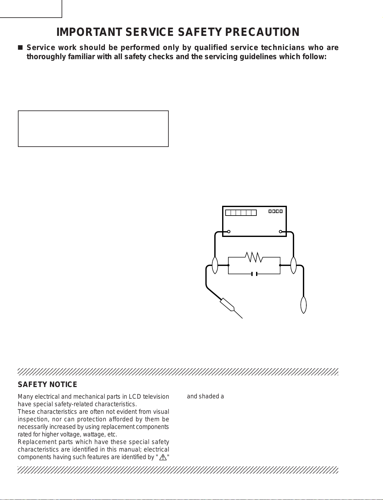
3. To be sure that no shock hazard exists, check for
leakage current in the following manner.
• Plug the AC cord directly into a 220~240 volt AC outlet.
• Using two clip leads, connect a 50k ohm, 10 watt
resistor paralleled by a 0.15µF capacitor in series with
all exposed metal cabinet parts and a known earth
ground, such as electrical conduit or electrical ground
connected to an earth ground.
• Use an AC voltmeter having with 5000 ohm per volt,
or higher, sensitivity or measure the AC voltage drop
across the resistor.
• Connect the resistor connection to all exposed metal
parts having a return to the chassis (antenna, metal
cabinet, screw heads, knobs and control shafts,
escutcheon, etc.) and measure the AC voltage drop
across the resistor.
All checks must be repeated with the AC cord plug
connection reversed. (If necessary, a nonpolarized
adaptor plug must be used only for the purpose of
completing these checks.)
Any reading of 0.75V peak (this corresponds to 0.5
mA. peak AC.) or more is excessive and indicates a
potential shock hazard which must be corrected before
returning the monitor to the owner.
DVM
AC SCALE
50k ohm
10W
0.15 µF
TEST PROBE
TO EXPOSED
METAL PARTS
CONNECT TO
KNOWN EARTH
GROUND
23456789012345678901234567890121234567890123456789012345678901212345678901234567890123456789012
SAFETY NOTICE
Many electrical and mechanical parts in LCD television
have special safety-related characteristics.
These characteristics are often not evident from visual
inspection, nor can protection afforded by them be
necessarily increased by using replacement components
rated for higher voltage, wattage, etc.
Replacement parts which have these special safety
characteristics are identified in this manual; electrical
and shaded areas in the
Schematic Diagrams.
For continued protection, replacement parts must be
identical to those used in the original circuit.
The use of a substitute replacement parts which do not
have the same safety characteristics as the factory
recommended replacement parts shown in this service
manual, may create shock, fire or other hazards.
components having such features are identified by " å"
23456789012345678901234567890121234567890123456789012345678901212345678901234567890123456789012
23456789012345678901234567890121234567890123456789012345678901212345678901234567890123456789012
2
Replacement Parts Lists and
Page 3
LC-13SH1E
LC-15SH1E
Precautions for using lead-free solder
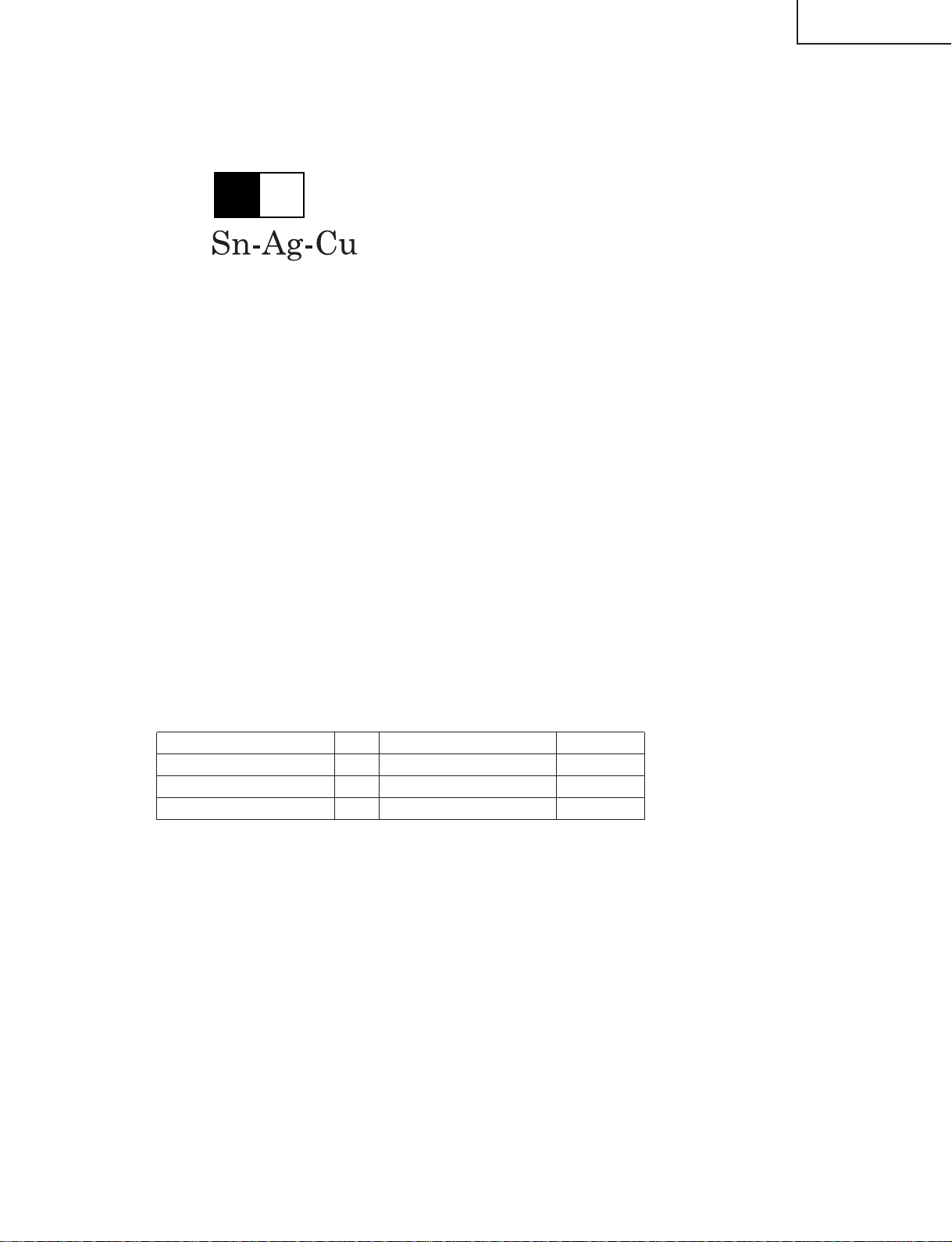
1 Employing lead-free solder
"MAIN PWB" of this model employs lead-free solder. The LF symbol indicates lead-free solder, and is attached on
the PWBs and service manuals. The alphabetical character following LF shows the type of lead-free solder.
Example:
L Fa
Indicates lead-free solder of tin, silver and copper.
2 Using lead-free wire solder
When fixing the PWB soldered with the lead-free solder, apply lead-free wire solder. Repairing with conventional
lead wire solder may cause damage or accident due to cracks.
As the melting point of lead-free solder (Sn-Ag-Cu) is higher than the lead wire solder by 40°C, we recommend
you to use a dedicated soldering bit, if you are not familiar with how to obtain lead-free wire solder or soldering bit,
contact our service station or service branch in your area.
3 Soldering
As the melting point of lead-free solder (Sn-Ag-Cu) is about 220°C which is higher than the conventional lead
solder by 40°C, and as it has poor solder wettability, you may be apt to keep the soldering bit in contact with the
PWB for extended period of time. However, Since the land may be peeled off or the maximum heat-resistance
temperature of parts may be exceeded, remove the bit from the PWB as soon as you confirm the steady soldering
condition.
Lead-free solder contains more tin, and the end of the soldering bit may be easily corroded. Make sure to turn on
and off the power of the bit as required.
If a different type of solder stays on the tip of the soldering bit, it is alloyed with lead-free solder. Clean the bit after
every use of it.
When the tip of the soldering bit is blackened during use, file it with steel wool or fine sandpaper.
Be careful when replacing parts with polarity indication on the PWB silk.
Lead-free wire solder for servicing
Part No. ★ Description Code
ZHNDAi123250E J φ0.3mm 250g(1roll) BL
ZHNDAi126500E J φ0.6mm 500g(1roll) BK
ZHNDAi12801KE J φ1.0mm 1kg(1roll) BM
3
Page 4
LC-13SH1E
LC-15SH1E
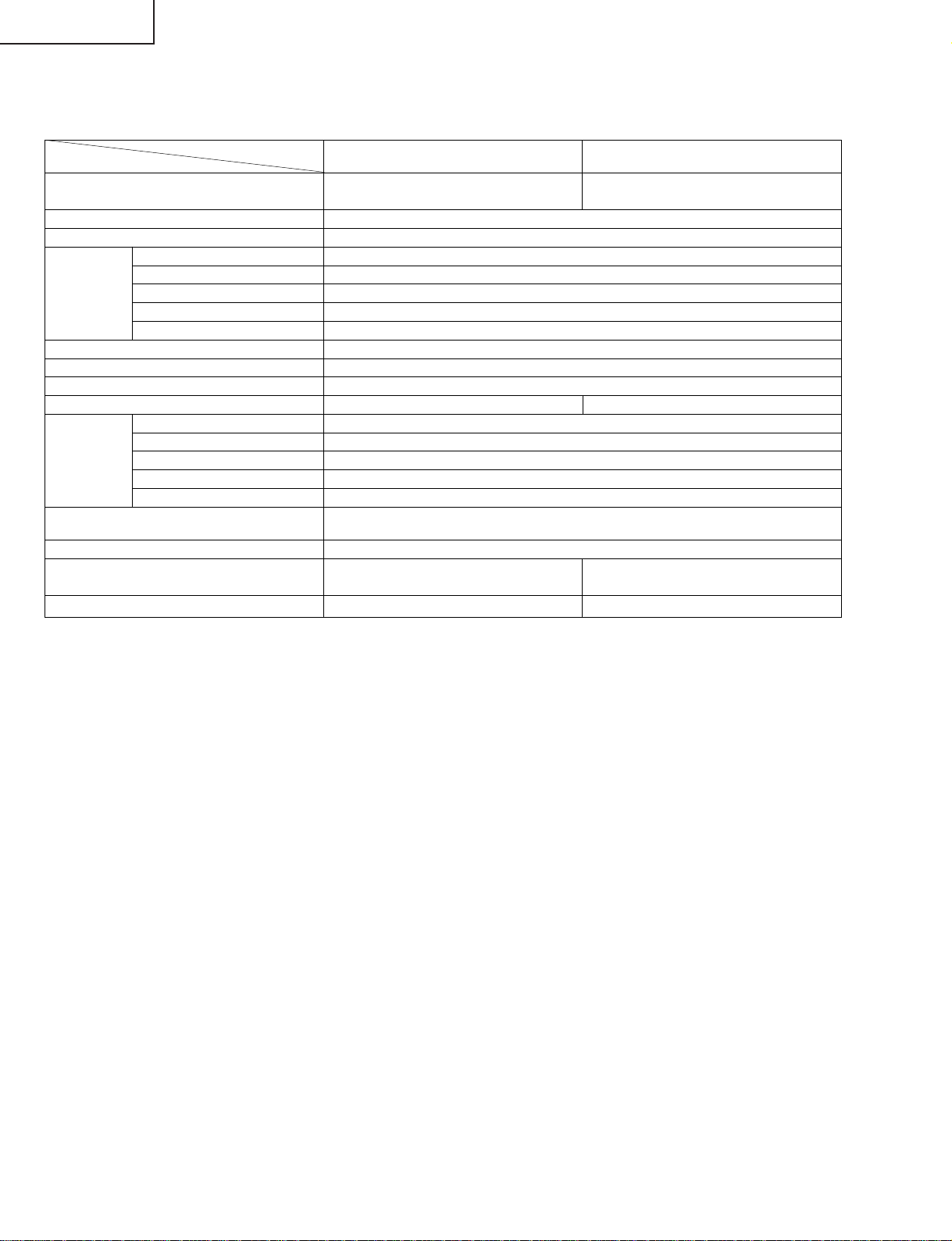
SPECIFICATIONS
Items
LCD panel
Number of dots 921,600 dots
Video colour system PAL/SECAM/NTSC
TV TV-Standard (CCIR) B/G, I, D/K, L/L’
TV-Tuning System Auto preset 200 ch.
STEREO/BILINGUAL NICAM, A2 stereo
AUTO PRESET YES
CATV ~Hyper Band
Brightness 430 cd/m
Viewing angles H: 170° V: 170°
Audio amplifier 2.1 W × 2
Speakers 7.5 cm × 3 cm 2 pcs. 11 cm × 4 cm 2 pcs.
Terminals EXT1 21-pin Euro-SCART
EXT2 S-VIDEO, VIDEO, AUDIO
OUT AUDIO
Antenna DIN
Headphones 3.5 mm ø jack (side)
OSD language English/Spanish/German/French/Italian/Swedish/Dutch/Russian/Portuguese/
Power requirement AC 220 V–240 V, 50/60 Hz
Power consumption 55 W (1.0 W Standby) 59 W (1.0 W Standby)
Weight (approx.) 3.6 kg, w/o accessories 4.1 kg, w/o accessories
Model
13" Advanced Super View 15" Advanced Super View
& BLACK TFT LCD & BLACK TFT LCD
Turkish/Greek/Finnish/Polish
AC 220 V–240 V AC 220 V–240 V
LC-13SH1E LC-15SH1E
2
■ As a part of policy of continuous improvement, SHARP reserves the right to make design and specification changes for product
improvement without prior notice. The performance specification figures indicated are nominal values of production units. There may be
some deviations from these values in individual units.
4
Page 5
OPERATION MANUAL
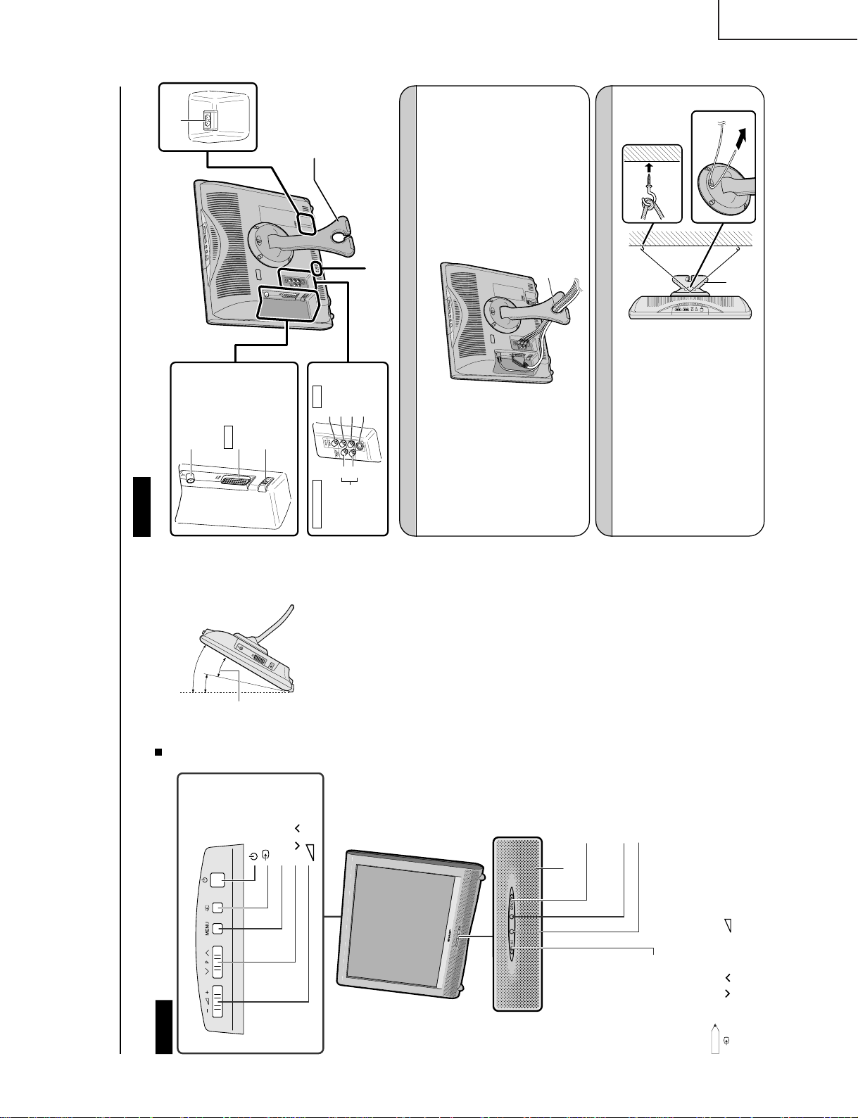
Part Names of the Main Unit
Controls
NOTE
•
(Input), P (
)/(
)(Channel),
(–)/(+) (Volume) and MENU on the control panel of the main unit have the same functions as
the same buttons on the remote control. Fundamentally, this operation manual provides a description based on operation using th
e
remote control.
OPC sensor
Remote sensor
OPC (Optical Picture Control) indicator
The OPC indicator lights up green when the “Backlight” is set
to “Auto (OPC)”.
STANDBY/ON indicator
STANDBY/ON indicator lights up green when the power is on, and red when in
the standby mode (the indicator will not light when the main power is off).
The screen angle can be tilted backwards
between 12 and 30 degrees. (It cannot be
set to vertical.) When changing the angle,
make sure to hold the stand and adjust the
screen to the best viewable angle.
(MAIN POWER)
Upper control panel
(Input)
MENU
P (
)/(
) (Channel)
(–)/(+) (Volume)
How to adjust the angle
12°
30°
Adjustable range
Speaker
The examples used throughout this manual are based on the LC-20SH1E model.
Terminals
Stand
AC INPUT
terminal
Round lock for Kensington
Security Standard slot
Rear View
Antenna terminal
EXT1
Headphone jack
RGB
(21-pin Euro-SCART)
AUDIO OUT
AUDIO OUT
EXT2
(L)
(R)
VIDEO
AUDIO (L)
AUDIO (R)
S-VIDEO
How to Fix the Cables
Pull the cables connected to each terminal. Insert the cables into the stand hole and fix the cables.
How to Prevent the LCD TV Set from Falling Over
To prevent the LCD TV set from falling over in case
of earthquakes and so on, strap it onto the wall by
threading one end of the string through the loop of
the stand (1) and fastening the LCD TV set with
the string attached to the hook on the wall or the
post, etc. (2).
(An example of strapping the LCD TV set onto the
wall is shown on the right.)
• The string and hook are commercially available.
2
1
Stand
Stand hole
LC-13SH1E
LC-15SH1E
5
Page 6
LC-13SH1E
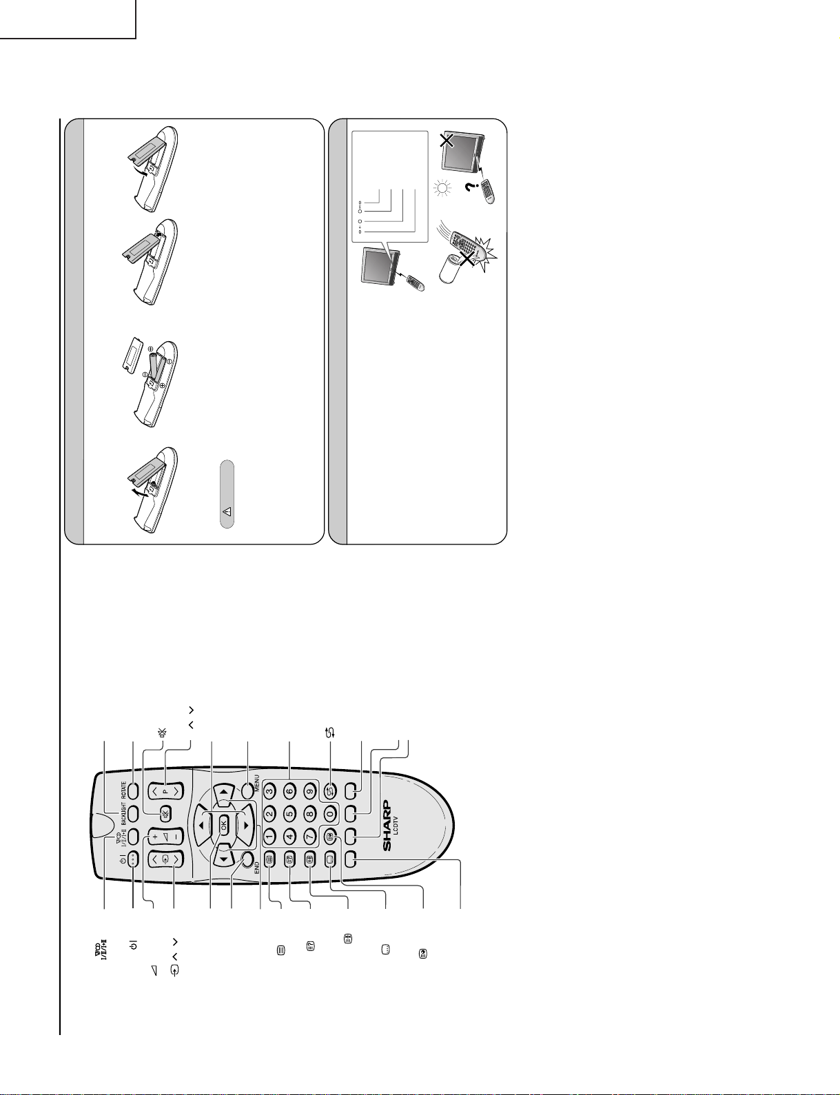
Part Names of the Remote Control
(Sound)
Switches to the sound mode.
BACKLIGHT
Selects the brightness and
OPC of the display.
ROTATE
Rotates the display in every
direction.
Upwards/Downwards
Selection, Zoom display
function (Teletext mode)
(Mute)
Switches the sound on and off.
(Power)
MENU
Displays the menu.
Returns to the previous screen.
(Flashback)
Returns to the previous channel.
Channel Select
Blue, Status Display
Turns on the status display
when the menu is not displayed.
Yellow
(+)/(
-
)
(
Volume
)
( )/( ) (Input)
Switches the input source
between EXT1, EXT2
and TV modes.
OK, Programme Table
END
Returns to normal screen.
Right/Left Selection
(Teletext)
Displays the Teletext mode
screen.
(Reveal)
Displays hidden information
such as solutions to riddles
and puzzles.
(Hold)
Temporarily holds the
current Teletext page.
(Subtitle)
Displays the Teletext
Subtitle directly.
(Subpage)
Displays the Teletext
Subpage directly.
Red, Picture Menu
Green, Sound Menu
P ( )/( ) (Channel)
Installing Batteries in the Remote Control
Before using the LCD TV set for the first time, install the two
“AA” size batteries (supplied) in the remote control. When the
batteries become depleted and the remote control fails to operate, replace the batteries with new
“AA” size batteries.
1
Open the battery cover.
2
Insert two “AA” size batteries.
3
Close the battery cover.
• Place batteries with their
terminals corresponding
to the (+) and (
–)
indications in the battery
compartment.
Caution!
Precautions regarding batteries
Improper use of batteries can result in a leakage of chemicals and/or explosion. Be sure to follow the instructions below.
• Place batteries with their terminals corresponding to the (+) and (
–) indications.
• Different types of batteries have different characteristics. Do not mix batteries of different types.
• Do not mix old and new batteries. Mixing old and new batteries can shorten the life of new batteries and/or cause old
batteries to leak chemicals.
• Remove batteries as soon as they are depleted. Chemicals that leak from batteries can cause a rash. If chemical
leakage is found, wipe it off with a cloth.
• The batteries supplied with the LCD TV set may have a shorter operating time due to storage conditions.
• If the remote control is not to be used for an extended period of time, remove the batteries from the remote control.
• Align the tab on the battery cover (
1) and place
it while pressing the tab (
2) to close it.
Using the Remote Control
Use the remote control by pointing it towards the remote sensor
window of the main unit. Objects between the remote control and
sensor window may prevent proper operation.
Cautions regarding use of the remote control
• Do not apply shock to the remote control. In addition, do not
expose the remote control to liquids, and do not place it in an area
with high humidity.
• Do not install or place the remote control under direct sunlight. The
heat may cause deformation of the unit.
• The remote control may not work properly if the remote sensor
window is under direct sunlight or strong lighting. In such a case,
change the angle of the lighting or main unit, or operate the remote
control closer to the remote sensor window.
• Detach the cover
while pressing the
(
"
) part.
STANDBY/ON
indicator
OPC indicator
Remote sensor
OPC sensor
2
Preparation
1
LC-15SH1E
6
Page 7
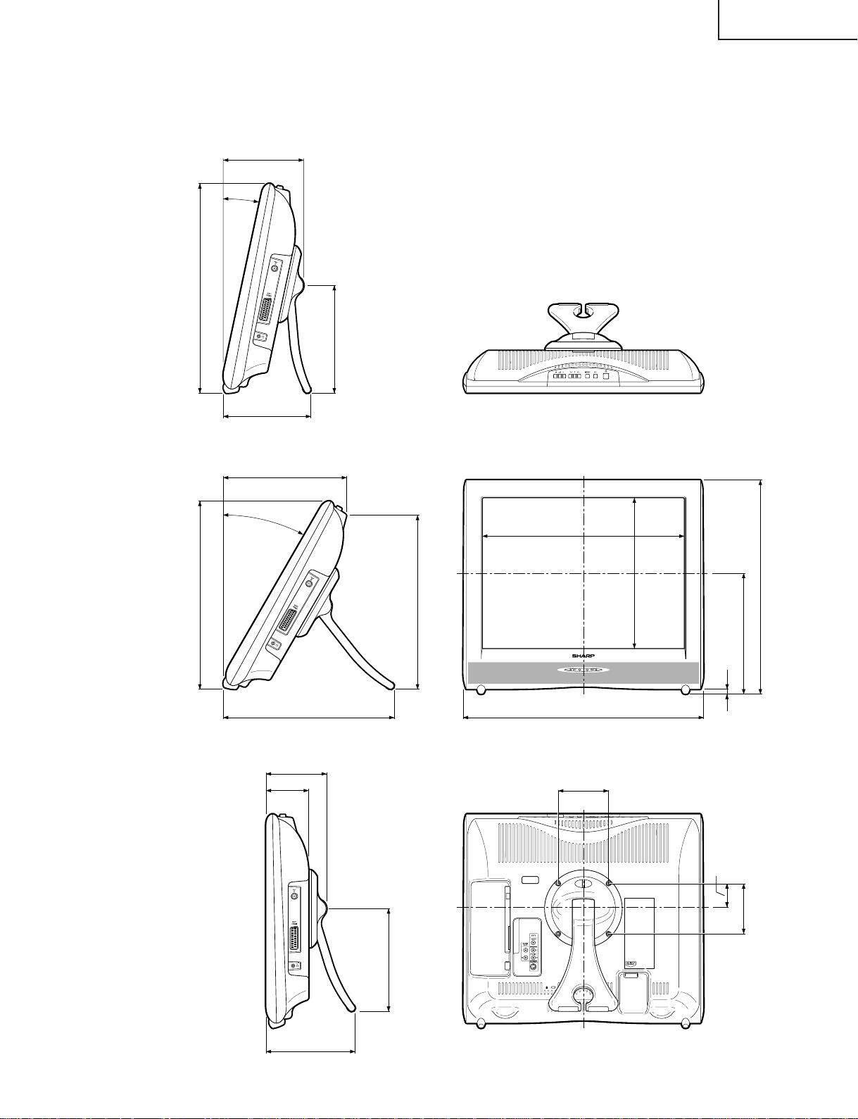
DIMENSIONS
ËLC-13SH1E/LC-15SH1E
LC-13SH1E
LC-15SH1E
312/344
143/145
12°
153/155
30°
Unit: mm
163/167
196/205
267/307
282/311
277/281
115/115
79/79
152/158
259/282
309/351
200.9/231
181/201/242
10
341/384
100
52.3/37.4
100
157/158
7
Page 8
LC-13SH1E
LC-15SH1E
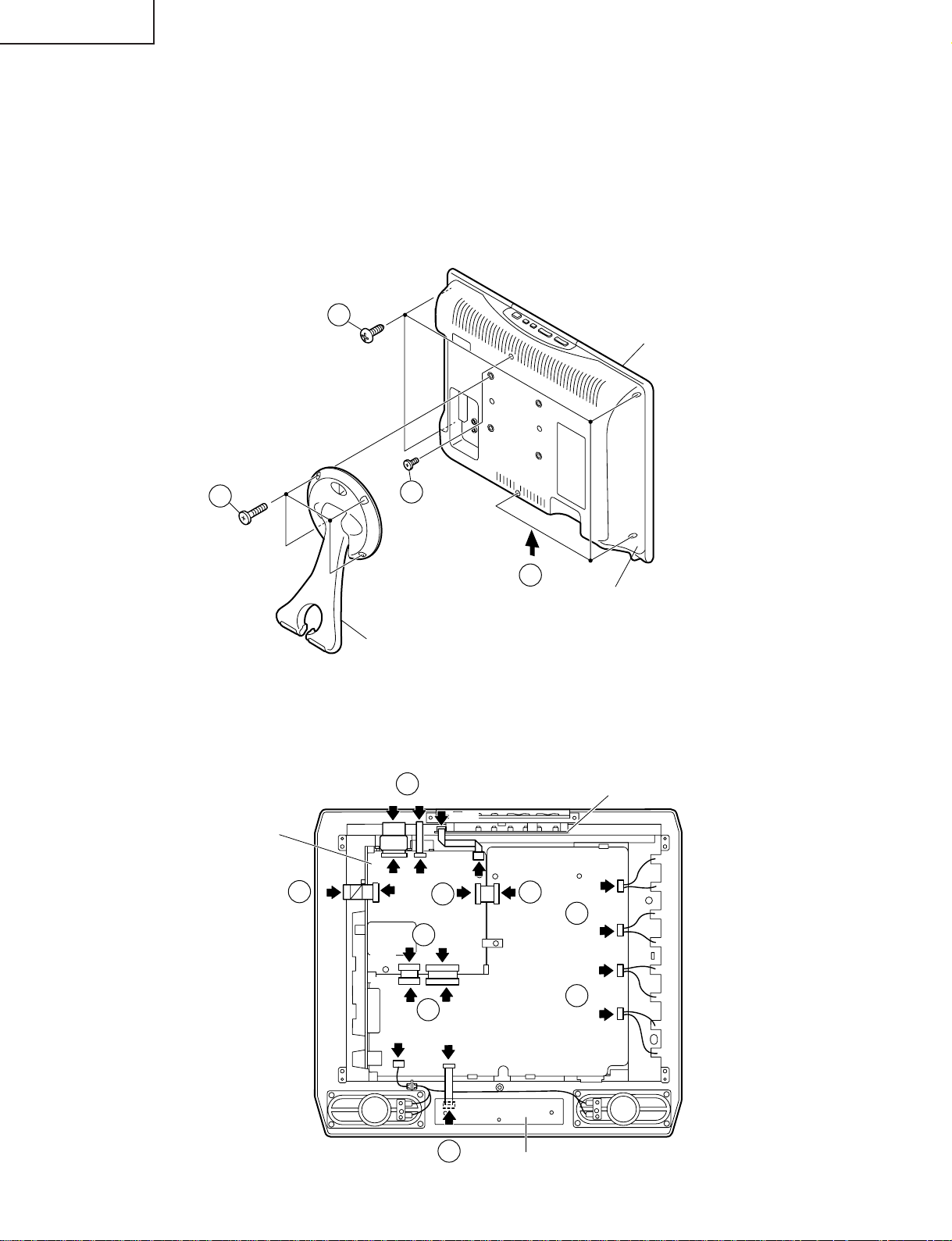
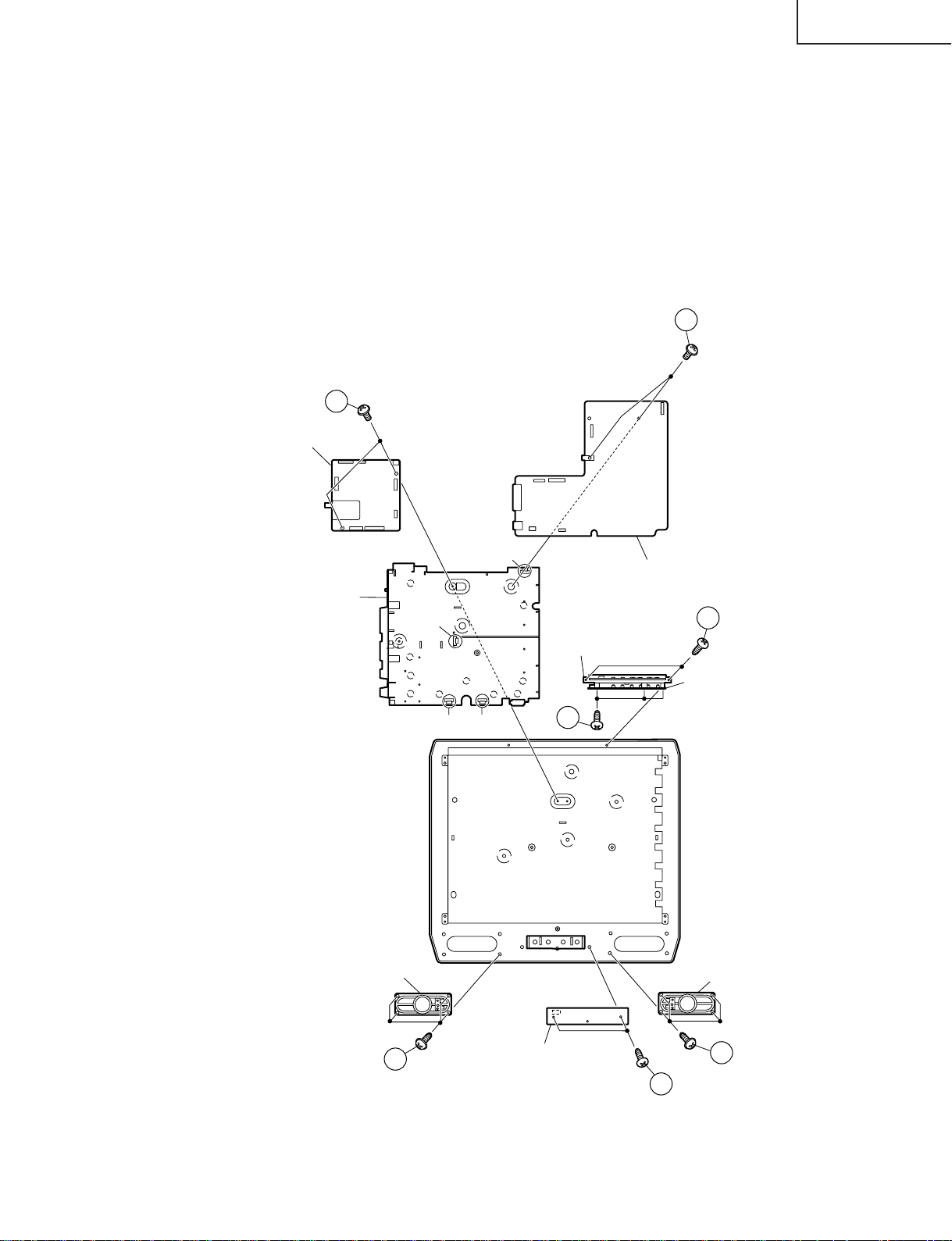
REMOVING OF MAJOR PARTS
1. Remove the stand fixing screws (4 pcs.).
2. Remove the cabinet B fixing screws (6 pcs.).
3. Remove the cabinet B after opening from the direction of an arrow.
4. Detach the connector from each PWB.
2
Cabinet A
1
Main PWB
2
3
Cabinet B
Stand
4
CN2
CN3
SC4201
SC105
SC1201
SC1202
4
CN1
SC1203
4
SC102
P7701
4
SC104
P3901
SC106
P3902
Operation PWB
P6700
4
4
P6701
P6702
4
P3301
4
SC3601
Sub PWB
P6703
SC4001
4
R/C,LED PWB
8
Page 9
LC-13SH1E
LC-15SH1E
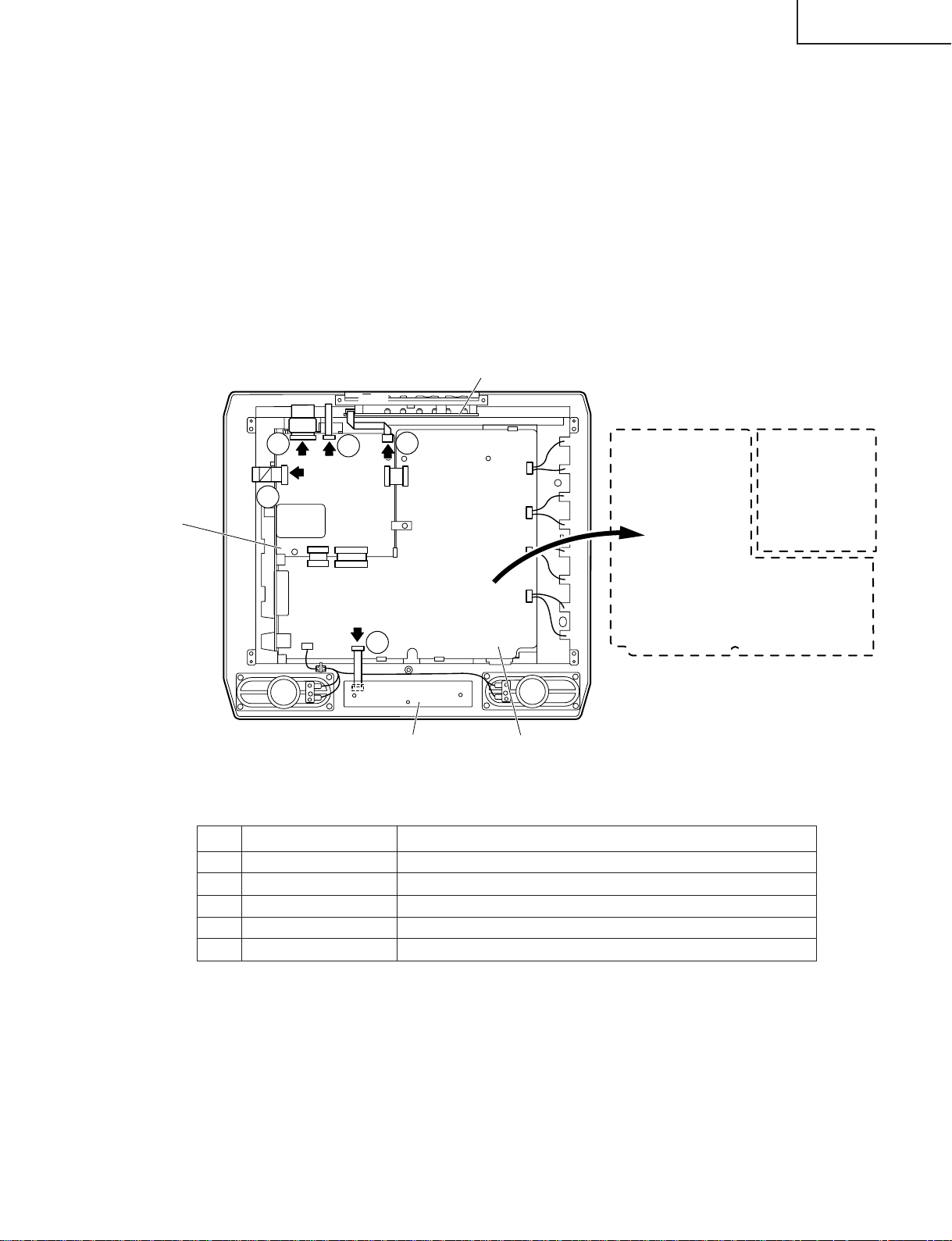
5. Remove the 2 lock screws from the main PWB and undo the hooks a. Detach the chassis frame, together with its
terminals, from the main PWB.
6. Remove the 2 lock screws from the sub PWB and undo the hooks b, c and d. Detach the chassis frame together
with its terminals, from the sub PWB.
7. Remove the 2 lock screws from the R/C, LED PWB and take out the R/C, LED PWB.
8. Remove the 2 lock screws from the operation panel (top cover), and detach the operation panel (top cover).
9. Remove the 3 lock screws from the operation PWB, and detach the operation PWB.
10. Remove the 4 lock screws each from the right and left speakers and take out both the speakers.
6
5
Main PWB
Chassis Frame
Speaker (R)
d
a
c
b
Operation panel
(Top Cover)
9
Sub PWB
8
Operation
PWB
Speaker (L)
10
R/C,LED PWB
9
10
7
Page 10
LC-13SH1E
LC-15SH1E
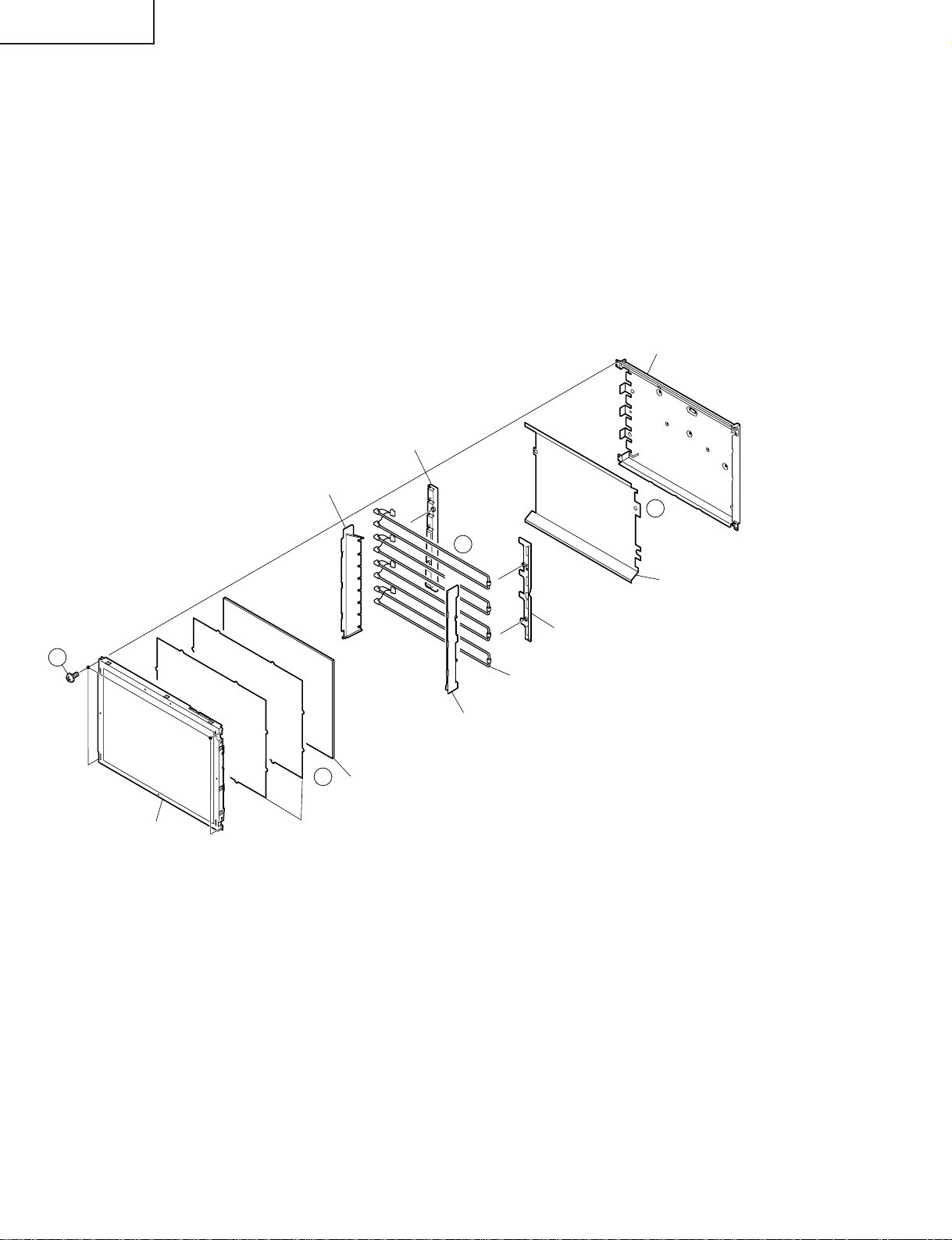
» Precautions in handling the LCD panels
1. Work in a clean room (with humidities below 50%).
2. Be sure to wear an anti-static armband.
3. Handle the panels on an electro-conductive mat.
4. Be careful not to fall, shake and shock the panels.
11. Remove the 4 lock screws from the LCD panel and detach the LCD panel.
12. Remove the diffusion sheets and diffusion plate.
13. Detach the lamp holders -R (top), -L (top) and -R (bottom), -L (bottom) from the lamp unit.
14. Detach the reflection sheet from the back shield.
Back shield
(PSLDMA541WJFW:LC-15SH1E)
(PSLDMA542WJFW:LC-13SH1E)
Lamp Holder -L (Bottom)
(LHLDZA426WJKZ:LC-15SH1E)
(LHLDZA435WJKZ:LC-13SH1E)
Lamp Holder -L (Top)
(LHLDZA423WJKZ:LC-15SH1E)
(LHLDZA434WJKZ:LC-13SH1E)
14
11
LCD Panel Unit
Lamp Holder -R (Top)
(LHLDZA424WJKZ:LC-15SH1E)
(LHLDZA433WJKZ:LC-13SH1E)
12
Diffusion Plate
(PCOVUA046WJZZ:LC-15SH1E)
(PCOVUA047WJZZ:LC-13SH1E)
Diffusion Sheet, x2
(PSHEPA227WJZZ:LC-15SH1E)
(PSHEPA230WJZZ:LC-13SH1E)
13
Reflection Sheet
(PSHEPA228WJZZ:LC-15SH1E)
(PSHEPA229WJZZ:LC-13SH1E)
Lamp Holder -R (Bottom)
(LHLDZA425WJKZ:LC-15SH1E)
(LHLDZA429WJKZ:LC-13SH1E)
Lamp Unit, x4
(KLMP-A048WJZZ:LC-15SH1E)
(KLMP-A047WJZZ:LC-13SH1E)
10
Page 11
LC-13SH1E
SC1203
SC1201
SC1202
SC105
SC3601
CN1
CN2
CN3
SC4201
SC4001
2
3
1
4
5
Main PWB
Operation PWB
Main PWB
(Side B)
Sub PWB
(Side B)
Sub PWB
R/C, LED PWB
LC-15SH1E
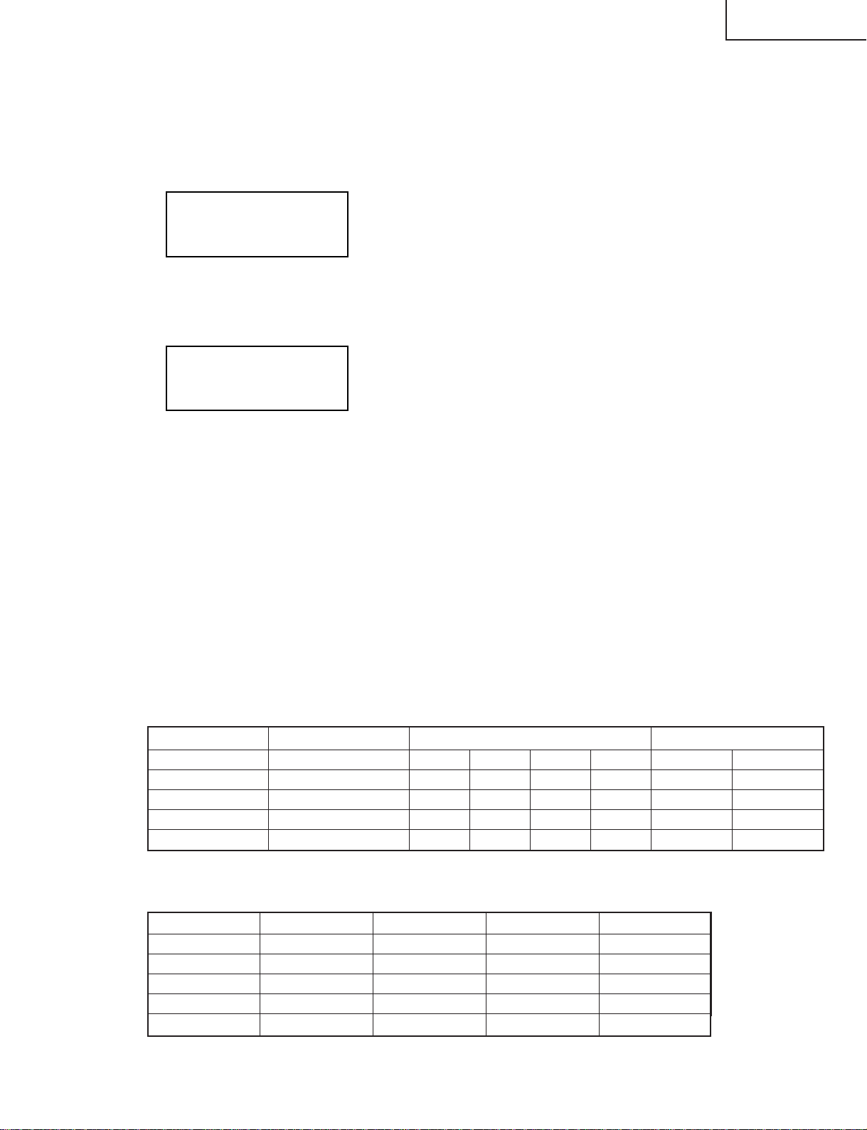
» Precautions at the time of the side B(back) service of main and sub unit.
1. Remove only SC1203 of the FFC for connection between Main unit (SC1203) and LCD panel, and connect the
extended cable (QCNW-A553WJZZ) for service.
2. Remove only SC1202 of the FFC for connection between Main unit (SC1202) and LCD panel, and connect the
extended cable (QCNW-B556WJZZ) for service.
3. Remove only SC1201 of the FFC for connection between Main unit (SC1201) and LCD panel, and connect the
extended cable (QCNW-A555WJZZ) for service.
4. Remove only SC105 of the FFC for connection between Main unit (SC105) and Operation unit (SC4201), and
connect the extended cable (QCNW-D444WJQZ) for service.
5. Remove only SC3601 of the FFC for connection between Sub unit (SC3601) and R/C, LED unit (SC4001), and
connect the extended cable (QCNW-D445WJQZ) for service.
6. Remove the PWB unit fixing screws (main unit : 2pcs, sub unit : 2pcs., inverter unit : 3pcs.)
Step Part No. Description
1 QCNW-A553WJZZ Extension Cable 30-pin Main (SC1203)-LCD Panel
2 QCNW-A556WJZZ Extension Cable 50-pin Main (SC1202)-LCD panel
3 QCNW-A555WJZZ Extension Cable 20-pin Main (SC1201)-LCD panel
4 QCNW-D444WJQZ Extension Cable 5-pin Operation (SC4201)-Main (SC105)
5 QCNW-D445WJQZ Extension Cable 8-pin R/C, LED (SC4001)-Sub (SC3601)
11
Page 12

LC-13SH1E
LC-15SH1E
ADJUSTING PROCEDURE OF EACH SECTION
The best adjustment is made before shipping. If any position deviation is found or after part replacement is
performed, adjust as follows.
Preparation for adjustments
Use a stable AC power source.
LC-13/15SH1E AC Power : 230V
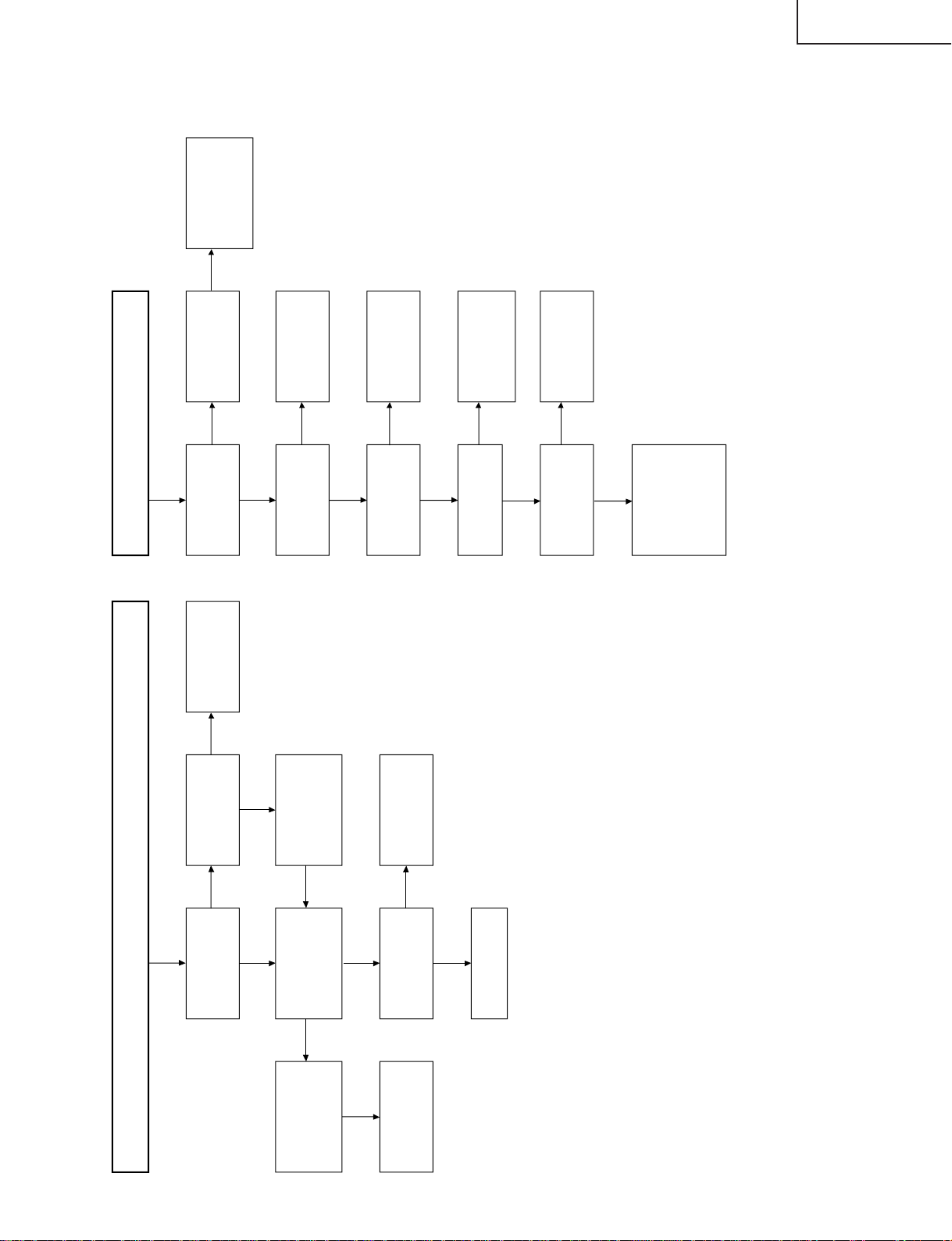
1.Adjusting procedure
Complete Set → Power ON → Enter Adjustment Process Mode → RF AGC adjustment → DCXO adjustment →
Common Bias adjustment → White Balance adjustment
2.Entering the adjustment process mode
• After power on, press the adjustment process mode key on the service remote control.
• Switching on the TV set, holding pushed the "Input" and "Volume (–)" Key at once, the TV set enters in the "K"
mode.
In this condition, pushing "Volume (–)" and "P (Ù)" Key, the adjust mode appears.
3.Key operation in the adjustment process mode
• Use the "UP" or "DOWN" cursor key to select the adjustment mode item.
• Use the "LEFT" or "RIGHT" cursor key to change the data.
4.Initialization
When the EEPROM (IC101) has been replaced or when the EEPROM has been initialized, readjust the each
adjust the each adjustments.
4-1. When the EEPROM has been replaced:
1) Plug in the AC cord to an AC power outlet and turn on the power.
2) When the setting is finished, the LED turns from red to green. In about 15 seconds, the initialization is
completed.
4-2. When initializing the EEPROM data and making readjustments:
1) Enter the Adjustment Process mode.
2) Select the INIT TV item and press the "RIGHT" cursor key to enable the item.
3) Unplug the power cable and plug it again in the AC power outlet. Turn on the power.
4) When the setting is finished, the LED turns from red to green. In about 5 seconds, the initialization is
completed.
<Note>
When the INIT TV item has been enabled in the adjustment process, be sure to unplug the power cable and plug
it in again. Then start adjustments. Otherwise the readjusted data cannot be put in memory.
4-3. Setting the screen size (inches)
1) Enter the Adjustment Process mode.
2) Check the model number.
3) Hold down the "LEFT" or "RIGHT" cursor key longer than 2 seconds, and select the inch size (13):(LC13SH1E) and (15):(LC-15SH1E).
SH1E Main Ver
INCH SIZE 15
Scaler Ver *.**.**
*.**
12
Page 13
5.Adjustment
5-1. RF AGC adjustment
1) Feed the colour bar signal.
2) In Adjustment Mode, select the RF AGC AUTO ("OFF") and press the " RIGHT" cursor key to start the
adjustment.
3) Automatic adjustment is complete when it display "OK" is displayed.
4) RF AGC data will be in the range of 0-63. If "NOK" is displayed, adjustment failed.
LC-13SH1E
LC-15SH1E
SH1E Main Ver
Scaler Ver *.**.**
RF AGC AUTO OK
*.**
RF AGC Auto adjustment complete
RF AGC data (Example)
38
5-2. DCXO adjustment
1) Feed the colour bar signal.
2) In Adjustment Mode, select the DCXO AUTO ("OFF") and press " RIGHT" cursor key to start the adjustment.
3) Automatic adjustment is complete when "OK" is displayed. If "NOK" is displayed, adjustment failed.
SH1E Main Ver
DCXO AUTO OK
Scaler Ver *.**.**
*.**
DCXO Auto adjustment complete
DCXO data
**
5-3. Common bias adjustment
1) Select the EXT-Video input and without signal.
2) In Adjustment Mode, select the COM BIAS and vary the data until the contrast becomes the sharpest.
(Black looks most sinking.)
5-4. White balance adjustment
[A] White balance pre-adjustment
1) Feed the 100% white signal.
2) In Adjustment Mode, select the AWBSD ("OFF") and press the " RIGHT" cursor key to start the adjustment.
3) Automatic adjustment is complete when "OK" is displayed.
[B] White balance adjustment
Adjust "R CUTOFF2", "G CUTOFF2", "B CUTOFF2", "WB R GAIN", "WB G GAIN" and "WB B GAIN" in the
adjustment processing to obtain the same colour as the standard set.
6.Factory setting
6-1. Make the factory setting using the adjustment remote control.
Model Key Name Remote Control Code OSD Language Setting
A3IK13/15SH1E Shipment Setting 1 1000 0011 1111 110 German (00001 FEh)
A3IK13/15SH1K Shipment Setting 2 1000 0000 1010 110 English (00002 A8h)
A3IK13/15SH1R Shipment Setting 3 1000 0110 1011 110 Russian (00003 EBh)
A3IK13/15SH1F Shipment Setting 4 1000 0100 1011 110 French (00004 E9h)
A3IK13/15SH1I Shipment Setting 6 1000 0000 1011 110 Italian (00005 E8h)
6-2. Different factory settings.
Model Language Country Color System Sound System
A3IK13/15SH1E German Germany PAL B/G
A3IK13/15SH1K English UK PAL I
A3IK13/15SH1R Russian Russia SECAM D/K
A3IK13/15SH1F French France SECAM L/L'
A3IK13/15SH1I Italian Italy PAL B/G
13
Page 14
LC-13SH1E
LC-15SH1E
7. Lamp error detection
7-1. Functional description
This LCD colour television has a function (lamp error detection) to be turned OFF automatically for safety
when the lamp or lamp circuit is abnormal.
If the lamp or lamp circuit is abnormal, or some other errors happen, and the lamp error detection is executed,
the followings occur.
1 The main unit of television is turned OFF 5 seconds after it is turned ON. (The power LED on the front
side of TV turns from green to red.)
2 If the situation 1 happens 5 times sequentially , television can not be turned ON. (The power LED remains
red.)
7-2. Countermeasures
7-2-1.Check when turning OFF the lamp error detection
If the power has been turned off 5 times because of lamp error , hold down the unit’s "INPUT" and "Volume
(–)" kye simultaneously and turn on the unit’s power switch. The TV set gets back on power in the "K"
mode.
In this state, press the unit’s "V olume (–)" and "P (Ù)" key simultaneously. The Adjustment Process mode
shows up.
This enables the operation check to detect errors in the lamp or lamp circuit.
Check whether "ERROR NO RESET" of the adjustment process is 1 or more. If it is 1 or more, it indicates
the lamp error detection was executed.
7-2-2.Resetting of the lamp error count
After confirming that the lamp or lamp circuit is normal, reset the lamp error count. Select "ERROR NO
RESET" of the adjustment process and set the number to 0 using the "LEFT" or "RIGHT" cursor key.
SH1E Main Ver *.**
ERROR NO RESET 5
Afterwards, perform the operation check to confirm that the lamp error detection does not function.
Scaler Ver *.**.**
Reset 0
14
Page 15

8. Hotel mode
8-1. How to enter the Hotel mode.
1) Turn on the power and enter the Adjustment Process mode.
2) Using the "UP" or "DOWN" cursor key on the remote controller, select the Hotel mode.
3) Using the "RIGHT" cursor key on the remote controller, change the setting from "0" to "1". Now the
Hotel mode shows up.
Adjustment Process menu
LC-13SH1E
LC-15SH1E
Hotel mode = "0"
Hotel mode 0
EXT CONTROL OFF
Hotel mode = "1"
Hotel mode 1
Max. volume **
On program ***
EXT CONTROL OFF
4) Using the "UP" or "DOWN" cursor key on the remote controller, select "Max. volume" and "On program".
Make the setting with the "LEFT" or "RIGHT" cursor key.
5) Finally quit the Adjustment Process mode and turn off the power. The TV set comes on in the Hotel mode
after the next switch-on.
8-2. Hotel mode settings
1) Max. volume (0-60)
You can set the maximum volume at your desired level.
2) On program (0-199)
You can select a desired channel when switching on the TV set.
8-3. Canceling the Hotel mode
1) Turn on the power and enter the Adjustment Process mode.
2) Using the "UP" or "DOWN" cursor key, select the Hotel mode.
3) Using the "LEFT" cursor key, change the setting from "1" to "0".
4) Finally quit the Adjustment Process mode and turn off the power. The TV set comes on out of the Hotel
mode after the next switch-on.
15
Page 16
LC-13SH1E
LC-15SH1E
9. Software Loading
1) Upgrading the software or after replacement of IC151, IC501 or Main PWB, make sure to upload the processors
with updated software.
2) Please use the dedicated Interface JIG (JIGINF-001) and supplied programs for upgrading the software.
3) This model employs two software;
• SCALER microprocessor software
• MAIN microprocessor software
Please upload the SCALER microprocessor software first follow by MAIN microprocessor software.
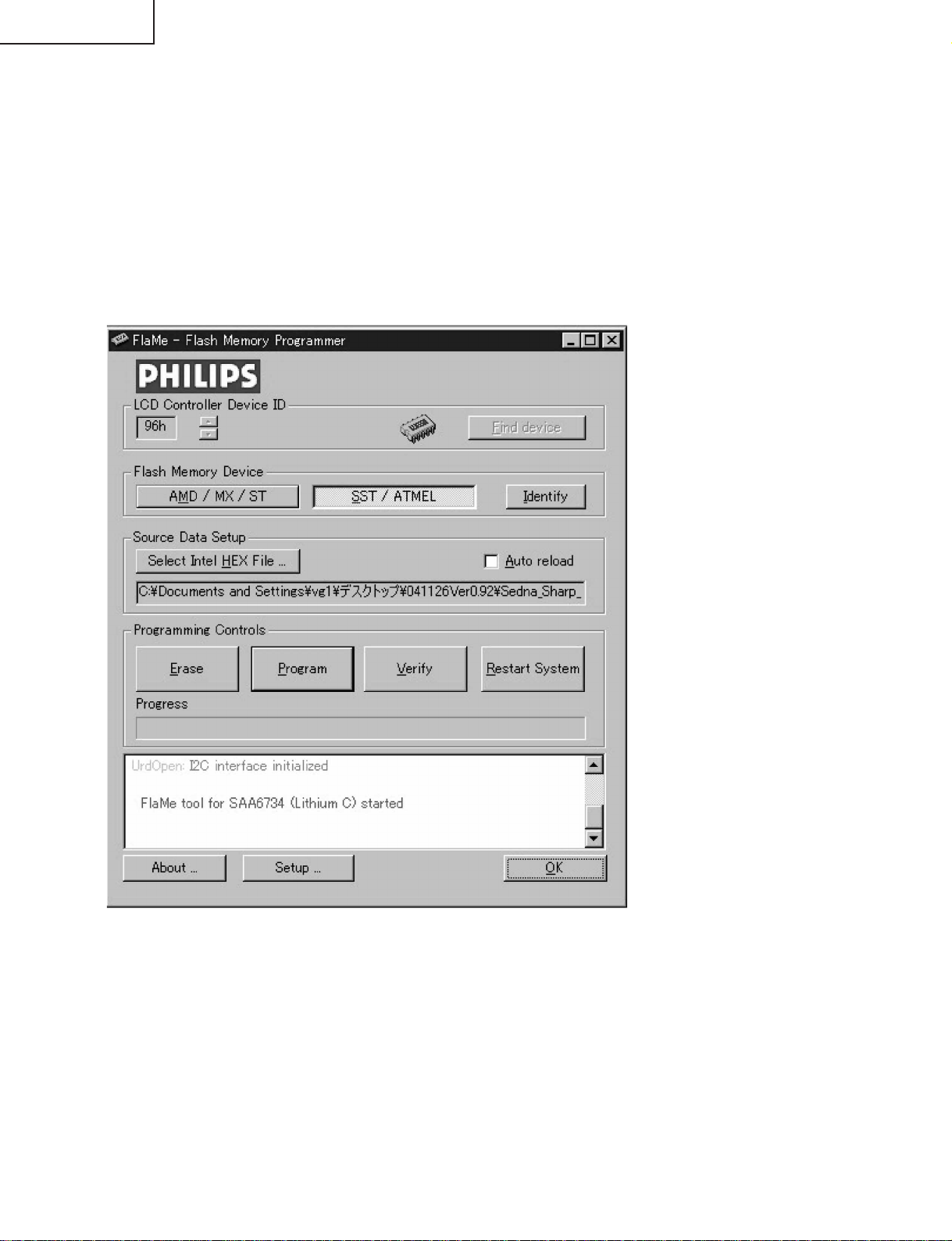
1. SCALER microprocessor
1) Set Interface JIG switch to position "SCALER".
2) Power ON the set and plug Interface JIG connector to P2002.
3) Run the ISP_Tool.exe program.
16
Page 17
LC-13SH1E
LC-15SH1E
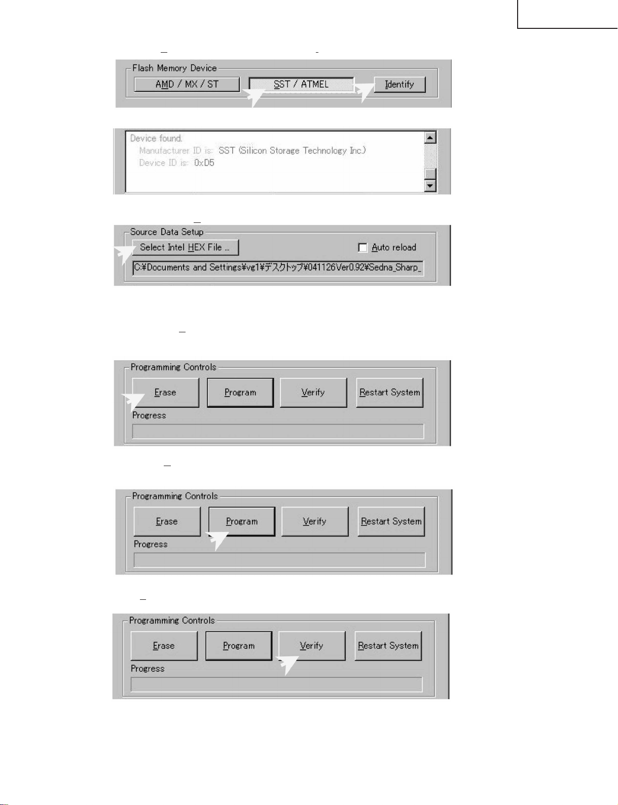
4) First click [SST / ATMEL] and then follow by [Identify] to identify the flash memory.
Confirm the item below in Comment Window.
5) Click [Select Intel HEX File …] to open the source files. The source file name are "Sedna_Sharp****.hex"
Confirm the source file is loaded correctly.
6) Next click the [Erase] to erase all the data in the flash memory. Confirm the erase process is complete
without any error.
7) Then click [Program] to start uploading the source file into the flash memory. After uploading process is
complete, confirm there are no error.
8) Click [Verify] to verify the uploaded data and confirm there are no error.
17
Page 18
LC-13SH1E
LC-15SH1E
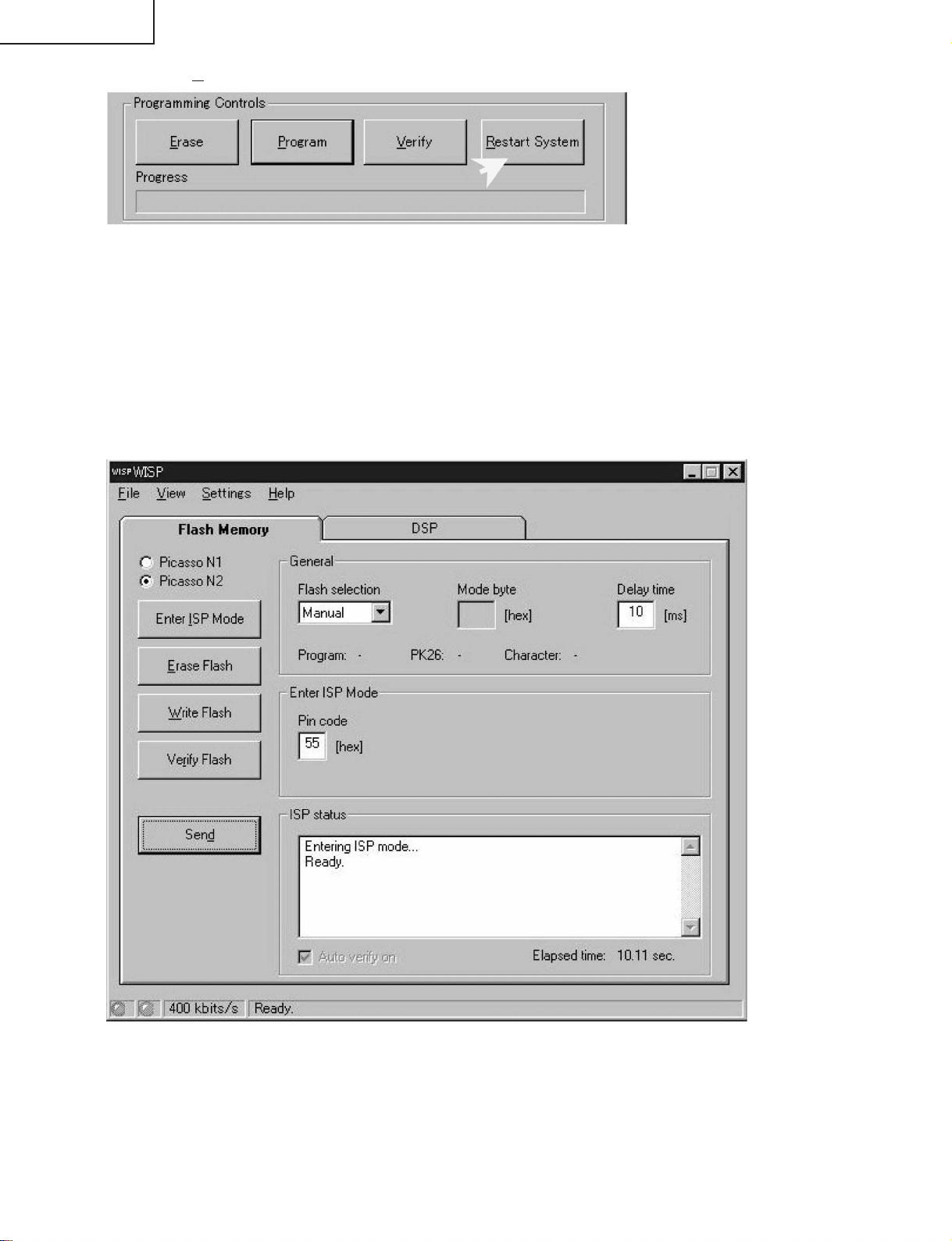
9) Finally click [Restart System] to initialize. Confirm "Reset done" in Comment Window.
10) Power OFF the set by unplugging AC Cord, remove the JIG from the plug and wait for 1 minute before
power ON again.
Notes: If any error occur during any process, power OFF the set and repeat the all the process again. If
these still fail, please erase Main Software and repeat the whole process again. To erase Main software,
please refer to MAIN microprocessor step No. 1) to 5) only.
2. MAIN microprocessor
1) Set JIG switch to position "LOC".
2) Power ON the set and plug Interface JIG connector to P2002.
3) Run the WISP.exe program.
18
Page 19
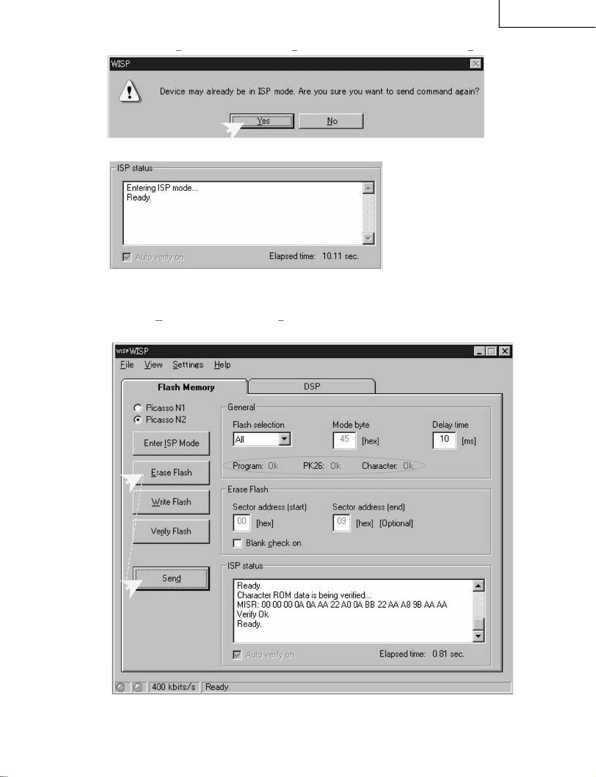
4) First click [Enter ISP Mode] then click [Send]. If the following window appear, click [Yes]
Confirm ISP status "Ready".
If "Entering ISP is not successful" occur, repeat step No. 4) again. If still fail, unplug the AC cord and
repeat from step No. 2) again.
LC-13SH1E
LC-15SH1E
5) Then click [Erase Flash], follow by [Send]. Confirm the Program, PK26 & Character are all "OK" and ISP
status is "Ready".
If "Failed" occur, unplug the AC cord and repeat the whole process again from beginning.
19
Page 20
LC-13SH1E
LC-15SH1E
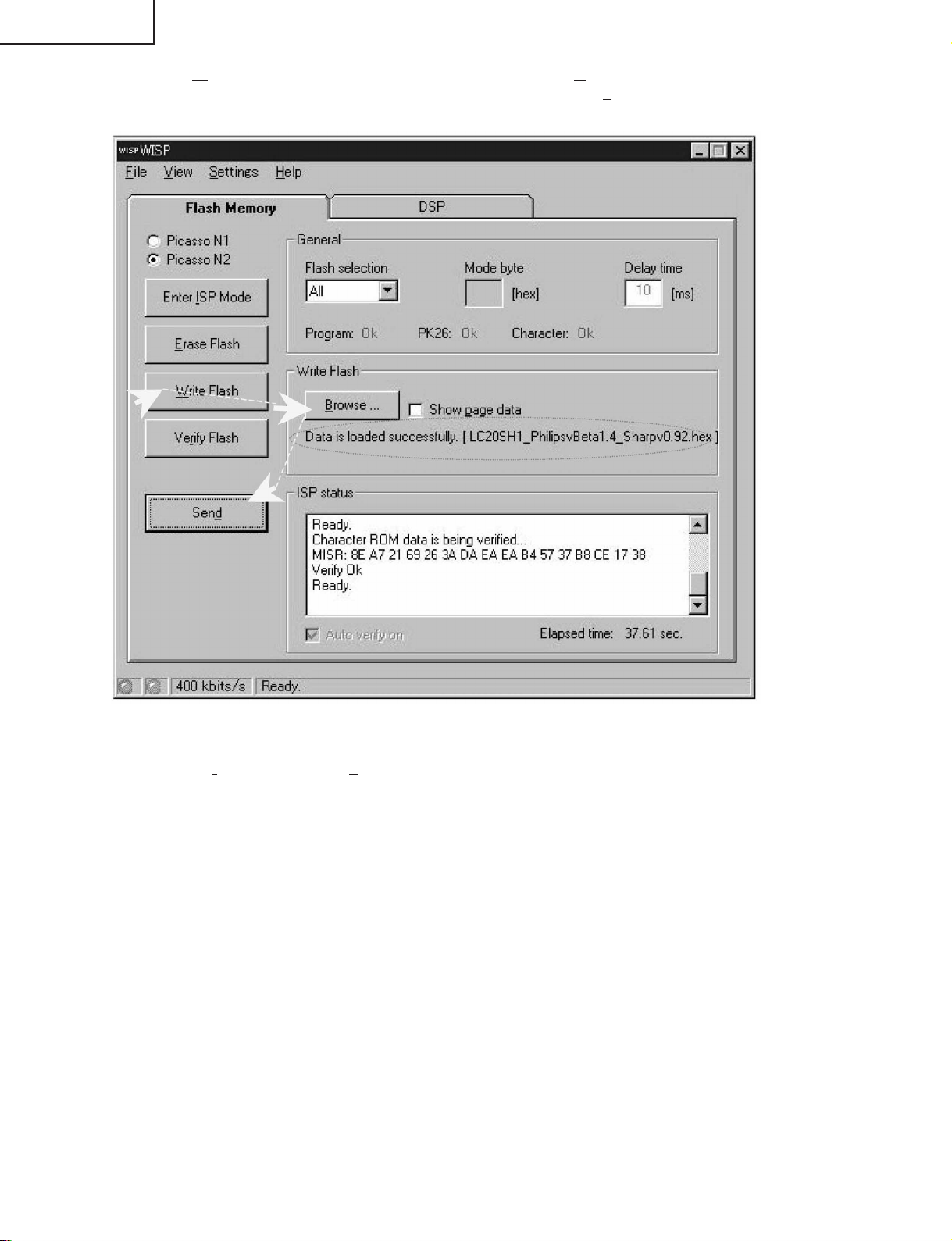
6) Next click [Write Flash] and load the source file by clicking [Browse]. The source file name are
"LC20SH1_****.hex". Once the data is loaded successfully click [Send]. Confirm the Program, PK26 &
Character are all "OK" and ISP status is "Ready".
If "Failed" occur, unplug the AC cord and repeat the whole process again from beginning.
7) Finally click [Verify Flash] and [Send] to verify the flash memory. Confirm the Program, PK26 & Character
are all "OK" and ISP status is "Ready". If "Failed" occur, unplug the AC cord and repeat the whole process
again from beginning.
8) Power OFF the set and remove the JIG.
20
Page 21
No No
No Yes
Yes
Yes
Yes
Yes No
No
Yes
No
Yes
Yes
No
No
Yes
No
Yes
No
Yes
No picture and No sound
Back light lamp failure to light up
Replace F7701.
Is Q7702 base
voltage at "L"
state?
Check all output
voltage line for
short circuit.
Do fuse F7701
function?
Are T7701 secondary
output at C7720,
C7721, C7722, C7723
and C7725 voltage
normal?
Check Q6700-
Q6702, Q6707-
Q6709 and their
peripheral parts for
short circuiting.
Is there any short
circuit in INV +B
line?
Check the OFL1
line, OFL2 line,
IC1201 and their
peripheral parts.
Check the OFL line,
Q3600, Q3601 and
their peripheral
parts.
Check Q6700-
Q6702, Q6707-
Q6709 and their
peripheral parts.
Replace the back
light lamp with new
one and check
again.
Do fuse F6700,
F6702 function?
Are the pins (40)
and (138) of IC1201
in the "H" state?
Are the outputs of
Q3600 and Q3601
in the "L" state?
Is the pins (4) and
(7) of T6701-T6704
normal?
Is the pin (10) of
T6701 normal?
Check the error
amp circuit D6705,
D6707, D6710,
D6712, D6715,
D6716, Q6706,
Q6713 and their
peripheral parts.
Remove F7701 and
check the load side.
Is there short-
circuit?
Is there any short-
circuit in T7701
primary side
periphery?
Check IC7702,
IC7704 and their
peripheral parts.
Check IC7701 and
its peripheral parts.
Is T7701 primary
switching waveform at
pin (1) of IC7701
normal?
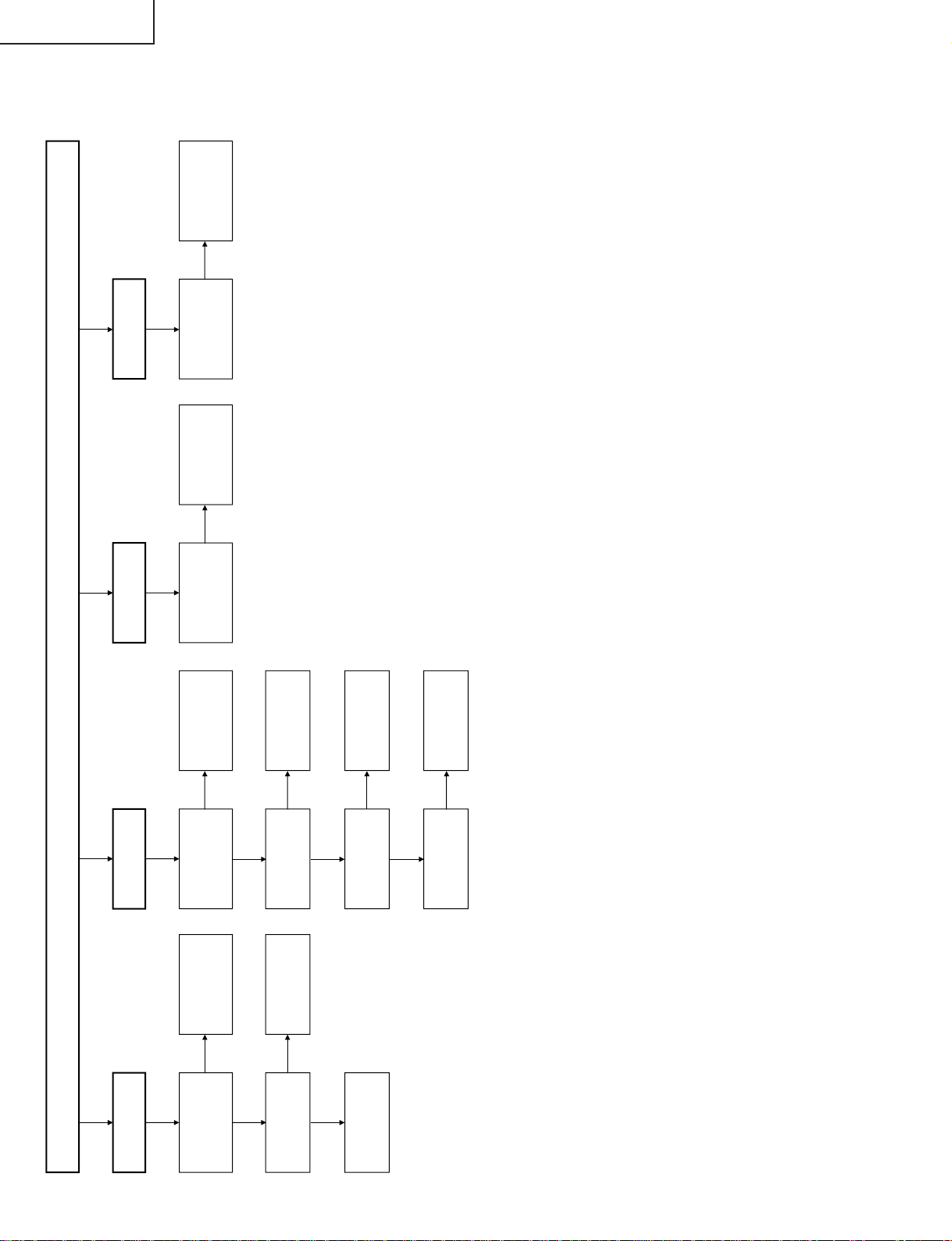
TROUBLE SHOOTING TABLE
LC-13SH1E
LC-15SH1E
21
Page 22
LC-13SH1E
No
No
No
No
Yes
Yes
No
No
Yes
Yes
No
Yes
No
No S-Video
output
No Picture (1/3)
No picture at all.
No Video 2
output
Check the power
line.
No TV output
Is output Q801,
Q802 and Q803
normal?
Is input / output
of IC1201
normal?
Check LCD panel
voltages and
waveform.
Check IC501 and
its peripheral
parts.
Check IC1201
and its peripheral
parts.
Is voltage at pins
(7) and (9) of
tuner normal?
Is output at pin
(11) of tuner
normal?
Is input / output
of SF201
normal?
Is output of
IC801 normal?
Check IC801 and
its peripheral
parts.
Check SF201 and
its peripheral
parts.
Check tuner and
its peripheral
parts.
Is video input at
pin (B21) of
IC501 normal?
Check the V1_V
line and its
peripheral parts.
Is input at pins
(C18) and (D18)
of IC501 normal?
Check the V1_SY
and V1_SC line
and their
peripheral parts.
LC-15SH1E
TROUBLE SHOOTING TABLE (Continued)
22
Page 23

No
Yes
No No
No Picture (2/3)
R/G/B
CVBS
No Video 1 Output (SCART)
Is input at pin (C18)
of IC501 normal?
Check V1_SY line
and its peripheral
parts.
Is input at pins (U23),
(V23) and (V24) of
IC501 normal?
Check SC_R, SC_G,
SC_B line and their
peripheral parts.
No TELETEXT
output
No Video from
SCART
Check Q3908,
Q3909 and their
peripheral parts.
Is output at pin (B23)
of IC501 normal?
Check IC501 and its
peripheral parts.
Check IC501 and its
peripheral parts.
No
No No
Yes
Yes
No
No
Yes
No
Is output of U/D normal?
No Picture (3/3)
Color is unusual
Gradation defect
Is output R0-R7 at
SC1202 normal?
Is output G0-G7 at
SC1202 normal?
Is output B0-B7 at
SC1202 normal?
Check R1205 and its
peripheral parts.
Check R1206 and its
peripheral parts.
Check R1207 and its
peripheral parts.
No picture image
Is input/output of SPIO
and SPOI normal?
Check R1216 and its
peripheral parts.
Check R1210 and its
peripheral parts.
Is output V0, V7, V21,
V64, V112, V176, V235
and V255 normal?
Check IC1101 and its
peripheral parts.
TROUBLE SHOOTING TABLE (Continued)
LC-13SH1E
LC-15SH1E
23
Page 24

LC-13SH1E
No No No
Yes
Yes
No No
Yes
Yes
No
Yes
No Sound (1/2)
Check the L_MUTE,
SO_DEF line and their
peripheral parts.
Check IC501 and its
peripheral parts.
Check Q3901, Q3904,
Q3905 and their
peripheral parts.
Is output at pin (3) of
D3901 in "L" state?
Is output at pins (C16)
and (D16) of IC501
normal?
Check the line and its
peripheral parts.
No Sound from
headphone
Is input at pins (2) and
(3) of J3701 normal?
Check IC3301 and
its peripheral parts.
Check IC501, R_IN,
L_IN line and their
peripheral parts.
Muting effect is on.
Check the SP_Mute
line and its peripheral
No sound from
front speaker.
Is input at pin (9) of
IC3301 in "H" state?
Is output at pins (C17)
and (D17) of IC501
normal?
Is output at pins (2), (4),
(10) and (12) of IC3301
normal?
Check front speaker
and connection cable.
No Sound from
output line
LC-15SH1E
TROUBLE SHOOTING TABLE (Continued)
24
Page 25

TROUBLE SHOOTING TABLE (Continued)
No
No
No
Yes
Yes
No Sound (2/2)
TV sound failure
SCART sound failure
No sound from SCART
Check IC501 and its
peripheral parts.
Is output at pins (E23)
and (F25) of IC501
normal?
Check Q3902, Q3903,
Q3906, Q3907 and their
peripheral parts.
Check the SC_L,
SC_R line and their
peripheral parts.
Is input at pins (F24)
and (F25) of IC501
normal?
Check SF202 and its
peripheral parts.
Is input/output of
SF202 normal?
Check IC501 and its
peripheral parts.
LC-13SH1E
LC-15SH1E
25
Page 26

LC-13SH1E
121110987654321
A
B
C
D
E
F
G
H
T1.6A L 250V
T1.6A L 250V
2
1
T3.15AL
F7701
T6702
SC3901
VA7701
CN7701
FH7701
C7701
FH7702
C7702
C7703
Q7701
Q7704
F6700
F6702
T6701
T6703
T6704
Q7711
D7701
D7703
R7709
IC7701
IC7702
IC7703
IC7704
IC7705
IC7706
D7713
P3301
P3902
T7701
SC3601
J5000
J5001
L7701
L7702
J3701
P6700
P6701
P6702
P6703
J3901
P3901
P7701
Q7708
Q7703
POWER
VOL
VOL
CH
CH
MENU
INPUT
UPDOWN
UP
DOWN
SW4202 SW4203
SW4204
SW4205
SW4206
SW4207
S4201
SC4201
R/C
OPCPOWER
D4001
D4002
D4008
SC4001
RMC4001
OPC
IC151
IC1101
IC751
SC1201
SC1202
SC1203
IC801
IC1201
SC102
SC104
SC105
SC106
P2002
TU201
X101
SF201
SF202
SF203
X501
IC2201
IC501
IC701
IC702
IC703
IC704
IC101
MAIN Unit
R/C, LED Unit
OPERATION Unit
SUB Unit
LC-15SH1E
CHASSIS LAYOUT
2726
Page 27

LC-13SH1E
121110987654321
A
B
C
D
E
F
G
H
VIF R_IN / L_IN SP_L/R (-)
SP_L/R (+)
P3301
SIF
SC3901
Y/U/V
J3701
SC_ RIN / SC_LIN
Y/U/V IN
SC_ ROUT / SC_LOUT
SC_ VIN
R/G/B
R/G/B SCALER
SC_ R / SC_G / SC_B MPCLK / MPDA
RX0-RX4
RX0N-RX4N
R0-R7, G0-G7, B0-B7
J5000
V1_SY / V1_SC DHS / DVS / LLC1_CLOCK
SC1201
SC1202
V1_V
SC1203
J5001
REV
VI.R / VI.L
MPCLK / MPDA
VSYNC / HOUT
V0, V7, V21, V64, V112
I
2
C
V176, V235, V255
KEY1 / KEY2
VCOM, CSCOM
MPCLK / MPDA I
2
C POW
LMP ERR
CN7701(15SH1E)
P7722 (13SH1E)
PC35V
OFL1 / OFL2
INV +B
PC12V
PC9V
P6700
~ P6703
PC-13V
PC-8V
5V
3.3V_SW
INV +B
3.3Vstb
PC5V-A
ERROR AMP
PC5V
POW
1.8V_SW
OFL REVERSE
Q3600, Q3601
DRIVE
Q6700-Q6702
Q6707-Q6709
TRANS
T6701-T6704DC/AC
INVERTER
DETECTOR
Q6706, Q6713
DC/AC
REMOTE
OPC
SENSOR
BACK
LIGHT
LAMP
CONTROL
RECEIVER
&
LCD
PANEL
SPEAKER
HEADPHONE
JACK
IC501
DPS
IC1201
GRADATION
Q7702
AUDIO POWER AMP
IC3301
YUV
IC801
Q801-Q803
R/G/B
POWER
IC1101
LAMP ERROR
REG
IC7705
REG IC702
REG IC703
REG IC701
Q7704
REG
IC7706
REG IC704
REG IC751
IC7704
Q7701
Q7703
Q7711
Q7708
IC7703
LVDS TO TTL
IC2201
FLASH
MEMORY
IC151
E
2
PROM
IC101
T7701
IC7702
FEEDBACK
BRIDGE DIODE
D7701
S.M.P.S
IC7701
SWITCHING
TRANS
VIDEO INPUT
AUDIO INPUT
KEY
AC CORD
VIDEO OUT
R/G/B IN
AV2
S-INPUT
(AV2)
(AV1)
AUDIO IN
OUTPUT DRIVER
AMP Q3908 & Q3909
SF201
SF202
ANTENNA
TUNER
SCART
AUDIO OUT
VIDEO IN
LC-15SH1E
BLOCK DIAGRAM
2928
Page 28

LC-13SH1E
121110987654321
A
B
C
D
E
F
G
H
123456789
1011121314151617181920
123456789
1011121314151617181920212223242526272829303132333435363738394041424344454647484950
302928272625242322212019181716151413121110
987654321
2
1
5
4
3
2
1
1
2
3
4
5 2
1
2
1
2
1
1514131211
10
9
8
7654321
1514131211
10
987654321
123456789
10111213141516171819202122
23
1234567
8
1514131211
10
987654321
1514131211
10
987654321
123456789
10111213141516171819202122
23
1234567
8
123
4
OPC
SP_L (-)
MAIN
DUNTKC860WE
( QPWBXC860WJ )
( QCNW-D363WJQZ )
3.3Vstb
PC5V-A
IREM
GND
P3301 N0442CE
SP_R (+)
SP_R (-)
SP_L (+)
( QCNW-D114WJQZ )
( QCNW-D115WJQZ )
(LC-13SH1E)
( QCNW-D229WJQZ ) ( QCNW-D228WJQZ ) ( QCNW-D230WJQZ )
CSCOM
CSCOM
VCOM
VCOM
GND
GND
VLS
VLS
V255
V235
V176
V112
V0
VSH
VSH
V64
V32
V21
V17
SC1202 N0687FJ
GND
0FL2
PC12V
OFL1
PC9V
LMP_ERR
GND
VSH3.3V
V7
GND
SC102 WA010WJ
5V
PC-13V
SC_R
R7R6R5
R4
SC1201 NA002WJ
R0R1R2
R3
GND
G7G6G5
G4
GND
G3G2G1
G0
GND
B7B6B5
B4
GND
B3B2B1
B0
GND
GNDCKGND
GND
SPIO
SP0I
LBR
LS
POLA
YOBI10
YOBI9
YOBI8
YOBI7
YOBI6
YOBI5
YOBI4
YOBI3
YOBI2
YOBI1
SC1203 N0206FJ
VLS
YOBI10
YOBI9
YOBI8
YOBI7
YOBI6
YOBI5
YOBI4
YOBI3
YOBI2
YOBI1
VGL
VGL
VEE
VEE
GSP1
VSH3.3V
VSH3.3V
NC
GND
GND
GND
GLBR
VGH
CSCOM
CSCOM
LCD GRADUATION LCD SOURCE LCD GATE
GCK
POWER
GSP2
VGH
PC35V
GND
SHORT_DET
POW
PC5V
GND
R_IN
L_IN
AUDIO_OUT_R
AUDIO_OUT_L
PC35V
POWER_FAIL
SHORT_DET
POW
PC5V
GND
5V
PC-13V
SC_ROUT
POWER
KEY1
0FL2
PC12V
OFL1
POWER_FAIL
PC9V
LMP_ERR
GND
VSH3.3V
SC_RIN
SC_LIN
GND
LED
AV_CTL
RGB_CTL
SC_VIN
GND
SC106 WA251WJ
GND
SC104 WA010WJ
SC_ROUT
SC_LOUT
GND
SC4201 N0596RE
( QCNW-D362WJQZ )
KEY2
GND
3.3Vstb
POWER
KEY1
KEY2
SC105 N0596RE
3.3Vsbt
SC_LOUT
GND
SC_VOUT
GND
SC_G
SC_B
SC_RIN
SC_LIN
GND
SC_R
GND
SC_G
SC_B
AV_CTL
RGB_CTL
R_IN
L_IN
AUDIO_OUT_R
AUDIO_OUT_L
L_MUTE
stb3.3V
SPMUTE
VI_R
VI_L
GND
V1_V
NC
V1_SY
GND
V1_SC
OPC_LED
POWER_LED
IREM
POWER3.3V
GND
OPC
TIMER_LED
SC4001 N0896RE
L_MUTE
SO_DEF
SPMUTE
VI_R
V1_SC
OPC_LED
OPC
VI_L
GND
GND
GND
POWER_LED
IREM
3.3Vstb
P7701 MA012WJ
P3901 MA012WJ
P3902 MA250WJ
TIMER_LED
V1_SY
V1_V
S_SW1
SC_VOUT
GND
SC_VIN
SC3601 N0895RE
3.3Vstb
PC5V-A
IREM
GND
POWER_LED
OPC_LED
TIMER_LED
POWER_LED
OPC_LED
TIMER_LED
P6700 NA390WJ
P6701 NA390WJ
BACK LIGHT
( KLMP-A048WJZZ )
P6702 NA390WJ
DUNTKC859WE
(QPWBFC859WJ)
P6703 NA390WJ
SW
DUNTKC858WE
( QPWBFC858WJ)
GND
(LC-15SH1E)
( KLMP-A046WJZZ )
(LC-13SH1E)
(LC-15SH1E)
SUB
DUNTKC857WE
( QPWBFC857WJ )
OPC
LC-15SH1E
OVERALL WIRING DIAGRAM
3130
Page 29

LC-13SH1E
LC-15SH1E
DESCRIPTION OF SCHEMATIC DIAGRAM
VOLTAGE MEASUREMENT CONDITION:
1. The voltages at test points are measured on the
stable supply voltage of AC 220–240V. Signals are
fed by a color bar signal generator for servicing
purpose and the above voltages are measured with
a 20k ohm/V tester.
INDICATION OF RESISTOR & CAPACITOR:
RESISTOR
1. The unit of resistance “Ω” is omitted.
(K=kΩ=1000 Ω, M=MΩ).
2. All resistors are ± 5%, unless otherwise noted.
(J= ± 5%, F= ± 1%, D= ± 0.5%)
3. All resistors are 1/16W, unless otherwise noted.
4. All resistors are Carbon type, unless otherwise
noted.
C : Solid
S : Oxide Film T : Special
N : Metal Coating
CAPACITOR
1. All capacitors are µF, unless otherwise noted.
(P=pF=µµF).
2. All capacitors are 50V, unless otherwise noted.
3. All capacitors are Ceramic type, unless otherwise
noted.
(ML): Mylar (TA): Tantalum
(PF): Polypro Film (ST): Styrol
W
: Cement
CAUTION:
This circuit diagram is original one, therefore there may be a
slight difference from yours.
IMPORTANT SAFETY NOTICE:
PARTS MARKED WITH “å” ( ) ARE
IMPORTANT FOR MAINTAINING THE SAFETY OF
THE SET. BE SURE TO REPLACE THESE PARTS
WITH SPECIFIED ONES FOR MAINTAINING THE
SAFETY AND PERFORMANCE OF THE SET.
32
Page 30

654321
A
B
C
D
E
F
G
H
LC-13SH1E
LC-15SH1E
SCHEMATIC DIAGRAM
Ë
OPERATION Unit
33
Page 31

LC-13SH1E
121110987654321
A
B
C
D
E
F
G
H
LC-15SH1E
Ë
SUB Unit-1/3
3534
Page 32

LC-13SH1E
121110987654321
A
B
C
D
E
F
G
H
LC-15SH1E
Ë
SUB Unit-2/3 (LC-13SH1E)
3736
Page 33

LC-13SH1E
121110987654321
A
B
C
D
E
F
G
H
LC-15SH1E
Ë
SUB Unit-2/3 (LC-15SH1E)
3938
Page 34

LC-13SH1E
121110987654321
A
B
C
D
E
F
G
H
LC-15SH1E
Ë
SUB Unit-3/3
4140
Page 35

LC-13SH1E
121110987654321
A
B
C
D
E
F
G
H
LC-15SH1E
Ë
MAIN Unit-1/3
4342
Page 36

LC-13SH1E
121110987654321
A
B
C
D
E
F
G
H
LC-15SH1E
Ë
MAIN Unit-2/3
4544
Page 37

LC-13SH1E
121110987654321
A
B
C
D
E
F
G
H
LC-15SH1E
Ë
MAIN Unit-3/3
4746
Page 38

LC-13SH1E
LC-15SH1E
Ë
R/C, LED Unit
H
G
F
E
D
C
B
A
654321
48
Page 39

LC-13SH1E
121110987654321
A
B
C
D
E
F
G
H
123456789
1011121314151617181920
123456789
1011121314151617181920212223242526272829303132333435363738394041424344454647484950
302928272625242322212019181716151413121110
987654321
2
1
5
4
3
2
1
1
2
3
4
5 2
1
2
1
2
1
1514131211
10
9
8
7654321
1514131211
10
987654321
123456789
10111213141516171819202122
23
1234567
8
1514131211
10
987654321
1514131211
10
987654321
123456789
10111213141516171819202122
23
1234567
8
123
4
OPC
SP_L (-)
MAIN
DUNTKC860WE
( QPWBXC860WJ )
( QCNW-D363WJQZ )
3.3Vstb
PC5V-A
IREM
GND
P3301 N0442CE
SP_R (+)
SP_R (-)
SP_L (+)
( QCNW-D114WJQZ )
( QCNW-D115WJQZ )
(LC-13SH1E)
( QCNW-D229WJQZ ) ( QCNW-D228WJQZ ) ( QCNW-D230WJQZ )
CSCOM
CSCOM
VCOM
VCOM
GND
GND
VLS
VLS
V255
V235
V176
V112
V0
VSH
VSH
V64
V32
V21
V17
SC1202 N0687FJ
GND
0FL2
PC12V
OFL1
PC9V
LMP_ERR
GND
VSH3.3V
V7
GND
SC102 WA010WJ
5V
PC-13V
SC_R
R7R6R5
R4
SC1201 NA002WJ
R0R1R2
R3
GND
G7G6G5
G4
GND
G3G2G1
G0
GND
B7B6B5
B4
GND
B3B2B1
B0
GND
GNDCKGND
GND
SPIO
SP0I
LBR
LS
POLA
YOBI10
YOBI9
YOBI8
YOBI7
YOBI6
YOBI5
YOBI4
YOBI3
YOBI2
YOBI1
SC1203 N0206FJ
VLS
YOBI10
YOBI9
YOBI8
YOBI7
YOBI6
YOBI5
YOBI4
YOBI3
YOBI2
YOBI1
VGL
VGL
VEE
VEE
GSP1
VSH3.3V
VSH3.3V
NC
GND
GND
GND
GLBR
VGH
CSCOM
CSCOM
LCD GRADUATION LCD SOURCE LCD GATE
GCK
POWER
GSP2
VGH
PC35V
GND
SHORT_DET
POW
PC5V
GND
R_IN
L_IN
AUDIO_OUT_R
AUDIO_OUT_L
PC35V
POWER_FAIL
SHORT_DET
POW
PC5V
GND
5V
PC-13V
SC_ROUT
POWER
KEY1
0FL2
PC12V
OFL1
POWER_FAIL
PC9V
LMP_ERR
GND
VSH3.3V
SC_RIN
SC_LIN
GND
LED
AV_CTL
RGB_CTL
SC_VIN
GND
SC106 WA251WJ
GND
SC104 WA010WJ
SC_ROUT
SC_LOUT
GND
SC4201 N0596RE
( QCNW-D362WJQZ )
KEY2
GND
3.3Vstb
POWER
KEY1
KEY2
SC105 N0596RE
3.3Vsbt
SC_LOUT
GND
SC_VOUT
GND
SC_G
SC_B
SC_RIN
SC_LIN
GND
SC_R
GND
SC_G
SC_B
AV_CTL
RGB_CTL
R_IN
L_IN
AUDIO_OUT_R
AUDIO_OUT_L
L_MUTE
stb3.3V
SPMUTE
VI_R
VI_L
GND
V1_V
NC
V1_SY
GND
V1_SC
OPC_LED
POWER_LED
IREM
POWER3.3V
GND
OPC
TIMER_LED
SC4001 N0896RE
L_MUTE
SO_DEF
SPMUTE
VI_R
V1_SC
OPC_LED
OPC
VI_L
GND
GND
GND
POWER_LED
IREM
3.3Vstb
P7701 MA012WJ
P3901 MA012WJ
P3902 MA250WJ
TIMER_LED
V1_SY
V1_V
S_SW1
SC_VOUT
GND
SC_VIN
SC3601 N0895RE
3.3Vstb
PC5V-A
IREM
GND
POWER_LED
OPC_LED
TIMER_LED
POWER_LED
OPC_LED
TIMER_LED
P6700 NA390WJ
P6701 NA390WJ
BACK LIGHT
( KLMP-A048WJZZ )
P6702 NA390WJ
DUNTKC859WE
(QPWBFC859WJ)
P6703 NA390WJ
SW
DUNTKC858WE
( QPWBFC858WJ)
GND
(LC-15SH1E)
( KLMP-A046WJZZ )
(LC-13SH1E)
(LC-15SH1E)
SUB
DUNTKC857WE
( QPWBFC857WJ )
OPC
LC-15SH1E
OVERALL WIRING DIAGRAM
3130
Page 40

LC-13SH1E
LC-15SH1E
DESCRIPTION OF SCHEMATIC DIAGRAM
VOLTAGE MEASUREMENT CONDITION:
1. The voltages at test points are measured on the
stable supply voltage of AC 220–240V. Signals are
fed by a color bar signal generator for servicing
purpose and the above voltages are measured with
a 20k ohm/V tester.
INDICATION OF RESISTOR & CAPACITOR:
RESISTOR
1. The unit of resistance “Ω” is omitted.
(K=kΩ=1000 Ω, M=MΩ).
2. All resistors are ± 5%, unless otherwise noted.
(J= ± 5%, F= ± 1%, D= ± 0.5%)
3. All resistors are 1/16W, unless otherwise noted.
4. All resistors are Carbon type, unless otherwise
noted.
C : Solid
S : Oxide Film T : Special
N : Metal Coating
CAPACITOR
1. All capacitors are µF, unless otherwise noted.
(P=pF=µµF).
2. All capacitors are 50V, unless otherwise noted.
3. All capacitors are Ceramic type, unless otherwise
noted.
(ML): Mylar (TA): Tantalum
(PF): Polypro Film (ST): Styrol
W
: Cement
CAUTION:
This circuit diagram is original one, therefore there may be a
slight difference from yours.
IMPORTANT SAFETY NOTICE:
PARTS MARKED WITH “å” ( ) ARE
IMPORTANT FOR MAINTAINING THE SAFETY OF
THE SET. BE SURE TO REPLACE THESE PARTS
WITH SPECIFIED ONES FOR MAINTAINING THE
SAFETY AND PERFORMANCE OF THE SET.
32
Page 41

654321
A
B
C
D
E
F
G
H
LC-13SH1E
LC-15SH1E
SCHEMATIC DIAGRAM
Ë
OPERATION Unit
33
Page 42

LC-13SH1E
121110987654321
A
B
C
D
E
F
G
H
LC-15SH1E
Ë
SUB Unit-1/3
3534
Page 43

LC-13SH1E
121110987654321
A
B
C
D
E
F
G
H
LC-15SH1E
Ë
SUB Unit-2/3 (LC-13SH1E)
3736
Page 44

LC-13SH1E
121110987654321
A
B
C
D
E
F
G
H
LC-15SH1E
Ë
SUB Unit-2/3 (LC-15SH1E)
3938
Page 45

LC-13SH1E
121110987654321
A
B
C
D
E
F
G
H
LC-15SH1E
Ë
SUB Unit-3/3
4140
Page 46

LC-13SH1E
121110987654321
A
B
C
D
E
F
G
H
LC-15SH1E
Ë
MAIN Unit-1/3
4342
Page 47

LC-13SH1E
121110987654321
A
B
C
D
E
F
G
H
LC-15SH1E
Ë
MAIN Unit-2/3
4544
Page 48

LC-13SH1E
121110987654321
A
B
C
D
E
F
G
H
LC-15SH1E
Ë
MAIN Unit-3/3
4746
Page 49

LC-13SH1E
LC-15SH1E
Ë
R/C, LED Unit
H
G
F
E
D
C
B
A
654321
48
Page 50

654321
A
B
C
D
E
F
G
H
LC-13SH1E
LC-15SH1E
PRINTED WIRING BOARD ASSEMBLIES
OPERATION Unit (Wiring Side)
OPERATION Unit (Chip Parts Side)
R/C, LED Unit (Wiring Side)
R/C, LED Unit (Chip Parts Side)
49
Page 51

LC-13SH1E
121110987654321
A
B
C
D
E
F
G
H
LC-15SH1E
MAIN Unit (Side-A)
5150
Page 52

LC-13SH1E
121110987654321
A
B
C
D
E
F
G
H
LC-15SH1E
MAIN Unit (Chip Parts Side-A)
5352
Page 53

LC-13SH1E
121110987654321
A
B
C
D
E
F
G
H
LC-15SH1E
MAIN Unit (Side-B)
5554
Page 54

LC-13SH1E
121110987654321
A
B
C
D
E
F
G
H
LC-15SH1E
MAIN Unit (Chip Parts Side-B)
5756
Page 55

LC-13SH1E
121110987654321
A
B
C
D
E
F
G
H
LC-15SH1E
SUB Unit (Wiring Side)
5958
Page 56

LC-13SH1E
121110987654321
A
B
C
D
E
F
G
H
LC-15SH1E
SUB Unit (Chip Parts Side)
6160
Page 57

LC-13SH1E
LC-15SH1E
Ref. No. Part No. ★ Description Code Ref. No. Part No. ★ Description Code
PARTS LIST
P ARTS REPLACEMENT
Replacement parts which have these special safety characteristics
identified in this manual; electrical components having such features
are identified by
and Schematic Diagrams. The use of a substitute replacement part
which does no have the same safety characteristic as the factory
recommended replacement parts shown in this service manual may
create shock, fire or other hazards.
"HOW TO ORDER REPLACEMENT P ARTS"
To have your order filled promptly and correctly, please furnish the
following informations.
1. MODEL NUMBER 2. R EF. NO.
3. P AR T N O. 4. DESCRIPTION
Ref. No. Part No. ★ Description Code
PRINTED WIRING BOARD ASSEMBLIES
å and shaded areas in the Replacement Parts Lists
★ MARK: SPARE PARTS-DELIVERY SECTION
(NOT REPLACEMENT ITEM)
LC-13SH1E
DUNTKC857WE06 – SUB Unit —
DUNTKC858WE06 – OPERATION Unit —
DUNTKC859WE06 – R/C,LED Unit —
DUNTKC860FM05 J MAIN Unit
LC-15SH1E
DUNTKC857WE05 – SUB Unit —
DUNTKC858WE05 – OPERATION Unit —
DUNTKC859WE05 – R/C,LED Unit —
DUNTKC860FM04 J MAIN Unit
DUNTKC857WE06 (LC-13SH1E)
DUNTKC857WE05 (LC-15SH1E)
SUB UNIT
INTEGRATED CIRCUITS
IC3301 VHiAN17821A-1 J AN17821A AH
IC7701 VHiSTRW67652E J I.C.
å IC7702 RH-FXA003WJZZ J PC123Y82 AD
å IC7703 RH-FXA003WJZZ J PC123Y82 AD
IC7704 VHiSE005N++-F S I.C. AF
IC7705 VHiKA7809AP-1 J KIA7809API AE
IC7706 VHiPQ050ES1-1+ J PQ050ES1MXP AE
TRANSISTORS
Q3300 VS2SC3928AR-1Y J 2SC3928AR AB
Q3305 VS2SC3928AR-1Y J 2SC3928AR AB
Q3600 VSKRC102S//-1Y J KRC102S AA
Q3601 VSKRC102S//-1Y J KRC102S AA
Q3901 VS2SA1530AR-1Y J 2SA1530AR AB
Q3902 VS2SA1530AR-1Y J 2SA1530AR AB
Q3903 VS2SC3928AR-1Y J 2SC3928AR AB
Q3904 VS2SD1306-E-1Y J 2SD1306 AC
Q3905 VS2SD1306-E-1Y J 2SD1306 AC
Q3906 VS2SD1306-E-1Y J 2SD1306 AC
Q3907 VS2SD1306-E-1Y J 2SD1306 AC
Q3908 VS2SA1530AR-1Y J 2SA1530AR AB
Q3909 VS2SC3928AR-1Y J 2SC3928AR AB
Q6700 VS2SC6000++-1Y 2SC6000
Q6701 VS2SC6000++-1Y 2SC6000
Q6702 VS2SA1530AR-1Y J 2SA1530AR AB
Q6706 VSUPA606T//-1Y J UPA606T AD
Q6707 VS2SC6000++-1Y 2SC6000
Q6708 VS2SC6000++-1Y 2SC6000
Q6709 VS2SA1530AR-1Y J 2SA1530AR AB
Q6713 VSUPA606T//-1Y J UPA606T AD
Q7701 VS2SA1013//1E+ J 2SA1013 AD
Q7702 VSKRC104S//-1Y J KRC104S AA
Q7703 VS2SB1443TV1E+ J 2SB1443TV AE
Q7704 VS2SB1443TV1E+ J 2SB1443TV AE
Q7706 VSKRC101S//-1Y S KRC101S AA
Q7707 VSKRC104S//-1Y J KRC104S AA
Q7708 VS2SC2235Y/1E+ J 2SC2235Y AE
Q7710 VSKRA102S//-1Y J KRA102S AA
Q7711 VS2SB1443TV1E+ J 2SB1443TV AE
Q7712 VSKRC104S//-1Y J KRC104S AA
Q7713 VS2SA1530AR-1Y J 2SA1530AR AB
Q7714 VSKRC102S//-1Y J KRC102S AA
LCD PANEL
NOTE: THE PARTS HERE SHOWN ARE SUPPLIED AS AN
ASSEMBLY BUT NOT INDEPENDENTLY.
RLCDTA023WJZZ J 13" LCD Panel Unit CQ
(LC-13SH1E)
RLCDTA024WJZZ J 15" LCD Panel Unit CT
(LC-15SH1E)
D3300 VHDDAN202K/-1Y J Diode AB
DIODES
D3301 RH-EX0621GEZZY J Zener Diode AB
D3604 RH-EX0652GEZZY J Zener Diode AB
D3605 RH-EX0652GEZZY J Zener Diode AB
D3901 VHDDAN202K/-1Y J Diode AB
D3903 VHD1SS119//-1Y J Diode AA
D3908 RH-EX0630GEZZY J Zener Diode, 9.1V AA
D3911 RH-EX0630GEZZY J Zener Diode, 9.1V AA
D3912 RH-EX0630GEZZY J Zener Diode, 9.1V AA
D3913 RH-EX0630GEZZY J Zener Diode, 9.1V AA
D3914 RH-EX0630GEZZY J Zener Diode, 9.1V AA
D3915 RH-EX0630GEZZY J Zener Diode, 9.1V AA
D3916 RH-EX1244CEZZY J Zener Diode AB
D3917 RH-EX1244CEZZY J Zener Diode AB
D5000 RH-EX0630GEZZY J Zener Diode, 9.1V AA
D5001 RH-EX0630GEZZY J Zener Diode, 9.1V AA
D5002 RH-EX0630GEZZY J Zener Diode, 9.1V AA
D6701 VHD1SS355//-1Y J Diode AB
D6703 VHD1SS355//-1Y J Diode AB
D6705 VHDDAN202K/-1Y J Diode AB
D6707 VHDDAN202K/-1Y J Diode AB
D6710 VHDMA157A//-1Y J Diode AC
D6712 VHDMA157A//-1Y J Diode AC
D6715 VHDMA157A//-1Y J Diode AC
D6716 VHDMA157A//-1Y J Diode AC
D7701 RH-DX0476CEZZ J Diode AG
62
Page 58

LC-13SH1E
LC-15SH1E
Ref. No. Part No. ★ Description Code Ref. No. Part No. ★ Description Code
DUNTKC857WE06 (LC-13SH1E)
DUNTKC857WE05 (LC-15SH1E)
SUB UNIT (Continued)
D7703 VHDSF30JC6+1E S Diode AG
D7705 RH-DX0490CEZZY J Diode AC
D7706 RH-DX0490CEZZY J Diode AC
D7707 RH-DX0321CEZZY J Diode AC
D7708 RH-DX0066GEZZY J Diode AC
D7709 VHD1SS244//-1Y J Diode AB
D7710 VHD1SS244//-1Y J Diode AB
D7711 VHD1SS244//-1Y J Diode AB
D7714 RH-DXA059WJZZ S Diode AD
D7715 RH-DX0461CEZZ J Diode AG
D7716 VHD10ERB40+-1Y J Diode AB
D7717 VHD10ERB40+-1Y J Diode AB
D7718 RH-DXA059WJZZ S Diode AD
D7721 VHD1SS119//-1Y J Diode AA
D7722 VHD1SS119//-1Y J Diode AA
D7723 VHD1SS119//-1Y J Diode AA
D7725 RH-EX0618GEZZY J Zener Diode, 6.2V AB
D7729 RH-EX0640GEZZY J Zener Diode AA
D7731 VHD1SS119//-1Y J Diode AA
D7732 VHD1SS119//-1Y J Diode AA
å VA7701 RH-VXA022WJZZ J Varistor
COILS
L6700 RCiLPA371WJZZ Coil
L6702 RCiLPA371WJZZ Coil
å L7701 RCiLFA161WJZZ S Coil AD
å L7702 RCiLFA162WJZZ S Coil AD
L7703 RCiLP0175CEZZ+ J Coil AD
L7704 RCiLPA308WJZZ S Coil AD
TRANSFORMERS
T6701 RTRNZA073WJZZ Transformer
T6702 RTRNZA073WJZZ Transformer
T6703 RTRNZA073WJZZ Transformer
T6704 RTRNZA073WJZZ Transformer
å T7701 RTRNWA151WJZZ Transformer
CAPACITORS
C3305 VCEA0A1CW108M+ J 1000 16V Electrolytic AD
C3306 VCEAEA1CW106M+ J 10 16V Electrolytic AB
C3307 VCKYCY1HB102KY J 1000p 50V Ceramic AA
C3308 VCEAEA1HW105M+ J 1 50V Electrolytic AB
C3309 VCEAEA1HW105M+ J 1 50V Electrolytic AB
C3310 VCKYCY1HB102KY J 1000p 50V Ceramic AA
C3313 VCEAEA1HW225M+ J 2.2 50V Electrolytic AB
C3314 VCEAEA1HW225M+ J 2.2 50V Electrolytic AB
C3317 VCEAEA1HW225M+ J 2.2 50V Electrolytic AB
C3318 VCEAEA1CW106M+ J 10 16V Electrolytic AB
C3319 VCEAEA1CW476M+ J 47 16V Electrolytic AB
C3320 VCEAEA1CW476M+ J 47 16V Electrolytic AB
C3321 VCKYCY1HB103KY J 0.01 50V Ceramic AA
C3322 VCKYCY1HB103KY J 0.01 50V Ceramic AA
C3323 VCKYCY1HB102KY J 1000p 50V Ceramic AA
C3324 VCKYCY1HB102KY J 1000p 50V Ceramic AA
C3325 VCKYCY1CF104ZY J 0.1 16V Ceramic AA
C3326 VCKYCY1CF104ZY J 0.1 16V Ceramic AA
C3327 VCCCCY1HH221JY J 220p 50V Ceramic AA
C3328 VCCCCY1HH221JY J 220p 50V Ceramic AA
C3329 VCKYCY1HB102KY J 1000p 50V Ceramic AA
C3330 VCKYCY1HB102KY J 1000p 50V Ceramic AA
C3331 VCKYCY1HB102KY J 1000p 50V Ceramic AA
C3332 VCKYCY1HB102KY J 1000p 50V Ceramic AA
C3604 VCKYCY1HB332KY J 3300p 50V Ceramic AA
C3605 VCKYCY1HB332KY J 3300p 50V Ceramic AA
C3901 VCEAEA0JW107M+ J 100 6.3V Electrolytic AB
C3902 VCCCCY1HH101JY J 100p 50V Ceramic AA
C3903 VCCCCY1HH101JY J 100p 50V Ceramic AA
C3904 VCEAEA1CW476M+ J 47 16V Electrolytic AB
C3905 VCEAEA1CW106M+ J 10 16V Electrolytic AB
C3906 VCEAEA1CW106M+ J 10 16V Electrolytic AB
C3907 VCEAEA0JW476M+ J 47 6.3V Electrolytic AB
C3908 VCCCCY1HH101JY J 100p 50V Ceramic AA
C3909 VCCCCY1HH331JY J 330p 50V Ceramic AA
C3910 VCEAEA1CW106M+ J 10 16V Electrolytic AB
C3911 VCEAEA1CW106M+ J 10 16V Electrolytic AB
C3912 VCCCCY1HH331JY J 330p 50V Ceramic AA
C3913 VCCCCY1HH101JY J 100p 50V Ceramic AA
C3914 VCCCCY1HH221JY J 220p 50V Ceramic AA
C3915 VCCCCY1HH101JY J 100p 50V Ceramic AA
C3916 VCCCCY1HH101JY J 100p 50V Ceramic AA
C3917 VCCCCY1HH221JY J 220p 50V Ceramic AA
C3918 VCEAEA1CW106M+ J 10 16V Electrolytic AB
C5001 VCCCCY1HH101JY J 100p 50V Ceramic AA
C5002 VCCCCY1HH101JY J 100p 50V Ceramic AA
C6700 RC-FZA120WJZZ 0.47 250V Film
C6703 VCKYCY1CB333KY J 0.033 16V Ceramic AA
C6704 RC-EZA465WJZZ J 1000 16V Electrlytic AE
C6705 RC-FZA120WJZZ 0.47 250V Film
C6709 RC-EZA465WJZZ J 1000 16V Electrlytic AE
C6710 RC-KZ0072TAZZY J 1 25V Ceramic AC
C6711 RC-KZ0072TAZZY J 1 25V Ceramic AC
C6715 VCKYCY1CB333KY J 0.033 16V Ceramic AA
C6716 RC-EZA465WJZZ J 1000 16V Electrlytic AE
C6718 RC-EZA465WJZZ J 1000 16V Electrlytic AE
C6722 RC-KZ0072TAZZY J 1 25V Ceramic AC
C6723 RC-KZ0072TAZZY J 1 25V Ceramic AC
å C7701 RC-FZA022WJZZ J 0.22 275V Film AD
å C7702 RC-FZA022WJZZ J 0.22 275V Film AD
C7703 RC-EZA555WJZZ J 100 400V Electrolytic AM
C7704 RC-FZA180WJZZ S 0.1 580V Film AC
C7705 RC-KZA305WJZZ S 560p 2kV Ceramic AB
å C7706 RC-KZ0105GEZZ J 2200p 250V Ceramic AD
å C7707 RC-KZ0103GEZZ J 1000p 250V Ceramic AD
C7708 VCEA4A1CN226M+ J 22 16V Electrolytic AA
C7709 VCQYTA1HM152J+ J 1500p 50V Mylar AA
C7711 VCKYPA1HB471K+ J 470p 50V Ceramic AA
C7712 VCEA4A1VN476M+ S 47 35V Electrolytic AB
C7713 VCEA4A1VN106M+ S 10 35V Electrolytic AB
C7715 VCQYTA1HM104J+ J 0.1 50V Mylar AB
C7720 RC-EZA155WJZZ J 2200 10V Electrolytic AE
C7721 RC-EZA168WJZZ+ S 220 25V Electrolytic AB
C7722 RC-EZA172WJZZ J 1000 25V Electrolytic AE
C7723 RC-EZA184WJZZ+ J 100 50V Electrolytic AD
C7724 VCEA4A1AN108M J 1000 10V Electrolytic AD
C7725 RC-EZA172WJZZ J 1000 25V Electrolytic AE
C7727 RC-EZA172WJZZ J 1000 25V Electrolytic AE
C7728 RC-EZA153WJZZ+ J 1000 10V Electrolytic AD
C7729 RC-EZA172WJZZ J 1000 25V Electrolytic AE
C7731 VCEA4A1CN226M+ J 22 16V Electrolytic AA
C7732 VCEA4A1AN227M+ J 220 10V Electrolytic AC
C7733 VCEA4A1CN226M+ J 22 16V Electrolytic AA
C7736 VCEA0A1HW227M+ J 220 50V Electrolytic AB
C7737 VCEA4A1CN107M+ J 100 16V Electrolytic AB
C7738 VCEA4A1CN107M+ J 100 16V Electrolytic AB
C7739 VCEA4A1HN225M+ J 2.2 50V Electrolytic AC
C7740 VCQYTA1HM104J+ J 0.1 50V Mylar AB
C7741 VCEA0A1EW227M+ J 220 25V Electrolytic AB
C7742 VCEA0A1AW227M+ J 220 10V Electrolytic AB
C7743 VCEA4A1CN106M+ J 10 16V Electrolytic AC
C7744 VCEA4A1CN106M+ J 10 16V Electrolytic AC
RESISTORS
RJ1 VRS-CY1JF000JY J 0 1/16W Metal Oxide AA
RJ2 VRS-CY1JF000JY J 0 1/16W Metal Oxide AA
RJ3 VRS-CY1JF000JY J 0 1/16W Metal Oxide AA
RJ4 VRS-CY1JF000JY J 0 1/16W Metal Oxide AA
RJ5 VRS-CY1JF000JY J 0 1/16W Metal Oxide AA
R3302 VRN-VV3DB1R0J J 1 2W Metal Film AB
R3304 VRS-CY1JF153JY J 15k 1/16W Metal Oxide AA
R3306 VRS-CY1JF223JY J 22k 1/16W Metal Oxide AA
R3307 VRS-CY1JF682JY J 6.8k 1/16W Metal Oxide AA
R3311 VRS-CY1JF472JY J 4.7k 1/16W Metal Oxide AA
R3312 VRS-CY1JF472JY J 4.7k 1/16W Metal Oxide AA
R3313 VRS-CY1JF103JY J 10k 1/16W Metal Oxide AA
R3315 VRS-CY1JF561JY J 560 1/16W Metal Oxide AA
R3316 VRS-CY1JF561JY J 560 1/16W Metal Oxide AA
63
Page 59

LC-13SH1E
LC-15SH1E
Ref. No. Part No. ★ Description Code Ref. No. Part No. ★ Description Code
DUNTKC857WE06 (LC-13SH1E)
DUNTKC857WE05 (LC-15SH1E)
SUB UNIT (Continued)
R3317 VRS-CY1JF124JY J 120k 1/16W Metal Oxide AA
R3321 VRD-RA2BE272JY J 2.7k 1/8W Carbon AA
R3322 VRS-CY1JF473JY J 47k 1/16W Metal Oxide AA
R3323 VRS-CY1JF102JY J 1k 1/16W Metal Oxide AA
R3324 VRS-CY1JF124JY J 120k 1/16W Metal Oxide AA
R3325 VRD-RA2BE683JY J 68k 1/8W Carbon AA
R3326 VRD-RM2HD151JY J 150 1/2W Carbon AA
R3327 VRD-RM2HD151JY J 150 1/2W Carbon AA
R3607 VRS-CY1JF153JY J 15k 1/16W Metal Oxide AA
R3608 VRS-CY1JF153JY J 15k 1/16W Metal Oxide AA
R3902 VRS-CY1JF104JY J 100k 1/16W Metal Oxide AA
R3904 VRS-CY1JF103JY J 10k 1/16W Metal Oxide AA
R3905 VRS-CY1JF104JY J 100k 1/16W Metal Oxide AA
R3906 VRS-CY1JF103JY J 10k 1/16W Metal Oxide AA
R3907 VRS-CY1JF472JY J 4.7k 1/16W Metal Oxide AA
R3908 VRS-CY1JF103JY J 10k 1/16W Metal Oxide AA
R3909 VRS-CY1JF103JY J 10k 1/16W Metal Oxide AA
R3910 VRS-CY1JF103JY J 10k 1/16W Metal Oxide AA
R3911 VRS-CY1JF103JY J 10k 1/16W Metal Oxide AA
R3912 VRS-CY1JF102JY J 1k 1/16W Metal Oxide AA
R3913 VRD-RA2BE271JY J 270 1/8W Carbon AA
R3914 VRS-CY1JF104JY J 100k 1/16W Metal Oxide AA
R3915 VRS-CY1JF271JY J 270 1/16W Metal Oxide AA
R3916 VRS-CY1JF104JY J 100k 1/16W Metal Oxide AA
R3917 VRS-CY1JF823JY J 82k 1/16W Metal Oxide AA
R3918 VRS-CY1JF271JY J 270 1/16W Metal Oxide AA
R3919 VRS-CY1JF104JY J 100k 1/16W Metal Oxide AA
R3920 VRS-CY1JF271JY J 270 1/16W Metal Oxide AA
R3921 VRS-CY1JF104JY J 100k 1/16W Metal Oxide AA
R3922 VRS-CY1JF101JY J 100 1/16W Metal Oxide AA
R3923 VRS-CY1JF473JY J 47k 1/16W Metal Oxide AA
R3924 VRS-CY1JF101JY J 100 1/16W Metal Oxide AA
R3925 VRS-CY1JF473JY J 47k 1/16W Metal Oxide AA
R3926 VRS-CY1JF000JY J 0 1/16W Metal Oxide AA
R3927 VRS-CY1JF750JY J 75 1/16W Metal Oxide AA
R3928 VRS-CY1JF000JY J 0 1/16W Metal Oxide AA
R3929 VRS-CY1JF750JY J 75 1/16W Metal Oxide AA
R3930 VRS-CY1JF000JY J 0 1/16W Metal Oxide AA
R3931 VRS-CY1JF750JY J 75 1/16W Metal Oxide AA
R3933 VRS-CY1JF104JY J 100k 1/16W Metal Oxide AA
R3934 VRS-CY1JF101JY J 100 1/16W Metal Oxide AA
R3935 VRS-CY1JF750JY J 75 1/16W Metal Oxide AA
R3936 VRS-CY1JF750JY J 75 1/16W Metal Oxide AA
R3937 VRS-CY1JF101JY J 100 1/16W Metal Oxide AA
R3938 VRS-CY1JF102JY J 1k 1/16W Metal Oxide AA
R3939 VRD-RA2BE220JY J 22 1/8W Carbon AA
R3940 VRD-RA2BE102JY J 1k 1/8W Carbon AA
R3941 VRD-RA2BE750JY J 75 1/8W Carbon AA
R3942 VRS-CY1JF333JY J 33k 1/16W Metal Oxide AA
R5000 VRS-CY1JF750JY J 75 1/16W Metal Oxide AA
R5001 VRS-CY1JF750JY J 75 1/16W Metal Oxide AA
R5005 VRS-CY1JF750JY J 75 1/16W Metal Oxide AA
R5008 VRS-CY1JF101JY J 100 1/16W Metal Oxide AA
R5009 VRS-CY1JF101JY J 100 1/16W Metal Oxide AA
R5010 VRS-CY1JF101JY J 100 1/16W Metal Oxide AA
R5012 VRS-CY1JF101JY J 100 1/16W Metal Oxide AA
R5014 VRS-CY1JF101JY J 100 1/16W Metal Oxide AA
R5015 VRS-CY1JF101JY J 100 1/16W Metal Oxide AA
R5016 VRS-CY1JF473JY J 47k 1/16W Metal Oxide AA
R5017 VRS-CY1JF473JY J 47k 1/16W Metal Oxide AA
R6700 VRD-RA2EE821JY J 820 1/4W Carbon AA
R6701 VRS-TW2ED821JY J 820 1/4W Metal Oxide AB
R6702 VRS-CY1JF103JY J 10k 1/16W Metal Oxide AA
R6703 VRS-CY1JF333JY J 33k 1/16W Metal Oxide AA
R6704 VRS-TW2ED331JY J 330 1/4W Metal Oxide AB
R6708 VRS-CY1JF471JY J 470 1/16W Metal Oxide AA
R6709 VRS-CY1JF824JY J 820k 1/16W Metal Oxide AA
R6710 VRS-CY1JF471JY J 470 1/16W Metal Oxide AA
R6711 VRS-CY1JF824JY J 820k 1/16W Metal Oxide AA
R6712 VRD-RA2BE562JY J 5.6k 1/8W Carbon AA
R6713 VRD-RA2BE562JY J 5.6k 1/8W Carbon AA
R6714 VRD-RA2EE821JY J 820 1/4W Carbon AA
R6715 VRD-RA2EE821JY J 820 1/4W Carbon AA
R6716 VRS-CY1JF103JY J 10k 1/16W Metal Oxide AA
R6717 VRS-CY1JF333JY J 33k 1/16W Metal Oxide AA
R6722 VRS-CY1JF471JY J 470 1/16W Metal Oxide AA
R6723 VRS-CY1JF824JY J 820k 1/16W Metal Oxide AA
R6724 VRS-CY1JF471JY J 470 1/16W Metal Oxide AA
R6725 VRS-CY1JF824JY J 820k 1/16W Metal Oxide AA
R6726 VRS-CY1JF562JY J 5.6k 1/16W Metal Oxide AA
R6727 VRS-CY1JF562JY J 5.6k 1/16W Metal Oxide AA
R6728 VRS-TW2ED331JY J 330 1/4W Metal Oxide AB
R6743 VRS-CY1JF563JY J 56k 1/16W Metal Oxide AA
å R7702 RR-HZ0014GEZZY J AE
R7703 VRN-VV3AB1R0J J 1 1W Metal Film AA
R7704 VRN-VV3AB1R5J J 1.5 1W Metal Film AA
R7705 RR-DZA030WJZZ S 330k 2W AB
R7706 VRD-RM2HD220JY J 22 1/2W Carbon AA
R7707 RR-DZA033WJZZ J 180k 3W AD
R7708 RR-DZA033WJZZ J 180k 3W AD
R7709 VRW-KP3HC3R3K J 3.3 5W Cement AC
R7710 VRD-RM2HD102JY J 1k 1/2W Carbon AA
R7711 VRS-CY1JF222JY J 2.2k 1/16W Metal Oxide AA
R7712 VRD-RM2HD220JY J 22 1/2W Carbon AA
R7713 VRD-RA2BE562JY J 5.6k 1/8W Carbon AA
R7714 VRD-RA2BE102JY J 1k 1/8W Carbon AA
R7715 VRS-CY1JF103JY J 10k 1/16W Metal Oxide AA
R7716 VRN-VV3ABR22J J 0.22 1W Metal Film AA
R7717 VRN-SV2HC1R0J J 1 1/2W Metal Film AA
R7718 VRD-RM2HD221JY J 220 1/2W Carbon AA
R7719 VRS-CY1JF102JY J 1k 1/16W Metal Oxide AA
R7720 VRS-CY1JF271JY J 270 1/16W Metal Oxide AA
R7721 VRD-RA2BE102JY J 1k 1/8W Carbon AA
R7722 VRN-SV2HC1R0J J 1 1/2W Metal Film AA
R7726 VRS-CY1JF103JY J 10k 1/16W Metal Oxide AA
R7727 VRN-RA2BK221FY S 220 1/8W Metal Film AA
R7729 VRD-RA2BE222JY J 2.2k 1/8W Carbon AA
R7730 VRS-CY1JF103JY J 10k 1/16W Metal Oxide AA
R7732 VRD-RM2HD221JY J 220 1/2W Carbon AA
R7733 VRS-CY1JF102JY J 1k 1/16W Metal Oxide AA
R7735 VRS-CY1JF473JY J 47k 1/16W Metal Oxide AA
R7738 VRS-CY1JF563JY J 56k 1/16W Metal Oxide AA
R7739 VRD-RM2HD222JY J 2.2k 1/2W Carbon AA
R7740 VRS-CY1JF104JY J 100k 1/16W Metal Oxide AA
R7741 VRS-CY1JF182JY J 1.8k 1/16W Metal Oxide AA
R7742 VRD-RA2BE223JY J 22k 1/8W Carbon AA
R7743 VRS-CY1JF563JY J 56k 1/16W Metal Oxide AA
R7744 VRS-CY1JF103JY J 10k 1/16W Metal Oxide AA
R7745 VRD-RA2EE102JY J 1k 1/4W Carbon AA
R7746 VRS-VV3AB560J J 56 1W Metal Oxide AA
R7747 VRD-RA2BE101JY J 100 1/8W Carbon AA
R7748 VRD-RA2BE102JY J 1k 1/8W Carbon AA
R7749 VRD-RA2BE102JY J 1k 1/8W Carbon AA
MISCELLANEOUS PARTS
å F6700 QFS-ZA003WJZZ J Fuse, T1.25AL/250V AD
å F6702 QFS-ZA003WJZZ J Fuse, T1.25AL/250V AD
å F7701 QFS-C3229CEZZ J Fuse, 3.15A/250V AD
FH7701 QFSHD1017CEZZ+ J Fuse Holder AC
FH7702 QFSHD1018CEZZ+ J Fuse Holder AC
FB3301 VP-CF3R3K0000Y J Peaking 3.3µH AC
FB3302 VP-CF3R3K0000Y J Peaking 3.3µH AC
FB7702 RBLN-0020CEZZ+ J Ferrite Bead AB
FB7704 RBLN-0090GEZZY J Ferrite Bead AB
J3701 QJAKJ0101SEZZ J Headphone Jack AE
J3901 QJAKFA031WJZZ J AUDIO OUT(L)/(R) AC
J5000 QSOCD0439CEZZ J S-VIDEO AF
J5001 QJAKGA067WJZZ J AUDIO/VIDEO(EXT2) AD
å CN7701 QSOCAA003WJZZ J AC INPUT Terminal AD
(LC-15SH1E)
P3301 QPLGN0442CEZZ J Plug, 4-pin(TS) AB
P3901 QCNCMA012WJZZ J Connector, 15-pin(MB) AD
P3902 QCNCMA250WJZZ S Connector, 23-pin(MA) AD
P6700 QPLGNA390WJZZ Plug, 2-pin
P6701 QPLGNA390WJZZ Plug, 2-pin
P6702 QPLGNA390WJZZ Plug, 2-pin
64
Page 60

LC-13SH1E
LC-15SH1E
Ref. No. Part No. ★ Description Code Ref. No. Part No. ★ Description Code
DUNTKC857WE06 (LC-13SH1E)
DUNTKC857WE05 (LC-15SH1E)
SUB UNIT (Continued)
P6703 QPLGNA390WJZZ Plug, 2-pin
P7701 QCNCMA012WJZZ J Connector, 15-pin AD
P7702 QPLGN0269GEZZ J AC INPUT Termial AB
SC3601 QSOCN0895REZZ J Socket, 8-pin AC
SC3901 QSOCZA056WJZZ S Socket, AV -IN1 AG
RDA3301
RDA7701
RDA7702
PRDARA176WJFW S Heat Sink, for IC3301 AD
PRDARA160WJFW Heat Sink, for IC7701
PRDARA161WJFW Heat Sink, for D7703
LX-BZ3100CEF7 S Screw, x3 AA
(LC-13SH1E)
(21-pin Euro-SCRAT)
DUNTKC858WE06 (LC-13SH1E)
DUNTKC858WE05 (LC-15SH1E)
OPERATION UNIT
DIODES
D4201 RH-EX0646GEZZY J Zener Diode AA
D4202 RH-EX0604GEZZY J Zener Diode AB
D4203 RH-EX0604GEZZY J Zener Diode AB
RESISTORS
R4201 VRS-CY1JF122JY J 1.2k 1/16W Metal Oxide AA
R4202 VRS-CY1JF471JY J 470 1/16W Metal Oxide AA
R4203 VRS-CY1JF122JY J 1.2k 1/16W Metal Oxide AA
R4204 VRS-CY1JF471JY J 470 1/16W Metal Oxide AA
R4205 VRS-CY1JF332JY J 3.3k 1/16W Metal Oxide AA
SWITCHES
S4201 QSW-P0614CEZZ J MAIN POWER AF
SW4202QSW-K0003AJZZ+ J CH(Ù)AB
SW4203QSW-K0003AJZZ+ J CH(ù)AB
SW4204QSW-K0003AJZZ+ J INPUT AB
SW4205QSW-K0003AJZZ+ J MENU AB
SW4206QSW-K0003AJZZ+ J VOL(+) AB
SW4207QSW-K0003AJZZ+ J VOL(–) AB
MISCELLANEOUS PARTS
SC4201 QSOCN0596REZZ J Socket, 5-pin AB
65
Page 61

LC-13SH1E
LC-15SH1E
Ref. No. Part No. ★ Description Code Ref. No. Part No. ★ Description Code
DUNTKC859WE06 (LC-13SH1E)
DUNTKC859WE05 (LC-15SH1E)
R/C, LED UNIT
Q4001 VSKRC104S//-1Y J KRC104S AA
Q4002 VSKRC104S//-1Y J KRC104S AA
Q4004 VSKRC104S//-1Y J KRC104S AA
Q4005 VSKRC104S//-1Y J KRC104S AA
D4001 RH-PXA014WJZZ+ J STANDBY/On Indicator AD
D4002 RH-PXA014WJZZ+ J OPC Indicator AD
D4004 RH-EX0640GEZZY J Zener Diode AA
D4005 RH-EX0640GEZZY J Zener Diode AA
D4007 RH-EX0640GEZZY J Zener Diode AA
D4008 RH-PXA088WJZZ OPC Sensor
C4001 VCEAEA1CW106M+ J 10 16V Electrolytic AB
C4002 VCEAEA1CW106M+ J 10 16V Electrolytic AB
C4003 VCEAEA0JW107M+ J 100 6.3V Electrolytic AB
C4004 VCKYCY1HF103ZY J 0.01 50V Ceramic AA
R4001 VRS-CY1JF331JY J 330 1/16W Metal Oxide AA
R4002 VRS-CY1JF681JY J 680 1/16W Metal Oxide AA
R4003 VRS-CY1JF472JY J 4.7k 1/16W Metal Oxide AA
R4006 VRS-CY1JF101JY J 100 1/16W Metal Oxide AA
R4007 VRS-CY1JF331JY J 330 1/16W Metal Oxide AA
R4010 VRS-CY1JF333JY J 33k 1/16W Metal Oxide AA
SC4001 QSOCN0896REZZ J Socket, 8-pin AC
RMC4001
RRMCUA034WJQZ J Remote Receiver AE
LHLDZA486WJZZ S LED Holder AD
TRANSISTORS
DIODES
CAPACITORS
RESISTORS
MISCELLANEOUS PARTS
DUNTKC860WE05 (LC-13SH1E)
DUNTKC860WE04 (LC-15SH1E)
MAIN UNIT
TUNER
NOTE: THE PARTS HERE SHOWN ARE SUPPLIED AS AN
ASSEMBLY BUT NOT INDEPENDENTLY.
TU201 VTUVT1Y5ED501 S Tuner AS
INTEGRATED CIRCUITS
IC101 VHiM24C64WN-1Y J M24C64-WMN6T AL
IC151 VHi39VF01WH-1Q J I.C.
IC501 RH-iXB219WJZZQ J I.C.
IC701 VHiLM1117MJ-1Y J LM1117MPX-ADJ AF
IC702 VHiMM1563DF-1Y J MM1563DFBE AE
IC703 VHiLM1117MJ-1Y J LM1117MPX-ADJ AF
IC704 VHiBA05FP++-1Y J BA05FP-E2 AF
IC751 VHiNJ79M08D-1Y J NJM79M08DL1A AF
IC801 RH-iX3251CEZZY J TDA9178T/N1 AY
IC1101 VHiBD8120FP-1Y J BD8120FP AX
IC1201 RH-iXA370WJZZQ J LR38819 AY
IC2201 VHiTLVDF84B-1Y J THC63LVDF84B AT
TRANSISTORS
Q101 VSFMMT718//-1Y J FMMT718 AE
Q102 VS2SC3928AR-1Y J 2SC3928AR AB
Q103 VSFMMT718//-1Y J FMMT718 AE
Q104 VS2SC3928AR-1Y J 2SC3928AR AB
Q105 VSUM5K1NTR+-1Y J UM5K1NTR AC
Q201 VS2SC3928AR-1Y J 2SC3928AR AB
Q202 VS2SC3928AR-1Y J 2SC3928AR AB
Q205 VS2SC3928AR-1Y J 2SC3928AR AB
Q701 VSDTA144EE/-1Y J DTA144EE AA
Q702 VSDTA124EE/-1Y J DTA124EE AB
Q751 VS2SC3928AR-1Y J 2SC3928AR AB
Q752 VS2SA1530AR-1Y J 2SA1530A AB
Q753 VSDTC144EE/-1Y J DTC144EE AA
Q754 VSFMMT718//-1Y J FMMT718 AE
Q755 VSDTC144EE/-1Y J DTC144EE AA
Q756 VSDTC144EE/-1Y J DTC144EE AA
Q757 VSDTC144EE/-1Y J DTC144EE AA
Q758 VS2SC3928AR-1Y J 2SC3928AR AB
Q759 VSDTA144EE/-1Y J DTA144EE AA
Q801 VS2SC3928AR-1Y J 2SC3928AR AB
Q802 VS2SC3928AR-1Y J 2SC3928AR AB
Q803 VS2SC3928AR-1Y J 2SC3928AR AB
Q1105 VS2SC4520//-1Y J 2SC4520 AE
Q1106 VS2SA1729//-1Y J 2SA1729 AF
D101 VHDHSU119//-1Y J Diode AB
D202 RH-EXA101WJZZY J Zener Diode AB
D203 VHDRB481K++-1Y J Diode AD
D204 VHD1SS390++-1Y J Diode AB
D205 VHDHSU119//-1Y J Diode AB
D206 VHDHSU119//-1Y J Diode AB
D208 VHD1SS390++-1Y J Diode AB
D701 VHDHSU119//-1Y J Diode AB
D702 VHDHSU119//-1Y J Diode AB
D703 VHDHSU119//-1Y J Diode AB
D704 VHD1SS119//-1Y J Diode AA
D751 RH-EXA099WJZZY J Zener Diode
D755 VHDRB481K++-1Y J Diode AD
D756 VHDHSU119//-1Y J Diode AB
D757 VHDHSU119//-1Y J Diode AB
D759 VHD1SS250//1EY J Diode AB
D1103 VHD1SS250//1EY J Diode AB
D1104 VHD1SS250//1EY J Diode AB
D1201 VHDHSU119//-1Y J Diode AB
D1202 VHDHSU119//-1Y J Diode AB
PACKAGED CIRCUITS
DIODES
X101 RCRSAA058WJZZ J Crystal
X501 RCRSAA037WJZZ J Crystal AE
66
Page 62

LC-13SH1E
LC-15SH1E
Ref. No. Part No. ★ Description Code Ref. No. Part No. ★ Description Code
DUNTKC860WE05 (LC-13SH1E)
DUNTKC860WE04 (LC-15SH1E)
MAIN UNIT
FIL TERS AND COILS
SF201 RFiLCA102WJZZ S S.A.W Filter AH
SF202 RFiLCA103WJZZ S S.A.W Filter AM
L202 RCiLPA143WJZZY J Coil AD
L751 RCiLPA143WJZZY J Coil AD
L752 VPCNN470J5R4NY J Peaking 47µH AB
L2201 VPCNN2R7JR85NY J Peaking 2.7µH AB
L2202 VPCNN2R7JR85NY J Peaking 2.7µH AB
CAPACITORS
C101 VCKYCY1CF224ZY J 0.22 16V Ceramic AB
C102 VCKYCY1CF224ZY J 0.22 16V Ceramic AB
C104 VCKYCY1CF224ZY J 0.22 16V Ceramic AB
C106 VCKYCY1EF104ZY J 0.1 25V Ceramic AA
C107 VCKYCY1CF224ZY J 0.22 16V Ceramic AB
C109 VCKYCY1EF104ZY J 0.1 25V Ceramic AA
C110 VCKYCY1CF224ZY J 0.22 16V Ceramic AB
C111 VCEASX0JN227MY J 220 6.3V Electrolytic AC
C113 VCKYCY1CF224ZY J 0.22 16V Ceramic AB
C116 VCKYCY1CF224ZY J 0.22 16V Ceramic AB
C117 VCEASX0JN107MY J 100 6.3V Electrolytic AC
C118 VCKYCY1EF104ZY J 0.1 25V Ceramic AA
C119 VCKYCY1CF224ZY J 0.22 16V Ceramic AB
C121 VCKYCY1CF224ZY J 0.22 16V Ceramic AB
C122 VCKYCY1CF224ZY J 0.22 16V Ceramic AB
C123 VCKYCY1EF104ZY J 0.1 25V Ceramic AA
C124 VCEASX0JN107MY J 100 6.3V Electrolytic AC
C126 VCEASX1CN106MY J 10 16V Electrolytic AC
C127 VCKYCY1CB223KY J 0.022 16V Ceramic AB
C128 VCCCCY1HH101JY J 100p 50V Ceramic AA
C151 VCKYCY1EF104ZY J 0.1 25V Ceramic AA
C152 VCEASX1CN106MY J 10 16V Electrolytic AC
C161 VCCCCY1HH101JY J 100p 50V Ceramic AA
C162 VCCCCY1HH101JY J 100p 50V Ceramic AA
C163 VCCCCY1HH101JY J 100p 50V Ceramic AA
C201 VCEASX1CN106MY J 10 16V Electrolytic AC
C203 VCKYCY1HF333ZY J 0.033 50V Ceramic AA
C204 VCEASX1CN476MY J 47 16V Electrolytic AC
C205 VCEASX1CN476MY J 47 16V Electrolytic AC
C206 VCEASX0JN227MY J 220 6.3V Electrolytic AC
C207 VCEASX1HN225MY J 2.2 50V Electrolytic AB
C208 VCKYCY1HB103KY J 0.01 50V Ceramic AA
C213 VCKYCY1HB103KY J 0.01 50V Ceramic AA
C215 VCEASX1CN106MY J 10 16V Electrolytic AC
C216 VCEASX1HN225MY J 2.2 50V Electrolytic AB
C217 VCKYCY1EF104ZY J 0.1 25V Ceramic AA
C218 VCKYCY1EF104ZY J 0.1 25V Ceramic AA
C220 VCKYCY1EF104ZY J 0.1 25V Ceramic AA
C301 VCEASX1HN475MY J 4.7 50V Electrolytic AC
C302 VCKYCY1HB392KY J 3900p 50V Ceramic AA
C303 VCKYCY1EF104ZY J 0.1 25V Ceramic AA
C304 VCEASX1HN225MY J 2.2 50V Electrolytic AB
C305 VCCCCY1HH101JY J 100p 50V Ceramic AA
C306 VCCCCY1HH101JY J 100p 50V Ceramic AA
C331 VCCCCY1HH101JY J 100p 50V Ceramic AA
C332 VCCCCY1HH101JY J 100p 50V Ceramic AA
C358 VCCCCY1HH101JY J 100p 50V Ceramic AA
C359 VCCCCY1HH101JY J 100p 50V Ceramic AA
C360 VCCCCY1HH101JY J 100p 50V Ceramic AA
C361 VCCCCY1HH101JY J 100p 50V Ceramic AA
C362 VCKYTV1EB474KY J 0.47 25V Ceramic AC
C363 VCKYTV1EB474KY J 0.47 25V Ceramic AC
C366 VCCCCY1HH101JY J 100p 50V Ceramic AA
C367 VCCCCY1HH101JY J 100p 50V Ceramic AA
C368 VCKYTV1EB474KY J 0.47 25V Ceramic AC
C369 VCKYTV1EB474KY J 0.47 25V Ceramic AC
C409 VCCCCY1HH101JY J 100p 50V Ceramic AA
C410 VCCCCY1HH101JY J 100p 50V Ceramic AA
C411 VCKYCY1EF104ZY J 0.1 25V Ceramic AA
C412 VCCCCY1HH101JY J 100p 50V Ceramic AA
C413 VCKYCY1EF104ZY J 0.1 25V Ceramic AA
C414 VCKYCY1HB103KY J 0.01 50V Ceramic AA
C415 VCKYCY1EF104ZY J 0.1 25V Ceramic AA
C416 VCKYCY1EF104ZY J 0.1 25V Ceramic AA
C417 VCKYCY1EF104ZY J 0.1 25V Ceramic AA
C418 VCKYCY1EF104ZY J 0.1 25V Ceramic AA
C419 VCCCCY1HH101JY J 100p 50V Ceramic AA
C420 VCEASX1CN106MY J 10 16V Electrolytic AC
C421 VCKYCY1EF104ZY J 0.1 25V Ceramic AA
C501 VCEASX0JN226MY J 22 6.3V Electrolytic AB
C504 VCKYCY1EF104ZY J 0.1 25V Ceramic AA
C505 VCKYCY1EF104ZY J 0.1 25V Ceramic AA
C506 VCKYCY1EF104ZY J 0.1 25V Ceramic AA
C507 VCKYCY1EF104ZY J 0.1 25V Ceramic AA
C510 VCKYCY1EF104ZY J 0.1 25V Ceramic AA
C511 VCKYCY1EF104ZY J 0.1 25V Ceramic AA
C512 VCEASX0JN226MY J 22 6.3V Electrolytic AB
C513 VCEASX1CN106MY J 10 16V Electrolytic AC
C514 VCKYCY1EF104ZY J 0.1 25V Ceramic AA
C515 VCKYCY1HB102KY J 1000p 50V Ceramic AA
C517 VCKYCY1EF104ZY J 0.1 25V Ceramic AA
C518 VCKYCY1HB102KY J 1000p 50V Ceramic AA
C519 VCCCCY1HH8R0DY J 8p 50V Ceramic AA
C520 VCCCCY1HH8R0DY J 8p 50V Ceramic AA
C521 VCEASX0JN226MY J 22 6.3V Electrolytic AB
C522 VCKYCY1EF104ZY J 0.1 25V Ceramic AA
C523 VCEASX0JN226MY J 22 6.3V Electrolytic AB
C524 VCEASX0JN226MY J 22 6.3V Electrolytic AB
C525 VCEASX0JN226MY J 22 6.3V Electrolytic AB
C535 VCKYCY1CF224ZY J 0.22 16V Ceramic AB
C536 VCKYCY1CF224ZY J 0.22 16V Ceramic AB
C547 VCKYCY1EF104ZY J 0.1 25V Ceramic AA
C548 VCKYCY1CF224ZY J 0.22 16V Ceramic AB
C549 VCEASX0JN107MY J 100 6.3V Electrolytic AC
C550 VCKYCY1CF224ZY J 0.22 16V Ceramic AB
C551 VCEASX0JN107MY J 100 6.3V Electrolytic AC
C552 VCKYCY1CF224ZY J 0.22 16V Ceramic AB
C554 VCKYCY1CF224ZY J 0.22 16V Ceramic AB
C556 VCEASX0JN107MY J 100 6.3V Electrolytic AC
C557 VCKYCY1EF104ZY J 0.1 25V Ceramic AA
C558 VCKYCY1CF224ZY J 0.22 16V Ceramic AB
C570 VCKYCY1CB333KY J 0.033 16V Ceramic AA
C571 VCCCCY1HH100DY J 10p 50V Ceramic AA
C574 VCKYCY1CB333KY J 0.033 16V Ceramic AA
C575 VCKYCY1CB333KY J 0.033 16V Ceramic AA
C576 VCCCCY1HH100DY J 10p 50V Ceramic AA
C578 VCKYCY1CB333KY J 0.033 16V Ceramic AA
C579 VCKYCY1CB223KY J 0.022 16V Ceramic AB
C580 VCKYCY1CB333KY J 0.033 16V Ceramic AA
C581 VCCCCY1HH100DY J 10p 50V Ceramic AA
C582 VCKYCY1CB333KY J 0.033 16V Ceramic AA
C701 VCKYCY1EF104ZY J 0.1 25V Ceramic AA
C702 VCEASX1CN476MY J 47 16V Electrolytic AC
C703 VCEASX0JN107MY J 100 6.3V Electrolytic AC
C704 VCEASX1CN476MY J 47 16V Electrolytic AC
C709 VCEASX1CN106MY J 10 16V Electrolytic AC
C710 VCEASX1CN476MY J 47 16V Electrolytic AC
C711 VCKYCY1EF104ZY J 0.1 25V Ceramic AA
C712 VCKYCY1EF104ZY J 0.1 25V Ceramic AA
C720 VCEASX1CN106MY J 10 16V Electrolytic AC
C721 VCKYCY1HB471KY J 470p 50V Ceramic AA
C722 VCEASX1CN476MY J 47 16V Electrolytic AC
C723 VCKYCY1EF104ZY J 0.1 25V Ceramic AA
C724 VCEASX1CN106MY J 10 16V Electrolytic AC
C725 VCKYCY1CF224ZY J 0.22 16V Ceramic AB
C751 VCEASX1HN225MY J 2.2 50V Electrolytic AB
C752 VCEASX1CN106MY J 10 16V Electrolytic AC
C753 VCEASX1CN107MY J 100 16V Electrolytic AC
C754 VCKYCY1EF104ZY J 0.1 25V Ceramic AA
C758 RC-KZ0075TAZZY J 2.2 16V Ceramic AC
C759 VCEASX1HN225MY J 2.2 50V Electrolytic AB
C760 VCEASX1CN107MY J 100 16V Electrolytic AC
C761 VCKYCY1EF104ZY J 0.1 25V Ceramic AA
C763 VCKYCY1EF104ZY J 0.1 25V Ceramic AA
C764 VCEASX1HN475MY J 4.7 50V Electrolytic AC
C765 VCKYCY1EF104ZY J 0.1 25V Ceramic AA
67
Page 63

LC-13SH1E
LC-15SH1E
Ref. No. Part No. ★ Description Code Ref. No. Part No. ★ Description Code
DUNTKC860WE05 (LC-13SH1E)
DUNTKC860WE04 (LC-15SH1E)
MAIN UNIT (Continued)
C766 VCAAPC0JJ107MY J 100 6.3V Electrolytic AE
C801 VCEASX1HN105MY J 1 50V Electrolytic AB
C802 VCKYCY1HB682KY J 6800p 50V Ceramic AA
C803 VCKYCY1CF224ZY J 0.22 16V Ceramic AB
C804 VCEASX1CN106MY J 10 16V Electrolytic AC
C805 VCKYCY1EF104ZY J 0.1 25V Ceramic AA
C806 VCKYCY1CF334ZY J 0.33 16V Ceramic AB
C807 VCKYCY1EF104ZY J 0.1 25V Ceramic AA
C808 VCKYCY1EF104ZY J 0.1 25V Ceramic AA
C809 VCKYCY1EF104ZY J 0.1 25V Ceramic AA
C810 VCKYCY1EF104ZY J 0.1 25V Ceramic AA
C811 VCCCCY1HH220JY J 22p 50V Ceramic AA
C812 VCCCCY1HH220JY J 22p 50V Ceramic AA
C813 VCCCCY1HH220JY J 22p 50V Ceramic AA
C814 VCKYCY1EF104ZY J 0.1 25V Ceramic AA
C815 VCKYCY1EF104ZY J 0.1 25V Ceramic AA
C816 VCEASX1CN106MY J 10 16V Electrolytic AC
C817 RC-KZ0074TAZZY J 10 6.3V Ceramic AF
C818 VCKYCY1EF104ZY J 0.1 25V Ceramic AA
C819 VCKYCY1EF104ZY J 0.1 25V Ceramic AA
C820 VCEASX1CN476MY J 47 16V Electrolytic AC
C821 VCKYCY1HB102KY J 1000p 50V Ceramic AA
C822 VCEASX0JN107MY J 100 6.3V Electrolytic AC
C823 VCKYCY1EF104ZY J 0.1 25V Ceramic AA
C825 VCKYCY1EF104ZY J 0.1 25V Ceramic AA
C826 VCEASX1CN106MY J 10 16V Electrolytic AC
C827 RC-KZ0074TAZZY J 10 6.3V Ceramic AF
C828 RC-KZ0074TAZZY J 10 6.3V Ceramic AF
C829 RC-KZ0074TAZZY J 10 6.3V Ceramic AF
C830 VCCCCY1HH470JY J 47p 50V Ceramic AA
C831 VCCCCY1HH470JY J 47p 50V Ceramic AA
C832 VCCCCY1HH470JY J 47p 50V Ceramic AA
C833 VCKYCY1HB271KY J 270p 50V Ceramic AA
C834 VCKYCY1HB271KY J 270p 50V Ceramic AA
C835 VCKYCY1HB271KY J 270p 50V Ceramic AA
C1104 VCKYCY1EF104ZY J 0.1 25V Ceramic AA
C1106 VCKYCY1EF104ZY J 0.1 25V Ceramic AA
C1107 RC-KZA041WJZZY J 10 10V Ceramic AC
C1108 VCCCCY1HH560JY J 56p 50V Ceramic AB
C1109 RC-KZA041WJZZY J 10 10V Ceramic AC
C1110 VCKYCY1EF104ZY J 0.1 25V Ceramic AA
C1113 VCKYCY1HB103KY J 0.01 50V Ceramic AA
C1116 VCKYTV1CB105KY J 1 16V Ceramic AC
C1117 VCKYTV1CB105KY J 1 16V Ceramic AC
C1118 VCKYCY1EB104KY J 0.1 25V Ceramic AB
C1119 RC-KZA041WJZZY J 10 10V Ceramic AC
C1120 VCEASY1HN106MY J 10 50V Electrolytic AC
C1202 VCKYCY1EF104ZY J 0.1 25V Ceramic AA
C1203 RC-KZ0117TAZZY J 4.7 6.3V Ceramic AD
C1210 VCKYCY1EF104ZY J 0.1 25V Ceramic AA
C1213 VCKYCY1EF104ZY J 0.1 25V Ceramic AA
C1214 VCKYCY1EF104ZY J 0.1 25V Ceramic AA
C1215 VCKYCY1EF104ZY J 0.1 25V Ceramic AA
C1216 VCKYCY1EF104ZY J 0.1 25V Ceramic AA
C2201 VCEASX1CN106MY J 10 16V Electrolytic AC
C2202 VCKYCY1HB103KY J 0.01 50V Ceramic AA
C2203 VCEASX1CN106MY J 10 16V Electrolytic AC
C2204 VCKYCY1HB103KY J 0.01 50V Ceramic AA
C2205 VCKYCY1EF104ZY J 0.1 25V Ceramic AA
C2206 VCCCCY1HH470JY J 47p 50V Ceramic AA
RESISTORS
R101 VRS-CY1JF332JY J 3.3k 1/16W Metal Oxide AA
R102 VRS-CY1JF332JY J 3.3k 1/16W Metal Oxide AA
R103 VRS-CY1JF101JY J 100 1/16W Metal Oxide AA
R104 VRS-CY1JF103JY J 10k 1/16W Metal Oxide AA
R105 VRS-CY1JF153JY J 15k 1/16W Metal Oxide AA
R106 VRS-CY1JF101JY J 100 1/16W Metal Oxide AA
R107 VRS-CY1JF101JY J 100 1/16W Metal Oxide AA
R108 VRS-CY1JF101JY J 100 1/16W Metal Oxide AA
R109 VRS-CY1JF222JY J 2.2k 1/16W Metal Oxide AA
R111 VRS-CY1JF103JY J 10k 1/16W Metal Oxide AA
R113 VRS-CY1JF103JY J 10k 1/16W Metal Oxide AA
R114 VRS-CY1JF2R2JY J 2.2 1/16W Metal Oxide AA
R115 VRS-CY1JF2R2JY J 2.2 1/16W Metal Oxide AA
R116 VRS-CY1JF103JY J 10k 1/16W Metal Oxide AA
R117 VRS-CY1JF2R2JY J 2.2 1/16W Metal Oxide AA
R118 VRS-CY1JF2R2JY J 2.2 1/16W Metal Oxide AA
R119 VRS-CY1JF103JY J 10k 1/16W Metal Oxide AA
R120 VRS-CY1JF103JY J 10k 1/16W Metal Oxide AA
R122 VRS-CY1JF153JY J 15k 1/16W Metal Oxide AA
R123 VRS-CY1JF102JY J 1k 1/16W Metal Oxide AA
R124 VRS-CY1JF154JY J 150k 1/16W Metal Oxide AA
R125 VRS-CY1JF332JY J 3.3k 1/16W Metal Oxide AA
R126 VRS-CY1JF101JY J 100 1/16W Metal Oxide AA
R127 VRS-CY1JF000JY J 0 1/16W Metal Oxide AA
R129 VRS-CY1JF101JY J 100 1/16W Metal Oxide AA
R131 VRS-CY1JF101JY J 100 1/16W Metal Oxide AA
R132 VRS-CY1JF101JY J 100 1/16W Metal Oxide AA
R133 VRS-CY1JF101JY J 100 1/16W Metal Oxide AA
R134 VRS-CY1JF101JY J 100 1/16W Metal Oxide AA
R136 VRS-CY1JF472JY J 4.7k 1/16W Metal Oxide AA
R137 VRS-CY1JF472JY J 4.7k 1/16W Metal Oxide AA
R138 VRS-CY1JF101JY J 100 1/16W Metal Oxide AA
R139 VRS-CY1JF101JY J 100 1/16W Metal Oxide AA
R140 VRS-CY1JF101JY J 100 1/16W Metal Oxide AA
R141 VRS-CY1JF101JY J 100 1/16W Metal Oxide AA
R142 VRS-CY1JF101JY J 100 1/16W Metal Oxide AA
R143 VRS-CY1JF101JY J 100 1/16W Metal Oxide AA
R144 VRS-CY1JF101JY J 100 1/16W Metal Oxide AA
R145 VRS-CY1JF332JY J 3.3k 1/16W Metal Oxide AA
R146 VRS-CY1JF101JY J 100 1/16W Metal Oxide AA
R147 VRS-CY1JF101JY J 100 1/16W Metal Oxide AA
R148 VRS-CY1JF101JY J 100 1/16W Metal Oxide AA
R149 VRS-CY1JF101JY J 100 1/16W Metal Oxide AA
R151 VRS-CY1JF103JY J 10k 1/16W Metal Oxide AA
R152 VRS-CY1JF103JY J 10k 1/16W Metal Oxide AA
R161 VRS-CY1JF332JY J 3.3k 1/16W Metal Oxide AA
R164 VRS-CY1JF332JY J 3.3k 1/16W Metal Oxide AA
R201 VRS-CY1JF101JY J 100 1/16W Metal Oxide AA
R202 VRS-CY1JF122JY J 1.2k 1/16W Metal Oxide AA
R203 VRS-CY1JF122JY J 1.2k 1/16W Metal Oxide AA
R204 VRS-CY1JF122JY J 1.2k 1/16W Metal Oxide AA
R205 VRS-CY1JF122JY J 1.2k 1/16W Metal Oxide AA
R206 VRS-CY1JF473JY J 47k 1/16W Metal Oxide AA
R207 VRS-CY1JF000JY J 0 1/16W Metal Oxide AA
R208 VRS-CY1JF392JY J 3.9k 1/16W Metal Oxide AA
R209 VRS-CY1JF103JY J 10k 1/16W Metal Oxide AA
R210 VRS-CY1JF153JY J 15k 1/16W Metal Oxide AA
R211 VRS-CY1JF332JY J 3.3k 1/16W Metal Oxide AA
R212 VRS-CY1JF000JY J 0 1/16W Metal Oxide AA
R217 VRS-CY1JF102JY J 1k 1/16W Metal Oxide AA
R218 VRS-CY1JF681JY J 680 1/16W Metal Oxide AA
R219 VRS-CJ1JF102JY J 1k 1/16W Metal Oxide AA
R220 VRS-CY1JF122JY J 1.2k 1/16W Metal Oxide AA
R221 VRS-CY1JF122JY J 1.2k 1/16W Metal Oxide AA
R224 VRS-CY1JF000JY J 0 1/16W Metal Oxide AA
R237 VRS-CY1JF000JY J 0 1/16W Metal Oxide AA
R239 VRS-CY1JF222JY J 2.2k 1/16W Metal Oxide AA
R301 VRS-CY1JF391JY J 390 1/16W Metal Oxide AA
R302 VRS-CY1JF101JY J 100 1/16W Metal Oxide AA
R303 VRS-CY1JF101JY J 100 1/16W Metal Oxide AA
R304 VRS-CY1JF101JY J 100 1/16W Metal Oxide AA
R305 VRS-CY1JF101JY J 100 1/16W Metal Oxide AA
R306 VRS-CY1JF101JY J 100 1/16W Metal Oxide AA
R362 VRS-CY1JF101JY J 100 1/16W Metal Oxide AA
R363 VRS-CY1JF101JY J 100 1/16W Metal Oxide AA
R364 VRS-CY1JF103JY J 10k 1/16W Metal Oxide AA
R365 VRS-CY1JF103JY J 10k 1/16W Metal Oxide AA
R366 VRS-CY1JF103JY J 10k 1/16W Metal Oxide AA
R367 VRS-CY1JF103JY J 10k 1/16W Metal Oxide AA
R368 VRS-CY1JF103JY J 10k 1/16W Metal Oxide AA
R369 VRS-CY1JF103JY J 10k 1/16W Metal Oxide AA
R370 VRS-CY1JF103JY J 10k 1/16W Metal Oxide AA
R371 VRS-CY1JF103JY J 10k 1/16W Metal Oxide AA
R423 VRS-CY1JF101JY J 100 1/16W Metal Oxide AA
68
Page 64

LC-13SH1E
LC-15SH1E
Ref. No. Part No. ★ Description Code Ref. No. Part No. ★ Description Code
DUNTKC860WE05 (LC-13SH1E)
DUNTKC860WE04 (LC-15SH1E)
MAIN UNIT (Continued)
R544 VRS-CY1JF823JY J 82k 1/16W Metal Oxide AA
R548 VRS-CY1JF000JY J 0 1/16W Metal Oxide AA
R549 VRS-CY1JF000JY J 0 1/16W Metal Oxide AA
R550 VRS-CY1JF000JY J 0 1/16W Metal Oxide AA
R551 VRS-CY1JF000JY J 0 1/16W Metal Oxide AA
R552 VRS-CY1JF000JY J 0 1/16W Metal Oxide AA
R553 VRS-CY1JF000JY J 0 1/16W Metal Oxide AA
R554 VRS-CY1JF000JY J 0 1/16W Metal Oxide AA
R557 VRS-CY1JF000JY J 0 1/16W Metal Oxide AA
R558 VRS-CY1JF000JY J 0 1/16W Metal Oxide AA
R559 VRS-CY1JF000JY J 0 1/16W Metal Oxide AA
R570 VRS-CY1JF100JY J 10 1/16W Metal Oxide AA
R571 VRS-CY1JF470JY J 47 1/16W Metal Oxide AA
R573 VRS-CY1JF100JY J 10 1/16W Metal Oxide AA
R574 VRS-CY1JF470JY J 47 1/16W Metal Oxide AA
R575 VRS-CY1JF100JY J 10 1/16W Metal Oxide AA
R576 VRS-CY1JF470JY J 47 1/16W Metal Oxide AA
R577 VRS-CY1JF123JY J 12k 1/16W Metal Oxide AA
R701 VRS-CY1JF121JY J 120 1/16W Metal Oxide AA
R702 VRS-CY1JF271JY J 270 1/16W Metal Oxide AA
R704 VRS-CY1JF472JY J 4.7k 1/16W Metal Oxide AA
R705 VRS-CY1JF000JY J 0 1/16W Metal Oxide AA
R709 VRS-TW2HF000JY J 0 1/2W Metal Oxide AA
R710 VRS-CY1JF271JY J 270 1/16W Metal Oxide AA
R711 VRS-CY1JF471JY J 470 1/16W Metal Oxide AA
R716 VRS-TW2HF101JY J 100 1/2W Metal Oxide AA
R717 VRS-TW2HF101JY J 100 1/2W Metal Oxide AA
R718 VRS-CY1JF000JY J 0 1/16W Metal Oxide AA
R751 VRS-CY1JF472JY J 4.7k 1/16W Metal Oxide AA
R752 VRS-CY1JF272JY J 2.7k 1/16W Metal Oxide AA
R753 VRS-TW2ED102JY J 1k 1/4W Metal Oxide AA
R754 VRS-CY1JF472JY J 4.7k 1/16W Metal Oxide AA
R755 VRS-CY1JF472JY J 4.7k 1/16W Metal Oxide AA
R757 VRS-TW2ED103JY J 10k 1/4W Metal Oxide AA
R761 VRS-CY1JF103JY J 10k 1/16W Metal Oxide AA
R762 VRS-CY1JF103JY J 10k 1/16W Metal Oxide AA
R764 VRS-CY1JF223JY J 22k 1/16W Metal Oxide AA
R766 VRS-TW2HF330JY J 33 1/2W Metal Oxide AA
R767 VRS-TW2HF472JY J 4.7k 1/2W Metal Oxide AA
R769 VRS-CY1JF562JY J 5.6k 1/16W Metal Oxide AA
R801 VRS-CY1JF102JY J 1k 1/16W Metal Oxide AA
R802 VRS-CY1JF123JY J 12k 1/16W Metal Oxide AA
R803 VRS-CY1JF101JY J 100 1/16W Metal Oxide AA
R804 VRS-CY1JF103JY J 10k 1/16W Metal Oxide AA
R805 VRS-CY1JF103JY J 10k 1/16W Metal Oxide AA
R806 VRS-CY1JF105JY J 1 M 1/16W Metal Oxide AA
R807 VRS-CY1JF393JY J 39k 1/16W Metal Oxide AA
R808 VRS-CY1JF101JY J 100 1/16W Metal Oxide AA
R809 VRS-CY1JF101JY J 100 1/16W Metal Oxide AA
R810 VRS-CY1JF101JY J 100 1/16W Metal Oxide AA
R811 VRS-CY1JF101JY J 100 1/16W Metal Oxide AA
R812 VRS-CY1JF101JY J 100 1/16W Metal Oxide AA
R813 VRS-CY1JF101JY J 100 1/16W Metal Oxide AA
R814 VRS-CY1JF101JY J 100 1/16W Metal Oxide AA
R815 VRS-CY1JF100JY J 10 1/16W Metal Oxide AA
R816 VRS-CY1JF273JY J 27k 1/16W Metal Oxide AA
R817 VRS-CY1JF473JY J 47k 1/16W Metal Oxide AA
R819 VRS-CY1JF103JY J 10k 1/16W Metal Oxide AA
R820 VRS-CY1JF103JY J 10k 1/16W Metal Oxide AA
R821 VRS-CY1JF103JY J 10k 1/16W Metal Oxide AA
R822 VRS-CY1JF472JY J 4.7k 1/16W Metal Oxide AA
R823 VRS-CY1JF472JY J 4.7k 1/16W Metal Oxide AA
R824 VRS-CY1JF472JY J 4.7k 1/16W Metal Oxide AA
R825 VRS-CY1JF103JY J 10k 1/16W Metal Oxide AA
R826 VRS-CY1JF104JY J 100k 1/16W Metal Oxide AA
R827 VRS-CY1JF473JY J 47k 1/16W Metal Oxide AA
R828 VRS-CY1JF101JY J 100 1/16W Metal Oxide AA
R829 VRS-CY1JF101JY J 100 1/16W Metal Oxide AA
R830 VRS-CY1JF101JY J 100 1/16W Metal Oxide AA
R831 VRS-CY1JF121JY J 120 1/16W Metal Oxide AA
R832 VRS-CY1JF121JY J 120 1/16W Metal Oxide AA
R833 VRS-CY1JF121JY J 120 1/16W Metal Oxide AA
R834 VRS-CY1JF750JY J 75 1/16W Metal Oxide AA
R835 VRS-CY1JF750JY J 75 1/16W Metal Oxide AA
R836 VRS-CY1JF750JY J 75 1/16W Metal Oxide AA
R1101 VRS-CY1JF273JY J 27k 1/16W Metal Oxide AA
R1102 VRS-CY1JF472JY J 4.7k 1/16W Metal Oxide AA
R1103 VRS-CY1JF472JY J 4.7k 1/16W Metal Oxide AA
R1104 VRS-CY1JF103JY J 10k 1/16W Metal Oxide AA
R1112 VRS-CY1JF181JY J 180 1/16W Metal Oxide AA
R1113 VRS-CY1JF102JY J 1k 1/16W Metal Oxide AA
R1114 VRS-CY1JF181JY J 180 1/16W Metal Oxide AA
R1117 VRS-TW2HF5R6JY J 5.6 1/2W Metal Oxide AA
R1118 VRS-TW2HF5R6JY J 5.6 1/2W Metal Oxide AA
R1121 VRS-CY1JF000JY J 0 1/16W Metal Oxide AA
R1122 VRS-CY1JF000JY J 0 1/16W Metal Oxide AA
R1123 VRS-TW2HF000JY J 0 1/2W Metal Oxide AA
R1124 VRS-TW2HF101JY J 100 1/2W Metal Oxide AA
R1126 VRS-CY1JF000JY J 0 1/16W Metal Oxide AA
R1128 VRS-CY1JF000JY J 0 1/16W Metal Oxide AA
R1129 VRS-CY1JF103JY J 10k 1/16W Metal Oxide AA
R1130 VRS-CY1JF000JY J 0 1/16W Metal Oxide AA
R1203 VRS-CY1JF101JY J 100 1/16W Metal Oxide AA
R1204 VRS-CY1JF101JY J 100 1/16W Metal Oxide AA
R1205 VRK-CD1JJ220JY J 22 1/16W Metal Compo. AC
R1206 VRK-CD1JJ220JY J 22 1/16W Metal Compo. AC
R1207 VRK-CD1JJ220JY J 22 1/16W Metal Compo. AC
R1208 VRS-CY1JF220JY J 22 1/16W Metal Oxide AA
R1209 VRS-CY1JF220JY J 22 1/16W Metal Oxide AA
R1210 VRS-CA1JF220JY J 22 1/16W Metal Oxide AA
R1211 VRS-CA1JF101JY J 100 1/16W Metal Oxide AA
R1214 VRS-CY1JF101JY J 100 1/16W Metal Oxide AA
R1215 VRS-CY1JF101JY J 100 1/16W Metal Oxide AA
R1216 VRS-CY1JF101JY J 100 1/16W Metal Oxide AA
R1217 VRS-CY1JF101JY J 100 1/16W Metal Oxide AA
R1218 VRS-CY1JF220JY J 22 1/16W Metal Oxide AA
R1223 VRS-CY1JF000JY J 0 1/16W Metal Oxide AA
R1230 VRS-CY1JF472JY J 4.7k 1/16W Metal Oxide AA
R1240 VRS-CY1JF101JY J 100 1/16W Metal Oxide AA
R1241 VRS-CY1JF101JY J 100 1/16W Metal Oxide AA
R1242 VRS-CY1JF101JY J 100 1/16W Metal Oxide AA
R1243 VRS-CY1JF000JY J 0 1/16W Metal Oxide AA
R2203 VRS-CB1JF470JY J 47 1/16W Metal Oxide AA
R2204 VRS-CB1JF470JY J 47 1/16W Metal Oxide AA
R2205 VRS-CB1JF470JY J 47 1/16W Metal Oxide AA
R2206 VRS-CB1JF470JY J 47 1/16W Metal Oxide AA
R2207 VRS-CB1JF470JY J 47 1/16W Metal Oxide AA
R2208 VRS-CB1JF470JY J 47 1/16W Metal Oxide AA
R2224 VRS-CY1JF101JY J 100 1/16W Metal Oxide AA
R2225 VRS-CY1JF101JY J 100 1/16W Metal Oxide AA
R2226 VRS-CY1JF101JY J 100 1/16W Metal Oxide AA
R2227 VRS-CY1JF101JY J 100 1/16W Metal Oxide AA
R2228 VRS-CY1JF101JY J 100 1/16W Metal Oxide AA
R2232 VRS-CY1JF100JY J 10 1/16W Metal Oxide AA
R2233 VRS-CY1JF103JY J 10k 1/16W Metal Oxide AA
MISCELLANEOUS PARTS
FB101 RBLN-0062TAZZY J Ferrite Bead AB
FB102 RBLN-0062TAZZY J Ferrite Bead AB
FB103 RBLN-0062TAZZY J Ferrite Bead AB
FB104 RBLN-0062TAZZY J Ferrite Bead AB
FB105 RBLN-0062TAZZY J Ferrite Bead AB
FB106 RBLN-0062TAZZY J Ferrite Bead AB
FB107 RBLN-0062TAZZY J Ferrite Bead AB
FB108 RBLN-0062TAZZY J Ferrite Bead AB
FB109 RBLN-0062TAZZY J Ferrite Bead AB
FB151 RBLN-0062TAZZY J Ferrite Bead AB
FB201 RBLN-0062TAZZY J Ferrite Bead AB
FB204 RBLN-0062TAZZY J Ferrite Bead AB
FB401 RBLN-0062TAZZY J Ferrite Bead AB
FB501 RBLN-0062TAZZY J Ferrite Bead AB
FB502 RBLN-0062TAZZY J Ferrite Bead AB
FB504 RBLN-0062TAZZY J Ferrite Bead AB
FB507 RBLN-0062TAZZY J Ferrite Bead AB
FB508 RBLN-0062TAZZY J Ferrite Bead AB
FB531 RBLN-0062TAZZY J Ferrite Bead AB
69
Page 65

LC-13SH1E
LC-15SH1E
Ref. No. Part No. ★ Description Code Ref. No. Part No. ★ Description Code
DUNTKC860WE05 (LC-13SH1E)
DUNTKC860WE04 (LC-15SH1E)
MAIN UNIT (Continued)
FB532 RBLN-0062TAZZY J Ferrite Bead AB
FB533 RBLN-0062TAZZY J Ferrite Bead AB
FB535 RBLN-0062TAZZY J Ferrite Bead AB
FB801 RBLN-0062TAZZY J Ferrite Bead AB
FB802 RBLN-0062TAZZY J Ferrite Bead AB
FB803 RBLN-0062TAZZY J Ferrite Bead AB
FB804 RBLN-0062TAZZY J Ferrite Bead AB
FB805 RBLN-0062TAZZY J Ferrite Bead AB
FB806 RBLN-0062TAZZY J Ferrite Bead AB
FB807 RBLN-0062TAZZY J Ferrite Bead AB
FB808 RBLN-0062TAZZY J Ferrite Bead AB
FB809 RBLN-0062TAZZY J Ferrite Bead AB
FB1201 RBLN-0083GEZZY J Ferrite Bead AB
P2002 QPLGNA144WJZZY J Plug, 20-pin AF
SC102 QCNCWA010WJZZYJ Connector, 15-pin AE
SC104 QCNCWA010WJZZYJ Connector, 15-pin AE
SC105 QSOCN0596REZZ J Socket, 5-pin AB
SC106 QCNCWA251WJZZYS Connector, 23-pin AF
SC1201 QSOCNA002WJPZY J Socket, 20-pin AD
SC1202 QSOCN0687FJZZY J Socket, 50-pin AF
SC1203 QSOCN0206FJZZY J Socket, 30-pin AF
TP101 QLUGHA006WJZZY J Lug AC
TP102 QLUGHA006WJZZY J Lug AC
70
Page 66

LC-13SH1E
LC-15SH1E
Ref. No. Part No. ★ Description Code Ref. No. Part No. ★ Description Code
CABINET AND MECHANICAL PARTS
(LC-13SH1E)
1 CCABAA755WJ01 Cabinet A Ass’y
1-1
1-2 HDECQA452WJSA R/C, LED Cover
1-3 HDECQA459WJSA LED Cover
1-4 HDECQA478WJSA Leg Cover, x2
1-5 XEBSN30P08000 J Screw, x1 AA
2 CCABBA485WJ01 Cabinet B Ass’y
2-1
2-2 GLEGGA042WJZZ Rubber Leg, x2
2-3 LANGFA085WJFW J Kensington Angle AC
2-4 LANGTA159WJFW Reinforcement Angle
2-5 PZETKA109WJZZ Insulating Spacer, x1
2-6 XEBSN30P08000 J Screw, x1 AA
3 CDAi-A154WJ01 Stand Ass’y
3-1 CDAi-A154WJ02 Stand Base Ass’y
3-1-1 GDAi-A154WJSA Stand Base
3-1-2 GLEGGA041WJSA Rubber Leg, x2
3-1-3 PSPAZA083WJZZ J Spacer, x2 AB
3-2 GCOVAB023WJSA Stand Cover
3-3 XESSN40P10000 J Screw, x8 AB
4 CCOVAB201WJ01 Top Cover Ass’y
4-1
4-2 JBTN-A353WJSA Operation Button
4-3 JBTN-A354WJSA Power Button
4-4 MSPRCA014WJFW J Spring, for Power Button AB
4-5 XEBSN30P08000 J Screw, x1 AA
Not Available
Not Available
Not Available
– Cabinet A —
– Cabinet B —
– Top Cover —
30 RCORFA032WJZZ J Ferrite Core AK
35 GCOVHA069WJKA AC Holder
36 LHLDK0002PEK0 J AC Cord Holder AA
5
5-1 RLCDTA023WJZZ J 13” LCD Panel Unit CQ
5-2
5-2-1 PSLDMA542WJFW Back Shield
5-2-2 LHLDZA429WJKZ J Lamp Holder-R(Bottom) AF
5-2-3 LHLDZA435WJKZ J Lamp Holder-L(Bottom) AF
5-2-4 PSHEPA229WJZZ J Reflection Sheet AK
5-2-5 TCAUZA031WJZZ J Caution Label AB
5-2-6 PMLT-A149WJZZ J Light Shielding Spacer, x2 AB
å 5-3 KLMP-A048WJZZ J Lamp Unit, x4 AV
5-4 LHLDZA433WJKZ J Lamp Holder-R(Top) AH
5-5 LHLDZA434WJKZ J Lamp Holder-L(Top) AH
5-6 LX-BZA084WJF7 J Screw, x4 AA
5-7 PCOVUA047WJZZ J Diffusion Plate, x1 AT
5-8 PSHEPA230WJZZ J Diffusion Sheet, x2 AH
6 GCOVAA984WJKA S Bass-Conne Cover AD
7 LCHSMA146WJKA S Chassis Frame AR
8 LX-BZ3442CEF9 J Screw, x4 AB
9 PSPAZA640WJKZ S Spacer, x1 AL
10 PSPAZA641WJKZ S Spacer, x1 AF
11 PSPAZA642WJKZ S Spacer, x1 AH
12 QCNW-D115WJQZ Connecting Cord
13 QCNW-D228WJQZ Connecting Cord
14 QCNW-D229WJQZ Connecting Cord
15 QCNW-D231WJQZ Connecting Cord
16 QCNW-D362WJQZ Connecting Cord
17 QCNW-D363WJQZ Connecting Cord
18 QEARPA132WJFW Grounding Part, x1
19 TLABMB319WJZZ Model Label
19 TLABMB475WJZZ Model Label(LC-13SH1E(I))
20 TLABNB105WJZZ EICTA Label
21
22 VSP7530PB678B J Speaker, x2 AL
24 XEBS930P14000 J Screw, x5 AA
25 XHBS830P10000 S Screw, x1 AA
26 XHPS730P08WS0 J Screw, x4 AA
27 XEBSN30P08000 J Screw, x15 AA
29 TLABSA029WJZZ J GOST Label AF
Not Available
Not Available
Not Available
– 13” LCD Panel Unit Ass’y —
– Back Shield Ass’y —
(LC-13SH1E/E(F)/E(K)/E(R))
– Serial No. Label —
(LC-13SH1E(R))
71
Page 67

LC-13SH1E
LC-15SH1E
CABINET AND MECHANICAL PARTS
H
C
27
4-4
4-5
27
Operation PWB
1-3
A
4-3
1-2
22
H
J
C
1-5
27
12
C
G
R/C, LED PWB
13
14
30
K
4-1
4
4-2
G
1
A
F
C
1-4
1-1
1-4
E
23
C
I
22
27
5-2
L
5-2-3
28
12
C
27
Oniy for LC-13SH1E
I
31
33
28
Oniy for LC-15SH1E
23
E
5-2-5
D
5-2-1
5-5
5
5-6
D
5-7
5-8
C
5-1
Sub PWB
B
7
L
9
10
5-8
M
15
2-4
26
11
N
18
O
P
2-5
2-6
16
17
H
N
K
J
2-1
5-4
5-3
2-3
5-2-2
24
19
A
2-1
5-3
5-3
5-3
A
2-2
5-2-4
3
21
2
3-1
3-1-3
3-3
25
6
3-2
3-1-2
8
3-1-1
A
E
D
I
G
O
P
Main PWB
26
M
654321
72
Page 68

LC-13SH1E
LC-15SH1E
Ref. No. Part No. ★ Description Code Ref. No. Part No. ★ Description Code
CABINET AND MECHANICAL PARTS
(LC-15SH1E)
1 CCABAA754WJ01 Cabinet A Ass’y
1-1
1-2 HDECQA452WJSA R/C, LED Cover
1-3 HDECQA459WJSA LED Cover
1-4 HDECQA478WJSA Leg Cover, x2
1-5 XEBSN30P08000 J Screw, x1 AA
2 CCABBA484WJ01 Cabinet B Ass’y
2-1
2-2 GLEGGA042WJZZ Rubber Leg, x2
2-3 LANGFA085WJFW J Kensington Angle AC
2-4 LANGTA158WJFW Reinforcement Angle
2-5 PZETKA109WJZZ Insulating Spacer
2-6 XEBSN30P08000 J Screw, x1 AA
3 CDAi-A153WJ01 Stand Ass’y
3-1 CDAi-A153WJ02 Stand Base Ass’y
3-1-1 GDAi-A153WJSA Stand Base
3-1-2 GLEGGA041WJSA Rubber Leg, x2
3-1-3 PSPAZA083WJZZ J Spacer, x2 AB
3-2 GCOVAB023WJSA Stand Cover
3-3 XESSN40P10000 J Screw, x8 AB
4 CCOVAA976WJ01 S Top Cover Ass’y AP
4-1
4-2 JBTN-A353WJSA Operation Button
4-3 JBTN-A354WJSA Power Button
4-4 MSPRCA014WJFW J Spring, for Power Button AB
4-5 XEBSN30P08000 J Screw, x1 AA
Not Available
Not Available
Not Available
– Cabinet A —
– Cabinet B —
– Top Cover —
29 TLABSA029WJZZ J GOST Label AF
(LC-15SH1E(R))
30 RCORFA032WJZZ J Ferrite Core AK
31 RCORF0103CEZZ J Ferrite Core AK
32 PSPAZA677WJZZ Spacer, x1
33 LHLDW1033CEKZ J Wire Holder AA
34 PSLDMA694WJZZ Shield
5
5-1 RLCDTA024WJZZ J 15" LCD Panel Unit CT
5-2
5-2-1 PSLDMA541WJFW Back Shield
5-2-2 LHLDZA425WJKZ J Lamp Holder-R(Bottom) AF
5-2-3 LHLDZA426WJKZ J Lamp Holder-L(Bottom) AF
5-2-4 PSHEPA228WJZZ J Reflection Sheet AL
5-2-5 TCAUZA031WJZZ J Caution Label AB
å 5-3 KLMP-A047WJZZ J Lamp Unit, x4 AV
5-4 LHLDZA423WJKZ J Lamp Holder-L(Top) AK
5-5 LHLDZA424WJKZ J Lamp Holder-R(Top) AH
5-6 LX-BZA084WJF7 J Screw, x4 AA
5-7 PCOVUA046WJZZ J Diffusion Plate, x1 AV
5-8 PSHEPA227WJZZ J Diffusion Sheet, x2 AK
5-9 PSPAKA045WJZZ J Insulating Spacer AB
6 GCOVAA984WJKA S Bass-Conne Cover AD
7 LCHSMA146WJKA S Chassis Frame AR
8 LX-BZ3442CEF9 J Screw, x4 AB
9 PSPAZA640WJKZ S Spacer, x1 AL
10 PSPAZA641WJKZ S Spacer, x1 AF
11 PSPAZA642WJKZ S Spacer, x1 AH
12 QCNW-D114WJQZ Connecting Cord
13 QCNW-D228WJQZ Connecting Cord
14 QCNW-D229WJQZ Connecting Cord
15 QCNW-D230WJQZ Connecting Cord
16 QCNW-D362WJQZ Connecting Cord
17 QCNW-D363WJQZ Connecting Cord
18 QEARPA132WJFW Grounding Part
19 TLABMB318WJZZ Model Label
19 TLABMB474WJZZ Model Label(LC-15SH1E(I))
20 TLABZA792WJZZ EICTA Label
21
23 VSP1104PB038A J Speaker, x2 AK
24 XEBS930P14000 J Screw, x5 AA
25 XHBS830P10000 S Screw, x1 AA
26 XHPS730P08WS0 J Screw, x4 AA
27 XEBSN30P08000 J Screw, x7 AA
28 XEBSN40P10000 J Screw, x8 AB
Not Available
Not Available
Not Available
– 15" LCD Panel Unit Ass’y —
– Back Shield Ass’y —
(LC-15SH1E/E(F)/E(K)/E(R))
– Serial No. Label —
73
Page 69

LC-13SH1E
LC-15SH1E
Ref. No. Part No. ★ Description Code Ref. No. Part No. ★ Description Code
SUPPLIED ACCESSORIES
å X1 QACCBA016WJPZ J AC Cord (LC-15SH1E(K)) AR
å X1 QACCBA024WJPZ J AC Cord (LC-13SH1E(K)) AS
å X1 QACCKA006WJPZ J AC Cord (LC-15SH1E/E AL
å X1 QACCZA019WJPZ J AC Cord (LC-13SH1E/E AH
X2 RRMCGA339WJSA Wireless Remote Control
X3 TiNS-B517WJN1 Operation Manual
X4 TiNS-B634WJN1
X5 TiNS-B635WJN1
X6 TiNS-B800WJZZ
X7 TGAN-1688CEN1 J
X8 TGAN-A077WJZZ J
X9
Not Available
(F)/E(I)/E(R))
(F)/E(I)/E(R))
Instruction Book(LC-13SH1E/
E(F), LC-15SH1E/E(F))
Instruction Book(LC-13SH1E,
LC-15SH1E)
Instruction Book(LC-13SH1E
(R), LC-15SH1E(R))
Guarantee Card(LC-13SH1E
(K), LC-15SH1E(K))
Guarantee Card(LC-13SH1E
(R), LC-15SH1E(R))
– "AA" Size Battery, x2 —
AN
AE
SERVICE JIGS
(USE FOR SERVICING)
P ACKING PARTS
(NOT REPLACEMENT ITEM)
S1 SPAKCB717WJZZ – Packing Case(LC-15SH1E) —
S1 SPAKCB718WJZZ – Packing Case(LC-13SH1E) —
S2 SPAKPA465WJZZ – Wrapping Paper —
(LC-15SH1E)
S2 SPAKPA466WJZZ – Wrapping Paper —
(LC-13SH1E)
S3 SPAKXA655WJZZ – Buffer Material(LC-15SH1E) —
S3 SPAKXA656WJZZ – Buffer Material(LC-13SH1E) —
S4 SSAKAA010WJZZ – Polyethylene Bag,(E(I)/E(K)/ —
E(R)x1, E(F)x2, Ex3)
S5 TLABKA002WJZZ – Carton Label —
S6 TLABN0134BMZZ – SEES No. Label —
S7 TLABSA029WJZZ – GOST Label —
(LC-13SH1E(R), LC-15SH1E(R))
QCNW-A553WJZZ J Extension Cable, 30-pin BA
QCNW-A556WJZZ J Extension Cable, 50-pin AU
QCNW-A555WJZZ J Extension Cable, 20-pin AU
QCNW-D444WJZZ J Extension Cable, 5-pin
QCNW-D445WJZZ J Extension Cable, 8-pin
JiGiNF-001 J Parallel Part-IIC
Supplied Accessories
AC cord
(SC1203-LCD)
(SC1202-LCD)
(SC1201-LCD)
(SC4201-SC105)
(SC4001-SC3601)
Interface Jig
Wireless remote control
X2X1 X3 X9
Operation manual
LC-13SH1E
LC-15SH1E
LC-20SH1E
“AA” size batteries (×2)
*Product shape may vary
from country to country.
74
Page 70

PACKING OF THE SET
LC-13SH1E
LC-15SH1E
Only for LC-13/15SH1E/E(F)
S4
X5
S4
Only for LC-13/15SH1E
X4
S4
X3, X6, X7, X8
X9
X2
X1
S2
R
S3
S3
L
S5
S1
75
Page 71

LC-13SH1E
LC-15SH1E
COPYRIGHT © 2004 BY SHARP CORPORATION
ALL RIGHTS RESERVED.
No part of this publication may be reproduced,
stored in a retrieval system, or transmitted in
any form or by any means, electronic, mechanical,
photocopying, recording, or otherwise, without
prior written permission of the publisher.
TQ0000-S
Dec. 2004 Printed in Japan
Design and Production Information
Design : Japan
Production : SEES
MI. KG
SHARP CORPORATION
A V Systems Group
Quality & Reliability Control Center
Yaita, Tochigi 329-2193, Japan
 Loading...