

Sharp LC-13B6U-S,LC-15B6U-S Service Manual
LC-13B6U-S
LC-15B6U-S
SERVICE MANUAL
In the interests of user-safety (Required by safety regulations in some countries) the set should be restored
to its original condition and only parts identical to those specified should be used.
MODELS
LC-13B6U-S
LC-15B6U-S
SHARP CORPORATION
This document has been published to be used for
after sales service only.
The contents are subject to change without notice.
LCD COLOR TELEVISION
CONTENTS
» IMPORT ANT SER VICE SAFETY PRECAUTION.........................................................................................2
» SPECIFICATIONS ........................................................................................................................................5
» OPERATION MANUAL ............................................................................................................... ..................6
» DIMENSIONS ...............................................................................................................................................8
» REMOVING OF MAJOR PARTS................................................................................................................10
» ADJUSTING PROCEDURE OF EACH SECTION .....................................................................................15
» PUBLIC MODE SETTING PROCEDURE ..................................................................................................20
» TROUBLE SHOOTING TABLE ..................................................................................................................35
» MAJOR IC INFORMATIONS ......................................................................................................................39
» CHASSIS LAYOUT .....................................................................................................................................42
» BLOCK DIAGRAM......................................................................................................................................44
» OVERALL WIRING DIAGRAM ...................................................................................................................46
» DESCRIPTION OF SCHEMATIC DIAGRAM .............................................................................................48
» SCHEMATIC DIAGRAM .............................................................................................................................49
» PRINTED WIRING BOARD ASSEMBLIES................................................................................................77
» REPLACEMENT PARTS LIST.................................................................................................................... 88
» PACKING OF THE SET............................................................................................................................103
Page
S74Y3LC13B6US
2
LC-13B6U-S
LC-15B6U-S
CAUTION: FOR CONTINUED
PROTECTION AGAINST A RISK OF
FIRE REPLACE ONL Y WITH SAME
TYPE F3701 (2.0A, 250V), F3702
(1.25A, 250V), F6501 (1.25A, 250V)
AND F6502 (1.25A, 250V) FUSE.
234567890123456789012345678901212345678901234567890123456789012123456789012345678901234567890121
2
2345678901234567890123456789012123456789012345678901234567890121234567890123456789012345678901212
3
2345678901234567890123456789012123456789012345678901234567890121234567890123456789012345678901212
3
SAFETY NOTICE
Many electrical and mechanical parts in LCD television
have special safety-related characteristics.
These characteristics are often not evident from visual
inspection, nor can protection afforded by them be
necessarily increased by using replacement components
rated for higher voltage, wattage, etc.
Replacement parts which have these special safety
characteristics are identified in this manual; electrical
components having such features are identified by " å"
IMPORTANT SERVICE SAFETY PRECAUTION
Ë
Service work should be performed only by qualified service technicians who are thoroughly familiar with all safety checks and the servicing guidelines which follow:
and shaded areas in the
Replacement Parts Lists
and
Schematic Diagrams
.
For continued protection, replacement parts must be
identical to those used in the original circuit.
The use of a substitute replacement parts which do not
have the same safety characteristics as the factory
recommended replacement parts shown in this service
manual, may create shock, fire or other hazards.
WARNING
1. For continued safety, no modification of any circuit
should be attempted.
2. Disconnect AC power before servicing.
BEFORE RETURNING THE RECEIVER
(Fire & Shock Hazard)
Before returning the receiver to the user, perform
the following safety checks:
1. Inspect all lead dress to make certain that leads are
not pinched, and check that hardware is not lodged
between the chassis and other metal parts in the
receiver.
2. Inspect all protective devices such as non-metallic
control knobs, insulation materials, cabinet backs,
adjustment and compartment covers or shields, isolation
resistor-capacitor networks, mechanical insulators, etc.
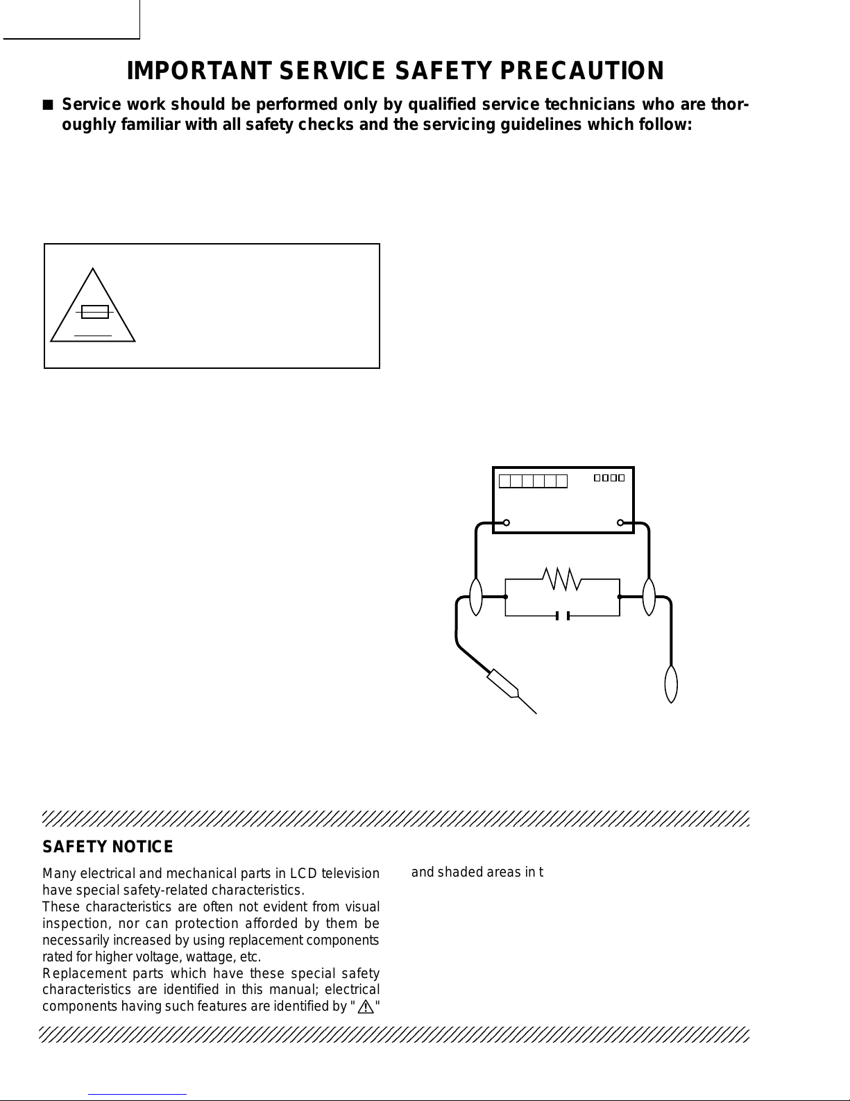
3. To be sure that no shock hazard exists, check for
leakage current in the following manner.
• Plug the AC cord directly into a 110~240 volt AC outlet,
and connect the DC power cable into the receiver's DC
jack. (Do not use an isolation transformer for this test).
• Using two clip leads, connect a 1.5k ohm, 10 watt
resistor paralleled by a 0.15µF capacitor in series with
all exposed metal cabinet parts and a known earth
ground, such as electrical conduit or electrical ground
connected to an earth ground.
• Use an AC voltmeter having with 5000 ohm per volt, or
higher, sensitivity or measure the AC voltage drop
across the resistor.
• Connect the resistor connection to all exposed metal
parts having a return to the chassis (antenna, metal
cabinet, screw heads, knobs and control shafts,
escutcheon, etc.) and measure the AC voltage drop
across the resistor.
All checks must be repeated with the AC cord plug
connection reversed. (If necessary, a nonpolarized
adaptor plug must be used only for the purpose of
completing these checks.)
Any reading of 0.75V peak (this corresponds to 0.5 mA.
peak AC.) or more is excessive and indicates a potential
shock hazard which must be corrected before returning
the monitor to the owner.
A V
DVM
AC SCALE
1.5k ohm
10W
TO EXPOSED
METAL PARTS
CONNECT TO
KNOWN EARTH
GROUND
0.15 µF
TEST PROBE
3
LC-13B6U-S
LC-15B6U-S
PRECAUTION: POUR LA
PROTECTION CONTINUE
CONTRE LES RISQUES
D'INCENDIE, REMPLACER LE
FUSIBLE P AR UN FUSIBLE DE
MEME TYPE F3701 (2.0A, 250V),
F3702 (1.25A, 250V), F6501 (1.25A,
250V), F6502 (1.25A, 250V).
234567890123456789012345678901212345678901234567890123456789012123456789012345678901234567890121
2
234567890123456789012345678901212345678901234567890123456789012123456789012345678901234567890121
2
234567890123456789012345678901212345678901234567890123456789012123456789012345678901234567890121
2
AVIS POUR LA SECURITE
De nombreuses pièces, électriques et mécaniques, dans
les téléviseurs présentent des caractéristiques spéciales
relatives à la sécurité, qui ne sont souvent pas évidentes
à vue. Le degré de protection ne peut pas être
nécessairement augmentée en utilisant des pièces de
remplacement étalonnées pour haute tension,
puissance, etc.
Les pièces de remplacement qui présentent ces
caractéristiques sont identifiées dans ce manuel; les
pièces électriques qui présentent ces particularités sont
PRECAUTIONS A PRENDRE LORS DE LA REPARATION
Ë
Ne peut effectuer la réparation qu' un technicien spécialisé qui s'est parfaitement
accoutumé à toute vérification de sécurité et aux conseils suivants.
identifiées par la marque " å " et hachurées dans la
liste des pièces de remplacement et les diagrammes
schématiques.
Pour assurer la protection, ces pièces doivent être
identiques à celles utilisées dans le circuit d'origine.
L'utilisation de pièces qui n'ont pas les mêmes
caractéristiques que les pièces recommandées par
l'usine, indiquées dans ce manuel, peut provoquer des
électrocutions, incendies, radiations X ou autres
accidents.
AVERTISSEMENT
1. N'entreprendre aucune modification de tout circuit.
C'est dangereux.
2. Débrancher le récepteur avant toute réparation.
VERIFICA TIONS CONTRE L'INCEN-DIE ET
LE CHOC ELECTRIQUE
Avant de rendre le récepteur à l'utilisateur, effectuer
les vérifications suivantes.
1. Inspecter tous les faisceaux de câbles pour s'assurer
que les fils ne soient pas pincés ou qu'un outil ne soit
pas placé entre le châssis et les autres pièces
métalliques du récepteur.
2. Inspecter tous les dispositifs de protection comme les
boutons de commande non-métalliques, les isolants,
le dos du coffret, les couvercles ou blindages de réglage
et de compartiment, les réseaux de résistance-capacité,
les isolateurs mécaniques, etc.
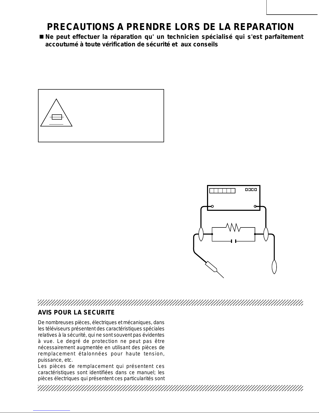
3. S'assurer qu'il n'y ait pas de danger d'électrocution en
vérifiant la fuite de courant, de la facon suivante:
• Brancher le cordon d'alimentation directem-ent à une
prise de courant de 110-240V. (Ne pas utiliser de
transformateur d'isolation pour cet essai).
• A l'aide de deux fils à pinces, brancher une résistance
de 1.5kΩ 10 watts en parallèle avec un condensateur
de 0.15µF en série avec toutes les pièces métalliques
exposées du coffret et une terre connue comme une
conduite électrique ou une prise de terre branchée à la
terre.
• Utiliser un voltmètre CA d'une sensibilité d'au moins
5000Ω/V pour mesurer la chute de tension en travers
de la résistance.
• Toucher avec la sonde d'essai les pièces métalliques
exposées qui présentent une voie de retour au châssis
(antenne, coffret métallique, tête des vis, arbres de
commande et des boutons, écusson, etc.) et mesurer
la chute de tension CA en-travers de la résistance.
T outes les vérifications doivent être refaites après avoir
inversé la fiche du cordon d'alimentation. (Si nécessaire,
une prise d'adpatation non polarisée peut être utilisée
dans le but de terminer ces vérifications.)
Tous les courants mesurés ne doivent pas dépasser
0,5 mA.
Dans le cas contraire, il y a une possibilité de choc
électrique qui doit être supprimée avant de rendre le
récepteur au client.
A V
DVM
ECHELLE CA
1.5k ohm
10W
0.15 µF
SONDE D'ESSAI
AUX PIECES
METALLIQUES
EXPOSEES
BRANCHER A UNE
TERRE CONNUE
4
LC-13B6U-S
LC-15B6U-S
Precautions for using lead-free solder
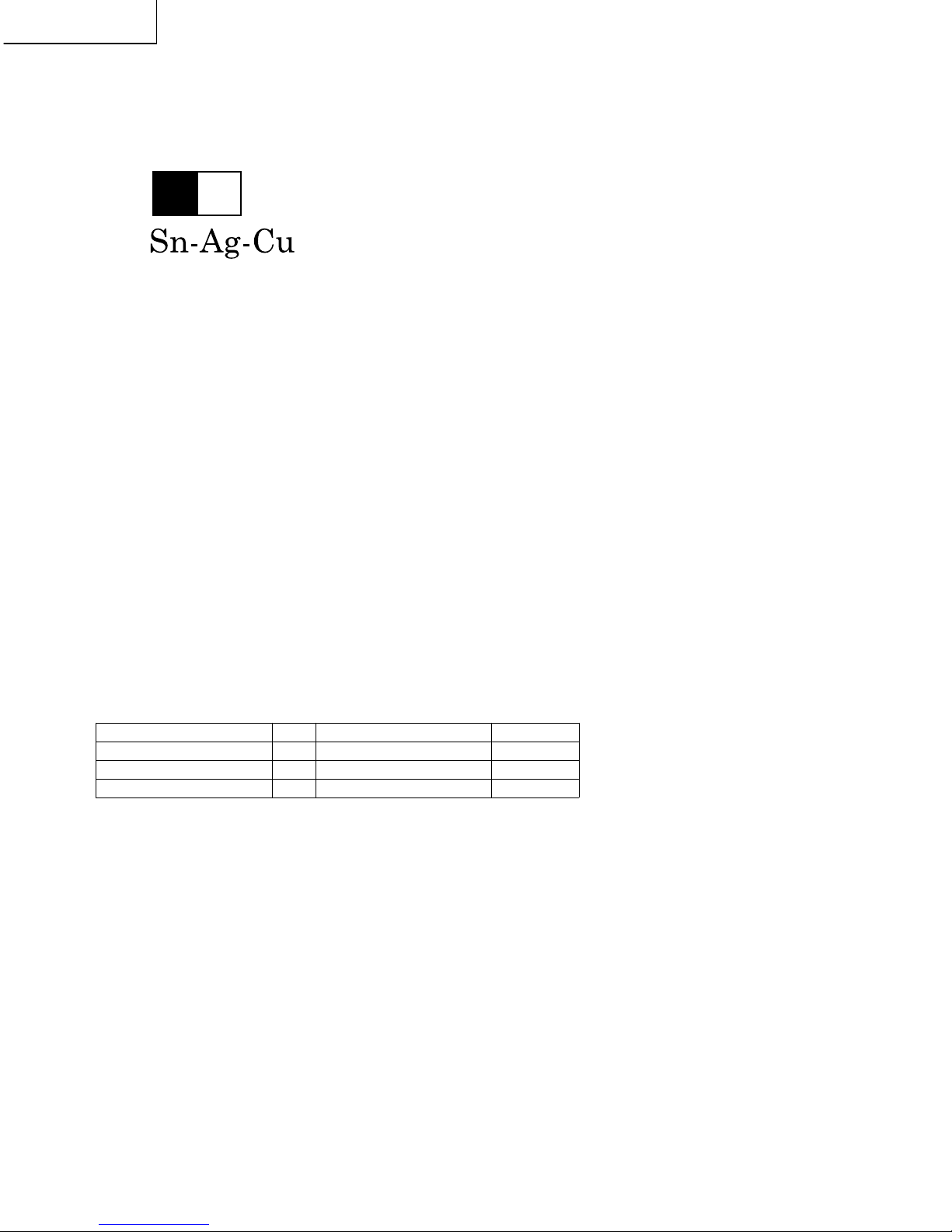
1 Employing lead-free solder
"All PWBs" of this model employs lead-free solder. The LF symbol indicates lead-free solder, and is attached on
the PWBs and service manuals. The alphabetical character following LF shows the type of lead-free solder.
Example:
2 Using lead-free wire solder
When fixing the PWB soldered with the lead-free solder, apply lead-free wire solder. Repairing with conventional
lead wire solder may cause damage or accident due to cracks.
As the melting point of lead-free solder (Sn-Ag-Cu) is higher than the lead wire solder by 40°C, we recommend
you to use a dedicated soldering bit, if you are not familiar with how to obtain lead-free wire solder or soldering bit,
contact our service station or service branch in your area.
3 Soldering
As the melting point of lead-free solder (Sn-Ag-Cu) is about 220°C which is higher than the conventional lead
solder by 40°C, and as it has poor solder wettability, you may be apt to keep the soldering bit in contact with the
PWB for extended period of time. However, Since the land may be peeled off or the maximum heat-resistance
temperature of parts may be exceeded, remove the bit from the PWB as soon as you confirm the steady soldering
condition.
Lead-free solder contains more tin, and the end of the soldering bit may be easily corroded. Make sure to turn on
and off the power of the bit as required.
If a different type of solder stays on the tip of the soldering bit, it is alloyed with lead-free solder . Clean the bit after
every use of it.
When the tip of the soldering bit is blackened during use, file it with steel wool or fine sandpaper.
Be careful when replacing parts with polarity indication on the PWB silk.
Indicates lead-free solder of tin, silver and copper.
Lead-free wire solder for servicing
Part No, ★ Description Code
ZHNDAi123250E J φ0.3mm 250g(1roll) BL
ZHNDAi126500E J φ0.6mm 500g(1roll) BK
ZHNDAi12801KE J φ1.0mm 1kg(1roll) BM
L Fa
5
LC-13B6U-S
LC-15B6U-S
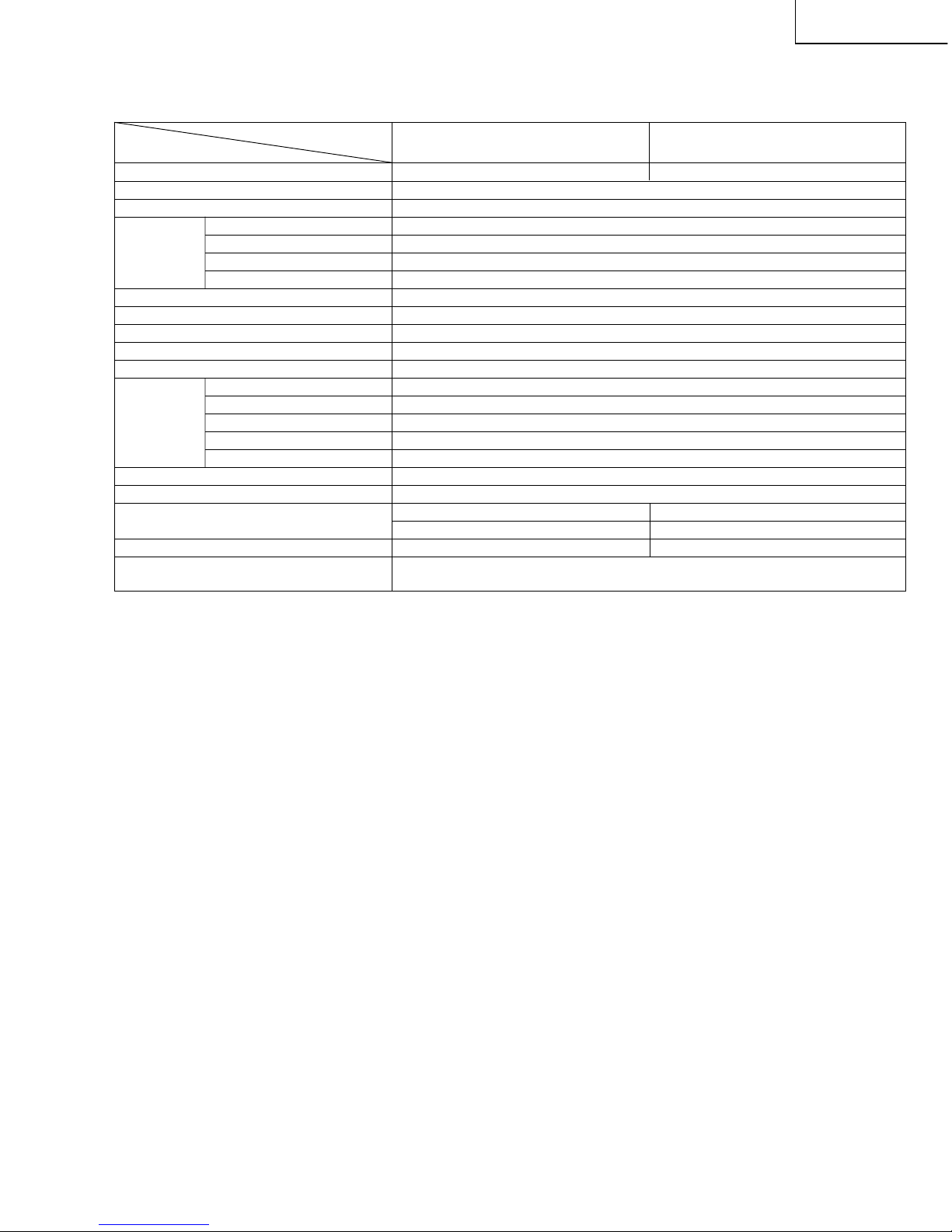
SPECIFICATIONS
Items
LCD panel
13"Advanced Super View & BLACK TFT LCD 15"Advanced Super View & BLACK TFT LCD
Number of dots 921,600 dots VGA
Video color systems N358, N443, PAL, PAL-M, PAL-N, SECAM, PAL-60
TV Standard (CCIR) NTSC/PAL-M/PAL-N
TV function
TV Tuning System PLL 181 ch.
STEREO MTS+SAP
CATV 125 ch.
Y/C FILTER 3D Y/C FILTER
Brightness 430 cd/m
2
Viewing angles H: 170° V: 170°
Audio amplifier 2.1 W × 2
Speakers 1 37/64× 23/4in. (4 × 7cm), 2 pcs.
AV-IN1 AV-IN1, S-VIDEO-IN
AV-IN2 AV-IN2/AV-OUT
Terminals COMPONENT COMPONENT-IN, AUDIO-IN
Antenna F-Type
Headphone Mini-jack for stereo (ø3.5 mm)
OSD language English/Spanish/French
Power supply DC 12V, AC 110-240V, 50/60Hz (AC adapter), AC 110-125V (AC cord)
Power consumption 37 W (0.5 W standby): AC 120V 40 W (0.5 W standby): AC 120V
31 W: DC 12V 34 W: DC 12V
Weight 9.7 lbs. (4.4 kg), w/o accessories 11.5 lbs. (5.2 kg), w/o accessories
Accessories Remote control, Batteries ( 2), Antenna cable, AC adapter, AC cord, Cable clamps ( 2),
Operation manual
■As a part of policy of continuous improvement, SHARP reserves the right to make design and specification changes for product improvement without prior notice. The performance specification figures indicated are nominal values of production units. There may be some
deviations from these values in individual units.
Model
LC-13B6U
LC-15B6U
××
6
LC-13B6U-S
LC-15B6U-S
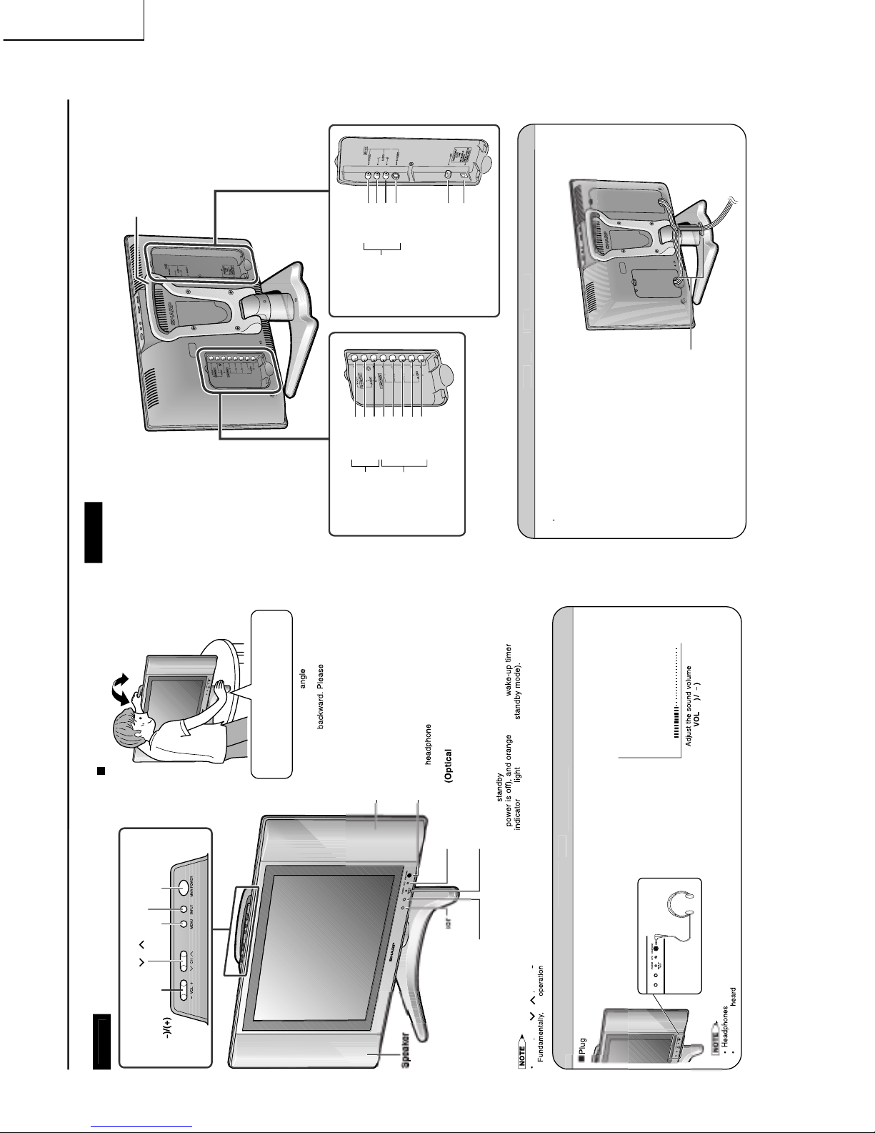
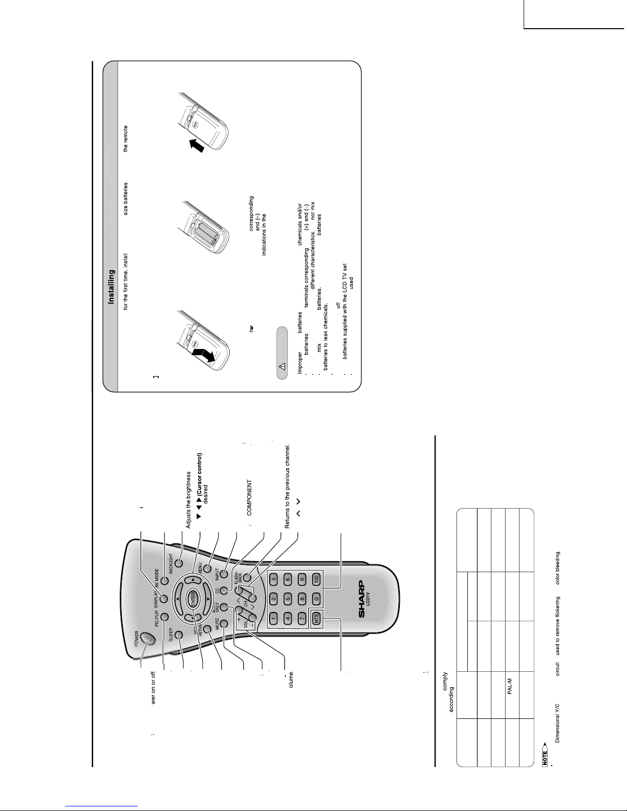
OPERATION MANUAL
–
jack
–
Tilt the display by grabbing onto the
carrying handle while securely holding
jack
jack.
–
Terminals
Carrying handle
Rear View
Y
P
B
P
R
AUDIO (L)
AUDIO (R)
VIDEO
AUDIO (R)
AUDIO (L)
AV-IN2/OUT
ANT. (Antenna terminal)
POWER INPUT
(DC 12V)
AV-IN1
COMPONENT
VIDEO
AUDIO (L)
AUDIO (R)
S-VIDEO
Cable clamps (×
×
2)
7
LC-13B6U-S
LC-15B6U-S
Y
MODE
MODE.
/
/
/
V1,
V2,
ele
our
Y
–
–
+
–
+
–
8
LC-13B6U-S
LC-15B6U-S
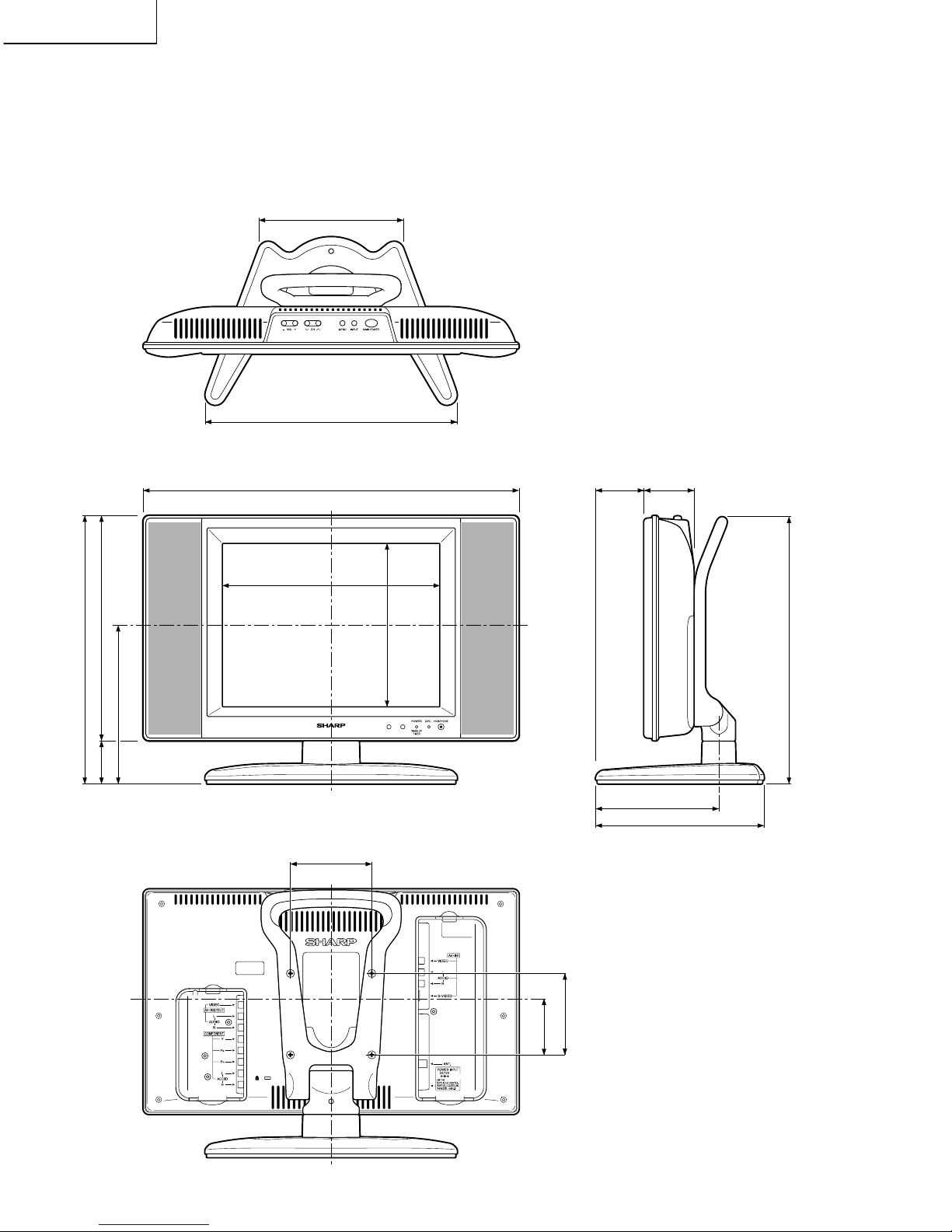
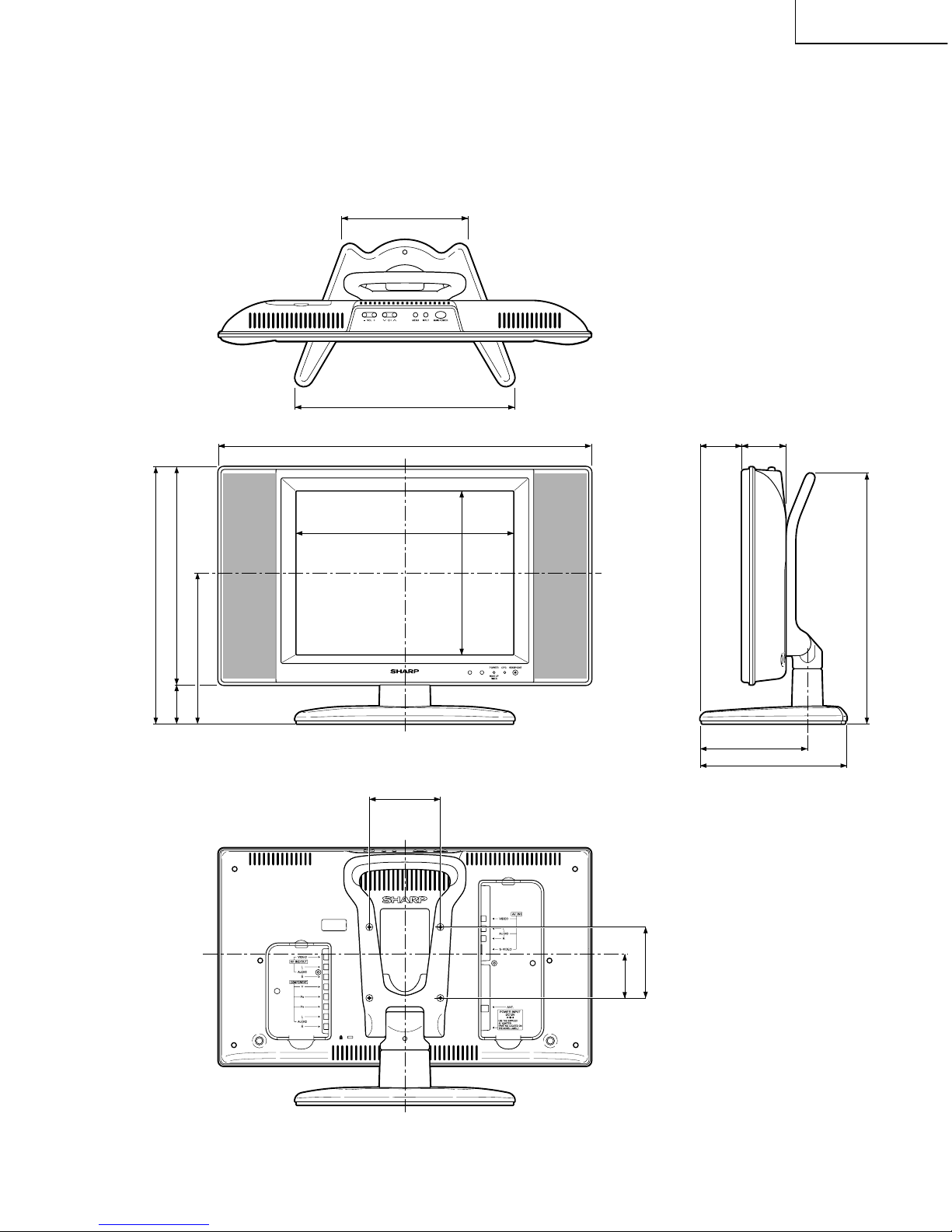
DIMENSIONS
ËLC-13B6U-S
Unit: inch (mm)
12
7
/
32
(310)
7
1
/
64
(178)
10
33
/
64
(267)
7
23
/
32
(196)
13
3
/
64
(331) (including rubber foot)
18
13
/
64
(462)
10
29
/
32
(277)
2
9
/
64
(54)
2
29
/
64
(62)2
3
/
8
(60)
8
5
/
32
(207)
5
61
/
64
(151)
12 (330) (including rubber foot)
2
23
/
32
(69)
3
15
/
16
(100)
3
15
/
16
(100)
7
29
/
32
(200.8)
9
LC-13B6U-S
LC-15B6U-S
ËLC-15B6U-S
Unit: inch (mm)
12
7
/
32
(310)
7
1
/
64
(178)
12
3
/
32
(307)
9
7
/
64
(231)
8
25
/
64
(213)
14
19
/
64
(363) (including rubber foot)
20
23
/
32
(526)
12
3
/
32
(307)
2
7
/
32
(56)
2
29
/
64
(62)2
21
/
64
(59)
8
5
/
32
(207)
5
61
/
64
(151)
13
15
/
16
(354) (including rubber foot)
2
29
/
64
(62)
3
15
/
16
(100)
3
15
/
16
(100)
10
LC-13B6U-S
LC-15B6U-S
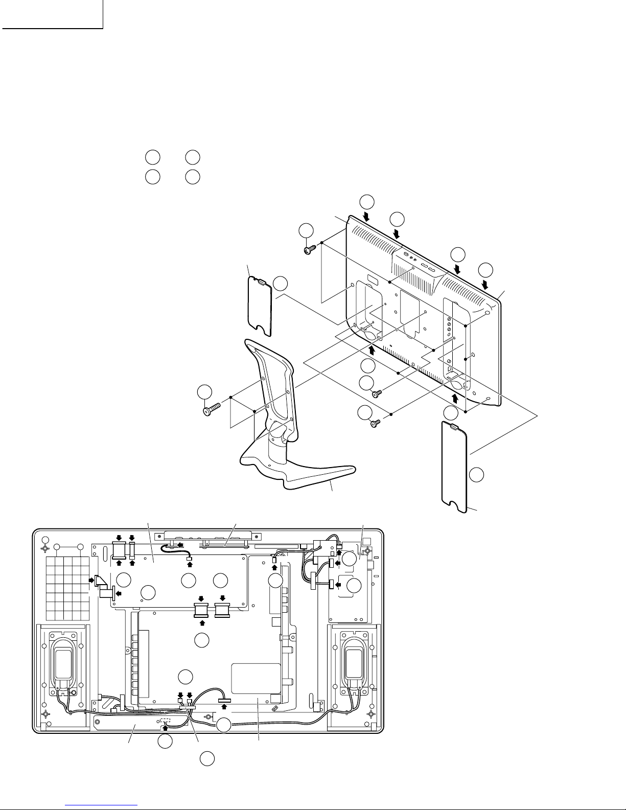
REMOVING OF MAJOR PARTS
1. Remove the four lock screws from the stand, and detach the stand.
2. Remove the terminal covers (long and short).
3. Remove the four terminal screws. (LC-13B6U-S)
3. Remove the two terminal screws. (LC-15B6U-S)
4. Remove the eight lock screws from the cabinet B.
5. Cabinet A is order of
5-4
thru
5-5
, and detach the cabinet B. (LC-13B6U-S)
5. Cabinet A is order of
5-1
thru
5-6
, and detach the cabinet B. (LC-15B6U-S)
6. Remove the wire holder, and disconnect the connecting cable.
7. Disconnect all the connectors from all the PWBs.
Cabinet B
4
3
3
1
2
2
5-2
Cabinet A
Terminal Cover (S)
Terminal Cover (L)
Only for LC-13B6U-S
Stand
5-6
5-5
5-4
5-3
5-1
P3701
P4001
P4050
P3302
SC2001
P2003
SC3403
SC701
P3704
P3404
P6500
P6501
P6502
P3702
SC1201
SC1202
SC1203
CN2
CN1
CN3
Operation PWB
Main PWB
R/C, LED PWB
Inverter PWB
7
7 7 7
7
7
7
7
7
7
7
6
Analog PWB
Wire Holder
11
LC-13B6U-S
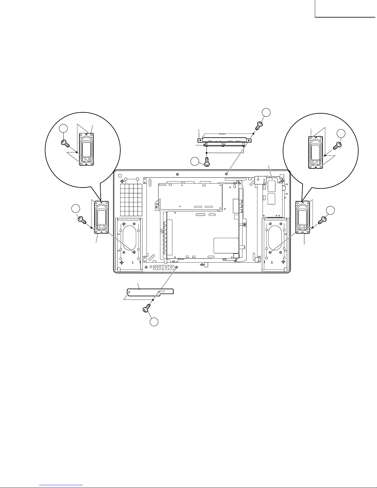
LC-15B6U-S
7. Remove the two lock screws from the operation panel (top cover), and detach the operation panel (top cover).
8. Remove the two lock screws from the operation PWB, and detach the operation PWB.
9. Remove the two lock screws from the R/C, LED PWB, and detach the R/C, LED PWB.
10. Remove the three lock screws each from the speakers (left and right), and detach both the speakers.
Speaker (R)
R/C, LED PWB
Analog PWB
Main PWB
Speaker (L)
Inverter PWB
Operation panel (Top Cover)
Operation PWB
10
8
7
10
9
Only for
LC-13B6U-S
Speaker (L)
10
Only for
LC-13B6U-S
Only for
LC-15B6U-S
Only for
LC-15B6U-S
Speaker (R)
10
12
LC-13B6U-S
LC-15B6U-S
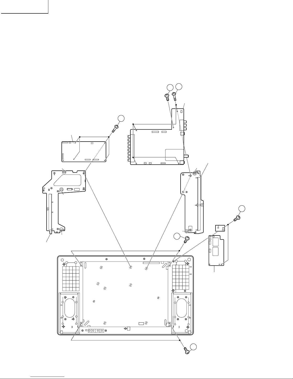
11. Remove the two lock screws from the inverter PWB, and detach the inverter PWB.
12. Remove the four lock screws from the main PWB, and undo the claws a. Detach the main PWB by lifting the area
around the claws and pulling the PWB out.
13. Remove the five lock screws from the analog PWB, and undo the claws b and c. Detach the chassis frame (right)
from the analog PWB by pulling out the terminals. In the same way, undo the claws d and e, and detach the
chassis frame (left) from the analog PWB by pulling out the terminals.
Note: When detaching the main PWB and analog PWB, be careful not to break the PWB-fixing claws.
14. Remove the tow lock screws from the LCD panel unit, and detach the LCD panel unit. (LC-13B6U-S)
14. Remove the four lock screws from the LCD panel unit, and detach the LCD panel unit. (LC-15B6U-S)
Inverter PWB
Chassis Frame (L)
Main PWB
Analog PWB
e
LCD Panel Unit
12
13
13
11
14
14
a
d
b
c
Chassis Frame (R)
Only for LC-15B6U-S

13
LC-13B6U-S
LC-15B6U-S
» Precautions in handling the LCD panels
1. Work in a clean room (with humidities below 50%).
2. Be sure to wear an anti-static armband.
3. Handle the panels on an electro-conductive mat.
4. Be careful not to fall, shake and shock the panels.
15. Remove the four lock screws from the LCD panel unit.
16. Detach the diffusion sheet, prism sheet and reflection/deflection sheet.
17. Detach the four reflection mirrors.
18. Detach the two reflection sheets (Cover).
19. Remove the lamp unit.
20. Detach the Light guide plate.
21. Detach the two reflection sheets-1, -2.
Reflection Sheet (Cover)
(PSHEP0306CEZZ:LC-13B6U-S)
(PSHEP0307CEZZ:LC-15B6U-S)
Lamp unit
(KLMP-A037WJZZ:LC-13B6U-S)
(KLMP-A045WJZZ:LC-15B6U-S)
Back Shield
(PSLDMA314WJFW:LC-13B6U-S)
(PSLDMA566WJFW:LC-15B6U-S)
Reflection Sheet-2
(PSHEP0280CEZZ:LC-13B6U-S)
(PSHEP0285CEZZ:LC-15B6U-S)
Reflection Sheet-1
(PSHEP0279CEZZ:LC-13B6U-S)
(PSHEP0284CEZZ:LC-15B6U-S)
Light Guide Plate
(PGiDMA010WJZZ:LC-13B6U-S)
(PGiDMA011WJZZ:LC-15B6U-S)
Reflection/deflection Sheet
(PSHEP0276CEZZ:LC-13B6U-S)
(PSHEP0281CEZZ:LC-15B6U-S)
Diffusion Sheet
(PSHEP0278CEZZ:LC-13B6U-S)
(PSHEP0283CEZZ:LC-15B6U-S)
Prism Sheet
(PSHEPA143WJZZ:LC-13B6U-S)
(PSHEPA141WJZZ:LC-15B6U-S)
LCD Panel Unit
19
15
16
20
21
17
17
18
Reflection Mirror
Reflection Mirror
14
LC-13B6U-S
LC-15B6U-S
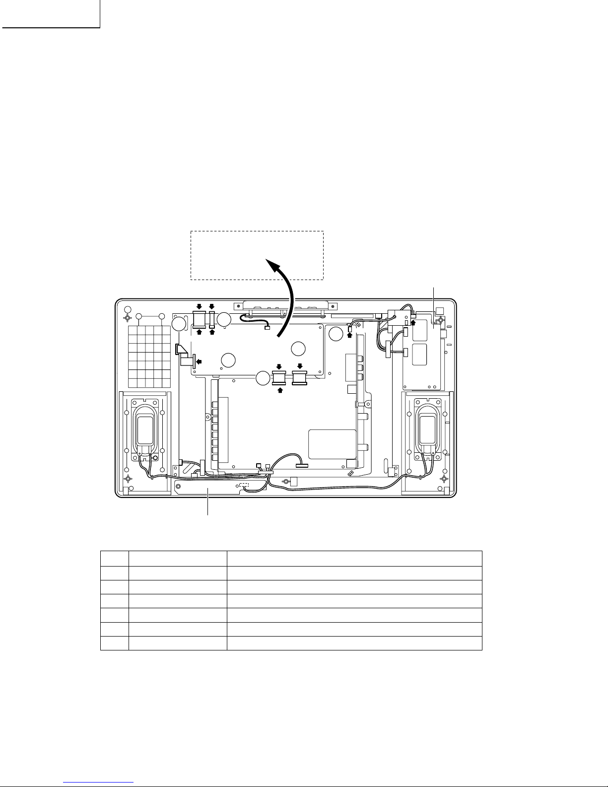
Step Part No. Description
1 QCNW-A556WJZZ Extension Cable 50-pin Main (SC1202)-LCD panel
2 QCNW-A555WJZZ Extension Cable 20-pin Main (SC1201)-LCD panel
3 QCNW-B784WJZZ Extension Cable 30-pin Main (SC1203)-LCD panel
4 QCNW-C461WJQZ Extension Cable 15-pin Main (SC701)-Analog (P3704)
5 QCNW-C459WJQZ Extension Cable 60-pin Main (SC2001)-Analog (SC3403)
6 QCNW-A551WJZZ Extension Cable 3-pin Analog (P3702)-Inverter (P6502)
» Precautions in servicing Side B (back) of the main PWB unit
1. Disconnect the FFC (flat cable) from between the main PWB (SC1202) and LCD panel. Connect the servicespecific extension FFC (flat cable) (QCNW-A556WJZZ) instead.
2. Disconnect the FFC (flat cable) from between the main PWB (SC1201) and LCD panel. Connect the servicespecific extension FFC (flat cable) (QCNW-A555WJZZ) instead.
3. Disconnect the FFC (flat cable) from between the main PWB (SC1203) and LCD panel. Connect the servicespecific extension FFC (flat cable) (QCNW-B784WJZZ) instead.
4. Disconnect the SC701 side of the lead from between the main PWB (SC701) and the analog PWB (P3704), and
then connect the service-specific extension cable (QCNW-C461WJQZ).
5. Disconnect the FFC from between the main PWB (SC2001) and the analog PWB (SC3403), and then connect
the service-specific extension FFC (flat cable) (QCNW-C459WJQZ).
6. Disconnect the P3702 side of the lead from between the analog PWB (P3702) and the inverter PWB (P6502),
and then connect the service-specific extension cable (QCNW-A551WJZZ).
7. Remove the four lock screws from the main PWB. Detach this PWB from the chassis frame and turn it over.
SC2001
SC3403
SC701
P3702
P6502
P3704
SC1201
SC1202
CN2 CN3
SC1203
Main PWB
(Side-B)
Inverter PWB
R/C, LED PWB
3
1
2
4
6
5
Analog PWB
Main PWB

15
LC-13B6U-S
LC-15B6U-S
ADJUSTING PROCEDURE OF EACH SECTION
1. Pre-adjustment preparations
Use the specific AC adaptor or a stable DC power supply as power source.
LC-13/15B6U-S AC adapter: UADP-A044WJPZ
DC power supply: 12 (V), 5.4 (A) or more
1. How to enter the adjustment process mode
The following two methods are available.
» While holding down the "INPUT" and "VOL (–)" keys on the set, turn ON the power and press the "CH (Ù)" and
"VOL (–)" keys at once.
» Turn ON the power with either of KEY4 (pin (81) of microprocessor) and KEY5 (pin (82) of microprocessor)
staying at "L".
2. Key operation in adjustment process
Ë Basic operation
» Select a station with the "CH (ù)/(Ù)" key.
» Switch the input with the "INPUT" key.
» Using the "cursor UP/DOWN" key, select an item to be adjusted. (When the "cursor DOWN" key is pressed with
the cursor placed on the bottom item, the cursor will move to the top item on the next page. When the "cursor
UP" key is pressed with the cursor placed on the top item, the cursor will move to the bottom item on the previous
page.)
» Adjust the selected item with the "VOL (+)/(–)" key or the cursor "RIGHT/LEFT" key
» Pressing the "MENU" key will move the cursor to the next item. (When the "MENU" key is pressed with the cursor
placed on the bottom item, the cursor will move to the top item on the next page.)
» Pressing the "manual memory" key will return the cursor to the top item. (When the "manual memory" key is
pressed with the cursor placed on the top item, the cursor will move to the top item on the previous page.)
» Pressing the "auto preset" key will move the cursor to the top item on the next page.
Ë Hierarchical structure
» When the "ENTER" key is pressed with the cursor placed on an item other than I
2
C DATA on page 9, the setting
page corresponding to the selected item will appear.
» To exit each setting page, press the "FLASHBACK" key.
Initialization
1. Set both pins (81) and (82) of IC2001 (microprocessor) to GND and turn ON the power
2. Check the model name (A626). *Note: MODEL cannot be changed.
3. Inch size selection
Check INCH SIZE (13/15)
2. Adjustment Procedures
1. AD converter level adjustment
1 D3 input
1) D3 75% color bar signal input
Device name: LEADER LT446
Signal name: COLOR BAR 75%
Setting: 01: 1920 x 1080 / 60i
H: 33.72kHz, V: 29.97Hz
2) Set AUTO GAIN-OFFSET1 on page 7 of the adjustment process menu to ON.
3. Common bias adjustment
1. Receive a B/W broadcast channel.
2. Adjust the "COM BIAS" setting on adjustment process page 2 so that the contrast
goes to maximum (black most accentuated).
16
LC-13B6U-S
LC-15B6U-S
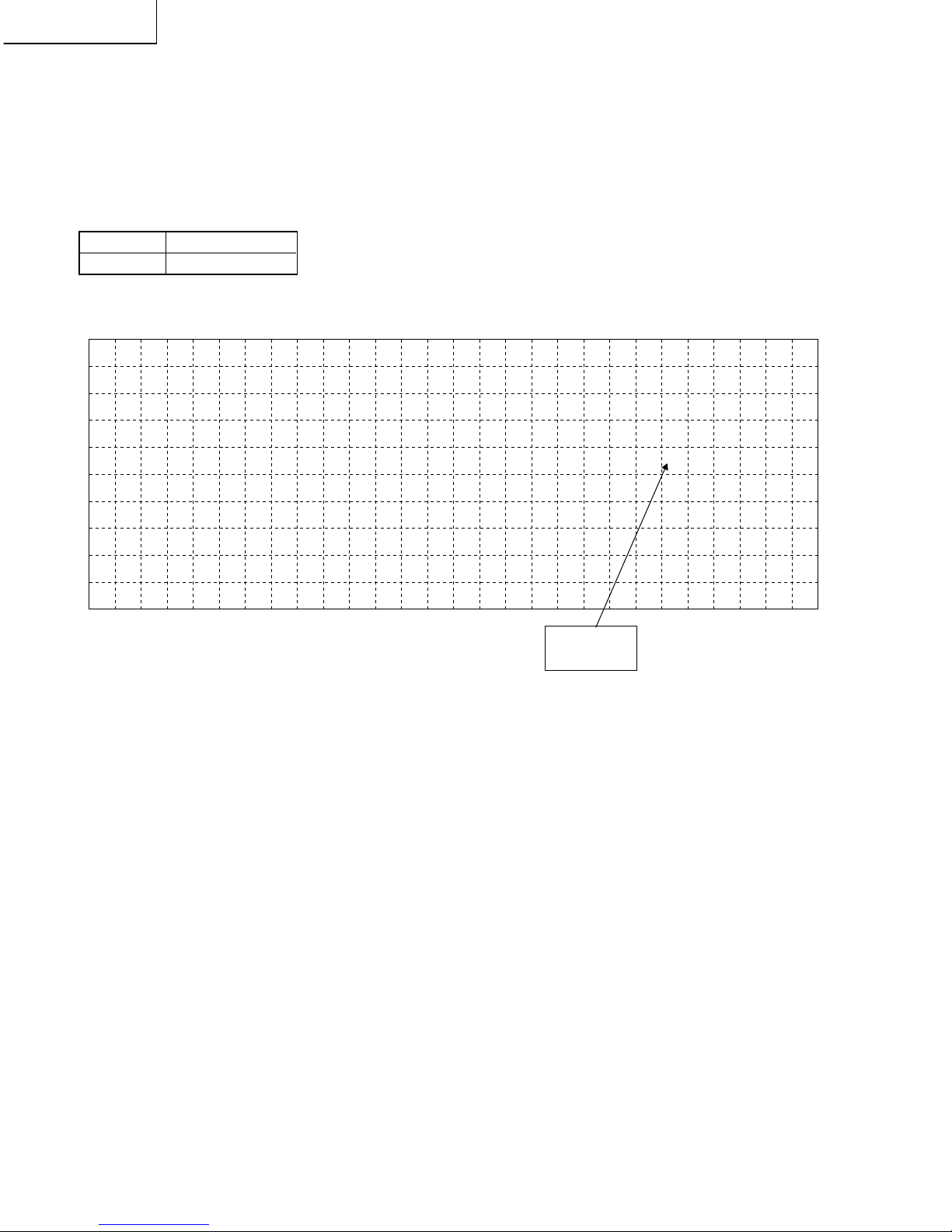
4. Adjustment of TAMP
1. 75% standard color bar signal reception
2. If the reading of "YDATA" on page 2 of the adjustment process menu falls outside the range shown in the table below,
adjust "NTSC TAMP" on this page so that the reading of "YDATA" falls within this range.
* Note that settings may vary with models.
3. Set "PAL-M TAMP" and "PAL-N TAMP" to the same value to which "NTSC TAMP" is set.
Reference
(Page 2 of adjustment process menu)
Model LC-13/15B6U-S
Setting 157-160
0212
C
T
Y
T
N
P
P
3
O
A
D
A
T
A
A
4
M
M
A
M
S
L
L
5
P
T
P
C
-
-
6
B
A
M
N
7
I
L
H
T
8
A
A
T
T
9
S
M
A
A
10
P
M
M
11
P
P
12 13 14 15 16 17 18 19 20 21
1
1
1
1
22
2
5
5
6
7
7
7
23
0
7
9
0
0
0
0
24 25 26
0
1
2
3
4
5
6
7
8
Y Data
(White 75%)
17
LC-13B6U-S
LC-15B6U-S
5. Adjustment of white balance
1. How to adjust the white balance
1 Select the component -480i input.
2 Adjust "R CUTOFF2" and "B CUTOFF2" so that "White 30%" takes on the following WB target values.
Caution: "G CUTOFF2" should be fixed.
3 Adjust two strong colors of "R/G/B-GAIN" downward so that "White 80%" takes on the WB target values.
Caution: Any one of "R/G/B-GAIN" should be fixed at 64.
4 Repeat steps 2 and 3 so that "White 30%" and "White 80%" takes on the target values.
5 Enter the values of "R/B_CUTOFF2" and "R/G/B-GAIN" set in steps 2 to 4 in the corresponding items of
"Composite adjustment", "Component -1080i adjustment" and "PC-VGA adjustment" shown below.
6 Select the composite input and check that "White 30%" and "White 80%" are within the inspection specifications
on the next page.
Caution: The component Ys output signal of the automatic regulator should be used also when the composite
input is selected. In the case of the CVBS output, the signal level is different.
7 If "White 30%" and "White 80%" are not within the inspection specifications, make the adjustment described in
steps 2 to 4.
8 Select the component -1080i input and check that "White 30%" and "White 80%" are within the inspection
specifications on the next page.
9 If "White 30%" and "White 80%" are not within the inspection specifications, make the adjustment described in
steps 2 to 4.
0 Select the PC-VGA input and check that "White 30%" and "White 80%" are within the inspection specifications
on the next page.
q If "White 30%" and "White 80%" are not within the inspection specifications, make the adjustment described in
steps 2 to 4.
2. Adjustment value
• Composite adjustment...RGB CUTOFF2 and RGB-GAIN on page 3 of adjustment process menu
• Component -480i adjustment...A RGB CUTOFF2 and A RGB-GAIN on page 4 of adjustment process menu
• Component -1080i adjustment...D RGB CUTOFF2 and D RGB-GAIN on page 5 of adjustment process menu
3. WB target value (numeric values for MINOLTA CA-210)
Adjustment value Adjustment specifications
White 80% x=0.291 ±0.006
y=0.300 ±0.006
White 30% x=0.276 ±0.006
y=0.282 ±0.006
Remarks The numeric values shown above are for MINOLTA CA-210.
(Reference) White 80%...luminance: 250 cd/m2, About 8500K
White 30%...luminance: 25 cd/m2, About 11000K
4. WB adjustment range
R/G/B CUTOFF2: –20 to +20 (G CUTOFF2 fixed at 0)
R/G/B GAIN: 36 to 64 (One of the colors fixed at 64)
18
LC-13B6U-S
LC-15B6U-S
6.Factory setting
1. Factory adjustment procedure
While holding down the "INPUT" and "VOL (–)" keys on the set, turn ON the power and press the "CH (ù)" and "VOL
(+)" keys at once.
2. DESCRIPTION OF FACTORY SETTINGS
ITEM SETTING
OTHER THAN MENU
STARTUP OF EZ SETUP AT POWER-ON ON
SELECT LANGUAGE ENGLISH
CH-SETTING ON
AUTO CLOCK ON
LAST CHANNEL 2ch
LAST TV/INPUT TV
FLASH BACK 2ch
VOLUME 20
MENU-PICTURE
AV MODE DYNAMIC
OPC OFF
BACKLIGHT BRIGHT (17)
CONTRAST 56
BRIGHTNESS 0
COLOR +2
TINT 0
SHARPNESS +4
ADVANCED COLOR TEMP. MIDDLE
RED 0
GREEN 0
BLUE 0
I/P SETTING PROGRESSIVE
NOISE CLEAN OFF
FILM MODE OFF
MENU-AUDIO
TREBLE 0
BASS 0
BALANCE 0
WIDE SOUND OFF
SPEECH EMPHASIS OFF
FOR STANDARD
FOR MOVIE FOR GAME
OFF OFF OFF
BRIGHT (17) BRIGHT (17) NORMAL(9)
50 50 50
000
0+20
000
000
19
LC-13B6U-S
LC-15B6U-S
MENU-SETUP
CH-SETTING AIR/CABLE AIR
CH MEMORY SKIP ALL CH ON
MTS STEREO
CLOCK SET AUTO EDS CH AUTO
MENU DST OFF
TIME 12:00AM
TIME DISPLAY ON
AV2 IN/OUT IN
V-CHIP BLOCK INPUT SECRET NO. CLEAR
MPAA G, PG, PG-13, R, NC-17, X ALL CLEAR
TV GUIDELINES TV-Y, TV-Y7, TV-G, TV-PG, TV-14, TV-MA ALL CLEAR
BLOCK CONTENT D, L, S, V, FV ALL CLEAR
CAN. ENGLISH RATINGS C, C8+, G, PG, 14+, 18+ ALL CLEAR
CAN. FRENCH RATINGS G, 8 ans+, 13 ans+, 16 ans+, 18 ans+ ALL CLEAR
STATUS OFF
CLOSED CAPTION OFF
COLOR SYSTEM (FOR TV) N358
COLOR SYSTEM (FOR AV 1 AND 2) AUTO
LANGUAGE ENGLISH
MENU-OPTION
VIEW MODE 4 : 3
AUDIO ONLY OFF
SLEEP TIMER OFF
WAKEUP TIMER TIMER OFF
TIME 12:00AM
CHANNEL 2
VOLUME 20
NO SIGNAL OFF DISABLE
NO OPERATION OFF DISABLE
PICTURE FLIP NORMAL
20
LC-13B6U-S
LC-15B6U-S
PUBLIC MODE SETTING PROCEDURE
1. How to start Public Mode
» There are the following two ways to get the public mode setup screen displayed.
1 In the adjustment process mode, turn on "PUBLIC MODE". Also press the "CH (ù)" and "VOL (+)" keys on
the set at once and turn on the power.
2 1) Press the "INPUT" and "VOL (+)" keys on the set at once and turn on the power.
2) Get the password input screen displayed.
Procedure
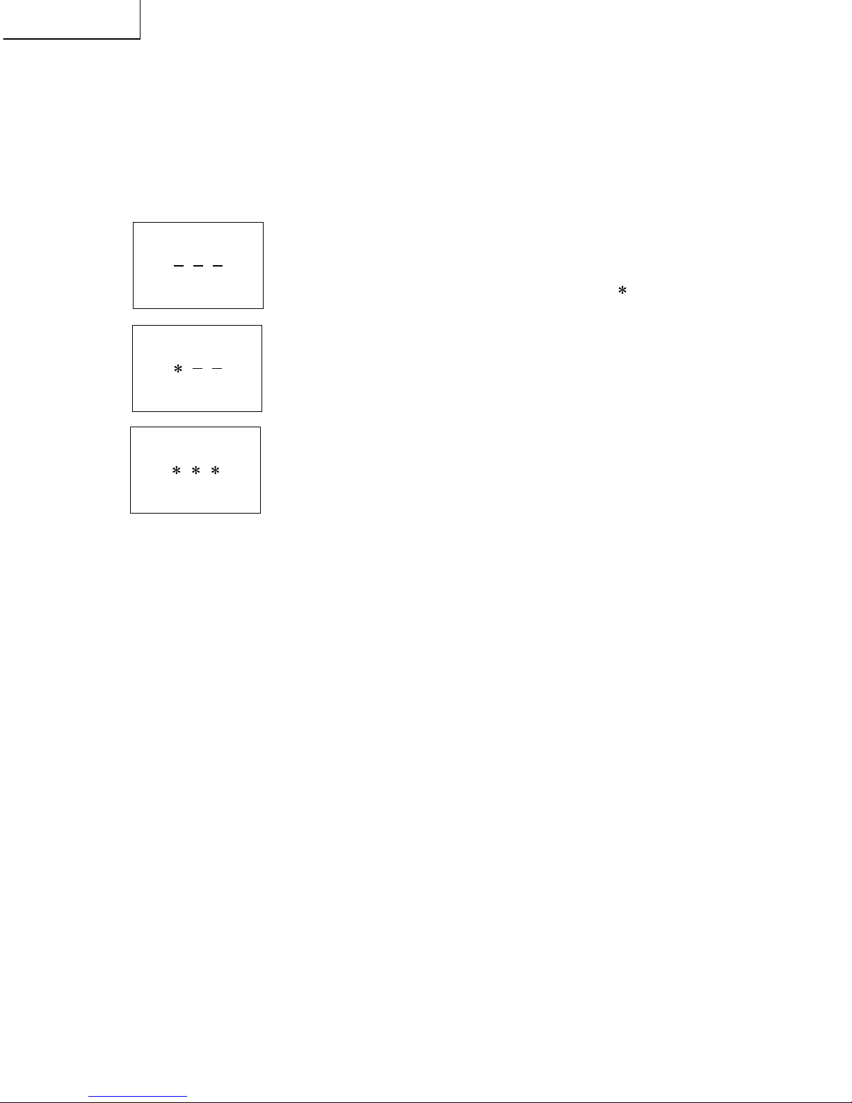
» The input starts with the leftmost digit.
» Use the numeric keys [1] thru [9] and [10/0] keys on the remote con-
troller. The other keys are not acceptable.
» With a numeric-key input, "–" will change to " ". The input position
will move one digit to the right.
» With all the 3 digits entered, the password will be verified.
3) The 3-digit password is now verified.
The password [0] [2] [7] provides for the public mode screen. (This screen comes on with whatever
adjustment process settings.)
With any other passwords, the screen changes to the normal mode.

21
LC-13B6U-S
LC-15B6U-S
2. How to exit Public Mode
There are the following ways to quit the public mode setup screen.
» Turn off "PUBLIC MODE" in the adjustment process mode. (✩) ← This way alone is not for quitting the setup
screen, but for quitting the mode itself.
» Turn off the power with the "POWER" key. (★)
» Select "ENTER". (★)
» Move the cursor to "RESET" and press the "FLASHBACK" key. (Back to the normal mode screen)(✩)
★ ... "PUBLIC MODE" stays on in the adjustment process mode.
✩ ... The settings will be back to the factory ones.
3. Public Mode Setting Values
» With the factory settings made, the public mode settings get initialized. (The adjustment process remains intact.)
4. Public Mode Menu
The guidance is not displayed onscreen.
Setup procedure
» To move the cursor up and down, use the "cursor UP/DOWN" key (remote controller) and "CH (ù)/(Ù)" key
(remote controller and set).
» To change the settings, use the "cursor RIGHT/LEFT" key (remote controller) and "VOL (+)/(–)" key (remote
controller and set).
» To save new settings, keep the cursor at "Enter" and use the "cursor RIGHT/LEFT" key (remote controller) and
"VOL (+)/(–)" key (remote controller and set).
Public mode
Power on fixed [Valiable ]
Maximum volume [ 60 ]
Volume fixed [Valiable ]
Volume fixed level [ 20 ]
RC button [Respond ]
Panel button [Respond ]
Menu button [Respond ]
On screen display [Yes ]
Input mode start [Normal ]
Input mode fixed [Valiable ]
Sound only mode [No ]
Reset
Enter
22
LC-13B6U-S
LC-15B6U-S
5. On Setting Items
* "EZ-SETUP" discussed below indicates "EZ-SETUP after the first power-on".
(1) POWER ON FIXED
(2) MAXIMUM VOLUME
(3) VOLUME FIXED
Selection
Default
Explanation
Limit in Setting
Exception
Remarks
Selection between
"Variable" and "Fixed" (loop provided)
– (Variable)
In
"Fixed" setting, the power-off by the power key of the unit is invalidated and the image is kept being
received. The power can be turned off by stopping the power supply from AC.
Refer to the
"Power-On Fixed" sheet.
None
» Selection of "FIXED" depends on use of STB etc.
» In "Variable" setting, the power operation is in wait for 1 sec. and then turned off when the main power
switch is off.
» Display ON/OFF in hotel menu is controlled by adjustment process "HOTEL POWERFIX".
Selection
Default
Explanation
Limit in Setting
Exception
Remarks
Adjustment from 1 to 60 (no loop)
60
Sound volume can not be adjusted higher than the preset value.
» When the sound volume is set lower than 59, only figures are displayed and the sound volume bar is not
displayed.
» The maximum sound volume for ON-timer (Wake up timer) is limited also to the preset value.
» In the item "VOLUME" of adjustment process, the sound volume can be set freely irrespective of this
setting.
» Setting is valid only for the speakers of the unit. (As for the headphone, the sound volume can be set up
to 60 irrespective of the limit.)
» In line output (sound volume variable), the sound volume can be adjusted from -60 to 0 irrespective of
pre-adjusted value.
» When the sound volume is set higher than the MAX setting by the adjusting process or headphone, the
sound volume control operation is prohibited for turn-up and the sound volume should be turned down to
MAX in this state.
Selection
Default
Explanation
Limit in Setting
Exception
Remarks
Selection between
"Variable" and "Fixed" (loop provided)
Variable
Sound volume is fixed and made invariable.
» The sound volume for the ON-timer (Wake up timer) is fixed also without display of menu. Besides, the
setting is made impossible. (Basically, the menu is not displayed.)
» The following keys become invalid:
» Sound volume Up/Down (VOL +/-) [for both remote control and the unit]
» Mute (MUTE)
» In the item "VOLUME" of adjustment process, the sound volume can be set freely irrespective of this
setting.
» In "Variable" setting, the sound volume had been conventionally set at 1 but this operation has been
abolished (and follows the last memory).
» The sound volume for the ON-time is not set at 1 either and the sound volume set value of the ON-timer
before executing the hotel mode is held.
» Setting is valid only for the speakers of the unit. (As for the headphone, the sound volume can be set up
to 60 irrespective of the limit.)
» In line output (sound volume variable), the sound volume can be adjusted from -60 to 0 irrespective of
pre-adjusted value.
» As for sound volume fixing and sound volume MAX level, the sound volume fixing has priority.
» Once the sound volume has been changed by adjustment process or headphone, it should be set back to
the sound volume preset by sound volume fixing level when the adjustment process ends or when the
headphone is removed.
23
LC-13B6U-S
LC-15B6U-S
(4) VOLUME FIXED LEVEL
(5) R/C BUTTON
(6) PANEL BUTTON
(7) MENU BUTTON
Selection
Default
Explanation
Limit in Setting
Exception
Remarks
Adjustment from 1 to 60 (no loop)
10
The sound volume to be fixed by
"Volume fixed" is determined.
None
None
Setting is valid only when
"Volume fixed" is selected for "fixed".
This must be confirmed actually by changing also the sound volume in accordance with setting.
Selection
Default
Explanation
Limit in Setting
Exception
Remarks
Selection between
"Reapond" , "Limted" and "No respond" (loop provide)
Respond
Keys acceptable by remote control are limited or reception of keys can be prohibited.
1In
"limited" setting, only power ON/OFF, sound volume '", tuning '" and BACKLIGHT (bright
ness sensor) are accepted.
2In
"No respond" setting, all the keys (including the power key) are not accepted.
» Adjustment process, factory setting, inspection process and hotel only keys are valid irrespective of set-
ting.
» All the keys can be used in adjustment process, inspection mode and hotel menu irrespective of setting.
» All the keys can be used also in the initial EZ-Setup after power-ON irrespective of setting.
Selection
Default
Explanation
Limit in Setting
Exception
Remarks
Selection between
"Respond" and "No respond" (loop provide)
Respond
All the operations by keys (except the power key) of the unit can be invalidated.
» Inspection mode and hotel menu mode can be started irrespective of setting.
» All the keys can be used in adjustment process, inspection mode and hotel menu irrespective of setting.
» In U.S.A model, all the keys can be used also in the initial EZ-Setup after power-ON irrespective of
setting.
Selection
Default
Explanation
Limit in Setting
Exception
Remarks
Selection between
"Respond" and "No respond" (loop provide)
Respond
In
"No respond" setting, the menu operation by the menu key of the remote control and the menu key of the
unit are invalidated.
» ON-timer (Wakeup Timer) is turned OFF.
» The following keys become invalid.
Wake-up timer and clock setting keys and all of the direct change keys to menu display
» Inspection mode and hotel menu mode can be started irrespective of setting.
» All the keys can be used in adjustment process, inspection mode and hotel menu irrespective of setting.
» All the keys can be used also in the initial EZ-Setup after power-ON irrespective of setting.
24
LC-13B6U-S
LC-15B6U-S
(8) ON SCREEN DISPLAY
(9) INPUT MODE START
Selection
Default
Explanation
Limit in Setting
Others
Exception
Remarks
Selection between "Yes" , "Limited" (loop provide)
Yes
The following OSD displays are made ineffective.
Displays of menu group, channel call, sound volume bar and direct key call
» ON-timer (Wake-up timer) is cleared and set to "OFF".
» Set time of the OFF-timer (SLEEP TIMER) is cleared.
» Setting of the no-signal power-OFF (AUTO POWER OFF) is cleared to "OFF".
» Setting of the no-operation power-OFF is cleared to "OFF".
» Keys falling under any of the following items become invalid.
1Appearance of screen changes and the sound changes.
2Personal functions which are hard to restore.
Ex.) Screen display, menu, OFF-timer, ON-timer, AV MODE, screen size switching, clock setting, treble
emphasis, AUDIO ONLY, sound changeover, LANGUAGE, CLOSED CAPTION
» Simple input switching is generated. Those which are restored soon after leaving as they are and may be
requested for change by customer are not prohibited.
Ex.) Brightness sensor (BACKLIGHT) and PIC. FLIP
» Such a caution which is displayed independently is displayed as it is.
Non-responding signal caution, V-Chip caution and power-ON fixing caution
» In "No" setting, the setting of "SOUND ONLY MODE" is changed to "OFF" and selecting operation is
made prohibited.
» When CC has already been ON, CLOSED CAPTION is displayed.
Selection
Default
Explanation
About options
Limit in Setting
Exception
Remarks
Selection between
"Normal" , "TV (CH~)" "COMPONENT" "AV1" and "AV2" (loop provide)
Normal
In power-ON, the input source to be started or channel can be set.
(In standard mode, the operation follows the last memory.)
» All the input sources in the model are made selectable.
» When the input/output switchable input source is selected and the input source is set to output, the setting
of input/output switching is changed to input at the execution of hotel menu. In addition, the input/output
switching by menu is prohibited.
» In TV mode, the display of all channels is stopped and it is treated as an input source. At this time, the
channel to be set follows the last memory and the content of the last memory is included in the notation by
options. Ex.) TV (CH2), TV (CH4) etc.
» The order of appearance of options in the hotel menu should agree with the order of toggles by input
switching key.
» The display of channel setting menu and the channel setting operation are prohibited (except for MCL).
» In the start by "ON-timer (Wake-up timer)", the channel set by ON-timer (Wake-up timer) has priority.
» In setting at "Normal", the setting of "Input mode fixed" is changed to "Variable" and selection should be
prohibited.
25
LC-13B6U-S
LC-15B6U-S
(10) INPUT MODE FIXED
(11) SOUND ONLY MODE
Selection
Default
Explanation
Limit in Setting
Exception
Remarks
Selection between
"Variable" and "Fixed" (loop provide)
– (Variable)
The input mode is fixed at the input source or the channel set at the
"Input mode start" in 9 and other input
sources and channels can be made non-selectable.
» With the execution of hotel mode, the input source is forced to change to that set by "Input mode start"
and the channel switching and input switching are prohibited thereafter.
» ON-timer's (Wake-up timer) channel items are not displayed or the operation is prohibited. (Basically , they
are not displayed.)
» The following keys are invalidated.
CH '", direct tuning button, FLASHBACK, input
~However, the keys (input switching and CH '" keys) of the unit for menu operation remain valid.
None
» In the following case, setting is cancelled and mode is changed to "Variable".
1When the setting of
"Input mode start" is set to "Standard (Normal)"
Selection
Default
Explanation
Limit in Setting
Exception
Remarks
Selection between
"No" and "Yes" (loop provide)
No
It is possible to turn off the image and add the mode to enjoy sound only.
Refer to the sound only mode sheet.
None
» When the set value of "On screen display" is "Limited", setting is cancelled to be "NO".
26
LC-13B6U-S
LC-15B6U-S
Sound only mode function specifications
1 Behavior of the remote control BACKLIGHT button.
BACKLIGHT [BRIGHT]→BACKLIGHT [NORMAL]→
BACKLIGHT [DARK]→BACKLIGHT [AUTO]→BACKLIGHT [OFF]→BACKLIGHT [BRIGHT]
(The "OFF" setting is added while the remote control BACKLIGHT button is effective.
With "YES" selected in "SOUND ONLY MODE".)
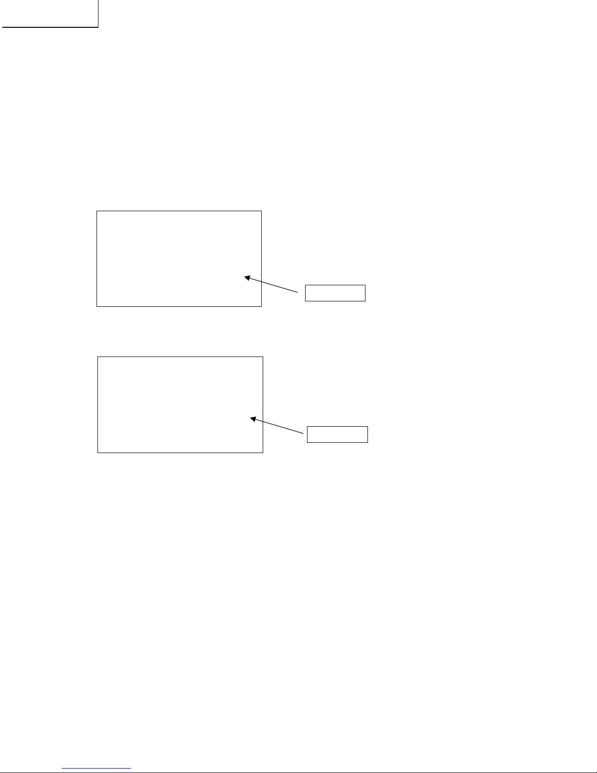
2 When the "OFF" mode is selected, the screen becomes mute, the following message appears and the time is
counted down. (Sound only mode setup process)
The time indication "IN 5 SEC" appearing in the message gets counted down.
IN 5 SEC → IN 4 SEC → IN 3 SEC → IN 2 SEC → IN 1 SEC
When the 5 seconds have passed, the backlight error detect function becomes off, the backlight turns off and
the message disappears. (Sound only mode process)
At a temporary reset, the count-down does not take place and the following message appears.
(In this case too, the backlight error detect function becomes off, the backlight turns off and the message
disappears in 5 seconds.)
3 The key functions in the sound only mode setup process and sound only mode process are referred to in
"Table of Key Allocation in Sound Only Mode" and "Table of Key Functions in Sound Only Mode"
4 To turn off the power with the power key, off-timer or no-signal power supply in the sound only mode, first end
the sound only mode, then call the BACKLIGHT mode, and finally turn off the power.
5 Let's suppose that the power is on and the BACKLIGHT mode is off. In this case, call the BACKLIGHT mode
first and then get started.
6 If the BACKLIGHT mode is turned off with the sound mute, the sound only mode setup process (caution
displayed) goes on with no sound. Once the sound only mode is set up, the sound mute gets cleared (just
when the backlight turns off). The sound volume level at this clearing will be the same as before the sound
mute action.
7 To activate the V-CHIP block, make a temporary reset and keep on the caution display until the block is
unlocked. The screen background will be black, not blue.
8 The closed caption is ignored (including the temporary reset).
Screen mute
Screen mute
BACKLIGHT [OFF] TURNS OFF IN 5 SECS
BACKLIGHT
[OFF] PRESS
BACKLIGHT
TO CANCEL
27
LC-13B6U-S
LC-15B6U-S
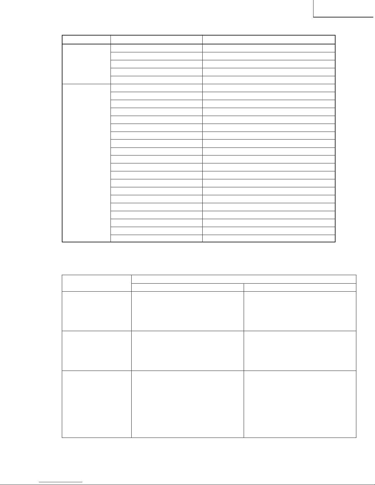
Table of Key Functions in Sound Only Mode
Key
Functions
Sound only mode setup process Sound only mode process
Special reset key » Mute cleared. » Backlight on.
BACKLIGHT » Message deleted. » Backlight error detect on.
» BACKLIGHT mode turned on. Sound only mode clear guide message
(Sound only mode ended) displayed.
(Current BACKLIGHT mode status displayed)
Released key » Mute cleared. » Backlight on.
» Message deleted. » Backlight error detect on.
» BACKLIGHT mode turned on. » Mute cleared
(Sound only mode ended)
» BACKLIGHT mode turned on.
(Sound only mode ended)
Temporary reset key » BACKLIGHT mode temporarily turned on » BACKLIGHT mode temporarily turned on
(Externally OFF). (Externally OFF).
» Message deleted. » Backlight on.
» Description of pressed key displayed for 3 » Backlight error detect on.
seconds.
» Description of pressed key displayed for 3
» Sound only mode setup message displayed. seconds.
(Current BACKLIGHT mode status displayed)» Sound only mode setup message displayed.
(Current BACKLIGHT mode status displayed)
Table of Key Allocation in Sound Only Mode (Unit keys/Remote control keys)
Unit keys
Remote control
Key
POWER
INPUT
MENU
CH
VOL
POWER
PIC.FLIP
DISPLAY
SLEEP
MENU
CURSOR
ENTER
BACKLIGHT
MUTE
MTS
INPUT
VOL
AUDIO ONLY
CH
FLASHBACK
CH1~10/0
CH100
CLOSED CAPTION
AV MODE
MENU RETURN
Allocation
Released
Temporary reset
Released
Temporary reset
Temporary reset
Released
Released
Temporary reset
Temporary reset
Released
Released
Released
Special reset
Temporary reset
Temporary reset
Temporary reset
Temporary reset
Released
Temporary reset
Temporary reset
Temporary reset
Temporary reset
Temporary reset
Released
Released
* When the VOLUME FIXED, INPUT MODE FIXED or other fixed status is set up, this status is given priority.
28
LC-13B6U-S
LC-15B6U-S
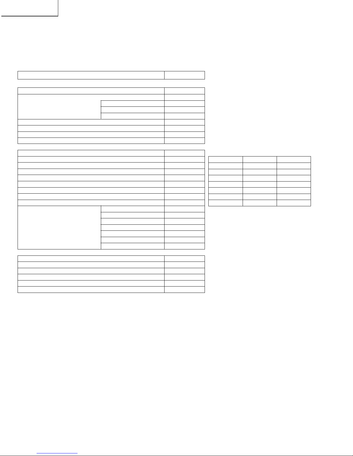
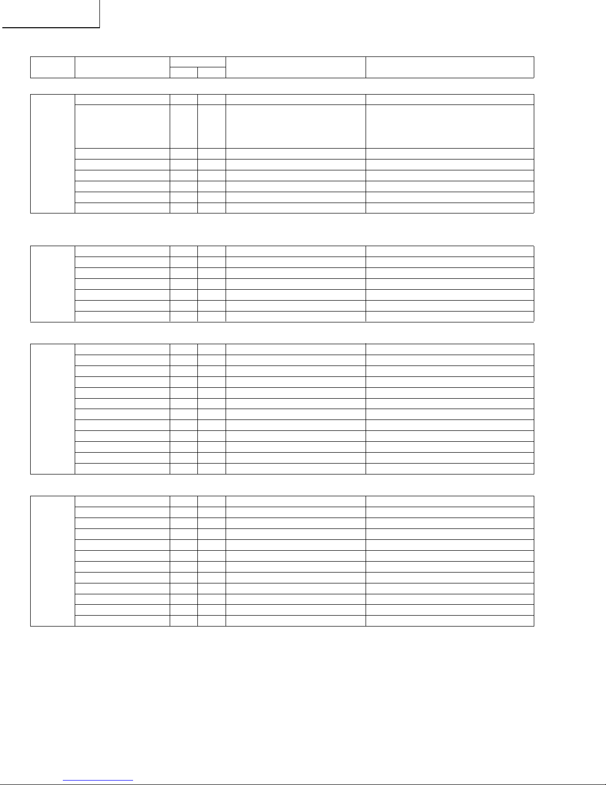
Page No. Item
Initial Value
Function
Response precautions on servicing
13B6U 15B6U (Do not change other items than designated.)
1 MODEL A626 A626
MODEL NAME SELECTION CAN NOT BE CHANGED.
INCH SIZE 13 15
INCH NUMBER SELECTION
USED FOR INITIALIZATION. CHANGE IS
PROHIBITED FOR OTHER CASES. WHEN IT IS
CHANGED, THE DATA
MUST BE RE-WRITTEN AND READJUSTED.
ERROR NO RESET 0 0
LAMP ERROR COUNT AND REST REFER TO LAMP ERROR DETECTION.
PUBLIC MODE OFF OFF
HOTEL MODE SETTING
NOT USED.
V-CHIP 1 1
V-CHIP LINE MUTE SETTING
NOT USED.
CANADIAN VCHIP ON ON
CANADIAN V-CHIP RESPONSE SETTING
NOT USED.
EXT CONTROL OFF OFF
BUSS, UART OPEN
NOT USED.
BLUE BACK 0 0
BLUE BACK ON/OFF SETTING
NOT USED.
ROM AND GAIBU VERSION NUMBERS ARE INDICATED AT THE BOTTOM.
VIDEO ADJUSTMENT
2 COM BIAS 120 120
COMMON BIAS ADJUSTMENT REFER T O ADJUSTING METHOD.
TAMP L 157 157
Y LOWER LIMIT VALUE SETTING IN TAMP ADJUSTMENT
NOT USED.
YDATA — —
DATA READ VALUE IN TAMP ADJUSTMENT
NOT USED.
TAMP H 160 160
Y UPPER LIMIT VALUE SETTING IN TAMP ADJUSTMENT
NOT USED.
NTSC TAMP 70 70 TAMP ADJUSTMENT REFER TO METHOD OF ADJUSTMENT.
PAL-M TAMP 70 70 TAMP ADJUSTMENT REFER TO METHOD OF ADJUSTMENT.
PAL-N TAMP 70 70 TAMP ADJUSTMENT REFER TO METHOD OF ADJUSTMENT.
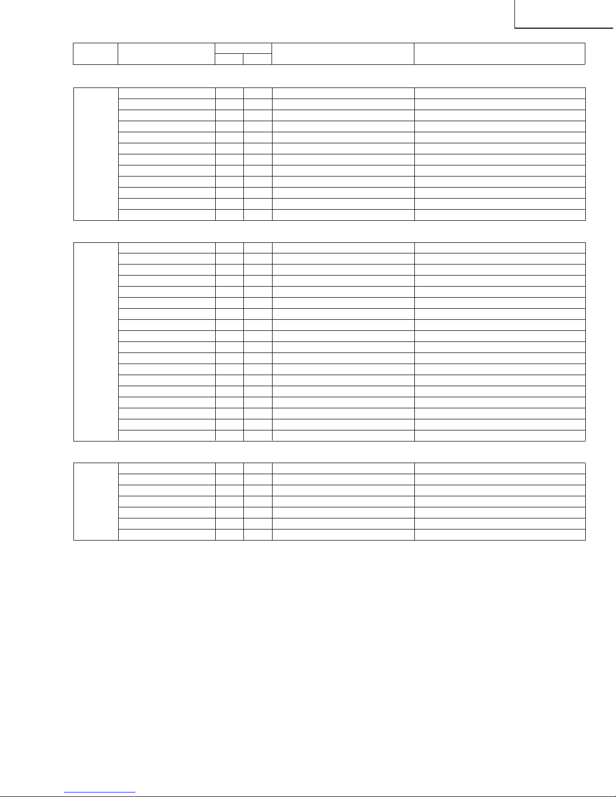
BACKGROUND ADJUSTMENT
3 R CUTOFF 0 0
RED CUT-OFF ADJUSTMENT NOT USED.
G CUTOFF
0
0 GREEN CUT-OFF ADJUSTMENT NOT USED.
B CUTOFF
0
0 BLUE CUT-OFF ADJUSTMENT NOT USED.
GAIN1 64 64 WHITE BALANCE ADJUSTMENT NOT USED.
GAIN2 64 64 WHITE BALANCE ADJUSTMENT NOT USED.
REF
0
0 REFERENCE SETTING NOT USED.
R CUTOFF2
0
0 RED CUT-OFF ADJUSTMENT REFER TO METHOD OF ADJUSTMENT.
G CUTOFF2
0
0 GREEN CUT-OFF ADJUSTMENT REFER TO METHOD OF ADJUSTMENT.
B CUTOFF2
0
0 BLUE CUT-OFF ADJUSTMENT REFER TO METHOD OF ADJUSTMENT.
R-GAIN 64 64 WHITE BALANCE ADJUSTMENT REFER TO METHOD OF ADJUSTMENT.
G-GAIN 64 64 WHITE BALANCE ADJUSTMENT REFER TO METHOD OF ADJUSTMENT.
B-GAIN 64 64 WHITE BALANCE ADJUSTMENT REFER TO METHOD OF ADJUSTMENT.
525I/625I/525P/625P BACKGROUND ADJUSTMENT
4 A R CUTOFF 0 0
RED CUT-OFF ADJUSTMENT IN 525I/625I/525P/625P
NOT USED.
A G CUTOFF
0
0
GREEN CUT-OFF ADJUSTMENT IN 525I/625I/525P/625P
NOT USED.
A B CUTOFF
0
0
BLUE CUT-OFF ADJUSTMENT IN 525I/625I/525P/625P
NOT USED.
A GAIN1 64 64
WHITE BALANCE ADJUSTMENT IN 525I/625I/525P/625P
NOT USED.
A GAIN2 64 64
WHITE BALANCE ADJUSTMENT IN 525I/625I/525P/625P
NOT USED.
A REF
0
0
REFERENCE SETTING IN 525I/625I/525P/625P
NOT USED.
A R CUTOFF2
0
0
RED CUT-OFF ADJUSTMENT IN 525I/625I/525P/625P
REFER TO METHOD OF ADJUSTMENT .
A G CUTOFF2
0
0
GREEN CUT-OFF ADJUSTMENT IN 525I/625I/525P/625P
REFER TO METHOD OF ADJUSTMENT .
A B CUTOFF2
0
0
BLUE CUT-OFF ADJUSTMENT IN 525I/625I/525P/625P
REFER TO METHOD OF ADJUSTMENT .
A R-GAIN 64 64
WHITE BALANCE ADJUSTMENT IN 525I/625I/525P/625P
REFER TO METHOD OF ADJUSTMENT .
A G-GAIN 64 64
WHITE BALANCE ADJUSTMENT IN 525I/625I/525P/625P
REFER TO METHOD OF ADJUSTMENT .
A B-GAIN 64 64
WHITE BALANCE ADJUSTMENT IN 525I/625I/525P/625P
REFER TO METHOD OF ADJUSTMENT .
DEFAULT LISTS OF ADJUSTMENT PROCESS 1ST HIERARCHICAL ITEMS
BASIC SETTINGS
29
LC-13B6U-S
LC-15B6U-S
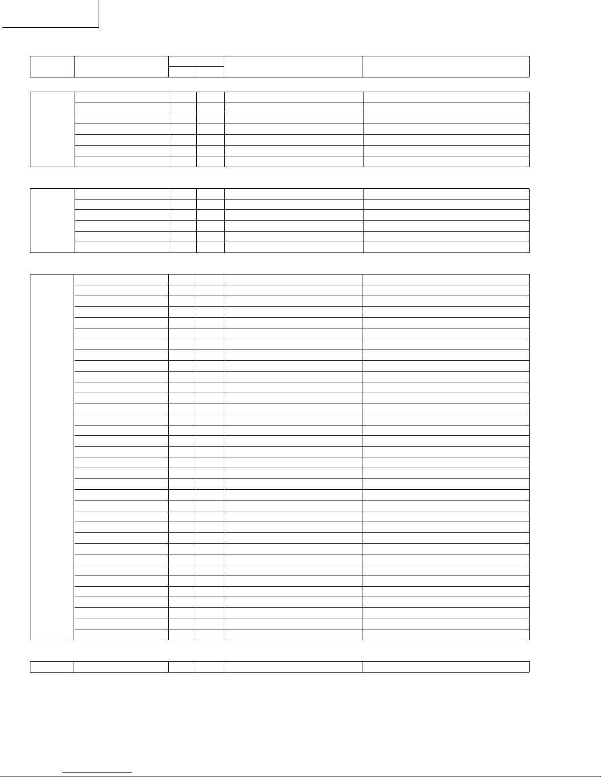
1125I/750P BACKGROUND ADJUSTMENT
5 D R CUTOFF 0 0
1125I/750P
RED CUTOFF ADJUSTMENT
NOT USED.
D G CUTOFF
0
0 1125I/750P
GREEN CUTOFF ADJUSTMENT
NOT USED.
D B CUTOFF
0
0 1125I/750P
BLUE CUTOFF ADJUSTMENT
NOT USED.
D GAIN1 64 64 1125I/750P
WHITE BALANCE ADJUSTMENT
NOT USED.
D GAIN2 64 64 1125I/750P
WHITE BALANCE ADJUSTMENT
NOT USED.
D REF
0
0 1125I/750P
PREFERENCE SETTING
NOT USED.
D R CUTOFF2
0
0 1125I/750P
RED CUTOFF ADJUSTMENT
REFER TO METHOD OF ADJUSTMENT.
D G CUTOFF2
0
0 1125I/750P
GREEN CUTOFF ADJUSTMENT
REFER TO METHOD OF ADJUSTMENT.
D B CUTOFF2
0
0 1125I/750P
BLUE CUTOFF ADJUSTMENT
REFER TO METHOD OF ADJUSTMENT.
D R-GAIN 64 64 1125I/750P
WHITE BALANCE ADJUSTMENT
REFER TO METHOD OF ADJUSTMENT.
D G-GAIN 64 64 1125I/750P
WHITE BALANCE ADJUSTMENT
REFER TO METHOD OF ADJUSTMENT.
D B-GAIN 64 64 1125I/750P
WHITE BALANCE ADJUSTMENT
REFER TO METHOD OF ADJUSTMENT.
1125I/750P AD ADJUSTMENT
7 AD9883 DATA
0000000 0000000
AD9883 DATA WRITE & READ NOT USED.
AD9883 DATA WAIT WAIT WRITE & READ EXECUTION NOT USED.
AUTO GAIN-OFFSET1 OFF OFF
AD9883 GAIN AND OFFSET AUTO-ADJUSTMENT OFF/RUN
REFER TO METHOD OF ADJUSTMENT.
AD R GAIN 30 30
1125I/750P INPUT RED GAIN ADJUSTMENT
REFER TO METHOD OF ADJUSTMENT.
AD G GAIN 125 125
1125I/750P INPUT GREEN GAIN ADJUSTMENT
REFER TO METHOD OF ADJUSTMENT.
AD B GAIN 30 30
1125I/750P INPUT BLUE GAIN ADJUSTMENT
REFER TO METHOD OF ADJUSTMENT.
AD R OFFSET 64 64
1125I/750P INPUT RED OFFSET ADJUSTMENT
REFER TO METHOD OF ADJUSTMENT.
AD G OFFSET 50 50
1125I/750P INPUT GREEN OFFSET ADJUSTMENT
REFER TO METHOD OF ADJUSTMENT.
AD B OFFSET 64 64
1125I/750P INPUT BLUE OFFSET ADJUSTMENT
REFER TO METHOD OF ADJUSTMENT.
RGTAR E0 E0
TARGET VALUE FOR 11251/750P INPUT RED GAIN ADJUSTMENT
NOT USED.
GGTAR 98 98
TARGET VALUE FOR 11251/750P INPUT GREEN GAIN ADJUSTMENT
NOT USED.
BGTAR E0 E0
TARGET VALUE FOR 11251/750P INPUT BLUE GAIN ADJUSTMENT
NOT USED.
RGCAL — —
DISPLAY OF Y LEVEL AND MICRO CALCULATED VALUE
NOT USED.
GGCAL — —
DISPLAY OF Y LEVEL AND MICRO CALCULATED VALUE
NOT USED.
BGCAL — —
DISPLAY OF Y LEVEL AND MICRO CALCULATED VALUE
NOT USED.
ROCAL — —
DISPLAY OF Y LEVEL AND WHITE LEVEL CALCULATED VALUE IN CLAMP FIELD
NOT USED.
GOCAL — —
DISPLAY OF Y LEVEL AND WHITE LEVEL CALCULATED VALUE IN CLAMP FIELD
NOT USED.
BOCAL — —
DISPLAY OF Y LEVEL AND WHITE LEVEL CALCULATED VALUE IN CLAMP FIELD
NOT USED.
INDEX OF VARIOUS SETTINGS
9 I2C DATA
000000000000 000000000000
I2C BUS CONTROL IC DATA WRITE & READ
NOT USED.
I2C DATA WAIT WAIT WRITE & READ EXECUTION NOT USED.
SOUND — — GO TO AUDIO ADJUSTMENT PAGE.
GO TO AUDIO ADJUSTMENT PAGE BY ENTRY KEY.
TC — — GO TO TC ADJUSTMENT PAGE.
GO TO TC ADJUSTMENT PAGE BY ENTRY KEY.
G/A — — GO TO G/A ADJUSTMENT PAGE.
GO TO G/A ADJUSTMENT PAGE BY ENTRY KEY.
TUNER — — GO TO TUNER ADJUSTMENT PAGE.
GO TO TUNER ADJUSTMENT PAGE BY ENTRY KEY.
OTHERS — — GO TO OTHER ADJUSTMENT PAGE.
GO TO OTHER ADJUSTMENT PAGE BY ENTRY KEY.
Page No. Item
Initial Value
Function
Response precautions on servicing
13B6U 15B6U (Do not change other items than designated.)
30
LC-13B6U-S
LC-15B6U-S
SPECIFICATIONS OF AUDIO ADJUSTMENT PROCESS
AUDIO ADJUSTMENT
SOUND1 VOLUME 20 20 USER VOLUME SETTING VALUE NOT USED
AVC OFF OFF AVC SETTING NOT USED
MSP DATA
0000000000 0000000000
AUDIO IC MSP DATA WRITE & READ NOT USED
MSP DATA WAIT WAIT WRITE & READ EXECUTION NOT USED
CARRIER MUTE ON ON
AUDIO OUTPUT SETTING IN TV WITHOUT SYNC
NOT USED
IGR THR 012D 012D IGR THRESH LEVEL NOT USED
SP TEST OFF OFF FOR AUDIO TEST NOT USED
AUDIO ADJUSTMENT
SOUND2 PRESCALE SCART 27 27
PRE-SCALE SETTING (EXT. OUTPUT)
NOT USED.
PRESCALE FM/AM-M 31 31 PRE-SCALE SETTING (TV) NOT USED.
VOICE TEST OFF OFF
TREBLE EMPHASIS TEST (IN USE OF VOICE)
NOT USED.
VOICE LEVEL 6 6
LEVEL SETTING IN TREBLE EMPHASIS (IN USE OF VOICE)
NOT USED.
S. WIDE TEST OFF OFF
SURROUND WIDE TEST (IN USE OF SURROUND WIDE MODE)
NOT USED.
S. WIDE LEVEL 3F 3F
SURROUND WIDE LEVEL SETTING (IN USE OF SURROUND WIDE MODE)
NOT USED.
AUDIO ADJUSTMENT
SOUND3 BASS EQ SET 0 0
TREBLE VALUE FOR USER AUDIO ADJUSTMENT
NOT USED.
TREB EQ SET 0 0
BASS VALUE FOR USER AUDIO ADJUSTMENT
NOT USED.
EQ LIMIT 00 0 0
EQUALIZER LIMIT TABLE 00 AUDIO LEVEL SETTING
NOT USED.
EQ LIMIT 00 +12.0 +12.0
EQUALIZER LIMIT TABLE 00 LIMIT SETTING
NOT USED.
EQ LIMIT 01 10 10
EQUALIZER LIMIT TABLE 01 AUDIO LEVEL SETTING
NOT USED.
EQ LIMIT 01 +12.0 +12.0
EQUALIZER LIMIT TABLE 01 LIMIT SETTING
NOT USED.
EQ LIMIT 02 20 20
EQUALIZER LIMIT TABLE 02 AUDIO LEVEL SETTING
NOT USED.
EQ LIMIT 02 +12.0 +12.0
EQUALIZER LIMIT TABLE 02 LIMIT SETTING
NOT USED.
EQ LIMIT 03 25 25
EQUALIZER LIMIT TABLE 03 AUDIO LEVEL SETTING
NOT USED.
EQ LIMIT 03 +12.0 +12.0
EQUALIZER LIMIT TABLE 03 LIMIT SETTING
NOT USED.
EQ LIMIT 04 30 30
EQUALIZER LIMIT TABLE 04 AUDIO LEVEL SETTING
NOT USED.
EQ LIMIT 04 +12.0 +12.0
EQUALIZER LIMIT TABLE 04 LIMIT SETTING
NOT USED.
EQ LIMIT 05 35 35
EQUALIZER LIMIT TABLE 05 AUDIO LEVEL SETTING
NOT USED.
EQ LIMIT 05 +12.0 +12.0
EQUALIZER LIMIT TABLE 05 LIMIT SETTING
NOT USED.
EQ LIMIT 06 40 40
EQUALIZER LIMIT TABLE 06 AUDIO LEVEL SETTING
NOT USED.
EQ LIMIT 06 +12.0 +12.0
EQUALIZER LIMIT TABLE 06 LIMIT SETTING
NOT USED.
EQ LIMIT 07 42 42
EQUALIZER LIMIT TABLE 07 AUDIO LEVEL SETTING
NOT USED.
EQ LIMIT 07 +12.0 +12.0
EQUALIZER LIMIT TABLE 07 LIMIT SETTING
NOT USED.
EQ LIMIT 08 44 44
EQUALIZER LIMIT TABLE 08 AUDIO LEVEL SETTING
NOT USED.
EQ LIMIT 08 +12.0 +12.0
EQUALIZER LIMIT TABLE 08 LIMIT SETTING
NOT USED.
EQ LIMIT 09 46 46
EQUALIZER LIMIT TABLE 09 AUDIO LEVEL SETTING
NOT USED.
EQ LIMIT 09 +12.0 +12.0
EQUALIZER LIMIT TABLE 09 LIMIT SETTING
NOT USED.
EQ LIMIT 10 48 48
EQUALIZER LIMIT TABLE10 AUDIO LEVEL SETTING
NOT USED.
EQ LIMIT 10 +12.0 +12.0
EQUALIZER LIMIT TABLE 10 LIMIT SETTING
NOT USED.
EQ LIMIT 11 50 50
EQUALIZER LIMIT TABLE 11 AUDIO LEVEL SETTING
NOT USED.
EQ LIMIT 11 +12.0 +12.0
EQUALIZER LIMIT TABLE 11 LIMIT SETTING
NOT USED.
EQ LIMIT 12 52 52
EQUALIZER LIMIT TABLE 12 AUDIO LEVEL SETTING
NOT USED.
EQ LIMIT 12 +12.0 +12.0
EQUALIZER LIMIT TABLE 12 LIMIT SETTING
NOT USED.
EQ LIMIT 13 54 54
EQUALIZER LIMIT TABLE 13 AUDIO LEVEL SETTING
NOT USED.
EQ LIMIT 13 +12.0 +12.0
EQUALIZER LIMIT TABLE 13 LIMIT SETTING
NOT USED.
EQ LIMIT 14 56 56
EQUALIZER LIMIT TABLE 14 AUDIO LEVEL SETTING
NOT USED.
EQ LIMIT 14 +12.0 +12.0
EQUALIZER LIMIT TABLE 14 LIMIT SETTING
NOT USED.
EQ LIMIT 15 58 58
EQUALIZER LIMIT TABLE 15 AUDIO LEVEL SETTING
NOT USED.
EQ LIMIT 15 +12.0 +12.0
EQUALIZER LIMIT TABLE 15 LIMIT SETTING
NOT USED.
AUDIO ADJUSTMENT
SOUND4 HPF VDS OFF OFF OFF
BYPASS FILTER SETTING IN DOLBY VIRTUAL OFF
NOT USED.
Page No. Item
Initial Value
Function
Response precautions on servicing
13B6U 15B6U (Do not change other items than designated.)
 Loading...