

Page 1

SERVICE MANUAL LCD COLOUR TELEVISION
LC-10A3E
TENTATIVE
SERVICE MANUAL
S51T1LC-10A3H
LCD COLOUR TELEVISION
In the interests of user-safety (Required by safety regulations in some countries) the set should be restored
to its original condition and only parts identical to those specified should be used.
» IMPORTANT SERVICE SAFETY PRECAUTION................................................................................. 2
» SPECIFICATIONS ................................................................................................................................ 3
» OPERATION MANUAL ......................................................................................................................... 4
» DIMENSIONS ....................................................................................................................................... 5
» DISASSEMBLY OF THE SET............................................................................................................... 6
» ADJUSTING PROCEDURE OF EACH SECTION ............................................................................... 9
» TROUBLE SHOOTING TABLE ........................................................................................................... 12
» CHASSIS LAYOUT ............................................................................................................................. 16
MODEL LC-10A3E
» BLOCK DIAGRAM.............................................................................................................................. 18
» DESCRIPTION OF SCHEMATIC DIAGRAM ..................................................................................... 19
» SCHEMATIC DIAGRAM ..................................................................................................................... 20
» PRINTED WIRING BOARD ASSEMBLIES........................................................................................ 27
» PARTS LIST
» PACKING OF THE SET ...................................................................................................................... 40
MODEL
LC-10A3E
CONTENTS
Ë
ELECTRICAL PARTS..................................................................................................................... 31
MAIN UNIT ..................................................................................................................................... 31
TERMINAL UNIT............................................................................................................................ 35
OPERATION UNIT ......................................................................................................................... 36
LED UNIT ....................................................................................................................................... 37
Ë
ACCESSORIES PARTS ................................................................................................................. 37
Ë
PACKING PA RTS ........................................................................................................................... 37
Ë
CABINET PARTS LOCATION ........................................................................................................ 38
Ë
CABINET AND MECHANICAL PARTS.......................................................................................... 39
Page
SHARP CORPORATION
1
Page 2

LC-10A3E
12345678901234567890123456789012123456789012345678901234567890121234567890123456789012345678901212
1
2
12345678901234567890123456789012123456789012345678901234567890121234567890123456789012345678901212
12345678901234567890123456789012123456789012345678901234567890121234567890123456789012345678901212
1
2
12345678901234567890123456789012123456789012345678901234567890121234567890123456789012345678901212
Ë
IMPORTANT SERVICE SAFETY PRECAUTION
Service work should be perfomed only by qualified service technicians who are thoroughly familiar with all safety checks and the servicing guidelines which follow:
WARNING
1. For continued safety, no modification of any circuit
should be attempted.
2. Disconnect AC power before ser vicing.
CAUTION: FOR CONTINUED PROTECTION
AGAINST A RISK OF FIRE REPLACE ONLY WITH
SAME TYPE FUSE. F3701 (1.25A, 250V), F3702
(1.25A, 250V), F3751 (2.0A, 250V) FUSE.
BEFORE RETURNING THE RECEIVER
(Fire & Shock Hazard)
Before returning the receiver to the user, perform
the following safety checks:
1. Inspect all lead dress to make certain that leads are
not pinched, and check that hardware is not lodged
between the chassis and other metal parts in the
receiver.
2. Inspect all protective devices such as non-metallic
control knobs, insulation materials, cabinet backs,
adjustment and compartment covers or shields,
isolation resistor-capacitor networks, mechanical
insulators and etc.
3. To be sure that no shock hazard exists, check for
leakage current in the following manner.
• Plug the AC cord directly into a 110~240 volt A C outlet,
and connect the DC power cable into the receiver's
DC jack. (Do not use an isolation transformer for this
test).
• Using two clip leads, connect a 50k ohm, 10 watt resistor
paralleled by a 0.15µF capacitor in series with all
exposed metal cabinet parts and a known earth ground,
such as electrical conduit or electrical ground connected
to an earth ground.
• Use an AC voltmeter ha ving with 5000 ohm per volt, or
higher, sensitivity or measure the AC voltage drop
across the resisor.
• Connect the resistor connection to all exposed metal
parts having a return to the chassis (antenna, metal
cabinet, screw heads, knobs and control shafts,
escutcheon and etc.) and measure the AC voltage drop
across the resistor.
All checks must be repeated with the AC cord plug
connection reversed. (If necessary, a nonpolarized
adaptor plug must be used only for the purpose of
completing these checks.)
Any reading of 35V peak (this corresponds to 0.7
milliamp. peak A C .) or more is e xcessive and indicates
a potential shock hazard which must be corrected
before returning the monitor to the owner .
DVM
AC SCALE
50k ohms.
10W
0.15 µF
TEST PROBE
TO EXPOSED
METAL PARTS
CONNECT TO
KNOWN EARTH
GROUND
234567890123456789012345678901212345678901234567890123456789012123456789012345678901234567890121
SAFETY NOTICE
Many electrical and mechanical parts in LCD television
have special safety-related characteristics.
These characteristics are often not evident from visual
inspection, nor can protection afforded by them be
necessarily increased by using replacement components
rated for higher voltage, wattage and etc.
Replacement parts which have these special safety
characteristics are identified in this manual; electrical
and shaded areas in the
Schematic Diagrams
For continued protection, replacement parts must be
identical to those used in the original circuit.
The use of a substitute replacement parts which do not
have the same safety characteristics as the factory
recommended replacement parts shown in this service
manual, may create shock, fire or other hazards.
components having such features are identified by “ å”
234567890123456789012345678901212345678901234567890123456789012123456789012345678901234567890121
2
Replacement Parts Lists
.
and
Page 3

Specifications
LCD panel...............................................................................................10.4" TFT LCD
Number of dots ..................................................................................921,600 dots VGA
Video colour systems.......................................................................PAL/NTSC/SECAM
TV FUNCTION
TV Standard (CCIR) .....................................................................................I/DK/BG
TV Tuning System.......................................................................Auto preset 100 ch.
STEREO/BILINGUAL ............................................................................ NICAM, IGR
AUTO PRESET...................................................................................................YES
CATV.....................................................................................................~Hyper Band
4-LINE COMB FILTER.............................................................................................. Yes
Luminance ......................................................................................................400 cd/m
Lamp life ................................................................................................... 60,000 Hours
Viewing angles................................................................................................... H : 120°
Audio amplifier .................................................................................................1.0 W × 2
Speakers................................................................................................ 3 × 4 cm, 2 pcs
Terminals
AV1 .......................................................................................... AV-IN 1, S-VIDEO-IN
AV2 ................................................................................................................AV-IN 2
AV OUT .........................................................................................................AV-OUT
ANT......................................................................................................................DIN
H/P ...........................................................................................3.5 mm ø jack (Rear)
OSD Language .......................English/German/Dutch/French/Italian/Spanish/Swedish
Power supply.............................................................. DC 12 V, AC110-240 V, 50/60 Hz
Weight........................................................................................ 1.9 kg w/o accessories
Accessories ............................ R/C, Batteries, Wall mount parts, AC adaptor, AC cord,
........................................... AV cable for mini-jack
LC-10A3E
2
V : 100°
Design and specifications are subject to change without notice.
3
Page 4

LC-10A3E
Operation Manual
Main unit (front view)
Remote sensor window
(The actual location is not visible)
Power/standby indicator
A green indicator lights when the power is on and a red indicator
lights when in the standby mode (the indicator will not light when
the power is off).
Main unit (rear view)
Top control panel
BRIGHT
BRIGHT
Ë
The MUTE, DISPLAY, MENU, Volume (+)/(–), CH (')/("), and TV/VIDEO buttons provide the same
functions as the buttons on the remote control.
(The MENU button has a slightly different function from the remote control button.)
DISPLAY
MENU
MENU
MUTE
Volume (+)/(–)
TV/VIDEO
TV/VIDEO
CH
CH (')/(")
Adjust the set stand to an angle so that
the screen is easily visible. The set
stand can be opened up to 80°.
MAIN POWER
MAIN POWER
Remote control
(POWER)
TV/VIDEO
CHANNEL SELECT
TV/VIDEO
VOL
–
123
456
8
7
/
0
LCDTV
Rear terminal section
AV input 1 terminal
• S-Video input
VS
RL
AUDIO
AUDIO
V
AUDIO
V
HEADPHONE
POWER
MENU
CH
CH
9
MENU
CH (')/("), Cursor control Up/Down
VOL
'
+
Selects next higher channel
"
Selects next lower channel
VOL (+)/( ), Cursor control Right/Left
FLASHBACK
Returns to previous channel
DISPLAY
Press...Displays receiving channel for 10 seconds.
Channel indication reduces in size after
about 10 seconds.
Press again...Removes display.
MUTE
Press...Stops sound.
Press again...Returns sound to previous level.
SOUND MODE SELECTOR
Switching audio mode.
INPUT
DC12V
• Video input
• Audio R/L
AV-IN1
AV-IN2
AV input 2 terminal
AV-OUT
AV output terminal
Headphone output
terminal
DC input terminal
Antenna input terminal
4
Page 5

Dimensions
LC-10A3E
Front View
267
213.2
193
Side View
63.5
47.5
43.5
35
1
81.279.2
1
107.8
22
123
126.5 105.5
49.5
65
Rear View
88.5
72 12.5 14 14 14 15
90.1
15.5 103
30.5
60
177
243.8
(Units: mm)
5
Page 6

LC-10A3E
1. Remove the five lock screws (1) off the cabinet B.
2. Push on the six hooks (2) of the cabinet B and open it slightly.
3. Disconnect all the connectors (3) from the terminal and operation PWBs. Detach the cabinet B.
4. Disconnect all the connectors (4) from the main PWB.
DISASSEMBLY OF THE SET
1
1
1
2
2
1
1
2
2
Cabinet B
2
2
3
P3203
P3204
3
P701
P2001
SC401
3
3
P301
P2001
(Main PWB)
4
P752
P401 SC1201
P701
P2002
4
P751
SC1203
4
Cabinet A
4
6
Page 7
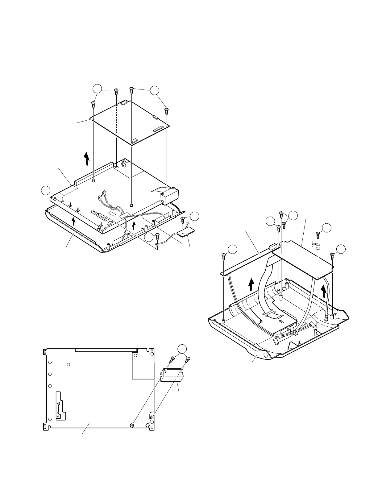
5. Remove the four lock screws (5) off the main PWB.
6. Peel off the one piece of tape (6) and detach the LC display unit.
7. Remove the two lock screws (7) off the remote control PWB.
8. Remove the four lock screws (8) off the terminal PWB.
9. Remove the two lock screws (9) off the operation PWB.
10.Remove the two lock screws (10) off the flexible shield.
LC-10A3E
Main PWB
LC display unit
6
Cabinet A
5
5
Terminal PWB
7
Operation PWB
7
LED PWB
9
9
8
8
8
LC display unit
(rear view)
10
Cabinet B
Flexible shield
7
Page 8

LC-10A3E
11.Undo the seven hooks (11) to release the unit frame.
12.Detach the fluorescent lamp (12).
12
11
11
11
11
Panel holder
11
11
11
8
Page 9

LC-10A3E
ADJUSTING PROCEDURE OF EACH SECTION
The best adjustment is made before shipping. If any position deviation is found or after part replace is performed, adjust
as follows.
1.Preparation for Adjustments
(1)Use the exclusive-use AC adapter or stable DC power supply.
AC adapter: UADP-0225CEPZ
DC power supply: 12 ± 0.5V
2.Special mode setting procedure
(1)Adjustment mode
[Procedure]
• Short-circuit TP2001 to GND, and turn on the power.
• Or short-circuit TP2002 to GND, and turn on the power.
• Or holding down the [TV/VIDEO] key and [MENU] key, turn on the main power, and simultaneously press the
(inspection process) [CH "] key and [VOL– ] key to change the mode to the adjustment mode.
• Each adjustment item is chosen with the [MENU] key, and adjusted with the [VOL] key.
[Description]
The manual adjustment or adjustment through communication with the automatic machine is performed.
(2)Inspection mode
[Procedure]
Holding down the [TV/VIDEO] key and [MENU] key, turn on the power.
[MENU] key is pushed and made inspection mode.
[Description]
• In the ordinary menu select with the [CH] key, and decide with the [VOL] key. Then select “PICTURE”, “TINT (only
NTSC)”, “COLOUR”, “BLACK LEVEL”, “SHARPNESS”, “RED-BLUE”, “GREEN” and “COLOUR SYSTEM” with the
[CH] key, and decide with the [VOL] key. After that, adjust values with the [VOL] key.
• VOLUME, PICTURE, TINT (only NTSC), COLOUR, BLACK LEVEL, SHARPNESS, RED-BLUE, GREEN change as
follows.
(3)Shipping setting mode
[Procedure]
Holding down the [TV/VIDEO] key and [MENU] key, turn on the main power, and simultaneously press the (inspection
process) [CH '] key and [VOL+] key to change the mode to the shipping setting mode.
[Description]
User adjustment and other values are taken as defaults.
If TV is indicated as SETTING COMPLETE, setting has been completed.
ûMin.Û ûCenterÛ ûMax.Û
3.Cancel of special mode
Turn off the main unit power.
4.Initialization
Here is the procedure of initializing the EEPROM and making model number and size settings.
4-1. Get Pins (81) and (82) of the IC2001 (microprocessor) grounded and turn on the power.
4-2. Select a model number (A1, A2H, A2U, A3E). For Model LC-10A3E select A3E.
4-3. Select a size in inches (10, 12, 15, 20). For Model LC-10A3E select 10.
4-4. Get Pins (81) and (82) of the IC2001 (microprocessor) back to normal.
9
Page 10

LC-10A3E
5.Reset of lamp error
6.Adjustments
If the power LED remains red and the power is not turned on, or if repair has been perf ormed, enter the adjustment
mode to reset the lamp error.
For the resetting procedure, refer to " No power" in the "Trouble shooting Table" section.t remote controller:
6-1. +B adjustment
V ary the “+B-ADJ” setting on Page 1 of the adjustment process so that the voltage at pin 49 of SC401 be 5.00
±0.02 V.
Note : Adjust precisely to 5.0 V because this level will be used as supply voltage reference.
6-2. Counter-bias adjustment
Vary the “COM BIAS” setting on Page 2 of the adjustment process so that the contrast be sharpest (black
looks most sinking). The adjustment guideline is around 114 for Model LC-10A3E.
6-3. TAMP adjustment
1) Receive the colour bar signal.
2) See if the "Y" reading on page 2 of the adjustment process is somewhere between BO and BA. If not, make
the "PAL TAMP" adjustment to get the "Y" reading in the range of BO thru BA.
(Adjustment process menu on-screen display on page 2)
0 1 2 3 4 5 6 7 8 9 10 11 12 13 14 15 16 17 18 19 20 21 22 23 24 25 26
0
2
1
2
3
4
5
6
7
8
9
10
11
12
13
COM BIAS 117
PAL 27TAMP
TV H- PEAK ING 3
RCUTOFF 0
GCUTOFF 0
BCUTOFF –1
TA PMH AB
TAMP L B0
G3 B3 R3 00 00 00
G1 B4 Y 00 00 B5
Y Data (75% white )
6-4. White balance adjustment
Vary the “RCUTOFF” and “BCUTOFF” settings to achieve optimum white balance.
Note : For the “RCUTOFF” and “BCUTOFF” settings, keep the readings in the range of -10 to +10. If out of
this range, the user-adjustable range is reduced.
10
Page 11

7.OSD Menu (for pages 1 and 2)
LC-10A3E
Page Item MIN MAX Remarks
1 +B-ADJ 0 255 160 Refer to 5-1
MODEL A3E Refer to 4-2
INCH SIZE 10 Refer to 4-3
TIMER 1
SYSTEM PAL
NTSC PWM FREQ 000 FFF 0C0
PAL PWM FREQ 000 FFF 0BD
TV GAIN OFF
ERROR NO RESET 0
PMUTE 00
2 COMBIAS 0 255 117 Refer to 5-2
PAL TAMP 0 63 27
TV H-PEAKING 0 63 27
R CUT OFF 0 7 0 Refer to 5-3 (around -5)
Initial
Setting
G CUT OFF -15 +15 0
B CUT OFF -15 +15 -1 Refer to 5-3
TAMP H 00 FF BA
TAMP L 00 FF B0
G3 -15 +15 0
B3 00 FF 00
R3 00 FF 00
G1 00 FF 00
B4 00 FF 00
Y00FF00
11
Page 12
LC-10A3E
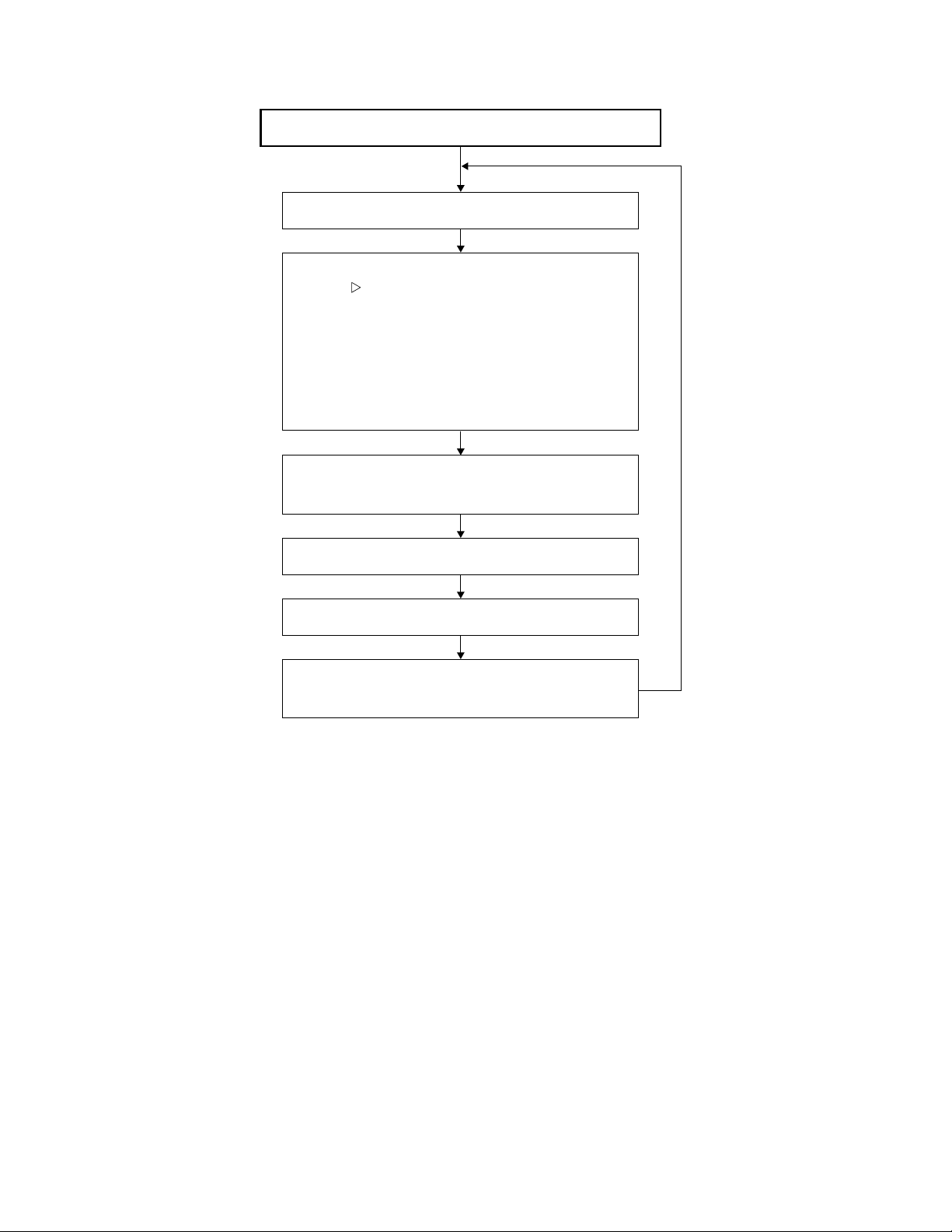
TROUBLE SHOOTING TABLE
No Power (Power LED indicator still in red)
Go to the adjustment process mode.
1
+B-ADJ 160
MODEL A3E
INCH SIZE 10
TIMER 1
NTSC PWM FREQ OCO
PAL PWM FREQ OBD
TV GAIN OFF
ERROR NO RESET 5
PMUTE 00
Move the cursor to ERROR NO RESET
and click on it (to reset to zero).
Turn off the power.
Is the power turned on again?
No
Check the back light lamp, D753, D754, Q757,
Q3600-2 and their peripheral parts as well as pin
(42) of IC2001.
Note:
This model is equipped with the lamp error detection function
that detects the current flowing into the fluorescent lamp and
protects the backlight lamp drive circuit.
If a lamp error is detected, the microprocessor interrupts the
unit and the ERROR NO RESET setting will go up.
When the ERROR NO RESET setting has reached "5", the
microprocessor turns and keeps off the unit's power. To
resume the power, take the above procedure to clear the
ERROR NO RESET setting.
12
Page 13

No picture
at all
Yes
No
Are inputs
and outputs
of IC802 as
specified?
Check all the settings on the microprocessor’s adjust process menu.
No picture
Check IC802
and its
peripheral
parts.
Yes
No
Are inputs
and outputs
of IC1201 as
specified?
Check
IC1201 and
its peripheral
parts.
Check LCD
panel voltage
and
waveform.
No TV and
VIDEO 1
output
Yes
No
Are inputs
and outputs
of IC402 as
specified?
Check IC402
and its
peripheral
parts.
NO
Is input at Pin
(73) of IC802
as specified?
Check IC802,
AV1 line and
their
peripheral
parts.
No TV
output
Yes
No
Are voltages
at Pins (6),
(7) and (9) of
tuner as
specified?
Check the
power line.
Yes
No
Is output at
Pin (19) of
tuner as
specified?
Check the
tuner and its
peripheral
parts.
No
Is input at Pin
(1) of IC402
as specified?
Check the
line in
question.
Yes
Check IC402
and its
peripheral
parts.
Yes
No
Are Pins (2)
and (4) of
IC402 at “H”
and “L”
respectively?
Are Pins (65)
and (66) of
IC2001 at “H”
and “L”
respectively?
No VIDEO
1 output
YES
No
Is input at Pin
(1) of IC402
as specified?
Check the
line in
question.
Yes
No
Are Pins (1)
and (4) of
IC402 both at
“L”?
No VIDEO
2 output
No
Is input at Pin
(74) of IC802
as specified?
Check J3404,
AV line and
their
peripheral
parts.
No S
VIDEO
output
No
Are inputs at
Pins (71) and
(72) of IC802
as specified?
Check
J3301, SY
line, SC line
and
peripheral
parts.
Are Pins (65)
and (66) of
IC2001 both
at “L”?
Check IC402
and its
peripheral
parts.
Yes
Check the
line in
question.
Yes
Check the
line in
question.
TROUBLE SHOOTING TABLE
LC-10A3E
13
Page 14

LC-10A3E
No picture and sound
No colour
No TV colour
No S-VIDEO colour
Yes
No
Do F3701 and F3702
function?
Check all the settings on the microprocessor’s adjust process menu.
No
Are secondary outputs
(+38V, +16V, +9V, +5V, -8V)
of T701 as specified?
Yes
Are the oscillation waveform
at T701’s primary side as
specified?
Yes
No
Disconnect F3701 and
F3702. Is the load side
short-circuited?
Yes
No
Is any of T701’s primary side,
Q701, Q710 and S4701
short-circuited?
Check J3701, its peripheral
parts and connection cable.
Replace F3701 and F3702.
Check S4701 and
connection cable.
Check the secondary-side
load of T701.
Fluorescent lamp failure
Yes
No
Does F3751 function?
Yes
No
Is Pin (34) of IC1201 at “H”?
Yes
No
Are the oscillation waveforms
at the primary side of T751
and T752 as specified?
Yes
Replace F3751.
No
Is input at Pin (71) of IC802
as specified?
Check J3301, SC line and
peripheral parts.
Yes
Check the line, IC1201 and
its peripheral parts.
Check Q751, Q752, T751,
T752, Q753 and their
peripheral parts.
Replace the fluorescent lamp
and check the oscillation
waveform again.
No VIDEO colour
Check all the settings on the microprocessor’s adjust process menu.
TROUBLE SHOOTING TABLE (Continued)
14
Page 15

TROUBLE SHOOTING TABLE (Continued)
No sound
from
speakers
Yes
No
Is Pin (53) of
IC2001 at “L”?
Check all the settings on the microprocessor’s adjust process menu.
No sound
No
Are outputs at
Pins (1) and (7)
of IC903 as
specified?
Yes
No
Are inputs and
outputs of
IC303 as
specified?
Yes
No
Are inputs at
Pins (5) and (8)
as well as
outputs at Pins
(2) and (11), all
of IC301, as
specified?
Muting effect is
on. Check the
FSMU line.
Check IC901,
IC903 and their
peripheral
parts.
Check IC303
and its
peripheral
parts.
Check the line
in question,
IC303 and its
peripheral
parts.
Yes
Check the
speakers and
their peripheral
parts.
No sound
from
headphone
Yes
No
Is Pin (55) of
IC2001 at “L”?
Check the
headphone and
its peripheral
parts.
Check Q306,
J3404 and their
peripheral
parts.
No sound
from output
line
Yes
No
Is Pin (52) of
IC2001 at “L”?
No
Are outputs at
Pins (1) and (7)
of IC902 as
specified?
Yes
Check the line
in question.
Check the
LMUTE line.
Check IC902
and its
peripheral
parts.
TV sound
failure
Yes
No
Is output at Pin
(16) of tuner as
specified?
No
Is input at Pin
(60) of IC901
as specified?
Check the
tuner and its
peripheral
parts.
Check IC901,
Q3301, Q3204,
Q3205 and
their peripheral
parts.
LC-10A3E
15
Page 16

LC-10A3E
CHASSIS LAYOUT
MAIN Unit (Side-A)
J
I
H
G
F
MAIN Unit (Side-B)
E
D
C
B
A
12345678910
16
Page 17

TERMINAL Unit
J
I
H
G
LC-10A3E
F
OPERATION Unit (Side-A)
E
OPERATION Unit (Side-B)
D
LED Unit
C
B
A
10 11 12 13 14 15 16 17 18 19
12345678910
17
Page 18

LC-10A3E
BLOCK DIAGRAM
J
I
H
G
F
E
D
C
B
A
12345678910
18
Page 19

DESCRIPTION OF SCHEMATIC DIAGRAM
VOLTAGE MEASUREMENT CONDITION:
1. When the exclusive-use AC adapter is used, the colour
bar signal of colour bar generator for service is input to
get the normal screen. When the audio is minimized,
the voltage value is measured with the 20 kΩ/V tester.
WAVEFORM MEASUREMENT CONDITION:
1. When the exclusive-use AC adapter is used, the colour
density, lightness and colour hue are set to the center
position, and the signal of colour bar generator for
service is observed to get waveform.
The wave for m test point is indicated with the mark
( ) in the wiring diagram.
INDICATION OF RESISTOR & CAPACITOR:
RESISTOR
1. The unit of resistance “Ω” is omitted.
(K=kΩ=1000 Ω, M=MΩ).
2. All resistors are ± 5%, unless otherwise noted.
(J= ± 5%, F= ± 1%, D= ± 0.5%)
3. All resistors are Carbon type, unless otherwise noted.
C : Solid W : Cement
S : Oxide Film T : Special
N : Metal Coating
LC-10A3E
CAPACITOR
1. All capacitors are mF, unless otherwise noted.
(P=pF=mmF).
2. All capacitors are Ceramic type, unless otherwise
noted.
(ML) : Mylar (TA) : Tantalum
(PF) : Polypro Film (ST) : Styrol
CAUTION:
This circuit diagram is original one, therefore there may be a
slight difference from yours.
IMPORTANT SAFETY NOTICE:
PARTS MARKED WITH “å” ( )ARE
IMPORTANT FOR MAINTAINING THE SAFETY OF
THE SET. BE SURE TO REPLACE THESE PARTS
WITH SPECIFIED ONES FOR MAINTAINING THE
SAFETY AND PERFORMANCE OF THE SET.
10 11 12 13 14 15 16 17 18 19
19
Page 20

LC-10A3E LC-10A3E
Ë
MAIN Unit -1/2
J
I
H
å AND SHADED COMPONENTS=SAFETY RELATED PARTS
G
F
E
D
C
B
A
1234567891011 12 13 14 15 16 17 18 19 20
20~21
Page 21

LC-10A3E LC-10A3E
Ë
MAIN Unit -2/2
J
I
H
å AND SHADED COMPONENTS=SAFETY RELATED PARTS
G
F
E
D
C
B
A
1234567891011 12 13 14 15 16 17 18 19 20
22~23
Page 22

LC-10A3E LC-10A3E
Ë
TERMINAL Unit
J
I
H
å AND SHADED COMPONENTS=SAFETY RELATED PARTS
G
F
E
D
C
å
B
A
1234567891011 12 13 14 15 16 17 18 19 20
24~25
Page 23

LC-10A3E
J
I
H
G
Ë
OPERATION and LED Unit
OPERATION UNIT
F
LED UNIT
E
D
C
B
A
12345678910
26
Page 24

PRINTED WIRING BOARD ASSEMBLIES
J
I
H
G
LC-10A3E
F
E
D
C
B
Main Unit (Side-A)
A
12345678910
27
Page 25

LC-10A3E
J
I
H
G
F
E
D
C
B
Main Unit (Side-B)
A
12345678910
28
Page 26

LC-10A3E
J
LED Unit (Side-A)
I
H
G
F
E
D
C
B
A
Operation Unit (Side-A) Terminal Unit (Side-A)
12345678910
29
Page 27

LC-10A3E
J
I
H
G
LED Unit (Side-B)
F
E
D
C
B
A
Operation Unit (Side-B) Terminal Unit (Side-B)
12345678910
30
Page 28

LC-10A3E
Ref. No. Part No. ★ Description Code
PARTS LIST
PARTS REPLACEMENT
Replacement parts which have these special safety characteristics identified in this manual: electrical components having
such features are identified by
Replacement Parts Lists and schematic diagrams.
The use of a substitute replacement part which does not have
the same safety characteristics as the factory recommended
replacement parts shown in this service manual may create
shock, fire or other hazards.
“
HOW TO ORDER REPLACEMENT PARTS
To have your order filled promptly and correctly, please furnish
the following informations.
1. MODEL NUMBER 2. REF. NO.
3. PART NO. 4. DESCRIPTION
5. CODE
MARK★: SPARE PARTS-DELIVERY SECTION
Ref. No. Part No. ★ Description Code
“å”
and shaded area in the
”
LCD MODULE UNIT
RLCDT0067CEZZ J LCD Module Unit
LAMP UNIT
å KLMP-0116CEZZ J Lamp AZ
PRINTED WIRING BOARD ASSEMBLIES
(NOT REPLACEMENT ITEM)
DUNTKA077DE16 – MAIN Unit —
DUNTKA645DE01 – TERMINAL Unit —
DUNTKA646DE01 – OPERATION Unit —
DUNTKA647DE01 – LED Unit —
Ref. No. Part No. ★ Description Code
DUNTKA077DE16
MAIN UNIT
INTEGRATED CIRCUITS
IC201 VHiNJM2147M-1 J NJM2147M AF
IC301 VHiLA4227//-1 J LA4227 AG
IC303 VHiNJM2283F-1 J NJM2283F AF
IC402 VHiNJM2235M-1 J NJM2235M AE
IC701 VHiAN8005M/-1 J AN8005M AD
IC702 VHiNJM2377M-1 J NJM2377M AK
IC704 VHiBA033FP/-1 J BA033FP AG
IC802 VHiVPC3230D-1 J VPC3230D BG
IC901 RH-iX3371CEZZ J IX3371CE BD
IC902 VHiNJM4560M-1 J NJM4560M AG
IC903 VHiNJM4560M-1 J NJM4560M AG
IC1101 VHiMB8346BV-1 J MB8346BV AN
IC1102 VHiNJM4565V-1 J NJM4565V AF
IC1103 VHiNJM4565V-1 J NJM4565V AF
IC1104 VHiNJM4565V-1 J NJM4565V AF
IC1105 VHiBU4053V/-1 J BU4053V AE
IC1106 VHiNJM4580V-1 J NJM4580V AE
IC1107 VHiNJM4580V-1 J NJM4580V AE
IC1108 VHiNJM4580V-1 J NJM4580V AE
IC1109 VHiNJM353M/-1 J NJM353M AG
IC1110 VHiBU4053V/-1 J BU4053V AE
IC1201 RH-iX3378CEZZ J IX3378CE AY
IC1202 VHiPD485505-2 J PD485505 AY
IC2001 RH-iX3606CEZZ J IX3606CE
IC2002 VHiPST529DM-1 J PST529DM AE
IC2003 VHiTC4W66F/-1 J TC4W66F AE
IC2004 VHiBR24C08F-1 J BR24C08F AF
IC2005 VHiBA7046F/-1 J BA7046F AF
TRANSISTORS
Q201 VS2SC2712Y/-1 J 2SC2712Y AB
Q202 VS2SC2712Y/-1 J 2SC2712Y AB
Q203 VSFMY3/////-1 J FMY3 AB
Q204 VS2SC2712Y/-1 J 2SC2712Y AB
Q302 VS2SA1162Y/-1 J 2SA1162Y AB
Q303 VSDTC314TK/-1 J DTC314TK AC
Q304 VSDTC314TK/-1 J DTC314TK AC
Q306 VSDTC144EE/-1 J DTC144EE AA
Q308 VSDTC144EE/-1 J DTC144EE AA
Q701 VS2SA1162Y/-1 J 2SA1162Y AB
Q702 VS2SK2503//-1 J 2SK2503 AE
Q703 VS2SC2712Y/-1 J 2SC2712Y AB
Q707 VSDTC144EE/-1 J DTC144EE AA
Q708 VSFMMT718//-1 J FMMT718 AE
Q709 VSDTC144EE/-1 J DTC144EE AA
Q710 VS2SA1162Y/-1 J 2SA1162Y AB
Q751 VSFZT1053A/-1 J FZT1053A AG
Q752 VSFZT1053A/-1 J FZT1053A AG
Q753 VS2SA1162Y/-1 J 2SA1162Y AB
Q754 VSDTC114YE/-1 J DTC114YE AB
Q757 VSUPA606T//-1 J UPA606T AD
Q1101 VS2SA1729//-1 J 2SA1729 AF
Q1102 VS2SC4520//-1 J 2SC4520 AE
Q1201 VSDTC144EE/-1 J DTC144EE AA
Q2003 VS2SC2712Y/-1 J 2SC2712Y AB
Q2004 VSDTC144EE/-1 J DTC144EE AA
Q2005 VSDTA144EE/-1 J DTA144EE AA
Q2006 VSDTC144EE/-1 J DTC144EE AA
D201 VHDDAN222//-1 J DAN222 AA
D702 VHDSFPB56//2E J SFPB56 AC
D703 VHD1SS250//1E J 1SS250 AB
D704 VHD1SS250//1E J 1SS250 AB
D705 VHDDAN222//-1 J DAN222 AA
D706 VHDSFPB74//2E J SFPB74 AD
D707 VHDDAN222//-1 J DAN222 AA
D709 VHDDAN222//-1 J DAN222 AA
D710 VHDDAN222//-1 J DAN222 AA
D712 VHDDAN222//-1 J DAN222 AA
D753 VHDiMN10///-1 J IMN10 AB
31
DIODES
Page 29

LC-10A3E
Ref. No. Part No. ★ Description Code
DUNTKA077DE16
MAIN UNIT(Continued)
D754 VHDiMN10///-1 J IMN10 AB
D1101 VHD1SS250//1E J 1SS250 AB
D1102 VHDDAN222//-1 J DAN222 AA
D1201 VHDDAN222//-1 J DAN222 AA
D1202 RH-EX0227CEZZ J Zener Diode, 5.1V AB
PACKAGED CIRCUITS
X801 RCRSC0012CEZZ J Crystal, CRSC0012CE AH
X901 RCRSB0250GEZZ J Crystal, CRSB0250GE AG
FILTER
X2002 RFiLA0107CEZZ J Filter, FiLA0107CE AD
COILS
L701 RCiLC0130CEZZ J Coil, CiLC0130CE AG
L705 RCiLC0057CEZZ J Coil, CiLC0057CE AD
L706 RCiLC0130CEZZ J Coil, CiLC0130CE AG
L752 RCiLC0110CEZZ J Coil, CiLC0110CE AF
L803 VP-1M3R3JR93N J Peaking, 3.3µHAB
L804 RCiLC0055CEZZ J Coil, CiLC0055CE AD
L805 RCiLC0055CEZZ J Coil, CiLC0055CE AD
L806 VP-1M4R7J1R2N J Peaking, 4.7µHAB
L807 VP-1M4R7J1R2N J Peaking, 4.7µHAB
L901 VP-1M4R7J1R2N J Peaking, 4.7µHAB
L902 VP-1M101J7R7N J Peaking, 100µHAC
L1202 VP-1M470J5R4N J Peaking, 47µHAC
L1203 VP-1M220J2R9N J Peaking, 22µHAC
L1204 VP-1M220J2R9N J Peaking, 22µHAC
L1205 VP-1M220J2R9N J Peaking, 22µHAC
TRANSFORMERS
å T701 RTRNZ0778CEZZ J Transformer AM
å T751 RTRNZ0764CEZZ J Transformer AM
å T752 RTRNZ0764CEZZ J Transformer AM
CAPACITORS
C201 VCKYTV1HF104Z J 0.1 50V Ceramic AA
C202 VCKYCY1EF104Z J 0.1 25V Ceramic AA
C203 RC-KZ1025CEZZ J 1 10V Ceramic AB
C204 RC-KZ1025CEZZ J 1 10V Ceramic AB
C205 VCKYCY1EF104Z J 0.1 25V Ceramic AA
C206 VCKYCY1HF103Z J 0.01 50V Ceramic AA
C207 VCEAKM1HW225M J 2.2 50V Electrolytic AB
C301 VCEAPF1CN106M J 10 16V Electrolytic AD
C302 VCEAPF1CN107M J 100 16V Electrolytic AD
C303 VCKYCY1EF104Z J 0.1 25V Ceramic AA
C304 VCEAPF1CN476M J 47 16V Electrolytic AD
C305 VCKYCY1EB223K J 0.022 25V Ceramic AA
C306 VCEAPW1CN477M J 470 16V Electrolytic AE
C307 VCEAPF1HN225M J 2.2 50V Electrolytic AD
C308 VCEAPF1HN225M J 2.2 50V Electrolytic AD
C309 VCKYCY1EB223K J 0.022 25V Ceramic AA
C310 VCEAPF1CN476M J 47 16V Electrolytic AD
C311 VCKYCY1EF104Z J 0.1 25V Ceramic AA
C312 VCEAPF1CN107M J 100 16V Electrolytic AD
C313 VCKYTV1CF105Z J 1 16V Ceramic AB
C314 VCEA4U1CN228M J 2200 16V Electrolytic AE
C316 VCKYCY1EF104Z J 0.1 25V Ceramic AA
C317 VCEAPF1HN105M J 1 50V Electrolytic AD
C318 VCEAPF1HN105M J 1 50V Electrolytic AD
C319 VCEAPF0JW226M J 22 6.3V Electrolytic AB
C403 VCKYTV1AB105K J 1 10V Ceramic AD
C404 VCKYTV1AB105K J 1 10V Ceramic AD
C406 VCKYCY1EF104Z J 0.1 25V Ceramic AA
C408 VCCCCY1HH331J J 330p 50V Ceramic AA
C409 VCCCCY1HH331J J 330p 50V Ceramic AA
C411 VCCCCY1HH331J J 330p 50V Ceramic AA
C701 VCCCCY1HH471J J 470p 50V Ceramic AA
C702 VCKYTV1CF105Z J 1 16V Ceramic AB
C703 VCEAPF1CN226M J 22 16V Electrolytic AD
C704 VCKYTV1CF105Z J 1 16V Ceramic AB
Ref. No. Part No. ★ Description Code
C706 VCKYCY1HB562K J 5600p 50V Ceramic AA
C707 VCKYCY1CF334Z J 0.33 16V Ceramic AA
C708 VCEAPF0JN226M J 22 6.3V Electrolytic AD
C710 VCKYTV1CF105Z J 1 16V Ceramic AB
C711 VCKYCY1EB103K J 0.01 25V Ceramic AA
C712 VCEAPT1CN226M J 22 16V Electrolytic AC
C713 RC-EZ1176CEZZ J 100 16V Electrolytic AK
C716 VCKYTV1CF105Z J 1 16V Ceramic AB
C719 RC-EZ0420CEZZ J 100 25V Electrolytic AE
C721 VCEASD1HN336M J 33 50V Electrolytic AD
C722 VCKYTV1HF104Z J 0.1 50V Ceramic AA
C728 VCKYTV1HF104Z J 0.1 50V Ceramic AA
C729 VCKYTV1CF105Z J 1 16V Ceramic AB
C731 VCCCCY1HH181J J 180p 50V Ceramic AA
C733 RC-EZ0538CEZZ J 330 16V Electrolytic AE
C734 VCKYTV1CF105Z J 1 16V Ceramic AB
C735 RC-EZ0416CEZZ J 330 6.3V Electrolytic AD
C736 RC-EZ0416CEZZ J 330 6.3V Electrolytic AD
C737 RC-EZ1339CEZZ J 220 16V Electrolytic AD
C738 RC-KZ1025CEZZ J 1 10V Ceramic AB
C740 VCEAPF1EN475M J 4.7 25V Electrolytic AC
C741 VCKYTV1CF105Z J 1 16V Ceramic AB
C746 VCKYCY1EF104Z J 0.1 25V Ceramic AA
C747 VCKYTV1HB562K J 5600p 50V Ceramic AA
C748 RC-EZ1339CEZZ J 220 16V Electrolytic AD
C749 RC-EZ1177CEZZ J 150 6.3V Electrolytic AH
C751 VCEA4U1CN228M J 2200 16V Electrolytic AE
C752 RC-FZ0173CEZZ J Capacitor AG
C755 VCKYCY1HB103K J 0.01 50V Ceramic AA
C757 VCKYCY1CB273K J 0.027 16V Ceramic AA
C758 VCKYCY1CB273K J 0.027 16V Ceramic AA
C759 VCEAPF0JN107M J 100 6.3V Electrolytic AD
C760 VCKYTV1HB103K J 0.01 50V Ceramic AA
C761 VCKYTV1HB103K J 0.01 50V Ceramic AA
C762 RC-FZ0174CEZZ J 0.12 100V Mylar AG
C763 VCKYCY1HB562K J 5600p 50V Ceramic AA
C764 VCKYTV1CF105Z J 1 16V Ceramic AB
C765 VCKYTV1CF105Z J 1 16V Ceramic AB
C801 VCEAPF1CN106M J 10 16V Electrolytic AD
C802 VCKYCY1EF104Z J 0.1 25V Ceramic AA
C803 VCCCCY1HH7R0D J 7p 50V Ceramic AA
C804 VCCCCY1HH7R0D J 7p 50V Ceramic AA
C805 RC-KZ1025CEZZ J 1 10V Ceramic AB
C806 RC-KZ1025CEZZ J 1 10V Ceramic AB
C807 VCKYCY1HB331K J 330p 50V Ceramic AA
C808 VCKYCY1HB331K J 330p 50V Ceramic AA
C809 VCEAPK1CN107M J 100 16V Electrolytic AD
C810 VCKYCY1EF104Z J 0.1 25V Ceramic AA
C811 VCKYCY1HB331K J 330p 50V Ceramic AA
C812 RC-KZ1025CEZZ J 1 10V Ceramic AB
C813 RC-KZ1025CEZZ J 1 10V Ceramic AB
C814 VCKYCY1HB102K J 1000p 50V Ceramic AA
C815 VCKYTV1CF684Z J 0.68 16V Ceramic AB
C816 VCKYTV1CF684Z J 0.68 16V Ceramic AB
C817 VCKYTV1CF684Z J 0.68 16V Ceramic AB
C818 RC-KZ1025CEZZ J 1 10V Ceramic AB
C819 RC-KZ1025CEZZ J 1 10V Ceramic AB
C820 VCKYCY1EF104Z J 0.1 25V Ceramic AA
C821 VCEAPW1CN477M J 470 16V Electrolytic AE
C822 RC-KZ1025CEZZ J 1 10V Ceramic AB
C825 RC-KZ1025CEZZ J 1 10V Ceramic AB
C826 VCKYCY1CF224Z J 0.22 16V Ceramic AA
C827 VCKYCY1CF224Z J 0.22 16V Ceramic AA
C830 VCEAPF0GW107M J 100 4V Electrolytic AC
C831 VCKYCY1EF104Z J 0.1 25V Ceramic AA
C835 VCKYCY1CF224Z J 0.22 16V Ceramic AA
C839 VCKYCY1CF224Z J 0.22 16V Ceramic AA
C840 VCKYCY1CF224Z J 0.22 16V Ceramic AA
C841 VCKYCY1CF224Z J 0.22 16V Ceramic AA
C842 VCEAPF0GW107M J 100 4V Electrolytic AC
C844 VCKYCY1EF104Z J 0.1 25V Ceramic AA
C848 VCEAPF0JW107M J 100 6.3V Electrolytic AC
C874 RC-KZ1025CEZZ J 1 10V Ceramic AB
C875 RC-KZ1025CEZZ J 1 10V Ceramic AB
C876 VCEAPF0GW107M J 100 4V Electrolytic AC
32
Page 30

LC-10A3E
Ref. No. Part No. ★ Description Code
DUNTKA077DE16
MAIN UNIT(Continued)
C878 RC-KZ1025CEZZ J 1 10V Ceramic AB
C879 VCKYTV1CF684Z J 0.68 16V Ceramic AB
C902 VCKYCY1EF104Z J 0.1 25V Ceramic AA
C905 VCEAPF1CW106M J 10 16V Electrolytic AB
C906 VCEAPF1CW106M J 10 16V Electrolytic AB
C909 VCKYCY1HB682K J 6800p 50V Ceramic AA
C910 VCKYCY1HB682K J 6800p 50V Ceramic AA
C911 VCEAPF1CW106M J 10 16V Electrolytic AB
C912 VCEAPF1CW106M J 10 16V Electrolytic AB
C913 VCKYCY1EF104Z J 0.1 25V Ceramic AA
C914 RC-EZ0417CEZZ J 150 16V Electrolytic AD
C915 VCEAPF0JW336M J 33 6.3V Electrolytic AB
C916 VCKYCY1EF104Z J 0.1 25V Ceramic AA
C919 RC-KZ1025CEZZ J 1 10V Ceramic AB
C920 RC-KZ1025CEZZ J 1 10V Ceramic AB
C921 RC-KZ1025CEZZ J 1 10V Ceramic AB
C922 RC-KZ1025CEZZ J 1 10V Ceramic AB
C923 VCKYCY1EF104Z J 0.1 25V Ceramic AA
C924 VCEAPF1CW106M J 10 16V Electrolytic AB
C925 RC-KZ1025CEZZ J 1 10V Ceramic AB
C927 VCCCCY1HH560J J 56p 50V Ceramic AA
C928 VCCCCY1HH560J J 56p 50V Ceramic AA
C929 VCCCCY1HH560J J 56p 50V Ceramic AA
C930 VCCCCY1HH5R0C J 5p 50V Ceramic AA
C931 VCCCCY1HH5R0C J 5p 50V Ceramic AA
C932 VCKYCY1EF104Z J 0.1 25V Ceramic AA
C933 RC-EZ0417CEZZ J 150 16V Electrolytic AD
C935 VCEAPF1CW226M J 22 16V Electrolytic AB
C937 RC-EZ0417CEZZ J 150 16V Electrolytic AD
C938 RC-EZ0417CEZZ J 150 16V Electrolytic AD
C939 VCKYCY1HB561K J 560p 50V Ceramic AA
C940 VCKYCY1HB152K J 1500p 50V Ceramic AA
C941 VCKYCY1HB152K J 1500p 50V Ceramic AA
C942 VCKYCY1HB561K J 560p 50V Ceramic AA
C943 VCKYCY1EF104Z J 0.1 25V Ceramic AA
C944 VCEAPF1CW106M J 10 16V Electrolytic AB
C945 VCEAPF1HW225M J 2.2 50V Electrolytic AB
C946 VCEAPF1HW225M J 2.2 50V Electrolytic AB
C954 VCEAPF1CW106M J 10 16V Electrolytic AB
C955 VCKYTV1CF105Z J 1 16V Ceramic AB
C956 VCKYTV1CF105Z J 1 16V Ceramic AB
C957 VCEAPF1EW475M J 4.7 25V Electrolytic AB
C958 VCEAPF1EW475M J 4.7 25V Electrolytic AB
C961 VCKYCY1HB102K J 1000p 50V Ceramic AA
C962 VCKYCY1HB102K J 1000p 50V Ceramic AA
C963 VCKYCY1HB102K J 1000p 50V Ceramic AA
C964 VCKYCY1HB102K J 1000p 50V Ceramic AA
C1101 VCKYCY1EF104Z J 0.1 25V Ceramic AA
C1102 VCKYCY1EF104Z J 0.1 25V Ceramic AA
C1103 VCKYCY1EF104Z J 0.1 25V Ceramic AA
C1104 VCKYCY1EF104Z J 0.1 25V Ceramic AA
C1105 VCKYCY1EF104Z J 0.1 25V Ceramic AA
C1106 VCKYCY1EF104Z J 0.1 25V Ceramic AA
C1107 VCKYCY1EF104Z J 0.1 25V Ceramic AA
C1108 VCKYCY1EF104Z J 0.1 25V Ceramic AA
C1109 VCKYCY1EF104Z J 0.1 25V Ceramic AA
C1110 VCKYCY1EF104Z J 0.1 25V Ceramic AA
C1111 VCKYCY1EF104Z J 0.1 25V Ceramic AA
C1112 VCKYCY1EF104Z J 0.1 25V Ceramic AA
C1113 VCKYCY1EF104Z J 0.1 25V Ceramic AA
C1114 VCKYCY1EF104Z J 0.1 25V Ceramic AA
C1115 VCKYCY1EF104Z J 0.1 25V Ceramic AA
C1116 VCKYCY1EF104Z J 0.1 25V Ceramic AA
C1117 VCCCCY1HH560J J 56p 50V Ceramic AA
C1118 VCKYCY1EF104Z J 0.1 25V Ceramic AA
C1119 VCKYTV1CF105Z J 1 16V Ceramic AB
C1120 VCKYTV1EF104Z J 0.1 25V Ceramic AB
C1122 VCKYTV1CF105Z J 1 16V Ceramic AB
C1123 VCKYCY1EF104Z J 0.1 25V Ceramic AA
C1124 VCKYCY1EF104Z J 0.1 25V Ceramic AA
C1127 VCEAPF1CN107M J 100 16V Electrolytic AD
C1128 VCE9PF1CN106M J 10 16V Electrolytic AD
Ref. No. Part No. ★ Description Code
C1201 VCCCCY1HH220J J 22p 50V Ceramic AA
C1202 VCKYCY1HB103K J 0.01 50V Ceramic AA
C1203 VCKYCY1EF104Z J 0.1 25V Ceramic AA
C1204 VCCCCY1HH220J J 22p 50V Ceramic AA
C1205 VCCCCY1HH220J J 22p 50V Ceramic AA
C1206 VCEAPF1HN106M J 10 50V Electrolytic AD
C1207 VCKYCY1EF104Z J 0.1 25V Ceramic AA
C1209 VCEAPF0JW107M J 100 6.3V Electrolytic AC
C1210 VCEAPF0GW107M J 100 4V Electrolytic AC
C1211 VCKYCY1EF104Z J 0.1 25V Ceramic AA
C1212 VCKYCY1EF104Z J 0.1 25V Ceramic AA
C1213 VCEAPF0JW107M J 100 6.3V Electrolytic AC
C1214 VCEAPF0GW107M J 100 4V Electrolytic AC
C1215 RC-KZ1025CEZZ J 1 10V Ceramic AB
C1217 VCEAPF1CW226M J 22 16V Electrolytic AB
C1218 VCEAPF1CN106M J 10 16V Electrolytic AD
C2001 VCKYCY1HB102K J 1000p 50V Ceramic AA
C2002 VCCCCY1HH221J J 220p 50V Ceramic AA
C2003 VCEAPF1HW105M J 1 50V Electrolytic AB
C2006 VCKYCY1EF104Z J 0.1 25V Ceramic AA
C2007 VCKYCY1EF104Z J 0.1 25V Ceramic AA
C2009 VCKYCY1EF104Z J 0.1 25V Ceramic AA
C2010 VCKYCY1EF104Z J 0.1 25V Ceramic AA
C2017 VCKYCY1EF104Z J 0.1 25V Ceramic AA
C2018 VCCCCY1HH101J J 100p 50V Ceramic AA
C2019 VCKYTV1AB105K J 1 10V Ceramic AD
C2020 VCKYCY1HB102K J 1000p 50V Ceramic AA
C2021 VCEAPF1AW476M J 47 10V Electrolytic AB
C2022 VCKYCY1EF104Z J 0.1 25V Ceramic AA
C2023 VCKYTV1AB105K J 1 10V Ceramic AD
C2024 VCKYCY1HB222K J 2200p 50V Ceramic AA
RESISTORS
R201 VRS-CY1JF102J J 1k 1/16W Metal Oxide AA
R202 VRS-CY1JF103F J 10k 1/16W Metal Oxide AA
R203 VRS-CY1JF102F J 1k 1/16W Metal Oxide AA
R204 VRS-CY1JF473F J 47k 1/16W Metal Oxide AA
R205 VRS-CY1JF103J J 10k 1/16W Metal Oxide AA
R206 VRS-CY1JF103F J 10k 1/16W Metal Oxide AA
R207 VRS-CY1JF622F J 6.2k 1/16W Metal Oxide AA
R208 VRS-CY1JF473F J 47k 1/16W Metal Oxide AA
R209 VRS-CY1JF123F J 12k 1/16W Metal Oxide AA
R210 VRS-CY1JF242F J 2.4k 1/16W Metal Oxide AA
R211 VRS-CY1JF332F J 3.3k 1/16W Metal Oxide AA
R212 VRS-CY1JF332F J 3.3k 1/16W Metal Oxide AA
R213 VRS-CY1JF682F J 6.8k 1/16W Metal Oxide AA
R214 VRS-CY1JF122F J 1.2k 1/16W Metal Oxide AA
R215 VRS-CY1JF102J J 1k 1/16W Metal Oxide AA
R216 VRS-CY1JF153J J 15k 1/16W Metal Oxide AA
R217 VRS-CY1JF102J J 1k 1/16W Metal Oxide AA
R218 VRS-CY1JF391J J 390 1/16W Metal Oxide AA
R219 VRS-TV1JD103J J 10k 1/16W Metal Oxide AA
R220 VRS-CY1JF102J J 1k 1/16W Metal Oxide AA
R301 VRS-CY1JF000J J 0 1/16W Metal Oxide AA
R302 VRS-TX2HF8R2J J 8.2 1/2W Metal Oxide AA
R303 VRS-CY1JF561J J 560 1/16W Metal Oxide AA
R304 VRS-CY1JF561J J 560 1/16W Metal Oxide AA
R305 VRS-TX2HF8R2J J 8.2 1/2W Metal Oxide AA
R308 VRS-CY1JF223J J 22k 1/16W Metal Oxide AA
R309 VRS-TW2ED222J J 2.2k 1/4W Metal Oxide AA
R310 VRS-CY1JF223J J 22k 1/16W Metal Oxide AA
R311 VRS-CY1JF223J J 22k 1/16W Metal Oxide AA
R314 VRS-CY1JF472J J 4.7k 1/16W Metal Oxide AA
R315 VRS-CY1JF392J J 3.9k 1/16W Metal Oxide AA
R316 VRS-CY1JF472J J 4.7k 1/16W Metal Oxide AA
R317 VRS-CY1JF392J J 3.9k 1/16W Metal Oxide AA
R324 VRS-CY1JF472J J 4.7k 1/16W Metal Oxide AA
R327 VRS-CY1JF000J J 0 1/16W Metal Oxide AA
R328 VRS-CY1JF104J J 100k 1/16W Metal Oxide AA
R329 VRS-CY1JF104J J 100k 1/16W Metal Oxide AA
R331 VRS-CY1JF000J J 0 1/16W Metal Oxide AA
R401 VRS-CY1JF101J J 100 1/16W Metal Oxide AA
R402 VRS-CY1JF000J J 0 1/16W Metal Oxide AA
R403 VRS-CY1JF101J J 100 1/16W Metal Oxide AA
R404 VRS-CY1JF101J J 100 1/16W Metal Oxide AA
33
Page 31

LC-10A3E
Ref. No. Part No. ★ Description Code
DUNTKA077DE16
MAIN UNIT(Continued)
R405 VRS-CY1JF101J J 100 1/16W Metal Oxide AA
R406 VRS-CY1JF101J J 100 1/16W Metal Oxide AA
R407 VRS-CY1JF103J J 10k 1/16W Metal Oxide AA
R408 VRS-CY1JF103J J 10k 1/16W Metal Oxide AA
R409 VRS-CY1JF101J J 100 1/16W Metal Oxide AA
R410 VRS-CY1JF101J J 100 1/16W Metal Oxide AA
R411 VRS-CY1JF101J J 100 1/16W Metal Oxide AA
R418 VRS-CY1JF101J J 100 1/16W Metal Oxide AA
R420 VRS-CY1JF101J J 100 1/16W Metal Oxide AA
R424 VRS-CY1JF101J J 100 1/16W Metal Oxide AA
R430 VRS-CA1JF101J J 100 1/16W Metal Oxide AA
R434 VRS-CY1JF105J J 1M 1/16W Metal Oxide AA
R435 VRS-CY1JF105J J 1M 1/16W Metal Oxide AA
R436 VRS-CY1JF105J J 1M 1/16W Metal Oxide AA
R437 VRS-CY1JF000J J 0 1/16W Metal Oxide AA
R701 VRS-CY1JF1R0J J 1 1/16W Metal Oxide AA
R702 VRS-CY1JF154J J 150k 1/16W Metal Oxide AA
R703 VRS-CY1JF274J J 270k 1/16W Metal Oxide AA
R704 VRS-TQ2BD000J J 0 1/8W Metal Oxide AA
R705 VRS-TX2HF000J J 0 1/2W Metal Oxide AA
R706 VRS-CR3AD821J J 820 1W Metal Oxide AC
R707 VRS-CY1JF000J J 0 1/16W Metal Oxide AA
R708 VRS-CY1JF272F J 2.7k 1/16W Metal Oxide AA
R709 VRS-CY1JF123F J 12k 1/16W Metal Oxide AA
R711 VRS-CY1JF184J J 180k 1/16W Metal Oxide AA
R712 VRS-CY1JF683F J 68k 1/16W Metal Oxide AA
R713 VRS-CY1JF133F J 13k 1/16W Metal Oxide AA
R715 VRS-CY1JF000J J 0 1/16W Metal Oxide AA
R716 VRS-TX2HF000J J 0 1/2W Metal Oxide AA
R717 VRS-CY1JF152F J 1.5k 1/16W Metal Oxide AA
R718 VRS-CY1JF274J J 270k 1/16W Metal Oxide AA
R719 VRS-CY1JF563F J 56k 1/16W Metal Oxide AA
R720 VRS-CY1JF473J J 47k 1/16W Metal Oxide AA
R721 VRS-CY1JF103J J 10k 1/16W Metal Oxide AA
R722 VRS-CY1JF105J J 1M 1/16W Metal Oxide AA
R723 VRS-CY1JF682J J 6.8k 1/16W Metal Oxide AA
R724 VRS-TQ2BD000J J 0 1/8W Metal Oxide AA
R725 VRS-CY1JF1R0J J 1 1/16W Metal Oxide AA
R726 VRS-CY1JF1R0J J 1 1/16W Metal Oxide AA
R729 VRS-TQ2BD000J J 0 1/8W Metal Oxide AA
R731 VRS-TQ2BD000J J 0 1/8W Metal Oxide AA
R732 VRS-TW2ED222J J 2.2k 1/4W Metal Oxide AA
R733 VRS-TQ2BD683J J 68k 1/8W Metal Oxide AA
R734 VRS-CY1JF393J J 39k 1/16W Metal Oxide AA
R735 VRS-CY1JF223J J 22k 1/16W Metal Oxide AA
R736 VRS-CY1JF1R0J J 1 1/16W Metal Oxide AA
R737 VRS-CY1JF472J J 4.7k 1/16W Metal Oxide AA
R738 VRS-TW2ED102J J 1k 1/4W Metal Oxide AA
R739 VRS-CY1JF102J J 1k 1/16W Metal Oxide AA
R740 VRS-CY1JF102J J 1k 1/16W Metal Oxide AA
R741 VRS-CY1JF000J J 0 1/16W Metal Oxide AA
R742 VRS-CY1JF000J J 0 1/16W Metal Oxide AA
R747 VRS-CY1JF000J J 0 1/16W Metal Oxide AA
R748 VRS-CY1JF000J J 0 1/16W Metal Oxide AA
R751 VRS-TW2ED392J J 3.9k 1/4W Metal Oxide AA
R752 VRS-TW2ED392J J 3.9k 1/4W Metal Oxide AA
R753 VRS-CY1JF333J J 33k 1/16W Metal Oxide AA
R754 VRS-CY1JF103J J 10k 1/16W Metal Oxide AA
R765 VRS-CY1JF103J J 10k 1/16W Metal Oxide AA
R766 VRS-CA1JF821J J 820 1/16W Metal Oxide AA
R768 VRS-CA1JF104J J 100k 1/16W Metal Oxide AA
R770 VRS-CA1JF562J J 5.6k 1/16W Metal Oxide AA
R772 VRS-CY1JF563J J 56k 1/16W Metal Oxide AA
R773 VRS-TW2ED000J J 0 1/4W Metal Oxide AB
R774 VRS-CY1JF000J J 0 1/16W Metal Oxide AA
R801 VRS-CB1JF221J J 220 1/16W Metal Oxide AC
R802 VRS-CB1JF220J J 22 1/16W Metal Oxide AC
R803 VRS-CB1JF220J J 22 1/16W Metal Oxide AC
R804 VRS-CA1JF101J J 100 1/16W Metal Oxide AA
R806 VRS-CY1JF221J J 220 1/16W Metal Oxide AA
R809 VRS-CY1JF750J J 75 1/16W Metal Oxide AA
R810 VRS-CB1JF220J J 22 1/16W Metal Oxide AC
Ref. No. Part No. ★ Description Code
R811 VRS-CY1JF222J J 2.2k 1/16W Metal Oxide AA
R812 VRS-CY1JF000J J 0 1/16W Metal Oxide AA
R813 VRS-CB1JF220J J 22 1/16W Metal Oxide AC
R814 VRS-CY1JF332J J 3.3k 1/16W Metal Oxide AA
R815 VRS-CY1JF000J J 0 1/16W Metal Oxide AA
R816 VRS-CA1JF470J J 47 1/16W Metal Oxide AB
R819 VRS-CY1JF000J J 0 1/16W Metal Oxide AA
R826 VRS-CY1JF101J J 100 1/16W Metal Oxide AA
R831 VRS-CY1JF102J J 1k 1/16W Metal Oxide AA
R832 VRS-CY1JF102J J 1k 1/16W Metal Oxide AA
R833 VRS-CY1JF102J J 1k 1/16W Metal Oxide AA
R834 VRS-CY1JF102J J 1k 1/16W Metal Oxide AA
R852 VRS-CY1JF000J J 0 1/16W Metal Oxide AA
R860 VRS-CY1JF000J J 0 1/16W Metal Oxide AA
R861 VRS-CY1JF000J J 0 1/16W Metal Oxide AA
R901 VRS-CY1JF101J J 100 1/16W Metal Oxide AA
R902 VRS-CY1JF101J J 100 1/16W Metal Oxide AA
R903 VRS-CY1JF101J J 100 1/16W Metal Oxide AA
R905 VRS-CY1JF000J J 0 1/16W Metal Oxide AA
R909 VRS-CY1JF102J J 1k 1/16W Metal Oxide AA
R910 VRS-CY1JF102J J 1k 1/16W Metal Oxide AA
R913 VRS-CY1JF000J J 0 1/16W Metal Oxide AA
R914 VRS-CY1JF000J J 0 1/16W Metal Oxide AA
R915 VRS-CY1JF000J J 0 1/16W Metal Oxide AA
R916 VRS-CY1JF000J J 0 1/16W Metal Oxide AA
R917 VRS-CY1JF105J J 1M 1/16W Metal Oxide AA
R918 VRS-CY1JF822F J 8.2k 1/16W Metal Oxide AA
R919 VRS-CY1JF822F J 8.2k 1/16W Metal Oxide AA
R920 VRS-CY1JF822F J 8.2k 1/16W Metal Oxide AA
R921 VRS-CY1JF822F J 8.2k 1/16W Metal Oxide AA
R922 VRS-CY1JF223J J 22k 1/16W Metal Oxide AA
R923 VRS-CY1JF223J J 22k 1/16W Metal Oxide AA
R924 VRS-CY1JF473J J 47k 1/16W Metal Oxide AA
R925 VRS-CY1JF473J J 47k 1/16W Metal Oxide AA
R951 VRS-CY1JF000J J 0 1/16W Metal Oxide AA
R954 VRS-CY1JF000J J 0 1/16W Metal Oxide AA
R958 VRS-CY1JF104J J 100k 1/16W Metal Oxide AA
R959 VRS-CY1JF104J J 100k 1/16W Metal Oxide AA
R960 VRS-CY1JF104J J 100k 1/16W Metal Oxide AA
R961 VRS-CY1JF104J J 100k 1/16W Metal Oxide AA
R962 VRS-CY1JF153J J 15k 1/16W Metal Oxide AA
R963 VRS-CY1JF223J J 22k 1/16W Metal Oxide AA
R964 VRS-CY1JF473J J 47k 1/16W Metal Oxide AA
R965 VRS-CY1JF473J J 47k 1/16W Metal Oxide AA
R966 VRS-CY1JF152J J 1.5k 1/16W Metal Oxide AA
R967 VRS-CY1JF152J J 1.5k 1/16W Metal Oxide AA
R968 VRS-CY1JF103J J 10k 1/16W Metal Oxide AA
R969 VRS-CY1JF103J J 10k 1/16W Metal Oxide AA
R1101 VRS-CA1JF333J J 33k 1/16W Metal Oxide AA
R1102 VRS-CA1JF103J J 10k 1/16W Metal Oxide AA
R1103 VRS-CA1JF103J J 10k 1/16W Metal Oxide AA
R1104 VRS-CA1JF333J J 33k 1/16W Metal Oxide AA
R1105 VRS-CY1JF104J J 100k 1/16W Metal Oxide AA
R1106 VRS-CA1JF333J J 33k 1/16W Metal Oxide AA
R1107 VRS-CA1JF103J J 10k 1/16W Metal Oxide AA
R1108 VRS-CA1JF103J J 10k 1/16W Metal Oxide AA
R1109 VRS-CA1JF333J J 33k 1/16W Metal Oxide AA
R1110 VRS-CY1JF104J J 100k 1/16W Metal Oxide AA
R1111 VRS-CY1JF104J J 100k 1/16W Metal Oxide AA
R1112 VRS-CY1JF103F J 10k 1/16W Metal Oxide AA
R1113 VRS-CA1JF333J J 33k 1/16W Metal Oxide AA
R1114 VRS-CY1JF103F J 10k 1/16W Metal Oxide AA
R1115 VRS-CY1JF102J J 1k 1/16W Metal Oxide AA
R1116 VRS-CY1JF102J J 1k 1/16W Metal Oxide AA
R1117 VRS-CY1JF102J J 1k 1/16W Metal Oxide AA
R1118 VRS-CY1JF823F J 82k 1/16W Metal Oxide AA
R1119 VRS-CY1JF472F J 4.7k 1/16W Metal Oxide AA
R1120 VRS-TW2ED5R6J J 5.6 1/4W Metal Oxide AA
R1121 VRS-CY1JF181J J 180 1/16W Metal Oxide AA
R1123 VRS-CY1JF181J J 180 1/16W Metal Oxide AA
R1124 VRS-CY1JF472F J 4.7k 1/16W Metal Oxide AA
R1125 VRS-TW2ED101J J 100 1/4W Metal Oxide AA
R1126 VRS-CY1JF000J J 0 1/16W Metal Oxide AA
R1127 VRS-TX2HF000J J 0 1/2W Metal Oxide AA
R1129 VRS-CY1JF563F J 56k 1/16W Metal Oxide AA
34
Page 32

LC-10A3E
Ref. No. Part No. ★ Description Code
DUNTKA077DE16
MAIN UNIT(Continued)
R1130 VRS-TW2ED5R6J J 5.6 1/4W Metal Oxide AA
R1132 VRS-CY1JF000J J 0 1/16W Metal Oxide AA
R1133 VRS-CY1JF223F J 22k 1/16W Metal Oxide AA
R1134 VRS-CY1JF822F J 8.2k 1/16W Metal Oxide AA
R1135 VRS-CY1JF561J J 560 1/16W Metal Oxide AA
R1136 VRS-CY1JF000J J 0 1/16W Metal Oxide AA
R1137 VRS-CY1JF000J J 0 1/16W Metal Oxide AA
R1138 VRS-CY1JF000J J 0 1/16W Metal Oxide AA
R1143 VRS-CY1JF103J J 10k 1/16W Metal Oxide AA
R1144 VRS-CY1JF103J J 10k 1/16W Metal Oxide AA
R1145 VRS-CY1JF103J J 10k 1/16W Metal Oxide AA
R1146 VRS-CY1JF103J J 10k 1/16W Metal Oxide AA
R1147 VRS-CY1JF100J J 10 1/16W Metal Oxide AA
R1149 VRS-CY1JF562J J 5.6k 1/16W Metal Oxide AA
R1150 VRS-CY1JF000J J 0 1/16W Metal Oxide AA
R1202 VRS-CB1JF220J J 22 1/16W Metal Oxide AC
R1203 VRS-CA1JF220J J 22 1/16W Metal Oxide AA
R1204 VRS-CB1JF220J J 22 1/16W Metal Oxide AC
R1205 VRS-CA1JF220J J 22 1/16W Metal Oxide AA
R1206 VRS-CB1JF220J J 22 1/16W Metal Oxide AC
R1207 VRS-CA1JF220J J 22 1/16W Metal Oxide AA
R1208 VRS-CY1JF560J J 56 1/16W Metal Oxide AA
R1209 VRS-CA1JF220J J 22 1/16W Metal Oxide AA
R1210 VRS-CY1JF220J J 22 1/16W Metal Oxide AA
R1211 VRS-CY1JF221J J 220 1/16W Metal Oxide AA
R1212 VRS-CY1JF000J J 0 1/16W Metal Oxide AA
R1214 VRS-CB1JF101J J 100 1/16W Metal Oxide AA
R1217 VRS-CY1JF101J J 100 1/16W Metal Oxide AA
R1218 VRS-CA1JF101J J 100 1/16W Metal Oxide AA
R1220 VRS-CY1JF472J J 4.7k 1/16W Metal Oxide AA
R1221 VRS-CB1JF332J J 3.3k 1/16W Metal Oxide AC
R1222 VRS-CB1JF101J J 100 1/16W Metal Oxide AA
R1223 VRS-CA1JF101J J 100 1/16W Metal Oxide AA
R1225 VRS-CY1JF472J J 4.7k 1/16W Metal Oxide AA
R1228 VRS-CY1JF000J J 0 1/16W Metal Oxide AA
R1229 VRS-CY1JF103J J 10k 1/16W Metal Oxide AA
R1230 VRS-CY1JF562J J 5.6k 1/16W Metal Oxide AA
R1232 VRS-CY1JF101J J 100 1/16W Metal Oxide AA
R1233 VRS-CY1JF101J J 100 1/16W Metal Oxide AA
R1234 VRS-CY1JF472J J 4.7k 1/16W Metal Oxide AA
R1235 VRS-CB1JF473J J 47k 1/16W Metal Oxide AC
R1236 VRS-CB1JF473J J 47k 1/16W Metal Oxide AC
R2001 VRS-CY1JF102J J 1k 1/16W Metal Oxide AA
R2002 VRS-CY1JF102J J 1k 1/16W Metal Oxide AA
R2003 VRS-CY1JF223J J 22k 1/16W Metal Oxide AA
R2004 VRS-CY1JF223J J 22k 1/16W Metal Oxide AA
R2007 VRS-CY1JF223J J 22k 1/16W Metal Oxide AA
R2008 VRS-CY1JF101J J 100 1/16W Metal Oxide AA
R2009 VRS-CY1JF102J J 1k 1/16W Metal Oxide AA
R2010 VRS-CY1JF101J J 100 1/16W Metal Oxide AA
R2011 VRS-CB1JF101J J 100 1/16W Metal Oxide AA
R2014 VRS-CA1JF103J J 10k 1/16W Metal Oxide AA
R2016 VRS-CA1JF223J J 22k 1/16W Metal Oxide AA
R2018 VRS-CA1JF101J J 100 1/16W Metal Oxide AA
R2019 VRS-CB1JF331J J 330 1/16W Metal Oxide AC
R2025 VRS-CY1JF103J J 10k 1/16W Metal Oxide AA
R2028 VRS-CB1JF102J J 1k 1/16W Metal Oxide AA
R2031 VRS-CY1JF101J J 100 1/16W Metal Oxide AA
R2035 VRS-CY1JF102J J 1k 1/16W Metal Oxide AA
R2041 VRS-CA1JF101J J 100 1/16W Metal Oxide AA
R2042 VRS-CY1JF101J J 100 1/16W Metal Oxide AA
R2045 VRS-CY1JF223J J 22k 1/16W Metal Oxide AA
R2047 VRS-CY1JF223J J 22k 1/16W Metal Oxide AA
R2048 VRS-CY1JF332J J 3.3k 1/16W Metal Oxide AA
R2049 VRS-CY1JF332J J 3.3k 1/16W Metal Oxide AA
R2050 VRS-CY1JF562J J 5.6k 1/16W Metal Oxide AA
R2051 VRS-CY1JF101J J 100 1/16W Metal Oxide AA
R2052 VRS-CY1JF101J J 100 1/16W Metal Oxide AA
R2053 VRS-CY1JF104J J 100k 1/16W Metal Oxide AA
R2054 VRS-CY1JF333J J 33k 1/16W Metal Oxide AA
R2055 VRS-CY1JF103J J 10k 1/16W Metal Oxide AA
R2056 VRS-CY1JF101J J 100 1/16W Metal Oxide AA
Ref. No. Part No. ★ Description Code
R2057 VRS-CY1JF103J J 10k 1/16W Metal Oxide AA
R2058 VRS-CY1JF474J J 470k 1/16W Metal Oxide AA
R2059 VRS-CY1JF223J J 22k 1/16W Metal Oxide AA
R2061 VRS-CY1JF223J J 22k 1/16W Metal Oxide AA
R2062 VRS-CY1JF333J J 33k 1/16W Metal Oxide AA
R2063 VRS-CY1JF333J J 33k 1/16W Metal Oxide AA
R2067 VRS-CY1JF101J J 100 1/16W Metal Oxide AA
R2068 VRS-CY1JF101J J 100 1/16W Metal Oxide AA
R2074 VRS-CY1JF000J J 0 1/16W Metal Oxide AA
R2075 VRS-CY1JF000J J 0 1/16W Metal Oxide AA
R2076 VRS-CY1JF000J J 0 1/16W Metal Oxide AA
R2083 VRS-CY1JF103J J 10k 1/16W Metal Oxide AA
BALUNES
FB702 RBLN-0051TAZZ J Balun, BLN-0051TA AC
FB703 RBLN-0051TAZZ J Balun, BLN-0051TA AC
FB704 RBLN-0051TAZZ J Balun, BLN-0051TA AC
FB705 RBLN-0095CEZZ J Balun, BLN-0095CE AD
FB706 RBLN-0051TAZZ J Balun, BLN-0051TA AC
FB708 RBLN-0095CEZZ J Balun, BLN-0095CE AD
FB709 RBLN-0090CEZZ J Balun, BLN-0090CE AD
FB801 RBLN-0090CEZZ J Balun, BLN-0090CE AD
FB802 RBLN-0090CEZZ J Balun, BLN-0090CE AD
FB901 RBLN-0006TAZZ J Balun, BLN-0006TA AB
FB1201 RBLN-0090CEZZ J Balun, BLN-0090CE AD
FB1202 RBLN-0006TAZZ J Balun, BLN-0006TA AB
FB1203 RBLN-0076TAZZ J Balun, BLN-0076TA AC
MISCELLANEOUS PARTS
P701 QPLGN1178GEZZ J Plug, 11Pin AC
P751 QPLGN0155FJZZ J Plug, 3Pin(HV) AE
P752 QPLGN0155FJZZ J Plug, 3Pin(HU) AE
P2002 QPLGN1320REZZ J Plug, 13Pin AC
P2003 QPLGN0520REZZ J Plug, 5Pin AB
P2004 QPLGN0420REZZ J Plug, 4Pin AA
SC401 QSOCN0464FJZZ J Socket, 50Pin AH
SC1201 QSOCN0461FJZZ J Socket, 53Pin AH
SC1203 QSOCN0199FJZZ J Socket, 20Pin AE
LHLDW1077GEZZ J Holder AA
DUNTKA645DE01
TERMINAL UNIT
TUNER
NOTE: THE PARTS HERE SHOWN ARE SUPPLIED AS AN
ASSEMBLY BUT NOT INDEPENDENTLY.
TU3201 VTUVT2U5CD553 J VHF Tuner BD
TRANSISTORS
Q3201 VSDTC144EE/-1 J DTC144EE AA
Q3202 VSDTC144EE/-1 J DTC144EE AA
Q3203 VSDTC144EE/-1 J DTC144EE AA
Q3204 VS2SC2712Y/-1 J 2SC2712Y AB
Q3205 VS2SC3928AR-1 J 2SC3928AR AB
Q3301 VS2SC3928AR-1 J 2SC3928AR AB
Q3302 VS2SC2712Y/-1 J 2SC2712Y AB
Q3303 VSDTC314TK/-1 J DTC314TK AC
Q3304 VSDTC314TK/-1 J DTC314TK AC
Q3401 VS2SC3928AR-1 J 2SC3928AR AB
Q3402 VS2SC3928AR-1 J 2SC3928AR AB
Q3403 VSDTC144EE/-1 J DTC144EE AA
Q3404 VS2SK1467//-1 J 2SK1467 AE
Q3405 VS2SK1467//-1 J 2SK1467 AE
DIODES
D3301 VHDDE5SC4M/-1 J DE5SC4M AF
D3401 RH-EX1271CEZZ J Zener Diode, 12V AB
D3402 RH-EX1271CEZZ J Zener Diode, 12V AB
D3403 RH-EX1271CEZZ J Zener Diode AB
35
Page 33

LC-10A3E
Ref. No. Part No. ★ Description Code
DUNTKA645DE01
TERMINAL UNIT(Continued)
COILS
L3201 VP-1M220J2R9N J Peaking, 22µHAC
L3202 RCiLC0141CEZZ J Coil, CiLC0141CE AF
L3401 VP-1M101J7R7N J Peaking, 100µHAC
CAPACITORS
C3201 VCKYCY1EF104Z J 0.1 25V Ceramic AA
C3202 VCEA4U0JN338M J 3300 6.3V Electrolytic AE
C3203 VCKYCY1HB103K J 0.01 50V Ceramic AA
C3204 VCKYCY1HB102K J 1000p 50V Ceramic AA
C3205 VCCCCY1HH330J J 33p 50V Ceramic AA
C3207 VCCCCY1HH330J J 33p 50V Ceramic AA
C3208 VCKYCY1EF104Z J 0.1 25V Ceramic AA
C3209 VCKYCY1HB102K J 1000p 50V Ceramic AA
C3210 VCEAPF1HW225M J 2.2 50V Electrolytic AB
C3301 VCE9PF1AW106M J 10 10V Electrolytic AE
C3302 VCE9PF1AW106M J 10 10V Electrolytic AE
C3303 VCKYCY1EF104Z J 0.1 25V Ceramic AA
C3304 VCKYTV1CB105K J 1 16V Ceramic AC
C3305 VCKYTV1CB105K J 1 16V Ceramic AC
C3306 VCKYCY1HB102K J 1000p 50V Ceramic AA
C3308 VCEAPF1CW106M J 10 16V Electrolytic AB
C3311 RC-EZ0417CEZZ J 150 16V Electrolytic AD
C3312 RC-EZ0417CEZZ J 150 16V Electrolytic AD
C3313 RC-KZ1025CEZZ J 1 10V Ceramic AB
C3314 VCKYTV1CB105K J 1 16V Ceramic AC
C3315 VCKYTV1CB105K J 1 16V Ceramic AC
C3402 VCKYCY1EF104Z J 0.1 25V Ceramic AA
C3403 VCEAPW1CN477M J 470 16V Electrolytic AE
C3404 VCKYCY1EF104Z J 0.1 25V Ceramic AA
C3405 VCEAPF0JW336M J 33 6.3V Electrolytic AB
C3406 RC-KZ1025CEZZ J 1 10V Ceramic AB
C3407 VCEAPF0JW226M J 22 6.3V Electrolytic AB
RESISTORS
R3201 VRS-CY1JF102J J 1k 1/16W Metal Oxide AA
R3202 VRS-CA1JF561J J 560 1/16W Metal Oxide AA
R3203 VRS-CY1JF102J J 1k 1/16W Metal Oxide AA
R3204 VRS-CY1JF102J J 1k 1/16W Metal Oxide AA
R3205 VRS-CY1JF153J J 15k 1/16W Metal Oxide AA
R3206 VRS-CY1JF332J J 3.3k 1/16W Metal Oxide AA
R3207 VRS-CY1JF152J J 1.5k 1/16W Metal Oxide AA
R3208 VRS-CY1JF331J J 330 1/16W Metal Oxide AA
R3209 VRS-CY1JF102J J 1k 1/16W Metal Oxide AA
R3210 VRS-TQ2BD000J J 0 1/8W Metal Oxide AA
R3301 VRS-CY1JF104J J 100k 1/16W Metal Oxide AA
R3302 VRS-CY1JF101J J 100 1/16W Metal Oxide AA
R3303 VRS-CY1JF104J J 100k 1/16W Metal Oxide AA
R3304 VRS-CY1JF101J J 100 1/16W Metal Oxide AA
R3305 VRS-TQ2BD750J J 75 1/8W Metal Oxide AA
R3306 VRS-CY1JF102J J 1k 1/16W Metal Oxide AA
R3307 VRS-CY1JF104J J 100k 1/16W Metal Oxide AA
R3308 VRS-CY1JF101J J 100 1/16W Metal Oxide AA
R3309 VRS-CY1JF104J J 100k 1/16W Metal Oxide AA
R3310 VRS-CY1JF102J J 1k 1/16W Metal Oxide AA
R3313 VRS-CY1JF101J J 100 1/16W Metal Oxide AA
R3314 VRS-CY1JF101J J 100 1/16W Metal Oxide AA
R3315 VRS-CY1JF101J J 100 1/16W Metal Oxide AA
R3316 VRS-CY1JF104J J 100k 1/16W Metal Oxide AA
R3319 VRS-TQ2BD750J J 75 1/8W Metal Oxide AA
R3320 VRS-CY1JF104J J 100k 1/16W Metal Oxide AA
R3321 VRS-CY1JF822J J 8.2k 1/16W Metal Oxide AA
R3323 VRS-CY1JF101J J 100 1/16W Metal Oxide AA
R3324 VRS-CY1JF102J J 1k 1/16W Metal Oxide AA
R3326 VRS-CY1JF104J J 100k 1/16W Metal Oxide AA
R3327 VRS-CY1JF104J J 100k 1/16W Metal Oxide AA
R3328 VRS-CY1JF562J J 5.6k 1/16W Metal Oxide AA
R3329 VRS-CY1JF101J J 100 1/16W Metal Oxide AA
R3330 VRS-TX2HF331J J 330 1/2W Metal Oxide AB
R3331 VRS-TX2HF331J J 330 1/2W Metal Oxide AB
R3332 VRS-CR3AD3R9J J 3.9 1W Metal Oxide AC
R3333 VRS-CR3AD3R9J J 3.9 1W Metal Oxide AC
Ref. No. Part No. ★ Description Code
R3334 VRS-CY1JF102J J 1k 1/16W Metal Oxide AA
R3401 VRS-TQ2BD750J J 75 1/8W Metal Oxide AA
R3402 VRS-CY1JF101J J 100 1/16W Metal Oxide AA
R3404 VRS-CY1JF101J J 100 1/16W Metal Oxide AA
R3405 VRS-CY1JF000J J 0 1/16W Metal Oxide AA
R3409 VRS-CY1JF104J J 100k 1/16W Metal Oxide AA
R3410 VRS-TQ2BD750J J 75 1/8W Metal Oxide AA
R3411 VRS-CY1JF680J J 68 1/16W Metal Oxide AA
R3412 VRS-CY1JF680J J 68 1/16W Metal Oxide AA
R3413 VRS-CY1JF223J J 22k 1/16W Metal Oxide AA
R3414 VRS-CY1JF101J J 100 1/16W Metal Oxide AA
R3415 VRS-CY1JF562J J 5.6k 1/16W Metal Oxide AA
R3416 VRS-CY1JF272J J 2.7k 1/16W Metal Oxide AA
R3417 VRS-CY1JF750J J 75 1/16W Metal Oxide AA
R3701 VRS-TW2ED000J J 0 1/4W Metal Oxide AB
R3702 VRS-TW2ED000J J 0 1/4W Metal Oxide AB
BALUNES
FB3401 RBLN-0059CEZZ J Balun, BLN-0059CE AB
FB3402 RBLN-0059CEZZ J Balun, BLN-0059CE AB
FB3403 RBLN-0059CEZZ J Balun, BLN-0059CE AB
FB3404 RBLN-0059CEZZ J Balun, BLN-0059CE AB
FB3405 RBLN-0059CEZZ J Balun, BLN-0059CE AB
FB3406 RBLN-0059CEZZ J Balun, BLN-0059CE AB
FB3407 RBLN-0059CEZZ J Balun, BLN-0059CE AB
FB3408 RBLN-0059CEZZ J Balun, BLN-0059CE AB
FB3409 RBLN-0059CEZZ J Balun, BLN-0059CE AB
FB3410 RBLN-0059CEZZ J Balun, BLN-0059CE AB
FB3411 RBLN-0059CEZZ J Balun, BLN-0059CE AB
FB3412 RBLN-0059CEZZ J Balun, BLN-0059CE AB
FB3413 RBLN-0059CEZZ J Balun, BLN-0059CE AB
FB3414 RBLN-0059CEZZ J Balun, BLN-0059CE AB
MISCELLANEOUS PARTS
å FH3701 QFSHD1002CEZZ J Fuse Holder AA
å FH3702 QFSHD1002CEZZ J Fuse Holder AA
å FH3703 QFSHD1002CEZZ J Fuse Holder AA
å FH3704 QFSHD1002CEZZ J Fuse Holder AA
å FH3751 QFSHD1002CEZZ J Fuse Holder AA
å FH3752 QFSHD1002CEZZ J Fuse Holder AA
å F3701 QFS-C1223CEZZ J Fuse, 1.25A AD
å F3702 QFS-C1223CEZZ J Fuse, 1.25A AD
å F3751 QFS-C2023CEZZ J Fuse, 2A AD
J3301 QSOCD0406GEZZ J Socket, AV Input 1 AF
J3302 QJAKJ0080CEZZ J Jack, AV Output AF
J3303 QJAKE0166CEZZ J Jack, AV Input 1 AE
J3304 QJAKE0167CEZZ J Jack, AV Input 1 AE
J3305 QJAKJ0080CEZZ J Jack, AV Input 2 AF
J3401 QJAKJ0080CEZZ J Jack, AV Input 2 AF
J3402 QJAKE0168CEZZ J Jack, AV Input 1 AE
J3403 QJAKJ0080CEZZ J Jack, AV Output AF
J3404 QJAKJ0080CEZZ J Jack, Head Phone AF
J3701 QJAKE0165CEZZ J Jack, Power Input AE
P3203 QPLGN0280GEZZ J Plug, 2Pin AB
P3204 QPLGN0280GEZZ J Plug, 2Pin AB
P3701 QPLGN1178GEZZ J Plug, 11Pin AC
SC3401 QSOCN0464FJZZ J Socket, 50Pin AH
DUNTKA646DE01
OPERATION UNIT
DIODES
D4016 RH-EX1271CEZZ J Zener Diode AB
D4017 RH-EX1271CEZZ J Zener Diode AB
D4018 RH-EX1283CEZZ J Zener Diode AB
D4019 RH-EX1283CEZZ J Zener Diode AB
CAPACITORS
C4001 VCCCCY1HH471J J 470p 50V Ceramic AA
C4002 VCCCCY1HH471J J 470p 50V Ceramic AA
36
Page 34

LC-10A3E
Ref. No. Part No. ★ Description Code
DUNTKA646DE01
OPERATION UNIT(Continued)
RESISTORS
R4080 VRS-CY1JF822J J 8.2k 1/16W Metal Oxide AA
R4081 VRS-CY1JF123J J 12k 1/16W Metal Oxide AA
R4082 VRS-CY1JF273J J 27k 1/16W Metal Oxide AA
R4083 VRS-CY1JF563J J 56k 1/16W Metal Oxide AA
R4084 VRS-CY1JF822J J 8.2k 1/16W Metal Oxide AA
R4085 VRS-CY1JF123J J 12k 1/16W Metal Oxide AA
R4086 VRS-CY1JF273J J 27k 1/16W Metal Oxide AA
SWITCHES
S4009 QSW-K0088GEZZ J Switch, MENU AD
S4010 QSW-K0088GEZZ J Switch, CH(+) AD
S4011 QSW-K0088GEZZ J Switch, CH(–) AD
S4012 QSW-K0088GEZZ J Switch, MUTE AD
S4013 QSW-K0088GEZZ J Switch, BRIGHT AD
S4014 QSW-K0088GEZZ J Switch, VOL(–) AD
S4015 QSW-K0088GEZZ J Switch, VOL(+) AD
S4016 QSW-K0088GEZZ J Switch, TV/VIDEO AD
S4017 QSW-K0088GEZZ J Switch, DISPLAY AD
S4701 QSW-S0213CEZZ J Switch, MAIN POWER AE
MISCELLANEOUS PART
P4004 QPLGN0564TAZZ J Plug, 5Pin AC
DUNTKA647DE01
LED UNIT
Ref. No. Part No. ★ Description Code
SUPPLIED ACCESSORIES
LANGU9053CE01 J Wall Mount Parts AS
å QACCB0016TAZZ J AC Cord(LC-10A3E(K)) AV
å QACCK0002TAZZ J AC Cord(LC-10A3E) AM
QCNW-5685CEZZ J AV Cable for Mini-jack AY
RRMCG1618CESA J Infrared R/C Unit AV
TiNS-7449CEZZ J Operation Manual
å UADP-0225CEPZ J AC Adaptor
PACKING PARTS
(NOT REPLACEMENT ITEM)
SPAKC5591CEZZ – Packing Case —
SPAKF4002CEZZ – Packing Material —
SPAKP1000CEZZ – Wrapping Paper —
SPAKX2056CEZZ – Buffer Material —
SPAKX2060CEZZ – Buffer Material —
SSAKA0160CEZZ – Operation Manual —
Polyethylene Bag
TLABK0001TAZZ – No. Label —
Q4106 VSDTC144EE/-1 J DTC144EE AA
Q4107 VSUMG4/////-1 J UMG4 AC
DIODES AND LED
TRANSISTORS
D4120 RH-EX1271CEZZ J Zener Diode AB
D4121 RH-EX1271CEZZ J Zener Diode AB
D4122 RH-PX0368CEZZ J PhotoDiode AE
CAPACITOR
C4120 VCKYTV1CF105Z J 1 16V Ceramic AB
RESISTORS
R4187 VRS-CY1JF331J J 330 1/16W Metal Oxide AA
R4188 VRS-CY1JF102J J 1k 1/16W Metal Oxide AA
R4189 VRS-CY1JF472J J 4.7k 1/16W Metal Oxide AA
R4190 VRS-CY1JF101J J 100 1/16W Metal Oxide AA
MISCELLANEOUS PARTS
RMC4101
SC4102 QPLGN0464TAZZ J Plug, 4Pin AC
SLD4101
RRMCU0239CEZZ J Remote Receiver AG
PSLDM4646CEFW J Shield AD
37
Page 35

LC-10A3E
Ref. No. Part No. ★ Description Code
CABINET PARTS LOCATION
1 CCABA2425CE05 J Front Cabinet Ass’y
1-1
1-2 GCOVA2018CEKA J Cover, for R/C Receiver
1-3 GCOVA1817CESA J Cover, for LED AE
1-4 HBDGB3133CESM J Badge, ”SHARP”
1-5 HDECA0200CESG J Decoration Plate
1-6 LANGS0101CEFW J Speaker Punching (R), x2 AD
1-7 LANGS0102CEFW J Speaker Punching (L), x2 AD
1-8 XEBSD20P05000 J Screw, for Speaker, x4 AA
1-9 VSP4030P-428D J Speaker, x2 AR
1-10 MSPRP0200CEFW J Spring, for Punching Earth AD
1-11 PSPAP0052CEZZ J Spacer AA
1-12 PSPAG2002CEZZ J Spacer, x4 AA
1-13 PSPAG2003CEZZ J Spacer, x2 AA
1-14 PSPAH1002CEZZ J Spacer, x2 AB
1-15 PSPAH1003CEZZ J Spacer AB
1-16 PSPAH1004CEZZ J Spacer AB
1-17 PSPAH0704CEUZ J SP Spacer
2 CCABB2324CE01 J Rear Cabinet Ass’y
2-1
2-2 GDAi-1084CESD J Set Stand AX
2-3 JKNBP1166CEKA J Knob, Power AE
2-4 JBTN-2075CEKA J Button, Control
2-5 LANGF9600CEFW J Set Stand Angle AG
2-6 XBPSF30P10KS0 J Screw, x4 AB
2-7 PZETZ0015CEZZ J Insulator, Set Stand AG
2-8 PMLT-0316CEZZ J Absorber AB
2-9 QCNW-6047CEZZ J Earth Cable AB
2-10 XEBSD30P08000 J Screw AA
2-11 PMLT-0318CEZZ J Absorber, x2 AB
2-12 PMLT-0356CEZZ J Absorber AB
2-13 PSPAG2004CEZZ J Spacer AB
2-14 PSPAH1001CEZZ J Spacer AD
2-15 QCNCW0129CEZZ J PAL-RCA Convert
3 RLCDT0067CEZZ J LCD Module Unit
5 PSHEP0271CEZZ J Diffusion Sheet AH
6 PSHEP0271CEZZ J Diffusion Sheet AH
å 7 KLMP-0116CEZZ J Lamp AZ
8 PGiDM0100CEZZ J Light Guide Plate AV
9 PSHEP0272CEZZ J Diffusion Sheet AF
10 LHLDZ2141CEKZ J Panel Holder AS
11 PSLDM4602CEFW J Shield AK
12 PZETK0101CEZZ J Insulator AF
13 PSPAG2000CEZZ J Light Shielding Spacer AC
14 PSLDM4674CEFW J Shield AF
15 XEBSD30P08000 J Screw, x14 AA
16 XEBSF30P12000 J Screw, x5 AA
17 HiNDP5844CESA J Model Label
18 QCNW-5538CEZZ J Power Cable AG
19 QCNW-5279CEZZ J Key Cable AF
20 QCNW-5539CEZZ J Main-Terminal FFC AK
22 QCNW-5285CEZZ J RC/LED Cable AF
24 PSPAK0035CEZZ J Spacer AA
25 QCNW-4941CEZZ J Gate FFC AE
26 PSPAG2001CEZZ J Spacer AE
28 LHLDW1173CEZZ J Wire Holder AD
29 QCNW-5710CEZZ J Earth Wire AC
30 QCNW-5951CEZZ J Source FFC AF
31 RCORF0064CEZZ J Core AL
32 QCNW-6049CEZZ J ANT Cable
33 LX-NZ3047GEZZ J Nut AA
34 TLABN0369CEZZ J Serial No. Label
34 TLABN0370CEZZ J Serial No. Label
Not Available
Not Available
– Front Cabinet —
– Rear Cabinet —
(LC-10A3E)
(LC-10A3E(K))
Ref. No. Part No. ★ Description Code
38
Page 36

LC-10A3E
Ref. No. Part No. ★ Description Code
CABINET AND MECHANICAL PARTS
H
2-8
2-14
2
2-12
G
OPERATION Unit
19
18
F
15
2-13
20
2-11
2-3
2-10
TERMINAL Unit
15
A
2-1
2-7
A
32
Ref. No. Part No. ★ Description Code
2-5
2-9
10
2-15
2-4
2-2
2-6
34
17
33
16
12
15
11
13
14
E
D
C
B
A
25
MAIN Unit
3
31
6
5
30
15
8
7
24
9
28
1-16
1-13
1-12
1-1
1-17
1-14
1-4
1
1-2
1-15
1-7
1-11
1-8
1-9
1-5
1-6
1-3
1-10
1-7
1-9
1-14
22
LED Unit
1-8
1-6
1-17
26
15
29
123456
39
Page 37

LC-10A3E
Ref. No. Part No. ★ Description Code
★SSAKA0160CEZZ
(Operation Manual Polyethylene Bag)
TiNS-7449CEZZ
(Operation Manual)
Batteries (2 pcs.)
PACKING OF THE SET
★SPAKX2060CEZZ
(Buffer Material)
Ref. No. Part No. ★ Description Code
QCNW-5685CEZZ
(AV Cable for Mini-jack)
å
UADP-0225CEPZ
(AC Adaptor)
RRMCG1618CESA
(Infrared R/C Unit)
å
QACCB0016TAZZ(LC-10A3E(K))
QACCK0002TAZZ(LC-10A3E)
(AC Cord)
LANGU9053CE01
(Wall Mount Parts)
★SPAKX2056CEZZ
(Buffer Material)
★SPAKP1000CEZZ
(Wrapping Paper)
★SPAKF4002CEZZ
(Packing Material)
★TLABK0001TAZZ
(No. Label)
★SPAKC5591CEZZ
(Packing Case)
★ Not Replacement Item
40
Page 38

LC-10A3E
Ref. No. Part No. ★ Description Code
Ref. No. Part No. ★ Description Code
COPYRIGHT © 2001 BY SHARP CORPORATION
ALL RIGHTS RESERVED.
No part of this publication may be reproduced,
stored in a retrieval system, or transmitted in
any form or by any means, electronic, mechanical,
photocopying, recording, or otherwise, without
prior written permission of the publisher.
D Japan P Japan TQ1129-S
Jun. 2001 Printed in JAPAN
NA. DS
SHARP CORPORATION
AV Systems Group
Quality & Reliability Control Center
Yaita, Tochigi 329-2193, Japan
42
 Loading...