

Page 1

Compact image sensor camera
User’s Manual (Function and Operation)
Version 2.0
Produced in July 2002
IV-S30
< Controller >
-IV-S31M
-IV-S32M
-IV-S33M
Page 2

Thank you for purchasing the SHARP IV-S30 compact image sensor camera (IV-S33M controller). Read this
introductory user's manual carefully to thoroughly familiarize yourself with the functions and proper procedures
for operation.
Store this user's manual in a safe place. We are confident that the manual will be helpful whenever you
encounter a problem.
In addition to this manual, there are two other IV-S30 manuals as follows. Read them in conjunction with this
manual.
IV-S30 (IV-S31M/S32M/S33M)
IV-S30 (IV-S31M/S32M/S33M)
User’s Manual (Introduction and Hardware )
User’s Manual (Function and Operation: This manual)
epytlaunaM stcejbusrojaM esuotwoH
03S-VI
)M33S/M23S/M13S-VI(
launaMs'resU
)erawdraH&noitcudortnI(
serutaef(03S-VIehtfoeniltuO-
)snoitcnufdna
erawdrahehtfonoitpircseD-
dohtemputratS-
deifilpmisehtgnisunoitarepO-
sunem
ecnamrofreplareneG-
.snoitacificeps
-VIehthtiwdetniauqcaemoceB-
03S
dna03S-VIehtllatsniotwohnraeL-
putieriw
gninoitisopetucexeotwohnraeL-
htiwsnoitcepsniecnetsixedna
.snoitarepognitteselpmis
03S-VI
)M33S/M23S/M13S-VI(
noitcnuF(launams'resU
)noitarepOdna
ehtllafosnoitanalpxedeliateD-
.snoitcnuftnemerusaem
dradnatsehtgnisunoitarepO-
.sunem
gnittuptuodnagnittupnifosliateD-
htiwsnoitacinummocdnaatad
.secivedrehto
gnitoohselbuorT-
tnemerusaemyficepsotwohnraeL-
GNrodoog,snoitidnocnoitcepsni/
.cte,snoitidnoctnemgduj
atcennocotwohnraeL-
elbammargorp
.retupmoclanosreprorellortnoc
melborpafiodottahwnraeL-
.srucco
Notes
- This manual was written with the utmost care. However, if you have any questions or
inquiries concerning the product, please feel free to contact our dealers or service agents.
- Copying all or part of this booklet is prohibited.
- The contents of this manual may be revised or modified for improvement without prior
notice.
Page 3

Software version
[1] Software version of IV-S33M
This manual describes the IV-S31M/S32M using software version V2.02.
The upgrade details (functions added to version V1.15) for the IV-S31M/S32M software (system
program) are as follows.
Newly added functions in software version V2.02 (compared with V1.15)
metI noitcnufdeddA
ecnerefeR
egap
egamiGN
)ylnoM23S-VI(
"eht,eroferehT.deddanoitcnufyalpsidegamiGN 1 "EGAMIGNPSID
.deteledsiunem].SYSEPYTTCEJBO[ehtno)segamiGNyalpsid(enil
22-1,12-1
"ehtno)segamiGNezilaitini("TINI-GMI-GN"deddA 4 "NOITAZILAITINI
.unem]DNOCMETSYS[ehtfoenil
)22-1(51-2
reggirtDCC
"ehtno")CRSYARG(SEY"deddA 1 ehtfoenil"TRATSDCCGIRT
.unem]O/IEPYTTCEJBO[
71-71
tnemerusaeM
margorp
ehtsaesurof"SEHCTAMITLUM"dna"ISOP-ITLUM"deddA
.smargorptnemerusaem
,21retpahC
31retpahC
levelthgiL
noitcepsni
"ehtdeddA 4 SAEM[ehtnoenil")SBA.FFID,SYARG-GVA(GNIHCTAM
.unem]DNOC
>noitcepsnihctamfoeergedelpitlum,noitcepsnihctamfoeergeD<
2-31,2-5
hcraestsartnoC
yarG[ehtnoseciohc"AERAGMIFER"ehtot"RSTSARTNOC"deddA
.unem]hcraes
,noitcepsnihctamfoeerged,tnemerusaemnoitaivedlanoitisoP<
>noitcepsnihctamfoeergedelpitlum,tnemerusaemnoitisopelpitlum
,3-5,3-4
3-31,3-21
)51-3(
gnittesaremacesU
"ehtdeddA 2 ehtnoenil")GMI-GN&1MAC,2&1MAC(AREMACTCELES
.unem]DNOCSAEMEPYT[
3-3
thgilcitamotuA
dnaecnereffidlevel
htdiwegde
noitceted
egdE[ehtnoeciohc)noitartsigercitamotua("IGER.OTUA"nadeddA
.unem]noitceted
elpitlum,noitcepsnidael,tnemerusaemnoitaivedlanoitisoP<
>tnemerusaemnoitisop
,3-6,4-4
)21-3(,4-21
dlohserhtcitamotuA
gnitteseulav
.unem]dnocaerayraniB[ehtnoeciohc"TSIGER.OTUA"nadeddA
yranibybtnemerusaemaera,)M23S-VI(noitcepsniPSC/AGB<
noitacifitneditcejbo,noisrevnocyranibybgnitnuoctcejbo,noisrevnoc
>noisrevnocyranibyb)gnilebal(
-8,4-7,3-7
-9,5-8ot3
,4-9ot3
-01ot3-01
)8-3(4
ksamyraniB
"ehtot"LAUNAM"deddA 1 ]KSAMGMIYRANIB[ehtnoenil"TESKSAM
.unem
- .gnitteswodniwlanogylopadeddA
22-3,91-3
noitacifitneditcejbO
yranibyb)gnilebal(
noisrevnoc
seciohc"RETCARAHCYRANIB"ehtot)tniopelddim("TNP-DIM"deddA
.unem]DNOCSAEM[ehtno
2-01
noitaulavE
noitidnoc
.unem]DNOCNOITAULAVE[ehtno"TESNOITIDNOC"deddA
>smargorptnemerusaemllA<
,4-5,5-4
.cte
laciremuN
noitaluclac
.unem]CLACCIREMUN[ehtno")GER,GVA,MUS(NOITCNUF"deddA-
ehtrof,4ot2morflamicedehtwolebstigidforebmunehtdesaercnI-
.unem]CLACCIREMUN[ehtnosgnitteseulavrewoldnareppu
>smargorptnemerusaemllA<
-51ot2-51
ot6-51,3
11-51
egamiecnerefeR
ylsuoiverprebmunehtgnisuegamiecnereferayalpsidotelbissoptiedaM
.unem]hcraesyarG[ehtnoderetsiger
,noitcepsnihctamfoeerged,tnemerusaemnoitaivedlanoitisoP<
hctamfoeergedelpitlum,tnemerusaemnoitaivednoitisopelpitlum
>noitcepsni
,3-5,3-4
3-31,3-21
noitcnufnoisnetxE
"ehtdeddA 0 ehtnoenil")yalpsidrosrucriahssorc(2.CNUFNOISNETXE
.]DNOCNUREPYT[
21-2
lanoitisoP
noitcerroc
segatsowtninoitartsigernoitcerrocehttesotelbissoptiedaM
- "ehtno)1ot0(deddA 1 NOITISOP[ehtnoenil"EDOM
.unem]TCERROC
72-3
puorgwodniW
evom
"ehtdeddA 7 ].SYSEPYTTCEJBO[ehtnoenil"WODNIWLLAEVOM83-3
tinuelgnanoitatoR
"ehtdeddA 4 ehtfounem]DNOCSAEM[ehtnoenil"TINUELGNA
.tnemerusaemnoitaivedlanoitisop
-4,7-4,2-4
8
Page 4

Differences between types of controllers
(" ": Compatible/available, "-": Not compatible/unavailable)
* The gray search times given above are true when the search area is 256 x 256 pixels, the model is 64 x 64
pixels, and the contraction value is set to 3.
A table of controller (IV-S31M/S32M/S33M) functions is shown on pages 1-28 and 1-29.
metI M13S-VI M23S-VI M33S-VI
sihtniegapecnerefeR
)meti(launam
deldnahsepyttcejboforebmuN612346
)neercsnoitarepO(5-1,4-1
no"GHC-JBO46"(1-71
)enil"6XPNILELLARAP"
/segamiecnereferforebmunmumixaM
segamiforebmunlatot
3/0038/0068/0063-31,3-21,3-5,3-4
*emithcraesyarGsm81sm21sm93-31,3-21,3-5,3-4
gnittesaremaC--
aremaC(22-2ot91-2
erutpacegami,gnittes
aremac,edom
)noitazinorhcnys
nosegamiaremacowtfoyalpsidtilpS
neercsehtfosedisthgirdnatfeleht
-- 4-2ot3-2
noitcnuftideegamiGN-
"PSD-GMI-GN"(6-1ot4-1
srabunem"GN-TXEN"dna
unemSPONIAMehtno
).neercs
egamiGN(22-1ot71-1,7-1
)neercsyalpsid
)noitartsigeregamiGN(63-3
egamiGN(51-2
)noitazilaitini
gnittesemiT-
metsysehtgnitteS(71-2
)emit
noitcepsniPSC/AGB-7retpahC
lanimrettupnI
kcolb
degnahcebepyttcejbO4Xot1X5Xot1X7Xot1X
ehtgnitteS(41-71ot1-71
)snoitidnoctuptuo/tupni
tupnilanretxE7Xot5X7X,6X7X
noitpmusnocrewoPW7W7W7---
[2] Upgrade details
(1) IV-S33M
This manual describes the IV-S33M using software version V1.01.
The upgrade details (functions added to version V1.00) for the IV-S33M software (system program)
are as follows.
Newly added functions in software version V1.01 (Compared with V1.00)
metI noitcnufdeddA
ecnerefeR
egap
GNnotlaH
tnemerusaem
"ehtnodeddaneebsah")yalpsidtnemerusaemGN(ON" 2 TLAH
.unem".SYSEPYTTCEJBO"ehtnienil"SAEMGNNO
73-3
egamiGN
neercsyalpsid
neercseht,"2&1MAC"ottessiTUPTUOROTINOMehtnehW
ottxen)2C:2aremaC,1C:1aremaC(rebmunaremacehtsyalpsid
.neercsyalpsidtnemerusaemeht
12-1
tuptuoebortS
nehwelbaliavawonsituptuoebortsa,neercsgnittesehtnO
"(.egamicitatsaotegamicimanydamorfgnihctiws 6 EBORTS
)unem]SNOITIDNOCO/I[no"TUO
2-71
Page 5

Chapter 1: Setting and Operating Outline
Chapter 2: Setting the Operating and System Conditions
Chapter 3: Setting Measurement Conditions
Chapter 4: Positional Deviation Measurement
Chapter 5: Degree of Match Inspection
Chapter 6: Lead Inspection
Chapter 7: BGA/CSP Inspection
Chapter 8: Area Measurement by Binary Conversion
Chapter 9: Object Counting by Binary Conversion
Chapter 10: Object Identification by Binary Conversion
Chapter 11: Existence Inspection by Point Measurement
Chapter 12: Multiple Position Measurement
Chapter 13: Multiple Degree of Match Inspection
Chapter 14: Distance and Angle Measurement
Chapter 15: Numerical Calculations
Chapter 16: PC Function
Chapter 17: Setting the Input/Output Conditions
Chapter 18: Communication (General Purpose Serial Interface)
Chapter 19: Computer Link
Chapter 20: Troubleshooting
Alphabetical Index
Page 6

Table of Contents
Chapter 1: Setting and Operating Outline ................................................... 1-1 to 1-29
1-1 Setting and operating procedures ............................................................................................... 1-1
1-2 Method for selecting the menu configuration ............................................................................... 1-2
(1) When power is first turned ON after the machine is delivered ............................................. 1-2
(2) Changing the screen from the standard menus to the simplified menus configuration ........ 1-3
(3) Changing from the simplified menus to the standard menus configuration .......................... 1-3
1-3 Screen specifications .................................................................................................................. 1-4
[1] Operation (run) screen ............................................................................................................... 1-4
(1) MAIN OPS MENU screen .................................................................................................... 1-4
(2) NG image display screen (IV-S32M/S33M).......................................................................... 1-7
[2] Menu configuration .................................................................................................................... 1-8
[3] Configuration of the setting conditions ....................................................................................... 1-9
1-4 Setting the measurement programs .......................................................................................... 1-10
1-5 Common operations for each menu .......................................................................................... 1-12
[1] Operations to return to the MAIN OPS MENU ......................................................................... 1-12
[2] Saving data .............................................................................................................................. 1-12
[3] Lock the menu display ............................................................................................................. 1-13
1-6 Power ON setting menu ............................................................................................................. 1-14
[1] Operations menu lock .............................................................................................................. 1-14
[2] Change the Japanese or English display mode....................................................................... 1-15
1-7 Remote key pad and specifications ........................................................................................... 1-16
1-8 Register and display NG images ............................................................................................... 1-17
[1] How to register NG images (IV-S32M/S33M) .......................................................................... 1-17
[2] How to display NG images....................................................................................................... 1-18
[3] Initializing the NG images (IV-S32M/S33M)............................................................................. 1-22
1-9 Operation flow ............................................................................................................................ 1-23
[1] Power ON and main loop processing ...................................................................................... 1-23
[2] Operation flow after the measurement start input is turned ON............................................... 1-25
1-10 Table of controller functions ..................................................................................................... 1-28
Chapter 2: Setting the Operating and System Conditions ......................... 2-1 to 2-22
2-1 Setting the operating conditions .................................................................................................. 2-1
[1] Monitor output ............................................................................................................................ 2-3
(1) Monitor output switching by key presses .............................................................................. 2-3
(2) Output monitor switching by parallel input ............................................................................ 2-4
[2] Image capture ............................................................................................................................ 2-5
[3] Message display ........................................................................................................................ 2-6
[4] Pattern display ........................................................................................................................... 2-7
[5] Binary image display .................................................................................................................. 2-8
[6] θ angle correction image display ............................................................................................... 2-9
[7] Operation menu display ........................................................................................................... 2-10
[8] Through display ........................................................................................................................ 2-11
[9] Extension functions .................................................................................................................. 2-12
(1) Extension function 1 (crosshair cursor display, manual measurements) ........................... 2-12
(2) Extension function 2 (crosshair cursor display) .................................................................. 2-13
2-2 Setting the system conditions ................................................................................................... 2-14
Page 7

[1] Manually setting the object type............................................................................................... 2-14
[2] Total initialization, RAM initialization, and NG image initialization ........................................... 2-15
[3] Self-diagnosis .......................................................................................................................... 2-16
(1) Diagnostic items and methods ........................................................................................... 2-16
(2) Operating procedure .......................................................................................................... 2-16
[4] Setting the system time............................................................................................................ 2-17
[5] Gain/offset adjustment ............................................................................................................. 2-18
2-3 Camera settings ......................................................................................................................... 2-19
[1] Image capture mode ................................................................................................................ 2-20
[2] Camera synchronization .......................................................................................................... 2-21
Chapter 3 : Setting Measurement Conditions ............................................. 3-1 to 3-38
3-1 Outline ......................................................................................................................................... 3-1
3-2 Shared settings ............................................................................................................................ 3-3
[1] Camera selection ....................................................................................................................... 3-3
[2] Window shape selection and settings ........................................................................................ 3-4
(1) A rectangular window ........................................................................................................... 3-4
(2) Horizontal/vertical lines ........................................................................................................ 3-5
(3) Circle window ....................................................................................................................... 3-6
(4) Elliptical window ................................................................................................................... 3-6
[3] Image settings............................................................................................................................ 3-7
(1) Gray scale processing (pixel contraction and detection precision) ...................................... 3-7
(2) Threshold value setting ........................................................................................................ 3-8
(3) Setting window boundaries (enable/disable) ........................................................................ 3-8
(4) Object identification and numbering function (labeling) ........................................................ 3-9
(5) Binary processing (fixed/threshold value correction) ............................................................ 3-9
(6) Space filter ......................................................................................................................... 3-10
(7) The expansion/contraction method of eliminating noise in binary images .......................... 3-11
(8) Edge detection ................................................................................................................... 3-12
(9) Artifact processing .............................................................................................................. 3-13
(10) Gray level change ............................................................................................................ 3-14
(11) Contrast search in the reference image ........................................................................... 3-15
[4] Evaluation conditions ............................................................................................................... 3-16
[5] Image pre-processing .............................................................................................................. 3-17
(1) Shading correction ............................................................................................................. 3-18
(2) Binary image mask ............................................................................................................. 3-19
(3) Comparative calculations between images ........................................................................ 3-23
[6] Position correction ................................................................................................................... 3-26
(1) Correction details ............................................................................................................... 3-26
(2) Operation setting details ..................................................................................................... 3-27
(3) Correction example ............................................................................................................ 3-28
[7] Title registration........................................................................................................................ 3-30
3-3 Input & Output / System settings ............................................................................................... 3-31
[1] Illuminance (light level) monitor ............................................................................................... 3-31
(1) Purpose .............................................................................................................................. 3-31
(2) Applications ........................................................................................................................ 3-31
(3) Setting procedure ............................................................................................................... 3-31
[2] Setting the shutter speed ......................................................................................................... 3-33
Page 8

[3] Copying .................................................................................................................................... 3-34
[4] Initialize the measurement conditions for each type ................................................................ 3-35
[5] NG image registration (IV-S32M/S33M) .................................................................................. 3-36
[6] Halt on NG measurement ........................................................................................................ 3-37
[7] Window group move ................................................................................................................ 3-38
Chapter 4: Positional Deviation Measurement ..............................................4-1 to 4-8
Chapter 5: Degree of Match Inspection ......................................................... 5-1 to 5-4
Chapter 6: Lead Inspection .............................................................................6-1 to 6-4
Chapter 7: BGA/CSP Inspection .....................................................................7-1 to 7-6
Chapter 8: Area Measurement by Binary Conversion .................................. 8-1 to 8-7
Chapter 9: Object Counting by Binary Conversion ...................................... 9-1 to 9-5
Chapter 10: Object Identification by Binary Conversion.......................... 10-1 to 10-5
Chapter 11: Existence Inspection by Point Measurement ....................... 11-1 to 11-5
Chapter 12: Multiple positional measurements ........................................ 12-1 to 12-6
Chapter 13: Multiple degree of match inspection ......................................13-1 to13-4
Chapter 14: Distance and Angle Measurement .........................................14-1 to 14-6
Chapter 15 Numerical Calculations ..........................................................15-1 to 15-16
15-1 The individual numerical calculations for each measuring program ........................................ 15-2
[1] The setting details .................................................................................................................... 15-2
[2] Types and number of styles of entered for each measurement program ................................ 15-4
[3] Display lists on the [NUMERICA CALC] menu ........................................................................ 15-6
15-2 Final numerical calculations ................................................................................................... 15-10
15-3 Setting examples ................................................................................................................... 15-12
Chapter 16: PC Function ........................................................................... 16-1 to 16-19
16-1 Operation cycle ........................................................................................................................ 16-1
[1] Power ON sequence ................................................................................................................ 16-2
[2] PC scan cycle .......................................................................................................................... 16-2
(1) Input refresh ....................................................................................................................... 16-2
(2) Ladder circuit calculation (final output conditions) .............................................................. 16-2
(3) Output refresh .................................................................................................................... 16-2
[3] Measurement processing cycle ............................................................................................... 16-2
(1) Measurement processing (measurement 0 to 4) ................................................................ 16-2
(2) Ladder circuit calculation (based on output conditions for measurements 0 to 4) ............. 16-2
16-2 Ladder circuit program creation .............................................................................................. 16-3
[1] Procedure for creating measurement output condition and a ladder circuit............................. 16-3
[2] Procedure for creating the final output conditions in a ladder circuit ...................................... 16-11
16-3 Program examples (shape and positional deviation inspection)........................................... 16-17
16-4 Examples of a final output conditions ladder circuit .............................................................. 16-18
Page 9

16-5 PC monitor screen ................................................................................................................ 16-19
Chapter 17: Setting the Input/Output Conditions ................................... 17-1 to 17-24
17-1 Outline ..................................................................................................................................... 17-1
[1] When you want to select "PARALLEL + SERIAL + USB" on the "MEAS INP I/F"line.............. 17-1
[2] When you want to select the "CCD-TRIG" on the "MEAS INP I/F" line ................................... 17-3
17-2 Measurement start input and result output settings ................................................................. 17-4
(1) Measurement start input = parallel, object type change = parallel, result output =
parallel ................................................................................................................................ 17-5
(2) Measurement start input = parallel, object type change = parallel, result output =
computer Iink/parallel .......................................................................................................... 17-6
(3) Measurement start input = parallel, object type change = parallel, result output =
general purpose serial/parallel ............................................................................................ 17-7
(4) Measurement start input = general-purpose serial, object type change =
general-purpose serial, result output = general-purpose serial/parallel .............................. 17-8
(5) Measurement start input = CCD trigger, start sampling = parallel, object type
change = parallel, result output = parallel ............................................................................ 17-9
(6) Measurement start input = CCD trigger, start sampling = parallel, object type
change = parallel, result output = computer link/parallel .................................................. 17-10
(7) Measurement start input = CCD trigger, start sampling = parallel, object type
change = parallel, result output = general purpose serial/parallel ......................................17-11
(8) Measurement start input = CCD trigger, start sampling, object type change =
general purpose serial, result output = general purpose serial/parallel ............................ 17-12
(9) Measurement start input = CCD trigger, start sampling = auto, object type change,
result output = parallel ...................................................................................................... 17-13
(10) Measurement start input = CCD trigger, start sampling = auto, object type
change = general purpose serial, result output = general purpose serial/parallel ............. 17-15
17-3 CCD trigger ............................................................................................................................ 17-17
[1] Outline.................................................................................................................................... 17-17
[2] Setting procedure................................................................................................................... 17-17
17-4 Setting for serial communications .......................................................................................... 17-19
17-5 Computer link ......................................................................................................................... 17-20
17-6 Output block assignment (Computer link output and general purpose serial output) ............ 17-21
[1] Data in specified blocks ......................................................................................................... 17-21
(1) In the case of a computer link .......................................................................................... 17-21
(2) When the measurement is started by a CCD trigger or a parallel I/F signal and
the results are output by a general purpose serial I/F signal ............................................. 17-22
[2] Setting (operating) procedure ................................................................................................ 17-22
17-7 Setting the data output ........................................................................................................... 17-23
(1) Select "ANY" for the serial output ..................................................................................... 17-23
(2) Select "YES" or "NO" for output data ............................................................................... 17-23
Chapter 18: Communication (General Purpose Serial Interface) .......... 18-1 to 18-17
18-1 List of processing functions ..................................................................................................... 18-1
18-2 Data flow .................................................................................................................................. 18-3
[1] Measurement execution 1: Command codes 10, 11, or 12 ..................................................... 18-3
[2] Measurement execution 2: Response processing for command 11 ........................................ 18-3
[3] Measurement execution 3: Command 14 ................................................................................ 18-4
[4] Processing other than measurement execution processing .................................................... 18-4
Page 10

18-3 Communication format ............................................................................................................. 18-5
18-4 Processing functions ................................................................................................................ 18-7
[1] Measurement execution functions ........................................................................................... 18-7
(1) Measurement execution function 1: code 10
(H)
.....................................................................................................................
18-7
(2) Measurement execution function 2: code 11
(H)
.....................................................................................................................
18-7
(3) Measurement execution function 3 : code 12
(H)
...................................................................................................................
18-8
(4) Measurement execution function 4: code 14
(H)
.....................................................................................................................
18-8
[2] Result reading .......................................................................................................................... 18-9
(1) Measurement data reading function 1: code 20
(H)
.............................................................................................................
18-9
(2) Measurement data reading function 2: code 21
(H)
.............................................................................................................
18-9
(3) Measurement data reading function 3: code 22
(H)
.........................................................................................................
18-10
(4) Measurement data reading function 4: code 24
(H)
.........................................................................................................
18-10
(5) Illuminance level reading: code 28
(H)
............................................................................................................................................
18-11
(6) Corrected light level reading: code 29
(H)
...................................................................................................................................
18-11
[3] Setting, initialization, and diagnosis of the operation screen ................................................. 18-12
[4] Setting numerical date of the any output measuring.............................................................. 18-16
Chapter 19: Computer Link .......................................................................19-1 to 19-35
19-1 Compatible models .................................................................................................................. 19-1
19-2 Data flow .................................................................................................................................. 19-2
19-3 Register setting ....................................................................................................................... 19-3
Measurement data blocks ........................................................................................................ 19-5
[1] Number of blocks ..................................................................................................................... 19-5
[2] Contents of the measurement result block (for each measurement function) ......................... 19-6
(1) Positional deviation measurement ..................................................................................... 19-6
(2) Degree of match inspection ................................................................................................ 19-7
(3) Lead inspection .................................................................................................................. 19-7
(4) BGA/CSP inspection .......................................................................................................... 19-8
(5) Area measurement by binary conversion ........................................................................... 19-8
(6) Counting quantities by binary conversion ........................................................................... 19-8
(7) Object identification by binary conversion .......................................................................... 19-9
(8) Point measurement .......................................................................................................... 19-12
(9) Multiple position measurement ......................................................................................... 19-14
(10) Multiple degree of mach inspections .............................................................................. 19-14
(11) Distance and angle measurement .................................................................................. 19-15
(12) Final numeric calculation result ...................................................................................... 19-16
Specifications for any output data .......................................................................................... 19-17
19-4 Interface ................................................................................................................................ 19-20
[1] Setting items for the IV-S30 ................................................................................................... 19-20
[2] Connection with a Sharp PC .................................................................................................. 19-21
(1) Module setting .................................................................................................................. 19-21
(2) Using memory .................................................................................................................. 19-23
(3) Connections ..................................................................................................................... 19-24
[3] Connection with a Mitsubishi PC ........................................................................................... 19-27
(1) Module setting .................................................................................................................. 19-27
(2) Using memory .................................................................................................................. 19-28
(3) Connections ..................................................................................................................... 19-29
[4] Connection with an OMRON PC............................................................................................ 19-30
Page 11

(1) Module setting .................................................................................................................. 19-30
(2) Using memory .................................................................................................................. 19-31
(3) Connections ..................................................................................................................... 19-31
19-5 Program examples ................................................................................................................. 19-32
(1) Data flow .......................................................................................................................... 19-32
(2) Flow chart ......................................................................................................................... 19-33
(3) Program ............................................................................................................................ 19-34
(4) Timing chart ...................................................................................................................... 19-35
Chapter 20: Troubleshooting ......................................................................20-1 to 20-6
[1] Symptoms and checks ............................................................................................................. 20-1
[2] Causes of termination codes (when an error occurs) and remedies ....................................... 20-3
[3] Maintenance ............................................................................................................................ 20-6
(1) Operation check ................................................................................................................. 20-6
(2) Checks ............................................................................................................................... 20-6
(3) When measurement errors and/or evaluation errors occur frequently, check: ................... 20-6
Alphabetical Index ................................................................ Alphabetical Index-1 to 8
Page 12

1-1
Setting and Operating Outline
1
1-1 Setting and operating procedures
The setting and operating procedures are outlined below.
Chapter 1: Setting and Operating Outline
1 System design (Ref. section)
- Measurement program (positional deviation
measurement, degree of match inspection, etc.)
- Number of cameras, externally connected devices,
system components
- Input/output (start measurement input, result
output, object type change, etc.)
- Lighting equipment, light level, shutter speed, lens, etc.
1-2 Measurement programs
3-1 Basic system configuration
3-2 System configuration examples
5-2 to 4 Connection, installation,
and wiring methods * 1
Chapter 20 Troubleshooting
Chapter 20 Troubleshooting
See the setting procedures starting on page 3-1.
2 Installation/assembly
4 Select menu
- Cameras and monitor connections to the IV-S30 main
housing
- Installation of the IV-S30 main housing and camera body
- Connection of a power supply, input/output terminals
and external devices
5 Environment settings
- Input/output conditions related to external devices
(Measurement start method, communication
conditions, etc.)
6 Setting the conditions for each object type
- Object type No. specification
- Setting measurement program conditions
(measurement 0 to 4)
- Setting system total numerical calculations
- Setting final output conditions
- Setting system and input/output conditions
7 Operation
8 Test/inspection
9 Maintenance
- Selection of STANDARD MENU and SIMPLIFIED MENU
1-2 Method for selecting the menu
(standard/simplified) configuration
* 1
* 2
* 1 See the IV-S30 (IV-S31M/S32M/S33M)
User’s Manual (Introduction and
Hardware).
3 Turning ON the power supply
(for the IV-S30 controller and monitor)
* 2 For operation methods using the simplified menus, see the
"IV-S30 (IV-S31M/S32M/S33M) User’s Manual
(Introduction and Hardware)."
Chapter 17 Settings the
Input/Output Conditions
5-1 Installation conditions * 1
Chapter 1 Setting and Operating
Outline
Chapter 2 Setting the Operating and
System Conditions
Chapter 17 Setting the Input/Output
Conditions
Chapter 18 Communication (General
Purpose Serial Interface)
Chapter 19 Computer Link
Chapter 3 Setting Measurement
Conditions
Chapter 4 to 14 Each measurement
program
Chapter 15 Numerical Caluculations
Chapter 16 PC Function
- Operation conditions
(Image caputuring methods, measuremat result display
methods, etc.)
Page 13

1-2
Setting and Operating Outline
1
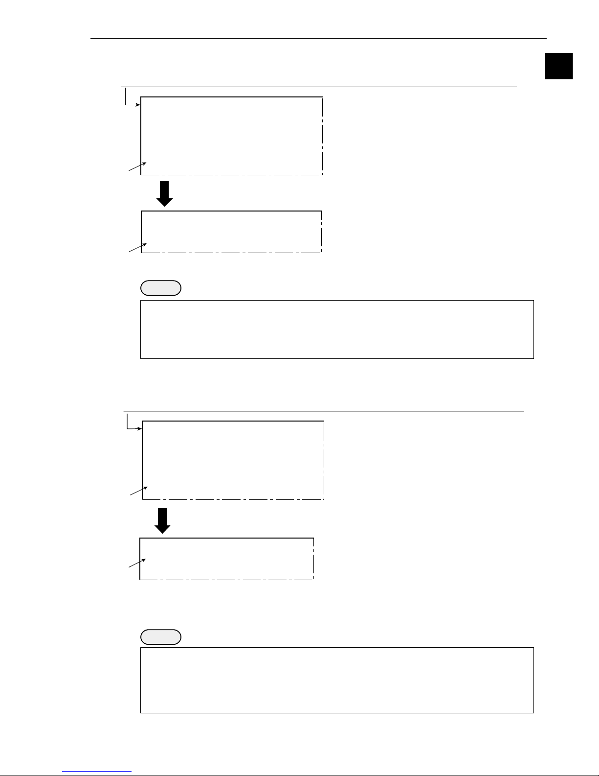
1-2 Method for selecting the menu configuration
(1) When power is first turned ON after the machine is delivered
When power is first turned ON after the machine is delivered, the [SELECT MENU] screen will
appear.
- For details about the method for using the simplified menus, see the IV-S30 User’s Manual
(Introduction and Hardware).
Notes
- If you have saved the configuration data in flash memory by selecting the "SAVE" item, the
next time you turn ON the power, the MAIN OPS MENU you selected will be displayed
automatically.
1 To select the standard menus
configuration
1. Move the cursor to the [
1
STANDARD
MENU] item with the up and down
keys, and press the SET key.
- The standard mode [MAIN OPS
MENU] screen will appear.
2 To select the simplified menus configuration
1. Move the cursor to the [2SIMPLIFIED
MENU] item with the up and down keys,
and press the SET key.
- The [SIMPLIFIED MENU] screen will
appear.
[SELECT MENU]
1STANDARD MENU (STD RUN-MENU)
2SIMPLIFIED MENU (SEL EASY MENU)
[SIMPLIFIED MENU]
1MEAS OBJ POSITIONING EXISTENCE
2
SELECT CAMERA
CAM1 CAM1&2
3
XY CORRECTION
NO YES
OPS-MENU
Power ON
[SIMPLIFIED MENU]
[SELECT MENU]
T.IMG C1 L
VX.X
(TYPE00)
MEAS 0000ms 2000-08-01 10:30
MEASURE 0 CAM1 NO
CHG-MEA CHG-REG CHG-RST CHG-C1 CHG-C2 CHG-EVAL CUSTOM-MNU
OPS-CND MEA-CND SYS-CND CHG-TYPE NG-IMG-DSP NEXT-NG MANL-MEAS
X0~7 Y0~7 READY
Page 14
1-3
Setting and Operating Outline
1
1. Move the cursor to the "2SIMPLIFIED MENU"
item with the up and down keys, and press the
SET key.
- The [SIMPLIFIED MENU] screen will
appear.
2. As described on the previous page, select each
item that you want to specify, and press the
SET key.
[SELECT MENU]
1STANDARD MENU (STD RUN-MENU)
2SIMPLIFIED MENU (SEL EASY MENU)
1. Move the cursor to the "5STD → SELECT
MENU" item on the [SYSTEM COND] menu,
and press the SET key.
2. Select the "EXEC" item, and press the SET
key. The [SELECT MENU] screen will appear.
Move the cursor to the "SYS-CND" item on the MAIN OPS MENU screen, and press the SET key.
[SYSTEM COND]
1
I/O CONDITIONS
(TO NEXT SUB-MENU)
2COMM.SET (TO NEXT SUB-MENU)
3
COMPUTER LINK
(TO NEXT SUB-MENU)
4INITIALIZATION ALL-INIT INIT-RAM
5
STD→SELECT MENU
EXEC
1. Move the cursor to the "5SIMPLE MENU →
STD" item on the [SYSTEM COND] menu, and
press the SET key.
2. Select the "EXEC" item, and press the SET key.
The [SELECT MENU] screen will appear.
Move the cursor to the "SYS-CND" item on the MAIN OPS MENU screen, and press the SET key.
[SYSTEM COND]
1SERIAL OUTPUT NO PC-LINK SERIAL
2COMM.SET
(TO NEXT SUB-MENU)
3
COMPUTER LINK
(TO NEXT SUB-MENU)
4INITIALIZATION ALL-INIT INIT-RAM
5
SIMPLE MENU→STD
EXEC
1. Move the cursor to the "1STANDARD MENU"
item with the up and down keys, and press the SET
key.
- The [MAIN OPS MENU] screen with the
standard menus will appear.
[SELECT MENU]
1STANDARD MENU (STD RUN-MENU)
2SIMPLIFIED MENU (SEL EASY MENU)
(2) Changing the screen from the standard menus to the simplified menus configuration
Notes
- Make sure to SAVE the system configuration data after you change from the standard menus
to the simplified menus configuration. Otherwise, your selection of the simplified menus
configuration will be ignored the next time you turn ON the power.
- When you change the IV-S30 configuration from the standard menus to the simplified menus,
the data will be saved into the RAM.
(3) Changing from the simplified menus to the standard menus configuration
To select whether "POSITIONING" or "EXISTENCE" is displayed on the simplified menus, select the
[2 SIMPLIFIED MENU] item on the [SELECT MENU] screen, and specify each item you want to
appear on the simplified menus.
Notes
- Make sure to SAVE the system configuration data after you change from the simplified menus
to standard menus configuration. Otherwise, your selection of the standard menus
configuration will be ignored the next time you turn ON the power.
- The items that you selected for display on the simplified menus will be saved when the screen
configuration is changed to the standard menus.
Page 15

1-4
Setting and Operating Outline
1
1-3 Screen specifications
[1] Operation (run) screen
After selecting the "STANDARD MENU" and save it (see page 1-2), supply power to the controller (IVS31M/S32M/S33M), and the MAIN OPS MENU (startup screen) will be displayed on the monitor.
- Before applying the power, make sure that the power cable, monitor cable, camera cables, and
remote key pad have been connected to the controller.
2 The results of the programmable output (auxiliary relay C116) are displayed.
If C116 has not been set, the results of C112 are output. - See page 16-8
3 T C1 L æ
Display
OK
NG
"OK" is displayed when all of the individual evaluation results are acceptable.
"NG" is displayed if any single evaluation result is unacceptable.
(Error
message)
Description
4 LOCK FULL VX.X Ë
5 C1= 002.2 OK
- This item is displayed when the light level monitor "MNTR LIGHT LVL" on the
[OBJECT TYPE SYS.] menu has been set to "YES." - See page 3-31
6 Measurement No. (0 to 4), camera No. (1 or 2) and measurement program name
Average light level and judgment result (OK/NG)
Camera No. (C1 = camera 1, C2 = camera 2)
Flashes during communications
System program version number
Image capture modes (Fixed "FULL" for the IV-S31M/S32M):
FULL = full, HALF = half, F+H = Full + half.
Run menu is locked ("LOCK" is not displayed when the screen is unlocked.)
An error code and the measurement number that caused the error are
displayed on the upper line. The error message is displayed on the lower line.
Operation status display: ○ flashing = running,
Image brightness: H = Original brightness of captured image
L = Brightness reduced to half that in the captured image
Output monitor status: C1 = Camera 1, C2 = Camera 2, C1/C2 = Camera 1 & 2
NG = NG image, C1/NG = Camera 1 & NG image
Image display mode: F = Freeze mode, T = Through mode (raw images),
N = No camera input (To change between F and T
modes, press the SEL key.)
(1) MAIN OPS MENU screen
- To display a dynamic image on the MAIN OPS MENU, set the through image function to "Yes." -
See page 2-10.
T.IMG C1 L
LOCK FULL VX.X
C1=002.2 OK
C2=100.0 OK
NG IMG 0(X)
(TYPE00)AREA1
OK
MEAS XXXXms 2000-08-01 10:30
MEASURE 0 CAM1 POSI-DEVIATION
CHG-MEA CHG-REG CHG-RST CHG-C1 CHG-C2 CHG-EVAL CUSTOM-MNU
OPS-CND MEA-CND SYS-CND CHG-TYPE NG-IMG-DSP NEXT-NG MANL-MEAS
X0~7 Y0~7 READY
Display measurment
result for each
measurement
program
1
2
8
9
7
3
4
5
0
6
1 Object type No. ((IV-S33M: 00 to 63, IV-S32M: 00 to 31, IV-S31M: 00 to 15) and the name assigned by
the user for each object type.
Page 16

1-5
Setting and Operating Outline
1
7 Menu bar
*1: These functions are displayed and can be used when an IV-S32M/S33M is being used.
8 The screen shows the total measurement time which is determined by the following times (from
measurement start to measurement end).
In order to speed up the measuring time, 1 increase the shutter speed, 2 select partial capture of
the CCD image, and 3 set NO for each of the result displays (message display, pattern display).
When the IV-S33M is used, you can also 4 use a high-speed camera, and 5) select the half
mode.
When the IV-S32M/S33M is used, the date and time are displayed on the screen.
[E.g.] 2000-10-01 10:30 - 10:30 October 1, 2000
CCD exposure time
(Shutter speed)
CCD image
capture time
Measurement result
display time
Actual measurement time
Input I/F = Monitor display measurement time
with serial/CCD trigger
Input I/F = Monitor display measurement time with parallel input
Type change
time
(Only when changing type)
Image
processing time
Serial output time
rabuneM noitpircseD
AEM-GHC
-erusaem(
egnahctnem
ehtforedroehtnihguorhtdelcycebnacstlusernoitaulavefoyalpsidehT
.syeknwoddnapuehtgnisusrebmuntnemerusaem
1MAC0ERUSAEM( → 2MAC0ERUSAEM → 1TNEMERUSAEM →
2TNEMERUSAEM → 3TNEMERUSAEM → )4TNEMERUSAEM
GER-GHC
noitartsiger(
)egnahc
delcycebnacstlusernoitaluclaclaciremun/stlusertnemerusaemehtfoyalpsidehT
gnisumargorptnemerusaemehtnisrebmunnoitartsigerehtforedroehtnihguorht
.syeknwoddnapueht
TSR-GHC
:syeknwoddnapuehtsserp,ecneuqesgniwollofehtniyalpsidehtegnahcoT
stlusermargorptnemerusaeM" → stnemerusaemelgnadnaecnatsid → ciremun
".snoitaluclac
stnemerusaemelgnadnaecnatsidehtgnisusmargorptnemerusaemehT-
,tnemerusaemhctamfoeergedeht,tnemerusaemnoitaivednoitisopehtera
noitisopelpitlum)ytivargforetnec(,noisrevnocyranibretfanoitacifitneditcejbo
.snoitcepsnihctamfoeergedelpitlumdna,stnemerusaem
1C-GHC
.syeknwoddnapuehtgnisunwod/pusaremacowtehtmorfsegamitilpsehtllorcS
otpotmorfdellorcsebnacneercseht,wolebdnaevobatilpssineercsehtnehW(
llorcslliwneercseht,thgirdnatfeltilpssineercsehtnehW.pototmttobromottob
).tfelotthgirrothgirottfelmorf
ehtnoGMI-GN&1MACro2&1MACtcelesuoynehwdesuebnacnoitcnufsihT
(.meti"TUPTUOROTINOM" - )2-2egap
2C-GHC
)GNegnahc(
LAVE-GHC
.syeknwoddnapuehtgnisserpybrehtonaotneercsnoitarepoenomorfevoM
UNEMSPONIAM" → EGNAHCDNOCNOITAULAVE → ROTINOMCP →"
(.meti"YALPSIDUNEMSPO"ehtno"SEYNIAM"tceleS- - )01-2egap
NOITAULAVAE"",UNEMSPONIAM"ehtgnisurofsdohtemehttuobasliatedroF-
.91-61segapees,neercs"rotinomCP"dna",EGNAHCDNOC
neercsEGNAHCDNOCNOITAULAVEehtelihwyekTESehtsserpuoyfI-
.egnahcotmetiehtotevomlliwrosruceht,deyalpsidsi
UNM-MOTSUC .)unembus("UNEMMOTSUC"ehtpugnirbotyekTESehtsserP
DNC-SPO
(.)unembus("DNOCNUREPYT"ehtpugnirbotyekTESehtsserP - ot1-2egap
)31-2
DNC-AEM .)unembus(unem"DNOCSAEMEPYT"ehtpugnirbotyekTESehtsserP
DNC-SYS
sunem"SNOITIDNOCO/I"dna"DNOCMETSYS"ehtpugnirbotyekTESehtsserP
.)sunembus(
EPYT-GHC
.syeknwoddnapuehtgnisu)36ot0(rebmunepyttcejboehtegnahC
otmeti"GNHCEPYTLNAM"ehtgnittesybyllaunamdegnahcebnacrebmunehT
.unem"SNOITIDNOCO/I"ehtno"SEY" - 41-2egap
PSD-GMI-GN
.neercsyalpsidegamiGNehtotevomotyekTESehtsserP - .12-1,7-1egaP
.neercssihtotegnahctonlliwyalpsideht,deretsigertonsiegamiGNehtnehW-
GN-TXEN
dnapuehtgnisurebmunderetsigeregnahcdnasegamiGNderetsigerehtyalpsiD
.syeknwod
SAEM-LNAM
owtynaneewtebsecnatsidehterusaemotyllaunamsrosrucriahssorcowtehtevoM
sexaYdnaXehtnostniop
.meti"1.CNUFNOISNETXE"ehtno"SAEM-LNAM"tceleS- - 21-2egap
*1
Page 17

1-6
Setting and Operating Outline
1
0 With the IV-S32M/S33M, the NG image number and the total number of NG images registered
are both displayed.
- To display these, select "YES" for the NG image registration. (Each object type) - Page 3-36
- The NG image register No. can be changed using the menu bar.
ËË
ËË
Ë Image display area
The size of the area where the image is displayed on the monitor is 512 pixels (horizontal) × 480
pixels (vertical).
ËË
ËË
Ë Evaluation condition change screen
On the MAIN OPS MENU screen (page1-4), select the "CHG-EVAL" item on the menu bar. You
can display the evaluation condition change menu by pressing the up and down keys (see the
previous page).
- Press the SET key. The cursor will move to the area containing the phrase "evaluation condition
change menu during operation." You can change the settings for the evaluation conditions.
- At this time, the screen display will look the same as the normal MAIN OPS MENU, except for
the area marked "evaluation condition change menu shown during operation."
X axis
512
480
Y axis
Origin (0, 0)
(511, 479)
(Unit: pixels)
T.IMG C1 L
LOCK FULL VX.X
C1=002.2 OK
C2=100.0 OK
NG IMG 0(X)
(TYPE00)AREA1
OK
MEAS XXXXms 2000-08-01 10:30
MEASURE 0 CAM1 POSI-DEVIATION
CHG-MEA CHG-REG CHG-RST CHG-C1 CHG-C2 CHG-EVAL CUSTOM-MNU
OPS-CND MEA-CND SYS-CND CHG-TYPE NG-IMG-DSP NEXT-NG MANL-MEAS
X0~7 Y0~7 READY
Display evaluation
condition change
menu while in
operation
(Screen on the IV-S33M)
9 Display the measured results for each mesurement program
- If you save*2 the set conditions, "measured result screen" and "Image brightness: H/L" on the
MAIN OPS MENU (operation screen), your settings will be restored whenever the power is
turend ON.
*2 To save the data, enter the "SAVE" item on the [TYPE RUN COND], [TYPE MEAS COND],
or [SYSTEM COND] menus.
Page 18

1-7
Setting and Operating Outline
1
(2) NG image display screen (IV-S32M/S33M)
When the IV-S32M/S33M is used, move the cursor to the menu bar "NG-IMG-DSP" on the MAIN
OPS MENU (page 1-4), and press the SET key. The screen will change to the NG image display
screen. When the measuring stops, you can see the NG images already registered.
- To display the NG image while measuring, see "Displaying NG images on the MAIN OPS menu".
- See 1-18.
Note: Please do the following to display NG images on the screen.
1. Before entering this screen, you must set the "1REGST NG IMG" on the [OBJECT TYPE
SYS] to "YES."
2. Change the image display in the upper right of the screen to "F.IMG" (static image) by
pressing the SEL key. - See 1-17.
3. NOTE WELL that while an NG image is being displayed, the IV-S30 cannot start another
set of measurements.
- For details about the menu bar on the screen above. - See page 1-21.
F.IMG C1 L
FULL VX.X
NG.IMG 0(X)
2000-08-01 10:25
(TYPE00)AREA1
OK
MEAS XXXXms 2000-08-01 10:30
MEASURE 0 CAM1 POSI-DEVIATION
X0~7 Y0~7 READY
Display measurment
result for each
measurement
program
CHG-MEA CHG-REG CHG-EVAL NEXT-NG RE-EXAM DEL NG DEL ALL N
OPS-MENU
Page 19

1-8
Setting and Operating Outline
1
[2] Menu configuration
*1 You can return to the MAIN OPS MENU from any menu screen in the 2nd or 3rd layer.
*2 You can directly access the evaluation conditions from the image setting conditions, such as the
gray scale search, edge inspection, and binary area conditions.
*3 The measurement programs that can execute a distance and angle measurement are as follows:
Positional deviation measurement, degree of match measurement, and object identification by
binary conversion (center of gravity), multiple position measurement, multiple degree of match
inspection.
- The numbers shown inside parentheses are reference page numbers.
- For the details about the simplified menu configuration, see the "IV-S30 User’s Manual (Introduction
and Hardware)."
[GRAY-SCALE COND]
(4-3 etc.) *2
[EDGE DETECT COND]
(4-4 etc.) *2
[BINARY AREA COND]
(8-3 etc.) *2
[EVALUATION COND]
(3-16)
(including serial output settings)
[DISTANCE&ANGLE COND]
(Chapter 14) *3
[NUMERIC CALC COND]
(15-2)
[OUTPUT COND] (16-3)
[FINAL CALC COND] (15-10)
[FINAL OUTPUT COND] (16-11)
[CCD TRIGGER COND]
(17-18)
[LIGHT LEVEL COND] (3-31)
First layer
(MAIN OPS MENU)
MAIN OPS MENU
(1-4)
EVALUATION
COND CHANGE
(1-6)
PC MONITOR
(16-19)
NG-IMAG-DISP
(1-21)
Second layer
(Upper and lower, two window style)
Upper screen
[SYSTEM COND] (1-13, 2-14)
1I/O CONDITIONS
2COMM. SET
3COMPUTER LINK
4INITIALIZATION (2-15)
5STD → SELECT MENU (1-3)
6SELF-DIAGNOSIS (2-16)
7GAIN-OFFSET
8TIME(2-17)
9CAMERA TYPE(2-19)
[TYPE RUN COND](2-1 to 2-13)
[TYPE MEAS COND] (3-1)
1OBJECT TYPE NO.
2SELECT CAMERA
3IMG PRE-PROCESS
3MEASURE 0 CAM1
4MEASURE 0 CAM2
5MEASUREMENT 1
6MEASUREMENT 2
7MEASUREMENT 3
8MEASUREMENT 4
TITLE etc.
Lower screen
[I/O CONDITIONS] (17-1)
[SET COM PARM] (17-19)
[COMPUTER LINK] (17-20)
[GAIN-OFFSET] (2-18)
[IMG PRE-PROCESS]
[MEASUREMENT 0 CAMERA 1]
(1-11)
1MEAS SELECTION
2COMPARE IMGS (3-23)
3CHNG LIGHT LEBEL (3-14)
4SPACE FILTER (3-10)
[TYPE MEAS COND]
[POSITION CORRECTION] (3-26)
[MEASUREMENT 0 CAMERA 2]
(The items displayed are the same
as for MEASURE 0 CAM 1.)
[MEASUREMENT 1] (1-11)
1MEAS SELECTION
2SELECT CAMERA
3CHNG LIGHT LEBEL (3-14)
4SPACE FILTER (3-10)
[TYPE MEAS COND]
[MEASUREMENT 2 to 4]
(The items displayed are the same as for
MEASUREMENT1.)
[TITLE registration] (3-30)
[I/O for each object type] (3-33)
1TRIG CCD START (17-17)
2CCD TRIG COND
3SHUTTER SPEED (3-33)
4SERIAL OUTPUT (17-21 to 24)
5SET SERIAL BLOCK (17-22)
[SYSTEM for each object type] (3-34)
1REGST NG IMG (3-36)
2HALT ON NG MEAS (3-37)
3MNTR LIGHT LVL (3-31)
4LIGHT LVL COND
5COPY (3-34)
6INITIALIZATION (3-35)
7WINDOW PACKAGE MOVE (3-38)
Third layer
*1
*1
[ADJ.IMG GRAY] (3-18)
[MASK BINARY IMG] (3-19)
[COMPARE IMGS] (3-23)
Page 20

1-9
Setting and Operating Outline
1
[3] Configuration of the setting conditions
Positional deviation
measurement
Operating
conditions
System
conditions
Object
type 00
Object
type 00
Object
type 01
Object
type 63
Measuring
conditions
Object
type 01
Object
type 63
Measurement 0,
camera 1
Measurement 0,
camera 2
Measurement 1
Measurement 2
Measurement 3
Measurement 4
Same as "object type 00."
Same for "Measurement 00."
Camera
1 and 2
Camera 1
and NG
images
Image pre-
processing (3-17)
Input and output for
each object type
System for
each object
-
The numbers in parenthesies ( ) are page numbers for your reference.
Output monitor (2-2), image capture (2-4), message display (2-5), pattern
display (2-6), binary image display (2-7), θ angle correction, image display
(2-8), display operation screen (2-9), through display (2-10), extension
function 1 (2-11), extension function 2 (2-12).
- I/O conditions (17-1)
Measurement start input I/F, parallel input X6, parallel input X7, strobe output,
object type manual change (2-14)
- Communication setting (17-19)
Communication standard, communication speed, data length, parity, stop bit,
station number
- Computer link (17-20)
Manufacturer, station number, top line of the written results
- Initialization (2-15), self-diagnosis (2-16), gain/offset (2-18), system time (2-17)
- Menu selection (1-2)
Standard menu / Simplified menu
- Camera setting (2-19)
Camera selection, image capture mode
Measuring program
Same for Camera 1 and 2. However,
"Measurement 0, Camera 2" is not
available.
Positional deviation measurement, degree
of match inspection, lead inspection,
BGA/CSP inspection, area measurement
by binary conversion, object counting by
binary conversion, object identification by
binary conversion, point measurement,
multiple positions measurement, multiple
degree of match inspection.
CCD trigger (17-17), shutter speed (3-33), serial
output (17-22 to 23)
Register NG images (3-36), stop NG measurement
(3-37), monitor light level (3-31), copying (3-34),
initialization (3-35), move whole window at one time
(3-38)
-See Chapter 4
See
Chapters
4 to 14.
Page 21

1-10
Setting and Operating Outline
1
1-4 Setting the measurement programs
To execute a specific measurement program (positional deviation measurement, degree of match
inspection, etc.), select MEASUREMENT 0 to 4 on the "TYPE MEAS COND" menu.
- MEASUREMENT 0 only allows you to measure positional deviation.
- For details about the settings for each measurement program, see Chapters 4 to 14.
- Specify the conditions for distance and angle measurement in the positional deviation measurement,
the degree of match inspection, object identification by binary conversion (MEAS GRAV CENTR: YES),
multiple position measurement, and for multiple degree of match inspection.
MAIN OPS MENU screen (See page 1-4.)
T.IMG C1 L
VX.X
NG IMGS 0( 0)
(TYPE00)
MEAS 0000ms 1999-07-09 14:48
MEASURE 0 CAM1 NO
X0~7 X0~7 READY
To the next page
CHG-MEA CHG-REG CHG-RST CHG-C1 CHG-C2 CHG-EVAL CUSTOM-MNU
OPS-CND MEA-CND SYS-CND CHG-TYPE NEXT-NG RE-EXAM-NG MANL-MEAS
Move the cursor to the "MEA-CND" item using the left and right keys,
and press the SET key.
1. Move the cursor to item 1 us-
ing the left and right keys.
2. Select the object type No. (0 to
63) that you want using the up
and down keys.*
3. Move the cursor to "YES" using
the left and right keys.
- Items 2 to 8 shown on the
next page will be displayed.
A "X" mark will change to "O"
when a corresponding object
type is registered from No. (*).
[TYPE MEAS COND]
[OBJCT REG.LIST]
①
OBJECT TYPE NO. 00(0~63) NO YES
OPS-MENU SAVE LOCK TITLE FINAL-CALC FINAL-OUTPUT I/O SYSTEM
00 01 02 03 04 05 06 07 08 09 10 11 12 13 14 15
××××××××××××××××
16 17 18 19 20 21 22 23 24 25 26 27 28 29 30 31
××××××××××××××××
1
2
3
32 33 34 35 36 37 38 39 40 41 42 43 44 45 46 47
××××××××××××××××
48 49 50 51 52 53 54 55 56 57 58 59 60 61 62 63
××××××××××××××××
←
*Object type No.
IV-S33M: 00 to 63
IV-S32M: 00 to 31
IV-S31M: 00 to 15
Page 22

1-11
Setting and Operating Outline
1
To chapter 4 to 14
1MEAS SELECTION
NO POSI-DEVIATION CHK-DEG-MATCH
INSPECT-LEAD INSPECT-BGA/CSP
MEAS-BIN-AREA CNT-BIN-OBJ LABEL-BIN-OBJ
POINT-MEAS MULTI-POSI MULTI-MATCHES
2SELECT CAMERA CAM1 CAM2
3CHNG GRAY LEBEL NO YES(00.0TIMES
γ+ γ -
CHNG-L
INCRS-M
)
4SPACE FILTER
NO NUM-OF-TIMES 0(0~5)
From the previous page
When you want to specify MEASUREMENT 0 (CAM1/2)
- The only measurement program available in this mode is "POSI-DEVIATION"
1. Select item 4 or 5 using the
up and down keys.
2. Select "NO" using the left and
right keys.
3. Select item 1 on the lower
half of the screen, and press
the SET key.
4. Select the "POS-DEVIATION"
item using the left and right
keys, and press the SET key.
- "NO" in item 4 or 5 will
change to "POSDEVIATION."
When you want to choose any of MEASUREMENT 1 to 4.
- You can select from 10 measurement programs.
1. Select item 6, 7, 8, or 9
using the up and down keys.
2. Select "NO" using the left and right
keys.
3. Select item 1 on the lower half of
the screen, and press the SET
key.
4. Select the measurement program
that you want to use using the left
and right keys, and press the SET
key.
- The "NO" in item 6, 7, 8, or
9 will change to the measure-
ment program that you have
set.
1
3
4
2
[TYPE MEAS COND]
[MEAS 0 CAM1 COND]
1OBJECT TYPE NO.
00(0~63) NO YES
2SELECT CAMERA CAM1&2 CAM1&NG-IMG
3IMG PRE-PROCESS
(TO NEXT SUB-MENU)
4MEASURE 0 CAM1 NO (MEAS-COND) NO
5MEASURE 0 CAM2 NO (MEAS-COND) NO
6MEASUREMENT 1
NO (MEAS-COND)
7MEASUREMENT 2
NO (MEAS-COND)
8MEASUREMENT 3
NO (MEAS-COND)
9MEASUREMENT 4
NO (MEAS-COND)
1MEAS SELECTION NO POSI-DEVIATION
2COMPARE IMGS NO
3CHNG GRAY LEBEL NO YES(00.0TIMES
γ+ γ -
CHNG-L
INCRS-M
)
4SPACE FILTER
NO NUM-OF-TIMES 0(0~5)
OPS-MENU SAVE LOCK TITLE FINAL-CALC FINAL-OUTPUT I/O SYSTEM
OPS-MENU RETURN LOCK
[TYPE MEAS COND]
[MEASUREMENT 1]
1OBJECT TYPE NO.
00(0~63) NO YES
2SELECT CAMERA CAM1&2 CAM1&NG-IMG
3IMG PRE-PROCESS
(TO NEXT SUB-MENU)
4MEASURE 0 CAM1 NO (MEAS-COND) NO
5MEASURE 0 CAM2 NO (MEAS-COND) NO
6MEASUREMENT 1
NO (MEAS-COND)
7MEASUREMENT 2
NO (MEAS-COND)
8MEASUREMENT 3
NO (MEAS-COND)
9MEASUREMENT 4
NO (MEAS-COND)
OPS-MENU SAVE LOCK TITLE FINAL-CALC FINAL-OUTPUT I/O SYSTEM
OPS-MENU RETURN LOCK
1
3
2
4
*
*
(Two positions marked)
When "CAM1&NG-IMG"
is selected for "2
SELECT CAMERA," the
display will be different.
- See page 3-3.
Displayed when the IV-S32M/S33M
is used.
Page 23

1-12
Setting and Operating Outline
1
1-5 Common operations for each menu
[1] Operations to return to the MAIN OPS MENU
You can let the screen return to the MAIN OPS MENU at one operation from any menu screen.
ËË
ËË
Ë Menu display
[TYPE RUN COND] menu
ËË
ËË
Ë Operation details
Move the cursor to the "OPS-MENU" item using the up/down and left/right keys. Then press the SET
key. The screen will return to the "MAIN OPS MENU."
[2] Saving data
All of the data such as measurement and evaluation conditions entered on the "TYPE RUN COND,"
"TYPE MEAS COND," and "SYSTEM COND" menus, can be saved into the IV-S30 flash memory.
ËË
ËË
Ë Operation procedure
[SYSTEM COND] menu
1. On each menu screen, move the cursor to "SAVE" using the up/down and left/right keys, and
press the SET key.
- The following message will be displayed on the lower part of the screen.
DATA SAVE? (Do you want to save the data?) (YES=[SET]/NO=[ESC])
2. Press the SET key.
- The IV-S30 will start saving the data and the progress will be displayed on the bottom of the
screen.
When the data has been saved in the IV-S30 flash memory, the display will change from
"SAVING" to "COMPLETE SAVE."
REFERENCE IMG
SYSTEM I/O
OBJECT TYPE COND
■■
■
■■■■■■■■■■■□□□□□
SAVING
1MONITOR OUTPUT CAM1 CAM2 CAM1&2 (HORIZ VERT)
2CAPTURE IMG PARTIAL-IMG WHOLE-IMG NO
0EXTENSION FUNC.2 NO DISPLAY+CURSOR(1 2)(000,000)
[TYPE RUN COND]
OPS-MENU SAVE LOCK
[SYSTEM COND]
1I/O CONDITIONS (TO NEXT SUB-MENU)
2COMM.SET (TO NEXT SUB-MENU)
9CAMERA TYPE (TO NEXT SUB-MENU)
OPS-MENU SAVE LOCK
Displayed when the IV-S32M/S33M
is used.
Page 24

1-13
Setting and Operating Outline
1
[3] Lock the menu display
You can select whether or not to display menus on each of the menu screen.
Select the "LOCK" item on each menu screen to change the settings.
ËË
ËË
Ë Operating procedure
"SYSTEM COND" menu
1. Move the cursor to "LOCK" using the up/down and left/right keys, and press the SET key.
- The screen for selecting whether or not to display each of the menus will appear.
2. Move the cursor to the item that you want to change using the up and down keys, and press the
SET key.
3. Select "YES" or "NO" using the up and down keys.
4. Repeat the steps 2 and 3 to change other menus.
5. Select the "RETURN" item using the up/down and left/right keys, and press the SET key.
- Items that are set to "NO" will not appear on the screen.
- The screen on the left will be
shown when "NO" is selected
for menus 5 to 7 on the
menu display setting screen.
[SYSTEM COND]
1I/O CONDITIONS (TO NEXT SUB-MENU)
2COMM.SET (TO NEXT SUB-MENU)
3COMPUTER LINK
(TO NEXT SUB-MENU)
4INITIALIZATION ALL-INIT INIT-RAM NG-IMG-INIT
5
STD→SELECT MENU
EXEC
6SELF DIAGNOSTICS EXEC
7GAIN-OFFSET (TO NEXT SUB-MENU)
8TIME 2000Y10M16D18H56M
9CAMERA TYPE (TO NEXT SUB-MENU)
OPS-MENU SAVE LOCK
1
Displayed when the IV-S32M/S33M
is used.
Displayed when the IV-S33M is used.
[SYSTEM COND]
1I/O CONDITIONS MENU YES
2COMM.SET MENU YES
3COMPUTER LINK
MENU YES
4INITIALIZATION MENU YES
5STD→SELECT MENU
MENU YES
6SELF DIAGNOSTICS MENU YES
7GAIN-OFFSET MENU YES
8TIME MENU YES
9CAMERA TYPE MENU YES
OPS-MENU SAVE RETURN
5
2
3
[SYSTEM COND]
1I/O CONDITIONS (TO NEXT SUB-MENU)
2COMM.SET (TO NEXT SUB-MENU)
3COMPUTER LINK
(TO NEXT SUB-MENU)
4INITIALIZATION ALL-INIT INIT-RAM NG-IMG-INIT
8TIME 2000Y 10M 16D 18H 56M
9CAMERA TYPE (TO NEXT SUB-MENU)
OPS-MENU SAVE LOCK
Page 25

1-14
Setting and Operating Outline
1
1-6 Power ON setting menu
[1] Operations menu lock
To prevent accidental changes to conditions you have set, the MAIN OPS MENU can be locked so that
the screen cannot be changed to SET-SCRN. The operation can only be carried out on the [POWER ON
SETTING] menu.
ËË
ËË
Ë Display procedure
Follow the procedure described below when turning ON the power to the controller (IV-S31M/S32M/
S33M) , and the [POWER ON SETTING] menu will be displayed on the monitor.
1. Turn ON the power to the IV-S30 controller, while holding down the ESC key.
2. Keep pressing the ESC key down for approx. 9 sec., after turning ON the power and the menu
will be displayed.
ËË
ËË
Ë Operation procedure
1. On the [POWER ON SETTING] menu, move the cursor to item 1MAIN OPS MENU with the up
and down keys, and press the SET key.
2. Move the cursor to UNLOCK or LOCK with the left and right keys, and press the SET key.
3. Move the cursor to item 3OPERATION with the up and down keys, and press the SET key.
Press the SET key once more.
- The IV-S30 saves the settings in the flash memory and the screen will return to the SELECT
MENU.
ËË
ËË
Ë Display when the MAIN OPS MENU is locked
[POWER ON SETTING]
1 MAIN OPS MENU UNLOCK LOCK
2 DISPLAY MODE JAPANESE ENGLISH
3 OPERATION
1MAIN OPS MENU
Description
UNLOCK
LOCK
All of the operating conditions for the
IV-S30 can be changed.
The MAIN OPS MENU is locked and
no change can be made.
"LOCK"willbe
displayedonthe
MAINOPSMENU
T.IMG C1 L
LOCK FULL VX.X
(TYPE00)AREA1
OK
MEAS XXXXms
MEASURE 0 CAM1 POSI-DEVIATION
Page 26

1-15
Setting and Operating Outline
1
[2] Change the Japanese or English display mode
Change disply between Japanese and English. Use the [POWER ON SETTING] menu for the selection.
ËË
ËË
Ë Display procedure
Follow the procedure described below when turning ON the power to the controller(IV-S31M/S32M/
S33M), and the [POWER ON SETTING] menu will be displayed on the monitor.
1. Turn ON the power to the controller, while holding down the ESC key.
2. Keep pressing the ESC key down for approx. 9 sec., and the following menu will be displayed.
ËË
ËË
Ë Operating procedure
3. Move the cursor to item "2DISPLAY MODE" (display mode) with the up and down keys, and
press the SET key.
4. Move the cursor to "JAPANESE" or "ENGLISH" with the left and right keys.
5. Move the cursor to "3OPERATION" using up and down keys and press the SET key. Then,
again press the SET key.
- The screen will change to MAIN OPS MENU.
3
5
4
[POWER ON SETTING]
1MAIN OPS MENU UNLOCK LOCK
2DISPLAY MODE JAPANESE ENGLISH
3OPERATION
Page 27

1-16
Setting and Operating Outline
1
1-7 Remote key pad and specifications
4 Image change key (SEL)
1 Direction keys
(up, down,
left and right)
5 Measurement start/brightness select key
(TRG/BRT)
2 Set (select) key (SET)
3 Cancel key (ESC)
Selecting an item on a menu
screen
Setting a value
Determine the setting value
Switching the image mode
between the through mode
and freeze mode
Start measurement input
Switching the brightness level
(between H and L)
DescriptionFunctionKey name
- Select a digit or an item with the left and right
keys, and then specify a value with the up and
down keys.
- Specify a value with the up, down, right and left
keys.
Switch the image mode between through and
freeze on the setting screen. (See the
preceding page.) When the mode is switched
from through to freeze, a new image is
captured.
Note: The "Gain/offset adjustment" screen is
only displayed in the through mode.
Press this key on the MAIN OPS MENU, and a
new measurement is triggered.
Change the displayed image brightness.
- Use this key when the image is so bright that
characters are difficult to see.
- The brightness can be changed on any
screen other than the run screen.
Direction keys
(up, down, left
and right)
Set (select) key
(SET)
Cancel key
(ESC)
Image change
key (SEL)
Measurement
start/brightness
select key
(TRG/BRT)
1
2
3
4
5
Select an item with the up, down, left and right
keys.
*
* The direction keys have an auto-repeat function
Set each coordinate.Setting a window
Returning a setting to its
original state before being
changed
Returning to the previous
menu
Determine the highlighted item
Page 28

1-17
Setting and Operating Outline
1
metI M13S-VI M23S-VI M33S-VI egapecnerefeR
segamiGNretsigeR
×
71-1
segamiGN
yalpsid
SPONIAM
unem
neercs
nehwyalpsiD
egamiGNna
srucco
02-1ot81-1
yrotsihyalpsiD
×
02-1
neercsyalpsidegamiGN
×
22-1ot12-1
segamiGNezilaitinI
×
22-1
*
*
1-8 Register and display NG images
NG image refers to any image that the controller has determined to be unacceptable after making the
measurements.
- NG images are registered in the controller’s memory. By replaying the NG images, you can review the
points with problems.
This section describes how to register, display, and initialize NG images. Depending on type of the
controller you are using, some settings are not available.
* The left and right split screen display is not available using the monitor output.
[1] How to register NG images (IV-S32M/S33M)
When the IV-S32M/S33M is used, select "YES" for NG image registration. NG images will be registered
in the controller’s memory as they occur.
To make this setting, select 1, "REGST NG-IMG" on the [OBJECT TYPE SYS.] menu.
- See page 3-36.
- Up to 128 NG images can be registered at one time (the NG image numbers are 0 to 127). When 128
NG images are registered, the oldest NG image will be deleted and replaced by the 129th NG image.
(All of numbers assigned to the NG images will de decremented by one.)
The actual total number of NG images that can be registered may less than the 128, depending on
the size of the images registered.
[Limitation] The total number of NG images sizes can only occupy a maximum 8, full-size screens
(1,966,080 pixels: 512 x 480 x 8). The maximum screen size is 512 x 480 pixels.
Example: When the NG image size is 256 x 240 pixels, the controller can register up to 32 images.
(256 x 240 x 32 = 1,966,080)
[TYPE MEAS COND]
[OBJECT TYPE SYS.]
1OBJECT TYPE NO. 00(0~63) NO YES
OPS-MENU SAVE LOCK TITLE FINAL-CALC FINAL-OUTPUT I/O SYSTEM
1REGST NG IMG NO YES
2HALT ON NG MEAS NO YES
*
Page 29

1-18
Setting and Operating Outline
1
[2] How to display NG images
NG images can be displayed on the MAIN OPS MENU and on the NG image display screen (IV-S32M/
S33M).
(1) Displaying NG images on the MAIN OPS menu
An NG image (the latest or any previous NG image) recorded with camera 1 can be displayed on the
monitor while conducting measurements from the MAIN OPS MENU.
- This function only refreshes the NG image if another NG is captured. The screen is not refreshed
with normal image measurement results. Thus, this method is useful for an operation that has a
short cycle time and needs to process another workpiece soon after saving the NG image.
- When the measuring is stopped, NG images can also be displayed on the NG image display screen.
- See page 1-21.
The setting procedures are as follows:
1. Select "CAM1&NG-IMG" from the monitor output.
Select "2SELECT CAMERA", on the [TYPE MEAS COND] menu. - See page 3-3
2. Set the monitor output to "NG-IMG" or "CAM1&NG-IMG."
Select 1, "MONITOR OUTPUT" on the [TYPE RUN COND] menu. - See page 2-3.
ÆÆ
ÆÆ
Æ When the IV-S33M is used
ÆÆ
ÆÆ
Æ When the IV-S32M/S33M is used
[TYPE MEAS COND]
1OBJECT TYPE NO.
00(0~63) NO YES
2SELECT CAMERA CAM1&2 CAM1&NG-IMG
3IMG PRE-PROCESS
(TO NEXT SUB-MENU)
Description
①MONITOR OUTPUT
CAM1
NG-IMG
CAM1&NG-IMG
Display the camera 1 image on the whole screen.
Display the NG image on the whole screen.
Display the camera 1 image on upper half, and the NG image on lower half.
F.IMG NG L
1MONITOR OUTPUT CAM1 NG-IMG CAM1&NG-IMG
2CAPTURE IMG PARTIAL-IMG WHOLE-IMG NO
[TYPE RUN COND]
Page 30

1-19
Setting and Operating Outline
1
C1/NG H
VX.X
(TYPE00)
CHG-MEA CHG-REG CHG-RST CHG-C1 CHG-C2 CHG-EVAL CUSTOM-MNU
OPS-CND MEA-CND SYS-CND CHG-TYPE NG-IMG-DSP NEXT-NG MANL-MEAS
C1/NG H
VX.X
(TYPE00)
CHG-MEA CHG-REG CHG-RST CHG-C1 CHG-C2 CHG-EVAL CUSTOM-MNU
OPS-CND MEA-CND SYS-CND CHG-TYPE NG-IMG-DSP NEXT-NG MANL-MEAS
NG H
VX.X
(TYPE00)
CHG-MEA CHG-REG CHG-RST CHG-C1 CHG-C2 CHG-EVAL CUSTOM-MNU
OPS-CND MEA-CND SYS-CND CHG-TYPE NG-IMG-DSP NEXT-NG MANL-MEAS
- Display example when the monitor output is
set to "CAM1&NG-IMG (HORIZ)."
- Display example when the monitor output is
set to "CAM1&NG-IMG (VERT)."
- Display example when the monitor output is set
to "NG-IMG."
Display
camera1
measured
image
Display
camera1
NG image
Display camera1
measured image
Display camera1 NG
image
Display
camera1
NG image
3. Return to the MAIN OPS MENU (page 1-4) and start making measurements.
Shown below are examples of the NG image display.
ÆÆ
ÆÆ
Æ When the IV-S33M is used
C1/NG H
VX.X
(TYPE00)
CHG-MEA CHG-REG CHG-RST CHG-C1 CHG-C2 CHG-EVAL CUSTOM-MNU
OPS-CND MEA-CND SYS-CND CHG-TYPE NG-IMG-DSP NEXT-NG MANL-MEAS
NG H
VX.X
(TYPE00)
CHG-MEA CHG-REG CHG-RST CHG-C1 CHG-C2 CHG-EVAL CUSTOM-MNU
OPS-CND MEA-CND SYS-CND CHG-TYPE NG-IMG-DSP NEXT-NG MANL-MEAS
- Display example when the monitor output is
set to "CAM1&NG-IMG."
- Display example when the monitor output is set
to "NG-IMG."
Display
camera1
measured
image
Display
camera1
NG image
Display
camera1
NG image
When the IV-S32M is used
When the IV-S32M is used
Æ Æ
Æ Æ
Æ When the IV-S31M/32M is used
Page 31

1-20
Setting and Operating Outline
1
NG2
NG6
OK1 NG2 OK3 OK4 OK5 NG6 OK7 OK8 OK9
Measured
image from
Camera 1
NG image
from
Camera 1
OK4 image
NG6 image
OK7 image
NG2 image
Refreshes to NG6 image
Camera 1
capturing
image
Camera 1
NG image
- When a maximum of 10 NG images is registered.
Display NG
image
history
NG image number 9
Measured
image from
camera 1
Up key
Down key
NG image number 10
Up key
Down key
NG image number 0
ËË
ËË
Ë Display when an NG image is captured
The controller automatically refreshes the NG image each time a new NG image is captured.
[An example of the split screen display (above and below)]
ËË
ËË
Ë Display history of NG images (IV-S32M/S33M)
When the IV-S32M/S33M is used, move the cursor to the menu bar "NG-IMG-DISP" on the MAIN OPS
MENU, using the left and right key. Press the up and down keys to display previous NG images.
[An example of scrolling the split screen display (above and below)]
When a new NG image is captured while displaying the history, it will be added to the history.
Note
- When "PARTIAL-IMG" is selected for image capturing (page 2-4), the NG images stored have
the maximum rectangular area set in measurements 0 to 4.
- When "CAM1&NG-IMG" is selected for the monitor output, only one camera* can be used for
each measurement (0 to 4) and for image pre-processing.
* The camera connected to the camera 1 connector (CAMERA 1).
Page 32

1-21
Setting and Operating Outline
1
(2) Displaying images on the NG image display screen(IV-S32M/S33M)
When the IV-S32M/S33M is used, move the cursor to the menu bar "NG-IMG-DISP" on the MIN OPS
MENU (page1-4) and press the SET key. The screen will change to the NG image display. When the
measurement stops, the NG image will be displayed.
- To display NG images while measuring, display them on the MAIN OPS MENU. - See page 1-18.
Note: Please be aware of the following.
1. Change the image display mode in the upper right of the screen to "F.IMG" (static image) by
pressing the SET key.
2. NOTE WELL that while an NG image is being displayed on the NG image display screen,
you cannot measure objects.
1 Display the NG image number and the number of NG images that have been registered.
The NG image number can be selected by selecting "NEXT-NG" on the menu bar.
2 Displays the date and time the NG image was captured.
Example: 2000-10-01 10:25 - October 1st, 2000, AM10:25.
3 Menu bar
NG.IMG 0(X)
2000-08-01 10:25
(TYPE00)AREA1
OK
MEAS XXXXms 2000-08-01 10:30
MEASURE 0 CAM1 POSI-DEVIATION
CHG-MEA CHG-REG CHG-EVAL NEXT-NG RE-EXAM DEL NG DEL ALL N
OPS-MENU
X0~7 Y0~7 READY
Display measurment
result for each
measurement
program
1
2
3
F.IMG C1 L
FULL VX.X
rabuneM sliateD
AEM-GHC
egnahc(
)tnemerusaem
tnemerusaemehtrofyalpsidtlusernoitaulaveehtegnahC
.syeknwoddnapuehtgnisusrebmun
1AREMAC0ERUSAEM( → 2AREMAC0ERUSAEM →
1TNEMERUSAEM → 2TNEMERUSAEM → 3TNEMERUSAEM →
4TNEMERUSAEM →)
GER-GHC
)retsigeregnahc(
srebmunderetsigerehtfoyalpsidtlusertnemerusaemehtegnahC
.syeknwoddnapuehtgnisumargorptnemerusaemehtni
LAVE-GHC
noitaulaveegnahc(
)tluser
yalpsiD".syeknwoddnapuehtgnisuunemnoitarepoehtegnahC
"egamiGN → snoitidnocnoitaulaveegnahc → 01-2egaP
".SEY"ottesebtsumyalpsidneercsgnitarepoehT-
- .01-2egapeeS
,neercsegnahcnoitidnocnoitaulaveehttuobanoitamrofniroF-
.6-1egapees
.yekTESehtsserp,neercsegnahcnoitidnocnoitaulaveehtnO-
.neercsegnahcgnittesehtotevomlliwrosrucehT
GN-TXEN
)egamiGNegnahc(
deyalpsidgniebegamiGNehtrofrebmunderetsigerehtegnahC
.syeknwoddnapuehtgnisu - .egaptxenehteeS
MAXE-ER
)yalper(
htiwdetcelesegamiGNehtnoedamstnemerusaemehtyalpeR
.yekTESehtgnisserpyb,"GN-TXEN"
GNLED
)egamiGNeteled(
"GN-TXEN"htiwdetcelesegamiGNehtylnO.yekTESehtsserP
.deteledeblliw
eteled(NLLALED
)segamiGNlla
.deteledeblliwsegamiGNderetsigerehtllA.yekTESehtsserP
UNEM-SPO
UNEMSPONIAMehtotnruterlliwneercseht,yekTESehtsserP
.neercs
4 When “CAM1&2” is selected on the “4MONITOR OUTPUT” line (TYPE RUN COND menu), the
camera numbers (camera 1: C1, camera 2: C2) will be displayed on the screen next to the
images from those cameras.
Page 33

1-22
Setting and Operating Outline
1
- When 5 NG images are registered.
Up key
Down key
Up key
Down key
NG image number
4
NG image number
5
NG image number
0
ËË
ËË
Ë Display of the Change NG image operation
Note
- When "PARTIAL-IMG" is selected for the image capturing mode (page 2-5), the stored NG
images have the maximum rectangular area set by measurements 0 to 4.
[3] Initializing the NG images (IV-S32M/S33M)
When the IV-S32M/S33M is used, NG images can be initialized with any of the following methods:
1. Item 1, "4INITIALIZATION", on the [SYSTEM COND] menu, will execute an "NG-IMG-INIT". -
Page 2-15.
2. Execute a "DEL NG" (delete NG image) or "DEL ALL N" (delete all NG images) on the menu bar of
the NG image display screen. - See the previous page.
3. When the object type number is changed, the registered NG images are initialized.
Page 34

1-23
Setting and Operating Outline
1
1-9 Operation flow
[1] Power ON and main loop processing
NG
OK
ON
Yes
OFF
No
Measurement conditions for
each object type
Processing after the
power is turned ON
- System program
- Conditions other than
the conditions specified
for each object type
(Power ON)
Data setting
- CPU, variables
- Gate array
Obtaining images, capturing
specific lines of an image
To the next page
ESC key
Display check sum results
Checksum checking
Settings for all types completed
Initializing (CPU, gate array)
Wait to complete the power ON process
Transmitting from flash memory to RAM
Transmitting from flash memory to RAM
Memory check
Place the MAIN OPS MENU
in the locked state
Page 35

1-24
Setting and Operating Outline
1
ON
OFF
No
Yes
No
Yes
Display results.
When the option has been set to "YES"
See item [2].
(System) Display "YES"
Parallel/general-purpose serial/CCD
trigger
Parallel/general-purpose serial
Main loop
processing
From the preceding page
Measurement result output processing
Executing measurements
(Communication processing)
Data received
Key input
Communication processing
Measurement start
PC calculation
PC calculation
Message display
Pattern display
Crosshair cursor display
Receive a measurement
start input signal
Process key strokes
Processing on sub-menu
(Menu configuration => See page
1-8.)
Page 36

1-25
Setting and Operating Outline
1
Yes
No
No
No
Yes
Yes
Is the light level
monitor selected?
Execute the light level
monitor function
No
Yes
Start (measurement start input ON)
*1
External interface inhibit
(keys, communications, parallel)
PC calculation
Parallel output (Y0 to Y15), "READY" OFF
READY ON
Was an error detected?
Was an error detected?
① (To the next page)
② (To the next page)
Executing measurement 0 using
camera 2
Executing measurement 0 using
camera 1
Measurement timer start
Reading the object type No.
Image capturing (camera 1/2)
[Measurement program that is
selected]
- Positional deviation measurement
Capture the scan line range that was
specified when setting the
measurement conditions.
*1 The measurement start input is
set to "PARALLEL" and the
’READY’ ON signal to "end of
image capture."
[2] Operation flow after the measurement start input is turned ON.
Page 37

1-26
Setting and Operating Outline
1
No
No
No
Yes
Yes
No
Yes
Yes
(*2)
The window coordinates are
corrected within the range set for
each type of measurement,
based on the correction value
determined in the steps marked with
*2.
Was an error detected?
Was an error detected?
Was an error detected?
Executing measurement 1
Executing measurement 2
Executing measurement 3
Setting the coordinate correction
values (X, Y, θ)
Positional correction
[Measurement programs that can be
selected]
- Positional deviation measurement
- Degree of match inspection
- Lead inspection
- BGA/CSP inspection
- Area measurement by binary
conversion
- Counting by binary conversion
- Object identification by binary
conversion
- Point measurement
- Multiple position measurement
- Multiple degree of match inspection
1 (From the preceding page)
2 (From the preceding page)
Yes
Yes
Yes
No
No
Yes
No
No
Message display
PC calculation
Displaying the measurement results
(values, decisions etc.)
Message display
Error display
Display pattern after correction
Pattern display
Positional correction yes
Display pattern when setting
No
Yes
Was an error detected?
Executing measurement 4
To the next page
Page 38

1-27
Setting and Operating Outline
1
General purpose
No Computer link
Parallel output (Y0 to Y15) OFF
External interface enabled (communications)
External interface enabled (key, parallel)
Determining the measuring time (timer stop)
Serial output
General purpose serial output Computer link output
Waiting for a measurement start input signal or a key input
From the previous page
*3
*3 Set the measurement
start input to any choice
other than "parallel" or
set the ’READY’ ON
signal to "end
measurement."
No
Yes
READY ON
- When the stop NG measurement option is set to "YES" (page 3-37), the controller stops measuring
when an error occurs.
Page 39

1-28
Setting and Operating Outline
1
1-10 Table of controller functions
Shown below are the functions for the individual controllers (IV-S31M/S32M/S33M).
- For details about the controller hardware (cameras, peripheral devices), see the "IV-S30 (IV-S31M/
S32M/S33M) User’s Manual, Instruction and Hardware."
metI
snoitacificepS
M13S-VI M23S-VI M33S-VI
metsysgnilpmasegamI noitcetedegde,noisrevnocyranib,elacsyarglevel652
yromemegamI
rofneercsemorhconomenO.segamiderutpacgniyalpsidrofneercsenO
segassemdnanoitamrofniaremacgniyalpsid
epyttcejboelbangissafo.oN
sepyttcejbo61sepyttcejbo23sepyttcejbo46
ecnereferforebmunmumixaM
forebmun/derotssegami
derotssneercselohw
sneercs3/003sneercs8/006
aremacdradnatS
)2C/1C03S-VI(
2*sm3.33
aremacdeeps-hgiH
)4C/3C03S-VI(
---
]edomlluf[sm7.61
2*]edomflah[sm3.8
elbaliavayllaicremmoC
aremacAIE
---
]edomlluf[sm3.33
]edomflah[sm7.61
1*emithcraesyarGsm81sm21sm9
noitcetedegde,hcraesyarG
noisicerp
lexip-bus,lexiP
noitcerrocgnidahSgniretlifdna,gnitcartbus,gnidiviD
noitaluclacevitarapmoC
segamineewteb
ecnereferdna1aremacneewteb(ecnereffidfoeulavetulosba,gnitcartbuS
dna1aremacneewteb,egamiecnereferdna2aremacneewteb,egami
)2aremac
segnahclevelyarG
,gnissecorp"n"ybnoitacifingaM γ -dim,gninediwmargotsih,noitcerroc)-/+(
sisahpmeegnar
retlifecapS
latnoziroh,noitcartxeegde,sisahpmeegde,)egareva/retnec(gnihtoomS
egdelacitrev,egde
eulavdlohserhtyraniB
)etarnoitairav/ecnereffidnoitairav(snoitcerroceulavdlohserhtdnadexiF
noitanimileesionyraniB
noisnapxE - noitcartnoc,noitcartnoc - retlifaera,noisnapxe
ksamegamiyraniB
ksamegamiyranibyna,)lavo,elcric,elgnatcer(wodniwdeificepS
dohtemnoitcerroclanoitisoP
noitcerrocnoitator,noitcerrocY/X
noitaivedlanoitisoP
tnemerusaem
tniop-1(hctamfoeerged,sexaYdnaXnitnuomanoitaived,etanidroocYX
-1dnahcraestniop-1,egdetniop-2,egdetniop-1,hcraestniop-2,hcraes
)egdetniop
)egdetniop-1+hcraestniop-1,hcraestniop-1(063,54±,03±,51±:elgnA
]sledom2xswodniw8mumixaM[
hctamfoeergeD
noitcepsni
)hcraestniop-2,hcraestniop-1(ytisned,etanidroocYX,hctamfoeergeD
]sledom2xswodniw61mumixaM[
ybtnemerusaemaerA
noisrevnocyranib
]swodniw61mumixaM[aerA
ybgnitnuoctcejbO
noisrevnocyranib
aeralatot,)wodniwrepsmeti000,3mumixam(ytitnauQ
]swodniw4mumixaM[
ybnoitacifitneditcejbO
noisrevnocyranib
tcejbohcaefoaera,aeralatot,)wodniwrep821mumixam(ytitnauQ
,htgnellarehpirep,retemaidtellif,elgnasixaniam,retnecytivarg,deifitnedi
]swodniw4mumixaM[tniopretnec
tnemerusaemtnioP
mumixaM(ytisnedegareva,)stniop652mumixam(egamiyranibnirebmuN
)stniop821
noitcepsnidaeL
,.xam(htdiwdael,).nim,.xam(sdaelneewtebecnatsid,sdaelforebmuN
]swodniw61mumixaM[).nim,.xam(htgneldael,).nim
noitcepsniPSC/AGB
YX).nim,.xam(hctipYX,lebalhcaefoaera,aeralatot,slebalforebmuN
)ylnoM33S/M23S-VI(]swodniw4mumixaM[,).nim,.xam(retemaidtellif
noitisopelpitluM
noitcepsni
tniop-1(etanidroocYX,hctamfoeerged,)821.xam(stcejboforebmuN
]swodniw4mumixaM[)egdetniop-1,hcraes
hctamfoeergedelpitluM
noitcepsni
tniop-1(etanidroocYX,hctamfoeerged,)821.xam(stcejboforebmuN
]swodniw4mumixaM[)hcraes
*1. The gray search time is true when the search area is 256 x 256 pixels, the model size is 64 x 64
pixels, and the contraction function is set to 3.
*2. Variable, with partial-image capturing.
Image scan
time
Image pre-processing
Measurement program
(standard menu)
Page 40

1-29
Setting and Operating Outline
1
metI
snoitacificepS
M13S-VI M23S-VI M33S-VI
tnemerusaemforebmuN
smargorp
-0tnemerusaem,1aremac-0tnemerusaem(epyttcejborep6mumixaM
)4ot1stnemerusaem,2aremac
.tnemerusaemnoitaivedlanoitisoprofdesuylnosi0tnemerusaeM:etoN
-ilpmiS
deif
unem
gninoitisoP
)hcraestniop-2,hcraestniop-1(hctamfoeerged,etanidroocYX
]wodniw1[
noitcepsniecnetsixE ]swodniw8mumixaM[aerA
epahswodniW
yranibybtnemerusaemaeragnisunehw(lavo,elcric,elgnatceR
ybnoitacifitneditcejbo,noisrevnocyranibybgnitnuoctcejbo,noisrevnoc
)tnemerusaemyranib
elgnadnaecnatsiD
tnemerusaem
,)etanidroocY,etanidroocX,stniopowtneewteb(ecnatsiderusaeM
tsniagastniop2,enillatnozirohtsniagastniop2,stniop3(elgnaerusaem
2revoenil,retnecytivarg,retnecelcric,retnec(tniopyrailixua,)enillacitrev
)senilthgiartsowtfotniopgnissorc,stniop
noitarepocitemhtirA
,NATA,NAT,eulavetulosba,toor,)/,X,-,+(snoitarepocisabruoF
.latot,egareva,muminim,mumixam
noitcnufyromemegamiGN---)sneercselohw8(segami821mumixaM
remitradnelaC---
etunim,ruoh,yad,htnom,raeY
snoitcnufrehtO
rosrucriahssorc,noitcnufrotinomlevelthgil,emitgnirusaemyalpsiD
nuR,hsilgnEdnaesenapaJneewtebegaugnalyalpsidegnahc,yalpsid
yalpsidegamiegnahc,"on/sey"yalpsidunemgnittes,noitcnufkcolneercs
)krad/thgirb(ssenthgirbegamiegnahc,)ezeerf/hguorht(
syalertupnI
)7Xot0X(stniop8:tupnilellaraP
syalertuptuO
)7Yot0Y(stniop8:tuptuolellaraP
)51Yot0Y(stniop61:knilretupmoc,ecafretnilairesesoprup-lareneG
syaleryrailixuA
)721Cot011C(stniop81aeralaiceps,)721Cot0C(stniop821
sremiT
sdnoces99.9ot10.0:egnargnittesremit,)7MTot0MT(stniop8
)remitnwodtnuoc(
sretnuoC
)nwodstnuoc(999ot000:egnargnittesretnuoc,)7NCot0NC(stniop8
ecafretnilellaraP
)CDV42(Am7.xorppa,CDV42/21,stniop8:tupnI
tuptuoTEF,Am001.xam,CDV42/21,stniop9:tuptuO
lairesesoprup-lareneG
ecafretni
)spbk2.511ot4.2(224SR/C232SR
knilretupmoC
sledomihsibustiMdna,NORMO,PRAHSniatrechtiwytilibitapmocni-tliuB
BSU
spbM21,edonecivedBSU
tuptuoegamI
ecalretni1:2,senil525AIE,lennahc1
saremacforebmuN2fomumixaM
sgnittesekaM
retemarapPS03S-VIehtro/dnadapyeketomer1KR03S-VIehtgnisU
erawtfostroppusgnittes
-usaeM
tnemer
trats
tupni
reggirtlanretnI)aremacDCCehtgnisu(reggirtDCC
reggirtlanretxE
rof(reggirtdapyek,F/Ilairesesoprup-lareneg,)F/Ilellarap(tupnireggirT
)gnirusaemlaunam
gnissecorptpurretnI
tupni
)0X(reggirtlanretxE:tniop1
stupnI
epyttcejbO:stniop7
,)4Xot1X(egnahc
)7Xot5X(tupnilanretxe
epyttcejbO:stniop7
,)5Xot1X(egnahc
dna6X(tupnilanretxe
)7X
epyttcejbO:stniop7
,)6Xot1X(egnahc
)7X(tupnilanretxe
tupnirofnommoCnommoc-ro+:tniop1
tuptuO )7Yot0Y(stuptuolacigolelbattesresu8,YDAER1:stniop9
tuptuorofnommoCnommoc-ro+:tniop1
ylppusrewoPV0,CDV42+:stniop2
Micro PC section
External interface
Terminal
block
Page 41

2-1
Setting the Operating and System Conditions
2
2-1 Setting the operating conditions
Set the following operating condition items on the [TYPE RUN COND] menu for each object type.
■■
■■
■ [TYPE RUN COND] menu
Chapter 2: Setting the Operating and System Conditions
tesotmetI egapecnerefeR
tuptuorotinoM3-2
erutpacegamI5-2
yalpsidegasseM6-2
yalpsidnrettaP7-2
yalpsidegamiyraniB8-2
θ yalpsidegaminoitcerrocelgna
9-2
neercsgnitarepO01-2
yalpsidhguorhT11-2
1noitcnufnoisnetxE21-2
2noitcnufnoisnetxE31-2
● When IV-S33M is used.
On the MAIN OPS MENU, move the cursor to "OPS-CND" item, and press the SET key.
1MONITOR OUTPUT CAM1 CAM2 CAM1&2(HORIZ VERT)
2CAPTURE IMG PARTIAL-IMG WHOLE-IMG NO
3MESSAGE DISPLAY YES(W/DATA) YES(W/O DATA) NO
4PATTERN DISPLAY YES NO
5SHOW BINARY IMG YES NO
6SHOW θ FIX IMG YES NO
7OPS MENU DISPLAY MAINYES CHNG-EVALNO PC-MNTRNO
8
THROUGH DISPLAY NO YES
9EXTENSION FUNC.1
NO DISPLAY+CURSOR (1 2)(000,000) MANL-MEAS
0EXTENSION FUNC.2
NO DISPLAY+CURSOR (1 2)(000,000)
[TYPE RUN COND]
OPS-MENU SAVE LOCK MENU-LOCK
*
The display shows that
the camera setting is
set to "Standard/high
speed", and
"CAM1&2" are
selected.
* The items displayed for selection on the "1MONITOR OUTPUT" and "2CAPTURE IMG" lines vary with
the CAMERA TYPE [SYSTEM COND] (page 2-19) and SELECT CAMERA [TYPE MEAS COND] (page 3-1).
9 EPYTAREMAC
METSYS[ehtno
unem]DNOC
)36ot0(epyttcejbohcaerofteS
2 TCELES
ehtnoAREMAC
SAEMEPYT[
unem]DNOC
unem]DNOCNUREPYT[
1
TCELES
AREMAC
3
ERUTPAC
EDOMGMI
1 TUPTUOROTINOM
2 ERUTPAC
GMI
dradnatS
---
2&1aremaC
1aremaC2aremaC-
)latnoziroh,lacitrev(2&1aremaC-
laitraP-
elohW-
enoN-
GNdna1aremaC
egami
1aremaC-
egamiGN-
)latnoziroh,lacitrev(egamiGN&1aremaC-
deepshgiH
lluF-
flaH-
flah+lluF-
2&1aremaC
1aremaC2aremaC-
)latnoziroh,lacitrev(2&1aremaC-
laitraP-
elohW-
enoN-
GNdna1aremaC
egami
1aremaC-
egamiGN-
)latnoziroh,lacitrev(egamiGN&1aremaC-
AIE
lluF-
flaH-
2&1aremaC
1aremaC2aremaC-
)latnoziroh,lacitrev(2&1aremaC-
elohW-
enoN-
GNdna1aremaC
egami
1aremaC-
egamiGN-
)latnoziroh,lacitrev(egamiGN&1aremaC-
Page 42

2-2
Setting the Operating and System Conditions
2
)51ot0:M13S-VI,13ot0:M23S-VI(epyttcejbohcaerofteS
2 ehtnoAREMACTCELES
unem]DNOCSAEMEPYT[
1 ehtnoTUPTUOROTINOM
unem]DNOCNUREPYT[
2&1aremaC
1aremaC2aremaC-
2&1aremaC-
egamiGNdna1aremaC
1aremaC-
EGAMIGN-
EGAMIGN&1aremaC-
● When IV-S31M, IV-S32M is used.
On the MAIN OPS MENU, move the cursor to "OPS-CND" item, and press the SET key.
1MONITOR OUTPUT CAM1 CAM2 CAM1&2(HORIZ VERT)
2CAPTURE IMG PARTIAL-IMG WHOLE-IMG NO
3MESSAGE DISPLAY YES(W/DATA) YES(W/O DATA) NO
4PATTERN DISPLAY YES NO
5SHOW BINARY IMG YES NO
6SHOW θ FIX IMG YES NO
7OPS MENU DISPLAY MAINYES CHNG-EVALNO PC-MNTRNO
8
THROUGH DISPLAY NO YES
9EXTENSION FUNC.1
NO DISPLAY+CURSOR (1 2)(000,000) MANL-MEAS
0EXTENSION FUNC.2
NO DISPLAY+CURSOR (1 2)(000,000)
[TYPE RUN COND]
OPS-MENU SAVE LOCK MENU-LOCK
*
The display shows that
the camera setting is
set to "CAM1&2."
* The items displayed for selection on the "1MONITOR OUTPUT" lines vary with the SELECT CAMERA
[TYPE MEAS COND] (page 3-1).
Page 43

2-3
Setting the Operating and System Conditions
2
[1] Monitor output
When two cameras have been connected to IV-S30, you can switch back and forth between the image
from the cameras on one monitor. Also, the monitor screen can be divided into two parts to display the
two images simultaneously.
- Purpose of the setting
To set the conditions in which an image captured during measurement will be displayed on the run
menu.
- Output monitor switching
The monitor can be switched by two methods, i.e. key pressing or parallel input.
(1) Monitor output switching by key presses
To specify a monitor, select the "1MONITOR OUTPUT" option on the [TYPE RUN COND] menu.
Before making this setting, select the cameras whose images will be shown (Camera 1 & 2, Camera
1 & NG image). - See page 3-3.
Description
①MONITOR OUTPUT
On the MAIN OPS menu screen, move the cursor to [TYPE RUN COND], and press the SET key.
F.IMG C1 L
1MONITOR OUTPUT CAM1 CAM2 CAM1&2(HORIZ VERT)
2CAPTURE IMG PARTIAL-IMG WHOLE-IMG NO
[TYPE RUN COND]
● When CAM1&2 is selected for use.
● When CAM1&NG-IMG is selected for use
1
2
F.IMG NG L
1MONITOR OUTPUT CAM1 NG-IMG CAM1&NG-IMG(HORIZ VERT)
2CAPTURE IMG PARTIAL-IMG WHOLE-IMG NO
[TYPE RUN COND]
1
2
CAM1
CAM2
CAM1&2*
1
CAM1&2(HORIZ VERT)*
2
CAM1&2(HORIZ VERT)*
2
①MONITOR OUTPUT
CAM1
NG-IMS
CAM1&NG-IMG*
1
CAM1&NG-IMG*
2
(HORIZ VERT)
CAM1&NG-IMG*
2
(HORIZ VERT)
■Operating procedure
1. Move the cursor to "1MONITOR OUTPUT" using the up and down keys and press the SET key.
2. When "CAM1&2" is selected for use, move the cursor to "CAM1," "CAM2" or "CAM1&2(HORIZ
VERT )" using the left and right keys and press the SET key. When "CAM1&NG-IMG" is selected
for use, move the cursor to "CAM1," "NG-IMG" or "CAM1&NG-IMG(HORIZ VERT)" using the left
and right keys and press the SET key.
Description
Display the camera 1 image on the whole screen.
Display the camera 2 image on the whole screen.
Display the camera 1 image on upper half, and the camera 2 image
on lower half.
Display the camera 1 image on left half, and the camera 2 image on
right half.
Indicat camera 1 is selected.
When CAM2 is selected on
1MONITOR OUTPUT, "C2" is
displayed. When CAM1&2 is
selected "C1/C2" will be displayed.
Indicates NG image is
selected.
When CAM1 is selected on
1MONITOR OUTPUT,
"C1" is displayed. When
CAM1&NG-IMG is selected,
"C1/NG" will be displayed.
Display the camera 1 image on the whole screen.
Display the image on the whole screen
.
Display the camera 1 image on upper half, and the NG image on
lower half.
Display the camera 1 image on left halt, and the NG image on
right half.
*
1
: When IV-S31M/S32M is used *2 : When IV-S33M is used
When IV-S33M is
selected, this will
be displayed.
Page 44

2-4
Setting the Operating and System Conditions
2
On the [MAIN OPS MENU], move the cursor to "SYS-CND" item, and press the SET key.
-Move the cursor to "1I/O CONDITIONS (input/output conditions)" on the [SYSTEM COND]
menu, and press the SET key.
[SYSTEM COND]
1I/O CONDITIONS
(TO NEXT SUB-MENU)
[I/O CONDITIONS]
1
MEASINPI/F PARALLEL+SERIAL+USBCCD-TRIG
2SERIAL OUPUT NO PC-LINK SERIAL
3MANL TYPE CHNG
NO YES
4PARALLEL INP X6
64OBJ-CHG REG REF(MEAS0 COMPARE-IMGS)
MODIFY-AREA-SIZE(00%) EXT-INP
5PARALLEL INP X7 EXT-INP CHNG-IMG-OUT-CAM CAM-MEAS 2 IMAGES
6STROBE OUT NO Y0
7’READY’ON CAPTURE COMPLETE MEAS-COMPLTE
OPS-MENU RETURN LOCK
1
2
Display when the
measurement start input
interface is "PARALLEL
+ ooo." When "CCD
trigger" is selected.
- See page 17-3.
1. Select "PARALLEL INP X7" using the up and down keys and press the SET key.
2. Select "CHNG-IMG-OUT-CAM" using the up and down keys and press the SET key.
Every time the X7 signal is turned from OFF to ON, the selected camera display will be
changed as follows:
- When "CAM1&2" is selected
- When "CAM1&NG-IMG" is selected
Camera 1&2 "split: vertical"
Camera 1&2 "split: horizontal"
Camera 1 "all"
Camera 2 "all"
Camera 1& NG image "split: vertical"
*Camera 1&NG image "split: horizontal"
Camera 1 "all"
NG image "all"
The display example of the MAIN OPS menu is the same as in section (1) above.
*When IV-S33M is used.
When the monitor output is "NG-IMG" and "CAM1&NG-IMG (HORIZ VERT)" is selected, the same
display will be seen.
(2) Output monitor switching by parallel input
F.IMGC1/C2H
Camera 1 image
Camera 2 image
(When "CAM1&2 (VERT)" is specified
for the monitor output)
ËË
ËË
Ë Display examples on the MAIN OPS MENU
F.IMG C1 H F.IMG C2 H
- Camera 1 on the whole screen
(When "CAM1" has been specified in item
1
MONITOR OUTPUT)
- Camera 2 on the whole screen
(When "CAM2" has been specified in item
1
MONITOR OUTPUT)
F.IMG C1/C2 H
Screen for
camera 1
Screen for
camera 2
- Simultaneous display on a divided screen
(When "CAM1&2(HORIZ)" has been specified
in item 1MONITOR OUTPUT.)
Page 45

2-5
Setting the Operating and System Conditions
2
[2] Image capture
In item "CAPTURE IMG" on the [TYPE RUN COND] menu, specify the range of lines which will be
captured during operation.
On the MAIN OPS MENU, move the cursor to "OPS-CND" item, and press the SET key.
PARTIAL-IMG
(partial image)
WHOLE-IMG
(whole image)
NO
(no image)
Description
2
CAPTURE IMG
- No image will be captured during operation. Measurements will
be carried out with an image being displayed.
- This mode only used to carry out measurements on an image
transmitted from a personal computer to the IV-S30.
1MONITOR OUTPUT CAM1 CAM2 CAM1&2(HORIZ VERT)
2CAPTURE IMG PARTIAL-IMG WHOLE-IMG NO
3MESSAGE DISPLAY YES(W/DATA) YES(W/O DATA) NO
[TYPE RUN COND]
1
2
Display when the "Standard/high
speed" camera type and
"CAM1&2" are selected.
- A whole image will be captured, irrespective of the window
settings for inspection or measurement.
- This mode is used to monitor portions of an image outside the
window set up for inspection or measurement.
Note: When the IV-S33M is used and "FULL+HALF" is selected for
the image capture mode (page 2-19 to 2-20), the controller
will process the whole area in full mode.
- An image of the specified lines, required for inspection or
measurement, will be captured.
- The processing time is shorter than in the "WHOLE-IMG" mode.
Note: When the IV-S33M is used and "EIA" is selected for the
camera, "PARTIAL-IMG" cannot be selected.
(The "PARTIAL-IMG" selection is not displayed.) - See page 2-1.
ËË
ËË
Ë Operation procedure
1. On the [TYPE RUN COND] menu, move the cursor to item "CAPTURE IMG" with the up and
down keys, and press the SET key.
2. Move the cursor to "PARTIAL-IMG," "WHOLE-IMG" or "NO" with the left and right keys, and press
the SET key.
ËË
ËË
Ë Example of a comparison of the capture times
Capture whole image
Capture partial image
480 lines
240 lines
-
- Image capture mode (full/half mode)
- See page 2-20.
- When "Partial" is selected (when there are 240 scan lines)
* The image capture time may vary with the
position of the partial image. (In the
following case, maximum 0.4 ms)
When "Whole"
is selected
IV-S33M
IV-S31M/S32M
16.7 ms (high-speed camera and full mode)
8.3 ms (high-speed camera and half mode)
33.3 ms (standard camera)
33.3 ms (standard camera)
IV-S33M
IV-S31M/S32M
8.3 ms (high-speed camera and full mode)*
4.2 ms (high-speed camera and half mode)*
12.5 ms (high-speed camera and full + half mode)*
16.6 ms (standard camera)
16.6 ms (standard camera)
Page 46

2-6
Setting the Operating and System Conditions
2
[3] Message display
Select "YES" or "NO" to display messages on the MAIN OPS MENU.
Setting to "NO" reduces the processing time.
YES (NUMERIC) > YES (NO NUMERIC) > NO
ËË
ËË
Ë Operation procedure
1. On the [TYPE RUN COND] menu, move the cursor to item "MESSAGE DISPLAY" with the up and
down keys, and press the SET key.
2. Move the cursor to "YES (W/DATA)," "YES (W/O DATA)" or "NO" with the left and right keys, and
press the SET key.
Ë Ë
Ë Ë
Ë Display examples
On the MAIN OPS MENU, move the cursor to "OPS-CND" item, and press the SET key.
YES (W/DATA)
NO
All data will be displayed.
Data other than the numerical result will not be displayed.
No messages will be displayed.
3
MESSAGE
DISPLAY
Description
YES (W/O DATA)
2CAPTURE IMG PARTIAL-IMG WHOLE-IMG NO
3MESSAGE DISPLAY YES(W/DATA) YES(W/O DATA) NO
4PATTERN DISPLAY YES NO
[TYPE RUN COND]
1
2
- When "YES" (with numeric results) is selected - When "YES" (without numeric results) is selected
Can be deleted by pressing the SET key.
- When "NO" is selected
The menu bar will be displayed
F.IMG C1 L
VX.X
(TYPE00)AREA1
OK
MEAS XXXXms XXXX-XX-XX XX:XX
MEASURE 0 CAM1 POSI-DEVIATION
CHG-MEA CHG-REG CHG-RST CHG-C1 CHG-C2 CHG-EVAL CUSTOM-MNU
OPS-CND MEA-CND SYS-CND CHG-TYPE NG-IMG-DSP NEXT-NG MANL-MEAS
X0~7 Y0~7 READY
登録番号 0(0~7)
X0=176.0 OK
Y0=322.0 OK
x0=+000.0 OK
y0=+000.0 OK
M0=+10000 OK
B0=+001.7 OK
X1=534.0 OK
Y1=480.0 OK
x1=+001.0 OK
y1=+001.0 OK
M1=+09999 OK
F.IMG C1 L
VX.X
(TYPE00)AREA1
OK
MEAS XXXXms XXXX-XX-XX XX:XX
MEASURE 0 CAM1 POSI-DEVIATION
CHG-MEA CHG-REG CHG-RST CHG-C1 CHG-C2 CHG-EVAL CUSTOM-MNU
OPS-CND MEA-CND SYS-CND CHG-TYPE NG-IMG-DSP NEXT-NG MANL-MEAS
CHG-MEA CHG-REG CHG-RST CHG-C1 CHG-C2 CHG-EVAL CUSTOM-MNU
OPS-CND MEA-CND SYS-CND CHG-TYPE NG-IMG-DSP NEXT-NG MANL-MEAS
X0~7 Y0~7 READY
Press the
SET key
Press the
ESC key
Page 47

2-7
Setting the Operating and System Conditions
2
ËË
ËË
Ë Operation procedure
1. On the [TYPE RUN COND] menu, move the cursor to item "4PATTERN DISPLAY" with the up and
down keys, and press the SET key.
2. Move the cursor to "YES" or "NO" with the right and left keys, and press the SET key.
ËË
ËË
Ë Display example
[4] Pattern display
Select "YES" or "NO" to determine whether to display (windows and other marking) over an image
displayed on the MAIN OPS MENU.
Note: When "CAM1&2(HORIZ VERT)" or "CAM1&NG-IMG(HORIZ VERT) is selected on the
"MONITOR OUTPUT" (page 2-3), pattern display cannot be selected.
On the MAIN OPS MENU, move the cursor to "OPS-CND" item, and press the SET key.
YES
NO Patterns will not be displayed on the MAIN OPS MENU.
4
PATTERN
DISPLAY
Description
3MESSAGE DISPLAY YES(W/DATA) YES(W/O DATA) NO
4PATTERN DISPLAY YES NO
5SHOW BINARY IMG YES NO
[TYPE RUN COND]
1
2
When "With correction" (page 3-27) is selected on the
"MEASURE0 CAM 1/2" line on the [TYPE MEAS COND]
menu,The pattern display will be corrected on the MAIN OPS
MENU.
-WhensettingtheMeasurementoutputconditions -WhensettingNO
F.IMG C1 L
VX.X
(TYPE00)
OK
MEAS XXXXms XXXX-XX-XX XX:XX
MEASURE 0 CAPOSI-DEVIATION
CHG-MEA CHG-REG CHG-RST CHG-C1 CHG-C2 CHG-EVAL CUSTOM-MNU
OPS-CND MEA-CND SYS-CND CHG-TYPE NG-IMG-DSP NEXT-NG MANL-MEAS
X0~7 Y0~7 READY
REGST. NO. 0(0~7)
X0=176.0 OK
Y0=322.0 OK
x0=+000.0 OK
y0=+000.0 OK
M0=+10000 OK
B0=+001.7 OK
X1=534.0 OK
Y1=480.0 OK
x1=+001.0 OK
y1=+001.0 OK
M1=+09999 OK
F.IMG C1 L
VX.X
(TYPE00)
OK
MEAS XXXXms XXXX-XX-XX XX:XX
MEASURE 0 CAPOSI-DEVIATION
CHG-MEA CHG-REG CHG-RST CHG-C1 CHG-C2 CHG-EVAL CUSTOM-MNU
OPS-CND MEA-CND SYS-CND CHG-TYPE NG-IMG-DSP NEXT-NG MANL-MEAS
X0~7 Y0~7 READY
REGST. NO. 0(0~7)
X0=176.0 OK
Y0=322.0 OK
x0=+000.0 OK
y0=+000.0 OK
M0=+10000 OK
B0=+001.7 OK
X1=534.0 OK
Y1=480.0 OK
x1=+001.0 OK
y1=+001.0 OK
M1=+09999 OK
Page 48

2-8
Setting the Operating and System Conditions
2
[5] Binary image display
Select "YES" or "NO" to display a binary image on the MAIN OPS MENU.
Note: When "CAM1&2(HORIZ VERT)" or "CAM1&NG-IMG(HORIZ VERT)" is selected on the
"MONITOR OUTPUT" (page 2-3), the binary image display cannot be selected.
ËË
ËË
Ë Operation procedure
1. On the [TYPE RUN COND] menu, move the cursor to item "SHOW BINARY IMG" with the up and
down keys, and press the SET key.
2. Move the cursor to "YES" or "NO" with the left and right keys, and press the SET key.
ËË
ËË
Ë Display example
On the MAIN OPS MENU, move the cursor to "OPS-CND," and press the SET key.
YES
NO
A binary image will be displayed on the MAIN OPS MENU.
A binary image will not be displayed on the MAIN OPS MENU.
5SHOW BINARY
IMG
Description
4PATTERN DISPLAY YES NO
5SHOW BINARY IMG YES NO
6SHOW θ FIX IMG YES NO
[TYPE RUN COND]
1
2
When"YES"isselected When"NO"isselected
F.IMG C1 L
VX.X
(TYPE00)
OK
MEAS XXXXms XXXX-XX-XX XX:XX
MEASUREMENT1 CNT-BIN-OBJ
CHG-MEA CHG-REG CHG-RST CHG-C1 CHG-C2 CHG-EVAL CUSTOM-MNU
OPS-CND MEA-CND SYS-CND CHG-TYPE NG-IMG-DSP NEXT-NG MANL-MEAS
X0~7 Y0~7 READY
K0=00006 OK
A0=015781 OK
K1=00020 OK
A1=087620 OK
K2=00010 OK
A2=042680 OK
K3=
A3=
Page 49

2-9
Setting the Operating and System Conditions
2
ËË
ËË
Ë Operation procedure
1. On the [TYPE RUN COND] menu, move the cursor to item "SHOW θ FIX IMG" with the up and down
keys, and press the SET key.
2. Move the cursor to "YES" or "NO" with the left and right keys, and press the SET key.
ËË
ËË
Ë Display examples
[6] θ angle correction image display
Select "YES" or "NO" to display a θ angle corrected image on the MAIN OPS MENU.
(Reference image) (Measured image)
Position of
reference image
- When the θ
angle correction
image display
mode has been
set to YES
- When the θ
angle correction
image display
mode has been
set to NO
On the MAIN OPS MENU, move the cursor to "OPS-CND" item, and press the SET key.
YES
NO
A θ angle corrected image will be
displayed on the MAIN OPS MENU.
A θ angle corrected image will not be
displayed on the MAIN OPS MENU.
Description
SHOW
FIX θ IMG
5SHOW BINARY IMG YES NO
6SHOW θ FIX IMG YES NO
7OPS MENU DISPLAY MAINYES CHNG-EVALNO PC-MNTRNO
[TYPE RUN COND]
1
2
Display when the MONITOR
OUTPUT is set to
"CAM1/CAM2/NG-IMG"
Page 50

2-10
Setting the Operating and System Conditions
2
[7] Operation menu display
Select whether or not to display the MAIN, CHNG-EVAL (change evaluation), and PC MNTR menus on
the MAIN OPS MENU. To display the screens, press the "CHG-EVAL" item on the MAIN OPS MENU.
ËË
ËË
Ë Operation procedure
1. On the [TYPE RUN COND] menu, move the cursor to item "7OPS MENU DISPLAY" with the up
and down keys.
2. Move the cursor to the "MAIN," "CHNG-EVAL," or "PC MNTR" item using the left and right keys.
Select whether or not to enable the displays using the up and down keys.
3. Press the SET key to complete the settings.
4. Move the cursor to "OPS-MENU" and press the SET key.
- The screen will return to the MAIN OPS MENU.
5. Move the cursor to "CHG-EVAL" using the left and right keys.
6. Press the up and down keys.
- The screen display will change in the following sequence.
Main screen → evaluation condition screen → PC monitor screen → main screen →
...
CHNG-EVAL
Set the CHNG-EVAL item to "YES" to display the evaluation
condition change screen.
7OPS MENU
DISPLAY
Description
PC MNTR
Set the
PC MNTR
item to "YES" to display the PC monitor screen.
MAIN
Set the MAIN item to "YES," to display the operation main screen.
[TYPE RUN COND]
OPS-MENU SAVE LOCK
1
2
4
6SHOW θ FIX IMG YES NO
7OPS MENU DISPLAY MAINYES CHNG-EVALNO PC-MNTRNO
8THROUGH DISPLAY NO YES
6 to 8 display when
the MONITOR OUTPUT
is set to
"CAM1/CAM2/NG-IMG"
T.IMG C1 L
VX.X
C1=002.2 OK
C2=100.0 OK
NG IMG 0(X)
(TYPE00)AREA1
OK
MEAS XXXXms 2000-08-01 10:30
MEASURE 0 CAM1 POSI-DEVIATION
CHG-MEA CHG-REG CHG-RST CHG-C1 CHG-C2 CHG-EVAL CUSTOM-MNU
OPS-CND MEA-CND SYS-CND CHG-TYPE NG-IMG-DSP NEXT-NG MANL-MEAS
X0~7 Y0~7 READY
6
5
Page 51

2-11
Setting the Operating and System Conditions
2
[8] Through display
Select the desired measurement image status (FREEZE or THROUGH) by chosing either "YES" or
"NO" on the MAIN OPS MENU.
ËË
ËË
Ë Operation procedure
1. On the [TYPE RUN COND] menu, move the cursor to item "THROUGH DISPLAY" with the up and
down keys, and press the SET key.
2. Move the cursor to "NO" or "YES" with the left and right keys, and press the SET key.
NO
YES
Measurements can be made on a frozen image.
Measurements can be made on a through image.
Description
8THROUGH DISPLAY
⑦
OPS MENU DISPLAY MAINYES CHNG-EVALNO PC-MNTRNO
⑧THROUGH DISPLAY NO YES
⑨EXTENSION FUNC.1
NO DISPLAY+CURSOR (1 2)(000,000) MANL-MEAS
[TYPE RUN COND]
1
2
7to9displaywhenthe
MONITOROUTPUTis
setto"CAM1/CAM2/NGIMG"
Page 52

2-12
Setting the Operating and System Conditions
2
[9] Extension functions
Two extension functions are included: Extension function 1 (crosshair cursor display, manual
measurements) and Extension function 2 (crosshair cursor display).
(1) Extension function 1 (crosshair cursor display, manual measurements)
ËË
ËË
Ë Operation procedure
1. On the [TYPE RUN COND] menu, move the cursor to item "EXTENSION FUNC.1," with the up and
down keys, and press the SET key.
2. Move the cursor to "NO," "DISPLAY + CURSOR (1 2)," or "MANL-MEAS" with the left and right keys,
and press the SET key.
Æ When "DISPLAY + CURSOR (1 2)" is selected
1. Move the crosshair cursor using the up/down and left/right keys (one pixel at a time).
2. When the position is correct, press the SET key.
Æ When "MANL-MEAS" is selected
1. Return to the MAIN OPS MENU.
2. Move the cursor to "MANL-MEAS" on the menu bar, and press the SET key.
- The menu items of the manual measurement will appear.
3. Select either 1 (Cursor 1) or 2 (Cursor 2) using the up and down keys, and press the SET
key.
4. Move the cursor 1 or 2 using the up/down and left/right keys (one pixel at a time).
- The each coordinate, the distance between two points, X coordinate distance, and Y
coordinate distance will be displayed at real time.
5. When the position is correct, press the SET key.
6. After completing the operation, press the ESC key.
- The menu for manual measurement will disappear.
DISPLAY +
CURSOR (1 2)
EXTENSION
FUNC.1
Description
MANL-MEAS
The distance, X coordinate distance, and Y coordinate distance of the
two points that were manually designated on the MAIN OPS MENU
can be measured.
NO
On the MAIN OPS MENU move the cursor to "OPS-CND" item, and press the SET key.
1
MONITOR OUTPUT
CAM1 CAM2 CAM1&2
8
THROUGH DISPLAY
NO YES
9
EXTENSION FUNC.1
NO
DISPLAY+CURSOR(1 2) (000,000) MANL-MEAS
0EXTENSION FUNC.2
NO DISPLAY+CURSOR (1 2)(000,000)
[TYPE RUN COND]
OPS-MENUSAVELOCK
Select when you will not use the extension function
The crosshair cursor can be displayed on any position.
- "1" equals a 16-pixel line. "2" equals a full line.
- The initial coordinates of the crosshair cursor center are (225, 240)
8to0 displaywhen
theMONITOR
OUTPUTissetto
"CAM1/CAM2/NGIMG"
(TYPE00)AREA1
OK
MEAS XXXXms 2000-08-01 10:30
MEASURE 0 CAM1 POSI-DEVIATION
CHG-MEA CHG-REG CHG-RST CHG-C1 CHG-C2 CHG-EVAL CUSTOM-MNU
OPS-CND MEA-CND SYS-CND CHG-TYPE NG-IMG-DSP NEXT-NG MANL-MEAS
X0~7 Y0~7 READY
[MANL-MEAS]
1CURSOR1-COORD MOVE(224,208)
2CURSOR2-COORD MOVE(287,273)
DIST-BETW-2PT 090.5
DIST-BETW-Y 063.0
DIST-BETW-Y 065.0
+
+
2
3
Manual
measurement
Cursor 1 Cursor 2
Page 53

2-13
Setting the Operating and System Conditions
2
(2) Extension function 2 (crosshair cursor display)
ËË
ËË
Ë Operatiing procedure
1. On the [TYPE RUN COND] menu, move the cursor to "EXTENSION FUNC.2" with the up and
down keys, and press the SET key.
2. Move the cursor to "DISPLAY+CURSOR(1 2)" and press the SET key.
3. Move the crosshair cursor using the up/down and left/right keys (it moves one pixel at a time).
4. After the position is determined, press the SET key.
Using "0EXTENSION FUNC.1" simultaneously, you can have two crosshair cursors while the
monitor outputs CAM1&2(HORZ VERT).
[Display example]
EXTENSION FUNC.2 Description
On the MAIN OPS MENU, move the cursor to "OPS-CND" item, and press the SET key.
8THROUGH DISPLAY NO YES
9EXTENSION FUNC.1
NO DISPLAY+CURSOR (1 2)(000,000) MANL-MEAS
0EXTENSION FUNC.2
NO DISPLAY+CURSOR (1 2)(000,000)
[TYPE RUN COND]
OPS-MENU SAVE LOCK
8to0 display when
the MONITOR
OUTPUT is set to
"CAM1/CAM2/NG-IMG"
Select when you will not use the extension function
The crosshair cursor can be displayed on any position.
- "1" equals a 16-pixel line. "2" equals a full line.
- The initial coordinates of the crosshair cursor center are
(225, 240)
NO
DISPLAY
+CURSOR(1,2)
(TYPE00)AREA1
OK
MEAS XXXXms 2000-08-01 10:30
MEASURE 0 CAM1 POSI-DEVIATION
CHG-MEA CHG-REG CHG-RST CHG-C1 CHG-C2 CHG-EVAL CUSTOM-MNU
OPS-CND MEA-CND SYS-CND CHG-TYPE NG-IMG-DSP NEXT-NG MANL-MEAS
X0~7 Y0~7 READY
Display two cursors
Camera 1
measurement
image
Camera 2
measurement
image
Page 54

2-14
Setting the Operating and System Conditions
2
ËË
ËË
Ë Operation procedure
1. On the [I/O CONDITIONS] menu, move the cursor to item "MANL TYPE CHNG" with the up and
down keys, and press the SET key.
2. Move the cursor to "YES" with the left and right keys, and press the SET key.
ËË
ËË
Ë Changing the object type on the MAIN OPS MENU (page 1-4)
3. Move the cursor to "CHG-TYPE" with the left and right keys.
4. Change the object type number (displayed in the uppermost area) with the up and down keys.
2-2 Setting the system conditions
Set the following items on the [SYSTEM COND] menu to set the system conditions for the controllre (IVS31M/S32M/S33M).
For the following items, see the pages listed
below.
- Input/output conditions - page 17-1
- Communication setting - page 17-19
- Computer link - page 17-20
- Menu selection - page 1-3
[1] Manually setting the object type
On the MAIN OPS MENU, the object type (IV-S33M: 00 to 63, IV-S32M: 00 to 31, IV-S31M: 00 to 15)
can be changed manually (using the remote key pad).
metiteS egapecnerefeR
gnittesaremaC91-2
epyttcejbofoegnahclaunaMwolebeeS
noitazilaitinI51-2
sisongaid-fleS61-2
gnimiT71-2
tnemtsujdatesffo/niaG81-2
The type can be manually changed on the MAIN OPS MENU.
Note: If MANL TYPE CHNG is set to YES, the type cannot be
changed with an external interface (parallel I/O or general
purpose serial interface).
YES
NO The type cannot be manually changed on the MAIN OPS MENU.
Description
4MANL TYPE
CHNG
On the MAIN OPS MENU, move the cursor to "SYS-CND" item, and press the SET key.
-Move the cursor to "1I/O CONDITIONS (input/output conditions)" on the [SYSTEM COND]
menu, and press the SET key.
[SYSTEM COND]
1I/O CONDITIONS
(TO NEXT SUB-MENU)
[I/O CONDITIONS]
1
MEASINPI/F PARALLEL+SERIAL+USBCCD-TRIG
2SERIAL OUPUT NO PC-LINK SERIAL
3MANL TYPE CHNG
NO YES
4PARALLEL INP X6
64OBJ-CHG REG REF(MEAS0 COMPARE-IMGS)
MODIFY-AREA-SIZE(00%) EXT-INP
1
2
Display when the
measurement start
input interface is
"parallel + ooo." When
the "CCD trigger" is
selected.
- See page 17-3.
Displays when the IV-S33M is used.
Page 55

2-15
Setting the Operating and System Conditions
2
[2] Total initialization, RAM initialization, and NG image initialization
When you newly set conditions, it is recommended that you first initialize the settings. The following
conditions should be initialized.
The IV-S30 has three initialization modes: "ALL-INIT" (initialize PROM and RAM), "INIT-RAM" (initialize
RAM), and "NG-IMG-INT" (initialize NG image) (See page 1-22 when the IV-S32M/S33M is used.). You
can initialize the object type conditions by selecting the "INITIALIZATION" item on the [OBJECT TYPE
SYS.] menu.
ËË
ËË
Ë Operating procedure
1. Move the cursor to item "4INITIALIZATION" with the up and down keys, and press the SET key.
2. Select ether "ALL-INIT," "INIT-RAM" or "NG-IMG-INIT: when the IV-S32M/S33M is used" and
press the SET key.
3. Press the SET key again. (Press the ESC key to abort initialization.)
- Initialization will start, and the progress of the initialization will be displayed on the bottom of the
screen.
When initialization is complete, the message "INITIALIZING" (initializing) will change to
"COMPLETE INIT" (complete initialization).
REFERENCE IMG
SYSTEM I/O
OBJECT TYPE COND
INITIALIZING
- When "ALL-INIT" or "RAM-INIT" is executed
On the [MAIN OPS MENU], move the cursor to "SYS-CND" and press the SET key.
[SYSTEM COND]
1I/O CONDITIONS
(TO NEXT SUB-MENU)
2COMM.SET
(TO NEXT SUB-MENU)
3COMPUTER LINK
(TO NEXT SUB-MENU)
4INITIALIZATION ALL-INIT INIT-RAM NG-IMG-INIT
5
STD→SELECT MENU
EXEC
2
1
NG-IMG
COMPLETE INIT
- When "NG-IMG-INT" is selected.
Page 56

2-16
Setting the Operating and System Conditions
2
[3] Self-diagnosis
The IV-S30 can check all of its own hardware, to ensure that it is operating normally.
(1) Diagnostic items and methods
(2) Operating procedure
1. Move the cursor to item "6SELF DIAGNOSTICS" with the up and down keys, and press the SET
key.
- The [SELF DIAGNOSITICS] menu will be displayed, and each item will be checked. If the result
of each diagnosis is normal, OK will be displayed. If the result is abnormal, NG will be
displayed.
metI tcejbO dohtemkcehC yalpsidrorrE
MARV)yromem(MARVetirwretfadaeRGN
MARDS)yromem(MARDSetirwretfadaeRGN
remiT GN
snoitidnocepyttcejbOyromemhsalFmuskcehC.oNtcejbororre+GN
egamiecnerefeRyromemhsalFmuskcehCGN
margorptooByromemhsalFmuskcehCGN
margorpmetsySyromemhsalFmuskcehCGN
On the MAIN OPS MENU, move the cursor to the "SYS-CND" item, and press the SET key.
After the diagnosis is complete,
the message will change to
"COMPLETE DIAGNOSIS."
[SYSTEM COND]
1I/O CONDITIONS
(TO NEXT SUB-MENU)
5
STD→SELECT MENU
EXEC
6
SELF DIAGNOSTICS
EXEC
7GAIN-OFFSET
(TO NEXT SUB-MENU)
DIAGNOSTING
VRAM OK
SDRAM OK
TIME OK
TYPE COND OK
REFERENCE IMG
OK
BOOT-PROG OK
SYSTEM-PROG OK
OPS-MENU SAVE LOCK
1
Diagnosis procedure
Page 57

2-17
Setting the Operating and System Conditions
2
[4] Setting the system time (IV-S32M/S33M)
When the IV-S32M/S33M is used, set the time displayed on the monitor. This setting is available only
the IV-S32M.
Set the time on the "8TIME" line of the [SYSTEM COND] menu.
ËË
ËË
Ë Operating procedure
1. Move the cursor to the "8TIME" item using the up and down keys, and press the SET key.
2. Move the cursor to "SEC.," "MIN.," "D," "M," and "Y" using the left and right keys, and enter the
correct value at each location using the up and down keys.
Y = 1999 to 2098
M = 01 to 12
D = 01 to 31
H = 00 to 23
MIN. = 00 to 59
3. Press the SET key. The time will be set and the system will start using the new time.
On the MAIN OPS MENU, move the cursor to the "SYS-CND" item, and press the SET key.
[SYSTEM COND]
1I/O CONDITIONS
(TO NEXT SUB-MENU)
7GAIN-OFFSET (TO NEXT SUB-MENU)
8TIME 2000Y 10M 05D 18H 56M
9CAMERA TYPE (TO NEXT SUB-MENU)
OPS-MENU SAVE LOCK
1
2
Page 58

2-18
Setting the Operating and System Conditions
2
[5] Gain/offset adjustment
The gain and offset of the IV-S30 can only be adjusted by our service engineers. Users
must not try to change them.
The data which can be adjusted is shown below for reference purpose only.
Generally, an image from the CCD camera can be optimized by adjusting the optical system, such as the
lens iris. To make fine adjustments, the IV-S30 is equipped with functions to adjust the offset and gain of
image signals from cameras 1 and 2 and the contrast on an external monitor screen.
- The gain and offset are adjusted by checking the display on the screen.
- The screen is kept in the through mode.
On the [MAIN OPS MENU], move the cursor to "SYS-CND" and press the SET key.
- On the [SYSTEM COND] menu, move the cursor to item "7GAIN-OFFSET"
and press the SET key.
The average values are
displayed. Different models
use different values.
Gain and offset adjustment
2
GAIN (CAM1)
4
GAIN (CAM2)
5
CONTRAST (MNTR)
1
OFFSET (CAM1)
3
OFFSET (CAM2)
Details of adjustment (selection)
The offset for camera 1 is adjusted with the up and down keys.
- The complete signal level is shifted leaving the amplitude of
the image signals from the CCD camera unchanged. As the
offset value is increased, the whole screen will becomes
more white.
The gain for camera 1 is adjusted with the up and down keys.
- The amplitude of the image signals from the CCD camera is
changed. As the gain value is reduced, the screen will
become lighter, and as the gain value is increased, the
screen will become darker.
The offset for camera 2 is adjusted with the up and down keys.
- The adjustment procedure is the same as that in Item ①.
The gain for camera 2 is adjusted with the up and down keys.
- The adjustment procedure is the same as that in Item ②.
The monitor contrast is adjusted with the up and down keys.
- The intensity of image signals sent to the monitor is adjusted.
As the contrast value is increased, the contrast on the screen
will become stronger.
[SYSTEM COND]
1I/O CONDITIONS
(TO NEXT SUB-MENU)
6
SELF DIAGNOSTICS
EXEC
7GAIN-OFFSET (TO NEXT SUB-MENU)
8TIME 2000Y 10M 05D 18H 56M
[GAIN-OFFSET]
1OFFSET(CAM1) + ( ) - ( ) (035)
2GAIN(CAM1) + ( ) - ( ) (163)
3OFFSET(CAM2) + ( ) - ( ) (035)
4GAIN(CAM2) + ( ) - ( ) (163)
5
CONTRAST(MNTR)
+ ( ) - ( ) (055)
OPS-MENU RETURN LOCK
Page 59

2-19
Setting the Operating and System Conditions
2
2-3 Camera settings
The cameras that are compatible with the controller (IV-S31M/S32M/S33M) are as follows:
* Mixed use of different camera types is not supported.
Select the camera specifications (camera synchronization, image capture mode) in "CAMERA TYPE" on
the [SYSTEM COND] menu, according to the camera you are using.
ÆÆ
ÆÆ
Æ When the IV-S31M/S32M used
The IV-S31M/S32M can only support standard cameras (IV-S30C1/C2). That is why no setting
alternatives are shown for the camera type.
ÆÆ
ÆÆ
Æ When the IV-S33M used
The IV-S33M can be connected to standard cameras (IV-S30C1/C2), high-speed cameras (IV-S30C3/
C4), and commercially available EIA cameras.
rellortnoC saremacelbitapmoC
M13S-VI
)aremacdradnats(1C03S-VI
)aremacorcim(2C03S-VI
M23S-VI
*M33S-VI
)aremacdradnats(1C03S-VI
)aremacorcim(2C03S-VI
)aremacdeeps-hgih(3C03S-VI
)aremacdeeps-hgih,orcim(4C03S-VI
)elbaliavayllaicremmoc(saremacAIE
On the MAIN OPS menu, move the cursor to "SYS-CND" and press the SET key.
-
Select "9CAMERA TYPE" on the [SYSTEM COND] menu
[SYSTEM COND]
1I/O CONDITIONS
(TO NEXT SUB-MENU)
9CAMERA TYPE
(TO NEXT SUB-MENU)
[CAMERA SET]
1
SELECT CAMERA
STANDARD HIGH SPEED EIA
OPS-MENU
OPS-MENU RETURN LOCK
●
When "STANDARD" camera is selected
●
When "EIA" camera selected
1
SELECT CAMERA
STANDARD HIGH SPEED EIA
2SYNCHRONIZE CAM
EXTERNAL SYNCH INTERNAL SYNCH
3CAPTURE IMG MODE
FULL HALF
●
When "HIGH SPEED" camera is selected
1
SELECT CAMERA
STANDARD HIGH SPEED EIA
2CAPTURE IMG MODE
FULL HALF FULL+HALF
saremacelbitapmoC
)dradnats(1C03S-VI
)orcim(2C03S-VI
)deeps-hgih(3C03S-VI
-hgihdnaorcim(4C03S-VI
)deeps
aremacAIE
yllaicremmoc(
)elbaliava
aremaC
sgnittes
metsys(
-noitidnoc
)s
noitcelesaremaC dradnatSdeepshgiHAIE
aremaC
noitazinorhcnys
- ]2[eeS
------
rolanretxE
lanretni
noitazinorhcnys
erutpacegamI
edom - ]1[eeS
---
flah+llufro,flah,lluF
edom
edomflahrolluF
Page 60

2-20
Setting the Operating and System Conditions
2
[1] Image capture mode
When you are using the IV-S30C3/C4 high-speed camera or an EIA camera, you have to select an
image capture mode.
* The "Full+half" can be selected when "1SELECT CAMERA" is set to "HIGH-SPEED."
ËË
ËË
Ë Comparative examples of image capture times
1 When a standard camera is used and the partial image size is 50 % (240 lines / 480 lines).
2 When a high-speed camera is used and the partial image size is 50 % (240 lines / 480 lines).
ËË
ËË
Ë Processing details of the image capture mode
edomerutpacegamI sliateD
lluFegamiehtnisenilehtfollaerutpaC
flaHegamiehtnisenilsddoehterutpaC
*flah+lluF
seniltegrattnemerusaemeht,edomegamilaitrapehtnI
edomflahnierasrehtoehtdnaedomllufniera
Whole image
(full mode)
33.3 ms
16.7 ms
Partial image
(full mode)
Image
capture time
- For details about whole and partial images
- See page 2-5.
Whole image
(full mode)
16.7 ms 12.5 ms 8.3 ms 8.3 ms 4.2 ms
Partial image
(full + half mode)
Whole image
(half mode)
Partial image
(full mode)
Partial image
(half mode)
Image
capture time
erutpacegamI
edom
lluF flah+lluF flaH
erutpacegamI
ehtrefsnarT-
senildeificeps
ehtylnorefsnarT-
aeraedomlluf
aeradeificepsehttcerroC-
refsnartdna
lliwegamienilneveehT-
ehtybdetnemelppuseb
.egamienilddo
pugnittesrofssecorP
neercseht
ehtfollatuP-
aeraenilderutpac
edomllufehtni
ehtfollatuP-
aeraenilderutpac
edomllufehtni
enilderutpacehtfollatuP-
.edomflahehtniaera
otnurmorfssecorP
neercsehtpugnittes
---
flahehteteleD-
aeraedom
---
Page 61

2-21
Setting the Operating and System Conditions
2
[2] Camera synchronization (IV-S33M)
When an EIA camera is used, you have to set the camera synchronization mode (internal or external
synchronization).
(1) Internal and external synchronization details
1 Internal synchronization
This mode uses the CCD image capture timing inside the camera, and captures images
automatically.
- To send a captured image to the IV-S33M, first the IV-S33M must send a trigger to the camera.
Then the camera will wait until the first line from its CCD is being to begin the capture and image
transmission. Due to this process (camera synchronization time + monitor output synchronization
time), the shutter time may fluctuate (maximum: 33.3 +16.6 mm).
- When two cameras are connected, both camera 1 and camera 2 cannot open the shutter at the
same time. Therefore, there will be difference of shutter timing described above.
2 External synchronization
The IV-S33M controls the shutter speed and trigger timing in order to capture images. See the
next page for the internal/external synchronization timing charts.
• External synchronization and internal synchronization processing
• Shutter speeds of the recommended cameras
(2) Setting the IV-S30EA1 and IV-S33M for use with an EIA camera
Set the IV-S30EA1 camera converter, and the IV-S33M controller to internal or external
synchronization, to match the EIA camera you have.
* 1: For example, set the Tokyo Electronics Industries CS8320B camera dip switches as follows:
* 2: See the IV-S30 (IV-S31M/S32M/S33M) User's Manual (Introduction and Hardware).
dednemmocersaremaC 57-CXynoS
scinortcelEoykoT
B0238SCyrtsudnI
rettuhS
sdeeps
noitazinorhcnyslanretnI
)aremacehtnodetceles(
0001/1,005/1,052/1,521/1
00001/1,0004/1,0002/1
0001/1,005/1,052/1,521/1
00001/1,0004/1,0002/1
noitazinorhcnyslanretxE0061/1ot001/10051/1ot521/1
metI
sliatedgnitteS
ecnerefeR
noitazinorhcnyslanretniroF
lanretxeroF
noitazinorhcnys
aremacAIE
yllaciremmoc(
)elbaliava
lanretnI"otteS
edom"noitazinorhcnys
lanretxE"otteS
edom"noitazinorhcnys
1*
edom1AE03S-VI
)EDOM(hctiws
TNITXE2*
aremacM33S-VI
metsys(gnittes
)noitidnoc
AIE:noitcelesaremaC
:noitazinorhcnysaremaC
noitazinorhcnyslanretnI
AIE:noitcelesaremaC
:noitazinorhcnysaremaC
noitazinorhcnyslanretxE
91-2egaP
]4WShctiwspiD[noitcnuF
lanretniesU
noitazinorhcnys
lanretxeesU
noitazinorhcnys
γ ]1[noitcerroc
FFOFFO
]2[edomegarotsDCC)egarotsemarf(FFO)egarotsdleif(NO
]3[teserdnatratseRFFONO
]4[rettuhslaicepSFFONO
]6[tuptuoDLF/tuptuoDV)tuptuoDV(FFO)tuptuoDV(FFO
noitazinorhcnyslanretnI noitazinorhcnyslanretxE
emitrettuhSngisedaremacehtybdexiFM33S-VIehtmorfelbatteS
deepsrettuhS
aremacehthtiwsetautculF-
rotinomehtdnaemitnoitazinorhcnys
emitnoitazinorhcnystuptuo
)aremachcaerofsm9.94mumixam(
rettuhsehtnosdneped(eulavdexiF
)deeps
siht,021/1sideepsrettuhsehtnehW-
sm3.8sieulav
aremacehthtiwseiravegnargnitteS-
.detcennoc
Page 62

2-22
Setting the Operating and System Conditions
2
(3) Timing chart
Internal synchronization
External synchronization
Note: When an EIA camera is used, the last (lowest) line (line 479) may not be captured
successfully due to the camera’s characteristics.
Exposure time
Wait for monitor to output vertical synchronization signal (maximum 16.6 ms)
Wait time (maximum 49.9 ms)
Waiting for camera to read top line (maximum 33.3 ms)
Trigger input
Shutter open
Trigger input
Shutter open
Monitor output
vertical
synchronization
signal
Camera
reading top line
Image data transfer
(VRAM→SDRAM)
Image data
transfer
(CCD→VRAM)
Image data transfer
(CCD→VRAM)
Image data transfer
(VRAM→SDRAM)
Page 63

Setting the Conditions for Each Object Type
3-1
3
Chapter 3 : Setting Measurement Conditions
3-1 Outline
The measuring conditions for each object type are set on the [TYPE MEAS COND] (conditions for object
type) menu.
ËË
ËË
Ë Settings screen
ËË
ËË
Ë Setting procedure
Set how to use the camera.
2SELECT CAMERA - page 3-3
Enter the object type number (0 to 63)
Setting the measurement program
conditions
1OBJECTTYPE NO.
Select the image pre-processing
method
3IMG PRE-PROCESS - page 3-17
4MEASURE 0 CAM 1
5MEASURE 0 CAM 2
6MEASUREMENT 1
7MEASUREMENT 2
8MEASUREMENT 3
9MEASUREMENT 4
Items set on the [TYPE MEAS COND] menu.
Set final numerical calculation
Set final output condition
Setting the input/output conditions
Setting the system conditions
Save the settings in the flash memory
Return to the MAIN OPS MENU
"FINAL-CALC" See Chapter 15
"FINAL-OUTPUT" See Chapter 16
"I/O" See Chapter 17
"SYSTEM"
"SAVE"
"OPS-MENU"
Jump to the next page
On the MAIN OPS MENU, move the cursor to "MEA-CND" item, and press the SET key.
- Select "1OBJECT TYPE NO." on the [TYPE MEAS COND] menu, and select "YES."
Then press the SET key.
When an object type has
data assigned to it, the "X"
under the object type
number will change to an
"O".
[TYPE MEAS COND]
1OBJECT TYPE NO.
00(0~63) NO YES
2SELECT CAMERA CAM1&2 CAM1&NG-IMG
3IMG PRE-PROCESS
(TO NEXT SUB-MENU)
4MEASURE 0 CAM1 NO (MEAS-COND) NO
5MEASURE 0 CAM2 NO (MEAS-COND) NO
6MEASUREMENT 1
NO (MEAS-COND)
7MEASUREMENT 2
NO (MEAS-COND)
8MEASUREMENT 3
NO (MEAS-COND)
9MEASUREMENT 4
NO (MEAS-COND)
OPS-MENU SAVE LOCK TITLE FINAL-CALC FINAL-OUTPUT I/O SYSTEM
[OBJECT REG.LIST]
00 01 02 03 04 05 06 07 08 09 10 11 12 13 14 15
16 17 18 19 20 21 22 23 24 25 26 27 28 29 30 31
32 33 34 35 36 37 38 39 40 41 42 43 44 45 46 47
48 49 50 51 52 53 54 55 56 57 58 59 60 61 62 63
When "CAM1&NG-IMG" is
selected on "2SELECT
CAMERA," the display on
each line may be different.
- See page 3-3.
OBJECT TYPE NO
When the IV-S33M is used, 0 to 63
When the IV-S32M is used, 0 to 31
When the IV-S31M is used, 0 to 15
Page 64

Setting Measurement Conditions
3-2
3
■■
■■
■
Outline of setting the measurement program
Select one of the items from "4MEASURE 0 CAM 1"
to "9MEASUREMENT 4," and press the SET key.
Click "RETURN" to go back to the MAIN OPS MENU.
Set the specific
conditions for each
measurement program
Set the output conditions (see
Chapter 16: The PC Function )
Set the evaluation
conditions (testing)
Set the method for
numeric calculation
(testing)
When you want to
enter the "POSIDEVIATION"
(measure the
positional deviation)
conditions for use by
item
"
4MEASURE
0 CAM 1."
1. Select the
"MEASCOND" item,
and press
the SET key.
[TYPE MEAS COND]
[MEAS 0 CAM1 COND]
4MEASURE 0 CAM1
POSI-DEVIATION
(MEAS-COND) NO
1MEAS SELECTION NO POSI-DEVIATION
2COMPARE IMGS NO COMPARE-IMGS(CAM1&2)
3CHNG GRAY LEBEL NO YES(00.0TIMES
γ+ γ -
CHNG-L
INCRS-M
)
4SPACE FILTER
NO NUM-OF-TIMES 0(0~5)
OPS-MENU RETURN LOCK
[TYPE MEAS COND]
[MEAS COND]
4MEASURE 0 CAM1
POSI-DEVIATION
(MEAS-COND) NO
1
DTECT PRECISION STANDARD HIGH
2REGISTER NO. 0(0~7) 1P-SCH 2P-SCH
1P-EDGE 2P-EDGE 1P-SCH+1P-EDGE
3DTECT ANGL NO YES( +15 +30 +45 360 )
REGISTER NO.
4MDL 0
5MDL 1
NUMERIC CALC
OPS-MENURETURNLOCKEVALUATIONDST&ANGLNUM-CALCOUT-COND
00 01 02 03 04 05 06 07 08 09 10 11 12 13 14 15
SS
S
EE
EE
Page 65

Setting the Conditions for Each Object Type
3-3
3
3-2 Shared settings
[1] Camera selection
Specify which cameras to use (Camera 1, Camera 2) in "2SELECT CAMERA" on the [TYPE MEAS
COND] menu for each object type.
Note: When the "SELECT CAMERA" is changed from "CAM1&2" to "CAM1&NG-IMG," the setting
details for "MEASURE0 CAM2" and "MEASUREMENT1 to 4" are initialized.
To set the output to the monitor, select "1MONITOR OUTPUT" on the [TYPE RUN COND] menu.
- See page 2-3.
■■
■■
■
Relationship between the camera selection and the monitor output
2 AREMACTCELES
noitpircseD
2&1MAC
rofdna)4ot0(stnemerusaemrofdesuebnac2aremacdna1aremaC
.gnissecorp-erpegami
GMI-GN&1MAC
-erpegamidna)4ot0(stnemerusaemrofdesuebnac1aremacylnO
.rotinomehtnodeyalpsidebnacsegamiGN,1aremacgnisU.gnissecorp
- .81-1egapeeS
On the [TYPE MEAS COND] menu (page 3-1), move the cursor to "2SELECT CAMERA"
and press the SET key.
- Select "CAM1&2" or "CAM1&NG-IMG" using the left and right cursors and then press the SET key.
[TYPE MEAS COND]
1OBJECT TYPE NO.
00(0~63) NO YES
2SELECT CAMERA CAM1&2 CAM1&NG-IMG
3IMG PRE-PROCESS
(TO NEXT SUB-MENU)
4MEASURE 0 CAM1 NO (MEAS-COND) NO
5MEASURE 0 CAM2 NO (MEAS-COND) NO
6MEASUREMENT 1
NO (MEAS-COND)
7MEASUREMENT 2
NO (MEAS-COND)
8MEASUREMENT 3
NO (MEAS-COND)
9MEASUREMENT 4
NO (MEAS-COND)
OPS-MENU SAVE LOCK TITLE FINAL-CALC FINAL-OUTPUT I/O SYSTEM
When "CAM1&2" is
selected
When "CAM1&NG-IMG
is selected.
[TYPE MEAS COND]
1OBJECT TYPE NO.
00(0~63) NO YES
2SELECT CAMERA CAM1&2 CAM1&NG-IMG
3IMG PRE-PROCESS
(TO NEXT SUB-MENU)
4MEASURE 0 CAM1
NO (MEAS-COND) NO
5MEASUREMENT 1
NO (MEAS-COND)
6MEASUREMENT 2
NO (MEAS-COND)
7MEASUREMENT 3
NO (MEAS-COND)
8MEASUREMENT 4 NO (MEAS-COND)
OPS-MENU SAVE LOCK TITLE FINAL-CALC FINAL-OUTPUT I/O SYSTEM
"22222 "AREMACTCELES
SAEMEPYT[ehtno
unem]DNOC
"11111 "TUPTUOROTINOM
]DNOCNUREPYT[ehtno
unem
2&1MAC
1MAC
2MAC
1*2&1MAC
)TREV(2&1MAC
2*
)ZIROH(2&1MAC
GMI-GN&1MAC
1MAC
GMI-GN
1*GMI-GN&1MAC
)TREV(GMI-GN&1MAC
2*
)ZIROH(GMI-GN&1MAC
*1 When the IV-S31M/S32M is used.
*2 When the IV-S33M is used.
Page 66

Setting Measurement Conditions
3-4
3
[2] Window shape selection and settings
This section describes how to select and set the window shapes used for image processing (e.g.
rectangular windows, horizontal or vertical line boundaries, circle windows, and elliptical windows). This
can be done using the up, down, left, and right setting keys on the remote key pad.
(1) A rectangular window
ËË
ËË
Ë How to set a rectangular window
The following items on the settings menu can be used to define the mask: MOVE, UP.L, LO.R.
Shown here is an example of how to define a solid-line rectangular window.
ËË
ËË
Ë To register reference images
To register reference images, the system should be in the "Freeze" mode.
ËË
ËË
Ë Window specifications
- Up key
3. Specifying the lower right corner
2. Specifying the upper left corner
1. Moving the mask
- Down key - Left key - Right key
- Up key - Down key - Left key - Right key
- Up key - Down key - Left key - Right key
epyteniLevoMeziSmuminiMmumixaM
ecnerefeR
egami
enildiloSemitatalexipenOlexipenofotinunI)lexip(61x61
=Y*X(YxX
)slexip63556
aerahcraeSenildettoDemitatalexipenOlexipenofotinunI)lexip(61x61slexip084x215
Positional deviation measurement (gray scale search), degree
of match inspection, lead inspection, multiple position
measurement (gray scale search), and multiple degree of match
inspection.
Area measurement by binary conversion, object counting by
binary conversion, object identification by binary conversion
Positional deviation measurement (gray scale search), degree
of match inspection, lead inspection (criteria search), multiple
position measurement (gray scale search) and multiple degree
of match inspection.
Positional deviation measurement (edge detection), multiple
position meaurement (edge detection)
Area measurement by binary conversion, object counting by
Line type
Solid lines
Dotted lines
Reference image for gray
scale search and binary
image matching
Window containing a
binary image
Gray scale search area
detection
Edge of an area detection
Binary image window
mask
Measurement programs
Image processing used
Page 67

Setting the Conditions for Each Object Type
3-5
3
(2) Horizontal/vertical lines
ËË
ËË
Ë How to set horizontal lines
The following items on the settings menu can be used to define lines: MOVE, S.PT, E.PT. Shown
here is an example of how to define a solid line.
Ë Ë
Ë Ë
Ë How to set vertical lines
ËË
ËË
Ë To register reference images
To register reference images, the system should be in the "Freeze" mode.
ËË
ËË
Ë Window specifications
- Horizontal lines
- Vertical lines
When setting the horizontal and vertical lines, specify the line length as follows:
The reference image must shorter than the search area lines.
Line type
Solid lines
Dotted lines
Image processing used
Gray scale search
(reference image)
Edge of an area
detection
Gray scale search line
detection
Measurement programs
Positional deviation measurement (gray scale search),
degree of match inspection, lead inspection (criteria search).
Lead inspection
Positional deviation measurement (gray scale search),
degree of match inspection, lead inspection (criteria search).
(The up and down keys function the
same as in the move item)
(The up and down keys function the
same as in the move item)
- Left key - Right key
- Left key - Right key - Left key - Right key
- Down key
- Up key
3. Specifying the ending point2. Specifying the starting point
1. Move
(The left and right keys function the
same as in the move item)
- Left key - Right key
(The left and right keys function the
same as in the move item)
- Up key - Down key
- Up key - Down key - Up key - Down key
2. Specifying the starting point 3. Specifying the ending point
1. Move
epyteniL evoM htgneL
.niM
htgnel
.xaM
htgnel
egamiecnerefeRenildiloS
emitatalexipenO:noitceridlatnoziroH
emitatalexipenO:noitceridlacitreV
fostinunI
slexip
8
slexip
215
slexip
aerahcraeSenildettoD
epyteniL evoM htgneL
.niM
htgnel
.xaM
htgnel
egamiecnerefeRenildiloS
emitatalexipenO:noitceridlatnoziroH
emitatalexipenO:noitceridlacitreV
fostinunI
slexip
8
slexip
084
slexip
aerahcraeSenildettoD
Page 68

Setting Measurement Conditions
3-6
3
(3) Circle window
[How to set a circle window]
The following items on the settings menu can be used to define the circle window: CENTER, RAD.
Shown here is an example of how to define a solid line circle window.
(4) Elliptical window
[How to set an elliptical window]
The following items on the settings menu can be used to define the elliptical window: CENTER,
RAD. Shown here is an example of how to define a solid line elliptical window.
Line type
Solid lines
Dotted lines
Image processing used
Window containing a
binary image
Binary image window
mask
Measurement programs
Area measurement by binary conversion, object counting by
binary conversion, object identification by binary conversion
Area measurement by binary conversion, object counting by
binary conversion, object identification by binary conversion
1. Specifying the center
2. Specifying the radius
- Up key - Down key - Left key - Right key
- Up key - Down key - Left key - Right key
Line type
Solid lines
Dotted lines
Image processing used
Window containing a
binary image
Binary image window
mask
Measurement programs
Area measurement by binary conversion, object counting by
binary conversion, object identification by binary conversion
Area measurement by binary conversion, object counting by
binary conversion, object identification by binary conversion
- Up key
1. Specifying the center
2. Specifying the radius
- Down key
- Up/right key - Down/left key
- Left key - Right key
Page 69

Setting the Conditions for Each Object Type
3-7
3
[3] Image settings
What follows is a description of how to use the image settings to control the measuring program.
(1) Gray scale processing (pixel contraction and detection precision)
ËË
ËË
Ë Settings menu screen
ËË
ËË
Ë Measurement programs which are affected by these settings
Positional deviation measurement (gray scale search), degree of match inspection, lead inspection,
multiple position measurement, and multiple degree of match inspection.
High precision
pixel detection
Pixel
Camera image
Standard pixel
detection
Point of detection Point of detection
Menu Description
1DTECT
PRECISION
(detection
precision)
7eCONTR.
PIXL
(Grey serch
scale conditions)
- STANDARD (standard): Detection precision of 1 pixel unit
level
- HIGH (High precision): Detection precision of 1/10 pixel
unit level
- 1: Search the scanned image in groups of 2 pixels.
- 2: Search the scanned image in groups of 4 pixels.
- 3: Search the scanned image in groups of 8 pixels.
- To increase the speed of your search, you must take into account the settings listed
below.
1. When using the high precision setting, a smaller image should be used.
2. Reduce the size of the scanned image.
3. After considering what the maximum out of position dimension would be, make the
search area as small as possible.
4. If the size of the object is larger than 8 pixels then set the pixel contraction to "3".
Reference image
(Standard)
Search coordinates
use a 1 pixel level
of precision
(High precision)
Search coordinates use a
sub-pixel level of precision (1/10)
Degree of
match
Degree of
match
0
1
2
3
4
5
6
7
8
9
123456789
[MEAS COND]
1DTECT PRECISION
STANDARD HIGH
7CONTR. PIXL(MDL0)
1 2 3
e
CONTR. PIXL(MDL1)
1 2 3
- Gray scale search conditions
Page 70

Setting Measurement Conditions
3-8
3
(2) Threshold value setting
The IV-S30 treats the "areas darker than the lower limit value" or "brighter than the upper limit value"
as "black." It treats that the areas between the upper limit value and lower limit value as "white."
However, if the white-black reverse function is enabled, conversion to white/black will be reversed.
Normally, if you want to use only one threshold value for binary conversion, set the upper limit value
to "255." Then you only need to adjust the lower limit value to a threshold value that works for our
application.
● Setting the threshold value automatically
The binary threshold value can be set automatically.
In the binary area condition of each measurement program, execute the "AUTO REGIST" function
(lower limit only or upper and lower limits) and the optimum threshold values will be set in each
measurement area automatically.
- The binary area conditions (binary image mask) menu in the binary area measurement.
ËË
ËË
Ë Measurement programs which are affected by these settings
BGA/CSP inspection, area measurement by binary conversion, object counting by binary
conversion, object identification by binary conversion, point measurement (binary images)
(3) Setting window boundaries (enable/disable)
This function enables and disables the labeling (object identification) of binary images located that
cross over the window frame boundary.
ËË
ËË
Ë Measurement programs which are affected by these settings
BGA/CSP inspection, object counting by binary conversion, object identification by binary
conversion
(Captured image)
Threshold valve B
Threshold valve A
Binary conversion
(upper limit 255, lower limit A)
Binary conversion
(upper limit 255, lower limit B)
Binary conversion
(upper limit A, lower limit B)
255
(Threshold value)
Lower
limit A
B
0
Black
White
255
(Threshold value)
Upper
limit A
Lower
limit B
0
Black
Black
White
255
(Threshold value)
A
Lower
limit B
0
Black
White
Binary
conversion
Labeling
(enable
window
boundaries)
Window
12
34
1
2
Labeling
(disable window
boundary)
Condition: Labeling
(in order they are
connected)
Images 1 and 3 cross over the
window frame edges and are
measured together with the
areas outside the window frame
edges.
1MEAS SHAPE
2MEAS AREA
3AUTO REGIST
4THRESHOLD
RECTANGLE CIRCLE ELLIPSE
MOVE UP.L(224.208) LO.R(287.271)
EXEC(L LIMIT ONLY U&L LIMITS)
U.LM255 L.LM100(0~255)
Automatic setting
Page 71

Setting the Conditions for Each Object Type
3-9
3
(4) Object identification and numbering function (labeling)
Object identification and numbering (labeling) is a process for locating separate object and assigning
serial numbers (labels) one at a time in a binary image. By this process, multiple objects in the same
binary image can be handled separately or as a group.
ËË
ËË
Ë Measurement programs which are affected by these settings
Object counting by binary conversion, object identification by binary conversion
(5) Binary processing (fixed/threshold value correction)
By setting THRESHOLD-ADJ (threshold adjustment function), the IV-S30 can cope with variations in
lighting.
ËË
ËË
Ë Measurement programs which are affected by these settings
Area measurement by binary conversion, object counting by binary conversion, object identification
by binary conversion, point measurement (binary images)
Note:InordertousetheTHRESHOLD-
ADJ(threshold adjustment
function), the monitor brightness
functions must be selected to
measure variations in lighting. If
you don’t select the monitor
brightness function, a LIGHT LVL
NOT SET (correcting binary value:
monitor illumination not selected)
error will occur.
Variation in
lighting
Fixed
Fails to convert the image
due to a variation in lighting
Threshold correction value
Binary
conversion
Object
identification
(in order of
scanning)
Object identification
(in order of area)
1
1
2
2
3
3
4
4
Island
Island
Set (selection) item Details of correction
Threshold value
adjustment
Variation
difference
Variation
rate
Correct the threshold value by adding the previously specified threshold
value to the light level variation difference.
(Measured light level — reference light level) + specified threshold value
Correct the threshold value by multiplying the previously threshold value
to the light level variation rate.
(Measured light level reference light level) x specified threshold value
Threshold correction using either VAR-DIFF (enter variations in lighting as value) and
VAR-RATE (enter variations in lighting as a rate) can be selected the THRESHOLD-ADJ
(the threshold adjustment function).
Page 72

Setting Measurement Conditions
3-10
3
(6) Space filter
Space filter includes various image manipulation processes that create more readable images by
removing noise and distortion in the image data. And, by extracting or emphasizing certain image
features, it is easier to evaluate or identify target objects by converting the images into standard
patterns.
In the IV-S30, you can select from "smoothing (average, center)," "edge emphasis," "edge
extraction," "horizontal edge," and "vertical edge."
Ë Ë
Ë Ë
Ë Measurement programs which are affected by these settings
All measurement programs
Ë Ë
Ë Ë
Ë Example of an image
- No - Smoothing
- Edge emphasis - Edge extraction (All)
- Edge extraction (horizontal) - Edge extraction (vertical)
metI stnetnoC
gnihtoomS
)retnec(
morflevelyarglexipnaidemehtyficepS-
.aera3x3gnidnuorruseht
ottluciffiderastnemeleesionecniS-
.tuptuoehttceffatonlliwyeht,tceles
htiwsegamihtoomsyalpsiD-
.esiondesaerced
ecafrusdetanimileotdesU-
ehtnissennevenudnaswalf
ybdesuacthgildetcelfer
.stnedrosnoisurtorp
gnihtoomsfoepytsihT-
ehtnahtretsafsi)gnigareva(
.gnihtoomsnaidem
gnihtoomS
)egareva(
yarglexipegarevaehtyficepS-
.aera3x3gnidnuorrusehtmorflevel
ehtnidedulcnierastnemeleesionecniS-
.tuptuoehttceffalliwesioneht,egareva
egdE
sisahpme
.saerarekraddnarethgirbneewtebseiradnuobprahshtiwsegamiyalpsiD-
.stcejboraelcnudnuoraeniltuoyranibaetaercdnaezilibatsotdesU-
egdE
noitcartxe
dnagnitcartxeretfasegamiyalpsiD-
ehtneewtebseiradnuobehtgniyfiralc
.saerarekraddnarethgirb
htiwstcejboerusaemotdesU-
.tsartnocwol
latnoziroH
egde
ylnoyalpsiD:noitcartxeegdelatnoziroH-
.tcejbonafoseiradnuoblatnoziroheht
lacitreV
egde
ehtylnoyalpsiD:noitcartxeegdelacitreV-
.tcejbonafoseiradnuoblacitrev
Page 73

Setting the Conditions for Each Object Type
3-11
3
(7) The expansion/contraction method of eliminating noise in binary images
When converting an image to binary values, it is often the case that dots of noise will show up in the
converted image. This noise may be eliminated during pre-processing by using the smoothing
function. However, it can also be dealt with through the expansion/contraction noise elimination
method.
-1 Expansion
A single white dot, or small groups of white dots, in the middle of a black background can be
eliminated from the image.
2 Contraction
A single black dot, or small groups of black dots, in the middle of a white background can be
eliminated from the image.
-1 Expansion → contraction
When isolated dots of noise are eliminated by expansion, the areas enlarged by the expansion
are returned to their original size by contracting them again.
2 Contraction → expansion
When isolated white noise is eliminated by contraction, the areas shrunk by contraction are
returned to their original size by expanding them again.
The IV-S30 has both "contraction → expansion" and "expansion → contraction" functions for
eliminating binary noise.
- Number of times of expansion and number of times of contraction can be set independenly.
When the number of contraction cycles is set to 0, and the number of expansion cycles is one or
greater, then only the expansion function will be used.
On the other hand, if the number of expansion cycles is set to 0 and the number of contraction
cycles is one or greater, then only the contraction function will be used.
ËË
ËË
Ë Measurement programs which are affected by these settings
Area measurement by binary conversion, object counting by binary conversion, object identification
by binary conversion
Contraction
Binary
conversion
Expansion
Contraction
Binary
conversion
Expansion
Page 74

Setting Measurement Conditions
3-12
3
A
Edge detection point
Edge detection
point
B
A
B
A
Light
↑
Brightness
level
↓
Dark
Light
↑
Brightness
level
↓
Dark
Direction B
Edge
width
Flat
width
AB
A
B
A
Difference
in level
Direction
Edge
width
Flat
width
Difference
in level
B
Detection direction
Detection direction
Edge detection point
Detection area
Internal diameter (between B and C)
External diameter (between A and D)
Detection area
Detection area
Detection area
- Horizontal transition point
from light to dark (moving
from left to right)
- Vertical transition point from
light to dark (moving from top
to bottom)
- Horizontal transition point
from light to dark (moving
from right to left)
- Center (dark), horizontal (left and right)
- Edge detection of the inside and outside edges of a two circles
- Vertical transition point from
light to dark (moving from
bottom to top)
Detection
direction
Detection
direction
A: Moving right horizontally
from light to dark
B: Moving right horizontally
from dark to light
C: Moving left horizontally
from dark to light
D: Moving left horizontally
from light to dark
Edge detection
point
(8) Edge detection
The "edge" refers to the boundaries between the brighter (white) and darker (black) parts in an
image. The "edge detection" function is used to detect this boundary by processing the image.
ËË
ËË
Ë An example of detecting a point using the edge detection function and user specified criteria
- The edge detection point coordinates are used as a reference point to detect an out of position
condition.
- Edge detection in binary images is much quicker than in a gray scale search. However, the binary
image detection process is less precise at detecting position.
ËË
ËË
Ë Setting the threshold value automatically
By executing an "AUTO.REGI" (automatic setting) for the edge detection condition in each
measurement program, the IV-S30 can automatically detect edges in the measurement areas, and
set the optimum threshold values automatically (density difference and edge width).
- Edge detection condition menu for lead inspection
1REGISTER NO.
2DTCT SHAPE
3SEARCH ARE
4DTCT MODE
5SEARCH DIR
6AUTO.REGI
7THRESHOLD
0(0~15)
RECT(ARTIFACT) LINE CIRC.L
MOVE UP.L(224,208) LO.R(287,271)
CENTR(BRT DRK)
HOLIZ( ) VERT( )
EXEC
GRYS.050(0~255) EDGE.W2(1~8)
FLAT.W04(1~16)
Page 75

Setting the Conditions for Each Object Type
3-13
3
Edge detection point
(with artifact processing: enabled)
Average light (vertical)
Duration of dark area
in the line scan
Edge detection point (with artifact processing off)
(9) Artifact processing
Artifact processing is a method of processing that eliminates the false detection of the edge of the
target object when an artifact is in the line being scanned. This process can be used during edge
detection. The real edge of the target object is detected by computing the average duration of the
dark area in the scan line, which is much longer for a target object than for an artifact.
ËË
ËË
Ë Example of detection
- An example of light to dark averaging (DTCT MODE:BRT→ DRK) while scanning horizontally
(SEARCH DIR:HORIZ →), with artifact processing (enabled) (ARTIF).
When artifact processing is disabled (NO ARTIF) in the above example, the edge detection point
changes.
ËË
ËË
Ë Measurement programs which are affected by these settings
Positional deviation measurement (edge detection), lead inspection, and multiple position
measurement (edge detection).
ËË
ËË
Ë Measurement programs which are affected by these settings
Positional deviation measurement (edge detection), lead inspection, multiple position measurement
(edge detection).
Page 76

Setting Measurement Conditions
3-14
3
(10) Gray level change
To change the gray level, you can change the "**.*TIMES" (magnification by N processing), the "γ+,"
"γ-" (γ (positive/negative) correction), the "CHNG-L" (widening histogram), and the "INCRS-M" (mid
emphasis) functions.
Æ Setting screen
[TYPE MEAS COND]
1
OBJECT TYPE NO. 00(0~63) NO YES
[MEAS 1 CAM1 COND]
3
CHNG GRAY LVL NO YES(00.0TIMES γ+ γ- CHNG-L INCRS-M)
4
SPACE FILTER NO
NUM-OF-TIMES1(0〜5)
OPS-MENU RETURN LOCK
When "OBJECT TYPE
NO." is set to 00.
When "MEASUREMENT
1" is selected.
Details
Gray level change
Magnification by N
processing
(**.* TIMES)
γ
(positive/negative)
correction
Histogram
widening
Mid emphasis
To improve the contrast (the ratio of high value gray levels to low value gray
levels), specify a magnification rate (00.0 to 99.9) for multiplying the image
data.
- If the magnified gray level exceeds 255, the system will correct the value
to 255.
- γ positive correction: used when the mid gray level is too low.
255
255
Input image gray level
Output image gray level
255
255
Input image gray level
Output image gray level
- γ negative correction: used when the mid gray level is too high.
This is a method to widen the histogram of an image in which the histogram
is at part of it, thus improve its contrast.
Emphasize the mid gray level.
- This improves contrast while remaining the background image.
- The input image density (G) can be converted to the output image density
with the following formulas:
0
Z
m
a
b
0
Z
m
2 Good contrast image
Gray level Gray level
1 Bad contrast image
0to127
128to255
(G÷127)
2
×127
((G−128)÷127×127)+127
Output image gray level
Input image gray level(G)
Page 77

Setting the Conditions for Each Object Type
3-15
3
(11) Contrast search in the reference image
Using the reference image area setting in the gray scale search mode, the area of maximum contrast
can be identified automatically in the captured image.
- While moving the selected reference image area within the specified search area on the captured
image one pixel at a time, the IV-S30 determines the density in each area in the reference image,
and automatically picks the area with the largest difference.
- This function may be used for sorting printed objects.
■■
■■
■ Measurement programs available that use this setting
Positional deviation measurement (gray scale search), degree of match inspection, multiple position
measurements (gray scale search), and multiple degree of match inspection.
Search in the specified search
area on the captured image
Find the area having the maximum
features in the reference image
area.
Page 78

Setting Measurement Conditions
3-16
3
[4] Evaluation conditions
The setting details and procedures for setting the evaluation conditions are the same for all measurement
programs.
Evaluation conditions [EVALUATION COND] menu for measuring degree of match
Using the up and down keys, you
can set the output to NO (no output), Y0 to 7 (output on these relays), or C000 to C127 (output on
these secondary relays), in the output area of the menu.
(If the test result returns OK, then
the output is turned ON. If it is NG,
then it is turned OFF).
When carrying out a test using item
qTEST, on the menu, the resulting measurement values and the
evaluation (OK or NG) will be displayed.
If you select "WITH-POSI.ADJ," the system will conduct test
while adjusting for positional deviation. - pages 3-26 to 3-29
Condition
settings
RESET
AUTO
(–**%)
Reset upper and lower limit values of all items to default values.
[–**%]
Details
●Condition setting
Upper and lower limit values of the all evaluation condition items can be set automatically
with the follwoing processes.
After testing more than one good workpieces, the IV-S30 automatically set the limits based
on the test results.
- Multiple the specified rate (–%) on the newly tested good workpieces,
and compared this value with the range between the current upper and
lower limits. If it is outside the upper and lower limits, the IV-S30
renews the maximum or minimum value with this value.
At the first setting, the first test result will be the upper and lower limit
without any condition.。
The value from –00% to –99% can be entered to the "–**%" in units of
1%. (Default value =–10%)
To enter this position, move the curosr to the "AUTO" position and press
the up and dow keys to change the value. After determining the value,
press the SET key, upper and lower limts of each item will be
automatically set with tis %.be the upper and lower limit without any
condition.
[EVALUATION COND]
1REGISTER 00(0˜15) [TEST RESULT] [OUTPUT]
2CONDITION SET RESET AUTO(
±
10%)
3
MATCH LVL (MDL0) -
10000~+10000 M0=+09000 OK NO
4X COORD. (MDL0)
000.0~511.0 X0= 000.0 OK NO
5Y
COORD. (MDL0)
000.0~479.0 Y0=000.0 OK NO
6GLAY LVL
(MDL0)
000.0~255.0 G0= 116.0 OK NO
7MATCH LVL (MDL1) -
10000~+10000 M1=+09000 OK NO
8X COORD. (MDL1)
000.0~511.0 X1= 000.0 OK NO
9Y
COORD. (MDL1)
000.0~479.0 Y1= 000.0 OK NO
0GLAY LVL
(MDL1)
000.0~255.0 G1= 116.0 OK NO
qTEST EXEC(WITH-POSI. ADJ WITHOUT-POSI.ADJ)
OPS-MENU RETURN LOCK
The "degree of match + 09000"
refers to a degree of match (match
between individual pixels) between
the registered image and the
measured image that is equal to
90.00% or more of the total.
Page 79

Setting the Conditions for Each Object Type
3-17
3
[5] Image pre-processing
A shading correction, binary image mask, and comparative calculation between images are available
for image pre-processing.
To set these operations, use the [IMG PRE-PROCESS] menu.
ËË
ËË
Ë The setting procedure
Not done
Done
Return to the [TYPE MEAS COND] menu. "RETURN"
1 REGISTER NO.
q TEST
When the automatic setting is selected.
3 to 0
2Condition setting
Set the limit for
approved objects
to -– ** %.
Enter the registration number corresponding
to the registration number from the [TYPE
MEAS COND] (measurements condition)
menu
Make the measurements
The recording is finished
Enter the upper and lower limits for an OK
judgment.
Enter the target to output data
On the [TYPE MEASURE COND] menu, move the cursor to "3IMG PRE-PROCESS"
and press the SET key.
[TYPE MEAS COND]
[IMG PRE-PROCESS]
1OBJECT TYPE NO.
00(0~63) NO YES
2SELECT CAMERA CAM1&2 CAM1&NG-IMG
3IMG PRE-PROCESS
(TO NEXT SUB-MENU)
1
ADJ.IMG GRAY CAM1(1~2) NO YES (TO NEXT SUB-MENU)
2MASKBINARYIMGCAM1(1~2) NO YES (TO NEXT SUB-MENU)
3
COMPARE IMGS
NO CAM1 CAM2 CAM1&2 (TO NEXT SUB-MENU)
OPS-MENU RETURN LOCK
OPS-MENU RETURN LOCK
●
When "CAM1&2" is selected.
●
When "CAM1&NG-IMG" is selected.
[TYPE MEAS COND]
[IMG PRE-PROCESS]
1OBJECT TYPE NO.
00(0~63) NO YES
2SELECT CAMERA CAM1&2 CAM1&NG-IMG
3IMG PRE-PROCESS
(TO NEXT SUB-MENU)
1
ADJ.IMG GRAY CAM1 NO YES (TO NEXT SUB-MENU)
2MASKBINARYIMGCAM1 NO YES (TO NEXT SUB-MENU)
3
COMPARE IMGS NO CAM1 (TO NEXT SUB-MENU)
- Next page
- Page 3-19
- Page 3-23
- Next page
- Page 3-19
- Page 3-23
Page 80

Setting Measurement Conditions
3-18
3
(1) Shading correction
This process removes unevenness from images that have gray level unevenness caused by an
illumination.
[
ADJ.IMG GRAY
]
1
ADJ.MODE DIVIDING SUBTRACTING FILTERING
2
ADJ.AREA MOVE UP.L(224,208) LO.R(287,271) REG DISP
3
SET STD.GRAY LVL
MOVE
UP.L(224,208) LO.R(287,271) GRAY(000)
OPS-MENU RETURN LOCK
- The items displayed in lines 2 and 3 will vary, depending on the selection in item 1.
1. Select "CAM1" or "CAM2" using the
up and down keys.
2. Move the cursor to "YES" and press
the SET key.
3. Move the cursor to "TO NEXT SUBMENU" and press the SET key.
- The "ADJ. IMG GRAY" menu will
appear.
(NOTE)
First set the reference gray level in item
3, and then finish the setting in item 2.
DIVIDING
SUBTRACTING
FILTERING
DIVIDING
SUBTRACTING
FILTERING
MOVE UP.L(224,208)
LO.R(287,271) REG DISP
MOVE UP.L(224,208) LO.R(287,271) REG DISP
MOVE UP.L(224,208) LO.R(287,271)
MOVE UP.L(224,208) LO.R(287,271) GRAY(000)
MOVE UP.L(224,208) LO.R(287,271) GRAY(000)
Divide a scanned image with the reference image that expresses changes of dark and bright as a
whole, and correct the brightness throughout the image.
{(Each gray level of scanned image) X reference gray level} / (Each gray level of reference image)
- Divide a scanned image that is shot under the uneven light by a blank image that is shot under the
same light condition, you can change the image to the one that is shot under the even light.
Subtract a scanned image with the reference image that expresses changes of dark and bright as a
whole, and correct the brightness throughout the image.
{(Each gray level of scanned image) + reference gray level} - (Each gray level of reference image)
- Subtract a scanned image that is shot under the uneven light by a blank image that is shot under
the same light condition, you can change the image to the one that is shot under the even light.
Filter a scanned image with the maximum value, and then with an average value, to make a
brightness image.
[Max. value filter: Max. gray level of 3 x 3]
- [Average value filter: Average gray level of 3 x 3]
- Use this filter when a brightness distribution image (reference image) for the scanned image
cannot be obtained.
DetailsCorrection mode
Selection in item1
Data displayed in item2
Data displayed in item3
[TYPE MEAS COND]
[IMG PRE-PROCESS]
①
OBJECT TYPE NO.
00(0~63) NO YES
②SELECT CAMERA CAM1&2 CAM1&NG-IMG
③
IMG PRE-PROCESS
(TO NEXT SUB-MENU)
①ADJ.IMG GRAY CAM1(1~2) NO YES (TO NEXT SUB-MENU)
②MASKBINARYIMGCAM1(1~2) NO YES (TO NEXT SUB-MENU)
③COMPARE IMGS
NO CAM1 CAM2 CAM1&2 (TO NEXT SUB-MENU)
OPS-MENU RETURN LOCK
OPS-MENU RETURN LOCK
●When "CAM1&NG-IMG" is selected for SELECT CAMERA line.
[TYPE MEAS COND]
[IMG PRE-PROCESS]
1OBJECT TYPE NO.
00(0~63) NO YES
2SELECT CAMERA CAM1&2 CAM1&NG-IMG
3IMG PRE-PROCESS
(TO NEXT SUB-MENU)
1
ADJ.IMG GRAY CAM1 NO YES (TO NEXT SUB-MENU)
2MASKBINARYIMGCAM1 NO YES (TO NEXT SUB-MENU)
3
COMPARE IMGS NO CAM1 (TO NEXT SUB-MENU)
1. Select "YES" and press the SET key.
2. Select "TO NEXT SUB-MENU" and
press the SET key. - [ADJ.IMG
GRAY (shading correction)] menu
appears.
●When "CAM1&2" is selected for SELECT CAMERA line.
Page 81

Setting the Conditions for Each Object Type
3-19
3
(2) Binary image mask
Mask a scanned image (AND) with the registered binary image.
ËË
ËË
Ë Measurement programs which are affected by this setting
Area measurement by binary conversion, object counting by binary conversion, object identification
by binary conversion, BGA/CSP inspection
ËË
ËË
Ë Setting method
Use item 2, "MASK BINARY IMG" on the [IMG PRE-PROCESS] menu.
ksamegamiyraniB egamidennacsehtnilevelyarG gniksamretfatuptuolevelyarG
1552ot0
552ot0
)egamidennacsehtnilevelyarg(
0552ot0)dexif(0
[TYPE MEAS COND]
[BINARY IMG MACK]
[IMG PRE-PROCESS]
①
OBJECT TYPE NO.
00(0~63) NO YES
②SELECT CAMERA CAM1&2 CAM1&NG-IMG
③
IMG PRE-PROCESS
(TO NEXT SUB-MENU)
①ADJ.IMG GRAY CAM1(1~2) NO YES (TO NEXT SUB-MENU)
②MASKBINARYIMGCAM1(1~2) NO YES (TO NEXT SUB-MENU)
③COMPARE IMGS
NO CAM1 CAM2 CAM1&2 (TO NEXT SUB-MENU)
OPS-MENU RETURN LOCK
OPS-MENU RETURN LOCK
1
2
3
4
①MASK SET REF-IMG MANUAL
②MASK AREA MOVE UP.L(232,216) LO.R(279,263) REG DISP
③
MASK THRESHOLD
U.LM255 L/.LM100(0~255)
④
MASK INVERT B/W
NO YES
⑤
MASK NOISE FILTR
NO EXPD.→CONTR. CONTR.→EXPD.
⑥
NUM. OF MASK FILT
EXPD.0 CONTR.0(0~5)
● When "CAM1&2" is selected on the SELECT CAMERA line
●When "CAM1&NG-IMG" is selected on the SELECT CAMERA line
[TYPE MEAS COND]
[BINARY IMG MACK]
[IMG PRE-PROCESS]
①
OBJECT TYPE NO.
00(0~63) NO YES
②SELECT CAMERA CAM1&2 CAM1&NG-IMG
③
IMG PRE-PROCESS
(TO NEXT SUB-MENU)
①ADJ.IMG GRAY CAM1 NO YES (TO NEXT SUB-MENU)
②MASKBINARYIMGCAM1 NO YES (TO NEXT SUB-MENU)
③COMPARE IMGS NO CAM1 (TO NEXT SUB-MENU)
OPS-MENU RETURN LOCK
OPS-MENU RETURN LOCK
1
23
①MASK SET REF-IMG MANUAL
②
NO. OF COURNERS
4(3~8)
③COORD PNT0(0~3) MOVE(224,208)
④MASK AREA MOVE
④
MASK INVERT B/W
NO YES
⑥MASK REGIST. REG DISP
Specify the position and size, and
register them.
Specify a value within the range of 0 to
255.
Select a mask detection process and
specify the number of contractions and
expansions (0 to 5).
Mask area
When "OBJECT TYPE NO." is
set to 00.
When "OBJECT TYPE NO." is
set to 00.
1. Select "2MASK BINARY IMG"
using the up and down keys and
press the SET key.
2. Select "CAM(1-2)" using the up
and down keys and press the
set key.
3. Select "Yes" using the left and
right keys and press the SET
key.
4. Move the cursor to "TO NEXT
SUB-MENU" and press the SET
key.
- The "BINARY IMG MASK"
menu will be displayed.
1. Select "2MASK BINARY IMG"
using the up and down keys and
press the SET key.
2. Select "Yes" using the left and
right keys and press the SET
key.
3. Move the cursor to "TO NEXT
SUB-MENU" and press the SET
key.
- The "BINARY IMG MASK"
menu will be displayed.
When "reference image"
is selected for the mask.
When "manual" is
selected for the mask
Mask area
Specify a value within the range of 3 to 8.
Specify a point number and coordinate.
Move the mask area horizontally.
Page 82

Setting Measurement Conditions
3-20
3
ËË
ËË
Ë Setting example
●When "MASK SET" is set to "REF-IMG."
Shown below is an example of how to specify a binary image mask for a star shape.
[TYPE MEAS COND]
[MEAS COND]
6MEASUREMENT1 MEAS-BIN-AREAC1(MEAS-COND)
OPS-MENU RETURN LOCK EVALUATION NUM-CALC OUT-COND
1WINDOW NUM-OF-MASKS(1 2 4) BINARY-IMG-MASK
2REGISTER NO. 0 NO YES
REGISTER NO.
3BINARY AREA COND
4NUMERIC CALC
00 01 02 03 04 05 06 07 08 09 10 11 12 13 14 15
3
2
1
Mask outline
- Positional relation between the stored binary image
mask and the object to be measured.
Star-shaped binary image
mask (outside boundary)
Star-shaped object to be
measured (inside boundary)
1. Select "BINARY-IMG-MASK" as
the window type.
2. Select "YES" in the 2REGISTER
NO. item.
3. In the binary area condition table,
select the circle under register
number 00, and press the SET
key.
- The "BINARY AREA COND"
menu for that register will be
displayed.
Binary image mask
2. For correcting minor positional deviations, store an enlarged image as
the binary image mask.
3. Return to the "TYPE MEAS COND" menu. Select "MEAS-COND" in the
"5MEAS-BIN-AREA" item
2 Settings on the "TYPE MEAS COND" menu
To the next page
1 Store a binary image mask on the "BINARY IMG MASK" menu (mask setting = standard)
shown above.
1. Specify the mask outline for the object to be measured.
Page 83

Setting the Conditions for Each Object Type
3-21
3
1. Specify a measurement area smaller than the mask area and specify the binary conditions.
2. Return to the MAIN OPS MENU.
3 Setting the binary area conditions
4 Measure the binary area
1MEAS SHAPE
2MEAS AREA
3AUTO REGIST
4THRESHOLD
5INVERT B/W
6BINARY PROCESS
7BINARY NOISE FILT
8NUM. OF FILT PASS
RECTANGLE CIRCLE ELLIPSE
MOVE UP.L(224.208) LO.R(287.271)
EXEC(L LIMIT ONLY U&L LIMITS)
U.LM255 L.LM100(0~255)
NO YES
FIXED THRESHOLD-ADJ(VAR-DIFF VAR-RATE)
NO EXPD. CONTR. CONTR. EXPD.
EXPD.0 CONTR.0(0~5)
OPS-MENU RETURN LOCK EVALUATION
Measuring area
Continued from the previous page
Captured image
White dots (six)
Binary mask image (registered in step 1-2)
Image after executing
a measurement
- The white dots will be converted to
black dots by applying the binary
image mask.
Page 84

Setting Measurement Conditions
3-22
3
● When "MASK SET" is set to "MANUAL."
Shown below is an example of a binary image mask that matches the following shape (an 8 pointed
star).
1. Select "1MASK SET" using the up and down keys and press the SET key. Then select
"MANUAL" using the left and right keys and press the SET key.
2. Select "2NO.OF CORNERS" using the up and down keys and press the SET key.
3. Select "8" using the up and down keys and press the SET key.
- An octagonal mask area will be displayed.
4. Select "3COORD" (coordinate) using the up and down keys and press the SET key.
5. Select "0" using the up and down keys and then select "MOVE" using the left and right keys.
Finally, press the SET key.
- Vertexes corresponding to the point numbers (0 to 7) will be shown with "+" marks. (The point
numbers are assigned in a clockwise direction.)
6. Move vertex 0 a little outside of the first point on the star using the up, down, left, and right keys,
and then press the SET key.
7. Move vertices 1 to 7 outside of points of the star, as described in steps 5 and 6 above.
8. Select "6MASK REGIST" (register mask) using the up and down keys and press the SET key.
Then select "REG" (register) using the left and right keys and press the SET key.
- The mask will be registered and displayed in the lower right of the screen.
- The area inside the mask will change to white. To invert the inside and outside shades
(change white to black and black to white), select "YES" on the "5 MASK INVERT B/W" line.
[BINARY IMG MACK]
1MASK SET REF-IMG MANUAL
2
NO. OF COURNERS
8(3~8)
3COORD PNT0(0~7) MOVE(224,208)
4MASK AREA MOVE
5
MASK INVERT B/W
NO YES
6MASK REGIST. REG DISP
4
5
2 3
1
8
Page 85

Setting the Conditions for Each Object Type
3-23
3
Image A
Light
level 0
Image B
Light
level 180
- Subtraction
(Image A - Image B)
- Subtraction
(Image B - Image A)
- The absolute value
of the differences
( | Image A - Image B | )
(3) Comparative calculations between images
It is possible to run calculations on the differences between the images taken by camera 1 and
camera 2, as well as on the differences between the current image and the already stored reference
image.
1 Type of calculation
There are two types of calculation: "subtraction" and the "absolute value of the differences."
[Example of comparative calculations between images]
Light level in image 1 (0 to 255) - Light level in image 2 (0 to 255)
- Light level after calculation
However, a result less than 0 will give a result of 0.
| Light level in image 1 (0 to 255) - Light level in image 2 (0 to
255) | - Light level after calculation (0 to 255)
Subtraction
The absolute value
of the differences
Page 86

Setting Measurement Conditions
3-24
3
- The reference images T1 and T2 (*1) and the size of the areas covered by I1 and I2 (the images
taken by cameras 1 and 2) (*2) may be set in item "2CALC. AREA."
2 Setting details
NO (none)
CAM 1
(camera 1)
CAM 2
(camera 2)
CAM 1&2
(cameras
1 & 2)
(*2)
1CALC.TYPE
None
Subtraction I1-T1
The absolute value of the
difference between |I1-T1|
None
Subtraction I2-T2
The absolute value of the
difference between |I2-T2|
Subtraction I1-I2
Subtraction I2-I1
The absolute value of the
difference between |I2-I2|
Contents
Comparative calculations of differences between images will not be carried out.
Comparative calculations of differences between images will not be carried out.
The reference image T1 (* 1) is subtracted from the image taken by camera 1.
The absolute value of the difference is calculated between the reference image
T1 (* 1) and the image taken by camera 1.
Comparative calculations of differences between images will not be carried out.
The reference image T2 (* 1) is subtracted from the image taken by camera 2.
The absolute value of the difference is calculated between the reference image
T2 (* 1) and the image taken by camera 2.
The image taken by camera 1 is subtracted from the image taken by camera 2.
The image taken by camera 2 is subtracted from the image taken by camera 1.
The absolute value of the difference is calculated between the image taken by
camera 1 and the image taken by camera 2.
SELECT
CAMERA
IMG
1. Select "CAM1," "CAM2," or
"CAM1&2" and press the SET keys.
2. Move the cursor to TO NEXT SUBMENU and press the SET key.
The list of settings which may be selected at item "3COMPARE IMGS" is as follows.
To the next page
[TYPE MEAS COND]
[COMPARE IMGS]
[IMG PRE-PROCESS]
1OBJECT TYPE NO.
00(0~63) NO YES
2SELECT CAMERA CAM1&2 CAM1&NG-IMG
3IMG PRE-PROCESS
(TO NEXT SUB-MENU)
1
ADJ.IMG GRAY CAM1(1~2) NO YES (TO NEXT SUB-MENU)
2MASKBINARYIMGCAM1(1~2) NO YES (TO NEXT SUB-MENU)
3
COMPARE IMGS
NO CAM1 CAM2 CAM1&2 (TO NEXT SUB-MENU)
OPS-MENU RETURN LOCK
OPS-MENU RETURN LOCK
1CALC.TYPE NO SUBI1-T1 DIFF.ABS I1-T1
2CALC.AREA MOVE UP.L(224,208) LO.R(287,271) REG DISP
Page 87

Setting the Conditions for Each Object Type
3-25
3
Continued from the previous page
Return to the [TYPE MEAS COND] menu.
æ When "MEASUREMENT 0" is selected.
æ When "MEASUREMENT 1 to 4" is selected.
With this settings concerning comparative calculations between images are complete.
When "OBJECT TYPE NO."
is set to 00.
When "OBJECT TYPE NO."
is set to 00.
When "COMPARE-IMGS"
(previous page) is set to
"CAM1." *
When "CAM1" is selected.
When "CHK-DEG-MATCH" is selected.
When "
MEASUREMENT1"
is selected.
1. Select "COMPARE-IMGS"
and press the SET key.
1. Select "COMPARE-IMGS"
and press the SET key.
When "COMPARE-IMGS"
(previous page) is set to
"CAM1." *
* The display COMPARE-IMGS(----)" will be displayed when 3
COMPARE IMGS" on the [IMG PRE-PROCESS] menu is set to
NO." - See the previous page.
[TYPE MEAS COND]
[MEAS 0 CAM1 COND]
1OBJECT TYPE NO.
00(0~63) NO YES
2SELECT CAMERA CAM1&2 CAM1&NG-IMG
3IMG PRE-PROCESS
(TO NEXT SUB-MENU)
4MEASURE 0 CAM1 NO (MEAS-COND) NO
1MEAS SELECTION NO POSI-DEVIATION
2COMPARE IMGS NO COMPARE-IMGS(CAM1)
3CHNG GRAY LEBEL NO YES(00.0TIMES
γ+ γ -
CHNG-L
INCRS-M
)
4SPACE FILTER
NO NUM-OF-TIMES 0(0~5)
OPS-MENU RETURN LOCK
[TYPE MEAS COND]
[MEASUREMENT1]
1OBJECT TYPE NO.
00(0~63) NO YES
2SELECT CAMERA CAM1&2 CAM1&NG-IMG
6MEASUREMENT 1
CHK-DEG-MATCH C1
(MEAS-COND)
1MEAS SELECTION
NO POSI-DEVIATION CHK-DEG-MATCH
INSPECT-LEAD INSPECT-BGA/CSP
MEAS-BIN-AREA CNT-BIN-OBJ LABEL-BIN-OBJ
POINT-MEAS MULTI-POSI MULTI-MATCHES
2SELECT CAMERA CAM1 CAM 2 CAMPARE-IMGS(CAM1)
3CHNG GRAY LEBEL NO YES(00.0TIMES
γ+ γ -
CHNG-L
INCRS-M
)
4SPACE FILTER
NO NUM-OF-TIMES 0(0~5)
OPS-MENU RETURN LOCK
Page 88

Setting Measurement Conditions
3-26
3
[6] Position correction
Based on the positional deviation data measurement 0 (positional deviation measurement), the
correction of the image coordinates is dealt with using measurements 1 to 4.
(1) Correction details
The types of position correction available are: XY correction, angular correction (standard) and
angular correction (high precision)
[Example of a comparison between standard and high precision angular correction]
Type
XY correction
Angular correction
(standard)
Angular correction
(high precision)
Details
The position is adjusted according to the amount of deviation in X and
Y at the first point (model 0) detected in measurement 0.
There are three correction directions: X axis correction, Y axis
correction and X and Y axis correction.
- X axis correction--Adjusted misalignment in the X axis
- Y axis correction--Adjusted misalignment in the Y axis
The position is adjusted because of a detected angular deviation θ in
rotation [2-point search/2-point edge/1-point search + 1-point edge]
from measurement 0.
- When "YES" is selected in the DTECT ANGL item specifying a "1PSCH" or a "1P-SCH+1P-EDGE" in measurement 0, the position will be
corrected according to the angle detected.
The position is adjusted because of a detected angular deviation θ in
rotation [2-point search/2-point edge/1-point search + 1-point edge]
from measurement 0. The high precision angular correction settings
allows the IV-S30 to display a very precisely corrected image. But, this
selection lowers rotation processing speed.
- When "YES" is selected in the DTECT ANGL item specifying a "1PSCH" or a "1P-SCH+1P-EDGE" in measurement 0, the position will be
corrected according to the angle detected.
Scanned image (High precision)(Standard)
θ image after angular correction
Image after correction
Scanned image
An image with a jagged edge
will be created.
An image with smooth edges
will be created.
Page 89

Setting the Conditions for Each Object Type
3-27
3
(2) Operation setting details
Setting takes place on the [POSITION CORRECT] menu.
ËË
ËË
Ë Setting procedure
1. Move the cursor to "NO" on the right of the (MEAS-COND) item.
- The [POSITION CORRECT] menu will appear in the lower window.
2. Move the cursor to "1MODE" using the up and down keys and press the SET key.
3. Select the mode number in "1MODE" line as "0."
4. Move the cursor to "XY-ADJ." or "ANGLE-ADJ.(STANDARD HIGH)" or "NO" using the left and
right keys. Then press the SET key.
- The "NO" column on "MEASURE0 CAM1/2" line in the upper window will change to "YES."
- When "XY-ADJ." is selected, lines 2 and 3 will be displayed.
- When ANGLE-ADJ. (STANDARD HIGH) is selected, lines 2, 3 and 4 will be displayed.
5. Select line "2X CORRECTION," using the up and down keys.
- When no X correction is needed, select "NO" using the left and right keys.
- When an X correction is needed, select the register number (0 to 7) and the model number (1 or
2) for measurement 0 (position deviation measurement: camera 1/2) using the left/right and up/
down keys. Press the SET key to confirm your choice.
6. Set the "3Y CORRECTION" and "4ADJUST ANGLE" line the same as described in step 5
above.
7. Select line "1MODE," using the up and down keys. Then press the SET key. Then set the mode
number to "1," using the up and down keys.
8. Set the choices the same as described in steps 4 to 6 above.
When "ANGLE-ADJ (STANDARD HIGH)" is selected for mode 0, the "ANGLE-ADJ. (STANDARD
HIGH)" choice will not be displayed for mode 1.
ËË
ËË
Ë Order of position correction
On the [TYPE MEAS COND] menu, move the cursor to 4 or 5 and press the SET key.
2
4
3
1
5
[TYPE MEAS COND]
[POSITION CORRECT]
1OBJECT TYPE NO.
00(0~63) NO YES
2SELECT CAMERA CAM1&2 CAM1&NG-IMG
3IMG PRE-PROCESS
(TO NEXT SUB-MENU)
4MEASURE 0 CAM1
POSI-DEVIATION
(MEAS-COND) NO
5MEASURE 0 CAM2
POSI-DEVIATION
(MEAS-COND) NO
1MODE
0(0~1)NO XY-ADJ. ANGLE-ADJ.(STANDARD HIGH)
2X CORRECTION NO REG0(0~7) MDL0
3Y
CORRECTION NO REG0(0~7) MDL0
4ADJUST ANGL
NO REG0(0~7) MDL0
OPS-MENU RETURN LOCK
Mode 0
Mode 1
No
XY ADJ.
- X CORRECTION (no/yes)
- Y CORRECTION (no/yes)
ANGLE ADJ. (STANDARD HIGH)
- X CORRECTION (no/yes)
- Y CORRECTION (no/yes)
- ADJUST ANGL (no/yes)
No
XY ADJ.
- X CORRECTION (no/yes)
- Y CORRECTION (no/yes)
ANGLE ADJ. (STANDARD HIGH)
- X CORRECTION (no/yes)
- Y CORRECTION (no/yes)
- ADJUST ANGL (no/yes)
Page 90

Setting Measurement Conditions
3-28
3
(3) Correction example
ËË
ËË
Ë Example of correcting the first X and Y point]
1. Amount of correction (X2-X1, Y2-Y1) specified by measurement 0 (positional deviation
measurement)
2. Measuring a point using measurement 1
X2-X1
Y2-Y1
Search area
Target object coordinates (X2, Y2)
Coordinates (X1, Y1) of object in the reference image (model 0)
[Measurement results]
- Detected coordinates: (X2, Y2)
- Deviation amount: X2-X1, Y2-Y1
X2-X1
Y2-Y1
Point
Page 91

Setting the Conditions for Each Object Type
3-29
3
ËË
ËË
Ë Example of angular correction
1. Detection of the amount of angular deviation (using measurement 0, 2 point search (positional
deviation measurement).
2. Performing measurement 1 to 4 (of distance and angle measurement) on an image that has been
rotated around its center by the amount of angular diviation detected in step 1.
Reference image
(model 0)
Detected coordinates
(model 0)
Search area
(model 0)
Reference image
(model 1)
Detected coordinates
(model 1)
Search area
(model 1)
- Registration image
- Measurement image
Detected coordinates
(model 0)
Detected coordinates
(model 1)
Position of registration image
θ
Detecting the amount of angular deviation
- Image that has been rotated around its center in step 1
Page 92

Setting Measurement Conditions
3-30
3
[7] Title registration
A title for a object type number can be entered and saved when the object type number is displayed on
the screen.
ËË
ËË
Ë Purpose
The title is used to make it easier to control the details of the settings for the object type.
ËË
ËË
Ë Title characters
A maximum of 16 letters and symbols may be entered.
ËË
ËË
Ë Operation method
The title that has been entered will be displayed in the top left corner of the
MAIN OPS MENU.
On the MAIN OPS MENU, move the cursor to "MEA-CND", and press the SET key.
- Move the cursor to "TITLE" using the up/down and left/right keys, and press the SET key.
Indicates that
object type 00 is
selected set.
STORE OBJCT TITLE
A to Z
0 to 9
= to >
SP (space bar)
← →
DEL. (delete)
END
Setting details
These characters and symbols are used to
enter the title name.
This is used to make spaces.
These are used to move the cursor.
This is used to delete the character to the
right of the cursor.
Exit the title registration screen.
[TYPE MEAS COND]
[STORE OBJECT TITLE]
1OBJECT TYPE NO.
00(0~63) NO YES
2SELECT CAMERA CAM1&2 CAM1&NG-IMG
OPS-MENU SAVE LOCK TITLE FINAL-CALC FINAL-OUTPUT I/O SYSTEM
OPS-MENU RETURN
ABCDEFGHIJKLM
NOPQRSTUVWXYZ
0123456789
= — ()<>SP
DEL END
IV-S30
T.IMG C1 L
VX.X
(TYPE00)IV-S30
OK
MEAS XXXXXXms 2000-08-01 10:30
MEASURE 0 CAM1 POSI-DEVIATION
Page 93

Setting the Conditions for Each Object Type
3-31
3
3-3 Input & Output / System settings
[1] Illuminance (light level) monitor
(1) Purpose
1. Allows the system to monitor changes the lighting of the environment
If the light level exceeds the preset lighting range, it will be regarded as a change in the
environment and "OVR ILLM RANGE" will be displayed on the MAIN OPS MENU.
2. Automatic adjustment of the threshold values used for binary conversions can follow
changes in the lighting environment.
The threshold value is modified from the user's setting due to changes in the actual brightness
measured in the environment.
(2) Applications
Used when the level of illumination changed due to changes in voltage or when the influence of
sunlight in the workplace cannot be ignored.
(3) Setting procedure
1. Select "3MNTR LIGHT LVL (check light level)" using the up and down keys, and press the SET
key.
- When the "SELECT CAMERA" is "CAM1&2," after selecting the camera number (1 or 2) using
the up and down keys, select "YES" using the left and right keys. Then press the SET key.
- When the "SELECT CAMERA" is "CAM1&NG-IMG," select "YES" using the left and right keys
and press the SET kye.
2. Select item "4LIGHT LVL COND (conditions for checking light level)" using the up and down
keys, and press the SET key.
- The [MONITR LIGHT LVL] (check light level) menu and the monitoring window will be
displayed.
3. Press the SEL key to enter the through image mode.
- T.IMG (through) will be displayed in the upper right corner of the screen.
4. Select item "1SIZE", and item "2POSITION", using the up and down keys, and press the SET
key. Then, set the size and position of the monitoring window using the direction keys.
- The monitoring window should be placed in a location with medium brightness, which does not
contain any objects to be measured.
- The monitor window is a rectangle 4 to 32 pixels tall and 4 to 64 pixels wide (se in multiples of 4
pixels). The monitor window can be moved one pixel at a time.
- The average light level in the monitoring window is displayed on "MEAS.AVG.GRAYS (average
measured light level) in item 3."
4
5
7
8
3
T. IMG C1 H
[MONITOR LIGHT LVL]
1
SIZE Y08(4~32)XX08(4~64)
2
POSITION
(248,232)
3
THRESHOLD VALUE U.LM255 L..LM000(0~255)
MEAS.AVG.GRAYS=000.0
4
REG AVG.GRAY LVL
EXEC REG.AVG.GRAYS=000.0
OPS-MENU RETURN LOCK
Monitoring window
On the MAIN OPS MENU, move the cursor to "MEA-CND", and press the SET key.
-Move the cursor to "SYSTEM" on the [TYPE MEAS COND] menu, and press the SET key.
1
2
[TYPE MEAS COND]
[OBJECT TYPE SYS.]
1OBJECT TYPE NO.
00(0~63) NO YES
2SELECT CAMERA CAM1&2 CAM1&NG-IMG
OPS-MENU SAVE LOCK TITLE FINAL-CALC FINAL-OUTPUT I/O SYSTEM
1
REGST NG IMG NO YES
2HALT ON NG MEAS NO YES
3MNTR LIGHT LVL CAM1(1~2)NO YES
4LIGHT LVL COND (TO NEXT SUB-MENU)
CAM1 NO YES
● When "CAM1&2" is selected on the "SELECT CAMERA" line
●When "CAM1&NG-IMG" is selected
on the "SELECT CAMERA" line.
Displayed when the IVS32M/S33M is used.
Page 94

Setting Measurement Conditions
3-32
3
[When monitoring changes in the lighting environment] ... If not, go to item 6.
5. Select item "3THRESHOLD VALUE", using the up and down keys, and press the SET key.
- Select the upper and lower limits using the left and right keys, and set the light level range (0 to
255) using the up and down keys. Then, press the SET key.
- When the average light level in the monitoring window is out of the preset light level range,
"OVR ILLM. RANGE (light level over range)" will be displayed on the MAIN OPS MENU.
[When the threshold value for binary conversion is automatically modified to take into
account changes in the lighting environment] .... If not, go to item 8.
6. Press the SEL key to enter freeze frame the image.
- "F.IMG (freeze)" will be displayed in the upper right corner of the screen.
- Before reading and storing the next average light level sample, it is necessary to enter the
freeze frame.
7. Select item "4REG AVG. GRAY LVL (average light level registration)", using the up and down
keys, and press the SET key. When the SET key is pressed again, the "REG. AVG. GRAYS
(average light level)" will be registered.
- This average light level is required when threshold value correction is selected in the binary
conversion method.
- If the average light level has not been registered, you will see "error 22: BIN MON. LIGHT LVL
NOT SET (the light level check function has not been enabled)."
- The registered light level is the reference value used when threshold values are modified.
- If the current screen is not a frozen image, "CHANGE TO FREEZE MODE (change to freeze)"
will be displayed.
8. Select "RETURN" and press the SET key.
- Move the cursor to the "SAVE" item on the [TYPE MEAS COND] menu in order to save the
parameters you have entered in the IV-S30 flash memory.
After the measurement monitoring function is turned ON and images have been captured, the
lighting monitoring function set above will be active.
Page 95

Setting the Conditions for Each Object Type
3-33
3
[2] Setting the shutter speed
The shutter speed can be set independently for each object type.
Since the shutter speed can be set continuously in the range of 1/30 to 1/10,000 of a second, very fine
adjustment is possible.
- If you want to measure moving objects and increase the image processing speed, set the shutter speed
to around 1/1000 or 1/2000 seconds. However, if you use a faster shutter speed than you need, very
bright lights will be necessary, and bright lighting is not economical.
- For details about the relationship between the brightness of objects (objects to be measured) and the
shutter speed, see IV-S30 User's Manual (Introduction and Hardware) "5-1 [2] Illumination and shutter
speed."
[Example]
ËË
ËË
Ë Setting procedure
1. Move the cursor to the "3SHUTTER SPEED" item on the OBJECT TYPE I/O using the
up and down keys, and press the SET key.
2. Press the SET key again, and move the cursor to the digit you want, using the left and
right keys.
1/ 00060
This cursor will move to the left and right.
3. Set the value using the up and down keys.
4. Repeat steps 3 and 4 to set each digit.
After setting all of the digits, press the SET key.
- When the shutter speed is slow
(1/60 of a second)
- When the shutter speed is fast
(1/1000 of a second)
The object is frozen on the screen.The object is blurred across the screen.
On the [TYPE MEAS COND] menu, move the cursor to "I/O" and press the SET key.
You can specify any value in the range of 1/30 to 1/10000 seconds (initial value 1/60)
for the shutter speed.
[TYPE MEAS COND]
[OBJECT TYPE I/O]
1OBJECT TYPE NO.
00(0~63) NO YES
2SELECT CAMERA CAM1&2 CAM1&NG-IMG
1
TRIG CCD START NO YES(BIN AVG-GRAYS GRAY-SRC)
2CCD TRIG COND (TO NEXT SUB-MENU)
3SHUTTER SPEED 1/00060(1/30~1/10000)
4SERIAL OUTPUT ANY BLOCK-ASSIGN
5SET SERIAL BLOCK BLOCK01 MEAS0 CAM
OPS-MENU SAVE LOCK TITLE FINAL-CALC FINAL-OUTPUT I/O SYSTEM
OPS-MENU RETURN LOCK
2
1
Page 96

Setting Measurement Conditions
3-34
3
[3] Copying
When there are many common parameters between object types, it is most efficient to access those
existing sets of parameters in order to copy and then modify them.
The parameters of a previously specified object type are copied into another object type, after which
they can be modified.
ËË
ËË
Ë Operation procedure
1. Select item "1OBJECT TYPE NO.," using the up and down keys and press SET key.
2. Using the left and right keys, enter the object type number (IV-S33M: 0 to 63, IV-S32M: 0 to 31,
IV-S31M: 0 to 15) for the target of the copy. Then, move the cursor to "YES" and press SET key.
3. Select item "SYSTEM," using the up/down and left/right keys and press the SET key.
- The "OBJECT TYPE SYS." menu will be displayed on the lower window.
4. Move the cursor to "5COPY" using the up and down keys and press the SET key.
5. Enter the object type number for the source of the copy using the up and down keys. Then, press
the SET key.
- The system will start copying.
Notes
- Do not disconnect the power while the IV-S30 is copying.
- Once data has been corrupted it will be necessary to start after initializing the setting, all over
again. Unless this is done it will not be possible to restart the machine.
- The reference images used for the gray scale seach function are not copied with the
operation above. Make sure reset them.
The measurement conditions of
the source object type. (The data
is copied from flash memory)
The measurement conditions of the target
object type. (The data is used to simplify
setting the target object's parameters)
The source of the copy The target of the copy
On the MAIN OPS MENU, move the cursor to "MEA-CND" item, and press the SET key.
1
4
5
3
2
[TYPE MEAS COND]
[OBJECT TYPE SYS.]
1OBJECT TYPE NO.
00(0~63) NO YES
OPS-MENU SAVE LOCK TITLE FINAL-CALC FINAL-OUTPUT I/O SYSTEM
OPS-MENU RETURN LOCK
1
REGST NG IMG NO YES
2HALT ON NG MEAS NO YES
3MNTR LIGHT LVL CAM1(1~2)NO YES
4LIGHT LVL COND (TO NEXT SUB-MENU)
5COPY
(
TYPE00
) EXEC
6INITIALIZATION EXEC
7MOVE ALL WINDOW (TO NEXT SUB-MENU)
Displayed when the
IV-S32M/S33M is
used.
Page 97

Setting the Conditions for Each Object Type
3-35
3
[4] Initialize the measurement conditions for each type
If you are going to specify each of the conditions, we recommend that you first initialize the settings.
The measurement conditions for the specified object type (data for the object type you are in the
process of entering) will be initialized.
- For details about total initialization, see the section, "2-2 [2] Total initialization, RAM initialization."
ËË
ËË
Ë Operation procedure
1. Select item "1OBJECT TYPE NO." using the up and down keys and press the SET key.
2. Select the object type number (IV-S33M: 0 to 63, IV-S32M: 0 to 31, IV-S31M: 0 to 15) to be
initialized using the up and down keys.
3. Select item "SYSTEM," using the up/down and left/right keys and press the SET key.
- The [OBJECT TYPE SYS.] menu will appear in the lower window.
4. Select "6INTIALIZATION" using the up and down keys and press the SET key.
- The system will start initializing.
Notes
- Do not disconnect the power while the IV-S30 is initializing.
- The data settings not currently being initialized may be corrupted. Unless all of the data is
initialized it will not be possible to restart the machine (i.e. partial initialization is not possible).
On the MAIN OPS MENU, move the cursor to "MEA-CND" item, and press the SET key.
1
3
4
2
[TYPE MEAS COND]
[OBJECT TYPE SYS.]
1OBJECT TYPE NO.
00(0~63) NO YES
OPS-MENU SAVE LOCK TITLE FINAL-CALC FINAL-OUTPUT I/O SYSTEM
OPS-MENU RETURN LOCK
1
REGST NG IMG NO YES
2HALT ON NG MEAS NO YES
3MNTR LIGHT LVL CAM1(1~2)NO YES
4LIGHT LVL COND (TO NEXT SUB-MENU)
5COPY
(
TYPE00
) EXEC
6INITIALIZATION EXEC
7MOVE ALL WINDOW (TO NEXT SUB-MENU)
Displayed when the
IV-S32M/S33M is
used.
Page 98

Setting Measurement Conditions
3-36
3
[5] NG image registration (IV-S32M/S33M)
You can register the NG image (by final evaluation result) while operating the IV-S32M/S33M.
Select "2REGST NG IMG" of the [OBJECT TYPE SYS.] menu for the setting.
* A maximum of 128 images can be stored in REGST NG IMG, but the actual number may be
smaller, depending on the size of the images to be registered.
[Limit] When the image size is at the maximum allowed (512 X 480 pixels per screen), a total
of 8 images can be stored (1,966,080 pixels = 512 X 480 X 8).
In another example, if the NG image size is 256 X 240 pixels, a maximum of 32 images of that
size can be registered. (256 X 240 X 32 = 1,966,080)
GMIGNTSGER
SEY
.segamiGNretsigeR
derotsebnactahtsegamiforebmunmumixamehtsi*821-
segamiforebmunlatotfI.)721ot0srebmunegamiGN(
egamiGN(deteledeblliwegamitsedloeht,821sdeecxe
.)ylgnidroccadetfihseblliwsrebmun
ON.derotsebtonlliwsegamiGN
1
Description
- When the "REGST NG IMG" (NG image registration) is set to "YES" and an NG occurs while
measuring, the controller will register the image as an NG image automatically.
Move the cursor to "SYSTEM" on the [TYPE MEAS COND] menu.
[TYPE MEAS COND]
[OBJECT TYPE SYS.]
1OBJECT TYPE NO.
00(0~63) NO YES
OPS-MENU SAVE LOCK TITLE FINAL-CALC FINAL-OUTPUT I/O SYSTEM
OPS-MENU RETURN LOCK
1
REGST NG IMG NO YES
2HALT ON NG MEAS NO YES
3MNTR LIGHT LVL CAM1(1~2)NO YES
4LIGHT LVL COND (TO NEXT SUB-MENU)
5COPY
(
TYPE00
) EXEC
6INITIALIZATION EXEC
7MOVE ALL WINDOW (TO NEXT SUB-MENU)
When the IV-S31M is used,
this line is not displayed
(lines 2 to 7 are shifted up
to become lines 1 to 6).
Page 99

Setting the Conditions for Each Object Type
3-37
3
[6] Halt on NG measurement
You can stop all measurements when an NG image (according to the final evaluation results) occurrs
while operating the IV-S30.
Select "2HALT ON NG MEAS" on the [OBJECT TYPE SYS.] menu.
Move the cursor to "SYSTEM" on the [TYPE MEAS COND] menu.
[TYPE MEAS COND]
[OBJECT TYPE SYS.]
1OBJECT TYPE NO.
00(0~63) NO YES
OPS-MENU SAVE LOCK TITLE FINAL-CALC FINAL-OUTPUT I/O SYSTEM
OPS-MENU RETURN LOCK
1
REGST NG IMG NO YES
2HALT ON NG MEAS NO YES
3MNTR LIGHT LVL CAM1(1~2)NO YES
4LIGHT LVL COND (TO NEXT SUB-MENU)
5COPY
(
TYPE00
) EXEC
6INITIALIZATION EXEC
7MOVE ALL WINDOW (TO NEXT SUB-MENU)
Displayed when
the IV-S32M/S33M
is used.
Shown below is an example of an NG image that occurred during measurement 1.
NG occurred
(Setting whether to stop measurements when an NG occurs)
"No" "Yes"
Wait for trigger input
Processing measurement 0, camera 1
Processing measurement 0, camera 2
Processing measurement 1
Processing measurement 2
Processing measurement 3
Processing measurement 4
- Stops processes
of measurements 2
to 4
22222 SAEMGNNOTLAH
noitpicseD
SEY
lanifehtotgnidrocca(detcetedsiegamiGNnanehW
rellortnoceht,03S-VIehtgnitarepoelihw)tlusernoitaulave
.stnemerusaemgnikampotslliw
ON
elihwdtcetedsi)tlusernoitaulavelanif(egamiGNnafinevE
gnikameunitnoclliwmetsyseht,03S-VIehtgnitarepo
.stnemerusaem
Page 100

Setting Measurement Conditions
3-38
3
[7] Window group move
All the window positions set in the measurement programs for the same object type number can be
shifted horizontally by a specified amount as a group.
[Example of use] Shift the coordinate positions used as data for another object type.
(After copying the data between object types, move the windows as a group.)
To set the amount, use "7MOVE ALL WINDOW" in the [OBJECT TYPE SYS.] menu.
1. Move the cursor to "7MOVE ALL WINDOW" using the up and down keys and press the SET
key.
- The "MOVE ALL WINDOW" menu will be displayed.
The display items may vary with the camera selection (page 3-3).
2. Select "SELECT CAMERA" using the up and down keys and press the SET key. Select "CAM1"
or "CAM2" using the left and right keys and press the SET key. (When the camera selection is set
to "CAM1&2," assign a camera number to move as a group.)
3. Select "STORE COORD POSI" (register the coordinates) using the up and down keys and press
the SET key. Select "MOVE" using the left and right keys and press the SET key.
4. Move the cursor (solid line) to the original coordinates before the move using the up, down, left,
and right keys, and press the SET key.
5. Select "STORE COORD POSI" using the left and right keys, and press the SET key. After that
press the ESC key.
- The coordinates before the move are now registered.
6. Select "MOVE ALL WINDOW" using the up and down keys and press the SET key. Select
"MOVE" using the left and right keys and press the SET key.
7. Move the cursor (dotted line) to the new coordinates you are moving to use the up, down, left, and
right keys and press the SET key.
8. Select "EXEC" (execute) using the left and right keys and press the SET key.
- All the windows registered to the same object type will be shifted horizontally at the same time
by the distance between the original coordinates to the new coordinates. After the move is
complete, a "Window group move is complete" message will be displayed.
- When some part of the window to be moved will move outside of the image display area, the
"Out of range" message will be displayed together with the measurement number and register number. In this case, select "Continue" or "Halt."
If "Continue" is selected, the window will be shifted to the limit within the image display area.
Select "SYSTEM" on the [TYPE MEAS COND] menu and press the SET key.
[TYPE MEAS COND]
[OBJECT TYPE SYS.]
1OBJECT TYPE NO.
00(0~63) NO YES
OPS-MENU SAVE LOCK TITLE FINAL-CALC FINAL-OUTPUT I/O SYSTEM
OPS-MENU RETURN LOCK
1
REGST NG IMG NO YES
6INITIALIZATION EXEC
7MOVE ALL WINDOW (TO NEXT SUB-MENU)
1
When the
Displayed when
the IV-S32M/S33M
is used.
[MOVE ALL WINDOW]
1SELECT CAMERA CAM1 CAM2
2
STORE COORD POSI MOVE(256,240) COORDINATES STORED
3
MOVE ALL WINDOW MOVE(
256,240) EXEC
OPS-MENU RETURN LOCK
●
When "CAM1&2" is selected.
2
4
5
8
5
8
3
6
3
6
[MOVE ALL WINDOW]
1
STORE COORD POSI MOVE(256,240) COORDINATES STORED
2
MOVE ALL WINDOW MOVE(
256,240) EXEC
OPS-MENU RETURN LOCK
●
When "CAM1&NG-IMG" is selected.
4
Coordinates of
the original
Distance to
move A
Coordinates
of the new
Original window
Distance to move A
New window
 Loading...