

Page 1

HOME THEATER WITH DVD
HOME THEATER CON DVD
MODEL
MODELO
HT-X1
OPERATION MANUAL
MANUAL DE MANEJO
ENGLISH
Please refer to
pages E-1 to
E-66.
ESPAÑOL
Consulte las
páginas S-1 a
S-66.
Page 2
HT-X1
ENGLISH
ENGLISH
Introduction
E-1
Thank you for purchasing this SHARP product. To obtain the
best performance from this product, please read this manual
carefully. It will guide you in operating your SHARP product.
Special notes
CAUTION: TO REDUCE THE RISK OF ELECTRIC SHOCK,
DO NOT REMOVE COVER (OR BACK).
NO USER-SERVICEABLE PARTS INSIDE. REFER SERVICING TO QUALIFIED SERVICE PERSONNEL.
Explanation of Graphical Symbols:
The lightning flash with arrowhead symbol,
within an equilateral triangle, is intended to
alert the user to the presence of uninsulated
“dangerous voltage” within the product’ s en-
General Information
WARNING: TO REDUCE THE RISK OF FIRE OR ELECTRIC
SHOCK, DO NOT EXPOSE THIS APPLIANCE TO RAIN OR
MOISTURE.
closure that may be of sufficient magnitude
to constitute a risk of electric shock to persons.
The exclamation point within an equilateral
triangle is intended to alert the user to the
presence of important operating and maintenance (servicing) instructions in the literature accompanying the appliance.
0012
0012
HT-X1 Home Theater with DVD consisting of HT-X1 (main unit and
subwoofer/amplifier unit), CP-X1F (front speakers), CP-X1C (centre
speaker) and CP-X1S (surround speakers).
CAUTION:
THIS PRODUCT IS A CLASS 1 LASER PRODUCT.
USE OF CONTROLS OR ADJUSTMENTS OR PERFORMANCE OF
PROCEDURES OTHER THAN THOSE SPECIFIED HEREIN MAY
RESULT IN HAZARDOUS RADIATION EXPOSURE.
AS THE LASER BEAM USED IN THIS PRODUCT IS HARMFUL TO
THE EYES, DO NOT ATTEMPT TO DISASSEMBLE THE CABINET.
REFER SERVICING TO QUALIFIED PERSONNEL ONLY.
0501
NOTE
This equipment has been tested and found to comply with the limits for a
Class B digital device, pursuant to Part 15 of the FCC Rules. These
limits are designed to provide reasonable protection against harmful interference in a residential installation. This equipment generates, uses,
and can radiate radio frequency energy and, if not installed and used in
accordance with the instructions, may cause harmful interference to radio communications. However, there is no guarantee that interference
will not occur in a particular installation. If this equipment does cause
harmful interference to radio or television reception, which can be determined by turning the equipment off and on, the user is encouraged to try
to correct the interference by one or more of the following measures:
Reorient or relocate the receiving antenna.
Increase the separation between the equipment and receiver.
Connect the equipment into an outlet on a circuit different from that to
which the receiver is connected.
Consult the dealer or an experienced radio/TV technician for help.
WARNING
FCC Regulations state that any unauthorized changes or modifications
to this equipment not expressly approved by the manufacturer could void
the user's authority to operate this equipment.
0312
Page 3

"DTS" and "DTS Digital Surround" are registered trademarks of
Digital Theater Systems, Inc.
Manufactured under license from Dolby Laboratories.
"Dolby", "Pro Logic" and the double-D symbol are trademarks of
Dolby Laboratories.
Copyright Information:
Unauthorised copying, broadcast, public display, transmission,
z
public perfor mance and rent al (regar dless of whet her or not s uch
activities are for profit) of disc contents are prohibited by law.
This system is equipped with copy protection technology that
z
causes substantial degradation of images when the contents of
a disc are copied to a videotape.
HT-X1
ENGLISH
NOTE
Supply of this product does not convey a license nor imply any
z
right to distribute content created with this product in revenuegenerating broadcast systems (terrestrial, satellite, cabl e and/or
other distribution channels), revenue-generating streaming applications (via Internet, intranets and/or other networks), other revenue-generating content distribution systems (pay-audio or audioon-demand applications and the like) or on revenue-generating
physical media (compact discs, digital versatile discs, semiconductor chips, hard drives, memory cards and the like). An independent license for such use is required. For details, please visit
http://mp3licensing.com
MPEG Layer-3 audio coding technology licensed from Fraunhofer
IIS and Thomson.
.
Copy Protection:
This unit supports Macrovision copy protection.
On DVD discs that include a copy protection code, if the contents of
the DVD disc are copied using a VCR, the copy protection code prevents the videotape copy from playing normally.
Apparatus Claims of U.S. Patent Nos. 4,631,603, 4,577,216,
4,819,098 and 4,907,093 licensed for limited viewing uses only.
This product incorporates copyright protection technology that is
protected by method claims of certain U.S. patents and other
intellectual property rights owned by Macrovision Corporation
and other rights owners. Use of this copyright protection
technology must be authorized by Macrovision Corporation, and
is intended for home and other limited viewing uses only unless
otherwise authorized by Macrovision Corporation. Reverse
engineering or disassembly is prohibited.
0403E
General Information
E-2
Page 4
HT-X1
ENGLISH
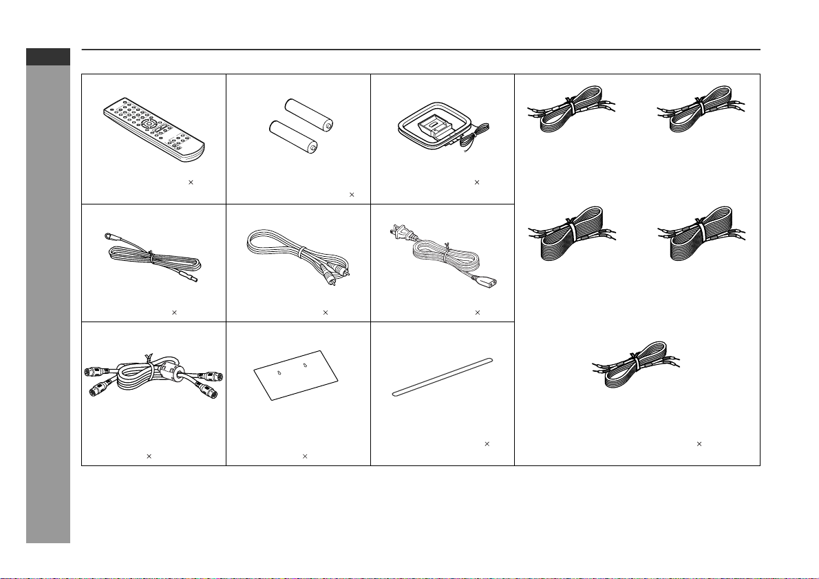
Accessories
Please confirm that the following accessories are included.
E-3
Remote control 1 "AAA" size battery (UM-4,
R03, HP-16 or similar) 2
FM aerial 1 Video cable 1 AC power lead 1
General Information
System connection cable 1Pattern paper for main
unit 1
Caution:
Do not use the supplied AC power lead for other equipment. Fire or
electric shock may result.
Note:
Only the above accessories are included.
White
(for left front
speaker)
AM loop aerial 1
Button name label 1 Speaker connection lead 5
approx. 5 m (16 feet)
Blue
(for left surround
speaker)
approx. 15 m (49 feet)
(for centre speaker)
approx. 5 m (16 feet)
approx. 15 m (49 feet)
Green
Red
(for right front
speaker)
approx. 5 m (16 feet)
Grey
(for right surround
speaker)
Page 5

Contents
Page
General Information
Precautions . . . . . . . . . . . . . . . . . . . . . . . . . . . . . . . . . . . . . . . . . 5
Description of discs . . . . . . . . . . . . . . . . . . . . . . . . . . . . . . . . .6 - 8
Controls and indica t ors . . . . . . . . . . . . . . . . . . . . . . . . . . . . .9 - 13
Page
Audio CD Operation
Playing an a udio CD
To play in random order (random play) . . . . . . . . . . . . . . . . . . 39
To start playback from the desired point (direct play) . . . . . . 40
HT-X1
ENGLISH
Preparation for Use
System installa tion . . . . . . . . . . . . . . . . . . . . . . . . . . . . . . . . . . 14
Main unit prepar a t ion . . . . . . . . . . . . . . . . . . . . . . . . . . . . . . . . 15
System connection s . . . . . . . . . . . . . . . . . . . . . . . . . . . . . .16 - 22
Remote control . . . . . . . . . . . . . . . . . . . . . . . . . . . . . . . . . . . . . . 23
General contro l . . . . . . . . . . . . . . . . . . . . . . . . . . . . . . . . . . . . . 24
DVD Operation
Playing a disc . . . . . . . . . . . . . . . . . . . . . . . . . . . . . . . . . . . .25 - 27
Basic operation
To locate the beginnin g of a chapter/track (skip) . . . . . . . . . . 2 8
Fast forward/Fast reverse (search) . . . . . . . . . . . . . . . . . . . . . 28
To start playback from the desired point (direct play) . . . . . . 29
Useful operation
To change the subtitle language . . . . . . . . . . . . . . . . . . . . . . . 30
To change the audio language (audio outp ut) . . . . . . . . . . . . 31
To brighten an ima ge . . . . . . . . . . . . . . . . . . . . . . . . . . . . . . . . . 31
To improve the image quality . . . . . . . . . . . . . . . . . . . . . . . . . . 32
To select a title from the top menu of the disc . . . . . . . . . . . . 3 3
To select a subtitle or audio language from the disc menu . . . 33
Still picture/F r a me a dva nce . . . . . . . . . . . . . . . . . . . . . . . . . . . 33
Slow-motion pla y . . . . . . . . . . . . . . . . . . . . . . . . . . . . . . . . . . . . 33
To change the angl e . . . . . . . . . . . . . . . . . . . . . . . . . . . . . . . . . 34
To zoom in on an image (zoom) . . . . . . . . . . . . . . . . . . . . . . . . 34
To play in the desired order (programmed playback) . . . . . . 35
To play repeate dly (repeat play) . . . . . . . . . . . . . . . . . . . . . . . . 3 6
To play the contents between the specified points repeatedly
(A-B repeat) . . . . . . . . . . . . . . . . . . . . . . . . . . . . . . . . . . . . . . . . 37
To change the displa y on the main unit . . . . . . . . . . . . . . . . . 37
To change the display on TV screen . . . . . . . . . . . . . . . . . . . . 38
Super Video CD/Video CD Operation
Playing a super video CD or video CD
Playing a super video CD or video CD with P. B. C. (playback
control) . . . . . . . . . . . . . . . . . . . . . . . . . . . . . . . . . . . . . . . . . . . . 41
MP3, WMA and JPEG Disc Operation
Playing an MP3, WMA or JPEG disc . . . . . . . . . . . . . . . . . 42, 43
Radio
Listening to the r ad io . . . . . . . . . . . . . . . . . . . . . . . . . . . . .44 - 46
Advanced Features
Enjoying surround sound (sound mode) . . . . . . . . . . . . .47 - 50
Changing the de f ault setting of the ampli f ie r . . . . . . . . . .51 - 53
Changing the initial setting of D VD . . . . . . . . . . . . . . . . . .54 - 57
Language code list for dis c la nguage . . . . . . . . . . . . . . . . . . . 58
Sleep operati on . . . . . . . . . . . . . . . . . . . . . . . . . . . . . . . . . . . . . 59
Audio connecti on t o other equipment . . . . . . . . . . . . . . . . . . . 60
To install the main unit on the wall . . . . . . . . . . . . . . . . . . . . . 61
References
Troubleshooti ng c ha r t . . . . . . . . . . . . . . . . . . . . . . . . . . . . . 62, 63
Maintenance . . . . . . . . . . . . . . . . . . . . . . . . . . . . . . . . . . . . . . . . 64
Error indicators and warnings . . . . . . . . . . . . . . . . . . . . . . . . . 64
Optional accessory . . . . . . . . . . . . . . . . . . . . . . . . . . . . . . . . . . 64
Specificati ons . . . . . . . . . . . . . . . . . . . . . . . . . . . . . . . . . . . 65, 66
General Information
E-4
Page 6
HT-X1
ENGLISH
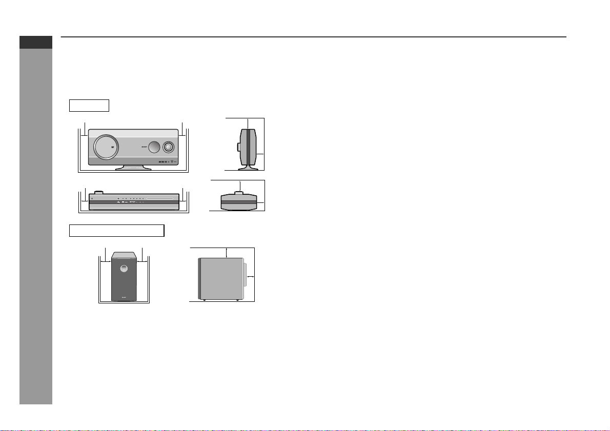
Precautions
General
Please ensure that the equipment is positioned i n a well venti-
z
lated area and that there is at least 10 cm (4") of free space along
the sides and back. There must also be a m inim um o f 15 c m (6")
of free space on the top of the unit.
Main unit
10 cm (4") 10 cm (4")
10 cm (4") 10 cm (4")
Subwoofer/amplifier unit
10 cm (4") 10 cm (4")
General Information
Use the system on a firm, level surface free from vibration.
z
Keep the system away from direct sunlight, strong magnetic
z
fields, excessive dust, humidity and electronic/electrical equipment (home computers, facsimiles, etc.) which generate electr ical noise.
Do not place anything on top of the components.
z
Do not expose the system to moisture, to temperatures higher
z
than 60°C (140°F) or to extremely low temperatures.
15 cm (6")
15 cm (6")
15 cm (6")
10 cm (4")
10 cm (4")
10 cm (4")
If your system does not work proper ly, disconnec t the AC power
z
lead from the wall socket. Plug the AC power lead back in, and
then turn on your system.
In case of an electrical storm, unplug the subwoofer/amplifier unit
z
for safety.
Hold the AC power plug by the head when removing it from the
z
wall socket, as pulling the lead can damage internal wires.
z
Do not remove the outer cover, as this may result in electric
shock. Refer internal service to your local SHARP service
facility.
The ventilation should not be impeded by covering the ventilation
z
openings with items, such as newspapers, tablecloths, curtains,
etc.
No naked flame sources, such as lighted candles, should be
z
placed on the components of the system.
Attention should be drawn to the environmental aspects of bat-
z
tery disposal.
This system should only be used wi thin the range o f 5°C - 35°C
z
(41°F - 95°F).
Warning:
The voltage used must be the same as that specified by this system. Using this product with a higher voltag e other than that speci fied is dangerous and may result in a fire or other types of accident,
causing damage. SHARP will not be held responsible for any damage resulting from the use of this system wit h a voltage other than
that specified.
Volume control
The sound level at a given volume setting d epends on speaker effi ciency, location, and various ot her factors. It is advisable to avoi d
exposure to high volume levels. D o not turn the vol ume on to full at
switch on and listen to music at moderate levels.
E-5
Page 7
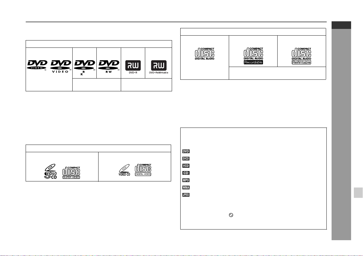
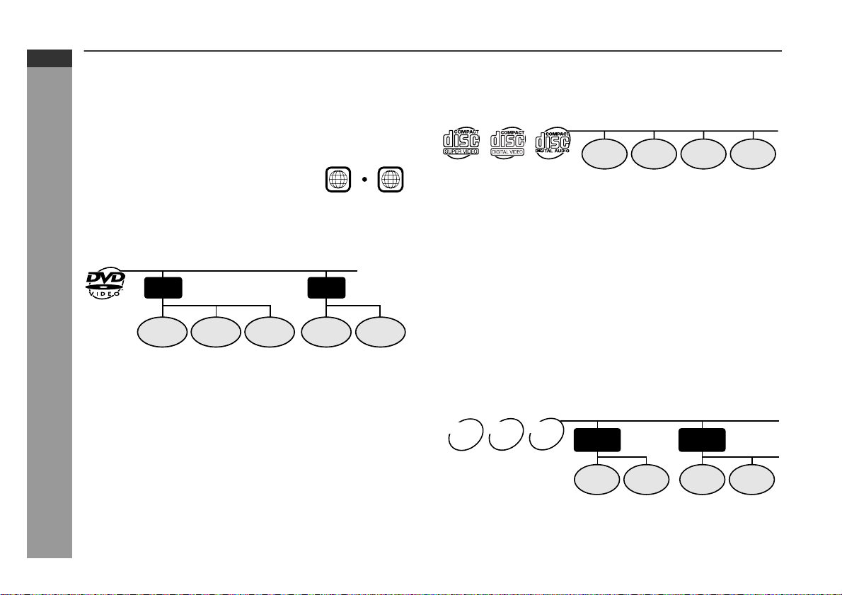
Description of discs
Types of playable discs
The unit can play back discs bearing any of the following marks:
DVD
DVD-Video Disc DVD-R DVD-RW DVD+R DVD+RW
HT-X1
ENGLISH
CD
Audio CD Audio CD-R Audio CD-RW
4.7
Recorded in the video mode (*1) (*2)
(*1) Some discs may not play properly due to the status of the
equipment used for recording, characteristics of the discs,
scratches, dirt, or dirty optical pickup lens.
(*2) DVD-RW discs recorded in VR mode (Video Recording format)
cannot be played back.
Some DVD may not function as described in the manual. See
the disc jacket for restrictions.
Video CD
Super video CD Video CD
Recorded in the video
mode (*1)
Or CDV (*1) CD-R/RW recorded in MP3/WMA/JPEG
(*1) Only the audio on the CDV can be played.
(*2) Some discs may not play properly due to the status of the
equipment used for recording, characteristics of the discs,
scratches, dirt, or dirty optical pickup lens.
For unplayable discs, see page 8.
z
Icons used in this operation manual
Some functions may not be available depending on discs. The following icons indicate the discs that can be used in the section.
... Indicates DVDs.
... Indicates super video CDs.
... Indicates video CDs.
... Indicates audio CDs.
... Indicates CD-R/RW with MP3 recording.
... Indicates CD-R/RW with WMA recording.
... Indicates CD-R/RW with JPEG recording.
Some operations may not be performed depending on discs
z
even if they are described in this manual.
During operation, " " may be displayed on the screen. This
z
means that the operations described in this manual are prohibited by the disc.
format (*2)
General Information
E-6
Page 8
HT-X1
ENGLISH
Description of discs (continued)
DVD-Video
A popular type of DVD disc of the same size as a CD, mainly containing video images.
Region num ber
DVD discs are programmed with region
numbers indicating countries in which
they can be played. This system can
play discs with region number "4" or
"ALL".
Title and chapter
DVD-Video discs are divided into "ti tles" and "chapters". If the di sc
has more than one movie on it, each movie is a separate "title".
"Chapters" are subdivisions of titles.
Region number
(playable area number)
4
ALL
Super video CD/video CD/audio CD
Track
Super video CD, video CD and audio CD are composed of "tracks".
Tracks are equivalent to songs on a CD.
Track 1 Track 2 Track 3 Track 4
MP3/WMA/JPEG format on CD-R/CD-RW
An MP3 file is an audio data compressed in the MPEG 1 audio layer
3 format. MP3 files have the extension ".mp3". (Files with the extension ".mp3" may not play, or noise may occur during playback i f not
recorded in the MP3 format.)
E-7
Title 1 Title 2
Chapter 1
General Information
DVD-R/DVD-RW/DVD+R/DVD+RW
You can play DVD-R/DVD-RW/DVD+R/DVD+RW discs recorded
z
in the video mode.
z
Before playing DVD-R/DVD-RW/DVD+R/DVD+RW discs with
this unit, finalize them with the equipment used for recording.
Chapter 2 Chapter 3 Chapter 1 Chapter 2
WMA is an audio file format developed by Microsoft with the ".wma"
extension. This type of audio file is recorded through Microsoft Windows operating system.
A JPEG file is still image data compressed in the JPEG (Joint Photographic Experts Group) format. JPEG files have the extension
".jpg".
Folder and file
MP3/WMA/JPEG discs consist of "folders" and "files".
JPEG
WMA
MP3
disc
disc
disc
Folder 1
File 1
Folder 2
File 2 File 1
File 2
Page 9
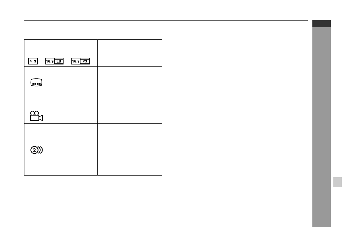
Icons used on DVD discs
Check the icons of the DVD jacket before playing your discs.
Display Description
Format recorded on the DVD
Type of subtitles recorded
Example: You can select a subtitle lan-
2
1. English
2. German
Number of camera angles
2
Number of audio tracks and audio recording systems
Example:
1: Original <English>
(Dolby Digital 5.1 Surround)
2. German (Dolby Digital 2 ch)
Select a type according to the
connected TV type.
Recorded subtitle languages.
guage.
Number of angles recorded on
the DVD.
You can view scenes from different angles.
The number of audio tracks
and audio recording systems
are indicated.
You can change the audio
z
language.
Audio and recording sys-
z
tem vary depending on the
DVD. Check them in the
DVD's manual.
Discs that cannot be played
DVDs without the region num-
z
ber "4" or "ALL".
DVDs with SECAM system
z
DVDs with MPEG sound
z
DVD-ROM
z
DVD-RAM
z
Notes:
The discs above cannot be played at all, or no sound is heard
z
although images appear on the screen or vice versa.
Faulty playback may damage the speakers and can have an
z
adverse effect on your hearing when played at high volume settings.
You cannot play illegally produced discs.
z
A disc with scratches or fingerprints may not play properly. Refer
z
to "Care of discs" (page 64) and clean the disc.
DVD-Audio
z
CDG
z
Photo CD
z
CD-ROM
z
SACD
z
Discs recorded in special for-
z
mats, etc.
HT-X1
ENGLISH
General Information
E-8
Page 10

HT-X1
ENGLISH
Controls and indicators
1 2 3 4 5 6 7 8
9
10
General Information
21 34 5 76 8 9
Display
11
12
13
11
Top and front panel
Reference page
1.Disc Eject Button . . . . . . . . . . . . . . . . . . . . . . . . . . . . . . . . . 26
2.Stop Button . . . . . . . . . . . . . . . . . . . . . . . . . . . . . . . . . . . 25, 26
3.Play Button . . . . . . . . . . . . . . . . . . . . . . . . . . . . . . . . . . . . . . 26
4.Chapter (Track) Skip Down or Fast Reverse Button . . . . . 28
5.Chapter (Track) Skip Up or Fast Forward Button . . . . . . . 28
6.Function Selector Button . . . . . . . . . . . . . . . . . . . . . . . . . . 48
7.Tuner (Band) Button . . . . . . . . . . . . . . . . . . . . . . . . . . . . . . 44
8.On/Stand-by Button . . . . . . . . . . . . . . . . . . . . . . . . . . . . . . . 22
9.Disc Compartment . . . . . . . . . . . . . . . . . . . . . . . . . . . . . . . . 25
10.Main Unit Stand . . . . . . . . . . . . . . . . . . . . . . . . . . . . . . . . . . 15
11.Remote Sensor . . . . . . . . . . . . . . . . . . . . . . . . . . . . . . . . . . . 23
12.Volume Control . . . . . . . . . . . . . . . . . . . . . . . . . . . . . . . . . . . 24
13.Headphone Socket . . . . . . . . . . . . . . . . . . . . . . . . . . . . . . . . 21
Rear panel
Reference page
1.FM 75 Ohm Aerial Socket . . . . . . . . . . . . . . . . . . . . . . . 16, 17
2.Aerial Earth Terminal . . . . . . . . . . . . . . . . . . . . . . . . . . . 16, 17
3.AM Aerial Terminal . . . . . . . . . . . . . . . . . . . . . . . . . . . . . 1 6 , 1 7
4.Auxiliary (Audio Signal) Input Sockets . . . . . . . . . . . . . . . . 60
5.Component Video Output Sockets . . . . . . . . . . . . . . . . . . . 20
6.S- video Output Socket . . . . . . . . . . . . . . . . . . . . . . . . . . . . . 20
7.Video Output Socket . . . . . . . . . . . . . . . . . . . . . . . . . . . . . . 19
8.Sys tem Connection Sockets
(to subwoofer/amplifier unit) . . . . . . . . . . . . . . . . . . . . . 16, 17
9.Optical Digital Audio Input Socket . . . . . . . . . . . . . . . . . . . 60
Removing the back cover of
the main unit:
For system connections, remove
the back cover first.
1
E-9
2
Page 11
HT-X1
ENGLISH
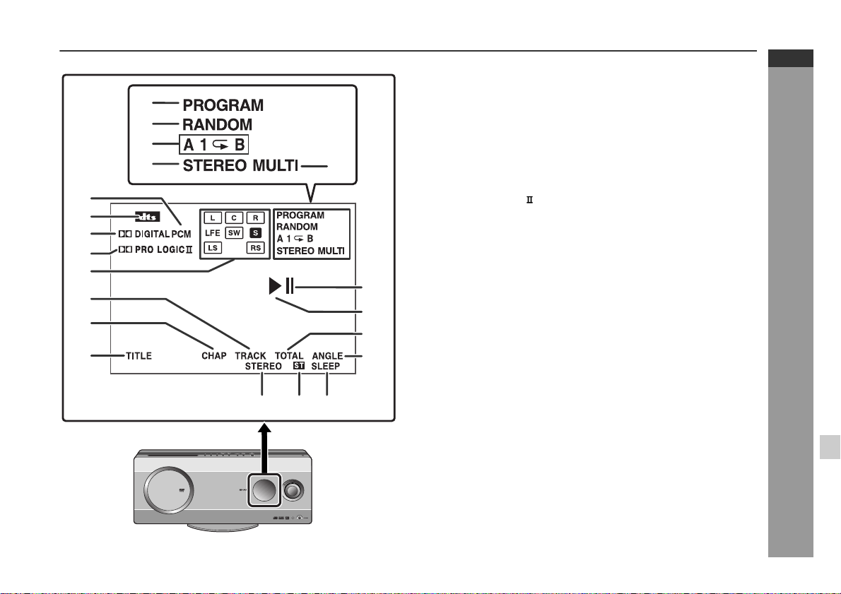
Display
Reference page
10
11
12
13
1
2
3
4
5
6
7
8
9
14
15
16
1.Programme Indicator . . . . . . . . . . . . . . . . . . . . . . . . . . . 35, 45
2.Random Play Indicator . . . . . . . . . . . . . . . . . . . . . . . . . . . . 39
3.Repeat/One Track Repeat/A - B Repeat Indicators . . . 36, 37
4.2 channel Stereo Sound Mode Indicator . . . . . . . . . . . . . . 49
5.Multi Channel Sound Mode Indicato r . . . . . . . . . . . . . . . . . 50
6.PCM Signal Indicator . . . . . . . . . . . . . . . . . . . . . . . . . . . . . . 47
7.DTS Signal Indicator . . . . . . . . . . . . . . . . . . . . . . . . . . . . . . 47
8.Dolby Digital Signal Indicator . . . . . . . . . . . . . . . . . . . . . . . 47
9.Dolby Pro Logic Indicator . . . . . . . . . . . . . . . . . . . . . . . . 47
10.Audio Signal/Speaker Indicators . . . . . . . . . . . . . . . . . . . . 48
11.Track Indicator . . . . . . . . . . . . . . . . . . . . . . . . . . . . . . . . . . . 37
12.Chapter Indicator . . . . . . . . . . . . . . . . . . . . . . . . . . . . . . . . . 37
13.Title Indicator . . . . . . . . . . . . . . . . . . . . . . . . . . . . . . . . . . . . 37
14.Pause Indicator . . . . . . . . . . . . . . . . . . . . . . . . . . . . . . . . . . 26
15.Play Indicator . . . . . . . . . . . . . . . . . . . . . . . . . . . . . . . . . . . . 26
16.Total Indicator . . . . . . . . . . . . . . . . . . . . . . . . . . . . . . . . . . . 37
17.Angle Indicator . . . . . . . . . . . . . . . . . . . . . . . . . . . . . . . . . . . 34
18.FM Stereo Mode Indicator . . . . . . . . . . . . . . . . . . . . . . . . . . 44
19.FM Stereo Receiving Indicator . . . . . . . . . . . . . . . . . . . . . . 44
20.Sleep Indicator . . . . . . . . . . . . . . . . . . . . . . . . . . . . . . . . . . . 59
17
General Information
18 19 20
E-10
Page 12
HT-X1
ENGLISH
Controls and indicators (continued)
1
2
3
4
5
6
7
8
9
10
11
12
17
18
19
20
13
14
15
16
General Information
28 29
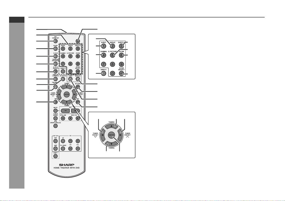
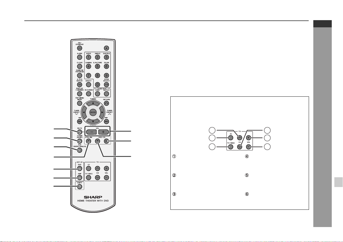
Remote control
1.Remote Control Transmitter . . . . . . . . . . . . . . . . . . . . . . . . 23
2.Direct Number Buttons . . . . . . . . . . . . . . . . . . . . . . . . . . . . 29
21
22
23
24
27
2625
3.On/Stand-by Button . . . . . . . . . . . . . . . . . . . . . . . . . . . . . . . 23
4.Sleep Button . . . . . . . . . . . . . . . . . . . . . . . . . . . . . . . . . . . . . 59
5.Clear Button . . . . . . . . . . . . . . . . . . . . . . . . . . . . . . . . . . . . . 35
6.Random or Programme Button . . . . . . . . . . . . . . . . . . . 35, 39
7.A - B Repeat or Repeat Button . . . . . . . . . . . . . . . . . . . 36, 37
8.Unit Display Select or Dimmer B u t t on . . . . . . . . . . . . . 24, 37
9.On Screen Display On/Off B ut t on . . . . . . . . . . . . . . . . . . . . 38
10.Top Menu or Menu Button . . . . . . . . . . . . . . . . . . . . . . . . . . 33
11.Chapter (Track) Skip Down or Fast Reverse Button . . . . . 28
12.Disc Eject Button . . . . . . . . . . . . . . . . . . . . . . . . . . . . . . . . . 26
13.Multi Channel Select Button . . . . . . . . . . . . . . . . . . . . . . . . 50
14.Return Button . . . . . . . . . . . . . . . . . . . . . . . . . . . . . . . . . 51, 54
15.Stereo (2 channel) Select Button . . . . . . . . . . . . . . . . . . . . 49
16.Chapter (Track) Skip Up or Fast Forward Button . . . . . . . 28
17.Angle Button . . . . . . . . . . . . . . . . . . . . . . . . . . . . . . . . . . . . . 34
18.DVD Audio Language Select or
CD Audio Output Select Button . . . . . . . . . . . . . . . . . . . . . 31
19.Gamma Button . . . . . . . . . . . . . . . . . . . . . . . . . . . . . . . . . . . 31
20.Direct Button . . . . . . . . . . . . . . . . . . . . . . . . . . . . . . . . . . . . . 29
21.Subtitle Button . . . . . . . . . . . . . . . . . . . . . . . . . . . . . . . . . . . 30
22.Super Picture Button . . . . . . . . . . . . . . . . . . . . . . . . . . . . . . 32
23.Zoom Button . . . . . . . . . . . . . . . . . . . . . . . . . . . . . . . . . . . . . 34
24.Progressive Scan Mode Select Button . . . . . . . . . . . . . . . . 19
25.Tuner Preset Down or Cursor Button . . . . . . . . . . . . . . 34, 45
26.Tuning Up or Cursor Button . . . . . . . . . . . . . . . . . . . . . 34, 44
27.Tuner Preset Up or Cursor Button . . . . . . . . . . . . . . . . 34, 45
28.Tuning Down or Cursor Button . . . . . . . . . . . . . . . . . . . 34, 44
29.Enter Button . . . . . . . . . . . . . . . . . . . . . . . . . . . . . . . . . . . . . 29
Reference page
E-11
Page 13
HT-X1
ENGLISH
Remote control
1.Mute Button . . . . . . . . . . . . . . . . . . . . . . . . . . . . . . . . . . . . . 24
2.Tuner (Band) Button . . . . . . . . . . . . . . . . . . . . . . . . . . . . . . 44
3.Auxiliary Button . . . . . . . . . . . . . . . . . . . . . . . . . . . . . . . . . . 60
4.Frame Advance or Pause Button . . . . . . . . . . . . . . . . . 26, 33
5.DVD Initial Setting Button . . . . . . . . . . . . . . . . . . . . . . . . . . 54
6.Amplifier Initial Setting Button . . . . . . . . . . . . . . . . . . . . . . 5 2
7.Shift Button . . . . . . . . . . . . . . . . . . . . . . . . . . . . . . . . . . . . . 30
8.Volume Up and Down Buttons . . . . . . . . . . . . . . . . . . . . . . 24
9.Play Button . . . . . . . . . . . . . . . . . . . . . . . . . . . . . . . . . . . . . . 26
10.Stop Button . . . . . . . . . . . . . . . . . . . . . . . . . . . . . . . . . . 25, 26
TV Operation Buttons
You can operate some functions of SHARP' TVs with the remote
control of this system.
However, some models cannot be operated.
Reference page
1
2
8
9
3
4
10
TV Channel Up Button TV Channel Down Button
Switches the TV channel up. Switches the TV channel
5
6
7
TV On/Stand-by Button TV Volume Up Button
Sets the TV power to "ON"
or "STAND-BY".
TV/VCR Input Select Button
Switches the input to TV or
VCR.
1
2
3
4
5
6
General Information
down.
Turns up the TV volume.
TV Volume Down Bu tton
Turns down the TV volume.
E-12
Page 14
HT-X1
ENGLISH
Controls and indicators (continued)
1
2
1
2
General Information
1
3
2
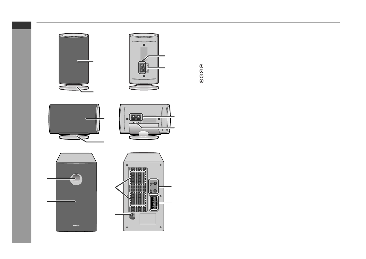
Front/surround speakers
1.Speaker
2.Speaker Stand . . . . . . . . . . . . . . . . . . . . . . . . . . . . . . . . . . . 18
3
4
3.Speaker Terminals . . . . . . . . . . . . . . . . . . . . . . . . . . . . . 16, 18
4.Colour Label
White ... Left Front Speaker
Red ... Right Front Speaker
Blue ... Left Surround Speaker
Grey ... Right Surround Speaker
Reference page
Centre speaker
3
1.Speaker
2.Speaker Stand
4
3.Speaker Terminals . . . . . . . . . . . . . . . . . . . . . . . . . . . . . 16, 18
4.Colour Label: Green
Reference page
Subwoofer/amplifier unit
1.Bass Reflex Duct
2.Woofer
3.Cooling Fan . . . . . . . . . . . . . . . . . . . . . . . . . . . . . . . . . . . . . . 22
5
4.AC Power Input Socket . . . . . . . . . . . . . . . . . . . . . . . . . . . . 22
5.Sys tem Connection Sockets (to main unit) . . . . . . . . . 16, 17
6.Speaker Terminals . . . . . . . . . . . . . . . . . . . . . . . . . . . . . 16, 18
Reference page
6
E-13
4
Page 15
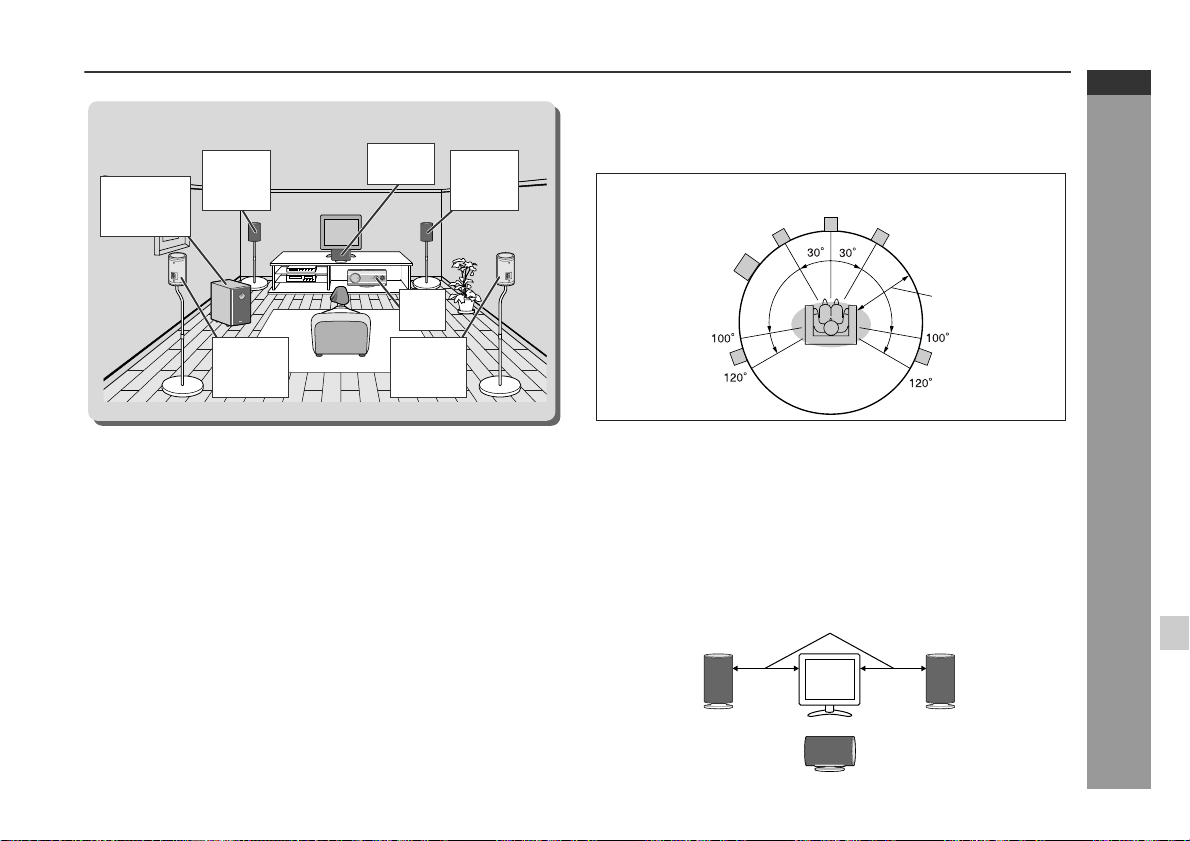
System installation
Installation image (with optional accessories):
Front
Subwoofer/
amplifier
unit
speaker
(left)
Surround
speaker
(left)
Magnetically shielded speakers
The front and centre speakers may be placed beside or near the TV
as they are magnetically shielded. However, colour variation may
occur, depending on the type of the TV.
If colour variation occurs...
Turn off the TV (from the power switch).
After 15 - 30 minutes, turn the TV on again.
If the colour variation is still present...
Move the speakers further away from the TV.
Refer to the user's manual of the TV for details.
Centre
speaker
Main
unit
Surround
speaker
(right)
Front
speaker
(right)
Placing the speaker system
The best surround effect will be achieved by placing each
speaker at the same distance from the listening position.
It is recommended to arrange the speakers as shown below.
Centre
Front speaker (left)
Subwoofer/
amplifier unit
Surround
speaker (left)
Notes:
The default distance is set to 2 m (6 feet). If speakers cannot be placed
z
at equal distances, refer to "Speaker delay setting" (see page 52).
Place the TV halfway between the front speakers.
z
It is recommended that the centre speaker be placed near the
z
television.
Place the surround speakers at a position just above the height of
z
your ears.
You can place the subwoofer/amplifier unit anywhere you like. As
z
it vibrates whilst reproducing bass, place it on a stable, sturdy
surface.
speaker
Same distance
Front speaker (right)
Default setting:
2 m (6 feet)
Surround
speaker (right)
HT-X1
ENGLISH
Preparation for Use
Note:
The surround speakers and subwoofer/amplifier unit are not magnetically shielded.
Front speaker
(left)
Front speaker
(right)
Centre speaker
E-14
Page 16
HT-X1
ENGLISH
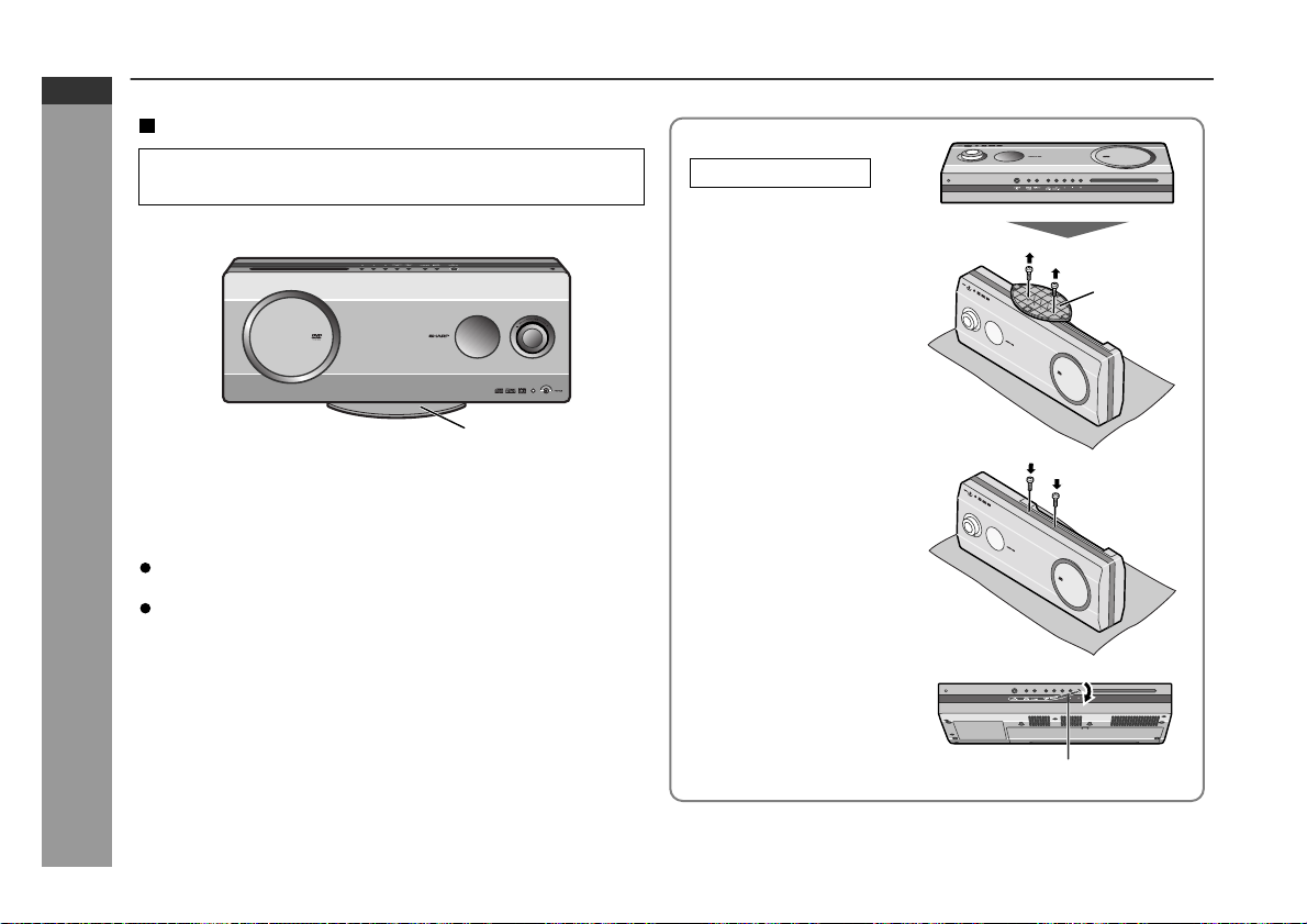
Main unit preparat ion
Installation methods
Make sure to unplug the AC power lead before installing
the main unit or change the position.
The stand is attached to the main unit at the factory.
Stand
You can also place the main unit horizontally or mount it on the
wall without the stand.
(See page 61 for mounting it on the wall.)
Notes:
When attaching or removing the stand, place the main unit on
Preparation for Use
a cushion or soft cloth to avoid damage.
Remove the only specified screws. Malfunction may occur. Be
careful not to lose the removed screws.
Caution:
Do not change the installation direction when the main unit is
turned on. Disc may not be read or may be damaged.
Placing horizontally
1 Remove the 2 screws
and the stand.
2 Fix the removed screws.
3 Attach the included
button name label.
Stand
Button name label
E-15
Note:
Attach the button name label carefully. It is difficult to peel off.
Page 17
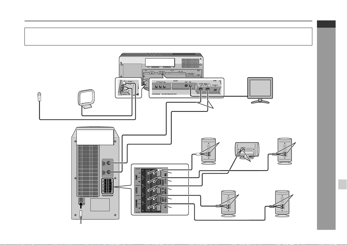
System connections
z
Make sure to disconnect the AC power lead from the wall socket before you connect/disconnect cables to/from sockets inside
the back cover of the main unit or sockets of the subwoofer/amplifier unit.
z
After connecting cables, attach the back cover and operate the main unit.
HT-X1
ENGLISH
Aerial connection
(see page 17)
AM loop aerial
FM aerial
Connecting
the AC
power lead
(see page 22)
Subwoofer/
amplifier unit
Main unit
White
Red
Green
Blue
Grey
TV connection
(see pages 19, 20)
Connecting the system
connection cable
Front speaker
(left)
White
Surround speaker
(left)
Centre
speaker
Green
(see page 17)
Front speaker
Surround speaker
(right)
Speaker connection (see page 18)
(right)
Red
Preparation for Use
GreyBlue
E-16
Page 18
HT-X1
ENGLISH
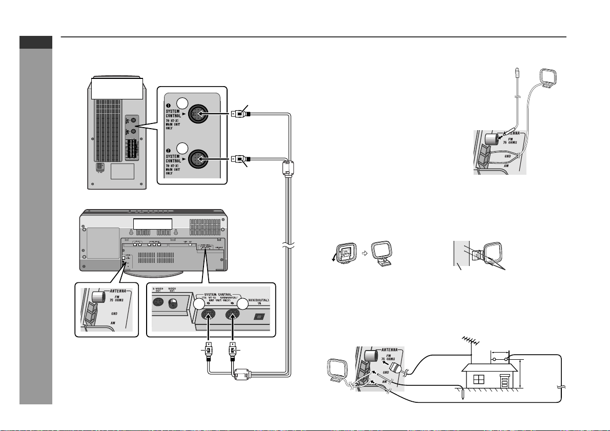
System connections (continued)
Connecting the system connection cable
Connect the main unit and subwoofer/amplifier unit as follows.
Subwoofer/
amplifier unit
1
2
Main unit
Black
Blue
Aerial connection
Supplied FM aerial:
Connect the FM aerial wire to the FM 75
OHMS socket and position the FM aerial
wire in the direction where the strongest
signal can be received.
Supplied AM loop aerial:
Connect the AM loop aerial wire to the
AM and GND terminals. Position the AM
loop aerial for optimum reception. Place
the AM loop aerial on a shelf, etc., or attach it to a stand or a wall with screws
(not supplied).
Note:
Placing the aerial on the system or near the AC power lead may cause
noise pickup. Place the aerial away from the system for better reception.
Installing the AM loop aerial:
< Assembling > < Attaching to the wall >
FM
aerial
AM loop
aerial
E-17
Preparation for Use
Aerial terminals
2
Blue Black
1
Wall Screws (not supplied)
External FM or AM aerial:
Use an external FM or AM aerial if you require better reception.
Consult your dealer.
When using an external AM aerial, be sur e to keep the wire of the
AM loop aerial connected.
AM loop
aerial
External
FM aerial
Earth wire
External AM aerial
15 m (49 feet)
7.5 m
(25 feet)
Earth rod
Page 19
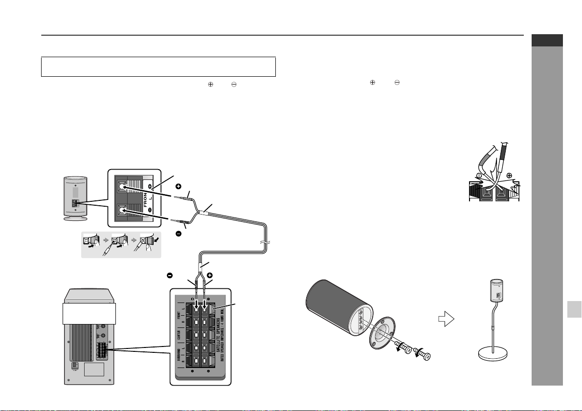
Speaker connection
Make sure to leave the AC power lead disconnected when connecting the speakers.
To prevent accidental short circuits between and terminals,
connect the speaker wires to the speakers first and then to the
subwoofer/amplifier unit.
When connecting speakers, match the colours of the back
label, tube for the speaker wire, and speaker terminal of the
subwoofer/amplifier unit.
1 Connect the wires to the speakers.
Example: To connect the left front speaker.
Label (white)
Red
Tube (white)
Black
2 Connect the other end to the
subwoofer/amplifier unit.
Subwoofer/
amplifier unit
Black
Tube (white)
Red
Speaker
terminal
(white)
Caution:
z
The supplied speakers are exclusively for the HT-X1. Do not
connect them to other equipment, and do not connect other
speakers to the HT-X1. It may cause malfunction.
Do not mistake the and , and right and lef t terminals of the
z
speaker wires. (The right speaker is placed on the right when you
face the subwoofer/amplifier unit.)
Do not stand or sit on the speakers. You may be injured.
z
Do not allow any objects to fall into or to be placed in the bass
z
reflex ducts.
The speaker grilles are not removable.
z
z
Do not short-circuit the speaker wire. If it
happens with the power on, the protection
circuit is activated and the system enters the
stand-by mode. In this case, check that the
speaker wire is connected correctly before
turning on the power again.
Incorrect
Attaching the optional floor speaker stand
The front speakers and surround speakers support the optional floor
speaker stand (see page 64). Remove the orig inal stand for each
speaker using a screwdriver first. For details, refer to the manual for
the floor speaker stand.
HT-X1
ENGLISH
Preparation for Use
Note:
Keep the removed speaker stands or screw in a safe place.
E-18
Page 20
HT-X1
ENGLISH
System connections (continued)
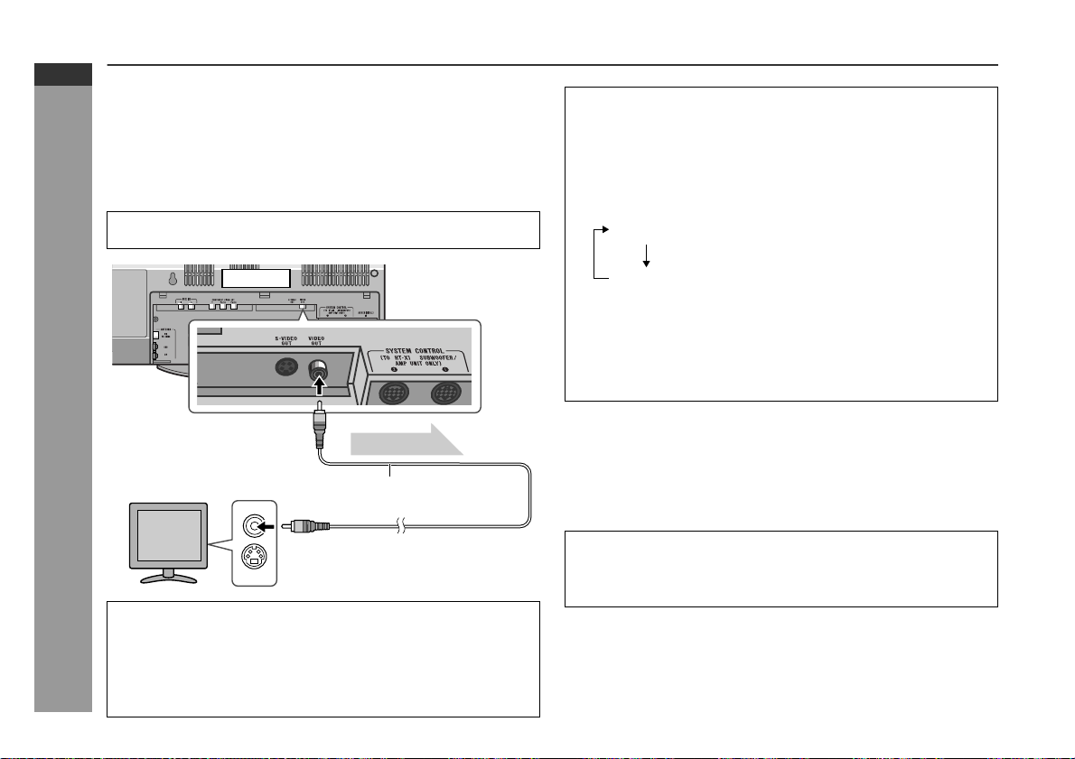
TV connection
Three types of sockets (VIDEO OUT, S-VIDEO OUT and COMPONENT VIDEO OUT) are available for connection of a TV and the
main unit. Connect according to your TV.
Connecting to a TV with a video input socket:
You can enjoy DVD images by connecting your TV and the main
unit with the supplied video cable.
Set the video mode to "Interlace" (default setting). For the procedure, refer to "Changing the video output mode".
Main unit
To video
Preparation for Use
output socket
TV
Video signal
Video cable
(supplied)
Changing the video output mode:
1 Insert a DVD disc (steps 1 - 3, page 25).
2 In the stop mode, press the SHIFT button and SCAN SELECT
button on the remote control.
Each time these buttons are pressed, the mode will change in
the following order:
Interlace Select this for a non-progressive scan TV
Progressive
(No display)
Caution:
To enjoy images on a TV, make sure to select the right items
for the following four: video cable, TV's video input socket,
and this unit's video output socket and video output mode.
Otherwise, images do not appear properly.
What is progressive scanning?
The conventional TV system displays 30 frames of still images per
second to complete sequential movement (interlaced scanning).
Whereas, progressive scanning displays one frame every 1/60th of
a second (60 frames per second) to realise less-flicker, high-density
images.
(use a video cable, S-video cable, or
component video cable).
Select this for a progressive scan TV
(use a component video cable).
E-19
To video
input socket
Notes:
Change the TV input in accordance with the connected socket.
z
Do not connect other equipment (VCR, etc.) between the TV and
z
the main unit. Images may be distorted.
Refer to the operation manual of the equipment to be connected.
z
Insert the plugs fully to avoid fuzzy pictures or noise.
z
Compatibility of the progressive scan TV
Some progressive scan TVs are not fully compatible with this product, which may cause image distortion. In this case, switch the video mode from "Progressive" to "Interlace".
Page 21
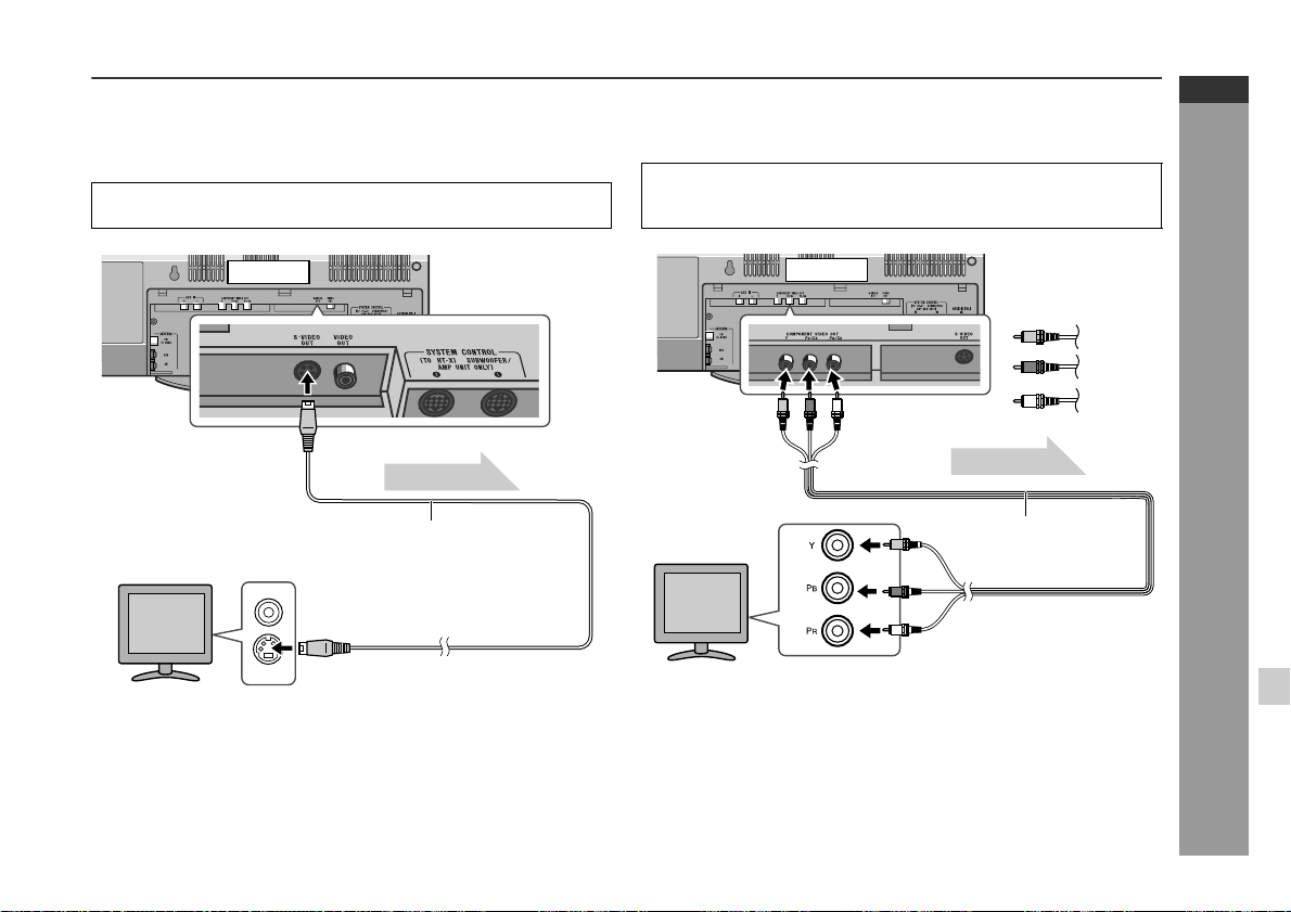
Connecting to a TV with an S-video input socket:
If your TV is equipped with an S-video input socket, you can enjoy
higher quality images by connecti ng it with an S-video cable (not
supplied).
Set the video mode to "Interlace" (default setting). For the procedure, refer to "Changing the video output mode" on page 19.
HT-X1
ENGLISH
Connecting to a TV with component video input sockets:
If your TV is equipped with component video input sockets, purchase a component video cable to enjoy higher quality images.
For a progressive scan TV, set the video mode to "Progressive".
Select "Interlace" for a non-progressive scan TV. For the procedure, refer to "Changing the video output mode" on page 19.
Main unit
To S-video
output socket
TV
To S-video
input socket
Note:
When the video and S-video cables are both connected, the images
from the S-video input socket appears on your TV.
Video signal
S-video cable
(commercially available)
Main unit
Green
Blue
To component
video output
sockets
TV
Notes:
If your TV has different indications for the component video
z
inputs (Y, CB and CR or Y, B-Y and P-Y), connect sock ets with
its matching colour.
Some component video sockets designed for the high-vision sys-
z
tem are not compatible with DVD. Do not connect this unit to
those component video input sockets. (Images may appear distorted or may not appear due to the system difference.)
Video signal
Component video cable
(commercially available)
To component
video input sockets
Red
Preparation for Use
E-20
Page 22

HT-X1
ENGLISH
System connections (continued)
Attaching the back cover
After making all the connections, attach the back cover to the main
unit. Fit the claws into the holes.
Preparation for Use
Headphones
Before plugging in or unplugging the headphones, reduce the
z
volume.
Be sure your headphones have a 3. 5 mm (1/8") diameter plug
z
and impedance between 16 and 50 ohms. The rec ommended
impedance is 32 ohms.
Plugging in the headphones disconnec ts the speakers automati-
z
cally. Adjust the volume using the VOLUME control.
E-21
Page 23

Connecting the AC power lead
After checking all the connections have been made correctly, plug
the AC power lead to the AC power input socket of the subwoofer/
amplifier unit, and then to the wall socket.
HT-X1
ENGLISH
To turn the power on
Press the ON/STAND-BY button.
If the power does not turn on, check if the AC power lead and sy stem connection cable are plugged in properly.
Subwoofer/
amplifier unit
Cooling fan
Wall socket
(AC 120 V, 60 Hz)
Notes:
Never use a power lead other tha n the one supplied . Otherwise,
z
a malfunction or an accident may occur.
Unplug the AC power lead from the wall soc ket i f the subwoofer/
z
amplifier unit will not be in use for a prolonged period of time.
Cooling fan:
A cooling fan is built into this subwoofer/amplifier unit for better heat
radiation. Do not cover the opening in this section with any obstacles to avoid damage to the subwoofer/amplifier unit.
To set the system to stand- by mode:
Press the ON/STAND-BY button again.
Note:
After the system enters the powe r stand- by mode, wait a few seconds to turn on again.
Subwoofer/
amplifier unit
Main unit
Preparation for Use
E-22
Page 24

HT-X1
ENGLISH
Remote control
Battery installation
1 Remove the battery cover.
2 Insert the supplied batteries according to the direction indi-
cated in the battery compartment.
When inserting or removing the batteries, push them toward the
battery terminals.
3 Replace the cover.
Precautions for battery use:
Replace all old batteries with new ones at the same time.
z
Do not mix old and new batteries.
z
Remove the batteries if the system will not be used for long peri-
z
ods of time. This will prevent potential damage due to battery
Preparation for Use
leakage.
Caution:
Do not use rechargeable batteries (nickel-cadmium battery, etc.).
z
Installing the batteries incorrectly may cause the system to mal-
z
function.
Battery removal:
Remove the battery cover. Push each battery toward the battery
terminal and take them out.
Notes concerning use:
Replace the batteries if the operating distance is reduced or if the
z
operation becomes erratic. Purchase 2 "AAA" size batteries (UM4, R03, HP-16 or similar).
Periodically clean the transmitte r on the remote control and the
z
sensor on the main unit with a soft cloth.
Exposing the sensor on the main unit to strong light may interfere
z
with operation. Change the lighting or the direction of the main
unit if this occurs.
Keep the remote control away from moisture, heat, shoc k, and
z
vibrations.
Test of the remote control
Check the remote control after checking all the connections (see
pages 16 - 22).
Point the remote control directly at the r emote sensor on the main
unit.
The remote control can be used within the range shown below:
Press the ON/STAND-BY button. Does the power turn on? Now,
you can enjoy music.
The main unit is equipped with 2 remote sensors. Use them
z
according to the installation method as shown below.
Main unit
Remote sensor
0.2 m - 6 m
(8" - 20')
E-23
Page 25

General control
Volume control
Main unit operation:
When the VOLUME control is turned
clockwise, the volume will increase.
When it is turned anti-clockwise, the
volume will decrease.
Remote control operation:
Press the VOL (+ or -) button to increase or decrease the volume.
0 1 10
......
39 40
Muting
The volume is muted temporarily
when pressing the MUTE button.
Press again to restore the vol-
z
ume.
The mute status is cancelled
z
when you adjust the volume.
To change the display brightness (2 levels)
Hold the DISPLAY/(-DIMMER) button down for 3 seconds or more.
Each time you press, brightness changes.
Dimmed
(*)
Brightened
HT-X1
ENGLISH
Preparation for Use
(*) After approx. 5 seconds of DVD playback , the displ ay di ms and
the original brightness returns when you stop playback. The
brightness remains unchanged during playback of other media.
E-24
Page 26

HT-X1
ENGLISH
Playing a dis c
Turn on the TV, and switch the input to the "VIDEO 1" or "VIDEO 2",
etc. accordingly.
1
Press the ON/STAND-BY button to turn the power on.
2
Press the button to set the input to "DVD".
3
Insert a disc into the disc insertion slot with t he la bel si de
toward you.
The disc enters automatically.
z
Notes:
Do not push in the disc. Damage may result.
z
Load an 8 cm (3") disc gently in the middle of the insertion
z
slot (do not use an adaptor.)
No Disc
DVD
VideoCD
CD
Audio Visual
Entertainment
E-25
Disc insertion slot
Label side
DVD Operation
Label side
Disc insertion slot
Some discs play automatically.
Page 27

4
If playback does not start, press the (DVD/CD ) button.
The sound mode in use appears during DVD playback.
Play indicator
Chapter or track number
When the menu appears on the TV screen:
On DVD, select an item by using the cursor ( , , or ) button
and press the ENTER button.
On super video CD or video CD, select an item by using the direct number buttons.
To interrupt playback:
Press the STILL button on the remote control.
To resume playback from the same point, press
the DVD/CD button.
To stop playback:
DVD:
Press the button twice.
SVCD/VCD/CD/MP3/WMA/JPEG:
Press the button.
Playing time
Caution w he n inserting disc:
Do not touch the playback side.
z
Do not insert two or more discs in the disc insertion slot.
z
Discs with labels, stickers or glue attached
z
may cause damage to the main unit.
Do not use discs of special shapes (heart, oc-
z
tagon, etc.) or 8 cm (3") discs with an adaptor.
Malfunction may result.
A disc with scratches or fingerprints may not play properly. Re-
z
fer to "Care of discs" (page 64) and clean the disc.
Insert or remove the disc straight. Otherwise,
z
damage may result.
To remove the disc:
1. In the stop mode, press the button.
2. Remove the disc.
HT-X1
ENGLISH
Disc
DVD Operation
E-26
Page 28

HT-X1
ENGLISH
Playing a disc (continued)
Notes:
When you turn on the power or switch t he input to "DVD" i nitiali-
z
sation starts and operation is not possible for a few seconds.
Stop positions may be recorded on some discs. When you play
z
such a disc, playback stops there.
During an operation, " " may appear indicating that the opera-
z
tion is disabled by the disc.
Some DVD may not function as described in the manual. See the
z
disc jacket for restrictions.
Some CD-R/CD-RW may not play properly due to the stat us of
z
the disc or equipment used for record ing. Change the recording
speed or disc. For more details, see the manual for the equipment.
Sound may skip at high volume depending on the disc. In this
z
case, turn down the volume.
Caution:
Be careful not to damage the disc when inserting or removing it.
z
A disc does not play if damaged, dirty or loaded upside down.
z
Make sure to remove the disc before transporting the main unit.
z
Otherwise the disc inside may cause malfunction.
Do not let coins, clips, etc. get into the disc inser tion slot. Mal-
z
function may occur.
When attempting to play discs with scr atches or of a different
z
DVD Operation
region number, or unplayable or restricted (*1) discs, an error
message will appear on the TV display and the disc will not play.
(*1)Viewing is prohibited on some DVDs according to the audi-
ence age.
To resume playback after stopping (resume
play)
You can resume playback from the point playback is stopped.
1
Whilst the disc is playing, press
the button.
The system stores the point you stopped.
2
To restart play, press the
(DVD/CD ) button.
Playback resumes from the point you left off.
To cancel resume play:
Press the button again.
Notes:
The resume play feature is disabled on some discs.
z
Depending on the disc, playback may resume slight ly before the
z
position where it was stopped.
Pre-Stop
Play
Stop
E-27
Page 29

Basic operation
Fast forw ard/Fast reverse (search)
You can search the desired point as you play the disc.
1
Whilst a disc is playing, hold
down the or button for 2
seconds or more.
The scanning speed will change as follows at each press of the
button.
The speed changes as follows on DVD/super video CD/video
CD/audio CD:
Fast Forward 2x
HT-X1
ENGLISH
To locate the beginning of a chapter/track
(skip)
You can skip the current chapter (track) to the next or previous.
Whilst a disc is playing, press the
or button.
Press the button to skip to the next
chapter (track).
On DVD/Super Video CD/Video CD/Audi o C D:
Press the button to skip to the beginning of the current
chapter (track). Press the button again to skip to the beginning of the previous chapter (track).
On MP3/WMA/JPEG discs:
Press the button to skip to the beginning of the previous
track (not the current one).
Notes:
Some discs do not display the chapter (track) and the skip f ea-
z
ture is disabled.
On a DVD, you cannot skip across titles.
z
When operating super video CD or video CD with the P.B.C.
z
function, set the P.B.C. to off (see page 41).
Next
Fast Reverse 2x
Fast Reverse 8x
Fast Reverse 30x
Play
The disc is forwarded by the button and reversed by the
z
button.
The speed cannot be changed on MP3 and WMA discs.
z
2
Press the (DVD/CD ) button to return to the normal
playback.
Notes:
On some discs, the search function is disabled.
z
On DVD, search does not operate across titles.
z
On MP3 and WMA, search does not operate across files.
z
Whilst searching on a DVD, super video CD or video CD, the
z
sound is not heard and the subtitles will not appear.
Audio CD or MP3/WMA disc sounds will break up during search.
z
This is not a malfunction.
When search is performed during the playback, pictures may not
z
be forwarded or reversed in the search speed specif ied in this
manual, depending on the disc or the scene being played.
Fast Forward 2x
/
Fast Forward 8x
/
Fast Forward 30x
/
Play
/
DVD Operation
E-28
Page 30

HT-X1
ENGLISH
Basic operation (continued)
To start playback from the desired point (direct
play)
To select and play the desired title:
Playback starts from chapter 1 of the selected title.
1
Whilst in the stop or playback mode, press the DIRECT button.
2
Within 10 seconds, select the title by pressing the cursor
( or ) button.
3
Enter the desired title number by using
the direct number buttons.
4
Within 10 seconds, press the ENTER button.
To select and play the desired chapter:
1
Perform steps 1 - 3 of "To select and play the desired title"
DVD Operation
above.
2
Within 10 seconds, select the chapter by pressing the cursor ( or ) button.
3
Enter the desired chapter number by
using the direct number buttons.
Title number
Chapter number
Entering title or chapter numbers using the direct number buttons:
If the number is 2 digits or more, press "+10" and enter the number.
Example:
To select chapter 1, press "1".
To select chapter 12, press "+10" and "2".
To select chapter 22, press "+10", "+10" and "2".
To select chapter 112, press "+10" eleven times and press "2".
To play by specifying time (time search):
1
/ 0801
--:--:--001 / 010
Whilst a disc is playing, press the DIRECT button.
2
Within 10 seconds, select the time by
pressing the cursor ( or ) button.
3
Specify the time by using the direct number buttons.
To specify 1 hour 23 minutes and 40 seconds, enter
z
"012340".
If you enter the wrong number, start over from step 1.
z
4
Within 10 seconds, press the ENTER button.
Notes:
Some discs cannot play from the specified point.
z
Time search feature is disabled on some discs.
z
Time
001 / 010 --:--:--
E-29
4
Within 10 seconds, press the ENTER button.
Notes:
Direct play feature is disabled on some discs.
z
Some discs may not display the chapter number.
z
Page 31

Useful operat ion
The subtitle language and the audio language you select during
playback are reset each time y ou set this system to the stand-by
mode or change the disc. To keep your preferred languages, set
them in the initial setting screen (see page 54).
To change the subtitle language
You can change the subtitle language or hide subtitles during playback.
1
Whilst a disc is playing, press
the SHIFT button and then the
SUBTITLE button.
2
Repeat step 1 to select the desired subtitle language.
English French Spanish Subtitle Off
You can select one from the subtitle languages that are re-
z
corded on a DVD.
To hide subtitles on the screen, select "Subtitle Off".
z
Notes:
Some DVDs prohibit changing the subtitle language.
z
If no subtitles are recorded on the disc, " " is displayed.
z
It may take a little time to switch the subtitle language to the
z
selected one.
When you set the unit to the stand-by mode or replace t he disc,
z
settings return to the default.
Subtitle 01/09: English
Subtitle 02/09: Spanish
HT-X1
ENGLISH
DVD Operation
E-30
Page 32

HT-X1
ENGLISH
Useful operation (continued)
To change the audio language (audio output)
During playback, you can change t he audio language (audio output).
1
Whilst a disc is playing, press
the SHIFT button and then the
AUDIO button.
2
Repeat step 1 to select the desired audio number.
Audio language information
Audio 1/3: AC-3 5.1 English
To brighten an image
1
During playback, press the
SHIFT button and then the GAMMA button to select "ON".
"ON" and "OFF" will be switched by each press of these buttons.
2
Within 10 seconds, press the
cursor ( or ) button to set the
level.
G
G
OFF
ON
E-31
When playing DVD, the language changes as follows:
Audio 1/3: AC-3 5.1 English
Audio 2/3: AC-3 2CH English
When playing super video CD, video CD, audio CD and MP3,
the sound changes as follows:
DVD Operation
Mono Left
Mono Right
Stereo
Notes:
The audio language on some DVDs may not be changed.
z
For audio language and audio system, refer to the manual of th e
z
disc.
When you set the unit to the stand-by mode or replace the disc,
z
settings return to the default.
1: Original <English>
(Dolby Digital 5.1
2: English
(Dolby Digital 2 ch Surround)
ch
Surround)
Level Setting Level S e tting
OFF Normal image ON Brighter
ON Slightly brighter ON A lot brighter
To restore the original brightness:
In step 1, select "OFF".
Page 33

HT-X1
ENGLISH
To improve the image quality
1
During playback, press the
SHIFT button and then the
S.PICTURE button to select
"ON".
"ON" and "OFF" will be switched by each press of these buttons.
2
Within 10 seconds, press the
cursor ( or ) button to set the
level.
Level Setting Level Setting
OFF Normal ON Clearer
ON Slightly clearer ON A lot clearer
To restore the original image quality:
In step 1, select "OFF".
OFF
S
ON
S
DVD Operation
E-32
Page 34

HT-X1
ENGLISH
E-33
Useful operation (continued)
To select a title from the top menu of the disc
On a DVD with multiple titles, you can select a title from the top menu.
1
In the stop mode or during playback, press the SHIFT button
and then the TOP MENU/MENU
button.
2
Press the cursor ( , , or ) button to change the setting
and press the ENTER button.
The selected title is played.
z
You can also use the direct number buttons for some discs.
z
Note:
The procedure shown here provides only general steps. The actual
procedure for using the disc menu depends on the disc you ar e
using. See the disc jacket for details.
To select a subtitle or audio language from the
disc menu
You can select the desired subtitle/audio language and sound system (5.1 ch Dolby Digital or DTS sound) on your DVD if it has a disc
DVD Operation
menu.
1
In the stop mode or during playback, press the TOP MENU/
MENU button.
2
Press the cursor ( , , or ) button to change the setting
and press the ENTER button.
You can also use the direct number buttons for some discs.
Note:
The procedure shown here provides only general steps. The actual
procedure for using the disc menu depends on the disc you ar e
using. See the disc jacket for details.
Example
Example
1. Highlights
2. Start Movie
21 Drama Action
Comedy
43SF
Still picture/Frame advance
You can freeze the image and advance frame by frame.
1
Whilst a disc is playing, press
the STILL button.
2
Each press of the STILL button advances the frame in
the still mode.
3
Press the (DVD/CD ) button to return to the normal
playback.
Note:
Still picture and frame advance features are disabled on some
discs.
Pause
Slow-motion play
You can slow down the playback speed.
1
Whilst a disc is playing, press
the STILL button.
2
Hold down the or butt on
for 2 seconds or more.
3
Press the (DVD/CD ) button to return to the normal
playback.
Note:
On some discs, slow-motion play functions are disabled.
Pause
Slow Forward
Slow ForwardSlow Backward /
Page 35

To change the angle
You can change the angle of view when playing a DVD video disc
that contains scenes recorded from multiple angles.
1
When " " appears on the TV during playback, press the
SHIFT button and then the ANGLE button.
TV screen Unit display
To zoom in on an image (zoom)
You can magnify images during playback.
1
Whilst a disc is playing, press the
SHIFT button and then the ZOOM button.
2
Repeat step 1 to select the desired zoom setting.
Zoom x 1.5
HT-X1
ENGLISH
1
2
Repeat step 1 to select the desired angle number.
Notes:
Some DVDs prohibit changing the angle.
z
The angle number is not displayed if there is no other angle
z
recorded. " " is displayed instead.
Refer to the manual of the disc as the operation may vary
z
depending on the disc.
Zoom x 1.5 Zoom x 2 Zoom x 3 Zoom off
3
To shift the view and display the desired part of a zoomed
image, press the cursor ( , , or ) button repeatedly.
To return to normal view:
Press the SHIFT button and then the ZOOM button. Repeat this to
select "Zoom off".
When you cancel the zoom function, you cannot shift the view.
Notes:
An image may become distorted when zoomed.
z
Subtitles cannot be zoomed.
z
The position of the current part is indicated in the lower left of the
z
screen.
DVD Operation
E-34
Page 36

HT-X1
ENGLISH
E-35
Useful operation (continued)
To play in the desired order (programmed play-
back)
You can play back the desired chapters, tracks or files in the
sequence you want.
Maximum of 40 numbers can be programmed.
1
In the stop mode, press the RANDOM/PROGRAM button.
The programming screen appears.
2
Press the cursor ( or ) button
to select "Add" and press the
ENTER button.
When programming for discs other
than DVD, go to step 4.
3
Press the cursor ( or ) button
to select a title number and
press the ENTER button.
The chapter selection screen appears.
4
Press the cursor ( or ) button
to select a number and press the
DVD Operation
ENTER button.
5
Repeat steps 3 - 4 to programme
more. Up to 40 chapters, tracks
or files can be programmed.
Program List
No. Program Info.
Program List
No. Program Info. Select
1 T - ? --:--
Program List
No. Program Info. Select
1 T - 1 C - ? --:--
Program List
No. Program Info. Select
1 T - 1 C - 1 06:03
2 T - 3 C - 5 05:06
3 T - 5 C - ? --:--
Add
Insert
Modify
Delete
Clear All
Exit
Title 1
Title 2
Title 3
Title 4
Title 5
Chapter 1
Chapter 2
Chapter 3
Chapter 4
Chapter 5
Chapter 1
Chapter 2
Chapter 3
Chapter 4
Chapter 5
6
Press the cursor ( ) button to
finish programming.
To delete the wrong number, press
the cursor ( or ) button to select
it and press the CLEAR button.
7
Use the cursor ( or ) button to
select a number to start with,
and press the (DVD/CD )
Menu
button.
Playback starts from the select-
z
Program List
No. Program Info. Select
1 T - 1 C - 1 06:03
2 T - 3 C - 5 05:06
3 T - 5 C - 7
Program List
No. Program Info. Select
1 T - 1 C - 1 06:03
2 T - 3 C - 5 05:06
3 T - 5 C - 7
04:53
04:53
Chapter 1
Chapter 2
Chapter 3
Chapter 4
Chapter 5
Chapter 1
Chapter 2
Chapter 3
Chapter 4
Chapter 5
Menu
Menu
ed number and ends after the
last number in the programme.
"PROGRAM" lights up on the
z
Menu
main unit during programmed
play.
Programmed numbers are
z
stored until a disc is removed or
you turn the power off.
Menu
To change the programmed contents:
1 Whilst stopped, press the RANDOM/PROGRAM button to show
the programming screen.
2 Press the TOP MENU/MENU button to show the menu list.
3 Use the cursor ( or ) button to select the desired menu item and
then press the ENTER button.
Menu
"Add" Adds a chapter, track or file to the programme.
"Insert" Inserts a chapter, track or file above (before) the se-
lected number of a programme.
"Modify" Modifies the programme.
"Delete" Deletes the selected number.
"Clear All" Deletes the programme.
"Exit" Turn off the programming screen.
Notes:
Titles cannot be programmed.
z
Programming cannot be performed whilst paused or in the pl ay-
z
back mode.
On some discs, programmed play does not work.
z
Page 37

To play repeatedly (repeat play)
You can play a chapter (track) or a title repeatedly by s pecifying it
during playback.
1
Whilst the disc is playing, press the A B REPEAT/ button.
Each time the button is pressed, the repeat play mode changes
in the following order.
TV screen Unit display
For DVD, the mode changes as follows:
Chapter Repeat on
Title Repeat on
Repeat off
For super video CD/video CD/audio CD, the mode changes as follows:
Track Repeat on
Disc Repeat on
Repeat off
For MP3/WMA/JPEG discs, the mode changes as follows:
File Rep
Folder Rep
Disc Rep
Rep off
1
Disappear
1
Disappear
1
Disappear
Repeats the chapter
currently playing.
Repeats the title
currently playing.
The normal playback
Repeats the track
currently playing.
Repeat play of all
of the tracks.
The normal playback
Repeats the file currently
playing.
Repeats the folder
(directory) currently playing.
Repeat play of all
of the files.
The normal playback
2
Select "Repeat off" by pressing the A B REPEAT/ button repeatedly to return to the normal playback.
Caution:
After performing repeat play, be sure to press the but ton. Otherwise, the disc will play continuously.
Notes:
Repeat play is not available on some discs.
z
Repeat play is not possible during random play.
z
When operating super video CD or video CD with the P.B.C.
z
function, set the P.B.C. to off (see page 41).
HT-X1
ENGLISH
DVD Operation
E-36
Page 38

HT-X1
ENGLISH
Useful operation (continued)
To play the contents between the specified
points repeatedly (A-B repeat)
You can play the desired portion repeatedly by specifying it during
playback.
1
Whilst a disc is playing, press the SHIFT button and then
the A B REPEAT/ button.
TV screen Unit display
A-B Set A
To change the display on the main unit
During playback, press the DISPLAY/(-DIMMER) button.
Each time you press the button, the display changes as follows:
DVD:
Title elapsed time Title/
Chapter number
Chapter elapsed time
E-37
This registers the start point (A).
2
Press the SHIFT button and then the A B REPEAT/ button again to enter the end point (B).
A-B Repeat on
A-B repeat plays from the start point (A) to the end point (B).
3
Press the SHIFT button and then the A B REPEAT/ but-
DVD Operation
ton to return to the normal playback.
Notes:
A-B repeat play is disabled on some discs.
z
Some scenes in DVD may not allow A-B repeat play.
z
A-B repeat play for DVD is possible only within a title.
z
A-B repeat play for super video CD, video CD and audio CD are
z
possible only within a track.
When you press the button, the current A-B repeat play is can-
z
celled. (For DVD, press the button twice.)
SVCD/VCD/CD:
Track elapsed time Total elapsed tim e
Notes:
Title/chapter numbers or elapsed time may not appear depend-
z
ing on the disc.
The playing time of the disc specified on the jacket, etc. may not
z
include silence between tracks, and may differ from that dis-
played on the main unit.
Elapsed time on the display does not indicate the actual time.
z
When operating super video CD or video CD with the P.B.C.
z
function, set the P.B.C. to off (see page 41).
Page 39

To change the display on TV screen
You can display or hide the operation indicators on the TV screen.
Whilst the disc is playing, press the ON SCREEN button. (The
display is changed at each press of this button.)
When playing DVD, the display changes as follows:
When playing a super video CD, video CD or audio CD, the di splay
changes as follows:
1 / 19 01:02
L
R
Track playing time
Repeat mode information
PBC information (VCD)
Audio information
HT-X1
ENGLISH
1 / 8 2 / 10 00:38:58
1 / 8 2 / 10 -01:09:50
1 / 8 2 / 10 00:07:43
1 / 8 2 / 10 -00:02:38
DEF 1/9 DEF1/3 1 / 3
Title playing time
Total number of chapters
Current chapter number
Total number of titles
Current title number
Disc type
Remaining playing time of
the current title
Chapter playing time
Remaining playing time of
the current chapter
Angle information
Repeat mode information
Audio language information
Subtitle information
1 / 19 -03:14
1 / 19 20:00
1 / 19 -40:37
L
R
L
R
L
R
Remaining track playing time
Elapsed total playing time
Remaining total playing time
Note:
On super video CD or video CD, elapsed total playing time or
remaining total playing time appears when P.B.C is off (see page
41).
DVD Operation
E-38
Page 40

HT-X1
ENGLISH
Playing an audio CD
The following playback functions are the same as DVD operations.
Playing a disc . . . . . . . . . . . . . . . . . . . . . . . . . . . . . . . . . . . 25 - 27
To locate the beginning of a chapter/track (skip) . . . . . . . . . . 28
Fast forward/Fast reverse (search) . . . . . . . . . . . . . . . . . . . . . 28
To change the audio language (audio output) . . . . . . . . . . . . 31
To play in the desired order (programmed playback) . . . . . . 35
To play repeatedl y (r e pe a t pla y ) . . . . . . . . . . . . . . . . . . . . . . . . 36
To play the contents between the specified points repeatedly
(A-B repeat) . . . . . . . . . . . . . . . . . . . . . . . . . . . . . . . . . . . . . . . . . 37
To change the display on the main unit . . . . . . . . . . . . . . . . . . 37
To change the disp la y on TV screen . . . . . . . . . . . . . . . . . . . . 38
Audio CD Operation
Page
To play in random order (random play)
The tracks on the disc can be played in random order automatically.
In the stop mode, press the SHIFT button and then the RANDOM/PROGRAM button.
All tracks play in random order.
TV screen Unit display
SVCD/VCD/CD:
RandomPlay
MP3/WMA/JPEG:
Random
To cancel random play:
Press the button.
Notes:
On some discs, this function cannot be used.
z
You cannot set the random play whilst in the playback or pause
z
mode.
Random play is not allowed during programmed playback.
z
In random play, the unit will select and play tracks automatically.
z
(You cannot select the order of the tracks.)
Repeat play is not possible during random play.
z
When operating super video CD or video CD with the P.B.C.
z
function, set the P.B.C. to off (see page 41).
E-39
Page 41

To start playback from the desired point (direct
play)
To select and play the desired track:
Whilst in the stop or playback mode, press the direct number
buttons to select the track number.
TV screen Unit display
To play by specifying time (time search):
You can play tracks from the desired time point during playback.
1
Whilst the disc is playing, press the DIRECT button.
Time
1 / 19 MAX [04:56]
--:--
HT-X1
ENGLISH
Select: 14
If the track number is 2 digits or more, press "+ 10" and enter the
number.
Example:
To select track 14, press "+10" and "4".
To select track 24, press "+10", "+10" and "4".
To select track 112, press "+10" eleven times and press "2".
Notes:
Direct play feature is disabled on some discs.
z
When operating super video CD or video CD with the P.B.C.
z
function, set the P.B.C. to off (see page 41).
2
Specify the time with the direct number buttons.
Enter minutes and seconds.
z
To specify 1 hour 13 minutes and 40 seconds, enter "7340".
z
If you enter the wrong number, start over from step 1.
z
3
Within 10 seconds, press the ENTER button.
Note:
Time search feature is disabled on some discs.
Audio CD Operation
E-40
Page 42

HT-X1
ENGLISH
E-41
Playing a super video CD or video CD
The following playback functions are the same as DVD or CD operations.
Page
Playing a disc . . . . . . . . . . . . . . . . . . . . . . . . . . . . . . . . . . . 25 - 27
To locate the beginning of a chapter/track (skip) . . . . . . . . . . 28
Fast forward/Fast reverse (search) . . . . . . . . . . . . . . . . . . . . . 28
To change the audio language (audio output) . . . . . . . . . . . . 31
To brighten an ima ge . . . . . . . . . . . . . . . . . . . . . . . . . . . . . . . . . 31
To improve the ima ge q ua li t y . . . . . . . . . . . . . . . . . . . . . . . . . . 32
Still picture/Frame advance . . . . . . . . . . . . . . . . . . . . . . . . . . . 33
Slow-motion play . . . . . . . . . . . . . . . . . . . . . . . . . . . . . . . . . . . . 3 3
To zoom in on an image (zoom) . . . . . . . . . . . . . . . . . . . . . . . . 34
To play in the desired order (programmed playback) . . . . . . 35
To play repeatedl y (r e pe a t pla y ) . . . . . . . . . . . . . . . . . . . . . . . . 36
To play the contents between the specified points repeatedly
(A-B repeat) . . . . . . . . . . . . . . . . . . . . . . . . . . . . . . . . . . . . . . . . . 37
To change the display on the main unit . . . . . . . . . . . . . . . . . . 37
To change the disp la y on TV screen . . . . . . . . . . . . . . . . . . . . 38
To play in random ord e r (random play) . . . . . . . . . . . . . . . . . . 3 9
To start playback from the desired point (direct play) . . . . . . 40
Super Video CD/Video CD Operation
Playing a super video CD or video CD with P. B.
C. (playback control)
1
2
3
Example
PBC offPlay
1
Insert a super video CD/video
CD with P.B.C. The menu will appear on the TV and playback will
be paused.
2
Select the desired menu number by using the direct number buttons (0 - +10).
Example:
To select track 14, press "+10" and "4".
Playback starts.
z
After playback stops, the menu will reappear, then select the
z
menu number you want to play.
To scroll the menu screen (menu screen with more than 1
page):
Press the or button.
To stop playback:
Press the button.
To play without activating the playback control function:
You can play a super video CD/video CD wi th P.B.C. without activating the playback control function.
In this case, the menu screen will not appear, and the disc will play
in the same way as a super video CD/video CD without P.B.C.
Press the TOP MENU/MENU button to
cancel the P.B.C. mode.
Each time you press the button, the setting switches on and off.
Notes:
Some super video CDs/video CDs with P.B.C. cannot be played
z
back when the P.B.C. mode is off.
If the P.B.C. mode is cancelled with the menu on the TV, play-
z
back starts automatically.
Page 43

Playing an MP3, WMA or JPEG disc
The following playback functions are the same as DVD or CD oper ations.
Page
Playing a disc . . . . . . . . . . . . . . . . . . . . . . . . . . . . . . . . . . . .25 - 27
To locate the beginnin g of a chapter/track (skip) . . . . . . . . . . 2 8
Fast forward/Fast reverse (search) . . . . . . . . . . . . . . . . . . . . . 28
To change the audio language (audio outp ut) . . . . . . . . . . . . 31
To play in the desired order (programmed playback) . . . . . . 35
To play repeate dly (repeat play) . . . . . . . . . . . . . . . . . . . . . . . . 3 6
To play in random or der (random play) . . . . . . . . . . . . . . . . . . 3 9
To start playback from the desired point (direct play) . . . . . . 40
You can play C D-R/ RW re cor ded i n t he MP3 , W MA an d JPE G fo rmat s.
Selecting a folder/file on the menu screen:
Whilst in the stop mode, press the cursor ( or ) button to select a
folder/file and press the ENTER button.
Caution:
If you convert MP3 data to "audio CD" data whe n recording on a
CD-R/RW, play it as an audio CD. The MP3 operation cannot be
performed.
Notes:
z
z
Insert a disc containing MP3, WMA
and JPEG files.
A menu screen appears and playback
starts automatically.
Folder
MP3 file
WMA file
JPEG file
Example of playback sequence
Playback is performed in the
z
order of 1 to 11 in this example.
Files on some discs cannot
z
ROOT
be played in order.
When playing JPEG files
Playback skips to the next file approx. every 5 seconds.
z
To return to the menu screen, press the button.
z
Up to 20 characters can be displayed for a folder name and a file
name. Underlines, asterisks, and spaces may not be displayed.
Due to the structure of the disc information, it takes longer to read
an MP3, WMA or JPEG disc than a normal CD.
Playback
sequence
1/19 00:00:00Stereo
1
2
ROOT
ALBUM01
ALBUM02
ALBUM03
ALBUM04
ALBUM05
ALBUM06
ALBUM07
Folder
3
File
4
5
6
7
HT-X1
ENGLISH
8
9
10
11
MP3, WMA and JPEG Disc Operation
E-42
Page 44

HT-X1
ENGLISH
Playing an MP3, WMA or JPEG disc (continued)
Zoom function
1
Whilst a disc is playing, press
the SHIFT button and then the
ZOOM button.
2
Hold down the or button
for 2 seconds or more.
Use the or but ton to switch the zoom setting as follows:
Zoom 025 Pct Zoom 050 Pct Zoom 100 Pct Zoom 150 Pct Zoom 200 Pct
3
To shift the view and display the desired part of a zoomed
image, press the cursor ( , , or ) button repeatedly.
Zoom on
Zoom 150 Pct
Rotating a picture
After pressing the STILL button, press the cursor ( ,
, or ) button.
The image rotates as shown below.
button: 90° rotation in a clockwise direction.
button: 90° rotation in a anti-clockwise direction.
E-43
Press the button.
Press the button.
Press the button.
Press the button.
MP3, WMA and JPEG Disc Operation
To return to normal view:
Press the SHIFT button and then the ZOOM button again, "Zoom
off" will show on the screen.
button: Vertical mirror image.
button: Horizontal mirror image.
Note:
Some images may not be zoomed or rotated (" " appears).
Page 45

Listening to the radio
Tuning
1
Press the ON/STAND-BY button to turn the power on.
2
Press the TUNER (BAND) button repeatedly to sel ect the
desired frequency band (FM or AM).
3
Press the TUNING ( or ) button to tune in to the desired
station.
Manual tuning:
Press the TUNING button as many times as required to tune in
to the desired station.
Auto tuning:
When the TUNING button is pressed for more than 0.5 seconds, scanning will start automatically and the tuner will stop at
the first receivable broadcast station.
Notes:
When radio interference occurs, auto scan tuning may stop auto-
z
matically at that point.
Auto scan tuning will skip weak signal stations.
z
To stop the auto tuning, press the TUNING button again.
z
To receive an FM stereo transmission:
Press the TUNER (BAND) button to display the "STEREO" indi cator.
" " will appear when an FM broadcast is in stereo.
z
If the FM reception is weak, p ress the TUNER (B AND) button to
z
extinguish the "STEREO" indicator. The reception changes to
monaural, and the sound becomes clearer.
FM stereo mode indicator
FM stereo receiving indicator
HT-X1
ENGLISH
Radio
E-44
Page 46

HT-X1
ENGLISH
Listening to the radio (continued)
Memorising a station
You can store 40 AM and FM stations in memory and recall them at
the push of a button. (Preset tuning)
1
Perform steps 1 - 3 in "Tuning" on page 44.
2
Press the ENTER button to enter the preset tuning saving
mode.
3
Within 5 seconds, press the TUNER PRESET ( or ) button to select the preset channel number.
Store the stations in memory, in order, starting with preset
channel 1.
4
Within 5 seconds, press the ENTER button to store that
Radio
station in memory.
If the "PROGRAM" and preset number indicators go out before
the station is memorised, repeat the operation from step 2.
5
Repeat steps 1 - 4 to set other stations, or to change a preset station.
When a new station is stored in memory, the station previously
memorised will be erased.
Note:
The backup function protects the memorised stations for a few
hours should there be a power failure or the AC power lead get disconnected.
To recall a memorised station
Press the TUNER PRESET ( or ) button for less than 0.5 seconds to select the desired station.
To select a preset station with the direct number buttons:
1 Press the corresponding number ("0" - "9").
2 Press the ENTER button.
Example:
To select 28, press "2", "8" and "ENTER".
To scan the preset stations
The stations saved in memory can be scanned automati cally. (Preset memory scan)
1 Press the TUNER PRESET ( or ) button for more than 0.5
seconds.
The preset number will flash and the programmed stations will be
tuned in sequentially, for 5 seconds each.
2 Press the TUNER PRESET ( or ) button again when the de-
sired station is located.
To erase entire preset memory
1 Hold the CLEAR button down for 4 seconds or more.
2 Within 10 seconds, press the ENTER button.
E-45
Page 47

Setting the AM/FM interval
The International Telecommunication Union (ITU) has established
that member countries should maintain either a 10 kH z or 9 kHz
interval between broadcasting frequencies of AM stations and 100
kHz or 50 kHz for FM stations. The illustration shows the 50/9 kHz
zones (regions 1 and 3), and the 100/10 kHz zone (region 2).
This product is not equipped with a span selector. However, the tuning interval is set to SPAN 1 [10 kHz AM interval (100 kHz FM interval)] when shipped from the factory.
Before using the unit, be sure to set it to the AM/FM tuning interval
(span) used in your area.
To check the tuning span currently selected:
1 Press the ON/STAND-BY button to turn the power on.
Press the TUNER (BAND) button until "AM" appears on the display.
2
If "AM 531 kHz" is displayed, it means that AM stations have
z
been adjusted for a 9 kHz span and FM stations for 50 kHz
span. If "AM 530 kHz" is displayed, AM stations have been adjusted for a 10 kHz span and FM stations for 100 kHz span.
To change the AM/FM tuning interval:
1 Press the ON/STAND-BY button to enter the power stand-by
mode.
2 Whilst holding down the TUNER (BAND) button and the button,
press the ON/STAND-BY button.
"SPAN SELECT" flashes.
3 Within 10 seconds, press the TUNER
(BAND) button.
The current setting appears.
4 Within 3 seconds, hold down the TUNER (BAND) button. "SPAN
1" and "SPAN 2" appear alternately. Release the button whilst
the interval (span) in your area appears.
For 10 kHz AM (100 kHz FM) interval: SPAN 1
For 9 kHz AM (50 kHz FM) interval: SPAN 2
The setting appears for 3 seconds and the unit enters the
z
stand-by mode.
To start over, press the TUNER (BAND) button whilst the set-
z
ting appears, and repeat step 4.
Caution:
When the unit is left for a few hours after the span is switched
z
and the AC power lead is disconnected, the AM span automatically returns to SPAN 1 [10 kHz (FM span to 100 kHz)]. If this
happens, set the span again.
When the span is switched, all the memorised stations will be
z
cancelled.
HT-X1
ENGLISH
Radio
E-46
Page 48

HT-X1
ENGLISH
Enjoying surround sound (sound mode)
Dolby Digital
Unit display
Disc with this trademark
CD,VCR etc.
Unit display
E-47
A 5.1 surround sound decoding used for home theater surround
sound. You can enjoy the stereophonic effect in the home theater
system.
When you set the audio output to Dolby Digital for a disc recorded
in Dolby Digital, the DIGITAL indicator lights up (see page 31).
DTS (Digital Theater Systems)
Unit display
Disc with this trademark
A 5.1 surround sound decoding used for home theater surround
sound. As the sound quality is emphasised, you can enjoy the re-
Advanced Features
alistic sound effect in the home theater system.
When you set the audio output to DTS for a disc recorded in DTS,
the indicator li ghts up (see page 31).
Linear PCM
A signal recording format without compression
Used in DVD and CD featuring a musical or concert.
Dolby Pro Logic
Stereo-recorded discs and videotapes
Dolby Pro Logic decodes 2 channel stereo sound from discs, videotapes, etc. to reproduce 5.1 channel surround sound. You can
enjoy a three-dimensional sound field.
When Dolby Pro Logic is activated, the PRO LOGIC indicator lights up.
Page 49

Audio Signal/Speaker Indicators
Audio signal indicators light up for the corresponding audio source,
and speaker indicators are illuminated according to signals sent to
the speakers.
(3)(4) (6)(5)
(2)(1)
Audio signal indicator
Speaker indicator
(7)
(10) (11)(9)
Example:
When 2.1 channel audio signals (L, R, LFE) are received, the audio
signal indicators "L", "R" and "LFE" light up.
The illustration below indicates that 2 channel stereo sound (L and
R) is reproduced.
L, R, LFE: Incoming audio signals
When Dolby Pro Logic is activated
2 channel stereo sound is converted to 5.1 channel surround sound,
and all the speaker indicators " " light up.
(8)
(12) (13)
Audio Signal/Speaker Indicators:
(1)Left Front Speaker Indicator
(2)Left Indicator
(3)Centre Indicator
(4)Centre Speaker Indicator
(5)Right Indicator
(6)Right Front Speaker Indicator
(7)Low Frequency Effect Indicator
(8)Surround Monaural Signal Indicator
(Lights up when the surround speakers receive monaural signals.)
(9)Left Surround Speaker Indicator
(10)Left Surround Indicator
(11)Subwoofer Indicator
(12)Right Surround Indicator
(13)Right Surround Speaker Indicator
Notes:
You can switch the audio output when the disc contains sounds
z
of multiple audio formats (Dolby Digital, DTS, etc.). See page 31.
Sound may not be produced from the subwoofer/amplifier unit
z
depending on the disc.
You cannot change the multi channel mode or stereo mode
z
whilst listening to the radio.
If sound is unpleasant to listen to, change the multi channel mode
z
or stereo mode.
Settings for the multi channel mode and stereo mode are
z
retained by input (DVD, AUX DIGITAL and AUX ANALOG).
HT-X1
ENGLISH
Advanced Features
" " appears when the speakers are
receiving audio signals.
E-48
Page 50

HT-X1
ENGLISH
Enjoying surround sound (sound mode) (continued)
You can enjoy spacious sound recorded in Dolby Digital or DTS.
Also, Dolby Pro Logic allows you to enjoy spacious 2 channel stereo sound.
Listening to 2 channel stereo sounds
Whilst the disc is playing, press the STEREO button.
Example: DTS format
You can enjoy 2 channel stereo sound.
When you press once, the last used setting appears. To change it,
press the button repeatedly within 3 seconds.
STEREO VIRTUAL (*)
E-49
Advanced Features
STEREO: You can enjoy the great acoustic effects of the
VIRTUAL (*): Although the surround speaker does not work, you
(*) For CD playback, "SURROUND" appears instead of "VIRTU-
AL" (effects are the same).
Notes:
When the surround mode is set to "STEREO" or "VIRTUAL
z
(SURROUND)", the same monaural sound is reproduced in the
both of the right and left channels.
Some discs are recorded at 96 kHz (sampling frequency). When
z
this type of disc is played on a compatible player and signals are
digitally [AUX (DIGITAL) IN] sent to this unit, the sound mode is
changed to "STEREO" automatically. The sound mode cannot be
changed during playback.
front speakers and subwoofer/amplifier unit.
can enjoy spacious surround effects.
It sounds as if speakers are also placed in .
Page 51

Listening to sounds in the multi channel mode
(5.1 ch, etc.)
DVD (Dolby Digital or DTS)
Whilst the disc is playing, press the MULTI-CH button.
Example: DTS format
A maximum of 5.1-ch surround
sound is reproduced to provide
three-dimensional effect.
When you press once, the last used setting appears. To change it,
press the button repeatedly within 3 seconds.
STANDARD MOVIE
2 channel stereo sound (CD, videotapes, etc.)
Whilst the disc is playing, press the MULTI-CH button.
Example: 2-ch stereo sound
Dolby Pro Logic converts 2
channel stereo sound of
CDs, etc. to 5.1 channel.
When you press once, the last used setting appears. To change it,
press the button repeatedly within 3 seconds.
STANDARD MOVIE MUSIC
NIGHTSTADIUMHALL
HT-X1
ENGLISH
MUSICNIGHT
STANDARD: You can enjoy the original sound as it is.
MOVIE: The bass level is increased for powerful sound ef-
fect.
MUSIC: You can enjoy lively sound by producing the artic-
ulate sound.
NIGHT: The dynamic range control (comp ressi on) i s acti-
vated automatically and you can enjoy clear sound
even at low volumes.
Note:
When listening to Dolby Digital or DTS sound, you cannot select
"STADIUM" and "HALL".
STANDARD: You can enjoy the original sound as it is.
MOVIE: The bass level is increased for powerful sound ef-
MUSIC: You can enjoy lively sound by producing the artic-
NIGHT: Soft but powerful sound is achieved even at low
STADIUM: You feel like one of the audience in a stadium.
HALL: A concert hall atmosphere is created.
Notes:
When monaural signals are received in the multi channel mode,
z
only the centre speaker and subwoofer/amplifier unit produce
sound. If played in the "STEREO" mode, the same sound is
reproduced from the right and left speakers.
When you play Dolby Digital o r DTS sound with "STADIUM" or
z
"HALL" set, surround is automatically set to "STANDARD".
fect.
ulate sound.
volumes.
Advanced Features
E-50
Page 52

HT-X1
ENGLISH
Changing the default setting of the amplifier
Change settings according to the connected speakers.
Speaker delay setting (See page 52.)
Speaker level setting (See page 53.)
Test tone (See page 53.)
Example:
If the right surround speaker is 3.3 m (10 feet) away from the listening position, change settings as shown below (adjust the SR).
FL
CT
SW
SL
Default setting: 2 m (6 feet)
FR
SR
FL
SW
SL
CT
3.3 m
(10 feet)
1 In "Speaker delay setting", set the right surround speaker (SR)
to 3.3 m (10 feet).
2 In "Speaker level setting", slightly increase the level of the right
Advanced Features
surround speaker as it is a little farther than others (see page
53).
3 In "Test tone", check the sound from each speaker (see page
53).
If you press during
the operation, you
can go back one step.
FR
SR
Speaker type Delay range Level range
FL Front speaker (Left) 0.1 to 9.0 m - 6 dB to + 6 dB
CT Centre speaker 0.1 to 9.0 m - 6 dB to + 6 dB
FR Front speaker (Right) 0.1 to 9.0 m - 6 dB to + 6 dB
SR Surround speaker (Right) 0.1 to 9.0 m - 6 dB to + 6 dB
SL Surround speaker (Left) 0.1 to 9.0 m - 6 dB to + 6 dB
SW Subwoofer/amplifier unit - 10 dB to + 10 dB
Default settings:
Delay - - - 2 m (6 feet)
Level - - - 0 dB (FL, CT, FR, SR, SL), + 5 dB (SW)
E-51
Page 53

In the stop mode, you can change the amplifier settings on the
TV screen.
1
Press the SET UP AMP button.
The amplifier setting screen
appears.
2
Press the or button to select the menu and press the
ENTER butt on.
3
Press the , , or button
to change the setting.
Repeat the operation as instructed.
(The number of repetition depends on the setting item.)
To change other settings, begin from step 2.
4
Press the RETURN button twice.
The setting is complete.
Notes:
You cannot change the amplifier settings unless the input source
z
is set to DVD/CD.
The amplifier settings cannot be changed in the tuner mode and
z
do not affect the tuner sound.
Amplifier Setup
Speaker Delay
Speaker Level
Test Tone
ENTER
Select Enter Return
Speaker Delay
Front
L
R
R
2.0 M
2.0 M
2.0 M
2.0 M
2.0 M
Change
Center
Front
Surround
Surround L
Select
Return
Speaker delay setting
When some of the speakers are at a different distance f rom the listening point, you can select the speaker de lay to make it seem as
though the speaker distances are the same.
1
Press the SET UP AMP button.
2
Within 10 seconds, press the or
button to select "SP DELAY",
and then press the ENTER button.
3
Within 10 seconds, press the or
button to select the desired
speaker.
The indicator of the selected speaker
flashes.
4
Within 10 seconds, press the or
button to select the distance.
You can change the distance in
z
0.1 m steps.
To set the distance of other speak-
z
ers, repeat the operation from step
3.
5
Press the RETURN button twice.
The setting is complete.
Note:
The speaker delay setting is not available when the surround is
"STEREO" or "VIRTUAL (SURROUND)".
Amplifier Setup
Speaker Delay
Speaker Level
Test Tone
ENTER
Select Enter Return
Speaker Delay
Front
L
Center
Front
Surround
Surround L
Select
Speaker Delay
Front
Center
Front
Surround
Surround L
Select
2.0 M
2.0 M
R
2.0 M
R
2.0 M
2.0 M
Change
L
2.0 M
2.0 M
R
2.0 M
R
3.3 M
2.0 M
Change
Return
Return
HT-X1
ENGLISH
Advanced Features
E-52
Page 54

HT-X1
ENGLISH
E-53
Changing the default setting of the amplifier (continued)
Speaker level setting
If sounds from the speakers are uneve n, you can equalise them by
adjusting the speaker levels.
1
Press the SET UP AMP button.
2
Within 10 seconds, press the or
button to select "SP LEVEL",
and then press the ENTER button.
3
Within 10 seconds, press the or
button to select the desired
speaker.
The indicator of the selected speaker
flashes.
4
Within 10 seconds, press the or
button to adjust the level.
You can adjust the level at 1 dB in-
z
Advanced Features
tervals.
To set the distance of other speak-
z
ers, repeat the operation from step
3.
5
Press the RETURN button twice.
The setting is complete.
Notes:
z The speaker level setting is only available f or the front speakers
and subwoofer/amplifier unit when t he surround i s "STEREO" or
"VIRTUAL (SURROUND)".
z If subwoofer/amplifier unit sound is distorted, lower the sub-
woofer/amplifier unit level.
Amplifier Setup
Speaker Delay
Speaker Level
Test Tone
ENTER
Select Enter Return
Speaker Level
Front
L
Center
Front
R
Surround
R
Surround
L
Sub Woofer
Select
Change
Speaker Level
Front
L
Center
Front
R
Surround
R
Surround
L
Sub Woofer
Select
Change
+3 dB
0 dB
0 dB
0 dB
0 dB
0 dB
0 dB
Return
0 dB
0 dB
0 dB
0 dB
0 dB
Return
Test tone
You can check each speaker sound by a test tone. Readjust the volume set in "Speaker level setting".
1
Press the SET UP AMP button.
2
Within 10 seconds, press the or
button to select "TONE", and
press the ENTER button.
The test tone will be heard from each speaker in order, at about
2-second intervals.
To adjust speaker levels
Whilst the test tone is heard:
Adjust the level with the or button.
Press the or to select a speaker.
3
Press the RETURN button twice.
The setting is complete.
Note:
The test tone is produced only from the front speakers and subwoofer/amplifier unit when the surround is "STEREO" or "VIRTUAL
(SURROUND)".
Test Tone
Front
Center
Front
Surround
Surround
Sub Woofer
Select
Amplifier Setup
Speaker Delay
Speaker Level
Test Tone
ENTER
Select Enter Return
L
0 dB
0 dB
0 dB
R
+3 dB
R
0 dB
L
0 dB
Change
Return
Page 55

Changing the initial setting of DVD
1
After pressing the button, press the SET UP DVD button.
2
Press the cursor ( or )
button to select the main
menu and press the ENTER
button.
3
Press the cursor ( or )
button to select the sub-
menu and press the ENTER
button.
To return to the previous
z
display, press the RETURN
DVD Setup
Language Setup
Video Setup
Display Setup
System Setup
ENTER
Select Enter Return
Language Setup
OSD Language English
Audio
Subtitle
Disc menu
English
English
English
button.
For details on submenu
z
items, see pages 55, 56.
ENTER
Select Enter Return
Submenu
4
Press the cursor ( or ) button to change the setting and
press the ENTER button.
To return to the previous display, press the RETURN but-
z
ton.
To change other settings, begin from step 2.
z
5
Press the SET UP DVD button.
The new setting is memorised.
Note:
Settings are retained even if the system is set to the stand-by mode.
HT-X1
ENGLISH
Advanced Features
E-54
Page 56

HT-X1
ENGLISH
Changing the initial setting of DVD (continued)
Setting Selectable parameters
Lan-
guage
Setup
Video
Setup
Advanced Features
(* indicates initial settings.)
OSD
Language
Audio English*
Subtitle English*
Disc menu English*
TV screen 4:3 PS
TV type PAL
English* A language for screen display can be set, such as for initial settings or messages.
Other
Other
Off
Other
4:3 LB*
16:9
NTSC*
AUTO
A language for audio can be set.
You can specify a language for conversation and narration.
A language for subtitle can be set.
The subtitles are displayed in a specified language.
A language for disc menus can be set.
Menu screens are displayed in a specified language.
The screen mode should be set according to the connected TV type.
4:3 PS When playing a wide image (16:9) disc, the left and right sides of the image
4:3 LB When playing a wide image (16:9) disc, black bands are inserted at the top
16:9 A wide image (16:9) is displayed when playing a wide image (16:9) disc.
Selects the correct colour system (TV standard).
PAL: Select this mode for the PAL TV.
NTSC: Select this mode for the NTSC TV.
AUTO: Select this mode for the multi-system TV.
are cut (pan scan) to display a natural-looking 4:3 size image.
A 4:3 disc is played in 4:3.
and bottom and you can enjoy full wide images (16:9) on a 4:3 size TV.
A 4:3 disc is played in 4:3.
When playing a 4:3 image disc, the image size depends on the setting
z
of the connected TV.
If you play back a wide image (16:9) disc with the main unit connected
z
to a 4:3 TV, images appear stretched vertically.
Description Refer-
ence
page
E-55
Page 57

Setting Selectable parameters
Video
Setup
Display
Setup
System
Setup
(* indicates initial set-
tings.)
Video
output
Picture
mode
Angle mark On*
Screen
saver
Parental
setting
Please enter a 4-digit
password.
(Default
setting:
6629)
Password
Edit
Restore
Info
Interlace*
Progressive
Auto
Film
Video
Smart*
Off
On
Off*
Level: Sets a restriction level for DVD viewing. P. 57
1
8
No Limit*
Code: Set a country code according to a parental control level of discs.
Australia*
---------- Password setting. P. 57
---------- This resets all settings to the factory defaults. P. 57
Description Refer-
The video output mode should be set according to the connected TV type. P. 19
Interlace: Select this for a non-progressive scan TV (use a video cable, S-video cable,
Progressive:
Select a mode to optimise DVD, super video CD or video CD images on a TV.
Auto: Images are automatically optimised according to the video source.
Film: Suitable for progressive video output. Select for DVD movies, etc.
Video: Suitable for interlaced video output. Select for DVD karaoke, super video
Smart: Optimise special effects for progressive video output.
Select whether to display " " (On) or not (Off). P. 34
Select whether to use a screen saver (On) or not (Off).
On: Press the button. After 5 minutes or more of inactivity, a screen saver ap-
Off: Cancel the screen saver setting.
Level 1 - 8: The level 1 is the least strict, and the level 8 is the strictest (restriction differs
No Limit: Parental level control is cancelled.
or component video cable).
Select this for a progressive scan TV (use a component video cable).
CD, video CD, etc.
pears.
To turn off the screen saver on the screen, press any button on the main
unit or remote control.
depending on the country).
ence
page
HT-X1
ENGLISH
Advanced Features
E-56
Page 58

HT-X1
ENGLISH
E-57
Changing the initial setting of DVD (continued)
Other language settings
You can set the "Other" language for audio, subtitle, and disc menu.
(Refer to "Language code list for disc language" on page 58.)
Example: To select HU (Hungarian) as a disc menu
1
On the initial setting screen, select "Language Setup" (see
steps 1 - 2 on page 54), and select "Disc menu" and press
the ENTER button.
2
Advanced Features
Press the cursor ( or ) button
to select "Other" and press the
ENTER button.
3
Press the or button to select
"H" for the first letter.
4
Press the or button to move
cursor for entering the second
letter.
5
Press the or button to select
"U" for the second letter.
6
Press the ENTER button.
7
Press the RETURN button twice.
The new setting is memorised.
Language Setup
OSD Language
Audio
Subtitle
Disc menu
Language Setup
OSD Language
Audio
Subtitle
Disc menu
Language Setup
OSD Language
Audio
Subtitle
Disc menu
Language Setup
OSD Language
Audio
Subtitle
Disc menu
Swedish
Portuguese
Chinese
Japanese
Other [ A A ]
Other
Hausa
Other
AH
Hausa
Other
UH
Hungarian
AH
Parental level setting
1
Select "Syst em Setup" on the setup menu screen ( see
steps 1 - 2 on page 54).
2
Select "Parental setting" in step 3 on page 54.
3
Press the cur sor ( or ) but ton to select "L evel" and
press the ENTER button.
4
Enter a 4-digit password with the direct num ber bu ttons.
(Default setting: 6629)
5
Set the parental level (see page 56) and press the
ENTER button.
6
Press the SET UP DVD button.
Note:
Whilst playing a disc with parental lock, the display may appear
requesting a password in order to wat ch some restri cted s cenes. I n
such a case, enter the password to temporarily change the parental
level.
To change the password:
1 Select "System Setup" on the setup menu screen (see steps 1 -
2 on page 54).
2 Select "Password Edit" in step 3 on page 54.
3 Enter a 4-digit old password with the direct number buttons. (De-
fault setting: 6629)
4 Enter a 4-digit new password with the direct number buttons.
5 Enter the new password again for confirmation.
6 Press the SET UP DVD button.
When you forget your password:
1 Select "System Setup" on the setup menu screen (see steps 1 -
2 on page 54).
2 Select "Restore Info" in step 3 on page 54.
3 Enter 2486 with the direct buttons.
When reset is done according to this method, all settings will be
reset to the factory defaults.
Page 59

Language code list for disc language
Code Language name Code Language name
AA Afar FY Frisian
AB Abkhazian GA Irish
AF Afrikaans GD Scots Gaelic
AM A mhar ic GL Galician
AR Arabic GN Guarani
AS Assamese GU Gujarati
AY Aymara HA Hausa
AZ Azerbaijani HI Hindi
BA Bashkir HR Croatian
BE Byelorussian HU Hungarian
BG Bulgarian HY Armenian
BH Bihari IA Interlingua
BI Bislama IE Interlingue
BN Bengali; IK Inupiak
Bangla IN Indonesian
BO Tibetan IS Icelandic
BR Breton IT Italian
CA Ca talan IW Hebrew
CO Corsican JA Japanese
CS Czech JI Yiddish
CY Welsh JW Javanese
DA Da nish KA Georgian
DE Germ an KK Kazakh
DZ Bhutani KL Greenlandic
EL Greek KM Cambodian
EN English KN Kannada
EO Esperanto KO Korean
ES Spanish KS Kashmiri
ET Estonian KU Kurdish
EU Basque KY Kirghiz
FA Persian LA Latin
FI Finnish LN Lingala
FJ Fiji LO Laothian
FO Faroese LT Lithuanian
FR French LV Latvian, Lettish
Code Language name Code Language name
MG Malagasy SN Shona
MI Maori SO Somali
MK Macedonian SQ Albanian
ML Malayalam SR Serbian
MN Mongolian SS Siswati
MO Moldavian ST Sesotho
MR Marathi SU Sundanese
MS Malay SV Swedish
MT Maltese SW Swahili
MY Burmese TA Tamil
NA Nauru T E Telugu
NE Nep ali TG Tajik
NL Dutch TH Thai
NO Norwegian TI Tigrinya
OC Occitan TK Turkmen
OM (Afan) Oromo TL Tagalog
OR Oriya TN Setswana
PA Panjabi TO Tonga
PL Polish TR Turkish
PS Pashto, Pushto TS Tsonga
PT Portuguese TT Tatar
QU Quechua TW Twi
RM Rhaeto-Romance UK Ukrainian
RN Kirundi UR Urdu
RO Romanian UZ Uzbek
RU Russian VI Vietnamese
RW Kinyarwanda VO Volapuk
SA Sanskrit WO Wolof
SD Sindhi XH Xhosa
SG Sango YO Yoruba
SH Serbo-Croatian ZH Chinese
SI Singhalese ZU Zulu
SK Slovak
SL Slovenian
SM Samoan
HT-X1
ENGLISH
Advanced Features
E-58
Page 60

HT-X1
ENGLISH
Sleep operatio n
You can set the system to the power stand-by mode at the specified
time.
Advanced Features
1
Play back the desired sound source.
2
Press the SLEEP button and within 8 seconds, press the
ENTER button.
To change the sleep time:
Whilst the sleep time is displayed, press the or button.
(Maximum: 3 hours - Minimum: 5 minutes)
3:00 2:00 1:30 1:00
(cancel) 0:05 0:10 0:15 0:30
3
Within 30 seconds, press the ENTER button.
4
The system will enter the power stand-by mode automatically after the preset time has elapsed.
The volume will turn down 30 seconds before the sleep operation finishes.
To confirm the remaining sleep time:
Press the SLEEP button whilst the sleep timer is set.
The remaining sleep time is displayed for about 8 seconds.
To cancel the sleep operation:
Press the ON/STAND-BY button whilst the sleep timer is set.
E-59
Page 61

Audio connection to other equipment
You can hear the sound of other equipment via this product. Connect the DVD player, VCR or digital tuner to TV directly t o receive
the images (refer to the operation manual of each equipment).
Caution:
Turn off the other equipment before making this connection.
Connection for the digital tuner sound (or other
If the digital equipment has an optical output socket, you can enjoy
better sound by connecting it to the optical digital input socket of the
main unit using the optical digital cable.
HT-X1
ENGLISH
optical digital equipment such as an MD player)
Notes:
Change the audio between analogue and digital with the AUX
z
(DIGITAL/ANALOG) button.
Insert the plugs fully to avoid fuzzy pictures or noise.
z
Connection for the analogue sound (VCR, etc.)
Main unit
To audio
input sockets
VCR, DVD recorder
To audio
output sockets
Audio cable
(commercially available)
TV
Main unit
To optical
digital audio
input socket
Optical digital cable
(commercially
available)
To optical
TV
Digital tuner, etc.
Optical digital socket cap
When using the optical digital socket, remove the cap
first. After using the socket, replace the cap.
Note:
When connecting with an optical digital cable, set the digital output
of the digital tuner to PCM. Refer to the operation manual of the digital tuner.
digital audio
output socket
Digital equipment such
as a digital music player
Advanced Features
E-60
Page 62

HT-X1
ENGLISH
To install the main unit on the wall
Preparation:
Remove the stand f rom the main unit (p erform steps 1 - 2 on page 15).
Sharp has designed the
main unit so you can hang
it on the wall.
Use appropriate screws
(not supplied). See the illustration on the right for
size and type.
1
Drive two screws into the wall for main unit, as shown in
the illustratio n .
Make sure that both the screw and the wall can support a load
of 2.2 kg (4.9 lbs.).
Drive the screws, so the screw head extends about 5.5 mm (7/
32") out from the wall.
Wall surface
Advanced Features
2
Fix the pattern paper and drive two screws into the wall
with a distance of 130 mm (5-3/25") in between.
5 mm (3/16")
Min. 22 mm (7/8")
5.5 mm (7/32")
Wall mounting screw
Min. 16.5 mm (21/32")
3.2 mm (1/8")
9 mm (3/8")
3
Tighten the screws and remove the paper. Hook the main
unit on the screw heads and make sure it is secure.
Wall surface
CAUTION:
Make sure to prevent the main unit [2.2 kg (4.9 lbs.)] from falling
z
when mounting on the wall.
Before mounting, check the wall strength. (Do not put to the
z
veneer plaster or whitewashed wall. The main unit m ay fall.) If it
is not clear, consult with a qualified service technician.
Mounting screws are not supplied. Use appropriate ones.
z
Check all mounting screws for looseness and that they are
z
engaged in the main unit.
Mount the main unit on the wall with 2 screws.
z
Select a good location. If not , accidents may occur or the m ain
z
unit may get damaged.
Avoid placing on a bed, sofa, water tank, sink and hallway wall.
z
SHARP is not responsible for ac cidents resulting from improper
z
installation.
E-61
130 mm (5-3/25")
Pattern paper
for main unit
Page 63

Troubleshooting char t
Many potential problems can be resolved by the owner without calling a service technician.
If something is wrong with this product, check the following bef ore
calling your authorised SHARP dealer or service centre.
General
Symptom Possible cause
The power is not
turned on.
No sound is
heard.
The sounds from
speakers are not
well balanced.
Noise is heard
during playback.
When a button is
pressed, the system does not respond.
Interference or
noise occurs on
the TV image.
The display on
the main unit is
dark.
No images are
displayed.
Is the system unplugged?
z
Are the system connection cables discon-
z
nected?
Is the volume level set to "0"?
z
Are the headphones connected?
z
Are the speaker wires disconnected?
z
Are the speaker wires connected to the
z
wrong channels?
Move the system away from any computers
z
or mobile phones.
Set the system to the power stand-by mode
z
and then turn it back on.
If the system still malfunctions, reset it. (Re-
z
fer to page 63.)
Is the system placed near TV with internal
z
aerial? Use an external aerial.
Is the display in the dimmer mode?
z
Is TV turned on?
z
Is the TV input switched on?
z
The video output mode may not match the
z
sockets you are using. Change the mode as
follows. In the stop mode, press the SHIFT
button and SCAN SELECT button on the remote control a few times (see page 19).
DVD player
Symptom Possible cause
Is the disc loaded upside down?
Even though a
disc is loaded,
"No Disc" is displayed.
Playback sounds
are skipped.
The control buttons do not function. Music or
video playback is
interrupted.
Pictures and
sound are
skipped.
The system does
not operate even
if the power is on.
Images cannot
be played back.
(Sound is not
heard.)
z
Is the disc very dirty?
z
Does the disc satisfy the standards?
z
Is the system located near excessive vibra-
z
tions?
Is condensation formed inside the system?
z
Is the disc very dirty?
z
Does the disc satisfy the standards?
z
Is the system located near excessive vibra-
z
tions?
Is condensation formed inside the system?
z
Is the disc very dirty?
z
Is the system located near excessive vibra-
z
tions?
Is condensation formed inside the system?
z
Is a disc other than a DVD (region number 4
z
or ALL), super video CD, video CD, audio
CD, CD-R or CD-RW loaded?
Are the video and audio cables connected
z
improperly?
Is a disc other than a DVD (region number 4
z
or ALL), super video CD, video CD, audio
CD, CD-R or CD-RW loaded?
Is the disc very dirty?
z
Is the disc loaded upside down?
z
Is the optical pickup dirty?
z
Is the TV input set to video (VIDEO 1, VIDEO
z
2, etc.)?
Is the system turned on?
z
HT-X1
ENGLISH
References
E-62
Page 64

HT-X1
ENGLISH
Troubleshooting chart (continued)
Tuner
Symptom Possible cause
The radio makes
unusual noises
continuously.
The preset channel cannot be recalled.
Remote control
Symptom Possible cause
The remote control does not operate.
References
The system cannot be turned on
with the remote
control.
Is the system placed near the TV or comput-
z
er?
Is the FM aerial or AM loop aerial placed
z
properly? Move the aerial away from the AC
power lead if it's located nearby.
Did you remove the plug from the wall sock-
z
et, or did a power failure occur?
Set the channel again.
Is the battery polarity correct?
z
Are the batteries dead?
z
Is the distance or angle incorrect?
z
Are there any obstructions in front of the
z
main unit?
Is the remote control sensor exposed to
z
strong light (inverter fluorescent light, direct
sunlight, etc.)?
Is the remote control for another equipment
z
used simultaneously?
Is the AC power lead of the subwoofer/ampli-
z
fier unit plugged in?
Are the batteries inserted?
z
Condensation
Sudden temperature changes, storage or operation i n an extremel y
humid environment may cause condensation inside the cabinet
(laser pickup, etc.) or on the transmitter on the remote control.
Condensation may cause the system to malfunction. If this happens, leave the power on with no disc in the system until normal
playback is possible (about 1 hour). Wipe off any condensation on
the transmitter with a soft cloth before operating the system.
If trouble occurs
When this product is subjected to strong external interference
(mechanical shock, excessive static electricity, abnormal supply
voltage due to lightning, etc.) or if it is operated inc orrectly, it may
malfunction.
If such a problem occurs, do the following:
1 Set the system to the stand-by mode and turn the power on
again.
If the system is not restored in the previous operation, unplug and
2
plug in the subwoofer/amplifier unit, and then turn the power on.
Note:
If neither operation above restores the system, clear al l the m emory
by resetting it.
Clearing all the memory (reset)
1 Press the ON/STAND-BY button to enter the power stand-by
mode.
2 Whilst pressing down the button and the FUNCTION button,
press the ON/STAND-BY button until "SYS RESTORE"
appears.
E-63
Caution:
When you reset, all data is deleted and the settings return to the
default. (DVD initial settings are retained.)
Page 65

Maintenance
Cleaning the cabinet
Periodically wipe the cabinet with a soft cloth and a diluted s oap
solution, then with a dry cloth.
Caution:
Do not use chemicals for cleaning (petrol, paint thinner, etc.) . It
z
may damage the cabinet finish.
Do not apply oil to the inside of the each component. It may
z
cause malfunctions.
Since the disc insertion slot fac-
z
es upward, dust may accumulate on it. Clean it with a cotton
swab, etc.
Care of discs
Discs are fairly resistant to damage, however mistracking can occur
due to an accumulation of dirt on the disc surface. Follow the guidelines below for maximum enjoyment from your disc collection and
player.
Do not write on either side of the disc, particularly the non-label
z
side from which signals are read. Do not mark this surface.
Keep your discs away from direct sunlight , heat, and excessive
z
moisture.
Always hold the discs by the edges. Fingerprints, dirt, or water on
z
the discs can cause noise or mistracking. If a disc is dirty or does
not play properly, clean it with a soft, dry cloth, wiping straight out
from the centre, along the radius.
NO YES
Correct
Error indicators an d wa rn ings
When you load an unplayable disc or fail to perform operations
properly, the following messages are displayed on the TV screen.
TV screen Meaning
The disc cannot be played with this
Disc Error
Wrong Region
system or it is loaded in an incorrect way.
The region number of the DVD is
neither "4" nor "ALL".
The disc does not support the operation described in this operation
manual.
Optional accessory
Use only the specified optional accessory to operate this produc t
properly.
For speaker installation, read instructions supplied with stands.
FLOOR SPEAKER STAND
Model: AD-AT11ST
HT-X1
ENGLISH
References
E-64
Page 66

HT-X1
ENGLISH
E-65
Specifications
As part of our policy of continuous improvement, SHARP reserves
the right to make design and specification changes for product
improvement without prior notice. The performance specification figures indicated are nominal values of production units. There may be
some deviations from these values in individual units.
Main unit
Dimensions Including the stand
Width: 430 mm (17")
Height: 192 mm (7-5/8")
Depth: 100 mm (4")
Excluding the stand
Width: 430 mm (17")
Height: 171 mm (6-3/4")
Depth: 88 mm (3-1/2")
Weight 2.2 kg (4.9 lbs.)
Frequency range FM: 88 - 108 MHz
AM: 531 - 1,602 kHz
Video output terminals Video output: RCA type 1
References
Audio output terminal Headphones: 16 - 50 ohms
Audio input terminals Audio input (AUX): RCA type 2
Other terminal System contro l 2
Signal system PAL/NTSC
Supported disc types DVD (region number 4 or ALL),
Video signal Horizontal resolution: 500 lines
S-video output: S-terminal 1
Component video output: RCA type 3
(Y/PB/PR)
(recommended: 32 ohms)
Optical digital input: Square type 1
DVD-R/RW (video mode),
DVD+R/RW (video mode),
super video CD, video CD, audio CD,
CD-R, CD-RW
S/N ratio: 70 dB
Audio
signal
Frequency
characteristics
S/N ratio CD: 96 dB (1 kHz)
Dynamic
range
Total har-
monic distortion ratio
Linear PCM DVD:
4 Hz to 22 kHz (sampling rate: 48 kHz)
4 Hz to 44 kHz (sampling rate: 96 kHz)
CD: 4 Hz to 20 kHz
Linear PCM DVD: 95 dB
CD: 94 dB
0.006 % maximum
Front speakers
Type Full range system (magnetic shield)
8 cm (3-1/8") speaker 1
Maximum input power 100 W
Rated input power 50 W
Impedance 4 ohms
Dimensions Width: 105 mm (4-1/8")
Weight 0.9 kg (2.0 lbs. )/each
Height: 205 mm (8-1/8")
Depth: 105 mm (4-1/8")
Page 67

Surround speakers
Type Full range system
8 cm (3-1/8") speaker 1
Maximum input power 100 W
Rated input power 50 W
Impedance 4 ohms
Dimensions Width: 105 mm (4-1/8")
Height: 205 mm (8-1/8")
Depth: 105 mm (4-1/8")
Weight 0.75 kg (1.7 lbs.)/each
Centre speaker
Type Full range system (magnetic shield)
8 cm (3-1/8") speaker 1
Maximum input power 100 W
Rated input power 50 W
Impedance 4 ohms
Dimensions Width: 185 mm (7-1/4")
Height: 123 mm (4-7/8")
Depth: 115 mm (4-1/2")
Weight 0.9 kg (2.0 lbs. )
Subwoofer/amplifier unit
Amplifier:
Power source AC 120 V, 60 Hz
Power consumption Power on: 208 W
Power stand-by: 0.8 W
Dimensions Width: 200 mm (7-7/8")
Height: 380 mm (15")
Depth: 443 mm (17-1/2")
Weight 10.5 kg (23.2 lbs.)
Speaker terminals Front speakers, centre speaker and
surround speakers: more than 4 ohms
Other terminals System control 2
Rated power output Front speakers:
RMS: 100 W (50 W + 50 W)
(4 ohms at 1 kHz, 10 % T.H.D.)
Centre speaker:
RMS: 50 W
(4 ohms at 1 kHz, 10 % T.H.D.)
Surround speakers:
RMS: 100 W (50 W + 50 W)
(4 ohms at 1 kHz, 10 % T.H.D.)
Subwoofer:
RMS: 50 W
(4 ohms at 100 Hz, 10 % T.H.D.)
Subwoofer:
Type Bass reflex, 1 way system
16 cm (6-1/2") woofer 1
Maximum input power 100 W
Rated input power 50 W
Impedance 4 ohms
HT-X1
ENGLISH
References
E-66
Page 68

MEMO/MEMORÁNDUM
Page 69

MEMO/MEMORÁNDUM
Page 70

0509_A5
TINSZA077SJZZ
05J N YT 1
 Loading...