

Page 1
HT-SL50
SERVICE MANUAL
No. S4107HTSL50HE
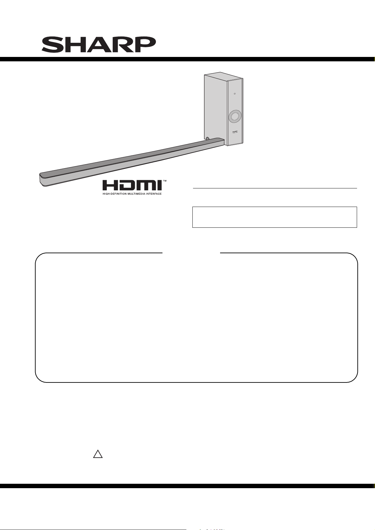
SOUND BAR HOME
THEATER SYSTEM
CONTENTS
PRECAUTIONS FOR USING LEAD-FREE SOLDER
CHAPTER 1. GENERAL DESCRIPTION
[1] Safety Precaution For Service Manual ..........1-1
[2] Important Service Notes (for U.K. only).........1-1
[3] Specifications ................................................1-1
[4] Name Of Parts............................................... 1-2
CHAPTER 2. MECHANISM DESCRIPTION
[1] Disassembly .................................................. 2-1
CHAPTER 3. MAJOR PART DRAWING
[1] Function Table Of IC...................................... 3-1
MODEL
HT-SL50 Sound Bar Home Theater system consisting of
Sound Bar and Subwoofer.
• In the interests of user-safety the set should be restored to its
original condition and only parts identical to those specified
be used.
CHAPTER 5. DIAGRAM
[1] Block Diagram................................................5-1
CHAPTER 6. CIRCUIT SCHEMATICS AND PARTS
LAYOUT
[1] Notes On Schematic Diagram .......................6-1
[2] Types Of Transistor And LED.........................6-1
[3] Schematic Diagram.........................................6-2
[4] Chart Of Connecting Wires.............................6-8
[5] Wiring Side Of PWB .......................................6-9
PARTS GUIDE
HT-SL50
CHAPTER 4. CIRCUIT DESCRIPTION
[1] Voltage .......................................................... 4-1
Parts marked with " " are important for maintaining the safety of the set. Be sure to replace these parts with
specified ones for maintaining the safety and performance of the set.
!
SHARP CORPORATION
This document has been published to be used
for after sales service only.
The contents are subject to change without notice.
Page 2
HT-SL50
PRECAUTIONS FOR USING LEAD-FREE SOLDER
1. Employing lead-free solder
"MAIN, SMPS, HDMI PWB" of this model employs lead-free solder. The LF symbol indicates lead-free solder, and
is attached on the PWB a nd service manuals. T h e a lphabetica l cha racter following LF shows the type of
lead-free solder.
Example:
Indicates lead-free solder of tin, silver and copper.
2. Using lead-free wire solder
When fixing the PWB soldered with the lead-free solder, apply lead-free wire solder. Repairing with conventional
lead wire solder may cause damage or accident due to cracks.
As the melting point of lead-free solder (Sn-Ag-Cu) is higher than the lead wire solder by 40°C, we recommend
you to use a dedicated soldering bit, if you are not familiar with how to obtain lead-free wire solder or soldering
bit, contact our service sta
Soldering
3.
As the melting point of lead-free solder (Sn-Ag-Cu) is about 220°C which is higher than the conventional lea d
solder by 40°C, and as it has poor solder wet ability, you may be apt to keep the soldering bit in contact with the
PWB for extended period of time. However, since the land may be peeled of for the maximum heat-resistance
temperat u re of parts may b e exceeded, remove the b it from the PWB as s oon as you confirm the s tea dy
soldering condition.
Lead-free solder contains more tin, and the end of the soldering bit may be easily corrected. Make sure to turn
on and off the power of the bit as required. If a different type of solder stays on the tip of the soldering bit, it is
alloyed with lead-free solder. Clean the bit after every use of it.
When the tip of the soldering bit is blackened during use, file it with steel wool or fine sand paper.
Be careful when replacing parts with pola
tion or service branch in your area.
rity indication on the PWB silk.
Lead-free wire solder for servicing
Ref No.
PWB-A 92LPWB8132MANS MAIN
PWB-B RUiTZA041AWZZ SMPS
PWB-C 92LPWB8131HDMS HDMI
Parts No.
Description
– i –
Page 3
HT-SL50
CHAPTER 1: GENERAL DESCRIPTION
[1] Safety Precaution For Service Manual
WARNING
This unit contains no user serviceable parts. Never remove covers unless qualified to do so.
This unit contains dangerous voltages, always remove mains plug from the socket before any service
operation and when not in use for a long period.
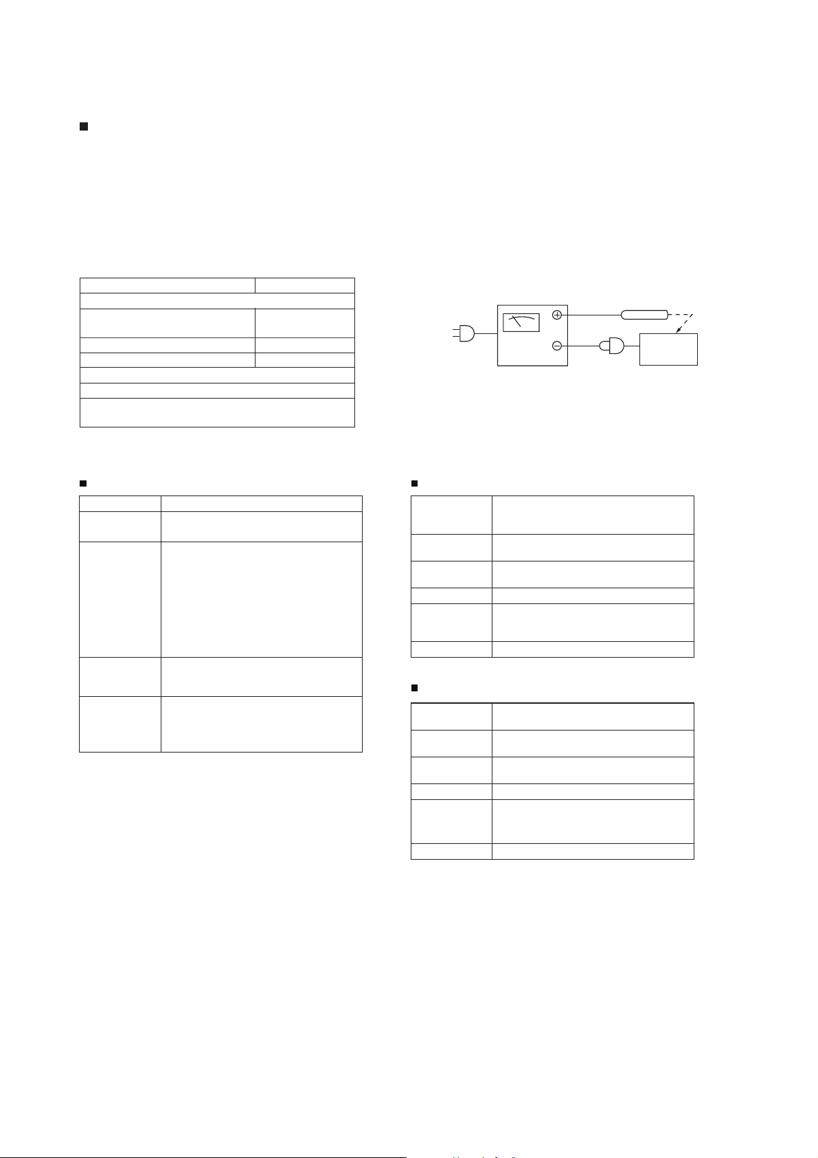
[2] Important Service Notes (for U.K. only)
Before returning the unit to the customer after completion of a repair or adjustment it is necessary for the following withstand voltage test to be
applied to ensure the unit is safe for the customer to use.
Setting of Withstanding Voltage Tester and set.
Set name set value
Withstanding Voltage Tester
Te st voltage 4,240 VPEAK
3,000 VRMS
Set time 6 secs
Set current (Cutoff current) 4 mA
Unit
Judgment
OK: The “GOOD” lamp lights.
NG: The “NG” lamp lights and the buzzer sounds.
WITHSTANDING
VOLTAGE TESTER
AC
SHORT-CIRCUIT
AC POWER
SUPPLY CORD
PROBE
OUT
UNIT
CONNECT THE PROBE
TO SHELL OF AUDIO LINE IN
[3] Specifications
General Soundbar speaker
Power source AC 220 - 240 V ~ 50/60 Hz
Power
consumption
Output power RMS: To t al 100 watts
Output
terminal
Input
terminal
Power On: 25 W
Power Stand-by: Below 1 W
RMS:
Front Left/Right:
RMS: 50W (25W + 25W) (10% T.H.D.)
RMS: 48W (24W + 24W) (1% T.H.D.)
Subwoofer:
RMS: 50W (10% T.H.D.)
RMS: 50W (1% T.H.D.)
HDMI™ (with Audio Return Channel)
output: (audio/video support to 1080p)
x 1
Analogue input (Audio in):
Stereo mini socket Ø 3.5 mm
HDMI input: (audio/video support to
1080p) x 1
Type Full Range speaker system
Maximum
input power
Rated input
power
Impedance 4 ohms/CH (3 pieces parallel)
Dimensions Width: 801 mm (31-1/2")
Weight 0.66 kg (1.46 lbs.)
2.2 x 11.5 cm (7/8" x 4-1/2")
Full Range
50 W/CH
25 W/CH
Height: 26 mm (1-1/16")
Depth: 50 mm (2")
Subwoofer
Type Subwoofer system
Maximum
input power
Rated input
power
Impedance 8 ohms
Dimensions Width: 115 mm (4 - 1/2")
Weight 4.50 kg (9.92 lbs.)
16 cm (6 - 5/16") woofer
100 W
50 W
Height: 422 mm (16 - 5/8")
Depth: 307 mm (12 - 1/16")
1 – 1
–2
Page 4
HT-SL50
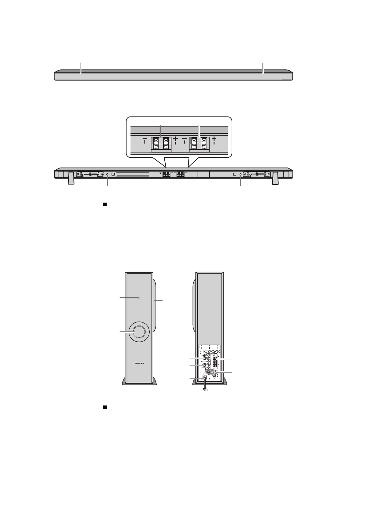
[4] Names Of Parts
1
FRONT VIEW
2
REAR VIEW
45
R
R
3 3
Sound Bar
1. Left Front Speaker
2. Right Front speaker
3. Bass Reflex Duct
4. Right Front Speaker terminal (Red/Black)
5. Left Front Speaker terminal (White/Black)
L
R
L
R
L
L
FRONT VIEW
1
3
2
ACTIVE SUBWOOFER SYSTEM
HT-SL50
Subwoofer
1. Stand-by Indicator
2. Bass Reflect Duct
3. Woofer
4. HDMI (TV ARC) Output Terminal
5. HDMI Input Terminal
6. AC Power Lead
7. Speaker Terminal
8. Audio In (TV) Terminal
REAR VIEW
4
5
6
7
8
1 – 2
– 2
Page 5
HT-SL50
CD-ES700/CD-ES77CD-ES700/CD-ES77Service ManualCD-ES700/CD-ES77MarketE
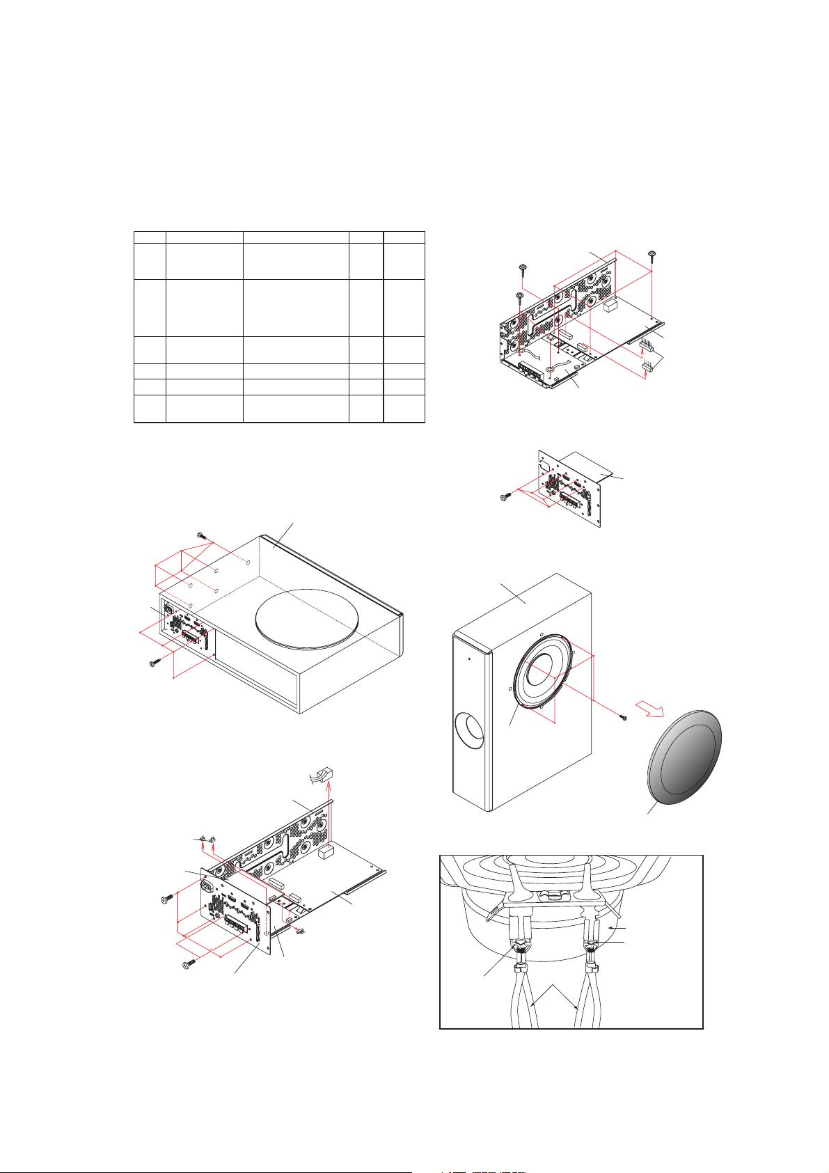
CHAPTER 2. MECHANISM DESCRIPTION
[1] Disassembly
Caution On Disassembly
Follow the below-mentioned notes when disassembling the unit and reassembling it, to keep it safe and ensure
excellent performance:
1. Be sure to remove the power supply plug from the wall outlet before starting to disassemble the unit.
2. Take off nylon bands or wire holders where they need to be removed when disassembling the unit. After servicing
the unit, be sure to rearrange the leads where they were before disassembling.
STEP
REMOVAL
1Main Chassis 1. Screw.........................
Rear Panel
2
with HDMI PWB
3SMPS PWB 1. Screw.........................
4Main PWB 1. Screw......................... (D1)x1 3
5 HDMI PWB 1. S
6 Subwoofer 1. Net Frame Ass'y........
PROCEDURE
2. Screw.........................
3. Socket........................
1. Screw.........................
2. Screw.........................
3. Screw.........................
4. Socket........................
5. AC Cord.....................
2. Socket........................
crew......................... (E1)x4 4
2. Screw.........................
(A1)x5
(A2)x4
(A3)x1
(B1)x4
(B2)x2
(B3)x2
(B4)x1
(B5)x1
(C1)x4
(C2)x2
(F1)x1
(F2)x4
FIGURE
1
1
2
2
2
3
2
2
3
5
(D1) x 1
Special Screw
(B3) x 2
Special Screw
Main Chassis
Main PWB
Figure 3
(C1) x 4
Special Screw
SMPS PWB
(C2) x 2
Rear Panel
(A2) x 4
M3.5 x 12mm
HDMI PWB
(A3) x 2
(A1) x 5
M4 x 10mm
Figure 1
Main Chassis
Wooden Box Ass’y
(B5) x 1
(E1) x 4
M3 x 8mm
Wooden Box Ass’y
Subwoofer
Figure 4
Figure 5
HDMI PWB
(F2) x 4
M4 x 16mm
(F1) x 1
Net Frame Ass’y
(B1) x 4
M3 x 6mm
(B2) x 2
M3 x 10mm
Rear Panel
Figure 2
Main PWB
(B4) x 1
SMPS PWB
2 – 1
SPEAKER UNIT
LOCKING TAB
SPEAKER
LOCKING TAB
WIRE
CAUTION:
TO REMOVE SPEAKER UNIT, PRESS THESE LOCKING TABS
TO RELEASE SPEAKER WIRES.
Page 6

HT-SL50
CHAPTER 3. MAJOR PART DRAWING
[1] Function Table Of IC
IC501 RH-IXA308AW00 : System Microcomputer (IXA308AW ) (1/3)
NAME
Pin
No.
PORT_TYPE
SCL
1
P3_5 / SCL / SSCK / (TRCIOD)
DIR_CKSEL
2
P3_4 / TRAO / SSO / RXD1 / (TXD1)
RESET
3
RESET
NO USE
4
XOUT / XC OUT / P4_7
GND
5
VSS / AVSS
NO USE
6
XIN / XCIN / P4_6
VCC
7
VCC / AVCC
MODE
8
MODE
SYS_PROTECT
9
P3_4 / INT0 / (RXD1)
NO USE
10
P1_7 / TRAIO / INT1
HDMI_INT
11
P3_6 / (TRD1) / (RXD1) / (INT1)
HDMI_RST
12
P3_1 / TRBO
AMP_OTW
13
P5_4 / TRCIOD
AMP_SD
14
P5_3 / TRCIOC
DIR_RST
15
P1_6 / CLK0 / (SSI)
DIR_ERROR
16
P1_5 / RXD0 / (TRAIO) / (INT1)
DIR_AUDIO
17
P1_4 / TXD0
DIR_FSOUT0
18
P1_3 / KI3 / AN11 / (TRBO)
DIR_FSOUT1
19
P1_2 / KI2 / AN10 / TRCIOB
VREF
20
VREF / P4_2
DAP_MUTE
21
P1_1 / KI1 / AN9 / TRCIOA /
TRCTRG
DAP_PWN
22
P1_0 / KI0 / AN8
DAP_RST
23
P3_3 / INT3 / SSI / TRCCLK
SDA
24
P3_4 / SDA / SCS / (TRCIOC)
DC_RELAY
25
P0_7 / AN0
NO USE
26
P0_6 / AN1
INPUT /
OUTPUT
OUTPUT
OUTPUT
INPUT INPUT OFF
OUTPUT
--- --- OFF GND
INPUT
--- --- OFF Supply input to micom (3.3V)
INPUT INPUT OFF Connect to VCC with 10kΩ resistor
INPUT INPUT OFF
OUTPUT
INPUT
OUTPUT
INPUT
INPUT
OUTPUT
INPUT
INPUT
INPUT
INPUT
--- --- OFF Reference Voltage for A/D converter
OUTPUT
OUTPUT
OUTPUT
INPUT /
OUTPUT
OUTPUT
OUTPUT
FORM
CMOS INPUT/
OUTPUT
CMOS INPUT/
OUTPUT
CMOS INPUT/
OUTPUT
CMOS INPUT/
OUTPUT
CMOS INPUT/
OUTPUT
CMOS INPUT/
OUTPUT
CMOS INPUT/
OUTPUT
CMOS INPUT/
OUTPUT
CMOS INPUT/
OUTPUT
CMOS INPUT/
OUTPUT
CMOS INPUT/
OUTPUT
CMOS INPUT/
OUTPUT
CMOS INPUT/
OUTPUT
CMOS INPUT/
OUTPUT
CMOS INPUT/
OUTPUT
CMOS INPUT/
OUTPUT
CMOS INPUT/
OUTPUT
CMOS INPUT/
OUTPUT
CMOS INPUT/
OUTPUT
CMOS INPUT/
OUTPUT
SOFT
PULL-UP
OFF I2C SERIAL CLOCK BUS LINE
OFF
OFF Connect to VCC with 10kΩ resistor
OFF Connect to VCC with 10kΩ resistor
OFF Set 'L'
OFF
OFF
OFF
OFF
OFF
OFF
OFF
OFF
OFF
OFF
OFF
OFF
OFF I2C SERIAL DATA BUS LINE
OFF
OFF
Selection of system clock source,
Low: PLL (VCO) clock, High: XTI clock
Reset Input. Active "L"
For MICOM reflash. Need 10k Pull-up
POWER SUPPLY ABNORMAL DETECTION
H : NORMAL , L : ABNORMAL
HDMI MODULE INTERRUPT DETECTION
H -> L
HDMI MODULE RESET CONTROL
H : NORMAL , L : RESET
AMPLIFIER OVERTEMPERATURE WARNING
DETECTION
H : NORMAL , L : ABNORMAL
AMPLIFIER SHUTDOWN DETECTION
H : NORMAL , L : ABNORMAL
DIR RESET CONTROL
H : NORMAL , L : RESET
DIR ERROR DETECTION
H : ERROR , L : NORMAL
DIR CHANNEL-STATUS DATA INFORMATION
H : OTHER , L : LINEAR PCM
DIR CALCULATED SAMPLING FREQUENCY OUTPUT 0
DIR CALCULATED SAMPLING FREQUENCY OUTPUT 1
DAP MUTE CONTROL
H : OFF , L : ON
DAP POWER DOWN CONTROL
H : NORMAL , L : POWER DOWN
DAP RESET CONTROL
H : NORMAL , L : RESET
DC RELAY CONTROL
H : ON , L : OFF
FUNCTION OUTLINE
3 – 1
Page 7
IC501 RH-IXA308AW00 : System Microcomputer (IXA308AW) (2/3)
HT-SL50
NAME
Pin
No.
PORT_TYPE
LED RED
27
P0_5 / AN2 / CLK1
LED BLUE
28
P0_4 / AN3 / TREO
HDMI_CE2
29
P0_3 / AN4
AREA
30
P0_2 / AN5
KEY
31
P0_1 / AN6
LEV_DET
32
P0_0 / AN7 / (TXD1)
INPUT /
OUTPUT
OUTPUT
OUTPUT
OUTPUT
INPUT
INPUT
INPUT
FORM
CMOS INPUT/
OUTPUT
CMOS INPUT/
OUTPUT
CMOS INPUT/
OUTPUT
CMOS INPUT/
OUTPUT
CMOS INPUT/
OUTPUT
CMOS INPUT/
OUTPUT
SOFT
PULL-UP
OFF
OFF
OFF HDMI Module Supply Control 1.8V
OFF
OFF
OFF Audio signal level detection
LED indicator.
STANDBY condition: H
LED indicator.
ON condition: H
H' : SL50
'L' :SL-70
When "L": Enter version check mode
During version check mode "L" : CLEAR ALL
FUNCTION OUTLINE
3 – 2
Page 8

HT-SL50
IC501 RH-IXA308AWZZ : System Microcomputer (IXA308AW) (3/3)
LEV_DET
AREA
HDMI_CE2
LED BLUE
LED RED
KEY
NO USE
DC_RELAY
32
31
29
30
28
P0_1 / AN6
P0_2 / AN5
P0_3 / AN4
SCL 1 )COICRT( / SCS / ADS / 4_3P)DOICRT( / KCSS / LCS / 5_3P 24 SDA
DIR_CKSEL
RESET
NO USE
GND
NO USE
VCC
MODE
2 P3_4 / TRAO / SSO / RXD1 / (TXD1)
3 RESET P1_0 / KI0 / AN8 22 DAP_PWN
4 GRTCRT / AOICRT / 9NA / 1IK / 1_1P7_4P / TUO CX / TUOX 21 DAP_MUTE
5 VSS / AVSS VREF / P4_2 20 VREF
6 XIN / XCIN / P4_6 P1_2 / KI2 / AN10 / TRCIOB 19 DIR_FSOUT1
7 VCC / AVCC P1_3 / KI3 / AN11 / (TRBO) 18 DIR_FSOUT0
8
MODE
P0_0 / AN7 / (TXD1)
P3_4 / INT0 / (RXD1)
P1_7 / TRAIO / INT1
P3_6 / (TRD1) /
9
10
NO USE
SYS_PROTECT
P0_4 / AN3 / TREO
IXA308A
P3_1 / TRBO
P5_4 / TRCIOD
(RXD1) / (INT1)
11
12
13
HDMI_INT
HDMI_RST
AMP_OTW
SHARP
25
27
26
P0_6 / AN1
P0_7 / AN0
P0_5 / AN2 / CLK1
P3_3 / INT3 / SSI / TRCCLK
P1_4 / TXD0
P5_3 / TRCIOC
P1_6 / CLK0 / (SSI)
(TRAIO) / (INT1)
P1_5 / RXD0 /
14
16
15
AMP_SD
DIR_RST
DIR_ERROR
23 DAP_RST
17
DIR_AUDIO
Figure 3-1 Block Diagram of IC
3 – 3
Page 9
CHAPTER 4. CIRCUIT DESCRIPTION
[1] Voltage
1. Main PWB
HT-SL50
IC301
PINNOVOLTAGE
(V)
1 10.500m 1 73.000m 1 1.490 1 220.000m
2 -0.000m 2 140.000m 2 1.440 2 -343.000m
3 0.405 3 154.000m 3 1.430 3 226.000m
4 2.400m 4 3.010 4 0.000m 4 139.000m
5 0.200m 5 0.000m 5 1.490 5 22.000m
693.900m 6 3.000 6 1.490
7 80.200m 7 3.011 7 1.490
8 76.000m 83.027 8 2.990
9 -45.200m 9 1.208
10 -104.200m 10 0.000m
11 302.000m 11 0.400m
12 66.200m 12 3.005
13 -151.200m 13 2.270 1 -210.000m 33 -112.000m
14 48.000m 14 2.280 2 -255.000m 34 49.300m
IC302
PINNOVOLTAGE
(V)
1 170.000m 19 3.027 7 -115.000m 39 175.000m
2 169.000m 20 3.030 8 -145.000m 40 136.000m
3 271.000m 21 0.000m 9 169.000m 41 235.000m
4 39.500m 22 0.000m 10 -266.000m 42 111.200m
5 31.400m 23 0.000m 11 -266.000m 43 201.000m
6153.800m 24 2.393 12 -134.000m 44 -317.000m
7 52.100m 25 0.000m 13 -107.000m 45 152.000m
8 56.300m 26 3.68714-138.000m 46 -117.000m
9 61.200m 27 2.052 15 -324.000m 47 -183.000m
10 78.200m 28 0.000m 16 94.000m 48 -332.000m
11 78.900m 29 3.023 17 -260.000m 49 -52.000m
12 3.300m 30 0.000m 18 -179.000m 50 -97.000m
133.300m 31 3.026 19 -210.000m 51 -152.000m
14 0.200m 32 0.412 20 -129.000m 52 -268.000m
000.381-81
19 368.000m 1 220.000m 25 53.000m 57 -208.000m
20 -205.000m 2 -343.000m 26 -241.000m 58 -262.000m
21 -125.000m 3 226.000m 27 -179.000m 59 -221.000m
22 -230.000m 4 139.000m 28 -221.000m 60 -160.000m
23 13.550m 5 22.000m 29 -181.000m 61 -380.000m
000.8252
27 -388.000m
28 -135.000m 1 177.000m
IC8
02
PINNOVOLTAGE
(V)
1 3.000 6 0.590
2 404.300m 7 -358.000m
3 -0.200m 8 -88.900m
44.300m
5 26.000m
IC501 IC502
PINNOVOLTAGE
(V)
15 -0.100m 3 -248.000m 35 -60.000m
16 87.800m 4 -225.000m 36 -142.000m
17 76.700m 5 -359.000m 37 242.000m
18 92.000m 6 -166.000m 38 296.000m
CN500
PINNOVOLTAGE
(V)
IC800
PINNOVOLTAGE
(V)
2 0.590
3 -412.000m
4 0.400m
5 -97.000m
PIN
NO
PIN
NO
VOLTAGE
(V)
IC601
VOLTAGE
(V)
2112m000.421-51
CN500
PINNOVOLTAGE
(V)
PINNOVOLTAGE
(V)
m000.231-35m000.0
m009.87-45m000.851-22m000.8261
m000.312-55m000.131-32m000.221-71
m000.082-65m000.903-42m
m000.821-26m000.851-03m000.391-42
m000.231-36m000.213-13m
m000.331-46m000.812-23m008.062
4 – 1
Page 10
HT-SL50
IC901
PINNOVOLTAGE
(V)
1 0.460 12 0.610 23 0.450 34 260.000m
2 2.270 13 0.610 24 265.000m 35 376.000m
3 0.000m 14 0.000m 25 0.000m 36 32.200m
4 0.000m 15 0.000m 26 242.000m 37 0.000m
5 2.280 16 0.000m 27 333.000m 38 0.000m
6 0.100m 17 38.800m 28 187.000m 39 175.000m
7 37.600m 18 0.000m 29 0.000m 40 375.000m
8 0.100m 19 3.314 300.000m 41286.000m
9 0.000m 20 3.024 31188.000m 42 0.000m
10 0.000m 21 3.206 32 375.000m 43 247.000m
11 0.610 22 3.500m 33 355.000m 44 0.450m
PIN
NO
VOLTAGE
(V)
PINNOVOLTAGE
(V)
PIN
NO
VOLTAGE
(V)
2. HDMI PWB
3CI2CI
PIN VOLTAGE PIN VOLTAGE PIN VOLTAGE
NO (V) NO (V) NO (V)
1 -049.300m 1 -3.410 13 -0.000m
2-48.200m 2 -3.360 14 -0.000m
3 -2.883 3 -4.520 15 -0.000m
4 -0.000m 4 -3.020 16 -3.020m
5 -2.895 5 -3.019 17 -0.000m
6 -0.100m 6 -3.000 18 -114.000m
7 -1.960 7 -4.900m 19 -1.474
8 -3.005 8 -3.03720-3.025
9 -0.300m 9 -2.000m 21 -0.100m
10 -3.005 10 -3.017 22 -3.870
11 -3.006 11 -3.000 23 -0.000m
12 -2.900m 12 -2.990 24 -0.000m
13 -0.100m
14 -50.200m
IC4
NO
VOLTAGE
(V)
PINNOVOLTAGE
(V)
1-3.018 17 -0.000m 33 -3.011 49 -0.300m
2 -2.93518 -0.777 34-3.012 50 -152.300m
3 -2.9
4 -2.141 20 -78.600m 36 -1.400m 52 -0.100m
5 -2.166 21 -1.500m 37-123.300m 53 -3.020m
6 -0.417 22 -1.300m 38 -43.000m 54 -50.300m
7 -0.493 23 -22.500m 39-3.021 55 -50.200m
8 -305.500m 24 -1.400m 40 -0.000m 56 -0.100m
9 -0.000m 25 -86.000m 41 -152.000m 57 -0.100m
10 -225.800m 26 -1.400m 42 -1.140 58 -3.023
11 -0.400m 27 -0.300m 43 -0.000m 59 -3.023
12 -3.020 28 -50.200m 44 -0.500m 60 -0.900m
13 -0.300m 29 -118.800m 45 -1.300m 61 -0.100m
14 -132.00m 30 -123.900m 46 -233.000m 62 -3.180
15 -1.300m 31 -2.000m 47 -102.100m 63 -2.113
16 -0.900m 32-
35 19 -1.500m 35 -1.400m 51 -142.000m
PIN
NO
VOLTAGE
(V)
3.018 48 -3.005 64 -3.025
PINNOVOLTAGE
(V)
PIN
4 – 2
Page 11
IC5
PINNOVOLTAGE
(V)
1 -2.920 17 -3.022 33 -0.100m 49 -1.223
2 -0.000m 18 -0.100m 34 -0.849 50 -200.000m
3 -0.900m 19 -3.021 35 -2.194 51 -0.100m
4 -0.000m 20 -3.02336 -0.100m 52 -0.200m
5 69.400m 21 -0.000m 37 -0.752 53 -0.300m
6-353.000m 22 -0.000m 38 -0.818 54 -3.900m
7 -0.750 23 -0.000m 39 -0.632 55 -0.000m
8 -1.230 24 -0.000m 40 -0.758 56 -0.300m
9 -2.990 25 -0.000m 41 -10.440m 57 -0.700m
10 -0.000m 26 -0.000m 42 -0.709 58 -0.500m
11 -127.000 27 -0.000m 43 -322.000 59 -1.100m
12 -130.00m 28 -0.000m 44 -0.100m 60 -0.000m
13 -0.100m 29 -0.000m 45 -3.035 61 -2.249
14 -0.930 30 -0.000m 46 -0.100m 62 -58.700m
15 -2.99831 -0.100m 47 -3.024 63 -0.100m
16 -0.000m 32-135.000m 48 -1.175 64 -2.165
PIN
NO
VOLTAGE
(V)
PINNOVOLTAGE
(V)
PIN
NO
VOLTAGE
(V)
HT-SL50
4 – 3
Page 12
HT-SL50
C
O
CHAPTER 5. DIAGRAMS
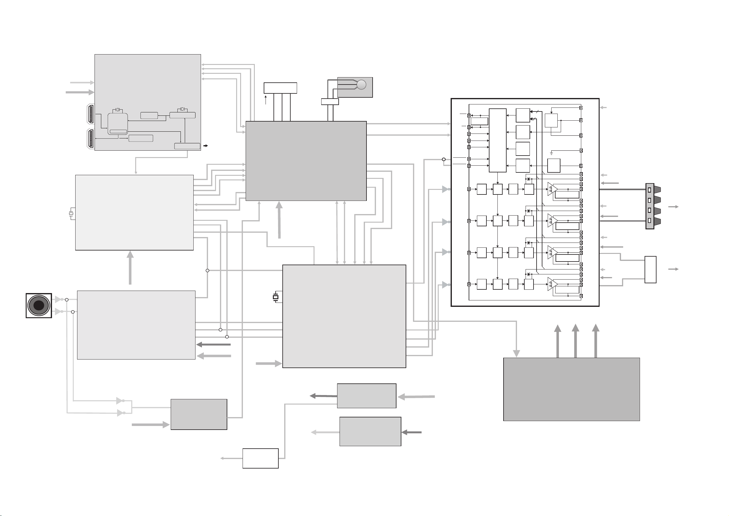
[1] Block Diagram
X301
12.288MHz
AUDIO IN
JK601
M0004AW
+1.8V
+3.3V UNSW
J3
HDMI IN
J7
HDMI OUT
XTO
XTI
Y3 (18.432MHZ)
5CI
K1A19PE
S/PDIF MUX
HDMI OUT/ARC ARC transceiver
SPDIF Output
DIR IC
DIR9001PW
VINR
VINL
HDMI PWB
I2C
S/PDIF
EP91H0
WIXR
IC302
CV/DDV
+3.3V
ADC IC
PCM1808
CI 3
C110FPE
HDMI RST
HDMI INT
Y2 (24MHZ)
I2C
IC4
Sub-MCU/EPF021A
J20
DIR AUDIO
DIR F
DIR FSOUT1
DIR ERR
DIR R
LR
B
K
D
SCKO
SCKI
DOUT
BCK
LRCK
VCC
D
SD
I2C from
host MCU
T
R
T
K
T
VD
SCL
TO/FROM MICOM
A
TO MAIN PWB
TO MICOM
FROM MICOM
+5V
+3.3V
MICOM FLASH
CN500
UNSW 3.3V
KEY
R5F21265SNFP
LEVEL DETECT
+3.3V UNSW
X601
13.5MHz
+3.3V
MODE
RESET
IC501
MICOM IC
VCC
MCLK
XTL_OUT
XTL_IN
SDIN1
SCLK
LRCLK
DVDD_PWM
CN700
FROM SUBWOOFER BOX
BICOLOR LED
LED_RD
LED GR
DC RELAY
SCL
SDA
SCL
SDA
SDIN2
DAP_PWDN
IC601
PWM IC
TAS5504A
FROM MICOM
FROM
MICOM
VALID
DAP RES
DAP_MUTE
PWM_P4
PWM_M4
PWM_P1
PWM_P2
AMP OTW
AMP SD
VALID
OTW
SD
M1
M2
M3
RESET_AB
RESET_CD
PWM_D
PWM_C
PWM_B
PWM_A
Internal Pullup
Resistors to VREG
PWM
Rcv.
PWM
Rcv.
PWM
Rcv.
PWM
Rcv.
IC901 STA5342L
4
Undervoltage
4
Protection
Power
On
Timing
Timing
Timing
Timing
Reset
Temp.
Sense
Overload
Protection
Gate
Drive
Gate
Drive
Gate
Drive
Gate
Drive
Protection
and
I/O Logic
Ctrl.
Ctrl.
Ctrl.
Ctrl.
VREG
sense
BTL/PBTL-Configuration
Pulldown Resistor
BTL/PBTL-Configuration
Pulldown Resistor
BTL/PBTL-Configuration
Pulldown Resistor
BTL/PBTL-Configuration
Pulldown Resistor
+12V
VDD
VREG
AGND
GND
OC_ADJ
GVDD_D
BST_D
PVDD_D
OUT_D
GND_D
GVDD_C
BST_C
PVDD_C
OUT_C
GND_C
GVDD_B
BST_B
PVDD_B
OUT_B
GND_B
GVDD_A
BST_A
PVDD_A
OUT_A
GND_A
UN_SW 3.9V
+28.4V
+12V
+12V
+12V
+12V
+12V
+28.4V
+28.4V
+28.4V
+28.4V
S0901
CNP301
sw-
12
sw+
L+
L-
R-
R+
TO SPEAKER
TO SUBWOOFER
INPUT
SIGNAL
+3.3V UNSW
NJR12094
IC502
OP-AMP
(LEVEL DETECT)
TO MICOM IC
LEVEL DETECT
TO HDMI
TO HDMI
+5V
+5V
+1.8V
IC800
5V REGULATOR
BD9329EF
+5V
IC802
HDMI CE2(1.8V)
+12V
UN_SW 3.9V
SMPS
MM3421JTRE
+3.3V
IC803
1117Y33
Figure 5-1: BLOCK DIAGRAM
5 – 1
Page 13

HT-SL50
CHAPTER 6. CIRCUIT SCHEMATICS AND PARTS LAYOUT
[1] Notes On Schematic Diagram
Resistor:
••
To differentiate the units of resistors, such symbol as
K and M are used: the symbol K means 1000 ohm
and the symbol M means 1000 kohm and the
resistor without any symbol is ohm-type resistor.
Besides, the one with “Fusible” is a fuse type.
Capacitor:
•
To indicate the unit of capacitor,
a symbol P is used:
this symbol P means pico-farad and the unit of the
capacitor without such a symbol is microfarad. As to
electrolytic capacitor, the expression “capacitance/
withstand voltage” is used.
(CH), (TH), (RH), (UJ): Temperature compensation
(ML): Mylar type
(P.P.): Polypropylene type
[2] Types Of Transistor And LED
Schematic diagram and Wiring Side of P.W.Board
for this model are subject to change for
improvement without prior notice.
The indicated voltage in each section is the one
•
measured by Digital Multimeter between such a
section and the chassis with no signal given.
•
Parts marked with “ ” are important for
maintaining the safety of the set. Be sure to replace
these parts with specified ones for maintaining the
safety and performance of the set.
C
(2)
TOP VIEW
(1) (2) (3)
1117Y33
TOP VIEW
1N4004
(1) (2) (3) (4) (5)
NM3421
TOP VIEW
DXA010
B
(3)
KRC104S
WEIV POTWEIV POT
E
(1)
6 – 1
Page 14

HT-SL50
[3] Schematic Diagram
MAIN PWB-A
AUDIO SIGNAL
TO
HDMI SECTION
B711AW
TO
LED
FOR
MICOM REFLASH
ONLY
A
B
C
D
+28.4V
E
L922
F
+28.4V
G
R995
0
GND1
H
1
2 3 456
Figure 6-1: MAIN SCHEMATIC DIAGRAM
7
8 9 10 11 12
6 – 2
Page 15

HT-SL50
B
C
D
E
F
G
A
H
HDMI PWB-C
HEAC0-
HEAC0+
3V3_HEAC
201209-300
101iB
A-BWP NIAM
B17
MORF
V5
C
5
u1u1
V5
01Cu101C
R
R
u1
HEAC0-
HEAC0+
AVDD
C64
47uF
J20
SPDIF CONNECTOR
1
3
2
2
0.1u
7K4
7K4
C65
44
AVSS
AVDD33
RXCP5RXCM4AVSS
C521
0.1u
TX_VDD18
C501
0.1u
40
41
43
38
42
39
TX2P
TX1P
TX0P
TX2M
TX1M
AVDD
RX1M11AVSS
RX0M7RX0P
AVDD33
6
8
9
10
C520
0.1u
TX_VDD18
C502
0.1u
34
35
37
36
TXCP
TX0M
AVDD
TXCM
K1A19PEK1A19PE
RX1P
RX2P15RX2M14AVDD
12
13
C519
0.1u
33
PVDD
VP SS VA/ SS
_TXE SGNI
AVSS
16
C503
0.1u
P2XT
M2XT
P1XT
M1XT
0XT
P
T
M0X
PCXT
MCXT
C504
0.1u
32
R522
31
W
30
CN
92
V_ SS
2
8
V
S
_ S
72
V_ SS
62
CN
RX_AVDD33 RX_AVDD33 RX_AVDD33
52
CN
42
CN
23
V_ SS
22
V_ SS
2
1
V_ SS
02
DVA
D
33
91
1devreser
81
CN
71
ER_TXE S
8
1DDVA_XR
R523
C518
0.1u
B100
C505
1u
TX_VDD18
270
1K
TX_VDD18
201209-300
R524
470
7J
P2XT
dlhs_2XT
M2XT
P1X
T
dlhs_1XT
M1XT
P0XT
dlhs_0X
T
M0XT
PCXT
dlhs_CXT
MCXT
CEC
+CAEH/LITU
S LC
S AD
DN
G
V5+
-CAEH/DPH
D
NG
DNG
DNG
DNG
A_IMDH
XT_IMDH
TUO IMDH
)CRA VT(
3V3
B101
201209-300
1V8
B102
201209-300
1V8
B103
201209-300
3V3
B104
201209-300
1V8
B105
201209-300
3V3
B106
201209-300
VDDE
C506
1u
VDD18
C508
47uF
TX_VDD18
C510
10uF
TX_AVDD33
C512
10uF
RX_AVDD18
C514
47uF
RX_AVDD33
C516
10uF
C507
0.1u
C509
0.1u
C511
0.1u
C513
0.1u
C515
0.1u
C517
0.1u
TX_AVDD33
VDD18
08R
0
-0CAEH
H
1
A_GLPT
8V
1C
3V3 CAEH_
RM202A0126CX
Am008
V61/Fu011CV61/Fu01
7C
u
1
B3
B3
T
021-902102
2Cu12C
021-902102
u1
M33 D
4B
02
1-902102
5B
021-902102
C3
4C
V61/Fu01C3V61/Fu01
u1.04Cu1.0
6B
DDCA_SCL
0
2
21-90210
8
C
u01
C
V61/F
DDCA_SDA
9
u1.0
U
1
U
1
1
NI
3
1R
1R
EC
7K
7K
4
4
NC
4
5
TUO
VSS
2
Am008
U
2
2
U
NI
EC
4
C0126CX 33 2
5
TUO
6C
6C
NC
VSS
2
NC
V61/F
V61/F
u01
u01
1
P
2XT
M2XT
P1X
M1
XT
1I
2
2
I
DNG
3
I3
4
4I
EXL S e-82
P0XT
M0XT
PCXT
MCXT
1
I
2
2I
DNG
NG
3
I3
4
4I
81U
1
EXL S e-820-4BBBT2
WOD S
N
R77
CEC
R78
OLCS ROTCE
OT
E
18
R
0
71U
DNG
D
8
1O
2O
O
3
4O
2
1O
2O
3
O
O
4
R74
P2XT
7
M2XT
6
P1XT
5
M1XT
BBBT
0-4
8
P
0XT
7
M0XT
6
PCX
T
5
MCX
T
0R75
0
C
CDD MAERT
0
RX_CEC [4]
0
TX_CEC [5]
NNOC IMDH
3V3
CEC
_CDD S 1L
_CDD1AD S 1AD
1
2
DNG
3
4
R87
10K
1
2
3
C
1I
2I
G
I
3
4I
1
2
3
4
5
6
7
8
9
1
0
11
21
91U
1
I
DNG
2I
S e-400-2BBBT1
EXL
01U
01U
DN
EXL
S e
CN
R84>
R83
R85
10K
CEC0_3V3
9
74
K
64R
94R
1
O
DD
2
O
CN
R86
10K
DDCA_SCL
DDCA_SDA
6
5
ES 1DDV_D
4
P00XR
M00XR
XR
R
M0CX
0
0
0
0
-400-2BBBT1
C57
1uF
C59
1uF
AVDD
R22
49.9
ARC_TX_EN
ARC_MODE
C66
0.1u
R20
5
R23
49.9
HEAC0_M
HEAC0_P
IC2
1
ARC_TX_EN
2
ARC_MODE
3
VDD
4
VSS
5
VDD
6
VSS
7
HEAC-
ARC_RX_EN
SPDIF_OUT
EP91H0
SPDIF_IN
RP+
BGRES
HEAC+
RP-
AVDD
R21
ECAFRETNI OIDUA
5
R24
R25
49.9
49.9
C58
1uF
RP0-
RP0+
14
13
12
11
10
9
8
R29
10K
R28
C60
1uF
33
PRG_SCL
PRG_SDA
MCU_SCL
MCU_SDA
CEC_RSTb
CECRX_PRG
CEC_INTb
R26
49.9
ARC_RX_EN
SPDIF_HDMI
SPDIF
bLTC_1TH
R704
50
_1P
TP2>
TP1
V5
R38
1
1
P
V5_1
R3
K01
_CDD S 1LC
3V3
1
2
3
4
5
6
7
8
9
10
11
8V1V5
RESET
IIC_SCL
IIC_SDA
HDMI_INT
SPDIF_HDMI
V5
A
1
DE
L
)DER(
DE
L
C
1
P02XR
2
R3K1R3
K1
M02XR
DN
G
3
P01XR
4
M01XR
_CDDS1AD
_CDD
S
S
_CDD
9U
9U
I
1
2I
DNG
I3
4I
L S-4BB
EX
BT2
6U
6U
1
1LC
1
I
2
3
2
I
L S e
8
1
O
7
2
O
6
R
O3
5
4O
0
-82
D
NG
V
EX
P02XR
02XR
M
01X
P
M01XR
e
DN_SCL [6]
DN_SDA [6]
LORTNO
R79 0
I 3
C
0OIPG
1OIPG
ICEC
_CDD S LC
_CDD S A
C
S L
S AD
RS bT
evreser
OIPG 3
OIPG
2
bT
NI
E
I
1O
DDV
2
O
07R
5
0
1O
2
O
O3
4O
]5[ GLPTH
V SS
D
_X
V S
C110FPEC110FP
06x0 = D
DDCA_SCL
6
5
4
DDCA_SDA
xr S LC
r S A
x
D
8
7
6
5
IB ST
DV
S
A
A
-820-4BBBT2
R511
2K2
C524
2.2uF
C72
C73
10uF 0.1u
42
3
2
6A
OCEC
D
TUO
NI_X
DDV
2
1A
0
CEC
22
12
02
9
1
8
1
1
7
6
1
5
1
41
13
V5
EXL S e-710-1AAA51
V5_1P
P00XR
M00XR
P0CXRP0C
M0CXR
C523
4.7n
MCU_SDA
MCU_SCL
HDMI IN
VDDE
VDD18
CEC0_3V3
C527
0.1u
81DDV
C525
0.1u
C522
0.1u
R509
10K
%
1
R89 27K
CEC [5]
CEC0_3V3
CLK24M1
C74 C75
1u 0.1u
LANOITPO
CE
C
2
1
1TROP
J3
G
DN
G
DN
DNG
G
DN
GULPTH
V5+
DNG_CDD
S AD
S LC
ER S DEVRE
CEC
-CXR
dlhs_C
XR
+CXR
-0XR
dlhs_0XR
R
+0X
-1XR
dlhs_1XR
+1XR
-2XR
dlhs_2XR
R
+2X
SPDIF
0XC8/0XCA
rxSDA
rxSCL
3V3
R510
10K
R526
R52500
CEC_P3V
TX2P
TX2M
TX1P
TX1M
TX0P
TX0M
TXCP
TXCM
EXL S
D2
23
22
21
20
91
81
71
1
6
1
5
41
13
21
11
01
9
8
7
6
5
4
3
2
1
15p
C528
15p
C526
R512 75
R501 22
R502 22
R503 22
R504 22
R505 22
R506 22
R507 22
R508 22
HTPLG
AAA
51
DDC_SDA1
DDC_SCL1
RX_CEC
RXC0P
RX00M
RX00P
RX10M
RX10P
RX20M
R519
4.7K
R518
4.7K
18.432M
R521
10K
5V
e-710-1
R45
1K
EP91A1K_RSTb
Y3
EE_SDA
EE_SCL
[5] TX_CEC
[3] HEAC0+
[5] DDCA_SCL
[5] DDCA_SDA
21
P1_5V
R702
10K
R513
10M
IICA
1D
P1_5V
S
D
RXC0M
C500
0.1u
94
05
1
5
25
5
3
SFI
45
55
II S_S KC
65
IIS W_ S
7
5
II S_S 0D
85
5
9
0
6
V SS
16
E S
26
63
46
RXC0M
RXC0P
RX00M
RX00P
RX10M
RX10P
RX20M
RX20P
R76
47K
2Q
G
BMK 3 P0D 30SA
5CI
TUO_X
LLP_DDV
DDV
DP
KLCM
_CDD S AD
_CDD S LC
_E
AD
_EE S LC
DDV
_UCM S AD
RX_AVDD18
10K10KR37
48
X_IN
A_CFX_LLP
MCU_SCL
1
47
46
VDD
EXT_RSTb
PVDD/AVDD
PVSS
2
3
RX_AVDD33
13
1
2
2
45
1
2
3
4
5
6
7
8
9
01
11
21
41
51
61
7
81
91
02
1
22
3
A_IMDH
1
2 3 456
7
8 9 10 11 12
Figure 6-2: HDMI SCHEMATIC DIAGRAM
6 – 3
Page 16

HT-SL50
HDMI PWB-C
M33D M33D
A
B
C
D
E
F
G
MCU Section
10K
R137
CECRX_PRG
CEC_RSTb
M33D
21
D4
D4
BAT54H
BAT54H
CEC_P3V
10K
R90
M33D
R94
1K
HT1_CTLb
EP91A1K_RSTb
ARC_RX_EN
ARC_MODE
PRG_SCL
PRG_SDA
HDMI_INT
M33D
DN_SCL
DN_SDA
C77>
0.1u
R102> 10K
R103 10K
C78>
0.1u
EPF021A_P62
EPF021A_P63
R95
1K
M33D
R96
1K
EPF021A_P70
EPF021A_P71
5V 5V
R113
2K
R97
CEC_INTb
C79
0.1u
M33D
M33D
R98
R99
2K R141
R114
2K
MCU_SCL
MCU_SDA
2K
M33D
1K
IIC_SCL
IIC_SDA
C80
0.1u
M33D
10K
R101 0
R104
10K
R110 0
R115 2K
R116 2K
CLOSE TO PAD
C76 15pC76 15p
C81 15pC81 15p
R700
4K7
R139
R140
10K
10K
R109
10K
ASCL1
1
M33D
R119 10K
R127 10K
R138
10K
ASDA1
1
49
50
51
52
53
54
55
56
57
58
59
60
61
62
63
64
DSCL1
MSCL1
XIM
24MHz
24MHz
Y2
Y2
XOM
IC4
P21
P22
P23
P24
P25
P26
P27
TIM0
TIM1
P10
P11
P12
P13
P70
P71
P40
1
1
R91
R91
10M
10M
M33D
TP3TP3
1
42
43
45
41
44
48
47
46
VSS
VDD
P8[1]
P8[0]
SPI_DO
X_IN
X_OUT
SPI_CLK
EPF021A/0.4mmEPF021A/0.4mm
P335P32
P41
P30
P31
P357VDD
P34
2
3
1
DSDA1
1
MSDA1
1
6
4
8
R88 56
R92
10K
R143
10K
P05
P04
P03
P02
P01
P00
P57
P56
P55
P54
P53
P52
P51
P50
R112
10K
RESET [3]
R515
10K
R144
10K
32
31
30
29
28
27
26
25
24
23
22
21
20
19
18
17
R106
EPF021A_OP0
R516
10K
R142
10K
35
34
38
40
39
VSS
VDD
ADC0
ADC1
VSSA
9
10
11
M33D
33
P07
P6136P6237P63
P60
P06
P7[4]/CIR
GND
VDDA
opm0
DP
RSTb15DM
16
14
12
13
10K
R145
10K
R107
10K
CLK24M1
M33D
1K
R100
6
R517
10K
2345
7
1
RP3
8P4R-10K
8
C82
0.1u
P1_PWR5V
HTPLG_A
ARC_TX_EN
3
4
5
6
5V
EPF021A_OP0
EPF021A_P71
EPF021A_P70
1
2
RP4
8P4R-10K
7
8
TXD
RXD
J8
5V
1
1
OP0
2
2
GND
3
3
TXD
4
4
RXD
5
5
FOR
FIRMWARE
FLASH ONLY
ICP
ADC0
ADC1
A_MUTE
H
1
2 3 456
R120
10K
M33D
R121
10K
R122
10K
7
8 9 10 11 12
Figure 6-3: MCU SCHEMATIC DIAGRAM
6 – 4
Page 17

[4] Chart Of Connectng Wires
A
B
TO
SPEAKER SYSTEM
LINE INPUT
FOR
EXTERNAL MICOM
REFLASH ONLY
HT-SL50
SUBWOOFER
C
D
BICOLOR LED
E
TO
TO
BK
RD
GR
WH
RD
12
CNS301
CNS700
12
RDBKBK
12345
CN500
Bi101
GY
GY
GY
GY
GY
GY
GY
GY
GY
GY
RD
Bi801
BK
Bi800
RD
BRBRBRBRBRBRBR
BR
CNS101
2 3 4567891011
1
J20
2 3 4567891011
1
HDMI OUT HDMI IN
TV ARC
J7
J3
HDMI PWB-C
FOR
FIRMWARE FLASH
ONLY
J8
CON2CON3
CON1
21
F
2
1
BL BR
CNS800
BK
SMPS PWB-B
AC POWER SUPPLY CORD
G
H
1
23456
CNS801
7
Figure 6-4: WIRING CONNECTION
8 9 10 11 12
AC 220 - 240V ~ 50/60Hz
COLOR TABLE
RD
BK
WH
GY GRAY
BL BLUE
GR GREEN
BR BROWN
RED
BLACK
WHITE
6 – 5
Page 18

HT-SL50
[5] Wiring Side Of PWB
A
MAIN PWB-A
B
543 21
C
12
D
10 11 12
E
12 3 45678 9
12
F
3
12
3
4
12 3 4567 89
10
TOP VIEW BOTTOM VIEW
G
Lead-free solder indication
H
Lead-free solder is used in the MAIN PWB.
Refer to "Precautions for handling lead-free solder" for instructions
and precautions.
1
2 3 456
7
Figure 6-5: WIRING SIDE OF MAIN PWB
8 9 10 11 12
6 – 6
Page 19

HT-SL50
A
B
C
D
HDMI PWB-C
111
E
12345
F
G
Lead-free solder indication
Lead-free solder is used in the HDMI PWB.
H
Refer to "Precautions for handling lead-free solder" for instructions
and precautions.
TOP VIEW BOTTOM VIEW
1
2 3 456
Figure 6-6: WIRING SIDE OF HDMI PWB
7
8 9 10 11 12
6 – 7
Page 20

HT-SL50
-MEMO-
6 – 8
Page 21

PARTS GUIDE
SOUND BAR HOME
THEATER SYSTEM
HT-SL50
CONTENTS
[1] INTEGRATED CIRCUITS
[2] TRANSISTORS
[3] DIODES
[4] COILS
[5] CRYSTALS / VIBRATORS
[6] CAPACITORS
Explanation of capacitors/resistors parts codes
Capacitors
VCC ....................... Ceramic type
VCK ........................ Ceramic type
VCT ........................ Semiconductor type
VC • • MF ............... Cylindrical type (withoutleadwire)
VC • • MN ............... Cylindrical type (withoutleadwire)
VC • • TV ................ Square type (withoutleadwire)
VC • • TQ ............... Square type (withoutlead wire)
VC • • CY ............... Square type (withoutleadwire)
VC • • CZ ............... Square type (withoutlead wire)
VC•••••••••J..The13th character represents capacity difference.
("J" ±5%, "K" ±10%, "M" ±20%, "N" ±30%,
"C" ±0.25 pF, "D" ±0.5 pF, "Z" +80-20%.)
If there are no indications for the electrolytic capacitors,erroris ±20%.
MODEL
HT-SL50 Sound Bar Home Theater system consisting
of Sound Bar and Subwoofer.
HT-SL50
[7] RESISTORS
[8] OTHER CIRCUITRY PARTS
[9] CABINET PARTS /
SUBWOOFER PARTS
[10] ACCESSORIES / PACKING PARTS
[11] P.W.B. ASSEMBLY
Resi s tors
VRD ....................... Carb on-film type
VRS ........................ Carbon-film type
VRN ....................... Metal-film type
VR • • MF ............... Cylindrical type (withoutleadwire)
VR • • MN ............... Cylindrical type (withoutlead wire)
VR • • TV ................ Square type (withoutlead wire)
VR • • TQ ............... Square type (withoutlea dwire)
VR • • CY ............... Square type (withoutleadwire)
VR • • CZ ............... Square type (withoutlea dwire)
VR•••••••••J..The13th character represents error.
("J" ±5%, "F" ±1%, "D" ±0.5%.)
If there are no indications for other parts,theresistorsare ±5%
carbon-film type.
Explanation of PWB Assembly parts code category
S Category -- Repair ( Component parts of PWB can be replace and repair, PWB no supply )
X Category -- Replacement ( PWB can not be repair. Component parts no supply )
S.X Category -- Repair and Replacement ( PWB can repair and replace )
KG Category -- Revolve repair by Business Center ( Return to Business Center and repair by ma nufacturer. Component parts no supply )
Parts marked with " " are important for maintaining the safety of the set. Be sure to replace these parts with specified
ones for maintaining the safety and performance of the set.
!
SHARP CORPORATION
This document has been published to be used
for after sales service only.
The contents are subject to change without notice.
Page 22

HT-SL50
NO. PARTS CODE
PRICE
RANK
[1] INTEGRATED CIRCUITS
iC2 VHiEP91H0++-1 AP HDMI 1.4 Audio Return Channel Transceiver
iC3 VHiEPF011C+-1 AP Generic MCU with 64K Embedded Flash
iC4 RH-IXA310AW00 AP HDMI iC
iC5 VHiEP91A1K+-1 AX HDMI 1.3 1 Out Repeater with Audio Output
iC301 VHiPCM1808P-1 AH Single Ended Analog
iC302 VHiDiR9001P-1 AU DIR9001PWR 96kHz
iC501 RH-iXA308AW00 AR System Microcomputer,iXA308AW
iC502 VHINJM12904-1 AE Operational Amplifier
iC601 VHITAS5504A-1 AR Audio Processor
iC800 VHIBD9329EF-1 AG Voltage Regulator
iC802 VHi3421JTRE-1 AE Voltage Regulator,1.8V
iC803 VHiUTC1117Y33 AD Voltage Regulator, 3.3V
iC901 VHiTAS5342L-1 AR Digital Amplifier
[2] TRANSISTORS
Q2 VSKMB3DP30S-1 AD Switching Transistor
Q802 VSKRC104S//-1 AC Digital,NPN,KRC104 S
[3] DIODES
D1 RH-VXA005AFZZ AC Array Diode
D2 RH-VXA005AFZZ AC Array Diode
D4 VHDBAT54H++-1 AB Schotty Barrier
D303 VHDDA1010++-1 AB Silicon,DA1010
D304 VHDDA1010++-1 AB Silicon,DA1010
D502 VHDGD1N4004-1 AB Silicon,D1N4004
D530 VHDDA1010++-1 AB Silicon,DA1010
D560 VHDDA1010++-1 AB Silicon,DA1010
D561 VHDDA1010++-1 AB Silicon,DA1010
D803 VHDDA1010++-1 AB Silicon,DA1010
D805 VHDDA1010++-1 AB Silicon,DA1010
D806 VHDDA1010++-1 AB Silicon,DA1010
D809 VHDDA1010++-1 AB Silicon,DA1010
D810 VHDDA1010++-1 AB Silicon,DA1010
D820 VHDDA1010++-1 AB Silicon,DA1010
U6 RH-VXA007AFZZ AD Array
U9 RH-VXA003AWZZ AD Array
U10 RH-VXA003AWZZ AD Array
U17 RH-VXA003AWZZ AD Array
U18 RH-VXA003AWZZ AD Array
U19 RH-VXA007AFZZ AD Array
ZD563 RH-EXA686WJQZ AB Zener,3.3V
ZD807 RH-EXA716WJQZ AB Zener
ZD811 RH-EXA701WJQZ AB Zener,6.8V
ZD813 VHDGDSK32A+-1 AD Silicon,DGDSK32A
ZD814 VHDGDSK32A+-1 AD Silicon,DGDSK32A
[4] COILS
B4 RBLN-0253TAZZ AA Ferrite Bead
B6 RBLN-0253TAZZ AA Ferrite Bead
B100 RBLN-A009AWZZ AA Ferrite Bead, 300ohms
B101 RBLN-A009AWZZ AA Ferrite Bead, 300ohms
B102 RBLN-A009AWZZ AA Ferrite Bead, 300ohms
B103 RBLN-A009AWZZ AA Ferrite Bead, 300ohms
B104 RBLN-A009AWZZ AA Ferrite Bead, 300ohms
B105 RBLN-A009AWZZ AA Ferrite Bead, 300ohms
B106 RBLN-A009AWZZ AA Ferrite Bead, 300ohms
B17 RBLN-A009AWZZ AA Ferrite Bead, 300ohms
FB300 RBLN-A010AWZZ AA Chip Ferrite Core
FB301 RBLN-A010AWZZ AA Chip Ferrite Core
FB304 RBLN-A010AWZZ AA Chip Ferrite Core
FB313 RBLN-0077TAZZ AB Ferrite Bead
FB314 RBLN-0077TAZZ AB Ferrite Bead
FB601 RFILN5044NCPZ AB Ferrite Bead
FB602 RFILN5044NCPZ AB Ferrite Bead
FB603 RFILN5044NCPZ AB Ferrite Bead
L830 RCILCA029WJZZ AD Coil
L921 RCILZA074AWZZ AF Coil, 22mH Peaking
L922 RCILZA074AWZZ AF Coil, 22mH Peaking
L923 RCILZA074AWZZ AF Coil, 22mH Peaking
L924 RCILZA074AWZZ AF Coil, 22mH Peaking
L930 RCILZ0055AWZZ AH Coil
L931 RCILZ0055AWZZ AH Coil
L932 RCILZ0055AWZZ AH Coil
RF1 RCORFA015AWZZ AD Ring Ferrite Core
[5] CRYSTALS / VIBRATORS
X301 RCRSCA145WJZZ AE Crystal, 12.2880MHz
X601 RCRSPA030AWZZ AD Crystal, 13.5MHz
Y2 RCRSPA032AWZZ AE Crystal, 24MHz
Y3 RCRSPA031AWZZ AE Crystal, 18.432MHz
[6] CAPACITORS
C57 VCKYCY1EB105K AB 1 µF,50V
C58 VCKYCY1EB105K AB 1 µF,50V
C59 VCKYCY1EB105K AB 1 µF,50V
C60 VCKYCY1EB105K AB 1 µF,50V
NEW
MARK
PA RT
RANK
DESCRIPTION
1
Page 23

NO. PARTS CODE
PRICE
RANK
NEW
MARK
PA RT
RANK
[6] CAPACITORS
C64 RC-KZ3035AWZZ AE 47 µF,10V,Electrolytic
C65 VCKYCY1HB104K AD 0.1 µF,50V
C66 VCKYCY1HB104K AD 0.1 µF,50V
C72 RC-KZA110WJZZ AD 10 µF,25V
C73 VCKYCY1HB104K AD 0.1 µF,50V
C74 VCKYCY1EB105K AB 1 µF,50V
C75 VCKYCY1HB104K AD 0.1 µF,50V
C76 VCCCCY1HH330J AA 33 pF (CH),50V
C77 VCKYCY1HB104K AD 0.1 µF,50V
C78 VCKYCY1HB104K AD 0.1 µF,50V
C79 VCKYCY1HB104K AD 0.1 µF,50V
C80 VCKYCY1HB104K AD 0.1 µF,50V
C81 VCCCCY1HH330J AA 33 pF (CH),50V
C82 VCKYCY1HB104K AD 0.1 µF,50V
C300 VCKYCZ1EB682K AA 6800 pF,25V
C301 VCKYCZ1EB682K AA 6800 pF,25V
C302 VCKYCZ1HB331K AB 330 pF,50V
C303 VCKYCZ1HB331K AB 330 pF,50V
C304 VCKYCY1HB104K AD 0.1 µF,50V
C305 VCEAEA1CW106M AB 10 µF,16V,Electrolytic
C306 VCEAEA1CW106M AB 10 µF,16V,Electrolytic
C311 VCKYCY1HB104K AD 0.1 µF,50V
C312 VCEAEA1CW106M AB 10 µF,16V,Electrolytic
C313 VCKYCY1HB104K AD 0.1 µF,50V
C314 VCEAZA1CW336M AB 33 µF,16V,Electrolytic
C315 VCKYCY1HB104K AD 0.1 µF,50V
C316 VCEAZA1CW107M AC 100 µF,16V,Electrolytic
C318 VCTYPA1HF104Z AB 0.1 µF,50V
C337 VCCCCZ1HH180J AA 18 pF (CH),50V
C338 VCCCCZ1HH150J AA 15 pF (CH),50V
C340 VCKYCY1EB105K AB 1 µF,25V
C352 VCKYCY1HB683K AB 0.068 pF,50V
C353 VCKYCZ1EB472K AB 4700 pF,25V
C500 VCKYCY1HB104K AD 0.1 µF,50V
C501 VCKYCZ1EB104K AA 0.1 µF,25V [Use in MAIN PWB-A]
C501 VCKYCY1HB104K AD 0.1 µF,50V [Use in HDMI PWB-C]
C502 VCKYCY1HB104K AD 0.1 µF,50V
C503 VCKYCY1HB104K AD 0.1 µF,50V
C504 VCKYCY1HB104K AD 0.1 µF,50V
C505 VCKYCY1EB105K AB 1 µF,50V
C506 VCKYCY1EB105K AB 1 µF,50V
C507 VCKYCY1HB104K AD 0.1 µF,50V
C508 RC-KZ3035AWZZ AE 47 µF,10V
C509 VCKYCY1HB104K AD 0.1 µF,50V
C510 RC-KZA110WJZZ AD 10 µF,25V
C511 VCKYCY1HB104K AD 0.1 µF,50V
C512 RC-KZA110WJZZ AD 10 µF,25V
C513 VCKYCY1HB104K AD 0.1 µF,50V
C514 RC-KZ3035AWZZ AE 47 µF,10V
C515 VCKYCY1HB104K AD 0.1 µF,50V
C516 RC-KZA110WJZZ AD
C517 VCKYCY1HB104K AD 0.1 µF,50V
C518 VCKYCY1HB104K AD 0.1 µF,50V
C519 VCKYCY1HB104K AD 0.1 µF,50V
C520 VCKYCY1HB104K AD 0.1 µF,50V
C521 VCKYCY1HB104K AD 0.1 µF,50V
C522 VCKYCY1HB104K AD 0.1 µF,50V
C523 VCKYCY1HB472K AA 4700 pF,50V
C524 RC-KZA211WJZZ AB 2.2 µF
C525 VCKYCY1HB104K AD 0.1 µF,50V
C526 VCCCCY1HH330J AA 33 pF (CH),50V
C527 VCKYCY1HB104K AD 0.1 µF,50V
C528 VCCCCY1HH330J AA 33 pF (CH),50V
C530 VCEAEA1HW105M AB 1 µF,50V,Electrolytic
C550 VCEAEA1HW105M AB 1 µF,50V,Electrolytic
C551 VCCCCZ1HH150J AA 15 pF (CH),50V
C552 VCCCCZ1HH150J AA 15 pF (CH),50V
C553 VCCCCZ1HH150J AA 15 pF (CH),50V
C554 VCCCCZ1HH150J AA 15 pF (CH),50V
C565 VCKYCZ1EB104K AA 0.1 µF,25V
C568 VCKYTV1EF104Z AA 0.1 µF,25V
C569 VCKYCZ1AB105K AA 1 µF,10V
C570 VCKYCZ1EB104K AA 0.1 µF,25V
C571 VCKYCZ1EB104K AA 0.1 µF,25V
C572 VCEAEA1CW476M AB 47 µF,16V,Electrolytic
C601 VCKYCZ1EB104K AA 0.1 µF,25V
C602 VCKYCZ1EB103K AA 0.01 µF,25V
C603 VCKYCZ1EB104K AA 0.1 µF,25V
C604 VCKYCZ1EB104K AA 0.1 µF,25V
C605 VCKYCZ1EB103K AA 0.01 µF,25V
C607 VCKYCZ1EB104K AA 0.1 µF,25V
C608 VCKYCZ1EB104K AA 0.1 µF,25V
C609 VCEAEA1CW106M AB 10 µF,16V,Electrolytic
C610 VCKYCZ1HB102K AB 1000 pF,50V
C615 VCEAEA1CW106M AB 10 µF,16V,Electrolytic
C616 VCKYCZ1EB104K AA 0.1 µF,25V
C617 VCKYCZ1EB104K AA 0.1 µF,25V
C619 VCCCCZ1HH300J AB 30 pF (CH),50V
C620 VCCCCZ1HH300J AB 30 pF (CH),50V
10 µF,25V
2
HT-SL50
DESCRIPTION
Page 24

HT-SL50
NO. PARTS CODE
PRICE
RANK
[6] CAPACITORS
C621 VCTYPA1HF104Z AB 0.1 µF,50V
C622 VCKYPA1HB222K AA 2200 pF,50V
C624 VCCCCZ1HH390J AB 39 pF,50V
C625 VCCCCZ1HH390J AB 39 pF,50V
C633 VCKYCZ1EB104K AA 0.1 µF,25V
C636 VCKYCZ1EB104K AA 0.1 µF,25V
C648 VCKYCZ1EB104K AA 0.1 µF,25V
C653 VCKYCZ1EB104K AA 0.1 µF,25V
C804 VCKYCZ1EB104K AA 0.1 µF,25V
C808 VCEAEA1CW226M AB 22 µF,16V,Electrolytic
C809 VCKYCZ1EB104K AA 0.1 µF,25V
C820 VCEAEA1CW226M AB 22 µF,16V,Electrolytic
C821 VCKYCZ1EB104K AA 0.1 µF,25V
C822 VCKYCZ1EB104K AA 0.1 µF,25V
C830 VCKYCZ1EB104K AA 0.1 µF,25V
C831 RC-KZA110WJZZ AD 10 µF,25V
C833 RC-KZ3028AWZZ AE 22 µF,16V
C836 VCKYCZ1HB222K AB 2200 pF,50V
C838 VCKYCZ1EB104K AA 0.1 µF,25V
C850 VCEAZA1CW227M AC 220 µF,16V,Electrolytic
C901 VCKYCZ1EB104K AA 0.1 µF,25V
C910 VCEAEA1CW106M AB 10 µF,16V,Electrolytic
C912 VCKYCZ1EB104K AA 0.1 µF,25V
C921 VCKYCZ1EB104K AA 0.1 µF,25V
C922 VCKYCZ1EB104K AA 0.1 µF,25V
C923 VCKYCZ1EB104K AA 0.1 µF,25V
C924 VCKYCY1HB333K AB 0.033 µF,50V
C927 VCKYCZ1EB104K AA 0.1 µF,25V
C932 VCKYCZ1EB104K AA 0.1 µF,25V
C933 VCKYCY1HB333K AB 0.033 µF,50V
C934 VCKYCY1HB333K AB 0.033 µF,50V
C935 VCKYCZ1EB104K AA 0.1 µF,25V
C940 VCKYCZ1EB104K AA 0.1 µF,25V
C943 VCKYCY1HB333K AB 0.033 µF,50V
C944 VCKYCZ1EB104K AA 0.1 µF,25V
C950 VCEAZA1HW107M AC 100 µF,50V,Electrolytic
C951 VCEAZA1HW107M AC 100 µF,50V,Electrolytic
C952 VCKYCZ1EB104K AA 0.1 µF,25V
C953 VCKYCZ1EB104K AA 0.1 µF,25V
C954 VCKYCZ1EB103K AA 0.01 µF,25V
C955 VCKYCZ1EB103K AA 0.01 µF,25V
C960 VCKYCY1CB474K AB 0.47 µF,16V
C961 VCKYCZ1EB104K AA 0.1 µF,25V
C962 VCKYCZ1EB104K AA 0.1 µF,25V
C963 VCKYCZ1HB102K AB 1000 pF,50V
C964 VCKYCZ1HB102K AB 1000 pF,50V
C965 VCKYCZ1EB103K AA 0.01 µF,25V
C966 VCKYCZ1EB103K AA 0.01 µF,25V
C980 VCEAZA1HW107M AC 100 µF,50V,Electrolytic
C981 VCEAZA1HW107M AC 100 µF,50V,Electrolytic
C982 VCEAZA1HW107M AC
C983 VCEAZA1HW107M AC 100 µF,50V,Electrolytic
C984 VCKYCZ1AB105K AA 1 µF,10V
C985 VCKYCZ1AB105K AA 1 µF,10V
C986 VCKYCZ1EB104K AA 0.1 µF,25V
C987 VCKYCZ1EB104K AA 0.1 µF,25V
C988 VCKYCZ1EB104K AA 0.1 µF,25V
C989 VCKYCZ1EB104K AA 0.1 µF,25V
C990 VCKYCZ1EB103K AA 0.01 µF,25V
C991 VCKYCZ1EB103K AA 0.01 µF,25V
C992 VCKYCZ1EB103K AA 0.01 µF,25V
C993 VCKYCZ1EB103K AA 0.01 µF,25V
C994 VCKYCY1HB104K AD 0.1 µF,50V
C995 VCKYCY1HB104K AD 0.1 µF,50V
C996 VCKYCY1HB104K AD 0.1 µF,50V
C997 VCCCCZ1HH330J AB 33 pF (CH),50V
[7] RESISTORS
R20 VRSCY2AF4R99F AA 4.99 ohm,1/16W
R21 VRSCY2AF4R99F AA 4.99 ohm,1/16W
R22 VRSCY1JB49R9F AA 49.9 ohm,1/16W
R23 VRSCY1JB49R9F AA 49.9 ohm,1/16W
R24 VRSCY1JB49R9F AA 49.9 ohm,1/16W
R25 VRSCY1JB49R9F AA 49.9 ohm,1/16W
R26 VRSCY1JB49R9F AA 49.9 ohm,1/16W
R28 VRS-CY1JB330J AA 33 ohm,1/16W
R29 VRS-CY1JB103F AA 10 kohm,1/16W
R37 VRS-CY1JB103F AA 10 kohm,1/16W
R38 VRS-CY1JB103F AA 10 kohm,1/16W
R39 VRS-CY1JB473J AA 47 kohm,1/16W
R45 VRS-CY1JB102F AA 1 kohm,1/16W
R46 VRS-CY1JB000J AA 0 ohms,Jumper,0.8X1.55mm
R49 VRS-CY1JB000J AA 0 ohms,Jumper,0.8X1.55mm
R74 VRS-CY1JB000J AA 0 ohms,Jumper,0.8X1.55mm
R75 VRS-CY1JB000J AA 0 ohms,Jumper,0.8X1.55mm
R76 VRS-CY1JB473J AA 47 kohm,1/16W
R77 VRS-CY1JB000J AA 0 ohms,Jumper,0.8X1.55mm
R78 VRS-CY1JB000J AA 0 ohms,Jumper,0.8X1.55mm
NEW
MARK
PA RT
RANK
100 µF,50V,Electrolytic
DESCRIPTION
3
Page 25

NO. PARTS CODE
PRICE
RANK
NEW
MARK
PA RT
RANK
[7] RESISTORS
R79 VRS-CY1JB000J AA 0 ohms,Jumper,0.8X1.55mm
R80 VRS-CY1JB000J AA 0 ohms,Jumper,0.8X1.55mm
R81 VRS-CY1JB000J AA 0 ohms,Jumper,0.8X1.55mm
R83 VRS-CY1JB000J AA 0 ohms,Jumper,0.8X1.55mm
R84 VRS-CY1JB000J AA 0 ohms,Jumper,0.8X1.55mm
R85 VRS-CY1JB103F AA 10 kohm,1/16W
R86 VRS-CY1JB103F AA 10 kohm,1/16W
R87 VRS-CY1JB103F AA 10 kohm,1/16W
R88 VRS-CY1JB560J AA 56 ohm,1/16W
R89 VRS-CY1JB273F AA 27 kohm,1/16W
R90 VRS-CY1JB103F AA 10 kohm,1/16W
R91 VRS-CY1JB106F AA 10 Mohm,1/16W
R92 VRS-CY1JB103F AA 10 kohm,1/16W
R94 VRS-CY1JB102F AA 1 kohm,1/16W
R95 VRS-CY1JB102F AA 1 kohm,1/16W
R96 VRS-CY1JB102F AA 1 kohm,1/16W
R97 VRS-CY1JB102F AA 1 kohm,1/16W
R98 VRS-CY1JF202F AA 2 kohm,1/16W
R99 VRS-CY1JF202F AA 2 kohm,1/16W
R100 VRS-CY1JB102F AA 1 kohm,1/16W
R101 VRS-CY1JB000J AA 0 ohms,Jumper,0.8X1.55mm
R102 VRS-CY1JB103F AA 10 kohm,1/16W
R103 VRS-CY1JB103F AA 10 kohm,1/16W
R104 VRS-CY1JB103F AA 10 kohm,1/16W
R106 VRS-CY1JB103F AA 10 kohm,1/16W
R107 VRS-CY1JB103F AA 10 kohm,1/16W
R109 VRS-CY1JB103F AA 10 kohm,1/16W
R110 VRS-CY1JB000J AA 0 ohms,Jumper,0.8X1.55mm
R112 VRS-CY1JB103F AA 10 kohm,1/16W
R113 VRS-CY1JF202F AA 2 kohm,1/16W
R114 VRS-CY1JF202F AA 2 kohm,1/16W
R115 VRS-CY1JF202F AA 2 kohm,1/16W
R116 VRS-CY1JF202F AA 2 kohm,1/16W
R119 VRS-CY1JB103F AA 10 kohm,1/16W
R120 VRS-CY1JB103F AA 10 kohm,1/16W
R121 VRS-CY1JB103F AA 10 kohm,1/16W
R122 VRS-CY1JB103F AA 10 kohm,1/16W
R127 VRS-CY1JB103F AA 10 kohm,1/16W
R137 VRS-CY1JB103F AA 10 kohm,1/16W
R138 VRS-CY1JB103F AA 10 kohm,1/16W
R139 VRS-CY1JB103F AA 10 kohm,1/16W
R140 VRS-CY1JB103F AA 10 kohm,1/16W
R141 VRS-CY1JB103F AA 10 kohm,1/16W
R142 VRS-CY1JB103F AA 10 kohm,1/16W
R143 VRS-CY1JB103F AA 10 kohm,1/16W
R144 VRS-CY1JB103F AA 10 kohm,1/16W
R145 VRS-CY1JB103F AA 10 kohm,1/16W
R300 VRS-CZ1JB152J AA 1.5 kohm,1/16W
R301 VRS-CZ1JB152J AA 1.5 kohm,1/16W
R302 VRS-CZ1JB333J AB 33 kohm,1/16W
R303 VRS-CZ1JB333J AB
R304 VRS-CZ1JB000J AB 0 ohms,Jumper
R305 VRS-CZ1JB000J AB 0 ohms,Jumper
R308 VRS-CZ1JB104J AA 100 kohm,1/16W
R309 VRS-CZ1JB104J AA 100 kohm,1/16W
R310 VRS-CZ1JB470J AB 47 ohm,1/16W
R311 VRS-CZ1JB470J AB 47 ohm,1/16W
R312 VRS-CZ1JB000J AB 0 ohms,Jumper
R334 VRS-CZ1JB470J AB 47 ohm,1/16W
R336 VRS-CZ1JB000J AB 0 ohms,Jumper
R337 VRS-CZ1JB471J AA 470 ohm,1/16W
R343 VRS-CZ1JB472J AB 4.7 kohm,1/16W
R344 VRS-CZ1JB472J AB 4.7 kohm,1/16W
R352 VRS-CZ1JB681J AB 680 ohm,1/16W
R355 VRS-CZ1JB000J AB 0 ohms,Jumper
R356 VRS-CZ1JB000J AB 0 ohms,Jumper
R370 VRS-CY1JB000J AA 0 ohms,Jumper,0.8X1.55mm
R371 VRS-CZ1JB000J AB 0 ohms,Jumper
R372 VRS-CZ1JB000J AB 0 ohms,Jumper
R373 VRS-CZ1JB000J AB 0 ohms,Jumper
R374 VRS-CY1JB000J AA 0 ohms,Jumper,0.8X1.55mm
R381 VRS-CZ1JB000J AB 0 ohms,Jumper
R500 VRS-CZ1JB330J AA 33 ohm,1/16W
R501 VRS-CZ1JB472J AB 4.7 kohm,1/16W [Use in MAIN PWB-A]
R501 VRS-CY1JB220J AA 22 ohm,1/16W
R502 VRS-CY1JB220J AA 22 ohm,1/16W
R503 VRS-CY1JB220J AA 22 ohm,1/16W
R504 VRS-CZ1JB103J AA 10 kohm,1/16W [Use in MAIN PWB-A]
R504 VRS-CY1JB220J AA 22 ohm,1/16W
R505 VRS-CY1JB220J AA 22 ohm,1/16W
R506 VRS-CY1JB220J AA 22 ohm,1/16W
R507 VRS-CY1JB220J AA 22 ohm,1/16W
R508 VRS-CY1JB220J AA 22 ohm,1/16W
R511 VRS-CZ1JB102J AB 1 kohm,1/16W [Use in MAIN PWB-A]
R511 VRS-CY1JB222F AA 2.2 kohm,1/16W [Use in HDMI PWB-C]
R512 VRS-CZ1JB102J AB 1 kohm,1/16W [Use in MAIN PWB-A]
R512 VRS-CY1JB750J AA 75 ohm,1/16W [Use in HDMI PWB-C]
R513 VRS-CZ1JB102J AB 1 kohm,1/16W [Use in MAIN PWB-A]
R513 VRS-CY1JB106F AA 10 Mohm,1/16W [Use in HDMI PWB-C]
33 kohm,1/16W
4
HT-SL50
DESCRIPTION
Page 26

HT-SL50
NO. PARTS CODE
PRICE
RANK
[7] RESISTORS
R514 VRS-CZ1JB102J AB 1 kohm,1/16W [Use in MAIN PWB-A]
R515 VRS-CZ1JB102J AB 1 kohm,1/16W [Use in MAIN PWB-A]
R515 VRS-CY1JB103F AA 10 kohm,1/16W [Use in HDMI PWB-C]
R516 VRS-CZ1JB102J AB 1 kohm,1/16W [Use in MAIN PWB-A]
R516 VRS-CY1JB103F AA 10 kohm,1/16W [Use in HDMI PWB-C]
R517 VRS-CZ1JB102J AB 1 kohm,1/16W [Use in MAIN PWB-A]
R517 VRS-CY1JB103F AA 10 kohm,1/16W [Use in HDMI PWB-C]
R518 VRS-CZ1JB102J AB 1 kohm,1/16W [Use in MAIN PWB-A]
R518 VRS-CY1JB472J AA 4.7 kohm,1/16W [Use in HDMI PWB-C]
R519 VRS-CZ1JB102J AB 1 kohm,1/16W [Use in MAIN PWB-A]
R519 VRS-CY1JB472J AA 4.7 kohm,1/16W [Use in HDMI PWB-C]
R521 VRS-CZ1JB102J AB 1 kohm,1/16W [Use in MAIN PWB-A]
R521 VRS-CY1JB103F AA 10 kohm,1/16W [Use in HDMI PWB-C]
R522 VRS-CZ1JB102J AB 1 kohm,1/16W [Use in MAIN PWB-A]
R522 VRS-CY1JB271J AA 270 ohm,1/16W [Use in HDMI PWB-C]
R523 VRS-CZ1JB102J AB 1 kohm,1/16W [Use in MAIN PWB-A]
R523 VRS-CY1JB102F AA 1 kohm,1/16W [Use in HDMI PWB-C]
R524 VRS-CZ1JB330J AA 33 ohm,1/16W [Use in MAIN PWB-A]
R524 VRS-CY1JB471J AA 470 ohm,1/16W [Use in HDMI PWB-C]
R525 VRS-CZ1JB102J AB 1 kohm,1/16W [Use in MAIN PWB-A]
R525 VRS-CY1JB000J AA 0 ohms,Jumper,0.8X1.55mm [Use in HDMI PWB-C]
R526 VRS-CY1JB000J AA 0 ohms,Jumper,0.8X1.55mm
R527 VRS-CZ1JB331J AB 330 ohm,1/16W
R528 VRS-CZ1JB150J AB 15 ohm,1/16W
R529 VRS-CZ1JB102J AB 1 kohm,1/16W [Use in MAIN PWB-A]
R530 VRS-CZ1JB102J AB 1 kohm,1/16W [Use in MAIN PWB-A]
R531 VRS-CZ1JB102J AB 1 kohm,1/16W [Use in MAIN PWB-A]
R532 VRS-CZ1JB102J AB 1 kohm,1/16W [Use in MAIN PWB-A]
R534 VRS-CZ1JB000J AB 0 ohms,Jumper
R536 VRS-CZ1JB102J AB 1 kohm,1/16W [Use in MAIN PWB-A]
R540 VRS-CZ1JB222J AB 2.2 kohm,1/16W
R541 VRS-CZ1JB103J AA 10 kohm,1/16W
R542 VRS-CZ1JB103J AA 10 kohm,1/16W
R543 VRS-CZ1JB103J AA 10 kohm,1/16W
R544 VRS-CZ1JB222J AB 2.2 kohm,1/16W
R560 VRS-CZ1JB103J AA 10 kohm,1/16W
R561 VRS-CZ1JB103J AA 10 kohm,1/16W
R565 VRS-CZ1JF680J AA 68 ohm,1/16W
R566 VRS-CZ1JB824J AA 820 kohm,1/16W
R568 VRS-CZ1JB000J AB 0 ohms,Jumper
R569 VRS-CZ1JB224J AA 220 kohm,1/16W
R580 VRS-CZ1JB103J AA 10 kohm,1/16W
R581 VRS-CZ1JB103J AA 10 kohm,1/16W
R590 VRS-CZ1JB103J AA 10 kohm,1/16W
R601 VRS-CZ1JB221J AA 220 ohm,1/16W
R602 VRS-CZ1JB221J AA 220 ohm,1/16W
R609 VRS-CZ1JF3R3J AA 3.3 ohm,1/16W
R618 VRS-CZ1JB105J AA 1 Mohm,1/16W
R624 VRS-CZ1JB470J AB 47 ohm,1/16W
R625 VRS-CZ1JB470J AB 47 ohm,1/16W
R626 VRS-CZ1JB470J AB
R627 VRS-CZ1JB470J AB 47 ohm,1/16W
R628 VRS-CZ1JB470J AB 47 ohm,1/16W
R629 VRS-CZ1JB470J AB 47 ohm,1/16W
R630 VRS-CZ1JB470J AB 47 ohm,1/16W
R631 VRS-CZ1JB470J AB 47 ohm,1/16W
R639 VRS-CZ1JB470J AB 47 ohm,1/16W
R640 VRS-CZ1JB000J AB 0 ohms,Jumper
R641 VRS-CZ1JB000J AB 0 ohms,Jumper
R642 VRS-CZ1JB000J AB 0 ohms,Jumper
R643 VRS-CZ1JB000J AB 0 ohms,Jumper
R700 VRS-CY1JB472J AA 4.7 kohm,1/16W
R702 VRS-CY1JB103F AA 10 kohm,1/16W
R704 VRSCY1JB49R9F AA 49.9 ohm,1/16W
R705 VRS-CY1JB000J AA 0 ohms,Jumper,0.8X1.55mm
R842 VRS-CZ1JB000J AB 0 ohms,Jumper
R843 VRS-CY1JB182J AA 1.8 kohm,1/16W
R844 VRS-CY1JB822J AA 8.2 kohm,1/16W
R845 VRS-CZ1JB103J AA 10 kohm,1/16W
R850 VRS-CY1JB000J AA 0 ohms,Jumper,0.8X1.55mm
R901 VRS-CY1JB100J AA 10 ohm,1/16W
R902 VRS-CZ1JB470J AB 47 ohm,1/16W
R905 VRS-CZ1JB470J AB 47 ohm,1/16W
R906 VRS-CZ1JB101J AB 100 ohm,1/16W
R908 VRS-CZ1JB101J AB 100 ohm,1/16W
R909 VRS-CZ1JB273J AB 27 kohm,1/16W
R910 VRS-CZ1JB471J AA 470 ohm,1/16W
R916 VRS-CZ1JB101J AB 100 ohm,1/16W
R918 VRS-CZ1JB101J AB 100 ohm,1/16W
R921 VRS-CZ1JB000J AB 0 ohms,Jumper
R922 VRS-CY1JB100J AA 10 ohm,1/16W
R923 VRS-CY1JB100J AA 10 ohm,1/16W
R944 VRS-CY1JB100J AA 10 ohm,1/16W
R952 VRS-CZ1JF3R3J AA 3.3 ohm,1/16W
R953 VRS-CZ1JF3R3J AA 3.3 ohm,1/16W
R961 VRS-CZ1JB100J AB 10 ohm,1/16W
R962 VRS-CZ1JB100J AB 10 ohm,1/16W
R980 VRS-CZ1JB103J AA 10 kohm,1/16W
R981 VRS-CZ1JB103J AA 10 kohm,1/16W
NEW
MARK
PA RT
RANK
47 ohm,1/16W
5
DESCRIPTION
Page 27

NO. PARTS CODE
PRICE
RANK
NEW
MARK
PA RT
RANK
[7] RESISTORS
R982 VRS-CZ1JF3R3J AA 3.3 ohm,1/16W
R983 VRS-CZ1JF3R3J AA 3.3 ohm,1/16W
R984 VRS-CZ1JF3R3J AA 3.3 ohm,1/16W
R985 VRS-CZ1JF3R3J AA 3.3 ohm,1/16W
R990 VRS-CY1JB103J AA 10 kohm,1/16W
R991 VRS-CY1JB103J AA 10 kohm,1/16W
R992 VRS-CY1JB103J AA 10 kohm,1/16W
R993 VRS-CY1JB103J AA 10 kohm,1/16W
R995 VRS-CY1JB000J AA 0 ohms,Jumper,0.8X1.55mm
RP3 VRS-CH1JF103J AA 10 kohm
RP4 VRS-CH1JF103J AA 10 kohm
[8] OTHER CIRCUITRY PARTS
Bi101 QCNWNB711AWPZ AM Connector Ass'y, 12 / 11 Pin with CNS101
Bi800 QCNWNB641AWPZ AH Connector Ass'y, 10 / 9 Pin with CNS800
Bi801 QCNWNB640AWPZ AK Connector Ass'y, 4 Pin with CNS801
CN500 QCNCWXC05AFZZ AC Connector, 5 Pin
CN700 QCNCM705CAFZZ AA Connector, 3 Pin
CNP301 QCNCM046BAWZZ AC Connector, 2 Pin
J3 QSOCZA072WJZZ AH Connector, 19 Pin
J7 QSOCZA072WJZZ AH Connector, 19 Pin
J8 QCNCWXC05AFZZ AC Connector, 5 Pin
J20 QPLGNA331WJZZ AD Connector, 11 Pin
JK601 QJAKM0004AWZZ AK Jack, Headphone
LUG1 QCNWNB680AWPZ AD Lug Wire
LUG2 QCNWNB680AWPZ AD Lug Wire
SO901 QTANAA037AWZZ AF Speaker Terminal
HT-SL50
DESCRIPTION
6
Page 28

HT-SL50
[9] CABINET PARTS / SUBWOOFER PARTS
201
603 x 2
608 x 4
605 x 4
204
PWB-B
209
902
601 x 4
602 x 2
PWB-C
207
203
FROM
HDMI
PWB
606 x 2
PWB-A
FROM
HDMI PWB
601 x 3
607 x 4
205 x 2
206
202
202
208
904
903
909
906
905
912
907
908 x 2
913 x 4
RF1
910 x 3
SP1
911
604 x 5
901
7
Page 29

NO. PARTS CODE
PRICE
RANK
NEW
MARK
PA RT
RANK
DESCRIPTION
[9] CABINET PARTS / SUBWOOFER PARTS
201 GiTARA822AWSA AH Rear Panel
202 LANGT0042AWFW AC Bracket, PWB Support
203 LBSHC0002AWZZ AD Bushing, AC Power Supply Cord
204 LCHSMA110AWFW AQ Chassis, Main
205 PCUSGA182AWZZ AD Cushion, Heat Sink
! 207 QACCBA008AW00 AX AC Power Supply Cord [ For U.K. ]
! 207 QACCEA001AW00 AP AC Power Supply Cord [ For Europe ]
206 PRDARA224AWFW AN Heat Sink, IC
208 TSPC-B472AWZZ AD Label, Specification [ For Europe ]
208 TSPC-B478AWZZ AD Label, Specification [ For U.K. ]
209 92LNBAND1318A AA Nylon Band
601 LX-JZ0010AFF7 AB Screw, Special
602 LX-JZ0044AWF8 AB Screw, Special
603 XEBY830P10000 AB Screw, M3 X 10mm
604 XHBY740P10000 AB Screw, M4 x 10mm
605 XHBY830P08000 AB Screw, M3 X 8mm
606 XJBY730P08000 AA Screw, M3 X 8mm
607 XJBY830P06000 AB Screw, M3 X 6mm
608 XMBY835P12000 AC Screw, M3.5 x 12mm
901 CWAKPA028AW01 AR Net Frame Ass'y
902 GBOXSA240AW01 BM Wooden Box Ass'y
903 GCOVAA293AWSA AH LED Indicator
904 HPNLSA104AWSA AZ Front Panel
905 LBNDZA001AWZZ AE Cable Tie
906 PCUSSA182AWZZ AE Cushion, Port
907 PCUSSA193AWZZ AF Sound Absorber
908 PCUSSA195AWZZ AE Cushion
909 PDUC-A109AWSA AH Paper Duct
910 PFLT-A171AWZZ AE Felt
911 QCNWNB566AWPZ AQ Lead Wire Ass'y
912 QCNWNB567AWPZ AS Lead Wire Ass'y
913 XMBY740P16000 AC Screw, M4 x 16mm
SP1 RSP-ZA346AWZZ BD Woofer
[10] ACCESSORIES / PACKING PARTS
1 B3CPSB50//2 BV Sound Bar Ass'y
2 GiTAUA004AW01 AM Subwoofer Stand Ass'y
3 GITAUA012AWSB AN Sound Bar Stand
4 LANGKA225AW01 AM Wall Mount Angle Ass'y ( 2pcs/pack)
5 PCUSGA189AWZZ AB Sound Bar Foot Cushion
6 PCUSSA190AWZZ AE Sound Bar Stand Cushion
7 QCNWGA062AWPZ AN Audio Cable
8 QCNWGA064AWPZ AP RCA Cabe
9 QCNWGA065AWPZ BA HDMI Cable
10 QCNWHA043AW01 AS Speaker Wire Assy
11 SPAKAA311AWZZ AM Packing Add, Top
12 SPAKAA312AWZZ AN Packing Add, Bottom
13 SPAKCA864AWZZ AV Packing Case
14 SPAKP0026AWZZ AB Polyethylene Bag, AC Cord [ For U.K. only ]
15 SSAKAA011AWZZ AB Polyethylene Bag, Accessories
16 SSAKHA197AWZZ AE Polyethylene Bag, Unit
17 TCAUHA026AWZZ AE Paper Pattern
18 TGAN-3170UMZZ AE Warranty Card [ For U.K. only ]
19 TiNSEA354AWZZ AE Operation Manual [ For U.K. ]
19 TiNSZA904AWZZ AM Operation Manual [ For Europe ]
20 TiNSEA355AWZZ AC Quick Guide [ For U.K. ]
20 TiNSZA927AWZZ AF Quick Guide ( Deutsch & Francais ) [ For Europe ]
21 TiNSZA942AWZZ AF Quick Guide ( Espanol & Svenska ) [ For Europe ]
22 TiNSZA943AWZZ AF Quick Guide ( Italiano & Nederlands ) [ For Europe ]
23 TiNSZA944AWZZ AF Quick Guide ( Portugues & Suomi ) [ For Europe ]
24 TiNSZA952AWZZ AF Quick Guide ( English & Polski ) [ For Europe ]
[11] P.W.B. ASSEMBLY
NO. PARTS CODE
PWB-A 92LPWB8132MANS - S Category Main
!
PWB-B RUiTZA041AWZZ BK X Category SMPS
PWB-C 92LPWB8131HDMS - S Category HDMI
PRICE
RANK
NOTE: FOR CABINET PARTS, ITEM NO. ARE 2XX AND 6XX
FOR SUBWOOFER PARTS, ITEM NO. ARE 9XX
NEW
MARK
PART
RANK
REMARK
(interchangeable)
HT-SL50
DESCRIPTION
8
Page 30

HT-SL50
[10] CABINET PARTS / SUBWOOFER
PACKING METHOD (FOR U.S.A ONLY)
1 Sound Bar Ass'y B3CPSB50//2
2 Subwoofer Stand Ass'y GiTAUA004AW01
3 Sound Bar Stand GITAUA012AWSB
4 Wall Mount Angle Ass'y (2pcs/pack) LANGKA225AW01
5 Sound Bar Foot Cushion PCUSGA189AWZZ
6 Sound Bar Stand Cushion PCUSSA190AWZZ
7 Audio Cable QCNWGA062AWPZ
8 RCA Cable QCNWGA064AWPZ
9 HDMI Cable QCNWGA065AWPZ
10 Speaker Wire Assy QCNWHA043AW01
SOUND BAR
A
11 Packing Add, Top SPAKAA311AWZZ
12 Packing Add, Bottom SPAKAA312AWZZ
13 Packing Case SPAKCA864AWZZ
14 Polyethylene Bag, AC Cord SPAKP0026AWZZ
15 Polyethylene Bag, Accessories SSAKAA011AWZZ
16 Polyethylene Bag, Unit SSAKHA197AWZZ
17 Paper Pattern TCAUHA026AWZZ
18 Warranty Card TGAN-3170UMZZ
19 Operation Manual TiNSEA354AWZZ
20 Quick Guide TiNSEA355AWZZ
UNIT / SUBWOOFER
11
14
16
5 x 4 pcs
8
7
15
10
17, 18, 19, 20
6 x 2 pcs
12
B
3 x 2 pcs
4
9
Accessories
B
2 x 2 pcs
1
A
13
Front of Packing Case
Page 31

-MEMO-
HT-SL50
10
Page 32

HT-SL50
COPYRIGHT 2011 BY SHARP CORPORATION
ALL RIGHTS RESERVED.
No part of this publication may be reproduced,
stored in a retrieval system, or transmitted in
any form or by any means, electronic, mechanical,
photocopying, recording, or otherwise, without
prior written permission of the publisher.
SHARP CORPORATION
S&O Electronics (Malaysia) Sdn. Bhd.
Sungai Petani, Kedah,
Malaysia
Printed in Malaysia
A1104-1MX RR M
SG SK
Page 33

AUD 2012 01 02
MODELS
HT-S
L50
HT-
SL70
HT-
SL75
Date of Issue: 25th January 2012
Classification: White
AUDIO TECHNICAL BULLETIN Page 1 of 1
SYMPTOM When connected to a TV via ARC (HDMI) and viewing HD channels, noise is heard
from the sound bar device.
CAUSE The connected equipment is outputting audio in Bitstream (RAW) format.
The sound bar is unable to decode the audio.
ACTION You need examine the connected equipment and change the Digital Audio Output
from Bitstream to PCM.
Sharp Electronics (UK) Limited
Reference – RG16012012
Revision - 1
White – Carry out as required
Yellow – Carry out as required and whenever the unit comes in for service
Red – Carry out on all units
Page 34

AUD 2011 12 02
Date of Issue: 8th December 2011
Classification: White
AUDIO TECHNICAL BULLETIN Page 1 of 1
MODELS
REASON
ACTION Check the serial number of the unit under repair and ensure that the correct items if
See photo below and parts list for relevant part numbers.
HT-SL50
During production speaker magnetic material was changed and required different drive
parameters and therefore different programmed Micro-processer IC501.
required are ordered.
Photo 1: Original IC and Later IC identification
Unit serial number < 109xxxxx
REF NO DESCRIPTION PART NUMBER PRICE CODE
IC 501
1
Main CPU
Sound Bar Ass'y,
RH-iXA308AW00
B3CPSB50//2
AR
BV
Unit serial number > 109xxxxx
REF NO
IC 501
1
DESCRIPTION PART NUMBER PRICE CODE
Main CPU
Sound Bar Ass'y,
RH-iXA326AW00
B3CPSB50N/2
AR
BU
Sharp Electronics (UK) Limited
Reference – TSI 11X0004
Revision - 1
White – Carry out as required
Yellow – Carry out as required and whenever the unit comes in for service
Red – Carry out on all units
Page 35

AUD 2012 02 01
Date of Issue: 8
Classification: White
th
February 2012
AUDIO TECHNICAL BULLETIN Page 1 of 6
MODELS
SYMPTOM
CAUSE
ACTION Follow the instructions below to remove C622 on HT-SL70 and how to update the
If the loan of programming tools is required please log your request on the Technical
HT-SL70 only, C622 removal.
HT-SL50 HT-SL70
HDMI switching issue and back ground noise on the HT-SL70.
Software timing issues and capacitor needs removal (HT-SL70).
software.
Web site.
A charge will be made for those not returned within 28 days.
1. Remove the 4 screw at the back of the unit.
2. Remove the 5 x bottom screws as shown above
Sharp Electronics (UK) Limited
Reference – RG20120119
Revision - 1
White – Carry out as required
Yellow – Carry out as required and whenever the unit comes in for service
Red – Carry out on all units
Page 36

AUD 2012 02 01
Date of Issue: 8
Classification: White
th
February 2012
AUDIO TECHNICAL BULLETIN Page 2 of 6
3. Cut Cable Tie to enable easier removal of Chassis.
4. Locate C622 and remove ( Green Disc capacitor ).
5. Re-address cable, fit new cable tie, relocate the chassis and refit screws.
Sharp Electronics (UK) Limited
Reference – RG20120119
Revision - 1
White – Carry out as required
Yellow – Carry out as required and whenever the unit comes in for service
Red – Carry out on all units
Page 37

AUD 2012 02 01
Date of Issue: 8
Classification: White
th
February 2012
AUDIO TECHNICAL BULLETIN Page 3 of 6
Software Update for both units.
Reflash both CPU and slave MPU software.
Load onto your PC, down loadable from the Technical Web site the “EPFlash”
software and also save to a known location the “HDMI update software”.
1. Connect the mains supply and have the unit in stand-by ( Red light on ).
2. Connect the Software writer jig as shown below.
Figure 1. Jig Red light should be iluminated.
3. Press the RH tip button.
Figure 2. R.H. Button press to start programming cycle.
Sharp Electronics (UK) Limited
Reference – RG20120119
Revision - 1
White – Carry out as required
Yellow – Carry out as required and whenever the unit comes in for service
Red – Carry out on all units
Page 38

AUD 2012 02 01
Date of Issue: 8
Classification: White
th
February 2012
AUDIO TECHNICAL BULLETIN Page 4 of 6
4. Yellow light should iluminate to show unit in programming mode
5. When operation is completed Blue light will iluminate.
6. When completed un-plug the mains supply Le av e programming jig in place
Sharp Electronics (UK) Limited
Reference – RG20120119
Revision - 1
White – Carry out as required
Yellow – Carry out as required and whenever the unit comes in for service
Red – Carry out on all units
.
Page 39

AUD 2012 02 01
Date of Issue: 8
Classification: White
th
February 2012
AUDIO TECHNICAL BULLETIN Page 5 of 6
Updating HDMI software.
7. Connect the HDMI programming tool as can be seen below and reconnect mains sup ply.
8. Ensure the Red Light is ON if not adjust switch J3.
9. Turn OFF the Mains supply.
10. Start PC program (EPFlash) program installed on the PC.
Sharp Electronics (UK) Limited
Reference – RG20120119
Revision - 1
White – Carry out as required
Yellow – Carry out as required and whenever the unit comes in for service
Red – Carry out on all units
Page 40

AUD 2012 02 01
Date of Issue: 8
Classification: White
th
February 2012
AUDIO TECHNICAL BULLETIN Page 6 of 6
Make sure the PORT selected is correct (detach and attach back the USB cable should do
the trick)
11. Turn on the Mains supply to the unit and ensure both programmer lights are on.
12. Click “open file” and locate the update software from your known location and press start.
( if any error occurs, turn AC OFF and AC ON back, then click "START" again.)
13. When reprograming is completed the message “ Write Block ( 0 – 155 ) OK” will be displayed
as below
14. Unplug the Mains supply and remove programming tools and check funtional ity to ensure all
is OK.
Sharp Electronics (UK) Limited
Reference – RG20120119
Revision - 1
White – Carry out as required
Yellow – Carry out as required and whenever the unit comes in for service
Red – Carry out on all units
 Loading...