

Page 1
SERVICE MANUAL PORTABLE DVD VIDEO PLAYER
DV-L88U
SERVICE MANUAL
S21P2DV-L88U/
PORTABLE D VD VIDEO PLAYER
MODEL DV-L88U
10. SCHEMATIC DIAGRAMS................................................................................................................ 32
11. PRINTED WIRING BOARD ASSEMBLIES ..................................................................................... 52
12. REPLACEMENT PARTS LIST ........................................................................................................ 63
13. PACKING OF THE SET................................................................................................................... 77
MODEL
In the interests of user-safety (Required by safety regulations in some countries) the set should be restored to its
original condition and only parts identical to those specified
be used.
D V-L88U
CONTENTS
Page
1. IMPORTANT SAFEGUARDS AND PRECAUTIONS ........................................................................ 2
2. FEATURES........................................................................................................................................ 5
3. SPECIFICATIONS ............................................................................................................................. 5
4. PART NAMES.................................................................................................................................... 7
5. DISASSEMBLY METHOD ................................................................................................................. 8
6. ADJUSTMENT METHOD ................................................................................................................ 11
7. TEST MODE .................................................................................................................................... 18
8. TROUBLESHOOTING..................................................................................................................... 21
9. BLOCK DIAGRAMS......................................................................................................................... 24
SHARP CORPORATION
This document has been published to be used for
after sales service only.
The contents are subject to change without notice.
1
Page 2
DV-L88U
1. IMPORTANT SAFEGUARDS AND PRECAUTIONS
1. IMPORTANT SERVICE NOTES
BEFORE RETURNING THE DVD VIDEO PLAYER
Before returning the DVD video player to the user,
perform the following safety checks.
1. Inspect all lead dress to make certain that leads are
not pinched or that hardware is not lodged between
the chassis and other metal parts in the DVD video
player.
2. Inspect all protective devices such as non-metallic
control knobs, insulation materials, cabinet backs,
adjustment and compartment covers or shields, isolation resistor/capacitor networks, mechanical insulators etc.
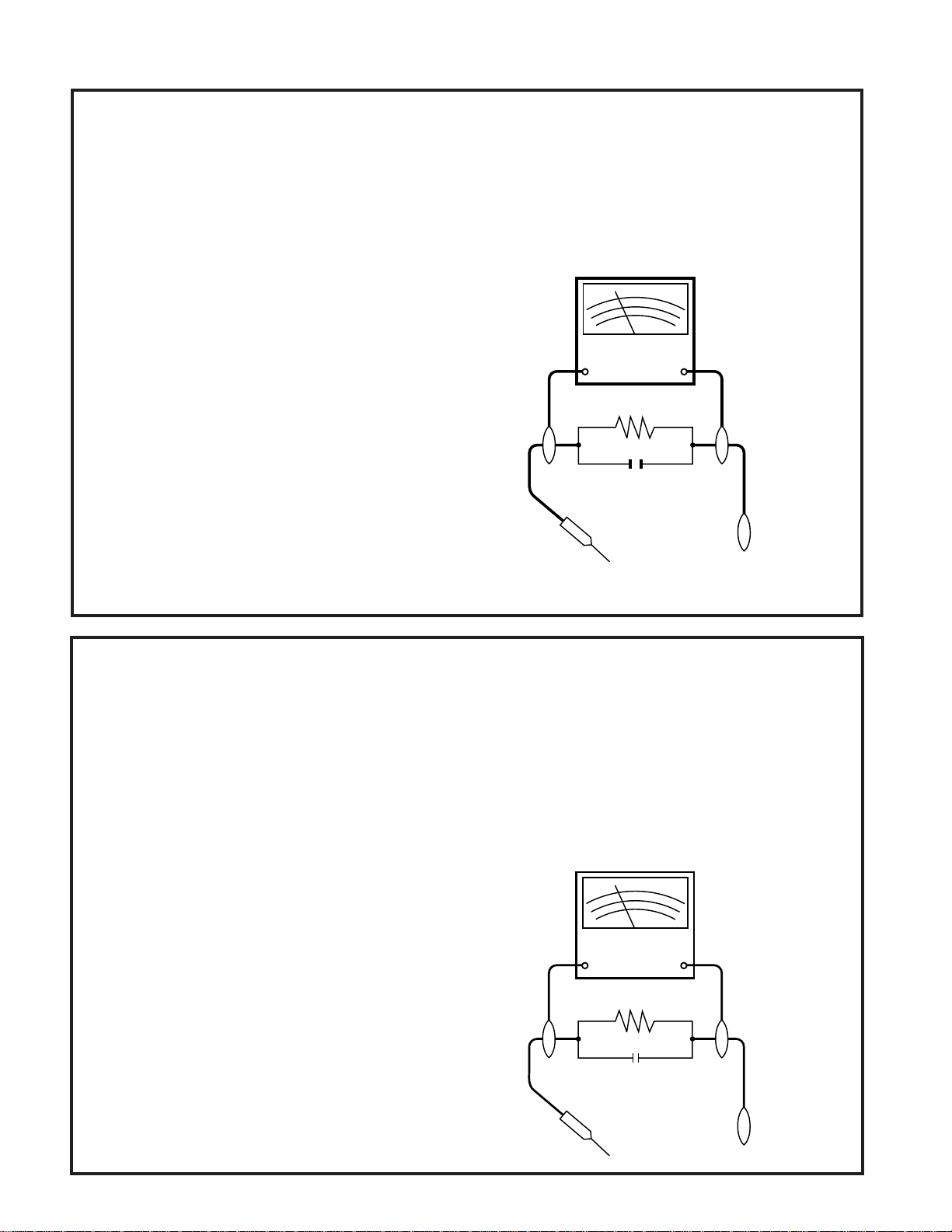
3. To be sure that no shock hazard exists, check for
current in the following manner.
● Plug the AC line cord directly into a 120 volt AC outlet
(Do not use an isolation transformer for this test).
● Using two clip leads, connect a 1.5k ohm, 10 watt
resistor paralleled by a 0.15µF capacitor in series with
all exposed metal cabinet parts and a known earth
ground, such as a water pipe or conduit.
● Use an DVM or VOM with 1000 ohm per volt, or higher,
sensitivity or measure the AC voltage drop across the
resistor (See Diagram).
● Move the resistor connection to earth exposed metal
part having a return path to the chassis (metal cabinet,
screw heads, knobs and control shafts, etc.) and
measure the AC voltage drop across the resistor.
Reverse the AC plug on the set and repeat AC voltage
measurements for each exposed part. Any reading of
0.45V rms (this corresponds to 0.3mA rms AC.) or
more is excessive and indicates a potential shock
hazard which must be corrected before returning the
DVD video player to the owner.
SSVM
AC SCALE
1.5k ohms.
10W
0.15 µF
TEST PROBE
TO EXPOSED
METAL PARTS
CONNECT TO
KNOWN EARTH
GROUND
1. NOTES DE SERVICE IMPORTANTES
AVANT DE RENDRE LE REPRODUCTOR DE VíDEO
DVD
Avant de rendre le reproductor de vídeo DVD à l’utilisateur,
effectuer les vérifications de sécurité suivantes.
1. Vérifier toutes les gaines de fil pour être sûr que les fils
ne sont pas pincés ou que le matériel n’est pas coincé
entre le châssis et les autres pièces métalliques dans le
reproductor de vídeo DVD.
2. Vérifier tous les dispositifs de protection tels que les
boutons de commande non métalliques, les matériaux
d’isolement, le dos du coffret, les couvercles de
compartiment et ajustement ou les boucliers, les
réseaux de résistance / condensateur d’isolement, Ies
isolateurs mécaniques, etc.
3. Pour être sûr qu’il n’y a aucun risque de choc électrique,
vérifier le courant de fuite de la maniére suivante.
● Brancher le cordon d’alimentation secteur directement
dans une prise de courant de 120 volts. (Ne pas utiliser
de transformateur d’isolement pour cet essai).
● Utiliser deux fils à pinces et connecter une résistance
de 10 watts 1,5 kohm en parallèle avec un condensateur
de 0,15 µF en série avec des pièces du coffret métallique
exposées et une masse de terre connue telle qu’un
tuyau ou un conduit d’eau.
● Utiliser un DVM ou VOM avec une sensibilité de 1000
ohms par volt ou plus ou mesurer la chute de tension
CA entre la résistance (voir diagramme).
● Déposer la connexion de la résistance à toutes les
pièces métalliques exposées ayant un parcours de
retour au châssis (coffret métallique, tétes de vis, boutons et arbres de commande, etc.) et mesurer la chute
de tension CA entre la résistance. Inverser la fiche CA
(une fiche intermédiaire non polarisée doit être utilisée
à seule fin de faire ces vérifications.) sur l’appareil et
répéter les mesures de tension CA pour chaque piéce
métallique exposée. Toute lecture de 0,45 V rms (ceci
correspond à 0,3 mA rms CA) ou plus est excessive et
signale un danger de choc qui doit être corrigé avant de
rendre le reproductor de vídeo DVD à son utilisateur.
VTVM
AC SCALE
1.5k ohms
10W
0.15 µF
TEST PROBE
TO EXPOSED
METAL PARTS
CONNECT TO
KNOWN EARTH
GROUND
2
Page 3
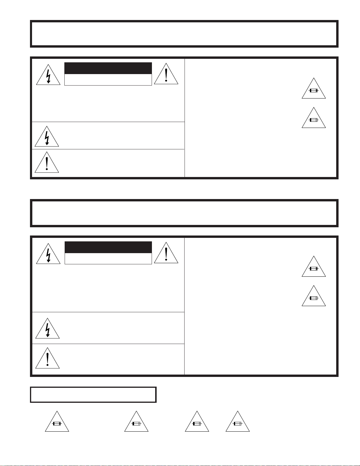
WARNING :TO REDUCE THE RISK OF FIRE OR ELECTRIC SHOCK, DO NO T EXPOSE
THIS APPLIANCE TO WET LOCATIONS.
CAUTION
RISK OF ELECTRIC SHOCK
DO NOT OPEN
CAUTION: TO REDUCE THE RISK OF ELECTRIC
SHOCK. DO NOT REMOVE COVER. NO
USER·SERVICEABLE PARTS INSIDE.
REFER SERVICING TO QUALIFIED SERVICE
PERSONNEL.
This symbol warns the user of uninsulated
voltage within the unit that can cause dangerous electric shocks.
This symbol alerts the user that there are
important operating and maintenance instructions in the literature accompanying this unit.
CAUTION
This symbol mark means following.
For continued protection against fire hazard, replace only with same type fuse
F901 (4A, 63V)/F902 (4A, 63V) on Power
PWB.
F9901 (1.75A, 32V) on CCFT INV. PWB.
CP9001 (1.6A, 72V)/CP9002 (2A, 72V)
on Power PWB.
1.5A 250V
DV-L88U
ATTENTION:POUR REDUIRE LES RESQUES D'INCENDIE OU DE CHOC ELECTRIQUE,
NE PAS EXPOSER CET APPAREIL A LA PLUIE OU A L'HUMIDITE.
ATTENTION
RISQUE DE CHOC ELECTRIQUE
NE PAS OUVRIR
ATTENTION: AFIN DE REDUIRE LES RISQUES DE
CHOC ELECTRIQUE, NE PAS RETIRER LE
COUVERCLE, AUCUN ORGANE INTERNE
NE PEUT ETRE REPARE PAR
L'UTIUSATEUR, CONFIER L'APPAREIL A
UN DEPANNEUR QUALIFIE.
Ce symbole signale à l'utilisateur la présence
d'une tension non isolée à l'intérieur de l'appareil
qui peut être la cause de secousses électriques
dangereuses.
Ce symbole avertit l'utilisateur que des instructions importantes relatives à l'utilisation
et àl'entretien se trouvent dans le manuel
accompagnant l'appareil.
ATTENTION
Ce symbole signifie que l'on devra utiliser un fusible de même type F901 (4A,
63V)/F902 (4A, 63V) on Power PWB .
F9901 (1.75A, 32V) on CCFT INV. PWB.
CP9001(1.6A, 72V)/ CP9002 (2A, 72V)
on Power PWB.
1.5A 250V
Fuse Replacement Marking
4A 63V
On Power PWB Inside of Enclosure LCD front
1.75A 32V
1.6A 72V 2A 72V
On Power PWB
3
Page 4

DV-L88U
åå
åCAUTION
åå
BEFORE BATTERY DESTROY
The RBRCTM Seal
SHARP participates in the RBRCTM* Nickel-Cadmium Battery Recycling Program in the United States. The RBRCTM
Seal on our battery pack contained in our product indicates that SHARP is voluntarily participating in an industry
program to collect and recycle these batteries. The RBRCTM program provides you with a convenient alternative
to placing spent Nickel-Cadmium battery packs into the trash or municipal waste stream, which is illegal in some
areas. At the end of their useful life, the Nickel-Cadmium battery can be dropped off at the nearest collection center
for recycling. For information on the nearest collection center, call 1-800-8-BATTERY or your local recycling
center. If you are located outside the United States, contact your local authorities for information concerning proper
disposal and/or recycling of this battery. SHARP's involvement in this program is part of our commitent to protecting
our environment and conserving natural resources.
[Footnote] *RBRC
TM is a trademark of the Rechargeable Battery Recycling Corporation.
ËË
Ë NICKEL-METAL HYDRIDE BATTERY
ËË
ËË
Ë LITHIUM or LITHIUM-ION BATTERY
ËË
ËË
Ë SEALED LEAD BATTERY
ËË
Battery disposal
Contains the above Rechargeable Battery. must be recycled or disposed of properly.
Remove the Battery from the products and contact Federal or State Environmental Agencies for information on
recycling and disposal options.
4
Page 5

2. FEATURES
This DVD video player can play back DVD video discs and Audio CDs.
• CD-R/CD-RW recorded in MP3 file format can also be played.
8" LCD Screen and Stereo Speakers
• A big 8" LCD screen and built-in stereo speakers provide exciting DVD viewing, even without connecting to a TV.
2-WAY Power Supply
• A 2-way power supply allows operation using the supplied AC adapter for indoor play, or the battery pack (supplied)
for outdoor play.
Compact, Lightweight Design
• Your DVD video player is designed to go along just about anywhere.
High-Resolution Images, High-Quality Sound
• A high-resolution 336,960-pixel LCD screen produces images of outstanding quality.
• DIGITAL GAMMA correction and DIGITAL SUPER PICTURE provide more realistic image detail.
• VIRTUAL DOLBY (*1QSURROUND) ensures richer sound from two built-in speakers.
AV input/output, optical digital output jack equipped as standard
• An optical digital output jack (which doubles as the phones jack) can be used to output a stream of *2Dolby Digital 5.1
channel audio and *3DTS digital audio. Connecting a Dolby Digital/DTS digital surround processor or amplifier to this
jack creates an environment of amazingly powerful surround sound.
• The AV input/output jack can be used to connect a VCR or camcorder to your DVD video player. Or you can use these
jacks to connect to a TV for big-screen viewing.
DV-L88U
*1QSURROUNDTM is a trademark of QSound Labs, Inc.
*2Manufactured under license from Dolby Laboratories. "Dolby", "Pro Logic" and the double-D symbol ( ) are
trademarks of Dolby Laboratories.
*3"DTS" and "DTS Digital Surround" are trademarks of Digital Theater Systems, Inc.
3. SPECIFICATIONS
Product: Portable DVD Video Player
Model: DV-L88U
Signal System: NTSC
Supported Disc Types: DVD (Region Number 1, ALL), Audio CD, CD-R, CD-RW
Video Input/Output: Input/Output Jack: Pin jack × 1
Input/Output Levels: 1Vp-p (75Ω)
S-Video Input/Output: Y Input/Output Level: 1Vp-p (75Ω)
C Input/Output Level: 0.286Vp-p (75Ω)
Input/Output Jack: S connector × 1
Audio Input/Output: Input /Output Jack: Pin jack × 1
Input/Output Levels: 1.7Vrms (1kHz, 0dB)
Digital Audio Interface: Optical Digital Output: Mini jack (shared with Headphones Output)
Audio Output: 0.8W + 0.8W
Headphones Output: Output Jack: Mini jack (stereo) (shared with Optical Digital Output)
Display: Screen Size: 8 inches (99.2 (357/64") (H) × 176.4 (615/16") (W) mm)
Type: Transmissive TN liquid crystal panel
Drive: TFT (thin transistor) active matrix
Pixels: 336,960 (234 (H) × 480 (W) × 3),
Effective Pixel Rate: 99.99% minimum
Speakers: Two 28mm round speakers
Light Source: Internal (fluorescent)
Video Signal: Horizontal Resolution: 500 lines
S/N Ratio: 60 dB
5
Page 6

DV-L88U
AC Adapter Specifications
Audio Signals: Frequency Characteristics:
Linear PCM DVD: 4Hz to 22kHz (48kHz sampling)/
4Hz to 44kHz (96kHz sampling)
CD: 4Hz to 20kHz (EIAJ)
S/N Ratio: CD: 96dB 1kHz (EIAJ)
Dynamic Range: Linear PCM DVD: 96dB (EIAJ)
CD: 96dB (EIAJ)
Total Harmonic Distortion Ratio: 0.006% maximum (EIAJ)
Power Requirements: AC Adapter: 10V DC
Battery Pack: 7.4V DC
Power Consumption: Main Power On: 12W average (10W without AC Adapter)
(AC Adapter) Main Power Off: 0.6W (standby) (0.1W without AC Adapter)
Dimensions: 211 (W) × 174 (D) × 42.3 (H) mm (85/16" × 655/64" × 143/64")
(except for projections)
Weight (approx.): 930g (2.05 lbs)
Operating Temperature: 5°C to 35°C (41°F to 95°F)
Operating Humidity: 80% RH maximum
Storage Temperature: -20°C to 40°C (-4°F to 104°F)
Power Requirements: 110 to 240V AC, 50/60Hz
Rated Output: DVD Operation: 10V DC
Charging: 10V DC
Dimensions: 54 (W) × 98 (D) × 26.5 (H) mm
(21/8" × 355/64" × 13/64")
Weight (approx.): 170g (0.38 lbs)
Battery Pack Specifications
Model: BT-L300U
Type: Lithium-ion type
DC output: 7.4V
Capacity: 5100mAh
Operating temperature: 0°C to 40°C (32°F to 104°F) (charging: 10°C to 30°C (50°F to 86°F))
Max. Dimensions: 59 (W) × 142.5 (D) × 20.5 (H) mm
(221/64" × 55/8" × 13/16") without protruding parts
Weight (approx.): 285g (0.63 lbs)
Specifications are subject to change without notice.
Weight and dimensions are approximate.
Digital Output (Linear PCM)
· The digital output format used in this DVD video player is Linear PCM audio sampled at 44.1kHz or 48kHz.
Linear PCM sound for DVD discs sampled at 96kHz cannot be output digitally.
Check the disc jacket for information on the audio sampling used.
3-1. ACCESSORIES
Accessories: AC Cord x 1, CR2025 type lithium battery x 1, Remote Control Unit x 1, AC Adapter x 1,
Lithium-ion Battery Pack x 1
6
Page 7
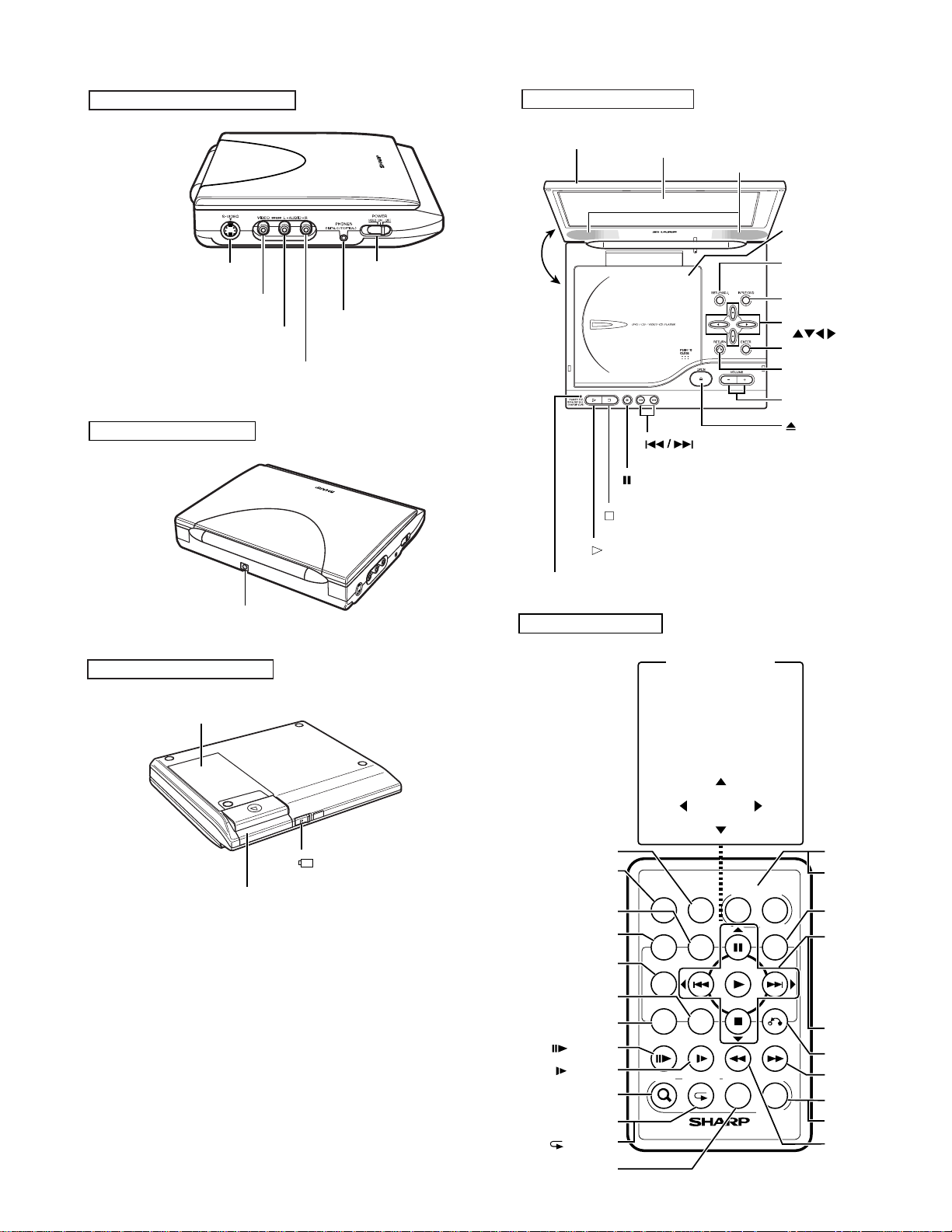
4. PART NAMES
DV-L88U
DVD Video Player - Right side
S-VIDEO
input/output jack
VIDEO
input/output jack (yellow)
AUDIO (L)
input/output jack (white)
AUDIO (R)
input/output jack (red)
DVD Video Player - Rear
POWER switch
DIGITAL OUT (OPTICAL)/
PHONES jack
DVD Video Player - Front
Display panel
angle range: 0°-180°
180°
0°
(SKIP)
(STILL/PAUSE)
(STOP)
(PLA Y)
LCD screen
Speakers
Disc compartment
cover
SETUP/ADJ.
INPUT/DVD
Cursor buttons
( )
ENTER
RETURN
VOLUME –/
+
OPEN
DC IN jack
DVD Video Player - Bottom
Battery pack compartment (inside)
Battery pack compartment cover
.
“ RELEASE” tab
Indicator lamp
Remote Control Unit
INPUT/DVD
POWER
FUNCTION
TITLE
MENU
VIDEO ADJ.
SETUP
(F.ADV)
(SLOW)
ZOOM
PROGRAM
(REPEAT)
DISPLAY
Select/Enter Mode
• The operation buttons
have the following
Select/Enter functions
when Setup screen,
Function control screen or
another type of setting
screen is on the display.
ENTER
INPUT
–
/DVD
POWER
FUNCTION
TITLE
MENU
SETUP
VIDEO ADJ.
PROGRAM DISPLAY VIEW MODE
ZOOM
DVD VIDEO PLAYER
VOLUME
ENTER
+
SHIFT
RETURN
LCD ON/OFF
–
VOLUME
VOLUME
+
SHIFT
â (STILL/
PAUSE)
à (SKIP)
û (PLAY)
Ë (STOP)
À (SKIP)
RETURN
è (FWD)
VIEW MODE
LCD ON/OFF
È (REV)
7
Page 8
DV-L88U
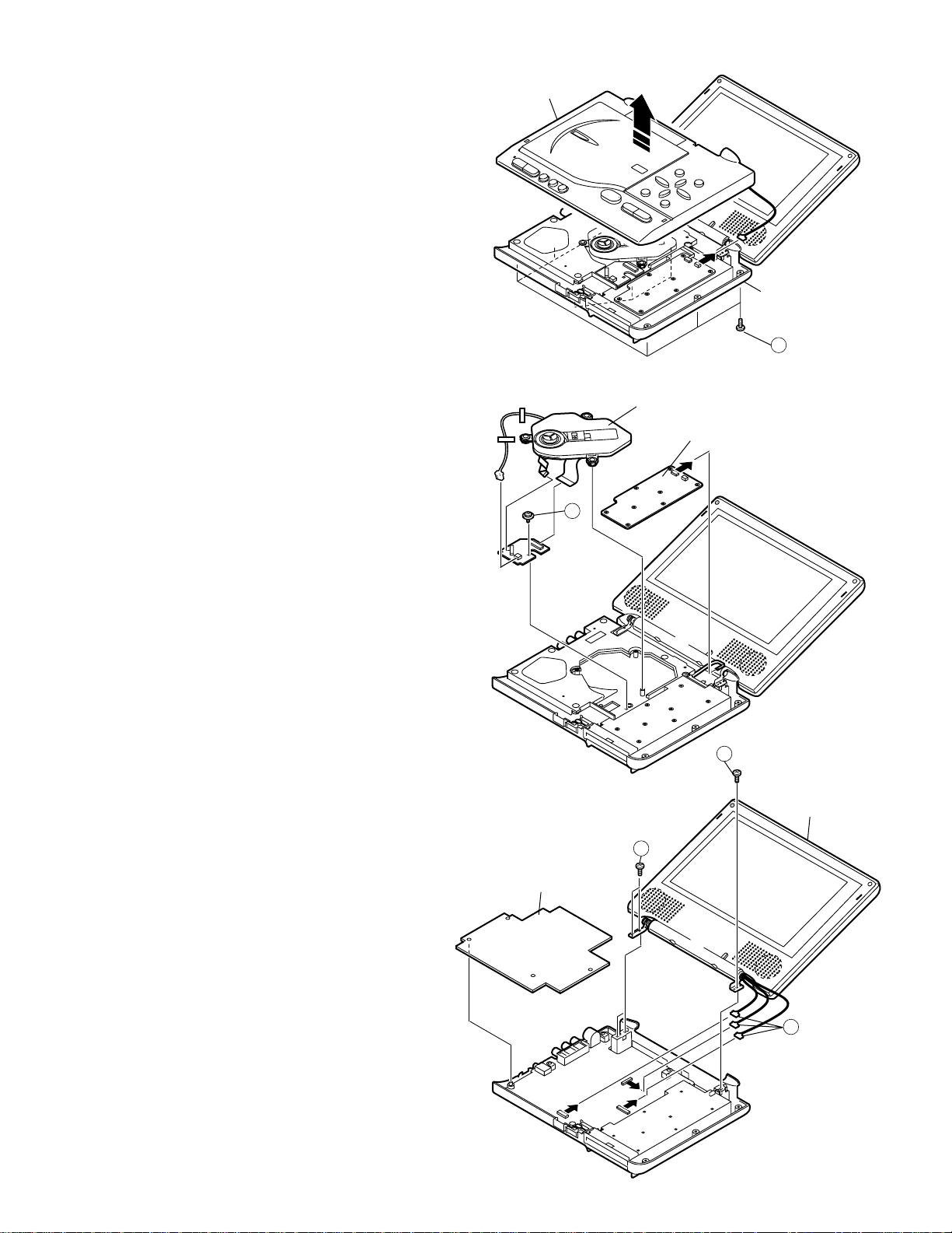
5. DISASSEMBLY METHOD
5-1. DISASSEMBLY METHOD
1. Remove the nine screws 1.
2. Remove the six screws and remove the battery cover.
3. Six screws of the operate PWB fixed are removed from
the cabinet B bottom.
4. Lift the cabinet A, remove the connector.
Cabinet A
Cabinet B
1
5. Remove the mechanism ass'y and operate PWB.
6. Remove the one screw 2.
7. Remove the three connectors 3.
8. Remove the three screws 4.
9. Remove the LCD unit.
10. Remover the main PWB.
Mechanism Ass'y
Operate PWB
2
4
LCD Unit
4
Main PWB
3
8
Page 9
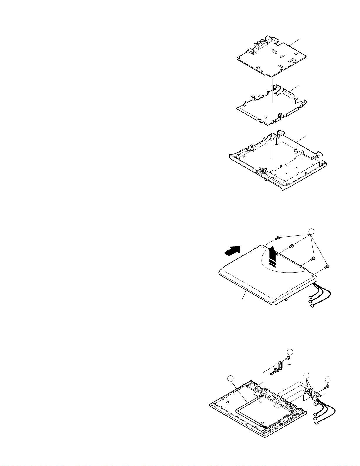
11. Remove the shield plate and power PWB from cabinet B.
Power PWB
Shield Plate
Cabinet B
Hinge L
Hinge R
7
8
7
6
12. Remove the power PWB and shield plate.
(Partly fixed with solder.)
DV-L88U
13. Remove the four screws 5.
14. Cabinet C is slided in the direction of ¤, and lifted in the arrow
direction of ⁄, and removed.
15. Remove the connectors 6 from the LCD PWB.
16. Remove the FFC 8 from the connector.
17. Remove the three screws 7, and remove the hinge L, R.
5
¤
⁄
Cabinet C
9
Page 10
DV-L88U
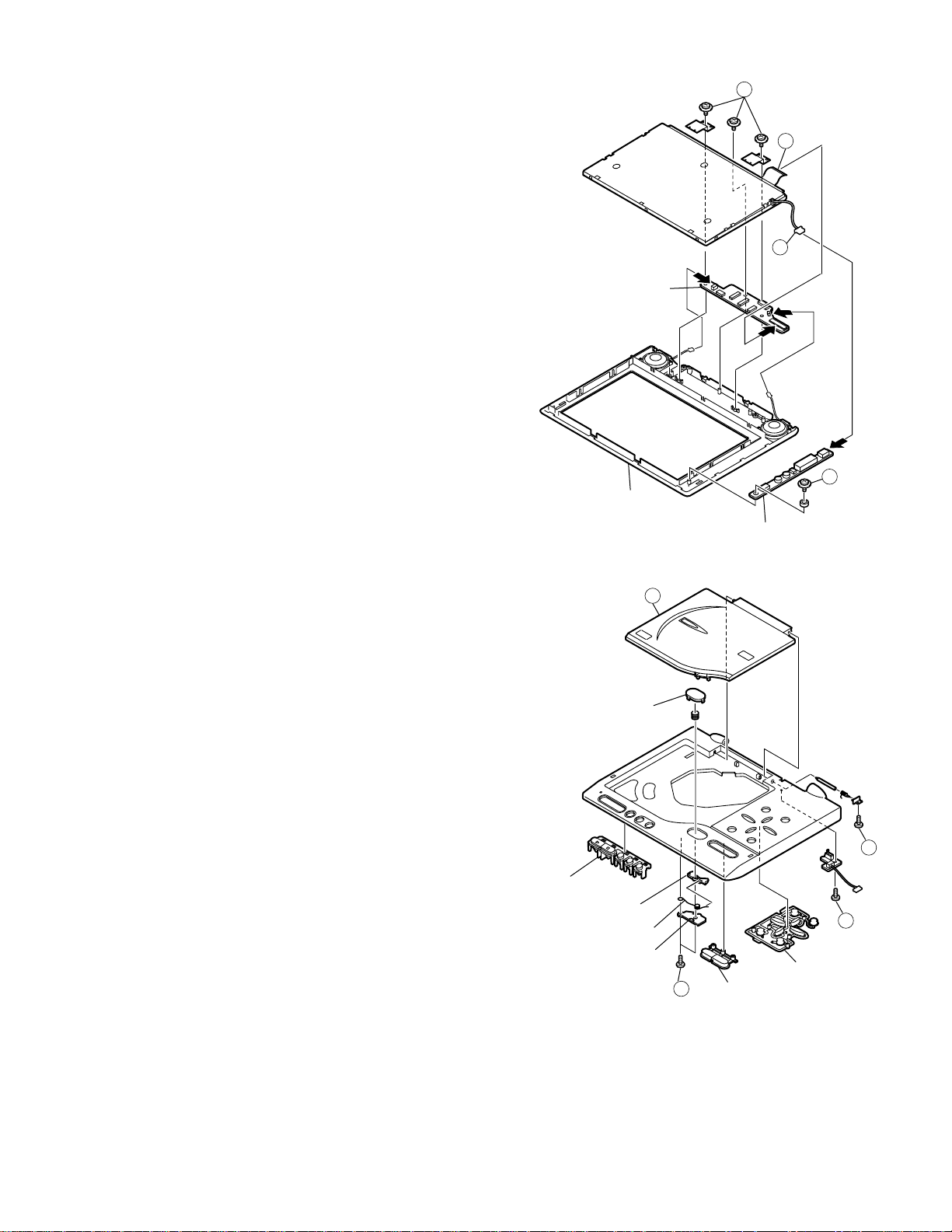
18. Remove the connectors 9 and 0.
19. Remove the three screws q, and remove the LCD fixing angle.
20. Remove the LCD from the cabinet D.
21. Remover the LCD CTL PWB.
22. Remove the screw w.
23. Remove the inverter unit.
11
9
10
LCD CTL PWB
12
Cabinet D
Inverter Unit
24. Remove the disc cover e by pressing open button.
25. Remove the one screw r.
26. Remove the one screw t.
27. Remove the two screws y.
28. Remover the lock holder, button lock spring and D. cover lock.
29. Remove the mode key, volume key, cursor buttons and open button.
Mode Key
Button Lock Spring
Open Button
D. Cover Lock
Lock Holder
13
16
Volume Key
14
15
Cursor Buttons
10
Page 11
DV-L88U
6. ADJUSTMENT METHOD
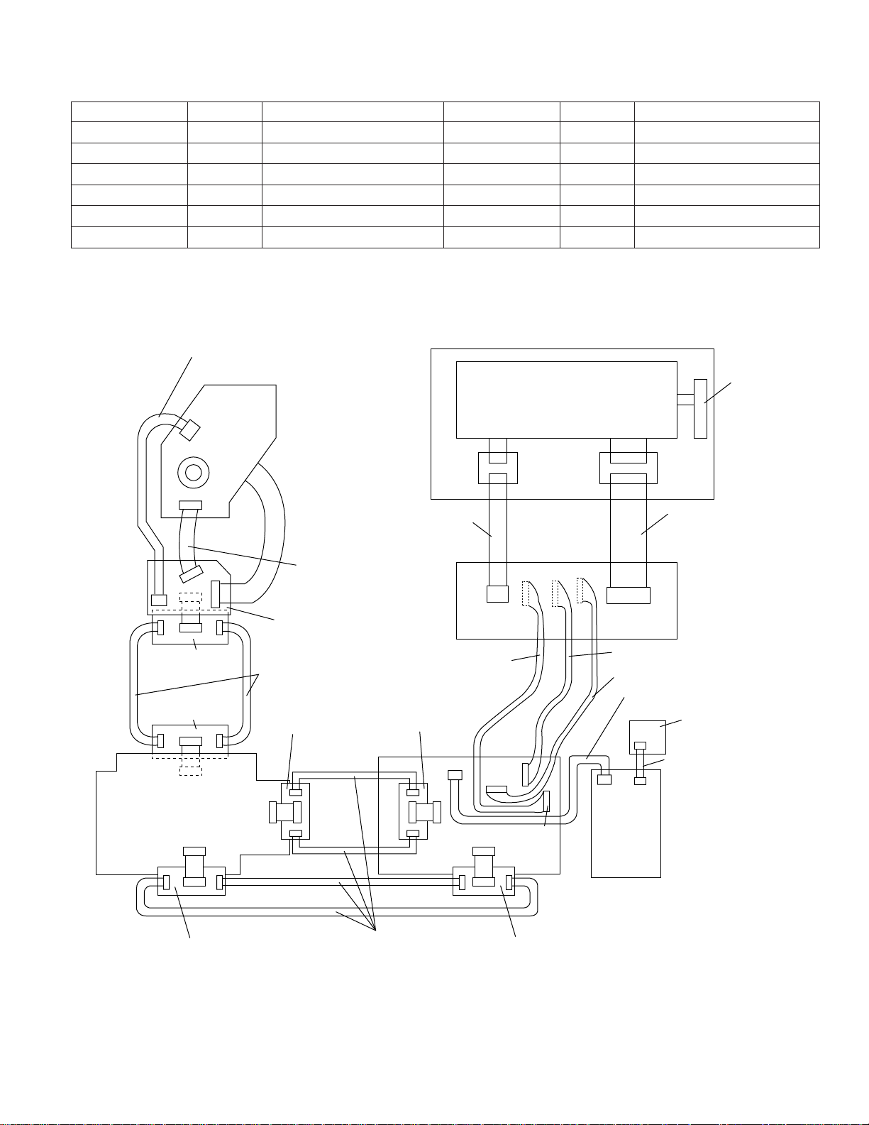
6-1. HARNESS LIST FOR SERVICE PARTS
Parts Code Price Code Remarks Parts Code Price Code Remarks
QCNW-8557GEZZ AE Spindle extension, 13-pin QCNW-8566GEZZ AD Operate PWB extension, 2-pin
QCNW-8558GEZZ AE Sled extension, 2-pin QCNW-8623GEZZ AZ
QCNW-8562GEZZ AK Power-LCD extension, 9-pin QCNW-8624GEZZ AX Main-Power extension, 15-pin
QCNW-8563GEZZ AK Power-LCD extension, 10-pin
QCNW-8564GEZZ AK Power-LCD extension, 12-pin
QCNW-8565GEZZ AE Operate PWB extension, 6-pin
99GFCKWB90751A BX —————
QCNW-8151GEZZ
QCNW-8152GEZZ
AQ Inverter extension, 6-pin
AQ LCD panel extension, 32-pin
Drawing for service jigs
QCNW-8558GEZZ
Mechanism
Panel
Main-RF&Motor extension, 25-pin
Inverter PWB
99GFCKWB90751A
99GFCKWB90751A
CN301
MAIN PWB
CN801
B
to
CN85
B
CN84
QCNW-8557GEZZ
RF&MOTOR
PWB
QCNW-8623GEZZ x2
99GFCKWB90751A
B
to
CN802
B
QCNW-8151GEZZ
QCNW-8562GEZZ
99GFCKWB90751A
CN5001
CN9901
CN82CN86
CN1901
CN1800
CN1802
CN6601
B
to
B
CN81
F
F
C
CN1903
12
10
POWER
CN83
9
CN1801
PWB
CN1902
12
9
CN1904
10
CN1900
QCNW-8564GEZZ
OPERATE
PWB
F
QCNW-8152GEZZ
F
C
LCD CTL PWB
QCNW-8563GEZZ
QCNW-8565GEZZ
DET LCD
CLOSE PWB
QCNW-8566GEZZ
CN4402CN4401
99GFCKWB90751A
QCNW-8624GEZZ x4
11
99GFCKWB90751A
Page 12
DV-L88U
ADJUSTMENT PROCEDURE AND METHOD OF LCD PWB SIDE
Connect it by using the jig and so on that a LCD PWB is packaged in the set or with the body.
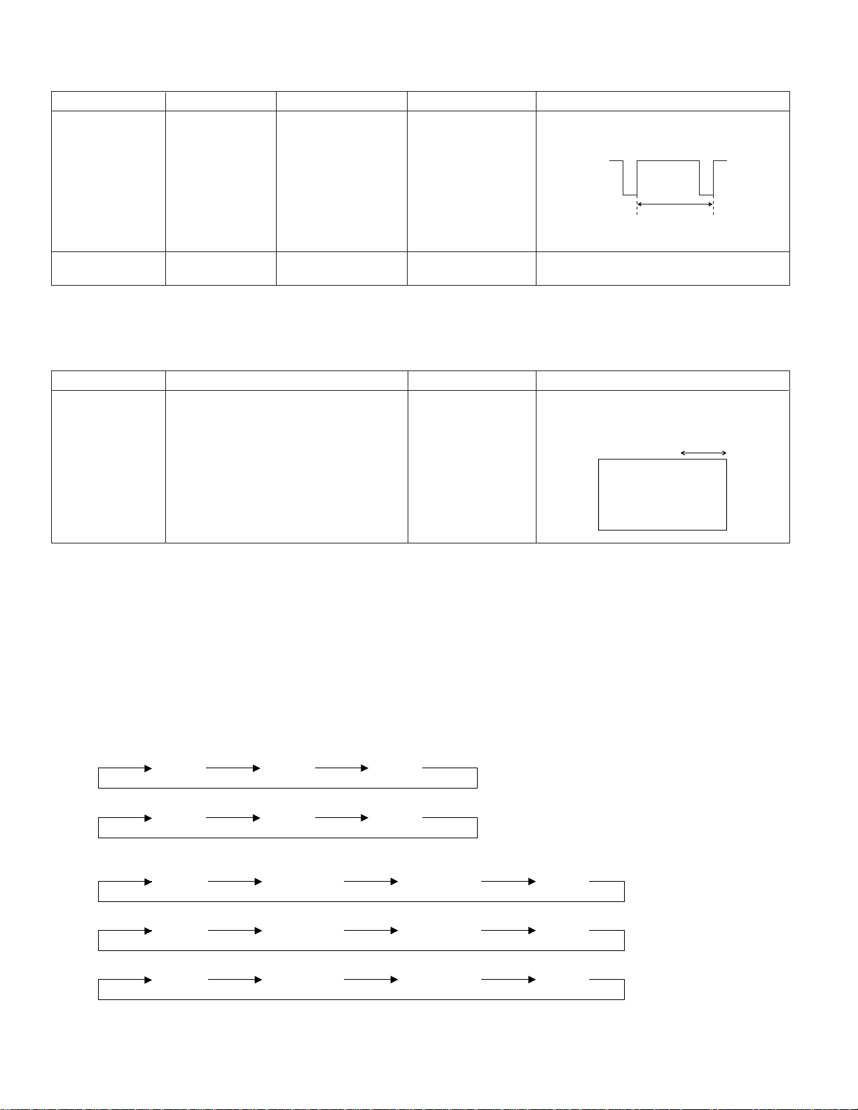
Adjustment Item Adjustment Menu Adjustment Point Signal/Setting Adjustment Contents
1Free run R1933 Observe the 5PIN of No input Adjust so that the frequency becomes
adjustment (VR) TP1900 (HSY) with a 15.73±0.1kHz (63.6µS).
frequency counter.
HSY
15.73kHz
(63.6µS)
2Screen center R1914(VR) Visual observation of Monoscope full Adjust the screen so that it is located in the
adjustment the panel. screen. (525/30) center.
[Caution] Do the image plane center adjustment of 2 after you surely do free run adjustment of 1.
Image plane center deviates when adjustment is done in the reverse order.
CHECK ITEMS OF LCD PWB SIDE
Adjustment Item Adjustment Point Input Signal/Setting Adjustment Contents
1Free run check Check the panel visually by connecting External input Check that the horizontal movement of OSD
to the checker. (525/30) is 2 mm or less when inputting a signal in
the external input mode with no signal input.
INPUT
POWER PWB SIDE ADJUSTING PROCEDURE AND METHOD.
Connect it by using the jig and so on that a POWER PWB is packaged in the set or with the body.
Supply the power in the condition that the “ENTER” and “STILL” keys are pressed at the same time and move to the special
mode (SP MODE).
After that, get the initialize set by pressing the “PLAY” key. After setting, turn off the power once.
Supply the power again in the condition that the “ENTER” and “STILL” keys are pressed at the same time and after moving
to the special mode (SP MODE), get the adjustment mode by pressing “INPUT/DVD” key.
Each operation in the adjustment mode changes as follows:
(1) Switch the adjustment block with the "VOLUME+" key input.
TV1
(2) Perform paging of each adjustment block with the "RETURN" key.
TV1
(3) Switch each adjustment item with the "VOLUME–" key input.
TV1 adjustment
GAM0
OPT
TV2
SBRIGHT GPOS CONT
BAT
TV3
TV2 adjustment
WB-R WB-B SCOLOR STINT
TV3 adjustment
COM OSDH BBRIGHT GAIN
(4) Change each adjustment value with the left or right cursor key.
12
Page 13
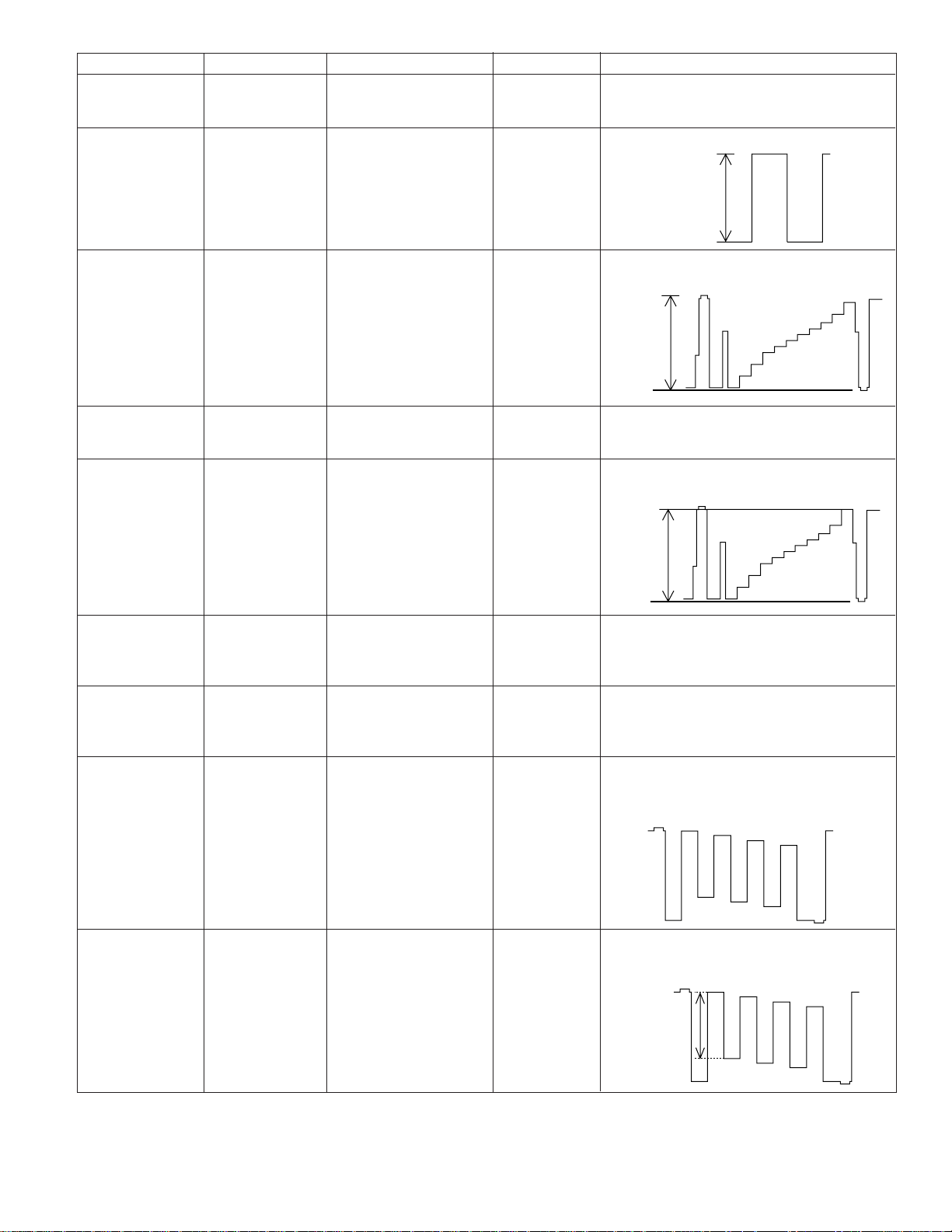
Adjustment Item Adjustment Menu Adjustment Point Signal/Setting Adjustment Contents
8.0V±0.1
Blue
Black
Red
Green
Yellow
Magenta
Cyan
White
1Sub-bright SBRIGHT Check that the SBRIGHT is “56”.
check
DV-L88U
2Common GPOS
amplitude
Connect the synchroscope
to 1 pin (COM) of TP1900.
Black-and-white Adjust the common amplitude to 8.0±0.1V.
10STEP
adjustment
3RGB amplitude GAIN
adjustment
Connect the synchroscope
to 2PIN (VG) of TP1900.
Black-and-white Adjust the Vpp(SYNC-SYNC) of VG to
10STEP 4.0±0.1V.
4.0V±0.1
4Gamma0 check GAM0 Check that the GAM0 is “50”.
5Contrast CONT
adjustment
Connect the synchroscope
to 2PIN (VG) of TP1900.
Black-and-white Adjust the 100% white part(SYNC-white100%)
10STEP to 3.8±0.1V.
3.8V±0.1
6White balance WB-R(Red)
adjustment
(Red)
7White balance WB-B(Blue)
adjustment
(Blue)
8Sub tint STINT
adjustment
9Sub color SCOLOR
adjustment
Connect the synchroscope
to 2PIN (VG) and 3PIN
(VR) of TP1900.
Connect the synchroscope
to 2PIN (VG) and 4PIN
(VB) of TP1900.
Connect the synchroscope
to 4PIN (VB) of TP1900.
Connect the synchroscope
to 4PIN (VB) of TP1900.
Black-and-white Adjust the white balance (red) so that black level
10STEP the equal of green and red output become equal.
Black-and-white Adjust the white balance (blue) so that black level
10STEP the equal of green and blue output become
equal.
100% color bar Make the peak to peak of the yellow, green
and red of the color bar signals stepwise or
same. Place green between yellow and red.
100% color bar Adjust the yellow amplitude of the color bar
signal (white level to yellow peak level) to
3.2±0.1Vpp.
White
3.2V
±0.1
Yellow
13
Page 14
DV-L88U
Direction of stripe
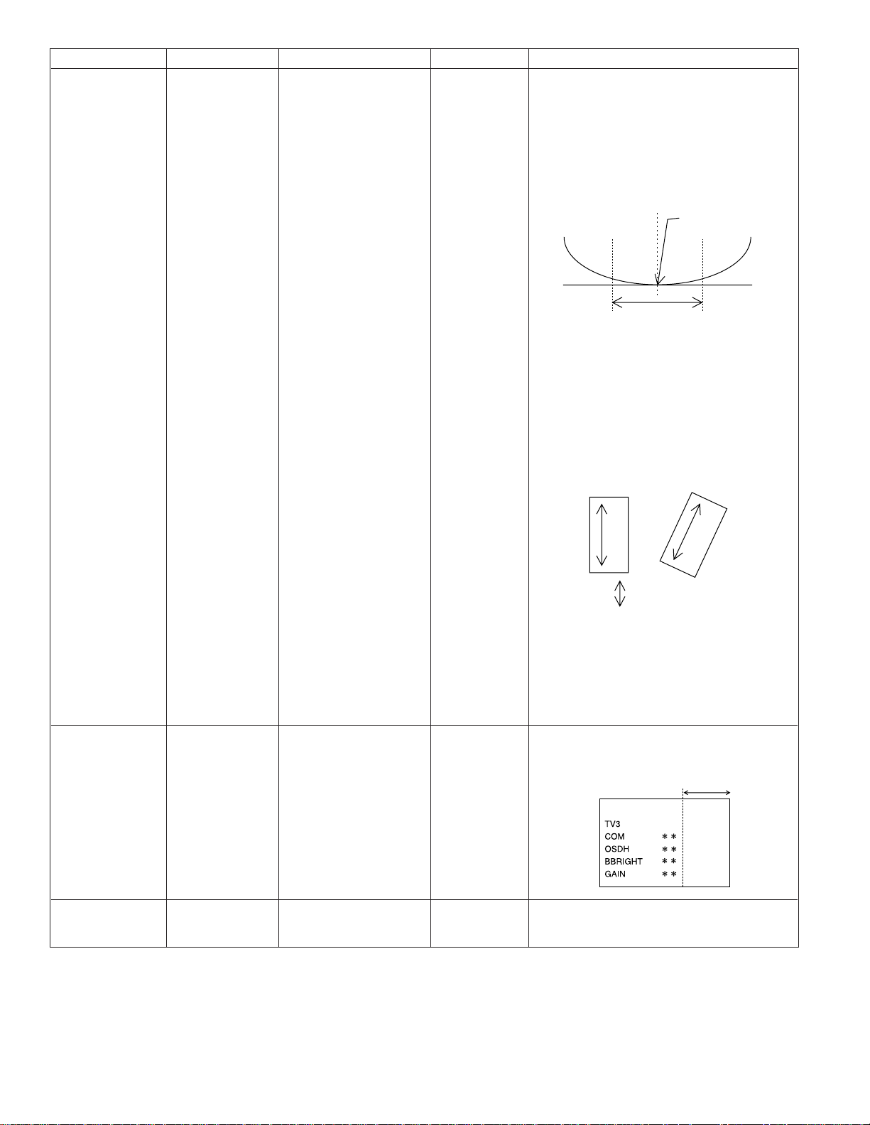
Adjustment Item Adjustment Menu Adjustment Point Signal/Setting Adjustment Contents
0Confrontation COM Specified adjustment jig No input state When using the specified adjustment jig
bias adjustment (illuminometer) or visual
observation Perform it in a and adjust the waveform to the minimum
Brightness: Center
combination of point.
PWB and the At this time, perform the adjustment several
liquid crystal times to fix the optimal point because the
panel which will measuring value hardly changes around the
be supplied as optimal point.
products finally.
Connect the output of jig to the oscilloscope
(Type drawing)
Adjust within the above
range to fix the optimal point
In case of visual adjustment Stand or tilt the
panel as shown in the figure and check by
shaking your head and seeing whether stripes
appear.
If the adjustment is improper, you will see
stripes in the longitudinal direction.
Perform the adjustment so that they
do not appear.
Optimal point
[Another method] [Another method]
Flicker signal Externally input the signal shown left and
generator adjust so that the cross bars become minimum
“Example: by visually checking the screen.
BP1018 made
by JFC”
qOSD position OSDH OSD character The position of the adjustment value on the
adjustment visual observation right end of the OSD character is adjusted to
15mm ± 2mm from the right end of the image
plane.
wLighting control BBRIGHT Check that the BBRIGHT is “76”.
standard check
15mm
14
Page 15
CHECK AND READJUSTMENT
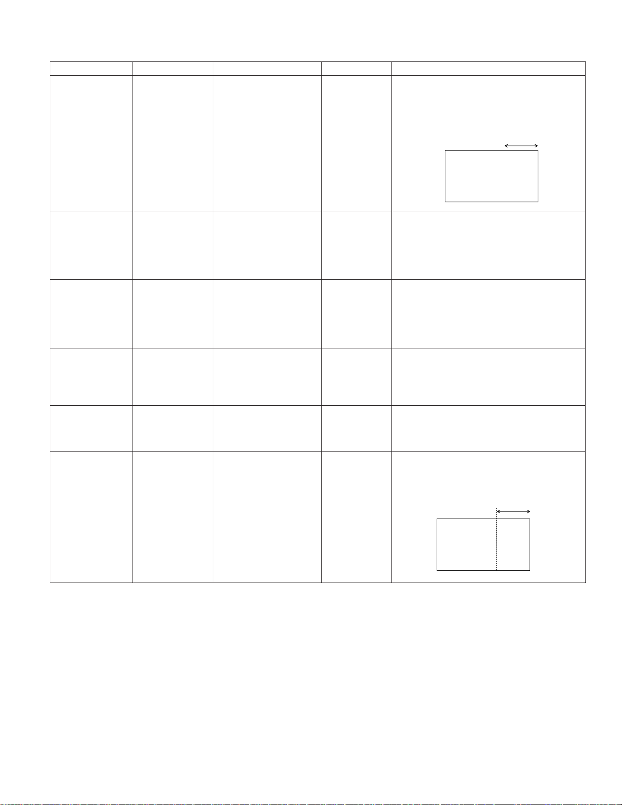
Adjustment Item Adjustment Menu Adjustment Point Signal/Setting Adjustment Contents
1Free run R1933 OSD character External input Check that the horizontal movement of OSD
check (VR) visual observation (525/30) position is 2mm or less when inputting a signal
in the external input mode with no signal input.
If it is more than 2 mm, adjust it so as to get
2 mm or less
INPUT
2Screen positon R1914 Visual observation of Monoscope full 95% of the scales for the overcoat scanning
check (VR) panel screen confirmation confirm whether it can be seen
(525/30) with the right and left as well in the monoscope
image plane. Center adjustment is done when
a scale can't be seen.
3Luminance/ GPOS Comparison with the 10STEP signal Check whether the luminance and gradation
gradation check standard set of 10STEP signal are not different in compar-
ison with the standard set. If they are different,
adjust them so as to get equal to the standard
set.
DV-L88U
4Sub color check SBRIGHT Comparison with the Check whether the depth of color is not diffe-
standard set rent in comparison with the standard set. If it is
different, addjust it so as to get equal to the
standard set.
5Sub tint check STINT Comparison with the Check wheter the tone is not different in co-
standard set mparison with the standard set. If it is different,
adjust it so as to get equal to the standard set.
6OSD positon OSDH OSD character External input Check the outside input mode, and it confirms
check visual observation that the character of INPUT of OSD is 15mm
± 2mm from the right end of the image plane.
When it deviates, it is confirmed.
15mm
INPUT
15
Page 16

DV-L88U
BATTERY END VOLTAGE ADJUSTMENT
1. Initial setting
(1) Power supply
Input 6.15V±0.05V to the DVD battery.
Note1) Set the voltage on the DC input jack PWB of the main unit to the value specified above in the condition of
DVD start-up (LCD lit).
Note 2) Check the voltage with a calibrated measuring instrument. In case that drift is worried, check the voltage
periodically.
2. Battery end voltage adjusting procedure and method
(1) Select the battery detection error compensation adjustment mode.
1 Turn on the main power switch on while pressing the “UP” “DOWN” keys of the main unit at the same time.
2 Press the mode selection key.
3 Press the sound volume down button twice to enter the battery adjusting screen.
4 With button changing button, make the cross key to the cursor mode. (With 70 type remote controller, the cursor
key can be used for operation as it is.)
(2) Adjust with the right and left key so that the “BAT” value displayed on the LCD becomes “0”.
No. Item Checked place Checking method Standard, condition Remarks
1 S image Y output S terminal 1. Play the test disc TDV - 581A.
2. Check the Y output with an 1Vp-p ± 0.15Vp-p S terminal Y output
oscilloscope. Measure at 75Ω
termination.
2 S image C output S terminal 1. Play the test disc TDV - 581A.
2. Check the C output with an 0.286Vp-p ± 0.15Vp-p S terminal C output
oscilloscope. Measure at 75Ω
termination.
3 Error rate check Display 1. Press the STOP key and the V-CD:TDV-581A When playing back.
PLAY key of the main unit key 20/4
at the same time and check
the error rate displayed on the
display.
DVD:TV-501
38/76
4 Flash memory Display 1. Press the return key and the Model name of the When NO DISC.
check VOL-UP key of the main unit software
key at the same time. Region code
Transmit the numeric number Software Ver.
key of R/C (1), next transmit
play to check the model name
and the region code, and
transmit play again to check
the software Ver.
Sound level check
5
Audio output
L/R
Play the title 49, chapter 1AC - 320
mode of the test disc TV - 501 to
check the sound output level.
1.35Vrms ± 0.3Vrms
6 Digital sound Digital sound Connect the digital surround The sound from the digital
output check output processor to the digital sound surround processor must
output and play the VCD to check be played properly.
the sound output from the digital
surround processor.
7 Distorted disc Played image Play the test disc TDV - 533 to It must be normally played.
playback check check the played image on the * No EJECT, rickety play
monitor screen. or staying in LOAD
condition are allowed.
16
Page 17

No. Item Checked place Checking method Standard, condition Remarks
8 Battery display Main unit LCD 1. Supply 8V to the battery
check terminal. Get the DVD start-up
screen.
2. Change the battery voltage to
7V. → Check the battery half
display.
3. Change the battery voltage to
6.5V. → Check the battery alarm
display.
4. Change the battery voltage to
5.9V. → Check the power is
turned off.
9 Charging action Main unit LED 1. Supply power from an
check AC adapter.
2. Connect 15Ω supplied a 6.5V
DC to the battery terminal → Check the LED for
or connect the empty battery. charging orange lights on.
DV-L88U
17
Page 18
DV-L88U
7. TEST MODE
Test Mode A power source is put, and a Skip/Forward key and a Volume Up key are pushed after the "NO DISC" display
ROM Renewal Mode A power source is put with pushing a Skip/Forward key and Volume Down key at the same time.
[TEST MODE]
Test mode initial image plane
F0000000 00000000
at the same time. (It keeps pushing it for about three seconds.)
(It keeps pushing it for about three seconds.)
<The "1" key of the remote controller is pushed.>
The preparation date display of the program
10000000 ********
(Last updata)
The "PLAY" key of the remote controller is pushed.
Model number display
10000001 00007604
(Model number)
The "PLAY" key of the remote controller is pushed.
The version display of the program
10000002 ********
(Program ver.)
The "PLAY" key of the remote controller is pushed.
Reagion number display
10000003 00000008
(Region code:Binary display)
The "PLAY" key of the remote controller is pushed.
Micro-code number display
10000004 ********
(Microcode ver.)
The "PLAY" key of the remote controller is pushed.
The preparation date display of the servo program
10000005 ********
(Servo ver.)
The "PLAY" key of the remote controller is pushed.
It is returned to the test mode initial image plane.
Micro-code is the thing of the process
program of the system integrated circuit.
<The "2" key of the remote controller is pushed.>
Color bar display
20000001 00000000 (FIP)
Color bar display
20000002 00000000 (FIP)
Color bar display
20000003 00000000 (FIP)
Color bar display
20000003 00000000 (FIP)
<The "3" key of the remote controller is pushed.>
To (1)
There is no copy guard signal.
What is the symptom at the time of dubbing to VTR?
The "PLAY" key of the remote controller is pushed.
AGC only
What is the symptom at the time of dubbing to VTR?
The "PLAY" key of the remote controller is pushed.
AGC+Color stripe1
What is the symptom at the time of dubbing to VTR?
The "PLAY" key of the remote controller is pushed.
AGC+Color stripe2
What is the symptom at the time of dubbing to VTR?
The "PLAY" key of the remote controller is pushed.
18
Page 19
From (1)
<The "1" key of the remote controller is pushed.>
<Disk is put, and the "2" key of the remote controller is pushed.>
*It is usually returned in power source off for the state.
STEP TEST
30000201 00000000
DVD laser lights, the spindle motor
rotates and the pickup moves to the
outer periphery.
30000001 000000DD
DVD laser off, CD laser on, spin kick,
sled outer periphery feed
ErrDisplay0 ErrDisplay1
30000001 000000CD
Laser off, spin kick, sled outer periphery
feed
ErrDisplay0 ErrDisplay1
30000001 00000000
Focus on
The "PLAY" key input.
<The "1" key of the remote controller is pushed.>
<The "1" key of the remote controller is pushed.>
<The "1" key of the remote controller is pushed.>
STEP TEST
DD00E210 EEEEEEEE
DV-L88U
Note:Not to face the light of the laser squarely,
caution!
When a disk is not in.
STEP TEST
30000202 00000000
STEP TEST
30000203 00000000
STEP TEST
30000204 00000000
STEP TEST
30000205 00000000
STEP TEST
DD000210 00000000
STEP TEST
DD000211 00000000
RF gain adjustment, Track on
The "PLAY" key input.
Focus gain adjustment
The "PLAY" key input.
Track gain adjustment
The "PLAY" key input.
Focus balance adjustment
The "PLAY" key input.
(In case of CD)
STEP TEST END
CD000210 ********
(******** is sub-Q.)
After TOC Reading,
Follow-up play condition
STEP TEST END
DD000212 ********
(******** is the sector ID.)
Focus balance of the layer 1,
follow-up play condition after focus gain adjustment
19
Page 20
DV-L88U
Personal computer
(DOS)
DVD itself
Connect to the video input
terminal.
Connect the “red” audio cable to jig.
Fixture for the ROM renewal
[ROM RENEWAL MODE]
1. Connect the DVD main unit and the computer as shown on the right. And then start-up the software for rewriting.
2. Turn on the power while the Skip/Forward key and the Volume Down key of the DVD main unit are kept pressed at the same time.
(Keep pressing about 3 second.)
The red LED flickers 5 - 6 times with the 0.5 second cycle and then the green LED flickers with 0.1 second cycle.
3. According to the computer display, data transfer prompt is issued by inputting “Y” and
pressing ENTER key, and when the rewriting starts normally,
The LED in green lights on from flickering.
4. When the rewriting is completed normally,
The green LED lights on.
5. After completing the rewriting and checking the display of No. 4 shown above,
always press the “RETURN” key. After that turn off the POWER.
6. Treatment in case of rewriting error
1 The red LED flickers with 0.1 second cycle (When the stop key is pressed it
return to the condition of “2” so write again.)
2 The red/green LED flickers by turns (When the stop key is pressed it becomes
the condition of “5” so write again from “1”.)
20
Page 21

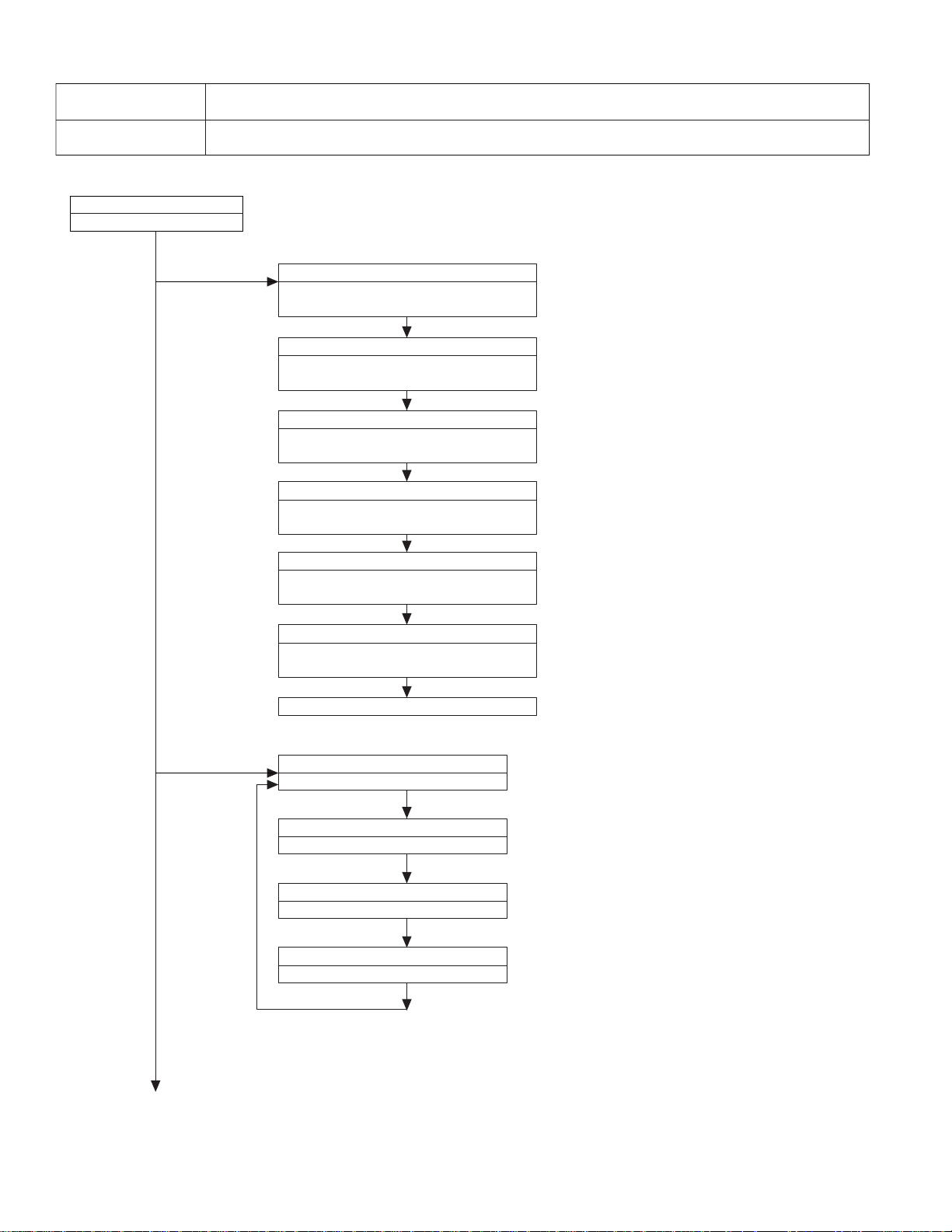
DV-L88U
Check AC adapter or battery-pack.
No
Voltage on DC JACK (Approx. 10V) or battery
terminal (8.4 - 6V)?
Yes
The power cannot be turned on.(1)
•When using the AC adapter ------check circuit
around F901, Q904, Q905.
•When using battery------check circuit around
F902, Q906, Q913.
No
Voltage specified above (Approx.6 - 10V) on
TP9002, TP9003?
Yes
Voltage of approx. 6 - 11V supplied on 4 pin of
IC5503?
No
Voltage of approx. 5V supplied on 72 pin of
IC5502 (TV microcomputer)?
Yes
Yes
29 pin of IC5502 still “L”?
No
Oscillation signal of 32kHz checked on 23, 24 pins
of IC5502?
Yes
Check the IC5502 and X5502.
Check the Q5503 and Q5504.
No
No
No
Yes
Circuit protector CP9001 is actuated (disconnection)
replace. Check LCD inverter circuit, INV-V line,
D5510, D5511, D5512, Q5506 and Q5507.
Refer to “The key operation is disabled.” or
“No operation is possible from the infrared remote
control.”.
No
•Approx. 5V outputted to 45 pin of IC5502?
•Approx. 5V outputted to 46 pin of IC5502?
(DVD mode)
No
Yes
Check PCON-H line between IC5502 - IC9001.
•Approx. 4.5 V supplied to 20 - 21 pins of IC9001?
•Approx. 4.5 V supplied to 22 pin of IC9001?
(DVD Mode)
Yes
Appropriate voltage outputted on each B line
(TP9005 - 9012)?
No
No
Yes
Triangle oscillation of approx. 0.6V p-p checked on
17 pin of IC9001?
Circuit protector CP9002 cut?
Yes
Check short circuit of each SWITCHING TR and
each B line.
* All the B lines cannot be outputted for short
circuit of even 1postion (1 line).
Replace IC5503.
Replace IC9001.
FLOW CHART NO.1
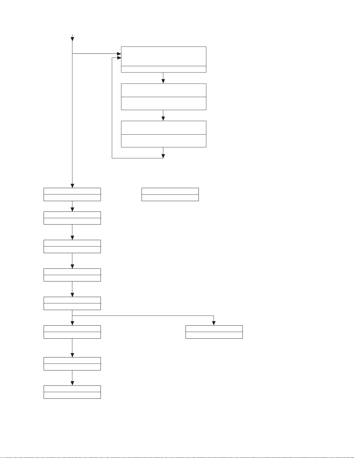
Attach junction line properly or replace junction line.
No
Wire between operation PWB and Power PWB
connected properly?
Yes
Yes
The key operation is disabled.
No
Slide switch does not function.
No
When slide switch is placed "ON", 5 pin of IC5502
is "L"?
Yes
Is the control voltage normally into the pins(78)
and (80) of IC5502? (78pin→KEY)
Replace S5501.
Yes
Replace operation pwb or S4001~S4005.
Replace IC5502.
No
Replace IC5502.
FLOW CHART NO.2
Check TVMI_5V line.
Replace the remote control receiver.
FLOW CHART NO.3
Operation is possible from the body, but no
operation is possible from the infrared remote
control.
Replace the remote control receiver or replace the
remote control transmitter is necessary.
Is 5V voltage supplied to the pin 2 terminal of
remote control receiver?
Is the "L" pulse sent out pin 3 terminal of receiver
when the infrared remote control is activated?
(Actuated with power button)
DVD cannot be operated but TV can be operated.
(DVD is actuated with play, stop button.)
To 2
1“L” pulse signal is generated from 79 pin of
IC5502?
(Actuated with power button)
No
No
No
Yes
No
To 1
Replace IC5502.
No
Yes
Check line of 2 pin of IC4001.
2“L” pulse signal is generated from 32 pin of
IC502?
(DVD is actuated with play, stop button.)
Replace IC502.
No
Yes
Check D512 line.
Yes
Yes
Yes
No operation is possible from the infrared remote control.
0.5
1
1.5
2
2.5
3
3.5
4
4.5
5
PLAY
STOP
STILL
SKIP/BACK
SKIP/FORWARD
DVD/INPUT
SETUP/ADJUPRIGHT
LEFT
DOWN
ENTER
RETURN
VOL-UP
VOL-DOWN
8. TR OUBLESHOOTING
21
Page 22

DV-L88U
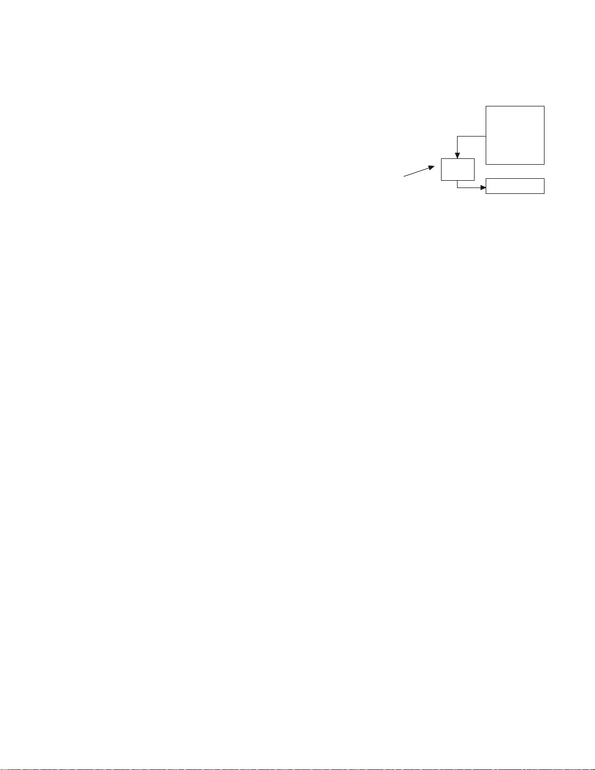
FLOW CHART NO.4
Is the tray lid open?
When S802 is pressed, are the pins 3 and 4
short-circuited?
Check the connection between pins 2 or 4 of S802
and pin 27 of IC502.
Does the pickup move in the direction of inner
periphery?
No
No
No
No
Check the cable connecting to the CN7302.
(Check the CN7302 and line of pins 2 and 4 of IC705.)
Check the cable connecting to the CN7303.
Replace the S802.
Yes
No
Yes
After moving in the direction of inner periphery,
does the pickup move in the direction of outer
periphery?
Yes
Check the M_4.8V line.
Is 4.8V being applied to the pins 16 and 17 of
IC7701?
Yes
Replace the IC7701.
Yes
The disc does not rotate.
No
Is FE signal inputted into the pin 150 of IC701.
Check or replace IC701.
Check the line between the IC301 and IC701.
FLOW CHART NO.5
When removing disc and applying load to spin
motor (by stopping with hand, etc.), objective lends
moves up and down? (Checking item to symptom)
Note) If load is not applied to spin, lens does not
move and becomes NO DISC immediately.
See FLOW CHART NO.6<The [No Disc] indication.
(In case focus servo does not function.)>
Replace IC301.
Is there input signal on the pins(50,55) and (49,54)
of IC301?
Is FE signal output to the pin 21 of IC301 when
the disc is set?
No
No
Check the connection of optical pickup cable.
If it is normal, replace the optical pickup.
Yes
No
Yes
Yes
Yes
The [No Disc] indication. (In case of focus error)
In case of CD For DVD, 58, 59, 63, and 64
FLOW CHART NO.6
Is the focus control signal output to the pin 14 of
IC701?
Check the IC701 DAC power source periphery
circuit. If it is normal, replace IC701.
Check M_5V line.
Is 8V voltage applied to the pins 8 and 27 and
25 and 24 of IC705?
Replace IC705.
Is the focus control signal from the pin 158 of
IC701 input into the pin 20 of IC705?
Check the focus control signal (DA0) line between
the IC705 and IC701.
Is the focus control drive voltage output from the
pins 29 and 30 of IC705?
No
No
No
Yes
Yes
Yes
No
Yes
The [No Disc] indication. (In case focus servo does not function.)
Check the line between the IC705 and the focus
actuator.
Focus control drive voltage applied to 27, 29 pin
of CN7301 (focus actuator terminal)?
Check the connection of optical pickup cable.
If it is normal, replace the optical pickup.
FLOW CHART NO.7
Check the D_3.1V line and A_5V line.
Is the drive signal (SEL) of Q301 (LD POWER
ON) being output to the pin 37 of IC701?
Is the drive signal (LDO1) of Q302 (LD POWER
CTL) being output to the pin 45 of IC301?
When S801 is pressed, is the base of Q303 0.8V?
Is the voltage of 3.3V being applied to the emitter
of Q301? And, is the voltage of 3.4V being applied
to the emitter of Q302?
Is the voltage of 3.1V and 2.3V being applied to
the pins 14 and 23 of CN7301, respectively?
Check the connection of optical pickup cable.
If it is normal, replace the pickup.
Check the Q301 and line between Q302 and
CN301.
Check the line from the pin 37 of IC701, through
Q305, to the base of Q301.
Check the line between the pin 45 of IC301 and
base of Q302.
Check the line between S801 and R323.
No
No
No
No
No
No
Yes
Yes
Yes
Yes
The DVD disc is not recognized.
(When the laser beam does not go on)
FLOW CHART NO.8
Check the A_5V line.
Is the drive signal (LDO2) of Q304 (LD POWER
CTL) being output to the pin 4 of IC301?
When S801 is pressed, is the base of Q304 0.8V?
Is the voltage of 3.4V being applied to the emitter
of Q303?
Is the voltage of 2.3V being applied to the pin 9
of CN7301?
Check the connection of optical pickup cable.
If it is normal, replace the pickup
Check the line between Q304 and CN7301.
Check the line between the pin 4 of IC301 and
base of Q303.
Check the line between S801 and R323.
No
No
No
No
Yes
Yes
Yes
The CD disc is not recognized.
(When the laser beam does not go on)
FLOW CHART NO.9
Check tray switch. S801, 802
No
Check for contamination of objective lens of
optical pickup.
Replace the optical pickup unit.
When cover is closed, disc starts rotating?
Check the main PWB unit.
Set disc to mechanism.
Replace the main PWB unit.
Is the level of RF signal which is output from
pin 28 of IC301, normal?
No
No
No
Yes
Yes
Yes
Yes
Both picture and sound do not operate normally.(1)
22
Page 23

DV-L88U
FLOW CHART NO.10
Check or replace Q2201.
Set the disc on the disc tray.
Check the V-MUTE line.(Pin3 of D2204)
5V applied to 1 pin of IC2201?
Are the video signals shown above input into
the pins of IC2201?
IC2201 2PIN Y/CR
IC2201 15PIN C/CB
Are the video signal outputted to each pins of
IC2201?
(1)When S1-OUT/VIDEO OUT is selected with the
signal selection switch(Q2201).
IC2201 11PIN CVBS
IC2201 6PIN S-Y
IC2201 12PIN S-C
Check the line between the pins of main unit
IC601 and the pins of IC2201.
IC601 105PIN → IC2201 2PIN Y/CR
IC601 106PIN → IC2201 15PIN C/CB
No
No
No
Yes
No
Yes
Yes
Picture do not operate normally.
FLOW CHART NO.11
Check or replace IC6801.
Set disc to DISC tray and play.
Digital sound signal inputted to each pin of
IC6801?
IC6801 5PIN AMCLK
IC6801 3PIN ABCLK
IC6801 1PIN ALRCLK
IC6801 2PIN AOUT0
Check each line between each pin of IC601 and
each input pin of IC6801.
IC601 131PIN → IC6801 5PIN AMCLK
IC601 141PIN → IC6801 3PIN ABCLK
IC601 139PIN → IC6801 1PIN ALRCLK
IC601 136PIN → IC6801 2PIN AOUT0
System control signal inputted to each pin of
IC6801?
IC6801 26PIN DAC DA
IC6801 27PIN DAC CK
IC6801 28PIN DAC L
IC6801 22PIN RSTO I
Check or replace IC6801.
Check each line between each pin of IC504 and
IC251 and each input pin of IC6801.
IC504 110PIN → IC6801 26PIN DAC DA
IC504 111PIN → IC6801 27PIN DAC CK
IC504 112PIN → IC6801 28PIN DAC L
IC251 77PIN → IC6801 22PIN RSTO I
No
No
Yes
Yes
Yes
Check or replace IC6610.
Yes
Yes
Sound is not given properly from speaker.
Control signal inputted to each in of IC6610?
IC6610 2PIN VOL_UP
IC6610 3PIN VOL_DOWN
Check from each pin of IC5502 to each input pin
of IC6610.
IC5502 33PIN → IC6610 2PIN VOL_UP
IC5502 4PIN → IC6610 3PIN VOL_DOWN
No
Yes
Is 15 pin of IC6610 low?
Check the Q6609, D6601, R6001, J6001.
No
Yes
Sound signal inputted to each pin of IC6610?
IC6610 5PIN Lch Input
IC6610 23PIN Rch Input
Check the IC6604, IC6605 and IC6607 and
peripheral circuit.
No
Yes
Charge troubleshooting
Go to item 4.
Charge LED (orange) lights on?1.
Yes
No
No
No
Yes
No
No
Yes
Yes
Yes
No
Power supplied from AC adapter?
Power of main unit can be turned on and off?
Power of main unit OFF?
F901 fuse is not cut?
Voltage of battery alone is 2V or more?
Replace fuse.
Failure of battery.
Cannot be charge.
Failure other than charging.
Cannot be charged when power is ON.
Turn off power and check.
Breakdown of IC5502.
44 pin of IC5502 is H?4.
No
No
No
No
Yes
Yes
Yes
2 pin of IC901 oscillating at approx. 200kHz?
19 pin of IC901 oscillating at approx. 200kHz?
Voltage on C901?
Yes
Yes
Investigate CHG_ON line.
Investigate from C901 to battery terminal.
Check around IC901 or breakdown of IC901.
Check around IC901 or breakdown of IC901.
Investigate Q908, D906, L901, and R915.
In the condition that power is supplied from AC adapter and power is off, nothing is connected to battery terminal.2.
Yes
No
Yes
No
Yes
No
Voltage of 0V/8.4V generated to battery terminal
cyclically.
"H" voltage on 8 pin of IC5502?
Yes
Investigate CHG_ON line. Charging circuit must
function accompanied by CHG_ON cyclically.
Voltage on 77 pin of IC5502?
44 pin of IC5502 repeating H/L cyclically?
If certain voltage is on, investigate BAT_V line.
When battery is not connected, voltage of 0V/4.2V
is outputted cyclically.
Study on other items.
Investigate line of DCIN_H.
Only battery is connected. (Assume herein that battery with voltage of 7.4 V is connected.)3.
Yes
No
No
No
Yes
Voltage of 3.7V on 77 pin of IC5502?
Voltage on 6 pin of Q905?
Yes
1V or less on 4 pin of D5509?
Investigate around Q905.
No problems with this item.
Investigate around IC5505.
Investigate around IC5505.
23
Page 24

DV-L88U DV-L88U
9. BLOCK DIAGRAMS
9-1. MAIN BLOCK DIAGRAM
J
I
H
G
F
E
D
C
B
A
1234567891011 12 13 14 15 16 17 18 19 20
24~25
Page 25

DV-L88U DV-L88U
9-2. MAIN/LCD BLOCK DIAGRAM
VSS (-16V)
Q6603
R1929
R1930
R1941
R2254
R6657
R6658
R6651
R6652
Q6609
15
23
12
13
(SP-MUTE)
VGH(+13V)
5
6
23
20
15
9
4
14
11
J2001
TPA0152
IC6610
23
4
9
21
16
Q6606Q6605
D_3V
Q6601
J6001
J2002
IC1806(1/2)
J
AT_A_5V
R1809
R1813
(GAMMA 0)
+
Q1838
Q1802
Y/VIDEO
AT_A_5V
R1816
Q1807
R1831
DVD_L
C1842 C1825
R1855
TH5501
R5529
LED-R, G
D5503
C5510
C5516
57
37
56
54
22
55
21
38
36
60 LED_R
61 LED_G
AT_A_5V
R1810R1805
R1807
Q1800
R1803
I
C1846
R1889
R1853
R1854
C1848
R1870
R1847
C1828
C1831
X1800
AT_A_5V
A_7.5V
R1899
D1803 1/2
H
Q1804
D1803 1/2
DVD_L
AT_A_5V
G
F
AT_A_5V
IC3201
MB8346BV
E
D
IC5501
C
B
A
_1
_1
_1
R/C
MICS
TV_KEY1
TV_KEY2
PCON_H
DVD_PCON
TU_PCON
LED_G
LED_R
HOLD
POWER
R1812
C1803
C1807
R1808
6867666970
_1
_1
19
2018164579
C1805
IC1802
IC1804
IR3Y29AM
D1800
62
_1
R1804
PCON_M
IC1801
MIRST
DVD_PCON
46
154759
C1809
S803
D5504
R1811
C1806
IC1800
SNT1G08C
AT_A_5V
Q1801
AT_A_5V
Q2222
IC5502
IX1751GE
LCD MICON
POWER5HOLD6TV_KEY178TV_KEY280TU_PCON
48
R1846
C1827
R1850
R1806
DVD_LDVD_L
C1821
C1819
C1815
13
634950
CSYNC
DVD_L35DEF
32KHZ 8MHZ
X5502
MainSTNBY
X5501
42
OUTV_MUTE
VOL_DOWN
VOL_UP
TV_H
A_MUTE
VCC
RESET
C1946
Q1900
Y/ VIDEO
D2204
4
33
17
34
41
72
RXDCTL
29
RXD2
A_MUTE
SPDIF
R1939
AT_A_5V
R2204
Q5513 Q2217
D_3V
Q2218Q2219
2
416
IC5503
Reg
RESET
R1882
Q2202
AT_A_5V
Q2216
+
R1918
R1938
R1936
R1164
C1949
5
IC6606
5
3
C2214
C2204
C2207
VOL_DOWN
VOL_UP
Q1805
Q1806
L1904
C1945
Q5506
Q5507
ADAPTER_10V
D1902
C1943
IC1900
LZ9GK21
AT_A_5V
IN_H
A_MUTE
R1932
9
2
15
Q2201
BATT_V
C1938
C1939
CLAMP
CLAMP
BIOS
A_5V
A_5V
R6611
R6614
R6627
1 VCC2
12
13
R1928
R1927
IC1901
R1934
R1933
LPF
6TH ORDER
LPF
6TH ORDER
Q6607
Q6608
11
14
R1926
R1923
R1925 R1924
R1922
(-16V)
R1935
D1903
SELECT
6dB
AMP
6dB
AMP
IC6605
BU4053V
IC6604
BU4053V
R1914
C1913
R1921 L1903 R1955
C1935 C1936
D1900
VCC1 16
6dB
AMP
6dB
AMP
6dB
AMP
6dB
AMP
TVMI_5V
Q6602
Q6601
D_3V
7
6
5
11
10
12
TP1900
HSY
AT_A_5V
IC2201
TK15430V
C2210
+
C2212
+
C2213
+
C2211
+
IC6607
NJM4560M
AUDIO AMP.
351
D6601
D1904
R1956
R1943
IC1999
R1944
C1937
R2242
R2237
R2249
C2209
From a
AT_A_5V
Q2250
R6634
7
R6635
Q6604
1234567891011 12 13 14 15 16 17 18 19 20
26~27
Page 26

DV-L88U DV-L88U
9-3. POWER 1 BLOCK DIAGRAM
J
I
H
G
F
E
D
C
DC JACK
BATTERY TERMINAL
BATT 1
BATT 2
GND 3
GND 4
F901 L9801
D901
1
2
C921
F902
AC POWER
Q904
S11D1
R932
D9 04
R933
4
C922
3
R951
3
R9 03
R9 04
OPEN
2
1
Q907
R906
D902
Q906
5,6
D2
D1
7,8
S1
1
D2 S2 3
7,8
5,6
G1
24
4
G2
G1
2
G
D1
7,8
G1
2
G2
D905
26
3
S2
S1
1
D
Q913
S
Q901
S2
D2
5,6
3
G2
4
Q905
35
D901
R925
R927
R923
R916
R941
C910
R922
FB2
–IN2
+IN2
C911
FB1
R921
–IN1
R926
+IN1
DTC
R920
C908
CSCP
C909
R918
R924 R928
15
14
13
6
7
8
16
1µA
5
D
G
S
Q911
Error
Amp.2
–
+
Error
Amp.1
–
+
SCP
Comp.
–
–
+
2.1 V 1.1 V
Q912
D
G
S
Q910
62
1
35
4
COUT –INC +INC
–
+
bias
SR
Latch
+
+
+
–
DTC
Comp.
Current
Amp.
UVLO
PWM
Comp.
X25
–
+
R917
IC901
10912
Out 100kΩ
1V
1.9V
1.3V
bias Vcc
OSC Ref CTL
2.5V
24 3 1 11
RT CT VREF
C907
C905
18
Vcc
19
OUT
20
VE
CTL
17
C903 C904
2
R919
R931
R930
R929
2,3,6,7
+
–
D909
D910
L902
+
C912
–
Q908
5
3
1
R912
1,5,8
R940
L901
GD4
+
D906
C901
–
Q909
DC. V out
A-Amp 4.5V
BATTERY-i (AD)
Charge On Control
Trickle (H)
Power-H
DC-IN (H)
BAT. V (AD)
INV. V out
SWITCH (L)
B
A
1234567891011 12 13 14 15 16 17 18 19 20
28~29
Page 27

DV-L88U DV-L88U
9-4. POWER 2 BLOCK DIAGRAM
J
Q9907
DC IN
I
VREF
VREF
1.2V
Low input
voltage,
protection circuit
IC9001
PWM Comp.1
–
–
+
PWM Comp.2
–
–
+
PWM Comp.3
+
+
–
100Ω
PWM Comp.4
+
+
–
100Ω
14 4215 16
R9007
OFF Electric
current setting
OFF Electric
current setting
OFF Electric
current setting
OFF Electric
current setting
–1.9V
–1.3V
17
C9003
2.5V
Ref.
19
OSC.
RT CT VREF GND
2.5V
2.5V
2.5V
2.5V
VCC ON/OFF
CTL
48
45
46
47
3
2
44
43
34
35
40
41
38
37
39
38
21
22
18
20
1
Ca1
Cb1
Vcc2
OUT1
VE1
Ca2
Cb2
OUT2
VE2
Ca3
Cb3
OUT3
VE3
Ca4
Cb4
OUT4
VE4
CTL2
CTL3
Vcc1
CTL1
C9019
C9021
R9035
C9015
C9023
R9036
C9016
C9024
R9037
C9020
C9025
R9038
R9025
SCP
7
6
5
8
4
12
11
10
13
9
25
26
27
24
28
30
31
32
29
33
SCP Comp.
23
CH1
Error Amp.1
+
–
Comp.1
VREF
+
–
CH2
Error Amp.2
+
–
Comp.2
VREF
+
–
CH3
Error Amp.3
+
–
Comp.3
+
0.6V
–
CH4
Error Amp.4
+
–
Comp.4
+
0.6V
–
–
–
–
–
+
1µA
Low input voltage, protection circuit
2.1V
DTC Comp.1
DTC Comp.2
DTC
Comp.3
VREF
SR
Latch
+
–
2V
+
–
2V
–
–
+
R9027
A
H
R9021
R9009
B
G
R9001
R9023
R9020
R9012
R9006
R9005
R9017
R9003
R9004
C
F
R9008
R9018
R9030
R9011
R9024
R9010
D
E
R9019
R9026
R9022
R9028
R9031
R9013
R9015
R9014
R9029
+IN1(E)
–IN1(E)
FB1
–IN1(C)
DTC1
+IN2(E)
–IN2(E)
FB2
–IN2(C)
DTC2
+IN3(E)
–IN3(E)
FB3
–IN3(C)
DTC3
+IN4(E)
–IN4(E)
FB4
–IN4(C)
DTC4
R9032
D
C9004
C
D
CP9002
C9027
C9028
C9030
SWITCHING
Q9001
C9030
Q9004
3.3V SWITCHING
Q9003
1.8V SWITCHING
Q9002
5V SWITCHING
1
10
2
9
3
8
4
7
5
6
T9001
C
L9007
D9003
L9006
D9002
A
L9004
D9001
+
–
+
–
C9049
C9050
+
–
C9048
D9004
213
431
D9005
C9031
4
2
B
C9033
C9032
DVD_PCON
D9007
D9006
D9008
5V
13V
7.5V
–5V
–16V
3.3V
1.8V
P-CON-H
Q9903
6
1
2
3
4
5
Q9913
M_5V
D_5V
A_5V
AT_A_5V
A_3.3V
D_3.3V
D_1.8V
Q9914
DVD P-CONTROL
B
A
1234567891011 12 13 14 15 16 17 18 19 20
30~31
Page 28

DV-L88U DV-L88U
10. SCHEMATIC DIAGRAMS 10-1. MAIN (1) CIRCUIT SCHEMATIC DIAGRAM
J
I
H
G
F
E
D
C
B
A
1234567891011 12 13 14 15 16 17 18 19 20
32~33
Page 29

DV-L88U DV-L88U
10-2. MAIN (2) CIRCUIT SCHEMATIC DIAGRAM
J
I
H
G
F
E
D
C
B
A
1234567891011 12 13 14 15 16 17 18 19 20
34~35
Page 30

DV-L88U DV-L88U
10-3. LCD CTL CIRCUIT SCHEMATIC DIAGRAM
J
I
H
G
F
E
D
C
B
A
1234567891011 12 13 14 15 16 17 18 19 20
36~37
Page 31

DV-L88U DV-L88U
10-4. POWER (1) CIRCUIT SCHEMATIC DIAGRAM
J
I
H
G
F
E
D
C
B
A
1234567891011 12 13 14 15 16 17 18 19 20
38~39
Page 32

DV-L88U DV-L88U
10-5. POWER (2) CIRCUIT SCHEMATIC DIAGRAM
J
I
H
G
F
E
D
C
B
A
1234567891011 12 13 14 15 16 17 18 19 20
40~41
Page 33

DV-L88U DV-L88U
10-6. POWER (3) CIRCUIT SCHEMATIC DIAGRAM
J
I
H
G
F
E
D
C
B
A
1234567891011 12 13 14 15 16 17 18 19 20
42~43
Page 34

DV-L88U DV-L88U
10-7. POWER (4) CIRCUIT SCHEMATIC DIAGRAM
J
I
H
G
å AND SHADED COMPONENTS=SAFETY RELATED PARTS
å
å
å
F
E
D
C
B
A
1234567891011 12 13 14 15 16 17 18 19 20
44~45
Page 35

DV-L88U DV-L88U
10-8. POWER (5) CIRCUIT SCHEMATIC DIAGRAM
J
I
H
å
G
å AND SHADED COMPONENTS=SAFETY RELATED PARTS
å
F
E
D
C
B
A
1234567891011 12 13 14 15 16 17 18 19 20
46~47
Page 36

DV-L88U
10-9. OPERATE CIRCUIT SCHEMATIC DIAGRAM
J
I
H
G
F
E
D
C
B
A
12345678910
48
Page 37

10-10. LCD SW CIRCUIT SCHEMATIC DIAGRAM
J
I
H
G
DV-L88U
F
E
D
C
B
A
12345678910
49
Page 38

DV-L88U DV-L88U
10-11. RF&MOTOR CIRCUIT SCHEMATIC DIAGRAM
J
I
H
G
F
E
D
C
B
A
1234567891011 12 13 14 15 16 17 18 19 20
50~51
Page 39

DV-L88U
J
11. PRINTED WIRING BOARD ASSEMBLIES 11-1. MAIN PWB
Component Side SIDE A
I
R4012
Q4012
D4011
R4015 R4014
D4012
R4018 R4013
R4017
R614
C628
R4011
Q4011
R4016
H
TP4009
G
TP4008
C629
C632
C631
L602
C601
C603
C627
C626
X601
R612
R613
R623
C630
C633
R615
R616
R617
R618
R619
R620
C634
R621
C635
C602
TP608
TP607
TP606
TP605
C604
F
R765
R762
R763
R764
TP4007
R4004 R4005 R4006
S4002 S4003 S4004 S4005
RMC4001
S4001
TP4006
TP4005
C4001
D4001
R4003
R4002
IC4001
C4003
C4002 R4001
CN703
L701
C707
C714
E
D
R761
C750
C747
C745
R756
R752
R753
C743
R750
R749
R748
C741
R747
R746
R745
C711
R743
R744
C740
R741
R742
C739
C710
R739
C738
R740
R737
C737
R738
R721
R722
R707
C718 R723
C715 L702
S801
C
S5501
Q4013
R4019
R602
C753
R724
C720
R713 C719
C709
R822
Q202
Q203
R605
R604
R606 R823
R607 R225
R608 C204
R609
FB604
IC601
C606C605
C735
C730
R726
C713
C705
R708
Q701
TP320
TP318
TP317
TP319
TP339
TP321
TP323
S802
TP322
TP346
TP344
TP345
TP343
R7702
L603
C201
Q205
C205
C624
TP302
TP301
L601
C619
C620 FB601
C613
C615 C616
C610 C611 C612 R601 C614
TP7723
TP7722
TP7721
TP7720
TP7719
TP7718
TP7717
TP7716
TP7715
TP7714
C749
R758
R759 C751
C748
R760
C746
C744
R751
FL701
R755
C742 R754
C733
TP701
R718
C723 R732
C724 R733
C725 R734
C726 R735
C727 R736
R716 R725
R719 R720
R768 C732
R780
R3306
R301
C301
C646
C617 C618
FB603
IC602
R534
R543
R540
R537
R532
R535
R589
R571
R525
R528
C3306
R524
C506
FL501
R522
C507
R520
R519
R597
IC507
R518
R517
R516
R556
R514
R590
R515
Q502
R523
R3317
R3315
R3316
IC3302
R3314
R757
C3301
R3305
R3302
C3302
R3303
R3304
C3305
R3301
R3309
R3310
IC3301
C3303
R3308
C519
C3304
R3307
R3311
C3307 C3308
R3313
R3312
IC502
C516
D510
TP502
TP503
C641 C640
TP501
R594
Q503
C504
R595
R570
C505 R592
R544
R521
R573
R512
R513
C510
D511
IC504
R507
R505
R506
R511
R530
C508
R508
R509
C511
C515
TP838
TP849
R580
D512
R588
R579
D505
R567
R568R569
R502
R587
R585
R582
R593
R510
R574
R561
Q501
C503
R541
R581
R539
R542
R538
R533
R584
R564 R565 R566
R562 R563
R503
R596
R504
C501
Z1
C625 R226
R603 C203
R611
R610 R227
C622
C623
C621
C608
C607
C609
TP704
C758
C759
C757
C756
C781
TP702
C706 R709
R710 C716
C728 R711
C731 C734
TP315
TP316
TP314
TP342
TP340
TP338
TP341
TP337
TP313
TP326
TP703
IC701
C780
R717
C729 R727
C717 R728
C712 C708
R714 R729
C721 R730
C722 R731
R767
TP303
TP311
TP308
TP305
TP310
C302
C304
TP309
TP306
TP304
TP312
TP330
TP335
TP332
TP327
TP324
TP331
TP336
TP334
TP328
TP325
C305
C303
CN301
TP329
TP307
TP333
B
A
12345678910
52
Page 40

Wiring Side SIDE A
J
I
H
G
DV-L88U
F
E
D
C
B
A
12345678910
53
Page 41

DV-L88U
J
I
H
G
F
Component Side SIDE B
FB201
TP847
C231
TP846
TP845
C216
C220C226
TP844
TP839
C222
TP840
C221
CN802
C219C225
R261
FB819
FB818
R819
TP827
TP829
TP826
TP828
R820
R812
TP811
TP813
TP815
TP817
TP812
TP814
TP816
FB820
R813
IC508
C233
C215C232
C644C643
IC509
IC603
R818
TP831
TP830
TP818
D513
R622
TP819
TP832
TP820
TP836
TP833
TP834
TP835
TP837
CN801
TP821
TP823
TP825
C253
TP822
TP824
FB816
FB817
R804
C262
C256
L703
C261
C260
TP512
TP511
C251 C263
TP514
TP513
C254
C255
IC251
R252
R255
C259
TP517
TP515
TP518
TP516
R257
C6805
C6804
C6806
C6803
R827
Q802
Q801
R559
R558
R554
C252R557
R253
C257
C258
R258
R256
IC6801
R260
R259
R6825
C6802
R6826
IC6802
C6801
C6807
R6824
IC702
TP843
C217
C218
TP848
E
L501
C502
D
C
TP841
C224
C223
TP842
C331
C509
FB301
R304
C306
Q301
R310
R323R322
Q304
R303
R550
Q504
D514
C523
C522
R572
R575
R552
L301
C329
C330
R317
C324Z5C325Z4C326
TP348
TP347
IC301
R262
L302
C315
C317
C311
Q307
C333
C332
R316
TP349
CN302
IC501
C517R555
C321
C322
C327
C310
C328
C323
C320
C309
C318
C316
C308
C314
C313
C319
R311
R320
Q303
R319
R318
R7703
C307
C7706
R7723
R315
R7722
Q302
R7729
C7705
D301
R314
C312
C7704
Z3
Z2
IC7702
C7707
R7715
C7701
C7703
R7728
R7727
IC7701
R7726
R7725
R7721
R7714
R7717
R7713
R7718
C7702
C752
L7701
C7708
IC705
C7709
R7707
R7708
R7711
R7710
R7705
R7704
B
A
12345678910
54
Page 42

Wiring Side SIDE B
J
I
H
G
DV-L88U
F
E
D
C
B
A
12345678910
55
Page 43

DV-L88U
J
11-2. POWER PWB
Component Side SIDE A
FB9014
D9005
R2201
D2204
TP6601
FB9013
FB9012
FB9011
T9001
L9006
D9008
C9050
FB9035
FB9034
TP9019
Z15
Z14
CN9901
Z1
Z3
Z2
FB9026
FB9027
TP9021
TP9020
R9043
TP9005
C5502
R5572
R5575
R5584
R5585
R5504
R5505
Z26
C5504
R5514
C5505
R5515
C5506
R5516
Q5505
R5506
R5517
R5507
R5518
C5507
C5540 R5565
C6623
D9004
C9040
L9009
C9043
TP9009
Q9003
D9002
C9028
C9032
R9044
C2215
C2216
R2204
Q2204
D2205
Q2207
TP6625
TP5002TP6621
C6620
TP6624
C6611
I
J2001
H
FB6001
R2222
R2224
TP2009
C2217
IC2202
R2226
C2219
G
C2212
J2002
F
E
J6001
C2211
C2213
FB9040
R9045
FB9038
R9046
FB9041
C6603
C6001
C6621
CN6601
D
TP6627
C6646
C6645
R6650
R9050
C
R6649
C6640
C6637
R6658
IC6610
C6644
Q6604
C6643
C6629
R6637 C6631
R6635 R6639
C6627
R6642
R5590
C6639
R5591
B
R9048
R9049
FB9039
R2218
R2225
FB9046
R2227 C2220
C2210
R2229
Q2210
R2230
C2214
R2228
R2207
R6640
R2231
IC2201
C2201
C2205
C2204
R2206
Q2201
R2203
R2202
R2205 C2207
C2202
Q2202
C2206
TP6619
Q6601
C6614
R6624
D6602
TP6615
TP6614
TP6613
TP6612
TP6611
TP6610
TP6609
TP6608
TP6607
TP6606
TP6605
TP6604
TP6603
TP6602
TP6616
C6622
C6610
C6634
C6635
C6636
C6633
R6657
R6634
C6642
C6632
R6643
Q6603
R6647
C6630
R6641
R6636
C6626
C6628
R6638
C9029
L9004
Q9001
Q9002
C9027
Q9004
L9007
D9003
C9030
C9033
D9006
TP9022
TP9006
FB9031
FB9030
FB9029
TP9016
Q9907
C5520
FB9021
D5503
TH5501
R5522
R5521
X5501
R9913
R9914
R9910
R9909
TP9017
Q9903
Z21
R9906 R9905
FB9045
FB5503
R5529
C5516
FB5501
R5526
C5512
C5549
C5548
IC5502
C5514
R5525
C5511 R5523
C5515 R5524
Z10
Z11
Z9
TP9013
Z8
Z7
Z6
FB9022
FB9023
TP9018
R9042
C5510
C5542
R5573
R5594
R5574
R5595
C5543
C5539 R5511
X5502
C9049
C5513
R5527
TP1872
Z29
C9047
D9001
C9031
L9015
TP1881
TP1880
TP1878
TP1874
TP1873
TP1863
TP9007
D3602
TP1862
Z28
L901
C1872
CN1802
L5501
C5501
R1822
C1827
R1846
R1849
D1800
R1841
R1850
R1838
R1840
R1842
R1845
C1829
R1843
R1857
TP1848
R1856
FB3202
R1860
R1868
R1865
C1845
C1838
C1832
R1852
R1834
R1837
Q1804
R1899
L1802
D1803
R1873
C1851
C902
C914
FB9037
L9026
C1870
C1854
C1830
D1802
L1803
IC1805
R1876
R1875
R1889
C1864
R1818
C1874
R1826
C1873
R1833
R1835
C1817
C1811
C1814
R1820
R1823
R1831 R1827
R1819 R1817
R1821 R1828
C1820
C1822
C1823
IC1804
R1847
C1826
R1851
R1855
L1800
R1872 C1842
C1834
C1837
C1835
C1840
C1844
C1848
R1874
L1801
D1801
R1864
C1843
R1890
R1862
R1891
R1866
R1871 C1841
C1849
C9051
C9048
L9025 D9007
TP1879
TP1875
FB9015
Q9913
Q9914
TP5001
R5501
IC5501
R5502
R5503
C5523
C5522
C5521
R5530 R9041
R5531
D5504
C5532
C5536
R5549
C5533
R5550
C5534
C5535
C5537
C5524
C5525
C5526
R5587 R5588 R5586 C5531
C5527
R5539
C5528
R5540
C5529
C5530
R5589
C5550
C5551
C5517
C5519
C5518 R5568
R3209
C3030
IC3201
R3220
FB3201
L3204 C3042 C3029
R3221
CN1801
TP1865
TP1869
TP1877
TP1867
TP1866
TP1864
J901
F901
L905
R9047
C903
L902
C901
CP9002
C912
CN5001
C1869
CN1800
TP1861
TP1858
TP1860
TP1855
TP1856
TP1859
TP1857
R1824
R1832 R1825
R1836
L1806
C1816
C1813
C1815
R1829
R1830
C1818
C1819
R1839
C1821
R1844
R1848
C1839
C1831
R1859
R1869
R1854
C1846
C1836
R1858
R1863
R1861
TP1847
R1870
R1867 C1812
TP9003
C1828
R1853 C1825
TP1853
TP1852
C923
C924
TP903
TP904
CN901
C918
C926
TP5004
TP1882
C1871
TP1883
TP1884
TP1885
TP1888
TP1889
TP1851
TP5003
Z27
C1810
X1800
R9051
FD2
A
12345678910
56
Page 44

Wiring Side SIDE A
J
I
H
G
DV-L88U
F
E
D
C
B
A
12345678910
57
Page 45

DV-L88U
J
Component Side SIDE B
TP901
R911
D902
TP9002
D901
C922
R951
R910
D904
R909
R906
Q904
D905
R928
R930
Q911
R929
R918
R923
R924
R942
CP9001
Q906
Q913
R933
R935
Q907
D903
R907
F902
Q901
R940
C919
C925
R912
R913
R914
Q910
D909
FB901
TP9004
R1879
R1880
R1877
C1855C1856
Q1805
Q1806
TP902
R903
R904
Q905
D910
C905
R931
R916
R941
C907
R917
Q912
C909
R921
C911
R927
R932C921
Q909
L1808
R1884
C1857
IC1806
R1878R1883
R1885
R1882
C913
Q908
R915
IC901
R925
R926
R920
R919
C908
L1807
R1892
R1893
R1881R1894
R1886
C1858
C1859
L1809
R1804
C1868
C1803
C904
C906
C917
C910
R922
Q5506
Q5507
R5571
R5576
D5510
D5512
I
H
G
R902R901
F
E
IC1801
C1804
D
C1809
R1887
C1806
C1805
R1811
R1800
R1802
C1802
C1867
R1888
Q1801
TP1844
R1806
C1866
IC1800
IC1802
C1800
C1801R1801
C1865
R1808
C1807
C1808
R1812
Q1802
C1875
C1824
C
B
TP9001
R9012
R9009
R9015
C9009R9017
R9021
R9020
C9012R9023
C9013R9025
R9028R9027
R9031
R9033
C9017
C9006
R9006
R9005
R9013
C9005
D906
C5538
D5505
C5541
R5569Q5504
IC5503
C5547
R5567
Q5503R5566
Q1800
R1805
R1803
R1807
R1810
R1809
C1876
C1878
Q1807
R1813
R1816
C1877
TP1845
R9007
R9001
R9039
C9001
C9002
C9003
R9002
R9040
R9003
C9004
R9004
R9008
R9011
C9007
R9010
R9016
L9024
L9023
C9015
R9035
C9021
C9019
C9022
R9036
C9023
R9037
IC9001
C9008
R9014
C9010
R9018
C9024
C9025
C9020
R9038
C9016
C9018
C9014
R9029
R9034
R9022
R9032
R9019
R9030
R9024
R9026
C9011
L9021
D5511
R5520
R5519
R5102
C5546
D5509
C5101
R5101
IC5505
R5579
R5580
C5544
R5592
R5581
R5593
R5582
R5578
C5545
R5577
R6659
D6604
R6656
C9037
C9038
C9039
L9010
L9012
TP9010
TP9011
TP9012
C9044
C9045L9011
C9046
IC6604
L2201
R6622
TP6623
R6612
R6615
C6613
R6625
C6624
R6608R6606
R6671
R6620
R6609
R6607
R6621
R6605
R6616
L9022
D5513
Q6608
R6627
R6619
R6611
R6613
R6626
C6616
TP6617
TP6618
IC6605
C6638
C6619R6617
R6630
R6629
R6604
C6617R6623
R6633
IC6606R6614
IC6607
R6610
C6625
R6632
C6604
C6615
R6628
R6631
Z25
D2201
R6655R6670
R6672
TP6622
TP2010
TP2007
R2209
R6016
L6001
R6015
C2209
R6014
TP2008
Q2203
R2211
TP2006
R6012
TP2004
TP2005
R6010
TP2002
Q6607
R6008
L6003
R6009
R6013
TP2001
TP2003
L6005
R6007
TP6005
R6006
Q6001
TP6620
R6005
TP6001
C6002
TP6006
L6004
R6002
R6017
C6003
Q6606
R6654
D6601
Q6609
Z18
TP6002
Z17
TP6003
R6004
R6003
TP6004
Z16
R6001
D6001
C6004
R6018
R6652
Q6605
R6653
FD3
Q2209
R2220
R2210
Q2208
D2202
Q2205
R2221
R2223
D2206
L6002
R6011
D2203
R2208
R2212
Q2206
D6603
C6618
R6618
TP6626
R6651
A
12345678910
58
Page 46

Wiring Side SIDE B
J
I
H
G
DV-L88U
F
E
D
C
B
A
12345678910
59
Page 47

DV-L88U
L1916
L1915
C1960
C1962 C1961
Z1
CN1904
TP1938
TP1930
TP1983
TP1936
TP1984
P1805
TP1987
CN1901
C1913
TP1946
TP1947
R1914
TP1917
TP1902
TP1921
R1962
TP1904
TP1922
TP1906
TP1923
TP1903
CN1903
TP1924
TP1907
CN1902
TP1908
TP1944
TP1909
TP1910
TP1945
TP1935
P1804
TP1912
TP1925
TP1937
TP1914
TP1974
TP1973
TP1972
TP1956
TP1971
TP1932
R1935
TP1900
C1955
C1944
R1933
R1934
TP1968
D1903
TP1970 TP1954
TP1955
CN1900
TP1966
TP1965TP1963TP1962
C1963
C1911
L1902
L1905
C1901C1906
C1900R1903
L1906
R1946
C1908
R1901
C1902R1900
R1902
R1961
C1903R1906
R1909R1908
R1911R1910
R1912
C1905
R1927C1939
TP1951
C1924
C1928
C1930
C1923
TP1950
C1909
R1913
C1914
C1917
C1919
C1920
R1916
R1917
C1938
C1940
R1931
R1932
C1942
C1943
R1953
D1902
R1928
TP1975
IC1901
L1904
D1900
R1926
C1941
R1923
R1922
R1925
R1924
R1936
R1937
R1918
C1947
C1945
C1949
C1946
C1934
TP1949
R1919
R1920
R1938
Q1900
R1939
C1933
TP1948
IC1900
L1903
R1957
R1930
R1921
C1959
R1955
IC1999
D1901
C1935
R1945
R1956C1948
C1937
R1929
C1932
L1901
C1931
C1936
R1954
C1904
C1910
TP1952
R1915
C1907
C1912
C1915
C1916
C1918
C1921
C1922
C1925
C1926
C1927
C1929
TP1957
TP1958
TP1960
TP1959
R1940
R1942
R1947
C1954
TP1961
TP1967
TP1976
C1956
D1904
C1953
R1941R1943R1944
C1966
C1964
TP1969
C1952
C1958
C1950C1951
TP1982
C1965
J
I
H
G
11-3. LCD CTL PWB
Component Side SIDE A
Wiring Side SIDE A
F
Component Side SIDE B
E
D
C
Wiring Side SIDE B
B
A
12345678910
60
Page 48

11-4. OPERATE PWB
J
DV-L88U
Component Side
I
H
G
F
Wiring Side
E
D
C
B
A
12345678910
61
Page 49

DV-L88U
11-5. LCD SW, RF&MOTOR PWB
LCD SW
J
Component Side SIDE A Wiring Side SIDE A
Z1
CN8801
I
S8801
H
Component Side SIDE B
Wiring Side SIDE B
G
F
RF&MOTOR
E
D
C
B
Component Side SIDE A Wiring Side SIDE A
TP7362
TP7361
TP7347
TP7346
TP7350Z1TP7349
TP7353
TP7351
TP7360
TP7375
TP7377
TP7380
TP7381
TP7372
TP7379
TP7391
TP7359
TP7378
TP7376
TP7374
TP7356
TP7354
TP7371
TP7357
TP7385
TP7387
TP7389
CN7304
TP7382TP7383
TP7386
TP7384
TP7388
TP7390
Component Side SIDE B Wiring Side SIDE B
TP7301
TP7304
TP7303
TP7331
TP7334
TP7335
TP7336
TP7337
TP7338
CN7303
TP7339
TP7340
TP7308
C7303
C7305
C7301
C7304
TP7315
TP7317
TP7313
C7302
TP7311
TP7312
TP7316
TP7341
TP7322
TP7302
R7301
TP7305
TP7306
TP7323
TP7325
TP7326
TP7327
CN7301
TP7320
TP7307
TP7328
TP7330
TP7319
TP7329
TP7342
TP7332
TP7343
TP7333
TP7344TP7345
CN7302
A
12345678910
62
Page 50

12.REPLACEMENT PARTS LIST/
Ref. No. Part No. ★ Description Code
EXPLODED VIEWS
DV-L88U
Ref. No. Part No. ★ Description Code
IC7702 VHiSN2G53CT-1 SN2G53CT AE
ELECTRICAL PARTS LIST
Parts marked with "å" are important for maintaining the safety of the set.
Be sure to replace these parts with specified ones for maintaining the
safety and performance of the set.
Les pièces marquéss "å" sont importantes pour maintenir la sècurité de
l'appareil. Ne remplacer ces pieces que par des pièces dont le numéro
est spécifié pour maintenir la sécurité et protéger le bon fonctinnement
de l'appareil.
"
HOW TO ORDER REPLACEMENT PARTS
in USA: Contact your nearest SHARP Parts Distributor. For loca-
tion of SHARP Parts Distributor,
Call Toll-free 1-IBE800-SHARP
in CANADA: Contact SHARP Electronics of Canada Limited
Phone (416) 890-2100.
★MARK : SPARE PARTS-DELIVERY SECTION:ALL JAPAN
To have your order filled promptly and correctly, please furnish
the following informations.
1. MODEL NUMBER 2. REF. NO.
3. PART NO. 4. DESCRIPTION
5. PRICE CODE
å MARK: SAFETY RELATED PARTS
å PIECES: RELATIVES A LA SECURITE
PWB ASSEMBLY IS NOT REPLACEMENT ITEM
L'ASSEMBLANGE P.C.I. EST UN ARTICLE NON REMPLACABLE
Ref. No. Part No. ★ Description Code
"
PRINTED WIRING BOARD ASSEMBLIES
(NOT REPLACEMENT ITEM)
DUNTK6036KE50 Main PWB Unit —
DUNTK6037KE50 LCD CTL PWB Unit —
DUNTK6038KE50 Power PWB Unit —
DUNTK6040KE50 Operate PWB Unit —
DUNTK6041KE50 RF&Motor PWB Unit —
DUNTK6052KE50 LCD SW PWB Unit —
DUNTK6036KE50
MAIN PWB UNIT
IC251 RH-iX1761GEZZQ IX1761GE AW
IC301 VHiTA1323F+-1Q TA1323F+, RF Processor AV
IC501 RH-iX1762GEZZQ IX1762GE, Flash Memory AY
IC502 RH-iX1717GEZZ IX1717GE, 4M DRAM AX
IC504 RH-iX1687GEZZ IX1687GE, Micro Com. BD
IC507 VHiBR93L66F-1 BR93L66F, E2PROM AH
IC508 VHiSNT1G08C-1 SNT1G08C AD
IC509 VHiSNT1G08C-1 SNT1G08C AD
IC601 RH-iX1720GEZZQ IX1720GE, AV Decoder BG
IC602 RH-iX3455CEZZ IX3455CE, 16M SDRAM AZ
IC603 RH-iX3455CEZZ IX3455CE, 16M SDRAM AZ
IC701 VHiTC94A03F-1Q TC94A03F, Servo ECC BC
IC702 RH-iX3420CEZZ IX3420CE, 4M EDO DRAM AT
IC705 VHiAN8738SB-1 AN8738SB AL
IC4001 VHiTC7W14U/-1 TC7W14U AG
IC6801 VHiPCM1737E-1~ PCM1737E, Audio DAC AN
IC7701 VHiAN8484SA-1~ AN8484SA, Spin Driver AM
INTEGRATED CIRCUITS
Q202 VS2SA1576//-1 2SA1576 AB
TRANSISTORS
Q203 VS2SA1576//-1 2SA1576 AB
Q301 VS2SA1576//-1 2SA1576 AB
Q302 VS2SA1298Y/-1 2SA1298Y AB
Q303 VS2SA1298Y/-1 2SA1298Y AB
Q304 VS2SA1298Y/-1 2SA1298Y AB
Q307 VSDTC144EE/-1 DTC144EE AA
Q501 VSDTA144EE/-1 DTA144EE AA
Q502 VSDTC144EE/-1 DTC144EE AA
Q503 VSDTC114EE/-1 DTC114EE AB
Q504 VS2SA1298Y/-1 2SA1298Y AB
Q701 VSRN1704///-1 RN1704 AC
Q4011 VS2SC4738Y/-1 2SC4738Y AA
Q4012 VS2SC4738Y/-1 2SC4738Y AA
Q4013 VSDTC144EE/-1 DTC144EE AA
DIODES AND LED
D301 VHDDAP222//-1 DAP222 AA
D505 VHDDA227///-1 DA227 AB
D510 VHDMA132K//-1 MA132K AA
D511 VHDiMN10///-1 IMN10 AB
D512 VHDMA132K//-1 MA132K AA
D513 VHDMA132K//-1 MA132K AA
D514 VHDMA132K//-1 MA132K AA
D4001 VHDDA221///-1 DA221 AB
D4011 RH-PX0421CEZZ PhotoDiode AD
D4012 VHDDA227///-1 DA227 AB
PACKAGED CIRCUIT
X601 RCRSC0039GEZZ~ Crystal, CRSC0039GE AH
FILTER
FL501 RFiLC0207GEZZ Filter, FiLC0207GE AD
COILS
L301 VP-NM100KR42N Peaking, 10µHAB
L302 VP-NM100KR42N Peaking, 10µHAB
L501 VP-NM470K2R0N Peaking, 47µHAB
L601 VP-NM470K2R0N Peaking, 47µHAB
L602 VP-NM470K2R0N Peaking, 47µHAB
L603 VP-NM100KR42N Peaking, 10µHAB
L701 VP-NM1R0MR10N Peaking, 1µHAB
L702 VP-NM1R0MR10N Peaking, 1µHAB
L703 VP-NM470K2R0N~ Peaking, 47µHAB
L7701 VRS-TQ2BD000J~ Peaking, 0 AA
CAPACITORS
C203 VCKYCY1CB104K 0.1 16V Ceramic AB
C204 VCKYCY1CB104K 0.1 16V Ceramic AB
C205 VCEAPF0JW476M 47 6.3V Electrolytic AB
C215 RC-EZ0475GEZZ 220 6.3V Electrolytic AD
C216 VCKYCY1HB103K 0.01 50V Ceramic AA
C217 VCKYCY1HB103K 0.01 50V Ceramic AA
C218 RC-EZ0475GEZZ 220 6.3V Electrolytic AD
C219 VCKYCY1HB103K 0.01 50V Ceramic AA
C220 RC-EZ0475GEZZ 220 6.3V Electrolytic AD
C221 RC-EZ0475GEZZ 220 6.3V Electrolytic AD
C222 VCKYCY1HB103K 0.01 50V Ceramic AA
C223 RC-EZ0475GEZZ 220 6.3V Electrolytic AD
C224 VCKYCY1HB103K 0.01 50V Ceramic AA
C225 VCKYCY1HB103K 0.01 50V Ceramic AA
C226 RC-EZ0475GEZZ 220 6.3V Electrolytic AD
C231 VCKYCY1HB103K 0.01 50V Ceramic AA
C232 RC-EZ0475GEZZ 220 6.3V Electrolytic AD
C233 VCKYCY1HB103K 0.01 50V Ceramic AA
C251 VCKYCY1EB103K 0.01 25V Ceramic AA
C252 VCKYCY1EB103K 0.01 25V Ceramic AA
C253 VCKYCY1EB103K 0.01 25V Ceramic AA
C254 VCEAPF0JW476M 47 6.3V Electrolytic AB
C255 VCKYCY1EB103K 0.01 25V Ceramic AA
C256 VCKYCY1EB103K 0.01 25V Ceramic AA
63
Page 51

DV-L88U
Ref. No. Part No. ★ Description Code
DUNTK6036KE50
MAIN PWB UNIT(Continued)
C257 VCKYCY1EB103K 0.01 25V Ceramic AA
C258 VCKYCY1HB472K 4700p 50V Ceramic AA
C259 VCKYCY1EB103K 0.01 25V Ceramic AA
C260 VCKYCY1EB103K 0.01 25V Ceramic AA
C261 VCEAPF0JW476M 47 6.3V Electrolytic AB
C262 VCKYCY1EB103K 0.01 25V Ceramic AA
C263 VCKYCY1EB103K 0.01 25V Ceramic AA
C301 VCKYCY0JF105Z 1 6.3V Ceramic AB
C302 VCKYCY0JF105Z 1 6.3V Ceramic AB
C303 VCKYCY0JF105Z 1 6.3V Ceramic AB
C304 VCKYCY0JF105Z 1 6.3V Ceramic AB
C305 VCKYCY0JF105Z 1 6.3V Ceramic AB
C306 VCKYCY1HB103K 0.01 50V Ceramic AA
C307 VCEAPF0JW476M 47 6.3V Electrolytic AB
C308 VCEAPF0JW476M 47 6.3V Electrolytic AB
C309 VCKYCY1HB103K 0.01 50V Ceramic AA
C310 VCEAPF0JW476M 47 6.3V Electrolytic AB
C311 VCEAPF1HW225M 2.2 50V Electrolytic AB
C312 VCKYCY1HB103K 0.01 50V Ceramic AA
C313 VCKYCY1HB102K 1000p 50V Ceramic AA
C314 VCKYCY1HB102K 1000p 50V Ceramic AA
C315 VCEAPF0JW476M 47 6.3V Electrolytic AB
C316 VCKYCY1HB102K 1000p 50V Ceramic AA
C317 VCKYCY1CB104K 0.1 16V Ceramic AB
C318 VCKYCY1HB102K 1000p 50V Ceramic AA
C319 VCEAPF0JW476M 47 6.3V Electrolytic AB
C320 VCKYCY1CB104K 0.1 16V Ceramic AB
C321 VCEAPF0JW476M 47 6.3V Electrolytic AB
C322 VCKYCY1HB103K 0.01 50V Ceramic AA
C323 VCKYCY1CB104K 0.1 16V Ceramic AB
C324 VCKYCY1CB104K 0.1 16V Ceramic AB
C325 VCKYCY1HB472K 4700p 50V Ceramic AA
C326 VCKYCY1HB472K 4700p 50V Ceramic AA
C327 VCKYCY1CB104K 0.1 16V Ceramic AB
C328 VCKYCY1CB104K 0.1 16V Ceramic AB
C329 VCKYCY1CB104K 0.1 16V Ceramic AB
C330 VCEAPF0JW476M 47 6.3V Electrolytic AB
C331 VCEAPF0JW107M 100 6.3V Electrolytic AC
C332 VCKYCY1HB102K 1000p 50V Ceramic AA
C333 VCKYCY1HB102K 1000p 50V Ceramic AA
C501 VCKYCY1CB104K 0.1 16V Ceramic AB
C502 VCEAPF0JW107M 100 6.3V Electrolytic AC
C503 VCKYCY1CB104K 0.1 16V Ceramic AB
C504 VCKYCY1CB104K 0.1 16V Ceramic AB
C505 VCKYCY1CB104K 0.1 16V Ceramic AB
C506 VCKYCY1CB104K 0.1 16V Ceramic AB
C507 VCKYCY1CB104K 0.1 16V Ceramic AB
C508 VCKYCY1CB104K 0.1 16V Ceramic AB
C509 VCEAPF0JW476M 47 6.3V Electrolytic AB
C510 VCKYCY1CB104K 0.1 16V Ceramic AB
C511 VCKYCY1CB104K 0.1 16V Ceramic AB
C515 VCKYCY1HB103K 0.01 50V Ceramic AA
C516 VCKYCY1HB103K 0.01 50V Ceramic AA
C517 VCKYCY1HB103K 0.01 50V Ceramic AA
C519 VCKYCY1HB103K 0.01 50V Ceramic AA
C522 VCKYCY0JF105Z 1 6.3V Ceramic AB
C523 VCKYCY1EB103K 0.01 25V Ceramic AA
C601 RC-EZ0475GEZZ 220 6.3V Electrolytic AD
C602 VCKYCY1CB104K 0.1 16V Ceramic AB
C603 RC-EZ0475GEZZ 220 6.3V Electrolytic AD
C604 VCKYCY1CB104K 0.1 16V Ceramic AB
C605 VCKYCY1CB104K 0.1 16V Ceramic AB
C606 VCKYCY1CB104K 0.1 16V Ceramic AB
C607 VCKYCY1CB104K 0.1 16V Ceramic AB
C608 VCKYCY1CB104K 0.1 16V Ceramic AB
C609 VCKYCY1CB104K 0.1 16V Ceramic AB
C610 VCKYCY1CB104K 0.1 16V Ceramic AB
C611 VCKYCY1CB104K 0.1 16V Ceramic AB
C612 VCKYCY1CB104K 0.1 16V Ceramic AB
C613 VCKYCY1CB104K 0.1 16V Ceramic AB
C614 VCKYCY1CB104K 0.1 16V Ceramic AB
C615 VCKYCY1CB104K 0.1 16V Ceramic AB
Ref. No. Part No. ★ Description Code
C616 VCKYCY1CB104K 0.1 16V Ceramic AB
C617 RC-EZ0475GEZZ 220 6.3V Electrolytic AD
C618 VCKYCY1CB104K 0.1 16V Ceramic AB
C619 VCKYCY1CB104K 0.1 16V Ceramic AB
C620 RC-EZ0475GEZZ 220 6.3V Electrolytic AD
C621 VCKYCY1CB104K 0.1 16V Ceramic AB
C622 VCKYCY1CB104K 0.1 16V Ceramic AB
C623 VCKYCY1CB104K 0.1 16V Ceramic AB
C624 VCEAPF0JW476M 47 6.3V Electrolytic AB
C625 VCKYCY1CB104K 0.1 16V Ceramic AB
C626 VCCCCY1HH100D 10p 50V Ceramic AA
C627 VCCCCY1HH100D 10p 50V Ceramic AA
C628 VCEAPF0JW476M 47 6.3V Electrolytic AB
C629 RC-EZ0475GEZZ 220 6.3V Electrolytic AD
C630 VCKYCY1CB104K 0.1 16V Ceramic AB
C631 VCEAPF0JW476M 47 6.3V Electrolytic AB
C632 VCKYCY1CB104K 0.1 16V Ceramic AB
C633 VCKYCY1CB104K 0.1 16V Ceramic AB
C634 VCKYCY1CB104K 0.1 16V Ceramic AB
C635 VCKYCY1CB104K 0.1 16V Ceramic AB
C640 VCKYCY1CB104K 0.1 16V Ceramic AB
C641 VCKYCY1CB104K 0.1 16V Ceramic AB
C643 VCKYCY1CB104K 0.1 16V Ceramic AB
C644 VCKYCY1CB104K 0.1 16V Ceramic AB
C646 VCEAPF0JW107M 100 6.3V Electrolytic AC
C705 VCCCCY1HH221J 220p 50V Ceramic AA
C706 VCCCCY1HH221J 220p 50V Ceramic AA
C707 VCEAPF0JW476M 47 6.3V Electrolytic AB
C708 VCKYCY1CB104K 0.1 16V Ceramic AB
C709 VCCCCY1HH221J 220p 50V Ceramic AA
C710 VCEAPF1CW106M 10 16V Electrolytic AB
C711 VCKYCY1CB104K 0.1 16V Ceramic AB
C712 VCKYCY1CB104K 0.1 16V Ceramic AB
C713 VCKYCY1HB103K 0.01 50V Ceramic AA
C714 VCEAPF0JW476M 47 6.3V Electrolytic AB
C715 VCKYCY1CB104K 0.1 16V Ceramic AB
C716 VCCCCY1HH221J 220p 50V Ceramic AA
C717 VCCCCY1HH271J 270p 50V Ceramic AA
C718 VCKYCY1HB153K~ 0.015 50V Ceramic AA
C720 VCKYCY1HB682K 6800p 50V Ceramic AA
C721 VCKYCY1HB153K 0.015 50V Ceramic AA
C722 VCKYCY1HB153K 0.015 50V Ceramic AA
C723 VCKYCY1CB104K 0.1 16V Ceramic AB
C724 VCKYCY1CB104K 0.1 16V Ceramic AB
C725 VCKYCY1CB104K 0.1 16V Ceramic AB
C726 VCKYCY1CB104K 0.1 16V Ceramic AB
C727 VCKYCY1CB104K 0.1 16V Ceramic AB
C728 VCCCCY1HH221J 220p 50V Ceramic AA
C729 VCCCCY1HH561J 560p 50V Ceramic AB
C730 VCKYCY1CB104K 0.1 16V Ceramic AB
C731 VCKYCY1HB102K 1000p 50V Ceramic AA
C732 VCKYCY1CB104K 0.1 16V Ceramic AB
C733 VCKYCY1CB104K 0.1 16V Ceramic AB
C734 VCCCCY1HH561J 560p 50V Ceramic AB
C735 VCKYCY1HB103K 0.01 50V Ceramic AA
C741 VCKYCY1HB103K 0.01 50V Ceramic AA
C742 VCKYCY1CB104K 0.1 16V Ceramic AB
C744 VCKYCY1CB104K 0.1 16V Ceramic AB
C746 VCKYCY1CB104K 0.1 16V Ceramic AB
C747 VCKYCY1CB104K 0.1 16V Ceramic AB
C748 VCKYCY1HB103K 0.01 50V Ceramic AA
C749 VCKYCY1HB103K 0.01 50V Ceramic AA
C750 VCKYCY1CB104K 0.1 16V Ceramic AB
C751 VCKYCY1HB102K 1000p 50V Ceramic AA
C752 VCKYCY1CB104K 0.1 16V Ceramic AB
C753 VCKYCY1CB104K 0.1 16V Ceramic AB
C756 VCKYCY1CB104K 0.1 16V Ceramic AB
C757 VCKYCY1CB104K 0.1 16V Ceramic AB
C758 VCKYCY1CB104K 0.1 16V Ceramic AB
C759 VCKYCY1CB104K 0.1 16V Ceramic AB
C4001 VCKYCY1CB104K 0.1 16V Ceramic AB
C4002 VCEAPF1AW476M 47 10V Electrolytic AB
C4003 VCKYCY1CB104K 0.1 16V Ceramic AB
C4004 VCKYCY1CB104K 0.1 16V Ceramic AB
C6802 VCKYCY1CB104K 0.1 16V Ceramic AB
64
Page 52

DV-L88U
Ref. No. Part No. ★ Description Code
DUNTK6036KE50
MAIN PWB UNIT(Continued)
C6803 VCEAPF1CW106M 10 16V Electrolytic AB
C6804 VCEAPF1CW106M 10 16V Electrolytic AB
C6805 VCEAPF0JW107M 100 6.3V Electrolytic AC
C6806 VCKYCY1CB104K 0.1 16V Ceramic AB
C6807 VCEAPF1CW106M 10 16V Electrolytic AB
C7701 VCKYCY1CB104K 0.1 16V Ceramic AB
C7702 VCKYCY1CB104K 0.1 16V Ceramic AB
C7703 VCEAPF1CW107M 100 16V Electrolytic AD
C7704 VCKYCY1CB104K 0.1 16V Ceramic AB
C7705 VCKYCY1CB104K 0.1 16V Ceramic AB
C7707 VCKYCY1CB104K 0.1 16V Ceramic AB
C7708 VCEAPF1CW107M 100 16V Electrolytic AD
C7709 VCKYCY1CB104K 0.1 16V Ceramic AB
FL701 RCRMC0001GEZZ~ Ceramic VIBRATOR AD
RESISTORS
R225 VRS-CY1JF681J 680 1/16W Metal Oxide AA
R226 VRS-CY1JF681J 680 1/16W Metal Oxide AA
R252 VRS-CY1JF562J 5.6k 1/16W Metal Oxide AA
R253 VRS-CY1JF103J 10k 1/16W Metal Oxide AA
R255 VRS-CY1JF473J 47k 1/16W Metal Oxide AA
R256 VRS-CY1JF562J 5.6k 1/16W Metal Oxide AA
R257 VRS-CY1JF103J 10k 1/16W Metal Oxide AA
R260 VRS-CY1JF103J 10k 1/16W Metal Oxide AA
R301 VRS-CY1JF102J 1k 1/16W Metal Oxide AA
R303 VRS-CY1JF222J 2.2k 1/16W Metal Oxide AA
R310 VRS-CY1JF472J 4.7k 1/16W Metal Oxide AA
R311 VRS-CY1JF335J 3.3M 1/16W Metal Oxide AA
R314 VRS-TW2ED470J 47 1/4W Metal Oxide AA
R315 VRS-CY1JF471J 470 1/16W Metal Oxide AA
R316 VRS-CY1JF335J 3.3M 1/16W Metal Oxide AA
R317 VRS-CY1JF103J 10k 1/16W Metal Oxide AA
R318 VRS-TW2ED470J 47 1/4W Metal Oxide AA
R319 VRS-TW2ED470J 47 1/4W Metal Oxide AA
R320 VRS-CY1JF471J 470 1/16W Metal Oxide AA
R322 VRS-CY1JF222J 2.2k 1/16W Metal Oxide AA
R323 VRS-CY1JF471J 470 1/16W Metal Oxide AA
R502 VRS-CY1JF103J 10k 1/16W Metal Oxide AA
R503 VRS-CY1JF103J 10k 1/16W Metal Oxide AA
R504 VRS-CY1JF103J 10k 1/16W Metal Oxide AA
R505 VRS-CY1JF103J 10k 1/16W Metal Oxide AA
R506 VRS-CY1JF103J 10k 1/16W Metal Oxide AA
R507 VRS-CY1JF332J 3.3k 1/16W Metal Oxide AA
R508 VRS-CY1JF100J 10 1/16W Metal Oxide AA
R509 VRS-CY1JF100J 10 1/16W Metal Oxide AA
R510 VRS-CY1JF100J 10 1/16W Metal Oxide AA
R511 VRS-CY1JF103J 10k 1/16W Metal Oxide AA
R512 VRS-CY1JF473J 47k 1/16W Metal Oxide AA
R513 VRS-CY1JF472J 4.7k 1/16W Metal Oxide AA
R514 VRS-CY1JF102J 1k 1/16W Metal Oxide AA
R515 VRS-CY1JF103J 10k 1/16W Metal Oxide AA
R516 VRS-CY1JF103J 10k 1/16W Metal Oxide AA
R517 VRS-CY1JF102J 1k 1/16W Metal Oxide AA
R518 VRS-CY1JF102J 1k 1/16W Metal Oxide AA
R519 VRS-CY1JF102J 1k 1/16W Metal Oxide AA
R520 VRS-CY1JF103J 10k 1/16W Metal Oxide AA
R522 VRS-CY1JF100J 10 1/16W Metal Oxide AA
R523 VRS-CY1JF223J 22k 1/16W Metal Oxide AA
R524 VRS-CY1JF103J 10k 1/16W Metal Oxide AA
R525 VRS-CY1JF103J 10k 1/16W Metal Oxide AA
R528 VRS-CY1JF103J 10k 1/16W Metal Oxide AA
R530 VRS-CY1JF103J 10k 1/16W Metal Oxide AA
R533 VRS-CY1JF103J 10k 1/16W Metal Oxide AA
R534 VRS-CY1JF103J 10k 1/16W Metal Oxide AA
R535 VRS-CY1JF103J 10k 1/16W Metal Oxide AA
R537 VRS-CY1JF103J 10k 1/16W Metal Oxide AA
R538 VRS-CY1JF103J 10k 1/16W Metal Oxide AA
R539 VRS-CY1JF473J 47k 1/16W Metal Oxide AA
R540 VRS-CY1JF472J 4.7k 1/16W Metal Oxide AA
R541 VRS-CY1JF102J 1k 1/16W Metal Oxide AA
R542 VRS-CY1JF103J 10k 1/16W Metal Oxide AA
R543 VRS-CY1JF103J 10k 1/16W Metal Oxide AA
Ref. No. Part No. ★ Description Code
R544 VRS-CY1JF472J 4.7k 1/16W Metal Oxide AA
R552 VRS-CY1JF000J 0 1/16W Metal Oxide AA
R555 VRS-CY1JF000J 0 1/16W Metal Oxide AA
R556 VRS-CY1JF103J 10k 1/16W Metal Oxide AA
R557 VRS-CY1JF103J 10k 1/16W Metal Oxide AA
R559 VRS-CY1JF103J 10k 1/16W Metal Oxide AA
R561 VRS-CB1JF101J 100 1/16W Metal Oxide AA
R562 VRS-CB1JF101J 100 1/16W Metal Oxide AA
R563 VRS-CB1JF101J 100 1/16W Metal Oxide AA
R564 VRS-CB1JF101J 100 1/16W Metal Oxide AA
R565 VRS-CB1JF101J 100 1/16W Metal Oxide AA
R566 VRS-CB1JF101J 100 1/16W Metal Oxide AA
R567 VRS-CB1JF101J 100 1/16W Metal Oxide AA
R568 VRS-CB1JF101J 100 1/16W Metal Oxide AA
R569 VRS-CB1JF101J 100 1/16W Metal Oxide AA
R570 VRS-CB1JF101J 100 1/16W Metal Oxide AA
R571 VRS-CB1JF101J 100 1/16W Metal Oxide AA
R572 VRS-CY1JF472J 4.7k 1/16W Metal Oxide AA
R573 VRS-CB1JF101J 100 1/16W Metal Oxide AA
R574 VRS-CB1JF101J 100 1/16W Metal Oxide AA
R575 VRS-CY1JF222J 2.2k 1/16W Metal Oxide AA
R579 VRS-CY1JF102J 1k 1/16W Metal Oxide AA
R580 VRS-CY1JF102J 1k 1/16W Metal Oxide AA
R581 VRS-CY1JF103J 10k 1/16W Metal Oxide AA
R582 VRS-CY1JF101J 100 1/16W Metal Oxide AA
R584 VRS-CY1JF101J 100 1/16W Metal Oxide AA
R585 VRS-CY1JF101J 100 1/16W Metal Oxide AA
R587 VRS-CY1JF101J 100 1/16W Metal Oxide AA
R588 VRS-CY1JF101J 100 1/16W Metal Oxide AA
R589 VRS-CY1JF101J 100 1/16W Metal Oxide AA
R590 VRS-CY1JF101J 100 1/16W Metal Oxide AA
R592 VRS-CY1JF101J 100 1/16W Metal Oxide AA
R593 VRS-CY1JF102J 1k 1/16W Metal Oxide AA
R594 VRS-CY1JF101J 100 1/16W Metal Oxide AA
R595 VRS-CY1JF103J 10k 1/16W Metal Oxide AA
R596 VRS-CY1JF101J 100 1/16W Metal Oxide AA
R597 VRS-CY1JF101J 100 1/16W Metal Oxide AA
R601 VRS-CY1JF100J 10 1/16W Metal Oxide AA
R602 VRS-CY1JF103J 10k 1/16W Metal Oxide AA
R603 VRS-CY1JF560F 56 1/16W Metal Oxide AA
R604 VRS-CY1JF391F 390 1/16W Metal Oxide AA
R607 VRS-CY1JF750F 75 1/16W Metal Oxide AA
R608 VRS-CY1JF680F 68 1/16W Metal Oxide AA
R609 VRS-CY1JF681F 680 1/16W Metal Oxide AA
R612 VRS-CY1JF684J 680k 1/16W Metal Oxide AA
R613 VRS-CY1JF101J 100 1/16W Metal Oxide AA
R614 VRS-CY1JF000J 0 1/16W Metal Oxide AA
R615 VRS-CY1JF151J 150 1/16W Metal Oxide AA
R616 VRS-CY1JF391J 390 1/16W Metal Oxide AA
R617 VRS-CY1JF221J 220 1/16W Metal Oxide AA
R620 VRS-CY1JF221J 220 1/16W Metal Oxide AA
R621 VRS-CY1JF221J 220 1/16W Metal Oxide AA
R622 VRS-CY1JF473J 47k 1/16W Metal Oxide AA
R623 VRS-CY1JF180J 18 1/16W Metal Oxide AA
R707 VRS-CY1JF000J 0 1/16W Metal Oxide AA
R708 VRS-CY1JF123J 12k 1/16W Metal Oxide AA
R709 VRS-CY1JF123J 12k 1/16W Metal Oxide AA
R710 VRS-CY1JF123J 12k 1/16W Metal Oxide AA
R711 VRS-CY1JF123J 12k 1/16W Metal Oxide AA
R713 VRS-CY1JF000J 0 1/16W Metal Oxide AA
R714 VRS-CY1JF473J 47k 1/16W Metal Oxide AA
R716 VRS-CY1JF181J 180 1/16W Metal Oxide AA
R717 VRS-CY1JF183J 18k 1/16W Metal Oxide AA
R718 VRS-CY1JF151J 150 1/16W Metal Oxide AA
R719 VRS-CY1JF151J 150 1/16W Metal Oxide AA
R720 VRS-CY1JF151J 150 1/16W Metal Oxide AA
R721 VRS-CY1JF222J 2.2k 1/16W Metal Oxide AA
R724 VRS-CY1JF104J 100k 1/16W Metal Oxide AA
R725 VRS-CY1JF102J 1k 1/16W Metal Oxide AA
R726 VRS-CY1JF000J 0 1/16W Metal Oxide AA
R727 VRS-CY1JF272J 2.7k 1/16W Metal Oxide AA
R728 VRS-CY1JF562J 5.6k 1/16W Metal Oxide AA
R729 VRS-CY1JF393J 39k 1/16W Metal Oxide AA
R730 VRS-CY1JF273J 27k 1/16W Metal Oxide AA
R731 VRS-CY1JF273J 27k 1/16W Metal Oxide AA
65
Page 53

DV-L88U
Ref. No. Part No. ★ Description Code
DUNTK6036KE50
MAIN PWB UNIT(Continued)
R732 VRS-CY1JF103J 10k 1/16W Metal Oxide AA
R734 VRS-CY1JF103J 10k 1/16W Metal Oxide AA
R735 VRS-CY1JF103J 10k 1/16W Metal Oxide AA
R736 VRS-CY1JF103J 10k 1/16W Metal Oxide AA
R737 VRS-CY1JF000J 0 1/16W Metal Oxide AA
R738 VRS-CY1JF333F 33k 1/16W Metal Oxide AA
R739 VRS-CY1JF272J 2.7k 1/16W Metal Oxide AA
R740 VRS-CY1JF473F 47k 1/16W Metal Oxide AA
R741 VRS-CY1JF000J 0 1/16W Metal Oxide AA
R742 VRS-CY1JF333F 33k 1/16W Metal Oxide AA
R743 VRS-CY1JF152J 1.5k 1/16W Metal Oxide AA
R744 VRS-CY1JF473F 47k 1/16W Metal Oxide AA
R745 VRS-CY1JF103J 10k 1/16W Metal Oxide AA
R746 VRS-CY1JF104J 100k 1/16W Metal Oxide AA
R747 VRS-CY1JF000J 0 1/16W Metal Oxide AA
R748 VRS-CY1JF333J 33k 1/16W Metal Oxide AA
R749 VRS-CY1JF000J 0 1/16W Metal Oxide AA
R750 VRS-CY1JF154J 150k 1/16W Metal Oxide AA
R751 VRS-CY1JF000J 0 1/16W Metal Oxide AA
R752 VRS-CY1JF000J 0 1/16W Metal Oxide AA
R753 VRS-CY1JF334J 330k 1/16W Metal Oxide AA
R754 VRS-CY1JF105J 1M 1/16W Metal Oxide AA
R755 VRS-CY1JF471J 470 1/16W Metal Oxide AA
R756 VRS-CY1JF100J 10 1/16W Metal Oxide AA
R757 VRS-CY1JF103J 10k 1/16W Metal Oxide AA
R758 VRS-CY1JF103J 10k 1/16W Metal Oxide AA
R759 VRS-CY1JF102J 1k 1/16W Metal Oxide AA
R760 VRS-CY1JF102J 1k 1/16W Metal Oxide AA
R761 VRS-CY1JF000J 0 1/16W Metal Oxide AA
R762 VRS-CY1JF000J 0 1/16W Metal Oxide AA
R763 VRS-CY1JF000J 0 1/16W Metal Oxide AA
R764 VRS-CY1JF000J 0 1/16W Metal Oxide AA
R765 VRS-CY1JF000J 0 1/16W Metal Oxide AA
R767 VRS-CY1JF103J 10k 1/16W Metal Oxide AA
R768 VRS-CY1JF000J 0 1/16W Metal Oxide AA
R780 VRS-CY1JF000J 0 1/16W Metal Oxide AA
R804 VRS-CY1JF101J 100 1/16W Metal Oxide AA
R812 VRS-CY1JF101J 100 1/16W Metal Oxide AA
R813 VRS-CY1JF101J 100 1/16W Metal Oxide AA
R818 VRS-CY1JF101J 100 1/16W Metal Oxide AA
R819 VRS-CY1JF101J 100 1/16W Metal Oxide AA
R820 VRS-CY1JF472J 4.7k 1/16W Metal Oxide AA
R822 VRS-CY1JF100J 10 1/16W Metal Oxide AA
R823 VRS-CY1JF100J 10 1/16W Metal Oxide AA
R827 VRS-CY1JF150J 15 1/16W Metal Oxide AA
R4001 VRS-CY1JF750J 75 1/16W Metal Oxide AA
R4003 VRS-CY1JF121J 120 1/16W Metal Oxide AA
R4004 VRS-CY1JF151J 150 1/16W Metal Oxide AA
R4005 VRS-CY1JF181J 180 1/16W Metal Oxide AA
R4006 VRS-CY1JF221J 220 1/16W Metal Oxide AA
R4011 VRS-CY1JF102J 1k 1/16W Metal Oxide AA
R4012 VRS-CY1JF561J 560 1/16W Metal Oxide AA
R4013 VRS-CY1JF103J 10k 1/16W Metal Oxide AA
R4014 VRS-CY1JF103J 10k 1/16W Metal Oxide AA
R4015 VRS-CY1JF103J 10k 1/16W Metal Oxide AA
R4016 VRS-CY1JF103J 10k 1/16W Metal Oxide AA
R4017 VRS-CY1JF103J 10k 1/16W Metal Oxide AA
R4018 VRS-CY1JF103J 10k 1/16W Metal Oxide AA
R4019 VRS-CY1JF103J 10k 1/16W Metal Oxide AA
R6825 VRS-CY1JF000J 0 1/16W Metal Oxide AA
R6826 VRS-CY1JF000J 0 1/16W Metal Oxide AA
R7702 VRS-CY1JF101J 100 1/16W Metal Oxide AA
R7703 VRS-CY1JF101J 100 1/16W Metal Oxide AA
R7704 VRS-CY1JF393J 39k 1/16W Metal Oxide AA
R7705 VRS-CY1JF103J 10k 1/16W Metal Oxide AA
R7707 VRS-CY1JF000J 0 1/16W Metal Oxide AA
R7708 VRS-CY1JF822J 8.2k 1/16W Metal Oxide AA
R7710 VRS-CY1JF273J 27k 1/16W Metal Oxide AA
R7711 VRS-CY1JF273J 27k 1/16W Metal Oxide AA
R7713 VRS-CY1JF000J 0 1/16W Metal Oxide AA
R7714 VRS-CY1JF273J 27k 1/16W Metal Oxide AA
R7715 VRS-CY1JF183J 18k 1/16W Metal Oxide AA
Ref. No. Part No. ★ Description Code
R7717 VRS-CY1JF473J 47k 1/16W Metal Oxide AA
R7718 VRS-CY1JF223J 22k 1/16W Metal Oxide AA
R7722 VRS-CY1JF223J 22k 1/16W Metal Oxide AA
R7723 VRS-CY1JF104J 100k 1/16W Metal Oxide AA
R7725 VRS-TV1JD1R0J 1 1/16W Metal Oxide AA
R7726 VRS-TV1JD1R0J 1 1/16W Metal Oxide AA
R7727 VRS-TV1JD1R0J 1 1/16W Metal Oxide AA
R7728 VRS-CY1JF000J 0 1/16W Metal Oxide AA
SWITCHES
S801 QSW-M0024TAZZ Switch, LD AE
S802 QSW-M0024TAZZ Switch, Tray AE
S4001 QSW-K0087GEZZ Switch, Skip/Forward AC
S4002 QSW-K0087GEZZ Switch, Skip/Back AC
S4003 QSW-K0087GEZZ Switch, Still AC
S4004 QSW-K0087GEZZ Switch, Stop AC
S4005 QSW-K0087GEZZ Switch, Play AC
S5501 QSW-S0210TAZZ Switch AD
BALUNES
FB201 RBLN-0052TAZZ Balun, BLN-0052TA AC
FB301 RBLN-0077TAZZ Balun, BLN-0077TA AB
FB601 RBLN-0061TAZZ Balun, BLN-0061TA AD
FB603 RBLN-0061TAZZ Balun, BLN-0061TA AD
FB604 RBLN-0061TAZZ Balun, BLN-0061TA AD
FB816 RBLN-0077TAZZ Balun, BLN-0077TA AB
FB817 RBLN-0077TAZZ Balun, BLN-0077TA AB
FB818 RBLN-0077TAZZ Balun, BLN-0077TA AB
FB819 RBLN-0077TAZZ Balun, BLN-0077TA AB
FB820 RBLN-0077TAZZ Balun, BLN-0077TA AB
MISCELLANEOUS PARTS
CN301 QCNCW5002GEZZ~ Connector, 50Pin AG
CN302 QPLGN0476TAZZ Plug, 4Pin AD
CN703 QPLGN0376TAZZ Plug, 3Pin AD
CN801 QPLGZ3044CEZZ Plug, 30Pin AH
CN802 QPLGZ3044CEZZ Plug, 30Pin AH
RMC4001
RRMCU0012TAZZ Remote Receiver AL
DUNTK6037KE50
LCD CTL PWB UNIT
INTEGRATED CIRCUITS
IC1900 VHiLZ9GK21+-1 LZ9GK21+, AQ
IC1901 VHiNJM2107F-1 NJM2107F AE
IC1999 VHiSN1GU04C-1 SN1GU04C AD
LCD CTL Processor
TRANSISTOR
Q1900 VS2SC4738Y/-1 2SC4738Y AA
DIODES
D1900 VHDMA132K//-1 MA132K AA
D1901 VHDDA221///-1 DA221 AB
D1902 VHDHVU200A/-1 HVU200A AC
D1903 RH-EX1393CEZZ Zener, EX1393CE AB
D1904 RH-EX1393CEZZ Zener, EX1393CE AB
COILS
L1901 VPAWM2R7J1R2N Peaking, 2.7µHAC
L1902 VPAWM2R7J1R2N Peaking, 2.7µHAC
L1903 VPAWM3R9J1R5N Peaking, 3.9µHAD
L1904 VPAWM1R8JR98N Peaking, 1.8µHAC
L1915 RCiLP0343TAZZ Coil, CiLP0343TA AD
L1916 RCiLP0343TAZZ Coil, CiLP0343TA AD
CONTROLS
R1914 RVR-M7959TAZZ Variable Resistor AC
R1933 RVR-M7949TAZZ Variable Resistor AC
CAPACITORS
C1900 VCCCCY1HH101J 100p 50V Ceramic AA
66
Page 54

DV-L88U
Ref. No. Part No. ★ Description Code
DUNTK6037KE50
LCD CTL PWB UNIT(Continued)
C1901 VCKYCY1EF104Z 0.1 25V Ceramic AA
C1903 VCCCCY1HH101J 100p 50V Ceramic AA
C1904 VCKYCY1EF104Z 0.1 25V Ceramic AA
C1905 VCKYCY1HB561K 560p 50V Ceramic AA
C1906 VCKYCY1EF104Z 0.1 25V Ceramic AA
C1907 VCKYCY1EF104Z 0.1 25V Ceramic AA
C1908 VCKYCY1EF104Z 0.1 25V Ceramic AA
C1909 VCKYCY1HB561K 560p 50V Ceramic AA
C1910 VCSATA1AJ106M 10 10V Tantalum AC
C1911 VCSATA1AJ106M 10 10V Tantalum AC
C1912 VCKYCY1EF104Z 0.1 25V Ceramic AA
C1913 VCCCCY1HH470J~ 47p 50V Ceramic AA
C1914 VCKYCY1EF104Z 0.1 25V Ceramic AA
C1915 VCKYCY1EF104Z 0.1 25V Ceramic AA
C1916 VCKYCY1CF224Z 0.22 16V Ceramic AA
C1917 VCKYCY1EF104Z 0.1 25V Ceramic AA
C1918 VCKYCY1EF104Z 0.1 25V Ceramic AA
C1919 VCKYCY1EF104Z 0.1 25V Ceramic AA
C1920 VCCCCY1HH330J 33p 50V Ceramic AA
C1921 VCCCCY1HH101J 100p 50V Ceramic AA
C1922 VCCCCY1HH101J 100p 50V Ceramic AA
C1923 VCCCCY1HH101J 100p 50V Ceramic AA
C1924 VCCCCY1HH101J 100p 50V Ceramic AA
C1925 VCCCCY1HH101J 100p 50V Ceramic AA
C1926 VCCCCY1HH101J 100p 50V Ceramic AA
C1927 VCKYCY1EF104Z 0.1 25V Ceramic AA
C1928 VCCCCY1HH101J 100p 50V Ceramic AA
C1929 VCKYCY1EF104Z 0.1 25V Ceramic AA
C1930 VCCCCY1HH101J 100p 50V Ceramic AA
C1931 VCKYCY1EF104Z 0.1 25V Ceramic AA
C1933 VCKYCY1EF104Z 0.1 25V Ceramic AA
C1934 VCKYCY0JF105Z 1 6.3V Ceramic AB
C1935 VCCCCY1HH220J 22p 50V Ceramic AA
C1936 VCCCCY1HH220J 22p 50V Ceramic AA
C1937 VCKYCY1HB102K 1000p 50V Ceramic AA
C1938 VCKYCY1HB561K 560p 50V Ceramic AA
C1939 VCKYCY1EF104Z 0.1 25V Ceramic AA
C1940 VCKYCY1EF104Z 0.1 25V Ceramic AA
C1941 VCKYCY1EF104Z 0.1 25V Ceramic AA
C1942 VCCCCY1HH6R0D~ 6p 50V Ceramic AA
C1943 VCKYCY1EF104Z 0.1 25V Ceramic AA
C1944 VCKYCY1EF104Z 0.1 25V Ceramic AA
C1945 VCCCCY1HH100D 10p 50V Ceramic AA
C1946 VCCCCY1HH221J 220p 50V Ceramic AA
C1947 VCKYCY1HB102K 1000p 50V Ceramic AA
C1948 VCKYCY0JF105Z 1 6.3V Ceramic AB
C1949 VCCCCY1HH121J 120p 50V Ceramic AA
C1950 VCKYCY1EF104Z 0.1 25V Ceramic AA
C1951 VCKYCY1EF104Z 0.1 25V Ceramic AA
C1952 VCKYCY0JF105Z 1 6.3V Ceramic AB
C1953 VCKYCY0JF105Z 1 6.3V Ceramic AB
C1954 VCKYCY1EF104Z 0.1 25V Ceramic AA
C1955 VCEAPJ1VW225M 2.2 35V Electrolytic AH
C1956 VCKYCY1EF104Z 0.1 25V Ceramic AA
C1958 VCCCCY1HH330J 33p 50V Ceramic AA
C1959 VCSATA1EJ105M 1 25V Tantalum AC
C1960 VCEAPJ1CW106M~ 10 16V Electrolytic AC
C1961 VCEAPJ1CW106M~ 10 16V Electrolytic AC
C1962 VCEAPJ1CW106M~ 10 16V Electrolytic AC
C1966 VCKYCY1HF103Z 0.01 50V Ceramic AA
RESISTORS
R1900 VRS-CY1JF561J 560 1/16W Metal Oxide AA
R1901 VRS-CY1JF561J 560 1/16W Metal Oxide AA
R1902 VRS-CY1JF561J 560 1/16W Metal Oxide AA
R1903 VRS-CY1JF561J 560 1/16W Metal Oxide AA
R1906 VRS-CY1JF561J 560 1/16W Metal Oxide AA
R1908 VRS-CY1JF561J 560 1/16W Metal Oxide AA
R1909 VRS-CY1JF561J 560 1/16W Metal Oxide AA
R1910 VRS-CY1JF561J 560 1/16W Metal Oxide AA
R1911 VRS-CY1JF561J 560 1/16W Metal Oxide AA
R1912 VRS-CY1JF561J 560 1/16W Metal Oxide AA
Ref. No. Part No. ★ Description Code
R1913 VRS-CY1JF561J 560 1/16W Metal Oxide AA
R1915 VRS-CY1JF224J 220k 1/16W Metal Oxide AA
R1917 VRS-CY1JF000J 0 1/16W Metal Oxide AA
R1918 VRS-CY1JF105J 1M 1/16W Metal Oxide AA
R1919 VRS-CY1JF000J 0 1/16W Metal Oxide AA
R1921 VRS-CY1JF391J 390 1/16W Metal Oxide AA
R1922 VRS-CY1JF562F 5.6k 1/16W Metal Oxide AA
R1923 VRS-CY1JF473J 47k 1/16W Metal Oxide AA
R1924 VRS-CY1JF392J 3.9k 1/16W Metal Oxide AA
R1925 VRS-CY1JF683J 68k 1/16W Metal Oxide AA
R1926 VRS-CY1JF273J 27k 1/16W Metal Oxide AA
R1927 VRS-CY1JF683J 68k 1/16W Metal Oxide AA
R1928 VRS-CY1JF105J 1M 1/16W Metal Oxide AA
R1929 VRS-CY1JF564J 560k 1/16W Metal Oxide AA
R1930 VRS-CY1JF564J 560k 1/16W Metal Oxide AA
R1931 VRS-CY1JF000J 0 1/16W Metal Oxide AA
R1932 VRS-CY1JF103J 10k 1/16W Metal Oxide AA
R1934 VRS-CY1JF102J 1k 1/16W Metal Oxide AA
R1935 VRS-CY1JF682J 6.8k 1/16W Metal Oxide AA
R1936 VRS-CY1JF272J 2.7k 1/16W Metal Oxide AA
R1937 VRS-CY1JF332J 3.3k 1/16W Metal Oxide AA
R1938 VRS-CY1JF101J 100 1/16W Metal Oxide AA
R1939 VRS-CY1JF331J 330 1/16W Metal Oxide AA
R1941 VRS-CY1JF103J 10k 1/16W Metal Oxide AA
R1943 VRS-CY1JF273J 27k 1/16W Metal Oxide AA
R1944 VRS-CY1JF333J 33k 1/16W Metal Oxide AA
R1945 VRS-CY1JF000J 0 1/16W Metal Oxide AA
R1946 VRS-CY1JF000J 0 1/16W Metal Oxide AA
R1947 VRS-CY1JF000J 0 1/16W Metal Oxide AA
R1955 VRS-CY1JF222J 2.2k 1/16W Metal Oxide AA
R1956 VRS-CY1JF103J 10k 1/16W Metal Oxide AA
R1957 VRS-CY1JF000J 0 1/16W Metal Oxide AA
MISCELLANEOUS PARTS
CN1900 QSOCN3271TAZZ Socket, 32Pin AE
CN1901 QSOCN0672TAZZ Socket, 6Pin AC
CN1902 QPLGN1276TAZZ Plug, 12Pin AF
CN1903 QPLGN0976TAZZ~ Plug, 9Pin AE
CN1904 QPLGN1076TAZZ~ Plug, 10Pin AE
P1804 QPLGN0263TAZZ Plug, 2Pin AB
P1805 QPLGN0263TAZZ Plug, 2Pin AB
TP1900 QPLGN0674TAZZ~ Plug, 6Pin AD
DUNTK6038KE50
POWER PWB UNIT
INTEGRATED CIRCUITS
å CP9001 VHiCCP2E40/-1 CCP2E40, 1.6A AD
å CP9002 VHiCCP2E50/-1 CCP2E50, 2A AD
IC901 VHiMB3832AA-1 MB3832AA, AS
Li-ion Battery Chargers
IC1800 VHiSNT1G08C-1 SNT1G08C AD
IC1801 VHiTHC221AF-1 THC221AF AG
IC1802 VHiBA7046F/-1 BA7046F AF
IC1804 VHiiR3Y29AM-1 IR3Y29AM, LCD Decoder AV
IC1806 VHiNJM4560M-1 NJM4560M, Current AG
Detector Common Amp
IC2201 VHiTK15430V-1 TK15430V, 75Ohm Driver AN
IC2202 VHiBU4053V/-1 BU4053V AE
IC3201 VHiMB8346BV-1 MB8346BV AN
IC5501 VHiBR93L46F-1 BR93L46F, E2PROM AG
IC5502 RH-iX1751GEZZQ IX1751GE, TV Micon AX
IC5503 VHiMM1437BF-1 MM1437BF AF
IC5505 VHiLPV324MT-1~ LPV324MT AG
IC6604 VHiBU4053V/-1 BU4053V AE
IC6605 VHiBU4053V/-1 BU4053V AE
IC6606 VHiNJM4560M-1 NJM4560M AG
IC6607 VHiNJM4560M-1 NJM4560M AG
IC6610 VHiTPA0152+-1 TPA0152+, Power Amp AQ
IC9001 VHiMB3785V/-1 MB3785V, Switching Control AQ
TRANSISTORS
Q901 VSFW111////-1 FW111 AK
67
Page 55

DV-L88U
Ref. No. Part No. ★ Description Code
DUNTK6038KE50
POWER PWB UNIT(Continued)
Q904 VSFW111////-1 FW111 AK
Q905 VSRN1904///-1 RN1904 AC
Q906 VSFW111////-1 FW111 AK
Q907 VSDTC144EE/-1 DTC144EE AA
Q908 VSFTS1002++-1 FTS1002++ AF
Q909 VSCPH3303//-1 CPH3303 AD
Q910 VSRN1904///-1 RN1904 AC
Q911 VS3LN01S///-1 3LN01S AC
Q912 VS3LN01S///-1 3LN01S AC
Q913 VS3LN01S///-1 3LN01S AC
Q1800 VS2SA1774F/-1 2SA1774F AA
Q1801 VSDTA114YE/-1 DTA114YE AB
Q1802 VS2SC4738Y/-1 2SC4738Y AA
Q1804 VSDTC144EE/-1 DTC144EE AA
Q1805 VS2SC2411KR-1 2SC2411KR AC
Q1806 VS2SA1036KR-1 2SA1036KR AC
Q1807 VS2SA1774F/-1 2SA1774F AA
Q2201 VSFMMT717//-1 FMMT717 AE
Q2202 VSDTC144EE/-1 DTC144EE AA
Q2203 VSRN4904///-1 RN4904 AB
Q2204 VSDTA114EE/-1 DTA114EE AB
Q2205 VSDTA114EE/-1 DTA114EE AB
Q2206 VS2SD1306-E1E 2SD1306-E AD
Q2207 VSRN4904///-1 RN4904 AB
Q2208 VS2SD1306-E1E~ 2SD1306-E AD
Q2209 VS2SD1306-E1E~ 2SD1306-E AD
Q2210 VS2SA1774F/-1~ 2SA1774F AA
Q5503 VSCPH3303//-1 CPH3303 AD
Q5504 VS3LN01S///-1 3LN01S AC
Q5505 VSDTC144EE/-1 DTC144EE AA
Q5506 VSCPH3303//-1 CPH3303 AD
Q5507 VSCPH3303//-1 CPH3303 AD
Q6001 VSDTA114EE/-1 DTA114EE AB
Q6601 VSRN2902///-1~ RN2902 AB
Q6603 VS2SC4213B/-1 2SC4213B AC
Q6604 VS2SC4213B/-1 2SC4213B AC
Q6605 VS2SC4213B/-1 2SC4213B AC
Q6606 VS2SC4213B/-1 2SC4213B AC
Q6607 VS2SC4213B/-1 2SC4213B AC
Q6608 VS2SC4213B/-1 2SC4213B AC
Q6609 VSDTA144EE/-1 DTA144EE AA
Q9001 VSCPH3109//-1 CPH3109 AD
Q9002 VSCPH3109//-1 CPH3109 AD
Q9003 VS2SA2010//-1 2SA2010 AD
Q9004 VS2SA2010//-1 2SA2010 AD
Q9903 VSHN1A02F++-1 HN1A02F++ AC
Q9907 VSHN1A02F++-1~ HN1A02F++ AC
Q9913 VS2SA1774F/-1 2SA1774F AA
Q9914 VSDTC124EE/-1 DTC124EE AA
DIODES AND LED
D901 VHDSC0162//-1 SC0162 AC
D902 VHDDAN222//-1 DAN222 AA
D903 VHDDAN222//-1 DAN222 AA
D904 RH-EX1400CEZZ Zener, EX1400CE AB
D905 VHDDAN222//-1 DAN222 AA
D906 VHDF1J3E+++-1 F1J3E+++ AE
D909 VHDDAN222//-1 DAN222 AA
D910 VHDMA132K//-1 MA132K AA
D1800 VHDDAN222//-1 DAN222 AA
D1803 VHDDAP222//-1 DAP222 AA
D2201 VHDDA221///-1 DA221 AB
D2202 VHDDA221///-1 DA221 AB
D2203 VHDDA221///-1 DA221 AB
D2204 VHDDAP222//-1 DAP222 AA
D2205 VHDMA132K//-1 MA132K AA
D3602 VHDDA227///-1 DA227 AB
D5503 VHDHVU17TRF-1 HVU17TRF AE
D5504 VHDDAN222//-1 DAN222 AA
D5505 VHDDAN222//-1 DAN222 AA
D5509 VHDiMN10///-1 IMN10 AB
D5510 RH-DX0061GEZZ DX0061GE AC
Ref. No. Part No. ★ Description Code
D5511 VHDDAP222//-1 DAP222 AA
D5512 VHDDAN222//-1 DAN222 AA
D5513 VHDDA227///-1~ DA227 AB
D6001 VHDMA132K//-1 MA132K AA
D6601 VHDDAP222//-1 DAP222 AA
D6602 VHDDA227///-1 DA227 AB
D9001 VHDFS1J3///-1 FS1J3 AD
D9002 VHDFS1J3///-1 FS1J3 AD
D9003 VHDFS1J3///-1 FS1J3 AD
D9004 VHDMA4S159/-1 MA4S159 AC
D9005 VHDMA4S159/-1 MA4S159 AC
D9006 RH-EX1000GEZZ Zener, EX1000GE AD
D9007 RH-EX1004GEZZ Zener, EX1004GE AD
D9008 RH-EX0999GEZZ Zener, EX0999GE AD
TH5501 RH-HZ0025CEZZ Thermistor AC
J6001 VHPGP1F562T-1 PhotoDiode AQ
PACKAGED CIRCUITS
X1800 RCRSC0087TAZZ Crystal, CRSC0087TA AK
X5502 RCRSC0032TAZZ Crystal, CRSC0032TA AG
FILTER
X5501 RFiLC0208GEZZ Filter, FiLC0208GE AD
COILS AND TRANSFORMER
L901 RCiLP0162GEZZ Coil, CiLP0162GE AF
L902 RCiLP0164GEZZ~ Coil, CiLP0164GE AD
L905 RCiLF0323GEZZ~ Coil, CiLF0323GE AF
L1802 VP-NM220K1R0N~ Peaking, 22µHAB
L1803 VPAWM100J2R6N Peaking, 10µHAC
L1806 VPAWM470J6R4N Peaking, 47µHAC
L1807 VPAWM2R7J1R2N Peaking, 2.7µHAC
L1808 VPAWM2R7J1R2N Peaking, 2.7µHAC
L1809 VPAWM100J2R6N Peaking, 10µHAC
L2201 VP-NM220K1R0N~ Peaking, 22µHAB
L3204 VPAWM470J6R4N Peaking, 47µHAC
L5501 VP-NM470K2R0N Peaking, 47µHAB
L6001 RCiLF0415TAZZ~ Coil, CiLF0415TA AE
L6002 RCiLF0415TAZZ~ Coil, CiLF0415TA AE
L6003 RCiLF0414TAZZ~ Coil, CiLF0414TA AE
L6004 RCiLF0414TAZZ~ Coil, CiLF0414TA AE
L6005 RCiLF0413TAZZ~ Coil, CiLF0413TA AE
L9004 RCiLP0160GEZZ Coil, CiLP0160GE AD
L9006 RCiLP0159GEZZ Coil, CiLP0159GE AD
L9007 RCiLP0160GEZZ Coil, CiLP0160GE AD
L9009 VP-NM470K2R0N Peaking, 47µHAB
L9010 VP-NM470K2R0N Peaking, 47µHAB
L9011 VP-NM470K2R0N Peaking, 47µHAB
L9012 VP-NM470K2R0N Peaking, 47µHAB
L9021 VP-NM220K1R0N~ Peaking, 22µHAB
L9022 VP-NM2R2MR16N Peaking, 2.2µHAB
L9023 VP-NM220K1R0N~ Peaking, 22µHAB
L9024 VP-NM470K2R0N~ Peaking, 47µHAB
L9025 VP-NM100KR42N~ Peaking, 10µHAB
åT9001 RTRNZ0149GEZZ~ Transformer AH
CAPACITORS
C901 VCEAPF1CW107M 100 16V Electrolytic AD
C902 VCKYTV1EB104K 0.1 25V Ceramic AB
C903 VCEAPF1CW107M 100 16V Electrolytic AD
C904 VCKYCY1CB104K 0.1 16V Ceramic AB
C905 VCKYCY1CB104K 0.1 16V Ceramic AB
C906 RC-KZ0075TAZZ 2.2 16V Ceramic AC
C907 VCCCCY1HH391J 390p 50V Ceramic AA
C908 VCKYTV1CB224K 0.22 16V Ceramic AB
C909 VCKYTV1CB224K 0.22 16V Ceramic AB
C910 VCKYCY1CB104K 0.1 16V Ceramic AB
C911 VCKYCY1CB333K 0.033 16V Ceramic AA
C912 VCEAPF1CW107M 100 16V Electrolytic AD
C913 VCKYCY1HB102K 1000p 50V Ceramic AA
C914 VCEAPF1CW226M 22 16V Electrolytic AB
C917 RC-KZ0069TAZZ 10 16V Ceramic AE
C918 VCEAPF0JW107M 100 6.3V Electrolytic AC
C919 RC-KZ0085TAZZ 10 35V Ceramic AF
68
Page 56

DV-L88U
Ref. No. Part No. ★ Description Code
DUNTK6038KE50
POWER PWB UNIT(Continued)
C921 VCKYCY1HF473Z 0.047 50V Ceramic AA
C922 VCKYTV1EB104K 0.1 25V Ceramic AB
C923 VCEAPF1CW107M 100 16V Electrolytic AD
C924 VCKYCY1HB103K 0.01 50V Ceramic AA
C925 VCKYCY1CB104K~ 0.1 16V Ceramic AB
C926 VCKYCY1CB104K~ 0.1 16V Ceramic AB
C1800 VCKYCY0JF105Z 1 6.3V Ceramic AB
C1801 VCKYCY1HB222K 2200p 50V Ceramic AA
C1802 VCCCCY1HH101J 100p 50V Ceramic AA
C1803 VCCCCY1HH221J 220p 50V Ceramic AA
C1804 VCKYCY0JF105Z 1 6.3V Ceramic AB
C1805 VCCCCY1HH121J 120p 50V Ceramic AA
C1806 VCCCCY1HH121J 120p 50V Ceramic AA
C1807 VCKYCY0JF105Z 1 6.3V Ceramic AB
C1808 VCCCCY1HH331J 330p 50V Ceramic AA
C1809 VCCCCY1HH391J 390p 50V Ceramic AA
C1810 VCEAPF1AW226M 22 10V Electrolytic AB
C1811 VCKYCY0JF105Z 1 6.3V Ceramic AB
C1812 VCKYCY1HB103K 0.01 50V Ceramic AA
C1813 VCKYCY1HB103K 0.01 50V Ceramic AA
C1814 VCCCCY1EH821J 820p 25V Ceramic AB
C1815 VCKYCY0JF105Z 1 6.3V Ceramic AB
C1816 VCKYCY1AF105Z 1 10V Ceramic AC
C1817 VCKYCY1HB103K 0.01 50V Ceramic AA
C1818 VCKYCY1HB103K 0.01 50V Ceramic AA
C1819 VCKYCY0JF105Z 1 6.3V Ceramic AB
C1820 VCKYCY1EF104Z 0.1 25V Ceramic AA
C1821 VCKYCY0JF105Z 1 6.3V Ceramic AB
C1822 VCKYCY1EF104Z 0.1 25V Ceramic AA
C1823 VCKYCY1EF104Z 0.1 25V Ceramic AA
C1824 VCKYCY1HB103K 0.01 50V Ceramic AA
C1825 VCCCCY1HH2R0C 2p 50V Ceramic AA
C1826 VCKYCY1CB104K 0.1 16V Ceramic AB
C1827 VCKYCY0JF105Z 1 6.3V Ceramic AB
C1828 VCKYCY1CF474Z 0.47 16V Ceramic AB
C1829 VCEAPF1HW225M 2.2 50V Electrolytic AB
C1830 VCKYCY1EF104Z 0.1 25V Ceramic AA
C1831 VCKYCY1HB103K 0.01 50V Ceramic AA
C1832 VCKYCY1HB103K 0.01 50V Ceramic AA
C1838 VCEAPF1CW106M 10 16V Electrolytic AB
C1839 VCKYCY1HB103K 0.01 50V Ceramic AA
C1841 VCKYCY1HB103K 0.01 50V Ceramic AA
C1845 VCKYCY1EF104Z 0.1 25V Ceramic AA
C1846 VCKYCY1CB104K 0.1 16V Ceramic AB
C1848 VCKYCY1HF473Z 0.047 50V Ceramic AA
C1849 VCKYCY1HB103K 0.01 50V Ceramic AA
C1851 RC-EZ0475GEZZ 220 6.3V Electrolytic AD
C1854 VCEAPF0JW107M 100 6.3V Electrolytic AC
C1856 VCKYCY1EF104Z 0.1 25V Ceramic AA
C1857 VCKYCY1CF474Z 0.47 16V Ceramic AB
C1858 VCKYCY1EF104Z 0.1 25V Ceramic AA
C1859 VCKYCY1EF104Z 0.1 25V Ceramic AA
C1865 VCKYCY1EF104Z 0.1 25V Ceramic AA
C1866 VCKYCY1EF104Z 0.1 25V Ceramic AA
C1867 VCKYCY1EF104Z 0.1 25V Ceramic AA
C1868 VCCCCY1HH331J 330p 50V Ceramic AA
C1869 VCEAPF1AW226M 22 10V Electrolytic AB
C1870 VCEASH1EN686M~ 68 25V Electrolytic AD
C1871 VCEAPF1CW107M 100 16V Electrolytic AD
C1872 VCEAPF1CW107M 100 16V Electrolytic AD
C1878 VCKYCY1CB104K~ 0.1 16V Ceramic AB
C2201 VCKYCY1CB104K 0.1 16V Ceramic AB
C2202 VCEAPF0JW476M 47 6.3V Electrolytic AB
C2204 VCKYCY1CB104K 0.1 16V Ceramic AB
C2205 VCKYCY1CB104K 0.1 16V Ceramic AB
C2206 VCEAPF0JW476M 47 6.3V Electrolytic AB
C2207 VCKYCY1CB104K 0.1 16V Ceramic AB
C2209 VCKYCY1CB104K 0.1 16V Ceramic AB
C2210 VCEAPX0GW337M 330 4V Electrolytic AD
C2211 VCEAPF0JW226M 22 6.3V Electrolytic AB
C2212 VCEAPF0JW226M 22 6.3V Electrolytic AB
C2213 VCEAPX0GW337M 330 4V Electrolytic AD
Ref. No. Part No. ★ Description Code
C2214 RC-KZ0082TAZZ 1 10V Ceramic AC
C2215 RC-EZ0475GEZZ 220 6.3V Electrolytic AD
C2216 VCKYCY1CB104K 0.1 16V Ceramic AB
C2217 RC-KZ0082TAZZ 1 10V Ceramic AC
C2219 RC-KZ0082TAZZ 1 10V Ceramic AC
C2220 VCKYCY1CB104K~ 0.1 16V Ceramic AB
C3029 VCKYCY0JF105Z 1 6.3V Ceramic AB
C3030 VCEAPF0JW226M 22 6.3V Electrolytic AB
C3042 VCKYCY1EF104Z 0.1 25V Ceramic AA
C5101 VCKYCY1EB223K 0.022 25V Ceramic AA
C5501 VCKYCY1CB104K 0.1 16V Ceramic AB
C5502 VCCCCY1HH101J 100p 50V Ceramic AA
C5504 VCCCCY1HH101J 100p 50V Ceramic AA
C5505 VCCCCY1HH101J 100p 50V Ceramic AA
C5506 VCCCCY1HH101J 100p 50V Ceramic AA
C5507 VCCCCY1HH101J 100p 50V Ceramic AA
C5510 VCCCCY1HH6R0D 6p 50V Ceramic AA
C5511 VCCCCY1HH101J 100p 50V Ceramic AA
C5512 VCKYCY1HB272K 2700p 50V Ceramic AA
C5513 VCEAPF0JW107M 100 6.3V Electrolytic AC
C5514 VCCCCY1HH101J 100p 50V Ceramic AA
C5515 VCCCCY1HH101J 100p 50V Ceramic AA
C5516 VCCCCY1HH470J 47p 50V Ceramic AA
C5517 VCCCCY1HH101J 100p 50V Ceramic AA
C5518 VCCCCY1HH101J 100p 50V Ceramic AA
C5519 VCCCCY1HH101J 100p 50V Ceramic AA
C5520 VCKYCY1CB104K 0.1 16V Ceramic AB
C5521 VCCCCY1HH101J 100p 50V Ceramic AA
C5522 VCCCCY1HH101J 100p 50V Ceramic AA
C5523 VCCCCY1HH101J 100p 50V Ceramic AA
C5524 VCCCCY1HH101J 100p 50V Ceramic AA
C5525 VCCCCY1HH101J 100p 50V Ceramic AA
C5526 VCCCCY1HH471J 470p 50V Ceramic AA
C5527 VCCCCY1HH471J 470p 50V Ceramic AA
C5528 VCCCCY1HH471J 470p 50V Ceramic AA
C5529 VCCCCY1HH471J 470p 50V Ceramic AA
C5530 VCCCCY1HH471J 470p 50V Ceramic AA
C5531 VCCCCY1HH471J 470p 50V Ceramic AA
C5532 VCCCCY1HH101J 100p 50V Ceramic AA
C5533 VCCCCY1HH101J 100p 50V Ceramic AA
C5534 VCCCCY1HH101J 100p 50V Ceramic AA
C5535 VCCCCY1HH101J 100p 50V Ceramic AA
C5536 VCCCCY1HH101J 100p 50V Ceramic AA
C5537 VCCCCY1HH101J 100p 50V Ceramic AA
C5538 VCKYCY1EB223K 0.022 25V Ceramic AA
C5539 VCCCCY1HH120J 12p 50V Ceramic AA
C5540 VCCCCY1HH120J 12p 50V Ceramic AA
C5541 VCKYCY1HB102K 1000p 50V Ceramic AA
C5542 VCKYCY1CB104K 0.1 16V Ceramic AB
C5543 VCKYCY1CB104K 0.1 16V Ceramic AB
C5544 VCKYCY1HB103K 0.01 50V Ceramic AA
C5545 VCKYCY1HB103K 0.01 50V Ceramic AA
C5546 VCKYCY1CB104K 0.1 16V Ceramic AB
C5547 VCKYCY1CB104K 0.1 16V Ceramic AB
C5548 VCKYCY1AF105Z 1 10V Ceramic AC
C5549 VCKYCY1HB272K 2700p 50V Ceramic AA
C5550 VCCCCY1HH471J 470p 50V Ceramic AA
C5551 VCCCCY1HH471J 470p 50V Ceramic AA
C6001 VCEAPF0JW107M 100 6.3V Electrolytic AC
C6002 VCKYCY1HB103K 0.01 50V Ceramic AA
C6003 VCKYCY1HB102K 1000p 50V Ceramic AA
C6004 VCKYCY1HB102K 1000p 50V Ceramic AA
C6603 VCKYCY1HB472K 4700p 50V Ceramic AA
C6604 VCCCCY1HH221J 220p 50V Ceramic AA
C6610 VCEAPF1CW106M 10 16V Electrolytic AB
C6611 VCEAPF1CW106M 10 16V Electrolytic AB
C6613 VCCCCY1HH221J 220p 50V Ceramic AA
C6614 VCEAPF1CW106M 10 16V Electrolytic AB
C6615 VCCCCY1HH221J 220p 50V Ceramic AA
C6616 VCKYCY0JF105Z 1 6.3V Ceramic AB
C6617 VCKYCY0JF105Z 1 6.3V Ceramic AB
C6618 VCKYCY1HB272K 2700p 50V Ceramic AA
C6619 VCCCCY1HH221J 220p 50V Ceramic AA
C6620 VCEAPF1CW106M 10 16V Electrolytic AB
C6621 VCEAPF1CW106M 10 16V Electrolytic AB
69
Page 57

DV-L88U
Ref. No. Part No. ★ Description Code
DUNTK6038KE50
POWER PWB UNIT(Continued)
C6622 VCEAPF1CW106M 10 16V Electrolytic AB
C6623 VCEAPF1CW106M 10 16V Electrolytic AB
C6624 VCKYCY1HB272K 2700p 50V Ceramic AA
C6625 VCKYCY1HB103K 0.01 50V Ceramic AA
C6626 VCEAPF1CW106M 10 16V Electrolytic AB
C6627 VCKYCY0JF105Z 1 6.3V Ceramic AB
C6628 VCKYCY1CB683K 0.068 16V Ceramic AC
C6629 VCKYCY1CB683K 0.068 16V Ceramic AC
C6630 VCKYCY1CB393K 0.039 16V Ceramic AA
C6631 VCKYCY1CB393K 0.039 16V Ceramic AA
C6632 VCKYCY0JF105Z 1 6.3V Ceramic AB
C6633 VCKYCY0JF105Z 1 6.3V Ceramic AB
C6634 VCKYCY1CF474Z 0.47 16V Ceramic AB
C6635 VCKYCY1CF474Z 0.47 16V Ceramic AB
C6636 VCKYCY1CF474Z 0.47 16V Ceramic AB
C6637 VCKYCY1HB332K 3300p 50V Ceramic AA
C6638 VCKYCY1HB103K 0.01 50V Ceramic AA
C6639 VCEAPF1CW106M 10 16V Electrolytic AB
C6640 VCKYCY1CB104K 0.1 16V Ceramic AB
C6642 VCKYCY1CB104K 0.1 16V Ceramic AB
C6643 VCKYCY0JF105Z 1 6.3V Ceramic AB
C6644 VCKYCY1CB104K 0.1 16V Ceramic AB
C6645 VCEAPF1AW476M 47 10V Electrolytic AB
C6646 VCEAPF1AW476M 47 10V Electrolytic AB
C9001 VCCCCY1HH181J 180p 50V Ceramic AA
C9002 VCKYTV1CB105K 1 16V Ceramic AC
C9003 VCKYCY1CB104K 0.1 16V Ceramic AB
C9004 VCKYCY1CB683K 0.068 16V Ceramic AC
C9005 VCCCCY1HH471J 470p 50V Ceramic AA
C9006 VCKYCY1HB472K 4700p 50V Ceramic AA
C9007 VCCCCY1HH471J 470p 50V Ceramic AA
C9008 VCKYCY1HB102K 1000p 50V Ceramic AA
C9009 VCKYCY1CB104K 0.1 16V Ceramic AB
C9010 VCKYCY1CB104K 0.1 16V Ceramic AB
C9011 VCCCCY1HH471J 470p 50V Ceramic AA
C9012 VCCCCY1HH471J 470p 50V Ceramic AA
C9013 VCKYCY1HB102K 1000p 50V Ceramic AA
C9014 VCKYCY1HB472K 4700p 50V Ceramic AA
C9015 VCKYCY1HB102K 1000p 50V Ceramic AA
C9016 VCKYCY1HB102K 1000p 50V Ceramic AA
C9017 VCKYCY1CB104K 0.1 16V Ceramic AB
C9018 VCKYCY1CB104K 0.1 16V Ceramic AB
C9019 VCKYCY1HB102K 1000p 50V Ceramic AA
C9020 VCKYCY1HB102K 1000p 50V Ceramic AA
C9021 VCKYCY1HB102K 1000p 50V Ceramic AA
C9022 VCKYTV1CB105K 1 16V Ceramic AC
C9023 VCKYCY1HB102K 1000p 50V Ceramic AA
C9024 VCKYCY1HB102K 1000p 50V Ceramic AA
C9025 VCKYCY1HB102K 1000p 50V Ceramic AA
C9027 RC-KZ0075TAZZ 2.2 16V Ceramic AC
C9028 RC-KZ0075TAZZ 2.2 16V Ceramic AC
C9029 RC-KZ0069TAZZ 10 16V Ceramic AE
C9030 RC-KZ0075TAZZ 2.2 16V Ceramic AC
C9031 RC-KZ0069TAZZ 10 16V Ceramic AE
C9032 RC-KZ0069TAZZ 10 16V Ceramic AE
C9033 RC-KZ0069TAZZ 10 16V Ceramic AE
C9037 RC-KZ0046TAZZ 4.7 35V Ceramic AD
C9038 RC-KZ0046TAZZ 4.7 35V Ceramic AD
C9039 RC-KZ0046TAZZ 4.7 35V Ceramic AD
C9040 RC-KZ0046TAZZ 4.7 35V Ceramic AD
C9043 RC-KZ0046TAZZ 4.7 35V Ceramic AD
C9044 RC-KZ0046TAZZ 4.7 35V Ceramic AD
C9045 RC-KZ0046TAZZ 4.7 35V Ceramic AD
C9046 RC-KZ0046TAZZ 4.7 35V Ceramic AD
C9047 VCSATD1AJ157M 150 10V Tantalum AG
C9048 VCSATD1AJ157M 150 10V Tantalum AG
C9049 VCSATD0JJ227M 220 6.3V Tantalum AH
C9050 VCSATD0JJ227M 220 6.3V Tantalum AH
C9051 RC-EZ0475GEZZ~ 220 6.3V Electrolytic AD
RESISTORS
FB9045 VRS-CY1JF000J 0 1/16W Metal Oxide AA
Ref. No. Part No. ★ Description Code
R901 VRS-CY1JF105J 1M 1/16W Metal Oxide AA
R902 VRS-CY1JF105J 1M 1/16W Metal Oxide AA
R903 VRS-CY1JF123J 12k 1/16W Metal Oxide AA
R904 VRS-CY1JF123J 12k 1/16W Metal Oxide AA
R906 VRS-CY1JF154J 150k 1/16W Metal Oxide AA
R907 VRS-CY1JF105J 1M 1/16W Metal Oxide AA
R909 VRS-CY1JF105J 1M 1/16W Metal Oxide AA
R910 VRS-CY1JF105J 1M 1/16W Metal Oxide AA
R911 VRS-CY1JF105J 1M 1/16W Metal Oxide AA
R912 VRN-TV2EFR10F 0.1 1/4W Metal Film AC
R914 VRS-CY1JF105J 1M 1/16W Metal Oxide AA
R915 VRS-CY1JF100J 10 1/16W Metal Oxide AA
R916 VRS-CY1JF103F 10k 1/16W Metal Oxide AA
R917 VRS-CY1JF123J 12k 1/16W Metal Oxide AA
R918 VRS-CY1JF102J 1k 1/16W Metal Oxide AA
R919 VRS-CY1JF103J 10k 1/16W Metal Oxide AA
R920 VRS-CY1JF474J 470k 1/16W Metal Oxide AA
R921 VRS-CY1JF103J 10k 1/16W Metal Oxide AA
R922 VRS-CY1JF512J 5.1k 1/16W Metal Oxide AA
R923 VRS-CY1JF153F 15k 1/16W Metal Oxide AA
R924 VRS-CY1JF682F 6.8k 1/16W Metal Oxide AA
R925 VRS-CY1JF333J 33k 1/16W Metal Oxide AA
R926 VRS-CY1JF392J 3.9k 1/16W Metal Oxide AA
R927 VRS-CY1JF123F 12k 1/16W Metal Oxide AA
R928 VRS-CY1JF102F 1k 1/16W Metal Oxide AA
R929 VRS-CY1JF564J 560k 1/16W Metal Oxide AA
R930 VRS-CY1JF564J 560k 1/16W Metal Oxide AA
R931 VRS-CY1JF104J 100k 1/16W Metal Oxide AA
R932 VRS-CY1JF223J 22k 1/16W Metal Oxide AA
R933 VRS-CY1JF103J 10k 1/16W Metal Oxide AA
R940 VRN-TV2EFR10F 0.1 1/4W Metal Film AC
R941 VRS-CY1JF393F 39k 1/16W Metal Oxide AA
R951 VRS-CY1JF103J 10k 1/16W Metal Oxide AA
R1800 VRS-CY1JF103J 10k 1/16W Metal Oxide AA
R1801 VRS-CY1JF474F 470k 1/16W Metal Oxide AA
R1802 VRS-CY1JF134F 130k 1/16W Metal Oxide AA
R1803 VRS-CY1JF223J 22k 1/16W Metal Oxide AA
R1804 VRS-CY1JF223F 22k 1/16W Metal Oxide AA
R1805 VRS-CY1JF222J 2.2k 1/16W Metal Oxide AA
R1806 VRS-CY1JF222J 2.2k 1/16W Metal Oxide AA
R1807 VRS-CY1JF102J 1k 1/16W Metal Oxide AA
R1808 VRS-CY1JF474J 470k 1/16W Metal Oxide AA
R1809 VRS-CY1JF331J 330 1/16W Metal Oxide AA
R1810 VRS-CY1JF102J 1k 1/16W Metal Oxide AA
R1811 VRS-CY1JF104F 100k 1/16W Metal Oxide AA
R1812 VRS-CY1JF331J 330 1/16W Metal Oxide AA
R1813 VRS-CY1JF331J 330 1/16W Metal Oxide AA
R1816 VRS-CY1JF102J 1k 1/16W Metal Oxide AA
R1817 VRS-CY1JF683J 68k 1/16W Metal Oxide AA
R1818 VRS-CY1JF393J 39k 1/16W Metal Oxide AA
R1819 VRS-CY1JF153J 15k 1/16W Metal Oxide AA
R1820 VRS-CY1JF391J 390 1/16W Metal Oxide AA
R1821 VRS-CY1JF102J 1k 1/16W Metal Oxide AA
R1822 VRS-CY1JF333J 33k 1/16W Metal Oxide AA
R1823 VRS-CY1JF564J 560k 1/16W Metal Oxide AA
R1824 VRS-CY1JF104J 100k 1/16W Metal Oxide AA
R1825 VRS-CY1JF473J 47k 1/16W Metal Oxide AA
R1826 VRS-CY1JF183J 18k 1/16W Metal Oxide AA
R1827 VRS-CY1JF333J 33k 1/16W Metal Oxide AA
R1828 VRS-CY1JF683J 68k 1/16W Metal Oxide AA
R1829 VRS-CY1JF472F 4.7k 1/16W Metal Oxide AA
R1830 VRS-CY1JF272F 2.7k 1/16W Metal Oxide AA
R1831 VRS-CY1JF105J 1M 1/16W Metal Oxide AA
R1832 VRS-CY1JF104J 100k 1/16W Metal Oxide AA
R1833 VRS-CY1JF822J 8.2k 1/16W Metal Oxide AA
R1835 VRS-CY1JF562J 5.6k 1/16W Metal Oxide AA
R1836 VRS-CY1JF101J 100 1/16W Metal Oxide AA
R1838 VRS-CY1JF102J 1k 1/16W Metal Oxide AA
R1839 VRS-CY1JF101J 100 1/16W Metal Oxide AA
R1840 VRS-CY1JF272J 2.7k 1/16W Metal Oxide AA
R1841 VRS-CY1JF102J 1k 1/16W Metal Oxide AA
R1842 VRS-CY1JF272J 2.7k 1/16W Metal Oxide AA
R1843 VRS-CY1JF102J 1k 1/16W Metal Oxide AA
R1844 VRS-CY1JF101J 100 1/16W Metal Oxide AA
R1845 VRS-CY1JF272J 2.7k 1/16W Metal Oxide AA
70
Page 58

DV-L88U
Ref. No. Part No. ★ Description Code
DUNTK6038KE50
POWER PWB UNIT(Continued)
R1846 VRS-CY1JF101J 100 1/16W Metal Oxide AA
R1847 VRS-CY1JF183J 18k 1/16W Metal Oxide AA
R1848 VRS-CY1JF102F 1k 1/16W Metal Oxide AA
R1849 VRS-CY1JF562J 5.6k 1/16W Metal Oxide AA
R1850 VRS-CY1JF224J 220k 1/16W Metal Oxide AA
R1851 VRS-CY1JF000J 0 1/16W Metal Oxide AA
R1852 VRS-CY1JF561J 560 1/16W Metal Oxide AA
R1853 VRS-CY1JF562J 5.6k 1/16W Metal Oxide AA
R1854 VRS-CY1JF822J 8.2k 1/16W Metal Oxide AA
R1855 VRS-CY1JF334J 330k 1/16W Metal Oxide AA
R1856 VRS-CY1JF124J 120k 1/16W Metal Oxide AA
R1860 VRS-CY1JF105J 1M 1/16W Metal Oxide AA
R1863 VRS-CY1JF000J 0 1/16W Metal Oxide AA
R1865 VRS-CY1JF433J 43k 1/16W Metal Oxide AA
R1867 VRS-CY1JF101J 100 1/16W Metal Oxide AA
R1868 VRS-CY1JF563J 56k 1/16W Metal Oxide AA
R1869 VRS-CY1JF474J 470k 1/16W Metal Oxide AA
R1870 VRS-CY1JF685J 6.8M 1/16W Metal Oxide AA
R1871 VRS-CY1JF153J 15k 1/16W Metal Oxide AA
R1872 VRS-CY1JF103J 10k 1/16W Metal Oxide AA
R1873 VRS-CY1JF103J 10k 1/16W Metal Oxide AA
R1874 VRS-CY1JF273J 27k 1/16W Metal Oxide AA
R1877 VRS-CY1JF101J 100 1/16W Metal Oxide AA
R1878 VRS-CY1JF101J 100 1/16W Metal Oxide AA
R1879 VRS-TQ2BD100J 10 1/8W Metal Oxide AA
R1880 VRS-TW2ED220J 22 1/4W Metal Oxide AB
R1881 VRS-CY1JF102F 1k 1/16W Metal Oxide AA
R1882 VRS-CY1JF222F 2.2k 1/16W Metal Oxide AA
R1884 VRS-CY1JF100J 10 1/16W Metal Oxide AA
R1885 VRS-CY1JF102F 1k 1/16W Metal Oxide AA
R1886 VRS-CY1JF000J 0 1/16W Metal Oxide AA
R1888 VRS-CY1JF000J 0 1/16W Metal Oxide AA
R1889 VRS-CY1JF000J 0 1/16W Metal Oxide AA
R1893 VRS-CY1JF104J 100k 1/16W Metal Oxide AA
R1894 VRS-CY1JF223J 22k 1/16W Metal Oxide AA
R1899 VRS-CY1JF103J 10k 1/16W Metal Oxide AA
R2201 VRS-CY1JF223J 22k 1/16W Metal Oxide AA
R2202 VRS-CY1JF471J 470 1/16W Metal Oxide AA
R2203 VRS-CY1JF821J 820 1/16W Metal Oxide AA
R2204 VRS-CY1JF103J 10k 1/16W Metal Oxide AA
R2207 VRS-CY1JF223J 22k 1/16W Metal Oxide AA
R2208 VRS-CY1JF750J 75 1/16W Metal Oxide AA
R2209 VRS-CY1JF750J 75 1/16W Metal Oxide AA
R2210 VRS-CY1JF750J 75 1/16W Metal Oxide AA
R2211 VRS-CY1JF103J 10k 1/16W Metal Oxide AA
R2212 VRS-CY1JF102J 1k 1/16W Metal Oxide AA
R2218 VRS-CY1JF103J~ 10k 1/16W Metal Oxide AA
R2220 VRS-CY1JF102J~ 1k 1/16W Metal Oxide AA
R2221 VRS-CY1JF102J~ 1k 1/16W Metal Oxide AA
R2222 VRS-CY1JF103J 10k 1/16W Metal Oxide AA
R2224 VRS-CY1JF103J~ 10k 1/16W Metal Oxide AA
R2226 VRS-CY1JF103J~ 10k 1/16W Metal Oxide AA
R3209 VRS-CY1JF102J 1k 1/16W Metal Oxide AA
R3220 VRS-CY1JF473J 47k 1/16W Metal Oxide AA
R3221 VRS-CY1JF473J 47k 1/16W Metal Oxide AA
R5101 VRS-CY1JF104J 100k 1/16W Metal Oxide AA
R5102 VRS-CY1JF223J 22k 1/16W Metal Oxide AA
R5501 VRS-CY1JF473J 47k 1/16W Metal Oxide AA
R5502 VRS-CY1JF473J 47k 1/16W Metal Oxide AA
R5503 VRS-CY1JF223J 22k 1/16W Metal Oxide AA
R5504 VRS-CY1JF123J 12k 1/16W Metal Oxide AA
R5505 VRS-CY1JF103J 10k 1/16W Metal Oxide AA
R5506 VRS-CY1JF103J 10k 1/16W Metal Oxide AA
R5507 VRS-CY1JF473J 47k 1/16W Metal Oxide AA
R5511 VRS-CY1JF101J 100 1/16W Metal Oxide AA
R5514 VRS-CY1JF101J 100 1/16W Metal Oxide AA
R5515 VRS-CY1JF101J 100 1/16W Metal Oxide AA
R5516 VRS-CY1JF101J 100 1/16W Metal Oxide AA
R5517 VRS-CY1JF101J 100 1/16W Metal Oxide AA
R5518 VRS-CY1JF101J 100 1/16W Metal Oxide AA
R5519 VRS-CY1JF564F 560k 1/16W Metal Oxide AA
R5520 VRS-CY1JF564F 560k 1/16W Metal Oxide AA
Ref. No. Part No. ★ Description Code
R5521 VRS-CY1JF332J 3.3k 1/16W Metal Oxide AA
R5522 VRS-CY1JF182J 1.8k 1/16W Metal Oxide AA
R5523 VRS-CY1JF101J 100 1/16W Metal Oxide AA
R5524 VRS-CY1JF101J 100 1/16W Metal Oxide AA
R5525 VRS-CY1JF471J 470 1/16W Metal Oxide AA
R5526 VRS-CY1JF101J 100 1/16W Metal Oxide AA
R5527 VRS-CY1JF101J 100 1/16W Metal Oxide AA
R5529 VRS-CY1JF103J 10k 1/16W Metal Oxide AA
R5530 VRS-CY1JF103J 10k 1/16W Metal Oxide AA
R5531 VRS-CY1JF103J 10k 1/16W Metal Oxide AA
R5539 VRS-CY1JF101J 100 1/16W Metal Oxide AA
R5540 VRS-CY1JF101J 100 1/16W Metal Oxide AA
R5549 VRS-CY1JF000J 0 1/16W Metal Oxide AA
R5550 VRS-CY1JF103J 10k 1/16W Metal Oxide AA
R5565 VRS-CY1JF106J 10M 1/16W Metal Oxide AA
R5566 VRS-CY1JF103J 10k 1/16W Metal Oxide AA
R5567 VRS-CY1JF105J 1M 1/16W Metal Oxide AA
R5568 VRS-CY1JF101J 100 1/16W Metal Oxide AA
R5569 VRS-CY1JF104J 100k 1/16W Metal Oxide AA
R5571 VRS-CY1JF105J 1M 1/16W Metal Oxide AA
R5572 VRS-CY1JF101J 100 1/16W Metal Oxide AA
R5573 VRS-CY1JF471J 470 1/16W Metal Oxide AA
R5574 VRS-CY1JF471J 470 1/16W Metal Oxide AA
R5575 VRS-CY1JF103J 10k 1/16W Metal Oxide AA
R5576 VRS-CY1JF105J 1M 1/16W Metal Oxide AA
R5577 VRS-CY1JF334F 330k 1/16W Metal Oxide AA
R5578 VRS-CY1JF273F 27k 1/16W Metal Oxide AA
R5579 VRS-CY1JF474F 470k 1/16W Metal Oxide AA
R5580 VRS-CY1JF334F 330k 1/16W Metal Oxide AA
R5582 VRS-CY1JF474F 470k 1/16W Metal Oxide AA
R5584 VRS-CY1JF103J 10k 1/16W Metal Oxide AA
R5585 VRS-CY1JF102J 1k 1/16W Metal Oxide AA
R5586 VRS-CB1JF101J 100 1/16W Metal Oxide AA
R5587 VRS-CB1JF101J 100 1/16W Metal Oxide AA
R5588 VRS-CB1JF101J 100 1/16W Metal Oxide AA
R5589 VRS-CB1JF101J 100 1/16W Metal Oxide AA
R5590 VRS-CY1JF332J 3.3k 1/16W Metal Oxide AA
R5591 VRS-CY1JF472J 4.7k 1/16W Metal Oxide AA
R5594 VRS-CY1JF102J 1k 1/16W Metal Oxide AA
R5595 VRS-CY1JF102J 1k 1/16W Metal Oxide AA
R6001 VRS-CY1JF000J 0 1/16W Metal Oxide AA
R6005 VRS-CY1JF000J 0 1/16W Metal Oxide AA
R6017 VRS-CY1JF561J 560 1/16W Metal Oxide AA
R6018 VRS-CY1JF561J 560 1/16W Metal Oxide AA
R6604 VRS-CY1JF153J 15k 1/16W Metal Oxide AA
R6605 VRS-CY1JF153J 15k 1/16W Metal Oxide AA
R6606 VRS-CY1JF103J 10k 1/16W Metal Oxide AA
R6607 VRS-CY1JF103J 10k 1/16W Metal Oxide AA
R6608 VRS-CY1JF183J 18k 1/16W Metal Oxide AA
R6609 VRS-CY1JF183J 18k 1/16W Metal Oxide AA
R6610 VRS-CY1JF153J 15k 1/16W Metal Oxide AA
R6611 VRS-CY1JF104J 100k 1/16W Metal Oxide AA
R6612 VRS-CY1JF104J 100k 1/16W Metal Oxide AA
R6613 VRS-CY1JF104J 100k 1/16W Metal Oxide AA
R6614 VRS-CY1JF681J 680 1/16W Metal Oxide AA
R6615 VRS-CY1JF104J 100k 1/16W Metal Oxide AA
R6616 VRS-CY1JF153J 15k 1/16W Metal Oxide AA
R6617 VRS-CY1JF153J 15k 1/16W Metal Oxide AA
R6618 VRS-CY1JF473J 47k 1/16W Metal Oxide AA
R6619 VRS-CY1JF103J 10k 1/16W Metal Oxide AA
R6620 VRS-CY1JF153J 15k 1/16W Metal Oxide AA
R6621 VRS-CY1JF474J 470k 1/16W Metal Oxide AA
R6622 VRS-CY1JF103J 10k 1/16W Metal Oxide AA
R6623 VRS-CY1JF100J 10 1/16W Metal Oxide AA
R6624 VRS-CY1JF100J 10 1/16W Metal Oxide AA
R6625 VRS-CY1JF473J 47k 1/16W Metal Oxide AA
R6626 VRS-CY1JF100J 10 1/16W Metal Oxide AA
R6627 VRS-CY1JF681J 680 1/16W Metal Oxide AA
R6628 VRS-CY1JF103J 10k 1/16W Metal Oxide AA
R6629 VRS-CY1JF183J 18k 1/16W Metal Oxide AA
R6630 VRS-CY1JF103J 10k 1/16W Metal Oxide AA
R6631 VRS-CY1JF183J 18k 1/16W Metal Oxide AA
R6632 VRS-CY1JF183J 18k 1/16W Metal Oxide AA
R6633 VRS-CY1JF183J 18k 1/16W Metal Oxide AA
R6634 VRS-CY1JF222J 2.2k 1/16W Metal Oxide AA
71
Page 59

DV-L88U
Ref. No. Part No. ★ Description Code
DUNTK6038KE50
POWER PWB UNIT(Continued)
R6635 VRS-CY1JF222J 2.2k 1/16W Metal Oxide AA
R6636 VRS-CY1JF152J 1.5k 1/16W Metal Oxide AA
R6637 VRS-CY1JF152J 1.5k 1/16W Metal Oxide AA
R6638 VRS-CY1JF392J 3.9k 1/16W Metal Oxide AA
R6639 VRS-CY1JF392J 3.9k 1/16W Metal Oxide AA
R6640 VRS-CY1JF000J 0 1/16W Metal Oxide AA
R6641 VRS-CY1JF272J 2.7k 1/16W Metal Oxide AA
R6642 VRS-CY1JF272J 2.7k 1/16W Metal Oxide AA
R6643 VRS-CY1JF104J 100k 1/16W Metal Oxide AA
R6647 VRS-CY1JF104J 100k 1/16W Metal Oxide AA
R6649 VRS-TW2ED1R8J 1.8 1/4W Metal Oxide AA
R6650 VRS-TW2ED1R8J 1.8 1/4W Metal Oxide AA
R6651 VRS-CY1JF151J 150 1/16W Metal Oxide AA
R6652 VRS-CY1JF151J 150 1/16W Metal Oxide AA
R6653 VRS-CY1JF102J 1k 1/16W Metal Oxide AA
R6654 VRS-CY1JF102J 1k 1/16W Metal Oxide AA
R6655 VRS-CY1JF222J 2.2k 1/16W Metal Oxide AA
R6656 VRS-CY1JF222J 2.2k 1/16W Metal Oxide AA
R6657 VRS-CY1JF123J 12k 1/16W Metal Oxide AA
R6658 VRS-CY1JF123J 12k 1/16W Metal Oxide AA
R6659 VRS-CY1JF000J 0 1/16W Metal Oxide AA
R6670 VRS-CY1JF000J 0 1/16W Metal Oxide AA
R6671 VRS-CY1JF103J 10k 1/16W Metal Oxide AA
R6672 VRS-CY1JF104J 100k 1/16W Metal Oxide AA
R9001 VRS-CY1JF272F 2.7k 1/16W Metal Oxide AA
R9002 VRS-CY1JF182F 1.8k 1/16W Metal Oxide AA
R9003 VRS-CY1JF103F 10k 1/16W Metal Oxide AA
R9004 VRS-CY1JF103F 10k 1/16W Metal Oxide AA
R9005 VRS-CY1JF393F 39k 1/16W Metal Oxide AA
R9006 VRS-CY1JF822F 8.2k 1/16W Metal Oxide AA
R9007 VRS-CY1JF103F 10k 1/16W Metal Oxide AA
R9008 VRS-CY1JF123F 12k 1/16W Metal Oxide AA
R9009 VRS-CY1JF103F 10k 1/16W Metal Oxide AA
R9010 VRS-CY1JF562F 5.6k 1/16W Metal Oxide AA
R9011 VRS-CY1JF103F 10k 1/16W Metal Oxide AA
R9012 VRS-CY1JF103F 10k 1/16W Metal Oxide AA
R9013 VRS-CY1JF105J 1M 1/16W Metal Oxide AA
R9014 VRS-CY1JF105J 1M 1/16W Metal Oxide AA
R9015 VRS-CY1JF273F 27k 1/16W Metal Oxide AA
R9017 VRS-CY1JF333F 33k 1/16W Metal Oxide AA
R9018 VRS-CY1JF104F 100k 1/16W Metal Oxide AA
R9019 VRS-CY1JF392F 3.9k 1/16W Metal Oxide AA
R9020 VRS-CY1JF273F 27k 1/16W Metal Oxide AA
R9021 VRS-CY1JF272F 2.7k 1/16W Metal Oxide AA
R9022 VRS-CY1JF102F 1k 1/16W Metal Oxide AA
R9023 VRS-CY1JF103F 10k 1/16W Metal Oxide AA
R9024 VRS-CY1JF103F 10k 1/16W Metal Oxide AA
R9025 VRS-CY1JF103F 10k 1/16W Metal Oxide AA
R9026 VRS-CY1JF103F 10k 1/16W Metal Oxide AA
R9027 VRS-CY1JF103F 10k 1/16W Metal Oxide AA
R9028 VRS-CY1JF105J 1M 1/16W Metal Oxide AA
R9029 VRS-CY1JF105J 1M 1/16W Metal Oxide AA
R9030 VRS-CY1JF103F 10k 1/16W Metal Oxide AA
R9031 VRS-CY1JF104J 100k 1/16W Metal Oxide AA
R9032 VRS-CY1JF104J 100k 1/16W Metal Oxide AA
R9035 VRS-CY1JF331F 330 1/16W Metal Oxide AA
R9036 VRS-CY1JF561F 560 1/16W Metal Oxide AA
R9037 VRS-CY1JF561F 560 1/16W Metal Oxide AA
R9038 VRS-CY1JF561F 560 1/16W Metal Oxide AA
R9039 VRS-CY1JF684J 680k 1/16W Metal Oxide AA
R9040 VRS-CY1JF182F~ 1.8k 1/16W Metal Oxide AA
R9045 VRS-CY1JF000J 0 1/16W Metal Oxide AA
R9046 VRS-CY1JF000J 0 1/16W Metal Oxide AA
R9047 VRS-CY1JF000J 0 1/16W Metal Oxide AA
R9048 VRS-CY1JF000J 0 1/16W Metal Oxide AA
R9052 VRS-CY1JF000J 0 1/16W Metal Oxide AA
R9053 VRS-CY1JF000J 0 1/16W Metal Oxide AA
R9905 VRS-CY1JF103J 10k 1/16W Metal Oxide AA
R9906 VRS-CY1JF681J 680 1/16W Metal Oxide AA
R9909 VRS-CY1JF103J 10k 1/16W Metal Oxide AA
R9910 VRS-CY1JF681J 680 1/16W Metal Oxide AA
R9913 VRS-CY1JF103J 10k 1/16W Metal Oxide AA
Ref. No. Part No. ★ Description Code
R9914 VRS-CY1JF681J 680 1/16W Metal Oxide AA
BALUNES
FB3201 RBLN-0052TAZZ Balun, BLN-0052TA AC
FB3202 RBLN-0052TAZZ Balun, BLN-0052TA AC
FB5501 RBLN-0077TAZZ Balun, BLN-0077TA AB
FB5503 RBLN-0053TAZZ Balun, BLN-0053TA AB
FB6001 RBLN-0081TAZZ Balun, BLN-0081TA AB
FB9011 RBLN-0051TAZZ Balun, BLN-0051TA AC
FB9012 RBLN-0051TAZZ Balun, BLN-0051TA AC
FB9013 RBLN-0051TAZZ Balun, BLN-0051TA AC
FB9014 RBLN-0051TAZZ Balun, BLN-0051TA AC
FB9015 RBLN-0056TAZZ Balun, BLN-0056TA AC
FB9022 RBLN-0081TAZZ Balun, BLN-0081TA AB
FB9023 RBLN-0081TAZZ Balun, BLN-0081TA AB
FB9026 RBLN-0081TAZZ Balun, BLN-0081TA AB
FB9027 RBLN-0081TAZZ Balun, BLN-0081TA AB
FB9030 RBLN-0081TAZZ Balun, BLN-0081TA AB
FB9031 RBLN-0081TAZZ Balun, BLN-0081TA AB
FB9034 RBLN-0081TAZZ Balun, BLN-0081TA AB
FB9035 RBLN-0081TAZZ Balun, BLN-0081TA AB
FB9037 RBLN-0053TAZZ Balun, BLN-0053TA AB
FB9038 RBLN-0081TAZZ Balun, BLN-0081TA AB
MISCELLANEOUS PARTS
CN901 QPLGN0176FJZZ Plug, 4Pin AD
CN1800 QPLGN1276TAZZ Plug, 12Pin AF
CN1801 QPLGN0976TAZZ~ Plug, 9Pin AE
CN1802 QPLGN1076TAZZ~ Plug, 10Pin AE
CN5001 QSOCN0671TAZZ Socket, 6Pin AC
CN6601 QCNCW3003GEZZ~ Connector, 30Pin AF
CN9901 QSOCZ0013FJZZ~ Connector, 30Pin AF
å F901 QFS-L4021GEZZ Fuse, 4A AF
å F902 QFS-L4021GEZZ Fuse, 4A AF
J901 QJAKC0021GEZZ Jack, DC AD
J2001 QSOCD0430CEZZ Socket, 6Pin AE
J2002 QJAKG0041CEZZ Jack, 7Pin AG
DUNTK6040KE50
OPERATE PWB UNIT
DIODES
D4401 VHDDA221///-1 DA221 AB
D4402 VHDDA221///-1 DA221 AB
CAPACITOR
C4401 VCKYCY1CB104K 0.1 16V Ceramic AB
RESISTORS
R4401 VRS-CY1JF121J 120 1/16W Metal Oxide AA
R4403 VRS-CY1JF151J 150 1/16W Metal Oxide AA
R4404 VRS-CY1JF181J 180 1/16W Metal Oxide AA
R4405 VRS-CY1JF221J 220 1/16W Metal Oxide AA
R4406 VRS-CY1JF331J 330 1/16W Metal Oxide AA
R4407 VRS-CY1JF561J 560 1/16W Metal Oxide AA
R4408 VRS-CY1JF821J 820 1/16W Metal Oxide AA
R4409 VRS-CY1JF152J 1.5k 1/16W Metal Oxide AA
R4410 VRS-CY1JF562J 5.6k 1/16W Metal Oxide AA
SWITCHES
S4401 QSW-K0115GEZZ Switch, Vol Down AC
S4402 QSW-K0115GEZZ Switch, Vol Up AC
S4403 QSW-K0115GEZZ Switch, Return AC
S4404 QSW-K0115GEZZ Switch, Enter AC
S4405 QSW-K0115GEZZ Switch, Down AC
S4406 QSW-K0115GEZZ Switch, Left AC
S4407 QSW-K0115GEZZ Switch, Right AC
S4408 QSW-K0115GEZZ Switch, Up AC
S4409 QSW-K0115GEZZ Switch, Setup/ADJ AC
S4410 QSW-K0115GEZZ Switch, DVD/Input AC
72
Page 60

DV-L88U
Ref. No. Part No. ★ Description Code
DUNTK6040KE50
OPERATE PWB UNIT(Continued)
MISCELLANEOUS PARTS
CN4401 QSOCN0671TAZZ Socket, 6Pin AC
CN4402 QPLGN0263TAZZ Plug, 2Pin AB
DUNTK6041KE50
RF&MOTOR PWB UNIT
CAPACITORS
C7301 VCKYCY0JF105Z 1 6.3V Ceramic AB
C7302 VCKYCY0JF105Z 1 6.3V Ceramic AB
C7303 VCKYCY0JF105Z 1 6.3V Ceramic AB
C7304 VCKYCY0JF105Z 1 6.3V Ceramic AB
C7305 VCKYCY0JF105Z 1 6.3V Ceramic AB
RESISTOR
R7301 VRS-CY1JF102J 1k 1/16W Metal Oxide AA
MISCELLANEOUS PARTS
CN7301 QSOCN3072TAZZ Socket, 30Pin AE
CN7302 QPLGN0263TAZZ Plug, 2Pin AB
CN7303 QSOCN1371TAZZ Socket, 13Pin AD
CN7304 QCNCM5002GEZZ~ Connector, 50Pin AG
Ref. No. Part No. ★ Description Code
SUPPLIED ACCESSORIES
å QACCD3062GEZZ AC Cord AN
RRMCG1281AJSA Remote Control Unit AR
TGAN-3286GEZZ Guarantee Card AD
TiNS-3923GEZZ DVD Caution AE
TiNS-3972GEZZ Operation Manual AQ
å UADP-0218GEZZ AC Adapter BC
UBATi0024GEZZ Battery BU
UBATL0011TAZZ Lithium Battery AE
PACKING PARTS
(NOT REPLACEMENT ITEM)
SPAKC4612GEZZ Packing Case —
SPAKF0224GEZZ Accessories Case —
SPAKP0196GEZZ Polyethylene Bag —
SPAKX1116GEZZ Packing Add. —
SSAKA0100TAZZ Polyetylene Bag, —
Accessories
SSAKH0015GEZZ Polyethylene Bag —
DUNTK6052KE50
LCD SW PWB UNIT
SWITCH
S8801 QSW-M0024TAZZ Switch AE
MISCELLANEOUS PART
CN8801 QPLGN0263TAZZ Plug, 2Pin AB
MECHANISM PARTS
1 DMECD0004GE04 Mechanism Ass'y BS
2 NSFTD0063GEZZ Main Guide AH
3 LHLDZ2070GEZZ Sled Unit AD
4 NGERH1328GEZZ Intermediate Gear AC
5 RMOTV1037GEZZ Sled Motor AN
6 MSPRP0199GEZZ Grip Spring AC
7 PCUSG0013GEZZ Insulator AC
8 PCOVP3021GEZZ PU Cover AF
9 LX-WZ1053GE00 Cut Washer AA
10 QCNW-8557GEZZ Spindle Motor FFC AE
11 XAPSF17P03000 Screw M1.7 X L3 AA
12 XAPSN17P06000 Screw M1.7 X L6 Ni PlatingAB
13 LX-BZ3220GEZZ Screw M1.2 X L2.7 AB
14 NGERH1327GEZZ Main Guide Gear AC
15 NGERH1329GEZZ Motor Pinion AC
16 QCNW-8558GEZZ Sled Lead Wire AE
17 MSPRP1217GEZZ Earth Spring AD
73
Page 61

DV-L88U
Ref. No. Part No. ★ Description Code
CABINET PARTS
1 CCABA1137GEK1 Cabinet A Ass'y BF
1-2 GFTAT1038GEKA Disc Cover AR
1-3 HBDGS0102GESA DVD Badge AD
1-4 HDECP0269GESA Disc Window AE
1-5 HDECQ2336GESA A/C Window AF
1-6 JBTN-3115GESA Open Button AH
1-7 JBTN-3116GESA Volume Key AH
1-8 JBTN-3117GESA Mode Key AH
1-9 JBTN-3118GESA Cursor Buttons AK
1-10 LHLDZ2149GEZZ Lock Holder AD
1-11 LHLDZ2153GEZZ Shaft Holder AD
1-12 LX-HZ0018TAZZ Screw AA
1-13 MLEVP0338GEZZ D. Cover Lock AE
1-14 MSPRC0250GEZZ D. Up Spring AC
1-15 MSPRD0203GEZZ Disk Up Spring AB
1-16 MSPRD0204GEZZ Button Lock Spring AB
1-17 MSPRP0212GEZZ Catch Spring AC
1-18 NSFTT0190AJZZ Disc Cover Shaft AC
1-19 PCAPH0102GEZZ Gum Cap AB
1-20 PSPAZ0636GEZZ D. Cover Spacer AD
1-21 TLABZ1536GEZZ Energy Star Label AD
1-22 GCOVA2196GESA Jack Cover-T AG
2 CCABB1241GEK1 Cabinet B Ass'y BA
2-2 HDECQ2337GESA R/C Window AE
2-3 LX-HZ0018TAZZ Screw AA
2-4 LX-HZ3094CEFD Screw AA
2-5 MLEVP0339GESA Release Lever AD
2-6 MSPRT0437GEZZ Battery Lever Spring AB
2-7 PGUMM0064GEZZ Stopper Gum AC
2-8 QTANZ0008GEZZ
2-9 GCOVA2197GESA Jack Cover-B AH
3 CCABC1008GEK2 Cabinet C Ass'y AW
4 CCABD1011GEK1 Cabinet D Ass'y BE
4-2 LX-HZ3094CEFD Screw AA
4-3 MHNG-3022GEZZ Hinge L AM
4-4 MHNG-3023GEZZ Hinge R AG
4-5 PCAPH0102GEZZ Gum Cap AB
4-6 QCNW-8562GEZZ Power-LCD Harness AK
4-7 QCNW-8563GEZZ Power-LCD Harness AK
4-8 QCNW-8564GEZZ Power-LCD Harness AK
4-9 VSP0028PB438N Speaker AN
4-10 XiPSN20P04000 Screw AA
5 CCOVA2191GEK2 Battery Cover Ass'y AP
5-2 PGUMM0064GEZZ Stopper Gum AC
6 CSLDM0112GE01 Shield Plate Ass'y AM
6-1 PSHEP0042GEZZ Plate Sheet AF
9 JKNBK1132GESA Power SW Knob AE
10 LANGT9194GEZZ LCD Fixing Angle AC
11 LHLDZ2150GEZZ Mecha Holder AS
12 LX-HZ0017TAFF Screw AA
13 LX-HZ0018TAZZ Screw AA
14 LX-HZ3094CEFD Screw AA
15 MLEVP0334GEZZ LCD Lock Lever AD
16 MSPRC0247GEZZ Lock Lever Spring AB
17 PSPAZ0622GEZZ Inverter Spacer AC
18 XiPSN20P04000 Screw AA
19 GDORF2301GEKA Battery Door AK
20 TLABN0109GEZZ No. Label AD
21 RUNTK0821GEZZ Inverter Unit BB
22 DUNTK6037KE50 LCD CTL PWB Unit —
23 RLCDT0002GEZZ LCD Panel Unit CR
24 ZTAPEZ800010E Hold Tape AA
25 DMECD0004GE04 Mechanism Ass'y BS
26 QCNW-8557GEZZ Spindle Motor FFC AE
27 QCNW-8558GEZZ Sled Lead AE
28 DUNTK6041KE50 RF&Motor PWB Unit —
29 DUNTK6036KE50 Main PWB Unit —
30 DUNTK6038KE50 Power PWB Unit —
31 QCNW-8565GEZZ Operate-Power FFC AE
32 DUNTK6052KE50 LCD SW PWB Unit —
33 QCNW-8613GEZZ LCD-Operate Lead AD
34 PSLDM0115GEFW Shield Tape AC
Battery Connection Terminal
AM
Ref. No. Part No. ★ Description Code
35 QCNW-8370GEZZ LCD-Inverter FFC AE
36 DUNTK6040KE50 Operate PWB Unit —
74
Page 62

MECHANISM EXPLODED VIEW
Ref. No. Part No. ★ Description Code
H
DV-L88U
Ref. No. Part No. ★ Description Code
G
8
1
7
F
When replacement or a
djustment of the parts in
this frame is necessary,
replace or adjust the
mechanism ass'y
(adjustment of the parts
is completed).
7
E
7
5
*2
15
D
*2
16
*1
11
6
3
13
4
C
9
2
17
12
B
14
10
A
123456
[Notes]
*1. When soldering the sled lead wire y,
it must be made in a soldering iron tip
temperature of 290±20˚C and within 3
seconds.
*2. Press-fit dimension of motor pinion t.
15
5.4±0.1
5
75
Page 63

DV-L88U
CABINET EXPLODED VIEW
Ref. No. Part No. ★ Description Code
27
24
25
H
24
O
26
O
G
F
30
C
A
B
E
6-1
14
28
34
11
29
31
J
L
6
Ref. No. Part No. ★ Description Code
16
3
15
23
E
35
4-2
4-9
E
I
4
13
M
N
14
14
10
A
D
14
10
F
G
22
B
D
G
C
H
4-2
4-9
M
13
1-15
21
1-11
1-12
G
14
17
1
33
K
K
L
D
I
4-10
18
2-9
19
2-4
2-5
5
13
2-6
4-3
2-3
2-8
C
J
2
C
B
20
9
2-7
2-2
A
5-2
36
18
A
B
H
4-4
A
B
C
N
12
12
4-10
4-8
1-5
4-7
4-6
1-8
4-5
1-17
1-12
1-4
1-21
1-22
1-6
1-14
1-13
1-16
1-10
1-12
1-7
1-20
1-3
1-2
1-19
1-18
1-9
32
123456
76
Page 64

DV-L88U
Ref. No. Part No. ★ Description Code
13. PACKING OF THE SET
★SPAKF0244GEZZ
(Accessories Case)
UBATi0024GEZZ
(Battery)
★SSAKA0100TAZZ
(Polyethylene Bag,
★SPAKX1116GEZZ
(Packing Add.)
Accessories)
Ref. No. Part No. ★ Description Code
UBATL0011TAZZ
(Lithium Battery)
å
UADP-0218GEZZ
(AC Adapter)
å
QACCD3062GEZZ
(AC Cord)
TiNS-3923GEZZ
(DVD Caution)
TiNS-3972GEZZ
(Operation Manual)
TGAN-3286GEZZ
(Guarantee Card)
★SSAKH0015GEZZ
(Polyethylene Bag)
★SPAKC4612GEZZ
(Packing Case)
★SPAKP0196GEZZ
(Polyethylene Bag)
RRMCG1281AJSA
(Remote Control Unit)
77
★ Not Replacement Items
Page 65

DV-L88U
Ref. No. Part No. ★ Description Code
Ref. No. Part No. ★ Description Code
COPYRIGHT © 2001 BY SHARP CORPORATION
ALL RIGHTS RESERVED.
No part of this publication may be reproduced,
stored in a retrieval system, or transmitted in
any form or by any means, electronic, mechanical,
photocopying, recording, or otherwise, without
prior written permission of the publisher.
D Japan P SMM TQ1065-S
Mar. 2001 Printed in JAPAN
SA. DS
SHARP CORPORATION
AV Systems Group
Quality & Reliability Control Center
Yaita, Tochigi 329-2193, Japan
78
 Loading...