

Page 1
q
SERVICE MANUAL
Digital copier
MODEL
CONTENTS
CODE : 00Z
ARSP6//A1E
Reverse Single
Pass Feeder (RSPF)
Single Pass Feeder (SPF)
AR-RP6
AR-SP6
[1] PRODUCT OUTLINE . . . . . . . . . . . . . . . . . . . . . . . . . . . . . . . . . . 1
[2] SPECIFICATIONS . . . . . . . . . . . . . . . . . . . . . . . . . . . . . . . . . . . . 1
[3] UNPACKING AND INSTALLATION . . . . . . . . . . . . . . . . . . . . . . . 1
[4] EXTERNAL VIEW AND INTERNAL STRUCTURE . . . . . . . . . . . 4
[5] OPEREATIONAL DESCRIPTIONS . . . . . . . . . . . . . . . . . . . . . . . 5
[6] ADJUSTMENTS . . . . . . . . . . . . . . . . . . . . . . . . . . . . . . . . . . . . . . 7
[7] DISASSEMBLY AND ASSEMBLY . . . . . . . . . . . . . . . . . . . . . . . . 8
[8] MAINTENANCE . . . . . . . . . . . . . . . . . . . . . . . . . . . . . . . . . . . . . 14
[9] ELECTRICAL SECTION. . . . . . . . . . . . . . . . . . . . . . . . . . . . . . . 15
Parts marked with "!" are important for maintaining the safety of the set. Be sure to replace these parts with specified
ones for maintaining the safety and performance of the set.
This document has been published to be used
SHARP CORPORATION
for after sales servic e only.
The contents are subject to change without notice.
Page 2
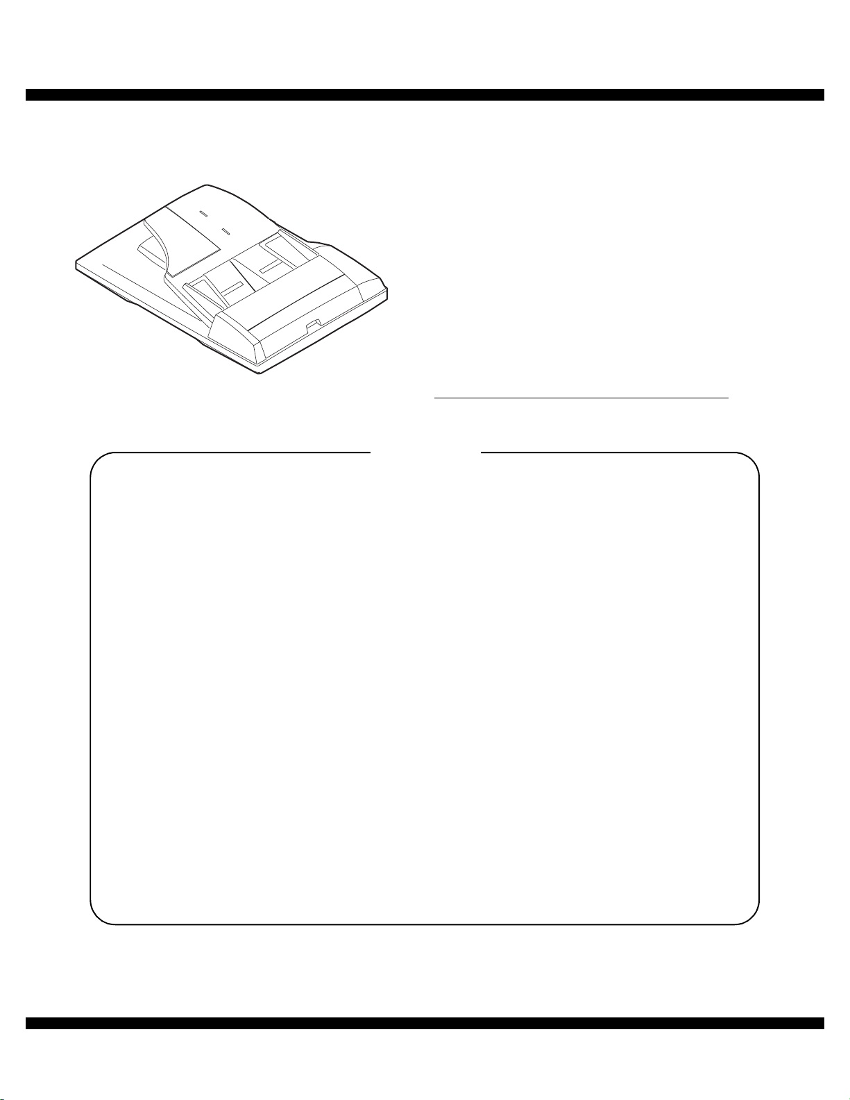
[1] PRODUCT OUTLINE
This machine is a duplex document auto feeder attached to a digital
copier.
It feeds originals automatically to allow continuous copying.
[2] SPECIFICATIONS
AR-RP6 AR-SP6
Document set direction Face up
Document set position Right/Center reference
Document transport
system
Document feed sequence Top take-up feed
Document size AB series: A3 ~ A5
Document weight 56 ~ 90g/m
Document set quantity Max. 40 sheets (Stack range: within 4mm)
Dimensions 583mm (W) x 435mm (D) x 133mm (H)
Weight About 5.4 kg About 5.0 kg
Power source S up p l i ed f r o m th e
Power consumption 26.4W 21W
Document size detection On the document feed tray
Detection size Japan: A3, B4, A4, A4R, B5, B5R,
Mixture of different
document sizes
Document reverse Allowed
Display section (LED) None
Document exchange
speed
Sheet through type
Inch series: 11 x 17 ~ 8.5 x 5.5
2
, 15 ~ 24lbs
2
: Set capacity = 30 sheets)
(90g/m
copier. (DC 24V)
Inch series: 11 x 17, 8.5 x 14, 8.5 x 11,
EX AB series: A3, B4, A4, A 4R, A 5 , B5,
Mixture paper feed: Not available
Random paper feed: Not available
(without 8.5 x 5.5)
S 3 S, 16 sheets/min (AR-160M)
S 3 S, 20 sheets/min (AR-200M)
Supplied from the
copier. (DC 24V, 5V)
A5
8.5 x 11R, 8.5 x 5.5
B5R, A5R
Not allowed
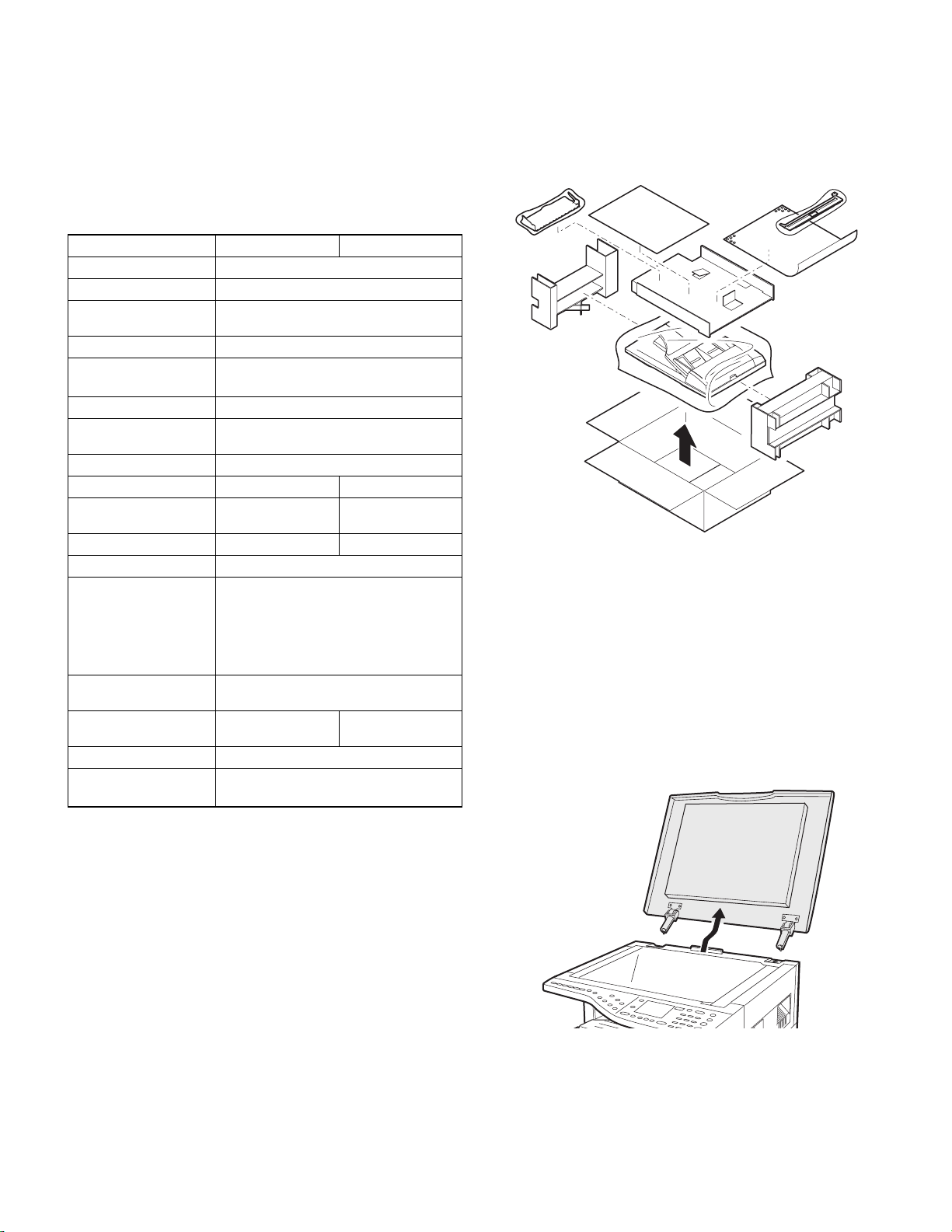
[3] UNPACKING AND INSTALLATION
1. Unpacking
For unpacking, refer to the figure below.
2. Installation
Turn the main switch of the copier to the “OFF” position and then
remove the power plug of the copier from the outlet.
1. Remove th e document cover.
Lift the document cover from the copier and tilt it to the rear side to
remove it.
AR-SP6/RP6 PRODUCT OUTLINE
– 1 –
Page 3
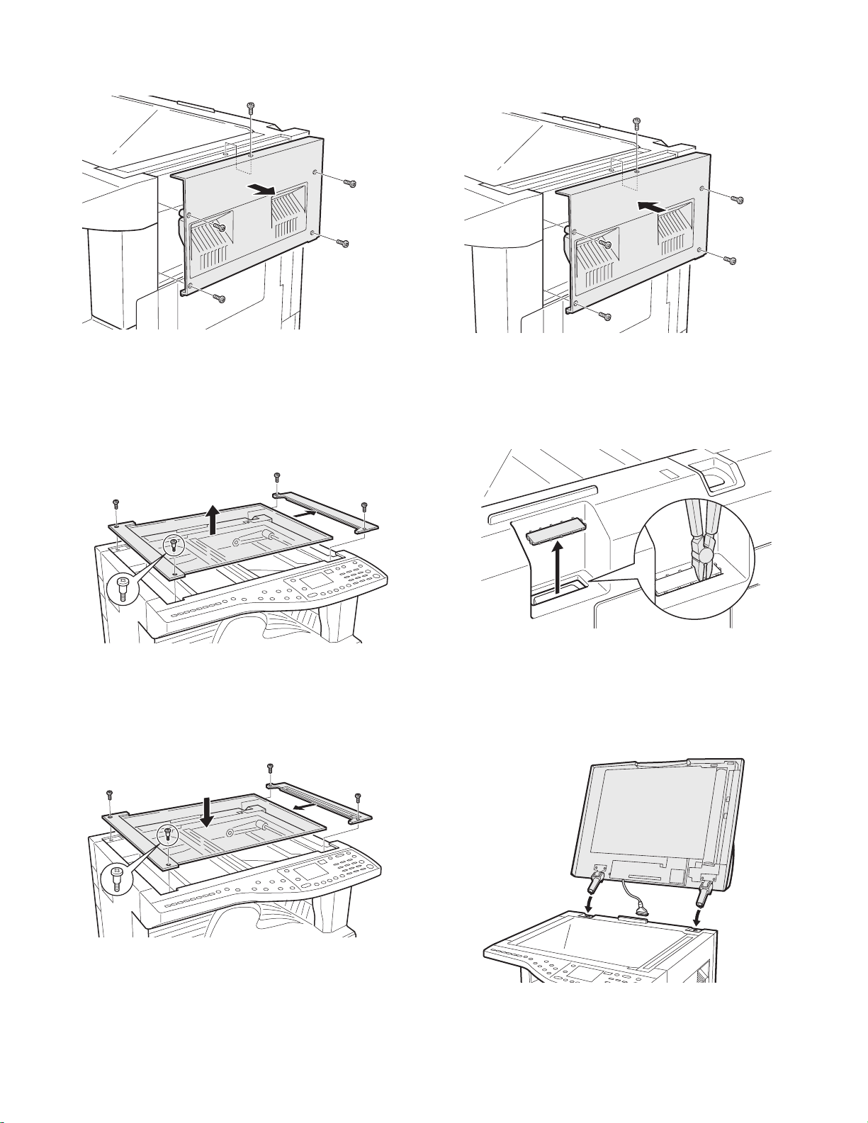
2. Remove the right cabinet.
Remove the screws and remove the right cabinet.
5. Attach the right cabinet.
Reattach the right cabinet to its original position and fix it with the
screws.
3. Remove the document glass and the right document
glass holder.
Remove the screws, remove the document glass from the copier, and
then remove the right document glass holder.
4. Attach the SPF glass holder.
Fit the SPF glass holder to the document glass.
Attach the document glass to the copier and fix it with the screws.
6. Cut out the cut-out portion.
Cut out the cut-out portion of the rear cabinet with nippers or the like.
At this time, be careful about the orientation of the nippers so that the
cut plane of the rear cabinet is flat.
7. Attach the automatic document feeder.
Insert the hinge portions of the document feeder into the mounting portions of the copier by holding the feeder at an angle toward the rear
side.
AR-SP6/RP6 UNPACKING AND INSTALLATION
– 2 –
Page 4
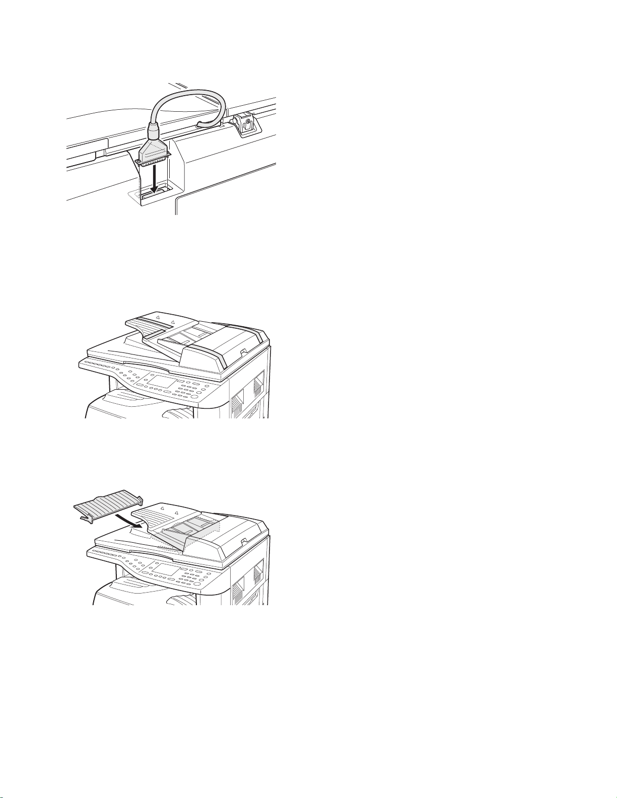
8. Connect the relay connector.
Connect the harness of the automatic document feeder to the connector of the copier and tighten the screws on the connector.
9. Remove the filament tape.
Remove the filament tape located in the positions shown in the illustration.
Insert the power plug of the copier to the outl et and turn on
the main switch of the copier.
11. Adjust the white compensation pixels.
• Open the automatic document feeder, execute simulation 63-7 referring to the service manual, and adjust the automatic white compensation pixels of the document feeder.
12. Check the copy magnification ratio.
• Set an original on the document glass and copy it.
Then, set an original in the document feeder tray and copy it.
• If the magnification ratio of the copy from the document feeder is different from that of the copy from the document glass, execute simulation 48-5 to carry out adjustment referring to the service manual.
13. Check the center displacement.
• Set an original on the document glass and copy it.
Then, set an original in the document feeder tray and copy it.
• If the center of the copy image from the document feeder is different
from that of the copy image from the document glass, execute simulation 50-12 to carry out adjustment referring to the service manual.
14. Check the top end position.
• Set an original on the document glass and copy it.
Then, set an original in the document feeder tray and copy it.
• If the top end position of the copy image from the document feeder is
different from that of the copy image from the document glass, execute simulation 50-06 to carry out adjustment referring to the service
manual.
10. Attach the intermediate tray. (AR-RP6 only)
Insert the intermediate tray all the way into the document feeder.
AR-SP6/RP6 UNPACKING AND INSTALLATION
– 3 –
Page 5
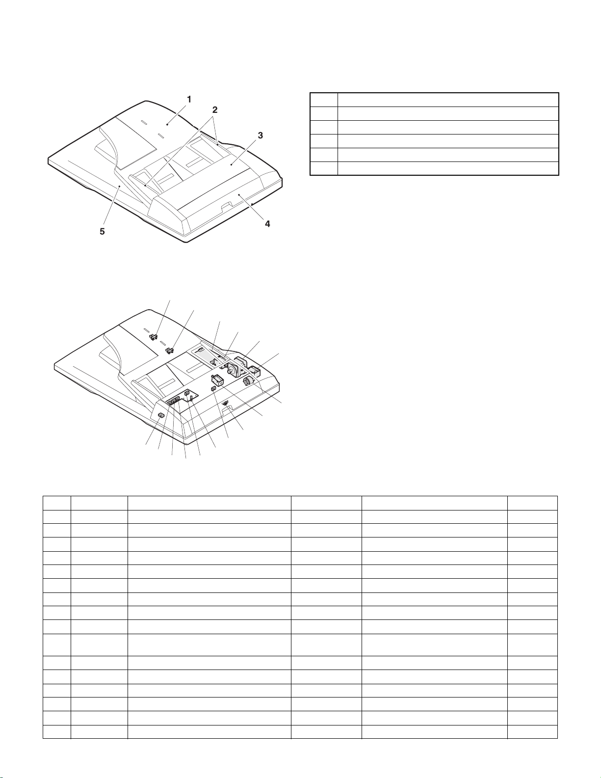
[4] EXTERNAL VIEW AND INTERNAL STRUCTURE
1. External view
No. Name
1 Document set tray
2 Document guide
3 Document feed section cover
4 Document transport section cover
5 Document exit section
2. Internal structure
14
13
12
11
10
8
9
6
7
15
5
4
3
16
2
1
Sensor, detector, etc.
No. Code Name Type Function/Operation Note
1 W0 Document set sensor Photo transmission Detects presence of documents.
2 COVER Open/close sensor Photo transmission Detects open/close of the paper feed unit.
3 W1 Document width sensor (A4R, LTR, A5) Photo transmission Detects the document width on the tray.
4 W2 Document width sensor (B4, B5) Photo transmission Detects the document width on the tray.
5 W3 Document width sensor (WL, TR, A5R, A4, LT) Photo transmission Detects the document width on the tray.
6 PSOL Pickup solenoid — —
7 PAPER Paper entry sensor Photo transmission Detects presence of documents.
8 RSOL Pressure release solenoid — — AR-RP6 only
9 CLH Transport clutch — —
10 MOT SPF (RSPF) motor Stepping motor Drives document feed on the tray, trans-
11 GSOL Gate solenoid — — AR-RP6 only
12 — Interface PWB — —
13 L1 Document length detection SW (Short) Photo transmission Detects the document length on the tray.
14 L2 Document length detection SW (Long) Photo transmission Detects the document length on the tray.
15 COVER OPEN Book sensor Photo transmission Detects the SPF (RSPF) float.
16 PO Paper exit sensor Photo transmission Detects presence of documents.
port, and paper exit roller.
AR-SP6/RP6 EXTERNAL VIEW AND INTERNAL STRUCTURE
– 4 –
Page 6

[5] OPEREATIONAL DESCRIPTIONS
1. Major parts of the paper feed section 2. Out line of operations
1 2 3,4 5 6 7 8
12
No. Part name Operation Note
1 Document length
sensor (L2)
2 Document length
sensor (L1)
3 Document set
sensor (W0)
4 Document width
sensor (W1, W2, W3)
5 Pickup roller Picks up documents.
6 Paper feed roller Feeds and transports docu-
7 Paper entry sensor
(PAPER)
8 PS roller Makes synchronization
9 PS follower roller Makes synchronization
10 Transport roller Transports documents.
11 Transport follower
roller
12 Paper exit sensor
(PO)
13 Paper exit follower
roller
14 Paper exit roller Discharges documents.
15 Reverse gate Opens/closes the document
16 Paper exit gate Separate document exit to the
17 Intermediate tray Discharges documents to the
Detects the document length
on the tray.
Detects the document length
on the tray.
Detects presence of documents.
Detects the document width.
ments.
Detects transport of docu-
ments.
between the document lead
edge and the image lead edge.
between the document lead
edge and the image lead edge.
Transports documents.
Detects transport of documents.
Discharges documents.
reverse path.
intermediate or the paper exit
tray.
intermediate tray during document reverse.
AR-RP6
only
AR-RP6
only
910111314 151617
■AR-RP6 (RSPF)
[Duplex documents]
1) Document set (Document set sensor ON)
4
2) Document size detection (Document width sensors W1, W2, W3
detect the document width, and document length sensors L1, L2 detect the
document length.)
4
3) Copier COPY key ON
4
4) RSPF motor ON
4
5) Pickup solenoid ON
4
6) Pickup roller and paper feed roller rotation
4
7) Paper entry sensor detects the document presence.
4
8) PS roller rotation
4
9) Copying (Front surface of document)
4
10) Transport roller rotation
4
11) Paper exit roller rotation
4
12) Paper exit gate falls down.
(Documents are discharged to the intermediate tray.)
4
13) Reverse gate falls down.
4
14) Paper exit roller reverse rotation
(Documents are fed to the reverse path.)
4
15) Paper entry sensor detects document presence.
4
16) PS roller rotation
4
17) Copying (Back surface of document)
4
18) Transport roller rotation
4
19) Paper exit roller rotation
4
20) Paper exit gate falls down
(Documents are discharged to the intermediate tray.)
4
21) Reverse gate falls down.
4
22) Paper exit roller reverse rotation
(Documents are fed to the reverse path.)
4
23) Paper entry sensor detects document presence.
4
24) PS roller rotation
4
25) Paper exit roller rotation
4
26) Paper exit gate lifts up.
4
27) Documents are fed to the paper exit tray.
4
28) Next document 3 (YES) 3 Go to 4).
4 (NO)
29) RSPF motor OFF
AR-SP6/RP6 OPEREATIONAL DESCRIPTIONS
– 5 –
Page 7

■AR-SP6 (SPF)
3. Document size detection
1) Document set (Document set sensor ON)
4
2) Document size detection (Document width sensors W1,
W2, W3 detect the document
width, and document length sensors L1, L2 detect the document
length.)
4
3) Copier COPY key ON
4
4) SPF motor ON
4
5) Pickup solenoid ON
4
6) Pickup roller and paper feed roller rotation
4
7) Paper entry sensor detects the document presence.
4
8) PS roller rotation
4
9) Copying (Front surface of document)
4
10) Transport roller rotation
4
11) Paper exit roller rotation
4
12) Documents are fed to the paper exit tray.
4
13) Next document 3 (YES) 3 Go to 4).
4 (NO)
14) SPF motor OFF
1) Document size detection with the document set tray
When documents are set on the document set tray in the auto selection
mode of paper/copy magnification ratio, the document size is detected
and paper and the copy magnification ratio are automatically selected.
When different sizes of documents are set, the max. size is detected.
The document width is detected by the document width sensors (W1,
W2, W3), and the document length is detected by the document length
sensors (L1, L2) to identify the document size. Judgement of the document size is made in a certain timing after detecting the document w ith
the document set sensor (W0).
Document
length sensor
AB series
Inch
series
Document set
size and set
direction
A5 onnnn
B5 oonnn
A5R nnnnn
A4 ooonn
B5R nnnon
A4R onnon
8.5” x 13” onnoo
B4 onnoo
A3 ooooo
8.5” x 5.5” onnnn
8.5” x 5.5”R nnnnn
11” x 8.5” ooonn
11” x 8.5”R onnon
8.5” x 13” onnoo
8.5” x 14” onnoo
11” x 17” ooooo
Document width sensor
W1 W2 W3 L1 L2
Note: Detection sensor ON: o, OFF: n
AR-SP6/RP6 OPEREATIONAL DESCRIPTIONS
– 6 –
Page 8

[6] ADJUSTMENTS
(1) Auto white correction pixel adjustment
[Function]
The white correction start pixel position is automatically adjusted.
This adjustment is performed after the lens unit is replaced.
[Operation]
Open the SPF (RSPF) unit and press the [OK] key.
7-segment indicates the order number of the pixel of the white sheet for SPF (RSPF)
exposure correction in the SPF (RSPF) position.
It will display on 7-segment, if values are 93-299, and data are written into the EEPROM.
It will display on 7-segment, it values are 0-92 or 230-999, and data are not written into
the EEPROM.
It will display "--" on 7-segment, it values is 1000 or larger, and data are not written into
the EEPROM..
[CA] key: Cancels the test command.
[Interruption] key: Shifts to the sub code entry menu.
The SPF white correction start pixel = Displayed pixel position - 34
Interruption is inhibited during execution.
If the simulation is executed with the SPF unit closed, an error is resulted.
During execution,"EXEC" is highlighted
(2) Magnification ratio adjustment
Note: • When performing this adjustment, check that the CCD unit is
properly installed.
• When performing this adjustment, check that the OC mode
adjustment in copying is completed.
1) Place a scale on the document table as shown be low, and make a
normal copy to make a test chart.
(3) Document off center adjustment
Note: When performing this adjustment, check that the paper off-cen-
ter is properly adjusted.
1) Set the center position adjustment test chart (made by yourself) on
the SPF (RSPF).
<Adjustment specifications>
Draw a line in the center of paper. (In the scanning direction)
2) Make a normal copy from the manual feed tray, and co mpare the
copy and the test chart.
If an adjustment is required, perform the following procedures.
3) Execute SIM 50-12.
4) The current off-center adjustment value is displayed on the display
section in two digits.
5) Enter the set value and press the START key.
The entered correction value is started and a copy is made.
<Adjustment specifications>
Mode Specification SIM Set value
Document
off-center
(AR-RP6)
Document
off-center
(AR-SP6)
Simplex:
Center
Duplex:
Center
m
m
3.0mm
3.5mm
SIM 50-12
TEXT:
SPF surface
PHOTO:
SPF back
AE: Surface
TEXT: Back
Add 1:
0.1mm shifted to
R side.
Reduce 1:
0.1mm shifted to
L side.
Set
range
1 ~ 99
(4) Image lead edge position adjustme nt
1) Set a scale on the OC table as shown below.
Note: Since the printed paper is used as the test chart,
place the scale in parallel to both sides.
2) Set the test chart to the SPF (RSPF) and make a normal copy.
3) Compare the copy and the test chart.
If an adjustment is needed, perform the following procedures.
4) Execute SIM 48-5.
5) The current correction value is displayed on the display section in
two digits.
6) Enter the set value, and press the START key.
The entered correction value is stored and a copy is made.
7) Change the TEXT mode.
The TEXT lamp lights up, and the current correction value of the
back surface sub scanning direction magnification ratio is displayed
on the display section in two digits.
8) Enter the set value, and press the START key.
The entered correction value is stored and a copy is made.
<Adjustment specifications>
Mode Spec SIM Set value
Magnification
ratio adjustment
Normal:
m 1.0%
SIM 48-5
AE: Surface
TEXT: Back
Add 1:
Reduce 1:
0.1% increase
0.1% decrease
Set
range
1 ~ 99
Note: Since the printed paper is used as the test chart,
place the scale in parallel to both sides.
2) Make a copy, and use the copied paper as the document and make
a copy from SPF (RSPF) again.
3) Check the copied paper. If an adjustment is required, perform the
following procedures.
4) Execute SIM 50-6.
5) Set the SPF/RSPF lead edge position set value so that the image
similar to the adjusted image at the OC image lead edge position
described previously is printed.
<Adjustment specifications>
Adjustment
mode
Image
lead edge
position
SIM Set value Specification
SIM 50-6 1step: 0.1mm shift Lead edge void:
1 ~ 4mm
Image loss:
Set
range
1 ~ 99
3mm or less
AR-SP6/RP6 ADJUSTMENTS
– 7 –
Page 9

[7] DISASSEMBLY AND ASSEMBLY
1. External fitting section
Note: Turn the paw in the arrow direction.
3
2) Document feed section cover
2
2
1
1
1
2
3) Sensor PWB
1
2. Paper feed unit section
1) Paper feed unit
3
4
2
2
AR-SP6/RP6 DI SASSEMBLY AND ASSEMBLY
– 8 –
Page 10
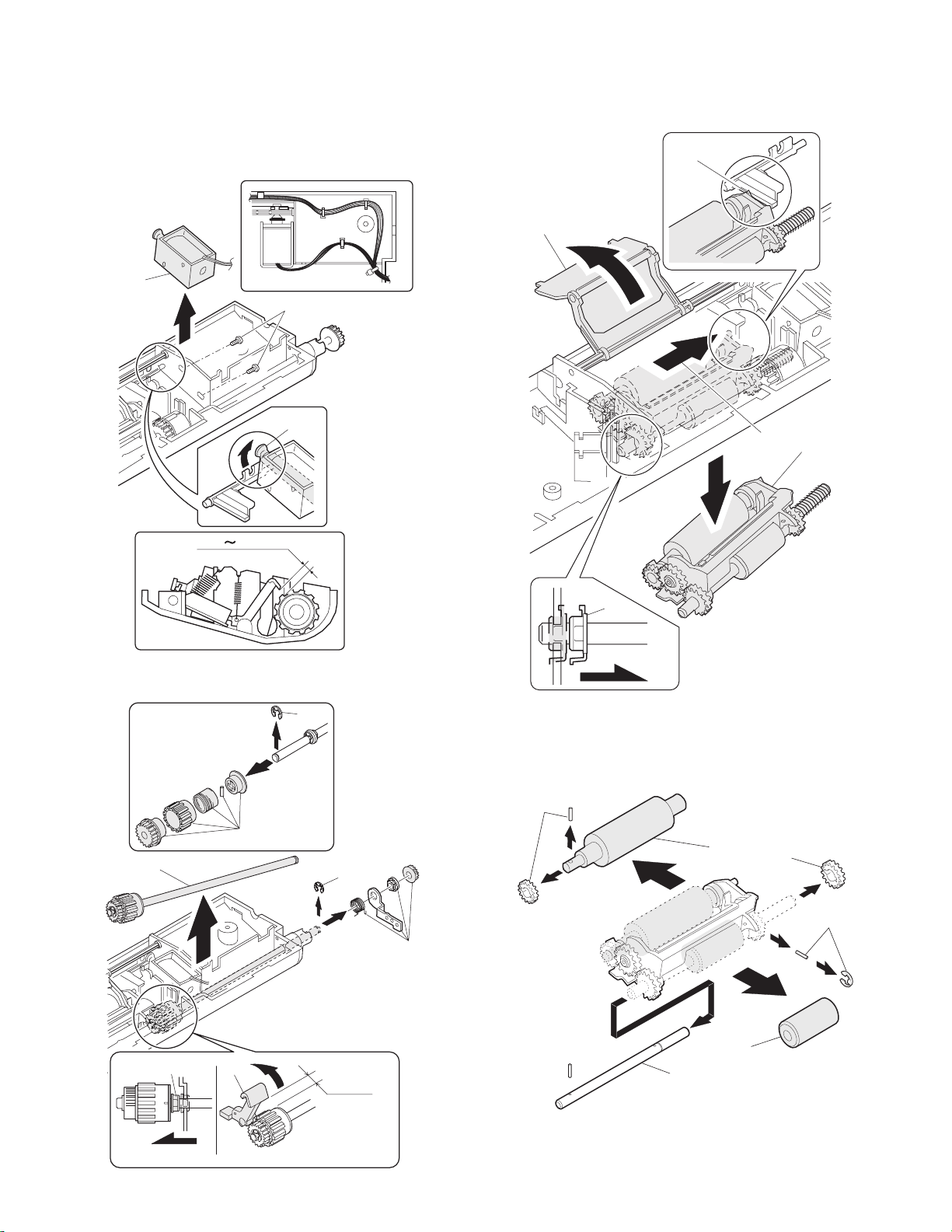
4) Pickup solenoid
Note: Remove section A of the pickup solenoid from the solenoid arm
groove.
When assembling, adjust the spacing between the clutch latch
and sleeve with the pick-up solenoid pulled. The size should be
the distance from the tip of the clutch latch and the root of the
clutch sleeve latch.
2
1
A
6) Pickup roller ass’y
Note: When assembling the pickup roller ass’y 4, check that rib A is on
the rib of the solenoid arm.
A
1
2
4
2.5 4.5mm
5) Clutch gear ass’y
5
3
6
7) Pick up roller, paper feed roller
4
6
1
2
3
1
1
3
4
From Edge pawl
2.5~4.0
1
AR-SP6/RP6 DI SASSEMBLY AND ASSEMBLY
– 9 –
2
Page 11

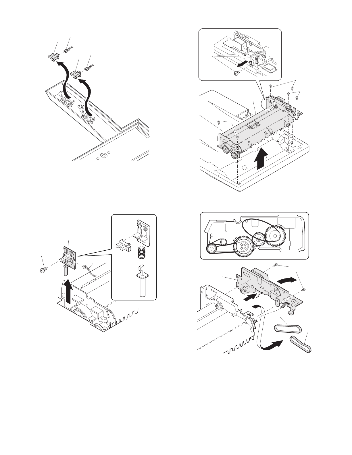
3. Interface PWB
5. Document tray section
1
1) Document tray
1
2
A
2
3
1
B
1
B
1
A
2) Rack cover
■■■■AR-RP6
1
1
1
4. Gate solenoid
■■■■AR-RP6 only
2
1
Bearing
■■■■AR-SP6
1
1
1
2
Note: When assembling, check that the paper exit gate hook is set in
the solenoid groove.
When assembling, the bearing D-cut surface shuold be faced
down.
AR-SP6/RP6 DI SASSEMBLY AND ASSEMBLY
– 10 –
Page 12
3) Document length sensor SW
2
1
2
1
2) Drive frame unit
1
1
1
2
1
6. Drive frame section
1) Book sensor
2
1
3) Drive frame ass’y and drive belt
3
1
2
3
4
AR-SP6/RP6 DI SASSEMBLY AND ASSEMBLY
– 11 –
Page 13
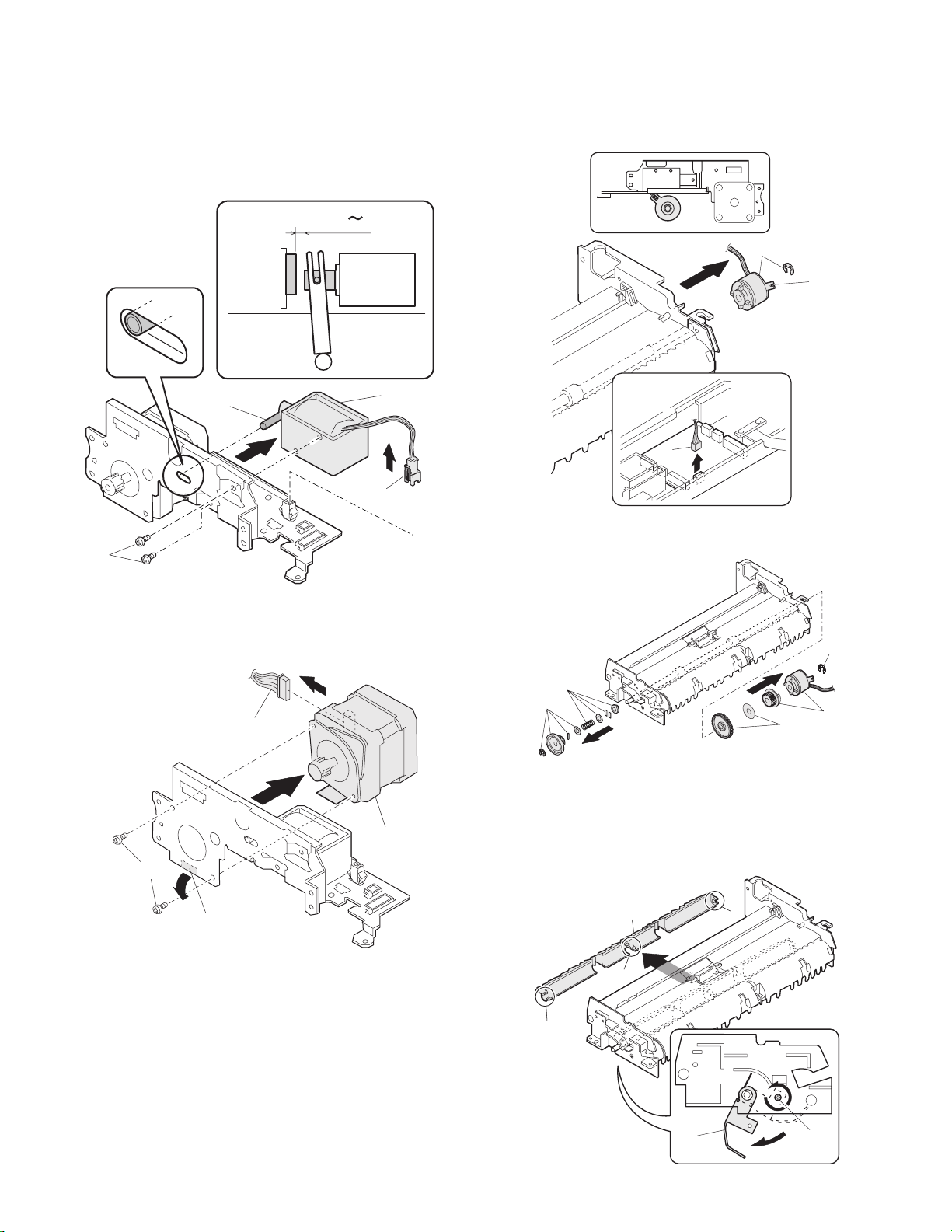
4) Pressure release solenoid
■■■■AR-RP6 only
Note: Make sure the spring pin A is inserted into the slot.
Make sure that the clearance between the position at which force
is applied and the sound deadening sponge is 0.5 ~ 2 mm when
the pressure release solenoid plunger is pulled toward the solenoid side.
0.5 2mm
7. Transport section
1) Clutch
Note: When assembling, check that the rib is in the clutch groove A
and fix it with E-ring.
2
A
A
2
5) RSPF motor / SPF motor
1
3
3
1
1
2) Transport roller gear
1
1
1
3) Reverse gate
■■■■AR-RP6 only
4
Note: When assembling the inversion gate, apply grease G-484 on the
area A.
1
1
2
A
AR-SP6/RP6 DI SASSEMBLY AND ASSEMBLY
– 12 –
3
A
A
2
1
Page 14

4) Transport roller
Note: Note that the spring will come off when removing.
■■■■AR-RP6
5) PS roller
1
1
1
■■■■AR-SP6
1
2
1
1
6) Paper feed paper guide lower
Note: When assembling, check that the paper feed paper guide lower
is securely set to rib A and boss B.
+
1mm
-
0 0.5mm
2
1
1
1
AR-SP6/RP6 DI SASSEMBLY AND ASSEMBLY
– 13 –
B
1
A
Page 15

7) Paper feed paper guide upper
[8] MAINTENANCE
1
8) Paper exit roller
2
1
1. Maintenance parts
No. Name Work item Service call Remark
1 Pickup roller Cleaning o
2-1 Separation unit Cleaning o Replace when
2-2 Front separation
sheet
3 Paper feed roller Cleaning o
4 PS roller Cleaning o
5 Transport roller Cleaning o
6 Paper exit roller Cleaning o
Cleaning o
1
worn down.
3
1
2
8. Hinge L
Note: When assembling the hinge L, reference is based on the mark of
base tray and the center line of the 5 lines of the hinge L
extended horizontally.
1
1
2
1
2-2
2-1
6
5
4
Note: When performing maintenance, refer to [7] DISASSEMBLY AND
ASSEMBLY.
AR-SP6/RP6 MAINTENANCE
– 14 –
Page 16
D
1
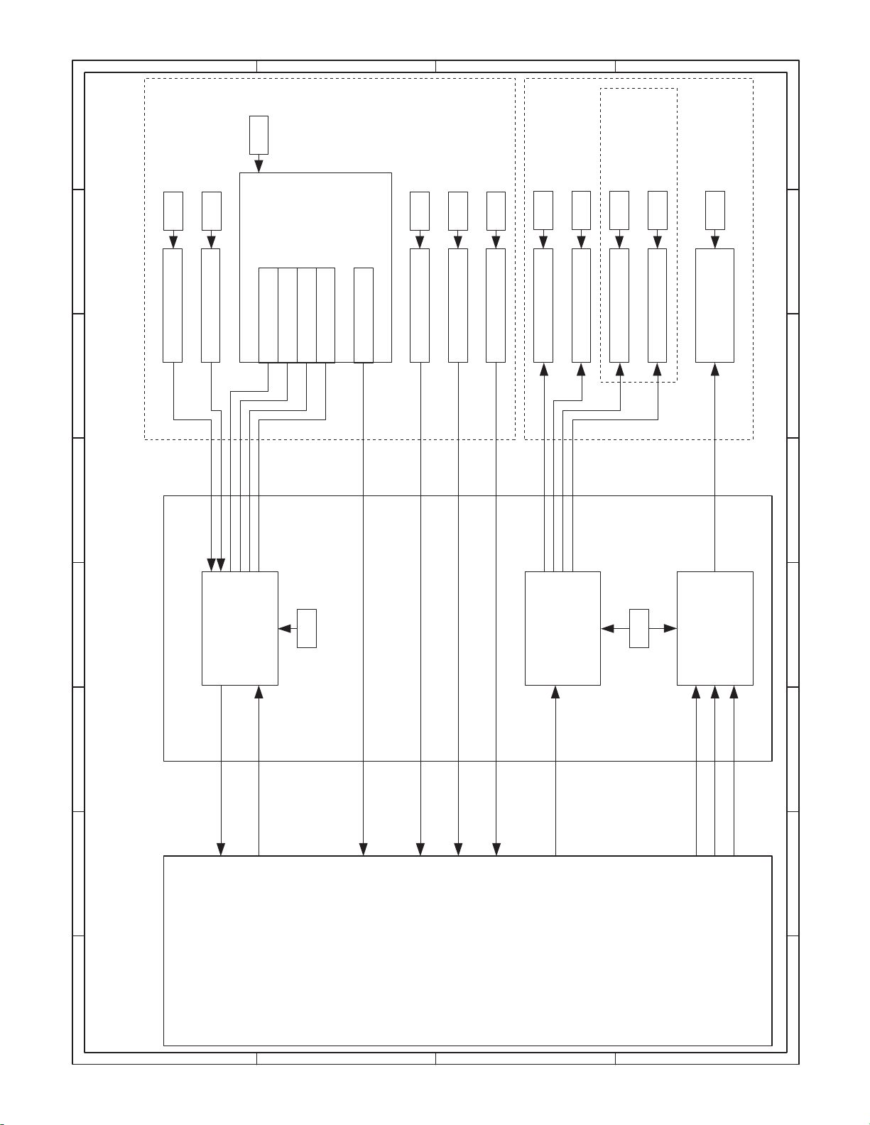
SENSOR
5V
C
B
SOL/CLU
A
RSPF ONLY
5V
5V
24V
24V
5V
24V
24V
24V
24V
24V
234
L2
L1
W0W1W2
SPF SENSOR PWB
W3
PAPER
/SPFOUT
SPFOPEN
/CLH
/PSOL
/RSOL
/GSOL
MOTOR
(A,B,/A,/B)
2 1
/SPFCOVER
3
5
DATA
SELECTOR
5V
TRANSISTOR
24V
ARRAY
MOTOR
DRIVER
5 4
SPF/RSPF INTERFACE PWB
678
7 6
[9] ELECTRICAL SECTION
1. Block diagram
PEGASUS
(MCU PWB)
D
YSPF
/SPFCOVER
SEL(A#,B#,C#)
C
AR-SP6/RP6 ELECTRICAL SECTION
PAPER
– 15 –
/SPFOUT
SPFOPEN
SPF(CLH,PSOL,RSOL,GSOL)
B
/MODA,/MODB)
SPF(MODA,MODB,
A
PDOWNA
PDOWNB
8
Page 17

D
C
B
A
12345678
DSPF ONLY
ORIGINAL TRAY
Sensor PWB
PAPER FEED UNIT
W0
5v
1
2
BL
OR
W2
W1
4
3
PLBRLB
W3
5
SPFCOVER
SGND7
6
GY
PK
SPFPSOL
L1
321
ORLBGY
L2
321
ORGYBL
PAPER
(Paper Entry Sensor)
213
GYBRPL
SPFRSOL
SPFGSOL
A
3
1
BLLBPK
/B2/A
PLUSE MOTOR
4B
PLRDRD
24V1624V1
5
2 1
PHR-7
BLORPLBRLBGYPK
2
3
5V
W1
W0 17
BU7P-TR-P-H
6
5
BLORPLBRLBGYPK
PHDR-20
BLORPLBRLBGYPK
7
1
5
5VW0W1
CN6
B20B-PHDSS
PHR-3
DF3-3S-2C
ORLBGY
PHNR-7-HPHNR-7-H
SGND 71
SPFCOVER 62
W3 53
W2 44
1
2
SPFPSOL
24V1
BU2P-TR-P-H
2
1
BL
RD
PHNR-2-H
BU6P-TR-P-H
2
L1
5V 16
5
ORLBGY
3
SGND
4
ORGYBL
5V 43
ORGYBL
PHNR-2-H
BL
RD
9
20314
SGND
W2
W3
SPFCOVER
11
/PSOL 6
24V1
ORLBGY
2
15
L1
5V
16
SGND
ORGYBL
45V
DF3-3S-2C
PHNR-6-HPHNR-6-H
SGND 61
L2 52
1
SPFRSOL
1
LB
2
SMR-02V-N(JST)
24V1
2
RD
SMP-02V-BC(JST)
GYBRPL
17SGND
L2 13
18SGND
pull up 8
LB
19PAPER
PHR-2
RD
CN4
B2B-PH-K-S
2/GSOL
24V1 1
1224V1
/RSOL 10
PHR-6
PHR-7
BLLBPK
CN3
B7B-PH-K-S
3
PL
RD
RD
3/B
2/A
5N.C.
4B
1A
624V1
724V1
2. Actual wiring diagram
PAPER
1
CN5
B26B-PHDSS
25
PAPER
MCU PWB Interface PWB
/SPFCOVER
SELA#
3
2
20
16
/SPFCOVER
SELA#
D
SPFMODB
SELB#
5
4
17
SPFMODB
SELB#
/SPFMODB
SELC#
3 7 6
/SPFMODB
SELC#
N.C.6SGND
SGND7YSPF
9108
12
13-18
N.C.
SGND
SGND
11
15
YSPF
SPFOPEN
5V
12
13
24
SPFOPEN
5V
SPFGSOL
SPFMODA
15
16
22
5
SPFGSOL
SPFMODA
/SPFMODA
SPFRSOL
181719
4 921
/SPFMODA
SPFRSOL
SPFCLH
SPFCLH
PDOWNA
PDOWNA
/SPFOUT
14
19
/SPFOUT
C
AR-SP6/RP6 ELECTRICAL SECTION
PDOWNB
SPFPSOL
212220
1023 8
PDOWNB
SPFPSOL
– 16 –
PGND
23
11
PGND
PGND
24
14
PGND
SPF0PEN2
SGND
N.C.2
24V1
24V
24V
25
26
CN7
1
B3B-PH-K-S
/CLH
3
CN1
BL
FG
PHR-3
SRA-21T-4
SRA-21T-4SRA-21T-4
BL BL
BL
1
2
26
FG
24V
24V
SPFCLH
5V
3
1
B3B-PH-K-R(RD)
GY
OR
BRBR
PHR-3(RD)
DF3-3S-2C
GY
OR
123
/SPFOUT2
SGND
1
CN2
B3B-PH-K-K(BK)
GR
GY
PHR-3(BK)
DF3-3S-2C
GYORGR
123
5V
3
OR
EARTH PLATE(SPF ONLY)
8 7 6 5 4
SPFOPEN
(Book Sensor)
B
/SPFOUT
(Paper Exit Sensor)
A
Page 18

D
CN2-6 (B3)
CN6-3 (B2)
CN2-10 (B3)
CN3-3 (A2)
C
B
A
12345678
/CLH
/RSOL
/GSOL
/PSOL
24V1
C115
0.047u/50V
C114
0.047u/50V
5V
1C2C3C4C5C6C7C
1B2B3B4B5B6B7B
IC2
SPFCLH
SPFPSOL
(A4) CN1-21
(A4) CN1-19
IC101
COM
GND
TD62003AP
SPFRSOL
SPFGSOL
(A4) CN1-17
(A4) CN1-15
CN1-11 (A4)
YSPF
ZD102
UDZ5.6
C120
0.1u/25V
Y
W
VCC
D0D1D2D3D4D5D6D7ABC
GND
CN7-4 (B2)
CN7-3 (A2)
CN7-2 (B3)
CN7-1 (B3)
CN7-6,7 (B3)
BA/B
/A
2 1
Pattern width: 0.5mm or above
C1
47u/35V
3
C104
R107
R101
C107
0.047u/50V
24V1
7.5KJ
C113
7.5KJ
2200pF/50V
2200pF/
50V
C110
C103
3300pF/50V
0.047u/50V
IC1
R104
C108
0.1uF/25V
1KJ
Vmm
CrA
CrB
R102 2.4k
OUT A
VsA
R1 1.5(1W)
OUT B
RsA
OUT /A
VrefA
NCNCNCNCNCNCPG
OUT /B
VrefB
RsB
VsB
In /A
In A
R105
R2 1.5(1W)
R106 2.4k
In /B
1KJ
C112
LG
PG
PG
In B
0.1uF/25V
C111
MTD1361
3300pF/50V
/SPFMODB
/SPFMODA
SPFMODA
(C4) CN1-6
(C4) CN1-16
(C4) CN1-18
Pattern width: 1.0mm or above
SPFMODB
(C4) CN1-4
CN1-5 (A4)
CN1-7 (A4)
CN1-3 (A4)
SELA#
SELC#
SELB#
C118
1000p/50V
C117
1000p/50V
C119
1000p/50V
ZD103
UDZ5.6
ZD101
UDZ5.6
ZD104
UDZ5.6
G
74HC151
R111
R113
R112
R115
R114
R117
R116
10K
10K
10K
10K
10K
10K
10K
Document size senser
(A3) CN2-9
(A3) CN2-3
(A3) CN2-7
W0W2W3W1L2
L1
(A3) CN2-5
(A3) CN2-15
(A3) CN2-13
5V
3-1. Interface PWB (1/2)
3. Circuit Diagram
D
C122
C121
C124
C123
C126
C125
/SPFDTC
1000pF/50V*7
JP1
DSPF
Y
W3
W2
W1
W0
/SPFDTC (L)
L2
L1
SPF(H)/DSPF(L)
LHLHLHL
SELA
L
SELB
LLL
SELC
Senser Mtorix
L
H
L
L
H
H
H
H
L
H
HHH
C
AR-SP6/RP6 ELECTRICAL SECTION
– 17 –
C2
$PIN0
C109
0.1u/25V
10k
PDOWNA
(C4) CN1-20
10u/16V
110F
R110
Q102
DTC114EK
10k
10k
Q101
DTC114EK
10k
PDOWNB
(C4) CN1-22
8 7 6 5 4
A
5V
R103
620F
TP103
$PIN0
R109
430F
$PIN0
TP102
R108
390F
1
TP101
B
Page 19

D
C
B
A
12345678
CN1-2 (C4)
(E4)
(D4)
/PSOL
/RSOL
8
1012141618
/SPFCOVER
20
R119
R118
470
470
246
5V
123
CN7
B3B-PH-K-S
24V1
/CLH
(E4)
2 1
1357911131517
CN6
5V
24V1
W3
(B3)
(B3)
CN4-2 (B2)
(C1)
CN2-20 (B3)
(B2) CN5-2
(C1)
/SPFOUT
SPFMODB
SPFOPEN
/SPFMODB
/SPFCOVERPAPER
W1W2W0
(B3)
(B3)
(C1)
(C1)
SPFMODA
/SPFMODA
L2
L1
(B3)
(B3)
(B1)
(B1)
PDOWNA
PDOWNB
19
PAPER
CN1-1 (A4)
24V1
F1
B20B-PHDSS
C127
0.1u/25V
ICP-N38
C105
0.047u
C106
0.047u
CN1-14 (C4)
C102
0.1u/25V
/SPFOUT
5V
123
CN2
B3B-PH-K-E(BL)
CN1-12 (C4)
C101
0.1u/25V
SPFOPEN
5V
123
CN1
B3B-PH-K-R(RD)
3
246
CN5
135791113151719212325
SELA#
CN2-19 (A3)
3-2. Interface PWB (2/2)
D
8
101214161820222426
SELB#
SELC#
YSPF
5V
(E3)
(E3)
(E3)
(E3)
SPFGSOL
SFPRSOL
SPFCLH
5V
(D4)
(D4)
(D4)
1
2
B26B-PHDSS
C116
0.1u/25V
+
C3
10u/16V
SPFPSOL
(D4)
C
CN4
B2B-PH-K-S
24V1
/GSOL
(E4)
CN3
24V1
1234567
B7B-PH-K-S
A/A/B
B
(E4)
(E4)
(E4)
(E4)
8 7 6 5 4
B
A
AR-SP6/RP6 ELECTRICAL SECTION
– 18 –
Page 20

D
C
B
A
12345678
2 1
3
3-3. Sensor PWB
D
C
AR-SP6/RP6 ELECTRICAL SECTION
– 19 –
8 7 6 5 4
B
A
Page 21
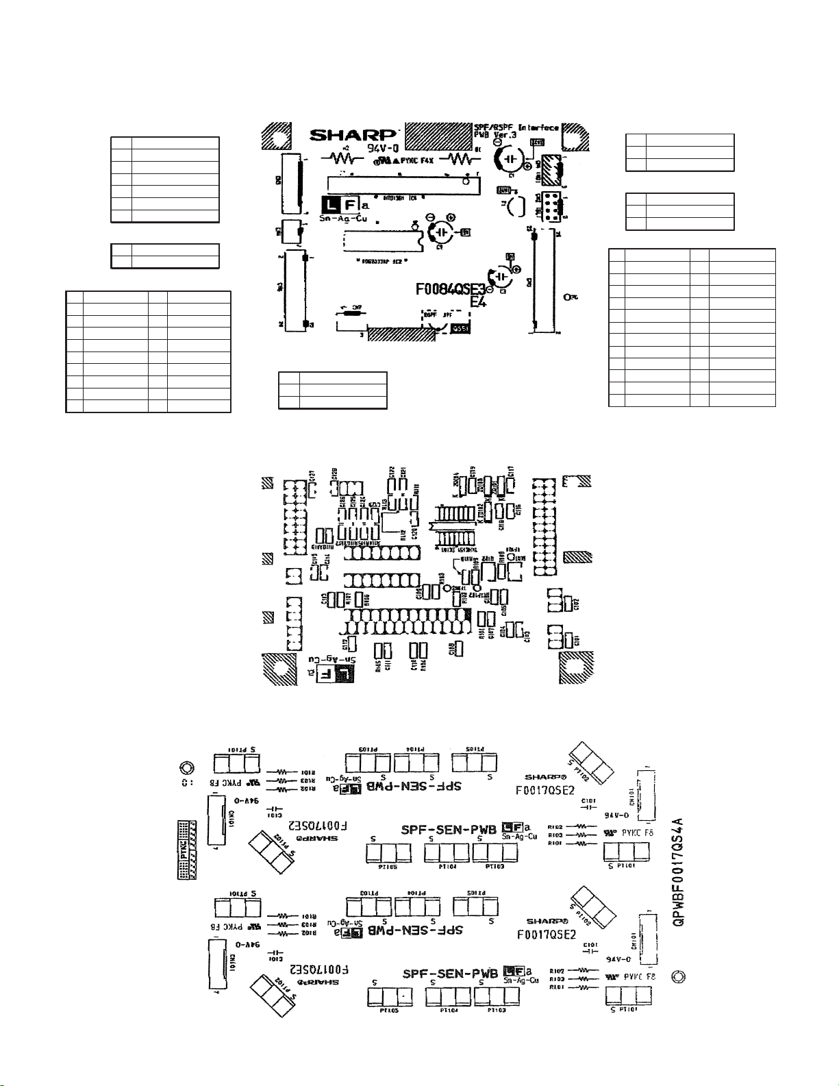
4. Parts arrangement
4-1. Interface PWB
a. Parts surface
CN3(B7B-PH-K-S)
1
2
3
4
5
6
7
CN4(B2B-PH-K-S)
1
2
CN6(B20B-PHDSS)
25V15V
45V3W3
6 /PSOL 5 W0
8 Pull up 7 W1
10 /RSOL 9 W2
12 24V1 11 24V1
14 SGND 13 L2
16 SGND 15 L1
18 SGND 17 SGND
20 SPFCOVER 19 PAPER
A
/A
/B
B
N.C.
24V1
24V1
24V1
/GSOL
CN7(B3B-PH-K-S)
1 24V1
2 N.C.
3 /CLH
CN1(B3B-PH-K-R RD)
1 SGND
2 SPFOPEN
35V
CN2(B3B-PH-K-E BK)
1 SGND
2 /SPFOUT
35V
CN5(B26B-PHDSS)
24V1
25
PGND
23
SPFPSOL
21
SPFCLH
19
SPFRSOL
17
SPFGSOL
15
13
11
5V
YSPF
SGND
9
SELC#
7
SELB#
5
SELA#
3
PAPER
1
24V1
26
PGND
24
PDOWNB
22
PDOWNA
20
/SPFMODA
18
SPFMODA
16
/SPFOUT
14
SPFOPEN
12
SGND
10
8
/SPFMODB
6
SPFMODB
4
/SPFCOVER
2
N.C.
b. Solder surface
4-2. Sensor PWB
AR-SP6/RP6 ELECTRICAL SECTION
– 20 –
Page 22

q
COPYRIGHT
No part of this publication may be reproduced,
electronic, mechanical, photocopying, recording, or otherwise,
without prior written permission of the publisher.
2003 BY SHARP CORPORATION
All rights reserved.
Printed in Japan.
stored in a retrieval system, or transmitted.
In any form or by any means,
SHARP CORPORATION
Digital Document Systems Group
Products Quality Assurance Department
Yamatokoriyama, Nara 639-1186, Japan
2003 June Printed in Japan t
 Loading...