

Page 1
SERVICE MANUAL
CODE: 00ZARRB1//A1E
DIGITAL FULL COLOR COPIER/PRINTER/
MULTIFUNCTIONAL SYSTEM OPTION
DUPLEX BYPASS/INVERTER UNIT
MODEL
AR-RB1
CONTENTS
[1] SPECIFICATIONS . . . . . . . . . . . . . . . . . . . . . . . . . . . . . . . . . . . . . 1-1
[2] UNPACKING AND INSTALLATION . . . . . . . . . . . . . . . . . . . . . . . . 1-1
[3] INTERIOR CONSTRUCTION. . . . . . . . . . . . . . . . . . . . . . . . . . . . . 3-1
[4] DESCRIPTION OF OPERATION. . . . . . . . . . . . . . . . . . . . . . . . . . 4-1
[5] DISASSEMBLY, ASSEMBLY AND MAINTENANCE . . . . . . . . . . . 5-1
[6] ELECTRICAL SECTION. . . . . . . . . . . . . . . . . . . . . . . . . . . . . . . . . 6-1
PARTS GUIDE
Parts marked with “ ” are important for maintaining the safety of the set. Be sure to replace these parts with
specified ones for maintaining the safety and performance of the set.
SHARP CORPORATION
This document has been published to be used
for after sales service only.
The contents are subject to change without notice.
Page 2
AR-RB1 SPECIFICATIONS 1 - 1
[1] SPECIFICATIONS
1. Type
2. System
3. Paper size
4. Paper weight
5. Paper capacity
6. Paper feed transport speed
7. Paper feed speed
8. Power supply
9. Weight
10. Drive pattern
11. Outer dimensions
12. Power consumption
[2] UNPACKING AND
INSTALLATION
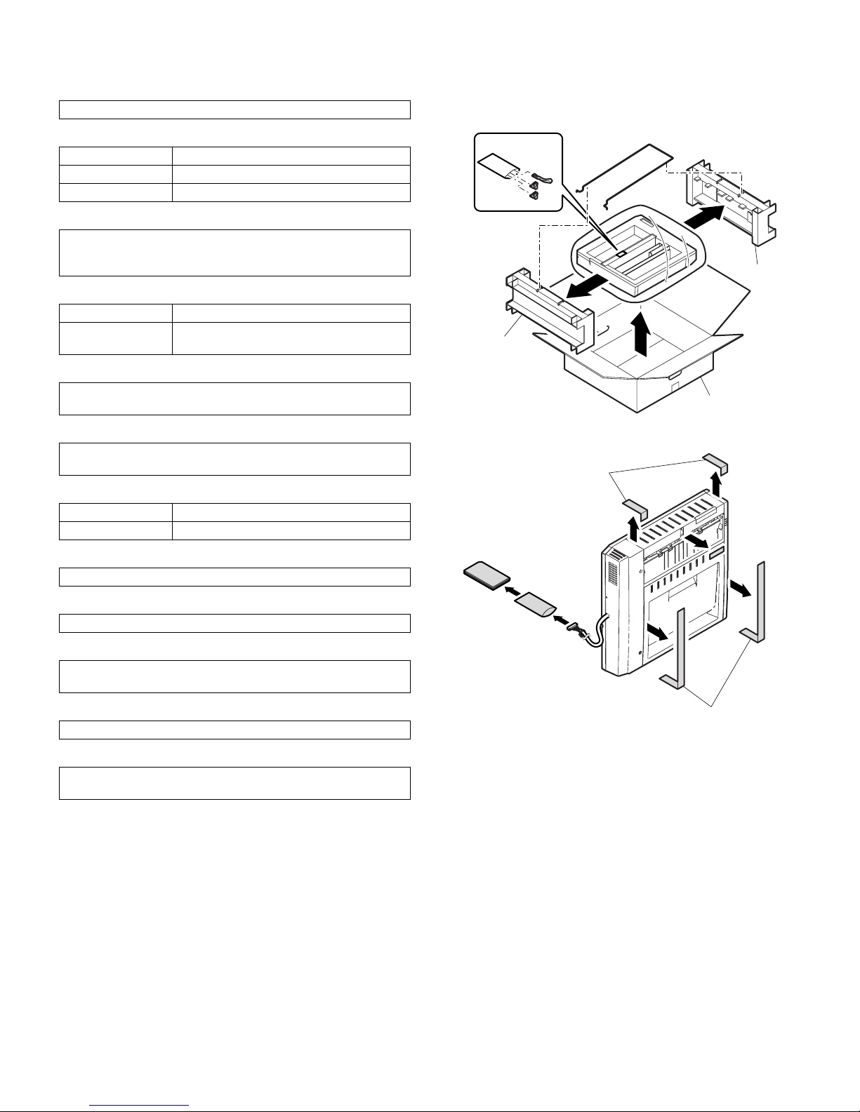
1. UNPACKING
Note: Never put the reverse bypass module down by the dotted sec-
tion on the floor. (The full actuator may be damaged.)
2. Installation
Before installation
• Start installation after checking that the DATA indicator on the operation panel is neither lit nor blinking.
• For installation of AR-RB1, an optional stand (AR-D17/AR-D18/ARD19) must have been installed.
• Ensure that the connecting plate located on the front side of the
optional stand and the connecting plates on the sides (one on the
right side and left side respectively) are securely attached.
Duplex bypass with paper delivery reverse
Straight path Face-up paper delivery
Reverse path Face-down delivery
Duplex bypass Reverse direction and delivery to duplex unit
A3W/A3/B4/A4/A4R/B5/B5R/A5/A6R/Custom
(12
×
18/11 × 17/8.5 × 14/8.5 × 13/8.5 × 11/8.5 × 11R/7.25 × 10.5R/
8.5
× 5.5/EXERA)
Face-up delivery 64 – 105g/m
2
, 106 – 300g/m
2
Face-down delivery/
ADU delivery
64 – 105g/m2, 106 – 200g/m
2
250 sheets
(conditions: A4/letter size recommended, face-down delivery)
58.5mm/s – 550mm/s
(speed based on signal commands from the copier)
Full color 26 sheets/min. (A4 landscape feed)
Monochrome 33 sheets/min. (A4 landscape feed)
5V, 24V supplied by the desk control PWB
6.5 kg
Paper feed, upper and lower turnover motors (stepping motors) and
drive PWB built-in
442.6 (W)
×
126.2 (D) × 431.8 (H) mm
24V: 1A/24W
5V: 0.1A/0.5W
Packing case
Spacer
Spacer
Accessories
Restraining tape
(remove)
Restraining tape (remove)
Page 3
AR-RB1 UNPACKING AND INSTALLATION 2 - 2
Parts included
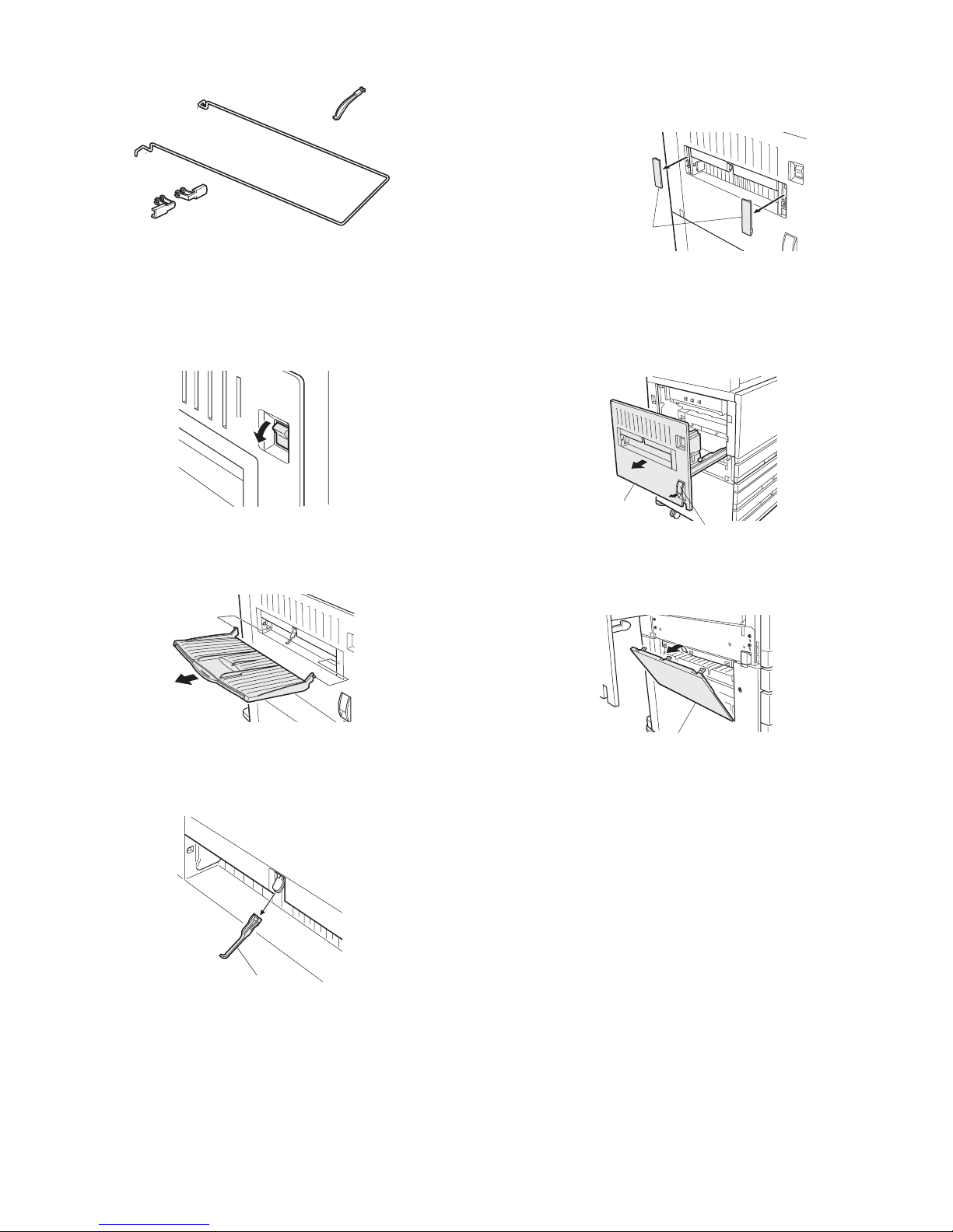
1. Turn off the main switch of the main unit.
1) Turn the main switch located on the left side of the main unit to the
"OFF" position.
2) Then remove the power plug of the main unit from the outlet.
2. Remove the actuator.
1) If the exit tray is installed to the main unit, remove it.
2) While holding the base of the exit actuator of the main unit with one
hand, pull the end of the actuator with the other hand to remove
the actuator.
3. Remove the paper output section covers.
1) Pull the centers of the two paper output section covers on the left
side of the main unit to remove them.
In the case of AR-D17/D18:
1) Pull the lock release lever on the left side of the main unit to pull
out the left cover until it stops.
2) Pull the upper part of the paper input section cover on the left side
of the optional stand to remove the paper input section cover.
Transport guide holder: 2 pcs.
Actuator: 1 pc.
Transport guide: 1 pc.
"OFF"
Exit actuator
Paper output
section covers
Lock release lever
Left cover
Paper input section cover
Page 4
AR-RB1 UNPACKING AND INSTALLATION 2 - 3
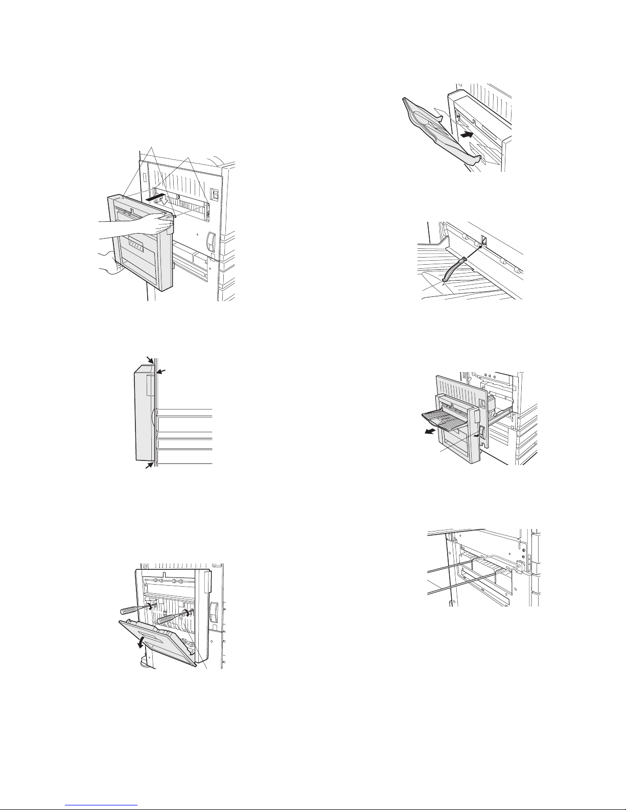
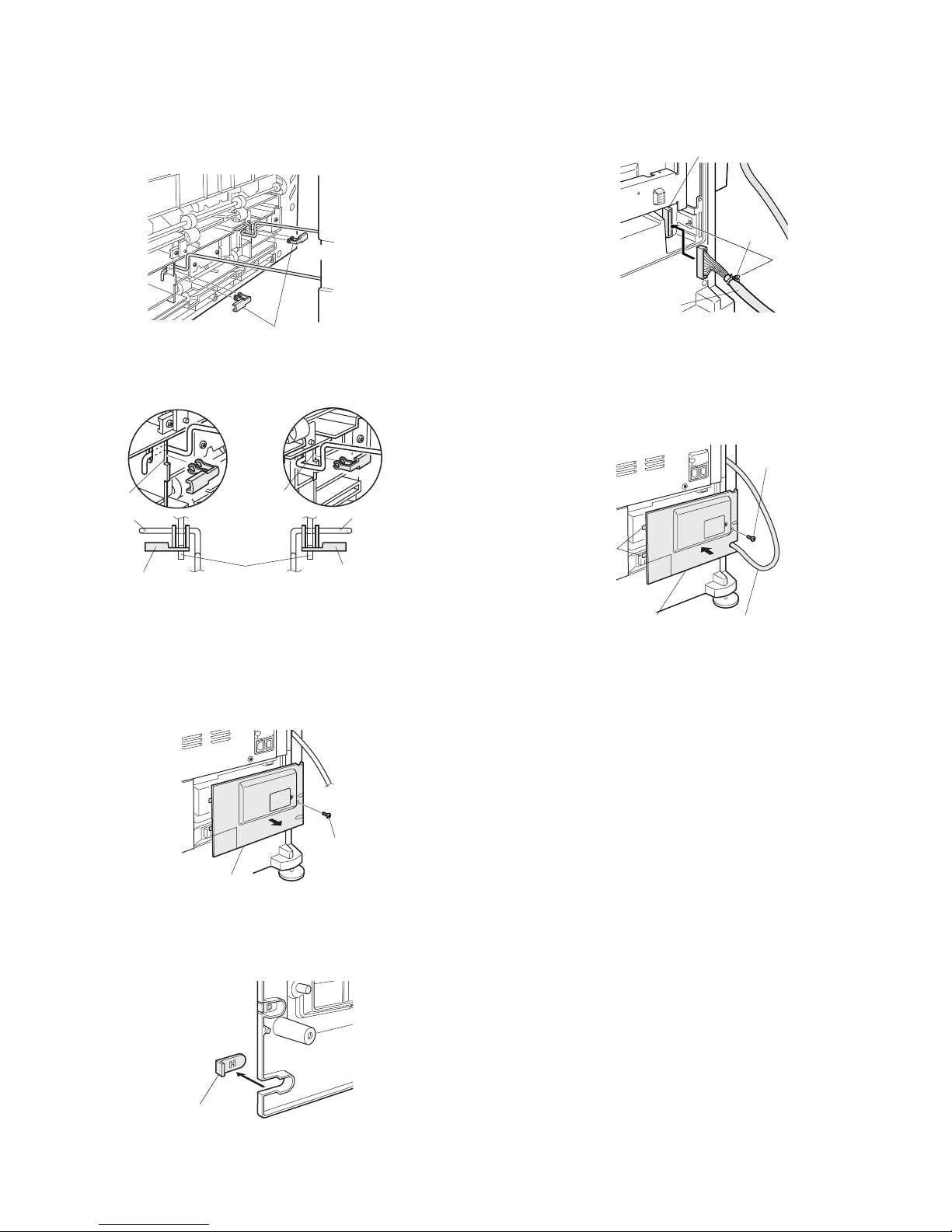
4. Attach the duplex bypass/inverter unit to the main
unit.
1) Close the left cover.
2) Hold the duplex bypass/inverter unit as shown in the illustration
and hang the two positioning bosses at the upper part in the two
positioning holes on the left cover of the main unit.
At this time, check that the two positioning bosses are hung
securely in the two positioning holes of the main unit.
3) Ensure that there is no clearance between the main unit and the
duplex bypass.
5. Secure the duplex bypass/inverter unit.
1) Close the cover of the duplex bypass/inverter unit and tighten the
two built-in screws to secure the duplex bypass to the main unit.
At this time, take care not to damage the transport surface with the
tip of a screwdriver.
2) Close the cover of the duplex bypass/inverter unit and reattach the
exit tray that has been removed in step 2<1> in the raised position
as shown in the illustration.
3) Insert the supplied actuator into the duplex bypass.
6. Attach the transport guide.
1) Pull the lock release lever to pull out the left cover.
2) Insert the transport guide into the paper input section (upper
groove) of the stand.
Positioning bosses
Positioning holes
Transport surface
Actuator
Lock release lever
Transport guide
Page 5
AR-RB1 UNPACKING AND INSTALLATION 2 - 4
3) Attach the transport guide to the duplex bypass/inverter unit and
insert the two transport guide holders into the two transport guides
respectively. At this time, ensure that the transport guide holders
are secured at the notch positions.
4) After checking that the transport guide is aligned with the guide of
the stand, close the left cover of the main unit securely.
7. Connect the harness of the duplex bypass/
inverter unit.
1) Remove the screw from the power supply cover on the rear side of
the optional stand and then remove the power supply cover.
2) Cut out the portion (indicated with H) of the removed power supply
cover shown in the illustration.
3) Connect the relay harness of the duplex bypass/inverter unit to the
connector of the optional stand.
Then, insert the snap band into the mounting hole shown in the
illustration to secure the relay harness.
4) Pass the relay harness through the cut out hole, hang the two
pawls of the power supply cover on the rear cabinet, and attach the
cover with the screw.
Installation of AR-RB1 is now complete.
Transport guide holders
Front side
Rear side
Transport guide holder
Transport guide holder
Transport guide
Transport guide
Front side
Rear side
Notch
Notch
Notches
Power supply cover
Screw
Cut-out portion
Snap band
Relay harness
Connector
Power supply cover
Pawls
Screw
Relay harness
Page 6
AR-RB1 INTERIOR CONSTRUCTION 3 - 1
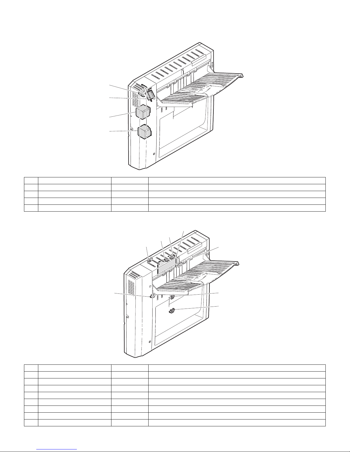
[3] INTERIOR CONSTRUCTION
Motors and solenoid
PWB and sensors
No. Name Abbreviation Function/operation
1 Paper feed motor BIM Transports paper to the paper feed section
2 Gate solenoid BGSOL Switches the gate for straight delivery and reverse delivery
3 Upper turnover motor BRM Paper transport in upper section
4 Lower turnover motor BTM Paper transport in lower section
No. Name Abbreviation Function/operation
1 Door open/closed detector 1 BDD1 Detects open/closed status of upper door
2 Paper delivery sensor BPOD Detects discharged paper
3 Full capacity detection sensor BPFD Detects full capacity status in paper tray
4 BY drive PWB BY drive PWB INVERTER drive and controller
5 Transport sensor 1 BPPD1 Detects transport of paper
6 Reverse section detection sensor BPRD Detects presence of paper in the reverse section
7 Transport sensor 1 BPPD2 Detects transport of paper
8 Door open/closed detector 2 BDD2 Detects open/closed status of lower door
1
2
3
4
1
2
3
4
6
5
7
8
Page 7
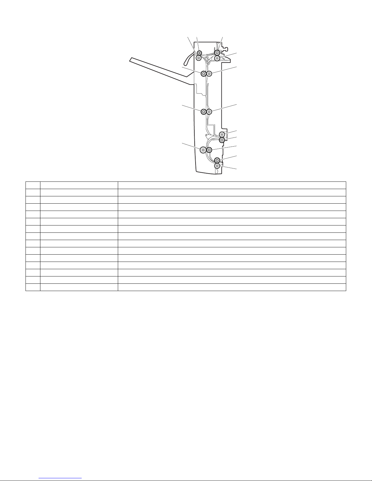
AR-RB1 INTERIOR CONSTRUCTION 3 - 2
Cross-section diagram
No. Name Function/operation
1 Delivery roller Discharges paper to the tray, or transports paper to the finisher.
2 Idle roller Applies a pressure to the delivery roller to transport and discharge paper.
3 Idle roller Applies a pressure to the paper feed roller to transport paper.
4 Paper feed roller Transports paper being transported from the main unit to the paper-out and reverse bypass direction.
5 Upper reverse roller Transports paper to the paper-out and reverse bypass direction.
6 Upper transport roller Transports paper to the paper-out and reverse bypass direction.
7 Lower reverse roller Reverses paper and transports it to ADU.
8 Idle roller Applies a pressure to the lower reverse roller to transport paper.
9 Idle roller Applies a pressure to the lower transport roller to transport paper.
10 Idle roller Applies a pressure to the paper exit roller to transport paper.
11 Paper exit roller Transports paper to ADU.
12 Lower transport roller Transports paper to ADU.
13 Idle roller Applies a pressure to the upper transport roller to transport paper.
14 Idle roller Applies a pressure to the upper reverse roller to transport paper.
1
2
3
4
5
14
13
12
6
7
8
9
10
11
Page 8
AR-RB1 DESCRIPTION OF OPERATION 4 - 1
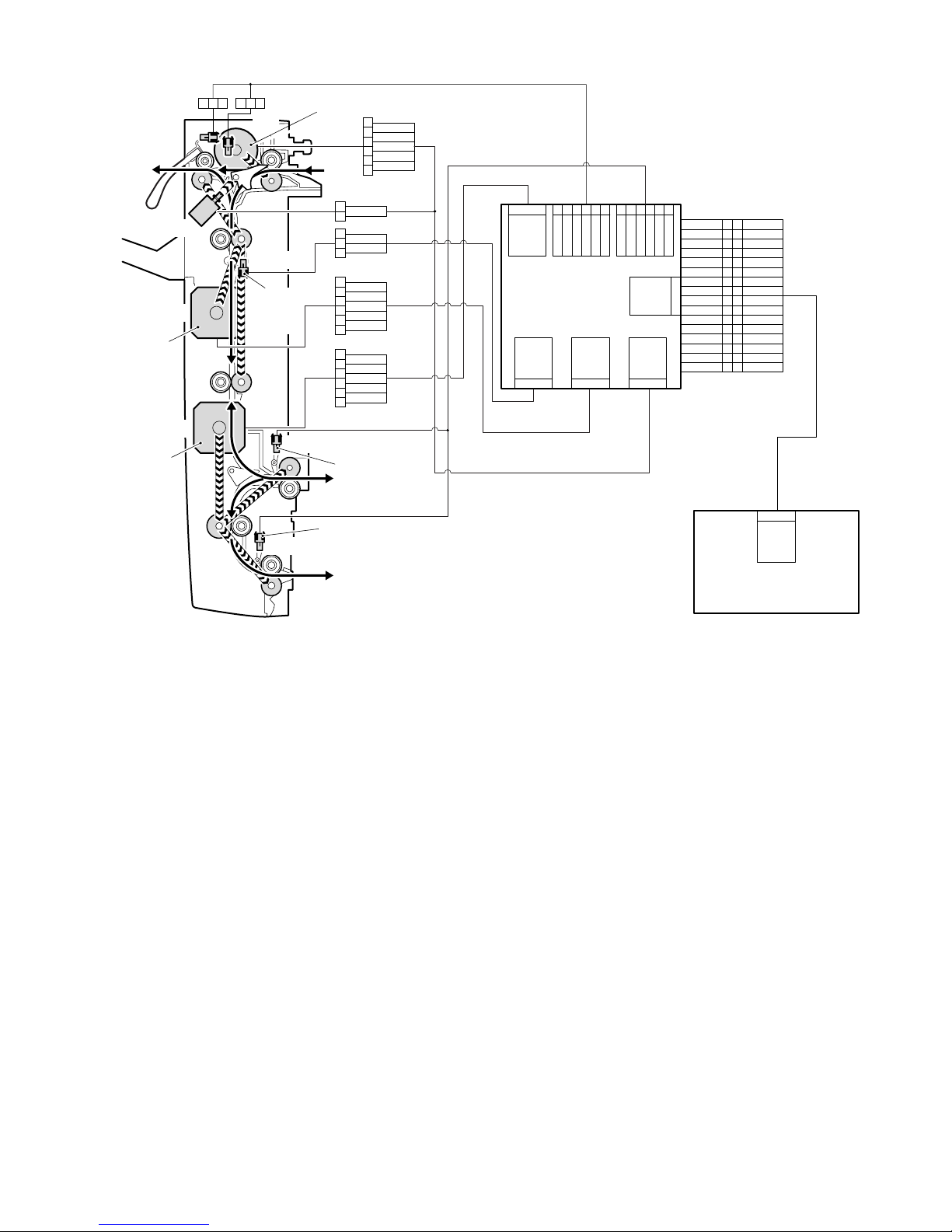
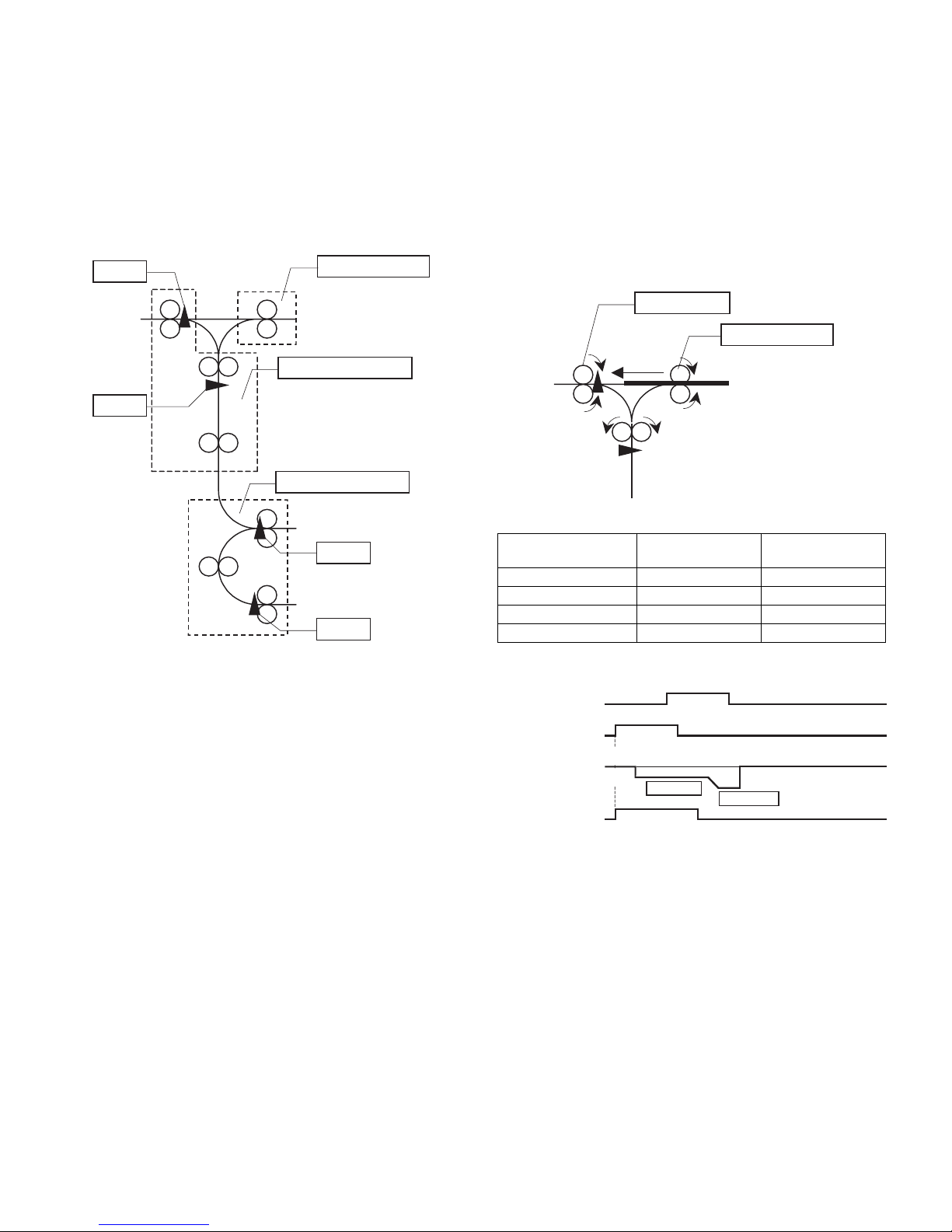
[4] DESCRIPTION OF OPERATION
[Outline of operation]
• The operations include straight delivery, reverse tray delivery, reverse finisher delivery, and ADU delivery (when AR-D19 is installed) operations.
[Sensor and solenoid operation]
BIM (paper in-motor) changes the transport path of the fed paper when BGSOL (gate solenoid) straight delivery is ON and all other operations are
OFF.
• In the case of straight delivery, BPOD (paper discharge detect) detects the passing paper.
• In the case of reverse tray delivery operation, the paper-in motor and the upper reverse motor operates, the paper is fed, and BPPD1 is detected.
Afterward, the upper reverse motor stops, and the paper transport stops.
Next, the upper reverse motor rotates in reverse to transport paper to the direction of paper exit tray.
After BPOD (paper discharge detect) detects the passing paper, it turns off the upper reverse motor.
• In the case of reverse finisher delivery operation, the same as reverse tray delivery operation.
• In the case of ADU operation, the lower reverse motor operates, and the paper being transported to the reverse roller is detected by BPRD.
After being detected, the lower reverse motor stops, then it rotates in reverse, and the paper is transported to ADU.
After BPPD2 detects the passing paper, it turns off the motor.
27
29
+24V
+5V
31
GND
17
19
BRM/A
BRM/B
21
23
BPOWD
BTMA
25
BTMB
7
9
/BDD2
BFM
11
13
BIMA
BIMB
15
Vref1
1
3
/BPOD
/BPPD1
5
/BPRD
28
30
+24V
GND
32
/BYSET
18
20
BRMA
BRMB
22
24
BTM/A
BTM/B
26
+24V
8
10
BGSOL
BIM/A
12
14
BIM/B
BPOWD2
16
Vref2
2
4
/BPFD
/BPPD2
6
/BDD1
9
GND87/BPOD
+5V65GND
/BPFD4+5V6GND54/BPRD
+5V32GND
/BPPD21+5V
CN-H (6pin)
CN-E (3pin) CN-D (6pin) CN-C (8pin)
CN-G (9pin) CN-F (10pin)
CN-A (32pin)
BY drive PWB
Desk control PWB
CN-G (32pin)
1
2
5
3
4
6
BTM/B
+24V
+24V
BTMB
BTMA
BTM/A
1
2
5
3
4
6
BIM/B
+24V
+24V
BIMB
BIMA
BIM/A
1
2
5
3
4
6
BRM/B
+24V
+24V
BRMB
BRMA
BRM/A
1
2
3
+5V
/BPPD1
GND
1
23123
1
2
+24V
/BGSOL
ADU
BRM
BPPD2
BPPD1
BGSOL
BPRD
BTM
BIM
BPODBPFD
Paper feed motor
Upper turnover
motor
Transport of
paper
detected
Lower turnover
motor
Presence of
paper in reverse
section detected
Transport of
paper detected
Page 9
AR-RB1 DESCRIPTION OF OPERATION 4 - 2
(1) Initial operation
When the power to the copier is turned on, in order to confirm whether
or not there is paper in the transport path, the paper input motor, upper
turnover motor and lower turnover motor revolve for a predetermined
time.
Even after the predetermined time has passed, if all the transport sensors are OFF and it is determined that there is no paper in the transport path, if within a given period of time at least one transport sensor
turned ON, it is interpreted as paper being present in the transport path
(paper jam).
(2) Straight delivery operation
In this operation, the paper discharged from the copier is sent directly
to the paper exit tray or transported to the finisher.
When the paper input motor and upper turnover motor revolve, the
paper input roller and delivery roller rotate in the directions as shown in
the figure below to discharge the paper.
If the paper is delivered to the finisher, it is transported at the same
speed at which it is discharged from the copier.
As the paper is discharged to the paper exit tray, when the trailing
edge reaches a point 50mm from the delivery roller on the copier side,
the speed of the delivery roller increases, and the paper is discharged
to the tray.
Unit: mm/s
Sensor input, motor output, solenoid output timing is as below.
Paper input motor
BPOD
BPPD1
BPRD
BPPD2
Upper turnover motor
Lower turnover motor
Paper kind
Copier process
speed
RB1 tray delivery
speed
Thick paper 2 58.5 58.5
Envelope 117 117
OHP (priority: quality) 58.5 120
OHP (priority: speed) 117 160
Paper input roller
Delivery roller
BPOD
(Paper exit sensor)
BIM
(Paper-in motor)
BRM
(Upper reverse motor)
Process speed
BGSOL
(Gate solenoid)
Delivery speed
(Direction of
paper-in)
(Direction of
paper-out)
Page 10
AR-RB1 DESCRIPTION OF OPERATION 4 - 3
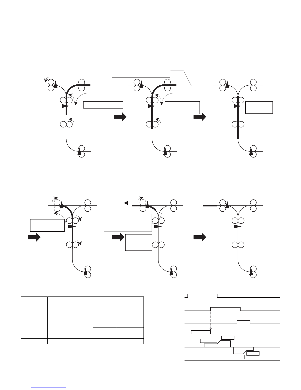
(3) Reverse tray delivery operation
A. When paper length is 249mm or less (letter size or less)
(Both the paper input motor and upper turnover motor operate)
The relation between the process speed and the transport speed in
RB1 is as follow.
Unit: mm/s
Sensor input, motor output, solenoid output timing is as below.
Processing speed
The paper input motor and
upper turnover motor are
caused to turn in time with the
copier processing speed, thus
transporting the paper.
When the trailing edge of the paper
reaches a point 13mm from the copier
POD off, the transport speed in RB1
is accelerated.
Trailing edge of paper reaches
point 13mm from POD off
Transport speed
(high speed)
Transport speed
(high speed)
Transport
speed
(low speed)
When the trailing edge of
the paper reaches the upper
reverse stop point, the
motor stops.
Motor stop
(paper stop)
Motor stop
(discharge complete)
The upper turnover motor is
caused to revolve in the paper
delivery direction, and the paper
is discharged.
When the trailing edge of the paper
reaches a point 50mm before the
delivery roller, the transport speed
decreases.
Trailing edge of paper
reaches point 50mm
before delivery roller
After the trailing edge of the paper
passes the delivery roller, the
upper turnover motor stops.
Paper kind
Copier
process
speed
RB1 transport
speed
(high speed)
Paper size
RB1 transport
speed
(low speed)
Normal paper 117/140 550 A3/A3W
/EXTRA
450
A4R 430
A4/B5/B5R 400
B4/A5 320
Thick paper 1 58.5 195 All size 195
POD
(Paper exit sensor)
BPPD1
(Transport sensor 1)
BPOD
(Paper-out sensor)
BIM
(Paper-in motor)
BRM
(Upper reverse motor)
BGSOL
(Gate solenoid)
(Direction of paper-out)
(Direction of paper-in)
Process speed
High speed
High speed
Low speed
Page 11
AR-RB1 DESCRIPTION OF OPERATION 4 - 4
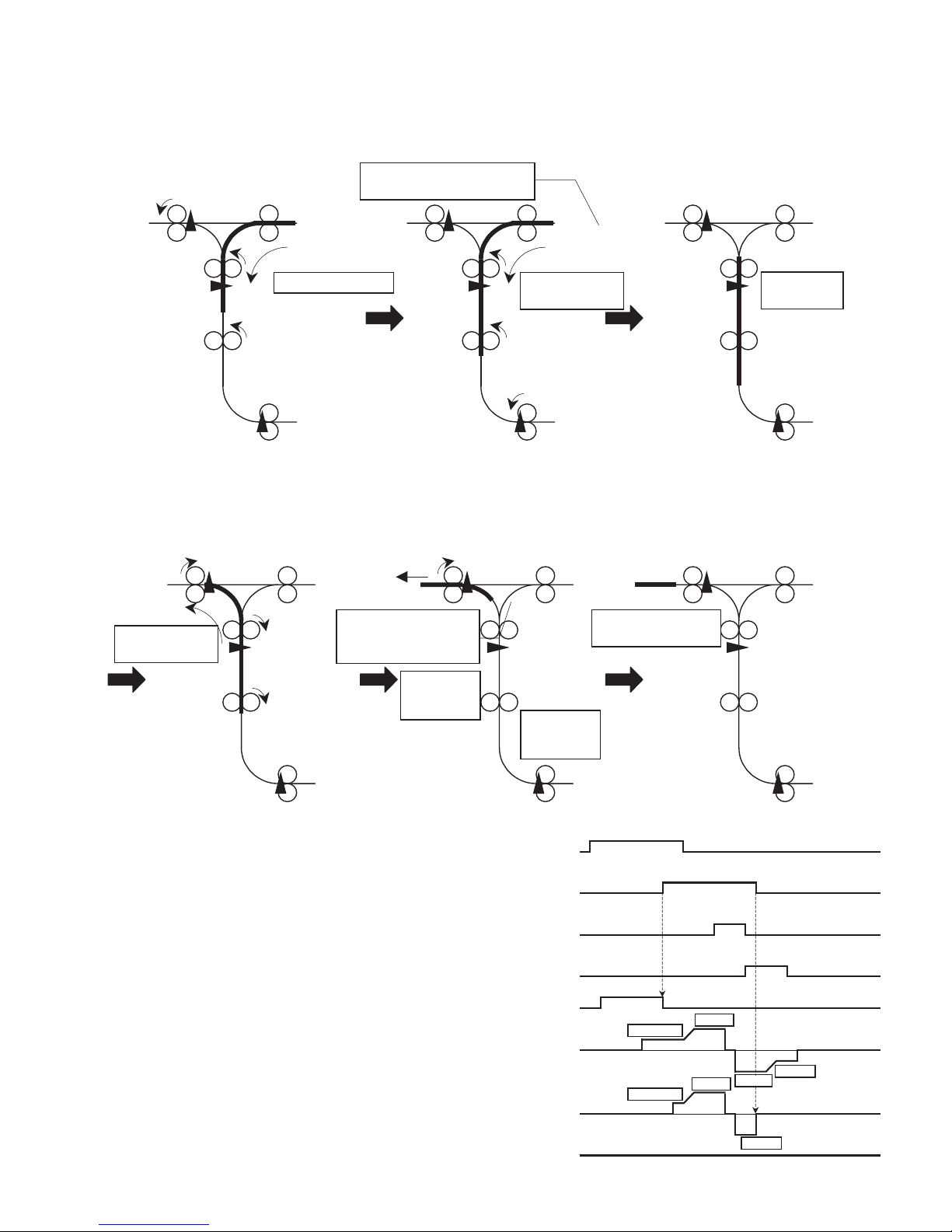
B. When the paper length is 250mm or more (B5R or more)
(The paper input motor, upper turnover motor and lower turnover motor all operate.)
As for the relation between the process speed and the transport speed
in RB1, refer to the table (3)-A.
Sensor input, motor output, solenoid output timing is as below.
Processing speed
The paper input motor and
upper turnover motor are
caused to turn in time with the
copier processing speed, thus
transporting the paper.
When the trailing edge of the paper
reaches a point 13mm from the copier
POD off, the transport speed in RB1
is accelerated.
Trailing edge of paper reaches
point 13mm from POD off
Transport speed
(high speed)
Transport speed
(high speed)
When the trailing edge of the
paper reaches the upper reverse
stop point, the upper turnover
motor and the lower turnover
motor stop.
Motor stop
(paper stop)
The upper turnover motor and the
lower turnover motor are caused to
revolve in the paper delivery direction,
and the paper is discharged.
The lower reverse motor stops at
BPPD1 off, when the trailing edge of the
paper reaches a point 50mm before the
delivery roller, the transport speed
decreases.
Trailing edge of paper
reaches point 50mm
before delivery roller
After the trailing edge of the paper
passes the delivery roller, the
upper turnover motor stops.
Transport
speed
(low speed)
Lower
turnover
motor stop
Motor stop
(discharge complete)
POD
(Paper exit
sensor)
BPPD1
(Transport
sensor 1)
BPRD
(Reverse section
detection sensor)
BPOD
(Paper-out sensor)
BIM
(Paper-in motor)
BRM
(Upper reverse
motor)
(Direction of paper-in)
(Direction of paper-out)
(Direction of paper-in)
(Direction of paper-out)
BTM
(Lower reverse
motor)
BGSOL
(Gate solenoid)
Process speed
Process speed
High speed
High speed
High speed
High speed
Low speed
Page 12

AR-RB1 DESCRIPTION OF OPERATION 4 - 5
(4) Reverse finisher delivery operation
A. When paper length is 249mm or less (letter size or less)
(Both the paper input motor and upper turnover motor operate)
Table showing relation between the processing speed and the transport speed in RB1
Unit: mm/s
Sensor input, motor output, solenoid output timing is as below.
B. When the paper length is 250mm or more
(B5R or more)
(The paper input motor, upper turnover motor and lower turnover motor
all operate.)
Other than this, it is controlled by the same conditions as for letter-size
or less.
The paper input motor and
upper turnover motor are
caused to turn in time with the
copier processing speed, thus
transporting the paper.
Processing speed
When the trailing edge of the paper
reaches a point 13mm from the copier
POD off, the transport speed in RB1
is accelerated.
Trailing edge of paper reaches
point 13mm from POD off
When the trailing edge of
the paper reaches the upper
reverse stop point, the
motor stops.
Transport speed
(high speed)
Motor stop
(paper stop)
The upper turnover motor is
caused to revolve in the paper
delivery direction, and the paper
is discharged.
Just before the leading edge of the
paper reaches the first roller of the
finisher, the transport speed decreases.
After the trailing edge of the paper
passes the delivery roller, the
upper turnover motor stops.
Transport speed
(high speed)
Motor stop
(discharge
complete)
Finisher
No. 1 roller
Transport
speed
(low speed)
Copier processing
speed
RB1 transport speed
(high)
RB1 transport speed
(Finisher speed)
58.5 195 195
117 550 450
140 550 550
POD
(Paper exit sensor)
BPPD1
(Transport sensor 1)
BPOD
(Paper-out sensor)
BIM
(Paper-in motor)
BRM
(Upper reverse
motor)
(Direction of paper-in)
(Direction of paper-out)
BGSOL
(Gate solenoid)
Process speed
Finisher speed
High speed
High speed
Page 13

AR-RB1 DESCRIPTION OF OPERATION 4 - 6
(5) ADU delivery operation (AR-D19 the installed)
Table showing relation between the processing speed and the transport speed in RB1
Unit: mm/s
Sensor input, motor output, solenoid output timing is as below.
Processing speed
The paper input motor and
upper turnover motor are
caused to turn in time with the
copier processing speed, thus
transporting the paper.
When the trailing edge of the paper
reaches a point 13mm from the copier
POD off, the transport speed in RB1
is accelerated.
Trailing edge of paper reaches
point 13mm from POD off
Transport speed
(high speed)
Transport speed
(high speed)
Transport speed
(high speed)
Lower reverse
stop point
When the trailing edge of the
paper reaches the lower reverse
stop point, the motor stops.
The lower turnover motor is caused to
revolve in the direction of the ADU,
discharging the paper.
When the trailing edge of the paper
passes the delivery roller, the
motor stops.
Copier processing speed RB1 transport speed (high)
58.5 195
117 550
140 550
POD
(Paper exit sensor)
BPPD1
(Transport sensor 1)
BPRD
(Reverse section
detection sensor)
BPPD2
(Transport sensor 2)
BIM
(Paper-in motor)
(Direction of paper-in)
(Direction of paper-out)
(Direction of paper-in)
(Direction of paper-out)
BRM
(Upper reverse
motor)
BTM
(Lower reverse
motor)
BGSOL
(Gate solenoid)
Process speed
High speed
High speed
High speed
Page 14

AR-RB1 DISASSEMBLY, ASSEMBLY AND MAINTENANCE 5 - 1
[5] DISASSEMBLY, ASSEMBLY AND MAINTENANCE
1. Maintenance system table
✕ : Check (for cleaning, replacement or adjustment as necessary) ❍ : Clean ▲ : Replace ∆
: Adjust ✩ : Lubricate ❏ : Relocate
Unit name No. Part name
When
requested
50K 100K 150K 200K 250K 300K 350K 400K Remarks
Transport
section
1 Transport rollers ❍ ❍❍❍❍❍❍❍❍
2Rollers ❍ ❍❍❍❍❍❍❍❍
3 Transport paper guides ❍ ❍❍❍❍❍❍❍❍
Drive unit 4 Gears ✕ ✕✕✕✕(designated spots)
5Belts ✕✕
Others 6 Sensors ✕ ✕✕✕✕
7 Discharge brushes ✕ ✕✕✕✕
NOTE: When to replace: Check the counter value on the respective paper feed entrances.
Paper feed rollers/torque limiter parts: 100K or 2 years.
1
1
2
2
2
1
1
3
3
4
4
5
2
2
2
6
7
6
6
5
Page 15

AR-RB1 DISASSEMBLY, ASSEMBLY AND MAINTENANCE 5 - 2
2. Maintenance
A. Transport section
✕ : Check (for cleaning, replacement or adjustment as necessary) ❍ : Clean ▲ : Replace ∆
: Adjust ✩ : Lubricate ❏ : Relocate
(1) All transport rollers
a. Copier
1) Detach the connector and remove the screws. Remove (A) the
bypass drive PWB.
<1> Delivery roller
1) Open (A) the left door.
2) Open (B) the upper open/close unit.
3) Remove the screws, and remove (C) the rear casing.
4) Remove the screws, and remove (D) the front casing.
5) Remove the E-rings, gears and bearings, and take out (E) the
delivery roller.
<2> Paper input roller
1) Remove the rear and front casings.
2) Detach the connector, remove the screws, and take out (A) the
paper input motor unit.
3) Remove the E-rings, gears and bearings, and take out (B) the
paper input roller.
Unit name No. Part name
When
requested
50K 100K 150K 200K 250K 300K 350K 400K Remarks
Transport
section
1 Transport rollers
❍ ❍❍❍❍❍❍❍❍
2Rollers
❍ ❍❍❍❍❍❍❍❍
3 Transport paper guides
❍ ❍❍❍❍❍❍❍❍
A
A
B
D
C
E
A
B
Page 16

AR-RB1 DISASSEMBLY, ASSEMBLY AND MAINTENANCE 5 - 3
<3> Upper turnover roller
1) Remove the rear and front casings.
2) Remove the bypass drive PWB.
3) Remove the E-ring, Mylar, belt, pulley, gears, pins and bearings,
and take out (B) the upper turnover roller.
<4>Lower turnover roller
1) Remove the rear and front casings.
2) Remove (A) the E-ring, and slide the bearing over.
3) Remove the belt, and take out the lower turnover roller unit.
4) Remove the E-rings, pulley, pin, Mylar and bearings from (B) the
lower turnover roller.
<5> Upper transport roller
1) Remove the rear and front casings.
2) Remove the E-rings, belt, pulley, pin and bearings.
3) Remove (A) the upper transport roller.
<6> Lower transport roller
1) Remove the rear and front casings.
2) Remove (A) the E-ring, belt and pulley.
3) Remove (B) the E-rings, slide the bearing over, and take out the
lower transport roller unit.
4) Remove the pin and bearing from (C) the lower transport roller.
<7> Delivery roller
1) Remove the rear and front casings.
2) Remove the screws, remove (A), and take out (B) the left door unit.
3) Remove the E-rings, belt, pulley, pin and bearings. Take out (C)
the delivery roller.
B
A
A
B
A
A
B
B
C
A
B
C
Page 17

AR-RB1 DISASSEMBLY, ASSEMBLY AND MAINTENANCE 5 - 4
(2) Rollers
a. Paper delivery cabinet
1) Remove the delivery roller.
2) Remove (A) the screw, remove (B) the ADU open/closed sensor
mounting plate, and detach the connector.
3) Remove the screws, and take out (C) the paper delivery cabinet
unit.
(3) Transport paper guides
B. Drive section
✕ : Check (for cleaning, replacement or adjustment as necessary) ❍ : Clean ▲ : Replace ∆ : Adjust ✩ : Lubricate ❏ : Relocate
(1) Gears
a. Copier
1) Remove the rear casing. 2) Remove the front gears.
A
B
C
Unit name No. Part name
When
requested
50K 100K 150K 200K 250K 300K 350K 400K Remarks
Drive unit 1 Gears ✕ ✕✕✕✕(designated spots)
2Belts ✕✕
Page 18

AR-RB1 DISASSEMBLY, ASSEMBLY AND MAINTENANCE 5 - 5
(2) Belts
a. Copier
1) Remove the rear casing.
C. Others
✕ : Check (for cleaning, replacement or adjustment as necessary) ❍ : Clean ▲ : Replace∆ : Adjust ✩ : Lubricate ❏ : Relocate
(1) Sensors
a. Copier
1) Remove the screw, and remove the sensor holder.
2) Remove the screws, and remove the sensor covers.
b. Upper open/closed unit
1) Open the upper open/closed unit, remove the E-ring and bearing,
and take out (A) the gate unit.
2) Remove the screw, and remove (B) the upper cabinet.
Unit name No. Part name
When
requested
50K 100K 150K 200K 250K 300K 350K 400K Remarks
Others 1 Sensors ✕ ✕✕✕✕
2 Discharge brushes ✕ ✕✕✕✕
A
B
Page 19

AR-RB1 DISASSEMBLY, ASSEMBLY AND MAINTENANCE 5 - 6
c. Paper delivery cabinet unit
1) Remove the rear casing.
2) Open the left door unit, remove the screw, and remove (A) the
ADU open/closed sensor mounting plate.
(2) Discharge brushes
D. Principal parts
(1) Paper input motor
1) Remove the rear casing.
2) Detach the connector, remove the screws, and remove (A) the
paper input motor.
(2) Upper reverse transport motor/Lower reverse
transport motor
1) Remove the rear casing.
2) Detach the harness from the clamp.
3) Remove the connector, remove the screws, and take out the upper
reverse transport motor unit/the lower reverse transport motor unit.
4) Remove the screws, and remove (A) the upper reverse transport
motor/(B) the lower reverse transport motor.
(3) SF pressure release solenoid
1) Remove the rear and front casings.
2) Remove the delivery roller, and take out the paper delivery cabinet
unit.
3) Remove the paper input motor unit.
4) Detach the connector, remove the screws and spring, and remove
(A) the SF pressure release solenoid.
(4) Bypass drive PWB
1) Detach the connector, remove the screws, and take out (A) the
bypass drive PWB.
A
B
C
A
A
B
A
A
Page 20

AR-RB1 ELECTRICAL SECTION 6 - 1
BIMB
/BDD1
N.C.
/BPPD2
BRM/A
Vref1
BIM/A
/BPRD
BFM
/BPPD1
BRMA
/BDD2
/BPOD
BIM/B
BIMA
Vref2
/BPFD
BPOWD2
N.C.
BGSOL
10
17
18
12
7
1
16914
19
20
3
11
8
5152134
6
XADRP-40V
32
39
21
GND
252926
BRMB31BPOWD
33
30
BTMA
40
38
35
27
BTM/B
36
BTM/A34+24V2824BTMB
23
BRM/B
22
37
12
19
1
596
111310
20
18
15716
14
8
432
17
36
233127
24
38
322930
3437333935
264028
25
22
21
+24V
+24V
+5V
GND
/BYSET
F.G.
F.G.
BIM/A
/BFM
BIMB
BRMA
/BPOD
BIMA
/BPFD
/BPPD2
/BPRD
/BPPD1
/BDD2
BIM/B
/BDD1
/BGSOL
BRM/A
BRM/B
BRMB
8
5
2
10
426
4
2
3
2
371
8
4
6
1
+24V 1
CN-B
+24V 2
+24V 5
+24V 7
CN-C
+24V 2
+24V 5
+5V 1
3GND
CN-E
1+5V35
GND
+5V
6
8
GND
+5V 9
GND
CN-F
+5V 1
3GND
+5V 4
6GND
+5V 7
9GND
CN-G
CN-D
CN-H
/BFM2
+24V1
BFM
4
+24V
BIM
+24V
BIM/A
352
BIMB
BIM/B
BIMA
1
6
45136
2
2 /BGSOL
+24V1
BGSOL
BRM
312 /BPPD1
+5V
GND
BPPD1
132 /BPPD2
+5V
GND
BPPD2
132 /BPRD
+5V
GND
BPRD
/BDD2
1 GND
3 +5V
2 BDD2
BDD1
+5V
GND1
3
2 /BDD1
BPFD
1
3 +5V
2 /BPFD
GND
BPOD
1
3 +5V
2 /BPOD
GND
AR-RB1
B2B-PH-K-S
B8B-PH-K-S
B6B-PH-K-R
B3B-PH-K-S
B10B-PH-K-S
B9B-PH-K-S
B6B-PH-K-S
BY DRIVE PWB
4
1BTM/B
BTMB
+24V
2
3
BTM/A
+24V6BTMA
5
BTM
29
15
4
BIMA
Vref2
Vref1
+24V
BRM/A
25
14
7
BPOWD222BRMA
GND
28
16
+5V
20
173219
8
12
2
5
BIM/A10
26
BTMB
30
/BPPD1
11
23
CN-A
BGSOL
BTM/B
/BDD2
+24V
18
BRMB
/BPPD2
BPOWD
/BPRD
/BPOD
/BDD1
+24V
BFM
/BPFD
13
1
24
GND31
6
BIM/B
BTMA
BIMB
BTM/A
27
S32B-PHDSS213
BRM/B
9
GND(/BYSET)
N.C.
EXIN1
EXIN2
GND
GND
SMP-06V-BC SMR-06V-B
AR-D17/18/19
[6] ELECTRICAL SECTION
(1) Actual wiring chart
Page 21

AR-RB1 ELECTRICAL SECTION 6 - 2
(2) Signal list
(3) Block diagram
SIGNAL NAME NAME Function/Operation
BDD Door open detection 1 Detects upper door open.
BDD2 Door open detection 2 Detects left door open.
BGSOL Gate solenoid Switches straight or reverse paper exit.
BIM Paper entry motor Transports paper in the paper entry section.
BPFD Full sensor Detects paper full on the tray.
BPOD Paper exit sensor Detects paper exit.
BPPD1 Transport sensor 1 Detects paper transport.
BPPD2 Transport sensor 2 Detects paper transport.
BPRD Reverse section sensor Detects paper presence in the reverse section.
BRM Upper reverse motor Transports paper in the upper section.
BTM Lower reverse motor Transports paper in the lower section.
/BPOD1
/BPFD1
/BPPD1
/BPPD2
/BPRD
/BDD1
/BDD2
/BYPSET
+5V
+24V
BPFD
Paper delivery sensor
Transport sensor 1
Full capacity detection sensor
BDD2
BPOD
+5V
+5V
BPPD2
Door open/closed detection sensor 1
+5V
+5V
Door open/closed detection sensor 2
Transport motor
BPPD1
BDD1
+5V
Reverse section detection sensor+5V
BPRD
+5V
Transport sensor 2
BGSOL
Gate solenoid
+24V
(MTD1361)
Turnover motor
Paper input motor
Chopping circuit
+24V
BIM
BRM
AR-RB1
6
4
GND
+24V
+24V
BFM
Cool down fan motor
(MTD1361)
Chopping circuit
Transistor
Transistor
BTM +24V
(MTD1361)
Chopping circuit
GND
6
4
4
AR-D17/18/19
Page 22

AR-RB1 ELECTRICAL SECTION 6 - 3
CNA-30
GND
CNA-28
+24V
C2
473Z/16V
Q102
RT1N141C
C24
223Z/50V
C23
47uF/35V
+
D102
R19
6.8KJ
R1 6.8KJ
C8 222K/50V
C4
332K/50V
CNB-1
+24V
C26
47uF/35V
+
C3
332K/50V
R9
1KJ
C5
473Z/16V
R10
1KJ
CNA-17
BRM/A
Q101
RT1N141C
R30
1kJ
CNA-15
Vref1
TR1
2SD1264P
ZD1
HZ27-3
C25
473Z/16V
CNA-16
Vref2
R32
2.4kJ
CNA-29
+5V
CNA-27
+24V
CNA-31
GND
CNA-32
/BYSET
BRMA
CNH-4
BRM/A
CNH-6
BRMB
CNH-3
BRM/B
CNH-1
CNC-2
+24V
CNC-5
+24V
CNC-7
+24V
CND-2
+24V
CND-5
+24V
CNE-1
+5V
CNF-1
+5V
CNF-4
+5V
CNF-7
+5V
CNG-1
+5V
CNG-4
+5V
CNG-7
+5V
CNE-3
GND
CNF-3
GND
CNF-6
GND
CNF-9
GND
CNG-3
GND
CNG-9
GND
CNB-2
/BFM
CNC-8
/BGSOL
CNA-8
BGSOL
CNA-1
/BPOD
CNA-2
/BPFD
CNA-3
/BPPD1
CNA-4
/BPPD2
CNA-5
/BPRD
CNA-6
/BDD1
CNA-7
/BDD2
CNG-8
/BPOD
CNG-5
/BPFD
CNE-2
/BPPD1
CNF-2
/BPPD2
CNF-5
/BPRD
CNG-2
/BDD1
CNF-8
/BDD2
C22
223Z/50V
C1 222K/50V
CNA-26
+24V
CNG-6
GND
CNA-14
BPOWD2
Q103
RT1N141C
R2
430J
R28
360J
R3
6.8KJ
C17
223Z/50V
R40
6.8KJ
C19
473Z/16V
R47
360J
BTMA
CND-4
D105
R50
0.47J(1W)
R42
0.47J(1W)
C18
332K/50V
R44
1KJ
R49
6.8KJ
R27 6.8KJ
C14 222K/50V
C21 222K/50V
CNA-21
BPOWD
CNA-22
BTM/A
CNA-23
BTMA
CNA-25
BTMB
CNA-24
BTM/B
BTM/A
CND-6
BTMB
CND-3
BTM/B
CND-1
Q104
RT1N141C
R46
2.4kJ
R35
CNA-20
BRMB
CNA-18
BRMA
CNA-19
BRM/B
R34R38
R48
R39
R51
R45
4.7KJ
R41
4.7KJ
R43
4.7KJ
R37
4.7KJ
R12 R8R7R11
R14
0.47J(1W)
R6
0.47J(1W)
R36
1KJ
C15
332K/50V
CNH-2
+24V
CNH-5
+24V
BIMB
CNC-3
BIM/A
CNC-6
BIMA
CNC-4
R21 6.8KJ
R22
6.8KJ
C10 222K/50V
C11 222K/50V
C7
332K/50V
R16
1KJ
R5
0.47J(1W)
C6
332K/50V
BIM/B
CNC-1
R4
0.47J(1W)
D110
R13
1KJ
R25R23R26R24
CNA-10
BIM/A
CNA-11
BIMA
CNA-12
BIM/B
C16
223Z/50V
CNA-13
BIMB
R31
360J
R15
430J
R17
6.8KJ
R29
1kJ
R33
2.4kJ
CNA-9
BFM
CP3
CP2
CP1
IC101
MTD1361F
IC3
TD62003AP
D104
D107
D109D112D111
D106
D101
C20
47uF/35V
+
IC2
MTD1361
C13
47uF/35V
+
D103
R18
300J
IC1
MTD1361
C12
47uF/35V
+
D108
R20
6.8KJ
C9
473Z/16V
+5V
+24V
+24V
+24V
+5V
+24V
+5V
+5V
+5V
+5V
+5V
+5V
+5V
+5V
+5V
+24V
+5V
+5V
B
1
E2C
3
B
1
E2C
3
B
1
E2C
3
B
1
E2C
3
NC2NC5Rs A3Vs A25Vs B18Rs B12Vref A24Vref B
19
NC6NC
7
Vmm
22PG15NC8NC9NC10
CR A
23NC13NC21
PG
28
IN /A26IN A27IN /B17IN B
16
CR B
20
OUT A
4
OUT /A
1
OUT B
11
OUT /B
14
COM
9
I11I22I33I44I55I66I77GND
8
O116O215O314O413O512O611O7
10
NC11NC12Rs A9Vs A4Vs B24Rs B19Vref A3Vref B
25
NC14NC
15
Vmm
1PG7PG21LG27NC16
CR A
2NC17PG13
IN /A5IN A6IN /B23IN B
22
CR B
26
OUT A
10
OUT /A
8
OUT B
18
OUT /B
20
NC11NC12Rs A9Vs A4Vs B24Rs B19Vref A3Vref B
25
NC14NC
15
Vmm
1PG7PG21LG27NC16
CR A
2NC17PG13
IN /A5IN A6IN /B23IN B
22
CR B
26
OUT A
10
OUT /A
8
OUT B
18
OUT /B
20
+5V
GND
12345
6
(JST:B10B-PH-K-S)
BIM/A
16
22
19
/BPFD
9
/BPRD
26
3
BRMA
BPOWD2
BRM/A
21
/BDD1
CN-A
17811
BPOWD
5
10BFM
25
2
24
18
Vref2
BGSOL
BIMA
/BPPD2
15
/BPOD
7
20 BRMB
4/BPPD1
+24V
1
23
27 28
29 30
BRM/B /BPOD
DESK
BODY
6
12
13 14BIMB
8
BPFD
Vref1
+5V
7
/BFM
(JST:B2B-PH-K-S)
+24V
CN-B
1
BFM
2
/BDD2
+24V
+5V
5
BIM/B1
GND
CN-C
6
3
/BGSOL
BDD2
(JST:B8B-PH-K-S)
4
2
(JST:B6B-PH-K-S)
CN-D
+24V
GND
+24V
+24V
BTMA
BTM/B5BTM/A
1
BTMB
6
3
+24V
BTM
4
2
M1FL20U × 4
NOTE 1: Assumed 1/16 W for a resistance that does not register a rated loss.
Upper turnover motor
100% : I=0.63A
70% : I=0.45A
40% : I=0.30A
POWD100%:I=0.54A
POWD70%:I=0.40A
POWD40%:I=0.28A
/BYSETGND
DESK
BODY
/BDD2
CN-F
+5V
GND
/BPFD
9
+5V
/BDD1
GND
BIMB
+24V
+24V7BIMA
BIM
8
BIM/A
BGSOL
/BPRD
+5V
5
1
GND
6
3
BPRD
(JST:B9B-PH-K-S)
428
7
+5V
GND
CN-A
CN-G
CN-C CN-B
CN-F
CN-D
BPOD
BDD1
BPPD2
4.7k X 2
CN-E
BPPD1
GND
/BPPD1
(JST:S3B-PH-K-S)
+5V
/BPPD2
CN-E
312
9
Lower turnover motor
I=0.53A
M1FL20U × 4
POWD : I=0.47A
4.7k X 4
4.7k X 4
(JST:S32B-PHDSS)
31 32
BTM/A
BTMA BTM/B
BTMB
CN-G
(JST:B6B-PH-K-R)
CN-H
+24V
BRMA
BRM/B5BRM/A
1
BRMB
6
3
+24V
BRM
4
2
BIM/B
CN-H
4.7k X 4
Paper input motor
I=0.45A
10 N.C
M1FL20U × 4
Not
installed
A
B
C
D
87654
3
21
12345678
D
C
B
A A
B
C
D
87654
3
21
12345678
D
C
B
A A
B
C
D
87654
3
21
12345678
D
C
B
A A
B
C
D
87654
3
21
12345678
D
C
B
A
(4) Circuit diagram
Page 23

AR-RB1 ELECTRICAL SECTION 6 - 4
A. Parts side B. Solder side
(5) Layout of parts
Page 24

Memo
Page 25

q
PARTS GUIDE
反転付きバイパスモジュール
DUPLEX BYPASS/INVERTER UNIT
MODEL
このパーツガイドに掲載されている表示価格ランクは消費税抜きです。
CONTENTS
1
外装部及び左ドアユニット (Exteriors & Left door unit)
2
上開閉ユニット (Upper Open/Shut unit)
3
排紙ユニット及び上搬送部 (Delivery paper unit & Upper transport section)
4
下搬送部及びフレームセクション (Lower transport section & Frame section)
5
反転ベース部 (Reverse base section)
6
配線部 (Wiring section)
7
梱包&付属品 (Packing material & Accessories)
■
索引 (Index)
AR-RB1
SHARP CORPORATION
Page 26

補修部品のランク付
市場における補修部品の在庫管理が、適正に運営出来る手助けとなることを、目的とします。
Aランク : メンテナンスパーツ、メンテナンスパーツには入っていないがメンテナンスパーツに近い消耗パーツ。
Bランク : 性能・機能パーツ ( センサー、クラッチ等の電気パーツ )、消耗パーツ。
Eランク : 基板含むユニットパーツ。
Dランク : 整備パーツ ( 外装、パッキング、同梱パーツ )。
Cランク : 上記ランク以外のパーツ ( 基板の子部品を除いたもの )。
DEFINITION
The definition of each Rank is as follows and also noted in the list
A: Maintenance parts, and consumable parts which are not included in but closely related to maintenance parts.
B: Performance/function parts (sensors, clutches, and other electrical parts), consumable parts.
E: Unit parts including PWB.
D: Preparation parts (External fitting, packing, parts packed together).
C: Parts other than the above (excluding sub components of PWB).
安全性・信頼性確保のため部品は、必ず正規のものをご使用下さい。
! 印の商品は、安全上重要な部品です。交換をする時は、安全及び性能維持のため必ず指定の部品をご使用下さい。
Because parts marked with "!" is indispensable for the machine safety maintenance and operation, it must be replaced with
the parts specific to the product specification.
F
当モデルのサービス資料には、この資料以外にサービスマニュアル ( 回路図含む ) があります。合わせてご利用下さい。
F Other than this Parts Guide, please refer to documents Service Manual(including Circuit Diagram)of this model.
Please use the 13 digit code described in the right hand corner of front cover of the document, when you place an order.
F
F For U.S. only-Use order codes provided in advertising literature. Do not order from parts department.
1
外装部及び左ドアユニット (Exteriors & Left door unit)
NO. PARTS CODE
1 XEBSE40P10000 AA DD C
2 XEBSE30P10000 AA DD C
3 LHLDZ1540FCZZ AG DS N C
4 XHBSD40P08000 AA DD C
5 LHLDZ1469FCZZ AE DJ C
7 GCAB-1012FCZZ BC GD N D
8 GCAB-1011FCZZ BC GD N D
9 XHBSE40P10000 AA DD C
10 MARMP0263FCZZ AF DS C
11 XEBSD40P10000 AA DD C
12 PGIDM2008FCZZ AX FG N C
13 MSPRD3132FCZZ AG DX N C
14 0EULEV0402JW2 AU EZ N C
15 XRESP50-06000 AA DD C
16 NSFTZ2722FCZZ AU FG N C
17 NROLP1356FCZZ AG DX C
18 MSPRC3140FCZZ AD DJ N C
19 GDOR-0037FCZZ BT NE N D
20 PGIDM2001FCZZ AY FQ N C
21 PGIDM1999FCZZ AU EZ N C
22 MSPRT3167FCZZ AE DS N B
PRICE RANK
Ex. Ja.
NEW
MARK
PART
RANK
Screw(4×10) ビス
Screw(3×10) ビス
Fulcrum holder 支点ホルダー
Screw(4×8) ビス
Upper transport fulcrum holder 上搬送支点ホルダー
R cabinet R キャビ
F cabinet F キャビ
Screw(4×10) ビス
Open/Shut door arm 開閉ドアアーム
Screw(4×10) ビス
Knob cover PG 取手カバー PG
Knob return spring 取手復帰スプリング
GID lock release lever GID ロック解除レバー
E-ring(E5) E- リング
Transport sub shaft 搬送従動軸
Sub roller D 従動ローラー D
Transport sub spring 搬送従動スプリング
Left door 左ドア
Left door middle PG 左ドア中 PG
Lower gate 下ゲート
Lower gate return spring 下ゲート復帰スプリング
DESCRIPTION
2
上開閉ユニット (Upper Open/Shut unit)
NO. PARTS CODE
1 XEBSD40P06000 AA DD C
2 LPLTM5932FCZZ AC DJ C
3 VHPGP1A71L3-1 AG DS B
4 GCAB-1009FCZZ BD GJ N D
5 MLEVP0872FCZZ AN EG N C
6 MSPRT3138FCZZ AE DS N C
7 MLEVP0808FCZZ AL EB C
8 MSPRD2966FCZZ AC DJ C
9 PSHEP5073FCZZ AC DJ N C
10 PGIDM2000FCZZ BC GJ N C
11 NSFTZ2729FCZZ AR EQ N C
12 NROLP1082FCZZ AD DJ C
13 MLOKZ0001QSZZ AC DJ C
14 MSPRC3166FCZZ AE DS N C
15 XEPSD30P08X00 AA DD C
16 PGIDM2011FCZZ AV FG N C
17 PGIDM1997FCZZ AS EZ N C
18 MSPRT3135FCZZ AF DS N B
19 PGIDM1998FCZZ BH GX N C
20 PSHEP5072FCZZ AC DJ N C
PRICE RANK
Ex. Ja.
NEW
MARK
PART
RANK
Screw(4×6) ビス
Tray2 sensor fixing plate トレイ 2 センサー取付板
Photo sensor(GP1A71L) フォトセンサー
Upper Open/Shut cabinet 上開閉キャビ
Full detect actuator 満杯検知アクチュエーター
Delivery sub spring 排紙従動スプリング
Delivery paper actuator 出紙アクチュエーター
Actuator spring T4 アクチュエータスプリング T4
Paper feed gate protect sheet R 入紙ゲート防振シート R
Upper Open/Shut PG 上開閉 PG
Delivery sub shaft 排紙従動軸
Transport sub roller J 搬送従動ローラー J
Transport PG lock PA 搬送 PG ロック PA
Upper Open/Shut lock spring 上開閉ロックスプリング
Screw(3×8X) ビス
Paper feed gate F 入紙ゲート F
Paper feed gate 入紙ゲート
Paper feed gate return spring 入紙ゲート復帰スプリング
Delivery gate 排紙ゲート
Paper feed gate protect sheet F 入紙ゲート防振シート F
DESCRIPTION
– 1 –
Page 27

上開閉ユニット (Upper Open/Shut unit)
2
21 XEBSE40P10000 AA DD C
22 PBRSS0221FCZZ AT EZ N B
24 XEBSE30P10000 AA DD C
25 LBSHZ0303FCZZ AC DJ C
26 XRESP40-06000 AA DD C
1
外装部及び左ドアユニット (Exteriors & Left door unit)
Screw(4×10) ビス
Discharge brush 除電ブラシ
Screw(3×10) ビス
M bush(C) M ブッシング (C)
E-ring(E4) E- リング
2
1
2
1
3
1
3
8
11
12
4
5
17
13
15
14
11
16
18
20
7
21
9
21
22
10
19
FCP06128
上開閉ユニット (Upper Open/Shut unit)
2
4
1
2
6
5
7
3
8
10
25
26
15
24
9
24
14
13
11
20
3
21
11
22
14
12
13
21
12
15
18
16
17
19
26
FCP06129
– 2 –
Page 28

3
排紙ユニット及び上搬送部 (Delivery paper unit & Upper transport section)
NO. PARTS CODE
1 XRESP50-06000 AA DD C
2 NGERH1521FCZZ AK DX N B
4 NGERH1520FCZZ AL EB N B
5 CPLTM6066FC01 AY FQ N C
6 LHLDW1490FCZZ AD DJ C
7 XHBSE40P10000 AA DD C
8 RMOTS0886FCZZ BD GN N B
9 XHBSE30P06000 AA DD C
10 NBRGC0691FCZZ AG DX B
13 NGERH1522FCZZ AV FG N B
14 MSPRT3155FCZZ AF DS N C
15 RPLU-0341FCZZ AW FG B
18 XEBSD30P06000 AA DD C
19 XEBSE40P10000 AA DD C
20 XBBSD30P04000 AA DD C
21 NROLR1412FCZZ AX FG N B
22 NROLR1413FCZZ AY FQ N B
23 LPLTM5912FCZZ AQ EQ C
24 0EUGER0423N01 AN EG B
25 NROLP1356FCZZ AG DX C
26 NSFTZ2722FCZZ AU FG N C
27 MSPRC3140FCZZ AD DJ N C
28 GCAB-1010FCZZ BG GT N D
29 VHPGP1A71L3-1 AG DS B
30 PSHEP5038FCZZ AC DJ N C
31 NBLTH0380FCZZ AL EB N C
32 NPLYZ0395FCZZ AG DS C
33 NBLTH0398FCZZ AP EQ N C
34 NPLYZ0413FCZZ AK DX N C
35 LX-BZ0930FCZZ AC DD C
36 LPLTM6067FCZZ AQ EQ N C
37 LHLDW1009ACZZ AA DD C
38 XBBSD30P06000 AA DD C
39 RMOTS0870FCZZ BA HG N B
40 LPINS0327FCZZ AC DJ C
41 NROLR1424FCZZ AY FQ N B
42 NROLR1414FCZZ AX FG N B
43 NGERH1471FCZ1 AL EB N C
44 NGERH0863FCZZ AB DD C
PRICE RANK
Ex. Ja.
NEW
MARK
PART
RANK
E-ring(E5) E- リング
GEAR(20T/40T) ギヤ
Gear(16T/40T) ギヤ
Motor fixing plate upper unit モーター取付板上ユニット
Edge wire saddle エッジワイヤーサドル
Screw(4×10) ビス
Paper feed motor(φ42) 入紙モーター
Screw(3×6) ビス
Bearing(B-F6-63) 軸受
One way gear(22T) ワンウェイギヤ
Solenoid return spring ソレノイド復帰スプリング
SF release solenoid SF 圧解ソレノイド
Screw(3×6) ビス
Screw(4×10) ビス
Screw(3×4) ビス
Paper feed roller 入紙ローラー
Delivery roller 排紙ローラー
ADU Open/Shut sensor fixing plate ADU 開閉センサー取付板
One way gear(18T) ワンウェイギヤ
Sub roller D 従動ローラー D
Transport sub shaft 搬送従動軸
Transport sub spring 搬送従動スプリング
Delivery cabinet 排紙キャビ
Photo sensor(GP1A71L) フォトセンサー
Flange mylar RB1 フランジマイラー RB1
Belt(60S2M150) ベルト
Pulley(S2M40) プーリー
Belt(40S3M309) ベルト
Pulley 20P(S3M) プーリー 20P
Screw(4×6) ビス
Motor fixing plate lower モーター取付板下
Mini clamp ミニクランプ
Screw(3×6) ビス
ADU transport motor lower ADU 搬送モータ下
Spring pin(2×10) スプリングピン
Upper reverse roller 上反転ローラー
Transport roller 搬送ローラー
M transport gear(22T) M 搬送ギヤ
Pick up roller gear(18T) ピックアップローラーギヤ
DESCRIPTION
3
排紙ユニット及び上搬送部 (Delivery paper unit & Upper transport section)
1
2
10
1
1
43
1
1
4
1
7
8
9
5
6
21
20
22
14
10
1
1
33
15
10
34
10
1
35
18
19
13
1
32
31
30
1
40
40
23
41
42
25
9
26
1
27
38
37
39
36
34
1
10
1
35
43
18
29
1
10
10
19
1
1
24
1
44
10
1
28
FCP06130
– 3 –
Page 29

4
下搬送部及びフレーム部 (Lower transport section & Frame section)
NO. PARTS CODE
1 XHBSE40P10000 AA DD C
2 RMOTS0869FCZZ BH HC B
3 LX-BZ0930FCZZ AC DD C
4 LFRM-1089FCZZ AP EQ N D
5 XBBSD30P06000 AA DD C
6 NBRGC0136FCZZ AC DD C
7 XRESP50-06000 AA DD C
8 NROLR1415FCZZ AY FQ N B
9 0EUHLD0309G// AD DJ C
10 NBRGC0691FCZZ AG DX B
11 NROLR1423FCZZ BA FX N B
12 LPINS0261FCZZ AB DD C
13 XRESP70-08000 AA DD C
14 NBRGC0504FCZZ AC DJ C
15 PSHEP5038FCZZ AC DJ N C
16 LPINS0327FCZZ AC DJ C
17 NROLR1425FCZZ AX FG N B
18 NPLYZ0413FCZZ AK DX N C
19 NBLTH0396FCZZ AN EG N C
20 NPLYZ0395FCZZ AG DS C
21 NPLYZ0383FCZZ AF DS C
22 NBLTH0397FCZZ AN EQ N C
23 NBLTH0395FCZZ AP EQ N C
24 LSTYM0300FCZZ AT EZ N C
25 MSPRP3139FCZZ AN EG N C
26 LX-BZ0958FCZZ AL EB N C
27 LHLDZ1461FCZZ AF DS C
28 MSPRC2881FCZZ AB DJ C
29 XEBSE30P10000 AA DD C
30 NSFTZ2723FCZZ AW FG N C
31 NROLP0896FCZZ AC DD C
32 NROLP1356FCZZ AG DX C
33 NSFTZ2733FCZZ AX FG N C
34 XEBSE40P10000 AA DD C
35 MSPRC3140FCZZ AD DJ N C
PRICE RANK
Ex. Ja.
NEW
MARK
PART
RANK
Screw(4×10) ビス
ADU transport motor upper ADU 搬送モータ上
Screw(4×6) ビス
Reverse drive frame 反転駆動フレーム
Screw(3×6) ビス
Bearing(B-F-63) 軸受
E-ring(E5) E- リング
Lower reverse roller 下反転ローラー
Micro wire saddle マイクロワイヤーサドル
Bearing(B-F6-63) 軸受
Transport roller lower 搬送ローラー下
Spring pin(3×10) スプリングピン
E-ring(E7) E- リング
Bearing(B-F8-13) 軸受
Flange mylar RB1 フランジマイラー RB1
Spring pin スプリングピン
Delivery roller 出紙ローラー
Pulley 20P(S3M) プーリー 20P
Belt(60S2M186) ベルト
Pulley(S2M40) プーリー
Pulley(24P) プーリー
Belt(40S3M204) ベルト
Belt(40S3M225) ベルト
Joint stay 連結ステイ
Frame earth plate spring フレームアース板バネ
Reverse position screw 反転位置決メ段ビス
Sub roller holder 従動ローラーホルダー
Sub roller spring T1 従動ローラースプリング T1
Screw(3×10) ビス
Reverse sub shaft 反転従動軸
Transport sub roller 搬送従動ローラー
Sub roller D 従動ローラー D
Lower sub shaft 下従動軸
Screw(4×10) ビス
Transport sub spring 搬送従動スプリング
DESCRIPTION
4
下搬送部及びフレーム部 (Lower transport section & Frame section)
26
25
1
1
24
27
29
28
29
28
31
26
1
30
1
25
1
35
32
32
7
5
7
6
1
35
33
2
16
18
7
4
3
15
19
20
14
13
16
21
22
13
21
23
10
7
18
7
34
34
9
12
11
10
7
8
34
14
13
10
7
34
17
FCP06131
– 4 –
Page 30

5
反転ベース部 (Reverse base section)
NO. PARTS CODE
1 LX-BZ0955FCZZ AG DX N C
2 MSPRC3159FCZZ AE DJ N C
3 NBRGC0649FCZZ AF DS C
4 VHPGP1A71L3-1 AG DS B
6 LBNDJ0014FCZ1 AB DJ C
8 XEBSE30P14000 AA DD C
9 LPLTP5827FCZZ AF DS C
11 XEBSE30P10000 AA DD C
12 CPWBN1538FC31 BP LP N E
13 MLEVP0876FCZZ AH DX N C
14 MSPRD3150FCZZ AE DS N C
15 MLEVP0808FCZZ AL EB C
16 MSPRD2966FCZZ AC DJ C
17 PSHEP5011FCZZ AF DS N C
18 NSFTZ2723FCZZ AW FG N C
19 NROLP1356FCZZ AG DX C
20 MSPRC2881FCZZ AB DJ C
21 LHLDZ1461FCZZ AF DS C
5
反転ベース部 (Reverse base section)
PRICE RANK
Ex. Ja.
NEW
MARK
PART
RANK
Reverse fixing screw 反転取付ビス
Screw return spring 段ビス復帰スプリング
Bearing 軸受
Photo sensor(GP1A71L) フォトセンサー
Wire band(BIG) 結束バンド大
Screw(3×14) ビス
Multi sensor fixing plate マルチセンサー取付板
Screw(3×10) ビス
BY drive PWB unit BY 駆動基板ユニット
Transport upper actuator 搬送上アクチェーター
Transport upper actuator spring 搬送上アクチェータースプリング
Delivery paper actuator 出紙アクチュエーター
Actuator spring T4 アクチュエータスプリング T4
Sensor cover sheet センサーカバーシート
Reverse sub shaft 反転従動軸
Sub roller D 従動ローラー D
Sub roller spring T1 従動ローラースプリング T1
Sub roller holder 従動ローラーホルダー
DESCRIPTION
8
9
11
6
4
12
1
4
13
14
17
11
4
1
2
4
15
16
3
2
3
8
8
19
18
17
21
11
11
16
15
11
20
21
21
20
19
18
11
FCP06132
6
配線部 (Wiring section)
NO. PARTS CODE
1 DHAI-3398FCZZ AE DS N C
2 DHAI-3383FCZZ AR EQ N C
3 DHAI-3379FCZZ BC GJ N C
4 DHAI-3382FCZZ AU EZ N C
5 DHAI-3381FCZZ AG DS N C
PRICE RANK
Ex. Ja.
NEW
MARK
PART
RANK
BY earth harness 2 BY アースハーネス 2
BY delivery sensor harness BY 排紙センサ - ハ - ネス
BY interface harness BY 中継ハ - ネス
BY reverse harness BY 反転ハ - ネス
BY transport sensor harness BY 搬送センサ - ハ - ネス
DESCRIPTION
– 5 –
Page 31

配線部 (Wiring section)
6
1
2
3
4
5
FCP06133
77
梱包&付属品 (Packing material & Accessories)
NO. PARTS CODE
1 MLEVP0879FCZZ AK DX N C
2 LHLDZ1543FCZZ AG DS N C
3 SSAKA0006UCZZ AA DD D
4 PGIDW2006FCZZ BD GN N C
5 SPAKA6352FCZZ AZ FQ N D
6 0EUSAK0615P// AF DS D
SPAKC6373FCZZ BB GD N D
7
SPAKC6351FCZZ BB GD N D
8 SPAK-545ECCZZ AA DD N D
9 SPAKA6196FCZZ AV FG N D
7
梱包&付属品 (Packing material & Accessories)
PRICE RANK
Ex. Ja.
NEW
MARK
PART
RANK
Full the tip detect actuator 満杯先端アクチェーター
Wire PG holder ワイヤー PG ホルダー
Vinyl bag(40×60) ポリ袋
Wire PG ワイヤー PG
Spacer スペーサー
Vinyl bag(740×900) ポリ袋
Packing case (JAPAN only) パッキンケース
Packing case (Except JAPAN) パッキンケース
Vinyl bag(100×220) ポリ袋
Vinyl bag(100×400) ポリ袋
4
1
3
2
DESCRIPTION
5
9
8
6
5
7
FCP06134
– 6 –
Page 32

■
索引 (Index)
PARTS CODE
[C]
CPLTM6066FC01
CPWBN1538FC31
[D]
DHAI-3379FCZZ
DHAI-3381FCZZ
DHAI-3382FCZZ
DHAI-3383FCZZ
DHAI-3398FCZZ
[G]
GCAB-1009FCZZ
GCAB-1010FCZZ
GCAB-1011FCZZ
GCAB-1012FCZZ
GDOR-0037FCZZ
[L]
LBNDJ0014FCZ1
LBSHZ0303FCZZ
LFRM-1089FCZZ
LHLDW1009ACZZ
LHLDW1490FCZZ
LHLDZ1461FCZZ
LHLDZ1469FCZZ
LHLDZ1540FCZZ
LHLDZ1543FCZZ
LPINS0261FCZZ
LPINS0327FCZZ
LPLTM5912FCZZ
LPLTM5932FCZZ
LPLTM6067FCZZ
LPLTP5827FCZZ
LSTYM0300FCZZ
LX-BZ0930FCZZ
LX-BZ0955FCZZ
LX-BZ0958FCZZ
MARMP0263FCZZ
MLEVP0808FCZZ
MLEVP0872FCZZ
MLEVP0876FCZZ
MLEVP0879FCZZ
MLOKZ0001QSZZ
MSPRC2881FCZZ
MSPRC3140FCZZ
MSPRC3159FCZZ
MSPRC3166FCZZ
MSPRD2966FCZZ
MSPRD3132FCZZ
MSPRD3150FCZZ
MSPRP3139FCZZ
MSPRT3135FCZZ
MSPRT3138FCZZ
MSPRT3155FCZZ
MSPRT3167FCZZ
NBLTH0380FCZZ
NBLTH0395FCZZ
NBLTH0396FCZZ
NBLTH0397FCZZ
NBLTH0398FCZZ
NBRGC0136FCZZ
NBRGC0504FCZZ
NBRGC0649FCZZ
NBRGC0691FCZZ
NGERH0863FCZZ
NGERH1471FCZ1
NGERH1520FCZZ
NGERH1521FCZZ
NGERH1522FCZZ
NPLYZ0383FCZZ
"
"
"
[M]
"
"
"
"
"
[N]
"
JAPAN ONLY
ORDER CODE
572 221 8109 3- 5 AY FQ N C
572 684 3991 5- 12 BP LP N E
572 542 2239 6- 3 BC GJ N C
572 542 2240 6- 5 AG DS N C
572 542 2241 6- 4 AU EZ N C
572 542 2242 6- 2 AR EQ N C
572 542 2246 6- 1 AE DS N C
572 107 2132 2- 4 BD GJ N D
572 107 2133 3- 28 BG GT N D
572 107 2134 1- 8 BC GD N D
572 107 2135 1- 7 BC GD N D
572 113 0083 1- 19 BT NE N D
572 201 0163 5- 6 AB DJ C
572 204 0302 2- 25 AC DJ C
572 213 2219 4- 4 AP EQ N D
541 214 5023 3- 37 AA DD C
572 214 2191 3- 6 AD DJ C
572 214 2180 4- 27 AF DS C
572 214 2180 5- 21 AF DS C
572 214 2182 1- 5 AE DJ C
572 214 2322 1- 3 AG DS N C
572 214 2325 7- 2 AG DS N C
572 218 0339 4- 12 AB DD C
572 218 0605 3- 40 AC DJ C
572 218 0605 4- 16 AC DJ C
572 221 7814 3- 23 AQ EQ C
572 221 7867 2- 2 AC DJ C
572 221 8114 3- 36 AQ EQ N C
572 221 7850 5- 9 AF DS C
572 231 0587 4- 24 AT EZ N C
572 970 2327 3- 35 AC DD C
572 970 2327 4- 3 AC DD C
572 970 2556 5- 1 AG DX N C
572 970 2557 4- 26 AL EB N C
572 240 0423 1- 10 AF DS C
572 248 1334 2- 7 AL EB C
572 248 1334 5- 15 AL EB C
572 248 1458 2- 5 AN EG N C
572 248 1461 5- 13 AH DX N C
572 248 1462 7- 1 AK DX N C
572 252 0020 2- 13 AC DJ C
572 258 3817 4- 28 AB DJ C
572 258 3817 5- 20 AB DJ C
572 258 4098 1- 18 AD DJ N C
572 258 4098 3- 27 AD DJ N C
572 258 4098 4- 35 AD DJ N C
572 258 4101 5- 2 AE DJ N C
572 258 4102 2- 14 AE DS N C
572 258 3830 2- 8 AC DJ C
572 258 3830 5- 16 AC DJ C
572 258 4104 1- 13 AG DX N C
572 258 4108 5- 14 AE DS N C
572 258 4111 4- 25 AN EG N C
572 258 4113 2- 18 AF DS N B
572 258 4114 2- 6 AE DS N C
572 258 4118 3- 14 AF DS N C
572 258 4119 1- 22 AE DS N B
572 271 0836 3- 31 AL EB N C
572 271 0839 4- 23 AP EQ N C
572 271 0840 4- 19 AN EG N C
572 271 0841 4- 22 AN EQ N C
572 271 0842 3- 33 AP EQ N C
572 272 0096 4- 6 AC DD C
572 272 0467 4- 14 AC DJ C
572 272 0718 5- 3 AF DS C
572 272 0804 3- 10 AG DX B
572 272 0804 4- 10 AG DX B
572 281 0941 3- 44 AB DD C
572 281 2308 3- 43 AL EB N C
572 281 2309 3- 4 AL EB N B
572 281 2310 3- 2 AK DX N B
572 281 2311 3- 13 AV FG N B
572 284 0811 4- 21 AF DS C
NO.
PRICE R.
Ex. Ja.
NEW P/R
PARTS CODE
NPLYZ0395FCZZ
"
NPLYZ0413FCZZ
"
NROLP0896FCZZ
NROLP1082FCZZ
NROLP1356FCZZ
"
"
"
NROLR1412FCZZ
NROLR1413FCZZ
NROLR1414FCZZ
NROLR1415FCZZ
NROLR1423FCZZ
NROLR1424FCZZ
NROLR1425FCZZ
NSFTZ2722FCZZ
"
NSFTZ2723FCZZ
"
NSFTZ2729FCZZ
NSFTZ2733FCZZ
[P]
PBRSS0221FCZZ
PGIDM1997FCZZ
PGIDM1998FCZZ
PGIDM1999FCZZ
PGIDM2000FCZZ
PGIDM2001FCZZ
PGIDM2008FCZZ
PGIDM2011FCZZ
PGIDW2006FCZZ
PSHEP5011FCZZ
PSHEP5038FCZZ
"
PSHEP5072FCZZ
PSHEP5073FCZZ
[R]
RMOTS0869FCZZ
RMOTS0870FCZZ
RMOTS0886FCZZ
RPLU-0341FCZZ
[S]
SPAK-545ECCZZ
SPAKA6196FCZZ
SPAKA6352FCZZ
SPAKC6351FCZZ
SPAKC6373FCZZ
SSAKA0006UCZZ
[V]
VHPGP1A71L3-1
"
"
[X]
XBBSD30P04000
XBBSD30P06000
"
XEBSD30P06000
XEBSD40P06000
XEBSD40P10000
XEBSE30P10000
"
"
"
XEBSE30P14000
XEBSE40P10000
"
"
"
XEPSD30P08X00
XHBSD40P08000
XHBSE30P06000
XHBSE40P10000
"
"
XRESP40-06000
XRESP50-06000
"
"
XRESP70-08000
JAPAN ONLY
ORDER CODE
572 284 0814 3- 32 AG DS C
572 284 0814 4- 20 AG DS C
572 284 0870 3- 34 AK DX N C
572 284 0870 4- 18 AK DX N C
572 287 1092 4- 31 AC DD C
572 287 1431 2- 12 AD DJ C
572 287 2212 1- 17 AG DX C
572 287 2212 3- 25 AG DX C
572 287 2212 4- 32 AG DX C
572 287 2212 5- 19 AG DX C
572 287 2354 3- 21 AX FG N B
572 287 2355 3- 22 AY FQ N B
572 287 2356 3- 42 AX FG N B
572 287 2357 4- 8 AY FQ N B
572 287 2362 4- 11 BA FX N B
572 287 2363 3- 41 AY FQ N B
572 287 2364 4- 17 AX FG N B
572 290 2885 1- 16 AU FG N C
572 290 2885 3- 26 AU FG N C
572 290 2886 4- 30 AW FG N C
572 290 2886 5- 18 AW FG N C
572 290 2890 2- 11 AR EQ N C
572 290 2893 4- 33 AX FG N C
572 310 0364 2- 22 AT EZ N B
572 345 3883 2- 17 AS EZ N C
572 345 3884 2- 19 BH GX N C
572 345 3885 1- 21 AU EZ N C
572 345 3886 2- 10 BC GJ N C
572 345 3887 1- 20 AY FQ N C
572 345 3892 1- 12 AX FG N C
572 345 3893 2- 16 AV FG N C
572 345 3894 7- 4 BD GN N C
572 403 5208 5- 17 AF DS N C
572 403 5209 3- 30 AC DJ N C
572 403 5209 4- 15 AC DJ N C
572 403 5226 2- 20 AC DJ N C
572 403 5227 2- 9 AC DJ N C
572 630 1061 4- 2 BH HC B
572 630 1062 3- 39 BA HG N B
572 630 1114 3- 8 BD GN N B
572 647 0379 3- 15 AW FG B
500 900 0006 7- 8 AA DD N D
572 902 1629 7- 9 AV FG N D
572 902 1697 7- 5 AZ FQ N D
572 901 1886 7- 7 BB GD N D
572 901 1890 7- 7 BB GD N D
541 906 1016 7- 3 AA DD D
572 568 0153 2- 3 AG DS B
572 568 0153 3- 29 AG DS B
572 568 0153 5- 4 AG DS B
541 970 5027 3- 20 AA DD C
541 970 5028 3- 38 AA DD C
541 970 5028 4- 5 AA DD C
578 970 0102 3- 18 AA DD C
572 970 1363 2- 1 AA DD C
572 970 0588 1- 11 AA DD C
595 970 0122 1- 2 AA DD C
595 970 0122 2- 24 AA DD C
595 970 0122 4- 29 AA DD C
595 970 0122 5- 11 AA DD C
578 970 0104 5- 8 AA DD C
572 970 0575 1- 1 AA DD C
572 970 0575 2- 21 AA DD C
572 970 0575 3- 19 AA DD C
572 970 0575 4- 34 AA DD C
595 970 0136 2- 15 AA DD C
578 970 0074 1- 4 AA DD C
578 970 0070 3- 9 AA DD C
595 970 0167 1- 9 AA DD C
595 970 0167 3- 7 AA DD C
595 970 0167 4- 1 AA DD C
509 399 5001 2- 26 AA DD C
572 399 0063 1- 15 AA DD C
572 399 0063 3- 1 AA DD C
572 399 0063 4- 7 AA DD C
571 399 0027 4- 13 AA DD C
NO.
PRICE R.
Ex. Ja.
NEW P/R
– 7 –
Page 33

PARTS CODE
[0]
0EUGER0423N01
0EUHLD0309G//
0EULEV0402JW2
0EUSAK0615P//
JAPAN ONLY
ORDER CODE
572 281 1894 3- 24 AN EG B
572 214 1585 4- 9 AD DJ C
572 248 1464 1- 14 AU EZ N C
572 906 0124 7- 6 AF DS D
NO.
PRICE R.
Ex. Ja.
NEW P/R
PARTS CODE
JAPAN ONLY
ORDER CODE
NO.
PRICE R.
Ex. Ja.
NEW P/R
– 8 –
Page 34

Memo
Page 35

(Danish) ADVARSEL !
Lithiumbatteri – Eksplosionsfare ved fejlagtig håndtering.
Udskiftning må kun ske med batteri
af samme fabrikat og type.
Levér det brugte batteri tilbage til leverandoren.
(English) Caution !
Danger of explosion if battery is incorrectly replaced.
Replace only with the same or equivalent type
recommended by the manufacturer.
Dispose of used batteries according to manufacturer’s instructions.
(Finnish) VAROITUS
Paristo voi räjähtää, jos se on virheellisesti asennettu.
Vaihda paristo ainoastaan laitevalmistajan suosittelemaan
tyyppiin. Hävitä käytetty paristo valmistajan ohjeiden
mukaisesti.
(French) ATTENTION
Il y a danger d’explosion s’ il y a remplacement incorrect
de la batterie. Remplacer uniquement avec une batterie du
même type ou d’un type équivalent recommandé par
le constructeur.
Mettre au rebut les batteries usagées conformément aux
instructions du fabricant.
(Swedish) VARNING
Explosionsfara vid felaktigt batteribyte.
Använd samma batterityp eller en ekvivalent
typ som rekommenderas av apparattillverkaren.
Kassera använt batteri enligt fabrikantens
instruktion.
(German) Achtung
Explosionsgefahr bei Verwendung inkorrekter Batterien.
Als Ersatzbatterien dürfen nur Batterien vom gleichen Typ oder
vom Hersteller empfohlene Batterien verwendet werden.
Entsorgung der gebrauchten Batterien nur nach den vom
Hersteller angegebenen Anweisungen.
CAUTION FOR BATTERY REPLACEMENT
(For USA, CANADA)
Contains lithium-ion battery. Must be disposed of properly.
Remove the battery from the product and contact
federal or state environmental
agencies for information on recycling and disposal options.
CAUTION FOR BATTERY DISPOSAL
Page 36

All rights reserved.
Printed in Japan.
No part of this publication may be reproduced,
stored in a retrieval system, or transmitted,
in any form or by any means,
electronic; mechanical; photocopying; recording or otherwise
without prior written permission of the publisher.
Trademark Acknowledgments
Microsoft Windows, MS-DOS, Windows NT, Windows 2000 are trademarks of Microsoft
Corporation in the U. S. A. and other countries.
Macintosh, Power Macintosh, Mac OS, LaserWriter, and AppleTalk are registered trademarks of
Apple Computer, Inc.
IBM, PC/ AT, and PowerPC are trademarks of International Business Machines Corporation.
Pentium is a registered trademark of Intel Corporation.
PCL is a trademark of the Hewlett- Packard Company.
PostScript is a registered trademark of Adobe Systems Incorporated.
NetWare is a registered trademark of Novell, Inc.
All other trademarks and copyrights are the property of their respective owners.
SHARP CORPORATION
Digital Document System Group
Products Quality Assurance Department
Yamatokoriyama, Nara 639-1186, Japan
2003 January Printed in Japan
 Loading...