

Page 1
AR-PN2
SERVICE MANUAL
CODE : 00ZARFN8//A1E
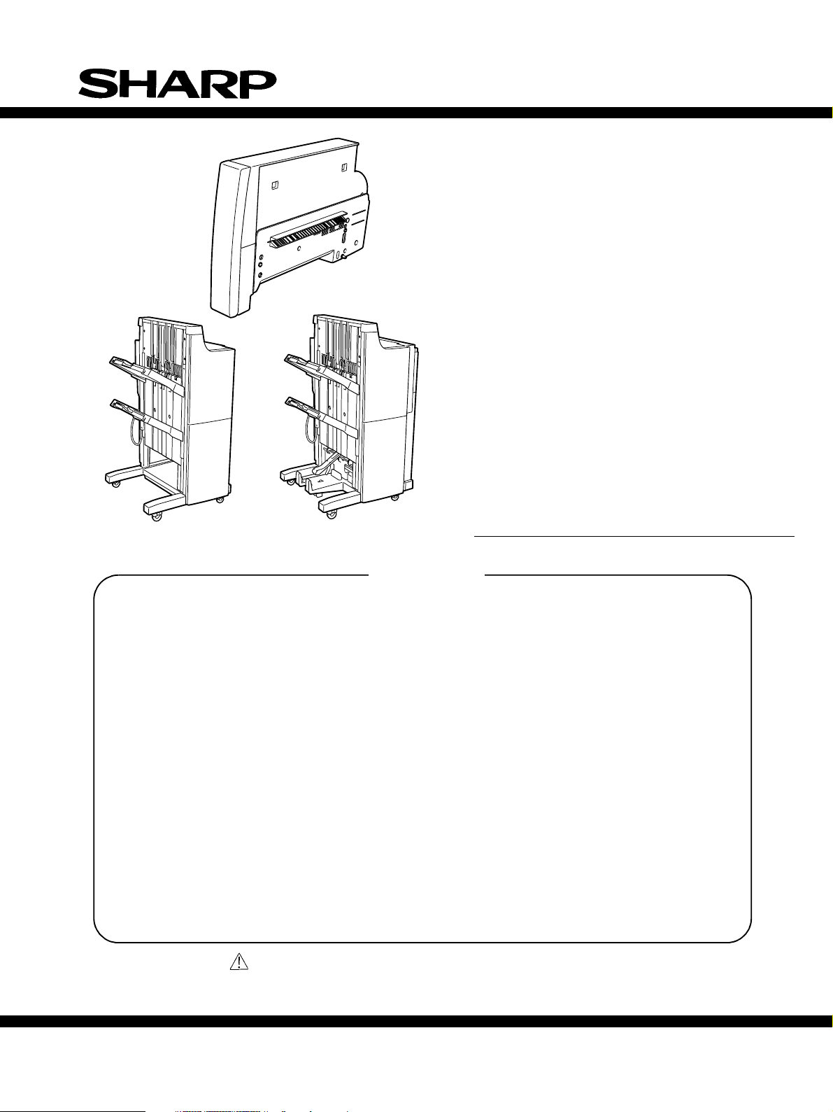
FINISHER
PUNCH UNIT
AR-FN8
AR-FN9
AR-PN2A
AR-PN2B
AR-PN2C
AR-FN8
[1] GENERAL DESCRIPTION . . . . . . . . . . . . . . . . . . . . . . . . . . . . . 1-1
[2] FINISHER UNIT BASIC OPERATION. . . . . . . . . . . . . . . . . . . . . 2-1
[3] SADDLE STICHER UNIT BASIC OPERATION . . . . . . . . . . . . . 3-1
[4] PUNCHER UNIT BASIC OPERATION . . . . . . . . . . . . . . . . . . . . 4-1
[5] MECHANICAL CONSTRUCTION. . . . . . . . . . . . . . . . . . . . . . . . 5-1
[6] MAINTENANCE AND INSPECTION. . . . . . . . . . . . . . . . . . . . . . 6-1
[7] TROUBLESHOOTING . . . . . . . . . . . . . . . . . . . . . . . . . . . . . . . . 7-1
[8] UNPACKING AND INSTALLATION . . . . . . . . . . . . . . . . . . . . . . . 8-1
AR-FN9
CONTENTS
MODEL
AR-PN2D
Parts marked with “ “ are important for maintaining the safety of the set.
Be sure to replace these parts with specified ones for maintaining the safety and performance of the set.
This document has been published to be used for
SHARP CORPORATION
after sales service only.
The contents are subject to change without notice.
Page 2

INTRODUCTION
This Service Manual contains the basic data and figures for the Finisher AR-FN8/Saddle
Finisher AR-FN9 needed to service the machine in the field.
This manual comprises the following chapters:
Chapter 1 “General Description” introduces the finisher’s features, specifications, and
names of parts, and shows how to operate the finisher.
Chapter 2 “Finisher Unit Basic Operation” discusses the principles of operation used for
the finisher mechanical and electrical systems. It also explains the timing at
which these systems are operated.
Chapter 3 “Saddle Finisher Unit Basic Operation” discusses the principles of operation
used for the saddle stitcher unit’s mechanical and electrical systems. It also
explains the timing at which these systems are operated.
Chapter 4 “Puncher (option) Unit Basic Operation” discusses the principles of operation
used for the puncher unit’s mechanical and electrical systems. It also explains
the timing at which these systems are operated.
Chapter 5 “Mechanical System” discusses how the finisher is constructed mechanically,
and shows how it may be disassembled/assembled and adjusted.
Chapter 6 “Maintenance and Inspection” provides tables of periodically replaced parts
and consumables and durables, together with a scheduled servicing chart.
Chapter 7 “Troubleshooting” shows how to troubleshoot possible faults and gives electri-
cal parts arrangement diagrams, LED/check pin diagrams by PCB.
“Appendix” contains diagrams showing tables of signals, overall circuit diagrams and tables of solvents/oils.
Descriptions of installation are not mentioned in this Service Manual as the Finisher/
Saddle Finisher’s packing boxes contain Installation Procedures.
The descriptions in this Service Manual are subject to change without notice for product improvement or other purposes, and major changes will be communicated in the form
of Service Information bulletins.
All service persons are expected to have a good understanding of the contents of this
Service Manual and all relevant Service Information bulletins, and be able to identify and
isolate faults in the machine.
i
Page 3

ii
Page 4

CONTENTS
CHAPTER 1 GENERAL DESCRIPTION
I. FEATURES .................................. 1-1
II. SPECIFICATIONS .......................1-2
A. Finisher specification................ 1-2
B. Punch unit specification .........1-10
C. Cross Section ......................... 1-13
III. Using the Machine ..................... 1-16
A. Removing Paper Jams
from the Finisher Unit ............. 1-16
B. Supplying the Finisher Unit
with Staples ............................ 1-17
C. Removing Staple Jams from
the Finisher Unit .....................1-19
D. Removing Paper Jams from
the Saddle Stitcher Unit
(Saddle Finisher) .................... 1-20
E. Supplying the Saddle Stitcher
Unit with Staples (Saddle
Finisher) .................................1-22
F. Removing Staple Jams
from the Saddle Stitcher Unit
(Saddle Finisher) .................... 1-23
G. Removing Paper Jams from
the Puncher Unit (option) ....... 1-25
H. Removing Punched Scrap
from the Puncher Unit
(option) ...................................1-26
IV. MAINTENANCE BY THE
USER ........................................1-27
A. Maintenance by the User .......1-27
CHAPTER 2 FINISHER UNIT BASIC OPERATION
I. BASIC OPERATION ....................2-1
A. Outline ......................................2-1
B. Outline of Electrical
Circuitry ....................................2-2
C. Inputs to and Outputs from the
Finisher Controller PCB ...........2-4
II. FEED/DRIVE SYSTEM .............2-10
A. Outline ....................................2-10
B. Type of Delivery Paths............2-15
C. Feeding and Delivering .......... 2-18
D. Job Offset ...............................2-21
E. Stapling Operation ................. 2-24
F. Stapler Unit ............................ 2-32
G. Tray Operation ........................2-38
H. Detecting the Height of
Stack on the Tray ....................2-40
I. Shutter Operation ...................2-42
J. Buffer Path Operation ............. 2-46
K. Detecting Jams ......................2-51
III. POWER SUPPLY SYSTEM ....... 2-56
iii
Page 5

CHAPTER 3 SADDLE STITCHER UNIT
BASIC OPERATION
I. BASIC OPERATION ....................3-1
A. Outline......................................3-1
B. Electrical Circuitry ....................3-2
C. Inputs to and Outputs from
the Saddle Stitcher Controller
PCB..........................................3-3
II. FEEDING/DRIVE SYSTEM .........3-8
A. Outline......................................3-8
III. PAPER OUTPUT
MECHANISM............................. 3-14
A. Outline....................................3-14
B. Controlling the Inlet
Flappers .................................3-17
CHAPTER 4 PUNCHER UNIT (OPTION)
BASIC OPERATION
I. BASIC OPERATION ....................4-1
A. Outline......................................4-1
B. Inputs to and Outputs from Punch
Driver PCB ...............................4-2
II. PUNCH OPERATION ..................4-5
C. Controlling the Movement of
Sheets ....................................3-21
D. Aligning the Sheets ................3-23
E. Controlling the Phase of the
Crescent Roller ...................... 3-26
IV. STITCHING SYSTEM ............... 3-29
V. FOLDING/DELIVERY
SYSTEM....................................3-32
VI. CHECKING FOR A JAM............ 3-40
VII. POWER SUPPLY ...................... 3-45
A. Outline...................................... 4-5
B. PUNCH OPERATION ............... 4-7
C. Horizontal Registration
Operation ............................... 4-11
III. POWER SUPPLY SYSTEM .......4-14
CHAPTER 5 MECHANICAL CONSTRUCTION
I. FINISHER UNIT .......................... 5-1
A. Externals and Controls ............. 5-1
B. FEEDING SYSTEM .................5-8
C. PCBs ......................................5-16
II. SADDLE STITCHER UNIT ........5-17
A. Externals and Controls ........... 5-17
iv
B. SADDLE UNIT .......................5-22
C. PCBs ......................................5-32
III. PUNCHER UNIT (OPTION) ...... 5-33
A. Externals and Controls ........... 5-33
B. Puncher Driver System .......... 5-34
C. PCBs ......................................5-39
Page 6

CHAPTER 6 MAINTENANCE AND INSPECTION
I. PERIODICALLY REPLACED
PARTS .........................................6-1
A. Finisher Unit .............................6-1
B. Saddle Stitcher Unit ................. 6-1
C. Puncher Unit (option) ...............6-1
II. CONSUMABLES AND
DURABLES .................................6-2
CHAPTER 7 TROUBLESHOOTING
I. ADJUSTMENTS ..........................7-1
A. Electrical System
(finisher unit) ............................ 7-1
B. Electrical System (saddle
stitcher unit).............................. 7-3
C. Electrical System (puncher
unit (option)) .............................7-5
II. TEST MODE ................................7-7
A. Finisher Unit .............................7-7
B. Saddle Stitcher Unit ................. 7-8
III. ARRANGEMENT OF ELECTRICAL
PARTS .......................................7-10
A. Finisher Unit .............................6-2
B. Saddle Stitcher Unit ................. 6-2
C. Puncher Unit (option) ............... 6-2
III. PERIODICAL SERVICING ..........6-2
A. Finisher Unit ...........................7-10
B. Saddle Stitcher Unit ............... 7-18
C. Puncher Unit (option) ............. 7-26
D. Light-Emitting Diodes (LED) and
Check Pins by PCB ................ 7-30
IV. TROUBLESHOOTING............... 7-32
A. Finisher Unit ...........................7-32
B. Saddle Stitcher Unit ............... 7-42
C. Puncher Unit (option) .............7-50
CHAPTER 8 UNPACKING AND INSTALLATION
I. FINISHER ....................................8-1 II. PUNCH UNIT .............................. 8-6
v
Page 7

APPENDIX
A. SIGNAL AND
ABBREVIATIONS ....................... A-1
B. FINISHER UNIT CIRCUIT
DIAGRAM................................... A-2
C. FINISHER CONTROLLER
PCB ............................................ A-5
D. SADDLE STITCHER UNIT
CIRCUIT DIAGRAM ................. A-15
E. SADDLE STITCHER UNIT
PCB .......................................... A-17
F. PUNCHER UNIT (OPTION)
CIRCUIT DIAGRAM ................. A-25
G. PUNCH DRIVER PCB .............. A-26
H. SOLVENT AND OIL .................. A-29
vi
Page 8

CHAPTER 1
GENERAL DESCRIPTION
I. FEATURES ................................1-1
II. SPECIFICATIONS .....................1-2
A. Finisher specification ...........1-2
B. Punch unit specification .....1-10
C. Cross Section..................... 1-13
III. Using the Machine ...................1-16
A. Removing Paper Jams
from the Finisher Unit......... 1-16
B. Supplying the Finisher Unit
with Staples........................1-17
C. Removing Staple Jams from
the Finisher Unit .................1-19
D. Removing Paper Jams from
the Saddle Stitcher Unit
(Saddle Finisher)................ 1-20
E. Supplying the Saddle Stitcher
Unit with Staples (Saddle
Finisher) .............................1-22
F. Removing Staple Jams
from the Saddle Stitcher Unit
(Saddle Finisher)................ 1-23
G. Removing Paper Jams from
the Puncher Unit (option) ...1-25
H. Removing Punched Scrap
from the Puncher Unit
(option)...............................1-26
IV. MAINTENANCE BY THE
USER ....................................... 1-27
A. Maintenance by the User ...1-27
Page 9
CHAPTER 1 GENERAL DESCRIPTION
I. FEATURES
1. Accommodates large quantities of sheets.
• Normally, the finisher holds a stack of sheets 147 mm in height in its two bins (small-size
paper: equivalent to 1000 sheets)/74 mm in height (large-size paper: equivalent to 500 sheets)
2. Has high paper transportation performance.
• The finisher is capable of handling paper between 60 and 200 g/m2.
3. Offers a job offset function.
• The finisher has a job offset function for sorting non-stapled stacks of copies.
4. Offers four types of auto stapling.
• The finisher offers a choice of four stapling modes (1-point stapling at rear, diagonal stapling
at front, diagonal stapling at rear, 2-point stapling).
5. Uses a buffer roller.
• The use of a buffer roller enables the finisher to accept copies without interruption from the
host machine even during stapling or offset operation.
6. Has a saddle stitch function (Saddle Finisher).
• The finisher can staple along the center of paper and fold it in two (up to 15 sheets).
7. Offers a punch function (option).
• The use of the puncher unit enables the finisher to punch sheets for binders before they are
output. (The puncher unit is capable of handling papers between 64 and 200 g/m2. It cannot
handle special paper, postcards and transparencies.)
ITEM
Finisher
Finisher
Punch unit
Stapler for Finisher
5000 sheets
Stapler for Finisher
2000 sheets
MODEL
AR-FN8
AR-FN9
AR-PN2A
AR-PN2B
AR-PN2C
AR-PN2D
NOTE
Finsher with Saddle Stitching
2 holes (80mm pitch) Europe
2 holes (70mm pitch) 3 holes (108mm pitch) USA/Canada
4 holes (80mm pitch) France
4 holes (70/21mm pitch) Sweden
Staple Car tr ige x1 5000×3 SF-SC11 20
Staple Car tr ige x1 5000×3 SF-SC3 40
Cartridge for AR-FN8 and AR-FN9
Common w ith S5 5,S55N
AR-FN8 and AR-FN9
(For AR-FN9 S addle Stitch)
1-1
Page 10

CHAPTER 1 GENERAL DESCRIPTION
II. SPECIFICATIONS
A. Finisher specifications
1. Basic specifications
a. General
Type
Installation type
Fixing method
Vertical adjustment feature
Distribution system
Paper entry port height
b. Tray section
(1) Functions (Mode)
Simple load (Non-sort)
Job offset load (Sort/Group)
Staple load
Mixed load Size mixed load
Staple mixed load
2-tray finisher * Stretching paper exit tray
Floor installation, field option
Latch method (Fixed with brackets in the upper side of the PPC exit
side)
Available
Tray shift system
683.5mm from the floor surface
Paper sheets of a same size are loaded in the specified bin in
the non-sort mode.
Discharged paper bundles are shifted back and forth to sort.
Stapling is automatically performed.
Paper sheets of different sizes are loaded in the specified bin.
(In the sort/group mode, only sheets of a same width can be
loaded.)
Paper sheets of different sizes (of a same width) are stapled
and loaded in a same bundle in the staple mode.
(2) Applicable paper
Size and load height [mm]
Weight
Kinds
Curl level
Stacking size
*1: Paper sizes and load height are shown below.
*1
Normal paper: 60 - 200g/m
Normal paper, recycled paper
Special paper: Conforming to the body specifications.
10mm or less
AB : A3, A4, A4-R, A5-R, B4, B5, B5-R
Inch : LD, LG, LT, LT-R, FOLIO, COMPUTER
1-2
2
Page 11

CHAPTER 1 GENERAL DESCRIPTION
In the case of simple load, job offset load, and staple load
Mode
Tray No.121212
A5 long, ST long 147mm 147mm X X X X
B5 long 74mm 74mm X X X X
A4 short,
B5 short,
LT short
A4 long, B4 long,
A3 long, LT long,
LG long, LD long,
FOLIO, COMP
Single load (Non-sort) Job offset load (Sort/Group) Staple load
110mm, 750
147mm 147mm 147mm 147mm
74mm 74mm 74mm 74mm
Measuring sensor
Paper transport direction
sheets, or 50
sets, whichever
is reached first.
74mm, 500
sheets, or 50
sets, whichever
is reached first.
110mm, 750
sheets, or 50
sets, whichever
is reached first.
74mm, 500
sheets, or 50
sets, whichever
is reached first.
Stack tray
[Paper load height]
In the case of size/staple mixed load Mode
Mode
Setup Non-sort Sort Group Staple at one point Staple at 2 points
Mixed load of
different widths
Mixed load of A3
and A4
Mixed load of B4
and B5
Mixed load of LD
and LT
Mixed load of LG
and LT-R
74mm X X X X
74mm 74mm 74mm
74mm 74mm 74mm
74mm 74mm 74mm
74mm 74mm 74mm
Size mixed load Staple mixed load
74mm, 500 sheets,
or 50 sets,
whichever is
reached first.
74mm, 500 sheets,
or 50 sets,
whichever is
reached first.
74mm, 500 sheets,
or 50 sets,
whichever is
reached first.
74mm, 500 sheets,
or 50 sets,
whichever is
reached first.
74mm, 500 sheets,
or 50 sets,
whichever is
reached first.
74mm, 500 sheets,
or 50 sets,
whichever is
reached first.
74mm, 500 sheets,
or 50 sets,
whichever is
reached first.
74mm, 500 sheets,
or 50 sets,
whichever is
reached first.
1-3
Page 12

CHAPTER 1 GENERAL DESCRIPTION
c. Staple section
Type
Staple load system
Installation
Fixing
Stapling capacity
Stapling direction
Basic functions
Applicable paper
Auto stapling
Staple empty detection
Size
Weight
Unit assembly type
Staple cartridge (5,000 staples)
Inside of the front cover
Magnet catch
(A4 short, B5 short, LT short): 50 sheets
(A3 long, B4 long, A4 long, LD long, LT long, FOLIO,
COMPUTER): 30 sheets
Face-up stapling
Stapling is automatically performed for every number of
sheets specified in the staple sort mode.
Staple empty in the staple cartridge is automatically detected
by the photo sensor.
* One-point staple in the front
A3 long, B4 long, A4 (long/short), B5 short, LD long, LG
long, LT (long/short), FOLIO, COMPUTER
* One-point staple at that back
A4 long, LG long, LT long, COMPUTER
* One-point staple at the back (Slant staple)
A3 long, B4 long, A4 short, B5 short, LD long, LT short
* Two-point staple
A3 long, B4 long, A4 (long/short), ‚a5 short, LD long, LT
(long/short), COMPUTER, LG long, FOLIO
64 - 80g/m
2
1-4
Kinds
Normal paper, recycled paper
Page 13
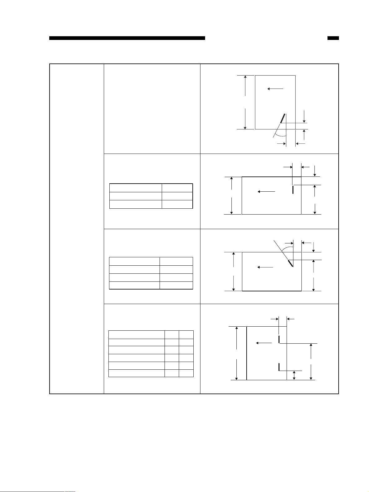
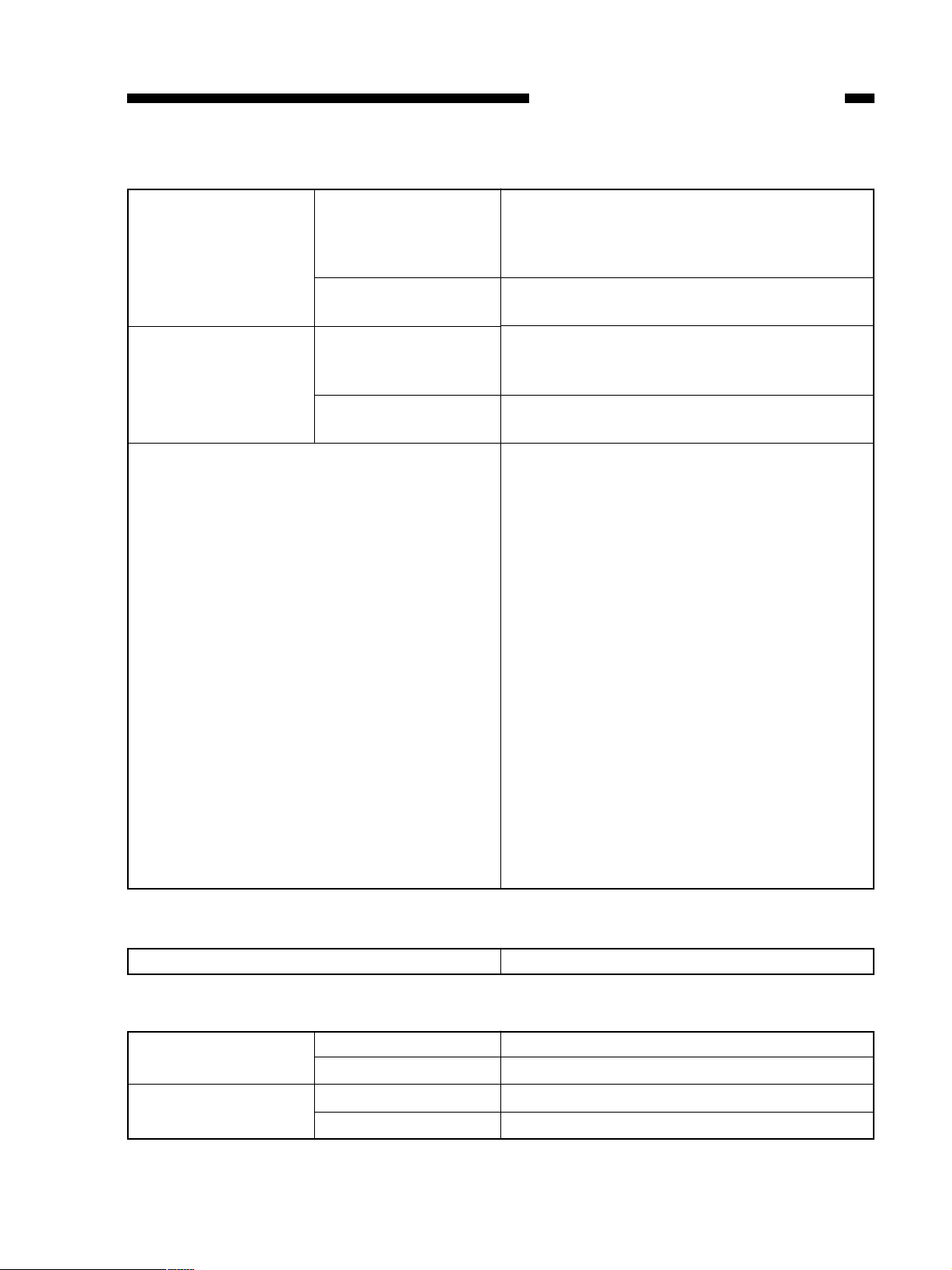
Stapling position One-point staple in the front
CHAPTER 1 GENERAL DESCRIPTION
Paper feeding
direction
* Stapling position range:
The specified value ± 4mm
One-point staple at that back
Size A
A4-Long, FOLIO 204.0
LG-Long, LT-Long 210.0
One-point staple at the back
(Slant staple)
Size A
A3 long, A4 short 291.0
B4 long, B5 short 251.0
LD long, LT short 273.5
Paper width
Paper width
Paper width
(30˚)
Paper feeding
direction
(30˚)
Paper feeding
direction
4.4
4.4
5.0
6.0
A
4.0
6.0
A
Two-point staple
Size A B
A3 long, L4 short 83.0 203.0
A4 long, FOLIO 62.5 138.5
B4 long, B5 short, COMP 63.0 183.0
LD long, LT short 74.0 194.0
LT long, LG LONG 62.5 144.5
Paper width
Paper feeding
direction
5.0
B
A
1-5
Page 14
CHAPTER 1 GENERAL DESCRIPTION
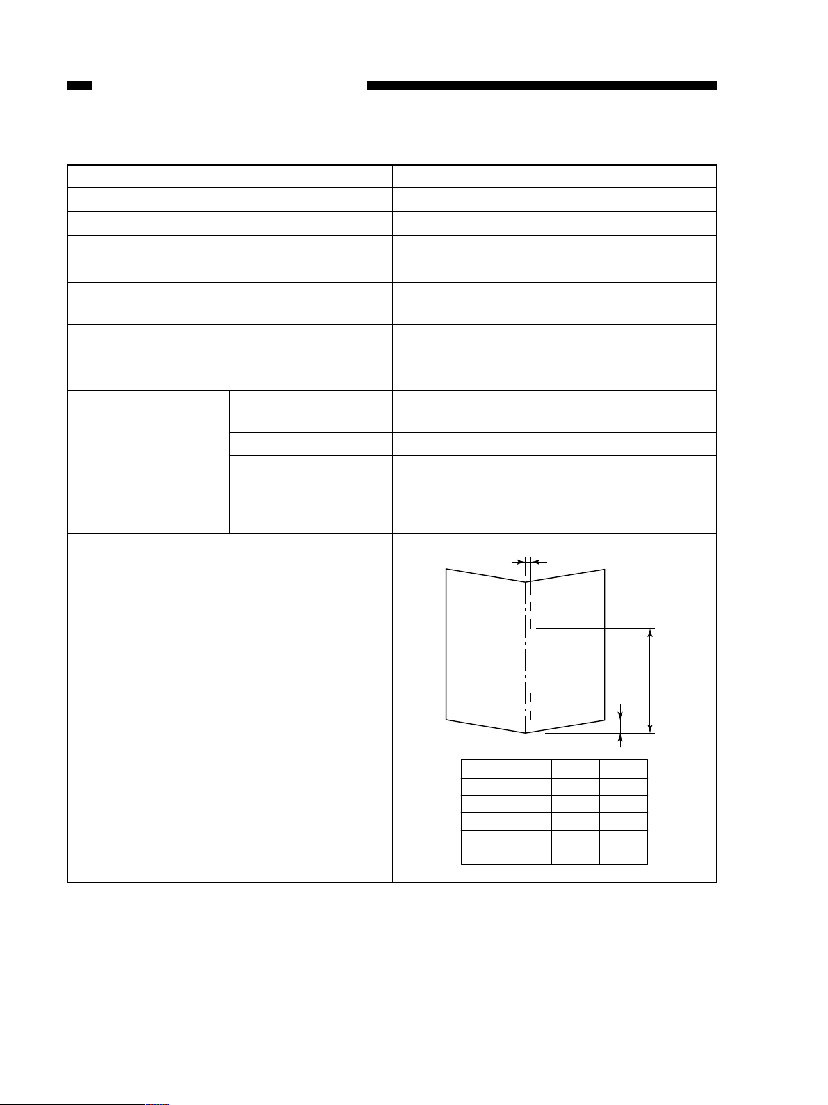
d. Saddle stitch section (AR-FN9 only)
Staple type
Staple load
Staple empty detection
Installing direction
Stapling capacity
Stapling system
Folding position
Applicable paper
Size
Stapling position
Weight
Kind
Load capacity
Unit assembly type
Staple cartridge (2,000 staples)
Available
Inside of the front lower cover
15 sheets
Center stapling, two-fold,
* Fixed stapling pitch
Center folding
* Sheet center adjustment function provided
A3 long, B4 long, A4 long, LD long, LT long
64 - 80g/m
* Cover only: 64 - 200g/m
2
2
Normal paper, recycled paper
Bundle of 11 - 15 sheets: 10 sets
Bundle of 6 - 10 sheets: 20 sets
Bundle of 5 sheets or less: 25 sets
* No stapling for one-folding
±1.0mm or less
1-6
B
A
Size A B
A3 long 83.0 203.0
B4 long 63.0 183.0
A4 long 39.5 159.5
LD long 74.0 194.0
LT long 42.0 162.0
Page 15
2. Machine specifications
CHAPTER 1 GENERAL DESCRIPTION
External dimensions Machine external
dimensions
Package external
dimensions
Weight Machine weight
Package weight
Packed items
W599 x D615 x H1014mm
* Excluding the connection rail and the
projection. With no punch, with latch unit
installed, with sub tray closed.
W1162 x D817 x H951m
* Including the cardboard pallet
About 32kg (AR-FN8) About 52kg (AR-FN9)
* Machine body (excluding the connection
rail)
About 86kg
* Shipping condition
Finisher unit (1)
Installing bracket (1)
Rail (1)
Latch hold plate (1)
Positioning bracket (1)
Tray (2)
Harness cover (Large) (1)
Harness cover (Small) (1)
Latch unit (1)
Latch unit lower cover (1)
IPC board (1)
Locking support (1)
Staple position label (1)
Entry port mylar (1)
TPPAN screw M4x6 (4)
BID screw with washer M4x6 (1)
BID screw with washer M4x20 (4)
DIS screw with washer M4x16 (2)
Step screw (4)
BID screw M4x14 (1)
BID screw M4x6 (2)
3. Electrical specifications
Input voltage DC24V±10% supplied from PPC
4. Environment conditions
Operating conditions 10 - 30°C (without dew)
Transit/storage
conditions
Temperature
Humidity
Temperature
Humidity
20 - 85%RH (without dew)
-10 - 30°C (without dew)
20 - 85% RH (without dew)
1-7
Page 16
CHAPTER 1 GENERAL DESCRIPTION
5. Reliability
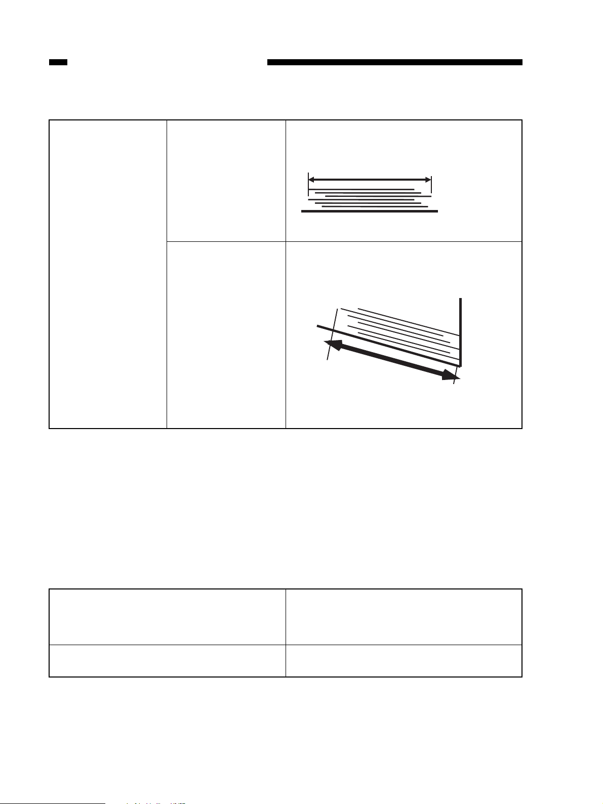
Stack alignment
[Stack section]
Side shift
Lead edge shift
Non-sort, sort, group
L1: 30mm or less
A
L1=A - Paper width
Non-sort, sort, group
L2: 50mm or less
Non-sort, sort, group
B
L2=B - Paper length
(1) Excluding ST-R, A5-R, B5-R
(2) Bundle identification must be valid in the job offset mode.
(3) Side shift quantity is the value at the back edge of paper.
(4) Excluding unexpected error of non-conformity of the standards
(5) Alignment of 750 sheets or more is out of the above specifications.(Loadable)
(6) Alignment of mixed sizes is out of the above specifications. (Loadable)
6. Conforming standards
Safety standards
Obstruction wave standards
(1) UL
(2) C-UL
(3) TUV
(4) CE (Applied by Sharp)
(19 VCCI (As a system)
(2) FCC (IC) (As a system)
1-8
Page 17
CHAPTER 1 GENERAL DESCRIPTION
7. System comparison of AR-S650/650
Paper size and load height (cascade setup)
Mode
Tray no.121212
A5 long, ST long X X X X X X
B5 longXXXXXX
A4 short,
B5 short,
LT short
A4 long, B4 long,
A3 long,
LT long,
LG long,
LD long, FOLIO,
COMP
Simple load (Non-sort/group) Job offset load (Sort) Staple load
X X 125mm 125mm
X X 63mm 63mm
93mm, 637
sheets, or 42
sets, whichever
is reached
first.
63mm, 425
sheets, or 42
sets, whichever
is reached
first.
93mm, 637
sheets, or 42
sets, whichever
is reached
first.
63mm, 425
sheets, or 42
sets, whichever
is reached
first.
Paper size and load height (cascade setup) in mixed load
Mode
Setup Non-sort Sort Group One-point staple Two-point staple
Different width
mixed
A3 and A4 mixed X 63mm X
B4 and B5 mixed X 63mm X
LD and LT mixed X 63mm X
LG and LT-R
mixed
XXXX X
X63mmX
Size mixed load Staple mixed load
63mm, 425 sheets,
or 42 sets,
whichever is
reached first.
63mm, 425 sheets,
or 42 sets,
whichever is
reached first.
63mm, 425 sheets,
or 42 sets,
whichever is
reached first.
63mm, 425 sheets,
or 42 sets,
whichever is
reached first.
63mm, 425 sheets,
or 42 sets,
whichever is
reached first.
63mm, 425 sheets,
or 42 sets,
whichever is
reached first.
63mm, 425 sheets,
or 42 sets,
whichever is
reached first.
63mm, 425 sheets,
or 42 sets,
whichever is
reached first.
1-9
Page 18

CHAPTER 1 GENERAL DESCRIPTION
B. Punch unit specifications
1. Basic specifications
a. General
Installation type Field option
Number of
punch holes and
hole dia.
* For details of
punch positions,
refer to the next
page.
2-hole (Ø6.5)
2-hole/3-hole
auto selection
(Ø8.0)
4-hole (Ø6.5)
4-hole (Ø6.5)
Japan, Europe
North America
France (80mm pitch)
Sweden (70, 21mm pitch)
Punch position adjustment
Allowable
punch size
Punch dust full detection
Allowable weight for punch
Punch life
Display section
Operation panel
2-hole
2-hole/3-hole
auto selection
4-hole (F)
4-hole (S)
Punch hole pitch is fixed.
Punch position adjustment in the back and forth direction is
provided.
A3 long, B4 long, A4 (long/short), B5 (long/short), FOLIO,
LD long, LG long, LT (long/short), COMPUTER
A3 long, A4 short, LD long, LT short (3-hole), LG long, LT
long, COMPUTER (2-hole)
A3 long, A4 short, LD long, LT short
A3 long, B4 long, A4 (long/short), B5 (long/short), FOLIO,
LD long, LG long, LT (long/short), COMPUTER
Available
* Punch dust full and jam are displayed on the copier display.
64 - 200g (OHP sheet or special paper cannot be used.)
1 million sheets (80g paper)
Not provided.
Not provided
* The punch mode can be set with the operation panel of the
copier.
1-10
Page 19

Punch position (Unit : mm)
70 1
12 3
35 3
12 3
(80 1)
(80 1)
(80 1)
40 3
CHAPTER 1 GENERAL DESCRIPTION
2-hole ( Ø 6.5) : Japan/Europe (80mm pitch)
12 3
40 3
80 1
3-hole ( Ø 8.0) : North America
12 3
108 3 108 1
108 1
2-hle ( Ø 8.0) : North America (70mm pitch)
4-hole ( Ø 6.5) : France
4-hole ( Ø 6.5) Sweden
35 3
12 3
(21 1)
(70 1)
(21 1)
1-11
Page 20
CHAPTER 1 GENERAL DESCRIPTION
2. Machine specifications
External dimensions
Weight
Package weight
Machine external
dimensions
Package external
dimensions
Machine weight
Package weight
W76 x D581x H373mm
* Punch dimension does not include the punch
lower cover.
W726 x D514 x H339mm
About 6kg
About 11kg
Punch unit body (1)
Punch lower cover (1)
Jam process label (1)
Saddle jam process label (1)
Connector cover (1)
Body cover stopper (1)
Step screw (long) (1)
Step screw (short) (2)
BID screw M4x16 (1)
BID screw M4x6 (3)
3. Electrical specifications
Input voltage DC24±V10% supplied from PPC
4. Environment conditions
Operating conditions
Transit/storage
conditions
Temperature
Humidity
Temperature
Humidity
10 - 30 ° C (without dew)
20 - 85%RH (without dew)
-10 - 30 ° C (without dew)
20 - 85% RH (without dew)
1-12
Page 21

C. Cross Section
1. Finisher Unit
[1] [2] [3] [4] [5] [6] [7] [8] [9] [10] [11] [18] [19]
CHAPTER 1 GENERAL DESCRIPTION
[1] Tray 1/2
[2] Shutter
[3] Delivery roller
[4] Swing guide
[5] Feed roller 2
[6] Height sensor
[7] Wrap flapper
[8] Buffer roller
[9] Buffer inlet flapper
[10] Saddle stitcher flapper
[17] [12][13][16] [15] [14]
[11] Inlet feed roller
[12] Feed roller 1
[13] Vertical path
[14] Stapler
[15] Knurled belt
[16] Tray lift motor
[17] Saddle stitcher unit
(Saddle Finisher)
[18] Latch unit
[19] Inlet feed section
Figure 1-204
1-13
Page 22

CHAPTER 1 GENERAL DESCRIPTION
2. Saddle Stitcher Unit
[6]
[5]
[4]
[3]
[2]
[1]
[7]
[8]
[9]
[10]
[11]
[12]
1-14
[1] Guide plate
[2] Folding roller
[3] Delivery guide plate
[4] Holding roller
[5] Stitcher (front, rear)
[6] Inlet roller
[7] No. 1 flapper
[8] No. 2 flapper
[9] Stitcher plate (front, rear)
[10] Butting plate
[11] Crescent roller
[12] Paper positioning plate
Figure 1-205
Page 23

3. Puncher Unit (option)
[1]
[2]
CHAPTER 1 GENERAL DESCRIPTION
[3]
[4]
[1] Punch motor
[2] Cam
[3] Hole puncher (Punch blade)
[4] Die
[5] Photosensor PCB
[5]
[6]
[7]
[8]
[9]
[6] LED PCB
[7] Horizontal registration motor
[8] Scrap-full detector PCB unit
[9] Punched scrap container
Figure 1-206
1-15
Page 24
CHAPTER 1 GENERAL DESCRIPTION
IV. USING THE MACHINE
A. Removing Paper Jams
from the Finisher Unit
If the host machine indicates the finisher paper jam message, perform the following to remove the jam.
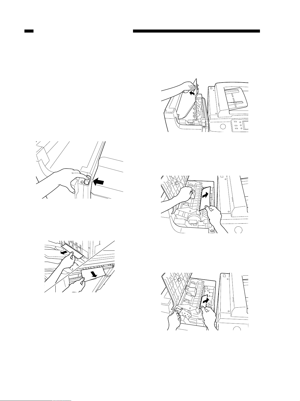
1) Holding the latch lever down as shown,
move it to detach it from the host machine.
3) Open the upper cover and check the inside
of the finisher.
Figure 1-303
4) Lift the buffer roller cover and remove the
jam.
Figure 1-301
2) Remove any jam visible from the outside.
Figure 1-302
Figure 1-304
5) Lift the buffer roller and remove the jam.
Figure 1-305
1-16
Page 25
CHAPTER 1 GENERAL DESCRIPTION
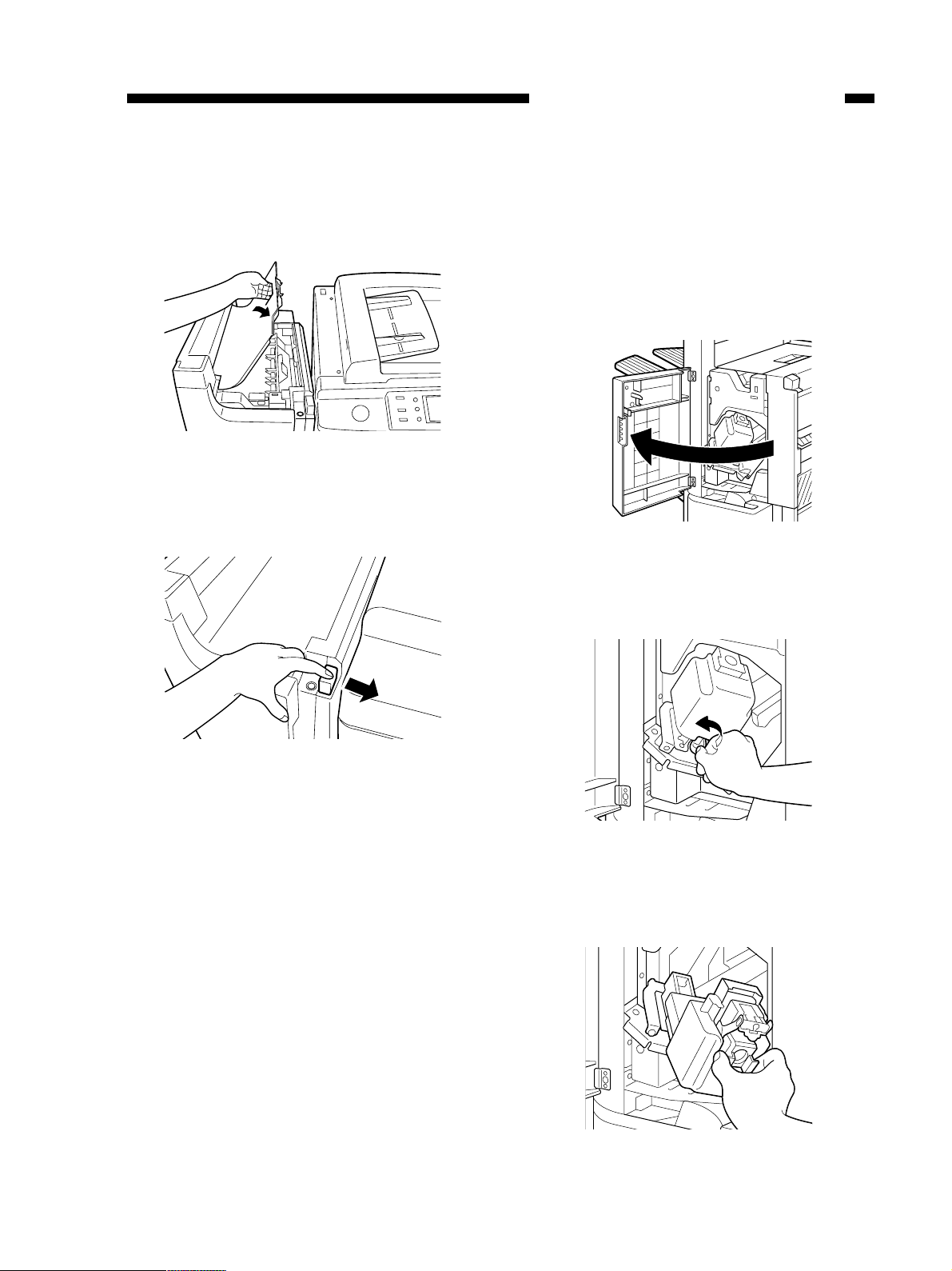
6) Return the buffer roller and the buffer roller
cover to their original positions, and close
the upper cover.
Figure 1-306
7) Connect the finisher to the host machine.
B. Supplying the Finisher Unit
with Staples
If the copier indicates the finisher unit staple
supply message, perform the following to supply it with staples.
1) Open the front door.
Figure 1-308
2) Turn the blue knob counterclockwise.
Figure 1-307
8) Operate as instructed on the display.
Figure 1-309
3) Draw out the staple unit, and pull put the
staple cartridge.
Figure 1-310
1-17
Page 26

CHAPTER 1 GENERAL DESCRIPTION
4) Push the blue knob and pull out the empty
staple case.
Figure 1-311
5) Set a new staple case.
6) Pull the length of tape (used to hold the
staples in place) straight out.
Figure 1-313
7) Set the staple cartridge.
Figure 1-312
Reference:
You may set no more than one staple cartridge
at a time.
Make sure that the new cartridge is one
specifically designed for the finisher unit.
* Do not tear off the seal which fixes the
staples before setting them in the cartridge.
1-18
Figure 1-314
8) Push in the stapler unit completely until it
stops and turn the blue knob clockwise to
lock it and close the front door.
Figure 1-315
Page 27

CHAPTER 1 GENERAL DESCRIPTION
C. Removing Staple Jams
from the Finisher Unit
If the copier indicates the finisher unit staple
jam message, perform the following to remove
the jam.
1) Remove the stack waiting to be stapled from
the delivery tray.
Figure 1-316
2) Open the front door.
4) Draw out the stapler unit and then lift it up.
Figure 1-319
5) Remove the lock of the stopper and open
the staple cover.
* Lift up the metal knob softly to open the
staple cover.
Figure 1-317
3) Turn the blue knob counterclockwise.
Figure 1-318
Figure 1-320
6) Remove the jammed staples.
Figure 1-321
7) Push down the metallic knob and close the
1-19
Page 28
CHAPTER 1 GENERAL DESCRIPTION
staple cover.
8) Return the stapler unit to its original position, and turn the blue knob clockwise to
lock it.
Figure 1-322
9) Close the front door.
Reference:
When the door has been closed, the stapler
unit will automatically execute idle punching
several times to advance the staples.
D. Removing Paper Jams
from the Saddle Stitcher
Unit (Saddle Finisher)
If the host machine indicates the saddle
stitcher unit paper jam message, perform the following to remove the jam.
1) Holding the latch lever down unit as shown,
move it to detach it from the host machine.
Figure 1-323
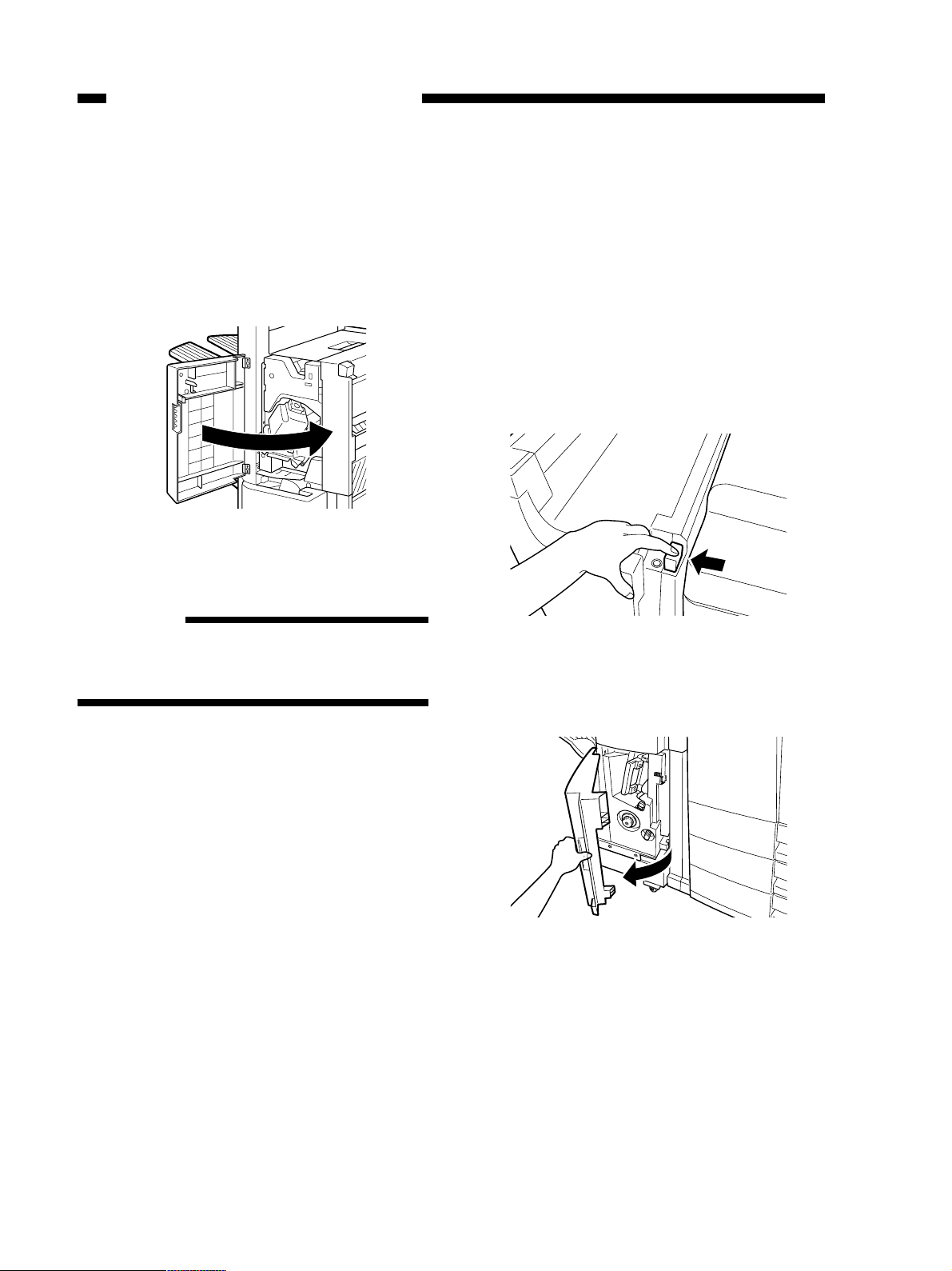
2) Open the front lower door.
1-20
Figure 1-324
Page 29
CHAPTER 1 GENERAL DESCRIPTION
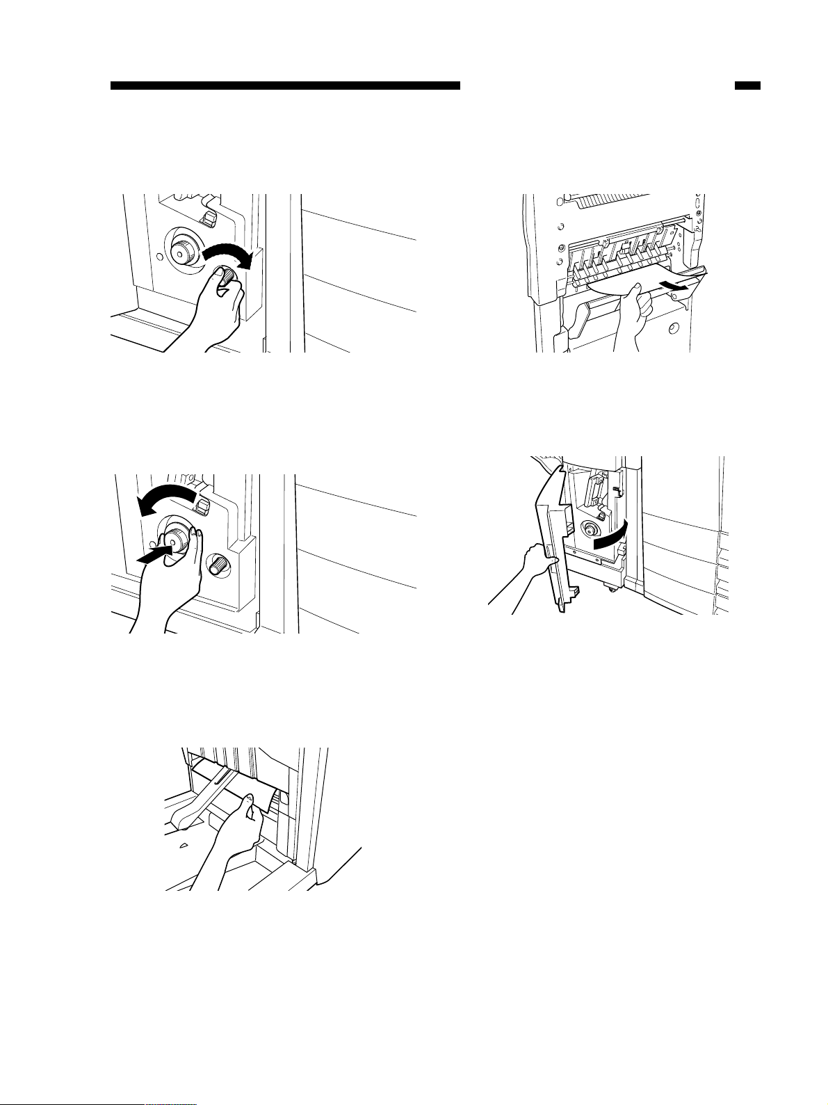
3) Turn the knob clockwise.
Figure 1-325
4) Turn the knob counterclockwise while pushing it in.
6) Open the inlet cover and remove the jam.
Figure 1-328
7) Close the front lower door.
Figure 1-326
5) Remove the jam.
Figure 1-327
Figure 1-329
8) Connect the saddle finisher to the host machine.
9) Operate as instructed on the display.
1-21
Page 30

CHAPTER 1 GENERAL DESCRIPTION
E. Supplying the Saddle
Stitcher Unit with Staples
(Saddle Finisher)
If the host machine indicates the saddle
stitcher unit staple supply message, perform the
following to supply it with staples.
1) Open the front lower door.
Figure 1-330
3) Pull the stitcher unit to the front once and
then shift it up.
Figure 1-332
4) Hold the empty cartridge on its sides and
remove it.
2) Slide out the stitcher unit.
Figure 1-331
Figure 1-333
5) Set a new cartridge.
Figure 1-334
Reference
You must always replace both cartridges at the
same time.
1-22
Page 31

CHAPTER 1 GENERAL DESCRIPTION
6) Pull the stitcher to the front once and then
return it to its original position.
Figure 1-335
7) Push in the stitcher unit and close the front
door.
F. Removing Staple Jams
from the Saddle Stitcher
Unit (Saddle Finisher)
If the host machine indicates the saddle
stitcher unit staple jam message, perform the following to remove the jam.
1) Open the front lower door.
Figure 1-337
Figure 1-336
2) Slide out the stitcher unit.
Figure 1-338
3) Pull the stapler of the stitcher unit to the front
once and then shift it up.
Figure 1-339
1-23
Page 32

CHAPTER 1 GENERAL DESCRIPTION
4) Hold the cartridge on its sides and remove
it.
Figure 1-340
5) Push down on the area identified as A and
pull up the tab identified as B.
7) Return the cartridge to its original position.
Figure 1-343
8) Pull the stitcher of the stitcher unit to the
front once, and then return it to its original
position.
Figure 1-341
6) Remove the staple jam and return the tab B
to its original position.
Figure 1-342
Figure 1-344
9) Push the stitcher unit back to its original
position, and close the front lower door.
Figure 1-345
Reference
Whenever you have removed a staple jam, be
sure to execute staple edging.
1-24
Page 33

CHAPTER 1 GENERAL DESCRIPTION
G. Removing Paper Jams
from the Puncher Unit
(option)
If the display indicates a paper jam on the
puncher unit, perform the following to remove
the jam:
1) Open the front door of the puncher unit.
Figure 1-346
4) Open the upper cover.
Figure 1-349
5) Remove the jam.
2) Align the triangle mark on the knob within
the range marked by .
Figure 1-347
3) Close the front door of the puncher unit.
Figure 1-350
6) Close the upper cover.
Figure 1-351
7) Operate as instructed on the display.
Figure 1-348
1-25
Page 34

CHAPTER 1 GENERAL DESCRIPTION
H. Removing Punched Scrap
from the Puncher Unit
(option)
If the display indicates a punched scrap full
state on the puncher unit, perform the following to remove the punched scrap:
1) Open the front door of the puncher unit.
Figure 1-352
2) Slide out the punched scrap container.
4) Return the punched scrap container to its
original position.
Figure 1-355
5) Close the front door of the puncher unit.
Figure 1-353
3) Discard the punched scrap.
Figure 1-354
Figure 1-356
1-26
Page 35

CHAPTER 1 GENERAL DESCRIPTION
V. MAINTENANCE BY THE USER
A. Maintenance by the User
No.
1
2
Item
Replacing the staple cartridge (finisher unit)
Replacing the staple cartridge (saddle
stitcher unit)
When the appropriate indication is made
on the host machine’s display.
Timing
Note:
The finisher unit and the saddle stitcher unit use different cartridge types. Be sure that the
appropriate type is used for each.
Table 1-401
1-27
Page 36

CHAPTER 2
FINISHER UNIT BASIC OPERATION
1. This chapter discusses the purpose and role of each of the finisher’s functions, and the principles of operation used for the finisher mechanical and electrical systems. It also explains the
timing at which these systems are operated.The symbol in drawings indicates transmission of mechanical drive, and signals marked by together with the signal name indicates
the flow of electrical signals.
2. In descriptions of digital circuits on the finisher, “1” indicates a high signal voltage level, while
“0” indicates a low signal voltage level. Voltage values differ according to the circuit.
A microprocessor is used on the finisher. A description of the microprocessor operation is
omitted in this chapter as it is practically impossible to check the internal operation of the
microprocessor.
Descriptions in this chapter also assume that PCBs will not be repaired at user sites. For this
reason, descriptions of circuits on PCBs are limited to block diagrams. Two types of block
diagrams are provided for separate functions: diagrams indicating details from sensors up to
input sections of major PCBs, and diagrams indicating details from the output sections of
major PCBs up the loads.
I. BASIC OPERATION ..................2-1
A. Outline ................................. 2-1
B. Outline of Electrical
Circuitry................................2-2
C. Inputs to and Outputs from the
Finisher Controller PCB ....... 2-4
II. FEED/DRIVE SYSTEM............ 2-10
A. Outline ............................... 2-10
B. Type of Delivery Paths ....... 2-15
C. Feeding and Delivering ......2-18
D. Job Offset .......................... 2-21
E. Stapling Operation ............. 2-24
F. Stapler Unit ........................2-32
G. Tray Operation....................2-38
H. Detecting the Height of
Stack on the Tray................2-40
I. Shutter Operation...............2-42
J. Buffer Path Operation.........2-46
K. Detecting Jams ..................2-51
III. POWER SUPPLY SYSTEM .....2-56
Page 37

I. BASIC OPERATION
A. Outline
CHAPTER 2 FINISHER UNIT BASIC OPERATION
The finisher is designed to deliver copies arriving from its host machine, and its modes of
delivery include simple stacking, job offset
(Note)
, and stapling.
All operations involved in these modes are controlled by the finisher controller PCB, according
to the appropriate commands from the host machine.
In the case of the Saddle Finisher, copies from the host machine may be routed to the saddle
stitcher unit.
Swing guide drive system
Alignment drive system
Stapler drive system
Delivery drive system
Control system
Feeder drive system
Shutter drive system
Tray drive system
Saddle stitcher unit control system
(Saddle Finisher)
Figure 2-101
Note:
The term job offset refers to shifting each sorting job, separating a single stack into several stacks.
2-1
Page 38

CHAPTER 2 FINISHER UNIT BASIC OPERATION
B. Outline of Electrical Circuitry
The finisher’s sequence of operation is controlled by the finisher controller PCB. The finisher
controller PCB is a 16-bit microprocessor (CPU), and is used for communication with the host
machine (serial) in addition to controlling the finisher’s sequence of operations.
The finisher controller PCB responds to the various commands coming from the host machine
through a serial communications line to drive solenoids, motors, and other loads. In addition, it
communicates the finisher’s various states (information on sensors and switches) to the host machine through a serial communications circuit.
In the case of the Saddle Finisher, the finisher controller PCB not only communicates with the
saddle stitcher controller PCB but also imparts the saddle stitcher unit’s various states (information
on sensors and switches) to the host machine.
The ICs used on the finisher controller PCB are designed for the following:
●
Q1 (CPU)
Controls sequence of operations.
●
Q2 (EEP-ROM)
Backs up adjustment values.
●
Q7
Contains sequence programs.
●
Q8/Q89 (RAM)
Backs up initial setting data.
●
Q4 (communications IC)
Communicates with the host machine and the saddle stitcher unit.
●
Q14 (regulator IC)
Generates 5V.
Figure 2-102 shows the flow of signals between the finisher and the options controller.
2-2
Page 39

CHAPTER 2 FINISHER UNIT BASIC OPERATION
Saddle stitcher
controller PCB
(Saddle Finisher)
Punch driver PCB
(Puncher unit (option))
Host machine
(DC controller PCB CPU)
Finisher controller
PCB communication
Q1
CPU
Q2
EEP-ROM
Q4
Communication
IC
Q7
EP-ROM
Q8/Q89
RAM
Q14
Regulator IC
Figure 2-102
Motor
Solenoid
Switch
Sensor
2-3
Page 40

CHAPTER 2 FINISHER UNIT BASIC OPERATION
C. Inputs to and Outputs from the Finisher Controller PCB
1. Inputs to the Finisher Controller PCB
Finisher controller PCB
PI1
Inlet sensor
Delivery sensor
Stapling tray
sensor
PI3
PI4
J106-3
J134-1
J122-3
-7
-1
-2
-2
-3
-1
-2
-9
-8
-3
-2
-1
-1
-3
-2
-3
-1
-2
J202
-5
-6
-7
J208
-11
-9
-10
J207A
J17-7
J11-3
J9A-1
-9
-8
-2
-1
-3
-2
+5V
PENT
+5V
PDEL
+5V
STPTY
When the sensor detects
paper, “1”.
When the sensor detects
paper, “1”.
When the sensor detects
paper, “1”.
Shutter open
sensor
Alignment guide
home position
sensor
Stapler shift home
position sensor
Tray home
position sensor
PI5
PI6
PI7
PI8
J118-3
J121-3
J129-3
J130-3
-1
-1
-2
-1
-2
-1
-2
-1
-2
-3
-2
-4
-6
-5
-1
-3
-2
-3
-1
-2
J205
-8
-6
-7
J207A
-3
-1
-2
J210
J12B-4
J9A-4
J12A-7
J12A-4
-6
-5
-6
-5
-9
-8
-6
-5
+5V
STOPN
+5V
JOGHP
+5V
STPHP
+5V
TRYHP
When the shutter opens, “1”.
When the alignment guide
is at the home position, “1”.
When the stapler is at the
home position, “1”.
When the tray is at the
home position, “1”.
Figure 2-103
2-4
Page 41

CHAPTER 2 FINISHER UNIT BASIC OPERATION
2. Inputs to the Finisher Controller PCB
Finisher controller PCB
Delivery motor
clock sensor
Tray 1 paper
sensor
Tray 2 paper
sensor
Buffer path paper
sensor
Joint sensor
Door open
sensor
PI10
PI11
PI12
PI14
PI15
PI16
J120-1
J101-3
J102-3
J110-3
J117-3
J113-3
-2
-3
-1
-2
-1
-2
-1
-2
-1
-2
-1
-2
-9
-8
-7
-1
-3
-2
J1010
-1
-3
-2
J1020
-3
-4
-5
J207A
-1
-3
-3
-1
-2
-2
-3
-1
-2
J201
-4
-6
-5
J201
-6
-4
-5
-3
-1
-2
J9A-9
J14-1
J14-4
J24-4
J12A-1
J12B-1
+5V
-8
DELCLK
-7
+5V
-3
FSTTRAY*
-2
+5V
-6
SNDTRAY*
-5
+5V
-6
BUFPASS
-5
+5V
-3
JOINT
-2
+5V
-3
DROPN
-2
While the delivery motor
is rotating, alternately
between “0” and “1”.
When paper is present on
tray 1, “0”.
When paper is present on
tray 2, “0”.
When paper is in the
buffer path, “1”.
When the finisher is joined
with the host machine, “1”.
When the front door is
open, “0”.
Buffer path inlet
paper sensor
Swing guide
open sensor
Tray lift motor
clock sensor 1
Tray lift motor
clock sensor 2
PI17
PI18
PI9
PI19
Sensor PCB
J105-3
J127-3
J400-3
J400-6
J24-1
J11-8
-10
J14-10
-12
-11
+5V
-3
BUFENTR
-2
+5V
SWGOPN
-9
+5V
SFTCLK1
-1
-2
-1
-2
-1
-2
-1
-3
-2
J204
-3
-1
-2
When paper is present at
the buffer path inlet, “1”.
When the swing guide is
open, “1”.
When the tray lift motor
is rotating, alternately
between “1” and “0”.
J14-7
-4
-5
+5V
-9
SFTCLK2
-8
When the tray lift motor
is rotating, alternately
between “1” and “0”.
Figure 2-104
2-5
Page 42

CHAPTER 2 FINISHER UNIT BASIC OPERATION
3. Inputs to the Finisher Controller PCB
Finisher controller PCB
PI20
PS1
J125-1
-2
-3
J114-3
Swing motor
clock sensor
Height sensor
Door switch
N. O.
MS1
Swing guide closed detecting switch 1
N. O.
MS2
J207B
J112
-7
-8
-9
J9B-5
-4
-3
+5V
SWGCLK
When the swing motor is
rotating, alternately between
“0” and “1”.
J6-2
+5V
-1
V0
-3
Vin
-4-1
-1
-2
J5-1
-3
Measures the distance between
the sensor and the top of the
stack on the tray.
+24V
+24VMOVE
DRSW
When the front door
and the upper cover
-5
-4
-3
-4
-2
are closed, “1”.
J5-9
-10
J209
-1
-2
Swing guide closed detecting switch 2
N. O.
MS6
Safety zone switch
J131-3
MS3
N. C.
N. O.
C.
-2
-1
Shutter closed detecting switch
N. C.
N. O.
C.
MS4
Tray upper limit detecting switch
N. C.
MS5
J5-11
-12
J5-4
J7-3
J5-7
J209
J206
J132
-3
-4
-3
-2
-1
-1
-2
Figure 2-105
-5
-6
-2
-1
-8
+24VSTPL
+24VSHIFT
TRAYSAF
SHUTCLD
+24VSHIFT
TRYLIM
SWGGCLD
When the swing
guide is closed, “1”.
When the tray is at
the delivery slot, “1”.
When the shutter is
closed, “1”.
When the tray is at
the upper limit, “0”.
2-6
Page 43

CHAPTER 2 FINISHER UNIT BASIC OPERATION
4. Inputs to and Outputs from the Finisher Controller PCB
Staple home
position sensor
Staple switch
Saddle stitcher
controller PCB
Stapler unit
J206-8 J400-1
-7
-6
-5
-4
-3
Finisher controller PCB
When the stapler is at the home
*
position, “0”.
When staples are present in the
*
cartridge, “0”.
*
When the stapler is connected,
“0”.
-2
-3
-4
-5
-6
Communication line
+24V
Host machine
J500-1J207-1
Figure 2-106
J2-2
3
Communication line
4
5
2-7
Page 44

CHAPTER 2 FINISHER UNIT BASIC OPERATION
5. Outputs from the Finisher Controller PCB
Finisher controller PCB
Flapper solenoid
SL1
Buffer inlet solenoid
SL2
Buffer outlet solenoid
SL3
Paddle solenoid
SL5
Escape solenoid
SL6
-1 -2
J107
-2
-1 -3
J108
-2
-1 -2
J109
-2
-1 -2
J128
-2
-1 -3
J123
-2
-1 -11
-2 -10
J207B
-10 -2
-11 -1
J207A
J12A-10
-11-1
J12B-9
-10-2
J24-7
J9B-1
J9A-10
-11-2
-8-1
-2-1
+24V
When "0", the solenoid is turned on.
FLPSL*
+24V
When "0", the solenoid is turned on.
ENTSL*
+24V
When "0", the solenoid is turned on.
EXITSL*
+24V
When "0", the solenoid is turned on.
PDLSL*
+24V
When "0", the solenoid is turned on.
ESCPSL*
Belt escape solenoid
SL7
First feed motor
M1
2-8
-1 -2
J500
-2
+24V
J12B-7
When "0", the solenoid is turned on.
-1
J10-1
-8
BESCPSL*
-2
-3
B*
-4
A*
-5
B
-6
A
+24V
According to rotation direction/speed,
changes between + and - in sequence.
Figure 2-107
Page 45

CHAPTER 2 FINISHER UNIT BASIC OPERATION
6. Outputs from the Finisher Controller PCB
Delivery motor
Alignment motor
Stapler shift motor
Staple motor
Finisher controller PCB
According to rotation
direction/speed, changes
between + and -.
According to rotation
direction/speed, changes
between + and - in sequence.
MOVE
According to rotation
direction/speed, changes
between + and - in sequence.
According to rotation
direction/speed, changes
between + and -.
Tray lift motor
Swing motor
Second feed motor
Inlet feed motor
According to rotation
direction/speed, changes
between + and -.
According to rotation
direction/speed, changes
between + and -.
According to rotation
direction/speed, changes
between + and -.
According to rotation
direction/speed, changes
between + and - in sequence.
Figure 2-108
2-9
Page 46

CHAPTER 2 FINISHER UNIT BASIC OPERATION
II. FEED/DRIVE SYSTEM
A. Outline
The finisher is designed to operate according to the commands from its host machine to deliver
arriving copies to trays in the appropriate mode: simple stacking, job offset, stapling.
See Figure 2-201 for a diagram of the three modes of delivery (four for the Saddle Finisher).
Method of delivery
Normal delivery tray
Normal
delivery
Saddle stitch delivery (Saddle Finisher only)
Simple stacking
Job offset
Stapling
Figure 2-201
Front diagonal
Rear 1-point
Rear diagonal
2-point
2-10
Normal delivery tray
To saddle stitcher unit
(Saddle Finisher)
Figure 2-202
Page 47

1. Normal Delivery
a. Simple Stacking
The finisher delivers copies directly to the tray.
Tray
Copies
CHAPTER 2 FINISHER UNIT BASIC OPERATION
elivery roller
Figure 2-203
Feed roller 1
Feed roller 2
2-11
Page 48

CHAPTER 2 FINISHER UNIT BASIC OPERATION
b. Job Offset
The finisher forwards all copies of each sort job to the stapling tray. The first sort job on the
stapling tray is delivered with a shift to the front of about 30 mm, and the second sort job is delivered without being shifted. Whether the first copy or the last copy of a sort job should be shifted is
determined by the host machine.
Tray
Each sort job is stacked
alternately.
Figure 2-204
Swing guide
Stapling tray
Results of Delivering 4 Sets
Direction of delivery
Delivery roller
Figure 2-205
Figure 2-206
Stopper
Feed roller 1
Copies handled
by job offset
2-12
Page 49

CHAPTER 2 FINISHER UNIT BASIC OPERATION
c. Stapling
The finisher stacks copies arriving from its host machine on the stapling tray. Then it staples
and delivers the copies to the appropriate tray.
Tray
Copies
Stapling
Swing guide
Delivery roller
Front diagonal stapling
Rear diagonal stapling
Stapling
tray
Stopper
Figure 2-207
Rear 1-point stapling
Feed roller 1
Paper width/2
2-point stapling
Figure 2-208
2-13
Page 50

CHAPTER 2 FINISHER UNIT BASIC OPERATION
2. Saddle Stitch Delivery (Saddle Finisher)
A copy arriving in the finisher from the host machine is routed to the saddle stitcher by the
paper deflecting plate. The saddle stitcher executes stitching and saddling operations on the copy
and then delivers it to the saddle stitcher tray.
For discussions of stacks in the saddle stitcher, see Chapter 3.
To saddle stitcher
Figure 2-209
2-14
Page 51

CHAPTER 2 FINISHER UNIT BASIC OPERATION
B. Type of Delivery Paths
The finisher has three different paper paths for delivery, each selected to suit paper size and
delivery mode.
1. Straight Path
When stacking copies shown in Table 2-201, the copies pass under the buffer roller.
Copy size Length or width 182 mm or less
Typical copy examples A5-R, ST-R, thick stock
Table 2-201
Delivery roller Buffer roller
Figure 2-210
2. Buffer Paper Path 1
When stacking copies shown in Table 2-202, the copies pass over the buffer roller, increasing
the distance between copies.
Copy size Length and width 182 mm or more
Typical copy examples A3, B4, A4,A4R, B5, B5R, L , LG, LT,
LT-R, (excluding transparencies and thick stock)
Table 2-202
Buffer roller
Feed roller 2
Delivery roller
Figure 2-211
2-15
Page 52

CHAPTER 2 FINISHER UNIT BASIC OPERATION
3. Buffer Paper Path 2
This is the paper path when copy sizes shown in Table 2-203 are stacked. A maximum of three
copies (three originals or more in the stapling mode) are wrapped round the buffer roller, during
which job offset and stapling are performed on the stapling tray.
Copy size Length 182 to 232mm, and width 182 to 297mm
Typical copy examples A4, B5, LT, (excluding transparencies and thick stock)
Table 2-203
The following shows paper delivery operation in the case of three originals in the stapling
mode.
1) The first copy is moved in the direction of the buffer roller.
Buffer roller
1st copy
Figure 2-212
2) The first copy wraps around the buffer roller and, at the same time, the second copy arrives
from the host machine.
1st copy
2nd copy
Figure 2-213
2-16
Page 53

CHAPTER 2 FINISHER UNIT BASIC OPERATION
3) The second copy is laid over the first copy and, at the same time, the third copy arrives from the
host machine.
1st copy
2nd copy
3rd copy
Figure 2-214
4) The first, second and third copies are simultaneously pulled into the stapling tray.
2nd copy
3rd copy
1st copy
Figure 2-215
Note:
The third copy as explained here is moved through buffer paper path 1. This fact is omitted from the
discussion to avoid interrupting the sequence of operations.
2-17
Page 54

CHAPTER 2 FINISHER UNIT BASIC OPERATION
C. Feeding and Delivering
1. Outline
The finisher moves copies arriving from the host machine to the delivery tray, stapling tray, or
the saddle stitcher unit (Saddle Finisher) according to the mode of delivery. On the stapling tray,
the copies are subjected to job offset or stapling as instructed by the host machine.
The first feed motor (M1), second feed motor (M8) and inlet feed motor (M9) are stepping
motors, anddelivery motor (M2) is a C motor. These motors are controlled by the microprocessor
(CPU) on the finisher controller PCB, and rotate either clockwise or counterclockwise.
The paper paths are equipped with the following four sensors for detection of paper (arrival,
passage):
●
Inlet sensor (PI1)
●
elivery sensor (PI3)
●
Stapling tray sensor (PI4)
●
Buffer path paper sensor (PI14)
In addition, each delivery tray is equipped with a sensor designed to detect the presence/absence of paper on it.
●
No.1 tray paper sensor (PI11)
●
No.2 tray paper sensor (PI12)
If a copy fails to reach or move past each sensor within a specific period of time, the finisher
controller PCB identifies the condition as a jam, and stops the ongoing operation and at the same
time informs the host machine of the condition. When all doors are closed after the paper jam is
removed, the buffer path inlet paper sensor (PI17) checks whether or not copies are being detected
in addition to the above four sensors (inlet sensor, delivery sensor, stapling tray sensor and buffer
path paper sensor). If the sensors detect a copy, the finisher unit judges that paper jams have not
completely been removed, and sends the paper jam removal signal to the host machine again.
2-18
Page 55

CHAPTER 2 FINISHER UNIT BASIC OPERATION
Finisher controller PCB
Delivery motor drive signal
Alignment motor drive signal
Escape solenoid drive signal ESCPSL
Delivery motor clock signal DELCLK
Swing motor drive signal
Swing motor clock signal SWGCLK
PI19
Shift motor clock detection signal 1 SFTCLK1
Shift motor clock detection signal 2 SFTCLK2
PI9
PI20
M7
M2
PI10
Tray lift motor drive signal
Paddle solenoid drive signal PDLSL
M8 M1 M9M5
SL5
Second feed motor drive signal
First feed motor drive signal
Inlet feed motor drive signal
SL3
SL2
SL1
SL7
M6
Flapper solenoid drive signal FLPSL
Buffer inlet solenoid drive signal ENTSL
Buffer outlet solenoid drive signal EXITSL
Belt escape solenoid drive signal BESCPSL
Stapler motor drive signal
Stapler shift motor drive signal
M3
M4
SL6
Figure 2-216
2-19
Page 56

CHAPTER 2 FINISHER UNIT BASIC OPERATION
Finisher controller PCB
Delivery detection signal PDEL
Buffer path paper detection signal BUFPASS
No.1 tray paper detection signal FSTTRAY
No.2 tray paper detection signal SNDTRAY
Stapling tray paper detection signal STPTY
PI3
PI14
PI11
PI4
PI12
PI17
Buffer path inlet paper detection signal BUFENTR
Inlet paper deteciton signal PENT
PI1
2-20
Figure 2-217
Page 57

CHAPTER 2 FINISHER UNIT BASIC OPERATION
D. Job Offset
1. Outline
In the job offset mode, sort jobs and entire copy groups are shifted to the front for delivery to
the tray, and other copies are delivered to the tray without a shift.
The copies are shifted by the alignment guide. The alignment guide is checked by the align-
ment home position sensor (PI6) to find out whether it is at the home position.
The finisher controller PCB drives the alignment motor (M3) at power-on to return the align-
ment guide to its home position.
The finisher controller PCB stops the delivery motor (M2) when the trailing edge of the copy
has moved past feed roller 2. Then the finisher controller PCB rotates the delivery motor counterclockwise and drives the swing motor (M7).As a result, the drive of the delivery motor is transmitted to the swing guide to move up the guide. When the swing guide open sensor (PI18) detects the
swing guide, the delivery motor stops, and the swing guide is held at the up position.
When the swing guide has moved up, the knurled belts attached to feed roller 2 move the copy
to the stapling tray. The presence of paper on the stapling tray is monitored by the stapling tray
sensor (PI4). (The first sheet is fed to the stapling tray while the swing guide is moving up.)
The finisher controller PCB drives the alignment motor (M3) in advance, and keeps the alignment guide in wait at a point 10 mm behind the trailing edge of a sheet. Whenever one sheet is
moved to the stapling tray, each sheet is aligned, and when the fifth or last sheet in a sort job/group
is fed to the stapling tray, the escape solenoid (SL6) moves the guide plate away and under the
stapling tray. From then on, the alignment motor shifts the sheets to the front by 30 mm.
When the copy has been shifted, the finisher controller PCB rotates the alignment motor counterclockwise to move the alignment guide to a point 7 mm behind the trailing edge of the sheet.
This alignment operation is repeated until alignment of the fifth or last sheet in a sort job is completed. At this time, the swing guide is moved down and is closed, and the delivery motor rotates
clockwise to deliver the sheet.
2-21
Page 58

CHAPTER 2 FINISHER UNIT BASIC OPERATION
Guide plate
Alignment guide
Alignment guide
home position sensor (PI6)
Paper
Escape solenoid
(SL6)
Sequence of Operation (job offset)
Inlet sensor (PI1)
Delivery sensor (PI3)
Inlet feed motor (M9)
First feed motor (M1)
Second feed motor (M8)
Delivery motor (M2)
Staple tray sensor (PI4)
Alignment motor (M3)
Alignment guide home
position sensor (PI6)
Swing motor (M7)
Swing guide open
sensor (PI18)
Swing guide closed
detecting switch 1 (MS2)
Escape solenoid (SL6)
Alignment motor (M3)
Figure 2-218
Start signal
Host machine delivery signal
2-22
: Motor CW rotation : Motor CCW rotation
Figure 2-219
Page 59

CHAPTER 2 FINISHER UNIT BASIC OPERATION
2. Flow of Job Offset Operations
1) The swing guide moves up and, at the same time, the knurled belts move the sheet to the
stapling tray.
Offset sheet
Tray 1/2
Delivery
roller
Stapling tray
Swing guide
Feed roller 2
Knurled belts
Stopper
Figure 2-220
2) The alignment guide shifts the sheet to the front.
Existing stack
Alignment guide
Offset sheet
Figure 2-221
3) The swing guide moves down and, at the same time, the delivery roller delivers the sheet.
Offset sheet
Tray 1/2
Swing guide
Feed roller 2
Knurled belts
Delivery
roller
Stapling tray
Figure 2-222
Stopper
2-23
Page 60

CHAPTER 2 FINISHER UNIT BASIC OPERATION
E. Stapling Operation
1. Outline
The stapler unit staples a stack of as many sheets as specified.
The stapling position differs according to the selected staple mode and paper size.
The stapler unit is checked by the stapler shift home position sensor (PI7) to find out whether
it is at the home position.
When starting operation after power-on, the finisher controller PCB drives the stapler shift
motor (M4) to return the stapler unit to the home position. If the stapler is already at the home
position, it is kept waiting as it is.
Stapler shift motor (M4)
Sheets
Stapler shift home
position sensor (PI7)
Stapler
Figure 2-223
2-24
Page 61

CHAPTER 2 FINISHER UNIT BASIC OPERATION
Paper width/2
Front diagonal stapling
Rear diagonal stapling
2-point stapling
Rear 1-point stapling
Figure 2-224
2-25
Page 62

CHAPTER 2 FINISHER UNIT BASIC OPERATION
2. First Sheet
The finisher controller PCB stops the delivery motor (M2) as soon as the trailing edge of the
first sheet has moved past feed roller 2. Then it rotates the delivery motor clockwise to switch the
gear drive to the swing motor (M7), causing the swing guide to move up. When the swing guide
open sensor (PI18) finds the swing guide at the up position, the swing motor stops, maintaining the
swing guide at the up position.
When the swing guide has moved up, the feed belts of feed roller 2 move the sheet to the
stapling tray. (The first sheet is fed to the stapling tray while the swing guide is moving up.) The
presence of paper on the stapling tray is detected by the stapling tray sensor (PI4).
The finisher controller PCB drives the alignment motor (M3) when the stapling tray sensor has
detected paper to put sheets in order. The alignment plate is kept waiting in advance at a point 10
mm behind the trailing edge of the paper.
The swing guide is kept waiting at the up position until the last sheet is output onto the stapling
tray.
Swing guide
1st sheet
Tray 1/2
Feed roller 2
Knurled belts
Delivery roller
Stapling tray
Stapler
Figure 2-225
2-26
Page 63

Swing guide
Swing guide open
sensor (PI18)
CHAPTER 2 FINISHER UNIT BASIC OPERATION
Swing guide closed
detecting switches 1/2
(MS2/MS6)
Delivery roller
Swing motor
clock sensor
(PI20)
Delivery motor
clock sensor
(PI10)
Swing motor (M7)
Delivery motor (M2)
Figure 2-226
2-27
Page 64

CHAPTER 2 FINISHER UNIT BASIC OPERATION
3. 2nd and Subsequent Sheets
The finisher controller PCB turns on the belt escape solenoid (SL7) before the trailing edge of
the second and subsequent sheets have moved past feed roller 2 to make the feed belt escape. This
operation is performed to reduce the time it takes for the trailing edge of the paper to fall on the
stapling tray, and to improve the product duty. The finisher controller PCB turns on the paddle
solenoid (SL5) as soon as the trailing edge of the second and subsequent sheets have moved past
feed roller 2, causing the drive of the second feed motor (M8) to rotate the paddle. The sheets are
pushed by the paddle and moved to the stapling tray. Almost simultaneously with the trailing edge
of the sheet falling into the stapling tray, the belt escape solenoid is turned off to return the feed
belts that were in the escape position to their original position, and feed the sheet onto the stapling
tray. When the sheet has been output onto the stapling tray, the finisher controller PCB rotates the
alignment motor (M3) to put the sheets in order.
Swing guide
2nd and
subsequent
sheets
Paddles
Feed roller 2
Tray 1/2
Delivery
roller
Stapling tray
Figure 2-227
Knurled belts
SL7
Belt escape solenoid
Stapler
2-28
Page 65

nurled belts
CHAPTER 2 FINISHER UNIT BASIC OPERATION
Escape direction
Belt escape
solenoid (SL7)
Figure 2-228
Paddle
solenoid (SL5)
Paddles
Paddles
2nd and
subsequent sheets
1st sheet
Stapler
M8
2nd feed motor
Stopper
Figure 2-229
2-29
Page 66

CHAPTER 2 FINISHER UNIT BASIC OPERATION
4. Last Sheet
When the last sheet has been put in order, the finisher controller PCB turns on the alignment
motor (M3) to move the alignment guide to the alignment position (to butt the guide against the
stack). Then, the finisher controller PCB rotates the swing motor (M7) counterclockwise to move
the swing guide downwards.
The finisher controller PCB moves the stapler according to the staple mode for stapling.
From then on, it rotates the delivery motor (M2) clockwise to delivery the stack to the tray.
Swing guide
Sheets
Feed roller 2
Knurled belts
Tray 1/2
Delivery
roller
Stapling tray
Stapler
Figure 2-230
2-30
Page 67

Swing guide
CHAPTER 2 FINISHER UNIT BASIC OPERATION
Delivery roller
Swing motor (M7)
Delivery motor (M2)
Figure 2-231
2-31
Page 68

CHAPTER 2 FINISHER UNIT BASIC OPERATION
F. Stapler Unit
Stapling is executed by the stapler motor (M6). A single rotation of the cam by the motor
results in one stapling operation.
The cam is checked by the stapling home position sensor (PI22) to find out whether it is at the
home position.
The stapler motor is controlled by the microprocessor (Q1) on the finisher controller to enable
it to be rotated clockwise or counterclockwise.
When the stapling home position sensor is off, the finisher controller PCB rotates the stapler
motor clockwise until the sensor is turned on so as to return the stapling cam to its initial state.
The presence/absence of staples inside the staple cartridge is detected by the staple switch
(MS8).
The finisher controller PCB does not drive the stapler motor (M6) unless the swing guide
closed detecting switch 2 (MS6) is on (i.e., the swing guide is closed). This is to guard against
injuries that could occur when a finger is stuck inside the stapler.
2-32
Page 69

CHAPTER 2 FINISHER UNIT BASIC OPERATION
Figure 2-232
M6
Stapling home
Staple motor
position detection signal
drive signal
Finisher controller PCB
Figure 2-233
Staple detection signal
2-33
Page 70

CHAPTER 2 FINISHER UNIT BASIC OPERATION
Start signal
Host machine delivery signal
Inlet sensor (PI1)
Delivery sensor (PI3)
Inlet feed motor (M9)
First feed motor (M1)
Second feed motor (M8)
Delivery motor (M2)
Staple tray sensor (PI4)
Alignment motor (M3)
Alignment guide home
position sensor (PI6)
Swing guide open
sensor (PI18)
Swing guide closed
detecting switch 1 (MS2)
Paddle solenoid (SL5)
Belt escape solenoid
(SL7)
Staple motor (M6)
1st sheet
Stacking
2nd sheet
Stapling
Delivery
2-34
Staple home position
sensor (PI22)
Stapler shift motor (M4)
: Motor CW rotation : Motor CCW rotation
Figure 2-234
Page 71

CHAPTER 2 FINISHER UNIT BASIC OPERATION
5. Shifting the Stapler Unit
The stapler unit is moved by the stapler shift motor (M4). Its home position is detected by the
stapler shift home position sensor (PI7). When the start signal arrives from the host machine, the
stapler moves to the center of its movement range. This movement occurs regardless of the selected
mode of delivery, as no specific mode is recognized at this point in time. When the command for
stapling arrives from the host machine after the first sheet has reached the host machine pre-registration sensor, the stapler moves to the staple wait position to suit the appropriate stapling position
and paper size.
See Figures 2-235 and later for an idea of the waiting position according to the stapling mode.
a. Front Diagonal Stapling
The position is the same as the stapling position.
Stopper
Stapling tray
delivery direction
Stopper
Guide plate
Stapler
Figure 2-235
2-35
Page 72

CHAPTER 2 FINISHER UNIT BASIC OPERATION
b. Rear 1-Point Stapling
The stapler is kept waiting at the center position. The stapler is moved to and from the stapling
position for each stapling operation.
Stopper
Stapling position
Wait position
Stapling tray
delivery direction
Stapler
Stopper
Guide plate
Figure 2-236
c. Rear Diagonal Stapling
For LT and B5 sizes, the stapler is kept waiting toward the rear away from the stapling position.
The stapler is moved to and from the stapling position for each stapling operation.
Stapler
Wait position
Stapling position
Stopper
Stapling tray
delivery direction
2-36
Stopper
Guide plate
Figure 2-237
Page 73

CHAPTER 2 FINISHER UNIT BASIC OPERATION
d. 2-Point Stapling
The stapler is kept waiting at the center of paper. Stapling occurs at two points, first at the rear
and then at the front.
Stopper
Stapling position
Wait position
Stapling tray
delivery direction
Stapling position
Stapler
Guide plate
Stopper
Figure 2-238
2-37
Page 74

CHAPTER 2 FINISHER UNIT BASIC OPERATION
G. Tray Operation
The finisher has two delivery trays for normal delivery, each accepting sheets.
Each tray is moved up and down by the tray lift motor (M5).
The position of tray is identified with reference to the number of clock pulses of the tray lift
motor clock sensor 1/2 (PI9/PI19) coming from the tray home position sensor (PI8). The finisher
controller PCB finds out in which direction (up or down) the tray is moving based on combinations
of pulses from the two clock sensors.
The finisher controller PCB drives the tray lift motor (M5) to return the tray to the home
position at power-on. If the tray is already at the home position, it is kept waiting as it is.
The finisher controller PCB moves up and down the tray selected by the host machine so that it
is positioned at the delivery slot.
The upper limit of the tray is detected by the tray upper limit detecting switch (MS5). The
finisher controller PCB stops the drive (up) of the tray lift motor (M5) as soon as the tray upper
limit detecting switch is turned on.
The height of the stack on the tray is identified by the height sensor (PS1), which measures its
distance from the top of the stack. The tray is moved down when the distance between the top of the
stack and the delivery assembly drops to a specific measurement.
The finisher controller PCB cuts off the +24V power of the tray lift motor (M5) as soon as the
safety zone switch (MS3) is turned on while the shutter and the swing guide are open, stopping the
operation of the finisher.
2-38
Page 75

CHAPTER 2 FINISHER UNIT BASIC OPERATION
Tray 1
Tray 2
Tray guide
Tray upper limit detecting
switch (MS5)
Encoder
Tray lift motor clock
sensor 2 (PI19)
Tray lift motor
clock sensor 1 (PI9)
Tray lift motor (M5)
Safety zone switch (MS3)
Tray home position sensor (PI8)
Figure 2-239
2-39
Page 76

CHAPTER 2 FINISHER UNIT BASIC OPERATION
H. Detecting the Height of Stack on the Tray
1. Outline
The number of sheets delivered to the tray and the number of sets (number of stapling operations) are stored in memory by the finisher controller PCB. The height of the stack is checked by
the height sensor (PS1). See Table 2-201 for the maximum loading capacity of each tray.
The finisher controller PCB stops its operation when the conditions in Table 2-201 occur,
informing the host machine that the tray is full.
Stacking
mode
Tr ay
Tray 1
Tray 2
Notes: 1. The capacity for the non-staple sort mode is approximate and computed based on 80 g/m2paper.
2. Alignment for stacks containing of 750 sheets or more is not guaranteed.
3. Stacking height precision is ±7 mm.
Small-size
147 mm high
(1000 sheets)
147 mm high
(1000 sheets)
Non-staple sort Staple sort
Large-size
74 mm high
(500 sheets)
74 mm high
(500 sheets)
Mixed sizes
74 mm high
(500 sheets)
74 mm high
(500 sheets)
Small-size
110 mm high
(750 sheets/
50 sets)
110 mm high
(750 sheets/
50 sets)
Large-size
74 mm high
(500 sheets/
50 sets)
74 mm high
(500 sheets/
50 sets)
Mixed sizes
74 mm high
(500 sheets/
50 sets)
74 mm high
(500 sheets/
50 sets)
Table 2-201
Note:
1. The term “small-size” stands for A4,A5-R, B5, LT, ST-R.
2. The term “large-size” stands for A3, B4, A4-R, B5-R, L , LG, LT-R, FOLIO,
COMPUTER.
2-40
Page 77

CHAPTER 2 FINISHER UNIT BASIC OPERATION
eight sensor (PS1)
Paper
Figure 2-240
2-41
Page 78

CHAPTER 2 FINISHER UNIT BASIC OPERATION
I. Shutter Operation
Before the tray on which sheets are output is shifted by the tray lift motor (M5) to another tray,
the finisher controller PCB closes the shutter mounted on the delivery slot before moving the tray,
protecting the existing stack on the tray from the delivery slot and intrusion of hands.
The shutter moves up (to close) when the second feed motor (M8) rotates counterclockwise,
and is held in position when the motor stops. When the second feed motor rotates counterclockwise
once again, it moves down (to open) to enable delivery.
When the shutter is held at the up position, claws slide out of the swing guide to engage the
back of the shutter. This way, the existing slack and the swing guide engage while the tray is
moved, preventing the guide from opening. The claws slide in when the shutter is moved down to
release the engagement.
The upward movement of the shutter is monitored by the shutter closed detecting switch (MS4),
and the downward movement is monitored by the shutter open sensor (PI5).
See the following diagrams for how these operations take place.
1) The second feed motor rotates counterclockwise to move the shutter up.
2-42
M8
Second feed motor
Figure 2-241
Page 79

CHAPTER 2 FINISHER UNIT BASIC OPERATION
2) The tray lift motor rotates and the new tray moves to the stacking lower limit. The distance of
movement is detected by the tray lift motor clock sensor 1/2 (PI9/PI19).
M5
Tray lift motor
Figure 2-242
3) The second feed motor rotates counterclockwise and the shutter moves down.
M
M8
Second feed motor
Figure 2-243
2-43
Page 80

CHAPTER 2 FINISHER UNIT BASIC OPERATION
4) The tray lift motor rotates and the tray moves to suit the height of the stack. The appropriate
height in relation to the existing stack is checked by the height sensor (PS1).
Height sensor (PS1)
M5
Tray lift motor
Shutter closed
detecting
switch (MS4)
Shutter open
sensor (PI5)
Figure 2-244
Claw
Shutter
Claw
2-44
Figure 2-245
M8
Second feed motor
One-way cam
Page 81

CHAPTER 2 FINISHER UNIT BASIC OPERATION
Sequence Operations (shutter drive)
Move from Tray 1 to Tray 2
Second feed motor (M8)
Tray lift motor (M5)
Shutter closed detecting
switch (MS4)
Shutter open
sensor (PI5)
Height sensor (PS1)
Shutter
closed
Tray
moved
Motor CW rotation Motor CCW rotation
Shutter
opened
Tray
moved
Correct height detected
Figure 2-246
2-45
Page 82

CHAPTER 2 FINISHER UNIT BASIC OPERATION
J. Buffer Path Operation
1. Outline
This machine is provided with a buffer paper path for continuously receiving paper from the
host machine during stapling and job offset operation on the stapling tray. A maximum of three
copies (three originals or more in the stapling mode) are wrapped around the buffer roller. uring
this time, job offset and stapling are performed on the stapling tray.
The following shows operation on the buffer paper path.
1) When the first sheet arrives, the buffer inlet solenoid (SL2) remains off. The first sheet enters
the buffer path.
1st sheet
OFF
SL2
Buffer inlet solenoid
Figure 2-247
2) When the leading edge of the sheet has moved past the buffer path inlet paper sensor (PI17),
the buffer outlet solenoid (SL3) is turned on so as to cause the sheet to wrap around the buffer
roller.
Buffer outlet
solenoid
SL3
ON
Buffer path inlet paper
sennsor (PI17)
2-46
Figure 2-248
Page 83

CHAPTER 2 FINISHER UNIT BASIC OPERATION
3) When the leading edge of the sheet has moved past the buffer path paper sensor (PI14), the
buffer roller stops and waits for the second sheet.
1st sheet
2nd sheet
Buffer path paper
sennsor (PI14)
Figure 2-249
4) When the second sheet arrives and its leading edge reaches the inlet sensor (PI1), the buffer
roller starts to operate once again.
1st sheet
2nd sheet
Inlet sennsor (PI1)
Figure 2-250
2-47
Page 84

CHAPTER 2 FINISHER UNIT BASIC OPERATION
5) The buffer roller continues to rotate, and the second sheet overlaps the first sheet.
2nd sheet
1st sheet
Figure 2-251
6) When the trailing edge of the second sheet has moved past the buffer path paper sensor (PI14),
the buffer roller stops and waits for the third sheet.
2nd sheet
1st sheet
3rd sheet
Buffer path paper
sensor (PI14)
Figure 2-252
2-48
Page 85

CHAPTER 2 FINISHER UNIT BASIC OPERATION
7) When the third sheet arrives and its leading edge reaches the inlet sensor (PI1), the buffer roller
starts to operate once again.
2nd sheet
1st sheet
3rd sheet
Inlet sensor (PI1)
Figure 2-253
8) When the leading edge of the third sheet reaches the inlet sensor (PI1), the buffer outlet solenoid (SL3) goes off so that the path is directed in the direction of delivery. (The actual switchover will occur after the trailing edge of the first sheet has moved past the flapper.)
2nd sheet
Buffer outlet
solenoid
SL3
1st sheet
OFF
3rd sheet
Inlet sensor (PI1)
Figure 2-254
2-49
Page 86

CHAPTER 2 FINISHER UNIT BASIC OPERATION
9) The buffer roller continues torotate, the third sheet overlaps the first and second sheets, and the
three sheets are fed together towards the delivery roller.
Figure 2-255
2-50
Page 87

CHAPTER 2 FINISHER UNIT BASIC OPERATION
K. Detecting Jams
The following sensors are used to detect the presence/absence of paper and to make sure that
sheets are moved properly:
●
Inlet sensor (PI1)
●
elivery sensor (PI3)
●
Stapling tray sensor (PI4)
●
Buffer path paper sensor (PI14)
A jam is identified with reference to the presence/absence of paper at each specific sensor at
the times programmed in the memory of the microprocessor (CPU) on the finisher controller PCB.
When the CPU identifies a jam, it suspends the finisher’s delivery operation and informs the
host machine C controller of the presence of the jam.
The tray 1 paper sensor (PI11) and tray 2 paper sensor (PI12) are not used to detect jams.
PI3
PI14
PI4
PI1
No. Sensor names
PI1 Inlet sensor
PI3 elivery sensor
PI4 Stapler tray sensor
PI14 Buffer path paper sensor
Figure 2-256 Table 2-202
2-51
Page 88

CHAPTER 2 FINISHER UNIT BASIC OPERATION
1. Inlet Sensor Delay Jam
The inlet sensor does not detect paper when feeding an equivalent of 400 mm from when the
host machine delivery signal has been issued.
Host machine delivery signal Host machine delivery signal
Jam check
Inlet sensor (PI1)
Inlet feed motor (M9)
Equivalent of 400 mm
Normal
Jam check
Inlet sensor (PI1)
Inlet feed motor (M9)
Equivalent of 400 mm
Jam
Figure 2-257
2. Inlet Sensor Stationary Jam
The sheet does not move past the inlet sensor when an equivalent of twice the feeding length of
the sheet has been fed after the sensor has been turned on.
Equivalent of size x 2
Jam
Jam check
Inlet sensor (PI1)
Inlet feed motor (M9)
Equivalent of size x 2
Normal
Jam check
Inlet sensor (PI1)
Inlet feed motor (M9)
Figure 2-258
3. Buffer Path Paper Sensor Delay Jam
The buffer inlet sensor does not detect paper when an equivalent of 772 mm has been fed after
the inlet sensor has been turned on.
Equivalent of 772 mmEquivalent of 772 mm
Jam check
Inlet sensor (PI1)
Buffer path paper
sensor (PI14)
First feed motor (M1)
Normal
Jam check
Inlet sensor (PI1)
Buffer path paper
sensor (PI14)
First feed motor (M1)
Jam
Figure 2-259
2-52
Page 89

CHAPTER 2 FINISHER UNIT BASIC OPERATION
4. Buffer Path Paper Sensor Stationary Jam
The sheet does not move past the buffer inlet sensor when an equivalent of twice the feeding
length of the sheet has been fed after the sensor has been turned on.
Jam check
Buffer path paper
sensor (PI14)
First feed motor (M1)
Equivalent of size x 2
Normal
Jam check
Buffer path paper
sensor (PI14)
First feed motor (M1)
Equivalent of size x 2
Jam
Figure 2-260
5. Delivery Sensor Delay Jam
a. Straight Path
The delivery sensor does not detect paper when an equivalent of 476 mm has been fed after the
inlet sensor has been turned on.
Jam check
Inlet sensor (PI1)
Delivery sensor (PI3)
Equivalent of 476 mm
Normal
Jam check
Inlet sensor (PI1)
Delivery sensor (PI3)
Equivalent of 476 mm
Jam
First feed motor (M1)
Second feed motor
(M8)
First feed motor (M1)
Second feed motor
(M8)
Figure 2-261
2-53
Page 90

CHAPTER 2 FINISHER UNIT BASIC OPERATION
b. Buffer Path
The delivery sensor does not detect paper when an equivalent of 550 mm has been fed after the
inlet sensor has been turned on.
Equivalent of 550 mm Equivalent of 550 mm
Jam check
Inlet sensor (PI1)
Normal
Jam check
Inlet sensor (PI1)
Jam
Delivery sensor (PI3)
First feed motor (M1)
Second feed motor
(M8)
Delivery sensor (PI3)
First feed motor (M1)
Second feed motor
(M8)
Figure 2-262
6. Delivery Sensor Stationary Jam
The sheet does not move past the delivery sensor when an equivalent of twice the feeding
length of the sheet has been fed after the delivery sensor has been turned on.
Equivalent of size x 2 Equivalent of size x 2
Jam check
Delivery sensor (PI3)
Second feed motor
(M8)
Delivery motor (M2)
Normal
Jam check
Delivery sensor (PI3)
Second feed motor
(M8)
Delivery motor (M2)
Jam
Figure 2-263
2-54
Page 91

CHAPTER 2 FINISHER UNIT BASIC OPERATION
7. Stapling Tray Sensor Stationary Jam
The sheet does not move past the stapling tray sensor 1 sec. after the delivery motor (M2) has
been turned on.
1 sec 1 sec
am check
Stapling tray
sensor (PI4)
elivery motor (M2)
Normal
am check
Stapling tray
sensor (PI4)
elivery motor (M2)
am
Figure 2-264
2-55
Page 92

CHAPTER 2 FINISHER UNIT BASIC OPERATION
III. POWER SUPPLY SYSTEM
1. Outline
The finisher controller PCB is supplied with 24V C and 5V C power when the host machine
is turned on, 24V C is used to drive the motor solenoids. 5V C is used for sensors and ICs.
24V C and 5V C are also used to feed power from the finisher controller PCB to the saddle
stitcher controller PCB. Power is also supplied to the punch driver PCB when the optional puncher
unit is mounted.
Some of the 24 V C power used to drive the motors is cut off when the door switch (MS1) is
open. The power to the saddle stitcher controller PCB, however, will not be cut off.
Figure 2-301 is a block diagram showing the power supply system.
Host
machine
Saddle stitcher
controller PCB
(Saddle Finisher)
Circuit breaker
(CB1)
Finisher controller PCB
Regulator IC
(Q14)
Figure 2-301
Door switch
(MS1)
5V
24V
Motor
Motor
Solenoid
Sensors
Logic
Punch driver PCB
(Puncher Unit (option))
2. Protection Functions
The 24 V C power line used to drive motors and solenoids is equipped with a circuit breaker
(CB1) for protection against overcurrent. The 24 V line used to drive the first feed motor (M1),
alignment motor (M3), and stapler shift motor (M4) are equipped with a fuse, which is designed to
blow when an overcurrent occurs.
2-56
Page 93

CHAPTER 3
SADDLE STITCHER UNIT
BASIC OPERATION
1. This chapter discusses the purpose and role of each of the stitcher’s functions, and the principles of operation used for the stitcher mechanical and electrical systems. It also explains the
timing at which these systems are operated.
The
by
2. In descriptions of digital circuits on the stitcher, “1” indicates a high signal voltage level, while
“0” indicates a low signal voltage level. Voltage values differ according to the circuit.
A microprocessor is used on the stitcher. A description of microprocessor operation is omitted
in this chapter as it is practically impossible to check the internal operation of the microprocessor.
Descriptions in this chapter also assume that PCBs will not be repaired at user sites. For this
reason, descriptions of circuits on PCBs are limited to block diagrams. Two types of block
diagrams are provided for separate functions: diagrams indicating details from sensors up to
input sections of major PCBs, and diagrams indicating details from the output sections of
major PCBs up the loads.
I. BASIC OPERATION .................. 3-1
A. Outline .................................3-1
B. Electrical Circuitry ................3-2
C. Inputs to and Outputs from
II. FEEDING/DRIVE SYSTEM .......3-8
A. Outline .................................3-8
III. PAPER OUTPUT
MECHANISM ...........................3-14
A. Outline ...............................3-14
B. Controlling the Inlet
symbol in drawings indicates transmission of mechanical drive, and signals marked
together with the signal name indicates the flow of electrical signals.
C. Controlling the Movement of
Sheets................................3-21
D. Aligning the Sheets ............3-23
E. Controlling the Phase of the
the Saddle Stitcher Controller
PCB .....................................3-3
Flappers .............................3-17
IV. STITCHING SYSTEM ..............3-29
V. FOLDING/DELIVERY
VI. CHECKING FOR A JAM ..........3-40
VII. POWER SUPPLY ..................... 3-45
Crescent Roller ..................3-26
SYSTEM ..................................3-32
Page 94

CHAPTER 3 SADDLE STITCHER UNIT BASIC OPERATION
I. BASIC OPERATION
A. Outline
The unit “stitches” (2 points) a stack of sheets delivered by the finisher unit and folds it in two
for delivery. All these operations are controlled by the saddle stitcher controller PCB in response to
commands from the host machine via the finisher unit.
Finisher unit control system
Guide plate drive system
Paper positioning plate
drive system
Control system
Alignment drive system
Stitcher drive system
Delivery drive system
Feed drive system
Paper pushing plate
drive system
Paper folding roller
drive system
Figure 3-101
3-1
Page 95

CHAPTER 3 SADDLE STITCHER UNIT BASIC OPERATION
B. Electrical Circuitry
The sequence of operations used for the saddle stitcher is controlled by the saddle stitcher
controller PCB. The saddle stitcher controller PCB has a microprocessor. This microprocessor is
used to control the sequence of operations and to handle serial communications with the finisher
controller PCB, driving solenoids and motors in response to the various commands from the finisher controller PCB.
The saddle stitcher controller PCB is also used to communicate the state of various sensors and
switches to the finisher controller PCB in serial.
The functions of the major ICs mounted on the saddle stitcher controller PCB are as follows:
●
Q1
Controls the sequence of operations.
●
Q2
Contains the sequence program.
●
Q3
Controls the sequence of operations.
●
Q4
Handles IPC communications.
Electrical circuitry block diagram
Sensor
Switch
Saddle stitcher
controller PCB
Q1 CPU
Finisher controller
Q2
ROM
Q3
RAM
Q4
Communi-
cations IC
PCB
Figure 3-102
Motor
Solenoid
Host machine
3-2
Page 96

CHAPTER 3 SADDLE STITCHER UNIT BASIC OPERATION
C. Inputs to and Outputs from the Saddle Stitcher Controller PCB
1. Inputs to the Saddle Stitcher Controller PCB
Saddle stitcher controller PCB
Paper pushing
plate motor
clock sensor
Front cover
open/closed
sensor
Delivery cover
sensor
Paper folding
motor clock
sensor
Alignment
plate home
position sensor
Tray paper
sensor
PI1S
PI2S
PI3S
PI4S
PI5S
PI6S
J107-1
J104-3
J103-3
J102-1
J101-3
J100-3
J11-15
-2
-3
J11-10
-1
-2
-1
-2
-2
-3
-1
-2
-1
-2
J303-1
-3
-2
J309-1
-3
-2
-1
-3
-2
J502
J402
J209A
-3
-1
-2
J203-3
-1
-2
J209-3
-1
-2
-4
-6
-5
-3
-1
-2
-14
-13
-12
-11
J11-7
J11-6
J11-1
J6-7
+5V
LUNGECLK
+5V
FDR
+5V
-9
EJCVR
-8
+5V
-5
FLDCLK
-4
+5V
-3
JOGHP
-2
+5V
-9
TRYPAR
-8
When the paper pushing plate
motor is rotating, alternately
between “1” and “0”.
When the front cover is open,
“0”.
When the delivery cover is
open, “0”.
When the paper folding motor
is rotating, alternately between
“1” and “0”.
When the alignment plate is
at the home position, “1”.
When paper is present on the
tray, “1”.
Paper
positioning
plate home
position sensor
PI7S
J106-3
J302
J202
J202A
-1
-1
-2
-3
-2
-6
J6-4
-4
-5
-6
-5
+5V
PAPPOS
When the paper positioning
plate is at the home position
sensor, “1”.
Figure 3-103
3-3
Page 97

CHAPTER 3 SADDLE STITCHER UNIT BASIC OPERATION
2. Inputs to the Saddle Stitcher Controller PCB
PI8S
Paper positioning
plate paper sensor
Inlet cover sensor
PI9S
J105-3
-1
-2
J124-3
-1
-2
-1
-3
-2
J301
J201
J201A
-3
-1
-2
J6-1
J10-6
Saddle stitcher controller PCB
-3
-2
-8
-7
+5V
PPOSPAR
+5V
INLTCVR
When paper is present at the
paper positioning plate, “1”.
When the inlet cover is
closed, “1”.
Delivery sensor
Crescent roller
phase sensor
Guide home
position sensor
Paper pushing
plate home
position sensor
Paper pushing
plate top position
sensor
Stitcher unit IN
sensor
PI11S
PI12S
PI13S
PI14S
PI15S
PI16S
J525-3
J126-3
J127-3
J128-3
J129-3
J131-3
-2
-1
-4
-2
-3
J425
-1
-2
-1
-2
-1
-2
-1
-2
-1
-2
-3
-1
-2
J325
-2
-4
-3
J225
-3
-1
-2
J125
J9-1
J9-4
J9-7
J9-10
-12
-11
J9-13
-15
-14
J13-1
+5V
-3
DELV
-2
+5V
-6
FDRLHP
-5
+5V
-9
GIDHP
-8
+5V
LUNGEHP
+5V
LUNGETOP
+5V
-3
STPLHP*
-2
When paper is present in
the delivery sensor unit, “1”.
When the flag of the crescent
roller is at the sensor, “1”.
When the guide is at the home
position, “1”.
When the paper pushing plate
is at the home position, “1”.
When the paper pushing plate
is at the leading edge, “1”.
When the stitcher unit is
housed, “0”.
Vertical path
paper sensor
Paper folding
home position
sensor
3-4
PI17S
PI21S
J132-3
J130-3
-1
-2
-2
-1
-1
-3
-2
J308
J208
J208A
-4
-2
-3
J13-4
J18-1
+5V
-6
VPJM
-5
+5V
-2
PAFLDHP*
-3
When paper is present in the
vertical path, “1”.
When the paper folding roller
is at the home position, “0”.
Figure 3-104
Page 98

CHAPTER 3 SADDLE STITCHER UNIT BASIC OPERATION
3. Inputs to the Saddle Stitcher Controller PCB
No.1 paper sensor
No.2 paper sensor
No.3 paper sensor
Stitcher
home
position
sensor (front)
Staple
sensor (front)
Stitcher
home
position
sensor (rear)
Staple
sensor (rear)
Paper sensor PCB
PI18S
PI19S
PI20S
Stitcher unit (front)
MS7S
MS6S
Stitcher unit (rear)
MS5S
MS4S
J123-5
J315-3
J316-3
Saddle stitcher controller PCB
When paper is present at
the No.1 paper sensor, “1”.
When paper is present at
the No.2 paper sensor, “1”.
When paper is present at
the No.3 paper sensor, “1”.
When the stitcher unit is
J304
J204
J204A
-5
-4
-3
-2
-1
-1
-4
-2
-3
-3
-2
-4
-1
-5
J10-1
+5V
-2
1STPA
-3
2NDPA
-4
3RDPA
-5
J8-3
-5
STCHHP1*
at the home position for
-1
-2
J305
JD2
JD1
J120
-7
-6
-5
J8-10
-1
HKEMP1
-2
STCHHP2*
stitching, “0”.
When no staples are
present, “0”.
When the stitcher unit is
at the home position for
-1
-2
J306
J121
-7
-6
-8
-9
HKEMP2
stitching, “0”.
When no staples are
present, “0”.
Inlet cover switch
N.O.
MS1S
Front cover switch
N.O.
MS2S
Delivery cover switch
N.O.
MS3S
J305
J205
Figure 3-105
J4-1
J4-3
J4-5
-2
-4
-6
+24V
INLTCVRMS
FDROPN
+24U
DELVMS
When the inlet cover
is closed, “1”.
When the front cover
is closed, “1”.
When the delivery
cover is closed, “1”.
3-5
Page 99

CHAPTER 3 SADDLE STITCHER UNIT BASIC OPERATION
4. Outputs from the Saddle Stitcher Controller PCB
Saddle stitcher controller PCB
No.1 paper deflecting solenoid
-1 -2
SL1S
-2
No.2 paper deflecting solenoid
-1 -2
SL2S
-2
Feed plate contact solenoid
-1 -2
SL4S
Feed motor
M1S
-2
-1 -4
-2 -3
-3 -2
-4 -1
Paper folding motor
M2S
Guide motor
M3S
Paper positioning plate motor
M4S
Alignment motor
M5S
J118
J117
J116
J115A
J112-2
J119-5
J114-5
J113-5
+24V
J15-1
When “0”, the solenoid comes
J15-3
-2-1
FLPSL1*
+24V
ON.
When “0”, the solenoid comes
J15-5
-4-1
FLPSL2*
+24V
ON.
When “0”, the solenoid comes
-6-1
J5-1
-2
-3
-4
J4-8
RLNIPSL*
A
A*
B
B*
ON.
The pulse signals change according
to the rotation of the motor.
The states (+ and -) change according
-1
-4
-3
-2
-1
-4
-3
-2
-1
-4
-3
-2
-1
-7
J12-1
-2
-3
-4
-5
J7-6
-7
-8
-9
-10
J7-1
-2
-3
-4
-5
to the rotation of the motor.
+24U
B*
The pulse signals change according
A*
to the rotation of the motor.
B
A
+24U
B*
The pulse signals change according
A*
to the rotation of the motor.
B
A
+24U
B*
The pulse signals change according
A*
to the rotation of the motor.
B
A
3-6
Figure 3-106
Page 100

CHAPTER 3 SADDLE STITCHER UNIT BASIC OPERATION
5. Outputs from the Saddle Stitcher Controller PCB
Stitcher unit (front)
J315-4 J8-4
M7S
Stitcher motor
(front)
Stitcher unit (rear)
J316-4 J8-11-4
M6S
Stitcher motor
(rear)
Paper pushing plate motor
M8S
-5 -5-3
-6 -6-2
-7 -7-1
-5 -12-3
-6 -13-2
-7 -14-1
J305
JD2
J306
J108-1
J120
JD1
J121
-2
Saddle stitcher controller PCB
-4
The states (+ and -) change
according to the rotation
of the motor.
The states (+ and -) change
according to the rotation
of the motor.
J4-9
The states (+ and -) change
-10
according to the rotation
of the motor.
Finisher controller PCB
J131-1 J131-8
-2 -7
-3 -6
-4 -5
-5 -4
J132-1
-2
J132-1
-2
Figure 3-107
J2-1
-2
Communication line
-3
+5V
-4
-5
-6-6 -3
+24V
J1-1
-2
3-7
 Loading...