

Page 1

AR-FN7
CODE : 00ZARFN7//A1E
LASER PRINTER OPTIONS
FINISHER
PUNCH UNIT
AR-FN7
MODEL
CONTENTS
[1] INTRODUCTION. . . . . . . . . . . . . . . . . . . . . . . . . . . . . . . . . . . . 1 - 1
[2] UNPACKING AND INSTALLATION . . . . . . . . . . . . . . . . . . . . . . 2 - 1
[3] OPERATIONAL DESCRIPTION . . . . . . . . . . . . . . . . . . . . . . . . 3 - 1
[4] DISASSEMBLY AND ASSEMBLY. . . . . . . . . . . . . . . . . . . . . . . 4 - 1
[5] MAINTENANCE . . . . . . . . . . . . . . . . . . . . . . . . . . . . . . . . . . . . 5 - 1
[6] ADJUSTMENTS . . . . . . . . . . . . . . . . . . . . . . . . . . . . . . . . . . . . 6 - 1
[7] TROUBLESHOOTING . . . . . . . . . . . . . . . . . . . . . . . . . . . . . . . 7 - 1
[8] SIMULATIONS. . . . . . . . . . . . . . . . . . . . . . . . . . . . . . . . . . . . . . 8 - 1
AR-PN1
[9] ELECTRICAL SECTION . . . . . . . . . . . . . . . . . . . . . . . . . . . . . . 9 - 1
[10] OTHERS . . . . . . . . . . . . . . . . . . . . . . . . . . . . . . . . . . . . . . . . . 10 - 1
• CIRCUIT DIAGRAM
Parts marked with “ “ are important for maintaining the safety of the set.
Be sure to replace these parts with specified ones for maintaining the safety and performance of the set.
This document has been published to be used for
SHARP CORPORATION
after sales service only.
The contents are subject to change without notice.
Page 2
[1] INTRODUCTION
1. Product outline
This unit is installed to the following machines to perform the after-process of output paper from a printer, a copier, or a fax machine.
A. Features
1) Employment of the through-type stapler
Employment of the through-type stapler allows to make saddle stitch by one stapler.
2) 3 kinds of auto staple functions
There are 3 staple positions available. (One position in the front, one position at the back, 2 positions at the center)
3) Saddle stitch function
Up to 10 sheets of paper can be stapled at the center and folded into two and discharged.
4) Punch function (Option)
By installation of a puncher unit, paper can be punched to make holes for a binder. (Applicable for 64 - 128g/m². OHP films cannot be used.)
Applicable models AR-P350 / P450, AR-M350 / M450
DM-3500 / 3501 / 4500 / 4501, DM-3551 / 4551
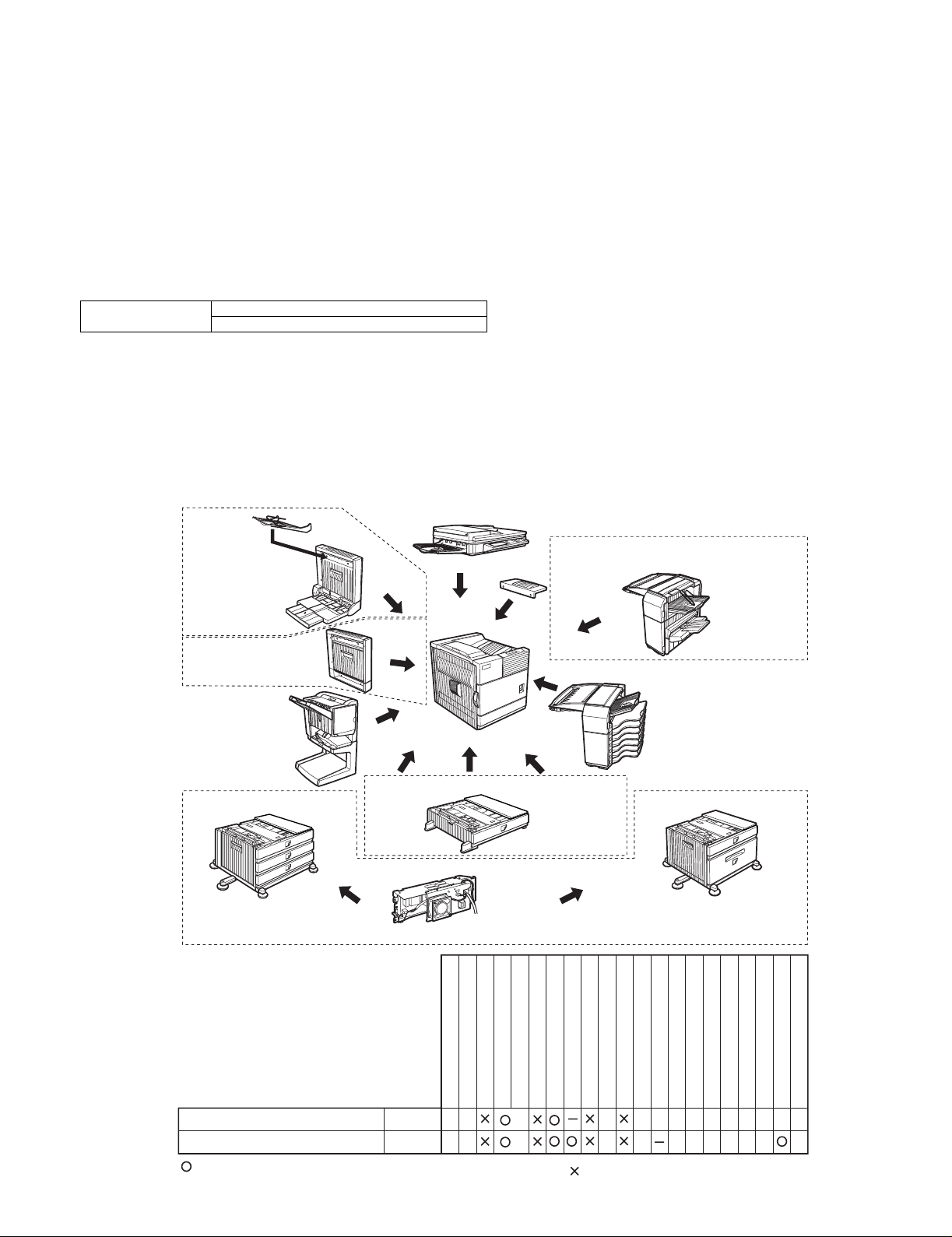
2. Configuration
1. Before installation of this unit, the large-capacity tray (AR-DU3 or AR-DU4) must be installed in advance.
(When installing the AR-DU3/DU4, the option power unit (AR-DC1) is required.)
2. When installing this unit, the duplex module (AR-DU3) must be installed together.
3. This unit cannot be installed with the following units:
•Duplex module (AR-DU4) with the manual paper feed tray
•Paper exit tray (AR-TE4)
•Multi-purpose tray (AR-MU1)
•Finisher (AR-FN6)
Simultaneous
installation
not allowed
AR-DU3
Simultaneous
installation is required
AR-FN7
AR-D14
AR-TE4
Simultaneous installation not allowed
AR-DU4
Simultaneous installation not allowed
AR-MU1
AR-DC1
Simultaneous installation is required
AR-FN6
AR-D13
Output units
Saddle stitch finisher
Punch unit
*1
=Any of the units must be installed together.
B/W scanner module/DSPF
Scanner rack
Multi purpose drawer
Stand/3 x 500 sheet paper drawer
Stand/MPD & 2000 sheet
Duplex module/bypass tray
AR-FN7
AR-PN1
AR-FN7/PN1 INTRODUCTION-1
*1
*1
Duplex module
Saddle stitch finisher
Finisher
Mail-bin stacker
Exit tray
Multi-function controller board
Punch unit
Upper exit tray extension
PS3 expansion kit
Print server card
Network scanner expansion kit
Fax memory (8 MB)
Facsimile expansion kit
Power supply unit
Hard disk drive
Page 3

3. Specifications
A. AR-FN7
(1) Basic specifications
Type Console type finisher
Transport speed 35/45 ppm
Transport reference Center reference
Tray type
(Number of trays)
Paper exit direction Face down
Paper exit paper size A3, B4, A4, A4R, B5, B5R, A5R,
Power consumption 50W or below
Power source Supplied from the option power
External dimensions (W x D x H) 532 x 600 x 467mm
Occupying dimensions (W x D)
Weight About 39kg
(2) Finishing section
Capacity of
paper exit and
load
Offset function Provided
Paper size which
can be stapled
Kinds and
weights of paper
to be discharged
Quantity of paper
to be stapled
(Max.)
Stapling 3 kinds
Staple supply Staple cartridge replacement
Staple detection Staple empty detection
(3) Saddle stitch section
Stapling type Center stapling: Center folding
Stapling position 1200mm pitch from the paper center
Weight of paper applicable f or
saddle stitch
Paper size 64 - 80g/m²
Book tray stacking type Fixed
Quantity of paper to be stapled 10 sets (6 - 10 pages)
Upper tray Lift-up/down offset tray
Lower tray Book tray for saddle stitch
11" x 17", 8.5" x 14", 8.5" x 13",
8.5" x 11", 8.5" x 11"R,
5.5" x 8.5"R
Executive
(DC24V, ???A)
Non-staple 1,000 sheets (Small size)
500 sheets (Large size)
Staple sort 30 sheets
Max 1,000 sheets (Small size)
500 sheets: (Large size)
Large size A3, B4
11" x 17", 8.5" x 14", 8.5" x 13"
Small size A4R, B5, B5R, A5R,
8.5" x 11", 8.5" x 11"R, 5.5" x 8.5"R
Executive
A3, B4, A4, A4R, B5, B5R
11" x 17", 8.5" x 14", 8.5" x 13", 8.5" x 11", .5" x 11"R
Normal paper 60 - 12g/m² (16 - 34lbs)
Index paper 176g/m² (47lbs)
Cover paper 200 - 205g/m², 54 - 55lbs
OHP
50 sheets
(Small size, 128g/m² x 2 + 80g/m² x 48)
25 sheets (Large size, 80g/m² x 25)
Large size A3, B4,
11" x 17", 8.5" x 14", 8.5" x 13"
Small size A4, A4R,
8.5" x 11", 8.5" x 11"R, B5
(One in the front, one at the back: two positions)
2-position stapling: Front stapling, A3, B4, 11" x 17",
8.5" x 14", 8.5" x 13", A4, 8.5" x 11", B5 only
Cartridge empty detection
Staple jam detection
A3, A4R, B4,
11" x 17", 8.5" x 11"R
(Cover: 64 - 128g/m²)
20 sets (1 - 5 pages)
B. AR-PN1
Type Punch unit
No. of punch holes/Hole diameter 2 holes / 6.5mm
Intervals between punch holes 80±1mm
Size of paper applicable for punching Max. A3, Min. B5R
Quantity of paper applicable for punching
AR-FN7/PN1 INTRODUCTION-2
Page 4
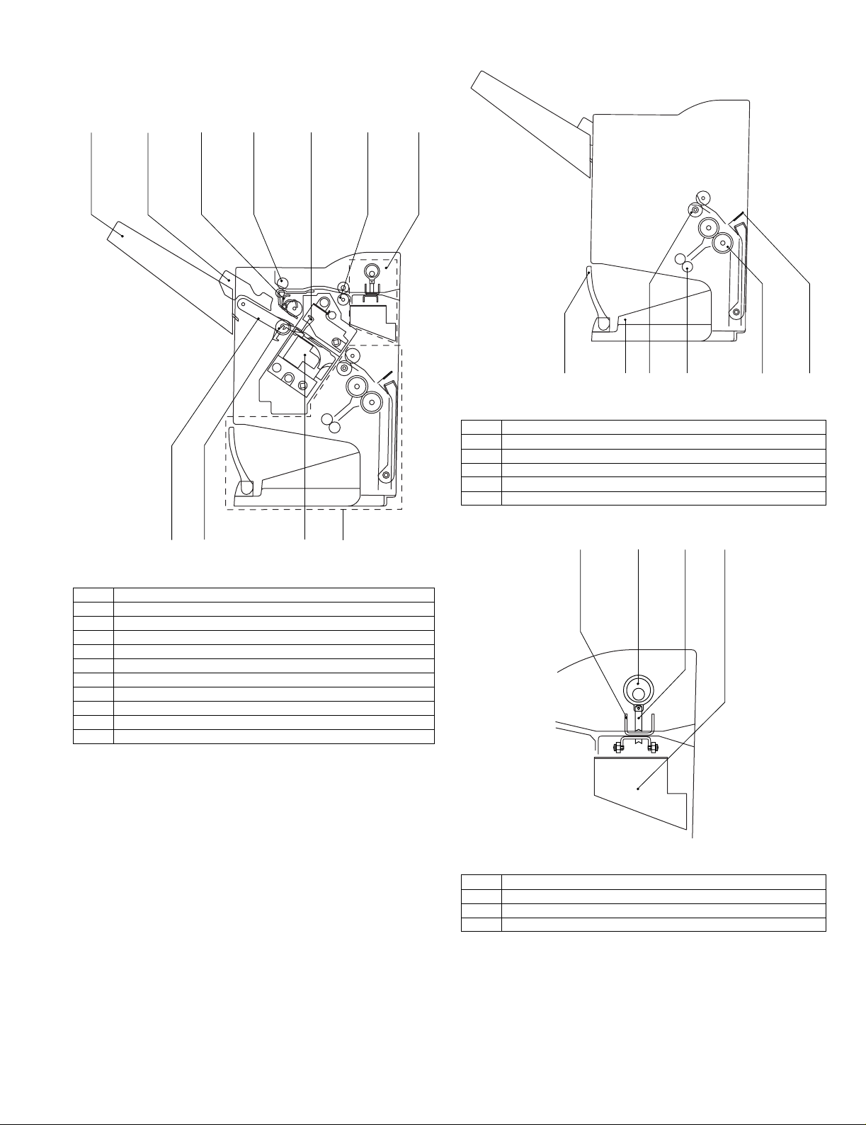
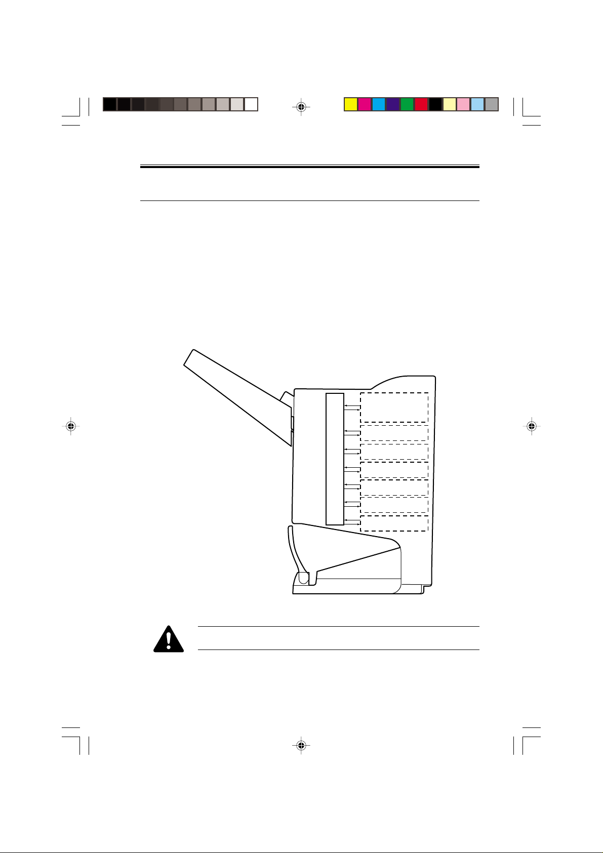
4. Identification of each section
[5]
[3]
[4][2]
[6]
[1]
A. Cross section
(1) Finisher section
[1]
[2]
[3] [7][5][4] [6]
[9]
[8]
[10]
[11]
(2) Saddle section
Fig. F01-301-02
[1] Book making stopper
[2] Book making tray
[3] Bundle transport roller
[4] Book making exit roller
[5] Paper folding roller
[6] Paper pushing plate
(3) Puncher section (Option)
[3][1]
[2]
[4]
Fig. F01-301-01
[1] Paper exit tray
[2] Alignment plate (Front, back)
[3] Paddle
[4] Paper exit roller
[5] Process tray stopper
[6] Transport roller
[7] Puncher section (Option)
[8] Paper exit belt
[9] Bundle exit roller
[10] Stapler
[11] Saddle section
Fig. F01-301-03
[1] Dice
[2] Cam
[3] Punch
[4] Punch dust bo x
AR-FN7/PN1 INTRODUCTION-3
Page 5
[2] UNPACKING AND INSTALLATION
1. AR-FN7
<Before installation>
•For installation of the AR-FN7, the option desk (the AR-D13, a largecapacity paper feed desk, or the AR-D14, a 3-stage paper feed desk)
and the duplex module (AR-DU3) must be installed in advance.
In addition, the power unit (AR-DC1) is also required.
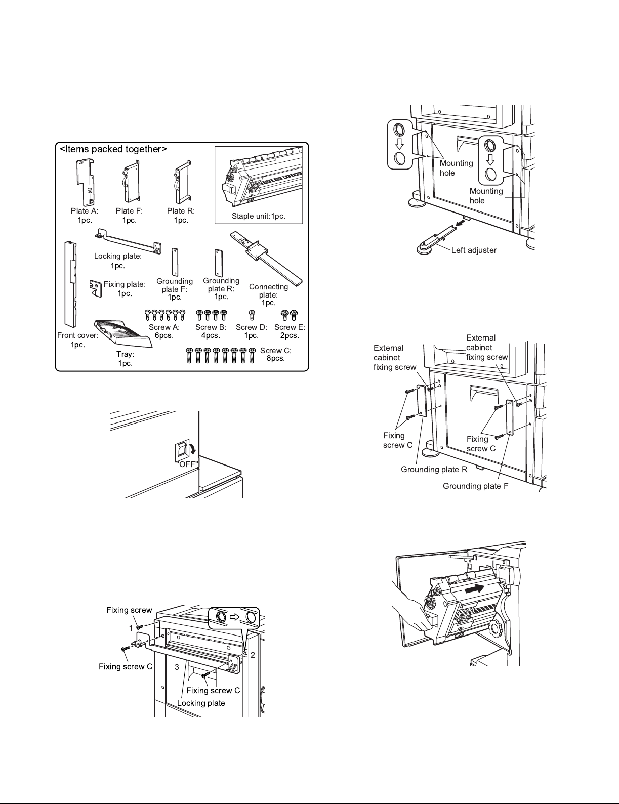
<Items packed together>
Plate A:
1pc.
Plate F:
1pc.
Plate R:
1pc.
Staple unit:1pc.
3) Process the paper feed desk.
<1>Release lock of the left adjuster at the left lower side of the paper
feed desk, and remove the left adjuster.
<2>Use a screwdriver to make 4 holes through 4 installing holes of the
paper feed desk, and remove burs from the holes with a screwdriver
(-).
Mounting
hole
Mounting
hole
Locking plate:
1pc.
"OFF"
Grounding
plate R:
1pc.
Screw B:
4pcs.
Connecting
plate:
Screw D:
1pc.
1pc.
Screw E:
2pcs.
Screw C:
8pcs.
Fixing plate:
1pc.
Front cover:
1pc.
Tray:
1pc.
1) Turn off the main switch of the printer.
<1>Turn off the main switch on the front panel of the printer.
<2>Disconnect the power plug of the printer from the power outlet.
2) Attach the locking plate to the duplex module.
<1>Remove the fixing screw which is on the rear side of the duplex
module.
<2>Use a screwdriver (+) to make a hole through the installing hole in
the front side of the duplex module. Remove burrs with a screwdriv er
(-) from the hole.
<3>Install the locking plate to the duplex module with two fixing screws.
Grounding
plate F:
1pc.
Screw A:
6pcs.
Left adjuster
4) Attach a grounding plate to the paper feed desk.
<1>Remove two screws which are fixing the external cabinet of the
paper feed desk.
<2>Install the grounding plate F and the grounding plate R to the paper
feed desk with fixing screws (2pcs. for each).
External
External
cabinet
cabinet
fixing screw
fixing screw
Fixing
screw C
Fixing
screw C
Grounding plate R
Grounding plate F
5) Install the staple unit to the finisher.
<1>Open the front cabinet of the finisher, and insert the staple unit into
the finisher.
Fixing screw
1
Fixing screw C
2
3
Fixing screw C
Locking plate
AR-FN7/PN1 UNPACKING AND INSTALLATION-1
Page 6
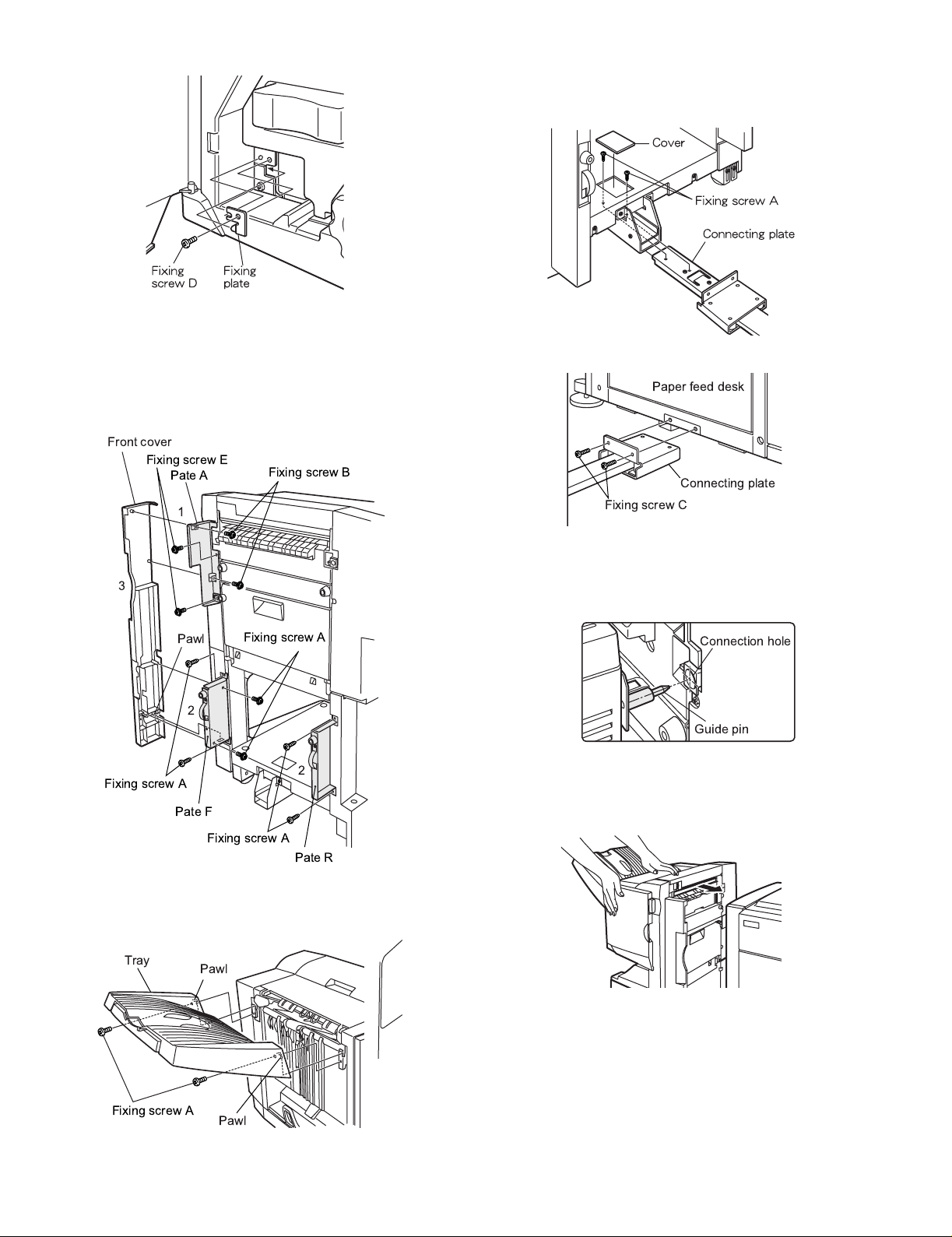
<2>Install the fixing plate with the fixing screw.
6) Install the cover to the finisher.
<1>Install plate A to the position shown in the figure below, and fix it with
two fixing screws.
<2>Install plate F and plate r to their position shown in the figure below
and fix them with fixing screws (2 pcs. for each).
<3>Inser t the pawl of the lower side of the front cover into the mounting
hole of plate F, and fix it with four fixing screws.
Front cover
Fixing screw E
Pate A
Fixing screw B
1
8) Connect the finisher to the paper feed desk.
<1>Remove the cover from the finisher stand.
<2>Install the connecting plate to the finisher with two fixing screws A.
<3>Install the cover to the original position.
<4>Install the finisher to the paper feed desk with two fixing screws C.
Paper feed desk
Connecting plate
Fixing screw C
3
Pawl
Fixing screw A
2
2
Fixing screw A
Pate F
Fixing screw A
Pate R
7) Install the tray.
<1>Hang two pawls of the tray on the installing section of the machine,
and fix them with two fixing screws A.
Tray
Pawl
9) Check and adjust the height of the finisher.
* Move the finisher toward the printer, and check to insure that the
guide pin of the locking plate in inserted into the connection hole of
the finisher smoothly. If not, adjust as follows.
Connection hole
Guide pin
a. When the guide pin of the locking plate is aligned with the
connection hole of the finisher:
<1>Push the finisher into the machine.
Fixing screw A
Pawl
<2>If the upper and lower clearances between the printer and the
finisher are not even, remove the cap on the front/rear side of the
finisher stand with a screwdriver, remove the fixing screw (1pc for
each) of the sub cover in the front/rear side, and remove the sub
cover.
<3>Loosen the fixing screws (4 pcs.) in the adjustment section of the
finisher shown in the figure, and adjust the height adjustment screws
the front and at the back so that the clearances are even.
AR-FN7/PN1 UNPACKING AND INSTALLATION-2
Page 7
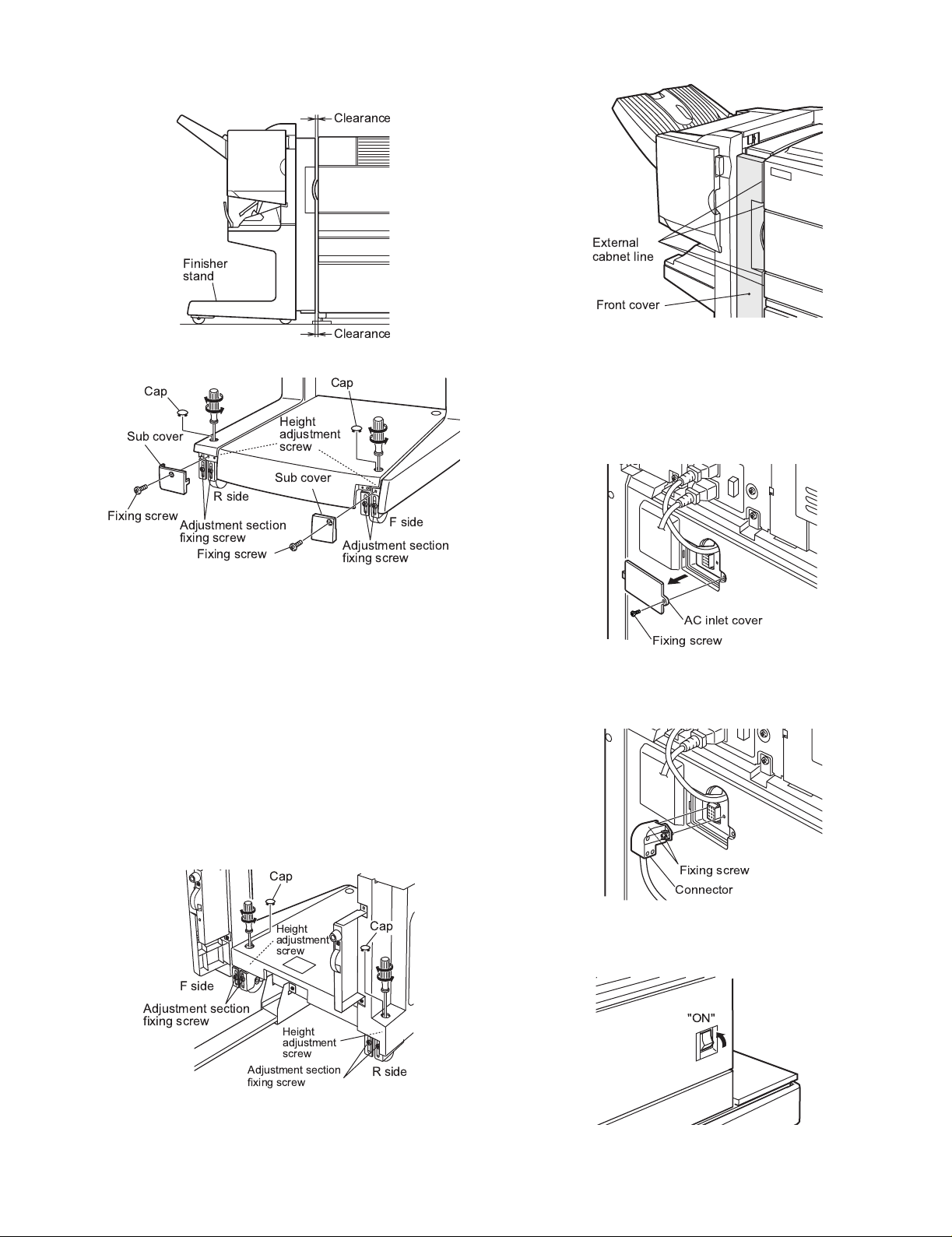
<4>When the clearances are adjusted to be even, tighten the fixing
e
e
Fixing screw
Connector
screws (4 pcs.) in the adjustment section, and install the cap and the
sub cover.
Clearanc
Finisher
stand
External
cabnet line
Front cover
Clearanc
Cap
Cap
Height
Sub cover
adjustment
screw
Sub cover
R side
Fixing screw
Adjustment section
fixing screw
Fixing screw
Adjustment section
fixing screw
F side
b. When the guide pin of the locking plate is not aligned with the
connection hole of the finisher:
<1>For the rear side, loosen the two fixing screws of the adjustment
section at the rear as shown in the figure.
<2>Turn the height adjustment screw to adjust so that the guide pin of
the locking plate is aligned with the connection hole of the finisher.
<3>For the front side, remove the cap from the front side of the finisher
stand with a screwdriver (-). Loosen the fixing screw of the
adjustment section on the front side similarly to the rear side. Tu rn
the height adjustment screw to adjust so that the external line of the
finisher front cover is aligned with the external line of the machine as
shown in the figure.
<4>Check that the guide pin is inserted into the hole smoothly, and
tighten the fixing screws of the adjustment section on the front side
and the rear side.
<5>Perform the clearance adjustment between the finisher and the
printer with procedures of a.
10) Remove the AC inlet cover from the rear cabinet of the paper feed
desk.
<1>Remove the fixing screw of the AC inlet cover, and remove the AC
inlet cover.
AC inlet cover
Fixing screw
11) Connect the connector of the finisher.
<1>Connect the connector of the finisher to the paper feed desk.
<2>Tighten the fixing screw of the connector.
F side
Adjustment section
fixing screw
Cap
Height
adjustment
screw
Height
adjustment
screw
Adjustment section
fixing screw
Cap
12) Turn on the main switch of the printer.
<1>Insert the power plug of the printer into the power outlet.
<2>Turn on the main switch of the printer.
R side
AR-FN7/PN1 UNPACKING AND INSTALLATION-3
"ON"
Page 8
2. AR-PN1
<Before installation>
* For installation of the AR-PN1, the saddle finisher (AR-FN7) must be
installed in advance.
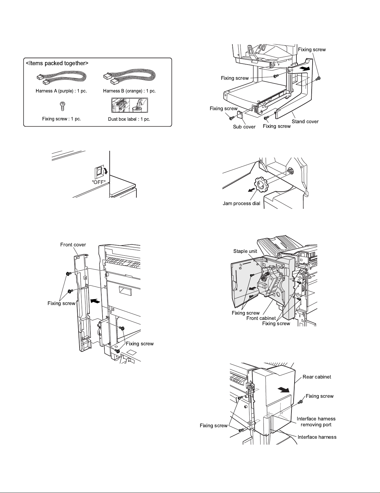
<Items packed together>
<2>Remove the fixing screw of the sub cover, and remove the sub cover.
<3>Remove three fixing screws of the stand cover, and remove the stand
cover.
Fixing screw
Fixing screw
Harness A (purple):1pc.
Fixing screw:1pc.
1) Turn off the main switch of the printer.
<1>T urn off the main swit ch of the printer.
<2>Disconnect the power plug of the printer from the power outlet.
2) Remove the right front cover of the finisher.
<1>Remove four fixing screws of the front cover, and remove the front
cover.
Front cover
Harness B (orange):1pc.
Dust box label:1pc.
"OFF"
Fixing screw
Sub cover
3) Remove the front cabinet and the rear cabinet of the finisher.
<1>Open the front cover of the finisher , and remove the jam process dial.
Jam process dial
<2>Remove four fixing screws of the front cabinet, and pull out the stapl e
unit until it stops, and remove the front cabinet.
Staple unit
Fixing screw
Stand cover
Fixing screw
Fixing screw
<3>Remove three fixing screws of the rear cabinet, and remove the rear
Fixing screw
AR-FN7/PN1 UNPACKING AND INSTALLATION-4
cabinet.
* At that time, remove the interface harness from the rear cabinet
removing port.
Fixing screw
Front cabinet
Fixing screw
Rear cabinet
Fixing screw
Interface harness
removing port
Interface harness
Page 9
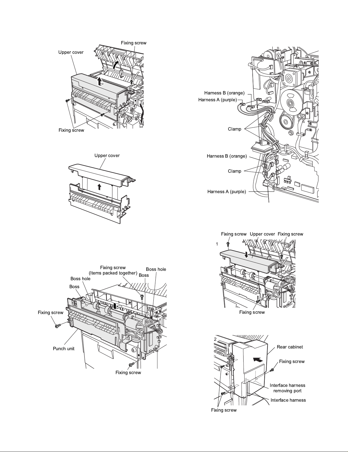
4) Remove the upper cover.
Harness A (purple)
Harness A (purple)
Harness B (orange)
Harness B (orange)
Clamp
Clamp
<1>Remove three fixing screws of the upper cover, and remove the
upper cover.
Fixing screw
Upper cover
Fixing screw
<2>Disengage four pawls of the removed upper cover, and separate it
into upper and lower portions, and reuse the upper portion.
Upper cover
6) Connect the punch unit harness to the finisher PWB.
<1>Remove the clamp which is fixing the harness. Wire the harness A
(purple) and harness B (orange) as shown in the figure, and fix them
with the clamp.
5) Install the punch unit.
<1>Insert two bosses of the punch unit into the boss holes of the fini sher,
Note:Use one fixing screw which is packed together and two fixing
and fix the unit with three fixing screws.
screws which were removed in procedure 4).
Fixing screw
(Items packed together)
Boss hole
Boss
Fixing screw
Punch unit
Fixing screw
Boss hole
Boss
7) Install the covers which were removed.
<1>Hang two pawls of the upper cover on the unit and fix it with three
fixing screws.
Upper cover
1
Fixing screwFixing screw
Fixing screw
<2>Pass the interface harness of the rear cabinet, and fix with three
screws.
2
Rear cabinet
Fixing screw
Interface harness
removing port
Interface harness
Fixing screw
AR-FN7/PN1 UNPACKING AND INSTALLATION-5
Page 10
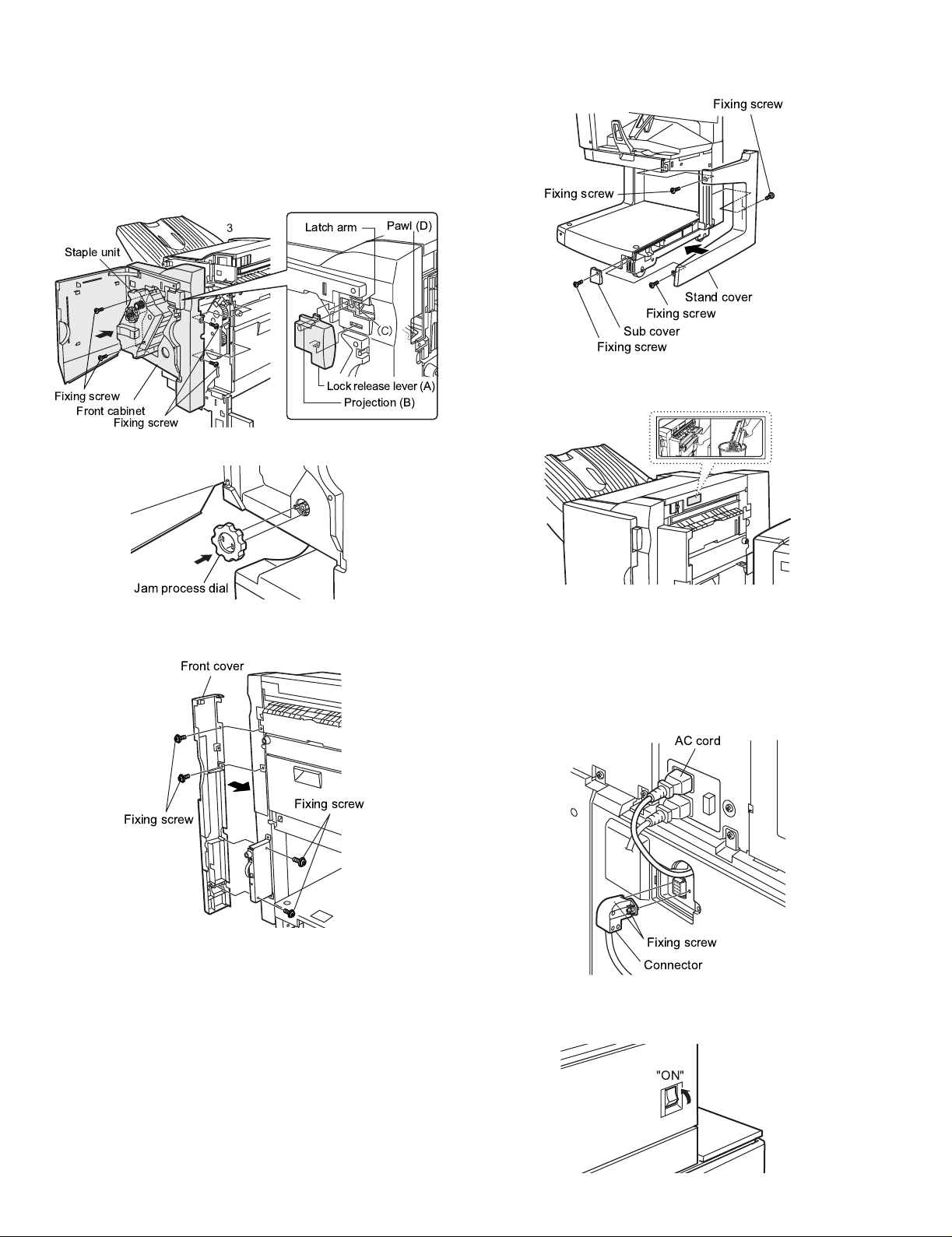
<3>Install the front cabinet to the original position, push the staple unit
into the machine, and fix it with four fixing screws.
* When installing, insert the projection (B) of the lock release lever into
the latch arm hole (C).
* After installation, release the latch and move the lever to check that it
slides smoothly.
* If it does not move smoothly, disengage the pawl on the lower side of
the release lever with a screwdriver (-) and remove the lever. Then
insert is again.
<2>Install the stand cover with three fixing screws, and install the sub
cover with one fixing screw.
Fixing screw
Fixing screw
Latch arm
Lock release lever (A)
Projection (B)
Staple unit
Fixing screw
Front cabinet
3
Fixing screw
<4>Install the jam process dial, and close the front cover.
Jam process dial
8) Install the right front cover of the finisher.
<1>Install the front cover with four fixing screws.
Front cover
Pawl (D)
Stand cover
Fixing screw
Sub cover
Fixing screw
9) Attach the dust box label to the upper cover.
<1>Attach the dust box cover to the position shown in the figure below.
10) Connect the connector to the paper feed desk, and connect the AC
cord of the power unit to the printer.
<1>Connect the connector of the interface harness of the finisher to the
paper feed desk, and tighten the connector fixing screw.
<2>Connect the AC cord of the power unit to the inlet connector of the
printer as shown in the figure.
AC cord
Fixing screw
Fixing screw
Fixing screw
Connector
11) Turn on the main switch of the printer.
<1>Inser t the power plug of the printer to the power outlet.
<2>Turn on the main switch of the printer.
"ON"
AR-FN7/PN1 UNPACKING AND INSTALLATION-6
Page 11

CHAPTER 2
OUTLINE OF OPERATION
COPYRIGHT
#ChapterCover.p65 3/28/01, 12:05 PM2
©
2001 CANON INC. 2001 2001 2001 2001 CANON SADDLE FINISHER G1 REV.0 MAR. 2001
Page 12
CHAPTER 2 OUTLINE OF OPERATION
1 Basic Operations
1.1 Specifications
The finisher serves to deliver sheets coming from its host machine. The mode of delivery
may be non-sort stack, job offset*, or staple delivery.
The saddle unit built into the finisher is used to fold a stack of sheets coming from the fin-
isher unit in half for delivery.
All these operations are controlled by various commands sent by the host machine in ad-
dition to the commands from the finisher controller PCB.
The puncher unit (option) is designed for installation to the pickup assembly of the fin-
isher, and is used to punch holes in sheets coming from the host machine.
The above operations are controlled with various commands from the finisher controller
PCB as well as the commands from the punch controller PCB.
Puncher unit drive
system (puncher unit;
option)
Alignment drive system
Stapler drive system
The position of delivery is shifted to the front/rear for each stack to assist
sorting.
COPYRIGHT
Chap02.p65 3/28/01, 12:07 PM1
©
2001 CANON INC. 2000 2000 2000 2000 CANON SADDLE FINISHER G1 REV.0 MAR. 2001
F02-101-01
Delivery drive system
Control system
Feed drive system
Tray drive system
Saddle unit
drive system
2-1
Page 13
CHAPTER 2 OUTLINE OF OPERATION
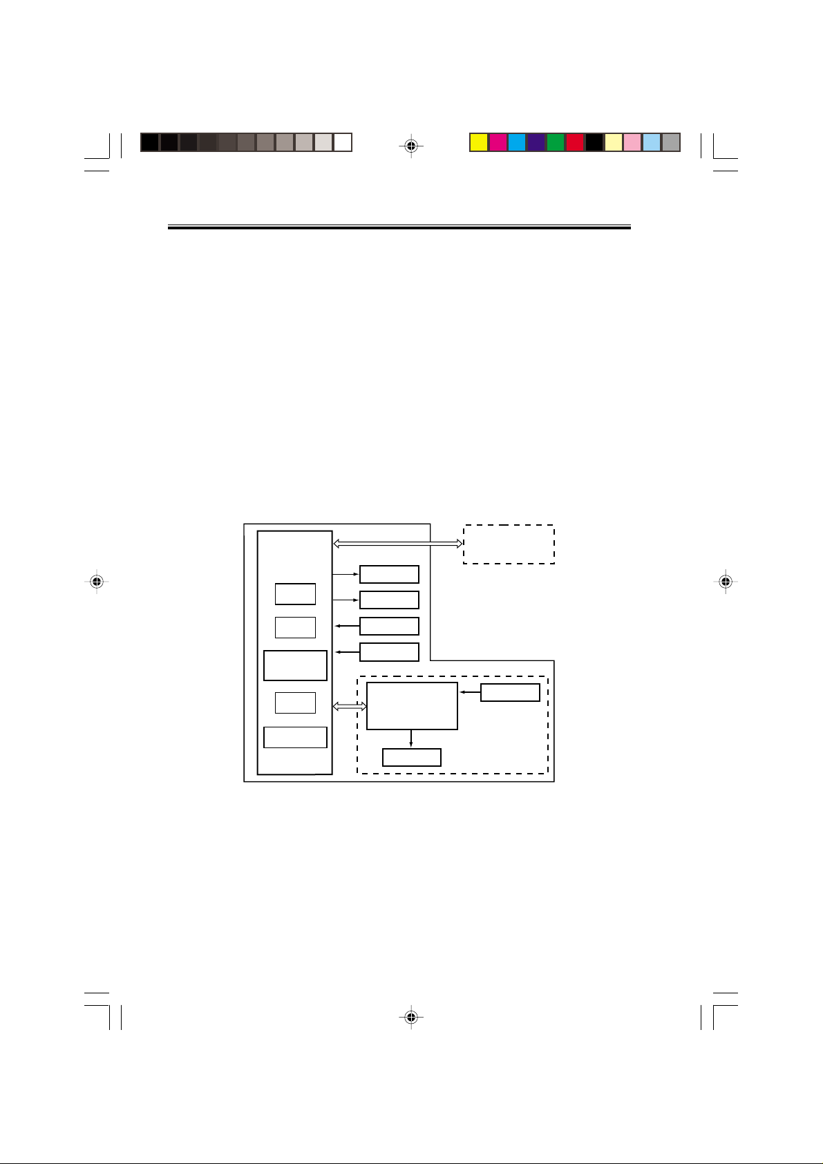
1.2 Outline of the Electrical Circuitry
The sequence of finisher operations is controlled by the finisher controller PCB. The finisher controller PCB is a 16-bit microprocessor (CPU), and is also used for combination
with the host machine (serial).
The finisher controller PCB drive motors and other loads in response to the various commands from the host machine. It also communicates such data as on the states of various
sensors and switches to the host machine by way of the serial communication line.
The ICs mounted to the finisher controller PCB have the following functions:
• IC13 (CPU)
Controls sequence of operations.
• IC12 (EEP-ROM)
Backs up adjustment settings.
• IC6 (EP-ROM)
Stores sequence programs.
F02-102-01 shows the flow of signals between finisher and options controller:
Finisher unit
Finisher
controller
PCB
IC13
CPU
IC12
EEP-ROM
IC11
Communica-
tion IC
IC6
EP-ROM
IC1
Regulator IC
• IC11 (communication IC)
Communicates with the host machine.
• IC1 (regulator IC)
Generates 5 V.
Host machine DC
controller PCB
CPU
Motor
Clutch
Switch
Sensor
Puncher unit (option)
Punch controller
PCB
Motor
Sensor
2-2
Chap02.p65 3/28/01, 12:07 PM2
COPYRIGHT
©
F02-102-01
2001 CANON INC. 2000 2000 2000 2000 CANON SADDLE FINISHER G1 REV.0 MAR. 2001
Page 14
CHAPTER 2 OUTLINE OF OPERATION
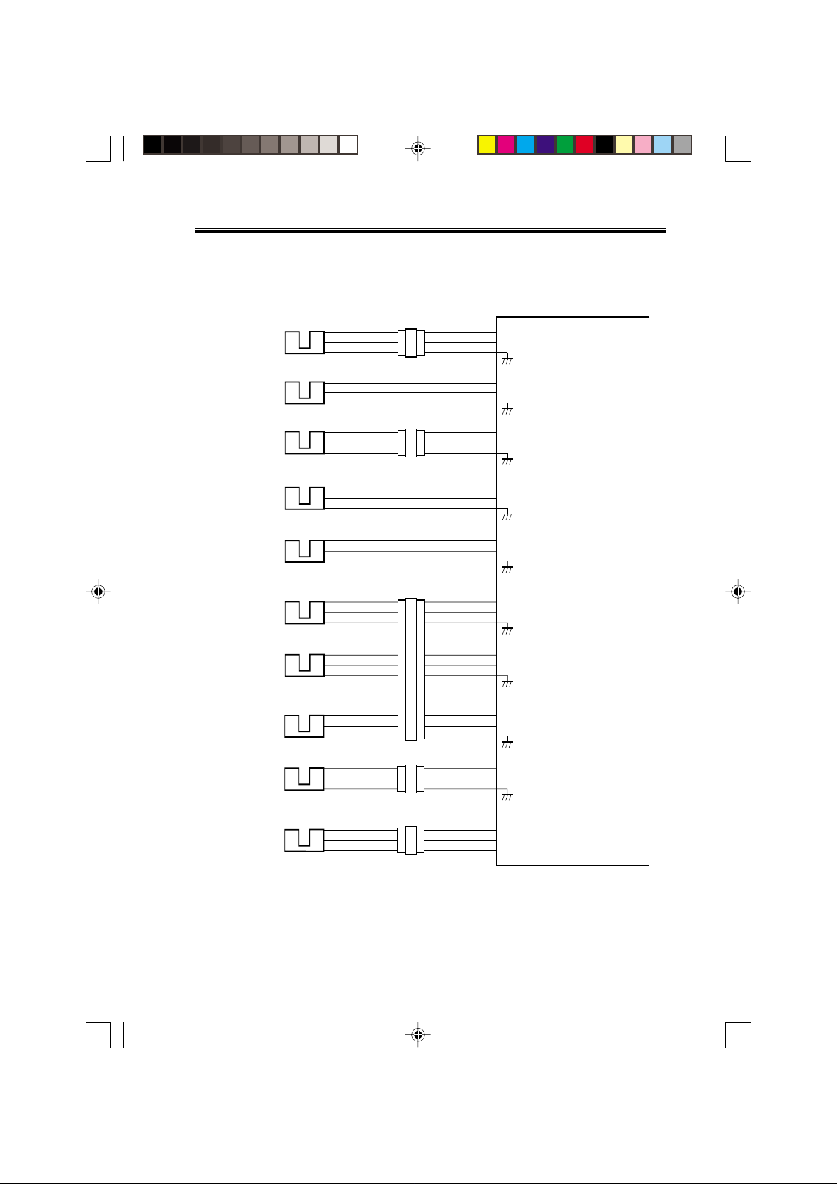
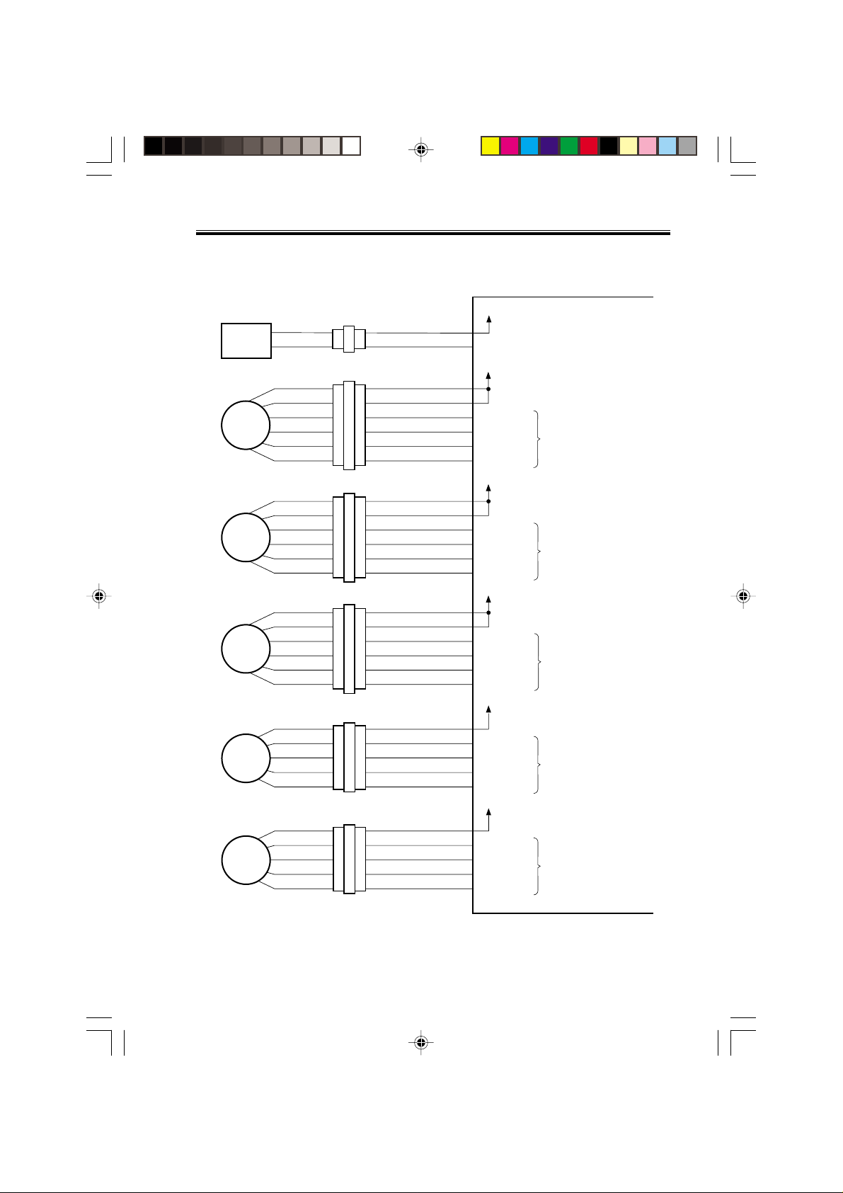
1.3 Inputs to and Outputs from the Finisher Controller PCB
1.3.1 Inputs to the Finisher Controller PCB (1/2)
Finisher controller PCB
Inlet sensor
Paddle home
position sensor
PI1
PI2
CN44-3
CN51-1
CN43-1
-1
-2
-3
-2
CN42-3
-3
-2
-1
-2
CN16-10
-12
-11
CN9-1
-3
-2
+5 V
ENT_S
+5 V
PDL_HP
When the sensor
detects paper, ‘1’ .
When the paddle is at
home position, ‘1’.
Swing guide
home position
sensor
Aligning plate
home position
sensor (front)
Aligning plate
home position
sensor (rear)
Processing
tray sensor
Delivery belt
home position
sensor
Tray paper sensor
Paper surface
sensor
Folding position
sensor
PI3
PI4
PI5
PI6
PI7
PI8
PI9
PI10
CN55-3
CN23-3
CN36-3
CN30-3
CN31-3
CN32-3
CN35-3
CN39-3
CN54-1
-1
-2
-1
-2
-1
-2
CN29-1
-1
-2
-1
-2
-1
-2
CN34-1
-1
-2
CN38-1
-2
-1
CN53-3
-3
-2
CN28-9
-3
-2
-4
-6
-5
-7
-9
-8
CN33-3
-3
-2
CN37-9
-2
-3
CN9-7
CN4
CN5-13
-15
-14
CN5-1
CN5-10
-12
-11
CN16-1
+5 V
-9
BDL_ROL_HP
-8
+5 V
-3
F JOG_HP
-2
+5 V
R JOG_HP
+5 V
-3
ADJ_TRAY_S
-2
-4
+5 V
-6
EJCT_BLT_HP
-5
-7
+5 V
-9
TRY_EMPS
-8
+5 V
LVL_S
+5 V
-2
BIND_P
-3
BIND_L
-1
-2
-7
-8
-6
-4
-5
-3
-1
-2
-1
-2
-8
-7
When the swing guide
is at home position, ‘1’.
When the aligning
plate (front) is at
home position, ‘1’.
When the aligning
plate (rear) is at
home position, ‘1’.
When the sensor
detects paper, ‘1’.
When the delivery belt
is at home position, ‘1’.
When paper is present
on the tray, ‘1’.
When the paper
surface is detected,
‘1’.
When paper is
detected, ‘0’.
When LED is lit, ‘1’.
COPYRIGHT
Chap02.p65 3/28/01, 12:07 PM3
©
2001 CANON INC. 2000 2000 2000 2000 CANON SADDLE FINISHER G1 REV.0 MAR. 2001
F02-103-01
2-3
Page 15
CHAPTER 2 OUTLINE OF OPERATION
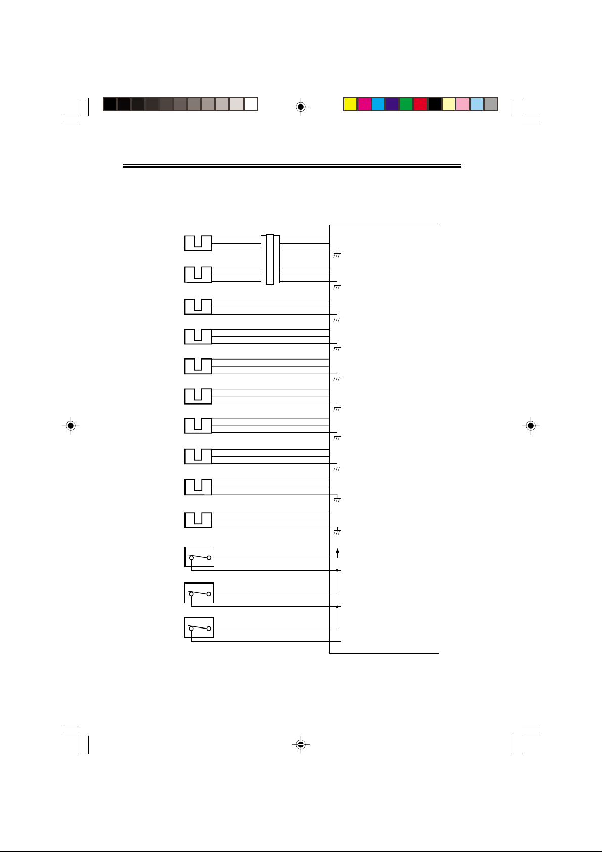
1.3.2 Inputs to the Finisher Controller PCB (2/2)
Folding home
position sensor
Stack feed roller
(upper) home
position sensor
Bind tray sensor
Staple/fold motor
clock sensor
Shift upper limit
sensor
Shift lower limit
sensor
Shift motor clock
sensor
Front door sensor
Upper cover sensor
PI11
PI12
PI13
PI14
PI15
PI16
PI17
PI22
PI23
CN40-3
CN41-3
CN47-3
CN52-1
CN50-3
CN49-3
CN48-3
CN25-3
CN24-3
-1
-2
-1
-2
-1
-2
-2
-3
-1
-2
-1
-2
-1
-2
-1
-2
-1
-2
CN38-4
CN37-6
-6
-5
-7
-9
-8
-4
-5
-3
-1
-2
CN15-10
CN16-4
CN15-1
CN9-6
-12
-11
CN15-7
CN15-4
CN4-7
CN4-4
-6
-5
-7
-9
-8
-3
-2
-5
-4
-9
-8
-6
-5
-9
-8
-6
-5
Finisher controller PCB
+5 V
BIND_HP
+5 V
BIND_ROL_HP
+5 V
BIND_EMPS
+5 V
BIND_CLK
+5 V
SIFT_UPLMT
+5 V
SIFT_DNLMT
+5 V
SIFT_CLK
+5 V
FDOOR_S
+5 V
TOPCOV_S
When at folding home position, ‘0’.
When the stack feed roller
(upper) is at home position, ‘1’.
When the sensor
detects paper, ‘1’.
When the staple/fold motor is
rotating, alternates between
‘1’ and ‘0’.
When the tray is at the
upper limit, ‘1’.
When the tray is at the
lower limit, ‘1’.
While the shift motor
is rotating, alternates
between ‘1’ and ‘0’.
When the front door
is open, ‘1’.
When the upper cover
is open, ‘1’.
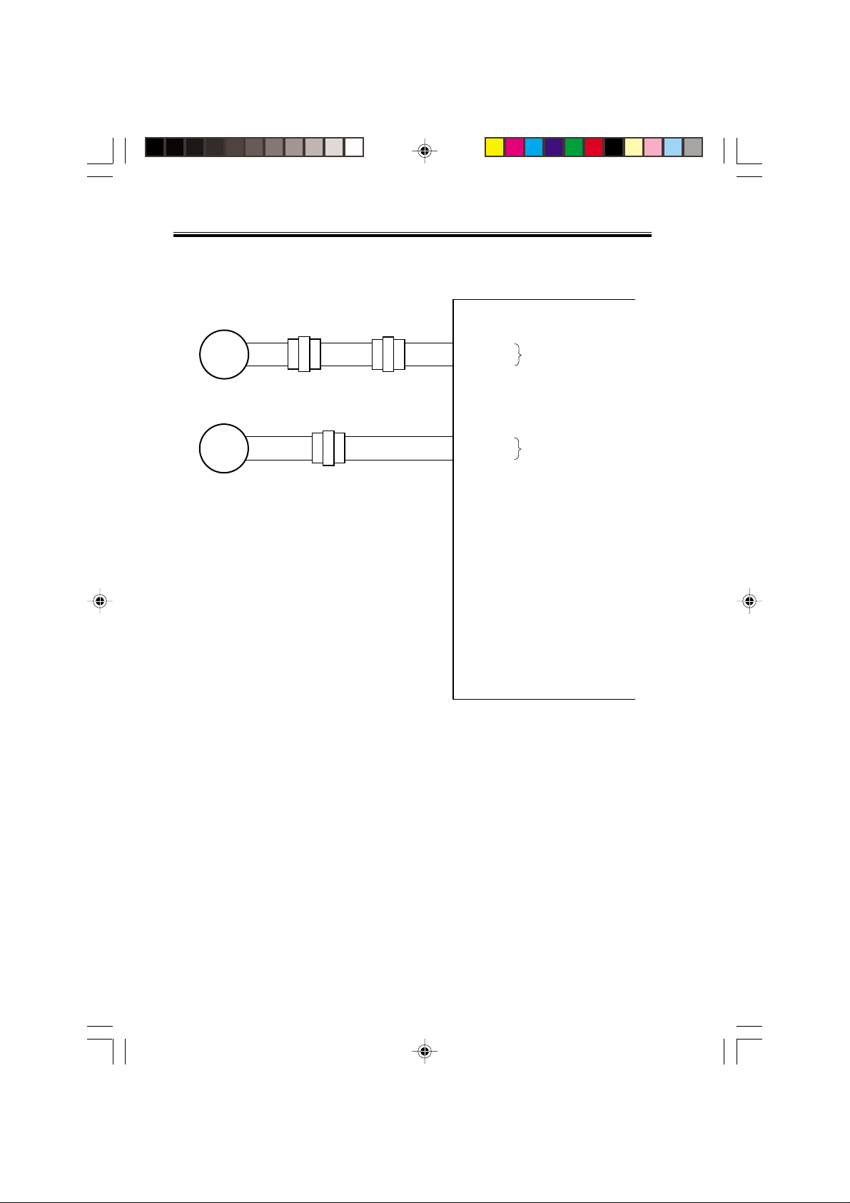
PI24
Full stack sensor
Joint switch
Front door switch
Stapler safety
switch
2-4
Chap02.p65 3/28/01, 12:07 PM4
CN73-3
MS2
N. O.
CN69-2
MS1
N. O.
CN68-2
MS3
N. O.
CN66-2
COPYRIGHT
©
CN19-1
+5 V
CN8-6
CN8-4
CN8-2
-3
-2
-5
-3
-1
PAPER_F
+24 VP
JOINT SW
FRONT SW
STPLSAFE SW
-1
-2
-1
-1
-1
When the paper is
full, ‘1’.
When connected to
the host machine, ‘1’.
When the front
door is closed, ‘1’.
When the swing
guide is closed, ‘1’.
F02-103-02
2001 CANON INC. 2000 2000 2000 2000 CANON SADDLE FINISHER G1 REV.0 MAR. 2001
Page 16
CHAPTER 2 OUTLINE OF OPERATION
1.3.3 Outputs from the Finisher Controller PCB (1/2)
Finisher controller PCB
Binding clutch
CL1
Feed motor
M1
Paddle motor
M2
Delivery motor
M3
Alignment motor
(front)
M4
Alignment motor
(rear)
M5
CN63-1
CN65-1
-1
-2
-6
-5
-4
-3
-2
-1
-6
-5
-4
-3
-2
-1
-6
-5
-4
-3
-2
-1
-2
-3
-4
-5
-2
-3
-4
-5
CN72
CN56
CN57
CN59
-2
-1
-1
-2
-3
-4
-5
-6
-1
-2
-3
-4
-5
-6
-1
-2
-3
-4
-5
-6
CN62-5
CN64-5
CN18-1
CN10-1
CN10-7
CN13-1
CN3-1
-4
-3
-2
-1
CN3-6
-4
-3
-2
-1
-2
B_CLU
-2
-3
FEEDMTR_A
-4
FEEDMTR_*A
-5
FEEDMTR_B
-6
FEEDMTR_*B
-8
-9
PDLMTR_A
-10
PDLMTR_*A
-11
PDLMTR_B
-12
PDLMTR_*B
-2
-3
EJCTMTR_A
-4
EJCTMTR_*A
-5
EJCTMTR_B
-6
EJCTMTR_*B
-2
FJOGMTR_A
-3
FJOGMTR_*A
-4
FJOGMTR_B
-5
FJOGMTR_*B
-7
RJOGMTR_A
-8
RJOGMTR_*A
-9
RJOGMTR_B
-10
RJOGMTR_*B
+24 V
When the drive is transmitted,
‘1’.
+24 V
Switches between ‘1’ and
‘0’ according to the
direction of motor rotation.
+24 V
Switches between ‘1’ and
‘0’ according to the
direction of motor rotation.
+24 V
Switches between ‘1’ and
‘0’ according to the
direction of motor rotation.
+24 V
Switches between ‘1’ and
‘0’ according to the
direction of motor rotation.
+24 V
Switches between ‘1’ and
‘0’ according to the
direction of motor rotation.
COPYRIGHT
Chap02.p65 3/28/01, 12:07 PM5
©
2001 CANON INC. 2000 2000 2000 2000 CANON SADDLE FINISHER G1 REV.0 MAR. 2001
F02-103-03
2-5
Page 17
CHAPTER 2 OUTLINE OF OPERATION
1.3.4 Outputs from the Finisher Controller PCB (2/2)
Shift motor
M6
Staple/fold motor
M7
-2
-1
-2
-1
CN70
-2
-1
CN71
-2
-1
-2
-1
CN70
CN6-1
-2
-1
CN6-3
SIFTMTR_1
-2
SIFTMTR_0
BINDMTR_1
-4
BINDMTR_0
Finisher controller PCB
Switches between ‘+’ and
‘–’ according to the
direction of motor rotation.
Switches between ‘+’ and
‘–’ according to the
direction of motor rotation.
2-6
Chap02.p65 3/28/01, 12:07 PM6
COPYRIGHT
©
F02-103-04
2001 CANON INC. 2000 2000 2000 2000 CANON SADDLE FINISHER G1 REV.0 MAR. 2001
Page 18
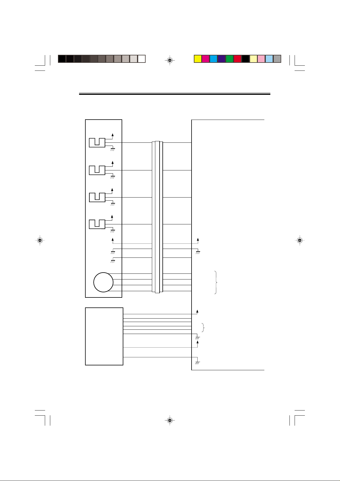
CHAPTER 2 OUTLINE OF OPERATION
1.3.5 Inputs to and Outputs from the Finisher Controller
Stapler unit
Slide home
position sensor
PI18
Staple home
position sensor
PI19
Staple empty
sensor
PI20
Staple top
position sensor
PI21
Slide motor
M8
+5 V
+5 V
+5 V
+5 V
+5 V
CN72-5
CN72-4
CN72-3
CN72-2
CN72-6
CN72-1
CN72-7
CN72-10
CN72-11
CN72-12
CN72-13
CN72A-5
CN72A-4
CN72A-3
CN72A-2
CN72A-6
CN72A-1
CN72A-7
CN72B-5
CN72B-4
CN72B-3
CN72B-2
CN72A-5
CN72A-4
CN72A-3
CN72A-2
CN72A-6
CN72A-1
CN72A-7
CN72B-5
CN72B-4
CN72B-3
CN72B-2
CN11-3
CN11-4
CN11-5
CN11-6
CN11-2
CN11-7
CN11-1
CN7-3
CN7-4
CN7-5
CN7-6
Finisher controller PCB
SLID_HP
STPL_HP
HOOK_S
SELF_P
+5 V
STPL_CNCT
SLIDMTR_A
SLIDMTR_*A
SLIDMTR_B
SLIDMTR_*B
When the stapler is at home
position, ‘1’.
When the stapler is at
stapling home position, ‘0’.
When the cartridge has
staples, ‘0’.
When the staple is at top
the stapler, ‘0’.
When the stapler is
connected, ‘0’.
Switches between ‘1’ and
‘0’ according to the direction
of motor rotation.
Host
machine
COPYRIGHT
Chap02.p65 3/28/01, 12:07 PM7
©
2001 CANON INC. 2000 2000 2000 2000 CANON SADDLE FINISHER G1 REV.0 MAR. 2001
CN2-1
CN1-1
F02-103-05
+24 V
-3
GND
-4
GND
-5
TXD
-7
-6
-2
Communication line
RXD
+24 V
2-7
Page 19
CHAPTER 2 OUTLINE OF OPERATION
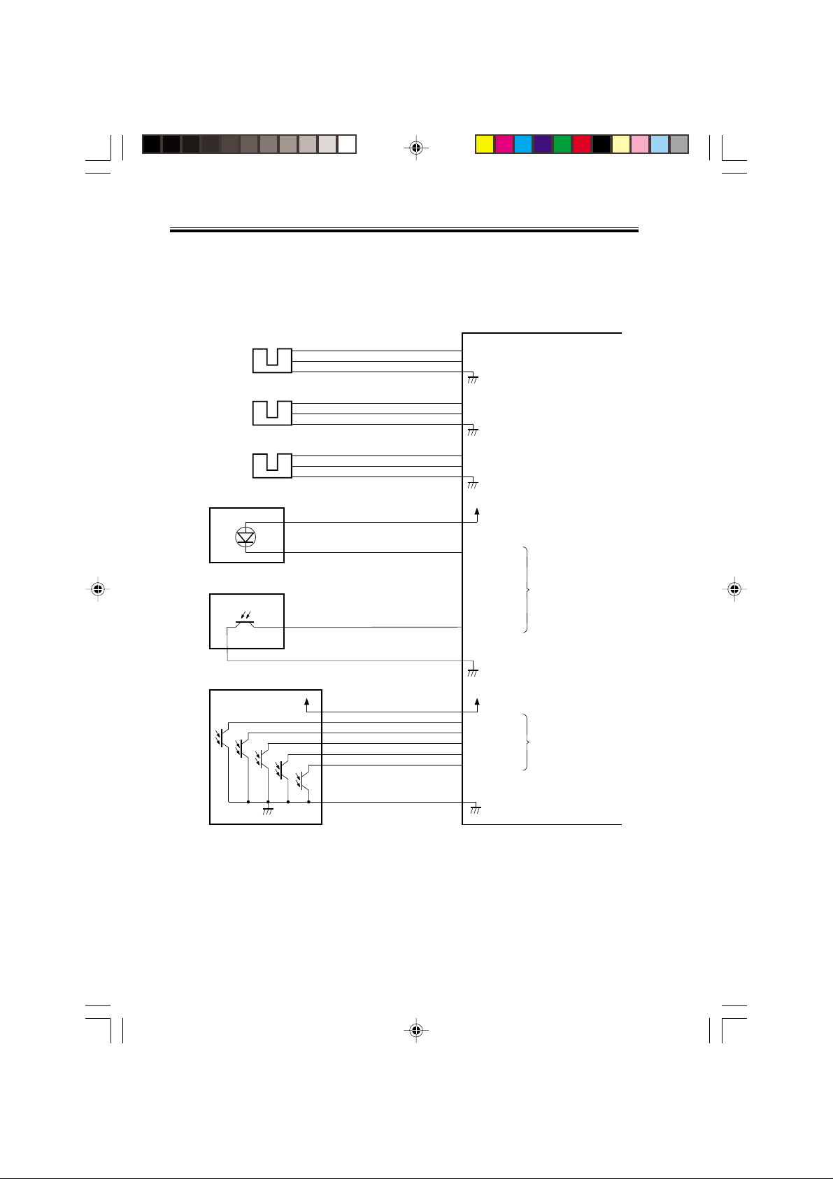
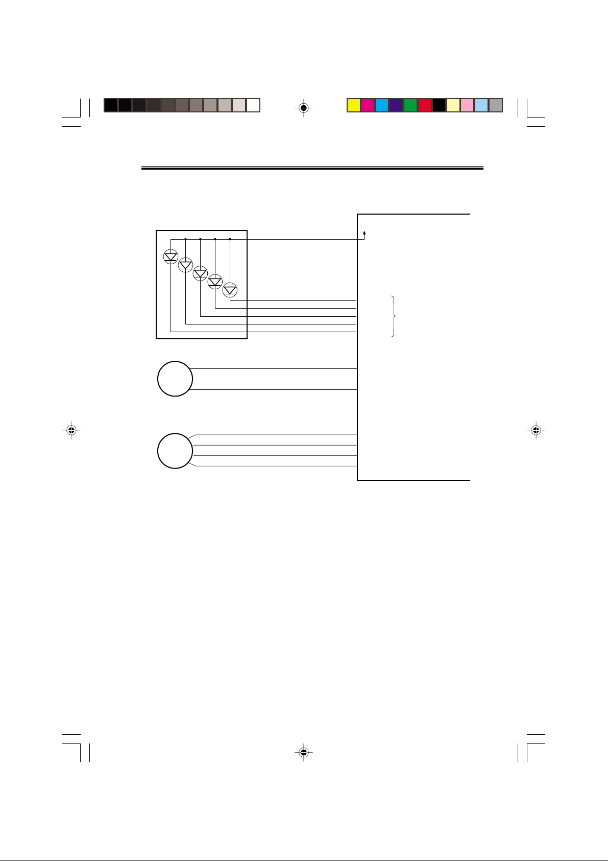
1.4 Inputs to and Outputs from the Punch Controller PCB
(option)
1.4.1 Inputs to and Outputs from the Punch Controller PCB
Punch controller PCB
PI1P
Punch home
position sensor
J2008-3
-1
-2
J1006-4
-6
-5
+5 V
PUNCH
When the hole puncher is
at home position, ‘0’.
Horizontal
registration
home position
sensor
Punch motor
clock sensor
Waste full LED PCB
LED121
Waste full photosensor PCB
PT131
PT1
PI2P
PI3P
Photosensor PCB
PT2
PT3
PT4
J2007-3
J2009-3
+5 V
PT5
J1006-1
J1006-7
J1005-1
J1005-3
-11
-10
-13
-3
-2
-9
-8
-2
4
-9
-8
-7
+5 V
SLIDE
+5 V
CLOCK
+5V
DUSTLED
DUSTPTR
+5 V
SREG1*
SREG2*
SREG3*
SREG4*
PAEND*
-1
-2
-1
-2
J1007-12
When the punch slide
unit is at home position,
‘1’.
While the punch motor
is rotating, alternates
between ‘0’ and ‘1’.
When the light is
blocked, ‘0’.
When paper is
detected, ‘0’.
2-8
Chap02.p65 3/28/01, 12:07 PM8
COPYRIGHT
©
F02-104-01
2001 CANON INC. 2000 2000 2000 2000 CANON SADDLE FINISHER G1 REV.0 MAR. 2001
Page 20
CHAPTER 2 OUTLINE OF OPERATION
1.4.2 Outputs from the Punch Controller PCB
LED PCB
LED5
Punch motor
M1P
Horizontal
registration
motor
M2P
LED4
LED3
LED2
LED1
J1007-6
J1002-1
J1001-1
-1
-5
-4
-3
-2
-2
-2
-3
-4
+5V
LEDON5
LEDON4
LEDON3
LEDON2
LEDON1
A
B
A*
B*
Punch controller PCB
When ‘1’, LED goes ON.
Switches between ‘+’
and ‘–’ according to
the direction of motor
rotation.
Switches the pulse
signals according to
the rotation of the motor.
COPYRIGHT
Chap02.p65 3/28/01, 12:07 PM9
©
2001 CANON INC. 2000 2000 2000 2000 CANON SADDLE FINISHER G1 REV.0 MAR. 2001
F02-104-02
2-9
Page 21

CHAPTER 2 OUTLINE OF OPERATION
2 Feed/Drive System
2.1 Outline
The machine performs the following in response to the commands coming from its host
machine on the sheets arriving from the host machine for delivery: simple stacking, job offset, and stapling or folding (in two).
If a punch unit (option) is installed, the sheets are pouched and delivered to the delivery
tray.
Sheets may be delivered in either of five ways (including one for the puncher unit):
Delivery
method
delivery
PunchingNormal
StitchingSaddle delivery
F02-201-01
Simple stacking
Job offset
Stapling Front 1-point stapling
Rear 1-point stapling
Middle 2-point stapling
Middle 2-point stapling
2-10
Chap02.p65 3/28/01, 12:07 PM10
COPYRIGHT
©
2001 CANON INC. 2000 2000 2000 2000 CANON SADDLE FINISHER G1 REV.0 MAR. 2001
Page 22
CHAPTER 2 OUTLINE OF OPERATION
2.1.1 Normal Delivery
a. Simple Stacking
The machine pulls in the sheet once to the processing tray and then delivers it to the deliv-
ery tray.
COPYRIGHT
Chap02.p65 3/28/01, 12:07 PM11
©
2001 CANON INC. 2000 2000 2000 2000 CANON SADDLE FINISHER G1 REV.0 MAR. 2001
Tray
Paper
F02-201-02
2-11
Page 23
CHAPTER 2 OUTLINE OF OPERATION
b. Job Offset
The machine pulls the sheet once to the processing tray. It then moves the sheet to the
front or the rear using the aligning plate. When it has deposited a specific number of sheets,
it delivers them in the form of a aligning plane. When the number of sheets stacked on the
processing tray reaches a specified value, the sheets are delivered in a form of a stack. Even
if the specified value is not reached, stacked sheets are temporarily delivered when 10 sheets
of large-size paper (300 mm or longer) or 30 sheets of small-size paper (299 mm or shorter)
have been stacked. (5- and STMT-sizes: 10 sheets)
Results of offset delivery (4 jobs)
3rd set
1st set
(direction of delivery)
2-12
Chap02.p65 3/28/01, 12:07 PM12
COPYRIGHT
©
2001 CANON INC. 2000 2000 2000 2000 CANON SADDLE FINISHER G1 REV.0 MAR. 2001
4th set
2nd set
F02-201-03
Page 24
CHAPTER 2 OUTLINE OF OPERATION
c. Stapling
The machine stacks sheets coming from its host machine on the processing tray. When
the number of sheets stacked on the processing tray reaches a specified value, the finisher
staples them delivers the stapled stack to the delivery tray.
COPYRIGHT
Chap02.p65 3/28/01, 12:07 PM13
©
2001 CANON INC. 2000 2000 2000 2000 CANON SADDLE FINISHER G1 REV.0 MAR. 2001
F02-201-04
2-13
Page 25
CHAPTER 2 OUTLINE OF OPERATION
d. Saddle Deliver y
The machine deposits a stack of sheets on the processing tray, staples it (middle 2-point),
and then moves it to the saddle unit. The saddle unit folds the stack in two, and delivers it to
the bind tray.
2-14
Chap02.p65 3/28/01, 12:07 PM14
COPYRIGHT
©
2001 CANON INC. 2000 2000 2000 2000 CANON SADDLE FINISHER G1 REV.0 MAR. 2001
F02-201-05
Page 26

CHAPTER 2 OUTLINE OF OPERATION
2.2 Feed/Delivery
2.2.1 Outline
The machine forwards the sheets coming from its host machine to the delivery tray, processing tray, or saddle unit according to the type of delivery used. The sheets forwarded to
the processing tray or the saddle unit are offset, stapled, or folded.
F02-202-01 shows the motors that are associated with moving and aligning sheets. These
motors are controlled (rotated clockwise or counterclockwise) by the microprocessor (CPU)
on the finisher controller PCB.
The paper path is equipped with the sensors shown in T02-202-02 used to monitor the arrival or passage of sheets.
If a sheet fails to arrive at or move past a specific sensor within a specific period of time,
the finisher controller will assume a jam, and stops the ongoing operation and, at the same
time, communicates the presence of a jam to the host machine.
Connector on finisher
Notation
M1
M2
M3
M4
M5
M7
Name
Feed motor
Paddle motor
Delivery motor
Alignment plate motor
(front)
Alignment plate motor
(rear)
Staple/fold motor
Description
Stepping motor
Stepping motor
Stepping motor
Stepping motor
Stepping motor
Brush DC motor
controller PCB
CN10
CN10
CN13
CN3
CN3
CN6
COPYRIGHT
Chap02.p65 3/28/01, 12:07 PM15
©
2001 CANON INC. 2000 2000 2000 2000 CANON SADDLE FINISHER G1 REV.0 MAR. 2001
T02-202-01
2-15
Page 27
Chap02.p65 3/28/01, 12:07 PM16
2-16
COPYRIGHT
©
2001 CANON INC. 2000 2000 2000 2000 CANON SADDLE FINISHER G1 REV.0 MAR. 2001
Shift motor drive signal SIFTMTR
Delivery motor drive signal EJCTMTR
Slide motor drive signal SLIDMTR
Finisher controller PCB (2/2)
F02-202-01
Staple/fold motor drive signal BINDMTR
Staple/fold motor clock detect signal
BIND_CLK
M7
PI14
M6
M8
M3
CL
Alignment plate motor
(front) drive signal FJOGMTR
M4
Alignment plate motor
(rear) drive signal RJOGMTR
M5
Paddle motor
M2
M1
drive signal PDLMTR
Bind clutch drive signal B_CLU
Feed motor
drive signal FEEDMTR
CHAPTER 2 OUTLINE OF OPERATION
Finisher controller PCB (1/2)
Page 28
CHAPTER 2 OUTLINE OF OPERATION
Finisher controller PCB
Inlet paper detect signal ENT_P
Fold position paper detect signal BIND_P
PI1
PI10
Notation
PI1
PI10
COPYRIGHT
Chap02.p65 3/28/01, 12:07 PM17
©
2001 CANON INC. 2000 2000 2000 2000 CANON SADDLE FINISHER G1 REV.0 MAR. 2001
Name
Inlet sensor
Fold position sensor
F02-202-02
Description
Photointerrupter
Photointerrupter
T02-202-02
Connector on finisher
controller PCB
CN16
CN16
2-17
Page 29

CHAPTER 2 OUTLINE OF OPERATION
2.3 Job Offset
2.3.1 Outline
"Job offset" refers to the operation by which the machine delivers a set of sheets with
them pulled forward or backward for sorting.
Switching between the forward and backward directions is made using an aligning plate
(front) and an aligning plate (rear).
The sheet coming between the delivery rollers is fed onto the processing tray and then fed
toward the stopper by the paddle.
A swing guide is at the up position while a sheet is being pulled onto the processing tray
or during alignment. It is at the down position during stack feeding, stack delivery, or stapling.
At power-on, the finisher controller PCB drives the aligning plate (front) motor (M4) and
the aligning plate (rear) motor (M5) to return the two aligning plates to their home positions.
Sensor
Aligning plate (front)
home position sensor
Aligning plate (rear)
home position sensor
Swing guide home position sensor
Paddle home position
sensor
Symbol
PI4
PI5
PI3
PI2
Connector
CN4-3
CN5-15
CN9-9
CN9-3
T02-203-01
Function
Drives the aligning
plate (front)
Drives the aligning
plate (rear)
Drives the swing
guide drive.
Drives the paddle
(feeds paper).
Motor
Aligning plate
(front) motor
Aligning plate
(rear) motor
Paddle motor
Paddle motor
Simbol
M4
M5
M2
M2
2-18
Chap02.p65 3/28/01, 12:07 PM18
COPYRIGHT
©
2001 CANON INC. 2000 2000 2000 2000 CANON SADDLE FINISHER G1 REV.0 MAR. 2001
Page 30
CHAPTER 2 OUTLINE OF OPERATION
Alignment plate (front)
motor (M4)
Aligning plate
(front)
(Front)
Aligning plate (front) home position sensor (PI4)
Light-shielding plate
Aligning plate (rear)
Alignment plate (rear)
motor (M5)
F02-203-01
Aligning plate (rear)
home position sensor (PI5)
Light-shielding plate
Paper
COPYRIGHT
Chap02.p65 3/28/01, 12:07 PM19
©
2001 CANON INC. 2000 2000 2000 2000 CANON SADDLE FINISHER G1 REV.0 MAR. 2001
2-19
Page 31

CHAPTER 2 OUTLINE OF OPERATION
2.3.2 Processing Tray Paper Stacking Operation
A sheet coming between the delivery rollers is fed onto the processing tray. Then, the
paddle taps on the sheet surface twice (once for the second and subsequent sheets) to locate
the sheet against the processing tray stopper.
Paper
Aligning plate
Delivery belt
T02-203-02
Paddle
Stack delivery roller (upper)
Swing guide
Processing tray stopper
Stack delivery roller (lower)
2-20
Chap02.p65 3/28/01, 12:07 PM20
COPYRIGHT
©
2001 CANON INC. 2000 2000 2000 2000 CANON SADDLE FINISHER G1 REV.0 MAR. 2001
Page 32

CHAPTER 2 OUTLINE OF OPERATION
2.3.3 Offset Operation
Each sheet is pulled forward or backward using the aligning plate (front) and the aligning
plate (rear).
The offset operation is performed each time a sheet is pulled onto the processing tray.
Aligning plate (rear)
Sheet to be offset
Tray
Aligning plate (front)
F02-203-03 Offsetting in the forward direction
Aligning plate (rear)
Sheet to be offset
Tray
Aligning plate (front)
F02-203-04 Offsetting in the backward direction
COPYRIGHT
Chap02.p65 3/28/01, 12:07 PM21
©
2001 CANON INC. 2000 2000 2000 2000 CANON SADDLE FINISHER G1 REV.0 MAR. 2001
2-21
Page 33

CHAPTER 2 OUTLINE OF OPERATION
2.3.4 Stack Delivery Operation
Stack delivery takes place when 10 sheets of large-size paper or 30 sheets of small-size
paper (A5- and STMT-sizes: 10 sheets) have been stacked on the processing tray with them
offset in either direction.
The paddle motor rotates and the swing guide descends to hold the paper stack between
the upper and lower stack delivery rollers. The delivery motor rotates in the forward direction to rotate the delivery rollers, feeding the paper stack in the delivery direction. The delivery belt home position sensor is turned OFF. The delivery motor is driven a specified number of pulses, causing the swing guide to ascend. Next, the paper delivery motor is driven.
Next, the delivery motor is driven to deliver the paper stack with the nails of the delivery
belt that rotates in sync with the stack delivery rollers.
Swing guide
F02-203-05
Job offset sequence
Inlet sensor (PI1)
Processing tray sensor
(PI6)
Feed motor (M1)
Delivery motor (M3)
Delivery belt home
position sensor (PI7)
Paddle motor (M2)
Paddle home position
sensor (PI2)
Swing guide home
position sensor (PI3)
Stapler safety switch
(MS3)
Alignment motor (front)
(M4)
Aligning plate home position
sensor (front) (PI4)
Alignment motor (rear)
(M5)
Aligning plate home position
sensor (rear) (PI5)
2-22
Chap02.p65 3/28/01, 12:18 PM22
COPYRIGHT
©
2001 CANON INC. 2000 2000 2000 2000 CANON SADDLE FINISHER G1 REV.0 MAR. 2001
Start signal
Host machine delivery signal
360msec
F02-203-06
360msec 360msec
60msec
360msec
30msec
220msec
CW rotation CCW rotation
Page 34

CHAPTER 2 OUTLINE OF OPERATION
3. Stapling Operation
3.1 Outline
Staple operation is performed to staple a specified sheets of paper using a stapler unit.
The stapling position depends on the staple mode and paper size.
When the machine starts immediately after power-on, the finisher controller PCB drives
the slide motor (M8) to return the stapler unit to the home position. The stapler unit starts
moving toward the front of the stapler frame. It stops when the slide home position sensor
(PI18) on the slide PCB located under the stapler unit. Next, the slide motor is driven a
specified number of pulses. The stapler unit moves to rear standby position at the back of
the machine, entering the standby state.
Sensor
Slide home position
sensor
Staple home position
sensor
Staple empty sensor
Staple top position
sensor
Simbol
PI18
PI19
PI20
PI21
Connector
CN11-3
CN11-4
CN11-5
CN11-6
Detects the home position for the
stapler moving back and forth.
Detects the home position for the
stapling operation
Detects presence or absence of
staples in the cartridge.
Detects the staple top position.
Function
Function Motor Symbol Remarks
Moves the stapler. Slide motor M8 –
Performs stapling operation. Staple/fold motor M7 –
T02-301-01
Remarks
–
In the stapler
In the stapler
In the stapler
COPYRIGHT
Chap02.p65 3/28/01, 12:07 PM23
©
2001 CANON INC. 2000 2000 2000 2000 CANON SADDLE FINISHER G1 REV.0 MAR. 2001
2-23
Page 35

CHAPTER 2 OUTLINE OF OPERATION
Stapler
Slide motor
(M8)
Paper stack
(Deliver direction)
Light-shielding plate
Slide home position sensor (PI18)
F02-301-01
2-24
Chap02.p65 3/28/01, 12:07 PM24
COPYRIGHT
©
2001 CANON INC. 2000 2000 2000 2000 CANON SADDLE FINISHER G1 REV.0 MAR. 2001
Page 36

CHAPTER 2 OUTLINE OF OPERATION
3.2 Stapling Operation
When stacking and alignment of paper on the processing tray are complete, the finisher
controller PCB drives the paddle motor (M2) in the reverse direction and lowers the swing
guide. When the swing guide descends, the paper stack is sandwiched between the upper
and lower stack delivery rollers.
The finisher controller PCB moves the stapler for stapling according to the specified stapling position (when rear 1-point stapling is specified, the stapler does not move but it
staples at the standby position). As the stapler moves forward, the processing tray stopper is
folded forward.
Paper stack
Swing guide
Stack delivery roller (upper)
Processing tray stopper
Delivery tray
Stack
delivery
roller
(lower)
Stapler
COPYRIGHT
Chap02.p65 3/28/01, 12:07 PM25
©
2001 CANON INC. 2000 2000 2000 2000 CANON SADDLE FINISHER G1 REV.0 MAR. 2001
F02-302-01
2-25
Page 37

CHAPTER 2 OUTLINE OF OPERATION
Paddle motor (M2)
Staple safety switch
(MS3)
Swing guide
Stack delivery roller
(upper)
Swing guide home
position sensor (PI3)
Light-shielding plate
Stack delivery roller
(lower)
2-26
Chap02.p65 3/28/01, 12:07 PM26
COPYRIGHT
©
2001 CANON INC. 2000 2000 2000 2000 CANON SADDLE FINISHER G1 REV.0 MAR. 2001
F02-302-02
Page 38

CHAPTER 2 OUTLINE OF OPERATION
3.3 Delivery Operation after Stapling
When stapling is complete, the finisher controller PCB drives the deliver motor in the forward direction to feed the paper stack (sandwiched between the stack delivery rollers) in the
delivery direction. The delivery belt home position sensor is turned OFF. The delivery motor is driven a specified number of pulses, causing the swing guide to ascend. At the same
time, the slide motor is driven to return the stapler back to the standby position, followed by
driving of the delivery motor. Then, the paper stack is delivered with the nails of the delivery belt that rotates in sync with the stack delivery rollers.
Paper stack
Swing guide
Delivery tray
Delivery belt
Stack delivery
roller (lower)
F02-303-01
Stapler
COPYRIGHT
Chap02.p65 3/28/01, 12:07 PM27
©
2001 CANON INC. 2000 2000 2000 2000 CANON SADDLE FINISHER G1 REV.0 MAR. 2001
2-27
Page 39

CHAPTER 2 OUTLINE OF OPERATION
Paddle motor (M2)
Staple safety
switch (MS3)
Swing guide
Swing guide
home position sensor (PI3)
Light-shielding plate
Stack delivery roller (lower)
2-28
Chap02.p65 3/28/01, 12:07 PM28
COPYRIGHT
©
2001 CANON INC. 2000 2000 2000 2000 CANON SADDLE FINISHER G1 REV.0 MAR. 2001
Stack delivery roller (upper)
F02-303-02
Page 40

CHAPTER 2 OUTLINE OF OPERATION
3.4 Stapler Unit
The staple/fold motor (M7) is used to perform stapling operation. This motor rotates the
cam one turn for stapling. The home position of this cam is detected by the staple home position sensor (PI19).
The staple/fold motor is rotated in the forward or reverse direction under the control of
the macro computer (IC13) on the finisher controller PCB.
When the staple home position sensor is OFF, the finisher controller PCB rotates the
staple/fold motor in the forward direction until the sensor turns ON, allowing the staple cam
to the original position.
The staple empty sensor (PI20) is used to detect presence/absence of a staple cartridge in
the machine and presence/absence of staples in the cartridge.
The stale top position sensor (PI21) is used to determine whether staples are pushed up to
the top of the staple cartridge.
The finisher controller circuit does not drive the staple/fold motor (M7) unless the staple
safety switch (MS3) is ON (the swing guide is close). This assures safety in case where you
happen to put your finger in the stapler.
COPYRIGHT
Chap02.p65 3/28/01, 12:07 PM29
©
2001 CANON INC. 2000 2000 2000 2000 CANON SADDLE FINISHER G1 REV.0 MAR. 2001
2-29
Page 41

CHAPTER 2 OUTLINE OF OPERATION
F02-304-01
Staple home position detect signal
2-30
Chap02.p65 3/28/01, 12:07 PM30
COPYRIGHT
©
2001 CANON INC. 2000 2000 2000 2000 CANON SADDLE FINISHER G1 REV.0 MAR. 2001
Staple top position detect signal
Staple empty detect signal
Finisher controller PCB
F02-304-02
M7
Staple/hold motor drive signal
Page 42

CHAPTER 2 OUTLINE OF OPERATION
3.4.1 Stapler Movement Controller
The stapler unit is moved by the slide motor (M8). Its home position is detected by the
slide home position sensor (PI18). The stapler waits at the back irrespective of the staple
mode and paper size. After paper has been stacked on the processing tray, the stapler is
moved to the specified stapling position in response to the stapling command from the host
machine.
F02-304-03 shows the standby position of the stapler and the stapling position depending
on the staple mode.
a. Front 1-point stapling
The stapler waits at the back. The stapler moves to and returns from the stapling position
for each stapling operation.
Standby position
Stapler
Feed direction
COPYRIGHT
Chap02.p65 3/28/01, 12:07 PM31
©
2001 CANON INC. 2000 2000 2000 2000 CANON SADDLE FINISHER G1 REV.0 MAR. 2001
Stopper
Stapling position
F02-304-03
2-31
Page 43

CHAPTER 2 OUTLINE OF OPERATION
b. Rear 1-point stapling
The stapler waits at the back. The stapling position is the same as the standby position.
Standby position
Stabling position
Stapler
Feed direction
Stopper
F02-304-04
c. Middle 2-point stapling
The stapler waits at the back. The stapler moves to and returns from the stapling position
for each stapling operation. The stapler first staples a paper stack at the rear stapling position and then staples it at the front stapling position.
Feed direction
2-32
Chap02.p65 3/28/01, 12:07 PM32
COPYRIGHT
©
2001 CANON INC. 2000 2000 2000 2000 CANON SADDLE FINISHER G1 REV.0 MAR. 2001
Standby position
Stapler
Stapling position
Stopper
Stapling position
F02-304-05
Page 44

CHAPTER 2 OUTLINE OF OPERATION
d. Middle 2-point stapling (bind mode)
The stapler waits at the back. The stapler moves to and returns from the stapling position
for each stapling operation. The stapler first staples a paper stack at the rear stapling position and then staples it at the front stapling position.
Standby position
Stapler
Stapling position
Stopper
Feed direction
Stapling position
COPYRIGHT
Chap02.p65 3/28/01, 12:07 PM33
©
2001 CANON INC. 2000 2000 2000 2000 CANON SADDLE FINISHER G1 REV.0 MAR. 2001
F02-304-06
2-33
Page 45

CHAPTER 2 OUTLINE OF OPERATION
Stapling Operation Sequence
Rear 1-point Stapling of 2 Sheets
Start signal
Host machine delivery signal
Inlet sensor (PI1)
Processing tray sensor
(PI6)
Feed motor (M1)
Delivery motor (M3)
Delivery belt home
position sensor (PI7)
Paddle motor (M2)
Paddle home position
sensor (PI2)
Swing guide home
position sensor (PI3)
Stapler safety switch
(MS3)
Alignment motor (front)
(M4)
Aligning plate home position
sensor (front) (PI4)
Staple/fold motor
(M7)
Staple home position
sensor (PI19)
360msec
360msec
20msec
Staple
???
10msec
2-34
Chap02.p65 3/28/01, 12:18 PM34
COPYRIGHT
©
2001 CANON INC. 2000 2000 2000 2000 CANON SADDLE FINISHER G1 REV.0 MAR. 2001
CW rotation CCW rotation
F02-304-07
Page 46

CHAPTER 2 OUTLINE OF OPERATION
4 Delivery Tray Operation
4.1 Outline
The machine has a delivery tray in the finisher unit and a bind tray in the saddle unit.
The bind tray in the saddle unit is of the fixed type and all the folded paper stacks are delivered to this tray. This tray has a bind tray sensor (PI13) to detect presence/absence of paper.
The delivery tray in the finisher unit is moved up and down using a shift motor (M6).
The finisher has a tray paper sensor (PI8) to detect presence/absence of paper on the stack
tray.
The home position sensor of the delivery tray is detected by the paper surface sensor
(PI19). When paper has already been stacked on the delivery tray, the home position is on
the top surface of the stacked paper. When paper has not yet been stacked on the delivery
tray, the home position is at the position where the edge of the delivery tray is detected. At
power-on, the finisher controller PCB drives the shift motor (M6) to return the delivery tray
to the home position.
When the paper coming from the processing tray is stacked on the delivery tray, the shift
motor is driven a specified number of pulses, causing the delivery tray to descend. Clock
pulses are detected by the shift motor clock sensor (PI17). Then, the delivery tray returns to
the home position for the next stacking operation.
The upper limit of the delivery tray is detected by the shift upper limit sensor (PI15).
When the shift upper limit sensor (PI15) is turned ON, the finisher controller PCB stops the
shift motor (M6) that is ascending.
The lower limit of the delivery tray is detected by the shift lower limit sensor (PI16).
When the shift lower limit sensor (PI16) is turned ON, the finisher controller PCB stops the
shift motor (M6) that is descending.
The finisher unit has a full stack sensor (PI24) to detect overstacking of large-size or
mixed paper according to the stack height.
COPYRIGHT
Chap02.p65 3/28/01, 12:07 PM35
©
2001 CANON INC. 2000 2000 2000 2000 CANON SADDLE FINISHER G1 REV.0 MAR. 2001
2-35
Page 47

CHAPTER 2 OUTLINE OF OPERATION
Shift upper limit sensor
(PI15)
Shift lower limit sensor
(PI16)
Shift motor clock sensor
(PI17)
Tray paper sensor (PI8)
Paper surface sensor (PI9)
Edge
Delivery tray
Full stack sensor (PI24)
Shift motor (M6)
F02-401-01
2-36
Chap02.p65 3/28/01, 12:07 PM36
COPYRIGHT
©
2001 CANON INC. 2000 2000 2000 2000 CANON SADDLE FINISHER G1 REV.0 MAR. 2001
Page 48

CHAPTER 2 OUTLINE OF OPERATION
5 Saddle Unit
5.1 Basic Operations
5.1.1 Outline
The machine stitches a stack of sheets (middle 2-point), then folds the stack in two in the
finisher. These operations are controlled by the finisher controller PCB.
The finisher controller PCB is controlled by the commands from the host machine.
COPYRIGHT
Chap02.p65 3/28/01, 12:07 PM37
©
2001 CANON INC. 2000 2000 2000 2000 CANON SADDLE FINISHER G1 REV.0 MAR. 2001
2-37
Page 49

CHAPTER 2 OUTLINE OF OPERATION
5.2 Feed/Drive System
5.2.1 Outline
This machine stitches the paper stack coming from the finisher, folds it, and delivers it to
the bind tray in the saddle unit in response to the commands from the host machine.
That is, the machine performs the following operations:
1) Paper feed-in
2) Stitching
3) Stack feed
4) Folding/delivery
1) Paper feed-in
2) Stitching
3) Stack feed
4) Folding/delivery
F02-502-01
2-38
Chap02.p65 3/28/01, 12:07 PM38
COPYRIGHT
©
2001 CANON INC. 2000 2000 2000 2000 CANON SADDLE FINISHER G1 REV.0 MAR. 2001
Page 50

CHAPTER 2 OUTLINE OF OPERATION
a. Paper feed-in
After being aligned on the processing tray, a stack of sheets is sandwiched between the
stack delivery rollers. As the stack delivery rollers rotate, the stack is fed toward the saddle
unit.
Stack delivery roller (upper)
Paper stack
Stack delivery roller
(lower)
F02-502-02
COPYRIGHT
Chap02.p65 3/28/01, 12:07 PM39
©
2001 CANON INC. 2000 2000 2000 2000 CANON SADDLE FINISHER G1 REV.0 MAR. 2001
2-39
Page 51

CHAPTER 2 OUTLINE OF OPERATION
b. Stitching
When the center of the paper stack (stitching position) reaches the stapler's staple posi-
tion, the stapler stitches the paper stack.
When only one sheet is fed from the host machine, the next step (stack feed) is performed
without performing the stitching operation.
Stapler (lower)
Staple
F02-502-03
Stapler (upper)
2-40
Chap02.p65 3/28/01, 12:07 PM40
COPYRIGHT
©
2001 CANON INC. 2000 2000 2000 2000 CANON SADDLE FINISHER G1 REV.0 MAR. 2001
Page 52

CHAPTER 2 OUTLINE OF OPERATION
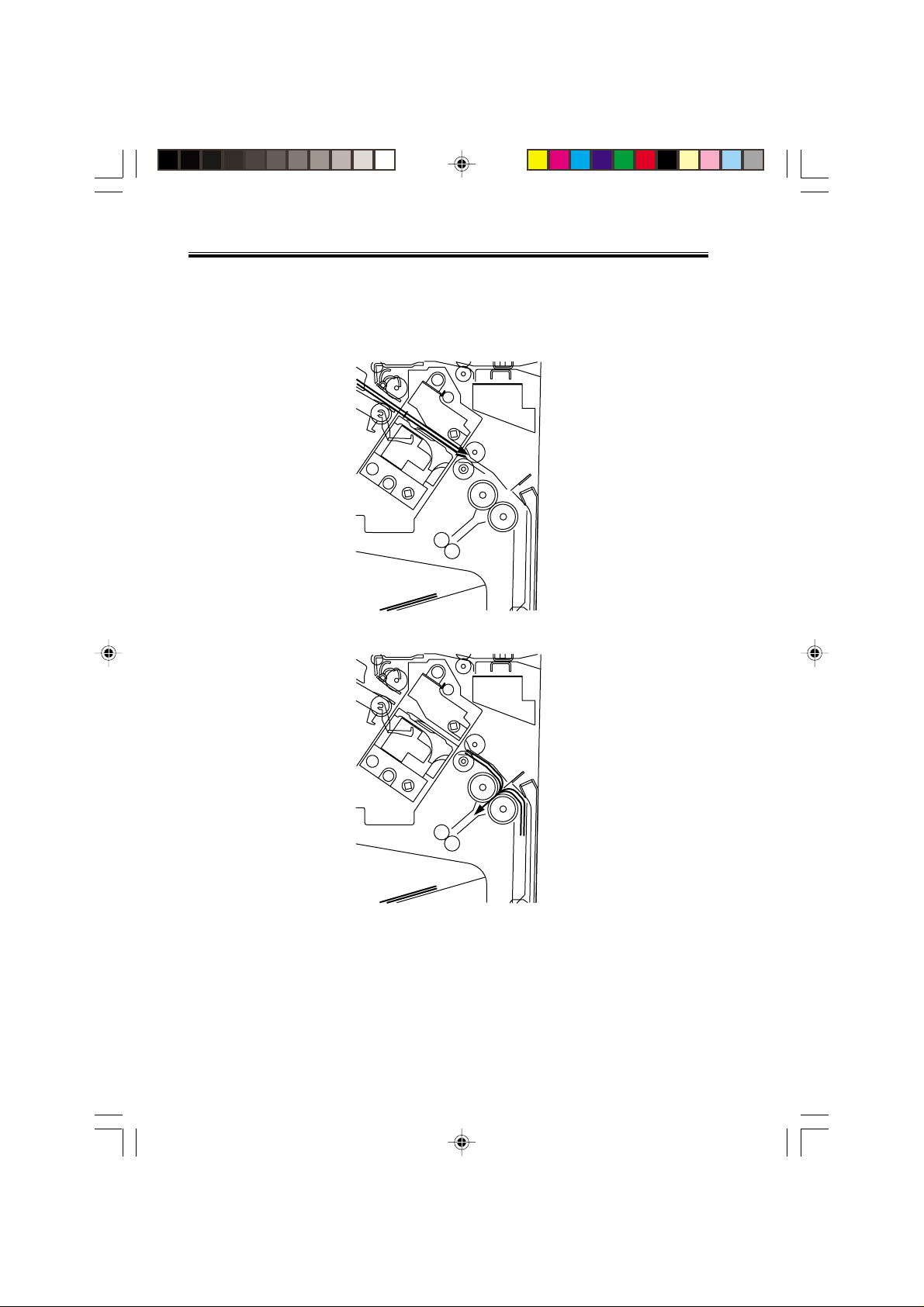
c. Stack feed
The stack feed rollers feed the paper stack to the stack folding/delivery position where the
center of the stack (stitched position) is level with the paper pushing plate and paper folding
roller's nip part.
Stack feed roller (upper)
Paper pushing plate
Stack feed roller (lower)
COPYRIGHT
Chap02.p65 3/28/01, 12:07 PM41
©
2001 CANON INC. 2000 2000 2000 2000 CANON SADDLE FINISHER G1 REV.0 MAR. 2001
Paper fold roller
F02-502-04
2-41
Page 53

CHAPTER 2 OUTLINE OF OPERATION
d. Folding/deliver y
The paper pushing plate pushes in the center of the paper stack to feed it toward the paper
fold rollers. Then, the paper fold rollers and bind delivery rollers deliver the paper stack to
the bind tray.
2-42
Chap02.p65 3/28/01, 12:07 PM42
COPYRIGHT
©
2001 CANON INC. 2000 2000 2000 2000 CANON SADDLE FINISHER G1 REV.0 MAR. 2001
Bind delivery rollers
Paper fold rollers
F02-502-05
Page 54

CHAPTER 2 OUTLINE OF OPERATION
5.3 Paper Feed System
5.3.1 Outline
The paper feed system feeds a stack of sheets (coming from the finisher) to the position
where the center of the paper stack (stitching position) is aligned to the stapler's staple, allowing the next step (stitching and folding) to be performed.
When sheets of paper have been stacked and aligned on the processing tray, the paddle
motor (M2) rotates in the reverse direction, causing the swing guide to descend. As the
swing guide descends, the paper stack is sandwiched between the upper and lower stack delivery rollers. The delivery motor (M3) rotates in the reverse direction, feeding the paper
stack toward the saddle unit. When the leading edge of the paper stack reaches the folding
position sensor (PI10), the finisher controller PCB drives the delivery motor a specified
number of motor pulses to stop the center of the paper stack (stitching position) at the
stapler's staple position. Before the paper stack passes through the stack feed rollers, the
feed motor (M1) is driven to rotate the stack feed roller (lower) so that the leading edge of
the paper stack is not bent.
Stack delivery roller (upper)
Paper stack
Fold position sensor
Stack delivery roller
COPYRIGHT
Chap02.p65 3/28/01, 12:07 PM43
(lower)
©
2001 CANON INC. 2000 2000 2000 2000 CANON SADDLE FINISHER G1 REV.0 MAR. 2001
Stack feed roller (lower)
F02-503-01
2-43
Page 55

CHAPTER 2 OUTLINE OF OPERATION
5.4 Stack Feed System
5.4.1 Outline
The stack feed system feeds the stitched paper stack to the folding position.
When stitching is complete, the feed motor (M1) rotates, causing the stack feed roller (upper) to descend. The paper stack is sandwiched between the stack feed rollers. Then, the
bind clutch (CL1) is turned ON to rotate the feed motor (M1) in the forward direction, thus
feeding the paper stack to the folding position. The feed amount is equivalent to the number
of pulses used to drive the feed motor (M1) until the paper stack reaches the folding position.
Stack feed roller (upper)
Feed amount
Stack feed roller (lower)
2-44
Chap02.p65 3/28/01, 12:07 PM44
COPYRIGHT
©
2001 CANON INC. 2000 2000 2000 2000 CANON SADDLE FINISHER G1 REV.0 MAR. 2001
F02-504-01
Page 56

CHAPTER 2 OUTLINE OF OPERATION
5.5 Fold/Delivery System
5.5.1 Outline
The paper fold mechanism consists of a guide plate, paper fold rollers, and a paper push-
ing plate.
The guide plate, paper fold rollers, and paper pushing plate are driven by the staple/fold
motor (M7). The drive force is transferred with a combination of gears and cams. Motor
operation is monitored by the staple/fold motor lock sensor (PI14).
Until the paper stack reaches the folding position, the guide plate covers the paper fold
rollers to act as a paper path through which a paper stack is fed to the saddle unit and to prevent a paper stack from touching the rollers.
A folding home position sensor (PI11) is provided to detect the positions of the paper fold
rollers and paper pushing plate.
The paper stack folded in two by the paper fold rollers is delivered by bind delivery rollers.
The bind delivery rollers are also driven by the staple/fold motor (M7).
A bind tray sensor (PI13) is provided on the bind tray to detect presence/absence of a paper stack; however, it is not used to detect a jam.
COPYRIGHT
Chap02.p65 3/28/01, 12:07 PM45
©
2001 CANON INC. 2000 2000 2000 2000 CANON SADDLE FINISHER G1 REV.0 MAR. 2001
2-45
Page 57

CHAPTER 2 OUTLINE OF OPERATION
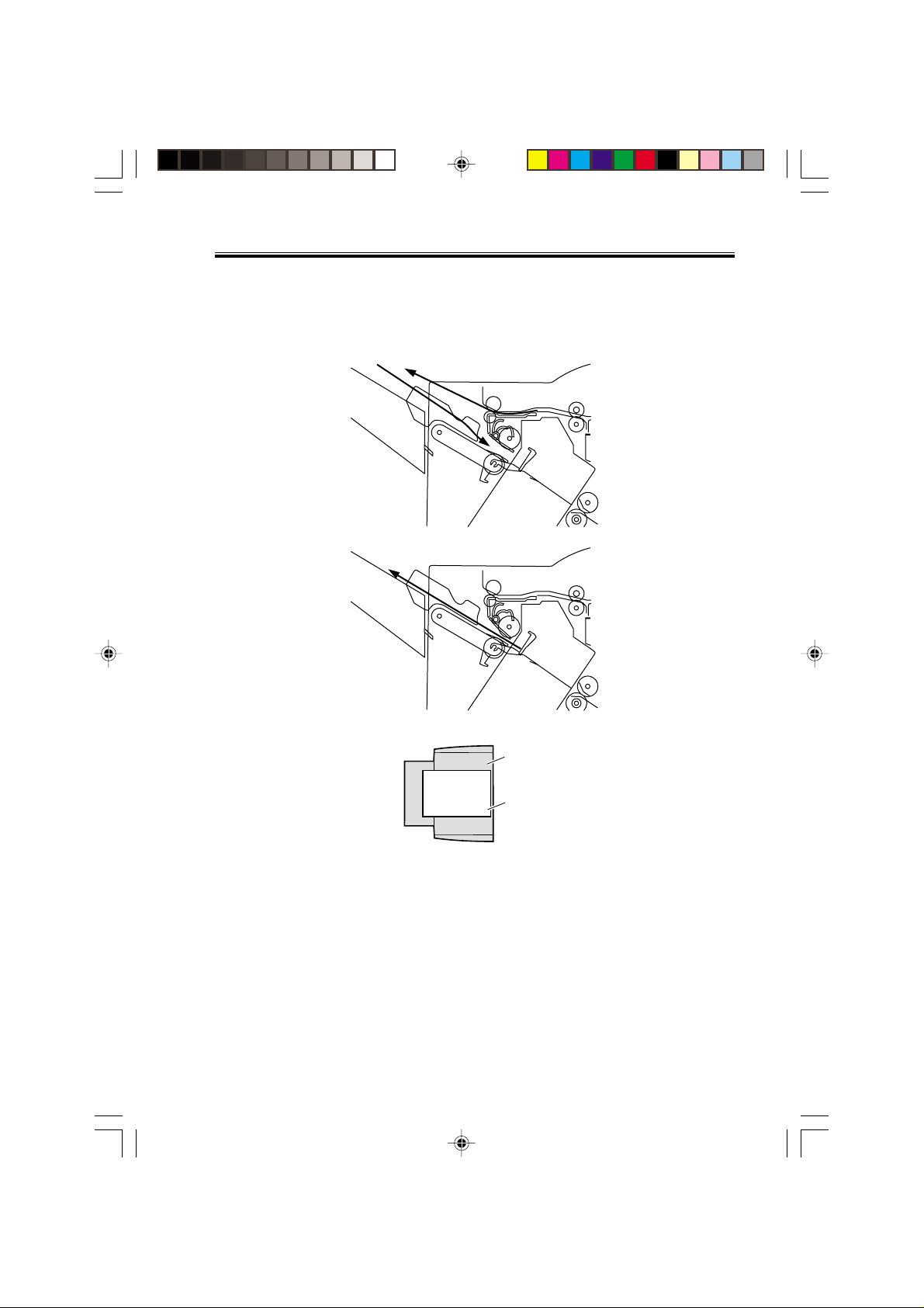
5.5.2 Paper F olding
Paper is folded using paper fold rollers and a paper pushing plate.
Almost concurrently with the start of roller rotation, the paper pushing plate starts operating to push the paper stack into the gap between the paper fold rollers. When the paper
stack is fed about 10 mm with the rotation of the paper fold rollers, the paper pushing plate
returns to the home position. Then, the paper stack is delivered to the bind tray using the
paper fold rollers and bind delivery rollers.
Half the entire surface of each paper fold roller is uncovered excluding the central area
and the area at the left and right ends. The uncovered surface of the upper paper fold roller
comes in touch with the uncovered surface of the lower paper fold roller only at the center
and left and right ends, allowing a paper stack to be fed without causing creases. The other
half of the upper paper fold roller that is covered comes in touch with the other half of the
lower paper fold roller that is also covered, allowing a paper stack to be folded while being
fed.
Sensor flag
Folding home position sensor (PI11)
Came
Paper stack
Paper fold roller (upper)
Staple/fold
motor
2-46
M7
Paper fold roller (lower)
COPYRIGHT
Paper pushing plate
F02-505-01
©
2001 CANON INC. 2000 2000 2000 2000 CANON SADDLE FINISHER G1 REV.0 MAR. 2001
Chap02.p65 3/28/01, 12:07 PM46
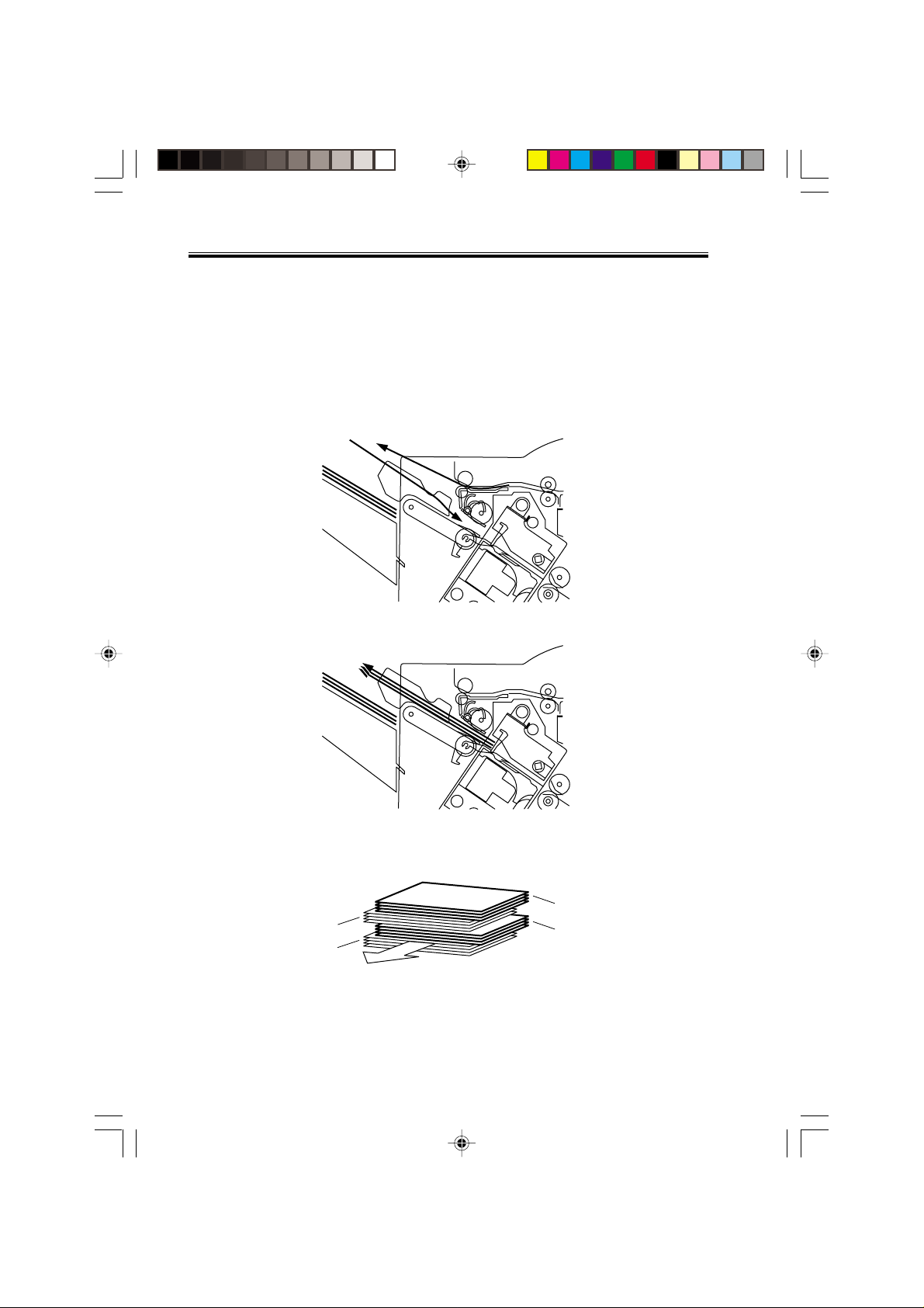
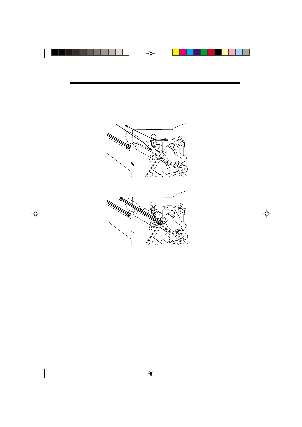
Page 58

Paper fold roller (upper)
CHAPTER 2 OUTLINE OF OPERATION
Folding
home position sensor (PI11)
Paper pushing plate
Staple/fold
motor
Paper fold roller (lower)
M7
Paper stack
[Paper folding start position]
Outlet
F02-505-02
Paper stack
Inlet
Paper push plate
COPYRIGHT
Chap02.p65 3/28/01, 12:07 PM47
©
2001 CANON INC. 2000 2000 2000 2000 CANON SADDLE FINISHER G1 REV.0 MAR. 2001
Folds/feeds a paper stack.
Feeds a paper stack.
F02-505-03
2-47
Page 59

CHAPTER 2 OUTLINE OF OPERATION
Feed motor (M1)
Delivery motor (M3)
Paddle motor (M2)
Paddle home position
sensor (PI2)
Swing guide home
position sensor (PI3)
Stapler safety switch
(MS3)
Slide motor (M8)
Staple/fold motor (M7)
Staple home position
sensor (PI19)
Folding position sensor
(PI10)
Stack feed roller (upper)
home position sensor (PI12)
Binding cluch (CL1)
Folding home position
sensor (PI11)
Bind tray sensor (PI13)
Staply
?????
13571msec
50msec
2-48
Chap02.p65 3/28/01, 12:18 PM48
COPYRIGHT
©
2001 CANON INC. 2000 2000 2000 2000 CANON SADDLE FINISHER G1 REV.0 MAR. 2001
CW rotation CCW rotation
F02-505-04
Page 60

CHAPTER 2 OUTLINE OF OPERATION
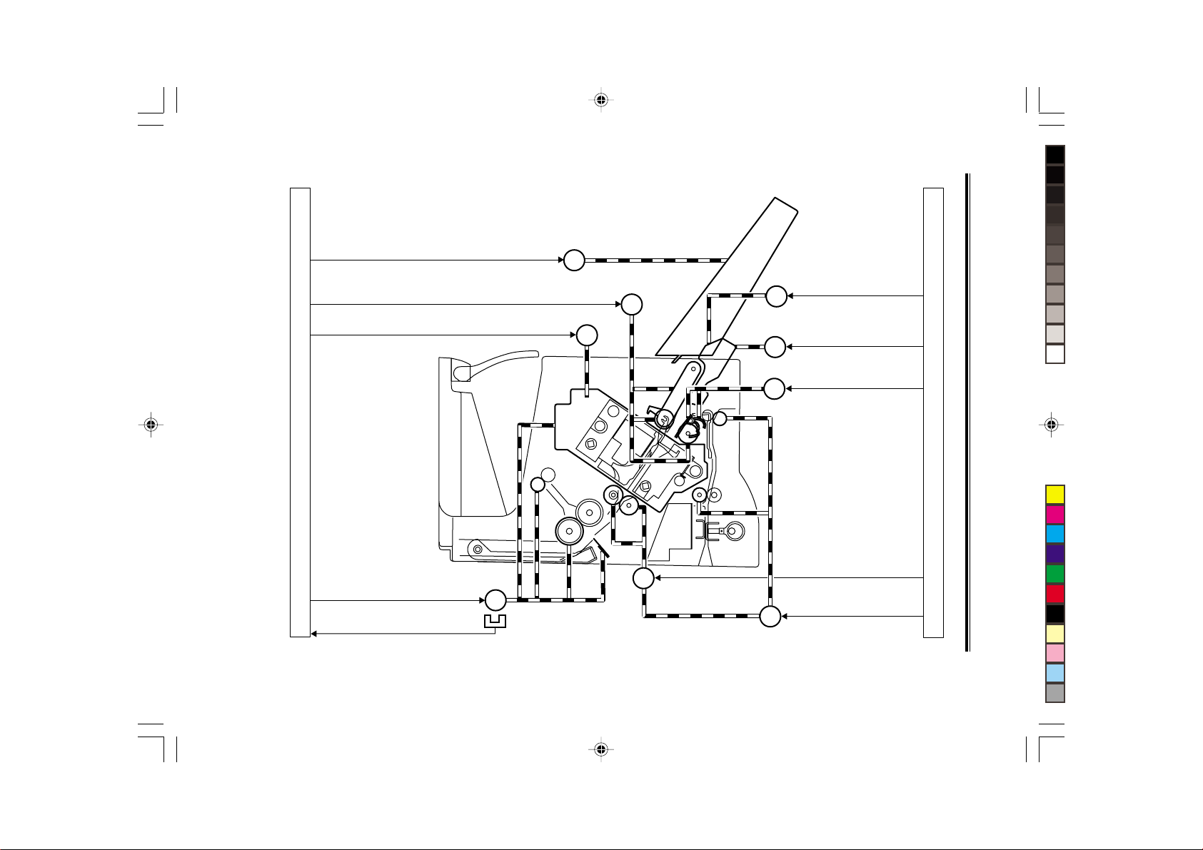
6 Puncher Unit (option)
6.1 Basic Operations
6.1.1 Outline
The puncher unit is an option, and is designed for installation to the pickup assembly of
the finisher. The puncher unit is not equipped with a paper feeding mechanism, and the
sheets from the host machine move through the puncher unit and then the feed system of the
finisher.
When the trailing edge of a sheet from the host machine reaches the puncher unit, the
sheet is stopped once, and the punch shaft is rotated to punch a hole along the trailing edge.
These operations are controlled with various commands from the finisher controller PCB as
well as the commands from the punch controller PCB.
Punch drive system
Horizontal registration
drive system
Punch controller PCB
COPYRIGHT
Chap02.p65 3/28/01, 12:07 PM49
©
2001 CANON INC. 2000 2000 2000 2000 CANON SADDLE FINISHER G1 REV.0 MAR. 2001
Finisher unit control system
F02-601-01
2-49
Page 61

CHAPTER 2 OUTLINE OF OPERATION
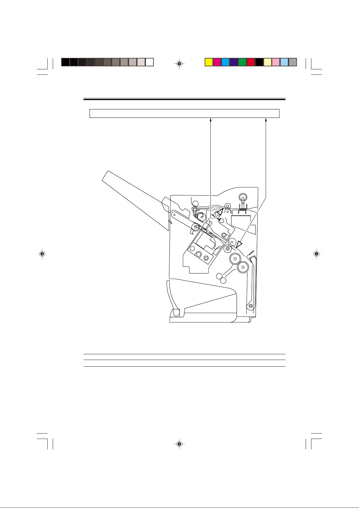
6.2 Punching Operation
6.2.1 Outline
The puncher unit is located in the pickup assembly of the finisher, and is used to punch
holes in sheets that have been sent from the host machine and stopped inside it. When the
trailing edge of a sheet reaches the puncher unit, the inlet roller of the finisher assembly
stops the sheet to punch a hole along the trailing edge of the sheet.
The punch unit consists of a die and hole puncher (punch blade).
The hole puncher is driven by the punch motor (M1P). It is attached to the eccentric cam
of the punch shaft, and the rotation of the punch shaft is converted into reciprocating motion
for punching operation.
The punch motor (M1P) is a DC motor. The home position of the punch shaft is detected
by the punch home position sensor (PI1P). To make sure that the punch motor, which is a
DC motor, stops exactly at its home position, the punch motor is stopped in relation to the
count of the clock pulses kept by the punch motor clock sensor (PI3P).
A single punching operation is executed by rotating the punch shaft 180° from its home
position.
As many as five light-receiving transistors (photosensor PCB) are mounted over the inlet
paper path of the puncher unit; on the other hand, as many as five LEDs (LED PCB) are
mounted under the path, together serving as five sensors. The frontmost sensor (LED5, PT5)
is used to detect the training edge of sheets, and the remaining four (LED1 through LED4,
PT1 through PTR4) are used as horizontal registration sensors to detect the rear position of
sheets when punching holes.
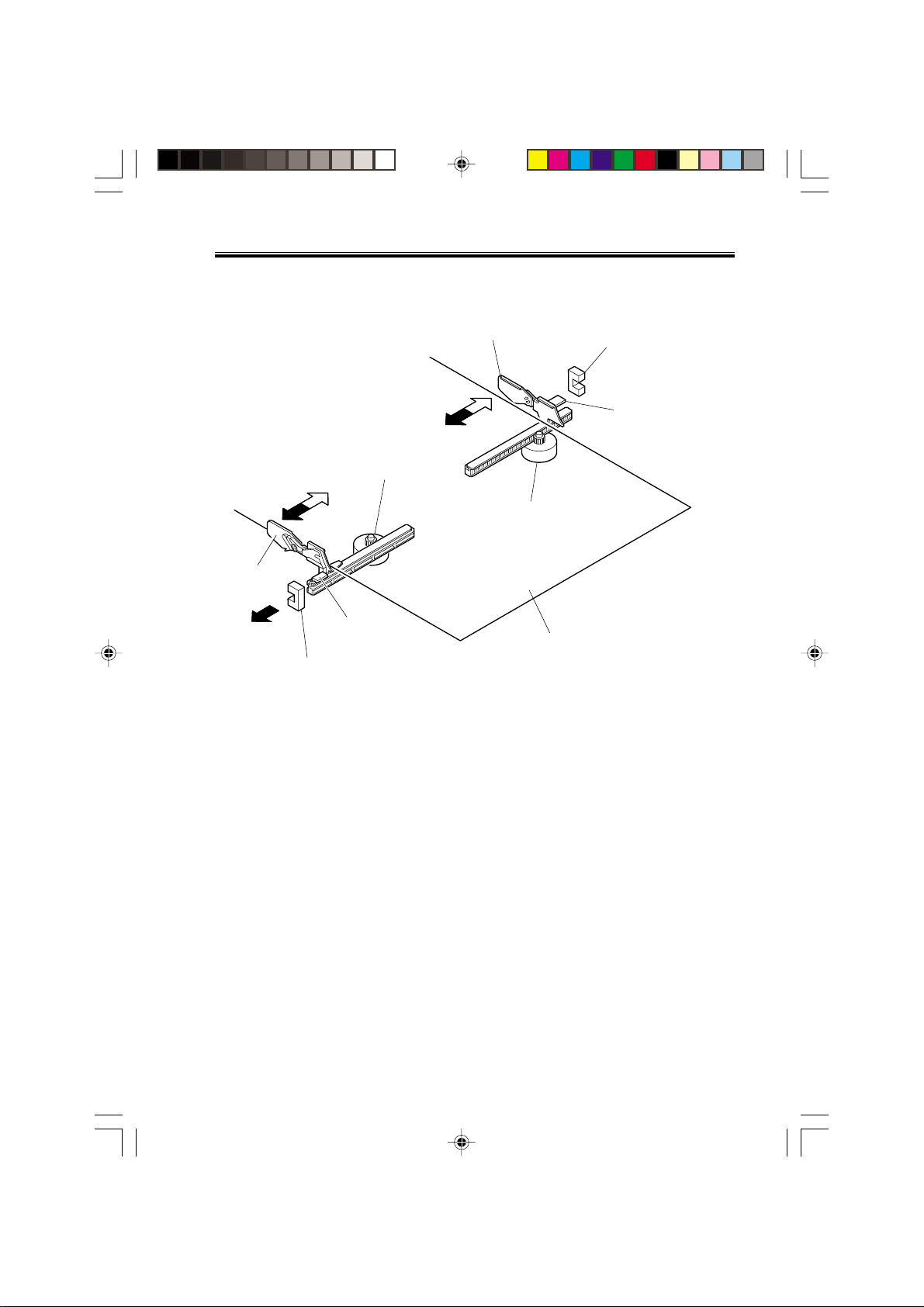
The punch motor, punch unit, and sensors make up the punch slide unit, which moves to
the front/rear to suit the selected paper size. The movement to the front/rear is driven by the
horizontal registration motor (M2P). The home position of the punch slide unit is detected
by the horizontal registration home position sensor (PI2P), and the horizontal registration
motor (M2P) is a stepping motor.
The punch motor and horizontal registration motor are controlled with various commands
from the finisher controller PCB as well as the commands from the punch controller PCB.
The waste paper occurring as the result of punching is collected in the waste paper case.
The case is monitored by the LED121 on the waste full LED PCB and PT131 on the waste
full photosensor PCB.
2-50
Chap02.p65 3/28/01, 12:07 PM50
COPYRIGHT
©
2001 CANON INC. 2000 2000 2000 2000 CANON SADDLE FINISHER G1 REV.0 MAR. 2001
Page 62

Chap02.p65 3/28/01, 12:07 PM51
COPYRIGHT
©
2001 CANON INC. 2000 2000 2000 2000 CANON SADDLE FINISHER G1 REV.0 MAR. 2001
LED121
2-51
Punch controller PCB (2/2)
F02-602-01
Punch motor clock (PI3P)
detection signal PUNCHCLK
Waste full detection signal
(LED121, PT131) DFULL
Horizontal registration home position
(PI2P) detection signal SREGHP
Punch home position (PI1P)
detection signal PUNCHHP
PT131
Trailing edge detection signal
(LED5, PT5) PAEND
Horizonal registration detection
signal (LED1~4, PT1~4) SREG1~4
5
5
4
4
3
3
2
2
PT1
LED1
Punch motor (M1P) drive signal
Punch controller PCB (1/2)
CHAPTER 2 OUTLINE OF OPERATION
Horizontal registration motor
(M2P) drive signal
Page 63

CHAPTER 2 OUTLINE OF OPERATION
6.2.2 Punching Operation
The hole puncher is driven by the punch motor (M1P). The home position for the hole
puncher is detected by the punch home position sensor (PI1P).
The punch unit comes in four types, selected to suit the country of installation: 2-hole
(Puncher Unit-J1), 2- and 3-hole (Puncher Unit-K1), or two types of 4-hole (Puncher UnitG1, Puncher Unit-H1).
The 2-hole and 4-hole types punch a hole when the punch shaft is rotated 180° from the
home position, causing the punch to make a single round trip. The 2-/3-hole type punches a
hole, but the circumference of the punch shaft is divided into two (half for 2-hole and the
other half for 3-hole).
2-52
Chap02.p65 3/28/01, 12:07 PM52
COPYRIGHT
©
2001 CANON INC. 2000 2000 2000 2000 CANON SADDLE FINISHER G1 REV.0 MAR. 2001
Page 64

CHAPTER 2 OUTLINE OF OPERATION
a. 2-Hole, 4-Hole Type
The home position is identified when the punch home position is ON. The punching operation for the first sheet ends when the punch shaft has rotated 180° and the punch home
position sensor goes ON; the punching operation for the second sheet ends when the punch
shaft has rotated 180° in reverse and the punch home position sensor goes ON.
The punching operation takes place as follows when making a hole in two sheets of paper.
1) A hole is punched along the trailing edge of the 1st sheet.
Sensor flag
Punch home position
sensor (PI1P)
Punch shaft
Eccentric cam
Die
Die
(punch shaft at
rest/home position)
Hole
puncher
Paper
Waste paper
(punch shaft CW rotation
by 90˚/hole made)
F02-602-02
2) A hole is made along the trailing edge of the 2nd sheet.
(punch shaft at rest/
home position)
(punch shaft CCW rotation
by 90˚/hole made)
(punch shaft CCW rotation by 180˚/
F02-602-03
(punch shaft CW rotation by 180˚/
punching operation ends)
end of punching operation)
COPYRIGHT
Chap02.p65 3/28/01, 12:07 PM53
©
2001 CANON INC. 2000 2000 2000 2000 CANON SADDLE FINISHER G1 REV.0 MAR. 2001
2-53
Page 65

CHAPTER 2 OUTLINE OF OPERATION
b. 2- /3-Hole Type
The home position is identified when the punch home position sensor is ON. To make
two holes, the punching operation for the first sheet ends when the punch shaft rotates 180°
(half circumference) and the punch home position sensor goes ON. At this time, the 3-hole
puncher makes a single round trip in escape direction (moving up the hole puncher) on a
half circumference of the punch shaft.
The punching operation for the second sheet ends when the Punch shaft has rotated 180°
counterclockwise and the punch home position sensor goes ON (half circumference). At this
time, the 3-hole puncher makes a single round trip in escape direction (moving up the hole
puncher) on the other half circumference of the punch shaft.
The punching operation takes place as follows when making two holes in two sheets of
paper:
1) A hole is made along the trailing edge of the 1st sheet.
Sensor flag
Punch home position
sensor (PI1P)
Punch shaft
2-54
Eccentric cam
Die
Die
(punch shaft at rest/
home position)
COPYRIGHT
Hole
puncher
Paper
Waste paper
(punch shaft CW rotation
by 90˚/hole made)
(punch shaft CW rotation by 180˚/
end of punching operation)
F02-602-04
©
2001 CANON INC. 2000 2000 2000 2000 CANON SADDLE FINISHER G1 REV.0 MAR. 2001
Chap02.p65 3/28/01, 12:07 PM54
Page 66

CHAPTER 2 OUTLINE OF OPERATION
/
While two holes are being made, the 3-hole puncher makes a single round trip in escape
direction.
(punch shaft at rest/
home position)
(punch shaft CW rotation by 90˚/
punch at upper limit)
F02-602-05
2) Holes are made along the trailing edge of the 2nd sheet.
(punch shaft at rest/
home position)
(punch shaft CCW rotation
by 90˚/hole made)
(punch shaft CCW rotation by 180˚
F02-602-06
(punch shaft CW rotation by 180˚/
punch back to initial position)
end of punching operation)
COPYRIGHT
Chap02.p65 3/28/01, 12:07 PM55
©
2001 CANON INC. 2000 2000 2000 2000 CANON SADDLE FINISHER G1 REV.0 MAR. 2001
2-55
Page 67

CHAPTER 2 OUTLINE OF OPERATION
While two hole are being made, the 3-hole puncher makes a single round trip in escape
direction (moving up the hole puncher).
(punch shaft at rest/
home position)
(punch shaft CCW rotation by
90˚/punch at upper limit)
F02-602-07
(punch CCW rotation by 180˚/
punch back at initial position)
2-56
Chap02.p65 3/28/01, 12:07 PM56
COPYRIGHT
©
2001 CANON INC. 2000 2000 2000 2000 CANON SADDLE FINISHER G1 REV.0 MAR. 2001
Page 68

CHAPTER 2 OUTLINE OF OPERATION
6.2.3 Horizontal Registration Operation
The horizontal registration drive for the punch slide unit is provided by the horizontal registration motor (M2P). The home position of the punch slide unit is detected by the horizontal registration home position sensor (PI2P). The punch slide unit detects the trailing edge of
sheets using the trailing edge sensor (LED5, PT5) and the horizontal registration sensors
(LED1 through 4, SREG1 through 4), and causes a move to a specific position matching the
trailing edge of each sheet (in relation to the size of the sheet).
The horizontal registration operation takes place as follows:
1) When the leading edge of a sheet from the host machine is detected by the trailing edge
sensor (LED5, PT5), the horizontal registration motor (M2P) starts to move the punch
slide unit toward the front.
Punch slide unit
Horizontal registration
motor (M2P)
Trailing edge sensor
(LED5, PT5)
(direction of
paper delivery)
COPYRIGHT
Chap02.p65 3/28/01, 12:07 PM57
©
2001 CANON INC. 2000 2000 2000 2000 CANON SADDLE FINISHER G1 REV.0 MAR. 2001
Paper
F02-602-08
2-57
Page 69

CHAPTER 2 OUTLINE OF OPERATION
2) When the horizontal registration sensor (LED1 through 4, PT1 through) suited to the
paper size signal from the host machine detects the rear edge of the sheet, the horizontal registration motor (M2P) causes a farther move to a specific position, and stops the
punch slide unit.
Horizontal registration sensor (LED1, PT1);
used to detect the edge of sheets of A3, A4,
LTR, 279×432 (11"×17").
Horizontal registration sensor 2 (LED2, PT2);
used to detect the edge of sheets of B4, B5,
LTRR, LGL.
Horizontal registration sensor 3 (LED3, PT3);
used to detect the edge of sheets of A4R.
Horizontal registration sensor 4 (LED4, PT4);
used to detect the edge of sheets of B5R.
F02-602-09
3) When the trailing edge sensor (LED5, PT5) detects the trailing edge of the sheet, the
drive of the feed motor (M1) is stopped, thereby stopping the sheet. Then, the punch
motor (M1P) is driven to punch holes in the sheet.
2-58
Chap02.p65 3/28/01, 12:07 PM58
COPYRIGHT
©
2001 CANON INC. 2000 2000 2000 2000 CANON SADDLE FINISHER G1 REV.0 MAR. 2001
Punch
F02-602-10
Page 70

CHAPTER 2 OUTLINE OF OPERATION
4) When the punching operation ends, the feed motor (M1) of the fisher unit is driven and,
at the same time, the horizontal registration motor (M2P) is rotated in reverse to return
the punch slide unit to its home position.
5) For each sheet that arrives in succession, the punch slide unit is returned to its home position, and is caused to repeat steps 1 through 4 .
Trailing edge sensor
(LED5, PT5)
Horizontal registration
sensor (LED1~4, PT1~4)
Punch home position
sensor (PI1P)
Horizontal registration home
position sensor (PI2P)
Horizontal registration
motor (M2P)
Punch motor (M1P)
Feed motor (M1)
: CW rotation : CCW rotation
F02-602-11
COPYRIGHT
Chap02.p65 3/28/01, 12:07 PM59
©
2001 CANON INC. 2000 2000 2000 2000 CANON SADDLE FINISHER G1 REV.0 MAR. 2001
2-59
Page 71

CHAPTER 2 OUTLINE OF OPERATION
7 Detecting Jams
7.1 Outline
The microprocessor (CPU) on the finisher controller PCB is programmed to check for
jams in the finisher/saddle/puncher (option) at such times as set in advance. It identifies a
jam in reference to the presence/absence of paper at a specific sensor. If a jam is found, the
finisher controller PCB communicates the nature of the jam to the host machine in the form
of a code (which may be checked in service mode of the host machine).
PI1
PI10
PI1: inlet sensor.
PI10 Folding position sensor
2-60
Chap02.p65 3/28/01, 12:07 PM60
COPYRIGHT
©
2001 CANON INC. 2000 2000 2000 2000 CANON SADDLE FINISHER G1 REV.0 MAR. 2001
F02-701-01
Page 72

CHAPTER 2 OUTLINE OF OPERATION
7.1.1 Inlet Sensor Delay Jam (1011)
The inlet sensor does not detect paper approximately 1.5 sec after the host machine gener-
ates the delivery signal.
Host machine delivery signal
Jam check
Inlet sensor (PI1)
Feed motor (M1)
approx. 1.5sec.
Normal
Host machine delivery signal
Jam check
Inlet sensor (PI1)
Feed motor (M1)
approx. 1.5sec.
Jam
F02-701-02
7.1.2 Inlet Sensor Stationary Jam (1021)
The paper does not leave the inlet sensor approximately 2 sec after the inlet sensor has de-
tected its leading edge.
Jam check
Inlet sensor (PI1)
Feed motor (M1)
approx. 2sec.
Normal
Jam check
Inlet sensor (PI1)
Feed motor (M1)
approx. 2sec.
Jam
F02-701-03
7.1.3 Folding Position Sensor Delay Jam (1012)
In bind mode, the folding position sensor does not detect paper 1200 msec after the inter-
mediate processing tray starts to send paper to the stapling position.
Jam check
Folding position
sensor (PI10)
Delivery motor (M3)
COPYRIGHT
Chap02.p65 3/28/01, 12:07 PM61
©
2001 CANON INC. 2000 2000 2000 2000 CANON SADDLE FINISHER G1 REV.0 MAR. 2001
1200 ms
Normal
Jam check
Folding position
sensor (PI10)
Delivery motor (M3)
F02-701-04
1200 ms
Jam
2-61
Page 73

CHAPTER 2 OUTLINE OF OPERATION
7.1.4 Folding Position Sensor Stationary Jam (1022)
In bind mode, paper does not leave the holding position sensor approximately 10.5 sec
after the staple/fold motor is driven.
Jam check
Folding position
sensor (PI10)
Staple/fold
motor (M7)
approx. 10.5sec. approx. 10.5sec.
Normal
Jam check
Folding position
sensor (PI10)
Staple/fold
motor (M7)
Jam
F02-701-05
7.1.5 Po wer-On J am (1007)
Paper is detected inside the finisher at power-on or when the door is closed.
7.1.6 Door Open Jam (paper present) (1008)
The finisher is disconnected from its host machine or the front door, or the upper cover is
opened while the system is in operation (paper on the move).
7.1.7 Staple Jam (1006)
The staple home position sensor (PI19) does not go OFF 600 msec after the stapler is
driven. Or, it does not return to its home position (where the sensor goes ON).
2-62
Chap02.p65 3/28/01, 12:07 PM62
COPYRIGHT
©
2001 CANON INC. 2000 2000 2000 2000 CANON SADDLE FINISHER G1 REV.0 MAR. 2001
Page 74

CHAPTER 2 OUTLINE OF OPERATION
8 Power Supply System
8.1 Finisher/Saddle Assembly
8.1.1 Outline
When the host machine is turned on, it supplies the finisher controller PCB with two
channels of 24 VDC; one is for the motors and clutches, and the other is turned into 5 VDC
by the regulator IC (IC1) of the finisher controller PCB for use by the sensors and ICs on
PCBs.
If a punch unit (option) is installed, power is also supplied to the punch controller PCB.
Some of 24 VDC used to drive motors is cut off when the joint switch (MS2), front door
switch (MS1), or stapler safety switch (MS3) is open.
F02-801-01 is a block diagram of the power supply system:
Front door switch
Joint switch
(MS2)
(MS1)
Stapler safety switch
(MS3)
24 V
Motor
Host
machine
24VP
24VL
Circuit Breaker
(CB1)
Finisher
controler PCB
(IC1)
Regurator IC
24 V
24 V
Punch controller PCB
(puncher unit; option)
5 V
5 V
Motor
Clutch
Sensor
Logic system
F02-801-01
8.1.2 Protective Mechanisms
A circuit breaker (CB1) is monitored to protect the 24 VDC system sued to drive the motors against overcurrent. The 24-V system used to drive the feed motor (M1), paddle motor
(M2), and delivery motor (M3) is equipped with a fuse which melts in the presence of
overcurrent.
COPYRIGHT
Chap02.p65 3/28/01, 12:07 PM63
©
2001 CANON INC. 2000 2000 2000 2000 CANON SADDLE FINISHER G1 REV.0 MAR. 2001
2-63
Page 75

CHAPTER 2 OUTLINE OF OPERATION
8.2 Puncher Unit (option)
8.2.1 Outline
When the host machine is turned on, the puncher unit is supplied by the finisher control-
ler PCB with 24-V and 5-V power.
The 24-V power is used to drive the motors, while the 5-V power is used by sensors and
the ICs on the punch controller PCB.
The 24-V power to the motors will be cut off when the joint switch (MS2) or the front
door switch (MS1) of the finisher unit is open.
F02-802-01 is a block diagram for the power supply system:
Finisher
controller
PCB
24 V
Punch controller PCB
5 V
24 V
5 V
5 V
Motors
Sensors
Logic system
F02-802-01
8.2.2 Protective Mechanisms
The 24-V system used to drive the punch motor (M1P) and the horizontal registration mo-
tor (M2P) is equipped with a built-in fuse which melts in the presence of overcurrent.
2-64
Chap02.p65 3/28/01, 12:07 PM64
COPYRIGHT
©
2001 CANON INC. 2000 2000 2000 2000 CANON SADDLE FINISHER G1 REV.0 MAR. 2001
Page 76

CHAPTER 3
MECHANICAL SYSTEMS
COPYRIGHT
#ChapterCover.p65 3/28/01, 12:05 PM3
©
2001 CANON INC. 2001 2001 2001 2001 CANON SADDLE FINISHER G1 REV.0 MAR. 2001
Page 77

1 Finisher Saddle Unit
[2]
[1]
1.1 Externals and Controls
[1] Tray (2)
[2] Rear cover (3)
[3] Front cover (5)
[4] Front door
[5] Upper door
[6] Upper right cover assembly (4)
[7] Jam removal cover
The number in parentheses indicates the
number of mounting screws used.
1.1.1 Removing the Delivery Tra y
1) Remove the four screw [1], and detach
the delivery tray [2].
CHAPTER 3 MECHANICAL SYSTEMS
[1] [2]
[4]
[5] [6]
[7]
[3]
F03-101-01
COPYRIGHT
Chap03.p65 3/28/01, 12:09 PM1
©
2001 CANON INC. 2000 2000 2000 2000 CANON SADDLE FINISHER G1 REV.0 MAR. 2001
F03-101-02
3-1
Page 78

CHAPTER 3 MECHANICAL SYSTEMS
1.1.2 Removing the Front Co v er
1) Open the front door [1].
2) While picking the claw [2], detach the
fold jam releasing dial [3].
3) Remove the two screws [4].
[1] [4]
[3]
[2]
[4]
F03-101-03
4) Remove the three screws [5], and detach
the front cover [6].
[6]
[5]
[5]
F03-101-04
3-2
Chap03.p65 3/28/01, 12:09 PM2
COPYRIGHT
©
2001 CANON INC. 2000 2000 2000 2000 CANON SADDLE FINISHER G1 REV.0 MAR. 2001
Page 79

1.1.3 Removing the Rear Cov er
[3]
[1]
1) Remove the two screws [1] on the
pickup side, and remove the screw [2]
on the delivery side; then, detach the
rear cover [3].
CHAPTER 3 MECHANICAL SYSTEMS
F03-101-05
[3]
1.1.4 Removing the Upper Cov er
1) Open the upper cover [1], and turn the
cover band retainer [2] to the left to remove it.
2) Remove the cover band [3].
COPYRIGHT
Chap03.p65 3/28/01, 12:09 PM3
©
2001 CANON INC. 2000 2000 2000 2000 CANON SADDLE FINISHER G1 REV.0 MAR. 2001
F03-101-06
[1]
[3]
F03-101-07
[2]
[2]
3-3
Page 80

CHAPTER 3 MECHANICAL SYSTEMS
3) Remove the screw [4], and detach the
processing tray rear cover [5]; then, detach the upper cover [6].
[5]
1.1.5 Removing the Processing Tra y Upper Co v er
1) Remove the front cover. (See 1.1.2.)
2) Remove the rear cover. (See 1.1.3.)
3) Remove the upper cover. (See 1.1.4.)
4) Disconnect the connector [1], and remove the screw [2].
[6]
[4]
F03-101-08
3-4
Chap03.p65 3/28/01, 12:09 PM4
COPYRIGHT
©
[2]
[1]
F03-101-09
2001 CANON INC. 2000 2000 2000 2000 CANON SADDLE FINISHER G1 REV.0 MAR. 2001
Page 81

CHAPTER 3 MECHANICAL SYSTEMS
5) While lifting the processing tray upper
cover [3], disconnect the connector [4];
then, detach the processing tray upper
cover [3].
1.1.6 Removing the Upper Right Cov er Assemb ly
1) Remove the front cover. (See 1.1.2.)
2) Remove the rear cover. (See 1.1.3.)
3) Remove the two screws [1] at the front
and the two screws [2] at the rear; then,
detach the upper right cover assembly
[3].
[1]
[3]
[4]
F03-101-10
[3]
COPYRIGHT
Chap03.p65 3/28/01, 12:09 PM5
©
2001 CANON INC. 2000 2000 2000 2000 CANON SADDLE FINISHER G1 REV.0 MAR. 2001
F03-101-11
[3]
[2]
F03-101-12
3-5
Page 82

CHAPTER 3 MECHANICAL SYSTEMS
1.1.7 Removing the Saddle Guide
1) Remove the delivery tray. (See 1.1.1.)
2) Remove the front cover. (See 1.1.2.)
3) Remove the rear cover. (See 1.1.3.)
4) Free the delivery tray support plate
(front) [1] and the delivery tray support
plate (rear) [2] to the outside from the
rail grooves.
5) Remove the four screws [3].
[3]
[2]
[3]
[3]
[1]
[3]
F03-101-13
6) Shift the side guide [4] lightly to the
front, and free the engagement of the
paper surface detecting lever (rear) [5];
then, detach the side guide [4].
Be sure to mount the side guide
after securely fitting the paper
surface detecting lever (rear) [5]
in the groove of the paper surface detecting lever (middle)
[6].
After completion of mounting,
push the paper surface detecting
lever several times to make sure
that side guide is mounted securely.
[5]
F03-101-14
[5]
[5]
[4]
[6]
[6]
3-6
Chap03.p65 3/28/01, 12:09 PM6
COPYRIGHT
©
F03-101-15
2001 CANON INC. 2000 2000 2000 2000 CANON SADDLE FINISHER G1 REV.0 MAR. 2001
Page 83

1.2 Feeding System
1.2.1 Removing the Stapler Unit
1) Open the front door [1].
2) Slide out the stapler unit [3] while pressing the stopper lever [2].
CHAPTER 3 MECHANICAL SYSTEMS
[1]
[3]
[2]
F03-102-01
COPYRIGHT
©
Do not remove the stapler from
the stapler frame shaft. If re-
[5]
moved, the position where the
staple driver (lower unit of the
stapler) [4] shoots stables will
[4]
shift from the position where
the staple clincher (upper unit of
the stapler) [5] receives staples.
F03-102-02
2001 CANON INC. 2000 2000 2000 2000 CANON SADDLE FINISHER G1 REV.0 MAR. 2001
3-7
Chap03.p65 3/28/01, 12:09 PM7
Page 84

CHAPTER 3 MECHANICAL SYSTEMS
1.2.2 Adjusting the Stapler Phase
When the gears or timing belt at the front of
the stapler is replaced or removed for some
reason, the staple shooting timing of the
staple driver (lower unit of the stapler) does
not match the staple bending timing of the
staple clincher (upper unit of the stapler).
Adjust the stapler phase following the procedure described below.
Gear
Timing belt
Gear
F03-102-03
1) Detach the gear cover [2] from the staple
driver [1].
2) Remove the E-ring [3] to detach the side
cover [5] of the staple clincher [4].
[4]
[3]
[5]
[2]
[1]
F03-102-04
3-8
Chap03.p65 3/28/01, 12:09 PM8
COPYRIGHT
©
2001 CANON INC. 2000 2000 2000 2000 CANON SADDLE FINISHER G1 REV.0 MAR. 2001
Page 85

3) Remove the two E-rings [6] to remove
the staple jam releasing gear [7], timing
belt [8], and relay gear 1 [9]. Remove
the spacer and spring at the back of the
staple jam relasing gear.
4) Remove the screw [10] and spring [11]
to remove the belt tentioner [12].
CHAPTER 3 MECHANICAL SYSTEMS
[7]
[8]
[6]
[9]
5) Remove the timing belt [13].
6) Remove the E-ring [14] to remove the
staple position check gear [15].
[11]
[10]
[12]
F03-102-05
[15]
[14]
[13]
F03-102-06
COPYRIGHT
Chap03.p65 3/28/01, 12:09 PM9
©
2001 CANON INC. 2000 2000 2000 2000 CANON SADDLE FINISHER G1 REV.0 MAR. 2001
3-9
Page 86

CHAPTER 3 MECHANICAL SYSTEMS
7) Turn the gear [16] to align the round
hole in the staple driver gear with the
round hole [17] at the back.
8) Insert a pin [18] with a diameter of approximately 2 mm (use of a 2 mm Allen
wrench is recommended) in the round
hole to secure the gear.
[16]
[17]
F03-102-07
3-10
Chap03.p65 3/28/01, 12:09 PM10
COPYRIGHT
©
2001 CANON INC. 2000 2000 2000 2000 CANON SADDLE FINISHER G1 REV.0 MAR. 2001
[18]
F03-102-08
Page 87

9) Turn the gear [19] to align the round
hole in the staple clincher cam with the
round hole [20] at the back.
10) Insert a pin [21] with a diameter of approximately 2 mm (use of a 2 mm Allen
wrench is recommended) in the round
hole to secure the gear.
CHAPTER 3 MECHANICAL SYSTEMS
[19]
[20]
F03-102-09
COPYRIGHT
Chap03.p65 3/28/01, 12:09 PM11
©
2001 CANON INC. 2000 2000 2000 2000 CANON SADDLE FINISHER G1 REV.0 MAR. 2001
[21]
F03-102-10
3-11
Page 88

CHAPTER 3 MECHANICAL SYSTEMS
11) With the gears and cam fixed, install
the timing belt [22] on gears [23] and
[24].
[23]
[22]
[24]
F03-102-11
12) Mount the staple position check gear
[27] so that the blue mark [25] on the
staple position check gear is aligned
with the round hole [26] in the frame.
The position where the blue
mark is aligned with the round
hole is the home position for
stapling. If the staple jam cancel dial is turned for some reason, the home position deviates,
making it impossible to remove
the stapler cartridge. If such a
case, the gear can be returned to
the home position by checking
blue mark position. Therefore,
it is necessary to mount the gear
at the correct position.
[26]
[25]
[27]
F03-102-12
3-12
Chap03.p65 3/28/01, 12:09 PM12
COPYRIGHT
©
2001 CANON INC. 2000 2000 2000 2000 CANON SADDLE FINISHER G1 REV.0 MAR. 2001
Page 89

CHAPTER 3 MECHANICAL SYSTEMS
13) Remove the pin securing the gear to the
[28]
cam.
14) Assemble the spring [28], spacer [29],
staple jam releasing gear [30], timing
belt [31], and relay gear [32] and secure
them with the E-ring [33].
[29]
[30]
F03-102-13
1.2.3 Adjusting the Phase of the Gear in the Saddle Unit
If the gears at the front of the saddle unit or
the paper fold rollers in the sale unit are replaced or removed for some reason, adjust
the gear phase following the procedure described below.
1) The paper fold rollers [1] and saddle
cam [2] must be positioned as shown
below.
[31]
[32]
[33]
[2]
[1]
COPYRIGHT
Chap03.p65 3/28/01, 12:09 PM13
©
2001 CANON INC. 2000 2000 2000 2000 CANON SADDLE FINISHER G1 REV.0 MAR. 2001
F03-102-14
3-13
Page 90

CHAPTER 3 MECHANICAL SYSTEMS
2) With the paper fold rollers and saddle
cam positioned as shown in Figure F03102-14, mount gears as shown in figure
F03-102-15.
• Align the
mark (either of two
marks) on the saddle cam drive gear [3]
with the
mark on the relay gear [4]
(on the half of the periphery where
gears with a smaller face width are arranged).
• With the
drive gear [3] aligned with the
mark on the saddle cam
mark
on the relay gear [4], align the other
mark on the relay gear withy the rib of
the paper folding roller drive gear [5].
[3]
[4]
[5]
F03-102-15
1.2.4 Removing the Saddle Unit
1) Remove the front cover. (See 1.1.2.)
2) Remove the rear cover. (See 1.1.3.)
3) Open the jam removal cover [1]; then,
remove the two screws [2] and the right
stay [3].
[3]
[2]
[2]
[1]
F03-102-16
3-14
Chap03.p65 3/28/01, 12:09 PM14
COPYRIGHT
©
2001 CANON INC. 2000 2000 2000 2000 CANON SADDLE FINISHER G1 REV.0 MAR. 2001
Page 91

CHAPTER 3 MECHANICAL SYSTEMS
4) Turn the fold jam releasing dial assembly [4] to move the paper retaining plate
assembly [5] to the inside.
5) Remove the stop ring [6], and detach
the timing belt [7].
6) Disconnect the two connectors [8].
[5]
[4]
F03-102-17
[6]
[7]
[8]
7) Remove the three screws [9], and slide
out the stapler unit [10] slightly to the
front.
8) Slide out the saddle unit [11] to the
front.
COPYRIGHT
Chap03.p65 3/28/01, 12:09 PM15
©
2001 CANON INC. 2000 2000 2000 2000 CANON SADDLE FINISHER G1 REV.0 MAR. 2001
F03-102-18
[10] [9]
[9] [11]
F03-102-19
3-15
Page 92

CHAPTER 3 MECHANICAL SYSTEMS
1.2.5 Removing the Processing Tray Assembly
1) Remove the processing tray upper
cover. (See 1.1.5.)
2) Remove the side guide. (See 1.1.7.)
3) Remove the two screws [1], and disconnect the five connectors [2].
[2]
[1]
4) Pull the processing stopper base [3] to
the front, and free the claw [5] at the
front and the claw [6] at the rear of the
processing stopper [4].
[6]
[4]
[2] [2]
[1]
F03-102-20
[5]
[4]
[3]
F03-102-21
3-16
Chap03.p65 3/28/01, 12:09 PM16
COPYRIGHT
©
2001 CANON INC. 2000 2000 2000 2000 CANON SADDLE FINISHER G1 REV.0 MAR. 2001
Page 93

5) Disconnect the three connectors [7].
6) Release the two claws [8] of the harness
retainer, and detach the motor harness
[9].
7) Remove the stop ring [10], and detach
the timing belt [11].
8) Disconnect the connector [12], and free
the harness [14] from the edge saddle
[13].
CHAPTER 3 MECHANICAL SYSTEMS
[9]
[8]
[7]
F03-102-22
COPYRIGHT
Chap03.p65 3/28/01, 12:09 PM17
©
2001 CANON INC. 2000 2000 2000 2000 CANON SADDLE FINISHER G1 REV.0 MAR. 2001
[11]
[10]
[12]
[14]
[13]
F03-102-23
3-17
Page 94

CHAPTER 3 MECHANICAL SYSTEMS
9) Remove the two screws [15], and slide
the processing tray assembly [16] to the
rear; then, lift it to detach.
1.2.6 Removing the Paddle Assemb ly
1) Remove the processing tray assembly.
(See 1.2.3.)
2) Place the processing tray assembly [1]
as shown.
[16]
[15]
F03-102-24
[1]
Be sure to take care not to damage the aligning plate [2].
3-18
Chap03.p65 3/28/01, 12:09 PM18
COPYRIGHT
©
2001 CANON INC. 2000 2000 2000 2000 CANON SADDLE FINISHER G1 REV.0 MAR. 2001
[2]
F03-102-25
Page 95

3) Detach the timing belt [3], and remove
the two screws [4].
CHAPTER 3 MECHANICAL SYSTEMS
[4]
[3]
COPYRIGHT
Chap03.p65 3/28/01, 12:09 PM19
©
2001 CANON INC. 2000 2000 2000 2000 CANON SADDLE FINISHER G1 REV.0 MAR. 2001
[4]
F03-102-26
3-19
Page 96

CHAPTER 3 MECHANICAL SYSTEMS
4) Separate the processing tray assembly
[5] and the paddle assembly [6] as
shown.
1.2.7 Removing the Staple/Fold Drive Unit
1) Open the front door [1], and slide out
the stapler unit [2] slightly to the front.
[5]
[1]
[6]
F03-102-27
[2]
F03-102-28
3-20
Chap03.p65 3/28/01, 12:09 PM20
COPYRIGHT
©
2001 CANON INC. 2000 2000 2000 2000 CANON SADDLE FINISHER G1 REV.0 MAR. 2001
Page 97

2) Remove the screw [3], and detach the
interface retainer [4].
3) Free the six harness retainers [5], and
disconnect the connector [6].
4) Free the harness [7] from the harness
retainer [5].
5) Free the harness [7] from the edge
saddle [8]; then, disconnect the two
connectors [9].
CHAPTER 3 MECHANICAL SYSTEMS
[9]
[8]
[5]
[5]
[7]
[4]
[7]
[6]
[3]
[7]
[5] [7] [5]
6) Release the harness retainer [10], and
disconnect the connector [11].
7) Free the harness [12] from the harness
retainer [10].
8) Free the harness [12] for the edge
saddle [13]; and disconnect the two
connectors [14].
COPYRIGHT
Chap03.p65 3/28/01, 12:09 PM21
©
2001 CANON INC. 2000 2000 2000 2000 CANON SADDLE FINISHER G1 REV.0 MAR. 2001
[14]
F03-102-29
[10]
[13]
F03-102-30
[11]
[12]
3-21
Page 98

CHAPTER 3 MECHANICAL SYSTEMS
[17]
[15]
[16]
9) Remove the screw [15], and free the
claw [17] of the harness guide from the
long angle [16] of the base plate.
F03-102-31
10) Disconnect the two connectors [18], and
free the harness [20] from the edge
saddle [19].
[18]
[20]
[18]
F03-102-32
[19]
3-22
Chap03.p65 3/28/01, 12:09 PM22
COPYRIGHT
©
2001 CANON INC. 2000 2000 2000 2000 CANON SADDLE FINISHER G1 REV.0 MAR. 2001
Page 99

CHAPTER 3 MECHANICAL SYSTEMS
11) Remove the three screws [21].
12) Remove the screw [22], and detach the
staple/fold drive unit [23].
[21]
[21]
[21]
F03-102-33
COPYRIGHT
Chap03.p65 3/28/01, 12:09 PM23
©
2001 CANON INC. 2000 2000 2000 2000 CANON SADDLE FINISHER G1 REV.0 MAR. 2001
[22]
[23]
F03-102-34
3-23
Page 100

CHAPTER 3 MECHANICAL SYSTEMS
1.2.8 Removing the Feed Motor Unit
1) Remove the rear cover. (See 1.1.3.)
2) Open the harness retainer [1], and disconnect the two connectors [2].
3) Remove the screw [3], and detach the
harness guide [4].
4) Remove the three screws [5], and detach
the feed motor unit [6].
1.2.9 Removing the Feed Roller
1) Remove the upper cover. (See 1.1.4.)
2) Remove the upper right cover assembly.
(See 1.1.6.)
3) Remove the feed motor unit. (See
1.2.6.)
4) Remove the screw [1].
5) Remove the stop ring [2], and detach
the bushing [3].
[5]
[5]
[3]
[4]
[6]
[2]
[1]
F03-102-35
3-24
Chap03.p65 3/28/01, 12:09 PM24
COPYRIGHT
©
2001 CANON INC. 2000 2000 2000 2000 CANON SADDLE FINISHER G1 REV.0 MAR. 2001
[3]
[1]
F03-102-36
[2]
 Loading...