

Page 1
SERVICE MANUAL
DIGITAL COPIER OPTION
FINISHER
MODEL AR-FN2
CONTENTS
[ 1 ] PRODUCT OUTLINE . . . . . . . . . . . . . . . . . . . . . . . . . . . . . . . . . 1-1
[ 2 ] SPECIFICATIONS . . . . . . . . . . . . . . . . . . . . . . . . . . . . . . . . . . . 1-1
[ 3 ] UNPACKING AND INSTALLATION. . . . . . . . . . . . . . . . . . . . . . 1-1
[ 4 ] EXTERNAL VIEW AND INTERNAL STRUCTURE . . . . . . . . . . 4-1
[ 5 ] OPERATIONAL DESCRIPTIONS . . . . . . . . . . . . . . . . . . . . . . . 5-1
[ 6 ] TEST MODE AND SETTING DIP SWITCHES . . . . . . . . . . . . . 6-1
[ 7 ] DISASSEMBLY AND ASSEMBLY . . . . . . . . . . . . . . . . . . . . . . . 7-1
[ 8 ] ADJUSTMENTS. . . . . . . . . . . . . . . . . . . . . . . . . . . . . . . . . . . . . 8-1
[ 9 ] MAINTENANCE . . . . . . . . . . . . . . . . . . . . . . . . . . . . . . . . . . . . . 9-1
[10] TROUBLESHOOTING . . . . . . . . . . . . . . . . . . . . . . . . . . . . . . . 10-1
[11] CIRCUIT DESCRIPTIONS. . . . . . . . . . . . . . . . . . . . . . . . . . . . 11-1
[12] ELECTRICAL SECTION . . . . . . . . . . . . . . . . . . . . . . . . . . . . . 12-1
PARTS GUIDE
Parts marked with "! " is important for maintaining the safety of the set. Be sure to replace these parts with specified ones
for maintaining the safety and performance of the set.
This document has been published to be used
SHARP CORPORATION
for after sales service only.
The contents are subject to change without notice.
Page 2

CAUTION FOR BATTERY REPLACEMENT
(Danish) ADVARSEL !
Lithiumbatteri – Eksplosionsfare ved fejlagtig håndtering.
(English) Caution !
Dispose of used batteries according to manufacturer’s instructions.
(Finnish) VAROITUS
Paristo voi räjähtää, jos se on virheellisesti asennettu.
Vaihda paristo ainoastaan laitevalmistajan suosittelemaan
(French) ATTENTION
Il y a danger d’explosion s’ il y a remplacement incorrect
de la batterie. Remplacer uniquement avec une batterie du
même type ou d’un type équivalent recommandé par
Mettre au rebut les batteries usagées conformément aux
(Swedish) VARNING
Udskiftning må kun ske med batteri
af samme fabrikat og type.
Levér det brugte batteri tilbage til leverandoren.
Danger of explosion if battery is incorrectly replaced.
Replace only with the same or equivalent type
recommended by the manufacturer.
tyyppiin. Hävitä käytetty paristo valmistajan ohjeiden
mukaisesti.
le constructeur.
instructions du fabricant.
Explosionsfara vid felaktigt batteribyte.
Använd samma batterityp eller en ekvivalent
typ som rekommenderas av apparattillverkaren.
Kassera använt batteri enligt fabrikantens
instruktion.
Page 3
[1] PRODUCT OUTLINE
6. Weight
This machine allows separate paper exit to different trays, and stapling of sorted copied sheets. The first-step tray holds 250 sheets,
and the second-step tray holds 750 sheets.
[2] SPECIFICATIONS
1. Type
Installation to copier body (Separate installation allowed)
2. Tray section specifications
Upper tray Lower tray
Tray type Normal tray Lift tray
Capacity 250 sheets (A4/Letter,
Storing system Face up Face up/Face
Paper exit size A3
Paper weight 52
Paper full detection None Yes
2
)
80g/m
~ A6R
´ 17" ~
11"
´ 8 1/2", 12" ´ 18"
5 1/2"
~ 128g/m
200g/m
above, A4/Letter size or
smaller)
2
, 176g/m2,
2
(For 105g/m2 or
750 sheets
(A4/Letter, 80g/m2)
down
A4, B5
´ 11"
8 1/2"
~ 128g/m
56
2
22Kg
7. Power
Supplied from the copier body.
[3] UNPACKING AND
INSTALLATION
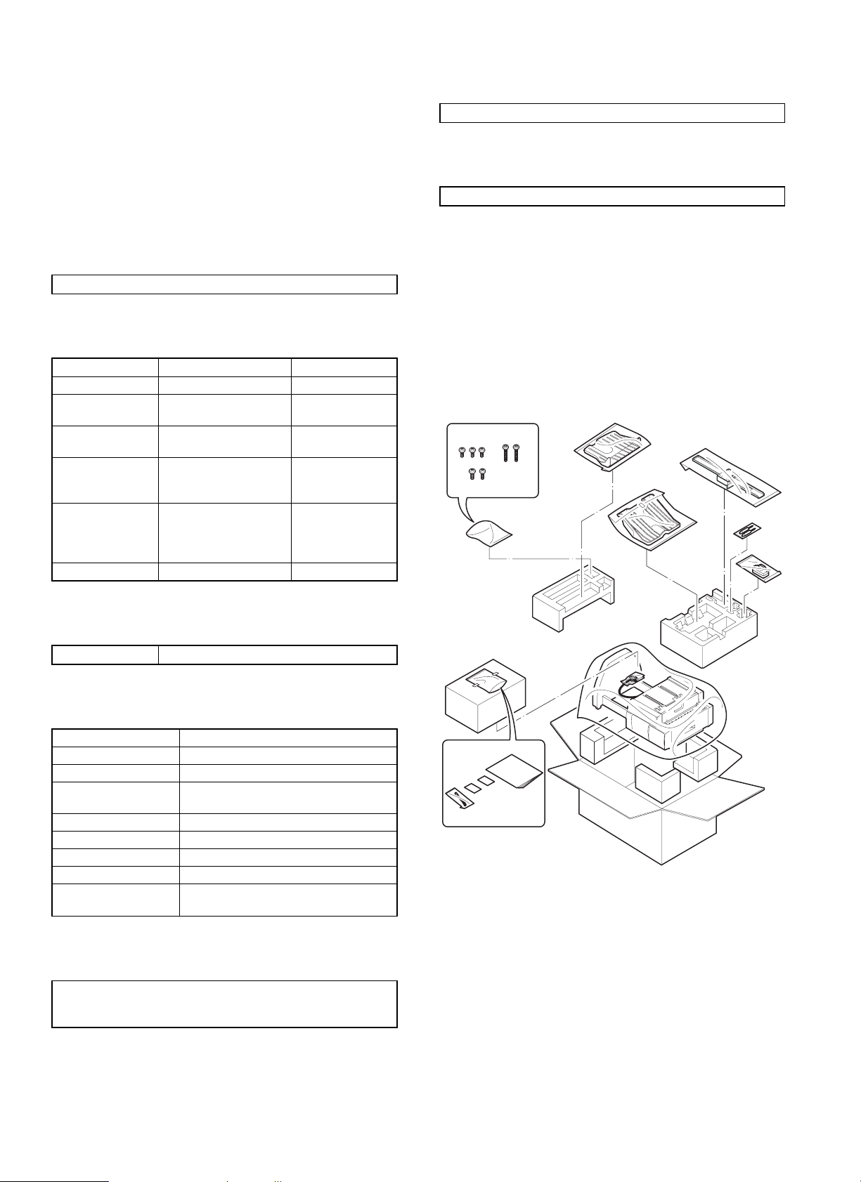
1. Unpacking
For unpacking, refer to the figure below.
3. Lift tray section
Offset amount 15mm, A4 35mm: B5 24mm: 8.5 ´ 11
4. Staple section
Storing system Face up
Stapling system Flat clinch
Stapling capacity 30 sheets (80g/m
Applicable size AB series: A4, B5
Inch series: 8 1/2
Alignment Max. shift width: 1mm
Stapling reference One position (front)
Staple supply system Cartridge system (5000 pcs.)
Staple Common with AR-SS1, SF-S54
Detection Detection of no staple/no cartridge/no
stapler
2
)
´ 11
5. External dimensions
457mm (W) ´ 518mm (D) ´ 820mm (H)
552mm (W)
extended)
´ 518mm (D) ´ 866mm (H)(with the upper tray
1 – 1
Page 4

2. Installation
Before installation, check that the following parts are included in the
package.
Parts included
1. Attach the connecting plate to the finisher.
Insert the connecting plate into the lower part of the finisher and
secure it using two screws A.
Tray 2: 1
Connecting plate: 1
Lock plates: 2
Positioning screws: 2
Screws A: 3
Screws B: 2
Exit tray: 1
Paper holder lever: 1
Stapling position label A: 1
Stapling position label B: 1
Screws C: 2
Unplug the copier’s power cord before carrying out
the following procedure.
Carry out the following steps before installing the
AR-FN2.
1. Pull out the exit unit of the copier until it stops.
2. Remove the two exit area cover fixing screws and remove the exit
area cover.
3. Remove the two transport springs that are attached to the exit
paper guide.
4. Store the two removed transport springs by hanging on the exit
unit front frame (position in Fig. 1).
5. Reattach the exit area cover to its original position and secure it
using two fixing screws.
6. Insert the exit unit into the copier.
Exit unit
Exit area cover
Fixing screw
Fixing screw
Screws A
Connecting plate
2. Attach the paper holder lever.
Attach the paper holder lever by inserting it into the mounting location
of the finisher as shown in the figure.
Paper holder lever
3. Attach the exit tray and tray 2.
Insert tray 2 securely into the tray mounting stand and secure it using
one screw A. Then attach the exit tray to the finisher by inserting boss
at (1) first.
Screw A
Exit tray
Tray 2
(2)
(1)
[Fig. 1]
Transport spring
1 – 2
Page 5
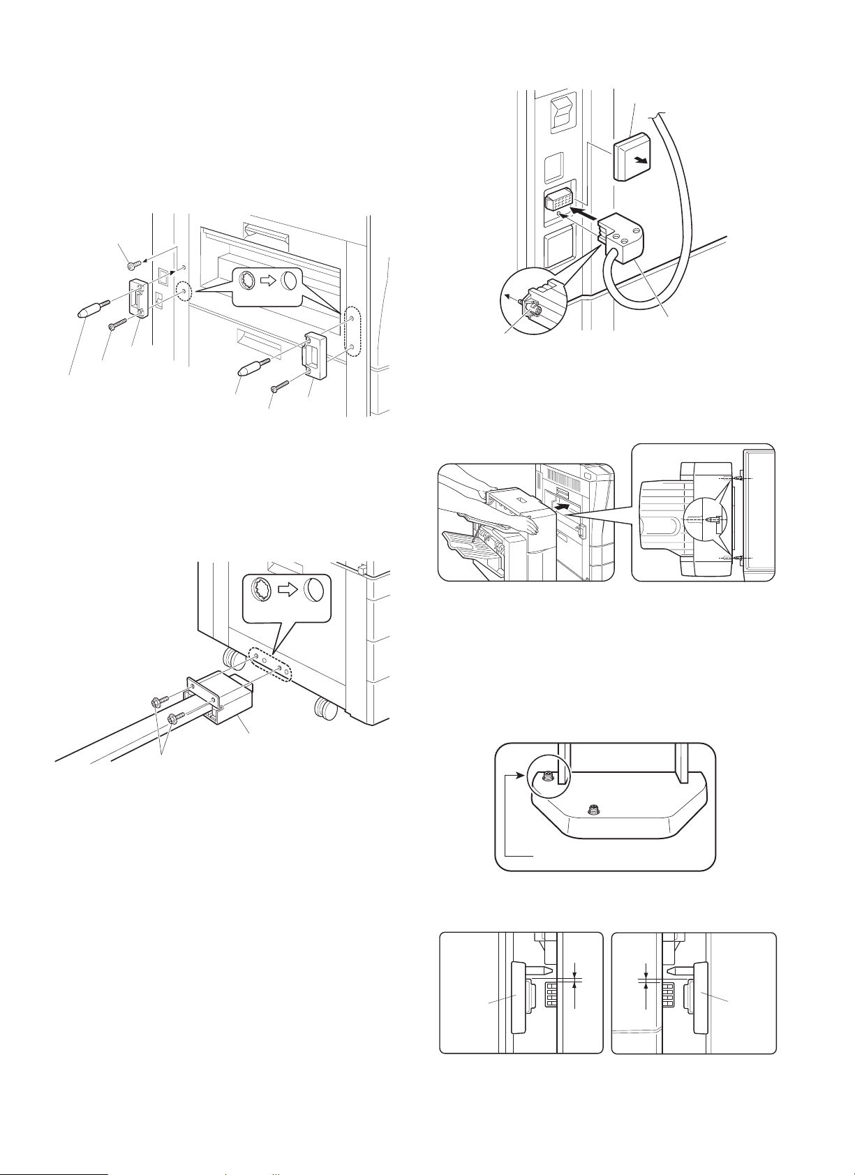
4. Attach the lock plates.
Cut out the three lock plate mounting holes on the copier using a
Phillips screwdriver or the like and remove the burrs using a flat-blade
screwdriver or the like.
Then remove the screw from the left cabinet of the copier and secure
the lock plates to the copier as shown in the figure using screws B
(one for each plate) and positioning screws (one for each plate). (Be
careful about the orientation of the lock plates.)
Screw
Mounting holes
Lock plate
Screw B
Positioning screw
Positioning screw
Screw B
Lock plate
5. Connect the finisher with the copier.
Cut out the two mounting holes at the lower part of the desk (leftmost
hole and third hole from the left) using a Phillips screwdriver or the
like and remove the burrs using a flat-blade screwdriver or the like.
Secure the mounting plate that is attached to the finisher connecting
plate to the lower part of the desk using two screws C.
Connector cover
Screw
Connector
7. Check and adjust the height of the finisher.
Move the finisher toward the copier, and check and adjust the height
so that the guide pin of the copier is inserted smoothly into the
positioning hole of the finisher.
Mounting holes
Mounting plate
Screws C
6. Connect the finisher connector.
Cut the connector cover for connection of the finisher relay harness
connector on the copier using nippers.
Then connect the finisher relay harness connector to the connector
on the copier and secure the connector by tightening the screw on
the connector.
· Since adjustment has been made at shipping, this adjustment
is basically not needed. If the guide pin should not be inserted
smoothly, adjust the height using the following procedure.
<1> Push the finisher into the copier.
Then, rotate the adjusting screw on the rear side of the finisher
lower part (Fig. 1) so that length b of the lock plate and lock
pawl on the rear side is within
the lock plate and lock pawl on the front side.
Adjusting screw
Lock plate
± 0.5 mm in relation to length a of
[Fig. 1]
b
a
Lock plate
1 – 3
Page 6
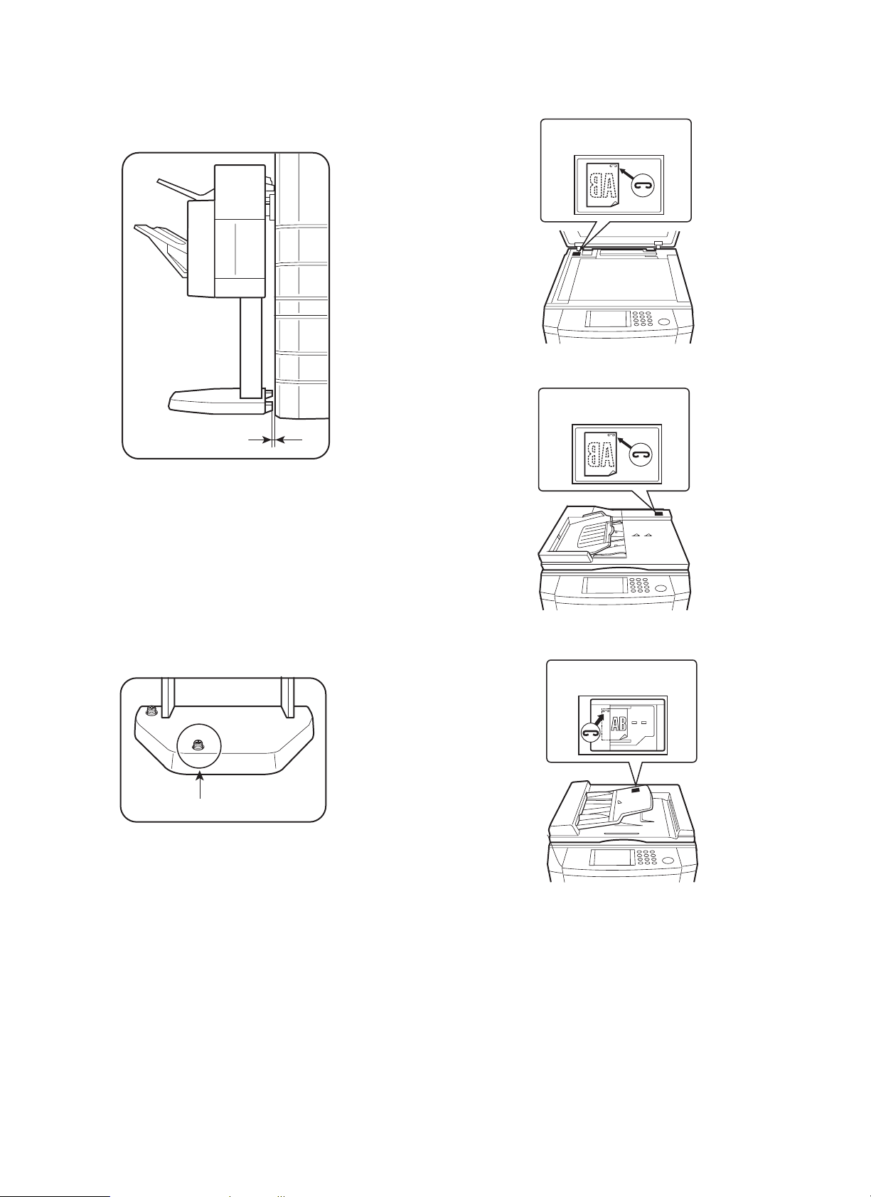
<2> Push the finisher into the copier.
At this time, check to see if the clearance between the lower
part of the finisher and the copier is approximately 1 mm (small
clearance).
Approximately 1 mm
If the finisher touches the copier or the clearance is too large:
Adjust the clearance by rotating the adjusting screw that is attached
to the paper exit side of the lower part of the finisher (Fig. 2).
· If the finisher touches the copier or the finisher is not locked:
Rotate the adjusting screw clockwise so that the clearance between the lower part of the finisher and the copier is approximately
1 mm.
· If the clearance is too large:
Rotate the adjusting screw counter-clockwise so that the clearance
between the lower part of the finisher and the copier is approximately 1 mm.
8. Stick a stapling position label.
For document cover
Stapling position label A
For SPF
Stapling position label A
For ADF/RADF
Stapling position label B
Adjusting screw
[Fig. 2]
1 – 4
Page 7
Insert the power plug of the copier to an outlet, turn
the power switch to the "ON" position and then
perform the following procedure.
Finisher operation check
· Check the operation in the staple mode.
Make 10 copies in the staple mode and check that the copies are
stapled properly.
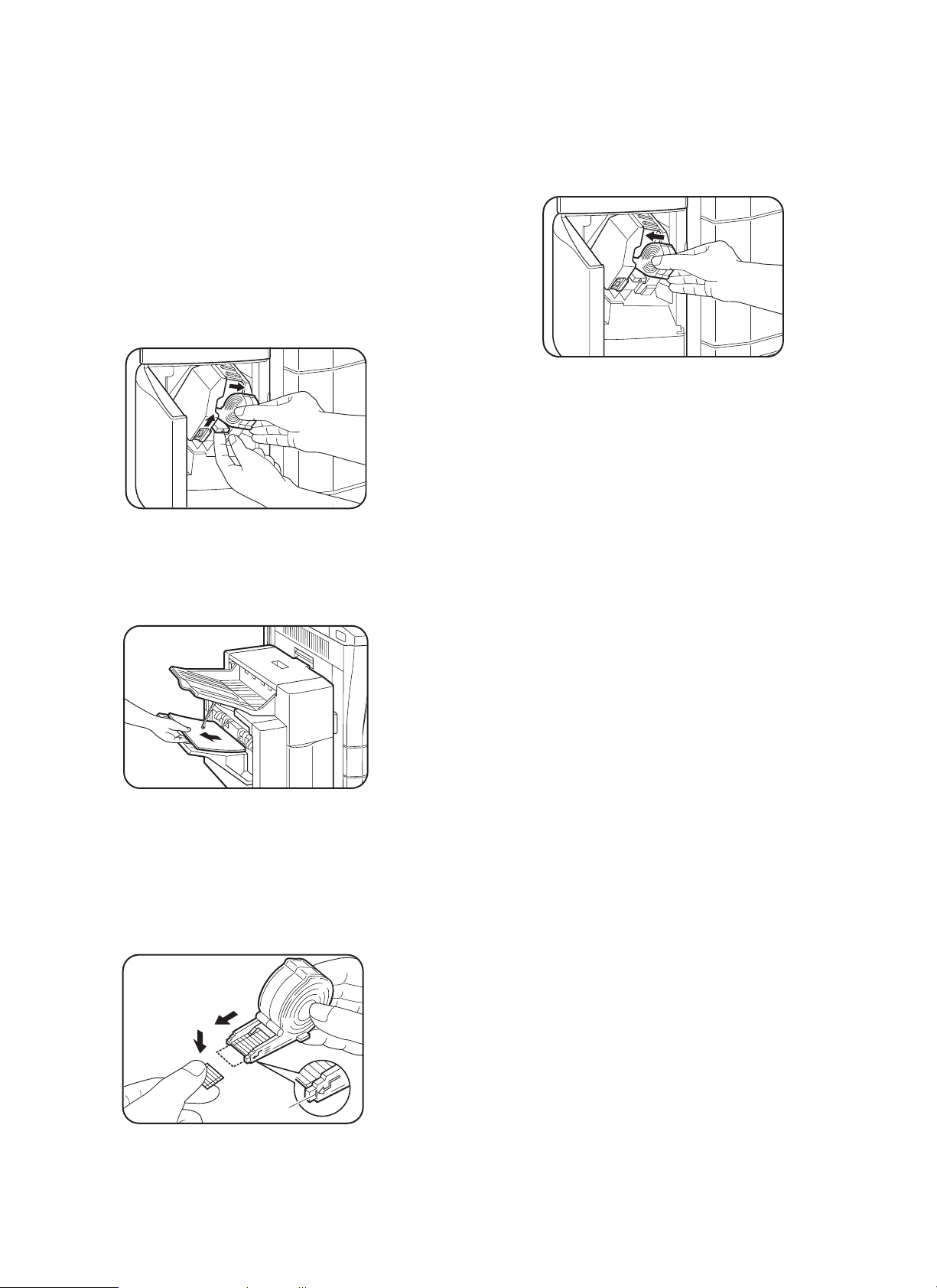
If the copies are not stapled at this time, use the following procedure to feed staples to the tip.
1. Open the stapler cover of the finisher.
2. Remove the staple cartridge.
Raise the staple cartridge release lever of the stapler unit to remove the staple cartridge.
5. Set the staple cartridge.
Open the stapler cover of the finisher and set the staple cartridge
in the stapler unit.
Insert the cartridge securely until it clicks.
Close the stapler cover.
Installation of the finishe r is now com plete.
3. Close the stapler cover of the finisher and remove the copies.
After removing the staple cartridge, close the stapler cover of the
finisher.
Then remove the copies from the finisher.
4. Check the staple cartridge.
Check that the first staple is at the STAPLE TEAR line of the
cartridge before setting the cartridge.
· If the first staple does not reach the STAPLE TEAR line, pull it
to the line.
· If the first staple protrudes past the STAPLE TEAR line, tear
the staples and align the first staple with the line.
(2)
(1)
STAPLE
TEAR line
1 – 5
Page 8
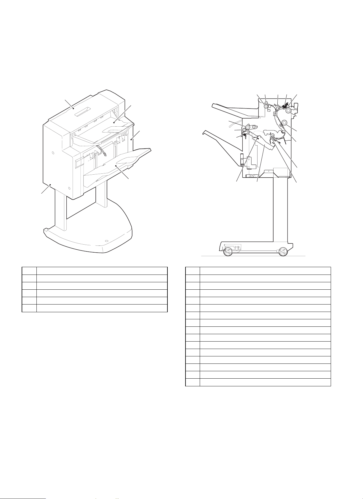
[4] EXTERNAL VIEW AND INTERNAL
STRUCTURE
1. External parts
1
2
2. Rollers, flapper, etc.
1234
15
4
5
3
6
7
5
8
9
14
13
12
11
10
No. Part name
1 Top cover
2 Rear cover
3 Front cover
4 Tray
5 Lift tray
No. Part name
1 Paper in sensor lever
2 Flapper
3 Paper exit/reverse follower roller
4 Paper exit/reverse roller
5 Bundle roller
6 Push roller
7 Paper exit sensor lever
8 Alignment tray sensor lever
9 Alignment lever
10 Intermediate tray paper exit follower roller
11 Intermediate tray paper exit roller
12 Paper transport follower roller
13 Paper transport roller
14 Finisher inlet roller
15 Finisher inlet follower roller
4 – 1
Page 9
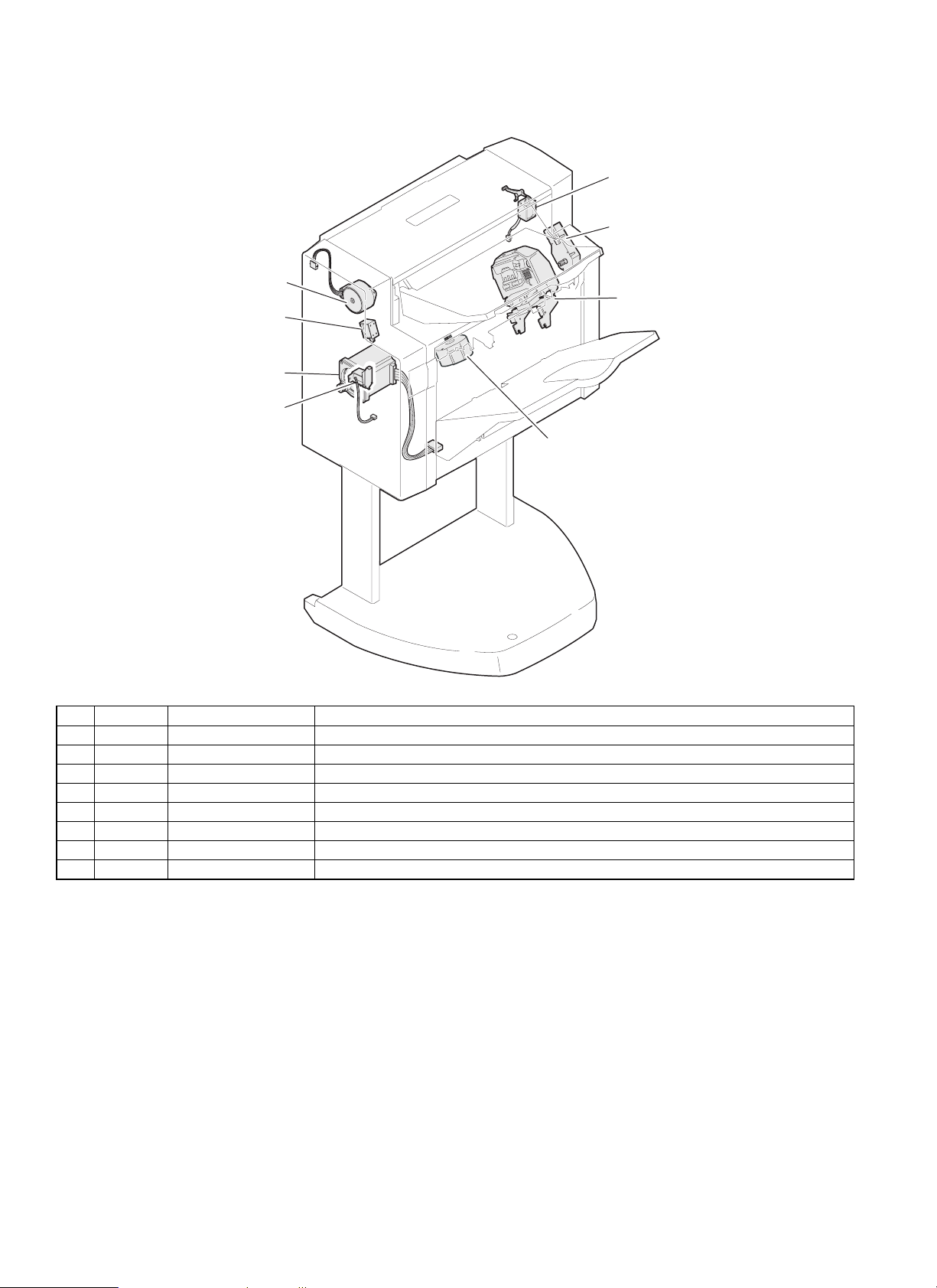
3. Motors, solenoids
2. DRM
6. PRSL
3. TMM
5. SU
8. BS
1. DTM
7. PDS
4. DSM
No. Code Name Function
1 DTM Transport motor Drives paper through the transport path.
2 DRM Reverse motor Discharges paper to the upper tray or reverses paper and sends to the lower transport path.
3 TMM Bin shift motor Moves the accumulation tray up and down.
4 DSM Alignment motor Drives the alignment plate in alignment operation.
5 SU Stapler Staples a paper bundle.
6 PRSL Reverse solenoid Sends paper directly to the lower transport path when turned on.
7 PDS Paddle solenoid Rotates the paddle when turned on.
8 BS Boomerang solenoid Rotates the boomerang when turned on.
4 – 2
Page 10
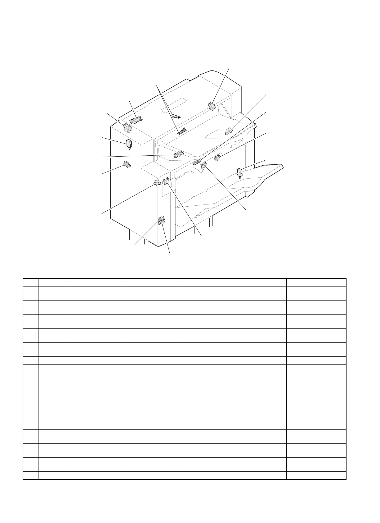
4. Sensors, switches
12. ULS2
14. PRS
10. UCS
15. SSW
1. JTES
11. ULS1
5. SBHPS
3. PIS
6. FSS
7. TMMRS
4. BES
8. PLS
16. CSW
9. AS
2. BRS
13. TLS
No. Code Name Type Function, operation Contact, output
1 JTES Process tray paper
exit sensor
2 BRS Boomerang rotation
sensor
3 PIS Transport inlet sensor Photo interrupter HIGH when the paper lead edge is sent to the
4 BES Bundle exit sensor Photo interrupter Detection of paper on the process tray HIGH when paper is
5 SBHPS Paper alignment plate
home position sensor
6 FSS Full stack sensor Photo interrupter Accumulation tray full detection HIGH when paper is full.
7 TMMRS Tray rotation sensor Photo interrupter Tray lift motor rotation detection Pulse output
8 PLS Paper level sensor Photo interrupter Paper level detection in the accumulation tray HIGH when paper is
9 AS Accumulation tray
sensor
10 UCS Upper cover sensor Photo interrupter Upper transport path cover open/close
11 ULS1 Unit lock sensor 1 Photo interrupter Lock detection with the copier (Rear side) LOW when locked.
12 ULS2 Unit lock sensor 2 Photo interrupter Lock detection with the copier (Front side) LOW when locked.
13 TLS Tray limit sensor Photo interrupter Accumulation tray lower limit detection HIGH when the lower
14 PRS Paper reverse sensor Transmission sensor HIGH when paper is fed in front of the fixed
15 SSW Set switch Micro switch Lower transport path cover open/close
16 CSW Cover switch Micro switch Stapler cover open/close detection LOW when closed.
Photo interrupter HIGH when the paper lead edge is transported
to the process tray tip.
Photo interrupter HIGH when the boomerang is rotating in the
accumulation tray exit section.
finisher.
Photo interrupter Detection of the home position of the alignment
plate on the process tray
Photo interrupter Paper presence detection i the accumulation
tray
detection
tray.
detection
HIGH when paper is
detected.
HIGH when the
boomerang is rotating.
HIGH when paper is
detected.
detected.
HIGH when stopping at
the home position.
detected.
LOW when paper is
detected.
LOW when closed.
limit is detected.
LOW when paper is
detected.
LOW when closed.
4 – 3
Page 11
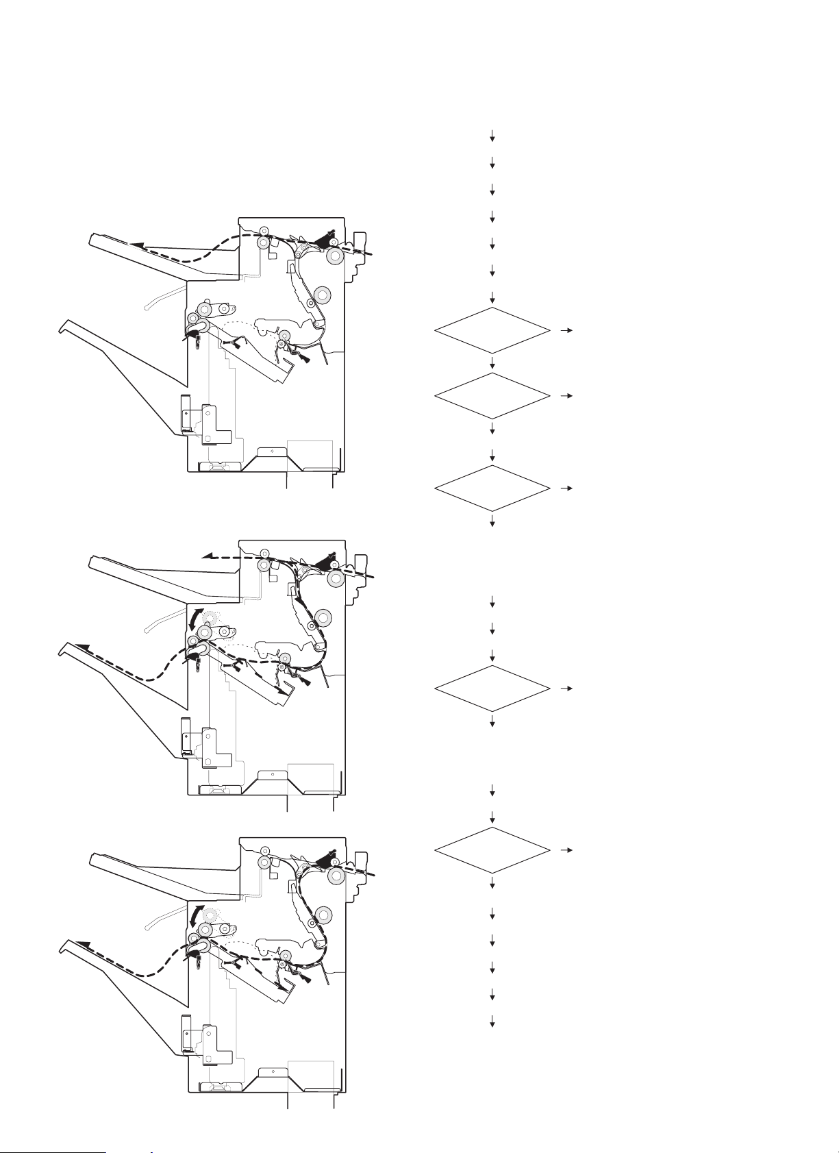
[5] OPERATIONAL DESCRIPTIONS
1. Paper transport path
The paper transport path is shown in the figure below.
(The dotted line ( - - - - - ) shows the paper transport path.)
<Non-job mode: Discharged to the top tray.>
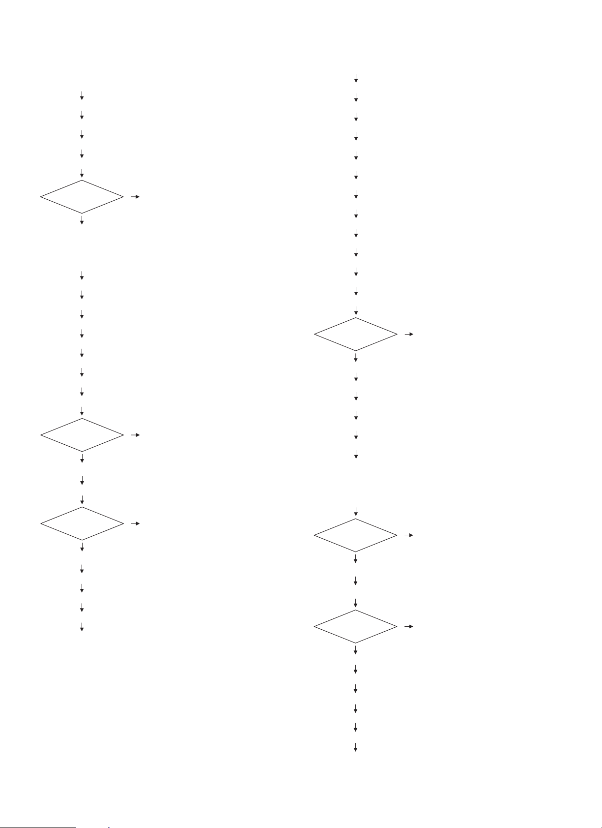
2. Operation process
START
STEP 01 Copier print start ON
STEP 02 Operation mode command received
STEP 03 JOB_START command received
STEP 04 Transport motor start
STEP 05 Paper exit operation specify command 2 received
STEP 06 Copier paper exit information command received
<Long job/Staple mode: Discharged to the job tray.>
1 Reversing paper
Paper exit tray
Paper exit to the offset tray
Reversing
NO
STEP 07 Reverse solenoid ON
Paper exit mode
Staple mode
Go to (3)
Paper exit to the top tray
Go to (1)
YES
Go to (2)
Normal mode
Go to (4)
(1)
STEP 08 Finisher inlet sensor ON
STEP 09 Finisher inlet sensor OFF
YES
Next paper
Go to STEP 05
2 Without reversing
5 – 1
NO
Go to STEP 57
(2)
STEP 10 Finisher inlet sensor ON
Reversing
YES
STEP 11 Reverse motor forward rotation ON
STEP 12 Reverse sensor ON
STEP 13 Inlet sensor OFF
STEP 14 Reverse sensor OFF
STEP 15 Reverse motor forward rotation OFF
Go to STEP 16
NO
Go to STEP 20
Page 12
(3)
STEP 16 Reverse motor reverse rotation ON
STEP 17 Reverse sensor ON
STEP 18 Reverse sensor OFF
STEP 19 Reverse motor reverse rotation OFF
STEP 20 Process tray paper exit sensor ON
Offset
With offset
Go to (4)
Without offset
Go to STEP 24
(4)
STEP 21 Process tray paper exit sensor OFF
STEP 22 Alignment motor ON
STEP 23 Alignment motor OFF
STEP 24 Boomerang solenoid ON
STEP 25 Boomerang solenoid OFF
STEP 26 Boomerang rotation sensor OFF
STEP 27 Boomerang rotation sensor ON
STEP 34 Inlet sensor ON
STEP 35 Inlet sensor OFF
STEP 36 Process tray paper exit sensor ON
STEP 37 Paddle solenoid ON
STEP 38 Paddle solenoid OFF
STEP 39 Process tray paper exit sensor OFF
STEP 40 Alignment motor ON
STEP 41 Alignment motor OFF
STEP 42 Paddle solenoid ON (One turn)
STEP 43 Paddle solenoid OFF
STEP 44 Paddle solenoid ON (Two turns)
STEP 45 Paddle solenoid OFF
NO
Staple treatment
YES
STEP 46 Staple process
STEP 47 Boomerang solenoid ON
STEP 48 Boomerang solenoid OFF
Go to STEP 05
Paper level
sensor
ON
STEP 28 Bin shift motor ON
STEP 29 Bin shift motor OFF when paper level sensor OFF
Next paper
NO
STEP 30 Boomerang solenoid ON
STEP 31 Boomerang solenoid OFF
STEP 32 Boomerang rotation sensor OFF
STEP 33 Boomerang rotation sensor ON
Go to STEP 57
OFF
Go to STEP 29
YES
Go to STEP 05
STEP 49 Boomerang rotation sensor OFF
STEP 50 Boomerang rotation sensor ON
Go to (5)
(5)
Paper level
sensor
ON
STEP 51 Bin shift motor ON
STEP 52 Bin shift motor OFF when paper level sensor OFF
Next paper
NO
STEP 53 Boomerang solenoid ON
STEP 54 Boomerang solenoid OFF
STEP 55 Boomerang rotation sensor OFF
OFF
Go to STEP 52
YES
Go to STEP 05
5 – 2
STEP 56 Boomerang rotation sensor ON
STEP 57 Transport motor stop
END
Page 13
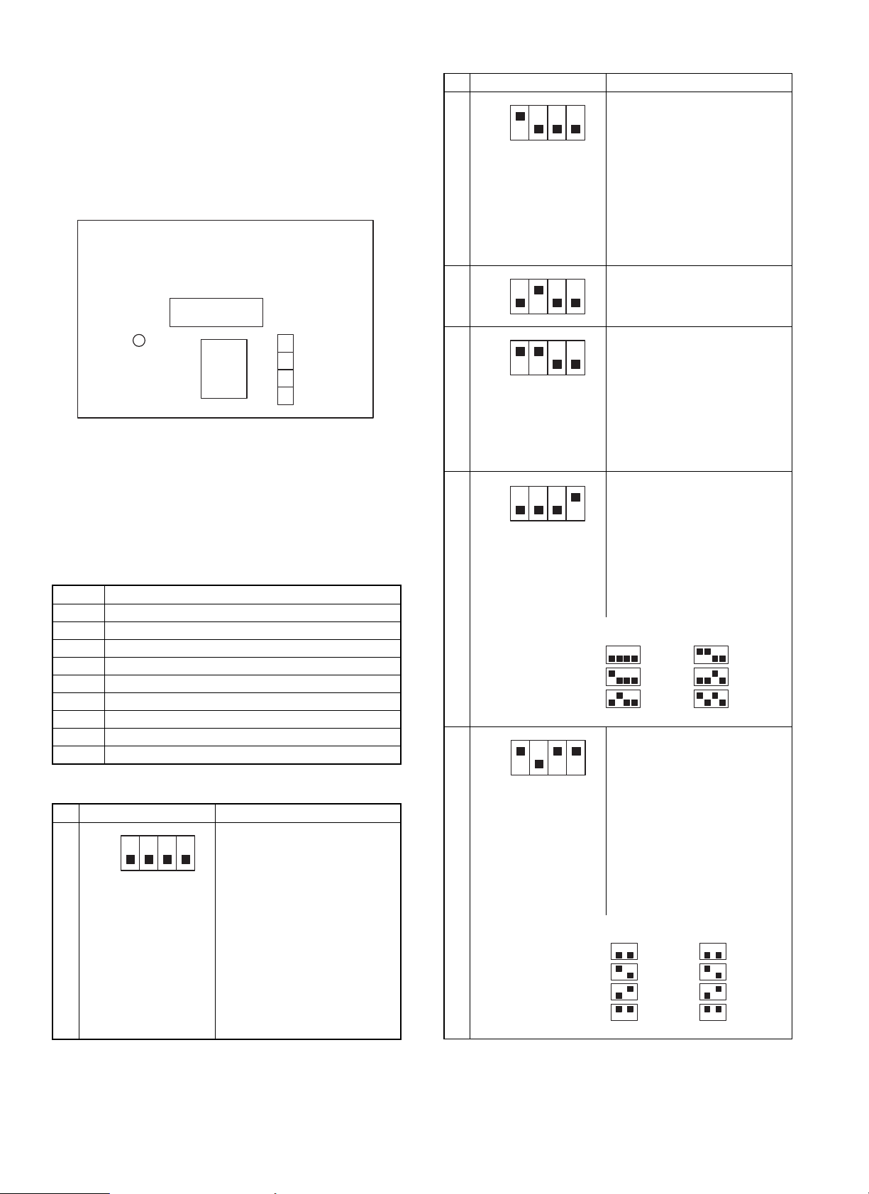
[6] TEST MODE AND SETTING DIP
SWITCHES
1. Position of dip switches
The dip switches are located on the main PWB as shown in the figure
below.
ROM
LED
CPU
2. Setting dip switches
(1) Selecting test modes
Select the test mode type using the dip switches. Holding down the
push switch, turn on the power to get in the selected test mode. After
that, change over the dip switches and press the push switch as
necessary.
1 Load individual operation check mode 1
2 Load individual operation check mode 2
3 Staple operation check mode
4 Alignment plate stop position check mode
5 Non-job tray exit mode
6 No-reverse offset exit mode
7 Reverse offset exit mode
8 Staple exit mode
9 Reverse offset aging mode
10 Staple aging mode
(2) S e ttin g te s t mode
1 2 3 4 Description
Loaded test mode 1
ON
OFF
1
In this test mode, each actuator is
activated and deactivated every
time the push switch is pressed.
The following operations is
repeated:
Reverse SOL
Puddle SOL
Discharge SOL
Transfer motor
Stack tray motor
DIPSW
¯
¯
¯
¯
1 2 3 4 Description
Loaded test mode 2
ON
OFF
In this mode, each actuator is
activated and deactivated every
time the push switch is pressed.
The following operations are
2
repeated:
Reverse motor
(forward rotation)
¯
Reverse motor
(reverse rotation)
Matching plate
Stapler operation check mode
ON
3
OFF
In this mode, the stapler operates
once every time the push switch is
pressed.
Matching plate stop position
ON
OFF
check mode
In this mode, the matching plate
stops at the paper matching
4
position and returns to its home
position every time the push
switch is pressed.
Staple discharge JOG discharge
® Letter ® B5 ® A4 ® Letter
A4
® B5
Non-job tray discharge mode
ON
OFF
After turning on the machine in a
test mode, set to this mode with
the dip switches. Pressing the
push switch sets paper size and
performs initial operation. After
the completion of the initial
operation, it becomes possible to
5
pass paper. The settings of the
dip switches are as follows:
1
ON
OFF
234
A3_T
A4_Y
A4_T
ON
OFF
1
234
LETTER_Y
LETTER_T
EXE_Y
No-reversion offset discharge
ON
OFF
mode
After turning on the machine in a
test mode, set to this mode with
the dip switches. Pressing the
push switch sets paper size and
the number of sheets to be
processed and performs initial
operation. After the completion of
the initial operation, it becomes
6
possible to pass paper. The
settings of the dip switches are as
follows:
ON
OFF
12
A4
LETTER
B4
EXE
ON
OFF
34
2pls
5pls
10pls
30pls
6 – 1
Page 14
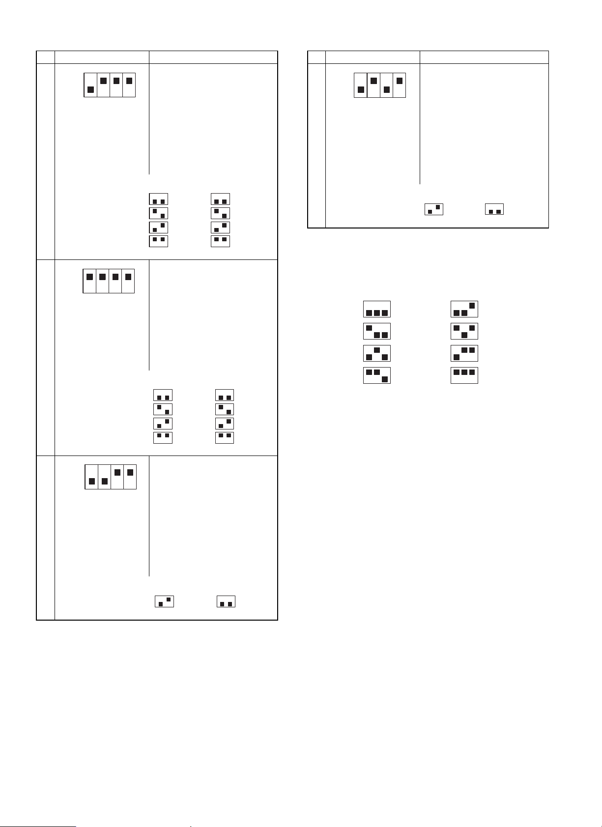
1 2 3 4 Description
Reversion offset discharge mode
ON
OFF
After turning on the machine in a
test mode, set to this mode with
the dip switches. Pressing the
push switch sets paper size, the
number of sheets to be processed
and performs initial operation.
After the completion of the initial
operation, it becomes possible to
7
pass paper. The settings of the
dip switches are as follows:
10
1 2 3 4 Description
Staple aging mode
ON
OFF
After turning on the machine in a
test mode, set to this mode with
the dip switches. Pressing the
push switch sets paper size to
Letter and the number of sheets
to be processed to 2, and
performs initial operation. After
the completion of the initial
operation, aging operation starts.
The settings of the dip switches
are as follows:
ON
OFF
12
A4
LETTER
B4
EXE
ON
OFF
34
2pls
5pls
10pls
30pls
ON
OFF
12
LETTER_Y
34
2pls
(3) When DIP SW4 is turned on, offset exit paper is
reversely discharged. (Used to check the
Staple discharge mode
ON
OFF
After turning on the machine in a
test mode, set to this mode with
the dip switches. Pressing the
push switch sets paper size, the
number of sheets to be processed
and performs initial operation.
After the completion of the initial
operation, it becomes possible to
8
pass paper. The settings of the
dip switches are as follows:
ON
OFF
12
A4
LETTER
B4
EXE
ON
OFF
34
2pls
5pls
10pls
30pls
reversing operation in the printer mode.)
1
ON
OFF
23
2pls
4pls
6pls
8pls
ON
OFF
1
23
10pls
12pls
14pls
16pls
(4) All the dip switches are factory set to OFF.
Reversion offset aging mode
ON
OFF
After turning on the machine in a
test mode, set to this mode with
the dip switches. Pressing the
push switch sets paper size to
Letter and the number of sheets
to be pressed to 2, and performs
9
initial operation. After the
completion of the initial operation,
aging operation starts. The
settings of the dip switches are as
follows:
ON
OFF
12
LETTER_Y
34
2pls
6 – 2
Page 15

[7] DISASSEMBLY AND ASSEMBLY
(Note)
· This chapter describes mainly the disassembly procedures. For
assembly procedures, reverse the disassembly procedures.
· For disassembly, remove the parts in the sequence of numbering
in the figure.
1. Upper cover ass’y
1)
2)
3)
11)
9)
7)
8)
12)
10)
10)
13)
4)
6)
5)
7 – 1
Page 16

2. Tray cover ass’y
Remove the front and the rear covers.
7)
5)
2)
5)
6)
5)
1)
3. Cover top
3)
1) Remove the outer cover.
3)
4)
(2)
(3)
7 – 2
(1)
(1)
(4)
Page 17

4. Flapper and reverse motor
1) Remove the outer cover.
2) Remove the cover top assembly (with main cover).
Match the prsjection with the
groove
(A)
A
(5)
(2)
(A)
(3)
(1)
5. Cover guide assembly
1) Remove the outer cover.
2) Remove the cover top assembly (with main cover).
(6)
(4)
(7)
(2)
(1)
(3)
(5)
(4)
7 – 3
Page 18

6. Matching tray unit
1) Remove the outer cover.
2) Remove the cover top assembly (with main cover).
5)
4)
3)
4)
3)
7)
6)
1)
3)
2)
7. Guide paddle
8)
1) Remove the outer cover.
2) Remove the front and rear cover masks and flapper.
3) Remove the paper reversion/discharge guide bracket.
(3)
(4)
(5)
(6)
(5)
(7)
(2)
(1)
7 – 4
Page 19

8. Control PWB and large gear
1) Remove the outer cover.
2) Remove the connector from the control PWB.
(6)
(4)
(3)
(5)
(8)
(7)
(1)
(1)
(1)
(2)
(1)
(13)
9. Bundle discharge roller
1) Remove the outer cover.
2) Remove the large gear.
3) Remove the tray’s side cover.
(2)
(1)
(7)
(8)
(9)
(10)
(11)
7 – 5
(12)
(14)
(6)
(5)
(14)
(4)
(3)
(1)
Page 20

[8] ADJUSTMENTS
1. De-curler roller gap adjustment
Adjustment procedures
1) Remove the paper entry guide 1) and paper entry guide lever 2).
2) Push the adjustment plate 3) fully to the end of the adjustment
margin in the arrow direction, and fix it with screw 4).
There are two adjustment positions for adjustment plate 3). Adjust
in the same manner. As a result, decolor roller 5) and roller shaft
6) are bent in 2.0mm.
(6)
(5)
(3)
(1)
(2)
(4)
Roller pushing amount: 0mm Roller pushing amount: 1mm Roller pushing amount: 2mm
(Note) When replacing de-curler roller 5) and roller shaft 6), be sure
to perform the above adjustment in advance.
8 – 1
Page 21

[9] MAINTENANCE
Note: Before performing maintenance, be sure to disconnect the power plug from the power outlet.
Maintena n c e lis t
(Content) ★: Lubricate | : Clean ü: Adjust ▲: Replace ✕: Check (Clean, replace, adjust according to necessity.)
Part name 80K 160K 240K 320K 400K 480K Same cycle hereinafter
A Reverse sensor (Transmission type)
1 Finisher inlet roller
2 Paper reverse/exit roller ||||||
B
3 Paper transport roller ||||||
4 Intermediate tray exit roller ||||||
5 Bundle exit roller ||||||
C Timing belt ✕✕✕✕✕ü
1 Torque limiter
2 Torque limiter ★★★★★▲
D
3 Torque limiter ★★★★★▲
4 Torque limiter ★★★★★▲
1 Discharge brush (Upper tray paper exit section)
E
2 Discharge brush (Intermediate tray section) ✕✕✕✕✕▲
F Staple unit Replace after operations of 100 thousand times.
||||||
||||||
★★★★★▲
✕✕✕✕✕▲
A. Reverse sensor
(1)
(1)
9 – 1
(1)
Page 22

B. Rollers
(1)
(3)
(4)
(2)
(5)
(2)
(4)
(5)
(1)
(3)
(5)
(5)
(5)
9 – 2
Page 23

C. Timing belt
D. Torque lim ite r
(4)
(2)
(1)
(3)
9 – 3
Page 24

E. Discharge brush
(1)
F. Staple unit
(2)
(1)
(2)
9 – 4
Page 25

[10] TROUBLESHOOTING
1. Trouble code
Trouble code
Main
code
Sub
code
F1 00 Content Finisher communication trouble
Detail Communication line test error occurs
when power is turned on or after the exit
of a simulation mode.
Improper communication with sorter
Cause Improper connection or broken wire of
Check
and
remedy
01 Content Finisher 2 alignment section trouble
Detail Alignment plate shift trouble
Cause Motor lock
Check
and
remedy
04 Content Finisher elevater lower limit detected
Detail Elevater has exceeded lower limit.
Cause Sensor defective
Check
and
remedy
05 Content Stack tray sensor abnormality
Detail Stack tray sensor turns on in abnormal
Cause Sensor defective
Check
and
remedy
connector or harness between copier
and Finisher
Finisher control PWB defective
Control PWB (PCU) defective
Malfunction due to noise
Clear by turning the power supply
OFF/ON.
Check communication line connector and
harness.
Replace Finisher control PWB or PCU
PWB.
Motor rpm abnormality
Motor overcurrent
Finisher control PWB trouble
Check the jogger motor operation with
SIM 3-3.
Finisher control PWB defective
Check sensor with SIM3-2.
combination.
Finisher control PWB defective
Check sensor with SIM3-2.
Description
Trouble code
Main
code
Sub
code
F1 10 Content Staple unit operation trouble
Detail Staple operation trouble
Cause Motor lock
Check
and
remedy
11 Content Boomerang rotation
Detail Boomerang solenoid
Cause Boomerang solenoid operation trouble
Check
and
remedy
14 Content Stack tray abnormality
Detail Stack tray control sensor abnormality
Cause a) The paper level sensor or the full stack
Check
and
remedy
15 Content Stack tray motor lock
Detail Elevator motor trouble
Cause Motor lock
Check
and
remedy
Motor rpm abnormality
Motor overcurrent
Finisher control PWB trouble
Check the staple motor operation with
SIM 3-3.
Boomerang rotation sensor abnormality
Motor rpm abnormality
Motor overcurrent
Finisher control PWB trouble
Check the with SIM 3-2.
b) When the tray is lifted, the stack tray is
Check the sensors with SIM 3-2.
Check the elevator motor operation with
SIM 3-3.
Motor rpm abnormality
Motor overcurrent
Finisher control PWB trouble
Check the elevator motor operation with
SIM 3-3.
Description
sensor are not turned on in a certain
time after starting the tray.
locked.
10 – 1
Page 26

2. Troubleshooting
Trouble Cause Troubleshooting and treatment
(1) When the main switch of
the copier is turned on,
it does not work at all.
(2) The transport motor
does not operate.
(3) The reverse motor does
not operate.
(4) The alignment motor
does not operate.
(5) The accumulation tray
motor does not operate.
(6) The boomerang
solenoid does not
operate.
(7) The reverse solenoid
does not operate.
(8) The paddle solenoid
does not operate.
(9) The copier display
shows "Finisher paper
jam."
(10) The copier display
shows "Finisher not
connected."
(11) The copier display
shows Finisher cover
open.
(12) Paper is stopped
during exit operation
1. Contact trouble with the copier Check contact of each connector.
2. Contact trouble of the connector
pin of the connection wire with the
copier
3. Stapler section cover switch, lower
transport path set switch trouble
4. Control PWB trouble If DC24V and DC5V are inputted from the copier and LED on the control
1. Motor connector pin contact trouble
Make a conduction test between connectors and replace, if not
conducting.
Make a conduction test between switches, and replace if necessary.
PWB does not blink and 24V is ont supplied to CN8-1, replace the control
PWB.
· Check contact of the connector, and repair if necessary.
· Make a conduction test of connector pins and replace if not conducting.
2. Motor coil disconnection Make a conduction test between coils and replace the motor if ont
conducting.
3. Control PWB trouble If the motor does not operate in the load operation mode, replace the
control PWB.
1. Solenoid connector pin contact
trouble
2. Solenoid coil disconnection Make a conduction test between coils, and replace the solenoid if not
3. Control PWB trouble If the solenoid does not operate in the load operation mode, replace the
1. Paper jam Visually inspect and remove the jam.
2. Transport entry port sensor trouble Measure the voltage at TP41 on the control PWB. If it is not 0V at sensor
3. Treatment tray exit sensor trouble Measure the voltage at TP56 on the control PWB. If it is not 0V at sensor
4. Bundle exit sensor trouble Measure the voltage at TP58 on the control PWB. If it is not 0V at sensor
5. Paper reverse sensor trouble Measure the voltage at TP22 on the control PWB. If it is not 0V at sensor
6. Sensor connector pin contact
trouble
7. Control PWB trouble When each sensor is turned on/off, the sensor level is changed but the
1. Finisher not connected Connect the finisher.
2. Unit lock sensor 1 trouble Measure the voltage at TP20 on the control PWB. If it is not 0V at when
3. Unit lock sensor 2 trouble Measure the voltage at TP46 on the control PWB. If it is not 0V when
6. Sensor connector pin contact
trouble
7. Control PWB trouble When each sensor is turned on/off, the sensor level is changed but the
1. Upper cover open Visually inspect and remove the cover.
2. Upper cover sensor trouble Measure the voltage at TP17 on the control PWB. If it is not 0V at sensor
3. Sensor connector pin contact
trouble
4. Control PWB trouble When each sensor is turned on/off, the sensor level is changed but the
1. Boomerang rotation sensor trouble Measure the voltage at TP59 on the control PWB. If it is not 0V at sensor
2. Paper alignment home position
sensor trouble
3. Sensor connector pin contact
trouble
4. Control PWB trouble When each sensor is turned on/off, the sensor level is changed but the
· Check contact of the connector, and repair if necessary.
· Make a conduction test of connector pins, and replace if not
conducting.
conducting.
control PWB.
OFF and 5V at ON, replace the transport path entry port sensor.
OFF and 5V at ON, replace the treatment tray exit sensor.
OFF and 5V at ON, replace the bundle exit sensor.
OFF and 5V at ON, replace the paper reverse sensor.
Make a conduction test of connector pins, and replace the pin if not
conducting.
phenomenon is not changed, replace the control PWB.
coupling and 5V when not coupling, replace the unit lock sensor 1.
coupling and 5V when not coupling, replace the unit lock sensor 2.
Make a conduction test of connector pins, and replace the pin if not
conducting.
phenomenon is not changed, replace the control PWB.
OFF and 5V at ON, replace the transport path entry port sensor.
Make a conduction test of connector pins, and replace pins if not
conducting.
phenomenon is not changed, replace the control PWB.
OFF and 5V at sensor ON, replace the transport path entry port sensor.
Measure the voltage at TP23 on the control PWB. If it is not 0V at sensor
oFF and 5V at ON, replace the transport path entry sensor.
Make a conduction test of connector pins, and replace the pins if not
conducting.
phenomenon is not changed, replace the control PWB.
10 – 2
Page 27

Trouble Cause Troubleshooting and treatment
(13) The accumulation tray
does not stop at the
proper position.
1. Tray rotation sensor trouble Measure the voltage at TP5 on the control PWB. If it is not 0V at sensor
OFF and 5V at ON, replace the transport path entry sensor.
2. Full stack sensor trouble Measure the voltage at TP16 on the control PWB. If it is not 0V at sensor
OFF and 5V at ON, replace the transport path entry port sensor.
3. Tray limit sensor trouble Measure the voltage at Tp18 on the control PWB. If it is not 0V at sensor
OFF and 5V at ON, replace the transport path entry port sensor.
4. Paper surface sensor trouble Measure the voltage at TP47 on the control PWB. If it is not 0V at sensor
OFF and 5V at ON, replace the transport path entry port sensor.
5. Accumulation tray sensor trouble Measure the voltage at TP19 on the control PWB. If it is not 5V at sensor
OFF and 0V at ON, replace the transport path entry port sensor.
6. Sensor connector pin contact
trouble
Make a conduction test of connector pins, and replace pins if not
conducting.
7. Control PWB trouble When each sensor is turned on/off, the sensor level is changed but the
phenomenon is not changed, replace the control PWB.
10 – 3
Page 28

[11] CIRCUIT DESCRIPTIONS
1. Outline
This circuit controls document transport, reverse, alignment, stapling and discharge.
It is composed of a circuit which controls sensors, switches,and copier signals input, and a circuit which drives the motors and the solenoids, and
CPU, G/C and it peripheral circuits
2. Block diagram
Paper transport
Communication
circuit
Paper reverse
sensor input
circuit
Transport path
entry sensor input
circuit
Address bus
motor drive
circuit
Paper alignment
motor drive
circuit
Paper reverse
motor drive
circuit
Process tray paper
exit sensor input
circuit
Bundle exit sensor
inpout circuit
Accumulation tray
sensor input
circuit
Boomerang
rotation sensor
input circuit
Unit lock sensor 1
input circuit
Unit lock sensor 2
input circuit
Upper cover
sensor input
circuit
Paper alignment
home position
sensor input circuit
Paper level
sensor input
circuit
Data bus
DIP switch push
switch
rush current
limit circuit
+24V
Open/close
switch input
circuit
Power ON
reset circuit
Oscillation
circuit
11MHz
Bin shift motor
drive circuit
Boomerang solenoid
drive circuit
Reverse solenoid
drive circuit
Paddle solenoid
drive circuit
Staple motor
drive circuit
Current limit
circuit
Stapler home
position sensor
input circuit
Staple near end
sensor input circuit
Staple presence
sensor input circuit
Tray rotation
sensor input
ircuit
Tray limit sensor
input circuit
Full stack sensor
input circuit
Power circuit
11 – 1
Page 29

3. Operations
A. Sensor input circuit
[a] Transport path entry sensor (PIS)
PIS is a photo interrupter which integrates a light emitting diode and photo transistor. A document from the copier is detected by the lever-system
actuator. The light path is interrupted when document presence.
The signal is passed to the CPU (IC9-61 pin) through the noise filter of R13 and C17.
Logic of the signal inputted to the CPU: Document presence
R45 is the current limiting resistor of LED. R67 is the sensor load resistor.
Transport entry port
sensor
(PIS)
[b] Treatment tray exit sensor (JTES)
JTES is the sensor same as the transport entry port sensor (PIS). The document discharged to the treatment tray is detected by the lever-system
actuator. The light path is interrupted when document presence.
The signal is passed to the CPU (IC9-59 pin) through the noise filter of R14 and C18.
Logic of the signal inputted to the CPU: Document presence
R46 is the current limiting resistor of LED. R68 is the sensor load resistor.
® H, Document empty ® L
Transport entry port sensor input circuit
® H, Document empty ® L
Process tray paper
exit sensor
(JTES)
Process tray paper exit sensor input circuit
[c] Bundle exit sensor (BES)
BES is the sensor same as the transport entry port sensor (PIS).
The document on the treatment tray is detected by the lever-system actuator. The light path is interrupted when document is present.
The signal is passed to the CPU (IC9-56 pin) through the noise filter of R17 and C20.
Logic of the signal inputted to the CPU: Document present
R47 is the current limiting resistor of LED. R69 is the sensor load resistor.
Bundle exit sensor
(BES)
® H, Document empty ® L
Bundle exit sensor input circuit
11 – 2
Page 30

[d] Full stack sensor (FSS)
FSS is the sensor same as the transport entry port sensor (PIS).
The document full state on the treatment tray is detected by the douser liked with the tray movement. The light path is interrupted when document
full.
The signal is passed to the G/A (IC5-39 pin) through the noise filter of R1 and C3.
Logic of the signal inputted to the G/A: Document tray full detected
R39 is the current limiting resistor of LED. R52 is the sensor load resistor.
Full stack sensor
(FSS)
® H, Document tray full not detected ® L
Full stack sensor input circuit
[e] Tray limit sensor (TLS)
TLS is the sensor same as the transport entry port sensor (PIS).
The tray bottom (limit) is detected by the douser liked with the tray movement. The light path is interrupted when "Limit." The signal is passed to the
G/A (IC5-41 pin) through the noise filter of R4 and C6.
Logic of the signal inputted to the G/A: Limit detected
R40 is the current limiting resistor of LED. R53 is the sensor load resistor.
® H, Limit not detected ® L
Tray Limit sensor
(TLS)
Limit sensor input circuit
[f] Paper level sensor (PLS)
PLS is the sensor same as the transport entry port sensor (PIS).
The paper level on the tray is detected by the lever-system actuator. The light path is interrupted when "Paper level detected." The signal is passed
to the CPU (IC9-75 pin) through the noise filter of R10 and C15.
Logic of the signal inputted to the CPU: Paper level detected
R44 is the current limiting resistor of LED. R66 is the sensor load resistor.
Paper surface sensor
(PLS)
® H, Paper level not detected ® L
paper surface sensor input circuit
11 – 3
Page 31

[g] Accumulation tray sensor (AS)
AS is the sensor same as the transport entry port sensor (PIS).
The document presence on the tray is detected by the lever-system actuator. The light path is interrupted when paper presence.
The signal is passed to the CPU (IC9-18 pin) through the noise filter of R5 and C7.
Logic of the signal inputted to the CPU: Paper presence
R38 is the current limiting resistor of LED. R49 is the sensor load resistor.
Accumulation tray
sensor
(AS)
® H, Paper empty ® L
Accumulation tray sensor input circuit
[h] Boomerang rotation sensor (BRS)
BRS is the sensor same as the transport entry port sensor (PIS).
The boomerang rotation and home position are detected by the slit plate. The light path is interrupted when in the home position.
The signal is passed to the CPU (IC9-60 pin) through the noise filter of R16 and C19.
Logic of the signal inputted to the CPU: Home position
R48 is the current limiting resistor of LED. R70 is the sensor load resistor.
® H, Rotating ® L
Boomerang rotation
sensor
(BRS)
Boomerang rotation sensor input circuit
[i] Tray rotation sensor (TMMRS)
TMMRS is the sensor same as the transport entry port sensor (PIS).
The rotation of the motor which lifts up and down the tray is detected. Since the encoder is used as the slit plate, pulses are detected during
rotation.
The signal is passed to the G/A (IC5-40 pin) through the noise filter of R2 and C4.
Logic of the signal inputted to the G/A: Light path interrupted
R37 is the current limiting resistor of LED. R50 is the sensor load resistor.
Tray rotation sensor
(TMMRS)
® H, Light path not interrupted ® L
Tray rotation sensor input circuit
11 – 4
Page 32

[j] Unit lock sensor 1 (ULS1)
ULS1 is the sensor same as the transport entry port sensor (PIS).
The rear side connection with the copier is detected.
The light path is interrupted when connected.
The signal is passed to the CPU (IC9-58 pin) through the noise filter of R6 and C8.
Logic of the signal inputted to the CPU: Not connected
R41 is the current limiting resistor of LED. R51 is the sensor load resistor.
® H, Connected ® L
Unit lock sensor 1
(ULS1)
Unit lock sensor 1 input circuit
[k] Unit lock sensor 2 (ULS2)
ULS2 is the sensor same as the transport entry port sensor (PIS).
The front side connection with the copier is detected.
The light path is interrupted when connected.
The signal is passed to the CPU (IC9-73 pin) through the noise filter of R30 and C29.
Logic of the signal inputted to the CPU: Not connected
R106 is the current limiting resistor of LED. R29 is the sensor load resistor.
® H, Connected ® L
Unit lock sensor 2
(ULS2)
Unit lock sensor 2 input circuit
[l] Upper cover sensor (UCS)
UCS is the sensor same as the transport entry port sensor (PIS).
The open/close of the upper cover of the transport path is detected.
The light path is interrupted when cover closed.
The signal is passed to the CPU (IC9-57 pin) through the noise filter of R3 and C5.
Logic of the signal inputted to the CPU: Cover open
R42 is the current limiting resistor of LED. R54 is the sensor load resistor.
Upper cover sensor
(UCS)
® H, Cover closed ® L
Upper cover sensor input circuit
11 – 5
Page 33

[m] Paper alignment plate home position sensor (SBHPS)
SBHPS is the sensor same as the transport entry port sensor (PIS).
The alignment plate home position is detected.
The light path is interrupted when in the home position.
The signal is passed to the CPU (IC9-72 pin) through the noise filter of R9 and C13.
Logic of the signal inputted to the CPU: Home position not detected
R43 is the current limiting resistor of LED. R61 is the sensor load resistor.
® H, Home position detected ® L
Paper alignment plate
home position
sensor
(SBHPS)
Paper alignment plate home position sensor input circuit
SB
[n] Paper reverse sensor (PRS)
PRS is the transmission type sensor where the LED and the photo transistor are separated.
The document presence in the reverse section is detected.
The light path is interrupted when document detected.
The light emitting side is illuminated by the output of the CPU (IC 9-50 pin) through Q9.
IC 9-50 pin logic: Light emitting
R91 is the current limiting resistor of the light emitted diode.
On the other hand, the signal is inputted to the CPU (IC-9-74 pin) through the noise filter of R8 and C12 and the comparator (IC 4-1).
The reference voltage of the comparator is determined by division of the power voltage (+5V) with R85 and R86.
R88 is used to provide hysteresis to the reference voltage.
R60 is the pull-up resistor of the comparator output.
C11 in the signal line is used to absorb noises. R90 is the load resistor of the photo transistor.
Logic of signal inputted to the CPU: Document presence
® H, Not emitting ® L
® H, DOcument empty ® L
PRL
Paper reverse sensor
(PRS)
Paper reverse sensor input circuit
11 – 6
Page 34

[o] Set switch (SSW)
SSW is the micro switch for release a paper jam in the paper transport path.
This switch is connected with +24V. By opening the open/close section, the contact is opened and this switch actuates as a safety switch. It is
connected in series to CSW.
When the switch is ON, +24V is applied to the cathode of ZD1 and the base current is supplied to Q5 to turn on Q5, inputting the open/close signal
to the CPU (IC 9-17 pin).
C2 and C9 are used to absorb noises. R57 is the pull-up resistor. Logic of signals inputted to the CPU: Cover open
® H, Cover close ® L
[p] Cover switch (CSW)
CSW is the switch of the cover which is opened and closed when replacing staplers.
This switch is connected with –24V. When the open/close section is opened, the contact is opened and this switch actuates as a safety switch. It is
connected in series to SSW.
When the switch is ON, +24V is applied to the cathode of ZD2 and the base current is supplied to Q4 to turn on Q4, inputting the open/close signal
to the CPU (IC 9-16 pin).
C1 is used to absorb noises. R58 is the pull-up resistor.
Logic of signals inputted to the CPU: Cover open
Set switch
(SSW)
® H, Cover close ® L
Set switch input circuit
Cover switch
(CSW)
Cover switch input circuit
11 – 7
Page 35

[q] Stapler home position sensor (SHPS)
SHPS is the micro switch used to detect the staple stand-by position. It is ON when in the home position.
The signal is inputted to the CPU (IC 9-76 pin) through the noise filter of R12 and C16 and the schmidt trigger (IC 1-2).
Logic of signals inputted to the CPU: Home position not detected
Staple home position
sensor
(SHPS)
® H, Home position detected ® L
Staple home position sensor input circuit
[r] Staple near end sensor (NNES)
NNES is the reflection-type sensor which detects staple near end. It integrates the LED and the photo transistor.
No reflection at near end.
The signal is inputted to CPU (IC 9-63 pin) through the noise filter of R18 and C52. DA1 is the protection diode which protects the +5V line voltage
from deflection.
Since this signal is analog, staple empty is detected by the threshold value of 2.75V.
Logic of the signal inputted to the CPU: Staple presence
® 2.75V or less, Staple empty ® 2.75V or above
Staple near end sensor
(NNES)
Stapler near end sensor input circuit
[s] Stapler presence sensor (STP)
STP is used to detect the connection of the stapler unit.
When the connecter is connected, the signal is connected to GND and detected.
The signal is inputted to CPU (IC 9-19 pin) through the noise filter of R7 and C10. R59 is the pull-up resistor.
Stapler presence sensor
(STP)
Stapler presence sensor input circuit
11 – 8
Page 36

B. Solenoid drive circuit
[a] Boomerang solenoid (BS)
BS is the open-frame type solenoid.
By the operation of this solenoid, the large gear is rotated in linkage with the transport motor. In addition, the boomerang in the paper exit section is
rotated in linkage with the large gear. The drive signal from G/A (IC 5-32 pin) is inputted to the gate of FET (Q12).
D1 is used to absorb surging when turning off the solenoid.
R20 is for protection of G/A, and C114 is for absorbing noises. R113 is the pull-down resistor.
Boomerang solenoid
(BS)
Boomerang solenoid input circuit
[b] Reverse solenoid (PRSL)
PRSL is the open-frame type solenoid.
By the operation of this solenoid, the flapper is switched to change the document transport path.
Solenoid ON: Not reversed, Solenoid OFF: reversed
The drive signal from G/A (IC 5-34 pin) is inputted to the gate of FET (Q14).
The drive signal (ON at H) controls PWM, and the ON duty is variable in the range of 0
D3 is for absorbing serge when the solenoid is OFF.
D1 is used to absorb surging when the solenoid is turned off.
R22 is for protection of G/A. C117 is for absorbing noises. R105 is the pull-down resistor.
~ 100% (255 steps).
Reveerse solenoid
(PRSL)
Reverse solenoid drive circuit
[c] Paddle solenoid (PDS)
PDS is the flapper-type solenoid.
By the operation of this solenoid, paddle is rotated in linkage with the transport motor.
The drive signal from G/A (IC 5-33 pin) is inputted to the gate of FET (Q13).
The drive signal (ON at H) controls PWM, and the ON DUTY is variable in the range of 0
D3 is for absorbing serge when the solenoid is OFF.
D2 is used to absorb surging when the solenoid is turned off. R21 is for protection of G/A. C116 is for absorbing noises. R104 is the pull-down
resistor.
~ 100% (255 steps).
Paddle solenoid
(PDS)
Paddle solenoid drive circuit
11 – 9
Page 37

C. Motor drive circuit
[a] Document transport motor (D TM )
This circuit controls rotation, stop, and rotating direction of DTM and the motor current. It is composed of the G/A (IC5), the constant-current
chopper system driver IC (IC11), etc.
The G/A (IC5-78
The PWM signal outputted from the G/A (IC 5-51 pin) is divided and integrated with R89, R15, and C62 to be converted into a constant voltage. The
converted voltage is inputted to IC11-9 pin and 11 pin to set the motor current value. The motor current value is controlled arbitrarily by varying the
ON DUTY of the PWM signal.
C89- 92 and C101 are for absorbing noises. C59 and C62 are for reducing sounds when the motor is held. C50 and C69 are for stabilizing the +5V
power. C66 is for stabilizing the ST +24V power.
~ 81 pin) outputs the stepping motor drive excitement pattern signal to control the motor rotating speed and the rotating direction.
paper transport motor
(DTM)
Paper transport motor drive circuit
[b] Document alignment m oto r (DSM )
This circuit controls rotation, stop, and rotating direction of DSM and the motor current. It is composed of the G/A (IC5), the constant-current
chopper system driver IC (IC7), etc.
The G/A (IC5-25
The PWM signal outputted from the G/A (IC 5-35 pin) is divided and integrated with R93, R94 and C64 to be converted into a constant voltage. The
converted voltage is inputted to IC7-9 pin and 11 pin to set the motor current value. The motor current value is controlled arbitrarily by varying the
ON DUTY of the PWM signal.
C93- 96 and C103 are for absorbing noises. C61 and C64 are for reducing sounds when the motor is held. C47 and C68 are for stabilizing the +5V
power. C65 is for stabilizing the ST +24V power.
~ 28 pin) outputs the stepping motor drive excitement pattern signal to control the motor rotating speed and the rotating direction.
Document alignment
motor (DSM)
Document alignment motor
11 – 10
Page 38

[c] Document reverse motor (DRM)
This circuit controls rotation, stop, and rotating direction of DRM and the motor current. It is composed of the G/A (IC5), the constant-current
chopper system driver IC (IC6), etc.
The G/A (IC5-57
The PWM signal outputted from the G/A (IC 5-50 pin) is divided and integrated with R92, R87, and C63 to be converted into a constant voltage. The
converted voltage is inputted to IC6-9 pin and 11 pin to set the motor current value. The motor current value is controlled arbitrarily by varying the
ON DUTY of the PWM signal.
C97-100 and C102 are for absorbing noises. C60 and C63 are for reducing sounds when the motor is held. C45 and C67 are for stabilizing the +5V
power. C65 of DSM is commonly used for stabilizing the ST +24V power.
~ 60 pin) outputs the stepping motor drive excitement pattern signal to control the motor rotating speed and the rotating direction.
Paper reverse motor
(DRM)
Paper reverse motor drive circuit
[d] Bin shift motor (TM M )
This circuit controls rotation, stop, and rotating direction of DTM and the motor current. It is composed of the G/A (IC5), the bridge circuit composed
of the FET (Q15
The motor rotation, stop, and rotating direction are controlled by the combinations of binary logic inputted from the CPU (IC9) to the G/A (IC5)
through the data bus. By this control, the control signal is outputted to the G/A (IC5-74
These signals are inputted to the bridge circuit.
C25, C26, and C104
Q7 and Q8 are used to turn on Q17 and Q18 respectively.
R75, R76, R81, and R82 are the dividing resistances used to obtain VGS of the FET.
In addition, the following hard limit is provided for the rotating direction of TMM.
CW direction (Bin UP): Document level sensor (PLS)
CCW direction (Bin DOWN): Tray limit sensor (TLS)
~ 18), etc.
~ 77 pin).
~ C107 are for absorbing noises.
Bin shift motor
(TMM)
Bin shift motor drive circuit
11 – 11
Page 39

[e] Stapler (SU)
The stapler unit includes the staple motor (STPM), the stapler home position sensor (SHPS), and the staple near end sensor (NNSE).
For SHPS and NNES, refer to A-[q] and [r].
STPM controls the rotation, stop and rotating direction. It is composed of the G/A (IC5) and the bridge circuit composed of the FET (Q2, Q3, Q19,
and Q20).
The motor rotation, stop, and rotating direction are controlled by the combinations of binary logic inputted from the CPU (IC9) to the G/A (IC5)
through the data bus. By this control, the control signal is outputted to the G/A (IC5-20
These signals are inputted to the bridge circuit.
C27, C28, and C108
Q10 and Q11 are used to turn on Q2 and Q3 respectively.
R78, R79, R81, R83, R84 are the dividing resistances used to obtain VGS of the FET.
~ C111 are for absorbing noises.
~ 23 pin).
Staple motor
(STPM)
Staple motor drive circuit
D. Other circuits
[a] Reset circuit
This circuit generates the rest signal of the CPU and the G/A. It is composed of IC8 and its peripheral circuits.
IC8 is provided with the power on reset function when supplying the power and the reset function in case of abnormal decrease of +5V. The reset
state is held until a certain time passes from the time when the power line reached about 4.3V after supplying the power. The reset holding time is
set with the capacity of C82.
This circuit is provided also with the watchdog timer function. The watchdog timer is built in the G/A (IC5), and it starts operation when the RESET
pin becomes HIGH. This monitors hung up or other abnormality of the CPU.
The monitoring method is: The initial value (data) is written from the CPU to the G/A. This data is counted down inside the G/A. Normally the data is
rewritten before returning to the initial value. In case of hung up of the CPU, however, the data is not returned to the initial value and the counter
becomes zero.
At that time, the G/A resets the CPU and retries until the CPU gets started again.
C48, C49, and C51 are for absorbing noises.
Reset circuit
11 – 12
Page 40

[b] Rush current limit circuit
This circuit limits a rush current which flows into the current regeneration capacitors (C65, C66) which are provided in the document transport motor
(DTM), document reverse motor (DRM), and the document alignment motor (DSM). It is composed of the posistor (PTH1) for limiting the current
and the FET (Q1) fort flowing the current in the normal state.
During the time from when the set switch (SSW) or the cover switch (CSW) is closed to when the ZD3 cathode voltage reaches 12V, the base
current of Q6 is not supplied and it is kept at OFF. Therefore, Q1 is OFF and a current flows through PTH1.
On the other hand, when the ZD3 cathode voltage exceeds 12V, the base current flows through Q6 to turn it on. Therefore Q1 is turned on and the
current flowing through PTH1 flows through Q1, canceling the current limit operation.
R72 and R108 are the discharge resistances for discharging charges accumulated in C65 and C66 when SSW or CSW is opened.
R73 and C58 form the integration circuit which sets the timing of flowing a current through PTH1 when SSW or CSW is closed. D5 is the shot key
diode which discharges the charges of C58. C24 is for absorbing noises. R74 and R80 are the dividing resistors to obtain VGS used to turn on Q1.
+24V
(Power supplied from the main body)
Rush current limit circuit
[c] Current limit circuit
This circuit is used to limit the starting current of the staple motor at a certain level. It is composed of the resistor for detection of the current value
and the voltage comparator.
The negative voltage side of the motor is connected with the pickup resistance of R99 and R100, and the current flowing through the drive circuit is
converted into a voltage value by this pickup resistor.
The converted voltage value is compared with the reference voltage by the comparator (IC3-1).
The reference voltage is obtained by dividing the zenor voltage generated by R77 and ZD4 with R97 and R98.
When the voltage exceeds this reference level, the output pin 1 of IC3-1 becomes LOW, and the voltage is inputted to the G/A 101 pin to stop
supplying the +24V power to the motor.
Therefore, the current value is not increased further.
When the converted voltage value falls below the reference level, the +24V power is supplied again to start conduction of the motor.
Since the operating current level of this circuit is considerably high, it operates only when the motor starts, and does not operates in the normal
state.
R11 and C30 are for absorbing the noises. R71 is the pull-up resistance.
Current limit circuit
11 – 13
Page 41

12345678
D
Bundle exit sensor
Process tray paper
exit sensor
Boomerang rotation
sensor
C
Trasnport entry
port sensor
[12] ELECTRICAL SECTION
1. Circuit diagram
Paper reverse sensor
1/2
D
Bin shift motor
Bin shift motor
Paper transport sensor
C
Paper reverse motor
Paper alignment
home position sensor
Unit lock sensor 2
Paper surface sensor
B
Stapler home position sensor
Stapler presence sensor
Staple near end sensor
Paper alignment motor
B
Staple motor
A
A
12345678
12 – 1 12 – 2
Page 42

12345678
2/2
D
Accumulation tray sensor
Tray rotation sensor
Test connector
Set switch
Cover switch
Boomerang solenoid
Paper alignment solenoid
C
Paddle solenoid
Full stack sensor
tray limit sensor
Reverse solenoid
D
C
B
Unit lick 1 sensor
Upper cover sensor
A
B
A
12345678
12 – 3 12 – 4
Page 43

2. Practical wiring diagram
12345678
Process tray paper exit sensor
D
Boomerang rotation sensor
Transport entry port sensor
Unit lock sensor 2 (Front)
Paper reverse sensor (LED)
Paper reverse sensor
Upper cover sensor
C
Unitb lock sensor 1 (Rear)
Bundle exit sensor
Paper alignment plate
home position sensor
Boomerang solenoid
Paddle solenoid
KH56LM2B006
Paper transport motor
TKP54FP8-719
Paper alignment motor
TKP54FP8-718
Paper reverse
D
C
B
A
Full stack sensor
Tray rotation sensor
Tray limit sensor
Paper surface sensor
Accumulation tray sensor
(Accumulation tray paper
presence)
Power interface
Socket Contact
Bin shift motor
B73600-0301
Reverse solenoid
Set switch (Transport path switch)
Cover switch
(Stapler front cover switch)
NU2016
Stapler
B
A
12 – 5 12 – 6
12345678
Page 44

CONTROL PWB SIGNAL ARRANFGEMENT (PARTS SURFACE)
+24V
SBHPS
SGND
+5V
BES
+24V
PDS
DTM_B
DTM_*A
+24V
DTM_*B
+24V
PASOL
BS
+24V
CN5-1 +5V
CN5-2
SGND
UCS
CN5-3
CN5-4
+5V
SGND
CN5-5
CN5-6
ULS1
CN5-7
SGND
CN4-4
PRS
CN4-3
+5V
PRL
CN4-2
+5V
CN4-1
CN3-1 +5V
CN3-2
SGND
JTES
CN3-3
CN3-4
+5V
SGND
CN3-5
CN3-6
BRS
CN3-7
+5V
SGND
CN3-8
CN3-9
PIS
+5V
CN3-10
CN3-11
SGND
CN3-12
ULS2
CN17-1
PSW2
CN17-2
SGND
+5V
CN17-3
BUZER
CN17-4
CN17-5
SGND
CN2-5
DSR
CN2-4
DTR
TXD
CN2-3
RES
CN2-2
CN2-1 RXD
CN6-6
CN6-4
CN6-5
CN6-3
CN6-2 SGND
CN6-1 +5V
CN7-2
CN7-1
CN8-5
CN8-6 DTM_A
CN8-4
CN8-2
CN8-3
CN8-1
CN9-4
CN9-3
CN9-1
CN9-2
CN10-13
CN10-12
CN10-11
CN10-10
CN10-9
CN10-8
CN10-7
CN10-6
CN10-5
CN10-4
CN10-3
CN10-2
CN10-1
CN11-9 TLS
CN11-8
CN11-7
CN11-6
CN11-5
CN11-4
CN11-3
CN11-2
CN11-1
PGND
DRM_*B
DRM_B
DRM_*A
DRM_A
+24V
+24V
DSM_*B
DSM_B
DSM_*A
DSM_A
+24V
+24V
SGND
+5V
TMMRS
SGND
+5V
FSS
SGND
+5V
CN1-4
CN1-3
CN1-2
CN1-1
SGND
+5V
PGND
+24V
SSW
DC+24V
CN15-1
CN15-2
SSW
+24V
CN15-4
CN15-3
+5V
SGND
CN14-1
CN14-2
PLS
+5V
CN14-3
CN14-4
SGND
AS
CN14-6
CN14-5
12 – 7
STP
+5V
CN13-1
CN13-2
SHPS
SGND
CN13-3
CN13-4
STPM0
STPM1
CN13-5
CN13-6
NHES
CN13-7
SGND
OTH
CN16-1
CN16-2
+5V
CN16-3
TMM0
TMM1
CN12-1
CN12-2
+24V
PRSL
CN12-4
CN12-3
Page 45

CONTROL PWB SIGNAL ARRANFGEMENT (SOLDER SURFACE)
12 – 8
Page 46

q
COPYRIGHT C 1998 BY SHARP CORPORATION
All rights reserved.
Printed in Japan.
No part of this publication may be reproduced,
stored in a retrieval system, or transmitted,
in any form or by any means,
electronic, mechanical, photocopying, recording, or otherwise,
without prior written permission of the publisher.
SHARP CORPORATION
Printing & Reprographic Systems
Group
Quality & Reliability Control Center
Yamatokoriyama, Nara 639-1186, Japan
1998 July Printed in Japan S
 Loading...