

Page 1

12345678
D
Bundle exit sensor
Process tray paper
exit sensor
Boomerang rotation
sensor
C
Trasnport entry
port sensor
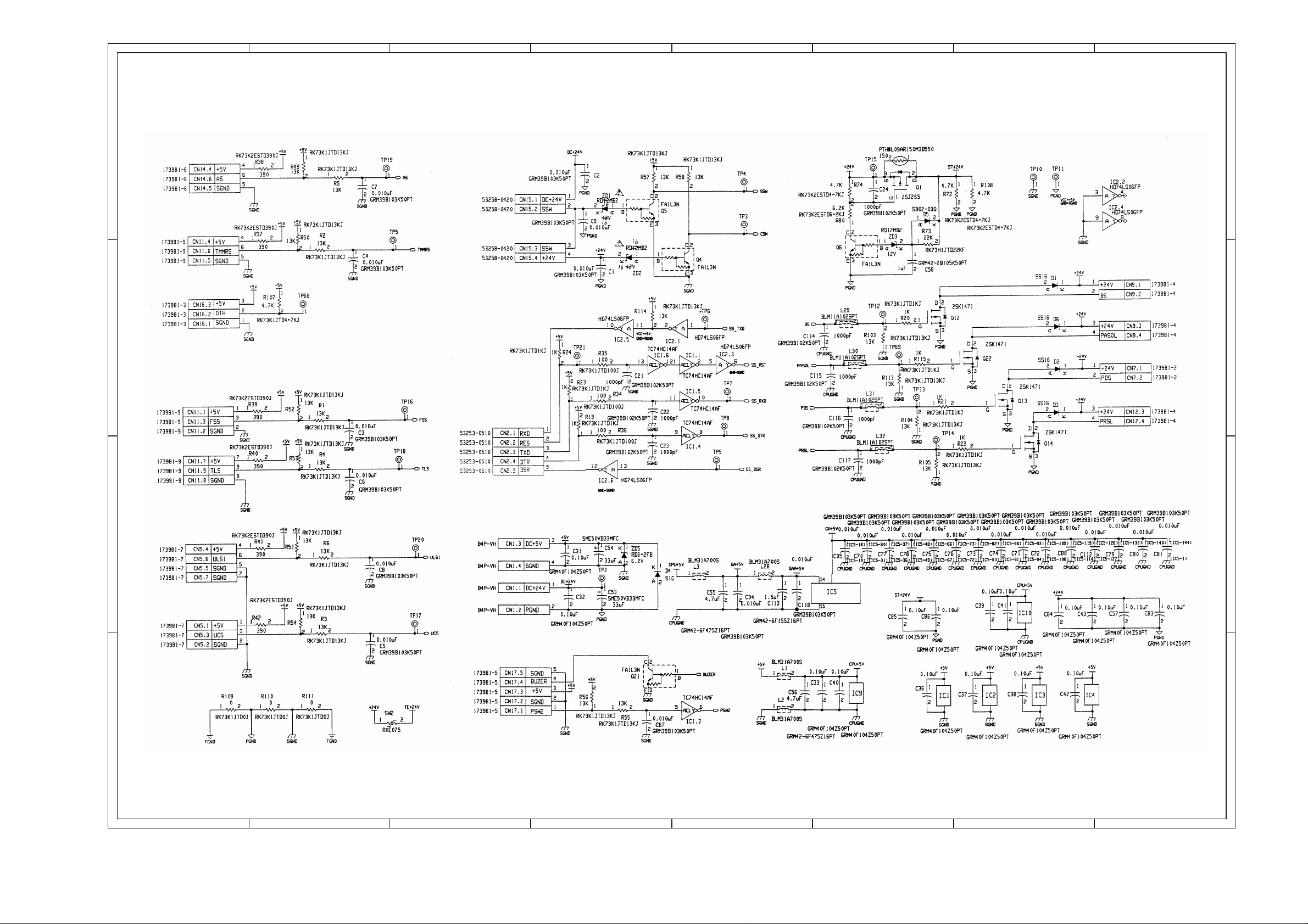
[12] ELECTRICAL SECTION
1. Circuit diagram
Paper reverse sensor
1/2
D
Bin shift motor
Bin shift motor
Paper transport sensor
C
Paper reverse motor
Paper alignment
home position sensor
Unit lock sensor 2
Paper surface sensor
B
Stapler home position sensor
Stapler presence sensor
Staple near end sensor
Paper alignment motor
B
Staple motor
A
A
12345678
12 – 1 12 – 2
Page 2
12345678
2/2
D
Accumulation tray sensor
Tray rotation sensor
Test connector
Set switch
Cover switch
Boomerang solenoid
Paper alignment solenoid
C
Paddle solenoid
Full stack sensor
tray limit sensor
Reverse solenoid
D
C
B
Unit lick 1 sensor
Upper cover sensor
A
B
A
12345678
12 – 3 12 – 4
Page 3

2. Practical wiring diagram
12345678
Process tray paper exit sensor
D
Boomerang rotation sensor
Transport entry port sensor
Unit lock sensor 2 (Front)
Paper reverse sensor (LED)
Paper reverse sensor
Upper cover sensor
C
Unitb lock sensor 1 (Rear)
Bundle exit sensor
Paper alignment plate
home position sensor
Boomerang solenoid
Paddle solenoid
KH56LM2B006
Paper transport motor
TKP54FP8-719
Paper alignment motor
TKP54FP8-718
Paper reverse
D
C
Full stack sensor
Tray rotation sensor
Tray limit sensor
B
Paper surface sensor
Accumulation tray sensor
(Accumulation tray paper
presence)
Power interface
A
Socket Contact
Bin shift motor
B73600-0301
Reverse solenoid
Set switch (Transport path switch)
Cover switch
(Stapler front cover switch)
NU2016
Stapler
B
A
12 – 5 12 – 6
12345678
Page 4

CONTROL PWB SIGNAL ARRANFGEMENT (PARTS SURFACE)
+24V
SBHPS
SGND
+5V
BES
+24V
PDS
DTM_B
DTM_*A
+24V
DTM_*B
+24V
PASOL
BS
+24V
CN5-1 +5V
CN5-2
SGND
UCS
CN5-3
CN5-4
+5V
SGND
CN5-5
CN5-6
ULS1
CN5-7
SGND
CN4-4
PRS
CN4-3
+5V
PRL
CN4-2
+5V
CN4-1
CN3-1 +5V
CN3-2
SGND
JTES
CN3-3
CN3-4
+5V
SGND
CN3-5
CN3-6
BRS
CN3-7
+5V
SGND
CN3-8
CN3-9
PIS
+5V
CN3-10
CN3-11
SGND
CN3-12
ULS2
CN17-1
PSW2
CN17-2
SGND
+5V
CN17-3
BUZER
CN17-4
CN17-5
SGND
CN2-5
DSR
CN2-4
DTR
TXD
CN2-3
RES
CN2-2
CN2-1 RXD
CN6-6
CN6-5
CN6-4
CN6-3
CN6-2 SGND
CN6-1 +5V
CN7-2
CN7-1
CN8-5
CN8-6 DTM_A
CN8-4
CN8-2
CN8-3
CN8-1
CN9-4
CN9-3
CN9-1
CN9-2
CN10-13
CN10-12
CN10-11
CN10-10
CN10-9
CN10-8
CN10-7
CN10-6
CN10-5
CN10-4
CN10-3
CN10-2
CN10-1
CN11-9 TLS
CN11-8
CN11-7
CN11-6
CN11-5
CN11-4
CN11-3
CN11-2
CN11-1
PGND
DRM_*B
DRM_B
DRM_*A
DRM_A
+24V
+24V
DSM_*B
DSM_B
DSM_*A
DSM_A
+24V
+24V
SGND
+5V
TMMRS
SGND
+5V
FSS
SGND
+5V
CN1-4
CN1-3
CN1-2
CN1-1
SGND
+5V
PGND
+24V
SSW
DC+24V
CN15-1
CN15-2
SSW
+24V
CN15-4
CN15-3
+5V
SGND
CN14-1
CN14-2
PLS
+5V
CN14-3
CN14-4
SGND
AS
CN14-6
CN14-5
12 – 7
STP
+5V
CN13-1
CN13-2
SHPS
SGND
CN13-3
CN13-4
STPM0
STPM1
CN13-5
CN13-6
NHES
CN13-7
SGND
OTH
CN16-1
CN16-2
+5V
CN16-3
TMM0
TMM1
CN12-1
CN12-2
+24V
PRSL
CN12-4
CN12-3
Page 5

CONTROL PWB SIGNAL ARRANFGEMENT (SOLDER SURFACE)
12 – 8
Page 6

q
COPYRIGHT C 1998 BY SHARP CORPORATION
All rights reserved.
Printed in Japan.
No part of this publication may be reproduced,
stored in a retrieval system, or transmitted,
in any form or by any means,
electronic, mechanical, photocopying, recording, or otherwise,
without prior written permission of the publisher.
SHARP CORPORATION
Printing & Reprographic Systems
Group
Quality & Reliability Control Center
Yamatokoriyama, Nara 639-1186, Japan
1998 July Printed in Japan S
 Loading...