

Page 1

[11] CIRCUIT DESCRIPTIONS
1. Outline
This circuit controls document transport, reverse, alignment, stapling and discharge.
It is composed of a circuit which controls sensors, switches,and copier signals input, and a circuit which drives the motors and the solenoids, and
CPU, G/C and it peripheral circuits
2. Block diagram
Paper transport
Communication
circuit
Paper reverse
sensor input
circuit
Transport path
entry sensor input
circuit
Address bus
motor drive
circuit
Paper alignment
motor drive
circuit
Paper reverse
motor drive
circuit
Process tray paper
exit sensor input
circuit
Bundle exit sensor
inpout circuit
Accumulation tray
sensor input
circuit
Boomerang
rotation sensor
input circuit
Unit lock sensor 1
input circuit
Unit lock sensor 2
input circuit
Upper cover
sensor input
circuit
Paper alignment
home position
sensor input circuit
Paper level
sensor input
circuit
Data bus
DIP switch push
switch
rush current
limit circuit
+24V
Open/close
switch input
circuit
Power ON
reset circuit
Oscillation
circuit
11MHz
Bin shift motor
drive circuit
Boomerang solenoid
drive circuit
Reverse solenoid
drive circuit
Paddle solenoid
drive circuit
Staple motor
drive circuit
Current limit
circuit
Stapler home
position sensor
input circuit
Staple near end
sensor input circuit
Staple presence
sensor input circuit
Tray rotation
sensor input
ircuit
Tray limit sensor
input circuit
Full stack sensor
input circuit
Power circuit
11 – 1
Page 2
3. Operations
A. Sensor input circuit
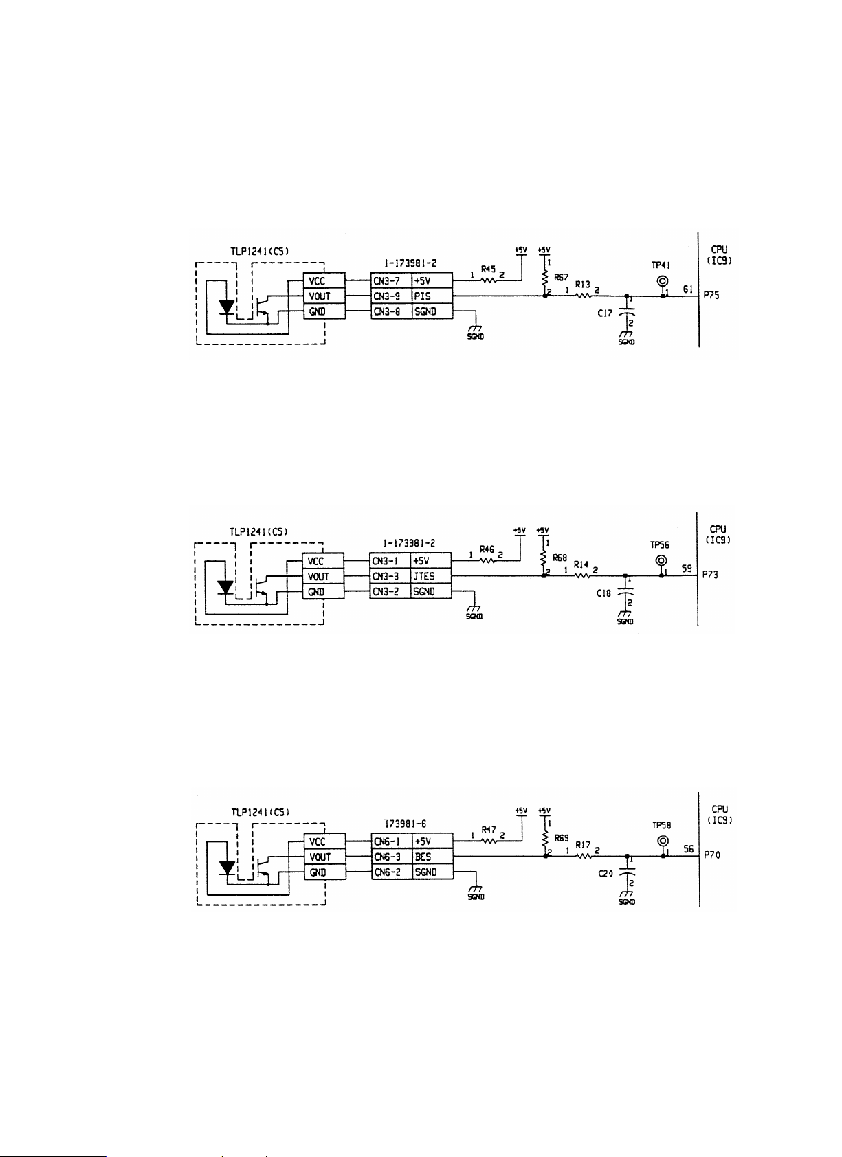
[a] Transport path entry sensor (PIS)
PIS is a photo interrupter which integrates a light emitting diode and photo transistor. A document from the copier is detected by the lever-system
actuator. The light path is interrupted when document presence.
The signal is passed to the CPU (IC9-61 pin) through the noise filter of R13 and C17.
Logic of the signal inputted to the CPU: Document presence
R45 is the current limiting resistor of LED. R67 is the sensor load resistor.
Transport entry port
sensor
(PIS)
[b] Treatment tray exit sensor (JTES)
JTES is the sensor same as the transport entry port sensor (PIS). The document discharged to the treatment tray is detected by the lever-system
actuator. The light path is interrupted when document presence.
The signal is passed to the CPU (IC9-59 pin) through the noise filter of R14 and C18.
Logic of the signal inputted to the CPU: Document presence
R46 is the current limiting resistor of LED. R68 is the sensor load resistor.
® H, Document empty ® L
Transport entry port sensor input circuit
® H, Document empty ® L
Process tray paper
exit sensor
(JTES)
Process tray paper exit sensor input circuit
[c] Bundle exit sensor (BES)
BES is the sensor same as the transport entry port sensor (PIS).
The document on the treatment tray is detected by the lever-system actuator. The light path is interrupted when document is present.
The signal is passed to the CPU (IC9-56 pin) through the noise filter of R17 and C20.
Logic of the signal inputted to the CPU: Document present
R47 is the current limiting resistor of LED. R69 is the sensor load resistor.
Bundle exit sensor
(BES)
® H, Document empty ® L
Bundle exit sensor input circuit
11 – 2
Page 3

[d] Full stack sensor (FSS)
FSS is the sensor same as the transport entry port sensor (PIS).
The document full state on the treatment tray is detected by the douser liked with the tray movement. The light path is interrupted when document
full.
The signal is passed to the G/A (IC5-39 pin) through the noise filter of R1 and C3.
Logic of the signal inputted to the G/A: Document tray full detected
R39 is the current limiting resistor of LED. R52 is the sensor load resistor.
Full stack sensor
(FSS)
® H, Document tray full not detected ® L
Full stack sensor input circuit
[e] Tray limit sensor (TLS)
TLS is the sensor same as the transport entry port sensor (PIS).
The tray bottom (limit) is detected by the douser liked with the tray movement. The light path is interrupted when "Limit." The signal is passed to the
G/A (IC5-41 pin) through the noise filter of R4 and C6.
Logic of the signal inputted to the G/A: Limit detected
R40 is the current limiting resistor of LED. R53 is the sensor load resistor.
® H, Limit not detected ® L
Tray Limit sensor
(TLS)
Limit sensor input circuit
[f] Paper level sensor (PLS)
PLS is the sensor same as the transport entry port sensor (PIS).
The paper level on the tray is detected by the lever-system actuator. The light path is interrupted when "Paper level detected." The signal is passed
to the CPU (IC9-75 pin) through the noise filter of R10 and C15.
Logic of the signal inputted to the CPU: Paper level detected
R44 is the current limiting resistor of LED. R66 is the sensor load resistor.
Paper surface sensor
(PLS)
® H, Paper level not detected ® L
paper surface sensor input circuit
11 – 3
Page 4
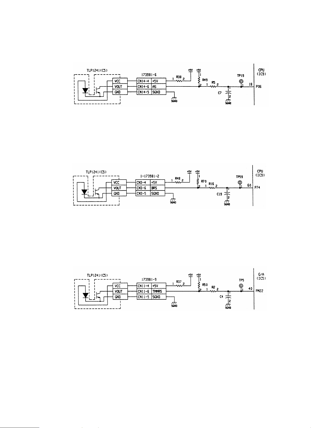
[g] Accumulation tray sensor (AS)
AS is the sensor same as the transport entry port sensor (PIS).
The document presence on the tray is detected by the lever-system actuator. The light path is interrupted when paper presence.
The signal is passed to the CPU (IC9-18 pin) through the noise filter of R5 and C7.
Logic of the signal inputted to the CPU: Paper presence
R38 is the current limiting resistor of LED. R49 is the sensor load resistor.
Accumulation tray
sensor
(AS)
® H, Paper empty ® L
Accumulation tray sensor input circuit
[h] Boomerang rotation sensor (BRS)
BRS is the sensor same as the transport entry port sensor (PIS).
The boomerang rotation and home position are detected by the slit plate. The light path is interrupted when in the home position.
The signal is passed to the CPU (IC9-60 pin) through the noise filter of R16 and C19.
Logic of the signal inputted to the CPU: Home position
R48 is the current limiting resistor of LED. R70 is the sensor load resistor.
® H, Rotating ® L
Boomerang rotation
sensor
(BRS)
Boomerang rotation sensor input circuit
[i] Tray rotation sensor (TMMRS)
TMMRS is the sensor same as the transport entry port sensor (PIS).
The rotation of the motor which lifts up and down the tray is detected. Since the encoder is used as the slit plate, pulses are detected during
rotation.
The signal is passed to the G/A (IC5-40 pin) through the noise filter of R2 and C4.
Logic of the signal inputted to the G/A: Light path interrupted
R37 is the current limiting resistor of LED. R50 is the sensor load resistor.
Tray rotation sensor
(TMMRS)
® H, Light path not interrupted ® L
Tray rotation sensor input circuit
11 – 4
Page 5

[j] Unit lock sensor 1 (ULS1)
ULS1 is the sensor same as the transport entry port sensor (PIS).
The rear side connection with the copier is detected.
The light path is interrupted when connected.
The signal is passed to the CPU (IC9-58 pin) through the noise filter of R6 and C8.
Logic of the signal inputted to the CPU: Not connected
R41 is the current limiting resistor of LED. R51 is the sensor load resistor.
® H, Connected ® L
Unit lock sensor 1
(ULS1)
Unit lock sensor 1 input circuit
[k] Unit lock sensor 2 (ULS2)
ULS2 is the sensor same as the transport entry port sensor (PIS).
The front side connection with the copier is detected.
The light path is interrupted when connected.
The signal is passed to the CPU (IC9-73 pin) through the noise filter of R30 and C29.
Logic of the signal inputted to the CPU: Not connected
R106 is the current limiting resistor of LED. R29 is the sensor load resistor.
® H, Connected ® L
Unit lock sensor 2
(ULS2)
Unit lock sensor 2 input circuit
[l] Upper cover sensor (UCS)
UCS is the sensor same as the transport entry port sensor (PIS).
The open/close of the upper cover of the transport path is detected.
The light path is interrupted when cover closed.
The signal is passed to the CPU (IC9-57 pin) through the noise filter of R3 and C5.
Logic of the signal inputted to the CPU: Cover open
R42 is the current limiting resistor of LED. R54 is the sensor load resistor.
Upper cover sensor
(UCS)
® H, Cover closed ® L
Upper cover sensor input circuit
11 – 5
Page 6

[m] Paper alignment plate home position sensor (SBHPS)
SBHPS is the sensor same as the transport entry port sensor (PIS).
The alignment plate home position is detected.
The light path is interrupted when in the home position.
The signal is passed to the CPU (IC9-72 pin) through the noise filter of R9 and C13.
Logic of the signal inputted to the CPU: Home position not detected
R43 is the current limiting resistor of LED. R61 is the sensor load resistor.
® H, Home position detected ® L
Paper alignment plate
home position
sensor
(SBHPS)
Paper alignment plate home position sensor input circuit
SB
[n] Paper reverse sensor (PRS)
PRS is the transmission type sensor where the LED and the photo transistor are separated.
The document presence in the reverse section is detected.
The light path is interrupted when document detected.
The light emitting side is illuminated by the output of the CPU (IC 9-50 pin) through Q9.
IC 9-50 pin logic: Light emitting
R91 is the current limiting resistor of the light emitted diode.
On the other hand, the signal is inputted to the CPU (IC-9-74 pin) through the noise filter of R8 and C12 and the comparator (IC 4-1).
The reference voltage of the comparator is determined by division of the power voltage (+5V) with R85 and R86.
R88 is used to provide hysteresis to the reference voltage.
R60 is the pull-up resistor of the comparator output.
C11 in the signal line is used to absorb noises. R90 is the load resistor of the photo transistor.
Logic of signal inputted to the CPU: Document presence
® H, Not emitting ® L
® H, DOcument empty ® L
PRL
Paper reverse sensor
(PRS)
Paper reverse sensor input circuit
11 – 6
Page 7

[o] Set switch (SSW)
SSW is the micro switch for release a paper jam in the paper transport path.
This switch is connected with +24V. By opening the open/close section, the contact is opened and this switch actuates as a safety switch. It is
connected in series to CSW.
When the switch is ON, +24V is applied to the cathode of ZD1 and the base current is supplied to Q5 to turn on Q5, inputting the open/close signal
to the CPU (IC 9-17 pin).
C2 and C9 are used to absorb noises. R57 is the pull-up resistor. Logic of signals inputted to the CPU: Cover open
® H, Cover close ® L
[p] Cover switch (CSW)
CSW is the switch of the cover which is opened and closed when replacing staplers.
This switch is connected with –24V. When the open/close section is opened, the contact is opened and this switch actuates as a safety switch. It is
connected in series to SSW.
When the switch is ON, +24V is applied to the cathode of ZD2 and the base current is supplied to Q4 to turn on Q4, inputting the open/close signal
to the CPU (IC 9-16 pin).
C1 is used to absorb noises. R58 is the pull-up resistor.
Logic of signals inputted to the CPU: Cover open
Set switch
(SSW)
® H, Cover close ® L
Set switch input circuit
Cover switch
(CSW)
Cover switch input circuit
11 – 7
Page 8

[q] Stapler home position sensor (SHPS)
SHPS is the micro switch used to detect the staple stand-by position. It is ON when in the home position.
The signal is inputted to the CPU (IC 9-76 pin) through the noise filter of R12 and C16 and the schmidt trigger (IC 1-2).
Logic of signals inputted to the CPU: Home position not detected
Staple home position
sensor
(SHPS)
® H, Home position detected ® L
Staple home position sensor input circuit
[r] Staple near end sensor (NNES)
NNES is the reflection-type sensor which detects staple near end. It integrates the LED and the photo transistor.
No reflection at near end.
The signal is inputted to CPU (IC 9-63 pin) through the noise filter of R18 and C52. DA1 is the protection diode which protects the +5V line voltage
from deflection.
Since this signal is analog, staple empty is detected by the threshold value of 2.75V.
Logic of the signal inputted to the CPU: Staple presence
® 2.75V or less, Staple empty ® 2.75V or above
Staple near end sensor
(NNES)
Stapler near end sensor input circuit
[s] Stapler presence sensor (STP)
STP is used to detect the connection of the stapler unit.
When the connecter is connected, the signal is connected to GND and detected.
The signal is inputted to CPU (IC 9-19 pin) through the noise filter of R7 and C10. R59 is the pull-up resistor.
Stapler presence sensor
(STP)
Stapler presence sensor input circuit
11 – 8
Page 9
B. Solenoid drive circuit
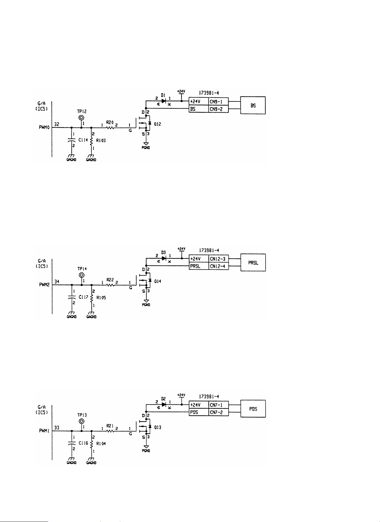
[a] Boomerang solenoid (BS)
BS is the open-frame type solenoid.
By the operation of this solenoid, the large gear is rotated in linkage with the transport motor. In addition, the boomerang in the paper exit section is
rotated in linkage with the large gear. The drive signal from G/A (IC 5-32 pin) is inputted to the gate of FET (Q12).
D1 is used to absorb surging when turning off the solenoid.
R20 is for protection of G/A, and C114 is for absorbing noises. R113 is the pull-down resistor.
Boomerang solenoid
(BS)
Boomerang solenoid input circuit
[b] Reverse solenoid (PRSL)
PRSL is the open-frame type solenoid.
By the operation of this solenoid, the flapper is switched to change the document transport path.
Solenoid ON: Not reversed, Solenoid OFF: reversed
The drive signal from G/A (IC 5-34 pin) is inputted to the gate of FET (Q14).
The drive signal (ON at H) controls PWM, and the ON duty is variable in the range of 0
D3 is for absorbing serge when the solenoid is OFF.
D1 is used to absorb surging when the solenoid is turned off.
R22 is for protection of G/A. C117 is for absorbing noises. R105 is the pull-down resistor.
~ 100% (255 steps).
Reveerse solenoid
(PRSL)
Reverse solenoid drive circuit
[c] Paddle solenoid (PDS)
PDS is the flapper-type solenoid.
By the operation of this solenoid, paddle is rotated in linkage with the transport motor.
The drive signal from G/A (IC 5-33 pin) is inputted to the gate of FET (Q13).
The drive signal (ON at H) controls PWM, and the ON DUTY is variable in the range of 0
D3 is for absorbing serge when the solenoid is OFF.
D2 is used to absorb surging when the solenoid is turned off. R21 is for protection of G/A. C116 is for absorbing noises. R104 is the pull-down
resistor.
~ 100% (255 steps).
Paddle solenoid
(PDS)
Paddle solenoid drive circuit
11 – 9
Page 10

C. Motor drive circuit
[a] Document transport m o tor (D TM )
This circuit controls rotation, stop, and rotating direction of DTM and the motor current. It is composed of the G/A (IC5), the constant-current
chopper system driver IC (IC11), etc.
The G/A (IC5-78
The PWM signal outputted from the G/A (IC 5-51 pin) is divided and integrated with R89, R15, and C62 to be converted into a constant voltage. The
converted voltage is inputted to IC11-9 pin and 11 pin to set the motor current value. The motor current value is controlled arbitrarily by varying the
ON DUTY of the PWM signal.
C89- 92 and C101 are for absorbing noises. C59 and C62 are for reducing sounds when the motor is held. C50 and C69 are for stabilizing the +5V
power. C66 is for stabilizing the ST +24V power.
~ 81 pin) outputs the stepping motor drive excitement pattern signal to control the motor rotating speed and the rotating direction.
paper transport motor
(DTM)
Paper transport motor drive circuit
[b] Document alignm en t m oto r (DSM )
This circuit controls rotation, stop, and rotating direction of DSM and the motor current. It is composed of the G/A (IC5), the constant-current
chopper system driver IC (IC7), etc.
The G/A (IC5-25
The PWM signal outputted from the G/A (IC 5-35 pin) is divided and integrated with R93, R94 and C64 to be converted into a constant voltage. The
converted voltage is inputted to IC7-9 pin and 11 pin to set the motor current value. The motor current value is controlled arbitrarily by varying the
ON DUTY of the PWM signal.
C93- 96 and C103 are for absorbing noises. C61 and C64 are for reducing sounds when the motor is held. C47 and C68 are for stabilizing the +5V
power. C65 is for stabilizing the ST +24V power.
~ 28 pin) outputs the stepping motor drive excitement pattern signal to control the motor rotating speed and the rotating direction.
Document alignment
motor (DSM)
Document alignment motor
11 – 10
Page 11

[c] Document reverse motor (DRM)
This circuit controls rotation, stop, and rotating direction of DRM and the motor current. It is composed of the G/A (IC5), the constant-current
chopper system driver IC (IC6), etc.
The G/A (IC5-57
The PWM signal outputted from the G/A (IC 5-50 pin) is divided and integrated with R92, R87, and C63 to be converted into a constant voltage. The
converted voltage is inputted to IC6-9 pin and 11 pin to set the motor current value. The motor current value is controlled arbitrarily by varying the
ON DUTY of the PWM signal.
C97-100 and C102 are for absorbing noises. C60 and C63 are for reducing sounds when the motor is held. C45 and C67 are for stabilizing the +5V
power. C65 of DSM is commonly used for stabilizing the ST +24V power.
~ 60 pin) outputs the stepping motor drive excitement pattern signal to control the motor rotating speed and the rotating direction.
Paper reverse motor
(DRM)
Paper reverse motor drive circuit
[d] Bin shift moto r (T M M )
This circuit controls rotation, stop, and rotating direction of DTM and the motor current. It is composed of the G/A (IC5), the bridge circuit composed
of the FET (Q15
The motor rotation, stop, and rotating direction are controlled by the combinations of binary logic inputted from the CPU (IC9) to the G/A (IC5)
through the data bus. By this control, the control signal is outputted to the G/A (IC5-74
These signals are inputted to the bridge circuit.
C25, C26, and C104
Q7 and Q8 are used to turn on Q17 and Q18 respectively.
R75, R76, R81, and R82 are the dividing resistances used to obtain VGS of the FET.
In addition, the following hard limit is provided for the rotating direction of TMM.
CW direction (Bin UP): Document level sensor (PLS)
CCW direction (Bin DOWN): Tray limit sensor (TLS)
~ 18), etc.
~ 77 pin).
~ C107 are for absorbing noises.
Bin shift motor
(TMM)
Bin shift motor drive circuit
11 – 11
Page 12

[e] Stapler (SU)
The stapler unit includes the staple motor (STPM), the stapler home position sensor (SHPS), and the staple near end sensor (NNSE).
For SHPS and NNES, refer to A-[q] and [r].
STPM controls the rotation, stop and rotating direction. It is composed of the G/A (IC5) and the bridge circuit composed of the FET (Q2, Q3, Q19,
and Q20).
The motor rotation, stop, and rotating direction are controlled by the combinations of binary logic inputted from the CPU (IC9) to the G/A (IC5)
through the data bus. By this control, the control signal is outputted to the G/A (IC5-20
These signals are inputted to the bridge circuit.
C27, C28, and C108
Q10 and Q11 are used to turn on Q2 and Q3 respectively.
R78, R79, R81, R83, R84 are the dividing resistances used to obtain VGS of the FET.
~ C111 are for absorbing noises.
~ 23 pin).
Staple motor
(STPM)
Staple motor drive circuit
D. Other circuits
[a] Reset circuit
This circuit generates the rest signal of the CPU and the G/A. It is composed of IC8 and its peripheral circuits.
IC8 is provided with the power on reset function when supplying the power and the reset function in case of abnormal decrease of +5V. The reset
state is held until a certain time passes from the time when the power line reached about 4.3V after supplying the power. The reset holding time is
set with the capacity of C82.
This circuit is provided also with the watchdog timer function. The watchdog timer is built in the G/A (IC5), and it starts operation when the RESET
pin becomes HIGH. This monitors hung up or other abnormality of the CPU.
The monitoring method is: The initial value (data) is written from the CPU to the G/A. This data is counted down inside the G/A. Normally the data is
rewritten before returning to the initial value. In case of hung up of the CPU, however, the data is not returned to the initial value and the counter
becomes zero.
At that time, the G/A resets the CPU and retries until the CPU gets started again.
C48, C49, and C51 are for absorbing noises.
Reset circuit
11 – 12
Page 13

[b] Rush current limit circuit
This circuit limits a rush current which flows into the current regeneration capacitors (C65, C66) which are provided in the document transport motor
(DTM), document reverse motor (DRM), and the document alignment motor (DSM). It is composed of the posistor (PTH1) for limiting the current
and the FET (Q1) fort flowing the current in the normal state.
During the time from when the set switch (SSW) or the cover switch (CSW) is closed to when the ZD3 cathode voltage reaches 12V, the base
current of Q6 is not supplied and it is kept at OFF. Therefore, Q1 is OFF and a current flows through PTH1.
On the other hand, when the ZD3 cathode voltage exceeds 12V, the base current flows through Q6 to turn it on. Therefore Q1 is turned on and the
current flowing through PTH1 flows through Q1, canceling the current limit operation.
R72 and R108 are the discharge resistances for discharging charges accumulated in C65 and C66 when SSW or CSW is opened.
R73 and C58 form the integration circuit which sets the timing of flowing a current through PTH1 when SSW or CSW is closed. D5 is the shot key
diode which discharges the charges of C58. C24 is for absorbing noises. R74 and R80 are the dividing resistors to obtain VGS used to turn on Q1.
+24V
(Power supplied from the main body)
Rush current limit circuit
[c] Current lim it circu it
This circuit is used to limit the starting current of the staple motor at a certain level. It is composed of the resistor for detection of the current value
and the voltage comparator.
The negative voltage side of the motor is connected with the pickup resistance of R99 and R100, and the current flowing through the drive circuit is
converted into a voltage value by this pickup resistor.
The converted voltage value is compared with the reference voltage by the comparator (IC3-1).
The reference voltage is obtained by dividing the zenor voltage generated by R77 and ZD4 with R97 and R98.
When the voltage exceeds this reference level, the output pin 1 of IC3-1 becomes LOW, and the voltage is inputted to the G/A 101 pin to stop
supplying the +24V power to the motor.
Therefore, the current value is not increased further.
When the converted voltage value falls below the reference level, the +24V power is supplied again to start conduction of the motor.
Since the operating current level of this circuit is considerably high, it operates only when the motor starts, and does not operates in the normal
state.
R11 and C30 are for absorbing the noises. R71 is the pull-up resistance.
Current limit circuit
11 – 13
 Loading...