

SHARP ARFN2 Lift tray section
[1] PRODUCT OUTLINE
6. Weight
This machine allows separate paper exit to different trays, and stapling of sorted copied sheets. The first-step tray holds 250 sheets,
and the second-step tray holds 750 sheets.
[2] SPECIFICATIONS
1. Type
Installation to copier body (Separate installation allowed)
2. Tray section specifications
Upper tray Lower tray
Tray type Normal tray Lift tray
Capacity 250 sheets (A4/Letter,
Storing system Face up Face up/Face
Paper exit size A3
Paper weight 52
Paper full detection None Yes
2
)
80g/m
~ A6R
´ 17" ~
11"
´ 8 1/2", 12" ´ 18"
5 1/2"
~ 128g/m
200g/m
above, A4/Letter size or
smaller)
2
, 176g/m2,
2
(For 105g/m2 or
750 sheets
(A4/Letter, 80g/m2)
down
A4, B5
´ 11"
8 1/2"
~ 128g/m
56
2
22Kg
7. Power
Supplied from the copier body.
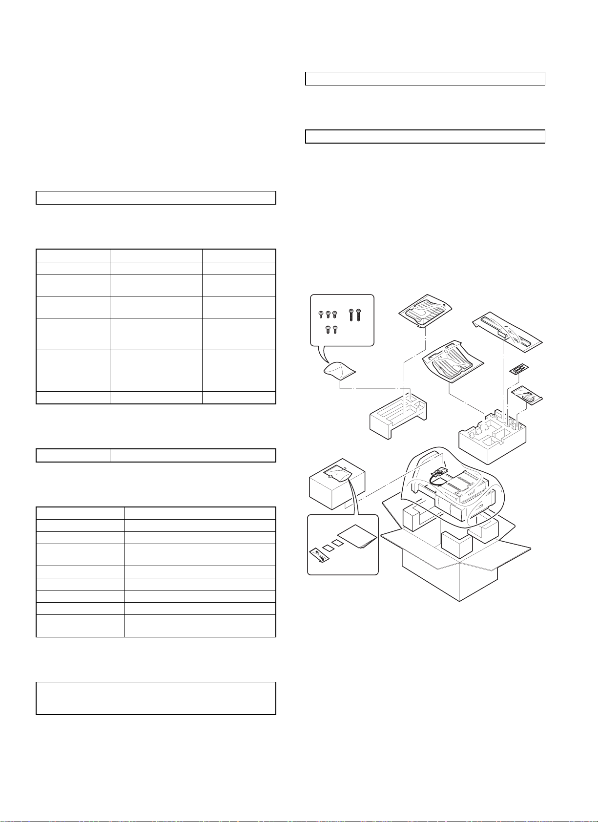
[3] UNPACKING AND
INSTALLATION
1. Unpacking
For unpacking, refer to the figure below.
3. Lift tray section
Offset amount 15mm, A4 35mm: B5 24mm: 8.5 ´ 11
4. Staple section
Storing system Face up
Stapling system Flat clinch
Stapling capacity 30 sheets (80g/m
Applicable size AB series: A4, B5
Inch series: 8 1/2
Alignment Max. shift width: 1mm
Stapling reference One position (front)
Staple supply system Cartridge system (5000 pcs.)
Staple Common with AR-SS1, SF-S54
Detection Detection of no staple/no cartridge/no
stapler
2
)
´ 11
5. External dimensions
457mm (W) ´ 518mm (D) ´ 820mm (H)
552mm (W)
extended)
´ 518mm (D) ´ 866mm (H)(with the upper tray
1 – 1
2. Installation
Before installation, check that the following parts are included in the
package.
Parts included
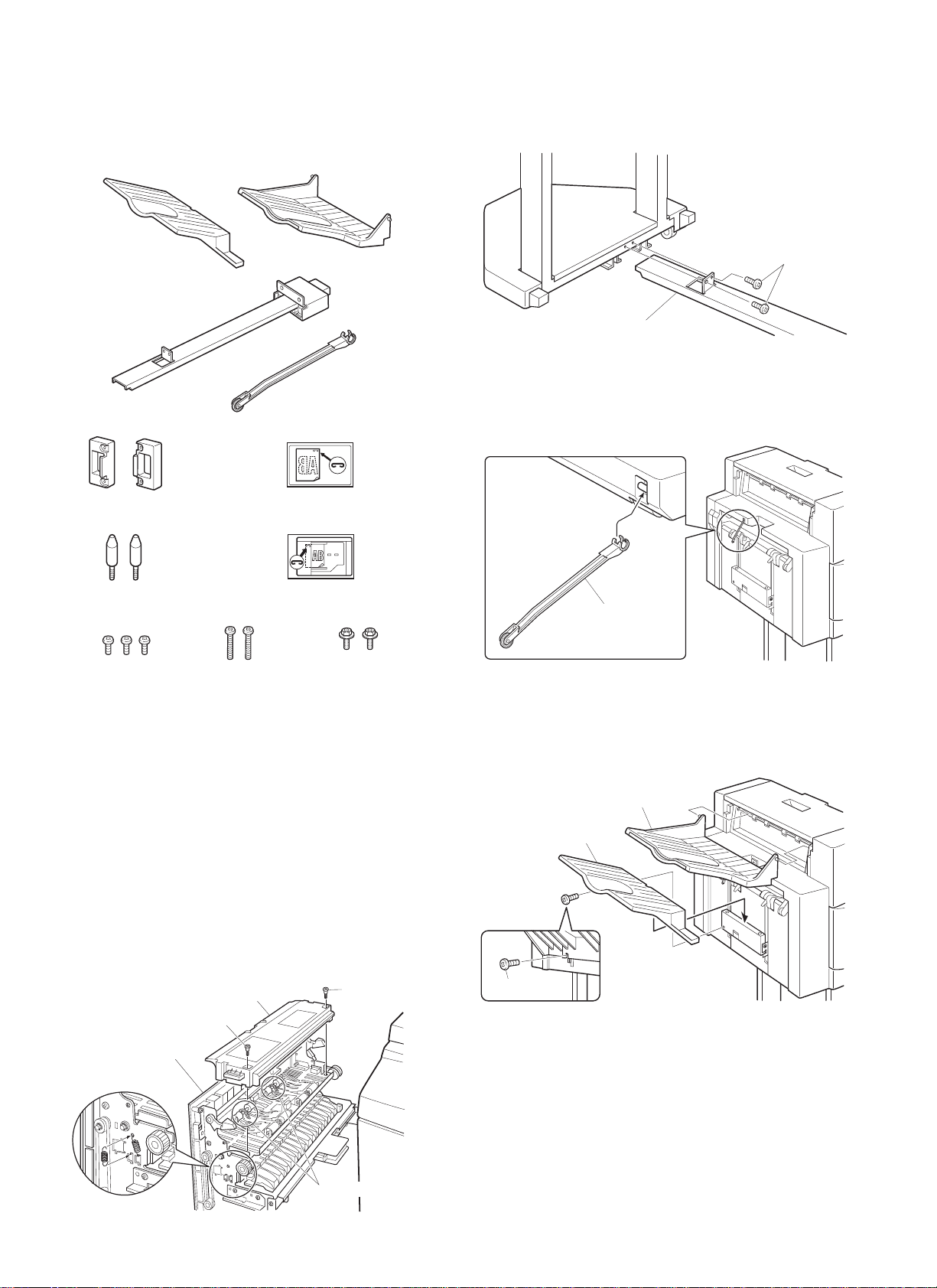
1. Attach the connecting plate to the finisher.
Insert the connecting plate into the lower part of the finisher and
secure it using two screws A.
Tray 2: 1
Connecting plate: 1
Lock plates: 2
Positioning screws: 2
Screws A: 3
Screws B: 2
Exit tray: 1
Paper holder lever: 1
Stapling position label A: 1
Stapling position label B: 1
Screws C: 2
Unplug the copier’s power cord before carrying out
the following procedure.
Carry out the following steps before installing the
AR-FN2.
1. Pull out the exit unit of the copier until it stops.
2. Remove the two exit area cover fixing screws and remove the exit
area cover.
3. Remove the two transport springs that are attached to the exit
paper guide.
4. Store the two removed transport springs by hanging on the exit
unit front frame (position in Fig. 1).
5. Reattach the exit area cover to its original position and secure it
using two fixing screws.
6. Insert the exit unit into the copier.
Exit unit
Exit area cover
Fixing screw
Fixing screw
Screws A
Connecting plate
2. Attach the paper holder lever.
Attach the paper holder lever by inserting it into the mounting location
of the finisher as shown in the figure.
Paper holder lever
3. Attach the exit tray and tray 2.
Insert tray 2 securely into the tray mounting stand and secure it using
one screw A. Then attach the exit tray to the finisher by inserting boss
at (1) first.
Screw A
Exit tray
Tray 2
(2)
(1)
[Fig. 1]
Transport spring
1 – 2
 Loading...