

Page 1
[10] TROUBLESHOOTING
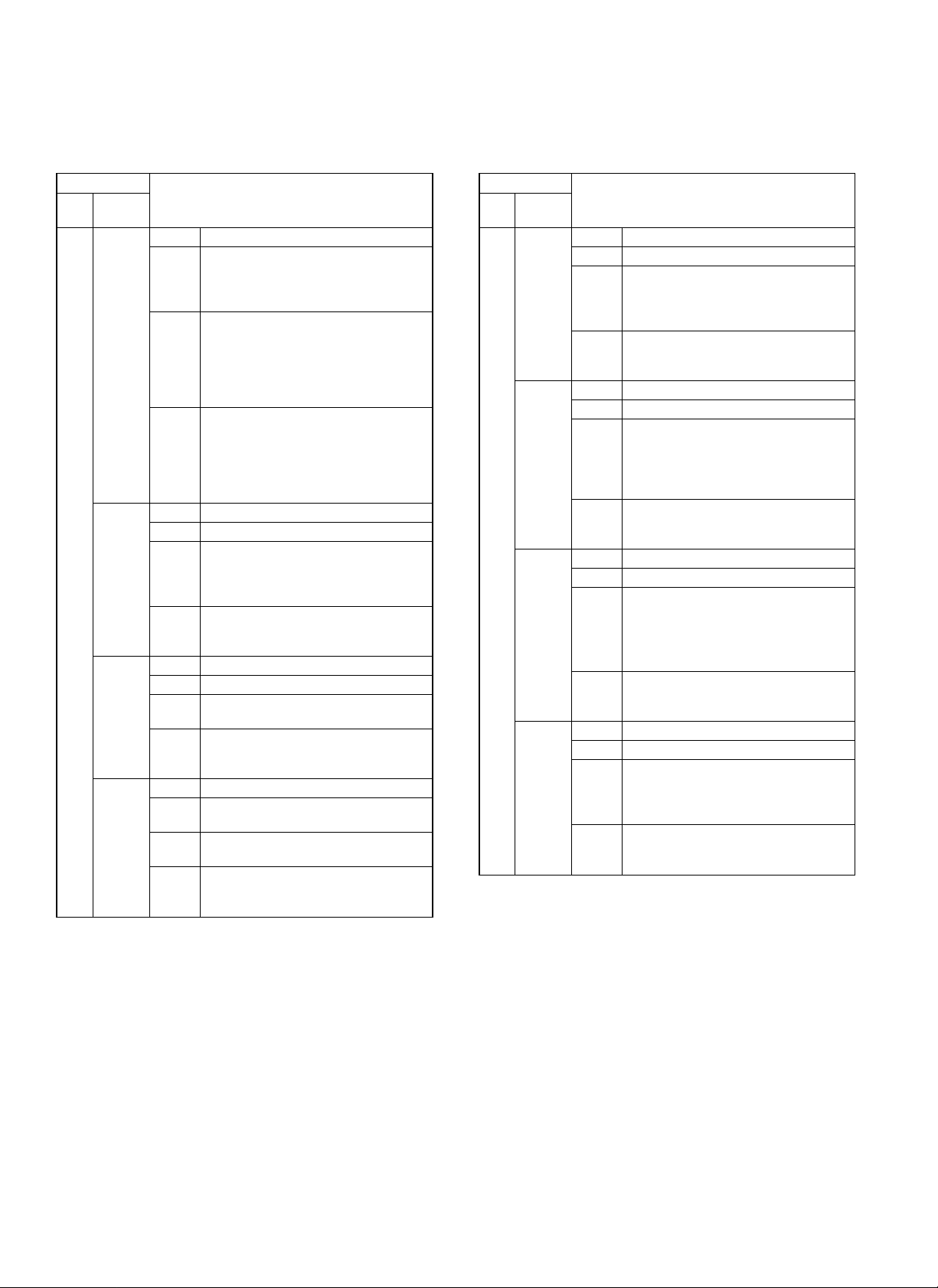
1. T rouble code
Trouble code
Main
code
Sub
code
F1 00 Content Finisher communication trouble
Detail Communication line test error occurs
when power is turned on or after the exit
of a simulation mode.
Improper communication with sorter
Cause Improper connection or broken wire of
Check
and
remedy
01 Content Finisher 2 alignment section trouble
Detail Alignment plate shift trouble
Cause Motor lock
Check
and
remedy
04 Content Finisher elevater lower limit detected
Detail Elevater has exceeded lower limit.
Cause Sensor defective
Check
and
remedy
05 Content Stack tray sensor abnormality
Detail Stack tray sensor turns on in abnormal
Cause Sensor defective
Check
and
remedy
connector or harness between copier
and Finisher
Finisher control PWB defective
Control PWB (PCU) defective
Malfunction due to noise
Clear by turning the power supply
OFF/ON.
Check communication line connector and
harness.
Replace Finisher control PWB or PCU
PWB.
Motor rpm abnormality
Motor overcurrent
Finisher control PWB trouble
Check the jogger motor operation with
SIM 3-3.
Finisher control PWB defective
Check sensor with SIM3-2.
combination.
Finisher control PWB defective
Check sensor with SIM3-2.
Description
Trouble code
Main
code
Sub
code
F1 10 Content Staple unit operation trouble
Detail Staple operation trouble
Cause Motor lock
Check
and
remedy
11 Content Boomerang rotation
Detail Boomerang solenoid
Cause Boomerang solenoid operation trouble
Check
and
remedy
14 Content Stack tray abnormality
Detail Stack tray control sensor abnormality
Cause a) The paper level sensor or the full stack
Check
and
remedy
15 Content Stack tray motor lock
Detail Elevator motor trouble
Cause Motor lock
Check
and
remedy
Motor rpm abnormality
Motor overcurrent
Finisher control PWB trouble
Check the staple motor operation with
SIM 3-3.
Boomerang rotation sensor abnormality
Motor rpm abnormality
Motor overcurrent
Finisher control PWB trouble
Check the with SIM 3-2.
b) When the tray is lifted, the stack tray is
Check the sensors with SIM 3-2.
Check the elevator motor operation with
SIM 3-3.
Motor rpm abnormality
Motor overcurrent
Finisher control PWB trouble
Check the elevator motor operation with
SIM 3-3.
Description
sensor are not turned on in a certain
time after starting the tray.
locked.
10 – 1
Page 2

2. T roubleshooting
Trouble Cause Troubleshooting and treatment
(1) When the main switch of
the copier is turned on,
it does not work at all.
(2) The transport motor
does not operate.
(3) The reverse motor does
not operate.
(4) The alignment motor
does not operate.
(5) The accumulation tray
motor does not operate.
(6) The boomerang
solenoid does not
operate.
(7) The reverse solenoid
does not operate.
(8) The paddle solenoid
does not operate.
(9) The copier display
shows "Finisher paper
jam."
(10) The copier display
shows "Finisher not
connected."
(11) The copier display
shows Finisher cover
open.
(12) Paper is stopped
during exit operation
1. Contact trouble with the copier Check contact of each connector.
2. Contact trouble of the connector
pin of the connection wire with the
copier
3. Stapler section cover switch, lower
transport path set switch trouble
4. Control PWB trouble If DC24V and DC5V are inputted from the copier and LED on the control
1. Motor connector pin contact trouble
Make a conduction test between connectors and replace, if not
conducting.
Make a conduction test between switches, and replace if necessary.
PWB does not blink and 24V is ont supplied to CN8-1, replace the control
PWB.
· Check contact of the connector, and repair if necessary.
· Make a conduction test of connector pins and replace if not conducting.
2. Motor coil disconnection Make a conduction test between coils and replace the motor if ont
conducting.
3. Control PWB trouble If the motor does not operate in the load operation mode, replace the
control PWB.
1. Solenoid connector pin contact
trouble
2. Solenoid coil disconnection Make a conduction test between coils, and replace the solenoid if not
3. Control PWB trouble If the solenoid does not operate in the load operation mode, replace the
1. Paper jam Visually inspect and remove the jam.
2. Transport entry port sensor trouble Measure the voltage at TP41 on the control PWB. If it is not 0V at sensor
3. Treatment tray exit sensor trouble Measure the voltage at TP56 on the control PWB. If it is not 0V at sensor
4. Bundle exit sensor trouble Measure the voltage at TP58 on the control PWB. If it is not 0V at sensor
5. Paper reverse sensor trouble Measure the voltage at TP22 on the control PWB. If it is not 0V at sensor
6. Sensor connector pin contact
trouble
7. Control PWB trouble When each sensor is turned on/off, the sensor level is changed but the
1. Finisher not connected Connect the finisher.
2. Unit lock sensor 1 trouble Measure the voltage at TP20 on the control PWB. If it is not 0V at when
3. Unit lock sensor 2 trouble Measure the voltage at TP46 on the control PWB. If it is not 0V when
6. Sensor connector pin contact
trouble
7. Control PWB trouble When each sensor is turned on/off, the sensor level is changed but the
1. Upper cover open Visually inspect and remove the cover.
2. Upper cover sensor trouble Measure the voltage at TP17 on the control PWB. If it is not 0V at sensor
3. Sensor connector pin contact
trouble
4. Control PWB trouble When each sensor is turned on/off, the sensor level is changed but the
1. Boomerang rotation sensor trouble Measure the voltage at TP59 on the control PWB. If it is not 0V at sensor
2. Paper alignment home position
sensor trouble
3. Sensor connector pin contact
trouble
4. Control PWB trouble When each sensor is turned on/off, the sensor level is changed but the
· Check contact of the connector, and repair if necessary.
· Make a conduction test of connector pins, and replace if not
conducting.
conducting.
control PWB.
OFF and 5V at ON, replace the transport path entry port sensor.
OFF and 5V at ON, replace the treatment tray exit sensor.
OFF and 5V at ON, replace the bundle exit sensor.
OFF and 5V at ON, replace the paper reverse sensor.
Make a conduction test of connector pins, and replace the pin if not
conducting.
phenomenon is not changed, replace the control PWB.
coupling and 5V when not coupling, replace the unit lock sensor 1.
coupling and 5V when not coupling, replace the unit lock sensor 2.
Make a conduction test of connector pins, and replace the pin if not
conducting.
phenomenon is not changed, replace the control PWB.
OFF and 5V at ON, replace the transport path entry port sensor.
Make a conduction test of connector pins, and replace pins if not
conducting.
phenomenon is not changed, replace the control PWB.
OFF and 5V at sensor ON, replace the transport path entry port sensor.
Measure the voltage at TP23 on the control PWB. If it is not 0V at sensor
oFF and 5V at ON, replace the transport path entry sensor.
Make a conduction test of connector pins, and replace the pins if not
conducting.
phenomenon is not changed, replace the control PWB.
10 – 2
Page 3

Trouble Cause Troubleshooting and treatment
(13) The accumulation tray
does not stop at the
proper position.
1. Tray rotation sensor trouble Measure the voltage at TP5 on the control PWB. If it is not 0V at sensor
OFF and 5V at ON, replace the transport path entry sensor.
2. Full stack sensor trouble Measure the voltage at TP16 on the control PWB. If it is not 0V at sensor
OFF and 5V at ON, replace the transport path entry port sensor.
3. Tray limit sensor trouble Measure the voltage at Tp18 on the control PWB. If it is not 0V at sensor
OFF and 5V at ON, replace the transport path entry port sensor.
4. Paper surface sensor trouble Measure the voltage at TP47 on the control PWB. If it is not 0V at sensor
OFF and 5V at ON, replace the transport path entry port sensor.
5. Accumulation tray sensor trouble Measure the voltage at TP19 on the control PWB. If it is not 5V at sensor
OFF and 0V at ON, replace the transport path entry port sensor.
6. Sensor connector pin contact
trouble
Make a conduction test of connector pins, and replace pins if not
conducting.
7. Control PWB trouble When each sensor is turned on/off, the sensor level is changed but the
phenomenon is not changed, replace the control PWB.
10 – 3
 Loading...