

Page 1
CODE: 00ZAR162//A1E
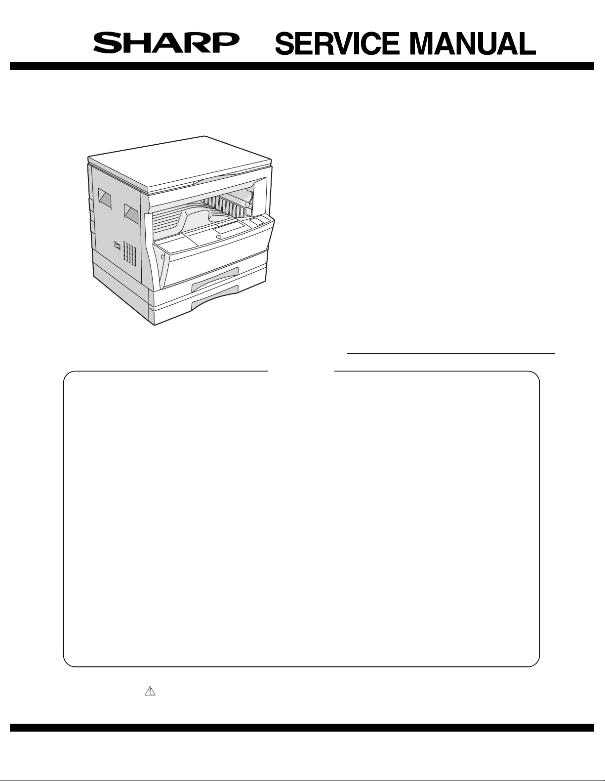
DIGITAL COPIER
AR-162
AR-163
AR-201
AR-206
AR-207
MODEL AR-F201
CONTENTS
[ 1 ] GENERAL . . . . . . . . . . . . . . . . . . . . . . . . . . . . . . . . . . . . . . . . . . . . . . . . 1-1
[ 2 ] SPECIFICATIONS . . . . . . . . . . . . . . . . . . . . . . . . . . . . . . . . . . . . . . . . . . 2-1
[ 3 ] CONSUMABLE PARTS . . . . . . . . . . . . . . . . . . . . . . . . . . . . . . . . . . . . . 3-1
[ 4 ] EXTERNAL VIEWS AND INTERNAL STRUCTURES . . . . . . . . . . . . . .4-1
[ 5 ] UNPACKING AND INSTALLATION . . . . . . . . . . . . . . . . . . . . . . . . . . . . 5-1
[ 6 ] ADJUSTMENTS . . . . . . . . . . . . . . . . . . . . . . . . . . . . . . . . . . . . . . . . . . .6 -1
[ 7 ] SIMULATIONS . . . . . . . . . . . . . . . . . . . . . . . . . . . . . . . . . . . . . . . . . . . . 7-1
[ 8 ] USER PROGRAMS . . . . . . . . . . . . . . . . . . . . . . . . . . . . . . . . . . . . . . . . . 8-1
[ 9 ] TROUBLE CODE LIST . . . . . . . . . . . . . . . . . . . . . . . . . . . . . . . . . . . . . . 9-1
[10] MAINTENANCE . . . . . . . . . . . . . . . . . . . . . . . . . . . . . . . . . . . . . . . . . . .10-1
[11] DISASSEMBLY AND ASSEMBLY . . . . . . . . . . . . . . . . . . . . . . . . . . . . 11-1
[12] FLASH ROM VERSION UP PROCEDURE . . . . . . . . . . . . . . . . . . . . . 12-1
[13] ELECTRICAL SECTION . . . . . . . . . . . . . . . . . . . . . . . . . . . . . . . . . . . .13-1
Parts marked with " " are important for maintaining the safety of the set. Be sure to replace these parts with specified
ones for maintaining the safty and performance of the set.
This document has been published to be used
SHARP CORPORATION
for after sales service only.
The contents are subject to change without notice.
Page 2
CAUTION
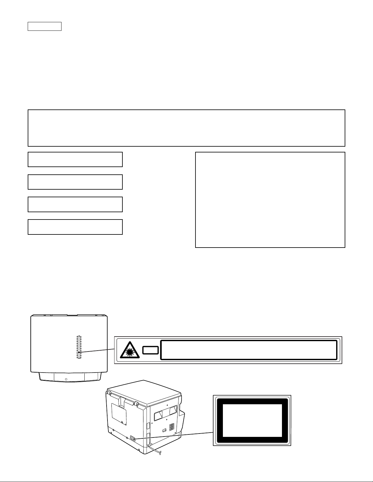
This product is a class 1 laser product that complies with 21CFR 1040.10 and 1040.11 of the CDRH standard and IEC825. This means that this
machine does not produce hazardous laser radiation. The use of controls, adjustments or performance of procedures other than those specified
herein may result in hazardous radiation exposure.
This laser radiation is not a danger to the skin, but when an exact focusing of the laser beam is achieved on the eye’s retina, there is the danger of
spot damage to the retina.
The following cautions must be observed to avoid exposure of the laser beam to your eyes at the time of servicing.
1) When a problem in the laser optical unit has occurred, the whole optical unit must be exchanged as a unit, not as individual parts.
2) Do not look into the machine with the main switch turned on after removing the developer unit, toner cartridge, and drum cartridge.
3) Do not look into the laser beam exposure slit of the laser optical unit with the connector connected when removing and installing the optical
system.
4) The middle frame contains the safety interlock switch.
Do not defeat the safety interlock by inserting wedges or other items into the switch slot.
Warning!
This product is a class A product.
If it is operated in households, offices or similar surroundings, it can produce radio interferences at other
appliances, so that the user has to take adequate countermeasures.
CLASS 1 LASER PRODUCT
LASER KLASSE 1
LUOKAN 1 LASERLAITE
KLASS 1 LASERAPPARAT
CAUTION
INVISIBLE LASER RADIATION,
WHEN OPEN AND INTERLOCKS DEFEATED. AVOID
EXPOSURE TO BEAM.
VORSICHT
UNSICHTBARE LASERSTRAHLUNG,
WENN ABDECKUNG GEÖFFNET UND
SICHERHEITSVERRIEGELUNG ÜBERBRÜCKT. NICHT
DEM STRAHL AUSSETZEN.
LAITTEEN KÄYTTÄMINEN MUULLA KUIN TÄSSÄ
KÄYTTÖOHJEESSA MAINITULLA TAVALLA SAATTAA
ALTISTAA KÄYTTÄJÄN TURVALLISUUSLUOKAN 1
YLITTÄVÄLLE NÄKYMÄTTÖMÄLLE
LASERSÄTEILYLLE.
OM APPARATEN ANVÄNDS PÅ ANNAT SÄTT ÄN I
DENNA BRUKSANVISNING SPECIFICERATS, KAN
ANVÄNDAREN UTSÄTTAS FÖR OSYNLIG
LASERSTRÅLNING, SOM ÖVERSKRIDER GRÄNSEN
FÖR LASERKLASS 1.
VARO !
AVATTAESSA JA SUOJALUKITUS OHITETTAESSA OLET
ALTTIINA NÄKYMÄTTÖMÄLLE LASERSÄTEILYLLE ÄLÄ
KATSO SÄTEESEEN.
ADVARSEL
USYNLIG LASERSTRÅLNING VED ÅBNING, NÅR
SIKKERHEDSBRYDERE ER UDE AF
FUNKTION. UNDGÅ UDSAETTELSE FOR
STRÅLNING.
VAROITUS!
VARNING
VARNING !
OSYNLIG LASERSTRÅLNING NÄR DENNA DEL ÄR
ÖPPNAD OCH SPÄRREN ÄR URKOPPLAD. BETRAKTA EJ
STRÅLEN. – STRÅLEN ÄR FARLIG.
INVISIBLE LASER RADIATION WHEN OPEN AND INTERLOCKS DEFEATED.
CAUTION
AVOID EXPOSURE TO BEAM.
UNSICHTBARE LASERSTRAHLUNG WENN ABDECKUNG GE…FFNET UND
VORSICHT
Laserstrahl
SICHERHEITSVERRIEGELUNG †BERER†CKT. NICHT DEM STRAHL AUSSETZEN.
USYNLIG LASERSTR LING VED BNING, N R SIKKERHEDSAFBRYDERE ER
ADVARSEL
UDE AF FUNKTION. UNDGA UDSAETTELSE FOR STR LING.
Disconnect the AC cord before servicing the unit.
USYNLIG LASERSTR LING N R DEKSEL PNES OG SIKKERHEDSL S BRYTES.
UNNG EKSPONERING FOR STR LEN.
ADVERSEL
OSYNLIG LASERSTR LNING N R DENNA DEL R …PPNAD OCH SP RRAR R
VARNING
URKOPPLADE. STR LEN R FARLIG. BETRAKTA EJ STR LEN.
AVATTAESSA JA SUOJALUKITUS OHITETTAESSA OLET ALTTIINA N KYM T…NT
VARO!
LASERS TEILYLLE. L KATSO S TEESEEN.
CLASS 1
LASER PRODUCT
LASER KLASSE 1
LASER WAVE – LENGTH : 795 ± 15 mm
Pulse times : 0.481 ms/6 mm
Out put power : 5 mW
Page 3

CONTENTS
[ 1 ] GENERAL . . . . . . . . . . . . . . . . . . . . . . . . . . . . . . . 1-1
1. Note for servicing . . . . . . . . . . . . . . . . . . . . . . . 1-1
[ 2 ] SPECIFICATIONS . . . . . . . . . . . . . . . . . . . . . . . . 2-1
1. Copy mode . . . . . . . . . . . . . . . . . . . . . . . . . . . . 2-1
[ 3 ] CONSUMABLE PARTS . . . . . . . . . . . . . . . . . . . 3-1
1. Supply system table . . . . . . . . . . . . . . . . . . . . . 3-1
2. Environment conditions . . . . . . . . . . . . . . . . . . . 3-3
3. Production number identifi cati on . . . . . . . . . . . . 3-3
4. Consumable parts recycli ng procedure . . . . . . 3-4
[ 4 ] EXTERNAL VIEWS AND INTERNAL
STRUCTURES . . . . . . . . . . . . . . . . . . . . . . . . . . . 4-1
1. Appearance . . . . . . . . . . . . . . . . . . . . . . . . . . . . 4-1
2. Internal . . . . . . . . . . . . . . . . . . . . . . . . . . . . . . . 4-1
3. Operation Section . . . . . . . . . . . . . . . . . . . . . . . 4-2
4. Motor, solenoid, clutch . . . . . . . . . . . . . . . . . . . 4-3
5. Sensor, switch . . . . . . . . . . . . . . . . . . . . . . . . . . 4-4
6. PWB unit . . . . . . . . . . . . . . . . . . . . . . . . . . . . . . 4-5
7. Cross sectional view . . . . . . . . . . . . . . . . . . . . . 4-6
[ 5 ] UNPACKING AND INSTALLATION . . . . . . . . . 5-1
1. Installing conditions . . . . . . . . . . . . . . . . . . . . . . 5-1
2. Removal of protective material and
fixing screw . . . . . . . . . . . . . . . . . . . . . . . . . . . . 5-1
3. Installation of developing cart r id ge . . . . . . . . . . 5-1
4. Removal and storage of fixi ng screw . . . . . . . . 5-2
5. Changing the copy paper siz e in the tray . . . . . 5-3
[ 6 ] ADJUSTMENTS . . . . . . . . . . . . . . . . . . . . . . . . . . 6-1
1. Adjustment item list . . . . . . . . . . . . . . . . . . . . . . 6- 1
2. Copier adjustment . . . . . . . . . . . . . . . . . . . . . . . 6-1
[ 7 ] SIMULATIONS . . . . . . . . . . . . . . . . . . . . . . . . . . . 7-1
1. Entering the simulation mode . . . . . . . . . . . . . . 7-1
2. Cancelling the simulation mode . . . . . . . . . . . . 7-1
3. List of simulations . . . . . . . . . . . . . . . . . . . . . . . 7-1
4. Contents of simulations . . . . . . . . . . . . . . . . . . . 7-2
[ 8 ] USER PROGRAMS . . . . . . . . . . . . . . . . . . . . . . . 8-1
1. List of user programs . . . . . . . . . . . . . . . . . . . . 8-1
2. Setting the user programs . . . . . . . . . . . . . . . . . 8-1
[ 9 ] TROUBLE CODE LIST . . . . . . . . . . . . . . . . . . . . 9-1
1. Trouble code list . . . . . . . . . . . . . . . . . . . . . . . . 9-1
2. Details of trouble codes . . . . . . . . . . . . . . . . . . 9-1
[10] MAINTENANCE . . . . . . . . . . . . . . . . . . . . . . . . . 10-1
1. Maintenance table . . . . . . . . . . . . . . . . . . . . . . 10- 1
[11] DISASSEMBLY AND ASSEMBLY . . . . . . . . . 11-1
1. High voltage section/Duplex transport section . 11-1
2. Optical section . . . . . . . . . . . . . . . . . . . . . . . . . 1 1-2
3. Fusing section . . . . . . . . . . . . . . . . . . . . . . . . 11-3
4. Paper exit section . . . . . . . . . . . . . . . . . . . . . . 1 1-5
5. MCU . . . . . . . . . . . . . . . . . . . . . . . . . . . . . . . . 11-7
6. Optical frame unit . . . . . . . . . . . . . . . . . . . . . . 11-7
7. LSU . . . . . . . . . . . . . . . . . . . . . . . . . . . . . . . . . 11-7
8. Tray paper feed section /
Paper transport section . . . . . . . . . . . . . . . . . . 11-8
9. Manual multi paper feed secti on . . . . . . . . . . 11-9
10. Power section . . . . . . . . . . . . . . . . . . . . . . . 11-11
11. Developing section . . . . . . . . . . . . . . . . . . . . 11-12
12. Process section . . . . . . . . . . . . . . . . . . . . . . 11-13
[12] FLASH ROM VERSION UP PROCEDURE . . 12-1
1. MCU/E-SORT . . . . . . . . . . . . . . . . . . . . . . . . . 12-1
2. PRINTER CONTROL PWB FIRMWARE
VERSION UP . . . . . . . . . . . . . . . . . . . . . . . . . 12-1
[13] ELECTRICAL SECTION . . . . . . . . . . . . . . . . . . 13-1
1. BLOCK DIAGRAM . . . . . . . . . . . . . . . . . . . . . 13- 1
2. ACTUAL WIRING DIAGRAM . . . . . . . . . . . . . 1 3- 2
Page 4

[1] GENERAL
The AR-207 is a revised model of the AR-206 with the E-sort PWB
and RSPF. For the E-sort PWB, refer to the service manual of the
AR-EB3, and for the RSPF the service manual of the AR-RP1.
The AR-F201 is a revised model of the AR-201 with the FAX function.
For the FAX section, refer to the AR-FX2 Service Manual, for the SPF
the AR-SP2 Service Manual, and for the LCD panel the AR-PA1
Service Manual.
1. Note for servicing
Pictogram
This Service Manual uses some pictographs to assure safe operation.
Please understand the meanings of pictographs before servicing.
WARNING: If this WARNING is ignored, serious injury or death
could occur.
CAUTION: If this CAUTION is ignored, an injury or damage to
property could occur.
A. Warning for servicing
1) Be sure to use the rated voltage and the rated current specified on
the rating label. Avoid complex wiring. It may cause a fire.
2) If smoke or abnormal smell occurs, stop servicing and disconnect
the power plug. It may cause a fire.
3) Be sure to set the ground wire. If not, a fire or an electric shock
may occur. The ground wire is required also for protecting the
machine from lightning.
4) If the ground wire is connected to the following places, an explosion, fire, or electric shock could result. Be sure to avoid it.
• Gas pipe
• Lightning conductor
• Water pipe (which is not approved as a ground pipe by the
authority), water faucet
• Ground wire for telephone
5) Do not cut or modify the power cord.
Do not put a weight on the power cord. Do not bend or pull it
extremely. These actions could result in fire.
6) Keep the power cord away from a heater or a heated material.
Remove dust from the power plug. If the power plug with dust on
it should be inserted into the power outlet, it may cause a fire or
an electric shock.
7) Do not put a container with water in it, or a small piece of metal on
the machine. If water or a metal piece would drop inside the
machine, it could cause a fire or an electric shock.
8) When touching the power plug, inserting/removing the telephone
line connector, or operating the machine, be sure to dry and clean
your hands to prevent against an electric shock.
B. Cautions for servicing
1) Except when in a communication test or other unavoidable situations, be sure to disconnect the power plug, the printer cable, the
network cable, and the telephone line from the machine when
servicing.
2) There are several heated areas in the machine, which can cause
a burn if touched. Use great care when servicing.
3) There are some high voltage sections in the machine, which may
cause an electric shock. Use great care when servicing.
4) Do not disassemble the laser unit. Do not insert a screwdriver or
other reflecting material in the laser path. Reflected laser beam
can cause injury to your eyes.
5) When servicing with the machine operating, use great care not get
caught by chain, belt, gear, of other driving sections.
6) Do not leave the machine with the cabinet removed. If any other
person than the serviceman would touch the machine, he or she
could be injured by fire or electric shock.
7) Be careful to protect your eyes from toner, developing agent, and
ink. Be careful not to inhale them.
If toner, developing agent, or ink should enter your eyes, wash
them with water and consult a doctor if necessary.
8) There are some sharp edges in the machine. Be careful not to
injure your fingers when servicing.
9) Do not put toner or waste toner or a container with toner or waste
toner from the copier into a fire.
10)When replacing the lithium battery attached to the PWB, be sure
to use the one specified. If the specification of the battery is not
the one spcified, the battery may explode causing a breakdown or
malfunction of the machine.
11)When carrying a part of the unit with a PWB or an electronic part,
be sure to put it in an anti-static-electricity bag. Otherwise a breakdown or malfunction may occur.
C. Note for installation place
The machine performances depend on the environmental conditions
of the installation areas. Avoid installation in the following areas:
1) Avoid high temperature, high humidity, low temperature, low
humidity.
Avoid areas subject to a rapid change in temperature and
humidity.
If installed in such a place, paper may be dampened and condensation may form inside the machine, causing paper jam or dirty
copy. For use and storage of the machine, refer to the specifications described below.
2) Avoid areas with excessive vibration. It may cause a breakdown
of the machine.
3) Avoid a poorly ventilated area.
This machine uses the static electricity copy process, ozone is
generated in the machine. The quantity of ozone generated is
designed to a harmless level. If, however, the machine is used
continuously in a poorly ventilated place, there may be a smell of
ozone. Therefore install the machine in a well-ventilated area.
4) Avoid area with direct sunlight.
Direct sunlight may deform plastic parts or discolor and spoil
toner, causing dirty copy or a breakdown of the machine.
5) Avoid area with ammonium or organic gases.
This machine which uses an organic photoconductor (OPC) drum,
the drum may be damaged by ammonium or organic gases.
Avoid installation near a diazo type copier. It may cause dirty copy
or a breakdown of the machine.
6) Avoid a dusty area.
If dust enters the machine, it may cause dirty copy or a breakdown of the machine.
7) Avoid installation near a wall.
Some machines have an exhaust and intake vent. If the exhaust
or intake is obstructed, it may cause dirty copy or a breakdown of
the machine.
8) Avoid installation on an unstable surface. The machine could drop
or tip over causing an injury or a breakdown of the machine. If the
paper feed desk or an option desk is available, it is advisable to
use it. When using an option desk, be sure to fix the adjusters on
the floor and lock the casters.
AR-162 GENERAL – 1
Page 5
[2] SPECIFICATIONS
1. Copy mode
A. Type
Type Desk-top
B. Machine composition
AR-162 16-CPM standard model
AR-163 16-CPM standard model (with shifter)
AR-201 20-CPM standard model (with shifter)
AR-206 20-CPM duplex model (with shifter)
AR-207 20-CPM duplex model (with shifter, R-SPF, E-sort)
AR-F201 20-CPM (with FAX. SPF)
(1) Option
Machine Model
250 sheets paper feed unit AR-DE5
250 sheets × 2 paper feed
unit
SPF AR-SP2 AR-F201 standard
RSPF AR-RP1 AR-207 standard
Original cover AR-VR1
Electronic sorting kit AR-EB3 AR-207 standard
Printer expansion kit AR-PB8
Facsimile extension kit AR-FX2 AR-F201 standard
LCD panel kit
(20 digits × 2 lines)
Job separator tray AR-TR2 AR-F201 standard
PS2 expantion kit AR-PS1
Extension memory for FAX
(2MB)
Extension memory for FAX
(4MB)
Extension memory for FAX
(8MB)
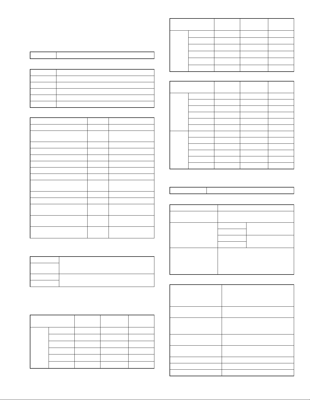
C. Copy speed
(1) Scan One Print many
AR-162 Not available
AR-163
AR-201/F201
AR-206/207
Condition: Copy speed in the normal copy from all the paper feed
ports including the manual paper feed port.
(2) Continuous copy speed (Sheets/min)
a. AR-162/163
Paper size Normal
A3 9 9 9
B4 10 10 10
AB
system
A4 16 16 14
A4R 12 12 12
B5 16 16 16
B5R 14 14 14
(Available for AR-163 for North America,
AR-DE6
AR-PA1 AR-F201 standard
AR-MM5
AR-MM6
AR-MM7
Australia, Asia)
Available
Enlargement
(200%)
Reduction
(50%)
Paper size Normal
11" × 17" 9 9 9
8.5" × 14" 10 10 10
Inch
system
b. AR-201/206/207/F201
system
system
8.5" × 13" 11 11 11
8.5" × 11" 16 16 14
8.5" × 11"R 12 12 12
8.5" × 5.5" 16 16 16
Paper size Normal
A3 11 11 11
B4 12 12 12
AB
A4 20 20 20
A4R 14 14 14
B5 20 20 20
B5R 16 16 16
11" × 17" 10 10 10
8.5" × 14" 12 12 12
Inch
8.5" × 13" 12 12 12
8.5" × 11" 20 20 20
8.5" × 11"R 15 15 15
8.5" × 5.5" 20 20 20
Enlargement
(200%)
Enlargement
(200%)
Reduction
(50%)
Reduction
(50%)
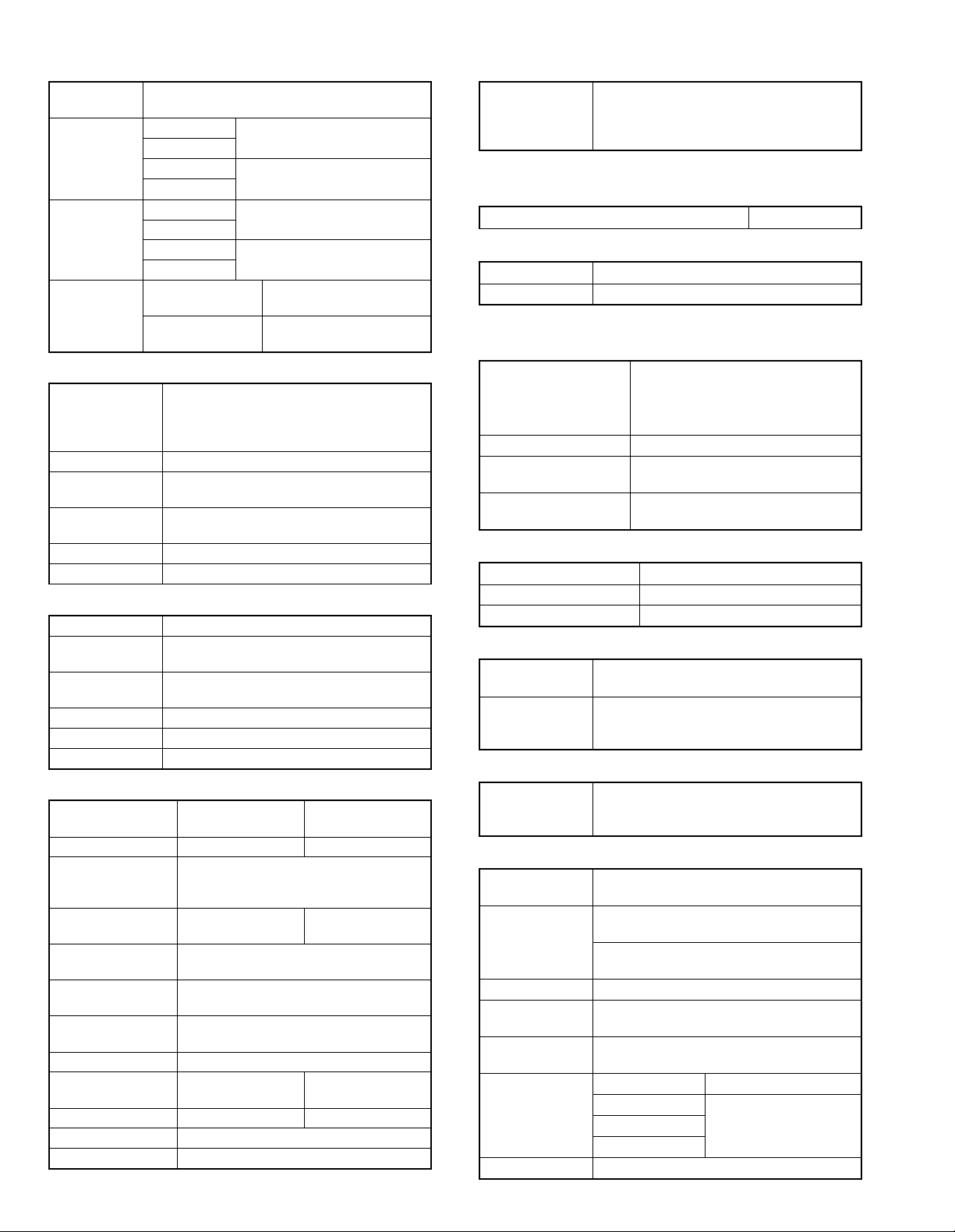
D. First copy time
(1) Basic speed
First copy time 7.2sec (A4, 8.5" × 11"/1st tray/with OC)
E. Document
Max. document size A3, 11" × 17"
Document reference
position
Detection (Platen) AR-162 None
Detection size A3, B4, A4, A4R, B5, B5R, A5
(1) SPF/R-SPF
Standard/Option Option
Document load capacity 30 sheets (56 ∼ 90g/m2 equivalent)
Document size
(Max. ∼ Min.)
Document replacement
speed
Document set/Paper feed
direction
Document weight 56 ∼ 90g/m2, 15 ∼ 23.9 lbs
Document size detection On the document feed tray
Document mixture Copy mode: Not Available
Left side center
AR-163
AR-201/F201 Available
AR-206/207
11" × 17", 8.5" × 14",
8.5" × 13", 8.5" × 11",
8.5" × 11"R, 8.5" × 5.5" (8.5" × 13" is
detected by key input.)
SPF; AR-SP2 (AR-F201 standard)
RSPF; AR-RP1 (AR-206 only)
(AR-207 standard)
(15 ∼ 23.9 lbs.)
A3 ∼ A5
11" × 17" ~ 8.5" × 5.5" (8.5" × 5.5",
duplex is inhibited.)
16 sheets/min (A4 × 8.5" × 11"
normal copy)
Face up, Center reference, Paper
feed from the top
AR-162 SPECIFICATIONS – 1
Page 6
F. Paper feed
Copy size
(Max. ∼ Min.)
Paper feed
system
Paper feed
capacity
Remaining
quantity
detection
(1) Paper feed section of the copier
Paper feed size A3, B4, A4, A4R, B5, B5R, A5
Side front Front
Paper feed
capacity
Detection Paper empty detection available,
Weight 56 ∼ 80g/m2 (15 lbs. ∼ 21 lbs.)
Special paper Recycled paper
(2) Manual paper feed section
Paper feed size A3 ∼ A6, 11" × 17" ∼ 8.5" × 5.5"
Paper feed
capacity
Detection Size detection not available, paper empty
Weight 56 ∼ 128g/m2 (15 ∼ 34 lbs.)
Special paper Recycled paper, OHP film, labels
Paper feed Single except for recycled paper
(3) Option paper feed unit
Model AR-DE5 AR-DE6
Paper feed size A3, B4, A4, A4R, B5, B5R
Capacity
(56 ∼ 80g/m2)
Paper weight 56 ∼ 80 g/m
Moisture preserving
heater
Detection Paper empty detection, size detection
Paper size setting User setting (by key input)
External dimensions
(W × D × H)
Weight About 5kg About 10kg
Special paper Recycled paper
Power Supplied from the machine
(A3 ∼ A6) 11" × 17" ∼ 8.5" × 5.5"
AR-162 1 cassette + Multi manual paper
AR-163
AR-201/F201 2 cassette + Multi manual paper
AR-206/207
AR-162 50 × 1 (Paper feed tray) + 100
AR-163
AR-201/F201 250 × 2 (Paper feed tray) + 100
AR-206/207
Cassette section Empty detection available,
Manual tray Only empty detection
11" × 17", 8.5" × 14", 8.5" × 13", 8.5" × 11",
8.5" × 11"R, 8.5" × 5.5" (For A5 and 8.5" ×
5.5", only No. 1 tray available.)
250 sheets (56 ∼ 80g/m2 equivalent) (15 ∼ 21
lbs.)
size detection (by key input)
100 sheets
detection available
1-step paper feed
11" × 17", 8.5" × 14", 8.5" × 13", 8.5" × 11",
About 250 sheets ×
590 × 471 × 88mm
feed
feed
(Multi bypass feed tray)
(Multi bypass feed tray)
size detection by key input
available
2-step paper feed
unit
8.5" × 11"R
About 250 sheets ×
1 step
(15 ∼ 21 lbs.)
None
(by key input)
unit
2 steps
2
590 × 471 ×
173.5mm
G. Job speed
S-S (1st step) 100% (document replacement rate)
(AR-162/163)
80% (document replacement rate)
(AR-201/206/207/F201)
Condition: With SPF
H. Multi copy
Max. number of multi copy 99 sheets
I. Warmup time
Warmup time Approx. 35 sec ∗
Pre-heat Available
* May vary depending on the surrounding temperature.
J. Copy magnification ratio
Fixed magnification ratio AB system: 50, 70, 81, 86, 100, 115,
122, 141, 200%
Inch system: 50, 64, 77, 95, 100, 121,
129, 141, 200%
Zooming 50 ∼ 200%
Independent
zooming/vertical
Independent zooming
(horizontal)
Available (50 ∼ 200%)
Available (50 ∼ 200%)
K. Print density
Density mode Auto/Manual/Photo
No. of manual adjustment 5 steps (Manual/Photo)
Toner save mode Set by the user program
L. Void width
Void area Lead edge 1 ∼ 4mm, rear edge 4mm or less
(Duplex 4mm or less), both sides 4mm or less
Image loss Max. 4mm in total of lead edge and rear
edge, max. 4mm in total of right and left
edges (Normal copy)
M. Auto duplex
Standard/Option Standard provision (AR-206/207 only) (D →
D/D → S enable only when RSPF is installed)
Not available for AR-162/163/201/F201
N. Paper exit/finishing
Paper exit
section capacity
Job separator Job separator, option (AR-TR2)
Full detection Available (Job separator upper step)
Finishing Electronic sort board: Option (AR-EB3)
Electronic sort
capacity
Offset function AR-162 None
Staple function None
Face down 250 sheets
(AR-F201 standard)
Upper: FAX/Printer, Lower: Copier
Upper: 100sheets, Lower 150sheets
(AR-207 standard)
A4 (8.5" × 11") standard document 60 sheets
AR-163 Available (by the shifter)
AR-201/F201
AR-206/207
AR-162 SPECIFICATIONS – 2
Page 7
(1) Electronic sort board (Option AR-207 standard)
Electronic sort Sorting 60 sheets of A4 standard
documents
Grouping 60 sheets of A4 standard
Rotation copy If there is paper of same size as the
document, the image is rotated to copy even
though the paper is set in the different
direction from the document direction.
2 in 1, 4 in 1 Copies of 2 pages or 4 pages are integrated
into one surface. Divided by solid lines,
(Selectable by the user program.)
Edge erase Images surrounding the document are erased
when copying. (Adjustable in 0 ∼ 20mm by the
user program.)
Center erase The image at the center is erased when
copying. (Adjustable in 0 ∼ 20mm by the user
program.)
Margin shift Binding margin is made at the left edge of the
set documents.
documents
O. Additional functions
*
APS
*
AMS
Duplex
Document count ✕
Sorter When the electronic sort board
Independent
zooming
1 set 2 copy Enlargement inhibited, inhibited
Binding margin Shift width 9mm
Edge erase Width 5mm (Adjustable 0 ∼ 20mm)
Black-white
reversion
2 in 1, 4 in 1
Rotation copy
Memory copy
Pre-heat function Conditions set by the user program
Auto power shut
off function
Auto tray
switching
Message display (FAX/Printer extension)
User program
Total counter
: Available
✕ : Not available
∗
: By the document size set key
: When an option is installed
(APS not available by flowing in
during use of SPF/RSPF)
(AMS not available by flowing in
during use of SPF/RSPF)
✕
AR-206/207 only available
installed.
Vertical/Horizontal: 50 ∼ 200%
during the use of SPF
Whole surface only
(AR-201/206/207/F201 and AR-163
✕
for North America, Australia, Asia:
Available)
Conditions set by the user program
(AR-F201 standard)
P. Other specifications
Photoconductor type OPC (Organic Photo Conductor)
Photoconductor drum dia. 30mm
Copy lamp Xenon lamp
Developing system Dry 2-component magnetic brush
development
Charging system Saw teeth charging
Transfer system (+) DC corotron
Separation system (–) DC corotron
Fusing system Heat roller
Cleaning system Contact blade
Q. Package form
Body Body/Accessaries
R. External view
External dimensions
(W × D × H)
Occupying area (W × D) 590 × 531mm
Weight About 32kg (AR-162/163)
590 × 531 × 470 mm (AR-162/163)
590 × 531 × 523mm (AR-201/206)
590 × 531 × 650mm (AR-207/F201)
(When the manual tray is installed.)
About 35.7kg (AR-201)
About 36.2kg (AR-206)
About 43kg (AR-207)
S. Power source
Voltage AC120V, 220V, 230V, 240V ± 15%
Frequency 50/60Hz common
T. Power consumption
Max. power consumption About 1.3KWh
* EnergyStar standard (The 2nd level conformity)
Pre-heat About 60Wh
Auto power shut
off
about 4.8wh (when FAX or the printer
expansion kit is installed)
0wh ⋅
U. Digital performance
Resolution Reading 400 dpi
Writing 600 dpi
Gradation Reading 256 gradations
Writing Binary
AR-162 SPECIFICATIONS – 3
Page 8
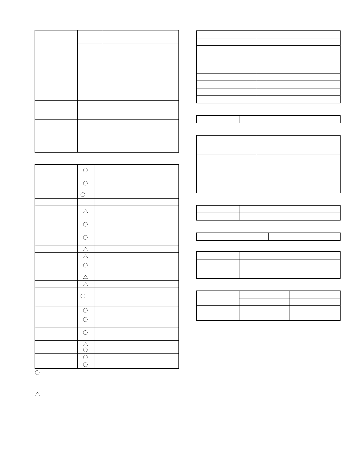
[3] CONSUMABLE PARTS
1. Supply system table
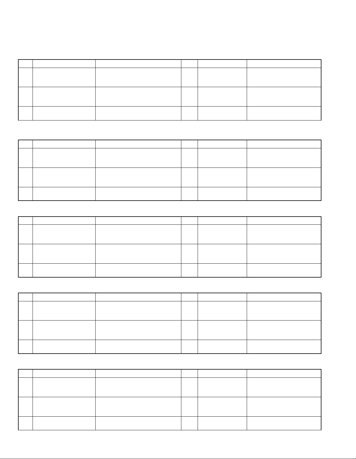
A. USA/CANADA/Latin America
NO Name Content Life Model name Remark
Toner cartridge (Black)
1
<With IC>
Developer Developer × 1
2
Drum kit Drum × 1
3
*1: For USA government
B. Middle East/Africa
NO Name Content Life Model name Remark
Toner cartridge (Black)
1
<With IC>
Developer Developer × 1
2
Drum kit Drum × 1
3
Toner × 1
(Toner: Net Weight 475g)
Vinyl bag × 1
(Developer: Net Weight 400g)
Vinyl bag × 1
Drum fixing plate × 1
Toner × 1
(Toner: Net Weight 475g)
Vinyl bag × 1
(Developer: Net Weight 400g)
Vinyl bag × 1
Drum fixing plate × 1
AR-201NT
13K
(AR-201-J*1)
AR-201ND <Not compatible with the
30K
AR-201DR The AR-201 DR/DM can be used
30K
AR-201FT Life setting by A4 6% document
13K
AR-201SD <Not compatible with the
30K
AR-201DR The AR-201 DR/DM can be used
30K
Life setting by A4 6% document
<Not compatible with the
AR-160/200/225>
AR-160/200/225>
instead of the AR-200 MR/LR/CR.
<Not compatible with the
AR-160/200/225>
AR-160/200/225>
instead of the AR-200 MR/LR/CR.
C. Europe/East Europe
NO Name Content Life Model name Remark
Toner cartridge (Black)
1
<With IC>
Developer Developer × 1
2
Drum kit Drum × 1
3
Toner × 1
(Toner: Net Weight 475g)
Vinyl bag × 1
(Developer: Net Weight 400g)
Vinyl bag × 1
Drum fixing plate × 1
AR-201T Life setting by A4 6% document
13K
AR-201DV <Not compatible with the
30K
AR-201DM The AR-201 DR/DM can be used
30K
<Not compatible with the
AR-160/200/225>
AR-160/200/225>
instead of the AR-200 MR/LR/CR.
D. Asia
NO Name Content Life Model name Remark
Toner cartridge (Black)
1
<With IC>
Developer Developer × 1
2
Drum kit Drum × 1
3
Toner × 1
(Toner: Net Weight 475g)
Vinyl bag × 1
(Developer: Net Weight 400g)
Vinyl bag × 1
Drum fixing plate × 1
AR-201ST Life setting by A4 6% document
13K
AR-201SD <Not compatible with the
30K
AR-201DR The AR-201 DR/DM can be used
30K
<Not compatible with the
AR-160/200/225>
AR-160/200/225>
instead of the AR-200 MR/LR/CR.
E. Hong Kong/China
NO Name Content Life Model name Remark
Toner cartridge (Black)
1
<With IC>
Developer Developer × 1
2
Drum kit Drum × 1
3
Toner × 1
(Toner: Net Weight 475g)
Vinyl bag × 1
(Developer: Net Weight 400g)
Vinyl bag × 1
Drum fixing plate × 1
AR-201ST-C Life setting by A4 6% document
13K
AR-201SD-C <Not compatible with the
30K
AR-201DR-C The AR-201 DR/DM can be used
30K
<Not compatible with the
AR-160/200/225>
AR-160/200/225>
instead of the AR-200 MR/LR/CR.
AR-162 CONSUMABLE PARTS – 1
Page 9
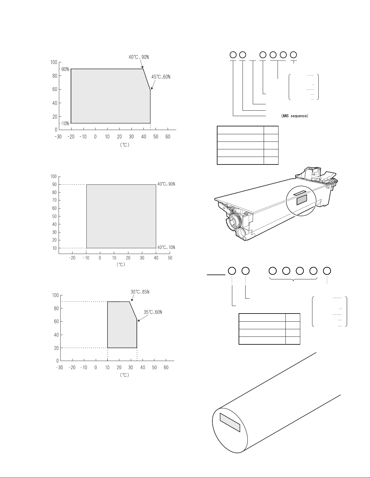
2. Environment conditions
3. Production number identification
A. Transport condition
(1) Transport conditions
Humidity (%)
Temperature
(2) Storage conditions (packed conditions)
<Toner cartridge>
The label on the toner cartridge shows the date of production.
B
Production
∗: Destination
Division No.
Japan option 1
Ex option 2
Japan, same pack 6
Ex, same pack 7
month.
January
Production
day.
Destination
Indicates production in China.
The end digit of production year
Ver.No.
September
October
November
(∗)
December
1
~
~
9
0
X
Y
Humidity (%)
Temperature
B. Use conditions
Use environment
conditions
Humidity (%)
Temperature
C. Life (packed conditions)
Photoconductor drum (36 months from the production month)
Developer, toner (24 months from the production month)
<Drum cartridge>
The label on the drum cartridge shows the date of production.
Ver. A
The end digit of production year
1
Serial number (for each
month) (00001-99999)
Factory
Division No.
Ex production 1
Option 2
Same pack 3
Production
month
January
~
September
October
November
December
1
~
9
0
X
Y
AR-162 CONSUMABLE PARTS – 2
Page 10
[4] EXTERNAL VIEWS AND INTERNAL STRUCTURES
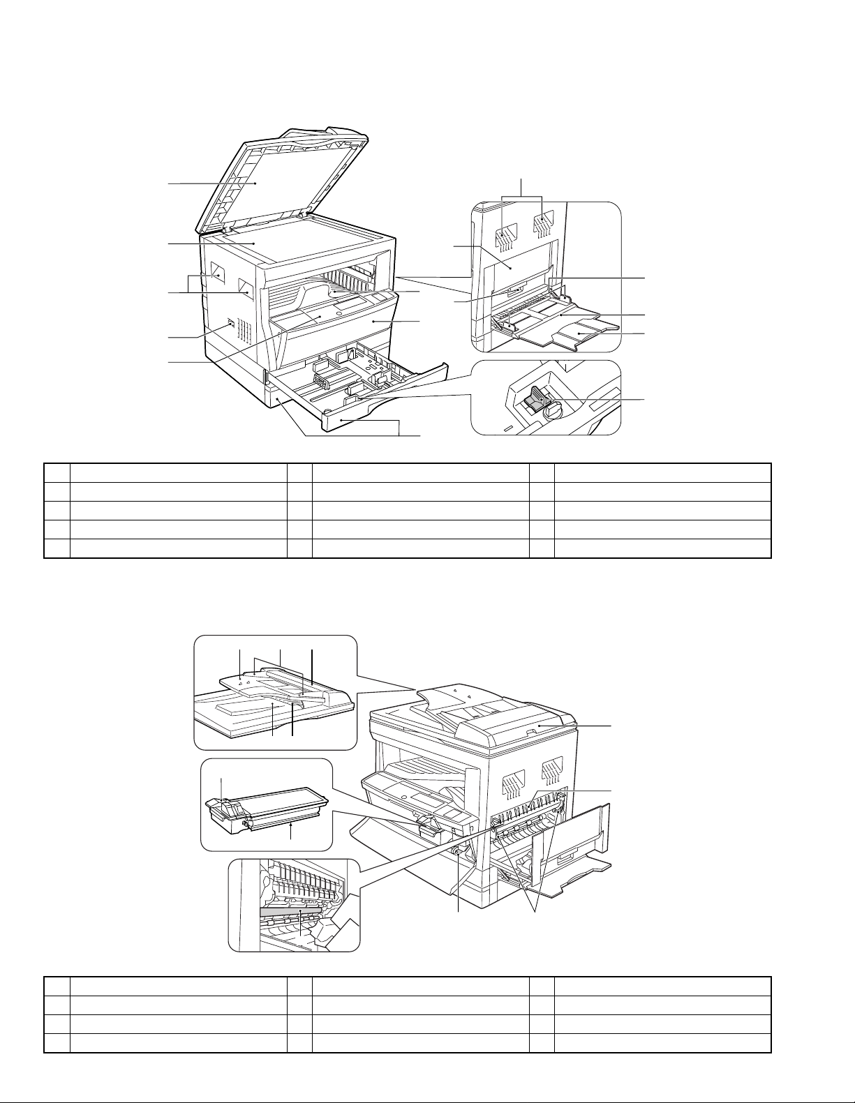
1. Appearance
1
2
3
4
5
1 Document feeder cover 2 Original table 3 Handles
4 Power switch 5 Operation panel 6 Paper output tray
7 Front cover 8 Paper trays 9 Side cover
10 Side cover handle 11 Bypass tray guides 12 Bypass tray
13 Bypass tray extension 14 Charger cleaner
∗ The AR-162/163 are equipped with one paper tray.
9
6
10
7
8
3
11
12
13
14
2. Internal
Reversing single pass feeder (RSPF)
1
6
1 Document feeder tray 2 Original guides 3 Feeding roller cover
4 Exit area 5 Reversing tray 6 Toner cartridge lock release lever
7 Toner cartridge 8 Photoconductive drum 9 Roller rotating knob
10 Fusing unit release levers 11 Right side cover 12 Paper guide
3
2
11
4
5
12
7
9
8
10
AR-162 EXTERNAL VIEWS AND INTERNAL STRUCTURES – 1
Page 11
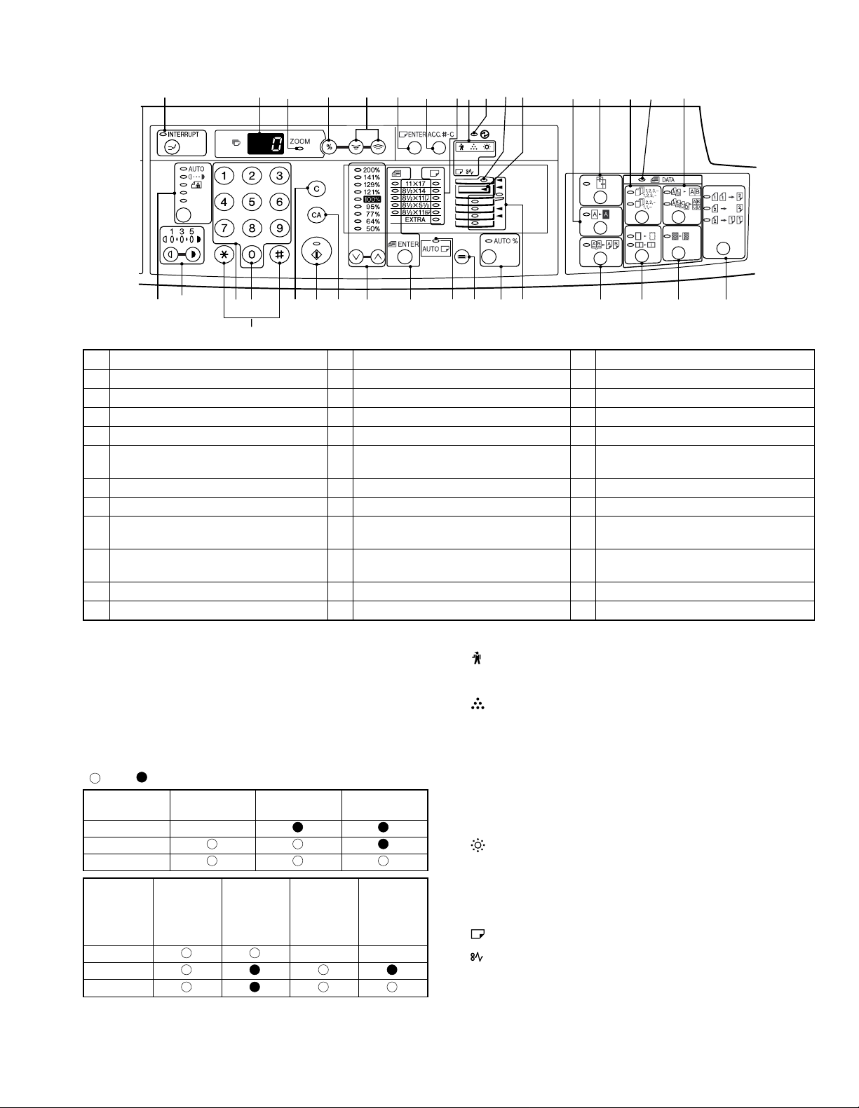
3. Operation Section
1234567891011121314151617
18 19 20 22 23 24 25 26 27 28 29 30 31 32 343321
Not used for the copier features.
1 INTERRUPT key and indicator 2 Copy quantity display 3 ZOOM indicator
4 Copy ratio display key 5 Zoom keys 6 PAPER SIZE ENTER key
7 AUDIT CLEAR key 8 PAPER SIZE indicators 9 Alarm indicators ∗2
10 POWER SAVE indicator 11 SPF/RSPF indicator 12 Output tray full indicator
13 B/W REVERSE key and indicator 14 XY-ZOOM key and indicator 15 SORT/GROUP key and indicators
16 ORIGINAL DATA indicator 17 2 IN 1 / 4 IN 1 key and indicators 18 AUTO/MANUAL/PHOTO key and
indicators
19 Light and dark keys and indicators ∗3 20 Numeric keys 21 Zero key ∗4
22 CLEAR key 23 START key and indicator 24 CLEAR ALL key
25 PRESET RATIO selector keys and
indicators
28 TRAY SELECT key 29 AUTO IMAGE key and indicator 30 Paper feed location/misfeed location
31 DUAL PAGE COPY key and indicator 32 ERASE key and indicators 33 MARGIN SHIFT key and indicator
34 ORIGINAL TO COPY key and indicators
26 ORIGINAL SIZE ENTER key and
indicators
27 AUTO PAPER SELECT indicator
indicators
∗1
ON: Indicates that the machine is in the energy saving (pre-heat)
mode.
Blink: Indicates that the machine is in the process of resetting from
the energy saving mode or just after supplying the power.
(During warmup)
OFF: Indicates that resetting from the energy saving mode is com-
pleted and that the fusing temperature is in ready state.
The combinations of the above display lamps are as follows:
( = ON, = OFF)
Lamp
Pre-heat lamp Blink
Ready lamp
Other lamps
Lamp
Pre-heat lamp Blink Blink
Ready lamp
Other lamps
Immediately after
power ON
Energy
saving mode
(Pre-heating)
Energy
saving mode
(Auto power
shut off)
Ready Copying
Resetting
from energy
saving mode
Copy is
started during
resetting from
energy saving
mode
∗2
Maintenance indicator
When the set count number (set by the simulation) is reached,
the lamp lights up. The machine does not stop.
Toner cartridge replacement required indicator
When toner density is lower than a specified level, the TONER
CARTRIDGE REPLACEMENT indicator lights up to warn the
user.
If toner is not added after approximately 10% is copied, the
indicator starts blinking and machine starts to supply toner.
(Toner cartridge replacement indicator keeps lighting up)
If toner density is not back to specific level after two minutes, the
READ indicator goes out and Toner indicator starts blinking, and
the copier stops.
Developer replacement required indicator
(1) Lights up when the developer counter reaches 30K.
(2) Selection between STOP and NON-STOP is allowed with the
service simulation No.
(Default: NON-STOP)
Paper required indicator
Misfeed indicator
∗3 Light key
Press and hold this key for 5 sec, and the machine will enter the
user program mode.
∗4 Zero key
Press and hold this key, and the total output counter value is
displayed on the copy quantity display.
AR-162 EXTERNAL VIEWS AND INTERNAL STRUCTURES – 2
Page 12
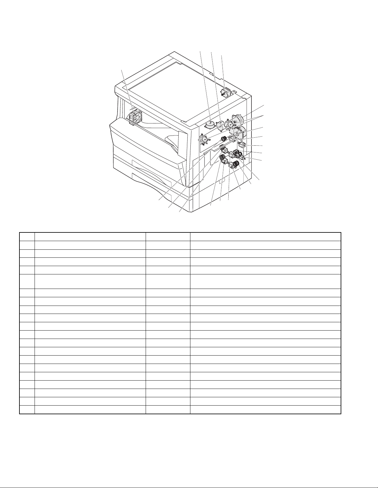
4. Motor, solenoid, clutch
2
3
4
1
5
6
7
8
9
10
11
12
13
14
20
19
18
17
16
15
No. Name Code Function, operation
1 Exhaust fan motor VFM Cools the inside of the machine.
2 Shifter motor SHTM Shifts the paper exit tray. (Except for the AR-162)
3 Toner motor TM Toner supply
4 Mirror motor MRM Drives the optical mirror base (scanner unit).
5 Duplex motor DPX Switchback operation and paper exit motor in duplex. (only
AR-206/207)
6 Cooling fan motor CFM Cools the inside of the machine.
7 Main motor MM Drives the machine.
8 Paper feed solenoid CPFS1 Solenoid for paper feed from cassette
9 Resist roller solenoid RRS Resist roller rotation control solenoid
10 Manual paper feed clutch MPFC Drives the manual paper feed roller.
11 Manual paper feed solenoid MPFS Manual paper feed solenoid
12 Manual paper transport clutch MPTC Drives the manual paper transport roller.
13 2nd tray transport clutch CPFC2 Drives the 2nd tray transport roller.
14 2nd tray transport solenoid FSOL2 2nd tray transport solenoid
15 1st tray transport solenoid FSOL1 1st tray transport solenoid
16 2nd tray paper feed solenoid PSOL2 2nd tray transport solenoid
17 Paper feed clutch CPFC2 Drives the cassette paper feed roller.
18 1st tray paper feed solenoid PSOL1 1st tray transport solenoid
19 1st tray paper feed clutch CPFC1 Drives the 1st tray transport roller.
20 PS clutch RRC Drives the resist roller
AR-162 EXTERNAL VIEWS AND INTERNAL STRUCTURES – 3
Page 13
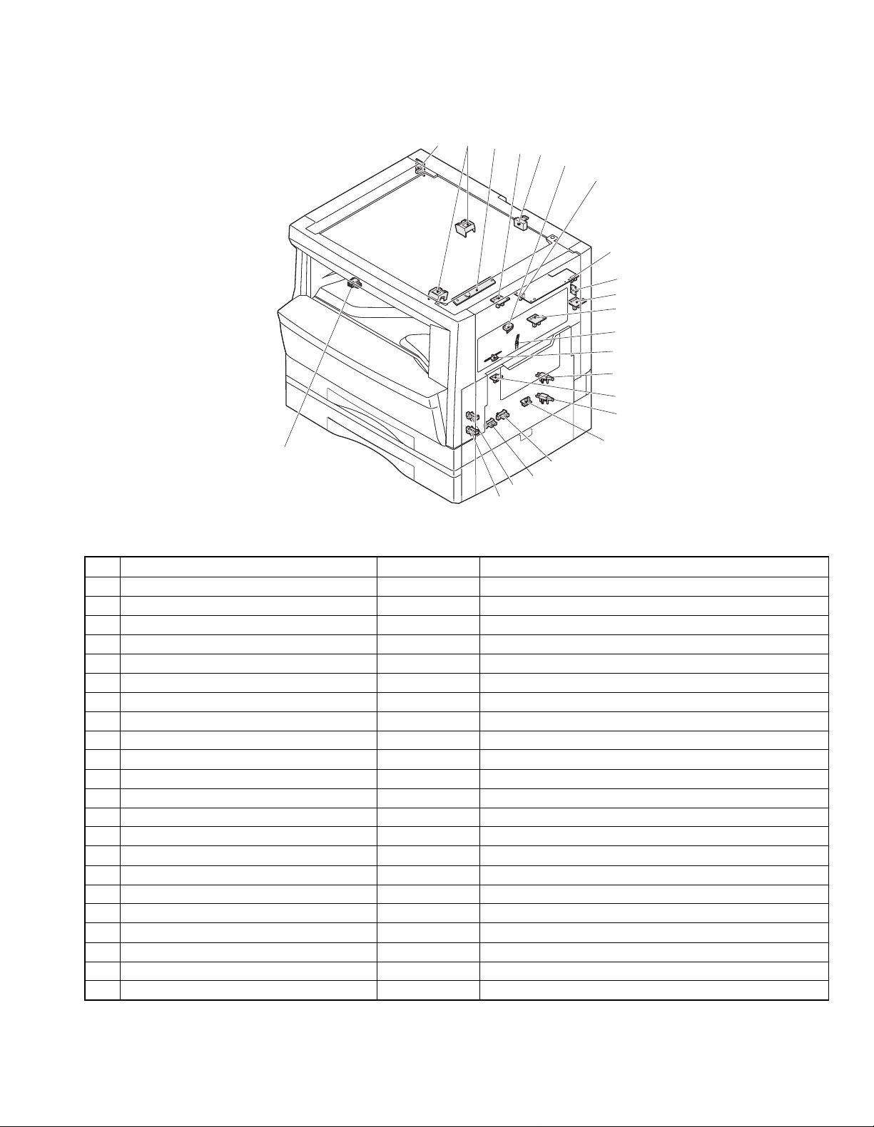
5. Sensor, switch
22
123
20
21
4
5
6
7
8
9
10
11
12
13
14
15
16
17
18
19
No. Name Code Function, operation
1 Mirror home position sensor MHPS Detects the mirror (scanner unit) home position.
2 Document size sensor DSIN Paper size detection
3 Toner density sensor TCS Toner quantity detection
4 Paper exit sensor (paper exit side) POD1 Detects paper exit.
5 OC open/close sensor DOC COVER Detects open/close of OC/SPF.
6 Right door switch DSWR Side door open/close detection
7 Paper full sensor P FULL Paper exit tray section full detection <For JOB separator>
8 Lift sensor LFTHP Paper feed tray lift up detection <For JOB separator>
9 Lower limit sensor JTRAY Job separator tray lower limit detection
10 Paper exit sensor (DUP side) PDPX Paper transport detection
11 Shifter home position sensor SFTHP Shifter home position detection (Excluding AR-162)
12 Thermistor RTH Fusing section temperature detection
13 Thermostat Fusing section abnormally high temperature detection
14 1st tray detection switch 1st tray detection
15 Paper in PIN Paper transport detection
16 2nd tray detection switch 2nd tray detection (Excluding AR-162/163)
17 Manual sensor MPED Manual transport detection
18 2nd tray door open/close sensor DRS2 2nd tray door open/close detection (Excluding AR-162/163)
19 2nd tray paper entry sensor PPD2 Paper transport detection (Excluding AR-162/163)
20 1st tray paper empty sensor CSS1 1st tray paper empty detection
21 2nd tray paper empty sensor CSS2 2nd tray paper empty detection (Excluding AR-162/163)
22 Power switch MAIN SW Turns ON/OFF the main power source.
AR-162 EXTERNAL VIEWS AND INTERNAL STRUCTURES – 4
Page 14
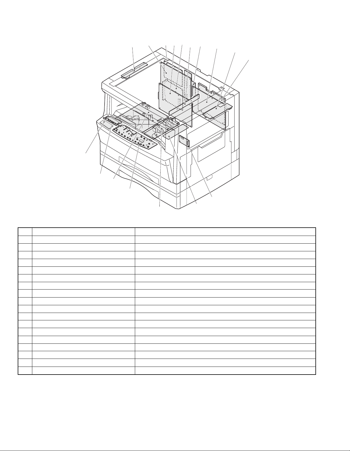
6. PWB unit
16
15
14
13
3
5
2
1
4
6
7
8
9
10
11
12
17
No. Name Function, operation
No. Name Function, operation
1 Copy lamp Inverter PWB Copy lamp control
2 FAX main PWB Fax communication control <AR-F201 or Option>
3 TEL/LIU PWB Line control (Fax communication) <AR-F201 or Option>
4 Printer control PWB Printer control <Option>
5 Network Board Network system interface <Option>
6 CCD sensor PWB Image scanning
7 Mother PWB Connecting the MCU and Printer/FAX PWB <AR-F201 or Option>
8 Main PWB (MCU) Machine control/Image process
9 Paper exit interface PWB Paper exit, finishing control
10 Electronic sort PWB Electronic sort function control <AR-207 or Option>
11 Tray interface PWB Paper tray control
12 High voltage PWB High voltage control
13 Operation main PWB Operation panel input/Display, operation panel section control
14 Power PWB AC power input/DC power control
15 LCD PWB Printer and FAX status display <AR-F201 or Option>
16 Fax operation PWB Operation for FAX <AR-F201 or Option>
17 CRUM PWB Saving toner cartridge data
AR-162 EXTERNAL VIEWS AND INTERNAL STRUCTURES – 5
Page 15
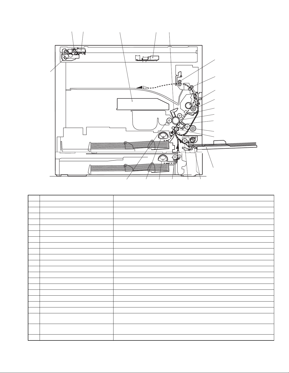
7. Cross sectional view
12 3 45
6
17
7
8
9
10
11
12
13
14
15
1819202122
16
No. Name Function/Operation
1 Copy lamp Image radiation lamp
2 Copy lamp unit Operates in synchronization with No. 2/3 mirror unit to radiate documents sequentially.
3 LSU unit Converts image signals into laser beams to write on the drum.
4 Lens unit Reads images with the lens and the CCD.
5 MC holder unit Supplies negative charges evenly on the drum.
6 Paper exit roller Used to discharge paper.
7 Transport roller Used to transport paper.
8 Upper heat roller Fuses toner on paper (with the teflon roller).
9 Lower heat roller Fuses toner on paper (with the silicon rubber roller).
10 Waste toner transport roller Transports waste toner to the waste toner box.
11 Drum unit Forms images.
12 Transfer charger unit Transfer images (on the drum) onto paper.
13 Duplex transport roller Transports paper for duplex (only AR-206/207).
14 Resist roller Takes synchronization between the paper lead edge and the image lead edge.
15 Manual paper feed tray Manual paper feed tray
16 Manual paper feed roller Picks up paper in manual paper feed.
17 No. 2/3 mirror unit Reflects the images from the copy lamp unit to the lens unit.
18 Manual transport roller Transports paper from the manual paper feed port.
19 2nd tray paper transport roller Transports paper from the 2nd tray. (Excluding AR-162/163)
20 2nd tray paper feed roller
(semi-circular roller)
21 1st tray paper feed roller
(semi-circular roller)
22 MG roller Puts toner on the OPC drum.
Picks up paper from the 2nd tray. (Excluding AR-162/163)
Picks up paper from the 1st tray.
AR-162 EXTERNAL VIEWS AND INTERNAL STRUCTURES – 6
Page 16
[5] UNPACKING AND
INSTALLATION
1. Installing conditions
1) Copier installation
Do not install your copier in areas that are:
• damp, humid, or very dusty
• exposed to direct sunlight
• poorly ventilated
• subject to extreme temperature or humidity changes, e.g., near an
air conditioner or heater.
• Be sure to allow the required space around the machine for servic-
ing and proper ventilation.
4" (10 cm)
2) Power source
• Use an exclusive-use power outlet. If the power plug of this
machine is inserted into a power outlet commonly used with other
illumination units, flickers of the lamp may be result. Use a power
outlet which is not used commonly with any illumination units.
• Avoid complex wiring.
3) Grounding wire connection.
• To avoid danger, be sure to connect a grounding wire. If no
grounding wire is connected and a leakage occurs, a fire or an
electric shock may be result.
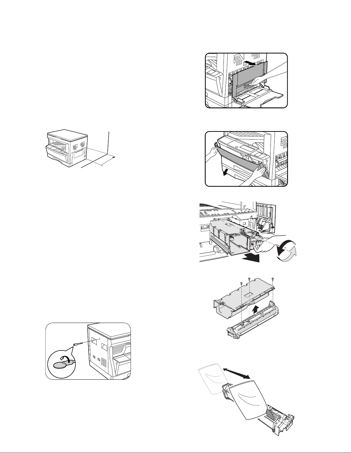
3. Installing procedure
A. Developer cartridge installation
1) Open the manual tray, and open the side cover.
2) Open the front cover.
• Hold the both sides and pull down to open.
3) Loosen the screw and remove the developer cartridge.
2. Removal of protective material and
fixing screw
1) Remove all tapes and protective material.
• Remove all tapes, then open the document cover and remove
the protective material of sheet shape
2) Remove the fixing screw.
• Use a coin to remove the fixing screw.
• The fixing screw is required when transporting the machine.
Keep it in the tray. (Refer to the later description.)
4) Remove the developer tank from the developer cartridge.
5) Supply developer into the developer tank while rotating the MG
roller.
* Shake the developer bag enough before opening it.
AR-162 UNPACKING AND INSTALLATION – 1
Page 17
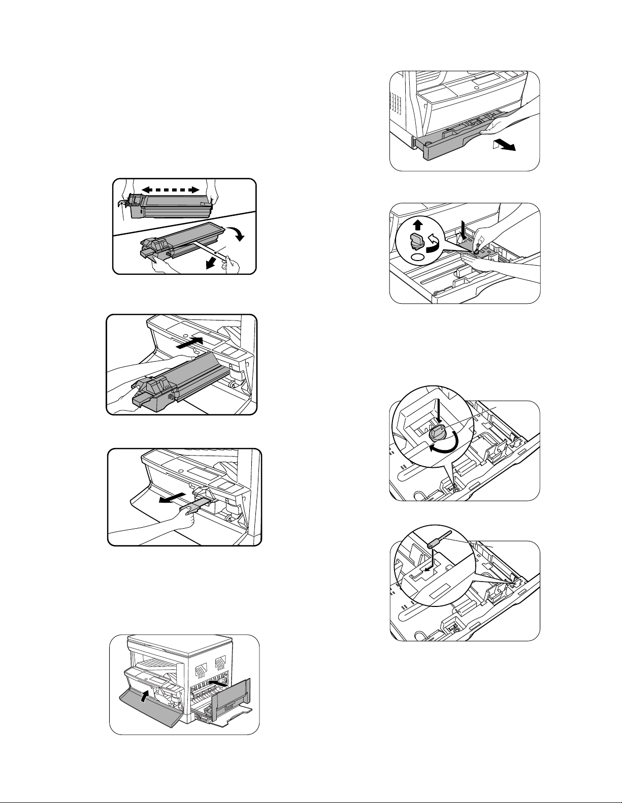
6) Attach the developer tank to the developer cartridge.
* After supplying developer into the developer cartridge, do not
tilt or shake the developer cartridge.
7) Attach the developer cartridge to the copier, and fix it with the
screw.
B. Toner cartridge installation
1) Shake the toner cartridge several times horizontally, and remove
the tape.
* Do not hold the shutter lever when shaking.
* After removing the tape, do not tilt or shake the toner cartridge.
4. Removal and storage of fixing screw
1) Lift the knob and gently pull out the tray.
4 or 5 times
Shutter
2) Attach the toner cartridge to the copier.
3) Pull the shutter lever.
2) Hold the paper pressure plate and turn the fixing screw in the
arrow direction.
Tape
3) Store the fixing pin and the fixing screw in the tray.
• Store the fixing screw which was removed in the above proce-
dure 2 and the fixing screw which was removed in procedure 2
of 2.
• Removal of protective material and fixing screw in the storage
place in the tray.
Pressure
plate
lock
Close the front cover A, then close the side cover B.
• When closing the front cover, gently press the both sides.
• When closing the side cover, hold the knob.
• When closing the covers, be sure to close the front cover first,
then close the side cover. If closed in a wrong sequence, the
covers may be broken.
B
A
AR-162 UNPACKING AND INSTALLATION – 2
Screw
Page 18
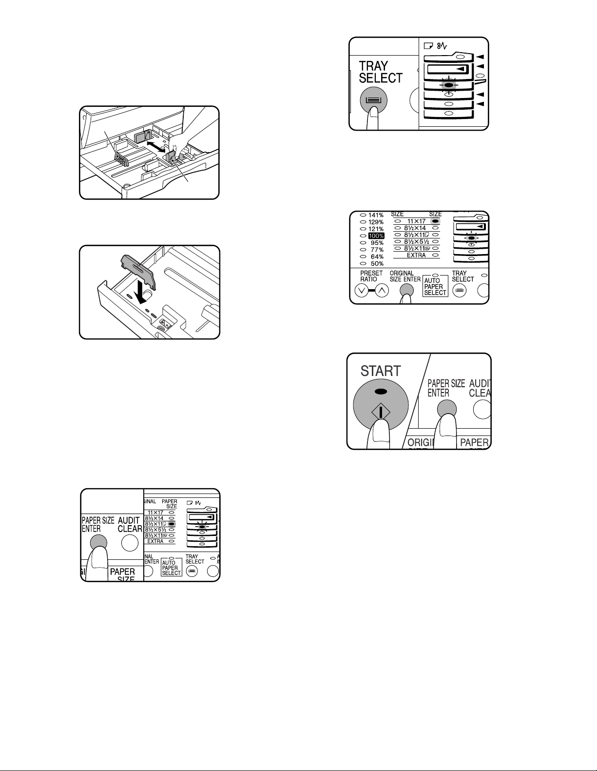
5. Changing the copy paper size in the tray
1) Gently lift and pull out the paper tray until it stops.
2) Push the pressure plate down until it locks in place.
3) Squeeze the lock lever of the front guide and slide the front guide
to match the width of the paper.
Left guide
Front guide
4) Move the left guide to the appropriate slot as marked on the tray.
• When using 11" ×17" copy paper, store the left guide in the slot
at the left front of the paper tray.
5) Load copy paper into the tray.
6) Place the paper size plate in the front of the paper tray.
• The paper size indication which shows through the slot on the
front of the copier should match the selected paper size.
7) Push the paper tray firmly back into the copier.
8) To set the selected paper size, press and hold down the PAPER
SIZE ENTER key. The selected paper feed location indicator and
the corresponding paper size (which has been set) indicator will
blink. All other indicators will go out.
• For paper size setting, ensure that the COPY mode has been
selected. However, if printer or facsimile output is being performed, paper size setting cannot be made even in the COPY
mode.
10) Use the ORIGINAL SIZE ENTER key to select the paper size
which is set.
• Each time the ORIGINAL SIZE ENTER key is pressed, a
paper size will be indicated with a blinking paper size indicator.
11) Press the START key and then the PAPER SIZE ENTER key.
• To change the paper size setting of another tray, repeat steps
9 to 10 after pressing the START key.
9) Use the TRAY SELECT key to select the paper tray of which the
paper size has been changed.
• Each time the TRAY SELECT key is pressed, a paper tray is
indicated with a blinking paper feed location indicator. If an
optional paper feed unit is not installed, this operation is not
needed.
AR-162 UNPACKING AND INSTALLATION – 3
Page 19
[6] ADJUSTMENTS
Section Adjustment item Adjustment procedure/SIM No.
A Process
section
(1) Developing doctor gap adjustment Developing doctor gap adjustment
(2) MG roller main pole position adjustment MG roller main pole position adjustment
(3) Developing bias voltage output adjustment
(4) Main charger voltage output adjustment
B Mechanism
section
(1) Image lead edge position adjustment SIM 50-1
(2) Main scanning direction (FR direction) distortion
balance adjustment
No. 2/3 mirror base unit installing position adjustment
Copy lamp unit installing position adjustment
(3) Main scanning direction (FR direction) distortion
adjustment
Rail height adjustment
(4) Sub scanning direction (scanning direction) distortion
adjustment
Winding pulley position adjustment
(5) Main scanning direction (FR direction) magnification
ratio adjustment
SIM 48-1
(6) Sub scanning direction (scanning direction)
magnification ratio adjustment
a OC mode in copying (SIM 48-2)
b SPF mode in copying (SIM 48-5)
c OC mode in FAX (SIM 48-6)
d SPF mode in FAX (SIM 48-7)
(7) Off center adjustment a OC mode (SIM 50-13)
b SPF mode (SIM 50-16)
(8) OC (SPF) open/close detection position adjustment OC (SPF) open/close detection position adjustment
(9) Document size detection sensor SIM 41-3
C Image density
adjustment
(1) Copy mode SIM 46-1
2. Copier adjustment
A. Process section
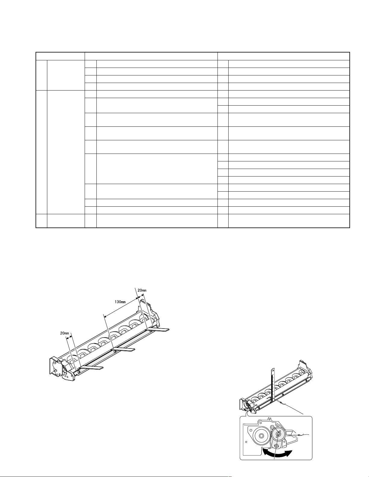
(1) Developing doctor gap adjustment
1) Loosen the developing doctor fixing screw A.
2) Insert a thickness gauge of 1.5mm to the three positions at 20mm
and 130mm from the both ends of the developing doctor as
shown.
3) Push the developing doctor in the arrow direction, and tighten the
developing doctor fixing screw. (Perform the same procedure for
the front and the rear frames.)
4) Check the clearance of the developing doctor. If it is within the
specified range, then fix the doctor fixing screw with screw lock.
* When inserting a thickness gauge, be careful not to scratch the
developing doctor and the MG roller.
<Adjustment specification>
Developing doctor gap
Both ends (20mm from the both ends):
1.5
−0.15
+0.1
mm
C (Center)(150mm from the both ends): 1.55
−0.2
+0.15
mm
(2) MG roller main pole position adjustment
1) Remove and separate the waste toner box and put the developing
unit on a flat surface.
2) Tie a string to a needle or a pin.
3) Hold the string and bring the needle close to the MG roller
horizontally. (Do not use paper clip, which is too heavy to make a
correct adjustment.) (Put the developing unit horizontally for this
adjustment.)
4) Do not bring the needle into contact with the MG roller, but bring it
to a position 2 or 3mm apart from the MG roller. Mark the point on
the MG roller which is on the extension line from the needle tip.
5) Measure the distance from the marking position to the top of the
doctor plate of the developing unit to insure that it is 18mm.
If the distance is not within the specified range, loosen the fixing
screw A of the main pole adjustment plate, and move the adjustment plate in the arrow direction to adjust.
AR-162 [6] ADJUSTMENT 11/1/2000
AR-162 ADJUSTMENTS – 1
1. Adjustment item list
Page 20
(3) Developing bias voltage adjustment
5
10
5mm
4mm
*The dimension varies depending on the model.
10
5mm
0mm
5
* The scanning edge is set.
(A line may be printed by scanning the document edge.)
AR-162 [6] ADJUSTMENT 11/1/2000
AR-162 ADJUSTMENTS – 2
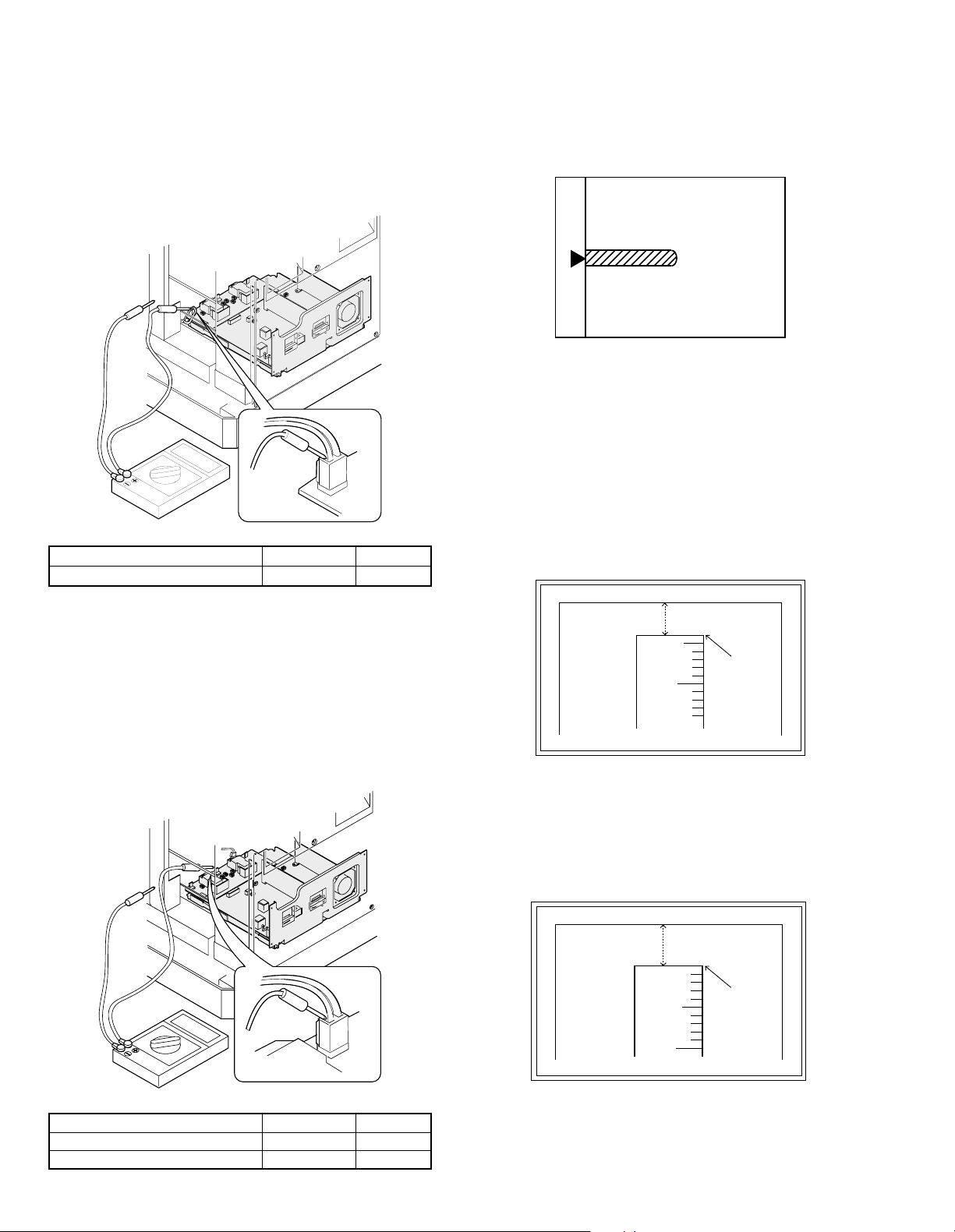
Note: • Use a digital multi-meter with an internal resistance of
10MΩ or more.
1) Set the digital multi-meter range to DC700V.
2) Put the test rod of the digital multi-meter on the developing bias
voltage output check pin.
3) Turn on the power.
4) Adjust the adjustment volume VR31 so that the output voltage is
within the specified range shown below.
<Adjustment specification>
Mode Specification
Developing bias voltage DC-400±8V VR31
B. Mechanism section
(1) Image lead edge position adjustment (SIM 50-1)
a. OC image lead edge position adjustment
Note: In advance to this adjustment, the sub scanning magnification
ratio adjustment must be performed.
1) Set a scale on the OC table as shown below.
2) Make a copy.
3) Check the copy output. If necessary, perform the following adjustment procedures.
4) Execute SIM 50-1.
5) Set the OC lead edge position set value (Exposure display
<AUTO> ON) to “99.”
The OC image scanning start position is shifted inside the document edge.
6) Set the main cassette lead edge void adjustment value (Exposure
display <PHOTO> ON) * to “1.”
The lead edge void becomes the minimum.
7) Set the print start position value (Exposure display <EXP1> ON)
to “99” and make a copy.
The print start position is shifted inside the document edge.
(4) Grid bias voltage adjustment
Note: • Use a digital multi-meter with an internal resistance of
1) Set the digital multi-meter range to DC700V.
2) Put the test rod of the digital multi-meter on the grid bias voltage
3) Turn on the power.
4) Adjust the adjustment volumes (VR51, VR52) so that the output
<Adjustment specification>
10MΩ or more.
output check pin.
voltage is within the specified range. (The voltage is outputted in
the grid bias high output mode during warming up, and in the grid
bias low output mode after completion of warming up.)
Mode Specification
Grid bias LOW DC-400±20V VR52
Grid bias HIGH DC-525±10V VR51
8) Measure the image loss R of the copied image. Enter the set
value of the image scanning lead edge position (Exposure display
<AUTO> ON) again.
• 1 step of the set value corresponds to about 0.127mm shift.
• Calculate the set value from the formula below.
99 - R/0.127 (mm) = Image loss set value <R: Image loss measurement value (mm)>
Example: 99 - 4/0.127 = 99 - 31.5 = about 67
Note: If the set value is not obtained from the above formula,
perform the fine adjustment.
Page 21
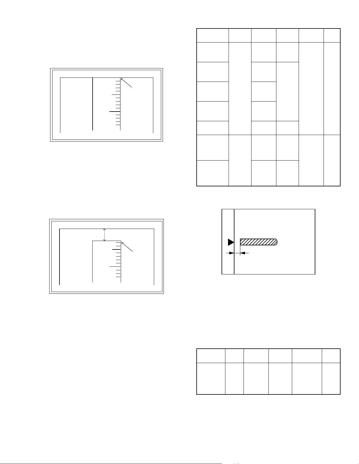
9) Measure the distance H between the paper lead edge and the
5
10
0mm
0mm
*Fit the print edge with the paper edge, and perform the
lead edge adjustment.
5
10
2.5mm
2.5mm
AR-162 [6] ADJUSTMENT 11/1/2000
AR-162 ADJUSTMENTS – 3
image print start position. Set the image print start position set
value (Exposure display <EXP1> ON) again.
• 1 step of the set value corresponds to about 0.127mm shift.
• Calculate the set value from the formula below.
99 - H/0.127 (mm) = Image print start position set value <H: Print
start position measurement value (mm)>
Example: 99 - 5/0.127 = 99 - 39.4 = about 59
Note: If the set value is not obtained from the above formula,
perform the fine adjustment.
10)Set the main cassette lead edge void adjustment value (Exposure
display <PHOTO> ON)* again.
• 1 step of the set value corresponds to about 0.127mm shift.
• Calculate the set value from the formula below.
B/0.127 (mm) = Lead edge void adjustment value <B: Lead edge
void (mm)>
<Adjustment specification>
Adjustment
mode
OC image
lead edge
position
Main
cassette lead
edge void
2nd tray lead
edge void
Multi bypass
tray lead
edge void
Print start
position
OC 2nd print
surface lead
edge position
adjustment
OC 2nd print
surface lead
edge void
adjustment
* (Set to S → D mode for before execution)
b. SPF image lead edge position adjustment
1) Set a scale on the OC table as shown below.
SIM LED Set value
99
R/0.127
B/0.127
99 –
H/0.127
1 step:
0.127mm
shift
1 step:
0.127mm
shift
SIM
50-1
SIM
50-1*
AUTO
PHOTO
AUTO +
MANUAL
+ PHOTO
MANUAL
+ PHOTO
EXP1
EXP 3
No display
Spec
value
Lead
edge
void: 1 -
4mm
Image
loss: 3mm
or less
Set
range
1 ∼ 99
Example: When setting the lead edge void to 2.5mm:
2.5 /0.127 = about 20
Note: If the set value is not obtained from the above formula,
perform the fine adjustment.
* 2nd tray lead edge void adjustment: Exposure display <AUTO
+ MANUAL + PHOTO>
Multi bypass tray lead edge void adjustment: Exposure display
<MANUAL + PHOTO>
OC 2nd print surface (Auto duplex) lead edge position adjustment:
Density display <EXP3>
OC 2nd print surface (Auto duplex) lead edge void adjustment:
Exposure display <None>
* For the adjustment procedure, set to S → D mode
Note: Before performing the 2nd print surface lead edge position
adjustment and the lead edge void adjustment, be sure to
perform the 1st print surface lead edge position adjustment
in advance, and be sure to perform the 2nd print surface
lead edge position adjustment and then the lead edge void
adjustment in this sequence.
Note: Since the printed copy is used as a test chart, put the scale in
paralled with the edge lines.
2) Make a copy, Then use the copy output as an original to make an
SPF copy again.
3) Check the copy output. If necessary, perform the following adjustment procedures.
4) Execute SIM 50-1.
5) Set the SPF lead edge position set value (Exposure display
<MANUAL> ON) so that the same image is obtained as that obtained in the previous OC image lead edge position adjustment.
<Adjustment specification>
Adjustment
mode
SPF image
lead edge
position
SIM LED Set value Spec value
Lead edge
void: 1 -
4mm
Image loss:
3mm or less
SIM
50-1
MANUAL
1 step:
0.127mm
shift
Set
range
1 ∼ 99
Page 22
c. Rear edge void adjustment
A4(8.5" x 11")
Paper rear edge
Scale image
Paper rear edge
Void amount (Standard value: 4mm or less)
AR-162 [6] ADJUSTMENT 11/1/2000
AR-162 ADJUSTMENTS – 4
1) Set a scale as shown in the figure below.
2) Set the document size to A4 (8.5" × 11"), and make a copy at
100%.
3) If necessary, perform the following adjustment procedure.
4) Execute SIM 50-1 and set the density mode to AUTO + PHOTO
(Rear edge void).
The currently set adjustment value is displayed.
5) Enter the set value and press the start key.
The correction value is stored and a copy is made.
* 2nd print surface (auto duplex) rear edge void adjustment: Ex-
posure display <EXP 5>
* Set to S → D mode before execution.
Note: Before performing the 2nd print surface rear edge void
adjustment, be sure to perform the 2nd print surface lead
edge position adjustment. Never reverse the sequence.
<Adjustment specification>
Mode SIM LED Set value
Rear edge
void
SIM 50-1
AUTO +
PHOTO
2nd print
surface rear
SIM 50-1∗EXP 5
edge void
1 step:
0.127mm
shift
Specifi-
cation
4mm or
less
4mm or
less
Set
range
1 ∼ 99
∗ Set to S → D mode before execution
d. Paper off center adjustment
1) Execute SIM 50-1 and set the density mode of AUTO + MANUAL
(Left edge void) to 1.
2) Set a test chart (UKOG-0089SCZZ) on the document table.
3) Select a paper feed port and make a copy.
Compare the copy and the test chart. If necessary, perform the
following adjustment procedure.
4) Execute SIM 50-10.
After completion of warmup, shading is performed and the currently set off center adjustment value of each paper feed port is
displayed.
5) Enter the set value and press the start key.
The correction value is stored and a copy is made.
* 2nd print surface (auto duplex) off-center adjustment: Exposure
display: None
<Adjustment specification>
Mode SIM LED Set value
Paper off
center
SIM 50-10
Selected
tray ON
Add 1:
0.127mm
shift to R
side.
2nd print
surface
off-center
SIM 50-10
display
No
Reduce 1:
0.127mm
shift to L
side.
Specifi-
cation
Single:
Center
±2.0mm
Duplex:
Center
±2.5mm
Set
range
1 ∼ 99
* When SIM 48-01 (AE) is executed, the document off-center is
automatically set. Therefore, the off-center adjustment previously
described in 5) must be adjusted again.
e. Left edge void area adjustment
Note: Before performing this adjustment, be sure to check that the
paper off center adjustment (SIM 50-10) is completed.
1) Set a test chart (UKOG-0089SCZZ) on the document table.
2) Select a paper feed port and make two copies.
Compare the 2nd copy and the test chart. If necessary, perform
the following adjustment procedure.
* The 1st copy does not show the void. Be sure to check the 2nd
copy.
3) Execute SIM 50-1 and set the density mode to AUTO + MANUAL
(Left edge void).
The currently set adjustment value is displayed.
(When the off center adjustment previously described is performed, "0" is displayed.)
4) Enter the set value and press the start key.
The correction value is stored and a copy is made.
<Adjustment specification>
Mode SIM LED Set value Specification
Left
edge
void
SIM
50-1
AUTO +
MANUAL
1 step:
0.127mm
shift
0.5 ∼ 4mm 1 ∼ 99
Set
range
* When the left edge void is set with the paper off center adjusted,
the both edge void is automatically adjusted.
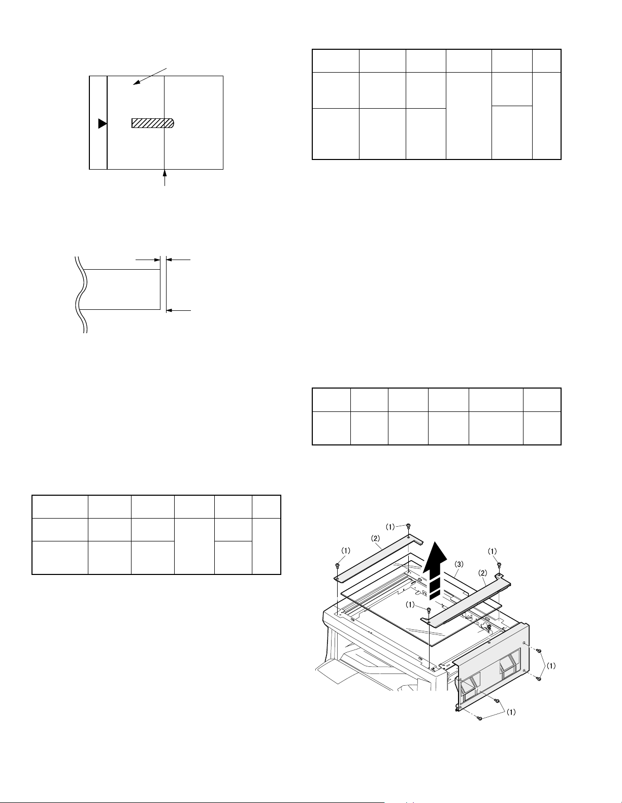
(2) Main scanning direction (FR directional distortion
balance adjustment)
1) Remove the OC glass and the right cabinet.
Page 23

2) Loosen the copy lamp unit wire fixing screw.
Wire fixing screw
AR-162 [6] ADJUSTMENT 11/1/2000
AR-162 ADJUSTMENTS – 5
5) Without moving the scanner drive pulley shaft, manually turn the
scanner drive pulley until the positioning plate is brought into contact with No. 2/3 mirror base unit, then fix the scanner drive pulley.
3) Manually turn the mirror base drive pulley and bring No. 2/3 mirror
base unit into contact with the positioning plate.
At that time, if the front frame side and the rear frame side of No.
2/3 mirror base unit are brought into contact with the positioning
plate at the same time, the mirror base unit parallelism is proper.
If one of them is in contact with the positioning plate, perform the
adjustment of 4).
6) Put No. 2/3 mirror base unit on the positioning plate again, push
the projections on the front frame side and the rear frame side of
the copy lamp unit to the corner frame, and tighten the wire fixing
screw.
4) Loosen the set screw of the scanner drive pulley which is not in
contact with No. 2/3 mirror base unit positioning plate.
Page 24

(3) Main scanning direction (FR direction) distortion
Lb
La
Original
Copy
Paper exit
direction
Fit the paper edge and
the glass holding plate edge.
A3 (11" x 17") white paper
Glass holding plate
Allow a little space.
Paper exit direction
La: Lead edge black background width
Lb: Rear edge black background width
A
B
Rear side
Front side
Original
Copy A Copy B
AR-162 [6] ADJUSTMENT 11/1/2000
AR-162 ADJUSTMENTS – 6
adjustment
This adjustment must be performed in the following cases:
• When the mirror base drive wire is replaced.
• When the lamp unit, or No. 2/3 mirror holder is replaced.
• When a copy as shown is made.
1) Set A3 (11" x 17") white paper on the original table as shown
below.
4) Loosen the mirror base drive pulley fixing screw on the front frame
side or on the rear frame side.
• When La < Lb
Turn the mirror base drive pulley on the front frame side in the
arrow direction A. (Do not move the mirror base drive pulley
shaft.)
• When La > Lb
Turn the mirror base drive pulley on the front frame side in the
arrow direction A. (Do not move the mirror base drive pulley
shaft.)
5) Tighten the mirror base drive pulley fixing screw.
<Adjustment specification>
La = Lb
6) Execute the main scanning direction (FR) distartion balance adjustment previously described in 2) again.
2) Open the original cover and make a normal (100%) copy.
3) Measure the width of the black background at the lead edge and
at the rear edge.
If the width (La) of the black background at the lead edge is equal
that (Lb) at the rear edge, there is no need to execute the following procedures of 4) ~ 7).
(4) Sub scanning direction (scanning direction)
distortion adjustment
When there is no skew copy in the mirror base scanning direction and
there is no horizontal error (right angle to the scanning direction), the
adjustment can be made by adjusting the No. 2/3 mirror base unit rail
height.
Before performing this adjustment, be sure to perform the horizontal
image distortion adjustment in the laser scanner section.
This adjustment must be performed in the following cases:
• When the mirror base wire is replaced.
• When the copy lamp unit or No. 2/3 mirror unit is replaced.
• When the mirror unit rail is replaced or moved.
• When a following copy is made.
Page 25

1) Making of a test sheet
10mm
10mm
10mm
10mm
Parallel line
White paper
Parallel line
La
Lb Ld
Lc
Paper exit
direction
AR-162 [6] ADJUSTMENT 11/1/2000
AR-162 ADJUSTMENTS – 7
Make test sheet by drawing parallel lines at 10mm from the both
ends of A3 (11" x 17") white paper as shown below. (These lines
must be correctly parallel to each other.)
2) Make a normal (100%) copy of the test sheet on A3 (11" x 17")
paper. (Fit the paper edge with the glass holding plate edge.)
3) Measure the distances (La, Lb, Lc, Ld) at the four corners as
shown below.
• When La > Lb
Shift the mirror base B rail upward by the half of the difference
of La – Lb.
• When La < Lb
Shift the mirror base B rail downward by the half of the
difference of Lb – La.
Example: When La = 12mm and Lb = 9mm, shift the mirror
base B rail upward by 1.5mm.
• When Lc > Ld
Shift the mirror base B rail downward by the half of the
difference of Lc – Ld.
• When Lc < Ld
Shift the mirror base B rail downward by the half of the
difference of Ld – Lc.
* When moving the mirror base rail, hold the mirror base rail with
your hand.
<Adjustment specification>
La = Lb, Lc = Ld
5) After completion of adjustment, manually turn the mirror base
drive pulley, scan the mirror base A and mirror base B fully, and
check that the mirror bases are not in contact with each other.
* If the mirror base rail is moved extremely, the mirror base may be
in contact with the frame or the original glass. Be careful to avoid
this.
(5) Main scanning direction (FR direction) magnification
ratio adjustment (SIM 48-1)
Note: Before performing this adjustment, be sure to check that the
CCD unit is properly installed.
1) Put a scale on the original table as shown below.
When La = Lb and Lc = Ld, no need to perform the procedures 4)
and 5).
4) Move the mirror base F rail position up and down (in the arrow
direction) to adjust.
(Note) If the rear side rail is used for the adjustment, the scanning
position of the white balance sheet is shifted and "E7-04" may
occur only when scanning with the SPF. Therefore it is advisable to use the front side rail for the adjustment.
2) Execute SIM 48-1.
3) After warmup, shading is performed and the current set value of
the main scanning direction magnification ratio is displayed on the
display section in 2 digits.
4) Select the mode and press the start key again.
5) Auto correction mode (AE lamp ON)
The mirror unit moves to the shading position, and the reference
width of the reference white plate is scanned, and the correction
value is automatically calculated from that scanned value.
The correction value is displayed and a copy is made.
6) Compare the scale image and the actual scale.
If a fine adjustment is required, switch to the manual correction
mode with the magnification ratio display key and perform fine
adjustment.
7) Manual correction mode (TEXT lamp ON)
Enter the set value and press the start key.
The set value is stored and a copy is made.
Page 26

<Adjustment specification>
Center
Original guide
Copy paper
(A3 or 17" x 11")
AR-162 [6] ADJUSTMENT 11/1/2000
AR-162 ADJUSTMENTS – 8
Note: A judgement must be made with 200mm width, and must not
be made with 100mm width.
Mode Specification SIM Set value Set range
Main scanning
direction
magnification
ratio
At normal:
±1.0%
SIM
48-1
Add 1:
0.1% increase
Reduce 1:
0.1% decrease
1 ~ 99
• Error in the auto correction mode
Display Content Major cause
Copy
quantity
display "– –"
The correction
value calculated is
over 5%.
• Improper position of
reference width line of
the reference white plate
• Improper installation of
CCD unit
Paper jam
lamp ON
* When SIM 48-01 (AE) is executed, the main scanning direction
magnification ratio is automatically set. Therefore, the main scanning direction magnification ratio adjustment previously described
in 5) must be made again.
Reference line
scanning error
• Defective CCD
• No reference white plate
(6) Sub scanning direction (scanning direction)
magnification ratio adjustment (SIM 48-2, SIM 48-5)
a. OC mode in copying
Note: • Before performing this adjustment, be sure to check that the
CCD unit is properly installed.
1) Put a scale on the original table as shown below, and make a
normal (100%) copy.
2) Compare the scale image and the actual image. If necessary,
perform the following adjustment procedures.
3) Execute SIM 48-2.
4) After warmup, shading is performed and the current set value of
the sub scanning direction magnification ratio is displayed on the
display section in 2 digits.
5) Enter the set value and press the start key.
The set value is stored and a copy is made.
<Adjustment specification>
Mode Specification SIM Set value Set range
Sub scanning
direction
magnification
ratio
(OC mode)
b. RSPF sub scanning direction magnification ratio
Note: • Before performing this adjustment, be sure to check that the
CCD unit is properly installed.
Normal
±1.0%
SIM
48-2
Add 1:
0.1% increase
Reduce 1:
0.1% decrease
1 ~ 99
• Before performing this adjustment, the OC mode adjust-
ment in copying must be completed.
1) Put a scale on the original table as shown below, and make a
normal (100%) copy to make a test chart.
Note: Since the printed copy is used as a test chart, put the scale
in parallel with the edge lines.
2) Set the test chart on the SPF and make a normal (100%) copy.
3) Compare the scale image and the actual image. If necessary,
perform the following adjustment procedures.
4) Execute SIM 48-5.
5) After warmup, shading is performed.
The auto density lamp lights up and the current front surface sub
scanning direction magnification ratio correction value is displayed
in two digits on the display section.
6) Enter the set value and press the start key.
The set value is stored and a copy is made.
7) Change the mode from the duplex original mode to the simplex
original mode.
"MANUAL" lamp lights up and the current back surface sub scanning direction magnification ratio is displayed in two digits on the
display section.
8) Enter the set value and press the start key.
The set value is stored and a copy is made.
<Adjustment specification>
Mode Specification SIM Set value Set range
Sub scanning
direction
magnification
ratio
(SPF mode)
Normal
±1.0%
SIM
48-5
Add 1:
0.1% increase
Reduce 1:
0.1% decrease
1 ~ 99
(7) Off center adjustment (SIM 50-13, SIM 50-16)
a. OC mode
Note: • The operation of SIM 50-13 is the same as that of SIM
48-01 (Photo LED ON)
1) Make a test chart as shown below and set it so that its center line
is fit with the original guide center mark.
* To make a test chart, draw a line on A3 or 11" x 17" paper at
the center in the paper transport direction.
2) Make a normal copy from the manual paper feed tray, and compare the copy and the test chart.
If necessary, perform the following adjustment procedures.
3) Execute SIM 50-13.
4) After warmup, shading is performed and the current set value of
the off center adjustment is displayed on the display section in 2
digits.
5) Enter the set value and press the start key.
The set value is stored and a copy is made.
<Adjustment specification>
Mode Specification SIM Set value Set range
Original
off center
mode
(OC mode)
Single:
Center ± 2.0mm
Duplex:
Center ±2.5mm
SIM
50-13
Add 1:
0.1mm shift to
R side
Reduce 1:
0.1mm shift to
L side
1 ~ 99
Page 27

b. SPF original off-center adjustment
Open
A
Distance A = Table glass top - OC (SPF) knob 117"
Check the position where the display checked in
procedure 1) is changed.
(A)
(B)
Open/close sensor mounting plate
Factory setting : second from the top
AR-162 [6] ADJUSTMENT 11/1/2000
AR-162 ADJUSTMENTS – 9
Note: • Before performing this adjustment, be sure to check that the
paper off center is properly adjusted.
1) Make a test chart for the center position adjustment and set it on
the SPF.
<Adjustment specification>
Draw a line on a paper in the scanning direction.
2) Make a normal copy from the manual paper feed tray, and compare the copy and the original test chart.
If necessary, perform the following adjustment procedures.
3) Execute SIM 50-16.
4) After warmup, shading is performed and the current set value of
the off center adjustment at each paper feed port is displayed on
the display section in 2 digits.
5) Enter the set value and press the start key.
The set value is stored and a copy is made.
<Adjustment specification>
Mode Specification SIM Set value Set range
Original off
center
mode
(SPF
mode)
Single:
Center ± 3.0mm
Duplex:
Center ±3.5mm
SIM
50-16
Add 1:
0.1mm shift to
R side
Reduce 1:
0.1mm shift to
1 ~ 99
L side
(8) OC (SPF) open/close detection position adjustment
1) Set A4 or 8 1/2" × 11" paper on the OC table.
Check that the document size display on the operation panel indicates the correct size of the set paper.
2) Close the OC (SPF) with a small clearance for insertion of your
hand left, and remove the paper from the OC table.
The document size display does not change from the display in 1).
3) Open the OC (SPF) slowly until the display on the operation panel
changes (all the document size display lamps are turned off), and
measure dimension A shown below under that state.
(9) Original sensor adjustment (SIM 41-3)
<Other than AR-162/163>
1) Execute SIM 41-2.
2) Set A3 (11" x 17") paper on the OC table.
3) Press the start key again.
4) The sensor level of the original sensor is automatically checked
and the value with an original - 40 is made as the threshold value
for scanning. (Automatic setting)
5) Execute SIM 41-3.
6) The light reception level of the original sensor is displayed.
(The mode selection is made with the magnification ratio display
key.)
The 1st digit of the copy quantity display shows "A": Light reception level display
The 1st digit of the copy quantity display shows "b": Original
judgement level display
7) By changing the paper set on the original table, the original size
LED sensed by the sensor is lighted.
C. Image density adjustment
(1) Copy mode (SIM 46-1)
1) Set a test chart (UKOG-0162FCZZ) on the OC table as shown
below.
<Spec value>
OC (SPF) open/close position A: 207 ∼ 302mm
4) If the OC (SPF) open/close position A is not 207 ∼ 302mm, adjust
the open/close sensor mounting plate position as shown below.
2) Put several sheets of A3 or 11" x 17" white paper on the test
chart.
3) Execute SIM 46-1.
4) After warmup, shading is performed and the current set value of
the density level is displayed on the display section in 2 digits.
For mode selection, use the density select key.
5) Change the set value with the 10-key to adjust the copy image
density.
6) Make a copy and check that the specification below is satisfied.
<Adjustment specification>
Density
Auto Auto — "3" is slightly
Manual Manual 3 "3" is slightly
Photo Photo 3 "3" is slightly
Toner
save
mode
Display
lamp
Manual/
Photo
Exposure
level
copied.
copied.
copied.
3 "3" is slightly
copied.
Sharp Gray
Chart output
Set value
The greater the
set value is, the
greater the
density is.
The smaller the
set value is, the
smaller the
density is.
Set
range
1 ~ 99
Page 28

[7] SIMULATIONS
1. Entering the simulation mode
Perform the following procedure to enter the simulation mode.
Clear key → Interrupt key → "0" key → Interrupt key → Main code →
Start key → Sub code → Start key
2. Cancelling the simulation mode
When the clear all key is pressed, the simulation mode is cancelled.
When the interruption key is pressed, the process is interrupted and the
screen returns to the sub code entering display.
* After canceling the simulation mode, be sure to turn OFF/ON the
power and check the operation.
3. List of simulations
Main
Sub
code
code
1 1 Mirror unit operation check
2 Optical system sensor operation check
2 1 SPF aging ADF
2 SPF sensor operation check ADF
3 SPF motor forward rotation operation check ADF
4 SPF motor reverse rotation operation check ADF
8 SPF paper feed solenoid operation check ADF
9 RSPF reverse solenoid operation check AD
10 RSPF paper exit gate solenoid operation
check
11 SPF PS release solenoid operation check ADF
3 2 Shifter job separator sensor operation check AEF
3 Shifter operation check E
4 Job separator operation check AF
11 Shifter Home Position Check E
5 1 Operation panel display check
2 Heater lamp lighting check, cooling fan
motor operation check
3 Copy lamp lighting check
6 1 Paper feed solenoid operation check
10 Main cassette semi-circular roller drive
7 1 Aging with warmup time display
4 Warmup saving
6 Intermittent aging
8 Warmup time display
9 1 Duplex motor forward rotation operation
check
2 Duplex motor reverse rotation operation
check
4 Duplex motor rotation speed adjustment B
5 Duplex motor switchback time adjustment B
10 Toner motor operation check
14 Trouble (except for U2) cancel
16 U2 trouble cancel
20 1 Maintenance counter clear
21 1 Maintenance cycle setting
2 Mini maintenance cycle setting
22 1 Maintenance counter display
2 Maintenance preset value display
3 JAM memory display
4 Total JAM counter display
5 Total counter display
6 Developing counter display
7 Developing preset counter value display
8 SPF counter display ADF
9 Paper feed counter display
12 Drum counter display
14 Copier ROM version display
Contents ∗
AD
B
B
Main
Sub
code
code
22 15 Trouble memory display
16 Duplex print counter display B
17 Copy counter display
18 Printer counter display A
19 Electronic sort counter display AD
21 Scanner counter display
24 1 JAM memory, JAM counter clear
2 Trouble memory clear
4 SPF counter clear ADF
5 Duplex counter clear B
6 Paper feed counter clear
7 Drum counter clear
8 Copy counter clear
9 Printer counter clear A
10 Electronic sort counter clear AD
13 Scanner counter clear
25 1 Main motor operation check
10 Polygon motor operation check
26 1 Option switch display
3 Auditor setting
5 Counter mode setting
6 Destination setting
7 CRUM set value display
10 Model name setting
22 Language setting
30 CE mark conformity control setting
32 Fan rotation duty change state setup
37 Cancel of stop at developer life over
38 Cancel of stop at dram life over
42 Transfer timing adjustment
50 Black-white reversion function setup
51 Sort/Group copy temporary stop function
setup
30 1 Machine sensor operation check
41 2 OC document sensor adjustment C
3 Document sensor light reception level display C
42 1 Developing counter clear
43 1 Fusing temperature setting
46 1 Copy density level adjustment
19 AE mode picture quality change
48 1 Main scanning (front/rear) direction
50 1 Copy image lead edge position adjustment
51 2 Resist amount adjustment
63 1 Shading data check
64 1 Self printing mode
67 14 Printer Flash ROM Data Download A
∗A: Only when an option is installed.
B: AR-206/207 only
C: Other than AR162/163
D: AR-207 only
E: Other than AR-162
F: AR-F201 only
magnification ratio adjustment
(Copy/FAX/OC-SPF common)
2 OC mode sub scanning direction
magnification ratio adjustment in copying
5 SPF mode sub scanning direction
magnification ratio adjustment in copying
10 Paper off center adjustment
13 OC mode document off center adjustment
16 SPF mode document off center adjustment D
18 Duplex memory reverse print adjustment B
19 Duplex rear edge void adjustment B
Contents ∗
AD
D
AR-162 SIMULATIONS – 1
Page 29

4. Contents of simulations
Main
Sub
code
code
1 1 Mirror unit operation check Used to execute scanning at the speed corresponding to the set
Contents Details of operation
magnification ratio.
Key operation Display
Changing the magnification ratio:
Fi xed magnific ation ratio k ey
ZOOM UP KEY, ZOOM DOWN
KEY
Set magnification ratio:
Fixed magnification ratio LED
ZOOM LED
Initial
value
100% 50 ∼ 200%
Set range
2 Optical system sensor
operation check
2 1 SPF aging
<Only when an
SPF/RSPF is installed>
2 SPF sensor operation
check
<Only when an
SPF/RSPF is installed>
3 SPF motor forward
rotation operation check
<Only when an
SPF/RSPF is installed>
4 SPF motor reverse
rotation operation check
<Only when an
SPF/RSPF is installed>
8 SPF paper feed solenoid
operation check
<Only when an
SPF/RSPF is installed>
9 RSPF reverse solenoid
operation check
<Only when an RSPF is
installed>
10 RSPF paper exit gate
solenoid operation check
<Only when an RSPF is
installed>
11 SPF PS release solenoid
operation check
<Only when an
SPF/RSPF is installed>
Used to check MHPS (Mirror home position sensor) ON/OFF state with
the LED on the operation panel.
Display
<Lighting when the sensor is ON>
MHPS: Paper empty LED
Used to perform SPF document transport.
The paper size is not detected. (Excluding postcards, extra large sheet
of 1m or greater.)
With SPF installed: Single transport operation
With RSPF installed: Duplex transport operation
Key operation Display
Changing the magnification ratio:
Fi xed magnific ation ratio k ey
ZOOM UP KEY, ZOOM DOWN
KEY
Used to check sensors in SPF with the LED on the operation panel.
<Lighting at sensor ON>
PW1: JAM LED
PW2: Paper empty LED
PW3: Machine position JAM LED
PW4: SPF JAM LED
PL1: Manual paper feed tray select LED
PL2: 2nd tray position JAM LED
P-IN: SPF select LED
SPF COVER OPEN: Main cassette select LED
Used to rotate the SPF motor forward for 10 sec.
Used to rotate the SPF motor reversely for 10 sec.
Used to drive the SPF paper feed solenoid (PSOL) at the cycle of 500
msec ON and 500 msec OFF 20 times.
Used to drive the RSPF reverse solenoid (RSOL) at the cycle of 500
msec ON and 500 msec OFF 20 times.
Used to drive the RSPF paper exit gate solenoid (GSOL) at the cycle of
500 msec ON and 500 msec OFF 20 times.
Used to drive the SPF PS release solenoid at the cycle of 500 msec ON
and 500 msec OFF 20 times.
Set magnification ratio:
Fixed magnification ratio LED
ZOOM LED
Display
100% 50 ∼ 200%
AR-162 SIMULATIONS – 2
Page 30

Main
Sub
code
code
3 2 Shifter job separator
5 1 Operation panel display
6 1 Paper feed solenoid
sensor operation check
<Only when a job
separator shifter>
3 Shifter operation check
<Only when an shifter
is installed>
4 Job separator operation
check
<Only when an Job
separator is installed>
11 Shifter Home Position
check
<Only when a sifter is
installed>
check
2 Heater lamp lighting
check, cooling fan motor
operation check
3 Copy lamp lighting check Used to light the copy lamp for 10 sec.
operation check
Contents Details of operation
Used to check the sensors state in the shifter job separator with the
LED on the operation panel.
Display
<Lighting at sensor ON>
Shifter HP sensor: Machine position JAM LED
Job separator HP sensor: SPF JAM LED
Paper exit full sensor: 2nd tray position JAM LED
Used to drive the shifter motor at the speed of printing of A4 (8-1/2 ×
11"). Pressing the clear all key or interrupt key moves the shifter to the
home position.
Key operation
The shifter is moved to the home position: Clear all key, interrupt key
Used to drive the job separator one way. Pressing the clear all key or
interrupt key stops the job separator at the home position.
Key operation
Stops at the home position: Clear all key, interrupt key
Used to drive the shifter motor
Key operation
Feed: Exposure up key or "3" key
Return: Exposure down key or "4" key
Move to Home Position: Magnification ratio display key or "5" key
Used to light all LED’s on the operation panel for 5 sec.
Used to turn ON the heater lamp for 500 msec and OFF for 500 msec 5
times. At the same time, the cooling fan is rotated at a high speed. After
checking the heater lamp operation, the cooling fan motor rotate at a low
speed.
When the start key is pressed, the selected paper feed solenoid is
driven at the cycle of 500 msec ON and 500 msec OFF 20 times.
Key operation Display
Solenoid selection:
Tray select button
<Lighting at solenoid selection>
Main cassette paper feed solenoid:
Main ca ssette sel ect LED
Multi manual paper feed solenoid:
Manua l paper feed select LED
No. 2 cassette paper feed solenoid:
No. 2 cassette select LED
No. 3 cassette paper feed solenoid:
No. 3 cassette select LED
<Only when an option is inst alled>
No. 4 cassette paper feed solenoid:
No. 4 cassette select LED
<Only when an option is inst alled>
Resist roller solenoid:
Machine position JAM LED
No. 2 cassette transport solenoid:
No. 2 cas sette posit ion JAM LED
No. 3 cassette transport solenoid:
Machine p osition JAM LED + No. 2
cassette position JAM LED
<Only when an option is inst alled>
No. 4 cassette transport solenoid:
JAM LED
<Only when an option is inst alled>
Initial
value
Set range
10 Main cassette semi-
circular roller drive
Excute the simulation with the developer cartridge removed, used to
rotate the semi-circular roller of the main cassette one turn to face it
downward.
AR-162 SIMULATIONS – 3
Page 31

Main
Sub
code
code
7 1 Aging with warmup time
display
4 Warmup saving Used to bring the machine to the ready state without warmup. 1 ∼ 99
6 Intermittent aging After completion of warmup, counting is stopped and the ready lamp is
Contents Details of operation
Execute the simulation input with the copier side cover open, then close
the side cover, and the machine will start warming up. Warm up time is
counted up every 2nd and it is displayed. After completion of warmup,
count up is terminated. When the clear all key is pressed ready lamp is
lighted and the copy quantity is entered and the start key is pressed,
copying is made to make the set quantity of copies. At that time, the
paper size does not matter.
Key operation
Copy quantity setting: Copy quantity keys
lighted. When the copy quantity is entered and the start key is pressed,
copying is made to make the set quantity of copies. After 3 sec standby,
copying is made again to make the set quantity of copies. After that this
operation is repeated. The paper size does not matter.
Key operation
Copy quantity setting: Copy quantity keys
Initial
value
Set range
1 ∼ 99
1 ∼ 99
8 Warmup time display Execute the simulation input with the copier side cover open, then close
the side cover, and the machine will starts warming up. Warm up time is
counted up every 2nd and it is displayed.
9 1 Duplex motor forward
rotation operation check
<Only AR-206/207>
2 Duplex motor reverse
rotation operation check
<Only AR-206/207>
4 Duplex motor rotation
speed adjustment
<Only AR-206/207>
5 Duplex motor switchback
time adjustment
<Only AR-206/207>
10 Toner motor operation
check
14 Trouble (except for U2)
cancel
16 U2 trouble cancel Used to cancel U2 trouble.
20 1 Maintenance counter clear Used to clear the maintenance counter. ∗2
21 1 Maintenance cycle setting Used to display the currently set maintenance cycle at the numbers
Used to rotate the duplex motor forward for 30 sec.
Used to rotate the duplex motor reversely for 30 sec.
The currently set duplex motor rotation speed set value is displayed.
When the set value is entered and the start key is pressed, the set
value is stored.
Key operation
Duplex motor rotation speed set value: Copy quantity keys
The currently set duplex motor switchback time set value is displayed.
When the set value is entered and the start key is pressed, the set
value is stored.
Key operation
Duplex motor switchback time set value: Copy quantity keys
Used to operate the toner motor for 30 sec.
Note: If this simulation is executed with the toner hopper installed, toner
is automatically supplied to the developer. Be careful of overtoner.
Used to cancel troubles except for U2.
shown at right. When the set value is entered and the start key is
pressed, the set value is stored.
1 ∼ 99
61 ∼ 13
50 18 ∼ 76
40 ∼ 6
Key operation/Display
0: 2500 sheets 4: 150000 sheets
1: 5000 sheets 5: FREE (999999 sheets)
2: 15000 sheets 6: 10000 sheets
3: 30000 sheets 7: 7500 sheets
∗2: Display after clearing each counter
000 (0.75 sec) → Blank (0.35 sec) → 000 (0.75 sec) → Blank (1.0 sec) → Repetition
AR-162 SIMULATIONS – 4
Page 32

Main
Sub
code
code
21 2 Mini maintenance cycle
22 1 Maintenance counter
setting
<Japan only>
display
2 Maintenance preset value
display
3 JAM memory display Used to display a JAM generated during copying on the JAM position
4 Total JAM counter display Used to display the current total JAM counter value. ∗1
5 Total counter display Used to display the current total counter value. ∗1
6 Developing counter display Used to display the current developing unit counter value. ∗1
7 Developing preset
counter value display
<Japan only>
8 SPF counter display
<Only when an
SPF/RSPF is installed>
9 Paper feed counter
display
Contents Details of operation
Used to display the currently set mini maintenance cycle at the numbers
shown at right. When the set value is entered and the start key is
pressed, the set value is stored.
Key operation/Display
0: 2500 sheets 4: 30000 sheets
1: 5000 sheets
2: 10000 sheets
3: FREE (999999 sheets)
Used to display the current maintenance counter value. ∗1
Used to display the current maintenance preset value (set with SIM 21-
1). ∗1
display on the operation panel. Max. 30 recent jams are stored.
JAM No. 1 is displayed even when there is no JAM.
Key operation Display
JAM history select:
Mag nification ratio display key
Used to display the current mini maintenance preset value (set with SIM
21-2). ∗1
Used to display the current SPF counter value. ∗1
Used to display the current paper feed counter value for each paper
feed port. ∗1
Paper feed port selection: Tray select key
The history number (1 ∼ 30) is
displayed on the display.
The JAM position LED
corresponding to the history
number is lighted.
Key operation
Initial
value
4
Set range
12 Drum counter display Used to display the current drum counter value. ∗1
14 Copier ROM version
display
15 Trouble memory display Used to display the actually occurred trouble codes on the display on
∗1: Each counter display method
To display 123456: 123 (0.75 sec) → Blank (0.35 sec) → 456 (0.75 sec) → Blank (1.0 sec) → repetition
∗2: Display after clearing each counter
000 (0.75 sec) → Blank (0.35 sec) → 000 (0.75 sec) → Blank (1.0 sec) → Repetition
Used to display the version number of the main ROM.
Display
(Example) When the ROM version is 4.01:
004 → Blank → 001 → Blank → Repetition
the operation panel. When the start key is pressed during the main code
display, the sub code is displayed. Max. 20 recent trouble codes are
stored.
Key operation Display
Sub code display: Start key Histories 1 ∼ 10: The upper digit of
Trouble code history
select: Magnification ratio
display key
AR-162 SIMULATIONS – 5
display “A” ∼ “J” lights up.
Histories 11 ∼ 20: The upper digit of
display “A” ∼ “J” blinks.
●
Display without trouble code
Main code: “– –”
Sub code: “00”
Page 33

Main
Sub
code
code
22 16 Duplex print counter
24 1 JAM memory, JAM
25 1 Main motor operation
∗2: Display after clearing each counter
000 (0.75 sec) → Blank (0.35 sec) → 000 (0.75 sec) → Blank (1.0 sec) → Repetition
display
<Only AR-206/207>
17 Copy counter display Used to display the current copy counter value. ∗1
18 Printer counter display
<Only when a printer
function is installed>
19 Electronic sort counter
display <Only when an E-
sort function is
installed>
21 Scanner counter display Used to display the current scanner counter value.
counter clear
2 Trouble memory clear Used to clear the trouble memory. ∗2
4 SPF counter clear
<Only when an
SPF/RSPF is installed>
5 Duplex counter clear
<Only AR-206/207>
6 Paper feed counter clear Used to clear the paper feed counter. ∗2
7 Drum counter clear Used to clear the drum counter. ∗2
8 Copy counter clear Used to clear the copy counter. ∗2
9 Printer counter clear
<Only when a printer
function is installed>
10 Electronic sort counter
clear <Only when an E-
sort function is
installed>
13 Scanner counter clear Used to clear the scanner counter. ∗2
check
10 Polygon motor operation
check
Contents Details of operation
Used to display the current duplex print counter value. ∗1
Used to display the current printer counter value. ∗1
Used to display the current electronic sort counter value. ∗1
Used to clear the JAM memory and the JAM counter. ∗2
Used to clear the SPF counter. ∗2
Used to clear the duplex counter. ∗2
Used to clear the printer counter. ∗2
Used to clear the electronic sort counter. ∗2
Execute the simulation with the developer cartridge removed, and the
main motor will rotate for 30 sec. At that time, the cooling motor rotates
at a low speed.
Used to drive the polygon motor for 30 sec.
Initial
value
Set range
AR-162 SIMULATIONS – 6
Page 34

Main
Sub
code
code
26 1 Option switch display Used to display the installed option on the operation panel. (The LED
Contents Details of operation
corresponding to the installed option is lighted.)
Key
operation
Display
select:
Magnification
ratio display
key
<Lighting with an option installed>
When “A” is displayed:
Shifter: Paper empty LED
Job separator: JAM LED
SPF: SPF select LED
RSPF: SPF JAM LED
Duplex mode: Main cassette select LED
Simple x mode: Mu lti manual paper fee d select LE D
MCU JMPER1: Top of the magnification ratio display
MCU JMPER2: 2nd of the magnification ratio display
MCU JMPER3: 3rd of the magnification ratio display
MCU JMPER7: 4th of the magnification ratio display
MCU JMPER7: 5th of the magnification ratio display
MCU JMPER7: 6th of the magnification ratio display
MCU JMPER7: 7th of the magnification ratio display
MCU JMPER8: Bottom of the magnification ratio
display
When “b” is displayed:
Cassette (2nd step): No. 2 cassette select LED
Cassette (3rd step): No. 3 cassette select LED
Cassette (4th step): No. 4 cassette select LED
Memory installed: Paper empty LED
FAX: JAM LED
Printer: Main body JAM LED
ERDH: Main cassette select LED
16CPM: SPF JAM LED
20CPM: SPF select LED
Document sensor: Auto paper select LED
Display
Initial
value
Set range
3 Auditor setting Used to display the current auditor setting with the numbers at right.
After entering the set value, press the start key, and the set value is
stored.
Key operation/Display
0: Built-in auditor
1: Coin vendor
2: Others
5 Counter mode setting Used to set the print counter mode in A3 or 11" × 17".
Used to display the currently set counter value with the numbers at right.
After entering the set value, press the start key, and the set value is
stored.
Key operation/Display
0: Total/Developer = 2 counts Maintenance = 2 counts
1: Total/Developer = 1 count Maintenance = 2 counts
2: Total/Developer = 2 counts Maintenance = 1 count
3: Total/Developer = 1 count Maintenance = 1 count
00 ∼ 2
00 ∼ 3
AR-162 SIMULATIONS – 7
Page 35

Main
Sub
code
code
26 6 Destination setting Used to display the current destination setting with the numbers at right.
7 CRUM set value display The currently set value of CRUM is displayed with the following numbers:
10 Model name setting Used to set the model name of the machine used with the following
Contents Details of operation
After entering the set value, press the start key, and the set value is
stored.
Key operation/Display
0: Japan 8: EX AB series
1: USA (Inch series) 9: EX inch series (FC conformity)
2: Canada (Inch series) 10: EX AB series (FC conformity)
3: Germany 1 (AB series) (Australia, Newzealand)
4: UK (AB series) 11: China (AB series)
5: Not used 12: Taiwan (AB series)
6: France (AB series) 13: Germany 2 (AB series)
7: EX in ch series
Key operation/Display
0: Not set 3: BTA-C
1: BTA-A 99: Conv
2: BTA-B
numbers. After entering the set value, press the start key and the set
value is stored.
Key operation/Display
0: AL-1600 11: AR-N200 23: AR-162/S162
1: AL-1610 12: AR-N205 24: AR-163/S163
2: AL-1620 13: AL-1621 25: AR-201S
3: AL-1640/AL-1641 14: AL-1650 26: AR-201/S201
4: AR-160/AR-S160 15: AL-1670 27: AR-206/S206
5: AR-161/AR-S161 16: AR-F200 28: AR-207
6: AR-200S 17: DM-2000 29: ARF161
7: AR-200/AR-S200 18: DM-2005 30: ARF201
8: AR-205/AR-S205 19: DM-2010
9: AR-F160 20: DM-2015
10: AR-F205
Initial
value
Set range
00 ∼ 11
00 ∼ 30
22 Language setting Used to display the current setting of the language information with the
number at right. After entering the set value, press the start key, and the
set value is stored.
Key operation/Display
0: Japanese 4: Italian
1: English 5: Dutch
2: French 6: Swedish
3: German 7: Spanish
30 CE mark conformity
control setting
32 Fan rotation duty change
state setup
Used to display the current setting of CE mark conformity control with
the number at right. After entering the set value, press the start key, and
the set value is stored.
Key operation/Display
0: CE mark control OFF
1: CE mark control ON
The currently set fan motor rotation duty is displayed with the following
numbers. After entering the set value, press the start key to store the
set value.
Key operation/Display
0: Operating 50%, standby 30%
1: Operating 80%, standby 50%
00 ∼ 7
00 ∼ 1
0 0.1
AR-162 SIMULATIONS – 8
Page 36

Main
Sub
code
code
26 37 Cancel of stop at
developer life over
Contents Details of operation
The currently set value is displayed. Enter a set value and press the
START key, then the set value is registered.
Key operation/Display
0: Stops the machine at developer life over.
1: Does not stop the machine at developer life over.
Initial
value
Set range
10 ∼ 1
38 Cancel of stop at drum
life over
<Not Used>
42 Transfer timing adjustment After completion of warm up, shading is performed and the currently set
50 Black-white reversion
function setup
51 Sort/Group copy
temporary stop function
setup
<Only when an E-sort
function is installed>
The currently set value is displayed. After entering the set value, press
the start key to store the set value.
Key operation/Display
0: The machine stops at drum life over.
1: The machine does not stop at drum life over.
transfer timing adjustment value is displayed.
Key operation
Transfer timing adjustment value: Copy quantity keys
“1”: 240 ms
“3”: 260 ms
“5”: 280 ms
“7”: 300 ms
“9”: 320 ms
The current setup of black-white reversion is displayed with the following
numbers. After entering the set value, press the start key to store the
set value.
Key operation/Display
0: Black-white reversion function enabled
1: Black-white reversion function disabled
Used to set whether temporary stop for every 250-sheet print (150-sheet
print when the job separator is installed) is made or not during copying
with the sort/group function. The current setup is displayed with the
following numbers. After entering the set value, press the start key to
store the set value.
00 ∼ 1
5 1, 3, 5, 7, 9
0 0.1
1 0.1
30 1 Machine sensor operation
check
41 2 OC document sensor
adjustment
<Other than AR-162>
Key operation/Display
0: Does not stop.
1: Stops.
Used to check the sensors in the machine transport system with LED on
the operation panel.
Display
<Lighting at sensor ON>
Paper entry sensor: Machine position JAM LED
Duplex sensor: SPF JAM LED <Only AR-206/207>
Paper exit sensor: JAM LED
No. 2 cassette transport sensor: No. 2 cassette position LED
No. 3 cassette transport sensor: No. 3 cassette position LED
<Only when an option is installed>
No. 4 cassette transport sensor: No. 4 cassette position LED
<Only when an option is installed>
Drum initial SW: DRUM LED
Used to read the document sensor input value with paper and perform
the sensor detection level adjustment. For the adjustment procedure of
the document sensor input value, refer to the previous descriptions.
AR-162 SIMULATIONS – 9
Page 37

Main
Sub
code
code
41 3 Document sensor light
42 1 Developing counter clear Used to clear the Developing counter. ∗2
43 1 Fusing temperature setting Used to display the current setting of the fusing temperature at right.
reception level display
<Other than AR-162>
Contents Details of operation
Used to display the light reception level and the detection level of the
document sensor. (The sensor level adjusted with SIM 41-2 is displayed.)
Key operation Display
Light reception/Detection
level select: Magnification
ratio display key
Sensor select: Auto
magnification ratio select key
After selecting the fusing temperature with the magnification ratio display
key, press the start key, and the set value is stored. The set range is
155 ∼ 190˚C. Use the magnification ratio key to adjust the value by –5˚C.
Fusing temperature select: Magnification ratio display key
Display at the 3rd digit
“A”: Light reception level display
“b”: Document detection level display
Sensor A: A3 (11 × 17) document
size LED
Sensor B: A4 (8 1/2 × 14) document
size LED
Sensor C: A4R (8 1/2 × 11)
document size LED
Sensor D: B4 (8 1/2 × 5 1/2)
document size LED
Key operation
Initial
value
170 155 ∼ 190
Set range
46 1 Copy density level
adjustment
19 AE mode picture quality
change
48 1 Main scanning (front/rear)
direction magnification
ratio adjustment
(Copy/FAX/OC-SPF
common)
After completion of warmup, shading is performed and the currently set
copy density level is displayed. For the adjustment procedure, refer to
the previous descriptions.
Key operation Display
Mode select:
Exposure mode select
key
Copy density level:
Copy quantity keys
The currently set AE picture quality mode (gamma table) is displayed
with the following set values. Enter a set value and press the START
key, then the set value will be inputted.
1: Picture quality priority mode
2: Toner consumption priority mode
After completion of warmup, shading is performed and the currently set
main scanning (front/rear) direction magnification ratio adjustment and
the OC mode document center off adjustment are performed. For the
adjustment procedure, refer to the previous descriptions.
Key operation Display
Adjustment mode
select: Magnification
ratio display key
Manual main scanning
direction magnification
ratio adjustment
Set value: Copy
quantity keys
<LED lighting at each mode selection>
Auto mode: AUTO LED
Manual mode: MANUAL LED
Photo mode: PHOTO LED
Toner save mode: MANUAL + PHOTO LED
AETS mode: AUTO + PHOTO LED
Key operation/Display
Auto magnification ratio adjustment:
AUTO LED
Manual magnification ratio adjustment:
MANUAL LED
OC mode document center off adjustment:
PHOTO LED
48 1 ∼ 99
11 ∼ 2
58 1 ∼ 99
2 OC mode sub scanning
direction magnification
ratio adjustment in
copying
∗2: Display after clearing each counter
000 (0.75 sec) → Blank (0.35 sec) → 000 (0.75 sec) → Blank (1.0 sec) → Repetition
After completion of warmup, shading is performed and the currently set
OC mode sub scanning direction magnification ratio adjustment in
copying is performed. For the adjustment procedure, refer to the
previous descriptions.
Key operation
OC mode sub scanning direction magnification ratio in copying:
Copy quantity keys
AR-162 SIMULATIONS – 10
50 1 ∼ 99
Page 38

Main
Sub
code
code
48 5 SPF mode sub scanning
50 1 Copy image position
direction magnification
ratio adjustment in
copying
<Only when an
SPF/RSPF is installed>
adjustment
Contents Details of operation
After completion of warmup, shading is performed and the currently set
SPF mode sub scanning direction magnification ratio adjustment in
copying is performed. For the adjustment procedure, refer to the
previous descriptions.
Key operation Display
Adjustment mode select:
Exposure mode select key
Set value:
Copy quantity keys
After completion of warmup, shading is performed and the currently set
value is displayed. For the adjustment procedure, refer to the previous
descriptions.
Key operation Display
Adjustment mode
select:
Exposure mode
select key
Set value:
Copy quantity keys
Auto: SPF mode sub scanning
direction magnification ratio in copying
Manual: RSPF mode sub scanning
direction magnification ratio in copying
Auto: Copy lead edge adjustment
Manual: SPF lead edge adjustment
<Not used>
Photo: Main cassette lead edge void
adjustment
Auto + Manual: Left edge void adjustment
Auto + Photo: Rear edge void adjustment
Auto + Manual + Photo: Option cassette
lead edge void adjustment
Manual + Photo: Multi bypass tray lead
edge void adjustment
None: Duplex lead edge void adjustment
<Only AR-206/207>
Exposure 1: Print start position adjustment
Exposure 3: Duplex lead edge adjustment
<Only AR-206/207>
Exposure 5: Duplex rear edge void
adjustment <Only AR-206/207>
Initial
value
33
45
55
77
18
48
40
18
18
20
55
60
60
Set range
1 ∼ 99
1 ∼ 99
10 Paper off center
adjustment
13 OC mode document off
center adjustment
16 SPF mode document off
center adjustment
<Only when an
SPF/RSPF is installed>
After completion of warmup, shading is performed and the currently set
off center adjustment of each paper feed port is displayed. For the
adjustment procedure, refer to the previous descriptions.
Key operation Display
Paper feed port tray
select: Tray select key
Off center adjustment
value: numeric keys
After completion of warmup, shading is performed and the currently set
off center adjustment value for the document in OC reading is displayed.
For the adjustment procedure, refer to the previous descriptions.
Off center adjustment value: Copy quantity keys
After completion of warmup, shading is performed and the currently set
off center adjustment value for the document in SPF reading is
displayed. For the adjustment procedure, refer to the previous
descriptions.
Off center adjustment value: Copy quantity keys
Main cassette:
Main cassett e select LED
Manual paper feed:
Manu al feed sel ect LED
No. 2 cassette:
No. 2 cassette s elect LED
No. 3 cassette:
No. 3 cassette s elect LED
<Only when an op tion is installed>
No. 4 cassette:
No. 4 cassette s elect LED
<Only when an op tion is installed>
Duplex: None <Only AR-206/207>
Key operation
Key operation
50 1 ∼ 99
50 1 ∼ 99
61 1 ∼ 99
AR-162 SIMULATIONS – 11
Page 39

Main
Sub
code
code
50 18 Duplex memory reverse
50 19 Duplex rear edge void
51 2 Resist amount adjustment After completion of warmup, shading is performed and the currently set
63 1 Shading data check The copy lamp is shifted to the shading position and it is lighted with the
64 1 Self print mode Disregards the optical system and performs self printing in 1 by 2mode.
67 14 Printer Flash ROM
position adjustment
<Only when an duplex
function is installed>
adjustment
<Only when an duplex
function is installed>
Data Download
<Only when printer
function is installed>
Contents Details of operation
After completion of warmup, shading is performed and currently set
value is displayed
Key operation
Memory reverse position adjustment value:
Co py quantity keys
After completion of warmup, shading is performed and currently set
value is displayed.
Key operation Display
Adjustment mode select:
Exposu re mode se lect key
Set value:
Copy qu antity key s
resist amount adjustment value is displayed.
Key operation Display
Resist amount adjustment:
Copy quantity keys
Adjustment mode select:
Exposure mode select key
reference voltage at AD conversion fixed (Vref– = 0.5V, Vref+ = 4.5V).
The level of one pixel at the center at that time is displayed.
Display section: Shading data
The machine enters the version up mode of the printer control PWB
flash ROM.
For details, refer to the later.
Auto: SPF/R-SPF rear edge void
Manual: R-SPF off center
Photo: R-SPF lead edge void
Auto: Main cassette
Manual : 2nd tray
Photo: Manual fee d tray
Auto + Manual: Duplex <Only AR-206/207>
Auto + Photo: RSPF <Only when an
option is ins talled>
Display
Initial
value
Set range
58 1 ∼ 99
1 ∼ 99
37
52
70
1 ∼ 99
(6 ∼ 94 for
the duplex
only)
50
1
50
50
48
AR-162 SIMULATIONS – 12
Page 40

[8] USER PROGRAMS
The user programs allow the parameters of certain functions to be set, changed, or canceled as desired.
1. List of user programs
This copier has the following user programs.
Program name
Auto clear time 1
Preheat mode 2
Auto power shutoff timer
Stream feeding
mode*
Auto power shutoff setting
Border line for 2
in 1 or 4 in 1*
Rotation copy* 7 Enables or disables rotation of original images. ON
Auto paper
select mode
Auto tray
switching
Auditing mode 10
Account number
entry
Account number
change
Account number
deletion
Number of
copies per
account
Resetting account 15 Resets all audit accounts or resets any desired individual account. – –
Erase width
adjustment*
Program
No
Sets the auto clear time. The copier returns to the initial settings
when the auto clear time elapses after the last copy is made.
Sets the time that elapses before the copier enters the preheat
mode after any operation is made.
Sets the time that elapses before the copier enters the auto
3
power shut-off mode after any operation is made.
Enables or disables the stream feeding mode when an optional
4
SPF or RSPF is installed.
5 Enables or disables the auto power shut-off mode. ON
Enables or disables the border line which is printed in 2 in 1 or 4
6
in 1 copying when an electronic sorting kit and an SPF or RSPF
are installed.
8 Enables or disables the auto paper selection. ON
Enables or disables the automatic tray switching which occurs
9
when paper in a tray runs out. (This switching cannot switch to
the bypass tray.)
Enables or disables the auditing mode, which controls access to
copier.
11 Registers accounts for auditing mode. – –
12 Changes account numbers for auditing mode. – –
13 Deletes accounts for auditing mode. – –
Displays the total number of copies made against account
14
numbers.
16 Sets the amount of the edge erase and center erase areas. 10mm[1/2"]
Description Default Parameters
0(OFF)
1(30sec)
60sec
90sec
30min
OFF
OFF
ON
OFF
––
2(60sec)
3(90sec)
4(120sec)
5(10sec)
0(OFF)
1(30sec)
2(60sec)
3(90sec)
4(120sec)
1(30min)
2(60min)
3(90min)
4(120min)
5(240min)
0(OFF)
1(ON)
0(OFF)
1(ON)
0(OFF)
1(ON)
0(OFF)
1(ON)
0(OFF)
1(ON)
0(OFF)
1(ON)
0 (OFF)
1 (ON)
0(0mm[0"])
1(5mm[1/4"])
2(10mm[1/2"])
3(15mm[3/4"])
4(20mm[1"])
AR-162 USER PROGRAMS – 1
Page 41

Program name
Program
No
Description Default Parameters
Selects a pattern for 2 in 1 copying.
1(Pattern 1)
Layout in 2 in 1
copy*
Layout in 4 in 1
copy*
Offset of paper
output tray
Image rotation in
duplex copying
Location of the
margin*
∗ These programs do not affect the copier functions unless certain optional equipment is installed.
2. Setting the user programs
1) Press and hold the light key for more than 5 seconds until all the
alarm indicators ( , , , , and ) blink and "- -" ap-
pears in the copy quantity display.
2) Enter a program number using the numeric keys.
● The selected program number will blink in the copy quantity dis-
play.
● If a mistake is made in steps 2) to 4), press the CLEAR key.
The copier will return to step 2).
For example, to change the setting of the auto power shut-off timer,
press key 3.
3) Press the START key.
● For programs 1 to 9 and 16 to 19, the entered program number
will be steadily lit on the left side of the copy quantity display
and the currently selected parameter number for the program
will blink on the right side.
● For programs 10 to 15 (programs for auditing accounts), the
display varies with the program number.
4) Select the desired parameter using the numeric keys.
● The entered parameter number will blink on the right side of the
copy quantity display.
● The parameters are shown in the table below.
For example, to change the setting of the auto power shut-off timer to
60 min., press key 2.
∗∗ In European countries, the default setting of the preheat mode is 1
(30 sec.). For other programs, factory-default settings in these
countries are same to those shown above with an asterisk (∗).
Note: If you select "0" (OFF) in a program, the corresponding function
will be disabled.
5) Press the START key.
● The right-hand number in the copy quantity display will be
steadily lit and the entered value will be stored.
6) To continue with other user programs, press the PRESS key and
then repeat steps 2 to 5. To exit the user program mode, press
the light key.
● All the alarm indicators will go out.
17
Patern A
Selects a pattern for 4 in 1 copying.
18
Patern A Patern B Patern C Patern D
Enables or disables the offset function of the paper output tray.
19
The offset function can be specified respectively for the upper
and lower areas separated by an optional job separator tray kit.
Enables or disables image rotation (180˚) of the front side in one-
20
sided to two-sided copying or two-sided to one-sided copying.
22 Selects the location of the expanded margin. Left
Patern B
3. Toner cartridge life
To find out the approximate quantity of toner remaining, follow the procedure below.
1) Press and hold the light key for more than 5 seconds until all the
alarm indicators ( , , , , and ) blink and "- -" ap-
pears in the copy quantity display.
2) Press and hold the copy ratio display key for more than 5
seconds.
● The approximate quantity of toner remaining will be indicated as
a percent in the copy quantity display. ("100", "75", "50", "25",
"10" or "LO" is displayed. When "LO" is displayed, the toner is
down to less than 10%.)
3) Press the light key.
● All the alarm indicators will go out.
Pattern 1
Pattern 1
Upper ON,
Lower ON
OFF
2(Pattern 2)
1(Pattern 1)
2(Pattern 2)
3(Pattern 3)
4(Pattern 4)
0(Upper OFF, Lower OFF)
1(Upper ON, Lower On)
2(Upper ON, Lower OFF)
3(Upper OFF, Lower On)
0(OFF)
1(ON)
1(Left)
2(Top)
AR-162 USER PROGRAMS – 2
Page 42

[9] TROUBLE CODE LIST
1. Trouble code list
Trouble
code
E1 00 E-Sort board communication trouble
10 E-Sort board trouble
11 E-Sort ASIC error
12 E-Sort CODEC error
13 E-Sort flash ROM error
14 E-Sort RAM error
15 E-Sort page memory error
16 E-Sort SIMM error
17 Rotation RAM error
80 E-Sort board communication trouble (Protocol)
81 E-Sort board communication trouble (Parity)
82 E-Sort board communication trouble (Overrun)
84 E-Sort board communication trouble (Framing)
88 E-Sort board communication trouble (Time-out)
E7 03 LSU trouble
04 CCD white level trouble
05 CCD black level trouble
F1 06 Shifter motor trouble
F2 04 CRUM data read trouble
F5 02 Copy lamp error
F6 00 FAX board communication trouble
10 FAX board trouble
80 FAX board communication trouble (Protocol)
81 FAX board communication trouble (Parity)
82 FAX board communication trouble (Overrun)
84 FAX board communication trouble (Framing)
88 FAX board communication trouble (Time-out)
F9 00 Printer PWB communication trouble
10 Printer PWB trouble
80 Printer PWB communication trouble (Protocol)
81 Printer PWB communication trouble (Parity)
82 Printer PWB communication trouble (Overrun)
84 Printer PWB communication trouble (Framing)
88 Printer PWB communication trouble (Time-out)
H2 00 Thermistor open detection
H3 00 Heat roller abnormally high temperature
H4 00 Heat roller abnormally low temperature
L1 00 Mirror base feed trouble
L3 00 Mirror base return trouble
L4 01 Main motor lock
10 Job separator motor abnormality
L6 10 Polygon motor lock
L8 01 Zero cross pulse (FW) trouble
U2 04 EEPROM serial communication error
11 Counter check sum error
12 Adjustment value check sum error (EEPROM)
40 CRUM communication error
U3 29 Mirror base home position error
Trouble content
U9 00 Operation control PWB communication trouble
80 Operation control PWB communication trouble
(Protocol)
81 Operation control PWB communication trouble
(Parity)
82 Operation control PWB communication trouble
(Overrun)
84 Operation control PWB communication trouble
(Framing)
88 Operation control PWB communication trouble (Time-
out)
U95 Operation control PWB connection error
U99 Operation control PWB connection error
2. Details of trouble codes
Main
code
Sub
code
E1 00 Content Communication trouble between
MCU and E-Sort.
Detail Communication setup error,
Cause E-Sort PWB connector
Check and
remedy
10 Content E-Sort PWB trouble
Detail Communication trouble between
Cause E-Sort PWB connector
Check and
remedy
11 Content E-Sort PWB ASIC error
Detail E-Sort PWB ASIC abnormality
Cause An ASIC abnormality is detected
framing, parity, protocol error
disconnection
E-Sort PWB MCU PWB harness
failure
E-Sort Motherboard connector pin
breakage.
E-Sort PWB ROM defect, data
failure
Check the connectors and harness
of the E-Sort PWB and the MCU
PWB.
Check grounding of the machine.
Check the ROM of the E-Sort
PWB.
MCU and E-Sort
disconnection
E-Sort PWB MCU PWB harness
failure
E-Sort Motherboard connector pin
breakage.
E-Sort PWB ROM defect, data
failure
Check the connectors and harness
of the E-Sort PWB and the MCU
PWB.
Check grounding of the machine.
Check the ROM of the E-Sort
PWB.
in the E-Sort PWB.
Control circuit hung up due to
noises
ASIC peripheral circuit error
Detail of trouble
AR-162 TROUBLE CODE LIST – 1
Page 43

Main
code
Sub
code
E1 11 Check and
remedy
12 Content E-Sort PWB CODEC error
Detail E-Sort PWB CODEC error
Cause A CODEC error is detected in the
Check and
remedy
13 Content E-Sort PWB Flash ROM error
Detail E-Sort PWB Flash ROM
Cause A Flash ROM abnormality is
Check and
remedy
14 Content E-Sort PWB Work RAM error
Detail E-Sort PWB Work RAM abnormality
Cause A Work RAM abnormality is
Check and
remedy
15 Content E-Sort PWB Page Memory error
Detail E-Sort PWB Page Memory
Cause A Page Memory abnormality is
Check and
remedy
16 Content E-Sort PWB SIMM error
Detail E-Sort PWB SIMM abnormality
Cause A SIMM abnormality is detected in
Check and
remedy
17 Content E-Sort PWB image rotating RAM
Detail E-Sort PWB image rotating RAM
Detail of trouble
Replace the E-Sort PWB.
Check grounding of the machine.
E-Sort PWB.
Control circuit hung up due to
noises
CODEC peripheral circuit error
Replace the E-Sort PWB.
Check grounding of the machine.
abnormality
detected in the E-Sort PWB.
Control circuit hung up due to
noises
Flash ROM peripheral circuit error
Replace the E-Sort PWB.
Rewrite the flash ROM data.
Check grounding of the machine.
detected in the E-Sort PWB.
Control circuit hung up due to
noises
RAM peripheral circuit error
Replace the E-Sort PWB.
Check grounding of the machine.
abnormality
detected in the E-Sort PWB.
Control circuit hung up due to
noises
Page Memory peripheral circuit
error
Replace the E-Sort PWB.
Check grounding of the machine.
the E-Sort PWB.
Control circuit hung up due to
noises
SIMM peripheral circuit error
Replace the E-Sort PWB.
Replace the SIMM.
Check grounding of the machine.
error
abnormality
Main
Sub
code
code
E1 17 Cause An image rotating RAM
abnormality is detected in the ESort PWB.
Control circuit hung up due to
noises
Image rotating RAM peripheral
circuit error
Check and
remedy
80 Content E-Sort PWB communication
Detail Communication trouble between
Cause E-Sort PWB connector
Check and
remedy
81 Content E-Sort PWB communication
Detail Communication trouble between
Cause E-Sort PWB connector
Check and
remedy
82 Content E-Sort PWB communication
Detail Communication trouble between
Cause E-Sort PWB connector
Replace the E-Sort PWB.
Check grounding of the machine.
trouble (protocol)
MCU and printer PWB (Protocol
error)
disconnection
E-Sort PWB MCU PWB harness
failure
E-Sort Motherboard connector pin
breakage.
E-Sort PWB ROM defect, data
failure
Check the connectors and harness
of the E-Sort PWB and the MCU
PWB.
Check grounding of the machine.
Check the ROM of the E-Sort
PWB.
trouble (Parity)
MCU and printer E-Sort (Parity
error)
disconnection
E-Sort PWB MCU PWB harness
failure
E-Sort Motherboard connector pin
breakage.
E-Sort PWB ROM defect, data
failure
Check the connectors and harness
of the E-Sort PWB and the MCU
PWB.
Check grounding of the machine.
Check the ROM of the E-Sort
PWB.
trouble (Overrun)
MCU and E-Sort PWB (Overrun
error)
disconnection
E-Sort PWB MCU PWB harness
failure
E-Sort Motherboard connector pin
breakage.
E-Sort PWB ROM defect, data
failure
Detail of trouble
AR-162 TROUBLE CODE LIST – 2
Page 44

Main
code
Sub
code
E1 82 Check and
remedy
84 Content E-Sort PWB communication
Detail Communication trouble between
Cause E-Sort PWB connector
Check and
remedy
88 Content E-Sort PWB communication
Detail Communication trouble between
Cause E-Sort PWB connector
Check and
remedy
E7 03 Content LSU trouble
Detail After the polygon motor becomes
Cause LSU connector disconnection or
Check the connectors and harness
of the E-Sort PWB and the MCU
PWB.
Check grounding of the machine.
Check the ROM of the E-Sort
PWB.
trouble (Framing)
MCU and E-Sort PWB (Framing
error)
disconnection
E-Sort PWB MCU PWB harness
failure
E-Sort Motherboard connector pin
breakage.
E-Sort PWB ROM defect, data
failure
Check the connectors and harness
of the E-Sort PWB and the MCU
PWB.
Check grounding of the machine.
Check the ROM of the E-Sort
PWB.
trouble (Time-out)
MCU and E-Sort PWB (Time-out
error)
disconnection
E-Sort PWB and MCU PWB
harness failure
E-Sort Motherboard connector pin
breakage.
E-Sort PWB ROM defect, data
failure
Check the connectors and harness
of the E-Sort PWB and the MCU
PWB.
Check grounding of the machine.
Check the ROM of the E-Sort
PWB.
active, BD signal (HSYNC) from
the LSU is not detected at the
specified times (41 ± 10 times
within 20msec).
LSU’s inside harness
disconnection or breakage
Polygon motor rotation abnormality
Improper positioning of the laser
home position sensor in the LSU.
Laser power voltage failure
Laser emitting diode abnormality
MCU PWB abnormality
Detail of trouble
Main
code
Sub
code
E7 03 Check and
remedy
04 Content CCD white level trouble
Detail CCD white reference level which
Cause Flat cable installation failure to
Check and
remedy
05 Content CCD black level trouble
Detail CCD black level which is read
Cause Flat cable installation failure
Check and
remedy
F1 06 Content Shifter motor trouble
Details The home position is not detected
Cause The shifter home position sensor
Check and
remedy
Improper connection of the LSU
connector
Check the polygon motor
operation with SIM 25-10.
Check printing with SIM64-1.
Check laser emission of laser
emitting diode.
Check the LSU unit.
Check the MCU PWB.
is read during the copy lamp
lighting is abnormal.
CCD unit
Dirt on the mirror, lens, and
reference white plate
Copy lamp lighting failure
CCD unit installation failure
CCD unit abnormality
MCU PWB abnormality
Clean the mirror, the lens, and the
reference white plate.
Check the copy lamp (SIM 5-3)
ON.
Carriage unit position failure
Check the sub scanning direction
distortion adjustment (F rail height).
CCD unit check
MCU PWB check
while the copy lamp is off is
abnormal.
CCD unit abnormality
MCU PWB abnormality
Check flat cable installation to the
CCD unit.
CCD unit check
MCU PWB check
within 1 sec after shifter motor
drive.
is defective.
The shifter motor is defective.
The shifter motor periphery circuit
is defective.
The condition of the MCU PWB
JP4 is wrong.
The assembly of the shifter motor
unit is improper.
Check the shifter operation by
means of SIM3-2 and 3.
Check the harnesses and
connectors.
Check whether the shifter unit is
properly assembled.
Check whether the condition of
the MCU PWB JP4 is correct.
Detail of trouble
AR-162 TROUBLE CODE LIST – 3
Page 45

Main
code
Sub
code
F2 04 Content CRUM data read trouble
Detail Communication error between
CRUM PWB and MCU PWB
Cause CRUM PWB data error
MCU PWB error
MCU PWB EEPROM error
Disconnection between CRUM
(toner cartridge) and MCU PWB
Check and
remedy
F5 02 Content Copy lamp error
Detail Copy lamp voltage detection error
Cause Power unit trouble
Check and
remedy
F6 00 Content Communication trouble between
Detail Communication establishment
Cause Bad connection of FAX control
Check and
remedy
10 Content FAX control PWB trouble
Detail Communication trouble between
Cause Bad connection of FAX control
Check and
remedy
80 Content FAX control PWB communication
Detail Communication trouble between
Replace the toner cartridge.
Replace MCU PWB.
Replace MCU PWB EEPROM
Check and fix connection between
CRUM (toner cartridge) and MCU
PWB.
Copy lamp trouble
Inverter trouble
MCU PWB trouble
Replace the power unit.
Check the copy lamp ON with SIM
5-3.
Replace the copy lamp.
Replace the inverter.
Replace the MCU PWB.
MCU and FAX (MCU detection)
error, framing error, parity error,
protocol error
PWB connector
Defective harness between FAX
control PWB and MCU PWB.
Motherboard connector pin
breakage
FAX control PWB ROM error, data
error
Check connector/harness of FAX
control PWB and MCU PWB.
Check grounding of the machine.
Check FAX control PWB ROM.
MCU and FAX control WPB
PWB connector
Defective harness between FAX
control PWB and MCU PWB
Motherboard connector pin
breakage
FAX control PWB ROM error/Data
error
Check connector/harness between
FAX control PWB and MCU PWB.
Check grounding of the machine.
Check FAX control PWB ROM.
trouble (Protocol)
MCU and FAX control PWB
(Protocol error)
Detail of trouble
Main
Sub
code
code
F6 80 Cause Bad connection of FAX control
PWB connector
Defective harness between FAX
control PWB and MCU PWB
Motherboard connector pin
breakage
FAX control PWB ROM error/Data
error
Check and
remedy
81 Content FAX control PWB communication
Detail Communication trouble between
Cause Bad connection of FAX control
Check and
remedy
82 Content FAX control PWB communication
Detail Communication trouble between
Cause Bad connection of FAX control
Check and
remedy
84 Content FAX control PWB communication
Detail Communication trouble between
Cause Bad connection of FAX control
Check and
remedy
Check connector/harness between
FAX control PWB and MCU PWB.
Check grounding of the machine.
Check FAX control PWB ROM.
trouble (Parity)
MCU and FAX control PWB
(Parity error)
PWB connector
Defective harness between FAX
control PWB and MCU PWB
Motherboard connector pin
breakage
FAX control PWB ROM error/Data
error
Check connector/harness between
FAX control PWB and MCU PWB.
Check grounding of the machine.
Check FAX control PWB ROM.
trouble (Overrun)
MCU and FAX control PWB
(Overrun error)
PWB connector
Defective harness between FAX
control PWB and MCU PWB
Motherboard connector pin
breakage
FAX control PWB ROM error/Data
error
Check connector/harness between
FAX control PWB and MCU PWB.
Check grounding of the machine.
Check FAX control PWB ROM.
trouble (Framing)
MCU and FAX control PWB
(Framing error)
PWB connector
Defective harness between FAX
control PWB and MCU PWB
Motherboard connector pin
breakage
FAX control PWB ROM error/Data
error
Check connector/harness between
FAX control PWB and MCU PWB.
Check grounding of the machine.
Check FAX control PWB ROM.
Detail of trouble
AR-162 TROUBLE CODE LIST – 4
Page 46

Main
code
Sub
code
F6 88 Content FAX control PWB communication
trouble (Timeout)
Detail Communication trouble between
MCU and FAX control PWB
(Timeout error)
Cause Bad connection of FAX control
PWB connector
Defective harness between FAX
control PWB and MCU PWB
Motherboard connector pin
breakage
FAX control PWB ROM error/Data
error
Check and
remedy
F9 00 Content Communication trouble between
Detail Communication establishment
Cause Bad connection of printer PWB
Check and
remedy
10 Content Printer PWB trouble
Detail Communication trouble between
Cause Bad connection of printer PWB
Check and
remedy
80 Content Printer PWB communication
Detail Communication trouble between
Cause Bad connection of printer PWB
Check and
remedy
Check connector/harness between
FAX control PWB and MCU PWB.
Check grounding of the machine.
Check FAX control PWB ROM.
MCU and printer PWB (MCU
detection)
error, framing error, parity error,
protocol error
connector
Defective harness between printer
PWB and MCU PWB.
Motherboard connector pin
breakage
Printer PWB ROM error, data error
Check connector/harness of printer
PWB and MCU PWB.
Check grounding of the machine.
Check printer PWB ROM.
MCU and printer PWB
connector
Defective harness between printer
PWB and MCU PWB.
Motherboard connector pin
breakage
Printer PWB ROM error, data error
Check connector/harness of printer
PWB and MCU PWB.
Check grounding of the machine.
Check printer PWB ROM.
trouble (Protocol)
MCU and printer PWB (Protocol
error)
connector
Defective harness between printer
PWB and MCU PWB.
Motherboard connector pin
breakage
Printer PWB ROM error, data error
Check connector/harness of printer
PWB and MCU PWB.
Check grounding of the machine.
Check printer PWB ROM.
Detail of trouble
Main
code
Sub
code
F9 81 Content Printer PWB communication
trouble (Parity)
Details Communication trouble between
MCU and printer PWB(Parity error)
Cause Printer PWB connector
Check and
remedy
82 Content Printer PWB communication
Details Communication trouble between
Cause Printer PWB connector
Check and
remedy
84 Content Printer PWB communication
Details Communication trouble between
Cause Printer PWB connector
Check and
remedy
88 Content Printer PWB communication
Details Communication trouble between
disconnection
Printer PWB MCU PWB harness
failure
Printer PWB mother board
connector pin breakage.
Printer PWB ROM defect,data
failure
Check the connectors and harness
of the printer PWB and the MCU
PWB.
Check grounding of the machine.
Check the ROM of the printer
PWB.
trouble (Overrun)
MCU and printeu PWB(Overrun
error)
disconnection
Printer PWB MCU PWB harness
failure
Printer PWB mother board
connector pin breakage.
Printer PWB ROM defect,data
failure
Check the connectors and harness
of the printer PWB and the MCU
PWB.
Check grounding of the machine.
Check the ROM of the printer
PWB.
trouble (Framing)
MCU and printer PWB(Framing
error)
disconnection
Printer PWB MCU PWB harness
failure
Printer PWB mother board
connector pin breakage.
Printer PWB ROM defect,data
failure
Check the connectors and harness
of the printer PWB and the MCU
PWB.
Check grounding of the machine.
Check the ROM of the printer
PWB.
trouble (Time-out)
MCU and printeu PWB(Time-out
error)
Detail of trouble
AR-162 TROUBLE CODE LIST – 5
Page 47

Main
code
Sub
code
F9 88 Cause Printer PWB connector
disconnection
Printer PWB MCU PWB harness
failure
Printer PWB mother board
connector pin breakage.
Printer PWB ROM defect,data
failure
Check and
remedy
H2 00 Content Thermistor open detection
Detail Fusing thermistor open
Cause Thermistor defect
Check and
remedy
H3 00 Content Heat roller abnormally high
Detail Fusing temperature of 220 ∼
Cause Thermistor defect
Check and
remedy
H4 00 Content Heat roller abnormally low
Detail When the temperature does not
Cause Thermistor failure
Check the connectors and harness
of the printer PWB and the MCU
PWB.
Check grounding of the machine.
Check the ROM of the printer
PWB.
MCU PWB defect
Fusing section connector contact
failure
Power supply failure
Fusing unit not installed
Check the harness and the
connector of the thermistor and
the MCU.
Clear the self diag display with
SIM 14.
temperature
240˚C.
MCU PWB defect
Fusing connector connection failure
Power supply failure
Check the heater lamp blinking
with SIM 5-2.
When the lamp blinks normally:
Check th e thermisto r and the
harness. Check the MCU PWB
thermistor input circuit.
When the lamp lights up instead
of blinking:
Check the lamp control circuit of
the powe r supply PWB an d the
MCU PWB.
Clear the trouble with SIM 14.
temperature
reach 155˚C within 55 sec after
turning on the power, or when it
falls under 145˚C during printing,
or when it falls under 100˚C
during pre-heating.
Heater lamp failure
MCU PWB failure
Thermostat failure
Power supply failure
Interlock switch failure
Detail of trouble
Main
Sub
code
code
H4 00 Check and
remedy
L1 00 Content Mirror base feed trouble
Detail The mirror home position (MHPS)
Cause Mirror unit defect
Check and
remedy
L3 00 Content Mirror base return trouble
Detail The mirror home position (MHPS)
Cause Mirror unit
Check and
remedy
L4 01 Content Main motor lock
Detail The main motor encoder pulse is
Cause Main motor defect
Check blinking of the heater lamp
with SIM 5-2.
When the lamp blinks normally:
Check th e thermisto r and the
harness.
Check the MCU PWB thermistor
input circuit.
When the lamp does not light:
Check fo r heater lam p
disconne ction or t hermostat
disconnection.
Check th e interlo ck switch.
Check th e power supp ly PWB
and MCU PWB lamp control
circuit.
Clear the trouble with SIM 14.
does not turn off though the feed
operation is completed during
mirror initial operation after turning
on the power.
The mirror home position (MHPS)
does not turn off during shading
operation.
The mirror home position (MHPS)
does not turn on when the mirror
base is returned for the specified
time after copy feed is started and
SPF scanning position shift is
performed.
Mirror home position sensor defect
MCU PWB defect
Scanner wire disconnection
Check the scanning operation with
SIM 1-1.
does not turn on though the mirror
base returning is completed during
mirror initial operation after turning
on the power.
The mirror home position does not
turn on when the mirror is
returned to the home position
during shading.
The mirror home position (MHPS)
does not turn on when the mirror
base returning is completed for
the specified time (about 6 sec)
after copy return start.
Mirror home position sensor defect
MCU PWB defect
Scanner wire disconnection
Check the scanning operation with
SIM 1-1.
not detected for 400msec.
Harness disconnection between
the MCU PWB and the main
motor.
Control circuit failure
Detail of trouble
AR-162 TROUBLE CODE LIST – 6
Page 48

Main
code
Sub
code
L4 01 Check and
remedy
10 Content Job separator motor trouble
Details When the home is not detected
Cause The job separator upper limit
Check and
countermeas
ure
L6 10 Content Polygon motor lock
Detail The lock signal (the specified
Cause LSU connector disconnection or
Check and
remedy
L8 01 Content Zero cross pulse (FW) trouble
Detail Zero cross pulse width is shifted
Cause MCU PWB defect
Check and
remedy
U2 04 Content EEPROM serial communication
Detail Error in communication with
Cause EEPROM failure
Check and
remedy
Check the main motor operation
with SIM 25-1.
Check the harness and the
connector between the MCU PWB
and the main motor.
within 2.5 sec after the job
separator tray starts to move
upwards.
detection sensor is defective.
The job separator motor is
defective.
The job separator motor periphery
circuit is defective.
The condition of the MCU PWB
JP5 is wrong.
Check the job separator operation
by means of SIM3-2 and 4.
Check the harnesses and
connectors.
Check whether the condition of
the MCU PWB JP5 is correct.
rotation speed signal) is not
supplied within the specified time
(about 6 sec)after starting the
polygon motor rotation.
harness disconnection in the LSU.
Check the operation of the
polygon motor with SIM 25-10.
Check the harness and the
connector connection.
LSU replacement
by 55Hz ± 10% or more.
Power supply unit breakdown
Check the harness and the
connector.
MCU PWB replacement
Power supply unit replacement
error
EEPROM
Installation of uninitialized EEPROM
MCU PWB EERPOM access
circuit failure
Check that the EEPROM is
properly set.
To prevent against loss of
counter/adjustment values, record
the values with simulation.
U2 trouble cancel with SIM 16
MCU PWB replacement
Detail of trouble
Main
code
Sub
code
U2 11 Content Counter check sum error
Detail Counter check sum value stored
in the EEPROM is abnormal.
Cause EEPROM failure
Control circuit hung up by noises
MCU PWB EEPROM access
circuit defect
Check and
remedy
12 Content Adjustment value check sum error
Detail Adjustment value data area check
Cause EEPROM failure
Check and
remedy
40 Content CRUM communication error
Detail Toner cartridge CRUM data read
Cause A toner cartridge of a different
Check and
remedy
U3 29 Content Mirror base home position error
Detail Home position is not detected
Cause Mirror unit defect
Check and
remedy
U9 00 Content Communication trouble between
Detail Communication setup error,
Check that the EEPROM is
properly set.
To prevent against loss of
counter/adjustment values, record
the values with simulation.
U2 trouble cancel with SIM 16
MCU PWB replacement
(EEPROM)
sum error
Control circuit hung up by noises
MCU PWB EEPROM access
circuit failure
Check that the EEPROM is
properly set.
To prevent against loss of
counter/adjustment values, record
the values with simulation.
U2 trouble cancel with SIM 16
MCU PWB replacement
error
destination is installed.
EEPROM trouble
Check the destination setup.
Toner cartridge CRUM PWB trouble
MCU PWB trouble
CRUM connector disconnection
Install a specified toner cartridge.
Check the SIM 26-6 setup.
Replace the EEPROM.
Replace the toner cartridge.
Replace the MCU PWB.
Check connection of the CRUM
connector.
Execute SIM 16.
when starting mirror base shift.
Mirror home position sensor defect
MCU PWB decfect
Scanner wire disconnection
Check the scanning operation with
SIM 1-1.
MCU and OPE (OPE detection)
framing, parity, protocol error
Detail of trouble
AR-162 TROUBLE CODE LIST – 7
Page 49

Main
code
Sub
code
U9 00 Cause Operation control PWB connector
disconnection
Operation control PWB MCU PWB
harness failure
Check and
remedy
80 Content Operation control PWB
Detail Communication trouble between
Cause Operation control PWB connector
Check and
remedy
81 Content Operation control PWB
Detail Communication trouble between
Cause Operation control PWB connector
Check and
remedy
82 Content Operation control PWB
Detail Communication trouble between
Cause Operation control PWB connector
Check and
remedy
84 Content Operation control PWB
Detail Communication trouble between
Cause Operation control PWB connector
Check and
remedy
Check the connectors and harness
of the operation control PWB and
the MCU PWB.
Check grounding of the machine.
Check the ROM of the operation
control PWB.
communication trouble (Protocol)
MCU and the operation control
PWB (Protocol error)
disconnection
Operation control PWB MCU PWB
harness failure
Check the connectors and harness
of the operation control PWB and
the MCU PWB.
Check grounding of the machine.
communication trouble (Parity)
MCU and the operation control
PWB (Parity error)
disconnection
Operation control PWB MCU PWB
harness failure
Check the connectors and harness
of the operation control PWB and
the MCU PWB.
Check grounding of the machine.
communication trouble (Overrun)
MCU and the operation control
PWB (Overrun error)
disconnection
Operation control PWB MCU PWB
harness failure
Check the connectors and harness
of the operation control PWB and
the MCU PWB.
Check grounding of the machine.
communication trouble (Framing)
MCU and the operation control
PWB (Framing error)
disconnection
Operation control PWB MCU PWB
harness failure
Check the connectors and harness
of the operation control PWB and
the MCU PWB.
Check grounding of the machine.
Detail of trouble
Main
Sub
code
code
U9 88 Content Operation control PWB
communication trouble (Time-out)
Detail Communication trouble between
MCU and the operation PWB
(Time-out error)
Cause Operation control PWB connector
disconnection
Operation control PWB MCU PWB
harness failure
Check and
remedy
U95 Content Operation control PWB
Detail Communication error between the
Cause Disconnection or reverse
Check and
remedy
U99 Content Operation control PWB
Detail Communication error between the
Cause Disconnection or reverse
Check and
remedy
Check the connectors and harness
of the operation control PWB and
the MCU PWB.
Check grounding of the machine.
communication error
operation control PWB and the
MCU PWB (Detected by the OPEPWB)
connection of the flat cable
between the Operation control
PWB and the MCU PWB.
Operation control PWB trouble
MCU PWB trouble
Connector trouble of the operation
control PWB and the MCU PWB
Check insertion of or replace the
flat cable between the operation
control PWB and the MCU PWB.
Replace the operation control PWB.
Replace the MCU PWB.
Check connection of the connector
of the operation control PWB and
the MCU PWB.
Detail of trouble
AR-162 TROUBLE CODE LIST – 8
Page 50

[10] MAINTENANCE
1. Maintenance table
✕: Check (Clean, adjust, or replace when required .) : Clean ▲: Replace : Adjust ✩: Lubrica te
Unit name Part name
Transfer section Charger unit
Transfer paper guide
Optical section Lamp unit Reflector
Mirror
No. 2/3 mirror unit Mirror
Pulley
CCD peripheral Lens
Glass Table glass
White plate
Other Drive wire
Rail
Document cover
Document size sensor
LSU Dust-proof glass
Paper feed section Multi paper feed section Takeup roller
Paper feed roller
Spring clutch
Cassette section Paper feed roller
Spring clutch
Paper transport section PS roller
Transport (paper exit) rollers
Spring clutch
Fusing section Upper heat roller
Pressure roller
Pressure roller bearing
Upper separation pawl
Lower separation pawl
Drive section Gears
Belts
Paper exit section Ozone filter
∗1: Recommendable replacement time: 30K (A4 (8.5" × 11"), 6% print)
When calling or
replacing the kit
✕✕
✕✕
✕✩ ✕✩
✩✩
✩✩
✩✩
✕✩
✕
✕
✕✩ ✕✩
✕
✕✕
150k
▲
∗1
2. Maintenance display system
Toner Life 13K
Remaining
quantity check ∗1
Remaining
quantity
LED ON Flash
Machine Operation allowed Stop
Developer Life 30K
LED ON at 30K of the developer count.
Machine Selection is available between Not Stop and Stop by Service Simulation (SIM 26-37) Setup.
Maintenance LED Selection is available among 30K, 15K, 10K, 7.5K, 5K, and free (no lighting) with SIM 21-1.
Machine Not stop.
∗1: Installation of a new toner cartridge allows to display the remaining quantity.
a. Press and hold the density adjustment LIGHT key for more than 5 sec, and the machine will enter the
user program mode.
b. Press and hold the "%" key for more than 5 sec, and the remaining quantity will be displayed on the copy
quantity display in one of the following levels: (Remaining quantity display levels: 100%, 75%, 50%, 25%,
10%, LO)
c. Press the density adjustment LIGHT key to cancel.
NEAR EMPTY
About 10%
(If Stop is selected, the LED will flash and stop at 30K.)
∗ Default: Not Stop
∗ Clear: SIM 42-1
∗ Default: 30K
∗ Clear: SIM 20-1
AR-162 MAINTENANCE – 1
EMPTY
Page 51

3. Note for replacement of consumable
parts
A. Toner cartridge
When a waste toner cartridge is removed from the machine, it must
be put in a polyethylene bag to avoid scattering of toner.
B. DV cartridge
Do not shake or put up the developer cartridge. Otherwise developer
may scatter.
[11] DISASSEMBLY AND
ASSEMBLY
WARNING: Before performing the disassembly procedure, be sure
to remove the power cord to prevent against an electric
shock.
No. Item
1 High voltage section/Duplex transport section
2 Optical section
3 Fusing section
4 Paper exit section
5 MCU
6 Optical frame unit
7 LSU
8 Tray paper feed section/Paper transport section
9 Manual multi paper feed section
10 Power section
11 Developing section
12 Process section
1. High voltage section/Duplex transport
section
No. Content
A Transfer charger unit
B Charger wire
C Duplex transport section <Only AR-206/207>
A. Transfer charger unit
(5 )
(5 )
(2 )
(1 )
(4 )
AR-162 MAINTENANCE – 2
(3 )
(3 )
Page 52

B. Charger wire
Installation: The spring tip must be between two reference ribs.
• The charger wire must be free from twist or bending.
• Be sure to put the charger wire in the V groove.
(1 )
(1 )
(3 )
(1 )
(1 )
(2 )
(1 )
2. Optical section
No. Content
A Table glass
B Copy lamp unit
C Copy lamp
D Lens unit
A. Table glass
(1 )
(2 )
(1 )
(3 )
(3 )
(4 )
(1 )
C. Duplex transport section <Only AR-206/207>
(3)
(4)
(3)
(1)
(3)
(2)
(1)
(3)
B. Copy lamp unit
Disassembly: Be sure to put No. 2/3 mirror unit to the positioning
Assembly: Put the notched surface of wire holder (3) downward,
Adjustment: Main scanning direction distortion balance adjustment
plate (A).
tighten temporarily, and install.
(4 )
(A )
(2 )
(3 )
(4 )
(1 )
(A )
(2 )
(3 )
(1)
(2)
AR-162 DISASSEMBLY AND ASSEMBLY – 1
(4 )
(6 )
(5 )
(5 )
Page 53

C. Copy lamp
(1 )
(1 )
(3 )
3. Fusing section
No. Contents
A Fusing unit
B Thermostat
C Thermistor
D Heater lamp
E Upper heat roller
F Separation pawl
G Lower heat roller
(2 )
D. Lens unit
Note: Do not remove screws which are not indicated in the figure. If
the height of the base plate is changed, it cannot be adjusted
in the market.
A. Fusing unit removal
(1)
(1)
(3)
(2)
Lens unit attachment reference
Attach the lens unit so that the lens unit number on the lens
adjustment plate is aligned with the scribe line on the base plate.
Example: Lens unit number –2.8
Attach the lens unit at 2 scales in the paper exit direction from the reference line.
Note: Never touch the other screws than the unit attachment
screw.
The lens unit is supplied only in a whole unit.
AR-162 DISASSEMBLY AND ASSEMBLY – 2
B. Thermostat
(1 )
(3 )
(2 )
(1 )
Page 54

C. Thermistor
Installation: Check that the thermistor is in contact with the upper
heat roller.
(1 )
(2 )
D. Heater lamp
Assembly: Insert the spring (A) into the hole (B) in the fusing frame.
(B)
(A)
(3)
(4)
(3)
Disassembly: There are three pawls on the fusing cover. Remove
the screws and slide the fusing cover to the right to
remove.
The heater lamp is fixed on the fusing cover with a
screw. Slide the fusing cover to the front and remove
the screw, then remove the heater lamp.
(6 )
(B)
(A)
(2)
(1)
(2)
Assembly: Put the paper guide earth spring (A) under the paper
guide (B) before fusing.
(9 )
(5 )
(7 )
(10)
(8 )
(A )
(8 )
(B )
(C )
Assembly: Put the fusing harness (A) on the heater lamp (B) as
shown in the figure and fix them together.
Place the fusing harness inside the rib (C).
AR-162 DISASSEMBLY AND ASSEMBLY – 3
Page 55

E. Upper heat roller
(1 )
(2 )
G. Lower heat roller
Assembly: When installing the paper guide (3) before fusing, tighten
the paper guide fixing plate so that the paper guide fixing
plate (2) is in contact with the frame bottom section (A)
under fusing.
∗
(2) (A)
(4)
∗
∗
(3)
(4)
* Apply heat-resistive grease (UKOG-0235FCZZ).
F. Separation pawl
(3)
∗
(1)
(2)
(1)
(3)
(1)
(2)
(3)
(2)
(1)
(1)
(2)
(3)
* Apply heat-resistive grease (UKOG-0235FCZZ).
AR-162 DISASSEMBLY AND ASSEMBLY – 4
Page 56

4. Paper exit section
(5)
No. Content
A Front cabinet unit/Right cabinet unit
B Ozone filter
C Paper exit unit
D Transport roller
E Paper exit roller
A. Front cabinet unit, right cabinet disassembly
C. Paper exit unit
(1)
(4 )
(6 )
(5 )
B. Ozone filter
(5 )
(6 )
(2 )
(1 )
(3 )
(1 )
(3)
(9 )
D. Transport roller
(3)
(2)
(9 )
(10)
(8 )
(6 )
(7 )
(6 )
(8 )
(1 )
(2 )
(1 )
AR-162 DISASSEMBLY AND ASSEMBLY – 5
Page 57

(7 )
E. Paper exit roller
(5 )
(3 )
(6 )
(1 )
(5 )
(4 )
(4 )
(6 )
(D )
(A )
(B )
(4 )
(C )
(5 )
(C )
(6 )
(7 )
(7 )
(2 )
(3 )
(2 )
(8 )
5. MCU
No. Content
A MCU
A. MCU disassembly
Note: When replacing the MCU PWB, be sure to replace the
EEPROM of the MCU PWB to be replaced.
(1)
Assembly: Insert the spring pin so that the waveform (A) of the
spring pin faces in the longitudinal direction of the paper
exit drive gear long hole (B).
Be sure to insert two ribs (C) into the groove (D).
AR-162 DISASSEMBLY AND ASSEMBLY – 6
(2)
(1)
Page 58

Note: When replacing the MCU PWB, be sure to restore the original
jumper conditions.
<Reference: Factory setup>
JP1 JP2 JP3 JP4 JP5 JP6 JP7 JP8
AR-162
AR-163 ✕
AB
series
series
: Ju mp er wir e pr o vid ed
✕ : Jumper wire not provided
AR-163
AR-201 ✕✕ ✕ ✕
AR-F201 ✕✕ ✕✕ ✕
AR-206/207 ✕✕✕✕ ✕✕
AR-162
AR-163 ✕
Inch
AR-163
AR-201 ✕✕✕✕
AR-F201 ✕✕ ✕✕✕
AR-206/207 ✕✕✕✕ ✕ ✕
✕✕
SOPM
✕✕
SOPM
7. LSU
No. Content
A LSU unit
A. LSU unit
(3)
(1)
(4)
(1)
(1)
6. Optical frame unit
No. Content
A Optical frame unit
A. Optical frame unit
(1)
(1)
(1)
(2)
(1)
(1)
(3)
(2)
(2)
(6 )
(5 )
(5 )
Note: Do not disassemble the LSU.
Adjustment: • Image lead edge position adjustment
• Image left edge position adjustment
• Paper off-center adjustment
Installation: Install the optical unit in the sequence shown above.
AR-162 DISASSEMBLY AND ASSEMBLY – 7
Page 59

8. Tray paper feed section/Paper transport
section
No. Content
A Interface frame unit
B Drive unit
C Solenoid (paper feed solenoid, resist roller solenoid)
D Resist roller clutch , Resist roller
E Paper feed clutch/Paper feed roller (Semi-circular roller)
A. Intermittent frame unit
(2)
(1)
B. Drive unit
Assembly: Move down the clutch pawl as shown below, and avoid
the clutch and install.
(1)
(2)
(2)
Assembly: Do not miss the door lock pawl.
(3 )
(1)
(4 )
C. Solenoid (paper feed solenoid, resist roller
solenoid)
(3)
(2)
(2)
(1)
AR-162 DISASSEMBLY AND ASSEMBLY – 8
Page 60

D. Resist roller clutch/Resist roller
(3 )
(3 )
(2 )
(1 )
(4 )
9. Manual multi paper feed section
No. Content
A Manual multi paper feed section
B Manual transport clutch
C Manual paper feed clutch
D Manual transport roller/Manual paper feed roller
E Multi feed solenoid
A. Manual multi paper feed
(1 )
(3 )
(2 )
E. Paper feed clutch/Paper feed roller
(Semi-circular roller)
(4 )
(3 )
(2 )
(1 )
(2 )
(A )
B. Manual transport clutch
(2 )
(3 )
(5 )
(3 )
(1 )
AR-162 DISASSEMBLY AND ASSEMBLY – 9
(1 )
(4 )
Page 61

C. Manual paper feed clutch
Disassembly: Set up the shutter arm (1) then remove it.
Assembly: Install so that the boss section of the fulcrum arm (2)
comes between ribs.
(1 )
(2 )
(8 )
Disassembly: Set up the cam transmission arm (2), and remove it.
Assembly: Install so that the cam transmission arm (2) is under
the roller arm (A).
(4 )
(3 )
(7 )
(6 )
(5 )
D. Manual transport roller/Manual paper feed roller
Installation: Be careful of the installing direction of the manual
transport roller (4).
(3 )
(2 )
(A )
AR-162 DISASSEMBLY AND ASSEMBLY – 10
(1 )
(4 )
(5 )
C
O
K
L
T
O
K
Page 62

E. Multi feed solenoid
(1)
(1)
Assembly: Install so that the latches (A) and (B) move smoothly.
(1 )
(A )(B )
(2 )
(2 )
10. Power section
No. Content
A Power unit
1 1. Developing section
No. Contents
A Developing box
B Developing doctor
C MG roller
A. Developing box
A. Power unit
(3 )
(5 )
(3 )
(3 )
(4 )
(1 )
(4 )
(1 )
B. Developing doctor
(2 )
(1 )
(1 )
Adjustment: Developing doctor gap adjustment
C. MG roller
(2 )
(1 )
(1 )
(2 )
AR-162 DISASSEMBLY AND ASSEMBLY – 11
Page 63

(3 )
(4 )
(5 )
(3 )
L
O
C
(2 )
B. MC holder unit
K
(3 )
(6 )
Adjustment: MG roller main pole position adjustment
12. Process section
No. Contents
A Drum unit
B MC holder unit
C Cleaning blade
A. Drum unit
(1)
(1 )
C. Cleaning blade
(1 )
(1 )
(2 )
(1 )
(2 )
AR-162 DISASSEMBLY AND ASSEMBLY – 12
Page 64

[12] FLASH ROM VERSION UP
PROCEDURE
1. MCU/E-SORT
A. Tool
● Machine
● PC
Operates on Windows 95/98.
● Level converter (UKOG-0002QSZZ) (with serial cable)
● Level converter (UKOG-0003QSZZ) (without serial cable)
● (Serial cable)
B. Procedures
1) Connect the PC and the level converter, and start Windows.
2) Turn off the power of the machine.
3) Remove the cap at the rear of the machine.
7) Communication port/communication speed setting
● Select “Comport” in the option menu, and select the most
suitable item with consideration of PC environment, work time,
etc.
4) Connect the serial connector.
5) Turn on the power of the machine.
● The machine enters the download mode. (All LED lamps are
turned off. The machine accepts no key operations.)
6) Execute “mainte-Vxxx.exe” on the PC.
8) Select “Download the Program Data” in the SPECIAL folder, and
transfer data.
Note Use “mainte_vxxx.exe” ver.1.06 or later.
Since version 1.05 or before cannot identify the model (AR162/163/201/206/207/F201), it may erroneously perform writing. In this
case, the machine does not operate properly.
AR-162 FLASH ROM VERSION UP PROCEDURE – 1
Page 65

9) Select the data for MCU to be transferred.
10) Select the data for the electronic sort board to be transferred.
∗ When the electronic sort board is not installed, this procedure is
automatically canceled. Go to procedure 11).
2. PRINTER CONTROL PWB FIRMWARE
VERSION UP <With an option installed>
A. Cases where flash memory rewriting is required
In the following cases, the program in the printer control PWB flash
memory must be rewritten.
1) When a bug or other error is found
2) Data stored in the flash memory is destroyed or deleted.
3) When the flash memory is replaced.
B. Necessary tools
1) Computer (PC) <Operates on MS-DOS.>
2) Parallel cable
3) Program data file (xxx.BIN)
C. Procedure
1) Print the configuration list to check the firmware version.
Use the operation panel of the copier to perform the following procedure.
ONLINE <off line> → MENU <Test Printing Menu> → ITEM
<Configuration Page> → ENTER <The test page prints>
2) Connect the PC and the copier with the parallel cable.
3) Turn on the power
4) Execute SIM 67-14.
“Erase Flash Data?” is displayed on the LCD.
5) Press the ENTER key on the copier’s operation panel.
“Now Erasing” is displayed on the LCD.
6) After deletion of data, “Please Send Data” is displayed on the LCD
and the machine enters the ready state for data input.
7) Download the program file.
(Note) Never turn off the power during download.
Set the PC to DOS mode → Check that the display shows
READY. → Then type COPY /B xxx.BIN LPT1:
and press the enter key.
( : space)
11) After transfer of data, turn off the machine and disconnect the connector.
Reference: If the power is turned off during the procedure or in case
of a communication error, resume the procedure from 2).
8) The machine enters the data reception mode.
While “Writing” is displayed on the LCD, data are written into the
flash ROM.
9) When data reception and data writing into the flash ROM are
completed, the SUM check is automatically performed.
(Note) In case of an error, “Sum check Error” is displayed.
Turn off the power once, and repeat the procedures from 3).
10) If there is no problem on the result of the SUM check, “Complete”
is displayed on the LCD.
11) Turn off/on the power to print the configuration page with the
above procedures, and check the firmware version.
12) Perform printing on the PC side and check that printing is performed normally.
AR-162 FLASH ROM VERSION UP PROCEDURE – 2
Page 66

[13] ELECTRICAL SECTION
1. BLOCK DIAGRAM
Down-Load-CON
CCD-PWB
Mirror-Motor
INCHAB
PAPER SIZE SENSOR
Polygon-Motor
LSU-PWB
CN8 CN9
BD-PWB
APC-PWB
CN4
ERDH-PWB
CN7
Tel/Liu-PWB
Mother-PWB FAX-PWB
CN3
NIC-Board
PCL-PWB
NW-CON-PWB
CN31CN6 CN5
CN38
CN27
Defog-Heater
DEFOG-HEATER-PWB
HVU
CRUM
UNIT
SWITCH
SIDE
COVER
DEV
SENSOR
PS-FAN
Power Supply
PS-SW
Shifter-Motor Job Separator-Motor
SCANNER
SCANNERHPSENSOR
FUSER COOLING FAN
TRAY-PWB
Copy-Lamp
COVER
SWITCH
SPF-PSOL
CN20 CN35 CN2 CN1
CN29 CN17
CN23 CN24CN25
CN11
Dsub-25pin
MCU-PWB
SPF-GSOL
SPF-CLH SPF-RSOL
CN34
CN26
DUPLEX
PAPER OUT
Duplex-Motor
SENSOR
CASS1PPD1DRS1CSS1CASS2PPD2
CN10
CASS:CS UNIT DETECTOR
CSS :PAPER DETECTOR
2ndCS-PWB
CN36 CN13 CN12
CN28
CN32 CN33
CN14 CN22
CN18
CN15 CN19
PPD :PAPER PASS DETECTOR
DRS :DOOR DETECTOR
FEED
SOL1
PICKUPSOL1
PICKUPSOL2
Toner-Motor MAIN-Motor
PAPERINSENSOR
CASETTE
PAPER
EMPTY
SENSOR
HAND
PAPER
EMPTY
SENSOR
SWITCH
CASETTE
PS
ROLLER
SOL
CASETTE
PICK UP
SOL
SOL
HAND
PICK UP
THERMISTER
Fuser-Lamp
ERDH-OP-PWBCOPY-OP-PWBLCD-OP-PWB
SPF-SEN-PWB
SPF-CON-PWB
L1
L2
SPF-Motor
AR-162 ELECTRICAL SECTION – 1
OPERATION PANEL
FAX-OP-PWB
Page 67

2. ACTUAL WIRING DIAGRAM
ACTUAL WIRING DIAGRAM 1/3
AR-162 ELECTRICAL SECTION – 2
Page 68

ACTUAL WIRING DIAGRAM 2/3
AR-162 ELECTRICAL SECTION – 3
Page 69

ACTUAL WIRING DIAGRAM 3/3
AR-162 ELECTRICAL SECTION – 4
Page 70

CAUTION FOR BATTERY REPLACEMENT
(Danish) ADVARSEL !
Lithiumbatteri – Eksplosionsfare ved fejlagtig håndtering.
(English) Caution !
Dispose of used batteries according to manufacturer’s instructions.
(Finnish) VAROITUS
Paristo voi räjähtää, jos se on virheellisesti asennettu.
Vaihda paristo ainoastaan laitevalmistajan suosittelemaan
(French) ATTENTION
Il y a danger d’explosion s’ il y a remplacement incorrect
de la batterie. Remplacer uniquement avec une batterie du
même type ou d’un type équivalent recommandé par
Mettre au rebut les batteries usagées conformément aux
(Swedish) VARNING
(German) Achtung
Explosionsgefahr bei Verwendung inkorrekter Batterien.
Als Ersatzbatterien dürfen nur Batterien vom gleichen Typ oder
vom Hersteller empfohlene Batterien verwendet werden.
Entsorgung der gebrauchten Batterien nur nach den vom
Udskiftning må kun ske med batteri
af samme fabrikat og type.
Levér det brugte batteri tilbage til leverandoren.
Danger of explosion if battery is incorrectly replaced.
Replace only with the same or equivalent type
recommended by the manufacturer.
tyyppiin. Hävitä käytetty paristo valmistajan ohjeiden
mukaisesti.
le constructeur.
instructions du fabricant.
Explosionsfara vid felaktigt batteribyte.
Använd samma batterityp eller en ekvivalent
typ som rekommenderas av apparattillverkaren.
Kassera använt batteri enligt fabrikantens
instruktion.
Hersteller angegebenen Anweisungen.
Page 71

COPYRIGHT © 2000 BY SHARP CORPORATION
All rights reserved.
Printed in Japan.
No part of this publication may be reproduced,
stored in a retrieval system, or transmitted,
in any form or by any means,
electronic, mechanical, photocopying, recording, or otherwise,
without prior written permission of the publisher.
Trademark acknowledgments
Windows and Windows NT are trademarks of Microsoft Corporation in the U.S.A.
and other countries.
IBM and PC/AT are trademarks of International Business Machines Corporation.
PCL is a trademark of Hewlett-Packard Company.
Pentium is a registered trademark of Intel Corporation.
All other trademarks and copyrights are the property of their respective owners.
SHARP CORPORATION
Digital Document System Group
Quality & Reliability Control Center
Yamatokoriyama, Nara 639-1186, Japan
2000 November Printed in Japan N
 Loading...