

Page 1
Date: Nov. 15, 1995
DIGITAL COPIER : AR-5040
No. : ARE-006
CHANGES AND ADDITIONS OF PARTS
1.Model name: AR-5040.
2.General: Changes and additions of parts have been carri ed on the machine listed above, and are
hereby reported.
3.Description: (1) The metal pattern of the DSD collar (P/G -52) used in the DV box unit is
interchangeable with that of models SF-9400/8870/8800, and the parts code for models
SF-9400/8870/8800 is printed on the side face. This is confusing however, and to
alleviate the potential of problems due to confusion, the printing has been discontinued
and the DSD collar for model AR-5040 is now marked with black to distinguish it.
(As is listed in the parts guide, the parts code for model AR-5040 is different from the
parts code for models SF-9400/8870/8800.)
(2) The black electro deposition used for the surface finishing of the CCD cover of the
scanner unit has been changed to black galvanization in order to decrease the noise
from the power supply.
In addition to the changes described above, the lower face of the cover in the 200V line
has been extended to prevent noise from being emitted from the lower face. This new
CCD cover is to be used in the machines of the 200V line.
From the start of 1994 Oct ober production.
17
200 V series
Lengthened
SHARP CORPORATION Reprography Division
1/7
Green
C
Page 2

(3) An ICB and capacitor has been added to the ICU PWB accommodate the special
photographic mode. The following parts codes of the ICU PWB have also been
changed in accordance with these changes.
Added parts VCKYTVIEF104Z (capacitor)added location C105 . C106
VHI74F00SJ/-1 (IC) added location IC70
VHI74F74SJ/-1 (IC) added location IC71
From the start of 1994 December production.
(Temporary measures have been carried out since the start of mass production.).
(4) A ferrite core has been added to the CL lead wire as a measure to improve noise
(only for models of the 200 V series).
Ferrite core
(RCORF0012FCZZ)
CL Lead wire
(DHAI-2344FCZZ)
Section wound with tape
From the start of 1994 Oct ober production.
(5) There was a danger of the rear end of the copy paper getting caught on the upper
ST sheet in the staple unit of the 100 V series. To alleviate this problem, the ST sheet
has been changed to the one used in the 200 V series.
From the start of 1994 December production.
(6) There was a mistake in the parts code listed in the parts guide for the AC cord
holder. Correction of the error as described below is requested (only for machines
bound for SEEG, UK and Australia ).
2/7
LFIX-0084FCZZ → LFIX-0016FCZZ.
(Mistaken) (Corrected)
Page 3
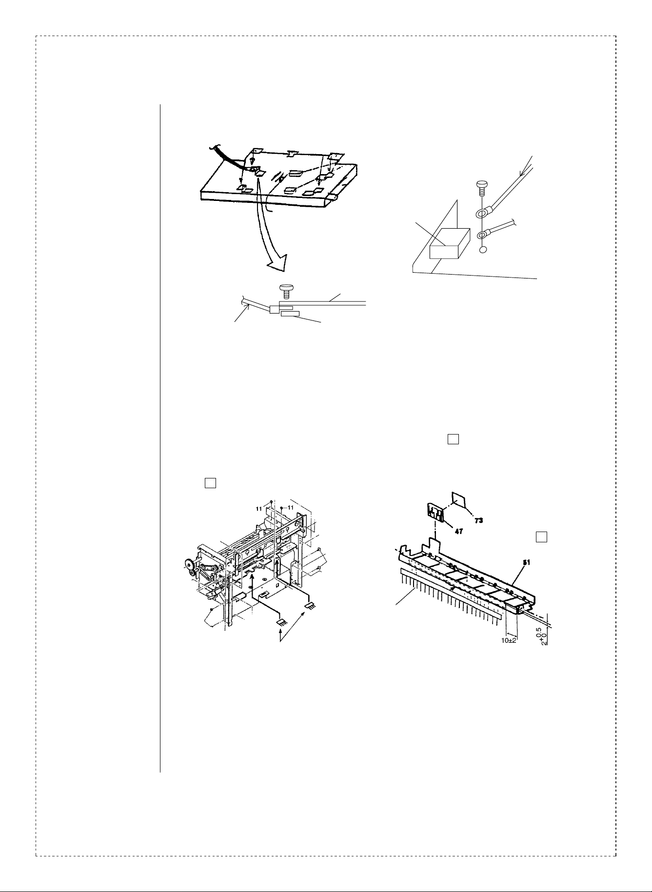
(7) An ground wire has been added in the operation panel (LCD PWB FG) as a measure
to improve noise. (This measure has been carried out only on the 200 V line.)
LCD PWB FG
Main SW
LCD PWB FG
Lower LCD case surface
OPE
Fixing plate
From the start of 1994 Oct ober production.
(8) The parts additions and discontinuances listed below have been carried out since
the start of mass production after the parts guide was compiled, and are hereby
reported.
51
P/G
Discontinued part FIN drop sheets (Qty: 2) P/G -131
47
Added discharge brush.
PBRSR0083FCZZ
Added discharge brush.
PBRSR0141FCZZ
Sub PG upper unit
51
-51
From the start of mass production.
3/7
Page 4

(9) The fixing screws used to attach the mai n drive unit and the DR drive unit to the
frame have been changed to improve operationability.
9
P/G -9 M4 x 12 → M4 x 14
From the start of 1994 Oct ober production.
(10) The parts listed below have been added as a measure to reduce noise.
(This change has been carried out only on the 200 V series.)
Front side
Mesh wire
(QCNW-0138FCZZ)
Standard
Standard
P/G No. gasket added
to the FIN joint plate
51
Gasket
Finished tray
View from the
paper side
P/G No. mesh wire added to the
finished shift unit
Shift unit
From the start of 1994 Oct ober production.
(11) Sheets have been added to the gate section to improve stacking performance.
Added FIN paper
discharge sheet
4/7
From the start of mass production.
Page 5

(12) A ferrite core has been added to the finisher main PWB fixing plate unit in order to
comply with the CE mark standards. (This change has been carried out on the 200 V
series only.)
P/G No.
Added ferrite core
55
From the start of 1995 April production.
(13) A laser warning label has been added to the front cabinet and to the finisher
section. This change has been carried out only on machines bound for SUK.
Laser warning label
P/G No.
Sub paper guide upper
51
Laser warning label
P/G No. Front exterior left
48
Sub paper guide upper
Laser warning label
P/G No. Front exterior right
1
From the start of 1995 April production.
Laser
warning
label
5/7
Page 6

(14) An additional manual has been added to supplement the explanation contents of
the operation manual. This change has been carried out only on machines bound
for SUK.
From the start of 1995 February production.
(15) Parts in one of the sections of the shield box have been assembled and the
assembled unit is being offered as a service part. Furthermore, a carved
grounding mark has been added, and the former grounding mark label has
been discontinued.
P/G No. XBPSD40P08KSO.
P/G No. NSFTZ2116FCZZ.
P/G No. LBSHZ0251FCZZ. Assembled
P/G No. LPLTM4733FCZZ.
P/G No. PBOX-0100FCZZ.
P/G No. LHLDW2106SCZZ.
35 -3
35 -8
35 -9
35 -10
35 -11
35 -21
From the start of 1995 May production.
Ref.
Model
No.
(2)
(3) All
AR-5040
(4)
name
Version P/G No.
100V
series
200V
series
200V
series
12 -28 PCOVP1248FCZZ
68 -27
68
68 -59
35 -17
68 -901
12 — RCORF0012FCZZ AH Ferrite core
Current parts New parts
Parts code Parts code
PCOVP1321FCZZ BA
PCOVP1322FCZZ BB
VCKYTV1EF104Z
(Q’ty: 86) (Q’ty: 88)
— VHI74F00SJ/-1
VHI74F74SJ/-1
(Q’ty: 1) (Q’ty: 2)
CPWBN1031FC51 CPWBN1031FC52 EZ ICU PWB 1
Price
Parts name
rank
CCD cover
AA Capacitor
IC [ IC70 ]
AE
IC
CBOX-0100FC31
Effec-
Inter-
tive
change-
time
ability
1st lot
’94/10
1st lot
’94/12
1st lot
’94/10
Note
3
6
6
6/7
(5)
(6)
(7)
(8) All
100V
series
SEEG
U.K.
Australia
200V
series
49 -52
49 -53 PSHEP3620FCZZ PSHEP3735FCZZ AF Upper S T sheet B
35 -16 LFIX-0084FCZZ LFIX-0016FCZZ AD AC cord holder —
2
51 -131
51
47 PBRSR0141FCZZ AF Discharge brush Q’ty: 2
PSHEP3622FCZZ PSHEZ3734FCZZ AG ST cover sheet
— QCNW-0139FCZZ AN LCD PWB FG
PSHEP3618FCZZ
(Q’ty: 2)
—
(Discontinuance) — FIN drop sheets
PBRSR0083FCZZ AH Discharge brush
1st lot
’94/12
1st lot
’94/10
See
text
3
6
—
6
Page 7

Ref.
No.
(9)
(10)
Model
name
Version P/G No.
9-9
All
51
200V
series
50 QCNW-0138FCZZ AN Mesh wire
Current parts New parts
Parts code Parts code
XBBSD40P12000 XBBSD40P14000 AA Screw(M4X14)
PGSK-0006FCZZ AV Gasket
Price
Parts name
rank
Effec-
tive
time
1st lot
’94/10
Inter-
change-
ability
3 Q’ty: 6
Note
(11) All 54 PSHEP3852FCZZ AC
200V
(12)
AR-5040
(13)
(14) 74 TCADZ1216FCZZ AP
(15) All
<Interchange>
1. Interc ha ng ea bl e. 4. N ot i nt er ch an ge ab l e.
2. Current type can be used in place of new type.
New type cannot be used in place of current type.
3. Current type cannot be used in place of new type.
New type can be used in place of current type.
Parts marked with “ ” is important for maintaining the safety of the set. Be sure to replace these parts with
s p eci fi e d on es fo r m ain ta in i ng t he s a fe ty an d pe rf o rma nc e o f th e s et .
55 RCORF1013LCZZ AN Ferrite core
series
1
48
SUK
only
51
35 CBOX-0100FC31 BT Shield box unit
35 -12 TLAB-4681CCZZ (Discontinuance) —
!
—
TCAUS0003GCZZ AB
5. Interchangeable if replaced with same types of
relate d parts in use .
6. Others .
FIN paper
discharge sheets
Laser warning
label
operation
manual
Grounding mark
label
1st lot Q’ty: 2
1st lot
’95/4
1st lot
’95/4
1st lot
’95/2
1st lot
’95/5
6
Q’ty: 3
7/7
 Loading...