

Page 1
E
AR-SP3
[5] AR-PG1
1. Electrical section
A. GDI/USB PWB
Personal
Personal
Computer
IEEE1284
DATA+
IC504
244
7SH08F
IC501
IC113 74HC14
7
PDATA0
74LS
245
IC601
GDI/USB PWB
7
/1284_EN
PDATA0
ASIC
IC10
MCU PWB
/STB,/AUTOFD,/SLCTIN,/INIT
74LS
244A
74LS
IC602
REV
/STB,/AUTOFD,
/SLCTIN,/INIT
/USB_EN
/ACK,BUSY,PE,/FAULT,SLCT
244B
74LS
IC603
/ACK,BUSY,PE,
/FAULT,SLCT
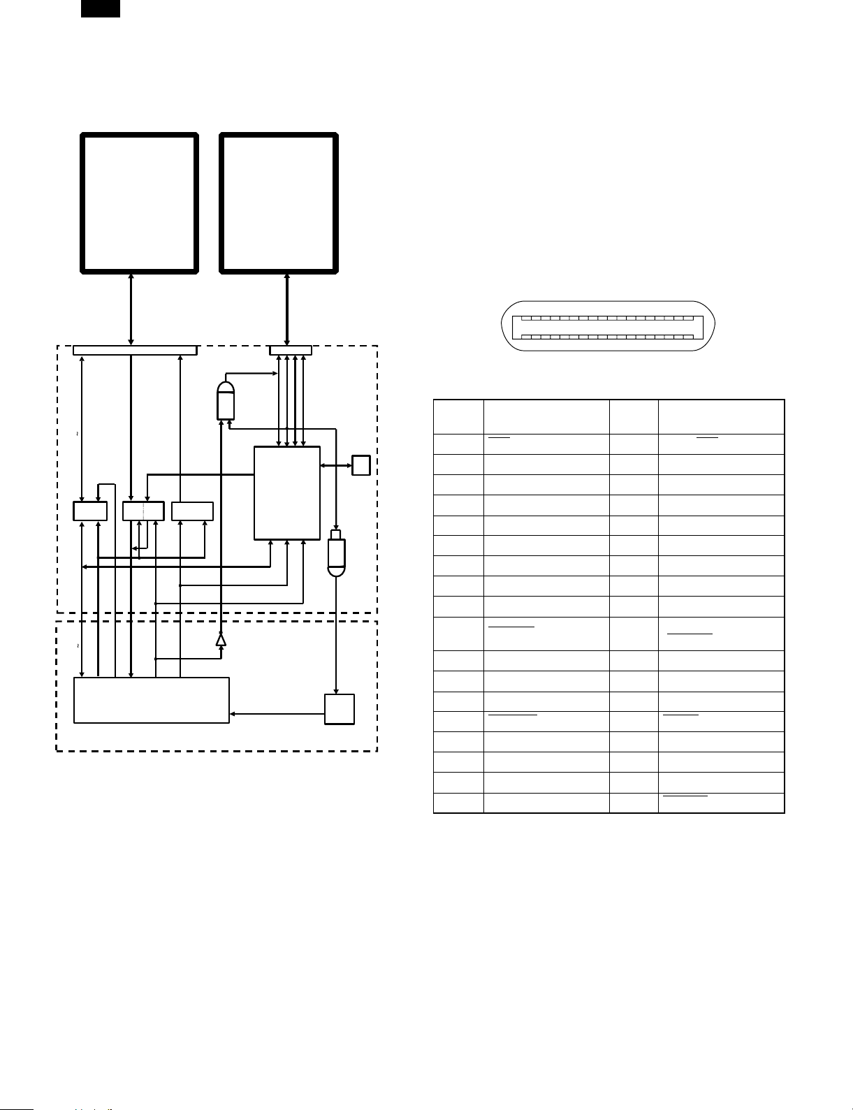
The GDI/USB PWB has two circuits; one for transmitting and receiving
IEEE1284 signals and the other for transmitting and receiving USB signals and converting USB signals into IEEE1284 signals.
IC601, 602 and 603 are connected between IEEE1284 an ASIC to convert signals.
IC501 transmits and receives USB signals and converts USB signals
into IEEE1284 signals.
IC502 stores various setup data necessary for USB operation of IC501.
IC503 informs the CPU of connection of USB. It is connected with PC
via a USB cable. When 5V is inputted from PC to the IC’s input pin,
the output pin (signal name: USB-IN) is driven to HIGH to inform the
CPU of connection of USB.
IC504 detects connection with PC via a USB cable, supplies power to
the USB port signal line (signal name: DATA+) to enable USB communication.
When USB is connected, the CPU enables USB and disables
IEEE1284.
(When USB is enabled, IE1284 is disabled.)
Computer
USB
DATA -
GND
DATA +
5V
USS-725
RESET/DISABL
IC9
IC503
5V
7SH08F
USB-IN
CPU
EEPR
OM
IC502
2. Interface
A. PARALLEL INTERFACE
This printer uses a bi-directional parallel interface. Use the supplied interface cable.
Connector
36-pin DDK 57LE-40360-730B (D29) female connector or equivalent
connector
Cable
Shielded type bi-directional parallel interface
For best results,, use a printer interface cable which is IEEE1284 compliant.
Pin configuration
The pin numbers and signal names are listed in the following table.
18
36 19
Pin
No.
Signal name
1 STB 19 GND (STB RET)
2 DATA1 20 GND (DATA1 RET)
3 DATA2 21 GND (DATA2 RET)
4 DATA3 22 GND (DATA3 RET)
5 DATA4 23 GND (DATA4 RET)
6 DATA5 24 GND (DATA5 RET)
7 DATA6 25 GND (DATA6 RET)
8 DATA7 26 GND (DATA7 RET)
9 DATA8 27 GND (DATA8 RET)
10 ACKNLG 28
11 BUSY 29 GND (BUSY RET)
12 PE (Paper End) 30 GND (PE RET)
13 SLTC 31 INPRM
14 AUTO LF 32 FAULT
15 (NC) 33 (NC)
16 GND (0 V) 34 (NC)
17 FG 35 +5 V
18 +5 V 36 SLTC IN
Pin
No.
1
Signal name
GND
(ACKNLG RET)
5 – 1
Page 2
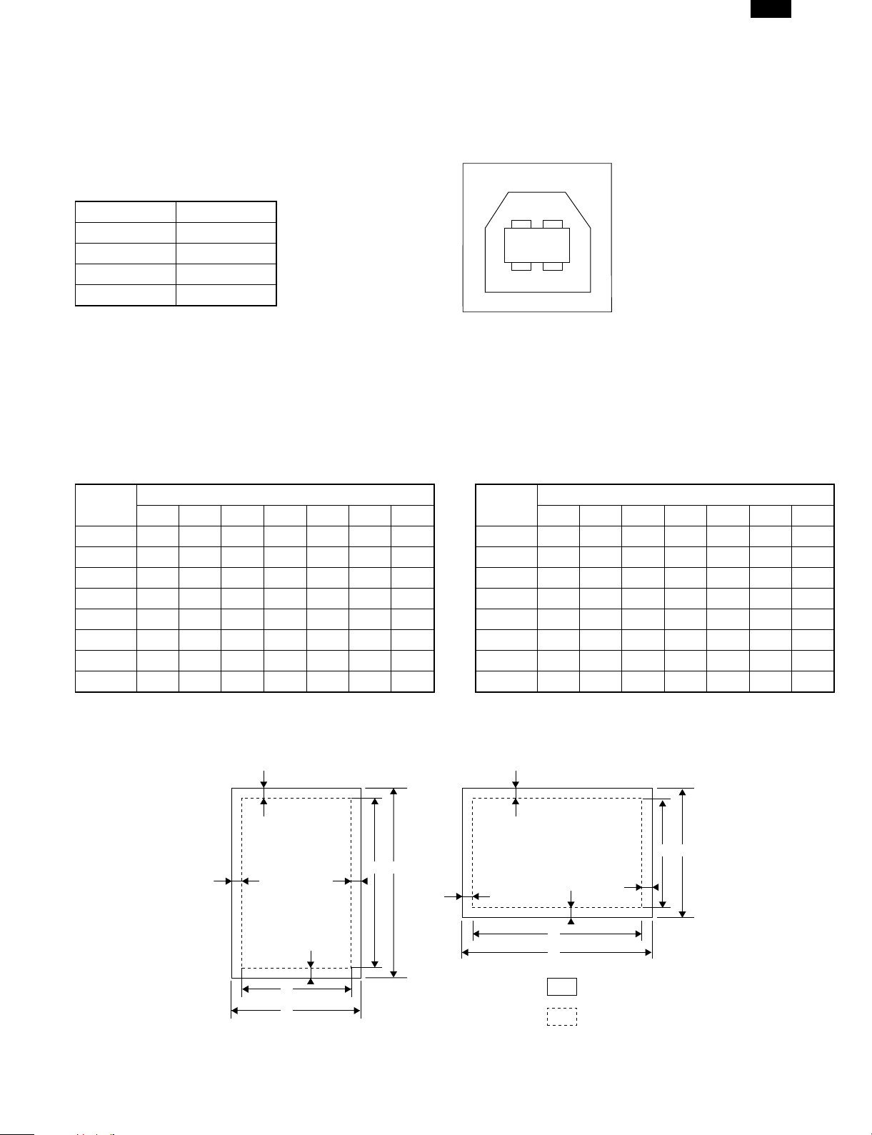
B. USB INTERFACE
Connector
4-pin DDK DUSB-BRA42-T11
Type-B connector
Cable
Shielded twisted pair cable
(2 m (6 feet) Max.: high-speed transmission equivalent)
Pin configuration
The pin numbers and signal names are listed in the following table.
Pin No. Signal name
1 +5V
2 – DATA
3 +DATA
4 GND
3. Print Area
The print area of this printer is shown below.
A. 600 dpi
2
34
1
B. 300 dpi
AR-SP3
Paper
size
Letter 5100 4900 6600 6400 100 100 100
Legal 5100 4900 8400 8200 100 100 100
Invoice 3300 3100 5100 4900 100 100 100
A4 4960 4760 7014 6814 100 100 100
A5 3508 3308 4960 4760 100 100 100
B5 4298 4098 6070 5870 100 100 100
Folio 5100 4900 7800 7600 100 100 100
Foolscap 5100 4900 7440 7240 100 100 100
ABCDEFG
E
Dots
Portrait
E
D C
F
Paper
size
Letter 2550 2450 3300 3200 50 50 50
Legal 2550 2450 4200 4100 50 50 50
Invoice 1650 1550 2550 2450 50 50 50
A4 2480 2380 3507 3407 50 50 50
A5 1754 1654 2480 2380 50 50 50
B5 2149 2049 3035 2935 50 50 50
Folio 2550 2450 3900 3800 50 50 50
Foolscap 2550 2450 3720 3620 50 50 50
E
ABCDEFG
Landscape
E
G
F
Dots
B A
D
G
B
A
5 – 2
C
Paper size
Print area
Page 3

IEEE1284 CON
47u 16V
100J 1/2W
S GND
F GND
S GND
DATA 8
DATA 7
DATA 6
DATA 5
DATA 4
DATA 3
DATA 2
DATA 1
AR-SP3
4. Circuit diagram
(2-A3)
(2-A3)
PARAAD7
PARAAD6
(2-A3)
(2-A3)
PARAAD4
PARAAD5
(2-A2)
(2-A2)
PARAAD2
PARAAD3
11
(2-A2)
PARAAD1
(2-A2)
PARAAD0
E
D
C
B
44
36
35
34
33
32
31
30
VCC
(NC)
GND29GND28GND27GND26GND25GND24GND23GND22GND21GND20GND19GND
S GND
/FAULT
/SLCTIN
/INPRIM
E
D
C
B
IEEE1284 CON
DATA 8
DATA 7
DATA 6
DATA 5
DATA 4
DATA 3
DATA 2
DATA 1
/DSTB
CN501
1
1.2kJ
R625
1.2kJ
R624
1.2kJ
R623
1.2kJ
R622
1.2kJ
R621
1.2kJ
R620
1.2kJ
R619
1.2kJ
R618
5V1
5V1
(2-B4)
5V1
IC601
5V1
22000p
C613
47u 16V
C501
SBO-02SAN
L501
9
8
7
6
5
4
3
2
2
1
2
1
2
1
2
1
22J
22J
22J
22J
22J
22J
22J
R606
R604
R603
R602
R601
A1
B1
R608
R607
R605
100p
C608
100p
C607
100p
C606
100p
C605
100p
C604
100p
C603
100p
C602
100p
C601
1
19G9A88A77A66A55A44A33A22
C619
DIR
74LS245
11B812B713B614B515B416B317B218
D604
D603
D602
D601
0.1u
(NC)14/AUTOLF13SLCT12PE11BUSY10/ACK
16
15
3
DAP202K
3
DAP202K
3
DAP202K
3
5V1
DAP202K
22J
SHIELD
VCC17F GND
S GND
18
R629
R628
R627
R626
33
3.3kJ
R630
5V1
5V1
F.G
100J 1/2W
R501
1.2kJ
1.2kJ
1.2kJ
1.2kJ
2
3
1
D606
DAP202K
2
3
1
D605
DAP202K
22J
22J
22J
22J
R610
R609
R612
R611
C612
560p
33p
C611
33p
C610
1000p
C609
0.1u
5V1
IC602
C621
(2-A2)
(2-A2)
(2-A3)
(2-A2)
/INIT
/AUTOFD
/STB
/SLCTIN
2A4152A3132A2112A181A461A341A221A1
2Y452Y372Y292Y1
1Y4141Y3161Y2181Y1
3
12
(2-D3)
/USB-EN
192G11G17
74LS244
22J
22J
R614
R613
IC603
1A461A341A221A1
8
5V1
5V1
22
2
3
1
D609
2
DAP202K
3
1
D608
2
DAP202K
3
1
DAP202K
D607
22J
22J
22J
R615
R617
R616
(2-A2)
(2-A2)
(2-A2)
(2-A2)
100p
C618
100p
100p
C617
100p
C616
C615
100p
C614
3
2Y452Y372Y292Y1121Y4141Y3161Y2181Y1
1G
2A4152A3132A2112A1
1
17
C620
(2-A2)
PE
BUSY
/ACK
SLCT
/FAULT
2G
74LS244
19
0.1u
A
GDI PWB(GDI SECTION)
CN502
PARAAD1
PARAAD0
PARAAD3
PARAAD2
PARAAD5
PARAAD4
987654321
PARAAD7
PARAAD6
10
A
(2-E3)
(2-B3)
(2-B1)
USB-ON
USB-IN
3.3V
USB-ON
/USB-EN
/1284-EN
USB-IN
/GDI-IN
SLCT
/FAULT
PE
BUSY
/ACK
/STB
/AUTOFD
/SLCTIN
/INIT
/REV
313029282726252423222120191817161514131211
31FE-BT-VK-N
5 – 3
Page 4

AR-SP3
R511TC7SH08FU
C520
3
11
E
D
C
10kJ
0.1u
B
22
0.1u
5V2
(2-D3)
3.3V5V2
0.1u
C511
0.1u
C510
5V2
2
1
5
IC503A
4
USB-IN 5V-USB
(1-A4)
(1-A4)
USB-ON
4
R508
2
24C16
0.1u
(2-D3)
5V-USB
C519 24J
0.1u
R510
R509
0.1u
3
TC7SH08FU
33
10kJ
10kJ
1.5kJ
R507
(1-A4)
/USB-EN
3.3V
3.3V
C513
48
47
45
44
43
VDD
GND
TEST046TEST1
SIXTEEN_BIT
DISABLE_1284
49
RESET
50
SELF_PWRD
51
SDA0
52
SCL
53
PDATA17
54
PCONTROL4
55
PCONTROL3
56
GND
57
VDD
58
PDATA7
59
VDD5
60
PDATA16
61
PCONTROL2
62
PCONTROL1
63
PDATA6
64
PDATA15
IC501
3.3V
1
5V2
PCONTROL0
PERROR
PDATA55GND
2
3
PDATA14
VDD5
6
4
0.1u
C505
SHIELD
CN503
5V-USB
(2-E3,C1)
24J
R506
R505
C515
0.1u
41
40
42
39
DPLS
DMNS
PLL_VSS
PLL_VDD
PDATA416PDATA3
nFAULT
VDD
nSELECTIN
9
8
7
10
0.1u
C506
GND3D+2D-15V
4
24J
38
VDD
PDATA13
11
5V2
C518
0.1u
37
CLK_HI
GND
12
C507
USB-B CONNECTOR
0.1u
C517
35
36
GND
CLK_LO
SCAN_EN
PDATA0
PDATA10
PDATA1
VDD5
PDATA11
PDATA2
nAUTOFD
PDATA12
nSTROBE
VDD5
14
13
0.1u
X501
C516
34
SUSPEND
PLH
HLH
nACK
nINIT
VDD
GND
BUSY
SELECT
15
15p
12MHz
15p
3.3V
C514
33
nUSB_RESET
32
31
30
29
28
27
26
25
24
23
22
21
20
19
18
17
F.G
USS-725
44
E
1
5
3.3V
IC504A
D
4
3A22A11
A0
GND
0.1u
Vcc7/WC6SCK5SDA
IC502
C512
8
5V25V2
5V2
1kJ
R503
1kJ
SBO-02SAN
R502
C509
C508
5V2 3.3V
3.3V
0.1u
C622
1.5u 16V
C502
L503
SBO-02SAN
3.3V
(1-A4)
0.1u
C504
1.5u 16V
C503
C
5V2
L502
5V1
(1-B4)
B
A
GDI PWB (USB SECTION)
PARAAD6
PARAAD7
(1-C1)
(1-C1)
PE
(1-C2)
PARAAD5
(1-C1)
/SLCTIN
(1-B3)
PARAAD4
/FAULT
(1-C2)
(1-C1)
5 – 4
/STB
(1-B3)
SLCT
(1-C2)
PARAAD3
(1-C1)
/AUTOFD
BUSY
(1-C2)
(1-B3)
/INIT
PARAAD2
(1-B3)
(1-C1)
/ACK
(1-C2)
PARAAD0
PARAAD1
(1-C1)
(1-C1)
A
 Loading...