

Page 1
AR-DE7
AR-CS3
CODE: 00ZARDE7//A1E
DIGITAL COPIER
OPTIONS
AR-DE7
MODEL AR-CS3
1-step paper
feed desk
Paper feed
module
AR-DE7
CONTENTS
[Note]
This Service Manual describes only the differences from 00ZARDE2//A1E.
The items which are not described in this Manual are common with the
00ZARDE2//A1E.
[ 1 ] PRODUCT OUTLINE . . . . . . . . . . . . . . . . . . . . . . . . . . . . . . . . . 1-1
[ 2 ] SPECIFICATIONS . . . . . . . . . . . . . . . . . . . . . . . . . . . . . . . . . . . 1-1
[ 3 ] UNPACKING AND INSTALLATION . . . . . . . . . . . . . . . . . . . . . 1-1
[ 4 ] EXTERNAL VIEW AND INTERNAL STRUCTURE . . . . . . . . . . 4-1
[ 5 ] DISASSEMBLY AND ASSEMBLY . . . . . . . . . . . . . . . . . . . . . . 5-1
[ 6 ] ADJUSTMENTS . . . . . . . . . . . . . . . . . . . . . . . . . . . . . . . . . . . . 6-1
[ 7 ] MAINTENANCE . . . . . . . . . . . . . . . . . . . . . . . . . . . . . . . . . . . . . 7-1
[ 8 ] TROUBLESHOOTING . . . . . . . . . . . . . . . . . . . . . . . . . . . . . . . . 8-1
[ 9 ] ELECTRICAL SECTION . . . . . . . . . . . . . . . . . . . . . . . . . . . . . . 9-1
PARTS GUIDE
This document has been published to be used
for after sales service only.
The contents are subject to change without notice.
Page 2
AR-DE7
List of different points between the AR-DE7/CS3 and the AR-DD1/DE1/CS1
No.
Page Item Content Change Remark
AR-DD1/DE1/CS1 AR-DE7/CS3
1 1-1 [2]-9 Paper transport speed:
170mm/s – 306mm/s Changed to 432mm/s
2 1-1 [2]-10 Paper feed speed:
33 sheets/min Changed to 50 sheets/min
3 1-1 [2]-19 Power consumption:
24W (MAX) Changed to 36W (MAX)
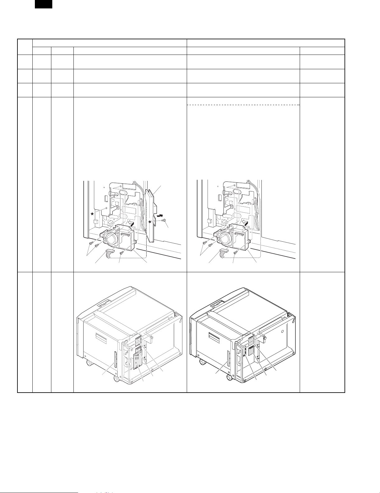
4 3-5 [3]-2-C 2. Install the lift up unit.
Remove the fixing screw (section ★) of the desk
PWB mounting plate, and open the desk PWB
mounting plate.
Attach the lift up unit to the rear frame of the
desk and slide it to the left.
Fix the lift up unit with the fixing screws A (3
pcs.) and connect the desk PWB connector to
Change Desk PWB
2. Install the lift up unit.
Attach the lift up unit to the rear frame of the
desk and slide it to the left.
Fix the lift up unit with the fixing screws A (3
pcs.) and connect the desk PWB connector to
the lift up unit connector.
the lift up unit connector.
Return the desk PWB mounting plate to the
original position, and fix it with the fixing screw
(section ★).
Desk PWB mounting
plate
mounting plate
abolished.
(Changed to the
duplex PWB.)
Desk mounting
plate fixing screw
Fixing screw A
Desk PWB connector Fixing screw A Lift up unit
Fixing screw A
Desk PWB connector Fixing screw A Lift up unit
5 4-1 [4]-2 1) PWB Illustration changed Desk main PWB
installing position
changed.
(Changed to the
duplex PWB)
2
1
3
4
2
1
3
4
8/6/1999 – 1 –
Page 3
AR-DE7
No.
Page Item Content Change Remark
AR-DD1/DE1/CS1 AR-DE7/CS3
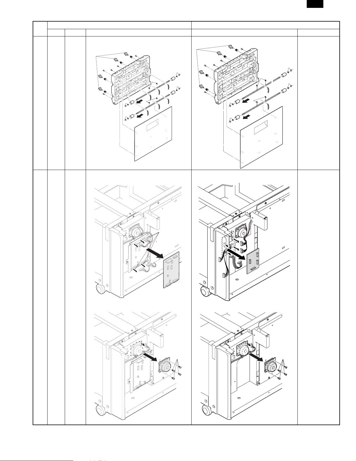
6 5-3 [5]-2-C Paper transfer idle roller Illustration changed
1)
1)
1)
1)
1)
1)
2)
2)
2)
5)
6)
2)
2)
6)
4)
2)
5)
4)
6)
2)
4)
4)
4)
4)
1)
1)
1)
1)
2)
2)
2)
5)
6)
2)
2)
2)
5)
6)
6)
2)
4)
4)
7 5-3 [5]-3 Desk control PWB, Paper transfer motor Illustration changed Changed to the
duplex PWB.
2)
1)
1)
1)
3)
1)
Desk main PWB
abolished.
2)
1)
2)
1)
– 2 – 8/6/1999
Page 4

AR-DE7
No.
Page Item Content Change Remark
AR-DD1/DE1/CS1 AR-DE7/CS3
8 5-4 [5]-4 Drive unit Illustration changed Desk main PWB
added.
2)
5)
4)
1)
5)
3)
3)
3)
4)
3)
3)
3)
9 5-4 [5]-5 Lift up unit Illustration changed Desk main PWB
added.
7)
2)
5)
4)
6)
6)
1)
3)
3)
4)
10 7-2 [7]-2 Paper transport secttion Illustration changed
2
7)
6)
6)
5)
3)
3)
2
2
2
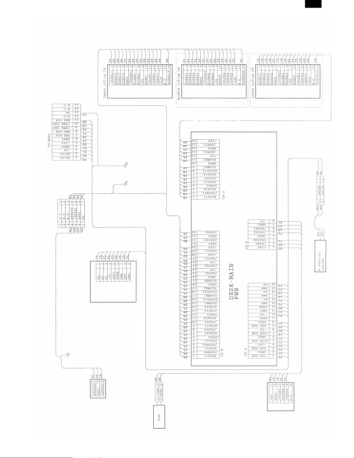
11 9-1 [9]-1 Actual wiring diagram Change Refer to the
attached page.
12 9-3 [9]-3 Main PWB block diagram Change Refer to the
attached page.
13 9-4 [9]-4 Parts arrangement Changed to the duplex PWB. Refer to the
attached page.
8/6/1999 – 3 –
Page 5
AR-DE7
AR-DE7 option
Paper feed system harness 1 2-cassette W
AR-DE7 no provision
AR-DE7 no provision
(Japan spec. only)
PPD interface harness
1. Actual wiring diagram
[9] ELECTRICAL SECTION
Desk main motor
Top stage paper exit sensor
Copier interface harness H W
(Japan spec.)
Copier interface harness 100
W (EX spec.)
Dehumidifying heater
Transport sensor harness W
PFD PWB UN
Transport roller clutch
9 – 1 8/6/1999
Page 6

AR-DE7
+24V
+10V
(24vm)
24V monitor
P36
P63
(DLUM3)
Lift up motor
IC05
driver
P34,P35
P62
(DLUM2)
Lift up motor
Output
section
IC04
driver
Output
P32,P33
section (1)
P64
(DLUM1)
Lift up motor
(2)
IC03
driver
P30,P31
IC08
(DPFC)
paper feed
Paper feed clutch
C P U
TXD,P52
(DTRC)
Transport clutch
solenoid (DPFS)
IC01
P10~P15,P17
driver
X1,X2
Output
section
Paper empty sensor
(DLUD)
(DPED)
Top cassette
remaining paper
Upper limit sensor
(1)
P40~P42,
P70,P72
(DPCD)
(DCSPD)
Door open/close
Paper exit sensor
quantity detection
P21~P27
sensor (DDCPSW)
(2)
Input
section
IC06
driver
IC02
RES,RXD,P46
IC09
X1
(8.00MHz)
Input
section
IC11, IC12
8-CHANNEL
(1)
MULTI
PLEXER
section
Communication
(DCSS)
Tray size detection
stage tray paper
remaining quantity
Middle stage, lower
sensor (DCSPD2, 3)
+5V
IC07
driver
+5V
driver
IC10
amplifier
operation
PWB
Copier main
Transport
motor (DM)
3. Main PWB blook diagram
8/6/1999 9 – 2
Motor drive section
Page 7

4. Parts arrangement
AR-DE7
CN-C
B16B-PHDSS-B
DCSS31
1
/FOUND3
2
DCSS32
3
DPED3
4
5
DCSS33
/DLUD3
6
DCSS34
7
DCSPD32
8
DLUMA3
9
GND2
10
DLUMB3
11
12
+5V
/DPFS3
13
GND2
14
/DPFC3
15
+24V
16
0EUPWB0406J31,41,51only
CN-D
B34B-PHDSS-B
1
DCSS11
2
/FOUND1
DCSS21
3
4
/FOUND2
DCSS12
5
6
DPED2
DCSS22
7
8
/DLUD2
DCSS13
9
10
/DLUD1
11
DCSS23
12
DPED1
DCSS14
13
14
DCSS24
DLUMA1
15
DCSPD12
16
DLUMB1
17
18 DCSPD22
DLUMA2
19
20
GND2
DLUMB2
21
22
GND2
23
/DPFS1
24
+5V
25
/DPFS2
26
+5V
27
/DPFC1
28
+24V
29 /DPFC2
30
+24V
31
GND2
32 DPPD5V
GND233
/DPOD1
34
CN-B
1
2
3
4
5
6
7
8
CN-A
1
2
3
4
5
6
7
8
9
10
11
12
13
14
15
16
17
18
19
20
B8B-PH-K-S
+24V
/DTRC
DDOPSW
GND2
/DPOD2
/DPOD3
GND2
+5V
B20B-PHDSS-B
TXD-DSK
GND2
RXD-DSK
+24V
/DTR-DSK
GND1
/DSR-DSK
+5V
RES-DSK
GND2
GND2
+5V
GND1
DMRE
DMU
HU
DMV
HV
DMW
HW
9 – 3 8/6/1999
Page 8

AR-DE7
Page 9

CAUTION FOR BATTERY REPLACEMENT
(Danish) ADVARSEL !
Lithiumbatteri – Eksplosionsfare ved fejlagtig håndtering.
Udskiftning må kun ske med batteri
af samme fabrikat og type.
Levér det brugte batteri tilbage til leverandoren.
(English) Caution !
Danger of explosion if battery is incorrectly replaced.
Replace only with the same or equivalent type
recommended by the manufacturer.
Dispose of used batteries according to manufacturer’s instructions.
(Finnish) VAROITUS
Paristo voi räjähtää, jos se on virheellisesti asennettu.
Vaihda paristo ainoastaan laitevalmistajan suosittelemaan
tyyppiin. Hävitä käytetty paristo valmistajan ohjeiden
mukaisesti.
(French) ATTENTION
Il y a danger d’explosion s’ il y a remplacement incorrect
de la batterie. Remplacer uniquement avec une batterie du
même type ou d’un type équivalent recommandé par
le constructeur.
Mettre au rebut les batteries usagées conformément aux
instructions du fabricant.
(Swedish) VARNING
Explosionsfara vid felaktigt batteribyte.
Använd samma batterityp eller en ekvivalent
typ som rekommenderas av apparattillverkaren.
Kassera använt batteri enligt fabrikantens
instruktion.
AR-DE7
Page 10

AR-DE7
All rights reserved.
Printed in Japan.
No part of this publication may be reproduced,
stored in a retrieval system, or transmitted,
in any form or by any means,
electronic; mechanical; photocopying; recording or otherwise
without prior written permission of the publisher.
SHARP CORPORATION
Digital Document Systems Group
Quality & Reliability Control Center
Yamatokoriyama, Nara 639-1186, Japan
1999 August Printed in Japan
 Loading...