

Page 1
CODE: 00ZARDE6//A1E
Digital copier
: Paper feed unit
AR-DE5
MODEL AR-DE6
CONTENTS
250-sheet paper
feed unit
500-sheet paper
feed unit
[1] PRODUCT OUTLINE . . . . . . . . . . . . . . . . . . . . . . . . . . . . . . . . . . . . 1
[2] SPECIFICATIONS . . . . . . . . . . . . . . . . . . . . . . . . . . . . . . . . . . . . . . 1
[3] UNPACKING AND INSTALLATION . . . . . . . . . . . . . . . . . . . . . . . . . 1
[4] EXTERNAL VIEW AND INTERNAL STRUCTURE . . . . . . . . . . . . . 6
[5] OPERATIONAL DESCRIPTION . . . . . . . . . . . . . . . . . . . . . . . . . . . . 7
[6] DISASSEMBLY AND ASSEMBLY . . . . . . . . . . . . . . . . . . . . . . . . . . 7
[7] MAINTENANCE . . . . . . . . . . . . . . . . . . . . . . . . . . . . . . . . . . . . . . . . 9
[8] ELECTRICAL SECTION . . . . . . . . . . . . . . . . . . . . . . . . . . . . . . . . . 10
Parts marked with "!" is important for maintaining the safety of the set. Be sure to replace these parts with specified
ones for maintaining the safety and performance of the set.
This document has been published to be used
SHARP CORPORATION
for after sales service only.
The contents are subject to change without notice.
Page 2
[1] PRODUCT OUTLINE
[3] UNP ACKING AND INSTALLATION
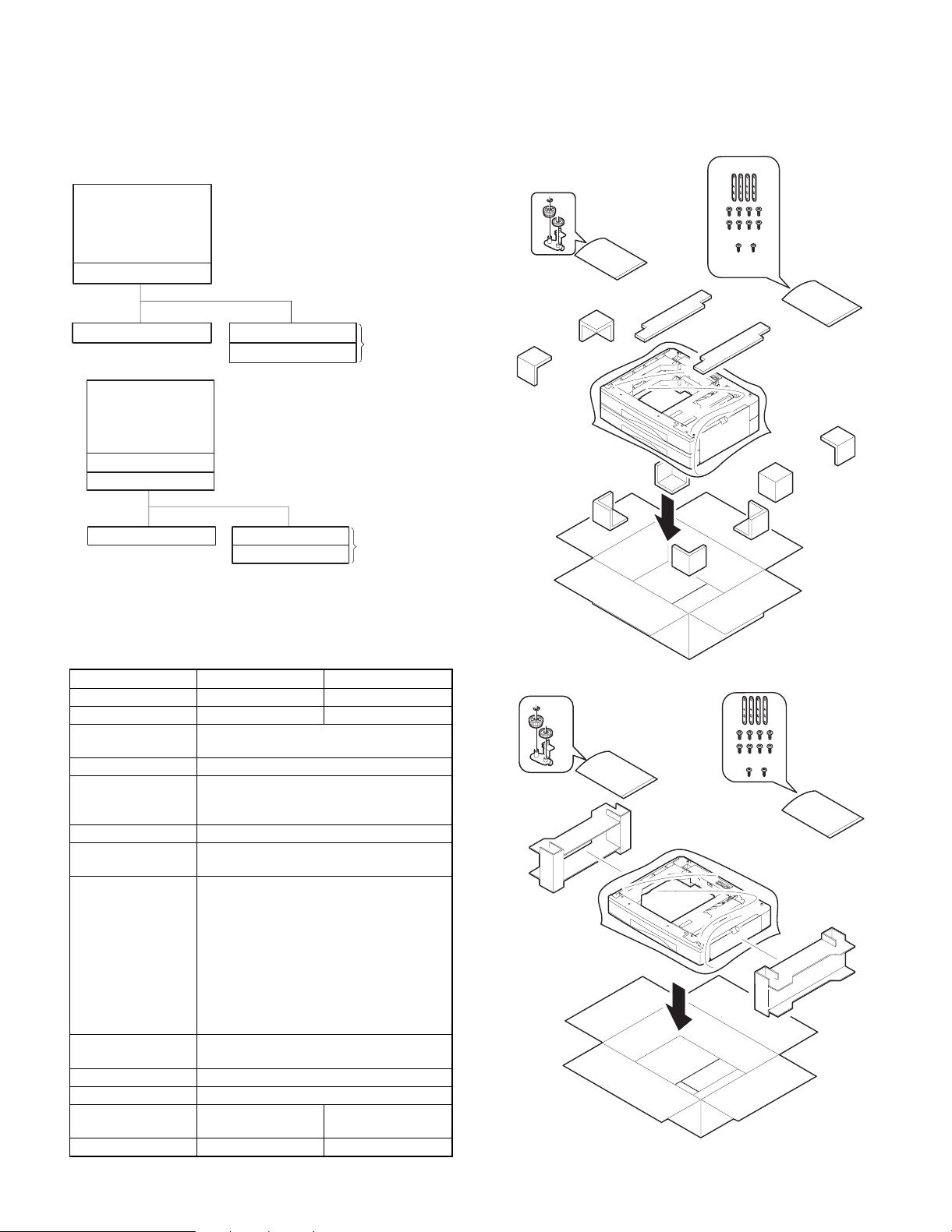
The 250-sheet paper feed unit and the 500-sheet paper feed unit are
the optional paper feed cassettes for the digital copier, and they are
the same structure as the 250-sheet cassette of the copier.
The combination of the copier and the paper feed cassette is as
shown below:
Copier
(1-Tray Model)
Standard cassette
250-sheet paper feed unit
Copier
(2-Tray Model)
Standard cassette
Standard cassette
250-sheet paper feed unit
250-sheet cassette
250-sheet cassette
250-sheet cassette
250-sheet cassette
500-sheet paper
feed unit
500-sheet paper
feed unit
1. Unpacking
(AR-DE6)
[2] SPECIFICATIONS
1. Paper feed unit
AR-DE5 AR-DE6
Paper feed step(s) 1-step 2-step
Paper feed capacity 250 sheets × 1 step 250 sheets × 2 steps
Size detection None (The paper size is set by the user
program.)
Paper feed detection Available
Paper feed size A3, B4, A4, A4R, B5, B5R, A5
11 × 17, 8.5 × 14, 8.5 × 13, 8.5 × 11
8.5 × 11R, 8.5 × 5.5, 8K, 16K, 16KR
Paper weight 56 ∼ 80g/m2, 15 ∼ 21lbs
Shipping size AB series: A3
Inch series: 11" × 17"
Size selection User operation (Size setting by the user
program)
Japan: A3, B4, A4, A4R, B5, B5R
Inch series: 11 × 17, 8.5 × 14, 8.5 × 11, 8.5
× 11R, 8.5 × 5.5
EX AB series: A3, B4, A4, A4R, A5
Inch series foolscap area: 11 × 17, 8.5 ×
14, 8.5 × 13, 8.5 × 11, 8.5 × 11R, 8.5 × 5.5
EX AB series foolscap area: A3, B4, A4,
A4R, A5, 8.5 × 13
Cassette
detachment
Heater Available only in Japan model
Power source Supplied from the machine.
External dimension 590 (W) × 571 (D) ×
Weight About 4.5 Kg About 9 Kg
Possible by the user
88 (H) mm
590 (W) × 571 (D) ×
173.5 (H) mm
(AR-DE5)
– 1 –
Page 3
2. Installation
Included parts
Part name Quantity
Screw (Fixing plate) 8
Screw 2
Fixing plate 4
Connection gear 1
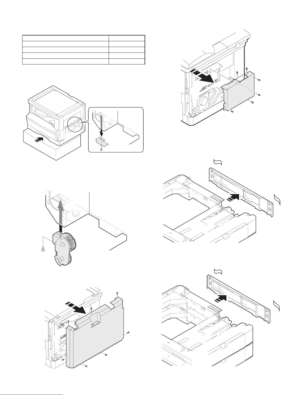
1) Remove the connection cover.
Put the copier on a desk, and remove the connection cover from the
bottom.
Remove the screws.
4) Remove the second cassette rear cover.
Remove the rear cover which is attached to the 250-sheet paper feed
unit.
2) Install the connection gear unit.
Install the connection gear unit to the place where the connection
cover was removed from.
3) Remove the machine rear cabinet and the shield plat.
Remove the screws.
Remove the rear cover (upper stage) from the 500-sheet paper feed
unit.
– 2 –
Page 4
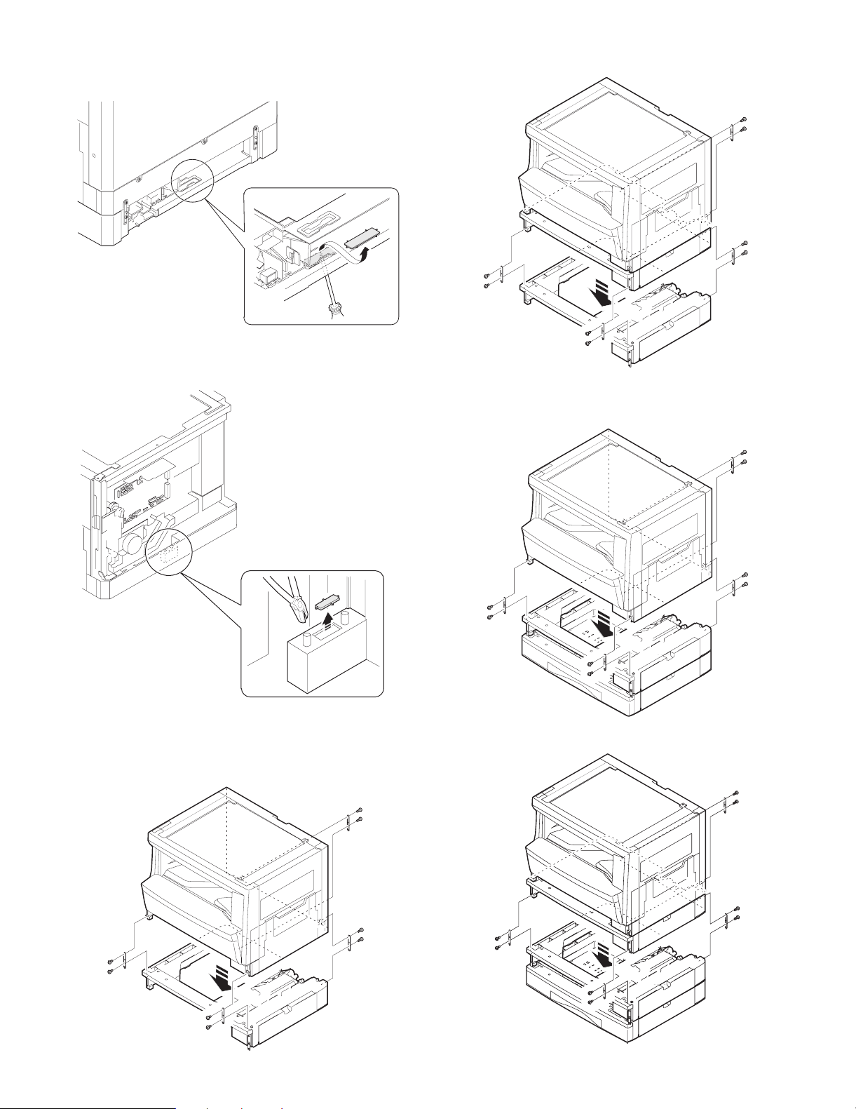
5) Open the connector hole in the bottom.
Use a screwdriver to push and open the hole.
6) Open the connector hole in the copier.
Use nippers to cut and open.
Copier (2-tray model) + 250-sheet paper feed unit
Put the copier to the 500-sheet paper feed unit, and fix it with fixing
plates and the fixing screws.
Copier (1-tray model) + 500-sheet paper feed unit
7) Install the copier onto the 250-sheet paper feed unit.
Put the copier on the 250-sheet paper feed unit, and fix with the fixing
plates and the screws.
Copier (1-tray model) + 250-sheet paper feed unit
Copier (2-tray model) + 500-sheet paper feed unit
– 3 –
Page 5
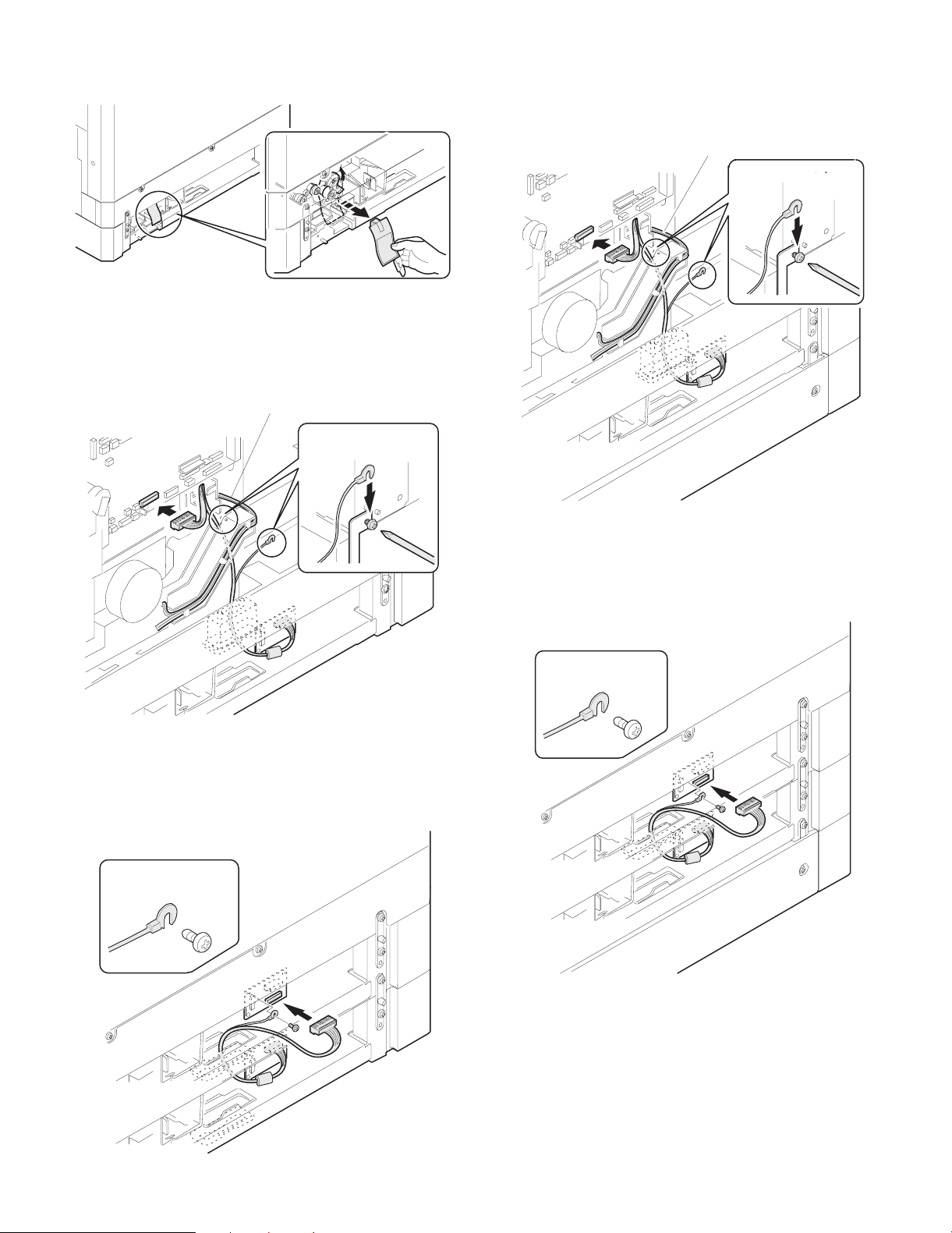
8) Remove the connection gear lock.
Remove the connection gear lock (with the red tug) after setting.
Copier (1-tray model) + 500-sheet paper feed unit
Set so that the optional interface harness connector is not brought
into contact with the primary side cable.
Fix the terminal section of the grounding wire together with the plate.
9) Set the connector.
Copier (1-tray model) + 250-sheet paper feed unit
Set so that the optional interface harness connector is not brought
into contact with the primary side cable.
Fix the terminal section of the grounding wire together with the plate.
Primary side cable
Be careful to the front
and the back sides.
Primary side cable
Be careful to the front
and the back sides.
Copier (2-tray model) + 500-sheet paper feed unit
Attach the optional interface harness to the interface PWB connector
on the second cassette side of the standard provision.
Fix the terminal section of the grounding wire together with the PWB
with the PWB fixing screw of the standard provision.
Copier (2-tray model) + 250-sheet paper feed unit
Attach the optional interface harness to the interface PWB connector
on the second cassette side of the standard provision.
Fix the terminal section of the grounding wire together with the PWB
with the PWB fixing screw of the standard provision.
Be careful to the front
and the back sides.
Be careful to the front
and the back sides.
– 4 –
Page 6

10) Remove the cassette packing fixtures.
Pull the cassette until it stops.
Turn and remove the packing fixture which is fixing the paper pres-
sure plate inside the cassette in the direction of arrow.
NOTE: To make the paper center shift adjustment and
the lead edge adjustment, insert the power plug
of the copier into the power outlet, turn on the
power switch, and perform the following
procedure.
14) Perform the center shift adjustment.
Set a document on the document glass and make a copy.
* If the image center is shifted, perform the following procedure.
1. Execute SIM 50-10 with the key operations on the copier.
11) Set the cassette side plate.
Hold the knob of the cassette side plate, slide it and set to the
position of the paper size to be used.
12) Install the cassette rear edge plate.
Install the cassette rear plate to the position of the paper size to be
used.
[Program key]
2. Enter the set value with the keys on the operation panel to perform the center shift adjustment, make a copy again, and check
that the center is not shifted.
C
0 5 0 1 0
• When the set value is increased, the image is shifted to the
rear side.
Center line of image
Center line
of paper
• When the set value is decreased, the image is shifted to the
front side.
Center line of image
Center line
of paper
13) Set the paper.
When setting the paper, do not exceed the height of the indication
label.
After completion of the adjustment, press the key to cancel the
mode.
CA
15) Perform the lead edge adjustment.
Set a document on the document glass, and make a copy.
1. Execute SIM 50-1 with the key operations on the copier.
[Program key]
2. Enter the set value with the keys on the operation panel and make
a copy to check that the lead edge is within the specified range.
C 1
0 5 0
0
• When the set value is increased, the copy image moves for-
ward.
• When the set value is decreased, the copy image moves back-
ward.
After completion of the adjustment, press the key to cancel the
mode.
CA
– 5 –
Page 7

[4] EXTERNAL VIEW AND INTERNAL STRUCTURE
1. External view
3
1
No. Name No. Name No. Name
1 Paper feed tray 2 2-step paper feed right cover 3 1-step paper feed right cover
2
2. Internal structure
11
3
1
2
1
6
5
4
9
10
8
Sensors and detectors
No. Code Name Type Function, operation Remark
1 DRS1 Door open/close sensor Photo transmission Detects door open/close.
2 PPD1 Paper entry sensor Photo transmission Detects paper transport.
3 CSS1 Paper empty sensor Photo transmission Detects paper presence/empty.
4 CASS1 Cassette detection SW Contact Detects cassette installation.
5 FSOL1 Transport solenoid DC solenoid Transports paper. (for clutch)
6 PSOL1 Paper feed solenoid DC solenoid Feeds paper. (For clutch)
7 PPD2 Paper entry sensor Photo transmission Detects paper transport. AR-DE6 only
8 CSS2 Paper empty sensor Photo transmission Detects paper in the cassette. AR-DE6 only
9 CASS2 Cassette detection SW Contact Detects cassette installation. AR-DE6 only
10 PSOL2 Paper feed solenoid DC solenoid Feeds paper. AR-DE6 only
11 PWB Interface PWB — — AR-DE6 only
7
– 6 –
Page 8

[5] OPERATIONAL DESCRIPTION
[6] DISASSEMBLY AND ASSE MBLY
1. Paper transport path
Transport roller
PF sensor
Copier
cassette
250-sheet paper
feed unit (upper)
250-sheet paper
feed unit (Lower)
Paper feed roller
2. Operational descriptions
The operations are controlled by the main body of the copier. the
paper feed roller (semi-circular roller) and the transport roller are
driven by the gear of the copier.
Paper is separated by the paper feed roller and the separation pawl,
and detected by the PF sensor, then transported to the Resist roller
by the transport roller.
To copier's PS
1. Rear cover
1
2
1
2. Paper feed unit section
5
5
Copier
4
3
1
2
250-sheet paper feed unit
Paper lead edge
No. Name Operation
1 Paper feed roller Picks up paper.
2 Separation pawl Prevents against double feed of
paper.
3 Transport roller Transports paper.
4 Paper entry sensor Detects paper transport.
5 Resist roller Makes synchronization between the
paper lead edge and the image lead
edge.
1
1
6
3
2
6
3
– 7 –
4
Page 9

3. Paper feed solenoid, transport solenoid
2
1
4. Transport roller gear section
5. Transport roller
2
1
A
B
1
6. Paper feed roller clutch
NOTE: When asembling the paper feed roller cluch, fit and insert
section A (D cut) into the shaft as shown in the figure.
A
2
2
1
1
3
– 8 –
Page 10

7. Paper feed roller
NOTE: Engage connection arm spring B with frame groove A and
connection arm groove C.
A
[7] MAINTENANCE
No. Name Work
item
1 Paper feed roller PA ass’y Cleaning F
2 Transport roller Cleaning F
When
service call
Remark
1
B
2
C
2
1
[Note] For disassembly and assembly of the paper feed roller and
the transport roller, refer to [6] DISASSEMBLY AND ASSEMBLY.
1
– 9 –
Page 11

1. BLOCK DIAGRAM 1/1
24V
5V2
D
5V1
[8] ELECTRICAL SECTION
12345678
D
– 10 –
Copier body
IC1
Y1
3
SELA
SELB
SELB
C
PSOL1
FSOL1
PSOL2
Y2
Data selector
IC2
Driver array
IC3
Data selector
5V1
24V
5V1
B
CASS1
PPD1
DRS1
CSS1
PSOL1
FSOL1
PSOL2
CASS2
PPD2
CSS2
5V2
5V2
5V2
5V2
5V2
24V
24V
24V
C
B
Multi step CS only
2nd/Multi step CS only
FSOL2
PSOL3
FSOL3
A
Y3
Lower connection CS
A
INTERFACE PWB
8 7 6 5 4
3
2 1
Page 12
D
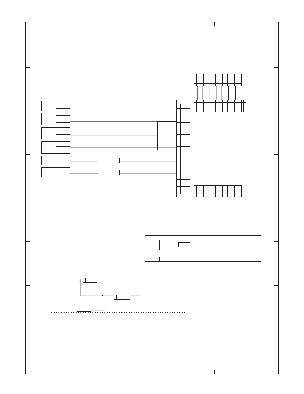
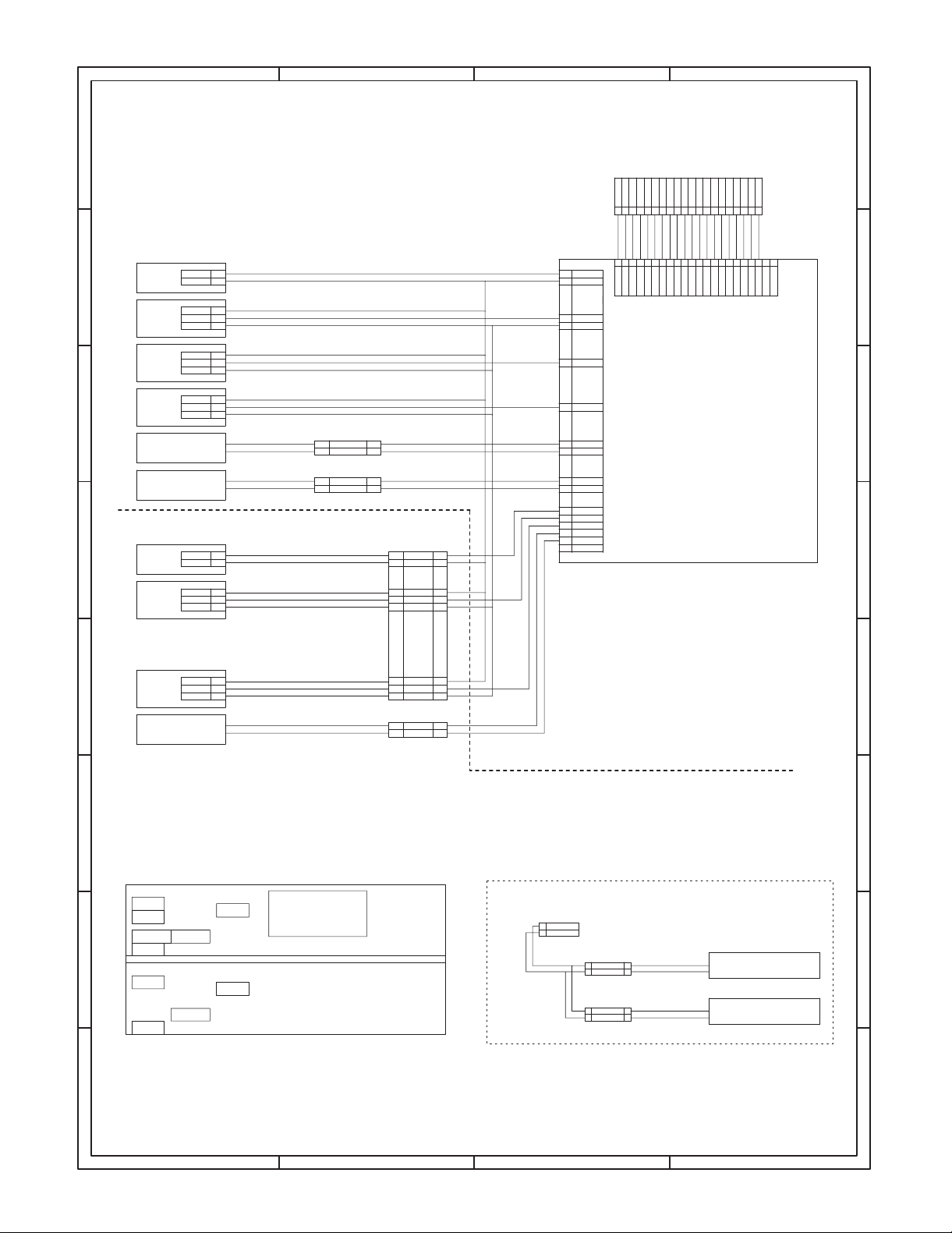
2. ACTUAL WIRING DIAGRAM
12345678
1. 2nd CS TYPE AR-DE5
175778-2
1
CASS1
LGND
LGND
PPD1
5V2
LGND
DRS1
5V2
LGND
CSS1
2
1
2
3
1
2
3
1
2
35V2
GY
DF3-3S-2C
GY
OR
DF3-3S-2C
GY
OR
DF3-3S-2C
GY
OR
RD
BL
RD
BL
1
2
1
2
CASS1
PPD1
DRS1
CSS1
PSOL1
FSOL1
24V1
/PSOL1
24V1
/FSOL1
C
BR
GY
BR
OR
PL
LB
SMP-02V-NCSMR-02V-N
1
2
SMP-02V-BCSMR-02V-B
1
2
RD
BL
RD
BL
B
PHDR-20VS
TO 2ND OR MAIN BODY
(UPPER UN)
PGND
PSOL2
FSOL1
FSOL2
24VY224V
PSOL1
2
5
3
1
7
46
RDRDPK
PK
PKPKPK
123 4 56789
CASS1
13
9
LGND
24V
24V
PSOL1
FSOL1
FSOL2
PSOL2
16
PPD1
5V2
11
14
15
DRS1
CSS1
CN-B
(B16B-PHDSS)
CS INTERFACE PWB
2ND CS
1
24V1
/PSOL1
2
3
24V1
4
/FSOL1
5
N.C.
N.C.
6
N.C.
7
N.C.
8
N.C.
10
N.C.
12
CN-C
24V
24V
FSOL3
FSOL2
PSOL2
PSOL3
2
5
3
1
7
6
Y1
LGND
SELA
PGND
LGND
PSOL39FSOL3
GYGYGYBRPLPLPLOROR
PK
21 22
PSOL3
FSOL3
10 16814
13
12
11
15
BR
GY
BR
1011 12 13 1415 1617 1819 20
PGND
PGND
LGND
LGND
CN-A
(B22B-PHDSS)
Y3
17
Y3Y2Y1
SELA
(B20B-PHDSS)
Y2
LGND
LGND
PGND13PGND
N.C.
N.C.
8
9
Y3
10 16
14
12
11
N.C.
SELA
17
A
5V2
SELB
5V120SELC
19
18
2 1
5V2
N.C.
N.C.
SELB
SELC
5V1
3
5V2
5V1
SELB
SELC
18415
19
20
ELP-02V
1
AC100N
2
AC100L
FOR LOWER OPTION CS
ELR-02V
1
AC100N
2
AC100L
D
TO 2ND OR MAIN BODY
(UPPER UN)
ELP-02V
WH
AC100N
1
BK
2
WH
BK
C
ELR-02V
1
2AC100L
2nd CS UNIT
PPD1
DRS1
FSOL1
CASS1
HEATER DH1
JAPAN ONLY
PSOL1
CSS1
UNIT REAR VIEW
PWB
8 7 6 5 4
B
A
– 11 –
Page 13
D
2. MULTI CS TYPE AR-DE6
12345678
C
B
PHDR-20VS
TO 2ND OR MAIN BODY
(UPPER UN)
A
UPPER UNIT
CASS1
CASS1
LGND
LGND
PPD1
PPD1
LGND
DRS1
DRS1
LGND
CSS1
CSS1
PSOL1
FSOL1
LOWER UNIT
CASS2
CASS2
LGND
LGND
PPD2
PPD2
5V2 3
175778-2
1
GY
2
DF3-3S-2C
GY
1
2
OR
35V2
DF3-3S-2C
GY
1
2
OR
35V2
DF3-3S-2C
GY
1
2
OR
35V2
RD
BL
RD
BL
175778-2
1
2
DF3-3S-2C
GY
1
2
OR
24VY224V
2
3
1
RDRDPK
BR
GY
BR
OR
PL
LB
1
2
1
2
SMP-02V-NCSMR-02V-N
1
24V1
2
/PSOL1
SMP-02V-BCSMR-02V-B
1
24V1
2
/FSOL1
SMR-08V-N SMP-08V-NC
BR
GY
GY
BR
OR
1
1
CASS2
2
2
LGND
3
3
LGND
4
4
PPD2
5
5
5V2
RD
BL
RD
BL
BR
BR
13
9
16
11
14
15
1
2
3
4
12
8
10
5
6
7
CASS1
LGND
PPD1
5V2
DRS1
CSS1
24V1
/PSOL1
24V1
/FSOL1
CASS2
PPD2
CSS2
24V1
/PSOL2
N.C.
123 4 56789
24V
24V
CN-B
(B16B-PHDSS)
PGND
FSOL1
PSOL1
46
PK
PSOL1
FSOL1
PSOL2
FSOL2
5
7
PKPKPK
FSOL2
PSOL2
Y1
LGND
PGND
LGND
PSOL39FSOL3
10 16814
13
12
11
BR
GY
PK
GYGYGYBRPLPLPLOROR
1011 12 13 1415 1617 1819 20
21 22
FSOL3
PSOL3
PGND
PGND
LGND
LGND
CN-A
(B22B-PHDSS)
CS INTERFACE PWB
MULTI CS
15
BR
SELA
Y3
17
SELAY3Y2Y15V1
5V2
SELB
5V120SELC
19
18
2 1
SELB
SELC
5V2
N.C.
N.C.
3
CSS2
PSOL2
PPD1
DRS1
FSOL1
CASS1
PPD2
CASS2
1
LGND
2
CSS2
3
5V2
MULTI CS UNIT
CSS1
PSOL1
CSS2
PSOL2
DF3-3S-2C
GY
OR
RD
BL
PWB
GY
6
LGND
LB
7
CSS2
OR
8
5V2
SMR-02V-N SMP-02V-NC
RD
1
24V1
BL
2
/PSOL2
UNIT REAR VIEW
UPPER UNIT
LOWER UNIT
6
7
8
1
2
LB
RD
BL
ELP-02V
1
2
TO 2ND OR MAIN BODY
(UPPER UN)
AC100N
AC100L
ELP-02V
WH
BK
1 AC100N
2
AC100L
ELR-02V
1
2
UPPER CS
HEATER DH2
LOWER CS
ELP-02V
1 AC100N
AC100L 2
2
ELR-02V
HEATER DH3
1
JAPAN ONLY
8 7 6 5 4
D
C
B
A
– 12 –
Page 14
12345678
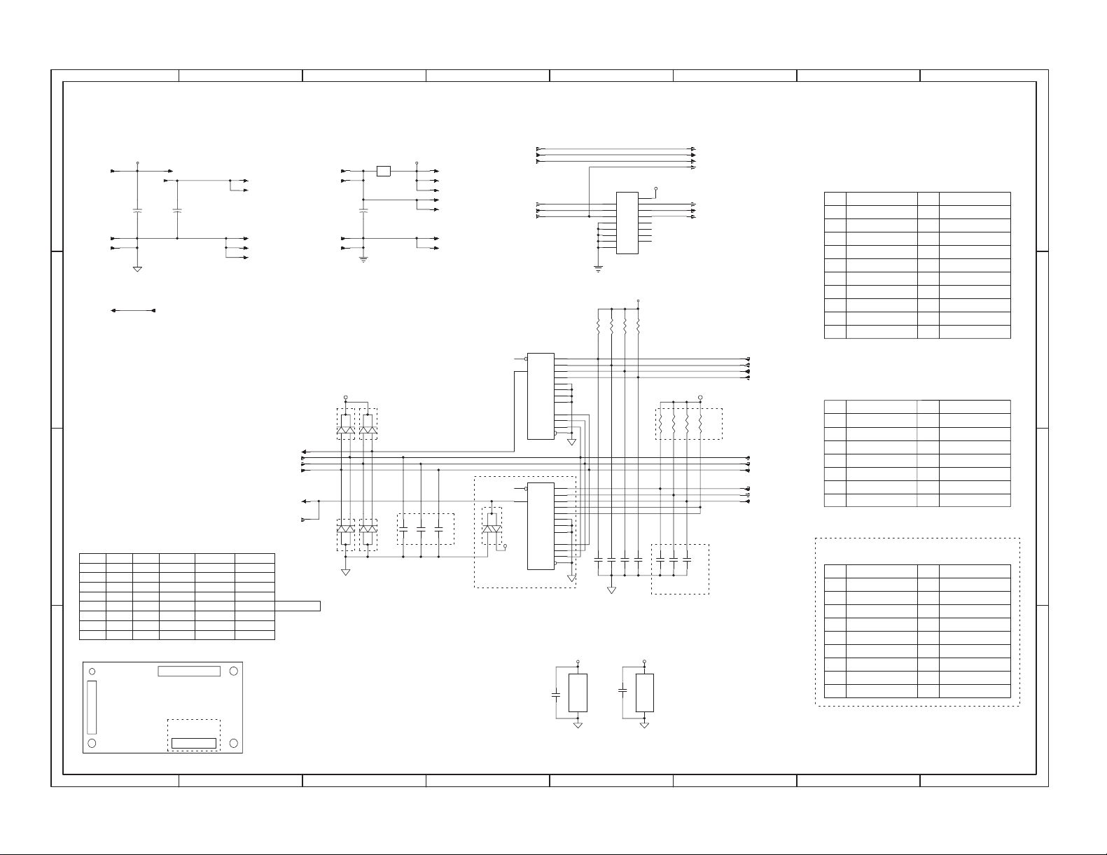
3. INTERFACE PWB CIRCUIT DIAGRAM 1/1
– 13 –
CNA-13,14
CNA-7
CNA-8
CNA-22
5V1
LGND
LGND
Y3
CNA-15,16
+
C1
47uF/35V
D
5V1
C
**** NOTES ****
5V1:ALWAYS POWER SUPPLYED
5V2:ENERGY STAR MODE POWER SUPPLY
CASS1:CS UNIT DETECTOR
CSS1:PAPER DETECTOR
PPD1:PAPER PASS DETECTOR
DRS1:DOOR DETECTOR
B
SENSER MATRIX
SELC
SELB
L
L
L
L
L
H
H
H
H
A
CN-B
(PHD-16)
L
L
H
L
H
L
L
L
H
L
H
H
H
CNC-14
Y1
CASS1
CSS1
PPD1
DRS1
Low
Low
Low
Low
CNC-19
5V2
+
C2
47uF/35V
CN-A
(PHD-22)
(PHD-20)
CN-C
CASS2
CSS2H
PPD2
DRS2H
Low
Low
Low
Low
FSOL3
CNA-21
PSOL3
CNA-1
DAN202K
Y1
SELC
SELB
SELA
Y2
DAP202K
CNA-2
CNA-5
CNA-6
D1
D3
24V
ICP-N38
+
C3
47U/35V
PGND
PGND
5V1
3
3
D2
DAN202K
2
1
2
1
D4
DAP202K
2
1
2
1
3
3
CNB-11
CNC-20
CNB-9
CNC-11
CNC-12
CNA-11
CNA-18
CNA-12
CNA-20
CNA-10
CNC-13
Y3
Y2SELA
CASS3
CSS3
PPD3
DRS3
Low
Multi CS :High
Low
Low
Low
C12
2200pFx3
CNB-1
CNB-3
CNB-5
CNC-1
CNC-2
CNC-9
CNC-10
C14C13
24V1
ICP1
24V
CNA-17
CNA-19
CNA-3
CNA-9
CNA-4
IC1
6
W
5
Y
74HC151AF
6
W
5
Y
D5
DAN217
5V1
74HC151AF
Multi CS Only
100000pF
FSOL2
IC2
COM
PSOL1
FSOL1
PSOL2
4
D0
3
D1
2
D2
1
D3
15
D4
14
D5
13
D6
12
D7
11
A
10
B
9
C
7
G
IC3
4
D0
3
D1
2
D2
1
D3
15
D4
14
D5
13
D6
12
D7
11
A
10
B
9
C
7
G
C11
1
I1
2
I2
3
I3
4
I4
5
I5
6
I6
7
I7
8
GND
2003
R1
R3
R2
C4
2200pFx4
5V1
IC1
16
VCC
C15
100000pF
GND
8
FSOL3
CNC-6
PSOL3
CNC-5
FSOL2
CNC-4
PSOL2
CNC-3
24V1
9
/PSOL1
16
O1
15
O2
14
O3
13
O4
12
O5
11
O6
10
O7
5V1
R4
10KJx4
R5
/FSOL1
/PSOL2
CNB-2
CNB-4
CNB-6
CASS1
CNB-13
CSS1
CNB-15
PPD1
CNB-16
DRS1
Multi CS Only
SELC
SELB
SELA
CASS2
CSS2
PPD2
CNB-14
CNC-18
CNC-17
CNC-16
CNB-12
CNB-10
CNB-8
5V1
R7
R8
R6
10KJx4
CN-A
1
3
5
7
9
11
13
15
17
19
21
CN-B
11
13
15
B22B-PHDSS
1
3
5
7
9
24V
PSOL1
PGND
LGND
FSOL1
Y1
5V1
5V2
PSOL3
FSOL2
FSOL3
B16B-PHDSS
24V1
24V1
24V1
N.C.
LGND
5V2
CASS1
CSS1
24V
2
PSOL2
4
PGND
6
LGND
8
Y2
10
SELB
12
14
N.C.(5V1)
16
N.C.(5V2)
SELC
18
SELA
20
22
Y3
/PSOL1
2
4
/FSOL1
6
/PSOL2
PPD2
8
CSS2
10
12
CASS2
DRS1
14
16
PPD1
D
C
B
C7C6C5
5V1
16
VCC
GND
8
C8
IC3
C10C9
2200pFx3
Multi CS Only
CN-C
1
3
5
7
9
13
15
17
19
B20B-PHDSS
24V
PSOL2
PSOL3
N.C.
PGND
LGND11
10
12
Y2 14
N.C.
SELB
5V1
16
18
20
250-sheet paper feed unit only
2
24V
FSOL2
4
6
FSOL3
N.C.
8
PGND
LGND
Y3
SELA
SELC
5V2
A
PARTS VIEW
8 7 6 5 4
3
2 1
Page 15

4. PARTS ARRANGEMENT
AR-DE5 PARTS ARRANGEMENT
[PARTS SURFACE]
CN-C
10
12
14
16
18
20
2
4
6
8
B20B-PHDSS
24V
FSOL2
FSOL3
N.C.
PGND
LGND
Y3
SELA
SELC
5V2
24V1
1
24V1
3
24V1
5
CASS1
LGND
N.C.
7
CSS1
5V2
9
15
13
11
[SOLDER SURFACE]
PPD1
/FSOL1
/PSOL1
B16B-PHDSS
4
2
CN-B
1
24V
3
PSOL2
5
PSOL3
7
N.C.
9
PGND
11
LGND
13
Y2
15
N.C.
17
SELB
19
5V1
CASS2
/PSOL2
CSS2
PPD2
DRS1
6
8
16
12
14
10
CN-A
B22B-PHDSS
2
24V
43
PSOL2
6
PGND
8
LGND
10
Y2
12
SELB
14
N.C.(5V1)
16
N.C.(5V2)
18
SELC
20
SELA
22
Y3
1
24V
PSOL1
5
PGND
7
LGND
9
FSOL1
11
Y1
13
5V1
15
5V2
17
PSOL3
19
FSOL2
21
FSOL3
AR-DE6 PARTS ARRANGEMENT
[PARTS SURFACE]
CASS1
LGND
N.C.
7
PPD2
8
CSS1
5V2
9
15
13
11
PPD1
CASS2
CSS2
DRS1
16
12
14
10
B16B-PHDSS
CN-B
24V1
1
/PSOL1
2
24V1
3
/FSOL1
4
24V1
5
/PSOL2
6
CN-A
B22B-PHDSS
2
24V
43
PSOL2
6
PGND
8
LGND
10
Y2
12
SELB
14
N.C.(5V1)
16
N.C.(5V2)
18
SELC
20
SELA
22
Y3
1
24V
PSOL1
5
PGND
7
LGND
9
FSOL1
11
Y1
13
5V1
15
5V2
17
PSOL3
19
FSOL2
21
FSOL3
[SOLDER SURFACE]
– 14 –
Page 16

q
COPYRIGHT C 1998 BY SHARP CORPORATION
All rights reserved.
Printed in Japan.
No part of this publication may be reproduced,
stored in a retrieval system, or transmitted,
in any form or by any means,
electronic, mechanical, photocopying, recording, or otherwise,
without prior written permission of the publisher.
SHARP CORPORATION
Printing & Reprographic Systems Group
Quality & Reliability Control Center
Yamatokoriyama, Nara 639-1186, Japan
1998 November Printed in Japan K
 Loading...