

Page 1
q
SERVICE MANUAL
AR-D28
AR-MU2
AR-D27
CODE : 00Z
ARD28//A1E
LASER PRINTER OPTIONS
PAPER FEED UNIT
OPTIONAL POWER SUPPLY UNIT
AR-D28
AR-D27
MODEL
CONTENTS
AR-MU2
[1] PRODUCT OUTLINE . . . . . . . . . . . . . . . . . . . . . . . . . . . . . . . . . 1 - 1
[2] CONFIGURATION . . . . . . . . . . . . . . . . . . . . . . . . . . . . . . . . . . . 2 - 1
[3] SPECIFICATIONS . . . . . . . . . . . . . . . . . . . . . . . . . . . . . . . . . . . 3 - 1
[4] UNPACKING AND INSTALLATION . . . . . . . . . . . . . . . . . . . . . . 4 - 1
[5] EXTERNAL VIEWS AND INTERNAL STRUCTURES . . . . . . . . 5 - 1
[6] ADJUSTMENTS . . . . . . . . . . . . . . . . . . . . . . . . . . . . . . . . . . . . . 6 - 1
[7] DISASSEMBLY AND ASSEMBLY, MAINTENANCE . . . . . . . . . 7 - 1
[8] BLOCK DIAGRAM, WIRING DIAGRAM,
CIRCUIT DIAGRAM, PARTS ARRANGEMENT. . . . . . . . . . . . . 8 - 1
PARTS GUIDE
Parts mark ed w ith "!" are important for maintaining the safety of the set. Be sure to replace these parts with specified
ones for maintaining the safety and performance of the set.
This document has been pub lished to be used
SHARP CORPORATION
for after sales service only.
The contents are subject to change without notice.
Page 2
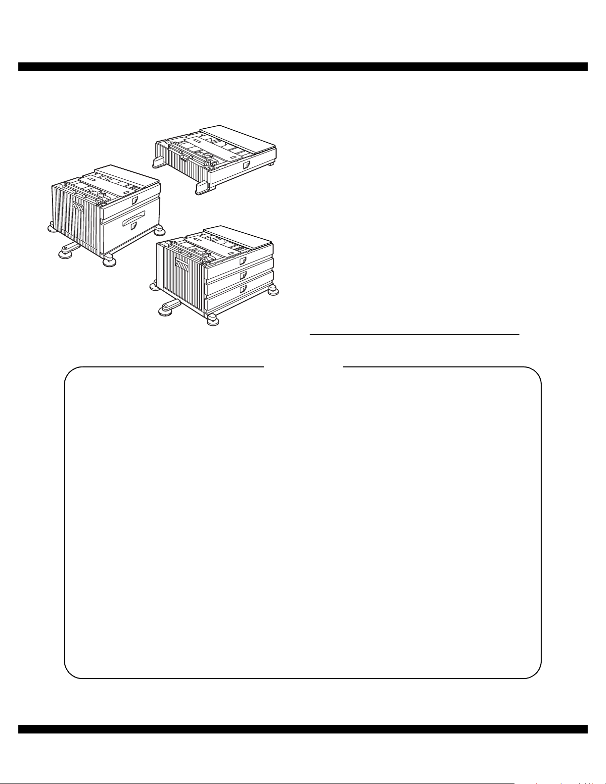
[1] PRODUCT OUTLINE
This unit is installed to one of the following machines to serve as a Paper feed module.
When installing the unit to one of the following machines, one of the multi-purpose tray (AR-MU2), the large capacity paper feed desk (AR-D28), and
the 3-stage paper feed desk (AR-D27) must be installed in advance.
Applicable models AR-M351N/M451N/M355N/M455N
AR-M351U/M451U/M355U/M455U
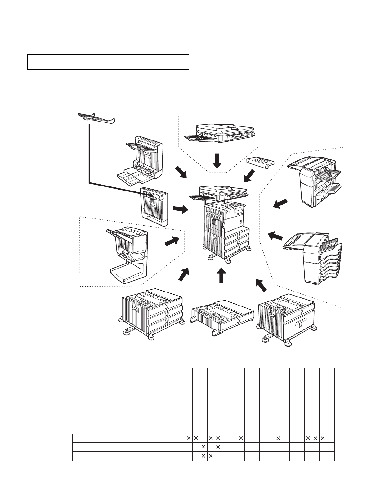
[2] CONFIGURATION
1. The AR-MU2 cannot be installed together with the saddle finisher (AR-FN7)/Scanner unit (AR-EF3).
Exit tray
(AR-TE3 or AR-DU4 Standard)
Duplex
module/bypass tray
Duplex module
(AR-DU3)
B/W scanner module/DSPF(AR-EF3)
Upper exit tray
extension
(AR-TE4)
Finisher
(AR-FN6)
Saddle stitch
finisher
(AR-FN7)
Stand/3 x 500 sheet
paper drawer
(AR-D27)
Related to paper feed unit
Multi purpose drawer
Stand/3 x 500 sheet paper drawer
Stand/MPD & 2000 sheet paper drawer
AR-MU2
AR-D27
AR-D28
Multi purpose drawer
(AR-MU2)
B/W scanner module/DSPF
Scanner rack
Multi purpose drawer
Stand/3 x 500 sheet paper drawer
Stand/MPD & 2000 sheet
Duplex module/bypass tray
Duplex module
Mail-bin
stacker
(AR-MS1)
Stand/MPD & 2000 sheet
paper drawer
(AR-D28)
Saddle stitch finisher
Finisher
Mail-bin stacker
Exit tray
Punch unit
Upper exit tray extension
Multi-function controller board
PS3 expansion kit
Print server card
Fax memory (8 MB)
Network scanner expansion kit
Facsimile expansion kit
Hard disk drive
AR-D28/D27/MU2 PRODUCT OUTLINE
1 – 1
Page 3
[3] SPECIFICATIONS
1. AR-D28
AR-D28
Type Stand MPD&2000 Sheet Paper Drawer
Transport speed To support 35-45 sheet/minute
Transport alignment Center alignment
Paper size 1 Tray A3, B4, A4, A4R, B5, B5R, A5R
2 Tray A4, 8.5" x 11"
How to change
the paper size
Factory
default paper
size setting
Media available for paper
feeding
Paper capacity
Paper type 1 Tray Plain, recycled, pre-printed, pre-punched,
Sizes to be
detected
Paper balance detection
1 Tray 8.5" x 11"
2 Tray The size guide plate is packed together.
1 Tray Plain paper : 60-128g/m² / 16-34lbs
2 Tray Plain 60-105g/m² / 16-28lbs
1 Tray Standard: 500sheets(80g/m²)
2 Tray 880+1,320sheets (64g/m²) /
2 Tray Plain, recycled, pre-printed, pre-punched,
1 Tray Auto detection-AB:
2 Tray Size setting by the serviceman
1 Tray Provided (paper empty and 3 steps)
2 Tray Enable (Paper empty and
(large capacity tray + multi purpose drawer)
11"x17", 8.5"x14", 8.5"x13", 8.5"x11",
8.5"x11"R, 5.5"x8.5"R
Executive, Japanese p/c, Monarch(enve lope)
Com-10(envelope), DL(envelope),
C5(envelope), ISO B5(envelope)
Guide adjustment by user/
Software setting by user
Index paper : 176g/m² / 47lbs
Cover paper : 200-205g/m² / 54-55lbs
Envelope : 75-90g/m², 20-24lbs
Transparency film
Media heavier than 105g/m² shou ld b e
*
A4/8.5x11" or smaller. Media heavier than
128g/m² should be fed from shorter edge.
Only single paper feed is enabled for over-
*
lay copy or copy on back-side of printed
paper.
Post card: 40sheets
Envelope: 40sheets
Transparency film: 40sheets
800+1,200sheets (80g/m²)
color, letter head, labels, heavy, transparency, Japanese p/c, envelope
(User can set bi-type for each of the above
paper type.)
color, letter head (User can set bi-type for
each of the above paper type.)
A3, B4, A4, A4R, B5, B5R, 8.5"x13", A5R
Auto detection-Inch:
11"x17", 8.5"x14", 8.5"x11", 8.5"x11"R,
7.25"x10.5"R, 5.5" x 8.5R
Manual (input detection):
postal card, Monarch(envelope),
Com-10(envelope), DL(envelope),
C5(envelope), ISO B5(envelope)
Ignore detection selectable:
6 steps (3 steps + 3 steps))
AR-D28
Paper loading system To be loaded from the upper side with
Tray ascent/
descent time
Dehumidification heater Not provided
Power consumption 32.2W or lower
Power source Supplied from main unit
External dimensions 589 x 630 x 404 (mm)
Occupied dimensions 963 x 665 (mm )
Weight Approx. 34kg
Ascent Within 12 seconds
Descent Own weight descent
front loading system
At paper empty, required time from
tray insert to the empty detection
(DC24V 1.3A / DC5V 0.2A)
2. AR-D27
AR-D27
Type Stand /3x500 Sheet Paper Drawer
Transport speed To support 35-45 sheet/minute
Transport alignment Center alignment
Paper size 1 Tray A3, B4, A4, A4R, B5, B5R, A5R
2 or 3
Tray
How to change the
paper size
Factory default paper
size setting
Media available for paper
feeding
Paper capacity
1 Tray Plain paper : 60-128g/m² / 16-34lbs
2 or 3
Tray
1 Tray Standard:500sheets(80g/m²)
2 or 3
Tray
(2 paper trays + 1 multi purpose drawer)
11"x17", 8.5"x14", 8.5"x13", 8.5"x11",
8.5"x11"R, 5.5"x8.5"R
Executive, Japanese p/c,Mona rch(e nvelope )
Com-10 (envelope), DL (envelope),
C5 (envelope), ISO B5 (envelope)
A3, B4, A4, A4R, B5, B5R
11"x17", 8.5"x14", 8.5"x13", 8.5"x11",
8.5"x11"R, 7.25"x10.5"R
Unit is delivered with paper guide set at max.
position in width. (Both of t wo ca ssettes. )
To be set to maximum paper guide width at
factory default status (for both trays)
Index paper : 176g/m² / 47lbs
Cover paper : 200-205g/m² / 54-55lbs
Envelope : 75-90g/m², 20-24lbs
Transparency film
Media heavier than 105g/m² should be
*
A4/8.5x11" or smaller.
Media heavier than 128g/m² should be
fed from shorter edge.
Only single paper feed is enabled for
*
overlay copy or copy on back-side of
printed paper.
Plain 60-105g/ m²/ 16-28lbs
Post card:40sheets
Envelope:40sheets
Transparency film:40sheets
Standard paper:500sheets x 2 (64g/m²)
AR-D28/D27/MU2 SPECIFICATIONS
3 – 1
Page 4
AR-D27
Paper type 1 Tray Plain, r e cy cl e d, pr e -p ri n ted , pr e -p un ch e d,
2 or 3
Tray
Sizes to be
detected
Paper balance detection Provided (paper empty and 3 steps)
Paper loading system To be loaded from the upper side with front
Tray ascent
/descent time
Dehumidification heater Not provided.
Power consumption 32.2W or lower
Power source Supplied from main unit
External dimensions 589 x 630 x 404 (mm)
Occupied dimensions 963 x 665 (mm)
Weight Approx. 32kg
1 Tray Auto detection-AB:
2 or 3
Tray
Ascent Within 7 seconds
Descent Own weight descent
color, letter head, labels, heavy,
transparency, Japanese p/c, envelope
(User can set bi-type for each of the above
paper type.)
Plain, recycled, pre-printed, pre-punched,
color, letter head
(User can set bi-type for each of the above
paper type.)
A3, B4, A4, A4R, B5, B5R, 8.5"x13", A5R
Auto detection-Inch:
11"x17", 8.5"x14", 8.5"x11", 8.5"x11"R,
7.25"x10.5"R, 5.5" x 8.5R
Manual (input detection):
postal card, Monarch(envelope),
Com-10(envelope), DL(envelope),
C5(envelope), ISO B5(envelope)
Ignore detection selectable:
Auto detection-AB
A3, B4, A4, A4R, B5, B5R, 8.5"x13"
Auto detection-inch
8.5"x14", 8.5"x13", 8.5"x11", 8.5"x11"R,
7.25"x10.5"R
loading system
At paper empty, required time from
tray insert to the empty detection
(DC24V 1.3A / DC5V 0.2A)
3. AR-MU2
AR-MU2
Type Multi purpose drawer
Transport speed To support 35-45 sheets/minute
Transport alignment Center alignment
Paper size A3, B4 , A 4, A4R, B5 , B 5 R , A 5 R
How to change the
paper size
Factory default paper
size setting
Media available for
paper feeding
Paper capacity Standard:500sheets(80g/m²)
Paper type Pla in , re cy c le d , p re - pr in te d , pr e- pu n ch e d,
Sizes to be detected Auto detection-AB:
Paper balance detection Provided (paper empty and 3 steps)
Paper loading system To be loaded from the upper side with front
Tray ascent/
descent time
Dehumidification heater Not provided.
Power consumption 24.5W or lower
Power source Supplied from main unit
External dimensions 654 x 567 x 144 (mm)
Occupied dimensions 654 x 567 (mm)
Weight Approx. 11kg
Ascent Within 7 seconds
Descent Own weight descent
11"x17", 8.5"x14", 8.5 "x13", 8.5" x11",
8.5"x11"R, 5.5"x8.5"R
Executive, Japanese p/c, Monarch(envel ope)
Com-10(envelope), DL(envelo pe),
C5(envelope), ISO B5(envelo pe)
Guide adjustment by user /
Software setting by user
To be set to maximum paper guide width at
factory default status.
Plain paper : 60-128g/m² / 16-34lbs
Index paper : 176g/m² / 47lbs
Cover paper : 200-205g/m² / 54-55lbs
Envelope : 75-90g/m², 20-24lbs
Transparency film
Media heavier than 105g/m² should be
*
A4/8.5x 1 1" or s ma ll e r.
Media heavier than 128g/m² should be fed
from shorter edge.
Only single paper feed is enabled for over lay
*
copy or copy on back-side of printe d paper.
Post card:40sheets
Envelope:40sheets
Transparency film:40sheets
color, letter head, labels, heavy,
transparency, Japanese p/c, envelope
(User can set bi-type for each of the abov e
paper type.)
A3, B4, A4, A4R, B5, B5R, 8.5"x13", A5R
Auto detection-Inch:
11"x17", 8.5"x14", 8.5"x11", 8.5"x11"R,
7.25"x10.5"R, 5.5" x 8.5R
Manual (input detection):
postal card, Monarch(envelope),
Com-10(envelope), DL(envelope),
C5(envelope), ISO B5(envelope)
Ignore detection selectable:
loading system
At paper empty, required time from
tray insert to the empty detection
(DC24V 1A / DC5V 0.1A)
AR-D28/D27/MU2 SPECIFICATIONS
3 – 2
Page 5
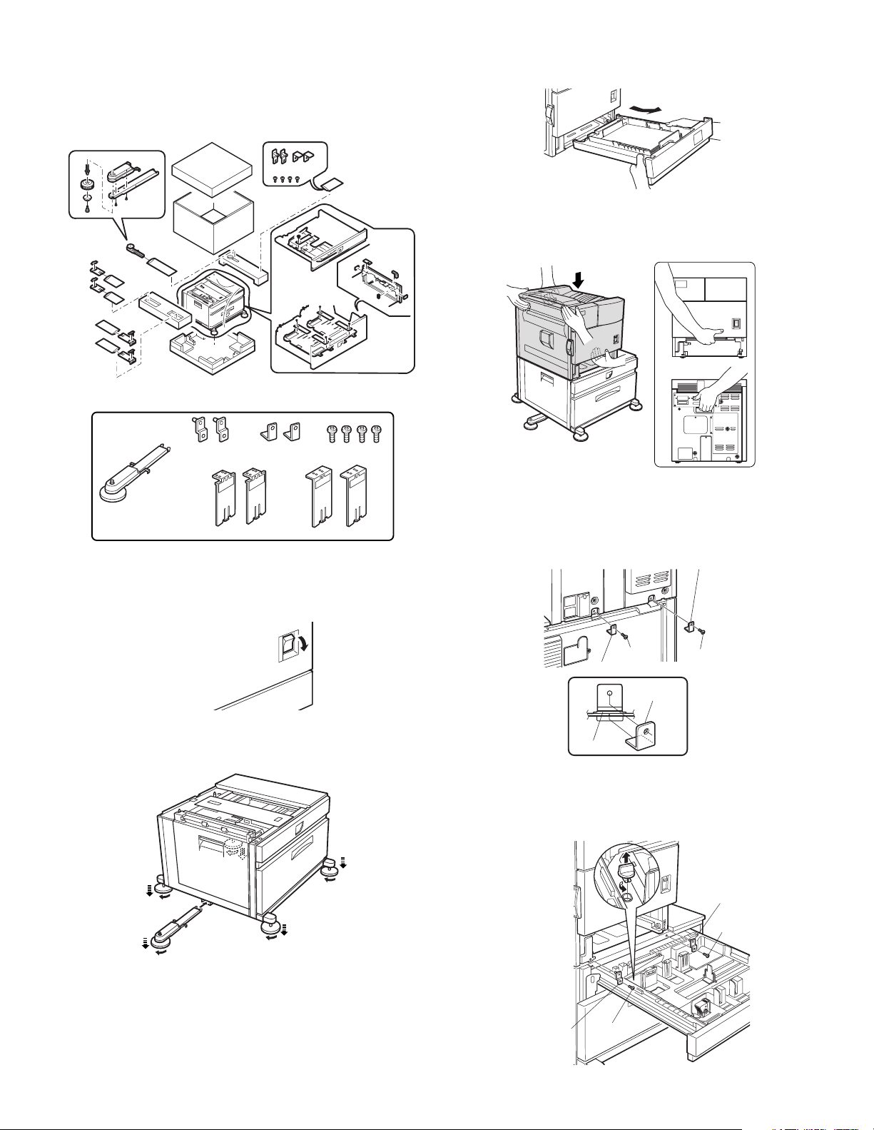
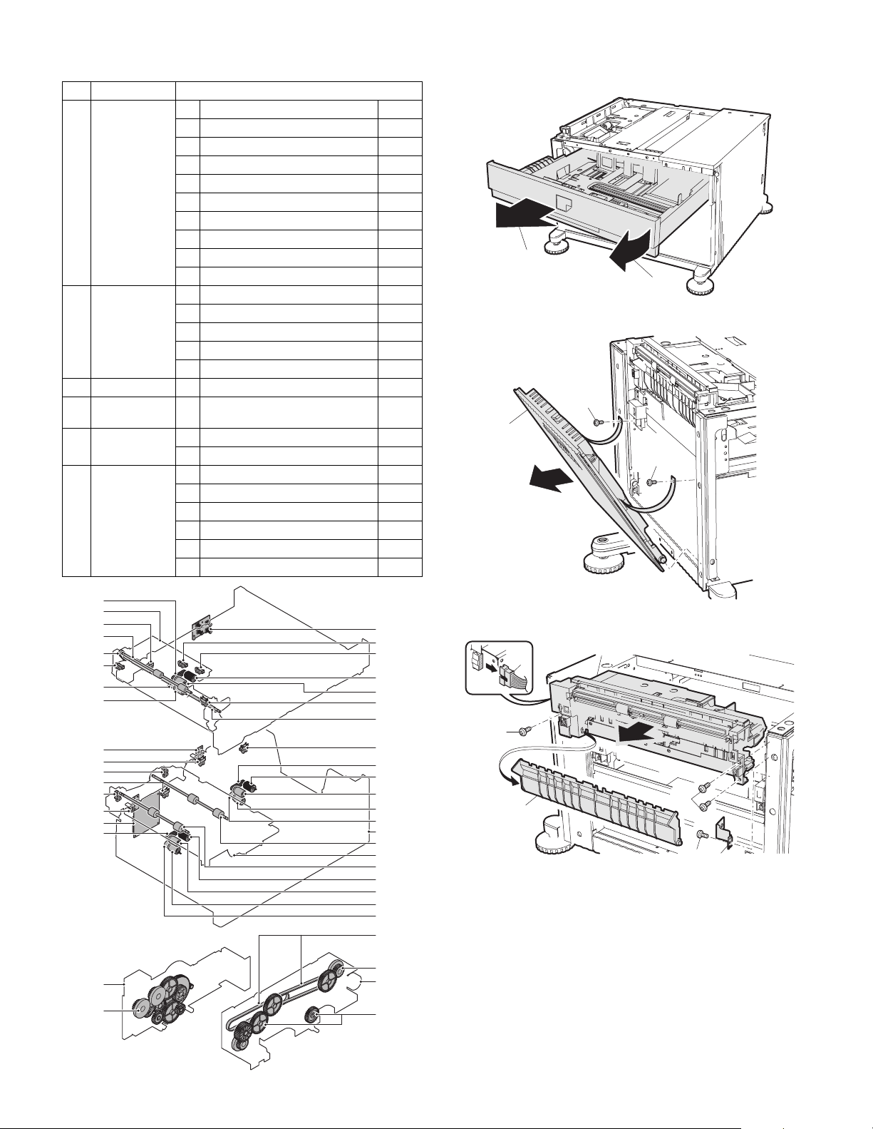
[4] UNPACKING AND INSTALLATION
1. AR-D28
<Before installation>
• Start installation after checking that the DATA and COMMUNICATION indicators on the operation panel are neither lit nor blinking.
<Partsincluded>
3) Put the main unit of the printer on the stand/paper drawer.
<1>Pull out the paper tray of the main unit until it stops and then
remove it by lifting both ends of the tray.
<2>Hold the main unit of the printer at the positions shown in the illus-
tration and put the main unit on the stand/paper drawer so that the
front side and the left side of the main un it are aligned to those of
the stand/paper drawer.
Frontside
Rearside
Leftadjuster:1pc.
Frontmounting
plates:2pcs.
Leftpaperguides:2pcs. Rightpaperguides:2pcs.
Rearmounting
plates:2pcs.
Screws(M4x6):
4pcs.
1) Turn off the main switch of the main unit of the printer.
Turn the main switch located on the front side of the printer to the
"OFF" position.
Then remove the power plug from the outlet.
"OFF"
2) Attach the adjusters and adjust them.
<1>Insert the left adjusters to the stand/paper drawer.
<2>Turn the each adjusters to lower them until they touch the floor.
Caution: For installation of the main unit, it must be held by two persons
and installed without haste.
4) Connect the main unit to the stand/paper drawer.
<1>Attach the rear mounting plates using a supplied screw for each.
Rear mounting plate
Screw
Rear mounting plate
Rear
mounting plate
Desk frame
Screw
Caution: Insert the rear mounting plates under the desk frame.
<2>Pull out the upper paper tray of the stand/paper drawer until it stops
and attach the front mounting pla tes usin g a supp lied scre w for each .
Then, remove the lock of the paper tray and cl ose the tray .
2
2
2
1
Be sure to attach the left adjuster to prevent overturning.
*
2
Caution: The lower tray cannot be pulled out unless the adjuster is low-
ered to the specified position.
AR-D28/D27/MU2 UNPACKING AND INSTALLATION
4 – 1
Front mounting
plate
Screw
Front
mounting plate
Screw
Page 6
<3>Reattach the paper tray of the main unit.
r
r
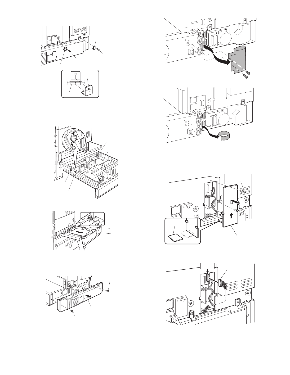
5) Connect the power supply I/F harness to the PCU PWB of the
main unit of the printer.
<1>Remove the screw that fixes the harness co ver of the main unit of
the printer and slide the harness cover up to remove it.
Process the harness cover as shown in the illustration.
Screw
Cut out.
Harness cove
<3>Reattach the power supply I/F harness cover to its original position
and fix it with the removed screw.
At this time, ensure that the power s upply I /F harnes s ar e ar ranged
as shown in the illustration.
• Fix the harness securely to the wire saddle.
Screw
Power supply
I/F harness
Harness cove
Wire saddle
Wire saddle
6) Attach the paper guides to the lower tray (large capacity tray) and
set the size.
Refer to "Setting and adjustment" described later.
If another peripheral device must be installed, carry out the following
*
step at the end of the installation work.
7) Adjust the position of the paper guides of the upper paper tray of
the stand/paper drawer.
Refer to "Setting and adjustment" described later.
8) Carry out the off center adjustment.
<2>Connect the power supply I/F harness connector (red, 22pin) to
CN11 (red connector) of the PCU PWB of the main unit of the
printer.
Connector
CN11
Connect the connector (white, 4pin) of power supply I/F harness to
the I/F connector (white, 4pin) of the main unit.
Remove the M4 screw shown in the illustration, insert the circle terminal of ground harness, and it fixes again.
2. AR-D27
<Before installation>
• Start installation after checking that the DATA and COMMUNICATION indicators on the operation panel are neither lit nor blinking.
<Parts included>
Screws (M4x6):
4 pcs.
Left adjuster: 1 pc.
Front mounting
plates: 2 pcs.
Rear mounting
plates: 2 pcs.
1) Turn off the main switch of the main unit of the printer.
Turn the main switch located on the front side of t he printer to the
"OFF" position.
Then remove the power plug from the outlet.
"OFF"
AR-D28/D27/MU2 UNPACKING AND INSTALLATION
4 – 2
Page 7
2) Attach the adjusters and adjust them.
<1>Insert the left adjusters to the stand/paper drawer.
<2>Turn the five adjusters to lower them until they touch the floor.
<2>Pull out the upper paper tray of the stand/paper drawer until it stops
and attach the front mounting pla tes usin g a supp lied scre w for each .
Then, remove the lock of the paper tray and close the tray.
Remove the locks of the middle tray and the lower tray similarly.
2
2
1
Be sure to attach the left adjuster to prevent overturning.
*
2
2
Caution: The lower tray cannot be pulled out unless the adjuster is low-
ered to the specified position.
3) Put the main unit of the printer on the stand/paper drawer.
<1>Pull out the paper tray of the main unit until it stops and then
remove it by lifting both ends of the tray.
<2>Hold the main unit of the printer at the positions shown in the illus-
tration and put the main unit on the stand/paper drawer so that the
front side and the left side of the main unit are aligned to those of
the stand/paper drawer.
Front side
Front mounting
plate
Screw
<3>Reattach the paper tray of the main unit.
Front
mounting plate
Screw
Rear side
Caution: For installation of the main unit, it must be held by two persons
and installed without haste.
4) Connect the main unit to the stand/paper drawer.
<1>Attach the rear mounting plates using a supplied screw for each.
Rear mounting plate
Screw
Rear mounting plate
Mounting plate
Screw
5) Connect the power supply I/F harness to the PCU PWB of the
main unit of the printer.
<1>Remove the screw that fixes the harness cover of the main unit of
the printer and slide the harness cover up to remove it.
Process the harness cover as shown in the illustration.
Screw
Cut out.
Harness cover
<2>Connect the power supply I/F harness connector (red, 22pin) to
CN11 (red connector) of the PCU PWB of the mai n unit of the pri nter.
Connector
CN11
Desk frame
Caution: Insert the rear mounting plates under the desk frame.
AR-D28/D27/MU2 UNPACKING AND INSTALLATION
4 – 3
Page 8
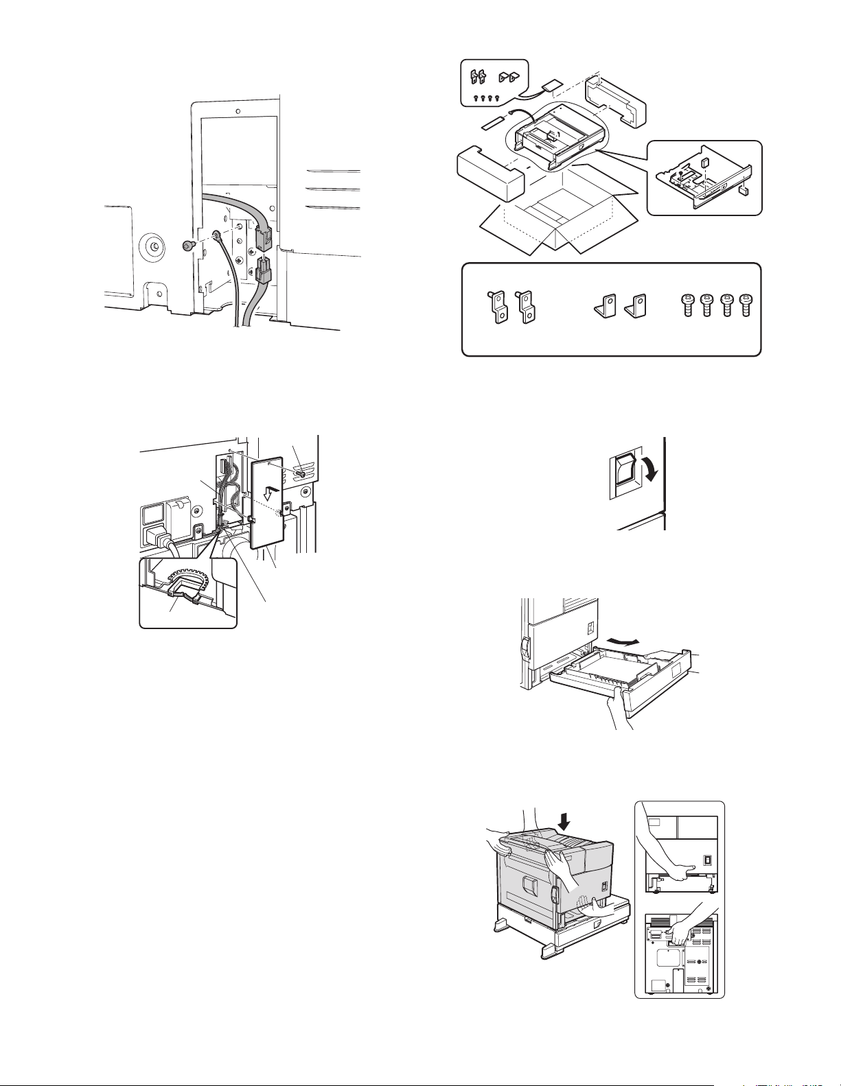
Connect the connector (white, 4pin) of power supply I/F harness to
r
the I/F connector (white, 4pin) of the main unit.
Remove the M4 screw shown in the illustration, insert the circle terminal of ground harness, and it fixes again.
3. AR-MU2
<Parts included>
<3>Reattach the harness cover to its original position and fix it with the
removed screw.
At this time, ensure that the power supply I/F harness is arranged
as shown in the illustration.
• Fix the harness securely to the wire saddle.
Screw
Power supply
I/F harness
Harness cove
Wire saddle
Wire saddle
6) Adjust the position of the paper guides of the upper paper tray of
the stand/paper drawer.
Refer to "Setting and adjustment" described later.
7) Carry out the off center adjustment.
Front mounting plates:
2 pcs.
Rear mounting plates:
2 pcs.
Screws (M4x8):
4 pcs.
1) Turn off the main switch of the main unit of the printer.
Turn the main switch located on the front side of the main unit to the
"OFF" position.
Then, remove the power plug of the main unit from the outlet.
"OFF"
2) Put the main unit of the printer on the multi purpose drawer.
<1>Pull out the paper tray of the main unit until it stops and then
remove it by lifting both ends of the tray.
<2>Hold the main unit of the printer at the positions shown in the illus-
tration and put the main unit on the multi purpose drawer so that the
front side and the left side of the main un it are aligned to those of
the multi purpose drawer.
Front side
Rear side
AR-D28/D27/MU2 UNPACKING AND INSTALLATION
Caution: For installation of the main unit, it must be held by two
persons and installed without haste.
4 – 4
Page 9
3) Connect the main unit of the printer to the multi purpose drawer.
r
<1>Attach the rear mounting plates using a supplied screw for each.
Rear mounting plate
<2>Remove the two screws that secure the Harness protection sheet.
Screw
Rear mounting plate
Tray frame
Screw
Mounting
plate
Caution: Insert the mounting plate under the desk frame.
<2>Pull out the paper tray of the multi purpose drawer until it stops and
attach the front mounting plates using a supplied screw for each.
Then, remove the lock of the paper tray and close the tray.
Front
mounting plate
Screw
Front mounting plate
Screw
<3>Remove the filam ent tape that secure the the power s upply I/F harness.
5) Connect the harness to the main unit of the printer.
<1>Remove the screw that fixes the harness cover of the main unit of
the printer and then slide the harness cover up to remove it.
Process the harness cover as shown in the illustration.
Screw
<3>Reattach the paper tray of the main unit of the printer.
4) Remove the multi rear cabinet.
<1>Remove the two screws that secure the multi rear cabinet.
Screw
Multi rear cabinet
Screw
Cut out.
Harness cove
<2>Connect the connector of the relay harness of the multi purpose
drawer to the connector of th e PCU PWB of the main unit of the pr inter.
CN10
Connector
AR-D28/D27/MU2 UNPACKING AND INSTALLATION
4 – 5
Page 10
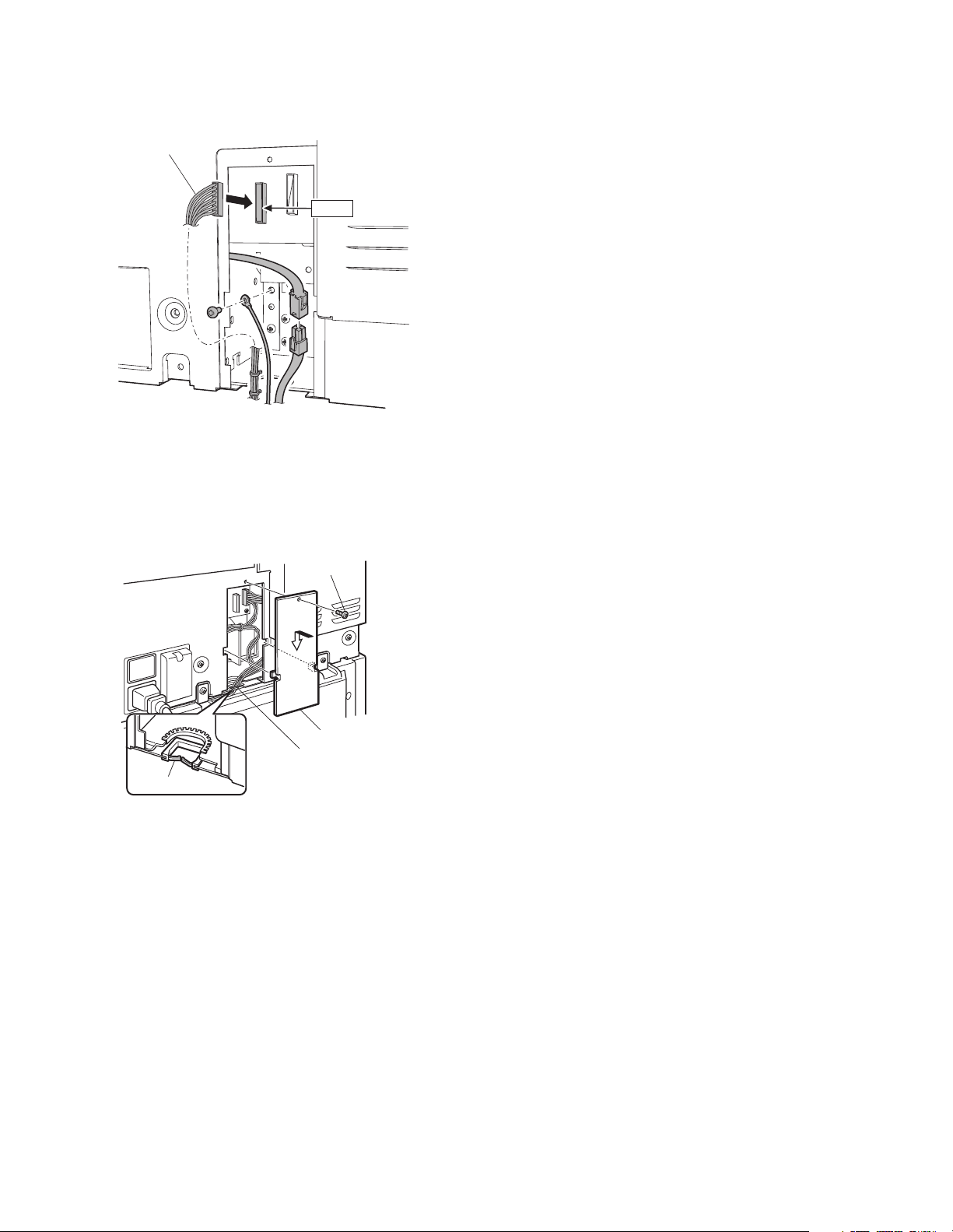
<3>Connect the connector (white, 4pin) of power supply I/F harness to
r
the I/F connector (white, 4pin) of the main unit.
Connect the power supply I/F harness co nnector (r ed, 22p in) to
CN11 (red connector) of the PCU PWB of th e main uni t of t he prin ter.
Remove the M4 screw shown in the illustration, insert the circle terminal of ground harness, and it fixes again.
Connector
CN11
For installation of a finisher or a mail-bin stacker,
*
see its installation manual.
6) Attach the harness cover.
Reattach the harness cover to its original position and fix it with the
removed screw.
At this time, ensure that the power supply I/F harness is arranged
as shown in the illustration.
• Fix the harness securely to the wire saddle.
Screw
Harness cove
Wire saddle
Wire saddle
If another peripheral device must be installed, carry out
*
the following step at the end of the installation work.
7) Adjust the position of the paper guides of the paper tray.
Refer to "Setting and adjustment" described later.
8) Carry out the off center adjustment.
AR-D28/D27/MU2 UNPACKING AND INSTALLATION
4 – 6
Page 11
[5] EXTERNAL VIEWS AND INTERNAL STRUCTURES
A. EXTERNAL VIEW
5
1
1
2
3
5
4
5
AR-D27
AR-D28
1 Multi-purpose tray (No. 2 tray) 2 No. 3 tray 3 No. 4 tray
4 Large capacity tray 5 Desk left door
B. INTERNAL STRUCTURE
(1) AR-D28
4
1.TPFD1
56 7
15
8910
1
AR-MU2
16
2.TPFD2
14
1213
3.TPFD3
1 Tandem tray paper transport sensor 1 (TPFD1) 7 Multipurpose tray paper take-up roller 13 Tandem tray 1 separation roller
2 Tandem tray paper transport sensor 2 (TPFD2) 8 Tandem tray transport roller 2 14 Tandem tray 1 paper feed roller
3 Tandem tray paper transport sensor 3 (TPFD3) 9 Tandem tray 2 paper feed roller 15 Tandem tray paper transport roller 1
4 Multipurpose tray paper transport roller 10 Tandem tray 2 paper take-up roller 16 Multipurpose tray
5 Multipurpose tray paper feed roller 11 Tandem tray 2 separation roller 17 Tandem tray 1
6 Multipurpose tray separation roller 12 Tandem tray 1 take-up roller 18 Tandem tray 2
AR-D28/D27/MU2 EXTERNAL VIEWS AND INTERNAL STRUCTURES
5 – 1
181117
Page 12
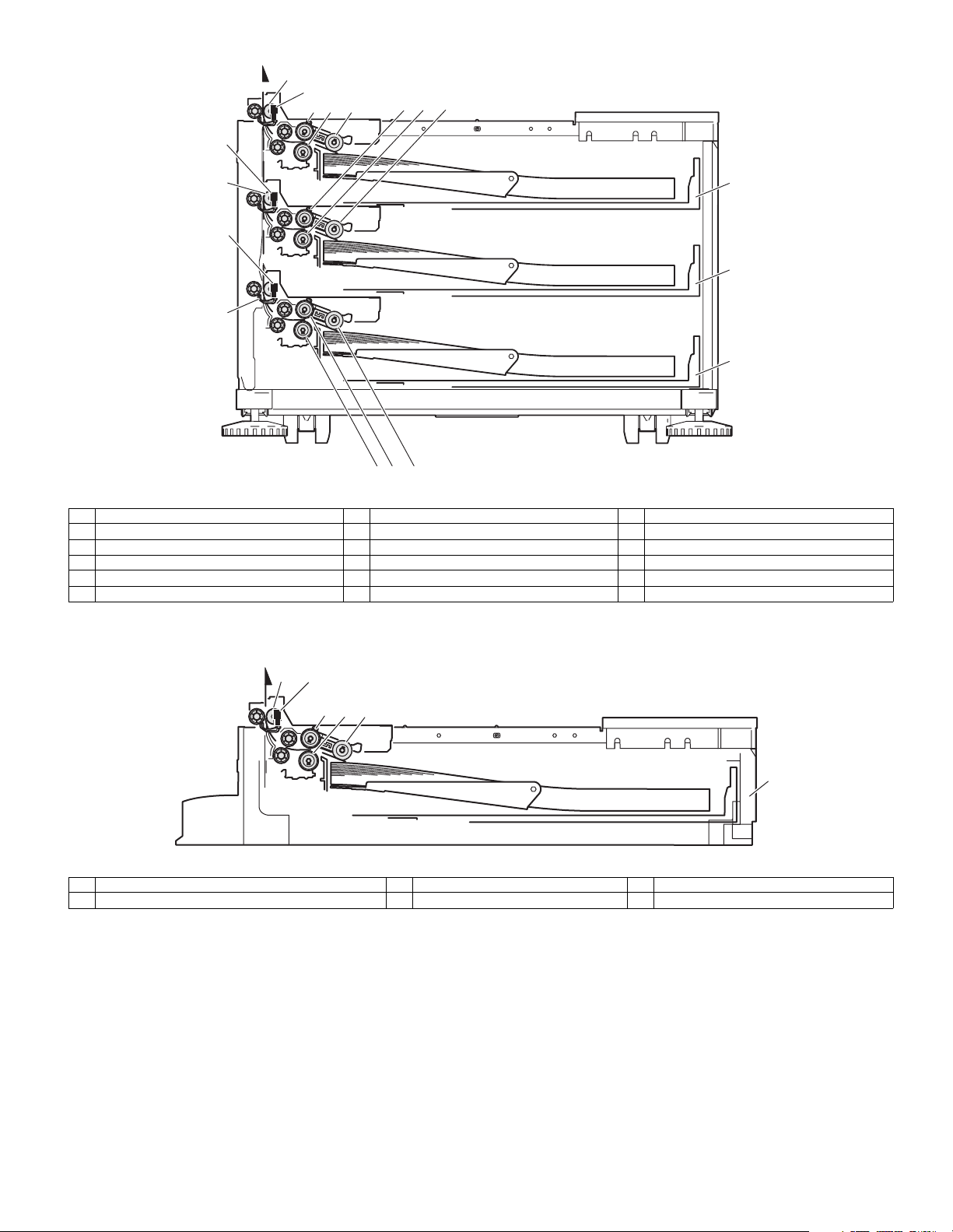
(2) AR-D27
2.DPFD2
4
1.DPFD1
5
67
910
11
8
3.DPFD3
15
14 13 12
16
17
18
1 Desk paper transport sensor 1 (DPFD1) 7 Multipurpose tray paper take-up roller 13 Desk tray 3 paper feed roller
2 Desk paper transport sensor 2 (DPFD2) 8 Desk transport roller 2 14 Desk tray 3 paper feed roller
3 Desk paper transport sensor 3 (DPFD3) 9 Desk tray 2 paper feed roller 15 Desk tray 3 paper transport roller
4 Desk paper transport roller 1 10 Desk tray 2 paper separation roller 16 Multipurpose tray
5 Multipurpose tray paper feed roller 11 Desk tray 2 take-up roller 17 Desk tray 2
6 Multipurpose tray separation roller 12 Desk tray 3 take-up roller 18 Desk tray 3
(3) AR-MU2
1.MCPPD
2
345
6
1 Multipurpose tray paper transport sensor (MCPPD) 3 Multipurpose tray paper feed roller 5 Multipurpose tray paper take-up roller
2 Multipurpose tray paper transport roller 4 Multipurpose tray separation roller 6 Multipurpose tray
AR-D28/D27/MU2 EXTERNAL VIEWS AND INTERNAL STRUCTURES
5 – 2
Page 13
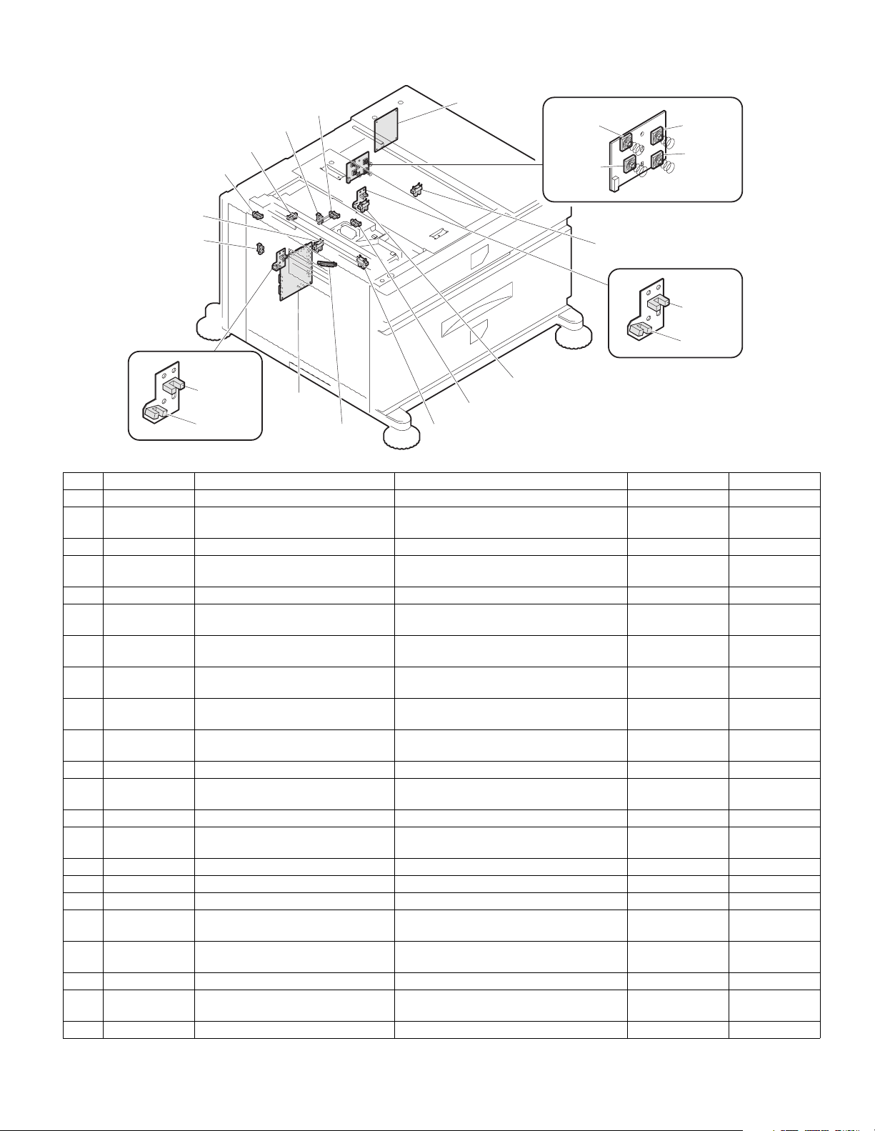
C. PWB, SENSOR
(1) AR-D28
2.TSPD1
3.TDRS
5.TPFD3
4.MCSPD
6.MCLUD
22.
21.
7.MCSS1
9.MCSS3
8.MCSS2
10.MCSS4
1.TPFD2
19.TLUD1
20.TPED1
18.
17.MCPWS
14.TSPD2
15.MCPED
16.TPFD1
11.TTSD
12.TLUD2
13.TPED2
Code Name Function Active condition Remark
1 TPFD2 Tandem tray paper transport sensor 2 Tandem tray paper transport detection L : Paper detected
2 TSPD1 Tandem 1 tray
remaining paper quantity sensor
Tandem 1 tray
remaining paper quantity detection
3 TDRS Side door open/close sensor Side door open/close detection H : Door closed
4 MCSPD MP tray remaining paper quantity
MP tray remaining paper quantity detection
sensor
5 TPFD3 Tandem tray paper transport sensor 3 Tandem tray paper transport detection L : Paper detected
6 MCLUD MP tray upper limit sensor MP tray upper limit detection H : Upper limit
detected
7 MCSS1 MP tray rear edge sensor 1 MP tray rear edge size detection L : When pressed In MP tray rear
edge size PWB
8 MCSS2 MP tray rear edge sensor 2 MP tray rear edge size detection L : When pressed In MP tray rear
edge size PWB
9 MCSS3 MP tray rear edge sensor 3 MP tray rear edge size detection L : When pressed In MP tray rear
edge size PWB
10 MCSS4 MP tray rear edge sensor 4 MP tray rear edge size detection L : When pressed In MP tray rear
edge size PWB
11 TTSD Tandem tray open/close sensor Tandem tray open/close detection H : Tray closed
12 TLLD2 Tandem 2 tray upper limit sensor Tandem tray 2 upper limit detection L : Upper limit
detected
13 TPED2 Tandem 2 tray paper empty sensor Tandem tray 2 paper empty detection H : Paper loaded
14 TSPD2 Tandem 2 tray
remaining paper quantity sensor
Tandem 2 tray
remaining paper quantity detection
15 MCPED MP tray paper empty sensor MP tray paper empty detection L : Paper loaded
16 TPFD1 Tandem tray paper transport sensor 1 Tandem tray paper transport detection L : Paper detected
17 MCPWS MP tray width sensor MP tray paper width detection Slide volume
18 Control PWB Control PWB Communication with the machine,
machine operation control
19 TLLD1 Tandem 1 tray upper limit sensor Tandem tray 1 upper limit detection L : Upper limit
detected
20 TPED1 Tandem 1 tray paper empty sensor Tandem tray 1 paper empty detection H : Paper loaded
21 MP tray rear
MP tray rear edge size PWB M ulti-purpos e tray rear edge size detection
edge size PWB
22 Power I/F PWB Power I/F PWB Distributed the po wer supply fr om the main unit .
AR-D28/D27/MU2 EXTERNAL VIEWS AND INTERNAL STRUCTURES
5 – 3
Page 14
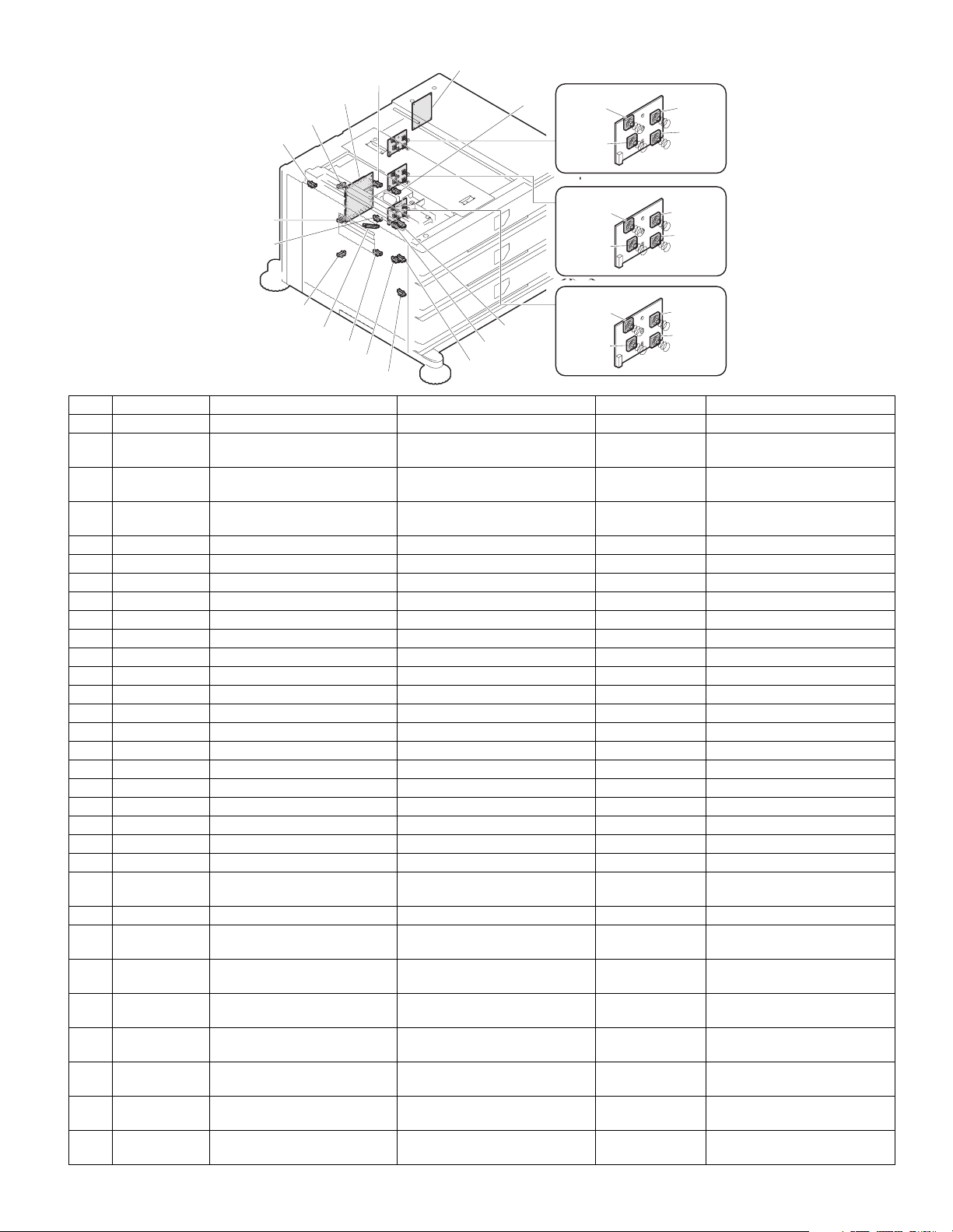
(2) AR-D27
1.DDRS
2.MCSPD
3.
4.MCLUD
31.
5.MCPED
28.
6.MCSS1
8.MCSS3
29.
7.MCSS2
9.MCSS4
27.DSPD1
26.DLUD1
25.DSPD2
24.MCPWS
23.DLUD2
22.DPED2
21.DPFD3
19.DPED1
20.DPFD2
10.DCSS11
12.DCSS13
30.
14.DCSS21
18.DPFD1
16.DCSS23
11.DCSS12
13.DCSS14
15.DCSS22
17.DCSS24
Code Name Function Active condition Remark
1 DDRS Side door open/close sensor Side door open/close detection H : Door closed
2MCSPD MP tray
remaining paper quantity sensor
MP tray
remaining paper quantity detection
3 Control PWB Control PWB C om mu nication with the machine,
machine operation control
4 MCLUD MP tray upper limit sensor MP tray upper limit detection H : Upper limit
detected
5 MCPED MP tray paper empty sensor MP tray paper empty detection L : Paper loaded
6 MDSS1 MP tray rear edge sensor 1 MP tray rear edge size detection L : When pressed In MP tray rear edge size PWB
7 MCSS2 MP tray rear edge sensor 2 MP tray rear edge size detection L : When pressed In MP tray rear edge size PWB
8 MCSS3 MP tray rear edge sensor 3 MP tray rear edge size detection L : When pressed In MP tray rear edge size PWB
9 MCSS4 MP tray rear edge sensor 4 MP tray rear edge size detection L : When pressed In MP tray rear edge size PWB
10 DCSS 1 1 No. 3 tray rear edge sensor 1 No. 3 tray rear edge size detection L : When pressed In No. 3 tray rear edge size PWB
11 DCSS 1 2 No. 3 tray rear edge sensor 2 No. 3 tray rear edge size detection L : When pressed In No. 3 tray rear edge size PWB
12 DCSS 1 3 No. 3 tray rear edge sensor 3 No. 3 tray rear edge size detection L : When pressed In No. 3 tray rear edge size PWB
13 DCSS 1 4 No. 3 tray rear edge sensor 4 No. 3 tray rear edge size detection L : When pressed In No. 3 tray rear edge size PWB
14 DCSS 2 1 No. 4 tray rear edge sensor 1 No. 4 tray rear edge size detection L : When pressed In No. 4 tray rear edge size PWB
15 DCSS 2 2 No. 4 tray rear edge sensor 2 No. 4 tray rear edge size detection L : When pressed In No. 4 tray rear edge size PWB
16 DCSS 2 3 No. 4 tray rear edge sensor 3 No. 4 tray rear edge size detection L : When pressed In No. 4 tray rear edge size PWB
17 DCSS 2 4 No. 4 tray rear edge sensor 4 No. 4 tray rear edge size detection L : When pressed In No. 4 tray rear edge size PWB
18 DPF D1 Desk paper transport sensor 1 Desk paper transport detection L : Pape r detected
19 DPED1 N. 3 tray paper empty sensor N. 3 tray paper empty detection L : Paper loaded
20 DPF D2 Desk paper transport sensor 2 Desk paper transport detection L : Paper detected
21 DPF D3 Desk paper transport sensor 3 Desk paper transport detection L : Paper detected
22 DPE D 2 No. 4 tray paper empty sensor No. 4 tray paper empty detection L : Paper loaded
23 DLUD2 No. 4 tray upper limit sensor No. 4 tray upper limit detection H : Upper limit
detected
24 MCPWS MP tray width sensor MP tray paper width detection Analog voltage Slide volume
25 DSP D 2 No. 4 tray
remaining paper quantity sensor
No. 4 tray
remaining paper quantity detection
26 DLUD1 No. 3 tray upper limit sensor No. 3 tray upper limit detection H : Upper limit
detected
27 DSP D 1 No. 3 tray
remaining paper quantity sensor
28 MP tray rear
MP tray rear edge size PWB MP tray rear edge size detection
No. 3 tray
remaining paper quantity detection
edge size PWB
29 No. 3 tray rear
No. 3 tray rear edge size PWB No. 3 tray rear edge size detection
edge size PWB
30 No. 4 tray rear
No. 4 tray rear edge size PWB No. 4 tray rear edge size detection
edge size PWB
31 Power I/F PWB Power I/F PWB Distributed the power supply from
the main unit.
AR-D28/D27/MU2 EXTERNAL VIEWS AND INTERNAL STRUCTURES
5 – 4
Page 15
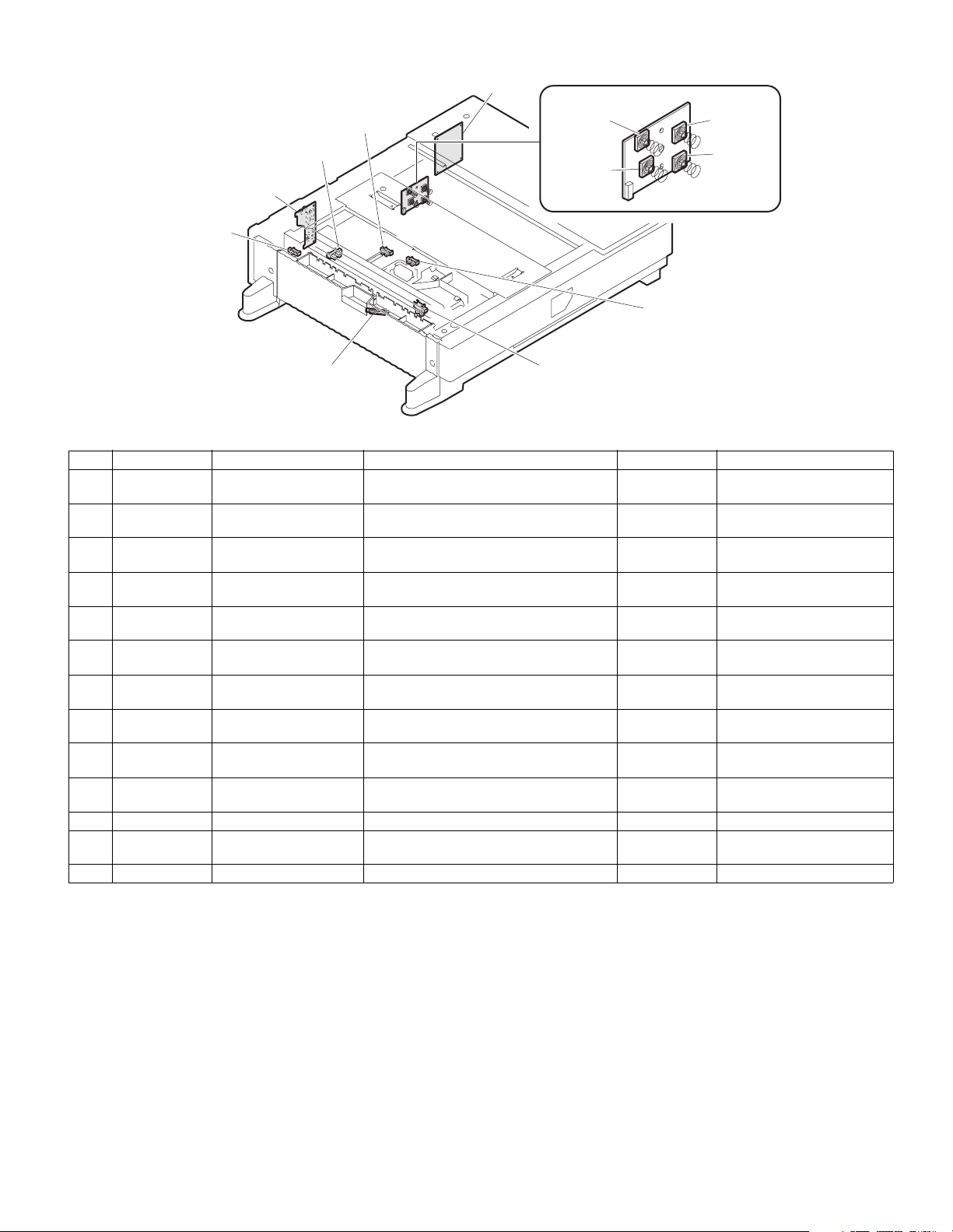
(3) AR-MU2
13.
4.MCLUD
3.MCSPD
2.
1.MCDRS
11.MCPWS
12.
5.MCSS1
7.MCSS3
10.MCPPD
6.MCSS2
8.MCSS4
9.MCPED
Code Name Function Active condition Remark
1 MCDRS MP door open / close
MP left door open / close detection H : Door closed
sensor
2 Control PWB Control PWB Communication with the machine,
machine operation control
3 MCSPD MP tray remaining paper
quantity sensor
MP tray remaining paper quantity detection L : When
pressed
4 MCLUD MP tray upper limit sensor MP tray upper limit detection H : Upper limit
detected
5 MDSS1 MP tray rear edge sensor 1 MP tray rear edge size detection L : When
In MP tray rear edge size PWB
pressed
6 MCSS2 MP tray rear edge sensor 2 MP tray rear edge size detection L : When
In MP tray rear edge size PWB
pressed
7 MCSS3 MP tray rear edge sensor 3 MP tray rear edge size detection L : When
In MP tray rear edge size PWB
pressed
8 MCSS4 MP tray rear edge sensor 4 MP tray rear edge size detection L : When
In MP tray rear edge size PWB
pressed
9 MCPED MP tray paper empty
MP tray paper empty detection L : Paper loaded
sensor
10 MCPPD MP transport sensor Detection of paper on the path L : Paper
detected
11 MCPWS MP tray width sensor MP tray paper width detection Analog voltage Slide volume
12 MP tray rear
edge size PWB
MP tray rear
edge size PWB
MP tray rear edge size detection
13 Power I/F PWB Power I/F PWB Distributed the power suppl y f rom th e mai n uni t.
AR-D28/D27/MU2 EXTERNAL VIEWS AND INTERNAL STRUCTURES
5 – 5
Page 16
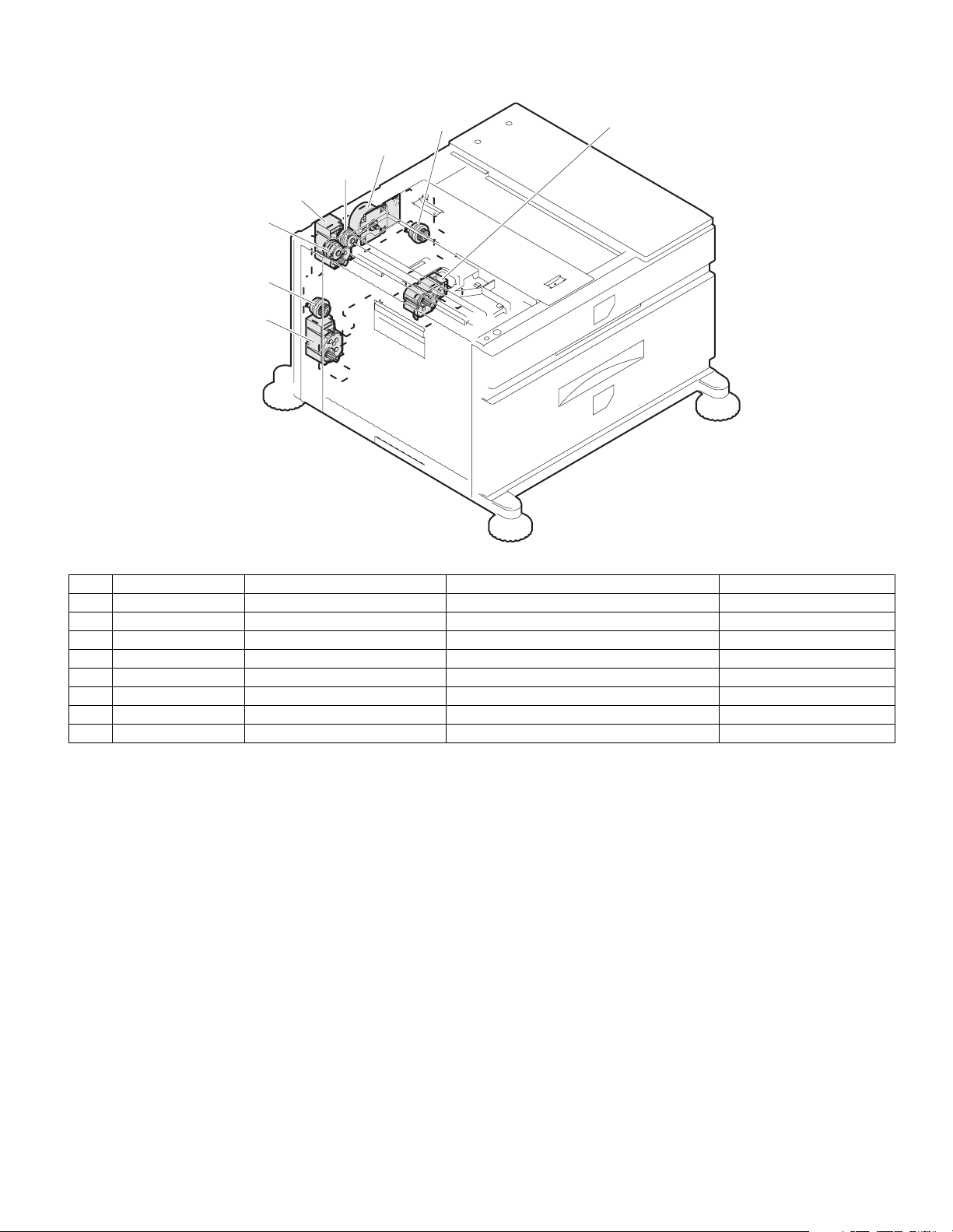
D. MOTOR, CLUTCH
(1) AR-D28
3.TPFCL
2.TPCL1
1.TLUM1
4.MCLUM
5.MCPCL
6.TMM
7.TPCL2
8.TLUM2
Code Name Function Remark
1 TLUM1 Tandem tray 1 lift-up motor Tandem tray 1 lift-up
2 TPCL1 Tandem tray 1 paper feed clutch Clutch for paper feed from tandem tray 1
3 TPFCL LCC transport clutch Clutch for transport from LCC desk
4 MCLUM Multi-purpose tray lift-up motor Multi-purpose tray lift-up
5 MCPCL Multi-purpose paper feed clutch Clutch for paper feed from Multi-purpose tray
6 TMM LCC transport motor LCC desk paper transport
7 TPCL2 Tandem tray 2 paper feed clutch Clutch for paper feed from tandem tray 2
8 TLUM2 Tandem tray 2 lift-up motor Tandem tray 2 lift-up
AR-D28/D27/MU2 EXTERNAL VIEWS AND INTERNAL STRUCTURES
5 – 6
Page 17
(2) AR-D27
5.MCPCL
4.MCLUM
3.DPFCL
2.DLUM1
1.DLUM2
6.DMM
8.DPCL2
7.DPCL1
Code Name Function Remark
1 DLUM2 Desk 2 tray lift-up motor Gate switch between duplex and paper exit
2 DLUM1 Desk 1 tray lift-up motor Cooling the machine and inside of ADU
3 DPFCL Desk transport clutch Clutch for transport
4 MCLUM Multi-purpose tray lift-up motor Multi-purpose tray lift-up
5 MCPCL Multi-purpose paper feed clutch Clutch for paper feed from Multi-purpose tray
6 DMM 3 tray desk transport motor No. 3 tray desk paper transport
7 DPCL1 Desk 1 tray paper feed clutch Clutch for paper feed from desk tray 1
8 DPCL 2 Desk 2 tray paper feed clutch Clutch for paper feed from desk tray 2
(3) AR-MU2
4.MCM
3.MCPCL
2.MCLUM
1.MCFCL
Code Name Function Remark
1 MCFCL Multi-purpose tray transport clutch Multi-purpose tray transport clutch
2 MCLUM Multi-purpose tray lift-up motor Multi-purpose tray lift-up
3 MCPCL Multi-purpose paper feed clutch Clutch for paper feed from Multi-purpose tray
4 MCM Multi-purpose tray transport motor Multi-purpose tray paper transport
AR-D28/D27/MU2 EXTERNAL VIEWS AND INTERNAL STRUCTURES
5 – 7
Page 18
[6] ADJUSTMENTS
PAPER TRAY
SETTINGS
TA
PRINTER
CONDITION
TRAY SETTINGS
PAPER TRAY SETTINGS
CUSTOM SETTINGS
TYPE / SIZE
TRAY 2
PER TRAY SETTINGS
PRINT
COPY
I-FAX
DOC.
FILING
FAX
1. CHANGING THE PAPER SIZE
[Upper tray(Tray2)]
• A3 to A5R(11x7 to 5-1/2x8-1/2R) size plain paper can be set.
• Special paper can be set.
• Two maximum height lines are indicated: one for plain paper and one
for special paper.
[Middle/Lower tray(Tray3/4)]
• A4, B5 or 8-1/2" x 11" size plain paper can be set.
Use the following procedure to change the size as needed.
1) Pull out paper tray.
If paper remains in the tray, remove it.
2) Adjust the guide plates A and B in the tray to the length and width of
the paper.
The guide plates A and B are slidable. Adjust them to the paper size
to be loaded while squeezing their lock levers.
3) Load paper into the tray.
Do not exceed red line when loading special paper to upper tray.
4) Gently push tray into the machine.
Push the tray firmly all the way into the machine.
5) Set the paper size.
Be sure to set the paper size and paper type re ferring to "2.Setting
the paper type and paper size".
If this is not done, paper misfeeds will occur.
2. SETTING THE PAPER TYPE AND PAPER SIZE
Follow these steps to change the paper type setting if the paper type is
changed in either paper tray. For the paper types that ca n be used in
each tray.
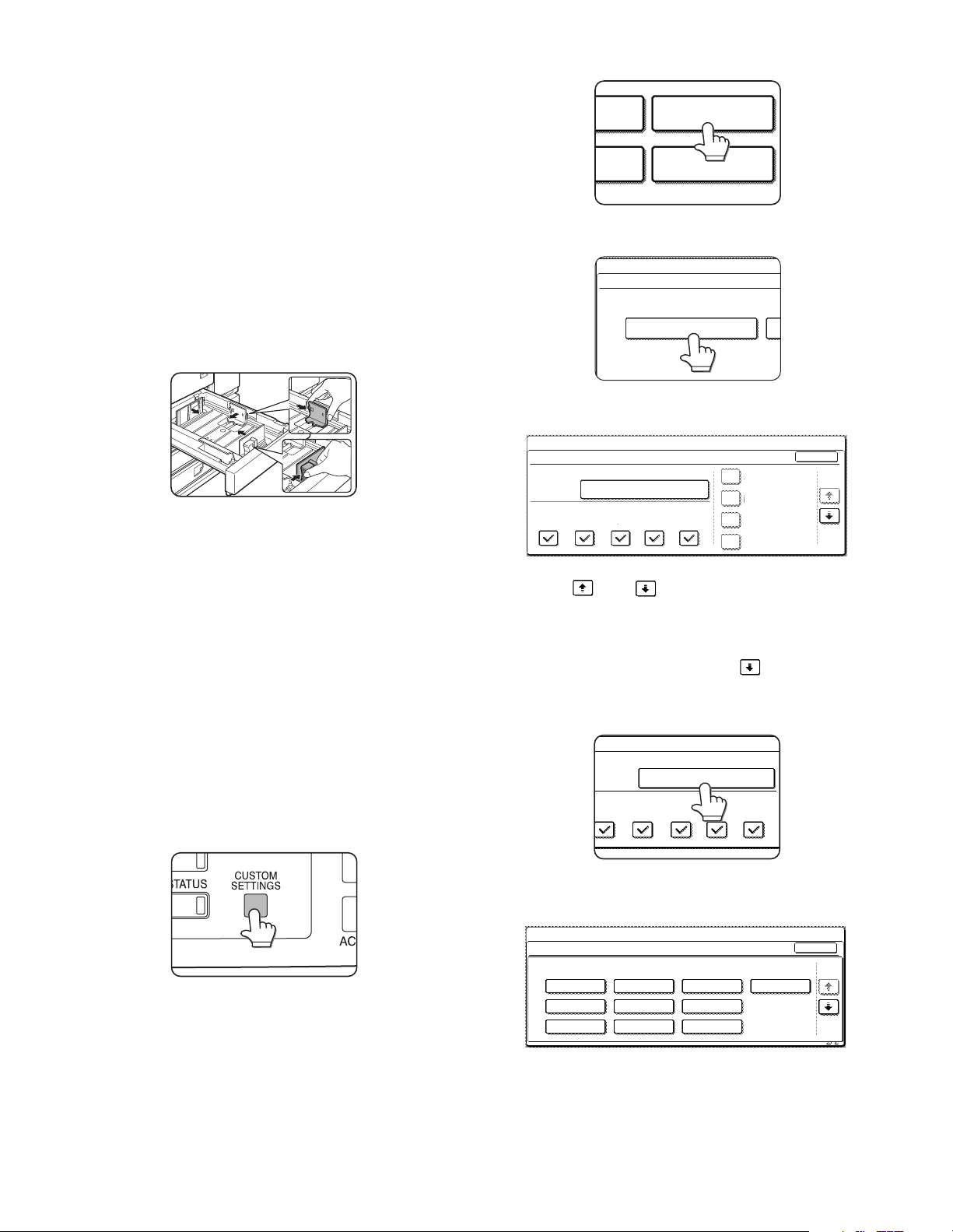
1) Press the [CUSTOM SETTINGS] key.
The custom setting menu screen will appear.
2) Touch the [PAPER TRAY SETTINGS] key.
The paper tray selection screen will appear.
3) Touch the [TRAY SETTINGS] key.
4) Display the setting screen of the desired paper tray.
CUSTOM SETTINGS
PAPER TRAY SETTINGS
TRAY 1
COPY
PRINT
FAX
TYPE / SIZE
PLAIN / A4
I-FAX
DOC.
FILING
FIXED PAPER SIDE
DISABLE DUPLEX
DISABLE STAPLE
DISABLE PUNCH
OK
1/4
Touch the key or key to display the setting screen of the
desired paper tray.
Note: To automatically switch to a tray with the same size and type of
paper (if there is one) in the event that the paper tray runs out of
paper, display the last screen with the key and select [AUTO
TRAY SWITCHING].
5) Touch the [TYPE/SIZE] key.
PLAIN / A4
6) Select the type of paper that was loaded in the tray.
Example: The paper type of tray 2 is selected
Touch the desired paper type to select it.
The paper size setting screen will appear.
Note: Heavy paper, label sheets and transparency film cannot be used
in trays 1, 3, and 4. Envelopes can only be placed in tray 2.
AR-D28/D27/MU2 ADJUSTMENTS
6 – 1
CUSTOM SETTINGS
TRAY 2 TYPE/SIZE SETTING
SELECT THE PAPER TYPE.
PLAIN
PRE-PRINTED PRE-PUNCHED
RECYCLED
LETTER HEAD
COLOUR
HEAVY PAPER
LABELS
TRANSPARENCY
CANCEL
1/2
ENVELOPE
1/2
Page 19
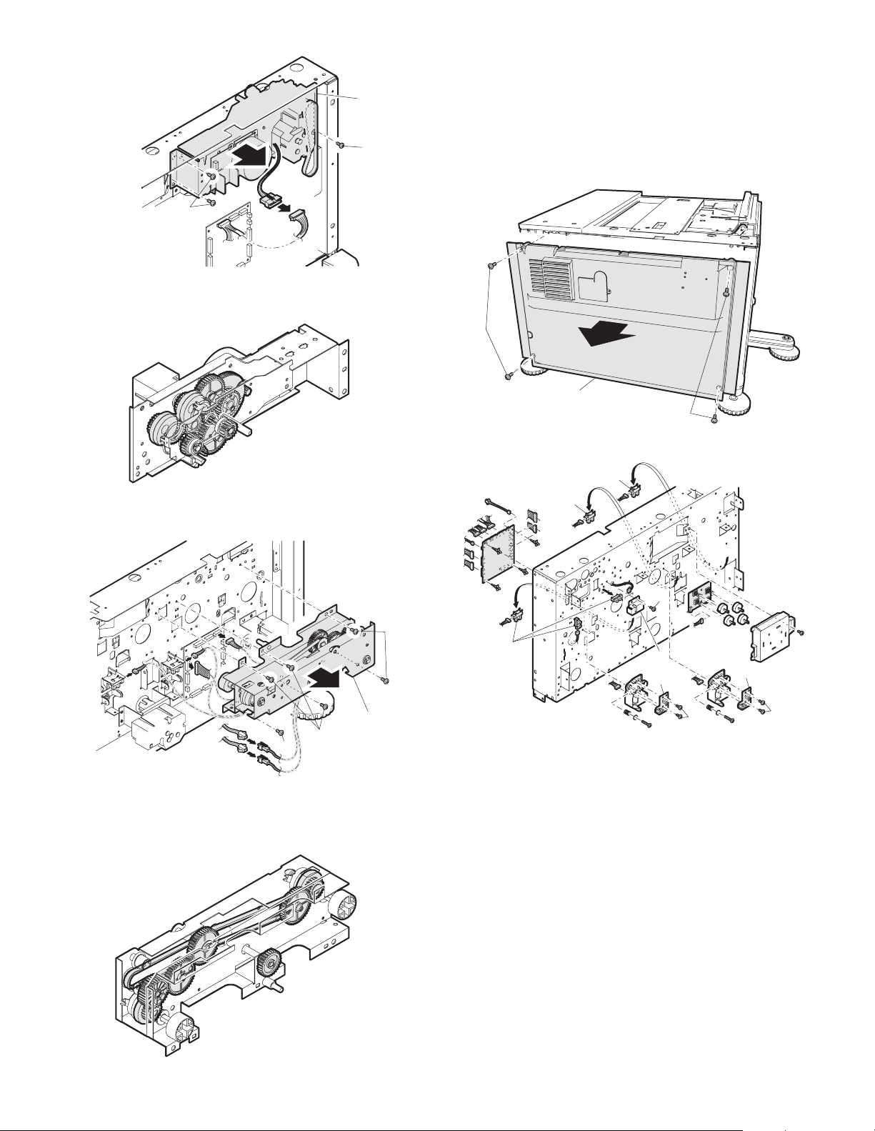
[7] DISASSEMBLY AND ASSEMBLY, MAINTENANCE
MCPWS
MCSPD
TLUD1
TAN Sensor PWB
TSPD2
TPFD2
MCSS3
TLUM2
TPFCL
TPCL1
TPCL2
MCPCL
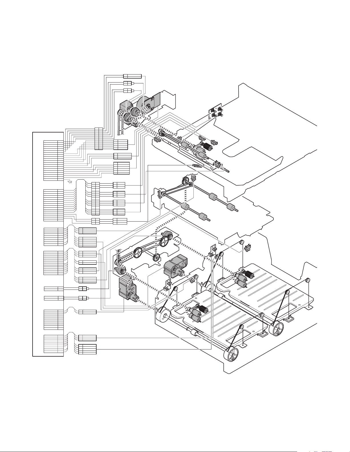
(1) AR-D28
A. MAJOR PARTS AND SIGNAL FUNCTIONS
2
MCLUM/
+24V
1
PHR-2
1221
SMP-02V-NC
SMR-02V-N
212
1
SMP-02V-BC
SMR-02V-B
MCLUM
MCPCL
TMM
MPT LD PWB
MCSS1
MCSS3
MCSS2
MCSS4
TAN Control PWB
CN-D
VB(+24V)
TPFCL/
VB(+24V)
MCPCL/
+24V(MCLUM) 5
VB(+24V)
GND1(P-GND)
TMM/
TMMCLK/
TMM-T
MCSPD
VD(+5V)
GND2(S-GND)
MCSS1
GND2(S-GND)
MCSS2 17
MCSS3
MCSS4
F-GND
PHDR-20VS-1
CN-E
GND2(S-GND) 1
MCLUD
VD(+5V)
VD(+5V)
GND2(S-GND)
MCPED
GND2(S-GND)
TDRS
VD(+5V)
VD(+5V)
GND2(S-GND)
TPFD1
MCPWS2313
MCPWS
VD(+5V)
N.C.
PHDR-16VS-1
CN-I
S-GND
TPFD3
VD(+5V)
S-GND
TLUD1
VD(+5VR)
N.C
TPED1
VD(+5V)
PHR-9
CN-B
S-GND 1
TSPD1
VD(+5V)
TLUM2/
VB(TLUM2)
S-GND
TPFD2
VD(+5V)
S-GND
TTSD1211
VD(+5V)
PHR-12
CN-C
VB(+24V)
TPCL1/12
PHR-2
CN-G
VB(+24V) 1
TPCL2/
PHR-2-R(RED)
CN-J
TLUM1/
VB(TLUM1)
N.C.
N.C.
N.C.
N.C.
N.C.
N.C.
N.C.
N.C.
PHR-10
CN-A
S-GND
TSPD2
VD(+5V)
S-GND
TLUD2
VD(+5VR)
N.C
TPED2
VD(+5V)
PHR-9
(RED)
1
2
3
4
6MCLUM/
7
8
9
10
11
12
13
14
15
16
18
19
20
2
4
5
6
7
8
9
10
11
12
14
15
16
1
2
3
4
5
6
7
8
9
2
3
4
5
6N.C.
7
8
9
10
2
1
2
3
4
5
6
7
8
9
10
1
2
3
4
5
6
7
8
9
SRA-21T-4
SMP-02V-BC SMR-02V-B
SMP-02V-NC SMR-02V-N
SMP-11V-NC
SMP-03V-BC
12VD(+5V)
2
3
179228-3
1
TPED1
TLUD1
S-GND
3
VD(+5VR)
4
VD(+5V)
5
PHR-5
1 VD(+5V)
2
3
179228-3
1
2
PHR-2
1
2
3
179228-3
1
2
3
179228-3
1
212
1
212
2
PHR-2
1
2
3
179228-3
1
2
3
4
5
PHR-5
TPFD3
S-GND
TSPD1
S-GND
VB(+24V)
TLUM2
VD(+5V)
TPFD2
S-GND
VD(+5V)
TTSD
S-GND
VB(+24V)1
TLUM1/
VD(+5V)
TSPD2
S-GND
TPED2
TLUD2
S-GND
VD(+5VR)
VD(+5V)
11
10
9
8
7
6
5
4
3
2
1
18
18
17
17
16
16
15
15
14
14
13
13
9
8
7
6
5
4
3
22
11
10
9
8
7
6
5
4
3
2
1
SMR-11V-N
9
8
7
6
5
4
SMR-18V-BSMP-18V-BC
3
11
SMR-03V-B
TPFCL
5
TMMCLK/
4
TMM-T
3
TMM/
2
GND1
1
+24V
PHR-5
+5V31
MCSPD2
GND2
179228-3
1N.C.
2
GND2
MCSS1
3
4
MCSS2
MCSS35
MCSS4
6
PHR-6
+5V
1
MCLUD
2
3
GND2
179228-3
+5V
1
2
TPFD1
GND2
3
179228-3
+5V
1
TDRS
2
GND2
3
179228-3
+5V
1
MCPED
2
3
GND2
179228-3
2T
MCPWS
1T
MCPWS2
3T
VAREF
TLUM1
TPCL1
TDRS
TPFD2
TPCL2
TLUM2
TAN Sensor PWB
TPED1
TLUD1
MCSPD
MCPWS
TPFD3
TAN Sensor PWB
TPED2
TSPD1
MCLUD
MCPED
TPFD1
TLUD2
TSPD2
TTSD
AR-D28/D27/MU2 DISASSEMBLY AND ASSEMBLY, MAINTENANCE
7 – 1
Page 20

Code Name Function Remark
TPFD2 Tandem tray paper transport sensor 2 Tandem tray paper transport detection
TSPD1 Tandem 1 tray remaining paper quantity sensor Tandem 1 tray remaining paper quantity detection
TDRS Side door open/close sensor S ide door open/close detection
MCSPD MP tray remaining paper quantity sensor MP tray remaining paper quantity detection
TPFD3 Tandem tray paper transport sensor 3 Tandem tray paper transport detection
MCLUD MP tray upper limit sensor MP tray upper limit detection
MCSS1 MP tray rear edge sensor 1 MP tray rear edge size detection In MP tray rear edge size PWB
MCSS2 MP tray rear edge sensor 2 MP tray rear edge size detection In MP tray rear edge size PWB
MCSS3 MP tray rear edge sensor 3 MP tray rear edge size detection In MP tray rear edge size PWB
MCSS4 MP tray rear edge sensor 4 MP tray rear edge size detection In MP tray rear edge size PWB
TTSD Tandem tray open/close sensor Tandem tray open/close detection
TLLD2 Tandem 2 tray upper limit sensor Tandem tray 2 upper limit detection
TPED2 Tandem 2 tray paper empty sensor Tandem tray 2 paper empty detection
TSPD2 Tandem 2 tray
remaining paper quantity sensor
Tandem 2 tray
remaining paper quantity detection
MCPED MP tray paper empty sensor MP tray paper empty detection
TPFD1 Tandem tray paper transport sensor 1 Tandem tray paper transport detection
MCPWS MP tray width sensor MP tray paper width detection Slide volume
TLLD1 Tandem 1 tray upper limit sensor Tandem tray 1 upper limit detection
TPED1 Tandem 1 tray paper empty sensor Tandem tray 1 paper empty detection
TLUM1 Tandem tr ay 1 lift-up motor Tandem tray 1 lift-up
TPCL1 Tandem tray 1 paper feed clutch Clutch for paper feed from tandem tray 1
TPFCL LCC transport clutch Clutch for transport from LCC desk
MCLUM Multi-purpose tray lift-up motor Multi-purpose tray lift-up
MCPCL Multi-purpose paper feed clutch Clutch for paper feed from Multi-purpose tray
TMM LCC transport motor LCC desk paper transport
TPCL2 Tandem tray 2 paper feed clutch Clutch for paper feed from tandem tray 2
TLUM2 Tandem tr ay 2 lift-up motor Tandem tray 2 lift-up
AR-D28/D27/MU2 DISASSEMBLY AND ASSEMBLY, MAINTENANCE
7 – 2
Page 21
B. MAINTENANCE LIST
(1) MAINTENANCE LIST
Check (Clean, replace, or adjust as necessary.)
u
Clean
F
Replace
b
Adjust , Lubricate
v
Move position
k
Unit name
Paper feed separation section 1 Paper feed rollers
Transport section 2 Transport rollers
Drive section 3 Gears
Other 5 Sensors
1:Replacement reference: Use the counter value of each paper feed port as the replacement reference.
*
Paper feed section pickup roller, paper feed roller: 100K or 1 year
No.
4Belts
Part name
When
calling
100K 200K 300K 400K Remark
uu u u u*
u
u
FFFF
,,,,(Specified position)
uu u u u
uu u u u
4
5
4
5
2
3
3
4
5
3
3
1
5
1
5
2
5
4
1
5
4
2
1
AR-D28/D27/MU2 DISASSEMBLY AND ASSEMBLY, MAINTENANCE
7 – 3
Page 22
(2) MAINTENANCE AND PARTS REPLACEMENT
(List of Replacement Parts)
No. Unit Parts
a Paper feed unit 1 Pick up roller
2 Paper feed roller
3 Separate roller
4 Torque limiter
5Belts
6 Upper limit sensor
7 Paper empty sensor
8 Paper transport sensor
9 Side door open/close sensor
10 Transfer rollers
b Tandem tray
paper feed unit
c T rans fer unit 1 Transfer roller
d Multi-purpose
drive unit
e Tandem drive
unit
f Other 1 Rear edge size PWB
1 Pick up roller
2 Paper feed roller
3 Separate roller
4 Torque limiter
5Belts
1 Gears
1 Gears
2Belts
2 Remaining paper quantity sensor
3 Control PWB
4 Sensor PWB
5 Paper transfer sensor
6 Tandem tray open/close sensor
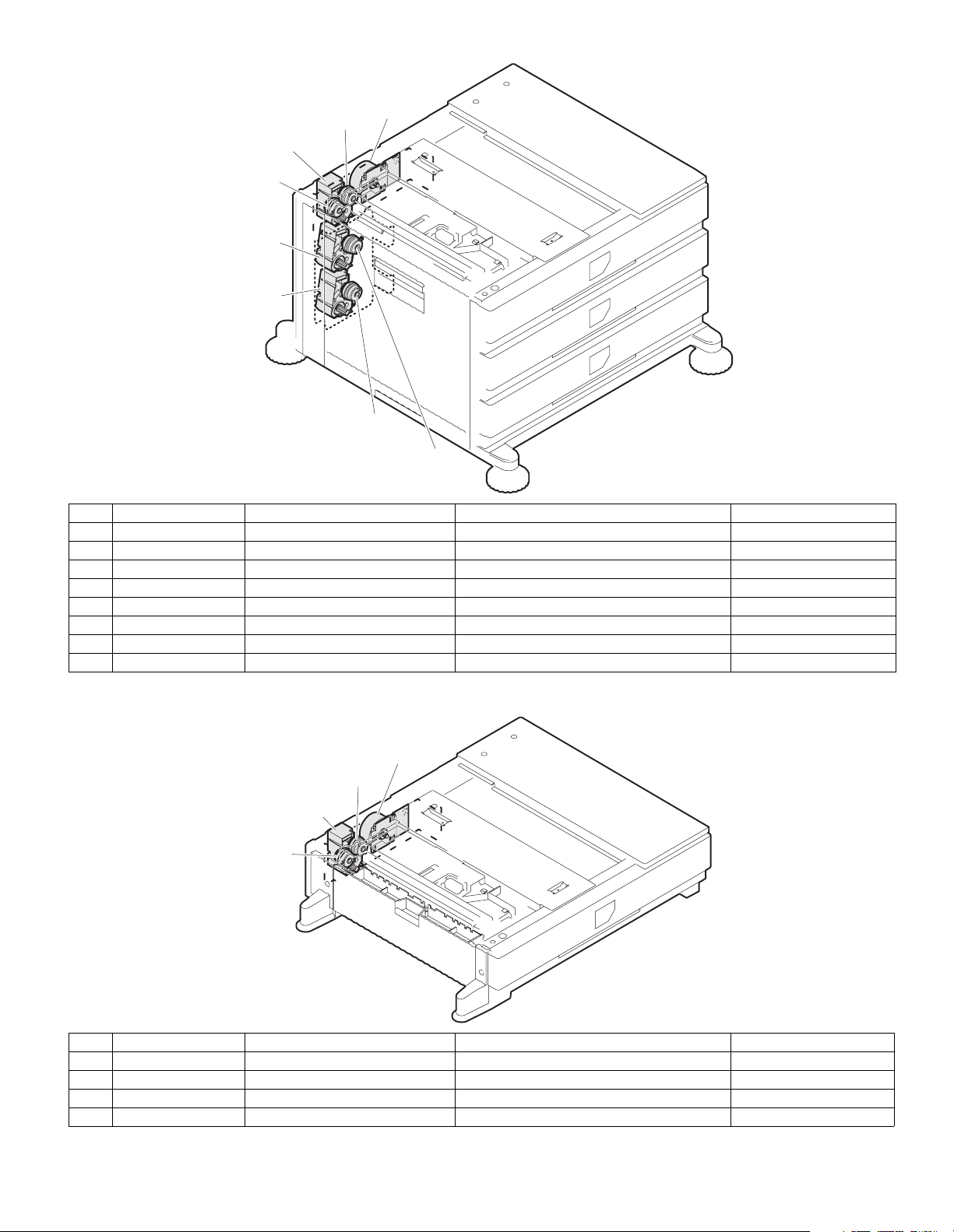
a. Paper feed unit
1) Pull out the multi-purpose tray.
First, pull out the right side of the tray, and then pull out the left side.
b
b
b
u
u
u
u
u
u
u
b
b
b
2) Remove the left door.
2)
1)
u
u
u
,
u
,
u
2)
u
1)
1)
u
u
u
a-5
a
f-2
a-10
a-5
a-9
a-4
a-3
f-4
f-2
f-5
f-2
f-5
f-4
f-3
b-5
b
b-1
f-1
a-6
a-7
a-1
a-2
a-8
a-10
b-6
b-5
b-1
b-2
b-3
b-4
b
c-1
c
c-1
b-1
b-2
b-3
b-4
e-2
e-1
e
e-1
3) Remove the multi-purpose paper feed unit.
7)
8)
6)
3)
6)
4)
5)
AR-D28/D27/MU2 DISASSEMBLY AND ASSEMBLY, MAINTENANCE
7 – 4
Page 23
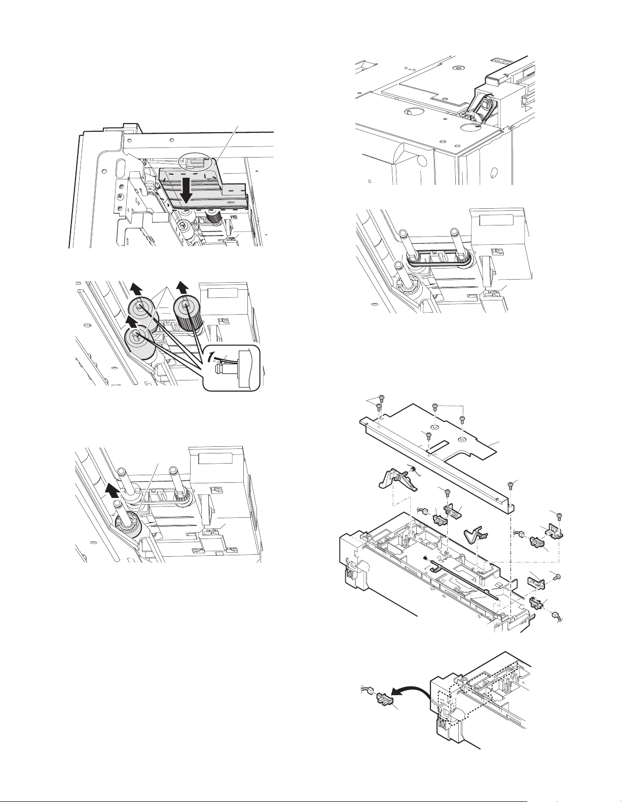
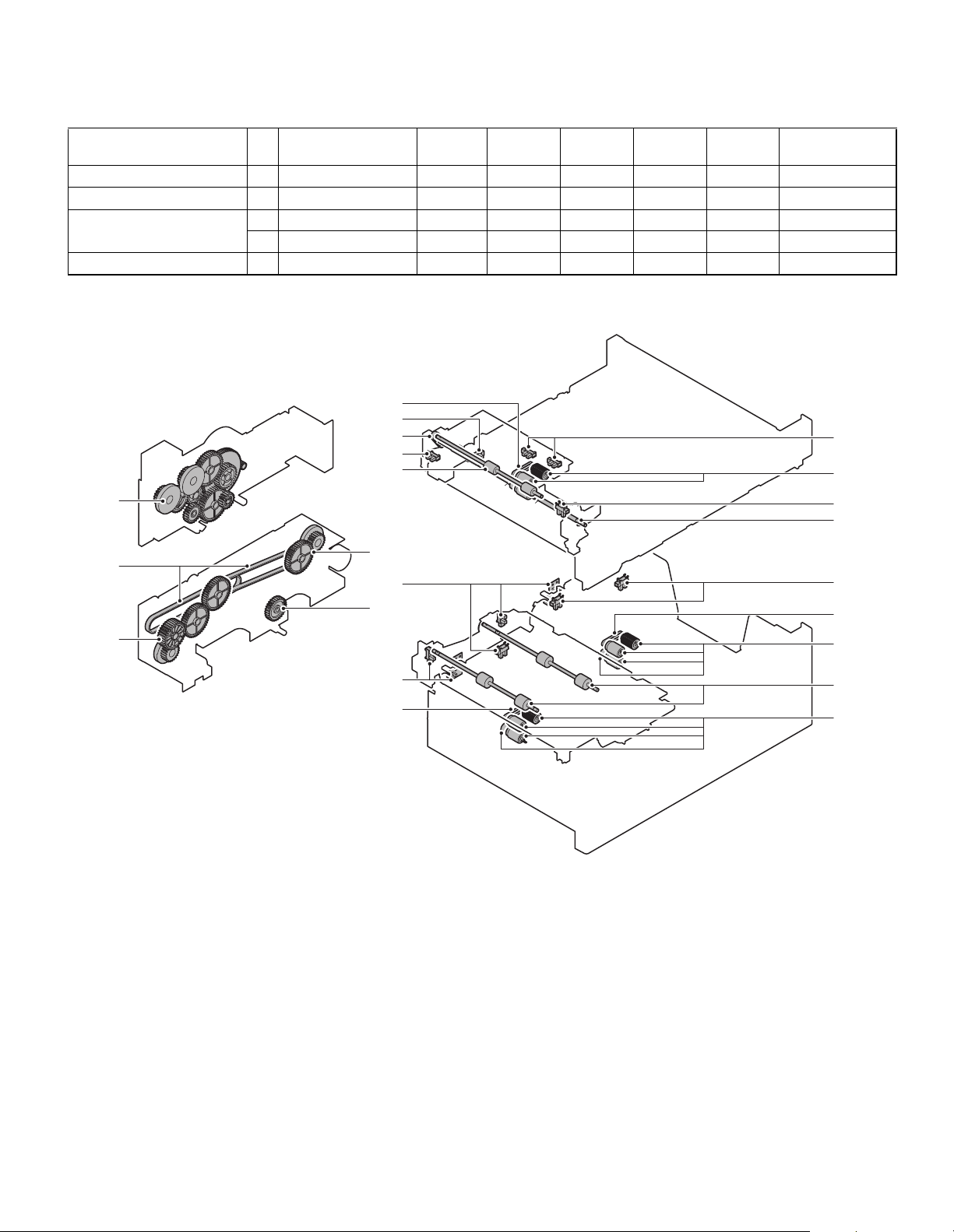
a-1. Pick up roller
a-2. Paper feed roller
a-3. Separate roller
a-4. Torque limiter
1) Pull out the multi-purpose tray.
2) Remove the paper guide.
3) Disengage the roller hook, and remove the roller.
a
a-5. Belts
1) Remove the paper feed unit.
2)
2) Remove the pickup roller and paper feed roller.
3)
When installing the roller, check to ensure that the hook is securely
*
engaged in the groove.
4) After removing the roller, remove the torque limiter.
b
When installing the torque limiter, check to ensure that the pin is
*
fully inserted into the torque limiter groove.
a-6. Upper limit sensor
a-7. Paper empty sensor
a-8. Paper transport sensor
a-9. Side door open/close sensor
1) Remove the paper feed unit.
1)
1)
3)
a
1)
2)
1)
4)
3)
4)
a
4)
3)
a
AR-D28/D27/MU2 DISASSEMBLY AND ASSEMBLY, MAINTENANCE
7 – 5
a
Page 24
a-10. Transfer rollers
1) Remove the paper feed unit.
a
b
b
a
b
a
b. Tandem tray paper feed unit
1) Remove the stopper screw, and pull out the large capacity tray.
2)
b-1. Pick up roller
b-2. Paper feed roller
b-3. Separate roller
b-4. Torque limiter
1) Remove the stopper, and pull out the large capacity tray.
2) Disengage the roller hook, and remove the roller and the torque limiter.
• Tandem tray 1
2)
• Tandem tray 2
a
b
a
1)
2) Remove the left door.
1)
2)
3) Remove the tandem paper feed unit.
2)
2)
2)
b
1)
2)
When installing the roller, check to ensure that the hook is securely
*
a
engaged in the groove.
When installing the torque limiter, check to ensure that the pin is fully
*
inserted into the torque limiter groove.
1)
2)
AR-D28/D27/MU2 DISASSEMBLY AND ASSEMBLY, MAINTENANCE
7 – 6
Page 25
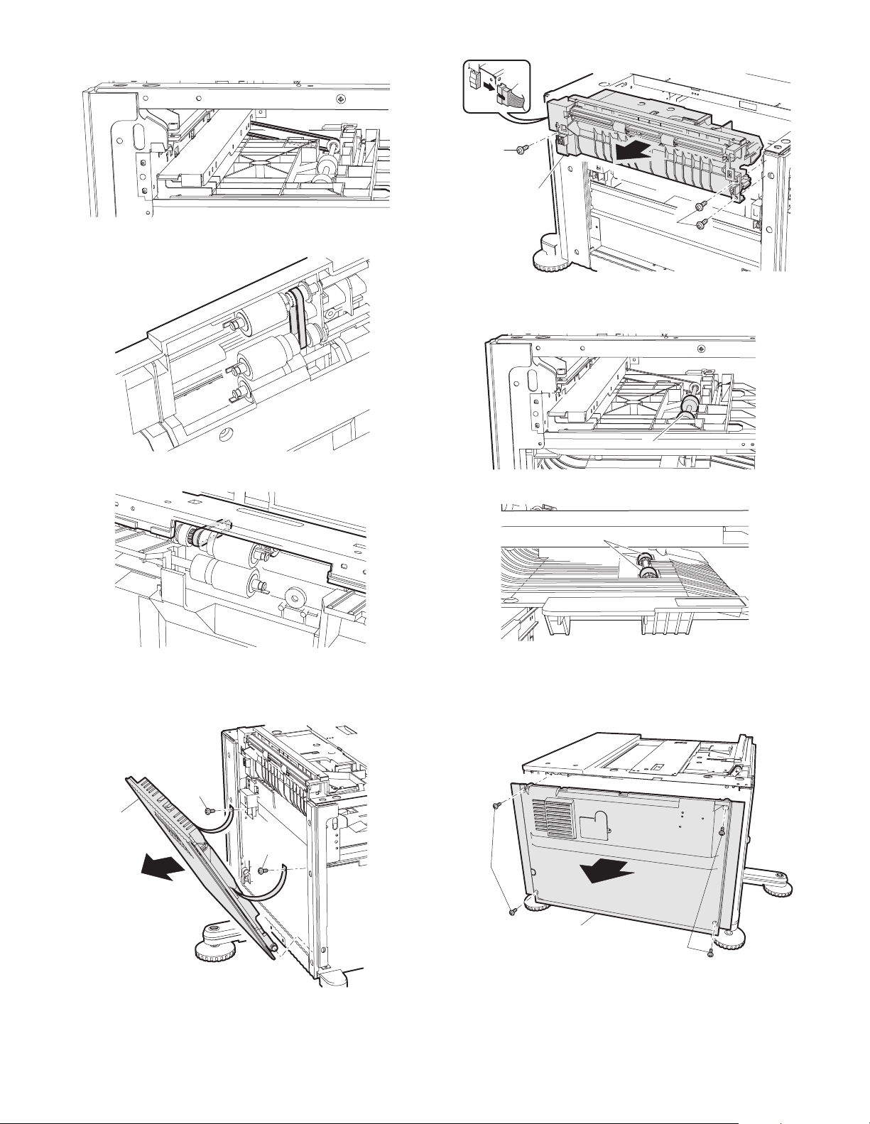
b-5. Belts
1) Remove the stopper, and pull out the large capacity tray.
• Tandem tray 1
2) Remove the transfer unit.
4)
3)
5)
3)
c-1. Transfer roller
1) Pull out the multi-purpose tray.
a
• Tandem tray 2
c. Transfer unit
1) Remove the left door.
2)
b
d. Multi-purpose drive unit
1) Remove the rear cabinet.
1)
1)
1)
AR-D28/D27/MU2 DISASSEMBLY AND ASSEMBLY, MAINTENANCE
7 – 7
2)
1)
Page 26
2) Remove the multi-purpose tray drive section.
f-1. Rear edge size PWB
f-2. Remaining paper quantity sensor
f-3. Control PWB
5)
f-4. Sensor PWB
f-5. Paper transfer sensor
4)
f-6. Tandem tray open/close sensor
1) Remove the rear cabinet.
4)
3)
d-1. Gears
1) Remove the multi-purpose tray drive section.
e. Tandem drive unit
1) Remove the tandem tray drive section.
6)
6)
6)
7)
6)
1)
2)
1)
2) Remove the control PWB and the sensors.
a
a
10)
7)
a
11)
a
8)
7)
10)
a
10)
e-1. Gears
e-2. Belts
2) Remove the tandem tray drive section.
AR-D28/D27/MU2 DISASSEMBLY AND ASSEMBLY, MAINTENANCE
7 – 8
Page 27

(2) AR-D27
MCSPD
DSPD1
MCSS3
MCPWS
DLUM1
DLUM2
DPFCL
DPCL2
DPCL1
MCPCL
DCSS12
DCSS13
PLS PWB1
DCSS22
DCSS23
PLS PWB2
A. MAJOR PARTS AND SIGNAL FUNCTIONS
2nd Control PWB
PHR-9
DPED2
VD(+5V)
VD(+5V)
7S-GND
8
DLUD2
596
S-GND
VD(+5V)
4
3
DPFD3 2
1S-GND
CN-D
VB(+24V)
DPFCL/
VB(+24V)
MCPCL/
+24V(MCLUM) 5
VB(+24V)
GND1(P-GND)
DMM/
DMMCLK/
DMM-T
MCSPD
VD(+5V)
GND2(S-GND)
MCSS1
GND2(S-GND)
MCSS2 17
MCSS3
MCSS4
F-GND
PHDR-20VS-1
CN-E
GND2(S-GND) 1
MCLUD
VD(+5V)
VD(+5V)
GND2(S-GND)
MCPED
GND2(S-GND)
DDRS
VD(+5V)
VD(+5V)
GND2(S-GND)
DPFD1
MCPWS2313
MCPWS
VD(+5V)
N.C.
PHDR-16VS-1
CN-K
DCSS15
DCSS14
DCSS13
DCSS1234
DCSS11
S-GND
PHR-6
CN-J
DLUM1/
N.C.
VB(DLUM1)
S-GND
DSPD1
VD(+5V)
N.C
N.C
PHR-10
CN-H
VB(+24V)
PHR-2
CN-G
VB(+24V)
DPCL1/
PHR-2-R(RED)
CN-I
S-GND
DPFD2
VD(+5V)
DLUD1
VD(+5V) 6
S-GND
DPED1
VD(+5V)
PHR-9-R(RED)
CN-L
DCSS25
DCSS24
DCSS23
DCSS22
DCSS21
S-GND
PHR-6-R(RED)
CN-B
S-GND
DSPD2
VD(+5V)
DLUM2/
CN-A
N.C.
VB(DLUM2)
N.C.
N.C.
N.C.
N.C
N.C
N.C
PHR-12
MCLUM
2
MCLUM/
+24V
1
PHR-2
SMP-02V-NC
SMP-02V-BC
+5V
1
MCLUD
2
3
GND2
179228-3
1
+5V
2
DPFD1
3
GND2
179228-3
+5V
1
DDRS
2
GND2
3
179228-3
+5V
1
MCPED
2
3
GND2
179228-3
2T
MCPWS
1T
MCPWS2
3T
VAREF
18
18
17
17
16
16
15
15
14
14
13
13
6
6
5
5
4
4
1221
SMR-02V-N
212
1
SMR-02V-B
5
DMMCLK/
4
DMM-T
3
DMM/
2
GND1
1
+24V
PHR-5
+5V31
MCSPD2
GND2
179228-3
1N.C.
2
GND2
MCSS1
3
4
MCSS2
MCSS35
MCSS4
6
PHR-6
1
2
PHR-2
1
2
3
179228-3
1
2
SMP-02V-BC SMR-02V-B
1
2
SMP-02V-NC SMR-02V-N
1
2
3
179228-3
1 VD(+5V)
23DPED1
179228-3
1 VD(+5V)
23DPFD2
179228-3
1
2
3
46DCSS22
PHR-6-R(RED)
DLUM1
DLUM2
VD(+5V)
DSPD1
S-GND
1
2
1
2
VD(+5V)
DLUD1
S-GND
S-GND
S-GND
N.C.
GND2
DCSS21
DCSS235
DCSS24
11
11
10
10
9
9
8
8
7
7
6
6
5
SMP-11V-NC
SMP-03V-BC
5
4
4
3
3
2
2
1
1
SMR-11V-N
18
18
17
17
16
16
15
15
14
14
13
13
9
9
8
8
7
7
6
6
5
5
4
4
SMR-18V-BSMP-18V-BC
3
3
22
11
SMR-03V-B
N.C.
1
2 GND2
3
DCSS11
DCSS124
5
DCSS13
6 DCSS14
PHR-6
SMP-18V-NC SMR-18V-N
1
2
3
4
6MCLUM/
7
8
9
10
11
12
13
14
15
16
18
19
20
SRA-21T-4
2
4
5
6
7
8
9
10
11
12
14
15
16
1
2
5
6
1
2
3
4
5
6
7N.C
8
9
10N.C.
1
2DPCL2/
1
2
1
2
3
4S-GND
5
7
8
9
1
2
3
4
5
6
1
2
3
4
5
6
7
8
9
10
11
12
DPFCL
MCPCL
SMP-18V-NC
DDRS
DPCL1
DPCL2
PHR-2
18
18
17
17
16
16
15
15
14 14
13
13
6
6
5
5
4
4 S-GND3
SMR-18V-N
1
VD(+5V)
2
DSPD2
S-GND3
179228-3
1
2
VD(+5V)
1
DLUD2
2
3
S-GND
179228-3
12VD(+5V)
DPED2
3
S-GND
179228-3
VD(+5V)
21DPFD3
179228-3
MCSPD
DSPD1
DSPD2
MPT LD PWB
MCSS1
MCSS3
MCLUD
MCPWS
DCSS11
DCSS13
DLUD1
DCSS21
DCSS23
DLUD2
MCSS2
MCSS4
MCPED
DPFD1
DCSS12
DCSS14
PLS PWB1
DPED1
DPFD2
DCSS22
DCSS24
PLS PWB2
DPED2
DPFD3
DMM
AR-D28/D27/MU2 DISASSEMBLY AND ASSEMBLY, MAINTENANCE
7 – 9
Page 28

Code Name Function Remark
DDRS Side door open/close sensor Side door open/c lose detection
MCSPD MP tray remaining paper quantity sensor MP tray remaining paper quantity detection
MCLUD MP tray upper limit sensor MP tray upper limit detection
MCPED MP tray paper empty sensor MP tray paper empty detection
MDSS1 MP tray rear edge sensor 1 MP tray rear edge size detection In MP tray rear edge size PWB
MCSS2 MP tray rear edge sensor 2 MP tray rear edge size detection In MP tray rear edge size PWB
MCSS3 MP tray rear edge sensor 3 MP tray rear edge size detection In MP tray rear edge size PWB
MCSS4 MP tray rear edge sensor 4 MP tray rear edge size detection In MP tray rear edge size PWB
DCSS11 No. 3 tray rear edge sensor 1 No. 3 tray rear edge size detection In No. 3 tray rear edge size PWB
DCSS12 No. 3 tray rear edge sensor 2 No. 3 tray rear edge size detection In No. 3 tray rear edge size PWB
DCSS13 No. 3 tray rear edge sensor 3 No. 3 tray rear edge size detection In No. 3 tray rear edge size PWB
DCSS14 No. 3 tray rear edge sensor 4 No. 3 tray rear edge size detection In No. 3 tray rear edge size PWB
DCSS21 No. 4 tray rear edge sensor 1 No. 4 tray rear edge size detection In No. 4 tray rear edge size PWB
DCSS22 No. 4 tray rear edge sensor 2 No. 4 tray rear edge size detection In No. 4 tray rear edge size PWB
DCSS23 No. 4 tray rear edge sensor 3 No. 4 tray rear edge size detection In No. 4 tray rear edge size PWB
DCSS24 No. 4 tray rear edge sensor 4 No. 4 tray rear edge size detection In No. 4 tray rear edge size PWB
DPFD1 Desk paper transport sensor 1 Desk paper transport detection
DPED1 N. 3 tray paper empty sensor N. 3 tray paper empty detection
DPFD2 Desk paper transport sensor 2 Desk paper transport detection
DPFD3 Desk paper transport sensor 3 Desk paper transport detection
DPED2 No. 4 tray paper empty sensor No. 4 tray paper empty detection
DLUD2 No. 4 tray upper limit sensor No. 4 tray upper limit detection
MCPWS MP tray width sensor MP tray paper width detection Slide volume
DSPD2 No. 4 tray remaining paper quantity sensor No. 4 tray remaining paper quantity detection
DLUD1 No. 3 tray upper limit sensor No. 3 tray upper limit detection
DSPD1 No. 3 tray remaining paper quantity sensor No. 3 tray remaining paper quantity detection
DLUM2 Desk 2 tray lift-up motor Desk 2 tray lift-up
DLUM1 Desk 1 tray lift-up motor Desk 1 tray lift-up
DPFCL Desk transport clutch Clutch for transport
MCLUM Multi-purpose tray lift-up motor Multi-purpose tray lift-up
MCPCL Multi-purpose paper feed clutch Clutch for paper feed from Multi-purpose tray
DMM 3 tray desk transport motor No. 3 tray desk paper transport
DPCL2 Desk 2 tray paper feed clutch Clutch for paper feed from desk tray 2
DPCL1 Desk 1 tray paper feed clutch Clutch for paper feed from desk tray 1
AR-D28/D27/MU2 DISASSEMBLY AND ASSEMBLY, MAINTENANCE
7 – 10
Page 29

B. MAINTENANCE LIST
(1) MAINTENANCE LIST
Check (Clean, replace, or adjust as necessary.)
u
Clean
F
Replace
b
Adjust , Lubricate
v
Move position
k
Unit name
Paper feed separation section 1 Paper feed rollers
Transport section 2 Transport rollers
Drive section 3 Gears
Other 5 Sensors
1:Replacement reference: Use the counter value of each paper feed port as the replacement reference.
*
Paper feed section pickup roller, paper feed roller: 100K or 1 year
No.
4Belts
Part name
When
calling
uu u u u*
u
u
uu u u u
uu u u u
100K 200K 300K 400K Remark
FFFF
,,,,(Specified position)
4
5
4
5
2
3
1
4
5
4
3
2
4
3
1
3
4
5
3
3
4
3
2
1
1
5
1
5
2
5
1
5
5
1
5
AR-D28/D27/MU2 DISASSEMBLY AND ASSEMBLY, MAINTENANCE
7 – 11
Page 30

(2) MAINTENANCE AND PARTS REPLACEMENT
(List of Replacement Parts)
No. Unit Parts
a Paper feed unit 1 Pick up roller
2 Paper feed roller
3 Separate roller
4 Torque limiter
5Belts
6 Upper limit sensor
7 Paper empty sensor
8 Paper transport sensor
9 Side door open/close sensor
10 Transfer rollers
b Multi-purpose
drive unit
c Drive unit 1 Gears
d Other 1 Rear edge size PWB
1 Gears
2Belts
2 Remaining paper quantity sensor
3 Control PWBs
a. Paper feed unit
1) Pull out the multi-purpose tray.
First, pull out the right side of the tray, and then pull out the left side.
b
b
b
u
u
u
u
u
u
,
u
,
u
2) Remove the left door.
2)
1)
u
u
1)
2)
a-5
a
d-2
a-10
a-5
a-9
a-4
a-3
a-5
d-3
d-2
a-10
a-5
a
a-4
a-3
a-5
a
d-2
a-10
a-5
a-4
a-3
b
d-1
a-6
a-7
a-1
a-2
a-8
a-10
d-1
a-6
a-7
a-1
a-2
a-8
d-1
a-6
a-7
a-1
a-2
a-8
c-2
c-1
c
c-1
3) Remove the paper feed unit.
7)
8)
6)
3)
6)
6)
8)
3)
3)
5)
1)
6)
6)
8)
6)
4)
5)
4)
5)
4)
5)
b-1
c-1
AR-D28/D27/MU2 DISASSEMBLY AND ASSEMBLY, MAINTENANCE
7 – 12
Page 31

a-1. Pick up roller
a-2. Paper feed roller
a-3. Separate roller
a-4. Torque limiter
1) Pull out the multi-purpose tray.
2) Remove the paper guide.
3) Disengage the roller hook, and remove the roller.
a
a-5. Belts
1) Remove the paper feed unit.
2)
2) Remove the pickup roller and paper feed roller.
a-6. Upper limit sensor
a-7. Paper empty sensor
a-8. Paper transport sensor
a-9. Side door open/close sensor
3)
1) Remove the paper feed unit.
1)
1)
When installing the roller, check to ensure that the hook is securely
*
engaged in the groove.
4) After removing the roller, remove the torque limiter.
b
When installing the torque limiter, check to en sure that the pin is fully
*
inserted into the torque limiter groove.
1)
2)
3)
a
a
4)
1)
3)
4)
a
4)
3)
a
AR-D28/D27/MU2 DISASSEMBLY AND ASSEMBLY, MAINTENANCE
7 – 13
Page 32

a-10. Transfer rollers
1) Remove the left door.
2)
b-1. Gears
1) Remove the multi-purpose tray drive section.
1)
1)
c. Drive unit
1) Remove thr rear cabinet.
2) Remove the tandem tray drive section.
a
b
b. Multi-purpose drive unit
1) Remove the rear cabinet.
1)
b
a
a
b
a
10)
9)
9)
9)
11)
10)
c-1. Gears
c-2. Belts
1) Remove the tandem tray drive section.
2)
1)
2) Remove the multi-purpose tray drive section.
4)
3)
5)
4)
AR-D28/D27/MU2 DISASSEMBLY AND ASSEMBLY, MAINTENANCE
7 – 14
Page 33

d-1. Rear edge size PWB
d-2. Remaining paper quantity sensor
d-3. Control PWBs
1) Remove the rear cabinet.
1)
2)
2) Remove the control PWB.
1)
a
a
a
6)
7)
7)
6)
AR-D28/D27/MU2 DISASSEMBLY AND ASSEMBLY, MAINTENANCE
7 – 15
Page 34

(2) AR-MU2
MCM
MCSPD
MCSS3
MCPWS
MCLUM
MCFCL
MCPCL
A. MAJOR PARTS AND SIGNAL FUNCTIONS
18
17
16
15
14
13
9
8
7
5
4
3
212
SMP-03V-BC SMR-03V-B
MCPCL
MCPCL
MCFCL
MCFCL
PHDR-14VS-1
14
13
12
MCPED
MCLUD
MCSPD
MCDRS
MPT PWB
MCPWS
MCPPD
71151036192
8
VAREF
N.C.
MCPWS2
CN-F
CN-A
CN-D
4
+5V
+5V
+5V
+5V
GND2
GND2
GND2
GND2
GND2
GND2
GND2
GND2
MCSS1
MCSS2
MCSS3
MCSS41112
PHDR-12VS-1
24V
MCLUM/
+24V
GND1
MCM/
MCM-T
MCMCLK/
+24V
MCFCL/
+24V
MCPCL/
+5V
PHR-2
PHR-9
CN-E
MCLUM
MCLUM
1
2
3
4
5
6
7
8
9
10
1
2
1
2
3
4
5
6
7
8
9
PHR-6
PHR-5
SMP-02V-BC
1
2
3
4
5
6
1
2
PHR-2
1
2
3
4
5
SRA-21T-4
N.C.
GND2
MCSS1
MCSS2
MCSS3
MCSS4
24V
MCLUM/
+24V
GND1
MCM/
MCM-T
MCMCLK/
11
22
SMR-02V-B
11
22
SMR-02V-NSMP-02V-NC
+5V
18
17
16
15
14
13
8
7
696
5
4
SMR-18V-BSMP-18V-BC
3
1
1
MCLUD
2
3
GND2
+5V
1
MCPPD
2
3
GND2
1
+5V
MCDRS
2
GND23
+5V
1
MCPED
2
GND23
2T
1T
3T
1
+5V
2
MCSPD
3 GND2
MCPWS
MCPWS2
VAREF
MPT LD PWB
MCM
MCM
MCSPD
MCSPD
MCSS1
MCSS3
MCSS3
MCLUD
MCSS2
MCSS4
MCPED
MCDRS
MCPPD
MCPWS
MCPWS
Code Name Function Remark
MCDRS MP door open / close sensor MP left door open / close detection
Control PWB Control PWB Communication with the machine,
MCSPD MP tray remaining paper quantity sensor MP tray remaining paper quantity detection
machine operation control
MCLUD MP tray upper limit sensor MP tray upper limit detection
MDSS1 MP tray rear edge sensor 1 MP tray rear edge size detection In MP tray rear edge size PWB
MCSS2 MP tray rear edge sensor 2 MP tray rear edge size detection In MP tray rear edge size PWB
MCSS3 MP tray rear edge sensor 3 MP tray rear edge size detection In MP tray rear edge size PWB
MCSS4 MP tray rear edge sensor 4 MP tray rear edge size detection In MP tray rear edge size PWB
MCPED MP tray paper empty sensor MP tray paper empty detection
MCPPD MP transport sensor Detection of paper on the path
MCPWS MP tray width sensor MP tray paper width detection Slide volume
MP tray rear
MP tray rear edge size PWB MP tray rear edge size detection
edge size PWB
MCFCL Multi-purpose tray transport clutch Multi-purpose tray transport clutch
MCLUM Multi-purpose tray lift-up motor Multi-purpose tray lift-up
MCPCL Multi-purpose paper feed clutch Clutch for paper feed from Multi-purpose tray
MCM Multi-purpose tray transport motor Multi-purpose tray paper transport
AR-D28/D27/MU2 DISASSEMBLY AND ASSEMBLY, MAINTENANCE
7 – 16
Page 35

B. MAINTENANCE LIST
(1) MAINTENANCE LIST
Check (Clean, replace, or adjust as necessary.)
u
Clean
F
Replace
b
Adjust , Lubricate
v
Move position
k
Unit name
Paper feed separation section 1 Paper feed rollers
Transport section 2 Transport rollers
Drive section 3 Gears
Other 5 Sensors
1:Replacement reference: Use the counter value of each paper feed port as the replacement reference.
*
Paper feed section pickup roller, paper feed roller: 100K or 1 year
No.
4Belts
Part name
When
calling
100K 200K 300K 400K Remark
uu u u u*
u
u
FFFF
,,,,(Specified position)
uu u u u
uu u u u
3
5
4
5
2
1
5
1
4
5
1
(2) MAINTENANCE AND PARTS REPLACEMENT
(List of Replacement Parts)
No. Unit Parts
a Paper feed unit 1 Pick up roller
2 Paper feed roller
3 Separate roller
4 Torque limiter
5Belts
6 Upper limit sensor
7 Paper empty sensor
8 Paper transport sensor
9 Side door open/close sensor
10 Transfer rollers
b Multi-purpose
drive unit
c O t her 1 Rear edge size PWB
1 Gears
2 Remaining paper quantity sensor
b
b
b
u
u
u
u
a-5
a
c-2
a-10
a-5
a-9
a-4
a-3
c-1
a-6
a-7
a-1
a-2
a-8
a-10
u
u
,
u
b
u
b-1
AR-D28/D27/MU2 DISASSEMBLY AND ASSEMBLY, MAINTENANCE
7 – 17
Page 36

a. Paper feed unit
1) Pull out the multi-purpose tray.
First, pull out the right side of the tray, and then pull out the left side.
2)
1)
2) Remove the paper feed unit.
1)
4) After removing the roller, remove the torque limiter.
b
When installing the torque limiter, check to ensure that the pin is fully
*
inserted into the torque limiter groove.
a-5. Belts
1) Remove the paper feed unit.
2)
3)
1)
a-1. Pick up roller
a-2. Paper feed roller
a-3. Separate roller
a-4. Torque limiter
1) Remove the stopper, and pull out the multi-purpose tray.
2) Remove the paper guide.
2)
3) Disengage the roller hook, and remove the roller.
a
2) Remove the pickup roller and paper feed roller.
3)
When installing the roller, check to ensure that the hook is securely
*
engaged in the groove.
AR-D28/D27/MU2 DISASSEMBLY AND ASSEMBLY, MAINTENANCE
7 – 18
Page 37

a-6. Upper limit sensor
a-7. Paper empty sensor
a-8. Paper transport sensor
a-9. Side door open/close sensor
1)
b. Multi-purpose drive unit
1) Remove the rear cabinet.
1)
1)
2)
3)
a
4)
1)
3)
4)
a
4)
3)
a
1)
2) Remove the tray drive section.
2)
1)
4)
3)
5)
4)
b-1. Gears
1) Remove the tray drive section.
a
a-10. Transfer rollers
1) Remove the paper feed unit.
a
b
b
c-1. Rear edge size PWB
c-1. Remaining paper quantity sensor
1) Pull out the multi-purpose tray.
b
a
AR-D28/D27/MU2 DISASSEMBLY AND ASSEMBLY, MAINTENANCE
7 – 19
a
4)
5)
Page 38

[8] BLOCK DIAGRAM, WIRING DIAGRAM,CIRCUIT DIAGRAM, PARTS ARRANGEMENT
A. BLOCK DIAGRAM
B
B
B
D
D
D
D
1/1
12345678
12345678
12345678
12345678
C
C
C
C
B
A
T
I
UN
K
S
E
D
EM
ND
TA
24V
TPCL1/
24V
TPCL2/
24V
MCPCL/
OR
ST
NSI
A
R
T
ARRAY
P-GND
24V
TPFCL/
NSISTOR
A
TR
P-GND
TLUM2/
TLUM1/
R
ANSISTO
TR
P-GND
MCLUM/
OR
SIST
TRAN
R
O
T
S
I
L
NS
A
GITA
TR
DI
L
A
NSISTOR
RA
T
DIGIT
24V/P-GND
TMM
TMM/
TMM-T
TMMCLK/
OR
TOR
S
ST
L
L
NSI
TA
ITA
GI
G
TRANS I
DI
TRA
DI
R
TO
S
NSI
TAL
A
IGITAL
IGI
R
D
T
D
R
O
T
SIS
N
A
R
T
5V/S-GND
TSPD1
R
O
ST
I
S
N
A
DIGITALTR
5V/S-GND
5V/S-GND
5V/S-GND
TSPD2
TLUD1
TLUD2
F
5V/S-GND
5V/S-GND
5V/S-GND
TPED2
TTSD
TPED1
5V/S-GND
5V/S-GND
5V/S-GND
TPFD2
TPFD1
TPFD3
5V/S-GND
5V/S-GND
5V/S-GND
TDRS
MCLUD
MCPED
S-GND
S-GND
MCSS2
MCSS1
S-GND
S-GND
MCSS3
MCSS4
5V/S-GND
5V/S-GND
MCPWS
MCSPD
R
O
ST
L
NSI
TA
DIGI
TRA
RELAY
DCPS
+5V
+24V
UNIT
S-GND
P-GND
21
21
21
21
3
3
3
3
644
8/ 3
H
CPU
WB
P
rol
ont
C
N
A
T
R
O
T
S
L
NSI
ITA
A
TR
DIG
AR-D28
DHRY1
DHRY2
/
/
K
K
S
S
D
D-
D- D
X
X
R
T
K
K
S
DS
R
R- DSK
T
S
D
D
D
N
S- D
G
E
R
F-
TRC-DSK/
OPTIONALY
DH PWB
AC N
24V
L
AC
AC L
L
AC
DH SW
R
SCN UN
PRIN TE
B
B
B
D
D
D
D
AR-D28/D27/MU2 BLOCK DIAGRAM, WIRING DIAGRAM,CIRCUIT DIAGRAM, PARTS ARRANGEMENT
C
C
C
C
8 – 1
B
SCN UN
87654
87654
87654
87654
A A
A A
A A
A
Page 39

B
B
B
D
D
D
D
1/1
12345678
12345678
12345678
12345678
C
C
C
C
B
A
24V
DPCL1/
24V
DPCL2/
24V
24V
MCPCL/
ARRAY
TRANSISTOR
P-GND
DPFCL/
DLUM1/
TRANSISTOR
P-GND
P-GND
DLUM2/
MCLUM/
TRANSISTOR
TRANSISTOR
24V/P-GND
DMM
DMM/
DMMCLK/
TRANSISTOR
DIGITAL
DIGITAL
TRANSISTOR
DMM-T
5V/S-GND
5V/S-GND
5V/S-GND
DSPD1
DSPD2
DLUD1
5V/S-GND
5V/S-GND
5V/S-GND
DLUD2
DPED1
5V/S-GND
DPFD2
DPED2
5V/S-GND
5V/S-GND
5V/S-GND
DDRS
DPFD1
DPFD3
5V/S-GND
S-GND
5V/S-GND
MCSS1
MCPED
MCLUD
S-GND
S-GND
MCSS2
MCSS3
S-GND
5V/S-GND
MCSS4
MCSPD
S-GND
5V/S-GND
MCPWS
DCSS11
S-GND
S-GND
DCSS13
DCSS12
S-GND
DCSS14
S-GND
S-GND
DCSS22
DCSS21
S-GND
S-GND
DCSS23
H8/3644
CPU
DCSS24
+5V
DCPS
RELAY
+24V
UNIT
S-GND
21
21
21
21
P-GND
3
3
3
3
2ND DESK UNIT
AR-D27
PRINTER
D
D
D
D
DIGITAL
TRANSISTOR
TXD-DSK
TRANSISTOR
DIGITAL
RXD-DSK
DIGITAL
TRANSISTOR
DTR-DSK/
DIGITAL
TRANSISTOR
RES-DSK
DSR-DSK/
DIGITAL
TRANSISTOR
TRC-DSK/
F-GND
C
C
C
C
F
AC N
AC L
B
B
B
B
TRANSISTOR
DIGITAL
DHRY1
DH PWB
AC N
AC L
OPTIONALY
DH MPF
DIGITAL
TRANSISTOR
DHRY2
AC L
AC N
DH DESK
24V
AC L
AC N
SCN UN
SCN UN
A A
A A
A A
A
3T Control PWB
AC LAC L
DH SW
87654
87654
87654
87654
AR-D28/D27/MU2 BLOCK DIAGRAM, WIRING DIAGRAM,CIRCUIT DIAGRAM, PARTS ARRANGEMENT
8 – 2
Page 40

B
B
B
S-GND
CSS1
M
S-GND
S2
S
C
M
C
C
C
C
S-GND
3
S
MCS
S-GND
4
CSS
M
VAREF
WS
CP
M
VB
/
CPCL
M
VB
FCL/
MC
D
D
D
D
1/1
12345678
12345678
12345678
12345678
VD/S-GND
VD/S-GND
CSPDMC
MCLUD
M
VD/S-GND
S-GND
D
T
E
S
PE
C
M
VD/S-GND
VD/S-GND
CPPD
M
MCDRS
P-GND
/
M
U
L
MC
B
VB/P-GND
MCM
Y
AL
N
A
DH MPF
21
21
21
21
CS UNI T
TI
MAL
OPTIO
/
-T
MCM
K
L
C
CM
M
/
CM
M
VB
/
/
S
MCDR
CPPD
M
D
D
E
CLUD
M
CSET
M
MCP
MCSP
3
1
MCSS
4
S
SS
MCSS2
MCS
MC
S
PW
C
M
L
C
CP
M
/
L
M
/
C
F
CLU
C
DCPR
M
M
AC N
L
C
A
DH-SW
PWB
H
D
3
3
3
3
Multi PWB
)
ND
G
CSS3MCSS
M
S-
4
(
GND1
S
D
R
UD
L
D
CPP
MC
MC
M
+5V1(VD)
MCSPD
1
T
E
S
S2
S
S
MCPED
C
M
MCS
MC
EF
R
VA
WS
CP
M
)
B
/
V
L/
M/
/
C
R
LU
F
PCL
4V2(
C
2
+
M
P
C
C
C
M
M
D
/
-GND)
K
P
-T
M
MC
GND2(
N
M/
L
C
MCMCL
C
M
AC
A
AR-MU2
NTER
I
R
P
87654
87654
87654
87654
B
B
B
D
D
D
D
AR-D28/D27/MU2 BLOCK DIAGRAM, WIRING DIAGRAM,CIRCUIT DIAGRAM, PARTS ARRANGEMENT
C
C
C
C
8 – 3
B
A A
A A
A A
A
Page 41

B. WIRING DIAGRAM
D
D
D
D
1/1
12345678
12345678
12345678
12345678
TSPD2
TAN Sensor
PWB
VD(+5V)
S-GND
TLUD2
TPED23S-GND
VD(+5V)
179228-3
VD(+5VR)
5
1
2
4
PHR-5
3
2 TSPD2
1
VD(+5V)
1
TSPD1TSPD1
2
S-GND
3
179228-3
1
2
3
4
5
6N
7
8
9
10
11
12
PHR-12
TLUM2
P-GND
TLUM2
1
2
LIFT MOTOR UNIT
PHR-2
CN-B
S-GND
TSPD1
VD(+5V)
P-GND
TLUM2
.
C.
S-GND
TPFD3
VD(+5V)
S-GND
TTSD
VD(+5V)
VD(+5V)
1
TPFD3
TPFD3
2
S-GND
3
179228-3
CN-C
2
1
1
2
1
2
TPCL2/
VB(+24V)
TTSD
VD(+5V)
TTSD
S-GND
2
1
3
2
1
3
SMR-02V-B
SMP-02V-BC
PHR-2
C
C
C
C
SMR-03V-N
SMP-03V-NC
1
2
2
1
2
1
(RED)
VB(+24V)
TPCL1/
CN-G
SMR-02V-N
SMP-02V-NC
PHR-2-R(RED)
TPCL2
B
B
B
B
DH SW
TPFD2
TAN Sensor
TPCL1
TPFD2
S-GND
VD(+5V)
TLUD1
TPED1
2
1
3
1
2
179228-3
3
456
7
2
8
9
1
PHR-9
VD(+5V)
N.C
TLUD1
TPFD2
VD(+5V)
S-GND
S-GND
VD(+5VR)
CN-I
TPED1
PWB
S-GND1VD(+5VR)
VD(+5V)
4
5
3
PHR-5
TLUM1
TLUM1
P-GND
2
LIFT MOTOR UNIT
PHR-2
45678
1
2
3
CN-J
N.C.
TLUM1
P-GND
N.C.
3
1
2
2
1
3
1
B2P3-VH
AC L2AC N
AC N1
N.C
CN-E
CN-B
VB(+24V)
DHRY1
DHRY2
2
3
9
10
1
2
PHR-10
CN-N
N.C.
N.C.
N.C.
N.C.
N.C.
N.C.
DHRY23VB(+24V)
DHRY1
PHR-3
PHR-3
AC L
CN-D
N.C
CN-A
AC L
1
B2P3-VH-R
AC N
N.C
2
3
B2P3-VH
AC L
CN-F
CN-C
AC L
1
3
N.C
AC L
DH PWB
AC N
N.C
2
3
B2P3-VH-BL
(OPTION)
B2P3-VH
A
A
21
21
21
21
3
3
3
3
TAN Control PWB
2
1
PHR-2
MCLUM
P-GND
MCLUM
LIFT MOTOR UNIT
2
2
MCPCL
SMP-02V-NC
1
1
SMR-02V-N
11
11
2
2
TPFCL
10
9
10
SMP-02V-BC
1
1
SMR-02V-B
CN-A
TSPD2
S-GND
1
23456
SMP-11V-NC
4
2
1
5
789
6
4
531
2
3
7
6
8
SMR-11V-N
2
1
3
2
4
5
1
PHR-5
TMM/
+24V
GND1
TMM-T
TMMCLK/
+5V
MCSPD
TMM
MCSPD
VD(+5V)
S-GND
3
179228-3
GND2
TLUD2
N.C
VD(+5VR)
7
TPED2
8
VD(+5V)
9
1N.C.
CN-D
VB(+24V)
PHR-9
1
4
2
5
GND2
MCSS23MCSS3
MCSS1
MPT LD PWB
TPFCL/
234
6
MCSS4
VB(+24V)
MCPCL/
PHR-6
GND1(P-GND)
MCLUM
567
GND1(P-GND)
VB(+24V)
TMM/
91011
8
TMM-T
TMMCLK/
VD(+5V)
MCSS1
MCSS3
MCSPD
F-GND
GND2(S-GND)
MCSS2
GND2(S-GND)
MCSS4
141516
171819
20
12
PHDR-20VS-1
13
F
SRA-21T-4
15+5V
16
18
17
14
15
17214
18
16
1
2
1
3
2
179228-3
TPFD1
+5V
MCLUD
GND2
MCLUD
PAPER FEEDING UNIT
TPFD1
CN-E
GND2(S-GND)
1
13
13
3
179228-3
GND2
MCLUD
234
VD(+5V)
VD(+5V)
9
9
1
+5V
MCPED
TDRS
GND2(S-GND)
GND2(S-GND)
6
7
8
5
8
7
8
7
3
179228-3
GND2
TDRS
TDRS
VD(+5V)
9
VD(+5V)
10
6
6
1
+5V
MCPWS
TPFD1
GND2(S-GND)
MCPWS2
11
12
13
141516
4
5
4
5
SMR-18V-B SMP-18V-BC
3
2
179228-3
MCPED
GND2
MCPED
N.C.
VD(+5V)
PHDR-16VS-1
321
321
2T
1T
MCPWS
MCPWS2
MPT VR UN
3T
VAREF
CN-M
SMP-03V-BCSMR-03V-B
TXD
TEST
S-GND
11
PHR-11
9
10
3
5
4
RES_FIN1
RXD_FIN1/2GND2
DTR_FIN1/
DSR_FIN1/
6
7
TXD_FIN2
8
9
10
DSR_FIN2/
RXD_FIN2/
DTR_FIN2/
CN-F
+24V(VB)
123
12GND2
11
RES_FIN2
P-GND
1
1
+24V(VB)
13
RXD_DSK
TXD_DSK
DTR-DSK/
DSR-DSK/
S-GND
+5V(VD)
TXD-DSK
GND2
RXD-DSK/
456
789
2345678910
6
7
5
8
3VD(+5V)
GND24DSR-DSK/
P-GND 2
DTR-DSK/
RXD-DSK/
TXD-DSK
S-GND
181722
162119
201415
FGS_FIN/
DTR_DSK
DSR_DSK
TRC_DSK/
(N.C)
RES_DSK
TRC-DSK/
RES-DSK
10
11
9
10
RES-DSK
(N.C)
(N.C)
PHDR-12VS-1
12 N.C.
11
SMR-11V-B
11
TRC-DSK
OPTION
POWERSUPPLY I/F UN
ELP-04NV
123
2
4
1
4
1
1
3
22
ELR-04V
1
5
4
2
3
GND
GND
GND
+24V4
+5V2
FUSE PWB
DCPS
ELR-02VF
ELP-02V
MAIN UN
SCN UN
ER
G
TI
87654
87654
87654
87654
/RESMD/RXD
/TXD
CLOCK OUT
+5V(VD)
FVpp
RES
6
5
8
4
7
2
3
1
PADP-22V-1-R
1
B22B-PADRS
TXD_FIN1
CN11
AR-D28
A A
B
B
B
D
D
D
D
C
C
C
C
B
A
A A
A
AR-D28/D27/MU2 BLOCK DIAGRAM, WIRING DIAGRAM,CIRCUIT DIAGRAM, PARTS ARRANGEMENT
8 – 4
Page 42

B
B
B
D
D
D
D
C
C
C
C
B
A
A
A
A
1/1
12
12
12
12
(OPTION FOR JAPAN)
(OPTION FOR JAPAN)
DH SW
DH MPF
DH DESK
ELP-02
ELP-02
2
1
2
1
1
2
1
ELR-02
ELR-02VF
(JAPAN ONLY)
2
1
2
3
1
B2P3-VH
AC N
AC L
DPFD3
2 DPFD3
5
S-GND3
179228-3
SMR-18V-N
4
4
SMP-18V-NC
DSPD2
DSPD2
VD(+5V)
2
1
S-GND3
PHR-12
179228-3
CN-B
1
2
3
4
5
6
7
8
9
10
11
12
S-GND
DSPD2
VD(+5V)
P-GND
N.C.
DLUM2
N.C.
N.C.
N.C.
N.C
N.C
N.C
DLUM2
1
2
LIFT UP MOTOR UNIT
PHR-2
DPCL2
SMR-02V-BPHR-2
1
1
SMP-02V-BC
1
22 2
CN-H
DPCL2/
VB(+24V)
DPCL1
1
CN-G
VB(+24V)
SMR-02V-N
2211
SMP-02V-NC
2
PHR-2-R(RED)
DPCL1/
DPED1
S-GND
3
161718
179228-3
CN-I
1
S-GND
VD(+5V)
1
15
151617
2
DPFD2
DPED1
2
3
VD(+5V)
S-GND
3
179228-3
4
5
S-GND3DLUD1
VD(+5V)
1 VD(+5V)
61314
61314
7
S-GND
DPFD22
DPFD2
5
5
8
DPED1
S-GND
3
4
4
9
VD(+5V)
DLUD1
VD(+5V)
DLUD1
1
2
PAPER FEEDING UNIT
18
179228-3
SMR-18V-N
SMP-18V-NC
PHR-9-R(RED)
CN-J
DLUM1
LIFT UP MOTOR UNIT
2
1
PHR-2
3
412
5
1
DLUM1
S-GND
P-GND
DSPD1
N.C.
6
VD(+5V)
VD(+5V)
1
7
N.C
DSPD1
DSPD1
2
8
N.C
S-GND
9
N.C
179228-3
10N.C.
PHR-10
CN-K
N.C.
1
DCSS15
PLS-PWB1
GND2
DCSS11
3
2
261
3
4
DCSS14
DCSS13
DCSS12
DCSS12
4
5
DCSS11
DCSS13
5
6
S-GND
DCSS14
6
PHR-6
PHR-6
CN-L
1
DCSS25
N.C.
2
DCSS24
PLS-PWB2
GND2
DCSS22
DCSS21
3
2
4
3
5
4
DCSS23
DCSS21
DCSS22
DPED2
DLUD2
DPED2
DLUD2
VD(+5V)
S-GND
179228-3
VD(+5V)
1
3
2
1
179228-3
13
6
15
14
6
14
13
VD(+5V)
S-GND
3
2
1
PAPER FEEDING UNIT
16
17
3
3
3
3
4
4
4
4
18
18
16515
17
DCSS23
DCSS24
6
5
6
PHR-6-R(RED)
S-GND
PHR-6-R(RED)
N.C
CN-E
VB(+24V) 2
2
1
CN-N
VB(+24V)
CN-B
DHRY1
1
2
DHRY1
DHRY2
3
DHRY2
3
B2P3-VH-R
AC N
AC L
N.C
CN-D
CN-A
N.C
AC N
AC L
PHR-332
B2P3-VH
1
2
3
PHR-3
3
N.C 2
AC L
AC L 1
CN-F
DH PWB
CN-C
AC N
AC L
N.C
1
3
B2P3-VH-BL
(OPTION)
B2P3-VH
1
1
1
1
2
2
2
2
3
3
3
3
4
4
4
4
GND1(P-GND)
VD(+5V)
VD(+5V)
DPFD32
DLUD2
CN-A
5
4
1 S-GND
6
5678
5678
5678
5678
SMP-11V-NC
2
5109
1
3
8
7
4
6
11
10
5
2
7
493
1
6
8
11
SMR-11V-N
SMP-02V-BC
SMP-02V-NCSMR-02V-N
1
2
221
1
1
2
SMR-02V-B
3
1
123
4
DPFCL/
5
DMM-T
DMMCLK/
DMM
179228-3
PHR-5
DMM/
GND1
+24V
MCSPD 2
+5V
GND2
MCSPD
2
1
PHR-2
MCLUM
P-GND
MCLUM
LIFT MOTOR UNIT
MCPCL/
VB(+24V)
MCPCL/
VB(+24V)
DMMCLK/16DMM/
MCSS1
GND2(S-GND)
DMM-T
CN-D
5
MCSS23MCSS3
DPFCL/
216
6
PHR-6
MCSS44MCSS1
GND1(P-GND)
MCLUM
4
5133
VB(+24V)
7
S-GND3S-GND
DPED2
VD(+5V)
9
8
7
PHR-9
1N.C.
2
GND2
MCSS2
GND2(S-GND)
MCSPD
VD(+5V)
10
9
14
11
15
12
PAPER FEEDING UNIT
MPT LD PWB
MCSS3
18817
18
18
123
+5V
MCSS4
19
17
17
MCLUD
MCLUD
F-GND
20
16
16
GND2
PHDR-20VS-1
SRA-21T-4
179228-3
+5V
CN-E
2
DPFD1
DPFD1
GND2(S-GND)1
GND2(S-GND)
VD(+5V)
VD(+5V)
MCLUD
131415
311
179228-3
GND2
DPFD1
VD(+5V)
MCPWS
MCPED
MCPWS2
VD(+5V)
GND2(S-GND)
GND2(S-GND)
DDRS
3
13
5
12
4
7
151611141028
9
6
SMP-18V-BC179228-3
456
7
8
9
456789131415
SMR-18V-B
3
2
2
3
1
179228-3
DDRSDDRS
+5V
GND2
+5V
GND2
MCPED
MCPED
N.C.
PHDR-16VS-1
SMP-03V-BC
3
1
22
1
3
SMR-03V-B
3T
2T
1T
VAREF
MCPWS
MCPWS2
MPT VR UN
MD
CN-M
1
/RXD
/RES
2
3
+5V(VD)
CLOCK OUT
/TXD
FVpp
7
4
PADP-22V-1-R
3
1
B22B-PADRS
RXD_FIN1/2GND2
DTR_FIN1/
TXD_FIN1
CN11
TEST
RES
TXD
S-GND
8
10
11
PHR-11
956
8
11
9
7
10
5
6
TXD_FIN2
RES_FIN2
RXD_FIN2/
RES_FIN1
DSR_FIN1/4DTR_FIN2/
DSR_FIN2/
+24V(VB)
CN-F
1
123
1
+24V(VB)
TXD_DSK
VD(+5V)VD(+5V)
P-GND
2
3
3
P-GND 2
141512GND218172213
RXD_DSK
DTR_DSK
S-GND
GND2
5
4
45678
5
4
GND2
S-GND
162119
DSR_DSK
RES_DSK
TXD-DSK
RXD-DSK/
6
7
6
7
TXD-DSK
RXD-DSK/
TRC_DSK/
FGS_FIN/
DTR-DSK/
DSR-DSK/
8
9
91011
8DTR-DSK/
9
DSR-DSK/
20
(N.C)
(N.C)
TRC-DSK/
RES-DSK
10
11
11
10
RES-DSK
TRC-DSK
(N.C)
[STANDARD EQUIPMENT(JAPAN ONLY)]
12 N.C.
PHDR-12VS-1
SMR-11V-B
OPTION
POWERSUPPLY I/F UN
ELP-04NV
ELR-02VF
123
4
1
2
2
4
1
2
3
1
ELR-04V
ELP-02V
3
2
5
4
1
+24V4
+5V2
MAIN UN
FUSE PWB
SCN UN
ER
G
I
T
GND
GND
GND
5
5
5
5
76
76
76
76
8
8
8
8
VD(+5V)
AR-D27
B
B
B
D
D
D
D
C
C
C
C
B
A
A
A
A
AR-D28/D27/MU2 BLOCK DIAGRAM, WIRING DIAGRAM,CIRCUIT DIAGRAM, PARTS ARRANGEMENT
8 – 5
Page 43

B
B
B
C
C
C
VAREF
3T
+5V
1
MCSPD
MCSPD
2
GND2
3
C
D
D
D
D
1/1
12
12
12
12
MCLUD
MCPPD
GND2
GND2
MCPPD
+5V
+5V
MCLUD
1
1
2
2
3
3
MCPED
MCDRS
GND2
MCPED
MCDRS
+5V
GND2
+5V
2
3
3
1
1
2
MPT VR UN
MCPWS
MCPWS2
2T
1T
B
A
A
A
A
(OPTION FOR JAPAN)
F
P
M
DH
ELP-02
1
2
1
2
ELR-02VF
2N.C
B2P3-VH
L1
AC
AC N 3
N-C
C
B
A
-
-
L
N
N
C
C
AC
N.C
DCPR/
+24V2
AC N
N.C
3
1
2
1
3
PHR-3
DH-SW
B
W
P
H
B2P3-VH
D
(OPTION FOR JAPAN)
21
21
21
21
3
3
3
3
5
11
MCSS3
VAREF
2
6
12
MCSS4
+24V
3
PHR-6
PHDR-12VS-1
MCPPD
GND2
MCDRS
GND1
7
6
5
MCLUM
GND1
MCLUM
2
1
PHR-2
LIFT MOTOR UNIT
2
PHR-2
A
-
MCLUM1GND1
N
C
MCSS1
MCSS2
MCPED
MCLUD
MCPWS
10
9
11
8
12
MCSS3
13
MCSS4
14
D
N
C
MCSET4MCM-T
MCFCL/
MCSPD
MCPCL/
18
17
16
15
+24V
2
1
254
1
+24V
GND1
MCLUM/
19
20
MCM
MCM-T
MCM/4GND1
3
3
MCM-T
MCM/
MCM/
MCMCLK/
22
21
MCMCLK/
5
PHR-5
6
+24V
MCMCLK/
N.C
DCPR/
24
23
789
PHR-9
+24V
MCFCL/
MCPCL/
PHDR-24VS-1
122
B
N
C
MCFCL
SMR-02V-B
SMP-02V-BC
DCPR/
+24V
1
2
3
N.C
MCPCL
11221
PHR-3
SMR-02V-NSMP-02V-NC
MPT LD PWB
GND2
MCSS24MCSS33MCSS4
MCSS1
N.C.
1
2
SMR-18V-B
5
8
9
7
6
15
14
16
18
17
PAPER FEEDING UNIT
3
3
3
3
456
456
456
456
13
14
13
15
17
16
18
4
4
7
8
6
9
5
SMP-18V-BC
2
3
1
2
3
1
SMP-03V-BC SMR-03V-B
SRA-21T-4
647
1
2
5
3
9
10
E
CN-
+5V
1
+5V
2
+5V
3
+5V
4
+5V
5
VAREF
6
N.C.
7
MCPWS2
8
MCPWS
9
MCPPD
10
MCDRS
11
MCPED
12
MCLUD
13
14
MCSPD
PHDR-14VS-1
-F
GND2
N
C
T
MP
GND1
GND2
B
W
P
GND2
GND2
GND2
GND2
GND2
MCSS28MCSS1
+5V
C
N
1
C
7
7
7
7
8
8
8
8
AR-MU2
6
11
3
1
7
8
10
5
9
TRC-DSK
GND24DSR-DSK/
S-GND
RES-DSK
RXD-DSK/
P-GND2TXD-DSK
VD(+5V)
+24V(VB)
DTR-DSK/
OPTION
POWERSUPPLY I/F UN
ELR-02VF
ELP-04NV
4
3
1
1
2
2
1
2
3
4
2
1
ELP-02V
ELR-04V
8
2
1
9
7
6
5
4
3
B24B-PADES PADP-24V-1-E
0
1
GND1
GND2
MCLUD
MCPED
+24V
MCDRS
+5V
VAREF
MCPPD
N
C
D
D
D
D
C
C
C
C
10
11
MCSS1
MCPWS
12
MCSS2
13
MCSS3
14
MCSS4
15
MCSPD
16
MCSET
181920
17
MCFCL/
MCPCL/
MCLUM/
MCM-T
21
22
MCMCLK/
MCM/
PADP-22V-1-R
24
23
1
B22B-PADRS
1
e/?
DCPR/
TXD_FIN1
CN1
B
B
B
B
3
4
2
RXD_FIN1/
DSR_FIN1/
DTR_FIN1/
6
5
GND2
RES_FIN1
8
7
RXD_FIN2/
TXD_FIN2
10
11
9
DTR_FIN2/
RES_FIN2
DSR_FIN2/
12
13
TXD_DSK
GND2
15
14
RXD_DSK
DTR_DSK
17
16
18
DSR_DSK
TRC_DSK/
RES_DSK
20
19
FGS_FIN/
(N.C)
21
22
(N.C)
(N.C)
5
1
4
3
2
MAIN UN
GND
B
GND
GND
+5V2
+24V4
W
P
ER
S
E
G
P
C
TI
D
FUS
A
A
A
A
87654
87654
87654
87654
AR-D28/D27/MU2 BLOCK DIAGRAM, WIRING DIAGRAM,CIRCUIT DIAGRAM, PARTS ARRANGEMENT
8 – 6
Page 44

C. CIRCUIT DIAGRAM
D
D
D
D
D1FL20U
D108
1SS133
TD62003AP
D105
MCLUM
TLUM1(DLUM1)
DSR-DSK
JP104
DSM1D
D107
Q103
ICP101
VB
TLUD2(DLUD2)
TLUD1(DLUD1)
MCLUD
CNB-5
TLUM2
DLUM2
2SB1240
MCSPD
DHRY2/
CND-4
CND-2
CNC-2,H-2
CNG-2
1/2
12345678
12345678
12345678
12345678
MCPCL/
TPFCL/ (DPFCL/)
TPCL2/(DPCL2/)
TPCL1/ (DPCL1/)
VB
9
10
O116O215O314O413O512O611O7
COM
IC102
I11I22I33I44I55I66I77GND
8
DPCL2
TLUM2(DLUM2)
MCPCL
TPCL1(DPCL2)
TPCL2(DPCL1)
TPFCL(DPFCL)
CNB-6
R153
ICP-N20
TRC-DSK
R159
2.4kJ1/4W
D109
Q105
2.4kJ1/4W
DTR208
1SS133
R156
17
18
19
20
21
22
23
24
25
26
27
28
29
30
31
32
M
2SB1240
3
R152
2.4kJ1/2W
I
2
2.4kJ1/2W
G1O
P60
P61
P62
P63
P64
P65
P66
P67
VD
CNB-4
DTC114YKA
16
P50/INT0
P51/INT1
P52/INT2
P53/INT3
P54/INT4
P57/INT7
C
C
C
C
CNJ-2
CNJ-3
M
TLUM1
DLUM1
D101
1SS133
JP101
D1FL20U
D102
1SS133
D104
VB
(DCSS21)
(DCSS25)
(DCSS24)
(DCSS23)
(DCSS24)
(DCSS25)
(DCSS21)
15
IRQ0
P55/INT5/ADTRG
P56/INT6/TMIB
Vcc33P7334P74/TMRIV35P75/TMCIV36P76/TMOV37P7738P80/FTCI39P81/FTOA40P82/FTOB41P83/FTIA42P84/FTIB43P85/FTIC44P86/FTID45P8746P20/SCK347P21/RXD
DSM1D
D103
Q102
ICP103
(DCSS23)
FVpp
10
11
P9112P9213P9314P94
P90/FVpp
2SB1240
C116
47uF/35V
VD
C117
R132
RES-DSK
9
RES
R136
ICP-N20
473Z/16V
1MJ
VD
7
Vss
OSC18OSC2
R131
2.4kJ1/4W
+
X101
2.4kJ1/4W
1
3
4X25X16
TEST
Q101
DTR206
2
2
AVss
2SB1240
R135
3
MCPED
48
R133
2.4kJ1/2W
I
2
3
TPED1(DPED1)
PB1/AN11PB0/AN0
2.4kJ1/2W
G1O
CSTS0737MG03
D206
CNJ-1
D1FL20U
D112
1SS133
D106
DTC114YKA
CNM-7
FVpp
C102
R102
10kJ
1
2
DAP202K
3
VD
IC101
HD64F3644H
PB2/AN2
64
PB3/AN3
63
PB4/AN4
62
PB5/AN5
61
PB6/AN6
60
PB7/AN7
59
AVcc
58
P17/IRQ3/TRGV
57
P16/IRQ2
56
P15/IRQ1
55
P14/PWM
54
P10/TMOW
53
P30/SCK1
52
P31/SI1
51
P32/SO1
50
P22/TXD
49
VB
473Z/16V
DSM1D
Q104
VD
D111
JP105
ICP102
CND-5
MCLUM
2SB1240
R118
R101
DTR202
10kJ
R154
ICP-N20
10kJ
3
R160
2.4kJ1/4W
TEST
2
I
D110
Q106
2.4kJ1/4W
DTR211
CNM-11
G1O
/RXD
M
1SS133
2SB1240
R175
R155
2.4kJ1/2W
3
I
2
CNM-1
DTC114YKA
MD
CNM-3
2.4kJ1/2W
G1O
WRITING 'H'
CND-6
DTC114YKA
TPED2(DPED2)
TSPD1(DSPD2)
TSPD2(DPFD3)
(DPWS1)
(DPWS2)
MCPWS
VAREF
(DCSS22)
DHRY1
(DCSS15)
TMM(DMM)
TPFD1/(DPFD1)
TPFD3
TPFD2(DPFD2)
RXD-DSK
TMM/ (DMM/)
3
DTR213
DHRY1
3
DTR204
CND-9
2
CNN-2
2
I
TMM(DMM)
I
DHRY1/
G1O
DTC114YKA
G1O
DTC114YKA
B
B
B
B
CND-10
+5V
TMMCLK/ (DMMCLK/)
3
G1O
I
2
DTC114YKA
DTR212
TMMCLK(DMMCLK)
CNN-3
DHRY2
3
G1O
I
2
DTC114YKA
DTR205
DHRY2/
(DCSS25)
(DCSS24)
(DCSS23)
MCPED
TPED1(DPED1)
TPED2(DPED2)
TSPD1(DSPD2)
TSPD2(DPFD3)
(DPWS1)
(DPWS2)
MCPWS
+5V
(DCSS22)
DPCL2
(DCSS15)
TPFD1/(DPFD1)
TPFD3
TPFD2(DPFD2)
10kJ*29
R108R104R105R106R186R149R137R146R184R176R142R114 R183R185R178R179R180R181R182R107 R187 R139R113R109R110R112R111
R177
UN-MOUNTING
D28
R145
(DCSS21)
D208
DAN202K
D209
DAN202K
D207
DAN202K
VD
DHRY1/
TMM(DMM)
RXD-DSK
10kJ*29
3
3
3
CNL-5
(DCSS21)
(DCSS25)
R119
R123
CNL-1
CNL-2
(DCSS24)
(DCSS23)
R120
R121
CNL-3
CNE-6
CNI-8
TPED2 (DPED2)
MCPED
TPED1 (DPED1)
R148
R138
R173
2
1
2
1
2
1
CNB-2
CNA-8
CNJ-8
CNA-2
TSPD1 (DSPD2)
(DPWS1)
TSPD2 (DPFD3)
(DPWS2)
R164
R147
TPED2(DPED2)
TSPD1(DSPD2)
TSPD2(DPFD3)
(DPWS1)
CNB-11
(DPWS2)
CNE-14
MCPWS
MCPWS
CNE-12
CNB-8
CNI-2
CND-11
TPFD1/ (DPFD1)
TPFD3
TPFD2 (DPFD2)
TMM-T (DMM-T)
TDRS (DDRS)
R172
R170
R171
R163
R141
TPFD1/(DPFD1)
TPFD3
TPFD2(DPFD2)
TMM-T(DMM-T)
CNE-8
CNJ-5
CND-19
CND-18
TTSD (DSPD1)
MCSS4
MCSS3
R165
R129
R166
TDRS(DDRS)
TTSD(DSPD1)
MCSS4
MCSS3
MCSS2
R167
MCSS2
CND-17
MCSS1
R168
MCSS1
CND-15
MCSPD
R169
MCSPD
A
CND-12
CNA-5
CNI-5
CNE-2
TLUD2 (DLUD2)
TLUD1 (DLUD1)
MCLUD
(DCSS11)
R140
R174
R128
R144
(DCSS11)
TLUD2(DLUD2)
TLUD1(DLUD1)
MCLUD
CNK-5
CNK-1
(DCSS15)
(DCSS14)
R124
R125
(DCSS15)
CNK-2
CNK-3
(DCSS13)
(DCSS12)
R126
R127
(DCSS14)
(DCSS13)
CNK-4
CNL-4
(DCSS22)
R122
(DCSS12)
(DCSS22)
222Z/50V*29
2
1
2
1
2
1
473Z/16V*3
C109
C105
C106
C107
C139
C125
C120C124
C130
C137
C129
21
21
21
21
C121
C136
C138
C115
C131
C132
C133
MOUNTING
MOUNTING
C134
C135
R188
C122
R189
C123
C140
C114
D27ȁC122,C123ɨ222Z
D28ȁR188,R189ɨ1MJ
C110
3
3
3
3
C111C113
C112
C108
C118
C119
C101
D204
DAP202K
3
D205
DAP202K
3
3
D203
DAP202K
DSR-DSK
R157
4.7kJ
VD
2
I
G1O
DTR210
3
D213
DAN202K
2
3
1
3T/TAN Control PWB
DSR-DSK/
CNF-9
VD
VD
D
D
D
D
VD
R158
4.7kJ
DTC114YKA
R161
DSR-DSK
DTR209
4.7kJ
R130
DTR-DSK
3
2
DTR-DSK/
MCLUD
I
CNF-8
MCSPD
TLUD1(DLUD1)
TLUD2(DLUD2)
4.7kJ
DAN202K
D202
1
G1O
DTC114YKA
2
1
D212
DAP202K
3
DHRY2/
2
TRC-DSK
VD
(DCSS12)
(DCSS13)
(DCSS14)
TMMCLK(DMMCLK)
(DCSS11)
MCSS1
MCSS2
MCSS3
(DCSS12)
(DCSS13)
(DCSS14)
(DCSS11)
MCSS1
MCSS2
VD
TMMCLK(DMMCLK)
TXD-DSK
CNM-2
/RES
R117
R103
4.7kJ
DTR201
3
R116
4.7kJ
VD
4.7kJ
VD
I
CNF-6
G1O
DTC114YKA
VD
TXD
CNM-9
R115
3
DTR203
4.7kJ
3
2
TXD-DSK
MCSS4
TTSD(DSPD1)
MCSS3
MCSS4
RES-DSK
I
2
RES-DSK
CNF-10
TDRS(DDRS)
DTR-DSK
TMM-T(DMM-T)
DTR-DSK
TTSD(DSPD1)
TDRS(DDRS)
TMM-T(DMM-T)
R151
4.7kJ
CLOCK OUT
C104
473Z/16V
G1O
DTC114YKA
C103
473Z/16V
1
DAP202K
D201
3
RES
CNM-8
TXD-DSK
CNM-5
2
TXD-DSK
VD
DAN202K
1
D211
C
C
C
C
/TXD
CNM-4
RXD-DSK
R150
4.7kJ
2
3
I
G1O
DTR207
DTC114YKA
3
2
RXD-DSK/
CNF-7
TRC-DSK
CNC-1VBCNG-1
R162
4.7kJ
C126
222Z/50V
VD
1
2
DAP202K
D210
3
TRC-DSK/
CNF-11
VB
+24V
CNF-1
B
B
B
B
AR-D28/D27/MU2 BLOCK DIAGRAM, WIRING DIAGRAM,CIRCUIT DIAGRAM, PARTS ARRANGEMENT
8 – 7
CND-1,3,7
CNH-1
CNN-1
C128
C143
47uF/35V
+
223Z/50V
P-GND
CNB-4
CNF-2
CNJ-1
CND-6,8
MOUNTING
UN-MOUNTING
UN-MOUNTING
CNI-6
+5V
120J1/4W
CND-14,16,20
CNE-1,5,7,11
MCPWS2
A A
A A
A A
A
R143
CNE-13
JP102
CNI-1,4,7
CNJ-4,7
CNK-6
+5V
D28
CNL-6
CNA-6
120J1/4W
CNM-10
R134
CNM-6
87654
87654
87654
87654
D28
JP103
CNI-3,9
CNE-3,4,9,10,15
CND-13
CNA-3,9
CNJ-6,9
CNB-3,9,12
S-GND
CNF-5
+5V
CNA-1,4,7
CNB-1,7,10
C141
473Z/16V
S-GND
+5V
GND2
CNF-4
VD
C127
473Z/16V
C142
47uF/35V
+
+5V
CNF-3
Page 45

B
B
B
D
D
D
D
C
C
C
C
B
A
2/2
12345678
12345678
12345678
12345678
MULTI
MCSPDDPFCL/
DMM-T
VD(+5V)
GND2(S-GND)
MCSS1
GND2(S-GND)
MCSS2
MCSS3
MCSS4
TMM-T
MCSS1
MCSPD
11
12
MULTI
VB(+24V)
(B20B-PHDSS-B)
VB(+24V)
TPFCL/
253
CN-D
PICK UP
CLUTCH
(B2B-PH-K-S)
VB(+24V)
TPCL2/
1
2
CN-C
TER
DSPD2
S-GND
(B12B-PH-K-S)
S-GND
TSPD1 DETEC
1
253
CN-B
VD(+5V)
GND2(S-GND)
13
14MCPCL/1720
VB(+24V)
VB(+24V)
MCPCL/
4
*TAN(D28) Only
LIFT UP
VD(+5V)
P-GND
P-GND
VD(+5V)
4
GND2(S-GND)
16
15
MCLUM
MCLUM
GND1(P-GND) GND1(P-GND)
MOTOR
DLUM2
N.C
TLUM2
N.C
6
MCSS4
MCSS2
MCSS3
19
18
VB(+24V)
GND1(P-GND)
DMM/
TMM/
GND1(P-GND)
VB(+24V)
716
8
9
DETEC
TER
N.C
N.C
N.C
S-GND
TPFD3
VD(+5V)
7
8
9
GND2(S-GND) GND2(S-GND)
DMMCLK/
TMMCLK/
10
N.C
N.C
N.C
S-GND
TTSD
VD(+5V)
10
11
12
TER
S-GND
DPFD2
VD(+5V)
(B9B-PH-K-S)
S-GND
TPFD2 DETEC
VD(+5V)
1
253
CN-I
PICK UP
CLUTCH
(B2B-PH-K-S)
VB(+24V)
DPCL2/
1
2
CN-H
PICK UP
CLUTCH
VB(+24V)
DPCL1/
(B2B-PH-K-R(RED))
VB(+24V)
TPCL1/
1
2
CN-G
POWER
+5V(VD)
P-GND
+24V(VB)
(B12B-PHDSS-B)
P-GND
+5V(VD)
+24V(VB)
3
2
1
CN-F
MULTI
VD(+5V)
VD(+5V)
GND2(S-GND)
GND2(S-GND)
VD(+5V)
VD(+5V)
11149
S-GND
DLUD1
VD(+5V)
S-GND
N.C
S-GND
TLUD1
VD(+5V)
4
7
6
*3T(D27) Only
UART
S-GND
RXD-DSK/
GND2
TXD-DSK
RXD-DSK/
TXD-DSK
GND2
S-GND
7
654
MCPWS2
DPFD1
MCPWS
VD(+5V)
TPFD1
MCPWS
VD(+5V)
MCPWS2
12
15
13
VD(+5V)
DPED1
VD(+5V)
TPED1
8
9
DTR-DSK/
RES-DSK
RES-DSK
DSR-DSK/
DTR-DSK/
10
9 DSR-DSK/
8
N.C
N.C
16
TIMINGTRC-DSK/11
N.C
TRC-DSK/
N.C
12
DH RILLY
DHRY2
DHRY1
VB(+24V)
(B3B-PH-K-S)
VB(+24V)
DHRY1
DHRY23
1
2
CN-N
FLASH
WRITER
PWB
/RXD
/RES
MD
(B11B-PH-K-S)
/RXD
/RES
MD
2
1
34567 FVpp
CN-M
MPT LD
PWB
DCSS242
DCSS23
DCSS25
(B6B-PH-K-R(RED))
3
1
CN-L
MPT LD
PWB
(B6B-PH-K-S)
DCSS14
DCSS13
DCSS15
2
1
345
CN-K
CN-G
CN-E
CN-D CN-FCN-C
/TXD
CLOCK OUT
+5V(VD)
+5V(VD)
/TXD
CLOCK OUT
DCSS22
DCSS21
S-GND
4
5
6
DCSS12
DCSS11
S-GND
6
CN-H
CN-B
TXD TXD
RES RES
FVpp
8
9
*3T(D27) Only
*3T(D27) Only
CN-I
S-GND
S-GND
10
CN-A
11 TEST TEST
CN-J
CN-N
CN-L CN-K
CN-M
TopView
21
21
21
21
3
3
3
3
3T/TAN Control PWB
* L:TANdemDesk(D28)
(B9B-PH-K-S)
R:3TrayDesk(D27)
D
D
D
D
TER
DPFD3
S-GND
VD(+5V)
DLUD2
S-GND
VD(+5V)
VD(+5V)
DPED2
S-GND
TSPD2 DETEC
TLUD2
S-GND
S-GND
1
2
CN-A
AR-D28/D27/MU2 BLOCK DIAGRAM, WIRING DIAGRAM,CIRCUIT DIAGRAM, PARTS ARRANGEMENT
VD(+5V)
4
3
5
N.C
TPED2
VD(+5V)
7
6
8
VD(+5V)
9
C
C
C
C
MULTI 10
GND2(S-GND)
MCLUD
(B16B-PHDSS-B)
GND2(S-GND)
MCLUD
253
CN-E
VD(+5V)
VD(+5V)
GND2(S-GND)
VD(+5V)
GND2(S-GND)
VD(+5V)
4
MCPED
GND2(S-GND)
DDRS
TDRS
GND2(S-GND)
MCPED
8
716
P-GND
(B10B-PH-K-S)
P-GND
174
CN-J
B
B
B
B
8 – 8
LIFT UP
MOTOR
DLUM19DSPD1
N.C
TLUM1
N.C
352
DETEC
TER
S-GND
N.C
N.C
VD(+5V)
N.C
N.C
N.C
6
N.C
N.C
8
N.C
N.C
10 N.C N.C
87654
87654
87654
87654
A A
A A
A A
A
Page 46

B
B
B
MCPCL/
9
(JST:B14B-PHDSS-B)
CN-E
B
+5V1
MCPWS2
MCPPD
+5V1
VAREF
2468101214
+5V1
+5V1
N.C
+5V1
MCPWS
1
3
579
MCSPD
MCPED
MCDRS
MCLUD
11
13
GND2
GND2
GND2
2
468
GND2
GND2
GND2
13579
(JST:B12B-PHDSS-B)
CN-F
MCSS4
MCSET
MCSS3
MCSPD
CND-4
CND-5
MCM/
MCFCL/
MCM-T
MCMCLK/
MCPCL/
MCLUM/
CND-3
C
C
C
C
CNB-2
DCPR/
24
N.C
23
+24V2
GND1
MCM/
MCM-T
1
4
2
3
CN-D
(JST:B9B-PH-K-S)
+24V2
MCMCLK/
MCFCL/
7
5
6
+24V2
8
D
D
D
D
1/1
12345678
12345678
12345678
12345678
N.C
DCPR/
+24V2
231
CN-B
CNE-6
VAREF
223Z/50V
C004
(JST:B3B-PH-K-S)
MCLUM2GND1
1
CN-A
(JST:B2B-PH-K-S)
CNE-12
CNE-11
CNE-10
GND1
VAREF
MCPPD
468
2
+24V2
GND2
+5V1
1
3
579111315171921
CN-C
(JST:B24B-PHDSS-B)
CNF-12
CNE-9
CNF-10
CNF-9
CNE-13
CNF-11
MCPED
MCPWS
MCSS2
10
12
MCDRS
MCLUD
CND-9
CNE-14
1416182022
MCSS1
CND-7
MCSS2
10
GND2 GND2
MCSS1
A
MCSS4
12
MCSS3
11
21
21
21
21
3
3
3
3
VAREF
CNC-2
C003
+
47u/35V
MCPPD
MCPPD
CNC-6
MCDRS
MCDRS
CNC-7
MCPED
MCPED
CNC-8
MCLUD
MCLUD
CNC-9
VD
MCSS1
MCPWS
MCSS1
MCPWS
CNC-10
CNC-11
CNE-1,2,3,4,5
+5V1
C006
223Z/50V
C005
47u/35V
+
T
E
MCS
+5V1
CNC-16
CNC-1
MCSS3
MCSS4
MCSS2
MCSS3
MCSS4
MCSS2
CNC-12
CNC-14
CNC-13
CNE-8
CNF-1,3,4,5,6,7,8
GND2
MCPWS2
GND2
CNC-5
MCSPD
MCSPD
CNC-15
JP001
GND
MCPCL/
MCPCL/
CNC-17
MCFCL/
MCFCL/
CNC-18
VB
MCM-T
MCM-T
CNC-20
2
+24V
+24V2
MCMCLK/
MCMCLK/
CNC-21
CND-1,6,8
CNB-1
CNC-3
C002
C001
+
MCM/
MCM/
CNC-22
CNA-2
GND1
223Z/50V
47u/35V
GND1
CNC-4
N.C
CNC-23
CND-2
CNF-2
DCPR/
DCPR/
CNC-24
D002
1SS133
CND-2
(MCLUM)
R001
ICP-N20
R003
2.4kJ1/4W
D003
1SS133
TR002
2.4kJ1/4W
2SB1240
R002
MCLUM/
M
R004
CNC-19
2.4kJ1/2W
2.4kJ1/2W
CN-A
CN-E
CN-F
CNA-1
MCLUM
JP002
D001
DSM1D
TR001
2SB1240
ICP001
VB
CN-C
CN-B
CN-D
Parts View
87654
87654
87654
87654
MPT PWB
D
D
D
D
B
B
B
C
C
C
C
B
AR-D28/D27/MU2 BLOCK DIAGRAM, WIRING DIAGRAM,CIRCUIT DIAGRAM, PARTS ARRANGEMENT
8 – 9
A A
A A
A A
A
Page 47

D. PARTS ARRANGEMENT
■ CONTROL PWB
■ CONTROL PWB
AR-D28/D27/MU2 BLOCK DIAGRAM, WIRING DIAGRAM,CIRCUIT DIAGRAM, PARTS ARRANGEMENT
8 – 10
Page 48

q
PARTS GUIDE
1 外装 (Exteriors)[AR-MU2]
2 外装 (Exteriors)[AR-D27/D28]
3 左ドア (Left door)[AR-D27/D28]
4 フレーム (Frame)[AR-MU2]
5 フレーム 1(Frame 1)[AR-D27]
6 フレーム 2(Frame 2)[AR-D27]
7 フレーム 1(Frame 1)[AR-D28]
EXCEPT
(
AR-D28
JAPAN
AR-D27
EXCEPT
(
MODEL AR-MU2
このパーツガイドに掲載されている表示価格ランクは消費税抜きです。
CONTENTS
J マルチ駆動 (Multi drive)[AR-D27/D28]
K 多段駆動 (Drive section)[AR-D27]
L タンデム駆動 (Tandem drive section)[AR-D28]
M 500 カセット (500 cassette)
[ 多目的 (Multi purpose)]
N 電源中継ユニット (Power supply I/F unit)
O 梱包 & 付属品
(Packing Material & Accessories)[AR-D27]
JAPAN
)
)
8 フレーム 2(Frame 2)[AR-D28]
9 タンデムカセット (Tandem cassette)[AR-D28]
F タンデム搬送 (Tandem transfer)[AR-D28]
G マルチ給紙 (Multi paper feed)
H 多段給紙 (Paper feeding section)[AR-D27]
I マルチ駆動 (Multi drive)[AR-MU2]
P 梱包 & 付属品
(Packing Material & Accessories)[AR-D27]
Q 梱包 & 付属品
(Packing Material & Accessories)[AR-D28]
■ 索引 (Index)
Page 49

補修部品のランク付
市場における補修部品の在庫管理が、適正に運営出来る手助けとなることを、目的とします。
Aランク : メンテナンスパーツ、メンテナンスパーツには入っていないがメンテナンスパーツに近い消耗パーツ。
Bランク : 性能・機能パーツ(センサー、クラッチ等の電気パーツ)、消耗パーツ。
Eランク : 基板含むユニットパーツ。
Dランク : 整備パーツ(外装、パッキング、同梱パーツ)。
Cランク : 上記ランク以外のパーツ(基板の子部品を除いたもの)。
DEFINITION
Rank A : Maintenance parts, and consumable parts which are not included in but closely related to maintenance parts
Rank B : Performance/function parts (sensors, clutches, and other electrical parts), consumable parts
Rank E : Unit parts including PWB
Rank D : Preparation parts (External fitting, packing, parts packed together)
Rank C : Parts other than the above (excluding sub components of PWB)
安全性・信頼性確保のため部品は、必ず正規のものをご使用下さい。
!印の商品は、安全上重要な部品です。交換をする時は、安全及び性能維持のため必ず指定の部品をご使用下さい。
Because parts marked with "!" is indispensable for the machine safety maintenance and operation, it must be replaced with
the parts specific to the product specification.
F
当モデルのサービス資料には、この資料以外にサービスマニュアル ( 回路図含む ) があります。合わせてご利用下さい。
F Other than this Parts Guide, please refer to documents Service Manual(including Circuit Diagram)of this model.
F Please use the 13 digit code described in the right hand corner of front cover of the document, when you place an order.
F For U.S. only-Use order codes provided in advertising literature. Do not order from parts department.
1
外装 (Exteriors)[AR-MU2]
NO. PARTS CODE
1 GCAB-0949FCN1 BN HV N D
2 XHBS740P10000 AA DD N C
4 GCAB-0953FCN2 BM HR N D
5 GCAB-0950FCNZ BA FX N D
6 XHBS740P06000 AA DD N C
7 GCAB-0951FCNZ BA FX N D
8 GCAB-0952FCN3 BL HR D
9 PCOVP1586FCNZ AR EQ N D
12 XEBS730P10000 AC DD N C
PRICE RANK
Ex. Ja.
NEW
MARK
PART
RANK
Multi right cabinet マルチ右キャビネット
Screw(4×10) ビス
Top side cabinet 天面キャビネット
Multi left front cabinet マルチ左前キャビネット
Screw(4×6) ビス
Multi left rear cabinet マルチ左後キャビネット
Multi rear cabinet マルチ後キャビネット
AC inlet cover AC インレットカバー
Screw(3×10) ビス
DESCRIPTION
1
外装 (Exteriors)[AR-MU2]
2
7
2
2
12
2
9
2
2
2
8
5
2
1
2
4
2
6
FCP07899
2
– 1 –
Page 50

2
外装 (Exteriors)[AR-D27/D28]
NO. PARTS CODE
1 GCAB-0953FCN2 BM HR N D
2 XHBS740P10000 AA DD N C
4 XHBS740P06000 AA DD N C
5 GCAB-0955FCN2 BR LX N D
6 PCOVP1796FCNZ AQ EQ N D
7 GCAB-0975FCN3 BD GN N D
8 GCAB-0954FCN1 AY FQ N D
9 GCAB-0958FCN2 BA FX N D
10 GCAB-0957FCN1 BA FX N D
11 GCAB-0974FCN1 AY FQ N D
12 GCAB-0956FCN5 BU NE D
13 PCOVP1586FCNZ AR EQ N D
14 XEBS730P10000 AC DD N C
15 LX-NZ0105FCZZ AF DS C
16 LX-BZ0998FCZZ AK EB C
2
外装 (Exteriors)[AR-D27/D28]
PRICE RANK
Ex. Ja.
NEW
MARK
PART
RANK
Top side cabinet 天面キャビネット
Screw(4×10) ビス
Screw(4×6) ビス
Desk right cabinet デスク右キャビネット
Adjuster cover N アジャスターカバー N
Desk front lower cabinet デスク前下キャビネット
Tandem left front cabinet タンデム左前キャビネット
Desk left lower cabinet デスク左下キャビネット
Desk left rear cabinet デスク左後キャビネット
Desk side rear cabinet デスク側面後キャビネット
Desk rear cabinet デスク後キャビネット
AC inlet cover AC インレットカバー
Screw(3×10) ビス
Nut M3 六角袋ナット M3
Step screw アジャスターカバー取付け段ビス
DESCRIPTION
2
14
13
2
1
11
12
2
2
2
4
2
11
2
2
2
2
2
5
2
10
2
2
16
6
9
8
7
15
15
2
6
FCP07900
16
– 2 –
Page 51

3
左ドア (Left door)[AR-D27/D28]
NO. PARTS CODE
1 GDOR-0033FCNZ BP LP N D
2 MSPRC2915FCZ2 AC DJ C
3 NSFTZ2635FCZZ AX FG C
4 PTME-0284FCZZ AE DS C
5 LX-BZ3006SC0M AA DD C
6 MLEVP0818FCN3 AN EQ N C
7 NSFTZ2636FCZZ AT EZ C
8 NROLP0896FCZZ AC DD C
9 XRESP50-06000 AA DD C
10 XEBS740P12000 AA DD N C
11 XWHSD40-08120 AA DD C
12 MSPRC2916FCZZ AC DJ C
13 PGIDM1944FCZ1 BH GX D
3
左ドア (Left door)[AR-D27/D28]
PRICE RANK
Ex. Ja.
MARK
NEW
PART
RANK
Desk left door デスク左ドア
Left door follow er spring 左ドア従動スプリング
Desk left door lock shaft デスク左ドアロック軸
Desk left door lock pawl テ ゙スク左ドアロック爪
Screw(3x6) ビス
Desk left door cancellation lever デスク左ドア解除レバー
Left door follower shaft 左ドア従動軸
Transfer follower roller 搬送従動ローラー
E type ring(E5) E リング
Screw(4×12) ビス
Washer ワッシャー
Desk left door lock spring デスク左ドアロックスプリング
Desk left door PG デスク左ドア PG
DESCRIPTION
11
10
13
10
10
12
10
7
5
4
3
2
1
5
6
7
2
10
9
8
2
5
2
4
9
8
10
10
11
10
– 3 –
FCP07901
Page 52

4
フレーム (Frame)[AR-MU2]
NO. PARTS CODE
1 XHBS740P08000 AA DD N C
2 LPLTM5810FCZZ AH DX C
3 XHBS740P08000 AA DD N C
4 LPLTP5808FCZZ AF DS C
5 XHBS740P10000 AA DD N C
7 PCOVP1577FCZ1 AV FG D
8 VHPGP1A73A+-1 AG DX B
10 LPLTM5809FCZZ AF DS C
11 DHAI-3271FCPZ BA FX N C
12 LX-BZ0927FCZZ AG DS C
13 LBSHC0350FCZZ AF DS C
14 XHBS740P06000 AA DD N C
15 LSTYM0270FCZZ BG GT C
16 LRALM0190FCZ1 BG GT C
17 LX-BZ0926FCZ1 AD DJ C
18 PCLR-0441FCZZ AK DX C
19 LHLDZ1463FCZZ AX FG C
20 LHLDZ1464FCZZ AG DX C
21 QCNCM0542FCZZ AC DD C
25 LSTYM0271FCZZ AD DJ C
27 XHBS730P08000 AB DD N C
28 MSPRT2893FCZZ AD DJ C
29 LDAIU0631FCZZ AX FG D
30 PCASZ0293FCZ2 AZ FQ D
31 DHAI-3267FCPZ AG DX N C
33 MARMP0267FCZ1 AF DS C
34 XEBS720P06000 AC DD N C
35 LRALM0189FCZ2 BG GT C
36 LX-BZ0930FCZZ AC DD C
37 LPLTM5961FCZZ AF DS C
38 QSW-M0131FCZZ AC DD B
39 MSPRC2894FCZZ AC DJ C
40 CPWBF1483FC31 BC HC E
41 PCOVP1576FCZZ AP EQ D
42 XEBS730P08000 AC DD N C
43 CFRM-1041FC36 BP LP E
44 0EUUNT1034P61 BN LE N E
45 XHBS740P08000 AA DD N C
PRICE RANK
Ex. Ja.
NEW
MARK
PART
RANK
Screw(4×8) ビス
Multi rear cabinet fixing plate R マルチ後キャビネット取付板 R
Screw(4×8) ビス
Multi cassette lock plate マルチカセットロック板
Screw(4×10) ビス
Multi remainder detect cover マルチ残量検知カバー
Photo sensor(GP1 A73A) フォトセンサー
Multi rear cabinet fixing plate L マルチ後キャビネット取付板 L
MPT paper feed interfac e harness N MP T 給紙中継ハーネス N
Body position decide step screw 本体位置決め段ビス
Edge holder(EH-1 8) エッジホルダ
Screw(4×6) ビス
Top side stay 天 面スティ
Cassette rail R カセットレール R
Screw コロ段ビス
Roller(φ16) コロ
Vertical detect ho lder 縦検知ホルダー
Vertical detect sp ring hol der 縦検知バネホルダー
Connector(S6B-PH-K-S) コネクタ
Paper feed suppo rt plate F 給紙支持板 F
Screw(3×8) ビス
Width detect spring 幅検知スプリング
Width detect fixing base 幅検知取付台
Width detect case bottom 幅検知ケース下
MPT width detect slide r esistance harness MPT幅検知スライド抵抗ハーネス
Width detect arm 幅検知アーム
Screw(2×6) ビス
Cassette rail L カセットレール L
Screw(4x6) ビス
Multi rear frame support pl ate マルチ後フレーム補強板
Push switch タクトスイッチ
Vertical detect switch spring 縦検知スイッチスプリング
MPT vertical detect PWB MPT 縦検知基板
Multi paper feed drive cover マルチ給紙駆動カバー
Screw(3×8) ビス
Multi drive unit マルチ駆動ユニット
Option PS I/F unit オプション電源中継 UN
Screw(4×8) ビス
DESCRIPTION
4
フレーム (Frame)[AR-MU2]
1
11
10
45
45
44
45
14
1
2
1
43
3
3
1
3
37
13
12
35
31
12
8
36
30
3
7
42
4
34
33
3
3
4
3
40
3
38
42
39
38
21
39
5
41
18
3
29
5
20
20
1
3
3
17
25
28
16
5
19
27
15
14
3
18
17
27
27
5
FCP07902
27
– 4 –
Page 53

5
フレーム 1(Frame 1)[AR-D27]
NO. PARTS CODE
1 LRALM0189FCZ3 BG GT C
2 XHBS740P08000 AA DD N C
3 JHNDM0179FCZZ AZ FQ N D
4 LPLTM5958FCZZ AD DJ C
5 XHBS740P10000 AA DD N C
6 LHLDZ1466FCZ1 AG DX C
7 LPLTM5959FCZZ AD DJ C
8 LRALM0190FCZ1 BG GT C
9 PCLR-0441FCZZ AK DX C
10 LX-BZ0926FCZ1 AD DJ C
12 LX-BZ0930FCZZ AC DD C
15 LSTYM0270FCZZ BG GT C
16 LSTYM0271FCZZ AD DJ C
21 PAJS-0017FCZZ AG DS C
22 LX-BZ0769FCZZ AC DD C
23 NSFTZ2852FCZ1 AH DX C
24 GLEGP0076FCZ1 AS EQ D
26 LBRC-0065FCZZ AN EG C
27 CSTYM0287FC01 BN HZ C
28 XEBS740P12000 AA DD N C
29 PCOVP1588FCN1 AX FG N D
34 LRALM0189FCZ2 BG GT C
35 MSPRT2893FCZZ AD DJ C
36 LDAIU0631FCZZ AX FG D
37 PCASZ0293FCZ2 AZ FQ D
38 MARMP0267FCZ1 AF DS C
39 XEBS720P06000 AC DD N C
40 DHAI-3267FCPZ AG DX N C
42 XHBS740P06000 AA DD N C
51 DHAI-3337FCZZ AT EZ C
55 LBNDJ0043FCZ1 AA DJ C
56 DHAI-3260FCPZ AU EZ N C
57 LHLDW1503FCZZ AE DJ C
68 DHAI-3259FCPZ AT EZ N C
69 LBNDJ0071FCZZ AC DJ C
72 XBPS740P08K00 AA DD N C
74 CPWBN1477FC45 BX RR N E
78 LX-BZ0329FCZZ AB DD C
79 LX-WZ0443FCZZ AB DD C
80 LHLDW1500FCZZ AC DJ C
81 PCOVP1819FCNZ AM EG N C
82 LX-BZ0728FCZ1 AC DD N C
83 LX-BZ0957FCZZ AC DD C
84 XWHSD40-08100 AA DD C
85 XBBS740P08000 AA DD N C
86 LPLTM6474FCZZ AV FG N C
87 GLEGG0075FCZZ AE DJ C
301 DUNT-7413FCZZ BU NN N E
PRICE RANK
Ex. Ja.
NEW
MARK
PART
RANK
Cassette rail L 多段カセットレール L
Screw(4×8) ビス
Handle base plate 取手ベース板
U turn PG fulcrum plate 1 U ターン PG 支点板 1
Screw(4×10) ビス
Desk left door fulcrum デスク左ドア支点
U turn PG fulcrum plate 2 U ターン PG 支点板 2
Cassette rail R カセットレール R
Roller(φ16) コロ
Screw コロ段ビス
Screw(4x6) ビス
Top side stay 天 面スティ
Paper feed suppo rt plate F 給紙支持板 F
Adjuster wheel(φ50) アジャスターホイール
Step screw H 段ビス H
Adjuster D アジャスター D
Caster キャスター多段
Left adjuster fixing bracket 左アジャスター取付ブラケット
Left adjuster stay Assy 左アジャスターステー AS
Screw(4×12) ビス
Left adjuster cover 左アジャスターカバー
Cassette rail L カセットレール L
Width detect spring 幅検知スプリング
Width detect fixing base 幅検知取付台
Width detect case bottom 幅検知ケース下
Width detect arm 幅検知アーム
Screw(2×6) ビス
MPT width detect slide r esistance harness MPT幅検知スライド抵抗ハーネス
Screw(4×6) ビス
Heater PS harness ヒーター電源ハーネス
Snap band スナップバンド
Desk heater harness C デスクヒーターハーネス C
Edge wire saddle(EWSJS-1-01) エッジワイヤーサドル
Desk heater harness B デスクヒーターハーネス B
Snap band リユースバンド
Screw(4×8K) ビス
Control PWB(3T) 制御基板
Screw 段ビス
Washer ワッシャ
Holder ツイストロック
Handle cover 取手カバー
Screw(3×8) ビス
Screw(4×18) ビス
Washer ワッシャ
Screw(4×8)ビス
Handle support plate 取手支持板
Rubber foot ゴム足
Desk heater kit [Japan only] デスクヒーターキット
DESCRIPTION
– 5 –
Page 54

5
フレーム 1(Frame 1)[AR-D27]
51
81
79
72
3
82
69
80
74
42
2
2
2
2
2
2
2
2
40
68
12
29
23
21
87
22
69
69
2
2
86
2
2
85
12
12
28
5
6
78
34
39
38
37
1
1
2
23
21
87
22
27
2
85
56
69
2
10
9
2
36
35
82
2
10
9
2
10
9
24
2
2
2
55
2
42
2
4
2
5
7
2
3
2
23
21
2
87
26
2
2
2
2
2
42
57
15
4
2
16
2
16
2
16
6
2
81
2
22
2
24
2
24
12
23
21
87
22
8
8
2
10
8
2
10
2
42
2
2
24
2
10
83
84
84
83
2
23
21
87
2
22
2
9
9
2
9
3
2
FCP07903
2
81
82
42
– 6 –
Page 55

6
フレーム 2(Frame 2)[AR-D27]
NO. PARTS CODE
1 DHAI-3220FCPZ AU EZ N C
2 LBNDJ0013FCZ1 AE DJ C
3 XHBS740P08000 AA DD N C
4 NBLTH0343FCZZ AN EG B
5 DHAI-3270FCPZ AV FG N C
6 CPWBF1483FC31 BC HC E
7 QSW-M0131FCZZ AC DD B
8 MSPRC2894FCZZ AC DJ C
9 QCNCM0542FCZZ AC DD C
10 LHLDZ1464FCZZ AG DX C
11 LHLDZ1463FCZZ AX FG C
12 XHBS740P10000 AA DD N C
13 DHAI-3225FCPZ AS EQ N C
15 LX-BZ0927FCZZ AG DS C
16 LBSHC0350FCZZ AF DS C
17 XHBS740P08000 AA DD N C
18 LPLTP5808FCZZ AF DS C
19 XHBS740P08000 AA DD N C
20 PCOVP1577FCZ1 AV FG D
21 PCOVP1576FCZZ AP EQ D
23 VHPGP1A73A+-1 AG DX B
24 DHAI-3241FCPZ BA FX N C
25 DHAI-3263FCPZ AX FG N C
26 LSUPP0119FCZZ AC DJ C
27 DHAI-3265FCPZ AG DX N C
28 DHAI-3266FCPZ AG DX N C
29 CPWBN1477FC45 BX RR N E
30 PCLC-0310FCZ1 AW GD B
31 PCLC-0311FCZ1 AW GD B
32 DHAI-3224FCPZ AN EG N C
33 DHAI-3264FCPZ AU FG N C
34 CFRM-1041FC33 BF HZ E
35 CFRM-1046FC32 BQ LP E
39 XHBS740P08000 AA DD N C
40 LHLDW1024FCZZ AA DD C
41 0EUUNT1034P61 BN LE N E
PRICE RANK
Ex. Ja.
NEW
MARK
PART
RANK
TAN power harness TAN 電源ハーネス
Snap band スナップバンド
Screw(4×8) ビス
Belt(S3M282) ベルト
TAN drive interface harne ss TAN駆動中継ハーネス
MPT vertical detect PWB MPT 縦検知基板
Push switch タクトスイッチ
Vertical detect switch spring 縦検知スイッチスプリング
Connector(S6B-PH-K-S) コネクタ
Vertical detect sp ring hol der 縦検知バネホルダー
Vertical detect ho lder 縦検知ホルダー
Screw(4×10) ビス
3T size harness(3T) 3Tサイズハーネス
Body position decide step screw 本体位置決め段ビス
Edge holder(EH-1 8) エッジホルダ
Screw(4×8) ビス
Multi cassette lock plate マルチカセットロック板
Screw(4×8) ビス
Multi remainder detect cover マルチ残量検知カバー
Multi paper feed drive cover マルチ給紙駆動カバー
Photo sensor(GP1 A73A) フォトセンサー
Sensor harness(3T ) センサ - ハ - ネス
Paper feed interfa ce harne ss R(3T ) 給紙中継ハーネス R
Board support(LC BS-10-0 1) 基板サポート
TAN clutch interface harness B TAN クラッチ中継ハーネス B
TAN clutch interface harness N TAN クラッチ中継ハーネス N
Control PWB(3T) 制御基板
5K clutch(W) 5K クラッチ
5K clutch(B) 5Kクラッチ
Motor drive harness(3T ) モーター駆動ハーネス
Paper feed interfa ce harne ss L(3T) 給紙中継ハーネス L
Multi desk drive unit マルチデスク駆動ユニット
Drive unit 多段駆動ユニット
Screw(4×8) ビス
Snap band(X-8-4) ツイストバンド
Option PS I/F unit オプション電源中継 UN
DESCRIPTION
– 7 –
Page 56

6
フレーム 2(Frame 2)[AR-D27]
39
27
15
39
41
13
13
13
7
8
7
6
7
7
6
9
7
6
8
10
8
9
8
10
10
8
7
8
10
10
8
9
10
18
12
18
11
12
11
12
11
12
1
2
5
3
E
4
3
32
F
3
D
35
3
33
28
H
G
A
F
E
B
29
I
C
26
I
34
3
3
17
15
40
39
30
H
G
31
16
FCP07904
25
24
26
D
– 8 –
23
23
12
18
12
23
21
21
C
B
A
19
19
21
19
20
20
20
19
18
12
19
18
12
19
18
12
Page 57

7
フレーム 1(Frame 1)[AR-D28]
NO. PARTS CODE
1 LPLTM5958FCZZ AD DJ C
2 XHBS740P08000 AA DD N C
4 JHNDM0179FCZZ AZ FQ N D
5 LRALM0190FCZ1 BG GT C
6 PCLR-0441FCZZ AK DX C
7 LX-BZ0926FCZ1 AD DJ C
8 LPLTM5832FCZZ AT EZ C
9 XHBS730P08000 AB DD N C
10 LSTYM0270FCZZ BG GT C
11 XHBS740P06000 AA DD N C
15 LRALM0191FCZ1 BL HR C
16 PGIDM1917FCZZ AG DS C
17 LX-BZ0531FCZZ AA DD C
18 LHLDZ1466FCZ1 AG DX C
19 XHBS740P08000 AA DD N C
23 NSFTZ2852FCZ1 AH DX C
24 PAJS-0017FCZZ AG DS C
25 LX-BZ0769FCZZ AC DD C
26 GLEGG0075FCZZ AE DJ C
27 GLEGP0076FCZ1 AS EQ D
28 LBRC-0065FCZZ AN EG C
29 PCOVP1588FCN1 AX FG N D
30 CSTYM0287FC01 BN HZ C
31 XEBS740P12000 AA DD N C
32 LRALM0189FCZ2 BG GT C
33 MSPRT2893FCZZ AD DJ C
34 LDAIU0631FCZZ AX FG D
35 PCASZ0293FCZ2 AZ FQ D
37 MARMP0267FCZ1 AF DS C
38 XEBS720P06000 AC DD N C
39 DHAI-3267FCPZ AG DX N C
40 LPLTM5833FCZZ BE GN C
46 LSTYM0271FCZZ AD DJ C
47 LX-BZ0930FCZZ AC DD C
48 PCOVP1819FCNZ AM EG N C
49 LX-BZ0728FCZ1 AC DD N C
50 LX-BZ0957FCZZ AC DD C
51 XWHSD40-08100 AA DD C
52 XBBS740P08000 AA DD N C
53 LPLTM6474FCZZ AV FG N C
PRICE RANK
Ex. Ja.
NEW
MARK
PART
RANK
U turn PG fulcrum plate 1 U ターン PG 支点板 1
Screw(4×8) ビス
Handle base plate 取手ベース板
Cassette rail R カセットレール R
Roller(φ16) コロ
Screw コロ段ビス
Tandem middle p late タンデム中板
Screw(3×8) ビス
Top side stay 天 面スティ
Screw(4×6) ビス
Slide rail スライドレール
Paper feed UN r everse gui de 給紙 UN リバースガイド
Screw(4x8) ビス
Desk left door fulcrum デスク左ドア支点
Screw(4×8) ビス
Adjuster D アジャスター D
Adjuster wheel(φ50) アジャスターホイール
Step screw H 段ビス H
Rubber foot ゴム足
Caster キャスター多段
Left adjuster fixing bracket 左アジャスター取付ブラケット
Left adjuster cover 左アジャスターカバー
Left adjuster stay Assy 左アジャスターステー AS
Screw(4×12) ビス
Cassette rail L カセットレール L
Width detect spring 幅検知スプリング
Width detect fixing base 幅検知取付台
Width detect case bottom 幅検知ケース下
Width detect arm 幅検知アーム
Screw(2×6) ビス
MPT width detect slide r esistance harness MPT幅検知スライド抵抗ハーネス
Tandem left side plate タンデム左側板
Paper feed suppo rt plate F 給紙支持板 F
Screw(4x6) ビス
Handle cover 取手カバー
Screw(3×8) ビス
Screw(4×18) ビス
Washer ワッシャ
Screw(4×8)ビス
Handle support plate 取手支持板
DESCRIPTION
– 9 –
Page 58

7
フレーム 1(Frame 1)[AR-D28]
46
49
49
51
50
7
50
51
5
2
6
48
9
2
8
9
4
49
2
2
2
10
11
15
2
2
16
17
48
4
2
2
53
11
2
2
2
2
2
2
18
47
39
38
35
19
32
37
2
2
2
7
6
2
34
33
2
2
52
2
11
2
1
2
15
2
19
18
25
26
23
24
29
40
31
24
2
2
2
23
26
25
2
47
2
27
47
2
27
23
24
26
25
27
2
2
23
24
26
2
25
FCP07905
4
49
49
49
2
23
24
26
25
30
2
2
48
27
2
2
28
2
– 10 –
Page 59

8
フレーム 2(Frame 2)[AR-D28]
NO. PARTS CODE
1 DHAI-3220FCPZ AU EZ N C
2 DHAI-3222FCPZ AQ EQ N C
3 PCLC-0310FCZ1 AW GD B
4 PCLC-0311FCZ1 AW GD B
5 XHBS740P08000 AA DD N C
6 DHAI-3270FCPZ AV FG N C
7 CPWBF1483FC31 BC HC E
8 QSW-M0131FCZZ AC DD B
9 LHLDZ1464FCZZ AG DX C
10 QCNCM0542FCZZ AC DD C
11 LHLDZ1463FCZZ AX FG C
12 XHBS740P10000 AA DD N C
13 LPLTP5808FCZZ AF DS C
14 VHPGP1A73A+-1 AG DX B
15 MSPRD2987FCZZ AD DJ C
16 LPLTP5834FCZ2 AM EG C
18 CPWBF1484FC32 BD HR E
19 MSPRC2964FCZZ AC DJ C
20 XWHSD40-08120 AA DD C
21 LX-BZ0659FCZZ AB DD C
22 MLEVP0816FCZZ AL EB C
23 MSPRT2908FCZZ AC DJ C
24 PCOVP1577FCZ1 AV FG D
25 XHBS740P08000 AA DD N C
26 0EUHP543321-4 AT EQ B
27 LHLDW1491FCZZ AG DS C
28 PCOVP1576FCZZ AP EQ D
29 LBNDJ0013FCZ1 AE DJ C
30 LPLTM5969FCZZ AH DX C
32 LPLTM5830FCZZ AP EQ C
33 LPLTM5842FCZZ AF DS C
34 NCPL-0052FCZZ AH DX C
35 MSPRC2907FCZ1 AC DJ C
36 CCOVP1607FC31 BB NU B
37 XHBSD30P35000 AA DD C
38 DHAI-3261FCPZ AX FG N C
40 LBSHC0350FCZZ AF DS C
41 XRESP50-06000 AA DD C
42 NROLP0896FCZZ AC DD C
43 NSFTZ2631FCZZ AE DS C
44 LX-BZ0927FCZZ AG DS C
45 LSUPP0083FCZZ AB DJ C
46 DHAI-3223FCPZ AR EQ N C
47 DHAI-3262FCPZ AY FQ N C
48 DHAI-3265FCPZ AG DX N C
49 CPWBN1477FC46 BX RR N E
50 LBNDJ0013FCZ1 AE DJ C
51 DHAI-3266FCPZ AG DX N C
57 DHAI-3221FCPZ AU EZ N C
58 LX-NZ0096FCZZ AB DD C
59 XBBS730P06000 AC DD N C
60 CFRM-1045FC31 BG LP E
61 CFRM-1041FC33 BF HZ E
65 XHBS740P08000 AA DD N C
66 MSPRC2894FCZZ AC DJ C
67 0EUUNT1034P61 BN LE N E
PRICE RANK
Ex. Ja.
NEW
MARK
PART
RANK
TAN power harness TAN 電源ハーネス
TAN lower main harness L TAN 下メインハーネス L
5K clutch(W) 5K クラッチ
5K clutch(B) 5Kクラッチ
Screw(4×8) ビス
TAN drive interface harne ss TAN駆動中継ハーネス
MPT vertical detect PWB MPT 縦検知基板
Push switch タクトスイッチ
Vertical detect sp ring hol der 縦検知バネホルダー
Connector(S6B-PH-K-S) コネクタ
Vertical detect ho lder 縦検知ホルダー
Screw(4×10) ビス
Multi cassette lock plate マルチカセットロック板
Photo sensor(GP1 A73A) フォトセンサー
T cassette earth spring T カセットアーススプリング
Tandem sensor fi xing plate タンデムセンサー取付板
TAN sensor PWB タンデムセンサー基板
Tandem sensor fi xing plate spring タンデムセンサー取付板スプリング
Washer ワッシャー
Screw テンション支点ビス
T remainder detect actuat or T 残量検知アクチェーター
T remainder detect spring T残量検知アクチェータースプリング
Multi remainder detect cover マルチ残量検知カバー
Screw(4×8) ビス
Photo sensor(0 J-543321- 604) フォトセンサー
Wire saddle(MWSEB-2-01A-RT) ワイヤーサドル
Multi paper feed drive cover マルチ給紙駆動カバー
Snap band スナップバンド
Cassete sensor fixing plate カセットセンサー取付板
Vertical transfer fixing p late R 縦搬送取付板 R
Lift up unit fixing plate リフトアップユニット取付板
Lift coupling リフトカップリング
Lift up spring リフトアップスプリング
Lift motor A リフトモーター A
Screw(3×35) ビス
TAN paper feed interface harness R TAN 給紙中継ハーネス R
Edge holder(EH-1 8) エッジホルダ
E type ring(E5) E リング
Transfer follower roller 搬送従動ローラー
T cassette lock shaft T カセットロック軸
Body position decide step screw 本体位置決め段ビス
Board support(LCB S-3) 基板サポート
TAN Main harness R TAN メインハーネス R
TAN paper feed interface harness L TAN 給紙中継ハーネス L
TAN clutch interface harness B TAN クラッチ中継ハーネス B
TAN control PWB TAN 制御基板
Snap band スナップバンド
TAN clutch interface harness N TAN クラッチ中継ハーネス N
TAN upper ma in harn ess L TAN 上メインハーネス L
Nut(M3) ナット
Screw(3x6) ビス
Tandem drive unit タンデム駆動ユニット
Multi desk drive unit マルチデスク駆動ユニット
Screw(4×8) ビス
Vertical detect switch spring 縦検知スイッチスプリング
Option PS I/F unit オプション電源中継 UN
DESCRIPTION
– 11 –
Page 60

8
フレーム 2(Frame 2)[AR-D28]
65
47
H
5
5
G
48
A
51
B
37
FCP07906
37
1
5
60
2
K
L
5
5
4
G
I
F
36
35
34
25
45
34
45
57
50
J
38
25
25
33
D
50
I
46
C
45
49
36
35
5
H
3
25
33
44
E
A
32
D
25
41
40
14
25
42
5
61
6
43
28
25
44
14
14
E
16
27
27
18
58
C
B
21
19
20
65
59
65
67
7
8
10
L
29
27
J
66
9
8
9
5
14
K
22
F
14
19
23
25
24
20
58
11
12
13
12
30
26
15
25
16
18
21
59
13
12
22
23
– 12 –
Page 61

9
タンデムカセット (Tandem cassette)[AR-D28]
NO. PARTS CODE
1 CPLTP5837FC01 AW FG C
2 QEARP0135FCZ1 AZ FX C
3 CPLTP5838FC01 AY FQ C
4 0EUHLD0215C// AC DJ C
5 NSFTZ2633FCZ3 AZ FQ C
6 LPLTM5841FCZZ AK EB C
7 MSPRC2984FCZ1 AD DJ C
8 PGIDM1921FCZ5 BD GN N C
9 XEBS740P12000 AA DD N C
10 NROLR1509FCZZ AX FG A
11 NROLR1508FCZZ AX FG C
12 NCPL-0049FCZZ AH DX C
13 NBLTH0338FCZZ AH DX B
14 NPLYZ0365FCZZ AC DJ C
15 NPLYZ0373FCZZ AH DX C
16 NBRGC0651FCZZ AD DJ C
17 XRESP50-06000 AA DD C
18 NSFTZ2634FCZZ AU EZ C
19 MLEVP0817FCZ1 AK EB C
20 TLABZ4426FCZ1 AE DJ D
21 LDAIU0633FCZ2 AV FG D
22 PSHEZ3138FCZZ AC DD C
23 PGIDM1943FCZZ AF DS C
24 PWIR-0195FCZ1 AQ EQ C
25 PWIR-0196FCZZ AR EQ C
26 LPLTP5836FCZ2 AW FG C
27 XHBS740P08000 AA DD N C
28 LPLTP5835FCZ2 AW FG C
29 XHBS740P10000 AA DD N C
30 XWHSD40-08120 AA DD C
31 LSTYM0275FCZ2 AP EQ C
32 LX-BZ0848FCZZ AC DD C
34 LSTPP0358FCZZ AF DS C
35 NPLYZ0400FCZZ AC DJ C
36 XHBS740P10000 AA DD N C
37 LHLDZ1469FCZZ AE DJ C
38 XEBS740P12000 AA DD N C
39 XEBS740P10000 AA DD N C
40 LX-BZ0531FCZZ AA DD C
41 PCOVP1609FCZ1 AP EQ D
42 GCAB-0959FCN2 BS MW N D
43 XRESP70-08000 AA DD C
44 NPLYZ0379FCZZ AP EQ C
45 LPINS0263FCZZ AD DJ C
46 PCOVP1581FCZ1 AK DX D
47 NBRGP0668FCZZ AE DJ C
48 NBRGC0080FCZ1 AD DJ C
49 CSTYM0276FC01 BG GT C
50 NROLR1508FCZZ AX FG C
51 PCLC-0305FCZZ AV FX B
52 LPINS1031HCZZ AA DD C
53 XRESP50-06000 AA DD C
54 MARMP0272FCZZ AE DS C
55 MSPRC2911FCZ2 AC DJ C
56 PGIDM1920FCZ6 BF GN N C
58 NSFTZ2630FCZZ AY FQ C
59 LPINS0096FCZZ AB DD C
60 MARMP0271FCZ1 AK EB C
61 MSPRD2910FCZ2 AK EB C
62 PSHEP4951FCZZ AD DJ C
63 MSPRD2909FCZZ AG DX C
64 MARMP0270FCZZ AK DX C
65 NSFTZ2631FCZZ AE DS C
66 PGIDM1919FCZ7 BG GT N C
67 XHTSD40P08TV0 AC DD C
68 CPLTM5839FC01 AH DX C
69 MSPRC3026FCZZ AC DJ C
70 PSHEZ4867FCZ1 AD DJ C
71 PSHEP4895FCZ1 AB DJ C
72 XPSSJ40-25000 AA DD C
74 LX-BZ0670FCZZ AC DD C
76 PWIR-0194FCZZ AS EQ C
77 PWIR-0193FCZ1 AR EQ C
79 LPLTM5967FCZZ AN EG C
80 NSFTZ2632FCZ1 AV FG C
81 XHBS730P06000 AC DD N C
82 PSHEZ5348FCZZ AK DX N C
83 PSHEP5355FCZZ AD DJ N C
84 MSPRC3340FCZZ AE DJ N C
PRICE RANK
Ex. Ja.
NEW
MARK
PART
RANK
Tandem regulatio n plate L タンデム規制板 L
Tandem regulation ear th plate タンデム規制 アース板
Tandem regulatio n plate R タンデム規制板 R
Clamp(N-8) クランプ
Tandem paper feed roller shaft タンデム給紙ローラー軸
Tandem paper feed PG up per s upport p late タンデム給紙 PG 上補強板
Tandem paper feed PG earth SP タンデム給紙 PG アーススプリング
Tandem paper feed PG upper タンデム給紙 PG 上
Screw(4×12) ビス
Pick up roller 呼込ローラー
Paper feed separ ate roll er 給紙分離ローラー
Oneway coupli ng ワンウェイカップリング
Belt(B55MXL) ベルト
Pick up roller pulley 呼込ローラープーリー
Paper feed rol ler pulle y 給紙ローラープーリー
Bearing 焼結軸受
E type ring(E5) E リング
Tandem pickup roller shaft タンデム呼込ローラー軸
Tandem PE actuato r タンデム PE アクチェーター
Tandem paper set label タンデム用紙セットラベル
Paper feed base 給紙台
Paper feed base sheet 給紙台クラリーノ
Paper feed base guide 給紙台ガイド
Wire RA ワイヤー RA
Wire RB ワイヤー RB
Tandem rear edge plate R タンデム後端板 R
Screw(4×8) ビス
Tandem rear edge plate F タンデム後端板 F
Screw(4×10) ビス
Washer ワッシャー
Cassette right supp ort stay カセット右支持ステー
ACC fixing step screw N ACC 固定段ビス N
Wire fixing stoppe r ワイヤー押えストッパー
Wire pulley ワイヤープーリー
Screw(4×10) ビス
Upper transer fulcrum holder 上搬送支点ホルダー
Screw(4×12) ビス
Screw(4×10) ビス
Screw(4x8) ビス
Tandem knob cover タンデム取手カバー
Tandem front ex terior タンデム前キャビネット
E type ring(E7) E リング
Pulley プーリー
T pin T 型ピン
Pulley cover 巻取プーリーカバー
Stopper bearing ストッパー軸受
Bearing(φ8) 軸受
Cassette left support stay Assy カセット左支持ステー AS
Paper feed separ ate roll er 給紙分離ローラー
Torque limiter tandem トルクリミッタータンデム
SP pin(2×8) SP ピン
E type ring(E5) E リング
Tandem separat e roller arm タンデム分離ローラーアーム
Tandem pressure spring タンデム圧接スプリング
Tandem paper feed lower PG L タンデム給紙下 PGL
Shaft 巻取シャフト
Pin(3×12) 平行ピン
Spring lock ar m スプリングロックアーム
Tray lift support spring トレイリフト補助スプリング
Tandem seperat e front s heet 2 タンデム分離前シート 2
T cassette lock arm spring Tカセットロックアームスプリング
T cassette lock arm Tカセットロックアーム
T cassette lock shaft T カセットロック軸
Tandem paper feed lower PG R タンデム給紙下 PGR
Screw(4×8) ビス
Of center adjust plate Assy オフセンター調整板 AS
Tandem pressure spring 2 タンデム圧接スプリング 2
Tandem tray re ar sheet タンデムトレイ後シート
Wire protect sheet ワイヤー保護シート
SP pin(4×25) SP ピン
Drive joint stopper screw 駆動連結ストッパービス
Wire LB ワイヤー LB
Wire LA ワイヤー LA
Paper feed lowe r PGR su pport plat e 給紙下 PGR 補強板
Tandem separat roller shaft タンデム分離ローラー軸
Screw(3×6) ビス
PS protect sheet SP保護シート
Paper feed base sheet 給紙台シート
Tandem pick spring タンデムピックスプリング
DESCRIPTION
– 13 –
Page 62

9
タンデムカセット (Tandem cassette)[AR-D28]
3
1
2
9
6
20
7
17
16
15
77
67
22
83
76
23
5
19
84
21
18
2
9
5
9
84
19
12
14
76
11
8
13
10
25
24
23
22
83
21
17
16
6
9
7
8
18
14
13
15
12
10
11
25
2
43
44
72
29
27
45
63
62
65
67
64
54
79
69
80
71
39
53
23
68
58
52
59
56
48
51
43
43
29
46
61
30
82
60
50
39
45
62
38
44
81
58
48
30
43
59
66
27
43
29
46
39
67
29
30
45
68
37
67
36
44
30
29
43
27
26
43
23
2
32
31
68
29
39
34
38
35
30
43
34
38
27
39
35
4
29
37
24
3
1
43
35
38
28
29
30
34
FCP07907
42
27
43
35
36
4
29
41
68
29
4
74
48
39
49
16
44
47
32
45
34
53
46
35
80
54
55
40
43
72
4
74
53
46
43
32
27
43
53
34
27
47
43
48
27
52
35
70
16
39
43
71
61
51
60
53
50
34
77
35
82
– 14 –
Page 63

F
タンデム搬送 (Tandem transfer)[AR-D28]
NO. PARTS CODE
1 NBLTH0369FCZZ AN EQ B
2 NBRGM0501FCZZ AB DJ C
3 NPLYZ0378FCZZ AF DS C
4 LPINS0165FCZZ AB DD C
5 XRESP50-06000 AA DD C
6 MLEVP0820FCZ1 AL EB C
7 MSPRD2921FCZ1 AC DJ C
8 NROLR1339FCZ1 AQ FG B
9 NROLR1340FCZ1 AQ FG B
10 PGIDM1922FCZ1 BQ LP D
11 LPINS0133FCZZ AA DD C
12 NGERH1472FCZZ AG DS C
13 MSPRD2919FCZZ AC DJ C
14 MLEVP0819FCZ1 AL EB C
15 XHBS740P10000 AA DD N C
16 LSTPP0355FCZZ AD DJ C
17 XEBS740P12000 AA DD N C
19 MSPRD2917FCZ1 AD DJ C
20 NSFTZ2637FCZZ AU FG C
21 NROLP0896FCZZ AC DD C
22 MSPRC2918FCZZ AC DJ C
23 PGIDM1923FCZ1 BL HR D
PRICE RANK
Ex. Ja.
NEW
MARK
PART
RANK
Belt(S2M360) ベルト
Bearing(φ6) 焼結
Pulley(22P S2M) プーリー
Pin(2×8) 平行ピン
E type ring(E5) E リング
Tandem transfer a ctuator タンデム搬送アクチェーター
Tandem transfer a ctuator spring タ ンデム搬送アクチェータースプリング
Tandem transfer r oller タンデム搬送ローラー
Tandem vertical transfer roller タンデム縦搬送ローラー
Tandem transfer paper guide upp er タンデム搬送 PG 上
Pin(2×10) 平行ピン
T transfer gear (29T) T搬送ギヤ
Tandem vertical transfer actuator SP タンデム縦搬アクチェータースプリング
Tandem vertical transfer actuator タンデム縦搬送アクチェーター
Screw(4×10) ビス
Desk left door stopper デスク左ドアストッパー
Screw(4×12) ビス
Tandem transfer fo llower P G earth spring タンデム搬送 PG アーススプリング
Tandem transfer fo llower sh aft タンデム搬送従動軸
Transfer follower roller 搬送従動ローラー
Tandem transfer fo llower sp ring タンデム搬送従動スプリング
Tandem transfer paper guide low er タンデム搬送 PG 下
DESCRIPTION
– 15 –
Page 64

F
タンデム搬送 (Tandem transfer)[AR-D28]
15
17
14
17
13
2
3
4
15
5
9
5
10
7
6
8
5
2
2
23
19
20
22
21
5
1
2
3
4
5
5
12
11
16
FCP07908
– 16 –
Page 65

G
マルチ給紙 (Multi paper feed)
NO. PARTS CODE
1 LPLTM5825FCZZ AQ EQ C
2 XEBS740P12000 AA DD N C
3 XHBS740P10000 AA DD N C
4 NROLR1336FCZZ AU EZ B
5 NBRGM0096FCZ1 AC DJ C
6 XRESP50-06000 AA DD C
7 XEBS730P08000 AC DD N C
8 LPLTP5827FCZZ AF DS C
9 VHPGP1A73A+-1 AG DX B
10 DHAI-3250FCPZ AW FG N C
11 MSPRC2965FCZZ AB DJ C
12 MLEVP0813FCZ2 AH DX C
13 PGIDM1912FCZ1 AW FG C
14 XHBS740P10000 AA DD N C
15 MLEVP0812FCZ1 AG DX C
16 MSPRD2900FCZZ AC DJ C
17 PGIDM1911FCZ2 BF GN D
18 MLEVP0814FCZ1 AK DX C
19 MSPRD2903FCZZ AC DJ C
20 LPLTM5824FCZZ AH DX C
21 LPINS0165FCZZ AB DD C
22 NBLTH0337FCZZ AK EB B
23 LPINS0133FCZZ AA DD C
24 NGERH1406FCZZ AG DX C
25 NGERH0863FCZZ AB DD C
26 PCLR-0470FCZZ AE DS C
28 XRESP70-08000 AA DD C
29 NROLP1364FCZZ AC DJ C
30 NROLR1335FCZ1 AQ FG B
31 MSPRT2902FCZ1 AC DJ C
32 NSFTZ2620FCZZ AP EQ C
33 NPLYZ0365FCZZ AC DJ C
34 NBLTH0338FCZZ AH DX B
35 NROLR1509FCZZ AX FG A
36 NROLR1508FCZZ AX FG B
37 NCPL-0049FCZZ AH DX C
38 NSFTZ2621FCZZ AN EG C
39 NSFTZ2619FCZ1 AX FG C
40 PGIDM1914FCZ1 BA FX D
41 NSFTZ2623FCZZ AT EZ C
42 PCLC-0305FCZZ AV FX B
43 LPINS0089FCZZ AA DD C
44 LX-WZ2011SCZZ AA DD C
45 MSPRC2905FCZ1 AC DJ C
46 MLEVP0834FCZ1 AF DS C
47 MSPRC2904FCZ2 AC DJ C
48 MARMP0269FCZZ AE DS C
49 PGIDM1915FCZ1 AZ FQ D
50 LPLTM5826FCZZ AM EG C
51 GDOR-0032FCN1 BN HZ D
52 PTME-0285FCZZ AF DS C
53 MSPRC2906FCZZ AE DJ C
54 XEBS730P10000 AC DD N C
55 NCPL-0049FCBZ AT EZ C
56 NSFTZ2622FCZ2 AX FG C
57 NROLP0896FCZZ AC DD C
58 PGIDM1913FCZ1 AV FG C
59 XRESP40-06000 AA DD C
60 MSPRT2901FCZ1 AC DJ C
61 LHLDZ1465FCZ2 AP EQ C
62 NPLYZ0378FCZZ AF DS C
63 MSPRT2973FCZZ AD DJ C
64 NPLYZ0373FCZZ AH DX C
66 LPLTM5958FCZZ AD DJ C
67 XHBS740P08000 AA DD N C
PRICE RANK
Ex. Ja.
NEW
MARK
PART
RANK
Paper feed PG upper suppo rt plate 給紙 PG 上補強板
Screw(4×12) ビス
Screw(4×10) ビス
Transfer roller 2 搬送ローラー 2
Bearing(φ6 WD) 軸受
E type ring(E5) E リング
Screw(3×8) ビス
Multi sensor fixing plate マルチセンサー取付板
Photo sensor(GP1 A73A) フォトセンサー
MPT paper feed harnes s MPT 給紙ハーネス
Pick up roller earth spr ing 呼込ローラーアーススプリング
Multi PE actuator マルチ PE アクチェーター
Paper feed paper guide F 給紙 PGF
Screw(4×10) ビス
Multi transfer actuator マルチ搬送アクチェーター
Multi transfer actuator spring マルチ搬送アクチェータースプリング
Multi paper fe ed paper guide up per マルチ給紙 PG 上
Pick up move lever 呼込可動レバー
Pick up move lever spring 呼込可動レバースプリング
Paper feed rol ler fixing plate 給紙ローラー取付板
Pin(2×8) 平行ピン
Belt(S2M102) ベルト
Pin(2×10) 平行ピン
Gear(18/22P) ギヤ
Pick up roller gear(18T) ピックアップローラーギヤ
Drive joint collar 駆動連結カラー
E type ring(E7) E リング
Transfer roller M 搬送ローラー M
Transfer roller 1 搬送ローラー 1
Multi pick pressure spring マルチピック圧スプリング
Pick up roller shaft 呼込ローラー軸
Pick up roller pulley 呼込ローラープーリー
Belt(B55MXL) ベルト
Pick up roller 呼込ローラー
Paper feed separ ate roll er 給紙分離ローラー
Oneway coupli ng ワンウェイカップリング
Multi transfer follower shaft 2 マルチ搬送従動軸 2
Multi paper feed roller sha ft マルチ給紙ローラー軸
Multi paper feed lower PG マルチ給紙下 PG
Transfer follower shaft 搬送従動軸 1
Torque limiter multi トルクリミッターマルチ
SP pin(2×8) SP ピン
Washer ポリスライダー
Transfer follower spring 1 搬送従動スプリング 1
Multi separate lever マルチ分離圧解レバー
Multi pressure spring マルチ圧接スプリング
Multi separate roller arm マルチ分離ローラーアーム
Multi U turn paper guide マルチ U ターンペーパーガイド
Paper feed under PG sup port plate 給紙下 PG 補強板
Multi left door [AR-MU2] マルチ左ドア
Multi left door lock pawl [AR-MU2] マルチ左ドアロック爪
Multi left door lock spring F [AR-MU2] マルチ左ドアロックスプリング F
Screw(3×10) [AR-MU2] ビス
Multi separate coupling(with one way) マルチ分離カップリング
Multi separation roller shaft マルチ分離ローラー軸
Transfer follower roller 搬送従動ローラー
Multi paper ex it pape r guide マルチ出紙 PG
E type ring(E4) E リング
Multi transfer follower spring 2 マルチ搬送従動スプリング 2
Pick up roller holder 呼込ローラーホルダー
Pulley(22P S2M) プーリー
Multi separate pressure spring マルチ分離圧解スプリング
Paper feed rol ler pulle y 給紙ローラープーリー
U turn PG fulcrum plate 1 U ターン PG 支点板 1
Screw(4×8) ビス
DESCRIPTION
– 17 –
Page 66

G
マルチ給紙 (Multi paper feed)
3
2
1
2
2
21
21
60
26
44
23
5
6
5
10
9
5
59
2
28
2
20
A
B
14
29
30
58
57
18
17
59
A
5
19
10
16
29
28
6
5
4
7
9
5
8
11
31
14
61
6
12
15
10
5
6
7
8
9
8
7
9
10
5
6
32
64
33
34
2
13
35
6
25
24
6
22
62
54
52
AR-MU2
FCP07909
53
51
41
57
60
49
B
66
67
53
52
– 18 –
6
55
40
6
48
47
46
2
2
3
63
2
54
45
57
39
38
50
37
36
56
44
6
43
42
36
2
2
Page 67

H
多段給紙 (Paper feeding sect ion)[AR-D27]
NO. PARTS CODE
1 LPLTM5825FCZZ AQ EQ C
2 XHBS740P10000 AA DD N C
3 XEBS740P12000 AA DD N C
4 NROLR1336FCZZ AU EZ B
5 NBRGM0096FCZ1 AC DJ C
6 XRESP50-06000 AA DD C
7 XEBS730P08000 AC DD N C
8 LPLTP5827FCZZ AF DS C
9 VHPGP1A73A+-1 AG DX B
10 DHAI-3242FCPZ AV FG N C
11 PGIDM1912FCZ1 AW FG C
12 PGIDM1924FCZ2 BF GN D
13 MLEVP0813FCZ2 AH DX C
14 MLEVP0814FCZ1 AK DX C
15 MSPRD2903FCZZ AC DJ C
16 MLEVP0812FCZ1 AG DX C
18 NROLP1351FCZZ AG DX C
19 XHBS740P10000 AA DD N C
20 MSPRD2900FCZZ AC DJ C
21 NSFTZ2620FCZZ AP EQ C
22 NPLYZ0365FCZZ AC DJ C
23 NBLTH0338FCZZ AH DX B
24 NROLR1509FCZZ AX FG A
25 NROLR1508FCZZ AX FG B
26 NCPL-0049FCZZ AH DX C
27 NPLYZ0373FCZZ AH DX C
28 NSFTZ2619FCZ1 AX FG C
29 NSFTZ2622FCZ2 AX FG C
30 PGIDM1914FCZ1 BA FX D
31 PGIDM1957FCZZ AF DS C
32 MLEVP0834FCZ1 AF DS C
33 LPLTM5826FCZZ AM EG C
34 MSPRT2973FCZZ AD DJ C
35 LPLTM5958FCZZ AD DJ C
36 MARMP0269FCZZ AE DS C
37 MSPRC2904FCZ2 AC DJ C
38 NCPL-0049FCBZ AT EZ C
39 LHLDZ1465FCZ2 AP EQ C
40 XRESP40-06000 AA DD C
41 MSPRT2902FCZ1 AC DJ C
42 LSTPP0355FCZZ AD DJ C
43 XEBS740P12000 AA DD N C
44 CPLTM5843FC01 AP EQ C
45 LPINS0165FCZZ AB DD C
46 NBLTH0337FCZZ AK EB B
47 NGERH1406FCZZ AG DX C
48 NGERH0863FCZZ AB DD C
49 LPINS0133FCZZ AA DD C
50 PCLR-0470FCZZ AE DS C
51 MSPRC2965FCZZ AB DJ C
52 NPLYZ0378FCZZ AF DS C
53 LPINS0089FCZZ AA DD C
54 LX-WZ2011SCZZ AA DD C
55 PCLC-0305FCZZ AV FX B
57 LPLTM5959FCZZ AD DJ C
58 XHBS740P08000 AA DD N C
59 PGIDM1915FCZ1 AZ FQ D
PRICE RANK
Ex. Ja.
NEW
MARK
PART
RANK
Paper feed PG upper suppo rt plate 給紙 PG 上補強板
Screw(4×10) ビス
Screw(4×12) ビス
Transfer roller 2 搬送ローラー 2
Bearing(φ6 WD) 軸受
E type ring(E5) E リング
Screw(3×8) ビス
Multi sensor fixing plate マルチセンサー取付板
Photo sensor(GP1 A73A) フォトセンサー
3T paper feed harness(3T) 3T 給紙ハ - ネス
Paper feed paper guide F 給紙 PGF
Paper feed PG upper 多段給紙 PG 上
Multi PE actuator マルチ PE アクチェーター
Pick up move lever 呼込可動レバー
Pick up move lever spring 呼込可動レバースプリング
Multi transfer actuator マルチ搬送アクチェーター
Follower roller 従動ローラー
Screw(4×10) ビス
Multi transfer actuator spring マルチ搬送アクチェータースプリング
Pick up roller shaft 呼込ローラー軸
Pick up roller pulley 呼込ローラープーリー
Belt(B55MXL) ベルト
Pick up roller 呼込ローラー
Paper feed separ ate roll er 給紙分離ローラー
Oneway coupli ng ワンウェイカップリング
Paper feed rol ler pulle y 給紙ローラープーリー
Multi paper feed roller sha ft マルチ給紙ローラー軸
Multi separation roller shaft マルチ分離ローラー軸
Multi paper feed lower PG マルチ給紙下 PG
Center PG 多段センター PG
Multi separate lever マルチ分離圧解レバー
Paper feed under PG sup port plate 給紙下 PG 補強板
Multi separate pressure spring マルチ分離圧解スプリング
U turn PG fulcrum plate 1 U ターン PG 支点板 1
Multi separate roller arm マルチ分離ローラーアーム
Multi pressure spring マルチ圧接スプリング
Multi separate coupling(with one way) マルチ分離カップリング
Pick up roller holder 呼込ローラーホルダー
E type ring(E4) E リング
Multi pick pressure spring マルチピック圧スプリング
Desk left door stopper デスク左ドアストッパー
Screw(4×12) ビス
Paper feed roll er fixing p late Assy 多段給紙 ローラー取付板 AS
Pin(2×8) 平行ピン
Belt(S2M102) ベルト
Gear(18/22P) ギヤ
Pick up roller gear(18T) ピックアップローラーギヤ
Pin(2×10) 平行ピン
Drive joint collar 駆動連結カラー
Pick up roller earth spr ing 呼込ローラーアーススプリング
Pulley(22P S2M) プーリー
SP pin(2×8) SP ピン
Washer ポリスライダー
Torque limiter multi トルクリミッターマルチ
U turn PG fulcrum plate 2 U ターン PG 支点板 2
Screw(4×8) ビス
Multi U turn paper guide マルチ U ターンペーパーガイド
DESCRIPTION
– 19 –
Page 68

H
多段給紙 (Paper feeding sect ion)[AR-D27]
50
6
48
6
47
6
46
52
45
5
49
54
5
6
3
19
3
44
12
A
B
14
15
20
10
2
3
4
7
9
8
51
13
10
1
3
5
6
9
2
3
7
8
11
8
59
16
18
43
43
41
38
40
A
5
6
5
6
37
36
32
42
58
2
3
3
35
B
6
18
19
39
21
6
5
30
28
31
58
27
29
7
9
10
57
22
23
24
26
25
34
3
3
33
3
3
54
6
53
55
25
FCP07910
– 20 –
Page 69

I
マルチ駆動 (Multi drive)[AR-MU2]
NO. PARTS CODE
1 DHAI-3218FCPZ AZ FQ N C
2 CFRM-1041FC01 AU EZ C
3 RMOTP0868FCZZ BP LP B
4 DHAI-3269FCZZ AR EQ C
5 XHBS740P06000 AA DD N C
6 NGERH1404FCZ1 AN EQ C
7 XRESP70-08000 AA DD C
8 CFRM-1042FC02 BC GD C
9 LX-BZ4008SC0S AA DD C
10 LBNDJ0013FCZ1 AE DJ C
11 NGERH0863FCZZ AB DD C
12 LPINS0134FCZZ AB DD C
13 XRESP50-06000 AA DD C
14 NGERH1471FCZZ AF DS C
15 NBRGC0504FCZZ AC DJ C
17 0EUHLD0218C// AE DJ C
19 PCLR-0470FCZZ AE DS C
20 PCLC-0310FCZ1 AW GD B
21 NGERH1405FCZ1 AG DS C
22 NSFTZ2624FCZZ AT EZ C
23 NGERH1238FCZZ AD DJ C
24 NGERH1245FCZZ AF DS C
25 XRESP60-08000 AA DD C
26 PCLC-0311FCZ1 AW GD B
27 NSFTZ2625FCZ1 AY FQ C
28 DHAI-3216FCPZ AF DS N C
29 CPWBN1476FC33 AZ FQ E
30 LSUPP0083FCZZ AB DJ C
31 NCPL-0052FCZZ AH DX C
32 MSPRC2907FCZ1 AC DJ C
33 CCOVP1607FC31 BB NU B
34 XHBSD30P35000 AA DD C
PRICE RANK
Ex. Ja.
MARK
NEW
PART
RANK
MPT body inter face harn ess MPT 本体中継ハーネス
Multi drive frame 1 Assy マルチ駆動フレーム 1AS
Transfer motor C 搬送モーター C
MPT drive harness MP T 駆動ハーネス
Screw(4×6) ビス
Gear(28/84T) ギヤ
E type ring(E7) E リング
Multi drive frame 2 Assy マルチ駆動フレーム 2AS
Screw(4x8) ビス
Snap band スナップバンド
Pick up roller gear(18T) ピックアップローラーギヤ
Pin(2×12) 平行ピン
E type ring(E5) E リング
M transfer gear(22 T) M 搬送ギヤ
Bearing 焼結軸受
Mini clamp(UAMS-05 S-2) ミニクランプ
Drive joint collar 駆動連結カラー
5K clutch(W) 5K クラッチ
Gear(43T) ギヤ
Paper feed clut ch shaft 給紙クラッチ軸
Waste toner gear(24T) 廃トナーギヤ
Transfer gear(28T) 搬送ギヤ
E type ring(E6) E リング
5K clutch(B) 5K クラッチ
Transfer clutch shaft 搬送クラッチ軸
MPT lift up harness MPT リフトアップハーネス
MPT PWB MPT基板
Board support(LCB S-3) 基板サポート
Lift coupling リフトカップリング
Lift up spring リフトアップスプリング
Lift motor A リフトモーター A
Screw(3×35) ビス
DESCRIPTION
I
マルチ駆動 (Multi drive)[AR-MU2]
29
28
34
33
32
31
30
1
4
5
10
3
7
15
21
15
7
23
22
2
7
13
15
5
6
7
17
7
10
8
20
27
25
24
17
13
9
19
11
FCP07911
26
– 21 –
13
15
13
12
14
9
12
19
13
Page 70

J
マルチ駆動 (Multi drive)[AR-D27/D28]
NO. PARTS CODE
1 CFRM-1041FC03 AV FG C
2 RMOTP0868FCZZ BP LP B
3 XHBS740P06000 AA DD N C
4 NGERH1404FCZ1 AN EQ C
5 NGERH1405FCZ1 AG DS C
6 XRESP70-08000 AA DD C
7 XRESP50-06000 AA DD C
8 XRESP60-08000 AA DD C
9 CFRM-1042FC02 BC GD C
10 LX-BZ4008SC0S AA DD C
11 PCLR-0470FCZZ AE DS C
12 NGERH0863FCZZ AB DD C
13 LPINS0134FCZZ AB DD C
14 NGERH1471FCZZ AF DS C
15 NBRGC0504FCZZ AC DJ C
17 LBNDJ0013FCZ1 AE DJ C
18 PCLC-0310FCZ1 AW GD B
19 NSFTZ2624FCZZ AT EZ C
20 NGERH1245FCZZ AF DS C
21 PCLC-0311FCZ1 AW GD B
22 NSFTZ2640FCZ1 AX FG C
23 LPINS0096FCZZ AB DD C
24 NPLYZ0380FCZZ AE DS C
25 PSHEP4861FCZZ AB DJ C
26 DHAI-3270FCPZ AV FG N C
27 NCPL-0052FCZZ AH DX C
28 MSPRC2907FCZ1 AC DJ C
29 CCOVP1607FC31 BB NU B
30 XHBSD30P35000 AA DD C
31 NGERH1238FCZZ AD DJ C
32 LHLDW1009ACZZ AA DD C
PRICE RANK
Ex. Ja.
NEW
MARK
PART
RANK
Multi Tandem driv e frame 1 Assy マルチタンデム駆動フレーム 1AS
Transfer motor C 搬送モーター C
Screw(4×6) ビス
Gear(28/84T) ギヤ
Gear(43T) ギヤ
E type ring(E7) E リング
E type ring(E5) E リング
E type ring(E6) E リング
Multi drive frame 2 Assy マルチ駆動フレーム 2AS
Screw(4x8) ビス
Drive joint collar 駆動連結カラー
Pick up roller gear(18T) ピックアップローラーギヤ
Pin(2×12) 平行ピン
M transfer gear(22 T) M 搬送ギヤ
Bearing 焼結軸受
Snap band スナップバンド
5K clutch(W) 5K クラッチ
Paper feed clut ch shaft 給紙クラッチ軸
Transfer gear(28T) 搬送ギヤ
5K clutch(B) 5K クラッチ
Transfer clutch shaft L 搬送クラッチ軸 L
Pin(3×12) 平行ピン
Pulley(22P S3M) プーリー
Washer(22P) フランジマイラー
TAN drive interface harne ss TAN駆動中継ハーネス
Lift coupling リフトカップリング
Lift up spring リフトアップスプリング
Lift motor A リフトモーター A
Screw(3×35) ビス
Waste toner gear(24T) 廃トナーギヤ
Mini clamp(UAMS-05 S-2) ミニクランプ
DESCRIPTION
J
マルチ駆動 (Multi drive)[AR-D27/D28]
30
6
25
29
24
28
27
23
17
17
3
26
17
17
1
2
3
6
15
22
5
15
6
31
19
6
6
7
15
18
8
20
5
6
32
32
4
6
17
9
10
7
11
12
21
FCP07912
– 22 –
10
7
15
7
13
14
13
11
7
Page 71

K
多段駆動 (Drive section)[AR-D27]
NO. PARTS CODE
1 NGERH1245FCZZ AF DS C
2 XRESP70-08000 AA DD C
3 NGERH1405FCZ1 AG DS C
4 NPLYZ0380FCZZ AE DS C
5 NBLTH0343FCZZ AN EG B
6 PSHEP4861FCZZ AB DJ C
7 PCLC-0310FCZ1 AW GD B
8 XRESP50-06000 AA DD C
9 NBRGC0504FCZZ AC DJ C
11 PCLC-0311FCZ1 AW GD B
12 LX-BZ4008SC0S AA DD C
13 PCLR-0470FCZZ AE DS C
14 NGERH0863FCZZ AB DD C
15 NGERH1471FCZZ AF DS C
16 LPINS0134FCZZ AB DD C
17 XHBS740P08000 AA DD N C
18 NSFTZ2642FCZ1 AX FG C
19 LPINS0096FCZZ AB DD C
20 NBLTH0344FCZZ AN EG B
21 NSFTZ2641FCZ1 AY FQ C
22 CFRM-1046FC01 AV FG C
23 PCLR-0466FCZZ AG DS C
24 LHLDW1489FCZZ AC DJ C
25 NSFTZ2624FCZZ AT EZ C
26 CCOVP1607FC31 BB NU B
27 MSPRC2907FCZ1 AC DJ C
28 NCPL-0052FCZZ AH DX C
29 XHBSD30P35000 AA DD C
30 LBNDJ0043FCZ1 AA DJ C
31 CFRM-1047FC02 BG GT C
32 LHLDW1009ACZZ AA DD C
PRICE RANK
Ex. Ja.
MARK
NEW
PART
RANK
Transfer gear(28T) 搬送ギヤ
E type ring(E7) E リング
Gear(43T) ギヤ
Pulley(22P S3M) プーリー
Belt(S3M282) ベルト
Washer(22P) フランジマイラー
5K clutch(W) 5K クラッチ
E type ring(E5) E リング
Bearing 焼結軸受
5K clutch(B) 5K クラッチ
Screw(4x8) ビス
Drive joint collar 駆動連結カラー
Pick up roller gear(18T) ピックアップローラーギヤ
M transfer gear(22 T) M 搬送ギヤ
Pin(2×12) 平行ピン
Screw(4×8) ビス
Transfer shaft 2 搬送軸 2
Pin(3×12) 平行ピン
Belt(S3M279) ベルト
Transfer shaft 1 搬送軸 1
Drive frame 1 Assy 多段駆動フレーム 1AS
Idler roller アイドラーコロ
Micro wire sadd le(MWSEA2 -3-01) マイクロワイヤーサドル
Paper feed clut ch shaft 給紙クラッチ軸
Lift motor A リフトモーター A
Lift up spring リフトアップスプリング
Lift coupling リフトカップリング
Screw(3×35) ビス
Snap band スナップバンド
Drive frame 2 Assy 多段駆動フレーム 2AS
Mini clamp(UAMS-05 S-2) ミニクランプ
DESCRIPTION
K
多段駆動 (Drive section)[AR-D27]
29
2
6
4
26
27
29
26
28
6
27
28
FCP07913
1
2
2
3
4
19
24
8
23
2
3
2
4
5
6
2
9
25
11
25
7
32
8
9
6
2
30
32
8
9
31
17
17
16
15
12
13
14
16
9
2
13
12
8
13
14
9
2
16
15
13
16
8
9
2
2
9
2
9
2
22
2
4
19
20
21
6
4
19
18
– 23 –
Page 72

L
タンデム駆動 (Tandem drive section)[AR-D28]
NO. PARTS CODE
1 DHAI-3220FCPZ AU EZ N C
2 LBNDJ0071FCZZ AC DJ C
3 XRESP50-06000 AA DD C
4 NBRGC0504FCZZ AC DJ C
5 XHBS740P08000 AA DD N C
6 LX-BZ4008SC0S AA DD C
7 NBLTH0342FCZZ AN EQ B
8 PSHEP4861FCZZ AB DJ C
9 XRESP70-08000 AA DD C
10 LBNDJ0043FCZ1 AA DJ C
11 NBLTH0365FCZZ AN EQ B
12 PCLC-0311FCZ1 AW GD B
13 XRESP60-08000 AA DD C
14 NPLYZ0380FCZZ AE DS C
15 NSFTZ2638FCZZ AM EG C
16 LPINS0096FCZZ AB DD C
17 NSFTZ2650FCZZ AZ FQ C
18 NSFTZ2670FCZZ AV FG C
19 PCLR-0466FCZZ AG DS C
20 NGERH1405FCZ1 AG DS C
21 NGERH1241FCZZ AE DS C
22 LHLDW1490FCZZ AD DJ C
23 PCLC-0310FCZ1 AW GD B
24 CFRM-1045FC01 AV FG C
25 XWHSD80-16180 AA DD C
26 MSPRC2920FCZZ AC DJ C
27 NSFTZ2639FCZZ AS EQ C
28 DHAI-3222FCPZ AQ EQ N C
29 XRESP40-06000 AA DD C
30 NCPL-0053FCZZ AH DX C
31 NGERH1472FCZZ AG DS C
32 LPINS0134FCZZ AB DD C
33 NBLTH0340FCZZ AN EQ B
34 LHLDW1489FCZZ AC DJ C
35 CFRM-1056FC01 AR EQ C
PRICE RANK
Ex. Ja.
NEW
MARK
PART
RANK
DESCRIPTION
TAN power harness TAN 電源ハーネス
Snap band リユースバンド
E type ring(E5) E リング
Bearing 焼結軸受
Screw(4×8) ビス
Screw(4x8) ビス
Belt(S3M339) ベルト
Washer(22P) フランジマイラー
E type ring(E7) E リング
Snap band スナップバンド
Belt(60S3M303) ベルト
5K clutch(B) 5K クラッチ
E type ring(E6) E リング
Pulley(22P S3M) プーリー
Paper feed clutch s haft T 給紙クラッチ軸 T
Pin(3×12) 平行ピン
Transfer clutch shaft T 搬送クラッチ軸 T
Tandem joint shaft タンデム連結軸
Idler roller アイドラーコロ
Gear(43T) ギヤ
Gear(36T) 変速ギヤ
Edge wire saddle(EWS E-2-01) エッジワイヤーサドル
5K clutch(W) 5K クラッチ
Tandem drive fram e 1 Assy タンデム駆動フレーム 1AS
Washer ワッシャー
Coupling spring カップリングスプリング
Transfer position decide sha ft 搬送位置決め軸
TAN lower main harness L TAN 下メインハーネス L
E type ring(E4) E リング
Tandem paper feed coupling タンデム給紙カップリング
T transfer gear (29T) T搬送ギヤ
Pin(2×12) 平行ピン
Belt(S3M360) ベルト
Micro wire sadd le(MWSEA2 -3-01) マイクロワイヤーサドル
Tandem drive fram e 2 Assy タンデム駆動フレーム 2 AS
L
タンデム駆動 (Tandem drive section)[AR-D28]
1
9
4
34
2
3
6
4
34
5
6
9
6
8
3
19
4
3
8
10
10
13
35
11
14
7
14
3
13
23
15
5
22
3
12
13
7
14
9
18
16
17
15
8
14
20
8
33
14
20
9
6
4
9
25
26
30
27
2
21
20
6
4
9
29
28
32
– 24 –
24
31
4
9
25
26
29
30
3
FCP07914
Page 73

M
500 カセット (500 cassette)[多目的 (Multi purpose)]
NO. PARTS CODE
1 LPLTP5812FCZZ AW FG C
3 CPLTM5814FC01 AD DJ C
5 LPLTP5813FCZ1 AX FG C
6 MSPRC2896FCZZ AC DJ C
7 MLEVP0755FCZ1 AE DJ C
9 LPLTM5819FCZZ AF DS C
10 LX-BZ0531FCZZ AA DD C
11 LPLTP5815FCZ2 AQ EQ C
12 XEBS740P12000 AA DD N C
13 PCOVP1579FCPZ AM EG D
14 LHLDZ1462FCZZ AG DS C
15 MARMP0268FCZZ AW FG C
16 XWHSD40-08120 AA DD C
17 GCASP0176FCZ3 BU NE D
18 CPLTM5828FC01 AU EZ C
19 XEBS740P12000 AA DD N C
20 XRESP70-08000 AA DD C
21 XPSSJ40-25000 AA DD C
22 NBRGP0626FCZZ AC DJ C
23 PSHEZ4865FCZZ AD DJ C
24 LPLTM5811FCZZ AU EZ C
25 PSHEZ3130FCZZ AB DD C
26 MSPRT2898FCZZ AC DJ C
27 MLEVP0811FCZ1 AH DX C
28 MSPRC2897FCZZ AD DJ C
29 LDAIU0632FCZZ AG DS D
30 XEBS730P10000 AC DD N C
31 LPLTP5817FCZZ AR EQ C
32 XEBS730P10000 AC DD N C
33 LPLTP5816FCZZ AG DX C
34 NGERH1449FCZZ AF DS C
35 LHLDW1226FCZZ AB DJ C
36 TLABZ4452FCZZ AC DJ D
37 TLABZ4453FCZZ AF DS D
PRICE RANK
Ex. Ja.
NEW
MARK
PART
RANK
Regulation plate R 5 00 規制板 R
Regulation plate 規制板
Regulation plate F 5 00 規制板 F
Side plate lever spring 側板レバースプリング
Side plate lever 側板レバー
Regulation botto m plate F 500 規制底板 F
Screw(4x8) ビス
Rear edge pla te 後端板
Screw(4×12) ビス
Cassette knob cover カセット取手カバー DRG
Rear edge pla te holder 後端板ホルダー
Multi size detect arm マルチサイズ検知アーム
Washer ワッシャー
500 sheets Cassette 500枚カセット
Lift plate Assy リフトプレート AS
Screw(4×12) ビス
E type ring(E7) E リング
SP pin(4×25) SP ピン
CG resin bearin g CG 樹脂軸受
Multi seperate front sheet マルチ分離前シート
Turn plate 回転板
Turn plate sheet 回転板シートクラリーノ
Remainder detect spr ing 残量アクチェータースプリング
Remainder actuato r 残量アクチェーター
Cassette earth spring カセットアーススプリング
Wrong insert prevention block 誤挿入防止ブロック
Screw(3×10) ビス
Multi size detect plate マルチサイズ検知プレート
Screw(3×10) ビス
OC adjust plate OC調整板
Gear(18T) ギヤ
Turn fastener ターンファスナー
Label ラベル
Label ラベル
DESCRIPTION
M
500 カセット (500 cassette)[多目的 (Multi purpose)]
28
27
30
29
26
35
22
23
21
20
18
25
24
31
33
34
16
32
10
19
1
37
5
3
3
11
36
17
12
6
7
9
10
12
14
10
13
15
FCP07915
– 25 –
Page 74

N
電源中継ユニット (Power supply I/F unit)
NO. PARTS CODE
1 LPLTM5793FCZ1 AZ FQ N C
2 DHAI-3670FCZZ BF GN N C
3 LBSHC0161FCZZ AB DD C
4 XHBS730P06000 AC DD N C
5 LPLTM5729FCZZ AT EZ C
6 CPWBF1642FC31 AX FG N E
7 XBPS730P06K00 AA DD N C
8 XBBS730P06000 AC DD N C
N
電源中継ユニット (Power supply I/F unit)
PRICE RANK
Ex. Ja.
NEW
MARK
PART
RANK
Option power supp ly fix pl ate OP 電源 UN 取付板
Power supply I/F harness 電源中継ハーネス
Edge protector holder エッジ保護ホルダー
Screw(3×6)ビス
Option power supp ly fix pl ate OP 電源取付板
Power supply I/F PWB U 電源中継基板
Screw(3×6K)ビス
Screw(3×6)ビス
DESCRIPTION
2
8
3
8
1
48
7
8
7
6
7
5
7
7
FCP07916
– 26 –
Page 75

O
梱包 & 付属品 (Packing Materia l & Accessories)[AR-MU2]
NO. PARTS CODE
1 SPAKA6184FCZ1 AW FG D
2 0EUSAK0617P// AB DJ D
3 SPAKC6172DS14 BE GN N D
4 SPAKA6185FCZZ AY FQ D
5 XHBS740P08000 AA DD N C
6 CPLTM5823FC01 AG DS C
7 LPLTM5807FCZZ AD DJ C
8 LHLDW1226FCZZ AB DJ C
9 SPAKA6202FCZZ AQ EQ D
10 SPAKA6305FCZZ AP EQ D
11 TCADZ1275FCZZ AB DJ D
12 SPAKA6306FCZZ AR EQ D
13 SPAK-545ECCZZ AA DD D
14 0EUSAK0615P// AF DS D
15 SPAKA6307FCZZ AV FG D
O
梱包 & 付属品 (Packing Materia l & Accessories)[AR-MU2]
PRICE RANK
Ex. Ja.
NEW
MARK
PART
RANK
Multi right cushion マルチ右パット
Vinyl bag(90×170) ポリ袋
Multi packing case マルチパッキンケース
Multi left cushion マルチ左パット
Screw(4×8) ビス
OP fixing plate F Assy O P 取付板 F AS
OP fixing plate R OP 取付板 R
Turn fastener ターンファスナー
Cassette fixing packing cu shion right カセット固定材右
Turn plate fixing packing cushi on A 回転板固定材 A
Cassette caution card カセット注意紙
Turn plate fixing packing cushi on B 回転板固定材 B
Vinyl bag(100×220) 導電袋
Vinyl bag(740×900) ポリ袋
Vinyl bag エサフォーム
DESCRIPTION
6
7
2
1
5
13
14
15
12
11
8
10
4
9
3
FCP07917
– 27 –
Page 76

P
梱包 & 付属品 (Packing Materia l & Accessories)[AR-D27]
NO. PARTS CODE
1 SPAKA6519FCZZ BD GJ N D
2 TCADZ1275FCZZ AB DJ D
3 SSAKZ0020FCZZ AF DS D
4 PCOVP1588FCN1 AX FG N D
5 CSTYM0287FC01 BN HZ C
6 XEBS740P12000 AA DD N C
7 PAJS-0017FCZZ AG DS C
8 LHLDW1226FCZZ AB DJ C
11 SPAKC6514DS15 BC GJ N D
15 0EUSAK0617P// AB DJ D
18 LPLTM5807FCZZ AD DJ C
19 CPLTM5823FC01 AG DS C
20 XHBS740P06000 AA DD N C
21 0EUSAK0601J// AG DX D
22 NSFTZ2852FCZ1 AH DX C
23 LX-BZ0769FCZZ AC DD C
24 CPAKA6517FC01 BG GT N D
25 SPAKA6516FCZZ BA FX N D
26 GLEGG0075FCZZ AE DJ C
P
梱包 & 付属品 (Packing Materia l & Accessories)[AR-D27]
22
4
PRICE RANK
Ex. Ja.
NEW
MARK
PART
RANK
Desk top cushion デスク天パット
Cassette caution card カセット注意紙
Vinyl bag ポリ袋
Left adjuster cover 左アジャスターカバー
Left adjuster stay Assy 左アジャスターステー AS
Screw(3×12) ビス
Adjuster wheel(φ50) アジャスターホイール
Turn fastener ターンファスナー
Packing case パッキンケース
Vinyl bag(90×170) ポリ袋
OP fixing plate R OP 取付板 R
OP fixing plate F Assy O P 取付板 F AS
Screw(4×6) ビス
Vinyl bag(1250×700) ポリ袋
Adjuster D アジャスター D
Step screw H 段ビス H
Bottom case 底 ケース
Packing add top デスク天ケース
Rubber foot ゴム足
7
26
23
5
6
25
11
DESCRIPTION
19
18
20
15
FCP07918
8
2
1
3
8
2
21
1
8
2
24
– 28 –
Page 77

Q
梱包 & 付属品 (Packing Materia l & Accessories)[AR-D28]
NO. PARTS CODE
1 SPAKA6519FCZZ BD GJ N D
2 PCOVP1588FCN1 AX FG N D
3 CSTYM0287FC01 BN HZ C
4 XEBS740P12000 AA DD N C
5 PAJS-0017FCZZ AG DS C
6 LHLDW1226FCZZ AB DJ C
7 LX-BZ0714FCZZ AC DD C
9 SPAKC6514DS16 BC GJ N D
11 SSAKZ0020FCZZ AF DS D
12 CPLTP5837FC01 AW FG C
13 QEARP0135FCZ1 AZ FX C
14 CPLTP5838FC01 AY FQ C
15 TCADZ1275FCZZ AB DJ D
16 0EULAB0404K// AD DJ D
17 0EUSAK0617P// AB DJ D
18 XHBS740P06000 AA DD N C
19 CPLTM5823FC01 AG DS C
20 LPLTM5807FCZZ AD DJ C
22 NSFTZ2852FCZ1 AH DX C
24 0EUSAK0601J// AG DX D
25 SPAKA6268FCZZ AT EZ D
26 SPAKA6267FCZZ AV FG D
27 SPAKA6269FCZZ AV FG D
28 SPAKA6270FCZZ AT EZ D
29 SPAKA6271FCZZ AE DS D
31 LX-BZ0769FCZZ AC DD C
32 CPAKA6517FC01 BG GT N D
33 SPAKA6516FCZZ BA FX N D
34 GLEGG0075FCZZ AE DJ C
PRICE RANK
Ex. Ja.
NEW
MARK
PART
RANK
Desk top cushion デスク天パット
Left adjuster cover 左アジャスターカバー
Left adjuster stay Assy 左アジャスターステー AS
Screw(4×12) ビス
Adjuster wheel(φ50) アジャスターホイール
Turn fastener ターンファスナー
FIN fixing step screw FIN 固定段ビス
Tandem packing case タンデムパッキンケース
Vinyl bag ポリ袋
Tandem regulatio n plate L タンデム規制板 L
Tandem regulation ear th plate タンデム規制 アース板
Tandem regulatio n plate R タンデム規制板 R
Cassette caution card カセット注意紙
Open packing rotati on tag (φ6) 開梱注意紙
Vinyl bag(90×170) ポリ袋
Screw(4×6) ビス
OP fixing plate F Assy O P 取付板 F AS
OP fixing plate R OP 取付板 R
Adjuster D アジャスター D
Vinyl bag(1250×700) ポリ袋
Tandem cassette fixing packing cushio n left lower タンデムカセット固定材左下
Tandem cassette fixing packing cushio n left upp er タンデムカセット固定材左上
Tandem cassette fi xing packing cushion r ight uppe r タンデムカセット固定材右上
Tandem cassette fixi ng packing cushion r ight lowe r タンデムカセット固定材右下
Tandem front cabi net supp ort cushio n タンデム前キャビ補強材
Step screw H 段ビス H
Bottom case 底 ケース
Packing add top デスク天ケース
Rubber foot ゴム足
DESCRIPTION
Q
梱包 & 付属品 (Packing Materia l & Accessories)[AR-D28]
33
22
2
5
34
31
3
4
1
13
14
11
11
13
11
14
1
12
13
11
24
19
18
20
17
9
6
15
27
26
28
7
16
7
16
29
7
25
7
FCP07919
12
13
16
32
– 29 –
Page 78

■
索引 (Index)
PARTS CODE NO.
[C]
CCOVP1607FC31 13- 33 BB NU B
" 14- 29 BB NU B
" 15- 26 BB NU B
" 8- 36 BB NU B
CFRM-1041FC01 13- 2 AU EZ C
CFRM-1041FC03 14- 1 AV FG C
CFRM-1041FC33 6- 34 BF HZ E
" 8- 61 BF HZ E
CFRM-1041FC36 4- 43 BP LP E
CFRM-1042FC02 13- 8 BC GD C
" 14- 9 BC GD C
CFRM-1045FC01 16- 24 AV FG C
CFRM-1045FC31 8- 60 BG LP E
CFRM-1046FC01 15- 22 AV FG C
CFRM-1046FC32 6- 35 BQ LP E
CFRM-1047FC02 15- 31 BG GT C
CFRM-1056FC01 16- 35 AR EQ C
CPAKA6517FC01 20- 24 BG GT N D
" 21- 32 BG GT N D
CPLTM5814FC01 17- 3 AD DJ C
CPLTM5823FC01 19- 6 AG DS C
" 20- 19 AG DS C
" 21- 19 AG DS C
CPLTM5828FC01 17- 18 AU EZ C
CPLTM5839FC01 9- 68 AH DX C
CPLTM5843FC01 12- 44 AP EQ C
CPLTP5837FC01 21- 12 AW FG C
" 9- 1 AW FG C
CPLTP5838FC01 21- 14 AY FQ C
" 9- 3 AY FQ C
CPWBF1483FC31 4- 40 BC HC E
" 6- 6 BC HC E
" 8- 7 BC HC E
CPWBF1484FC32 8- 18 BD HR E
CPWBF1642FC31 18- 6 AX FG N E
CPWBN1476FC33 13- 29 AZ FQ E
CPWBN1477FC45 5- 74 BX RR N E
" 6- 29 BX RR N E
CPWBN1477FC46 8- 49 BX RR N E
CSTYM0276FC01 9- 49 BG GT C
CSTYM0287FC01 20- 5 BN HZ C
" 21- 3 BN HZ C
" 5- 27 BN HZ C
" 7- 30 BN HZ C
[D]
DHAI-3216FCPZ 13- 28 AF DS N C
DHAI-3218FCPZ 13- 1 AZ FQ N C
DHAI-3220FCPZ 16- 1 AU EZ N C
" 6- 1 AU EZ N C
" 8- 1 AU EZ N C
DHAI-3221FCPZ 8- 57 AU EZ N C
DHAI-3222FCPZ 16- 28 AQ EQ N C
" 8- 2 AQ EQ N C
DHAI-3223FCPZ 8- 46 AR EQ N C
DHAI-3224FCPZ 6- 32 AN EG N C
DHAI-3225FCPZ 6- 13 AS EQ N C
DHAI-3241FCPZ 6- 24 BA FX N C
DHAI-3242FCPZ 12- 10 AV FG N C
DHAI-3250FCPZ 11- 10 AW FG N C
DHAI-3259FCPZ 5- 68 AT EZ N C
DHAI-3260FCPZ 5- 56 AU EZ N C
DHAI-3261FCPZ 8- 38 AX FG N C
DHAI-3262FCPZ 8- 47 AY FQ N C
DHAI-3263FCPZ 6- 25 AX FG N C
DHAI-3264FCPZ 6- 33 AU FG N C
DHAI-3265FCPZ 6- 27 AG DX N C
" 8- 48 AG DX N C
DHAI-3266FCPZ 6- 28 AG DX N C
" 8- 51 AG DX N C
DHAI-3267FCPZ 4- 31 AG DX N C
" 5- 40 AG DX N C
" 7- 39 AG DX N C
DHAI-3269FCZZ 13- 4 AR EQ C
DHAI-3270FCPZ 14- 26 AV FG N C
" 6- 5 AV FG N C
" 8- 6 AV FG N C
DHAI-3271FCPZ 4- 11 BA FX N C
DHAI-3337FCZZ 5- 51 AT EZ C
PRICE R.
Ex. Ja.
NEW P/R
PARTS CODE NO.
DHAI-3670FCZZ 18- 2 BF GN N C
DUNT-7413FCZZ 5-301 BU NN N E
[G]
GCAB-0949FCN1 1- 1 BN HV N D
GCAB-0950FCNZ 1- 5 BA FX N D
GCAB-0951FCNZ 1- 7 BA FX N D
GCAB-0952FCN3 1- 8 BL HR D
GCAB-0953FCN2 1- 4 BM HR N D
" 2- 1 BM HR N D
GCAB-0954FCN1 2- 8 AY FQ N D
GCAB-0955FCN2 2- 5 BR LX N D
GCAB-0956FCN5 2- 12 BU NE D
GCAB-0957FCN1 2- 10 BA FX N D
GCAB-0958FCN2 2- 9 BA FX N D
GCAB-0959FCN2 9- 42 BS MW N D
GCAB-0974FCN1 2- 11 AY FQ N D
GCAB-0975FCN3 2- 7 BD GN N D
GCASP0176FCZ3 17- 17 BU NE D
GDOR-0032FCN1 11- 51 BN HZ D
GDOR-0033FCNZ 3- 1 BP LP N D
GLEGG0075FCZZ 20- 26 AE DJ C
" 21- 34 AE DJ C
" 5- 87 AE DJ C
" 7- 26 AE DJ C
GLEGP0076FCZ1 5- 24 AS EQ D
" 7- 27 AS EQ D
[J]
JHNDM0179FCZZ 5- 3 AZ FQ N D
" 7- 4 AZ FQ N D
[L]
LBNDJ0013FCZ1 13- 10 AE DJ C
" 14- 17 AE DJ C
" 6- 2 AE DJ C
" 8- 29 AE DJ C
" 8- 50 AE DJ C
LBNDJ0043FCZ1 15- 30 AA DJ C
" 16- 10 AA DJ C
" 5- 55 AA DJ C
LBNDJ0071FCZZ 16- 2 AC DJ C
" 5- 69 AC DJ C
LBRC-0065FCZZ 5- 26 AN EG C
" 7- 28 AN EG C
LBSHC0161FCZZ 18- 3 AB DD C
LBSHC0350FCZZ 4- 13 AF DS C
" 6- 16 AF DS C
" 8- 40 AF DS C
LDAIU0631FCZZ 4- 29 AX FG D
" 5- 36 AX FG D
" 7- 34 AX FG D
LDAIU0632FCZZ 17- 29 AG DS D
LDAIU0633FCZ2 9- 21 AV FG D
LHLDW1009ACZZ 14- 32 AA DD C
" 15- 32 AA DD C
LHLDW1024FCZZ 6- 40 AA DD C
LHLDW1226FCZZ 17- 35 AB DJ C
" 19- 8 AB DJ C
" 20- 8 AB DJ C
" 21- 6 AB DJ C
LHLDW1489FCZZ 15- 24 AC DJ C
" 16- 34 AC DJ C
LHLDW1490FCZZ 16- 22 AD DJ C
LHLDW1491FCZZ 8- 27 AG DS C
LHLDW1500FCZZ 5- 80 AC DJ C
LHLDW1503FCZZ 5- 57 AE DJ C
LHLDZ1462FCZZ 17- 14 AG DS C
LHLDZ1463FCZZ 4- 19 AX FG C
" 6- 11 AX FG C
" 8- 11 AX FG C
LHLDZ1464FCZZ 4- 20 AG DX C
" 6- 10 AG DX C
" 8- 9 AG DX C
LHLDZ1465FCZ2 11- 61 AP EQ C
" 12- 39 AP EQ C
LHLDZ1466FCZ1 5- 6 AG DX C
" 7- 18 AG DX C
LHLDZ1469FCZZ 9- 37 AE DJ C
LPINS0089FCZZ 11- 43 AA DD C
" 12- 53 AA DD C
LPINS0096FCZZ 14- 23 AB DD C
" 15- 19 AB DD C
" 16- 16 AB DD C
PRICE R.
Ex. Ja.
NEW P/R
– 30 –
Page 79

PARTS CODE NO.
LPINS0096FCZZ 9- 59 AB DD C
LPINS0133FCZZ 10- 11 AA DD C
" 11- 23 AA DD C
" 12- 49 AA DD C
LPINS0134FCZZ 13- 12 AB DD C
" 14- 13 AB DD C
" 15- 16 AB DD C
" 16- 32 AB DD C
LPINS0165FCZZ 10- 4 AB DD C
" 11- 21 AB DD C
" 12- 45 AB DD C
LPINS0263FCZZ 9- 45 AD DJ C
LPINS1031HCZZ 9- 52 AA DD C
LPLTM5729FCZZ 18- 5 AT EZ C
LPLTM5793FCZ1 18- 1 AZ FQ N C
LPLTM5807FCZZ 19- 7 AD DJ C
" 20- 18 AD DJ C
" 21- 20 AD DJ C
LPLTM5809FCZZ 4- 10 AF DS C
LPLTM5810FCZZ 4- 2 AH DX C
LPLTM5811FCZZ 17- 24 AU EZ C
LPLTM5819FCZZ 17- 9 AF DS C
LPLTM5824FCZZ 11- 20 AH DX C
LPLTM5825FCZZ 11- 1 AQ EQ C
" 12- 1 AQ EQ C
LPLTM5826FCZZ 11- 50 AM EG C
" 12- 33 AM EG C
LPLTM5830FCZZ 8- 32 AP EQ C
LPLTM5832FCZZ 7- 8 AT EZ C
LPLTM5833FCZZ 7- 40 BE GN C
LPLTM5841FCZZ 9- 6 AK EB C
LPLTM5842FCZZ 8- 33 AF DS C
LPLTM5958FCZZ 11- 66 AD DJ C
" 12- 35 AD DJ C
" 5- 4 AD DJ C
" 7- 1 AD DJ C
LPLTM5959FCZZ 12- 57 AD DJ C
" 5- 7 AD DJ C
LPLTM5961FCZZ 4- 37 AF DS C
LPLTM5967FCZZ 9- 79 AN EG C
LPLTM5969FCZZ 8- 30 AH DX C
LPLTM6474FCZZ 5- 86 AV FG N C
" 7- 53 AV FG N C
LPLTP5808FCZZ 4- 4 AF DS C
" 6- 18 AF DS C
" 8- 13 AF DS C
LPLTP5812FCZZ 17- 1 AW FG C
LPLTP5813FCZ1 17- 5 AX FG C
LPLTP5815FCZ2 17- 11 AQ EQ C
LPLTP5816FCZZ 17- 33 AG DX C
LPLTP5817FCZZ 17- 31 AR EQ C
LPLTP5827FCZZ 11- 8 AF DS C
" 12- 8 AF DS C
LPLTP5834FCZ2 8- 16 AM EG C
LPLTP5835FCZ2 9- 28 AW FG C
LPLTP5836FCZ2 9- 26 AW FG C
LRALM0189FCZ2 4- 35 BG GT C
" 5- 34 BG GT C
" 7- 32 BG GT C
LRALM0189FCZ3 5- 1 BG GT C
LRALM0190FCZ1 4- 16 BG GT C
" 5- 8 BG GT C
" 7- 5 BG GT C
LRALM0191FCZ1 7- 15 BL HR C
LSTPP0355FCZZ 10- 16 AD DJ C
" 12- 42 AD DJ C
LSTPP0358FCZZ 9- 34 AF DS C
LSTYM0270FCZZ 4- 15 BG GT C
" 5- 15 BG GT C
" 7- 10 BG GT C
LSTYM0271FCZZ 4- 25 AD DJ C
" 5- 16 AD DJ C
" 7- 46 AD DJ C
LSTYM0275FCZ2 9- 31 AP EQ C
LSUPP0083FCZZ 13- 30 AB DJ C
" 8- 45 AB DJ C
LSUPP0119FCZZ 6- 26 AC DJ C
LX-BZ0329FCZZ 5- 78 AB DD C
LX-BZ0531FCZZ 17- 10 AA DD C
" 7- 17 AA DD C
" 9- 40 AA DD C
PRICE R.
Ex. Ja.
NEW P/R
PARTS CODE NO.
LX-BZ0659FCZZ 8- 21 AB DD C
LX-BZ0670FCZZ 9- 74 AC DD C
LX-BZ0714FCZZ 21- 7 AC DD C
LX-BZ0728FCZ1 5- 82 AC DD N C
" 7- 49 AC DD N C
LX-BZ0769FCZZ 20- 23 AC DD C
" 21- 31 AC DD C
" 5- 22 AC DD C
" 7- 25 AC DD C
LX-BZ0848FCZZ 9- 32 AC DD C
LX-BZ0926FCZ1 4- 17 AD DJ C
" 5- 10 AD DJ C
" 7- 7 AD DJ C
LX-BZ0927FCZZ 4- 12 AG DS C
" 6- 15 AG DS C
" 8- 44 AG DS C
LX-BZ0930FCZZ 4- 36 AC DD C
" 5- 12 AC DD C
" 7- 47 AC DD C
LX-BZ0957FCZZ 5- 83 AC DD C
" 7- 50 AC DD C
LX-BZ0998FCZZ 2- 16 AK EB C
LX-BZ3006SC0M 3- 5 AA DD C
LX-BZ4008SC0S 13- 9 AA DD C
" 14- 10 AA DD C
" 15- 12 AA DD C
" 16- 6 AA DD C
LX-NZ0096FCZZ 8- 58 AB DD C
LX-NZ0105FCZZ 2- 15 AF DS C
LX-WZ0443FCZZ 5- 79 AB DD C
LX-WZ2011SCZZ 11- 44 AA DD C
" 12- 54 AA DD C
[M]
MARMP0267FCZ1 4- 33 AF DS C
" 5- 38 AF DS C
" 7- 37 AF DS C
MARMP0268FCZZ 17- 15 AW FG C
MARMP0269FCZZ 11- 48 AE DS C
" 12- 36 AE DS C
MARMP0270FCZZ 9- 64 AK DX C
MARMP0271FCZ1 9- 60 AK EB C
MARMP0272FCZZ 9- 54 AE DS C
MLEVP0755FCZ1 17- 7 AE DJ C
MLEVP0811FCZ1 17- 27 AH DX C
MLEVP0812FCZ1 11- 15 AG DX C
" 12- 16 AG DX C
MLEVP0813FCZ2 11- 12 AH DX C
" 12- 13 AH DX C
MLEVP0814FCZ1 11- 18 AK DX C
" 12- 14 AK DX C
MLEVP0816FCZZ 8- 22 AL EB C
MLEVP0817FCZ1 9- 19 AK EB C
MLEVP0818FCN3 3- 6 AN EQ N C
MLEVP0819FCZ1 10- 14 AL EB C
MLEVP0820FCZ1 10- 6 AL EB C
MLEVP0834FCZ1 11- 46 AF DS C
" 12- 32 AF DS C
MSPRC2894FCZZ 4- 39 AC DJ C
" 6- 8 AC DJ C
" 8- 66 AC DJ C
MSPRC2896FCZZ 17- 6 AC DJ C
MSPRC2897FCZZ 17- 28 AD DJ C
MSPRC2904FCZ2 11- 47 AC DJ C
" 12- 37 AC DJ C
MSPRC2905FCZ1 11- 45 AC DJ C
MSPRC2906FCZZ 11- 53 AE DJ C
MSPRC2907FCZ1 13- 32 AC DJ C
" 14- 28 AC DJ C
" 15- 27 AC DJ C
" 8- 35 AC DJ C
MSPRC2911FCZ2 9- 55 AC DJ C
MSPRC2915FCZ2 3- 2 AC DJ C
MSPRC2916FCZZ 3- 12 AC DJ C
MSPRC2918FCZZ 10- 22 AC DJ C
MSPRC2920FCZZ 16- 26 AC DJ C
MSPRC2964FCZZ 8- 19 AC DJ C
MSPRC2965FCZZ 11- 11 AB DJ C
" 12- 51 AB DJ C
MSPRC2984FCZ1 9- 7 AD DJ C
MSPRC3026FCZZ 9- 69 AC DJ C
MSPRC3340FCZZ 9- 84 AE DJ N C
PRICE R.
Ex. Ja.
NEW P/R
– 31 –
Page 80

PARTS CODE NO.
MSPRD2900FCZZ 11- 16 AC DJ C
" 12- 20 AC DJ C
MSPRD2903FCZZ 11- 19 AC DJ C
" 12- 15 AC DJ C
MSPRD2909FCZZ 9- 63 AG DX C
MSPRD2910FCZ2 9- 61 AK EB C
MSPRD2917FCZ1 10- 19 AD DJ C
MSPRD2919FCZZ 10- 13 AC DJ C
MSPRD2921FCZ1 10- 7 AC DJ C
MSPRD2987FCZZ 8- 15 AD DJ C
MSPRT2893FCZZ 4- 28 AD DJ C
" 5- 35 AD DJ C
" 7- 33 AD DJ C
MSPRT2898FCZZ 17- 26 AC DJ C
MSPRT2901FCZ1 11- 60 AC DJ C
MSPRT2902FCZ1 11- 31 AC DJ C
" 12- 41 AC DJ C
MSPRT2908FCZZ 8- 23 AC DJ C
MSPRT2973FCZZ 11- 63 AD DJ C
" 12- 34 AD DJ C
[N]
NBLTH0337FCZZ 11- 22 AK EB B
" 12- 46 AK EB B
NBLTH0338FCZZ 11- 34 AH DX B
" 12- 23 AH DX B
" 9- 13 AH DX B
NBLTH0340FCZZ 16- 33 AN EQ B
NBLTH0342FCZZ 16- 7 AN EQ B
NBLTH0343FCZZ 15- 5 AN EG B
" 6- 4 AN EG B
NBLTH0344FCZZ 15- 20 AN EG B
NBLTH0365FCZZ 16- 11 AN EQ B
NBLTH0369FCZZ 10- 1 AN EQ B
NBRGC0080FCZ1 9- 48 AD DJ C
NBRGC0504FCZZ 13- 15 AC DJ C
" 14- 15 AC DJ C
" 15- 9 AC DJ C
" 16- 4 AC DJ C
NBRGC0651FCZZ 9- 16 AD DJ C
NBRGM0096FCZ1 11- 5 AC DJ C
" 12- 5 AC DJ C
NBRGM0501FCZZ 10- 2 AB DJ C
NBRGP0626FCZZ 17- 22 AC DJ C
NBRGP0668FCZZ 9- 47 AE DJ C
NCPL-0049FCBZ 11- 55 AT EZ C
" 12- 38 AT EZ C
NCPL-0049FCZZ 11- 37 AH DX C
" 12- 26 AH DX C
" 9- 12 AH DX C
NCPL-0052FCZZ 13- 31 AH DX C
" 14- 27 AH DX C
" 15- 28 AH DX C
" 8- 34 AH DX C
NCPL-0053FCZZ 16- 30 AH DX C
NGERH0863FCZZ 11- 25 AB DD C
" 12- 48 AB DD C
" 13- 11 AB DD C
" 14- 12 AB DD C
" 15- 14 AB DD C
NGERH1238FCZZ 13- 23 AD DJ C
" 14- 31 AD DJ C
NGERH1241FCZZ 16- 21 AE DS C
NGERH1245FCZZ 13- 24 AF DS C
" 14- 20 AF DS C
" 15- 1 AF DS C
NGERH1404FCZ1 13- 6 AN EQ C
" 14- 4 AN EQ C
NGERH1405FCZ1 13- 21 AG DS C
" 14- 5 AG DS C
" 15- 3 AG DS C
" 16- 20 AG DS C
NGERH1406FCZZ 11- 24 AG DX C
" 12- 47 AG DX C
NGERH1449FCZZ 17- 34 AF DS C
NGERH1471FCZZ 13- 14 AF DS C
" 14- 14 AF DS C
" 15- 15 AF DS C
NGERH1472FCZZ 10- 12 AG DS C
" 16- 31 AG DS C
NPLYZ0365FCZZ 11- 33 AC DJ C
" 12- 22 AC DJ C
PRICE R.
Ex. Ja.
NEW P/R
PARTS CODE NO.
NPLYZ0365FCZZ 9- 14 AC DJ C
NPLYZ0373FCZZ 11- 64 AH DX C
" 12- 27 AH DX C
" 9- 15 AH DX C
NPLYZ0378FCZZ 10- 3 AF DS C
" 11- 62 AF DS C
" 12- 52 AF DS C
NPLYZ0379FCZZ 9- 44 AP EQ C
NPLYZ0380FCZZ 14- 24 AE DS C
" 15- 4 AE DS C
" 16- 14 AE DS C
NPLYZ0400FCZZ 9- 35 AC DJ C
NROLP0896FCZZ 10- 21 AC DD C
" 11- 57 AC DD C
" 3- 8 AC DD C
" 8- 42 AC DD C
NROLP1351FCZZ 12- 18 AG DX C
NROLP1364FCZZ 11- 29 AC DJ C
NROLR1335FCZ1 11- 30 AQ FG B
NROLR1336FCZZ 11- 4 AU EZ B
" 12- 4 AU EZ B
NROLR1339FCZ1 10- 8 AQ FG B
NROLR1340FCZ1 10- 9 AQ FG B
NROLR1508FCZZ 11- 36 AX FG B
" 12- 25 AX FG B
" 9- 11 AX FG B
" 9- 50 AX FG B
NROLR1509FCZZ 11- 35 AX FG A
" 12- 24 AX FG A
" 9- 10 AX FG A
NSFTZ2619FCZ1 11- 39 AX FG C
" 12- 28 AX FG C
NSFTZ2620FCZZ 11- 32 AP EQ C
" 12- 21 AP EQ C
NSFTZ2621FCZZ 11- 38 AN EG C
NSFTZ2622FCZ2 11- 56 AX FG C
" 12- 29 AX FG C
NSFTZ2623FCZZ 11- 41 AT EZ C
NSFTZ2624FCZZ 13- 22 AT EZ C
" 14- 19 AT EZ C
" 15- 25 AT EZ C
NSFTZ2625FCZ1 13- 27 AY FQ C
NSFTZ2630FCZZ 9- 58 AY FQ C
NSFTZ2631FCZZ 8- 43 AE DS C
" 9- 65 AE DS C
NSFTZ2632FCZ1 9- 80 AV FG C
NSFTZ2633FCZ3 9- 5 AZ FQ C
NSFTZ2634FCZZ 9- 18 AU EZ C
NSFTZ2635FCZZ 3- 3 AX FG C
NSFTZ2636FCZZ 3- 7 AT EZ C
NSFTZ2637FCZZ 10- 20 AU FG C
NSFTZ2638FCZZ 16- 15 AM EG C
NSFTZ2639FCZZ 16- 27 AS EQ C
NSFTZ2640FCZ1 14- 22 AX FG C
NSFTZ2641FCZ1 15- 21 AY FQ C
NSFTZ2642FCZ1 15- 18 AX FG C
NSFTZ2650FCZZ 16- 17 AZ FQ C
NSFTZ2670FCZZ 16- 18 AV FG C
NSFTZ2852FCZ1 20- 22 AH DX C
" 21- 22 AH DX C
" 5- 23 AH DX C
" 7- 23 AH DX C
[P]
PAJS-0017FCZZ 20- 7 AG DS C
" 21- 5 AG DS C
" 5- 21 AG DS C
" 7- 24 AG DS C
PCASZ0293FCZ2 4- 30 AZ FQ D
" 5- 37 AZ FQ D
" 7- 35 AZ FQ D
PCLC-0305FCZZ 11- 42 AV FX B
" 12- 55 AV FX B
" 9- 51 AV FX B
PCLC-0310FCZ1 13- 20 AW GD B
" 14- 18 AW GD B
" 15- 7 AW GD B
" 16- 23 AW GD B
" 6- 30 AW GD B
" 8- 3 AW GD B
PCLC-0311FCZ1 13- 26 AW GD B
" 14- 21 AW GD B
PRICE R.
Ex. Ja.
NEW P/R
– 32 –
Page 81

PARTS CODE NO.
PCLC-0311FCZ1 15- 11 AW GD B
" 16- 12 AW GD B
" 6- 31 AW GD B
" 8- 4 AW GD B
PCLR-0441FCZZ 4- 18 AK DX C
" 5- 9 AK DX C
" 7- 6 AK DX C
PCLR-0466FCZZ 15- 23 AG DS C
" 16- 19 AG DS C
PCLR-0470FCZZ 11- 26 AE DS C
" 12- 50 AE DS C
" 13- 19 AE DS C
" 14- 11 AE DS C
" 15- 13 AE DS C
PCOVP1576FCZZ 4- 41 AP EQ D
" 6- 21 AP EQ D
" 8- 28 AP EQ D
PCOVP1577FCZ1 4- 7 AV FG D
" 6- 20 AV FG D
" 8- 24 AV FG D
PCOVP1579FCPZ 17- 13 AM EG D
PCOVP1581FCZ1 9- 46 AK DX D
PCOVP1586FCNZ 1- 9 AR EQ N D
" 2- 13 AR EQ N D
PCOVP1588FCN1 20- 4 AX FG N D
" 21- 2 AX FG N D
" 5- 29 AX FG N D
" 7- 29 AX FG N D
PCOVP1609FCZ1 9- 41 AP EQ D
PCOVP1796FCNZ 2- 6 AQ EQ N D
PCOVP1819FCNZ 5- 81 AM EG N C
" 7- 48 AM EG N C
PGIDM1911FCZ2 11- 17 BF GN D
PGIDM1912FCZ1 11- 13 AW FG C
" 12- 11 AW FG C
PGIDM1913FCZ1 11- 58 AV FG C
PGIDM1914FCZ1 11- 40 BA FX D
" 12- 30 BA FX D
PGIDM1915FCZ1 11- 49 AZ FQ D
" 12- 59 AZ FQ D
PGIDM1917FCZZ 7- 16 AG DS C
PGIDM1919FCZ7 9- 66 BG GT N C
PGIDM1920FCZ6 9- 56 BF GN N C
PGIDM1921FCZ5 9- 8 BD GN N C
PGIDM1922FCZ1 10- 10 BQ LP D
PGIDM1923FCZ1 10- 23 BL HR D
PGIDM1924FCZ2 12- 12 BF GN D
PGIDM1943FCZZ 9- 23 AF DS C
PGIDM1944FCZ1 3- 13 BH GX D
PGIDM1957FCZZ 12- 31 AF DS C
PSHEP4861FCZZ 14- 25 AB DJ C
" 15- 6 AB DJ C
" 16- 8 AB DJ C
PSHEP4895FCZ1 9- 71 AB DJ C
PSHEP4951FCZZ 9- 62 AD DJ C
PSHEP5355FCZZ 9- 83 AD DJ N C
PSHEZ3130FCZZ 17- 25 AB DD C
PSHEZ3138FCZZ 9- 22 AC DD C
PSHEZ4865FCZZ 17- 23 AD DJ C
PSHEZ4867FCZ1 9- 70 AD DJ C
PSHEZ5348FCZZ 9- 82 AK DX N C
PTME-0284FCZZ 3- 4 AE DS C
PTME-0285FCZZ 11- 52 AF DS C
PWIR-0193FCZ1 9- 77 AR EQ C
PWIR-0194FCZZ 9- 76 AS EQ C
PWIR-0195FCZ1 9- 24 AQ EQ C
PWIR-0196FCZZ 9- 25 AR EQ C
[Q]
QCNCM0542FCZZ 4- 21 AC DD C
" 6- 9 AC DD C
" 8- 10 AC DD C
QEARP0135FCZ1 21- 13 AZ FX C
" 9- 2 AZ FX C
QSW-M0131FCZZ 4- 38 AC DD B
" 6- 7 AC DD B
" 8- 8 AC DD B
[R]
RMOTP0868FCZZ 13- 3 BP LP B
" 14- 2 BP LP B
[S]
SPAK-545ECCZZ 19- 13 AA DD D
PRICE R.
Ex. Ja.
NEW P/R
PARTS CODE NO.
SPAKA6184FCZ1 19- 1 AW FG D
SPAKA6185FCZZ 19- 4 AY FQ D
SPAKA6202FCZZ 19- 9 AQ EQ D
SPAKA6267FCZZ 21- 26 AV FG D
SPAKA6268FCZZ 21- 25 AT EZ D
SPAKA6269FCZZ 21- 27 AV FG D
SPAKA6270FCZZ 21- 28 AT EZ D
SPAKA6271FCZZ 21- 29 AE DS D
SPAKA6305FCZZ 19- 10 AP EQ D
SPAKA6306FCZZ 19- 12 AR EQ D
SPAKA6307FCZZ 19- 15 AV FG D
SPAKA6516FCZZ 20- 25 BA FX N D
" 21- 33 BA FX N D
SPAKA6519FCZZ 20- 1 BD GJ N D
" 21- 1 BD GJ N D
SPAKC6172DS14 19- 3 BE GN N D
SPAKC6514DS15 20- 11 BC GJ N D
SPAKC6514DS16 21- 9 BC GJ N D
SSAKZ0020FCZZ 20- 3 AF DS D
" 21- 11 AF DS D
[T]
TCADZ1275FCZZ 19- 11 AB DJ D
" 20- 2 AB DJ D
" 21- 15 AB DJ D
TLABZ4426FCZ1 9- 20 AE DJ D
TLABZ4452FCZZ 17- 36 AC DJ D
TLABZ4453FCZZ 17- 37 AF DS D
[V]
VHPGP1A73A+-1 11- 9 AG DX B
" 12- 9 AG DX B
" 4- 8 AG DX B
" 6- 23 AG DX B
" 8- 14 AG DX B
[X]
XBBS730P06000 18- 8 AC DD N C
" 8- 59 AC DD N C
XBBS740P08000 5- 85 AA DD N C
" 7- 52 AA DD N C
XBPS730P06K00 18- 7 AA DD N C
XBPS740P08K00 5- 72 AA DD N C
XEBS720P06000 4- 34 AC DD N C
" 5- 39 AC DD N C
" 7- 38 AC DD N C
XEBS730P08000 11- 7 AC DD N C
" 12- 7 AC DD N C
" 4- 42 AC DD N C
XEBS730P10000 1- 12 AC DD N C
" 11- 54 AC DD N C
" 17- 30 AC DD N C
" 17- 32 AC DD N C
" 2- 14 AC DD N C
XEBS740P10000 9- 39 AA DD N C
XEBS740P12000 10- 17 AA DD N C
" 11- 2 AA DD N C
" 12- 3 AA DD N C
" 12- 43 AA DD N C
" 17- 12 AA DD N C
" 17- 19 AA DD N C
" 20- 6 AA DD N C
" 21- 4 AA DD N C
" 3- 10 AA DD N C
" 5- 28 AA DD N C
" 7- 31 AA DD N C
" 9- 38 AA DD N C
" 9- 9 AA DD N C
XHBS730P06000 18- 4 AC DD N C
" 9- 81 AC DD N C
XHBS730P08000 4- 27 AB DD N C
" 7- 9 AB DD N C
XHBS740P06000 13- 5 AA DD N C
" 14- 3 AA DD N C
" 1- 6 AA DD N C
" 20- 20 AA DD N C
" 21- 18 AA DD N C
" 2- 4 AA DD N C
" 4- 14 AA DD N C
" 5- 42 AA DD N C
" 7- 11 AA DD N C
XHBS740P08000 11- 67 AA DD N C
" 12- 58 AA DD N C
" 15- 17 AA DD N C
PRICE R.
Ex. Ja.
NEW P/R
– 33 –
Page 82

PARTS CODE NO.
XHBS740P08000 16- 5 AA DD N C
" 19- 5 AA DD N C
" 4- 1 AA DD N C
" 4- 3 AA DD N C
" 4- 45 AA DD N C
" 5- 2 AA DD N C
" 6- 17 AA DD N C
" 6- 19 AA DD N C
" 6- 3 AA DD N C
" 6- 39 AA DD N C
" 7- 19 AA DD N C
" 7- 2 AA DD N C
" 8- 25 AA DD N C
" 8- 5 AA DD N C
" 8- 65 AA DD N C
" 9- 27 AA DD N C
XHBS740P10000 10- 15 AA DD N C
" 11- 14 AA DD N C
" 11- 3 AA DD N C
" 1- 2 AA DD N C
" 12- 19 AA DD N C
" 12- 2 AA DD N C
" 2- 2 AA DD N C
" 4- 5 AA DD N C
" 5- 5 AA DD N C
" 6- 12 AA DD N C
" 8- 12 AA DD N C
" 9- 29 AA DD N C
" 9- 36 AA DD N C
XHBSD30P35000 13- 34 AA DD C
" 14- 30 AA DD C
" 15- 29 AA DD C
" 8- 37 AA DD C
XHTSD40P08TV0 9- 67 AC DD C
XPSSJ40-25000 17- 21 AA DD C
" 9- 72 AA DD C
XRESP40-06000 11- 59 AA DD C
" 12- 40 AA DD C
" 16- 29 AA DD C
XRESP50-06000 10- 5 AA DD C
" 11- 6 AA DD C
" 12- 6 AA DD C
" 13- 13 AA DD C
" 14- 7 AA DD C
" 15- 8 AA DD C
" 16- 3 AA DD C
" 3- 9 AA DD C
" 8- 41 AA DD C
" 9- 17 AA DD C
" 9- 53 AA DD C
XRESP60-08000 13- 25 AA DD C
" 14- 8 AA DD C
" 16- 13 AA DD C
XRESP70-08000 11- 28 AA DD C
" 13- 7 AA DD C
" 14- 6 AA DD C
" 15- 2 AA DD C
" 16- 9 AA DD C
" 17- 20 AA DD C
" 9- 43 AA DD C
XWHSD40-08100 5- 84 AA DD C
" 7- 51 AA DD C
XWHSD40-08120 17- 16 AA DD C
" 3- 11 AA DD C
" 8- 20 AA DD C
" 9- 30 AA DD C
XWHSD80-16180 16- 25 AA DD C
[0]
0EUHLD0215C// 9- 4 AC DJ C
0EUHLD0218C// 13- 17 AE DJ C
0EUHP543321-4 8- 26 AT EQ B
0EULAB0404K// 21- 16 AD DJ D
0EUSAK0601J// 20- 21 AG DX D
" 21- 24 AG DX D
0EUSAK0615P// 19- 14 AF DS D
0EUSAK0617P// 19- 2 AB DJ D
" 20- 15 AB DJ D
" 21- 17 AB DJ D
0EUUNT1034P61 4- 44 BN LE N E
" 6- 41 BN LE N E
" 8- 67 BN LE N E
PRICE R.
Ex. Ja.
NEW P/R
PARTS CODE NO.
PRICE R.
Ex. Ja.
NEW P/R
– 34 –
Page 83

CAUTION FOR BATTERY REPLACEMENT
(Danish) ADVARSEL !
Lithiumbatteri - Eksplosionsfare ved fejlagtig håndtering.
(English) Caution !
Dispose of used batteries according to manufacturer's instructions.
(Finnish) VAROITUS
Vaihda paristo ainoastaan laitevalmistajan suosittelemaan
(French) ATTENTION
ll y a danger d'explosion s'il y a remplacement incor re ct
de la batterie. Remplacer uniquement avec une batterie du
Mettre au rébut les batteries usagées conformément aux
Udskiftning må kun ske med batteri
Levér det brugte batteri tilbage til leverandoren.
Danger of explosion if battery is incorrectly replaced.
Paristo voi räjähtää,jos se on virheellisesti asennettu.
tyyppiin. Hävitä käytetty paristo valmistajan ohjeiden
même type on d'un type équivalent recommandé par
af samme fabrikat og type.
Replace only with the same or equivalent type
recommended by the manufacturer.
mukaisesti.
le constructeur.
instructions du fabricant.
(Swedish) VARNING
(German) Achtung
Als Ersatzbatterien dürfen nur Batterien vom gleichen Typ oder
(For USA,CANADA)
(MANGANESS DIOXIDE) MEMORY BACK-UP BATTERY
THAT MUST BE DISPOSED OF PROPERLY. REMOVE THE
BATTERY FROM THE PRODUCT AND CONTACT YOUR
LOCAL ENVIRONMENTAL AGENCIES FOR INFORMATION
CE PRODUIT CONTIENT UNE PILE DE SAUVEGARDE DE
MÉMOIRE LITHIUM PRIMAIRE (DIOXYDE DE MANGANESE)
QUI DOIT ÊTRE TRAITÉE CORRECTEMENT. ENLEVEZ LA
PILE DU PRODUIT ET PRENEZ CONTACT AVEC VOTRE
AGENCE ENVIRONNEMENTALE LOCALE POUR DES
INFORMATIONS SUR LES MÉTHODES DE RECYCLAGE ET
Explosionsfara vid felaktigt batteribyte.
Använd samma batterityp eller en ekvivalent
typ som rekornmenderas av apparattillverkaren.
Kassera använt batteri enligt fabrikantens
Explosionsgefahr bei Verwendung inkorrekter Batterien.
vom Hersteller empfohlene Batterien verwendet werden.
Entsorgung der gebrauchten Batterien nur nach den vom
Hersteller angegebenen Anwerisugen.
CAUTION FOR BATTERY DISPOSAL
THIS PRODUCT CONTAINS A LITHIUM PRIMARY
ON RECYCLING AND DISPOSAL OPTIONS.
"TRAITEMENT DES PILES USAGÉES"
Instruktion.
"BATTERY DISPOSAL"
DE TRAITEMENT.
– 35 –
Page 84

q
COPYRIGHT2004 BY SHARP CORPORATION
All rights reserved.
Printed in Japan.
No part of this publication may be reproduced,
stored in a retrieval system, or transmitted.
In any form or by any means,
electronic, mechanical, photocopying, recording, or otherwise,
without prior written permission of the publisher.
SHARP CORPORATION
Digital Document Systems Group
QUALITY ENHANCEMENT CENTER
Yamatokoriyama, Nara 639-1186, Japan
2004 December Printed in Japan
t
 Loading...