

Page 1
CODE : 00ZARD13//A1E
AR-D13
AR-DC1
AR-MU1
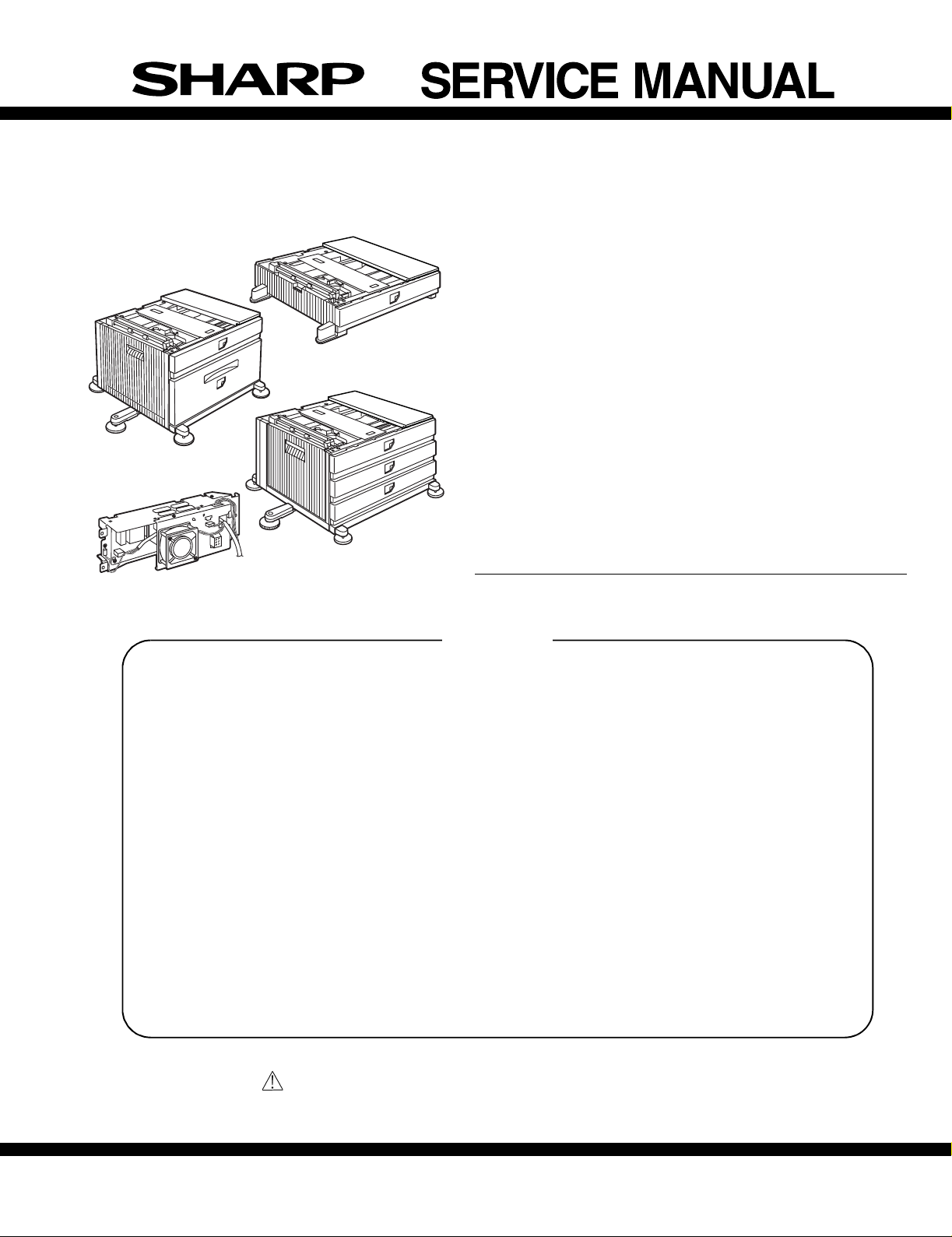
LASER PRINTER OPTIONS
P APER FEED UNIT
AR-D14
OPTIONAL POWER SUPPL Y UNIT
AR-D13
AR-D14
AR-MU1
MODEL AR-DC1
CONTENTS
[1] PRODUCT OUTLINE . . . . . . . . . . . . . . . . . . . . . . . . . . . . . . . . 1 - 1
[2] CONFIGURATION . . . . . . . . . . . . . . . . . . . . . . . . . . . . . . . . . . 2 - 1
[3] SPECIFICATIONS . . . . . . . . . . . . . . . . . . . . . . . . . . . . . . . . . . 3 - 1
[4] UNPACKING AND INSTALLATION. . . . . . . . . . . . . . . . . . . . . . 4 - 1
[5] EXTERNAL VIEWS AND INTERNAL STRUCTURES. . . . . . . 5 - 1
[6] ADJUSTMENTS. . . . . . . . . . . . . . . . . . . . . . . . . . . . . . . . . . . . 6 - 1
[7] DISASSEMBLY AND ASSEMBLY, MAINTENANCE. . . . . . . . . 7 - 1
[8] BLOCK DIAGRAM, WIRING DIAGRAM. . . . . . . . . . . . . . . . . . 8 - 1
[9] OTHERS. . . . . . . . . . . . . . . . . . . . . . . . . . . . . . . . . . . . . . . . . . 9 - 1
Parts marked with “ “ are important for maintaining the safety of the set.
Be sure to replace these parts with specified ones for maintaining the safety and performance of the set.
SHARP CORPORATION
This document has been published to be used for
after sales service only.
The contents are subject to change without notice.
Page 2

[1] PRODUCT OUTLINE
This unit is installed to one of the following machines to ser ve as a duplex module.
When installing the unit to one of the following machines, one of the multi-purpose tray (AR-MU1), the large capacity paper feed desk (AR-D13), and
the 3-stage paper feed desk (AR-D14) must be installed in advance. For the AR-D13 and the AR-D14, the option power unit (AR-DC1) must be
installed together.
Applicable models AR-P350 / P450, AR-M350 / M450
DM-3500 / 3501 / 4500 / 4501, DM-3551 / 4551
[2] CONFIGURATION
1. For the AR-D13 and the AR-D14, the option power unit (AR-DC1) must be installed together.
2. When the AR-MU1 and the male bin stacker (AR-MS1) or the finisher (AR-FN5) are installed, the optional power unit (AR-DC1) must be installed
together.
3. The AR-MU1 cannot be installed together with the saddle finisher (AR-FN)/Scanner unit (AR-EF1/EF2).
AR-EF1/AR-EF2
AR-FN7
AR-D14
AR-FN6
AR-MS1
AR-MU1
AR-D13
AR-DC1
Related to paper feed unit
Multi purpose drawer
Stand/3 x 500 sheet paper drawer
Stand/MPD & 2000 sheet paper drawer
AR-D13/D14/MU1/DC1 PRODUCT OUTLINE, CONFIGURATION-1
AR-MU1
AR-D14
AR-D13
B/W scanner module/DSPF
Scanner rack
Multi purpose drawer
Stand/3 x 500 sheet paper drawer
Stand/MPD & 2000 sheet
Duplex module/bypass tray
Duplex module
Saddle stitch finisher
Finisher
Mail-bin stacker
Exit tray
Punch unit
Upper exit tray extension
Multi-function controller board
PS3 expansion kit
Print server card
Fax memory (8 MB)
Network scanner expansion kit
Facsimile expansion kit
Hard disk drive
Power supply unit
Page 3
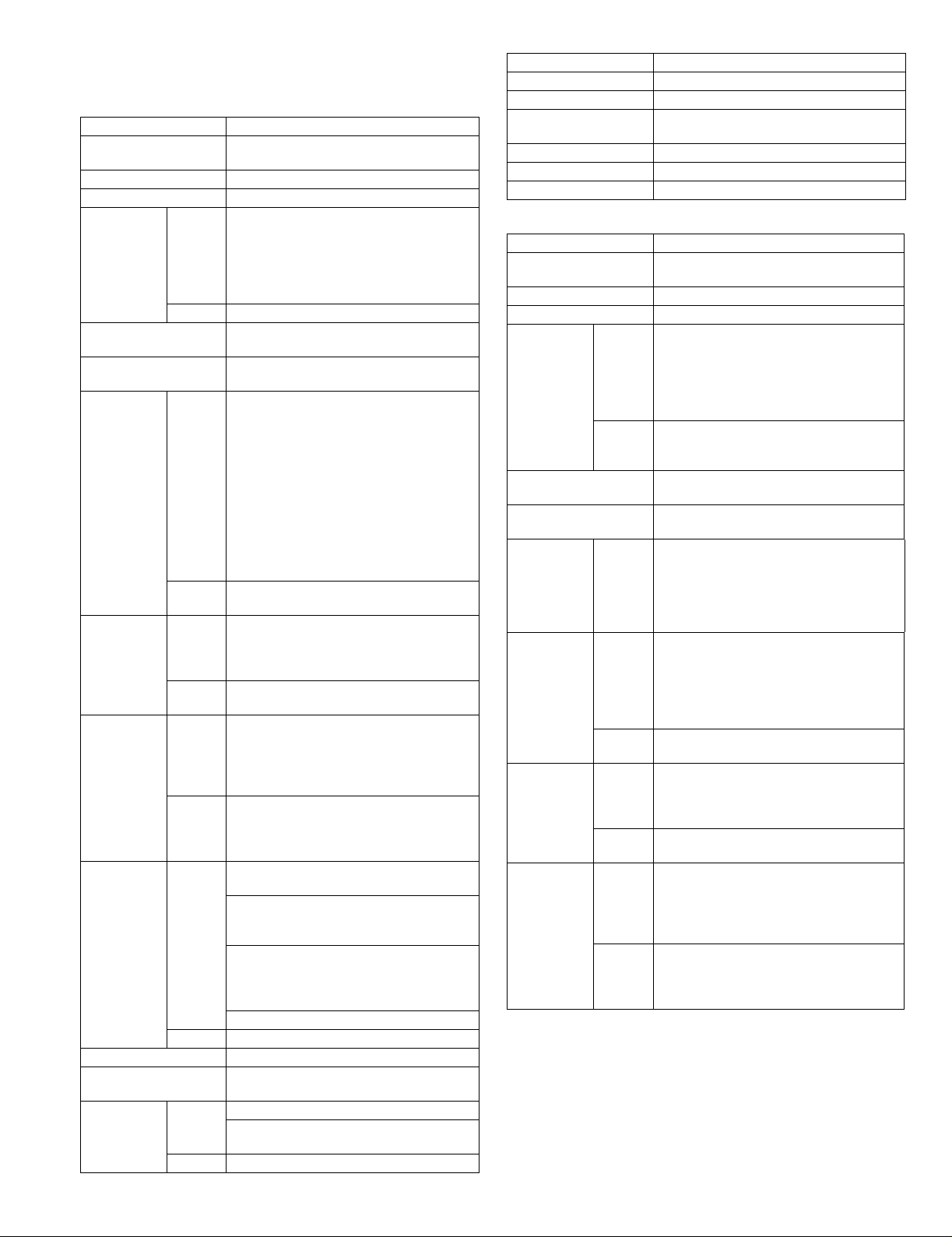
[3] SPECIFICATIONS
1. AR-D13
AR-D13
Type Stand MPD&2000 Sheet Paper Drawer
Transport speed To support 35-45 sheet/minute
Transport alignment Center alignment
Paper size 1 Tray A3, B4, A4, A4R, B5, B5R, A5R
2 Tray A4, 8.5"x11"
How to change the paper
size
Factory default paper
size setting
Media
available for
paper feeding
Paper
capacity
Paper type 1 Tray Plain, recycled, pre-printed, pre-punched,
Sizes to be
detected
Paper balance detection Provided (paper empty and 6 steps)
Paper loading system To be loaded from the upper side with front
Tray ascent/
descent time
1 Tray Plain paper:60-128g/m² / 16-34lbs
2 Tray Size guide plate comes with LCC unit.
1 Tray Standard:500sheets(80g/m²)
2 Tray 880+1,320sheets(64g/m²) /
2 Tray Plain, recycled, pre-printed, pre-punched,
1 Tray AutomaticAuto-AB:
2 Tray Size setting by the serviceman
Ascent Within 12 seconds
Descent Own weight descent
(large capacity tray + multi purpose drawer)
11"x17", 8.5"x14", 8.5"x13", 8.5"x11",
8.5"x11"R, 5.5"x8.5"R
Executive, Japanese p/c, Monarch(envelope)
Com-10(envelope), DL(envelope),
C5(envelope), ISO B5(envelope)
Guide adjustment by user / Software setting
by user
8.5"x11"
Index paper:176g/m² / 47lbs
Cover paper:200-205g/m² / 54-55lbs
Envelope:75-90g/m², 20-24lbs
Transparency film:(TBD)
* Media heavier than 105g/m² should be
A4/8.5x11" or smaller. Media heavier than
120g/m² should be fed from shorter edge.
* Only single paper feed is enabled for
overlay copy or copy on back-side of printed
paper.
Plain 60-105g/m² / 16-28lbs
Post card:40sheets
Envelope:40sheets
Transparency film:40sheets
800+1,200sheets(80g/m²)
color, letter head, labels, heavy,
transparency, Japanese p/c, envelope
(User can set bi-type for each of the above
paper type.)
color, letter head
(User can set bi-type for each of the above
paper type.)
A3, B4, A4, A4R, B5, B5R, 8.5"x13", A5R
AutomaticAuto-Inch:
11"x17", 8.5"x14", 8.5"x11", 8.5"x11"R,
7.25"x10.5"R, 5.5" x 8.5R
Manual (input detection):
postal card, Monarch(envelope),
Com-10(envelope), DL(envelope),
C5(envelope), ISO B5(envelope)
Ignore detection selectable:
loading system
At paper empty , required ti me from tra y insert
to the empty detection
AR-D13
Dehumidification heater Not provided
Power consumption 32.2W or lower
Power source Supplied from main unit
(DC24V 1.3A / DC5V 0.2A)
External dimensions 585x530x404 (mm)
Occupied dimensions
Weight Approx. 35kg
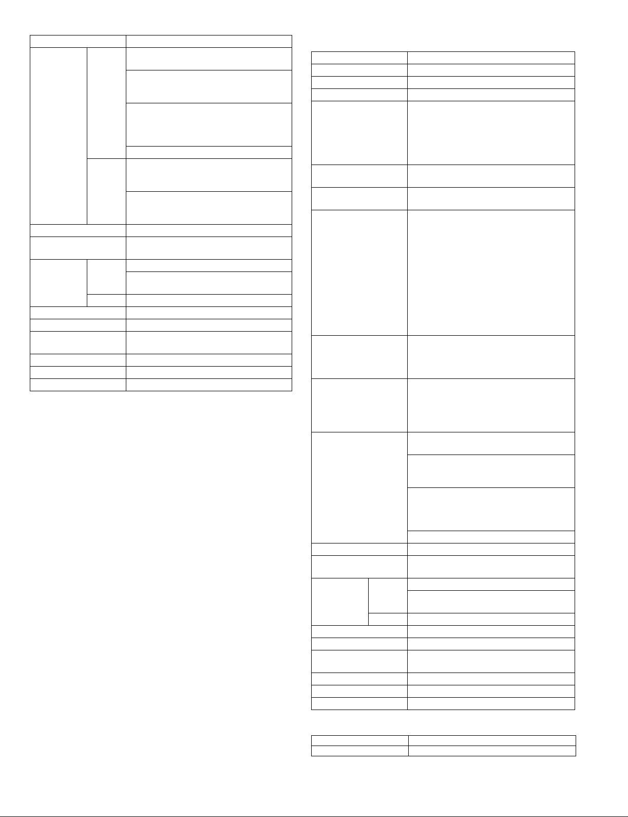
2. AR-D14
AR-D14
Type Stand /3x500 Sheet Paper Drawer
Transport speed To suppor t 35-45 sheet/minute
Transport alignment Center alignment
Paper size 1 Tray A3, B4, A4, A4R, B5, B5R, A5R
2 or 3
Tray
How to change the paper
size
Factory default paper
size sett ing
Media
available for
paper feeding
Media
available for
paper feeding
Paper
capacity
Paper type 1 Tray Plain, recycled, pre-printed, pre-punched,
1 Tray Plain paper:60-128g/m² / 16-34lbs
1 Tray * Media heavier than 105g/m² should be
2 or 3
Tray
1 Tray Standard:500sheets(80g/m²)
2 or 3
Tray
2 or 3
Tray
(2 paper trays + 1 multi purpose drawer)
11"x17", 8.5"x14", 8.5"x13", 8.5"x11",
8.5"x11"R, 5.5"x8.5"R
Executive, Japanese p/c,Monarch(envelope)
Com-10(envelope), DL(envel ope),
C5(envelope), ISO B5(env elope)
A3, B4, A4, A4R, B5, B5R
11"x17", 8.5"x14", 8.5"x13", 8.5"x11",
8.5"x11"R, 7.25"x10.5"R
Unit is delivered with paper guide set at max.
position in width. (Both of two cassettes.)
To be set to maximum paper guide width at
factory default status (for both trays)
Index paper:176g/m² / 47lbs
Cover paper:200-205g/m² / 54-55lbs
Envelope:75-90g/m², 20-24lbs
Transparency film:(TBD)
A4/8.5x11" or smaller. Media heavier than
120g/m² should be fed from shorter edge.
* Only single paper feed is enabled for
overlay copy or copy on back-side of printed
paper.
Plain 60-105g/m² / 16-28lbs
Post card:40sheets
Envelope:40sheets
Transparency film:40sheets
Standard
paper:500sheets X 2(64g/m²)
color, letter head, labels, heavy,
transparency, Japanese p/c, envelope
(User can set bi-type for each of the above
paper type.)
Plain, recycled, pre-printed, pre-punched,
color, letter head
(User can set bi-type for each of the above
paper type.)
AR-D13/D14/MU1/DC1 SPECIFICATIONS-1
Page 4
AR-D14
Sizes to be
detected
Paper balance detection Provided (paper empty and 3 steps)
Paper loading system To be loaded from the upper side with front
Tray ascent/
descent time
Dehumidification heater Included in the service kit.
Power consumption 32.2W or lower
Power source Supplied from main unit
External dimensions 585x530x404 (mm)
Occupied dimensions
Weight Approx. 32kg
1 Tray AutomaticAuto-AB:
A3, B4, A4, A4R, B5, B5R, 8.5"x13", A5R
AutomaticAuto-Inch:
11"x17", 8.5"x14", 8.5"x11", 8.5"x11"R,
7.25"x10.5"R, 5.5" x 8.5R
Manual (input detection):
postal card, Monarch(envelope),
Com-10(envelope), DL(envelope),
C5(envelope), ISO B5(envelope)
Ignore detection selectable:
2 or 3
Tray
Ascent Within 7 seconds
Descent Own weight descent
Automatic detection-AB
(200V system):A3, B4, A4, A4R, B5, B5R,
8.5"x13"
Automatic detection-inch
(100V system): 11"x17", 8.5"x14", 8.5"x13",
8.5"x11", 8.5"x11"R, 7.25"x10.5"R
loading system
At paper empty, required time from tray
insert to the empty detection
(DC24V 1.3A / DC5V 0.2A)
3. AR-MU1
AR-MU1
Type Multi purpose drawer for add-on use
Transport speed To suppor t 35-55 sheets/minute
Transport alignment Center alignment
Paper size A3, B4, A4, A4R, B5, B5R, A5R
How to change the paper
size
Factory default paper
size sett ing
Media available f or paper
feeding
Paper capacity Standard:500sheets(80g/m²)
Paper type Plain, recycled, pre-printed, pre-punched,
Sizes to be detected AutomaticAuto-AB:
Paper balance detection Provided (paper empty and 3 steps)
Paper loading system To be loaded from the upper side with front
Tray ascent/
descent time
Dehumidification heater Included in the ser vice kit.
Power consumption 24.5W or lower
Power source Supplied from main unit
External dimensions 585x530x114 (mm)
Occupied dimensions
Weight Approx. 11kg
Ascent Within 7 seconds
Descent Own weight descent
11"x17", 8.5"x14", 8.5"x13", 8.5"x11",
8.5"x11"R, 5.5"x8.5"R
Executive , Japanese p/c, Monarch(envelope)
Com-10(envelope), DL(envel ope),
C5(envelope), ISO B5(env elope)
Guide adjustment by user / Software setting
by user
To be set to maximum paper guide width at
factory default status.
Plain paper:60-128g/m² / 16-34lbs
Index paper:176g/m² / 47lbs
Cover paper:200-205g/m² / 54-55lbs
Envelope:75-90g/m², 20-24lbs
Transparency film:(TBD)
* Media heavier than 105g/m² should be
A4/8.5x11" or smaller. Media heavier than
120g/m² should be fed from shorter edge.
* Only single paper feed is enabled for
overlay copy or copy on back-side of printed
paper.
Post card:40sheets
Envelope:40sheets
Transparency film:40sheets
color, letter head, labels, heavy,
transparency, Japanese p/c, envelope
(User can set bi-type for each of the above
paper type.)
A3, B4, A4, A4R, B5, B5R, 8.5"x13", A5R
AutomaticAuto-Inch:
11"x17", 8.5"x14", 8.5"x11", 8.5"x11"R,
7.25"x10.5"R, 5.5" x 8.5R
Manual (input detection):
postal card, Monarch(envelope),
Com-10(envelope), DL(envel ope),
C5(envelope), ISO B5(env elope)
Ignore detection selectable:
loading system
At paper empty , required time from tra y insert
to the empty detection
(DC24V 1A / DC5V 0.1A)
4. AR-DC1
Input AC 100-127V / 220-240V (Two kinds)
Output DC 24V
AR-D13/D14/MU1/DC1 SPECIFICATIONS-2
Page 5
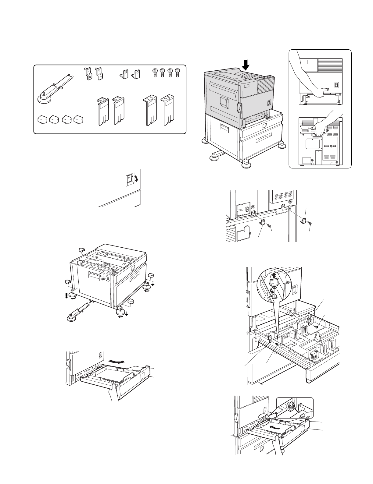
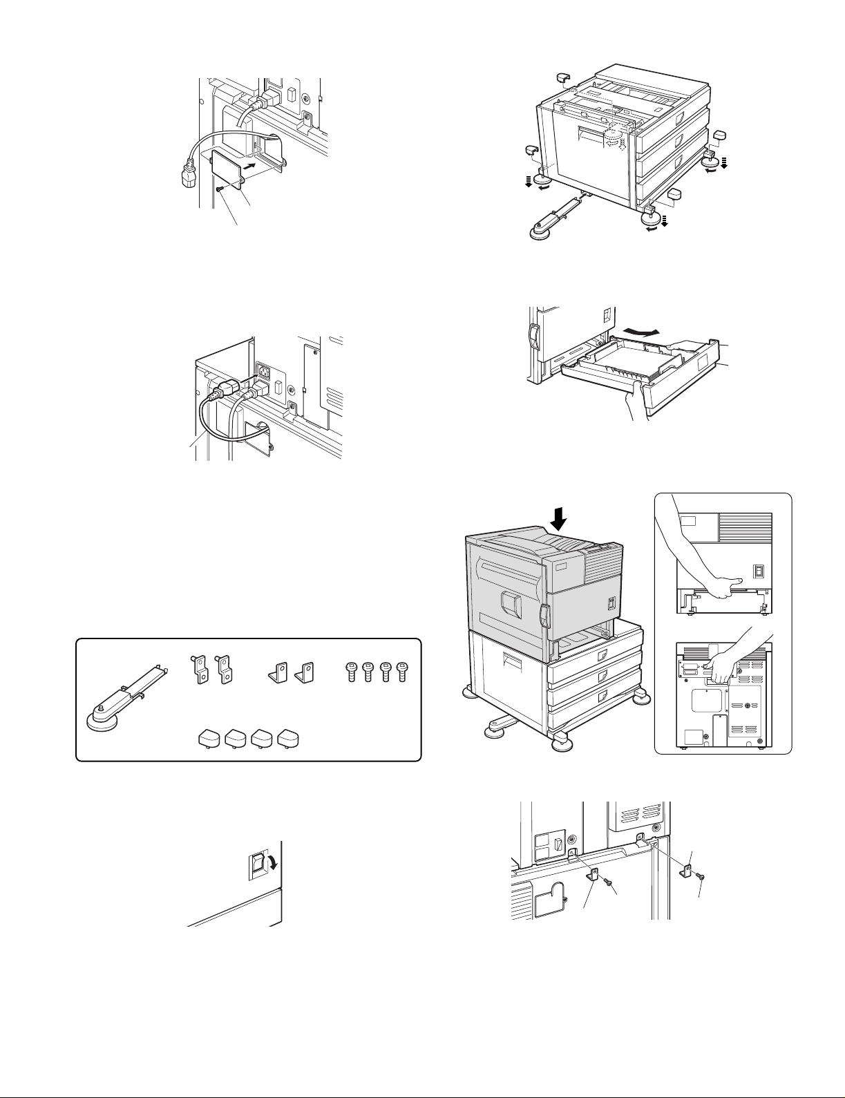
[4] UNPACKING AND INSTALLATION
Screw
Screw
Front
mounting plate
Front mounting
plate
1.AR-D13
<Before installation>
•For installation, a power supply unit (AR-DC1) is needed.
<Parts included>
<2>Hold the main unit of the printer at the positions shown in the
illustration and put the main unit on the stand/paper drawer so that
the front side and the left side of the main unit are al igned to those of
the stand/paper drawer.
Front side
Left adjuster: 1 pc.
Adjuster covers: 4 pcs.
Front mounting
plates: 2 pcs.
Left paper guides: 2 pcs. Right paper guides: 2 pcs.
Rear mounting
plates: 2 pcs.
Screws: 4 pcs.
1) Turn off the main switch of the main unit of the printer.
Tur n the main switch located on the front side of the printer to the
"OFF" position.
Then remove the power plug from the outlet.
"OFF"
2) Attach the adjusters and adjust them.
<1>Inser t the left adjusters to the stand/paper drawer.
<2>T urn the five adjusters to lower them until they touch the floor.
<3>Attach the four adjuster covers.
3
3
3
2
Rear side
4) Connect the main unit to the stand/paper drawer.
<1>Attach the rear mounting plates with two supplied screws.
Rear
mounting plate
Screw
Rear mounting plate
Screw
<2>Pull out the upper paper tray of the stand/paper drawer until it stops
and attach the front mounting plates with two supplied screws.
Then, remove the lock of the paper tra y and close the tray.
2
2
1
3) Put the main unit of the printer on the stand/paper drawer.
<1>Pull out the paper tray of the main unit until it stops and then remove
it by lifting both ends of the tray.
3
2
AR-D13/D14/MU1/DC1 UNPACKING AND INSTALLATION-1
<3>Reattach the paper tray of the main unit.
Page 6

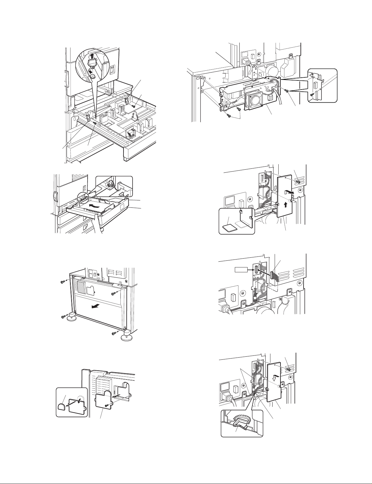
5) Remove the rear cabinet of the stand/paper drawer and remove the
AC inlet cover.
<1>Remove the four screws that fix the rear cabinet and then remov e the
rear cabinet.
Rear cabinet
<2>Remove the screw that fixes the AC inlet cover and then remove the
AC inlet cover.
<3>Process the AC inlet cover as shown in the illustration.
Cut out.
AC inlet cover
<2>Connect the optional power supply harness connector to CN11 (red
connector) of the PCU PWB of the main unit of the printer.
Connector
CN11
<3>Reattach the harness cover to its original position and fix it with the
removed screw.
At this time, ensure that the optional power supply harness are
arranged as shown in the illustration.
•Fix the harness securely to the wire saddle.
Screw
Optional power
supply harness
2/ Screw
Harness cover
Wire saddle
6) Attach the power supply unit.
Attach the power supply unit to the positioning portion of the multi
purpose drawer and then fix it with three supplied screws.
Screws
Screws
Power supply unit
7) Connect the power supply unit harness to the PCU PWB of the main
unit of the printer.
<1>Remove the screw that fixes the harness cover of the main unit of the
printer and slide the harness cover up to remove it.
Process the harness cover as shown in the illustration.
Screw
Wire saddle
8) Connect the relay harness of the stand/paper drawer to the power
supply unit.
Connect the relay harness of the stand/paper drawer to the
connector of the power supply unit.
Connector of the power supply connector
Relay harness of the
stand/paper drawer
9) Attach the rear cabinet of the stand/paper drawer.
<1>Pass the cord of the power supply unit through the hole of the rear
cabinet and attach the rear cabinet to the stand/paper drawer.
Cut out.
Harness cover
Rear cabinet
AR-D13/D14/MU1/DC1 UNPACKING AND INSTALLATION-2
Page 7
<2>Attach the AC inlet cover to the rear cabinet of the stand/paper
Front side
Rear side
drawer and fix it with the removed screw.
<3>Attach the four adjuster covers.
3
AC inlet cover
Screw
10) Connect the AC cord of the power supply unit to the main unit of the
printer.
Connect the AC cord of the power supply unit to the inlet connector
of the main unit of the printer at the location shown in the illustration.
AC cord
11) Attach the paper guides to the lower tra y (large capacity tra y) and set
the size.
Refer to "Setting and adjustment" described later.
12) Adjust the position of the paper guides of the upper paper tray of the
stand/paper drawer.
Refer to "Setting and adjustment" described later.
2.AR-D14
<Before installation>
•For installation, a power supply unit (AR-DC1) is needed.
3
3
2
2
2
1
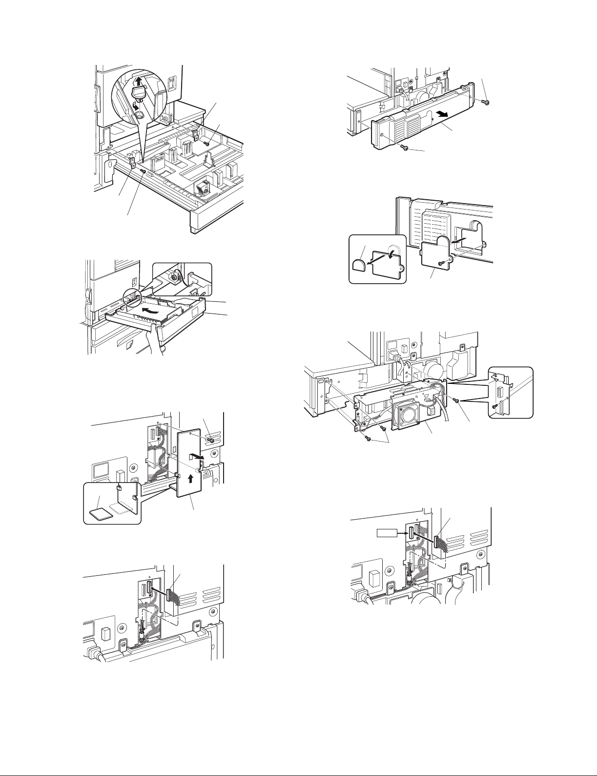
3) Put the main unit of the printer on the stand/paper drawer.
<1>Pull out the paper tray of the main unit until it stops and then remove
it by lifting both ends of the tray.
<2>Hold the main unit of the printer at the positions shown in the
illustration and put the main unit on the stand/paper drawer so that
the front side and the left side of the main unit are al igned to those of
the stand/paper drawer.
3
2
<Parts included>
Screws: 4 pcs.
Left adjuster: 1 pc.
Front mounting
plates: 2 pcs.
Rear mounting
plates: 2 pcs.
Adjuster covers: 4 pcs.
1) Turn off the main switch of the main unit of the printer.
Tur n the main switch located on the front side of the printer to the
"OFF" position.
Then remove the power plug from the outlet.
"OFF"
2) Attach the adjusters and adjust them.
<1>Inser t the left adjusters to the stand/paper drawer.
<2>T urn the five adjusters to lower them until they touch the floor.
4) Connect the main unit to the stand/paper drawer.
<1>Attach the rear mounting plates with two supplied screws.
Rear
mounting plate
Screw
Rear mounting plate
Screw
AR-D13/D14/MU1/DC1 UNPACKING AND INSTALLATION-3
Page 8
<2>Pull out the upper paper tray of the stand/paper drawer until it stops
and attach the front mounting plates with two supplied screws.
Then, remove the lock of the paper tray and close the tray.
Remove the locks of the middle tray and the lower tray similarly.
Front
mounting plate
Screw
Front mounting
plate
Screw
<3>Reattach the paper tray of the main unit.
6) Attach the power supply unit.
Attach the power supply unit to the positioning portion of the multi
purpose drawer and then fix it with three supplied screws.
Screws
Screws
Power supply unit
7) Connect the power supply unit harness to the PCU PWB of the main
unit of the printer.
<1>Remove the screw that fixes the harness cover of the main unit of the
printer and slide the harness cover up to remove it.
Process the harness cover as shown in the illustration.
Screw
5) Remove the rear cabinet of the stand/paper drawer and remove the
AC inlet cover.
<1>Remove the four screws that fix the rear cabinet and then remov e the
rear cabinet.
Rear cabinet
<2>Remove the screw that fixes the AC inlet cover and then remove the
AC inlet cover.
<3>Process the AC inlet cover as shown in the illustration.
Cut out.
Harness cover
<2>Connect the optional power supply harness connector to CN11 (red
connector) of the PCU PWB of the main unit of the printer.
Connector
CN11
<3>Reattach the harness cover to its original position and fix it with the
removed screw.
At this time, ensure that the optional power supply unit harness is
arranged as shown in the illustration.
•Fix the harness securely to the wire saddle.
Screw
Optional power
supply harness
Cut out.
AC inlet cover
Harness cover
Wire saddle
Wire saddle
AR-D13/D14/MU1/DC1 UNPACKING AND INSTALLATION-4
Page 9

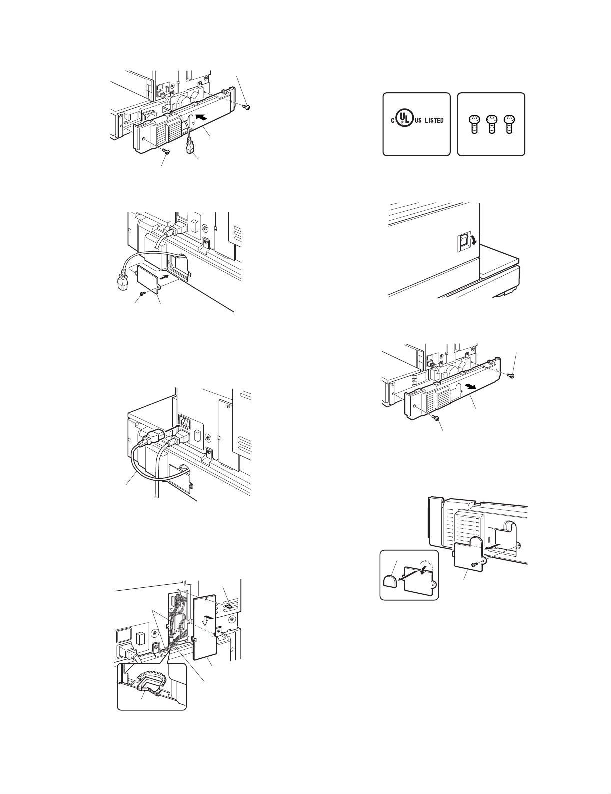
8) Connect the relay harness of the stand/paper drawer to the power
supply unit.
Connect the relay harness of the stand/paper drawer to the
connector of the power supply unit.
Connector of the power supply connector
3.AR-MU1
<Before installation>
•When installing AR-MS1, if you install a finisher or mail-bin stacker
together, a power supply unit (AR-DC1) is needed.
<Parts included>
Relay harness of the
stand/paper drawer
9) Attach the rear cabinet of the stand/paper drawer.
<1>Pass the cord of the power supply unit through the hole of the rear
cabinet and attach the rear cabinet to the stand/paper drawer.
Rear cabinet
<2>Attach the AC inlet cover to the rear cabinet of the stand/paper
drawer and fix it with the removed screw.
Front mounting plates: 2 pcs.
Rear mounting plates: 2 pcs.
Screws: 4 pcs.
1) Turn off the main switch of the main unit of the printer.
Turn the main switch located on the front side of the main unit to the
"OFF" position.
Then, remove the power plug of the main unit from the outlet.
2) Put the main unit of the printer on the multi purpose drawer.
<1>Pull out the paper tray of the main unit until it stops and then remove
it by lifting both ends of the tray.
<2>Hold the main unit of the printer at the positions shown in the
illustration and put the main unit on the multi purpose drawer so that
the front side and the left side of the main unit are al igned to those of
the multi purpose drawer.
Front side
AC inlet cover
Screw
10) Connect the AC cord of the power supply unit to the main unit of the
printer.
Connect the AC cord of the power supply unit to the inlet connector
of the main unit of the printer at the location shown in the illustration.
AC cord
11) Adjust the position of the paper guides of the upper paper tray of the
stand/paper drawer.
Refer to "Setting and adjustment" described later.
AR-D13/D14/MU1/DC1 UNPACKING AND INSTALLATION-5
Rear side
3) Connect the main unit of the printer to the multi purpose drawer.
<1>Attach the rear mounting plates with two supplied screws.
Rear mounting
plate
Screw
Rear mounting plate
Screw
Page 10
<2>Pull out the paper tray of the multi purpose drawer until it stops and
attach the front mounting plates with two supplied screws.
Then, remove the lock of the paper tray and close the tray.
Front
mounting plate
Screw
Front mounting plate
Screw
5) Remove the rear cabinet of the multi purpose drawer.
<1>Remove the two screws that fix the rear cabinet of the multi purpose
drawer and then remove the rear cabinet.
Screw
Rear cabinet
Screw
<2>Remove the screw that fixes the AC inlet cover and then remove the
AC inlet cover.
Process the AC inlet cover as shown in the illustration.
<3>Reattach the paper tray of the main unit of the printer.
4) Connect the harness to the main unit of the printer.
<1>Remove the screw that fixes the harness cover of the main unit of the
printer and then slide the harness cover up to remove it.
Process the harness cover as shown in the illustration.
Screw
Cut out.
Harness cover
Cut out.
AC inlet cover
6) Attach the power supply unit.
Attach the power supply unit to the positioning portion of the multi
purpose drawer and then fix it with three supplied screws.
Screws
Screws
Optional power supply unit
7) Connect the power supply unit harness to the PCU PWB of the main
unit of the printer.
Connect the power supply harness connector to CN11 (red
connector) of the PCU PWB of the main unit of the printer.
Connector
<2>Connect the connector of the relay harness of the multi purpose
drawer to the connector of the PCU PWB of the main unit of the
printer.
Connector
If you do not install a finisher, saddle stitch finisher or mail-bin stacker,
the steps below are not needed. Proceed to step 10).
AR-D13/D14/MU1/DC1 UNPACKING AND INSTALLATION-6
CN11
Page 11
8) Attach the rear cabinet of the paper tray.
<1>Pass the AC cord of the power supply unit as shown in the illustration
and attach the rear cabinet with two screws.
Screw
Rear cabinet
4.AR-DC1
<Before installation>
•Start installation after checking that the DATA indicator on the operation
panel is not lit or blinking.
Parts included
I.T.E.
ACCESSORY
9K11
Screws (3)
Screw
AC cord
<2>Attach the AC inlet cover to the paper tray and fix it with the remov ed
screw.
Screw
AC inlet cover
9) Connect the AC cord of the power supply unit to the main unit of the
printer.
Connect the AC cord of the power supply unit to the inlet connector
of the main unit of the printer at the location shown in the illustration.
Then, proceed to step 11).
1) Turn the main switch of the printer to "OFF".
Turn the main switch located on the front of the printer to "OFF".
Then, remove the power plug of the printer from the outlet.
"OFF"
2) Remove the multi rear cabinet.
Remove the two screws that secure the multi rear cabinet and
remove the multi rear cabinet.
Screw
Multi rear cabinet
Screw
AC cord
10) Attach the harness cover.
Reattach the harness cover to its original position and fix it with the
removed screw.
At this time, ensure that the power supply unit harness is arranged
as shown in the illustration.
•Fix the harness securely to the wire saddle.
Screw
Optional power
supply harnesses
Harness cover
Wire saddle
Wire saddle
11) Adjust the position of the paper guides of the paper tray.
Refer to "Setting and adjustment" described later.
3) Remov e the AC inlet cover from the multi rear cabinet.
Remove the screw that secures the AC inlet cover and remove the
AC inlet cover.
Work the AC inlet cover as shown in the illustration.
Cut-out
AC inlet cover
AR-D13/D14/MU1/DC1 UNPACKING AND INSTALLATION-7
Page 12

4) Attach an optional power supply unit to the multi-purpose section.
Attach an optional power supply unit to the positioning portion of the
multi-purpose section and secure it with the three screws included in
this product.
6) Attach the multi rear cabinet.
<1>Pass the AC cord of the optional power supply unit as shown in the
illustration and secure the multi rear cabinet with the two screws.
Screw
Multi rear cabinet
Screws
Screw
Optional power supply unit
5) Connect the optional power supply harness to the PCU PWB of the
printer.
<1>Remove the screw that secures the harness cover of the printer and
slide the harness cover upward to remove it.
Work the harness cover as shown in the illustration.
Screw
Cut-out
Harness cover
<2>Connect the connector of the optional power supply harness to
CN11 of the PCU PWB of the printer.
Connector
CN11
Screw
AC cord
<2>Attach the AC inlet cover to the multi rear cabinet and secure it with
the removed screw.
Screw
AC inlet cover
7) Connect the AC cord of the optional power supply unit to the printer.
Connect the AC cord of the optional power supply unit to the positi on
of the inlet connector of the printer shown in the illustration.
AC cord
<3>Reattach the harness cover to its original position and secure it with
the removed screw.
At this time, check that wiring of the optional power supply harness
has been handled as shown in the illustration.
Screw
Optional power
supply harness
Harness cover
Harness cover
8) Turn the power switch of the printer to "ON".
Insert the power plug of the printer to the outlet.
Then, turn the main switch located on the front of the printer to "ON".
"ON"
AR-D13/D14/MU1/DC1 UNPACKING AND INSTALLATION-8
Page 13
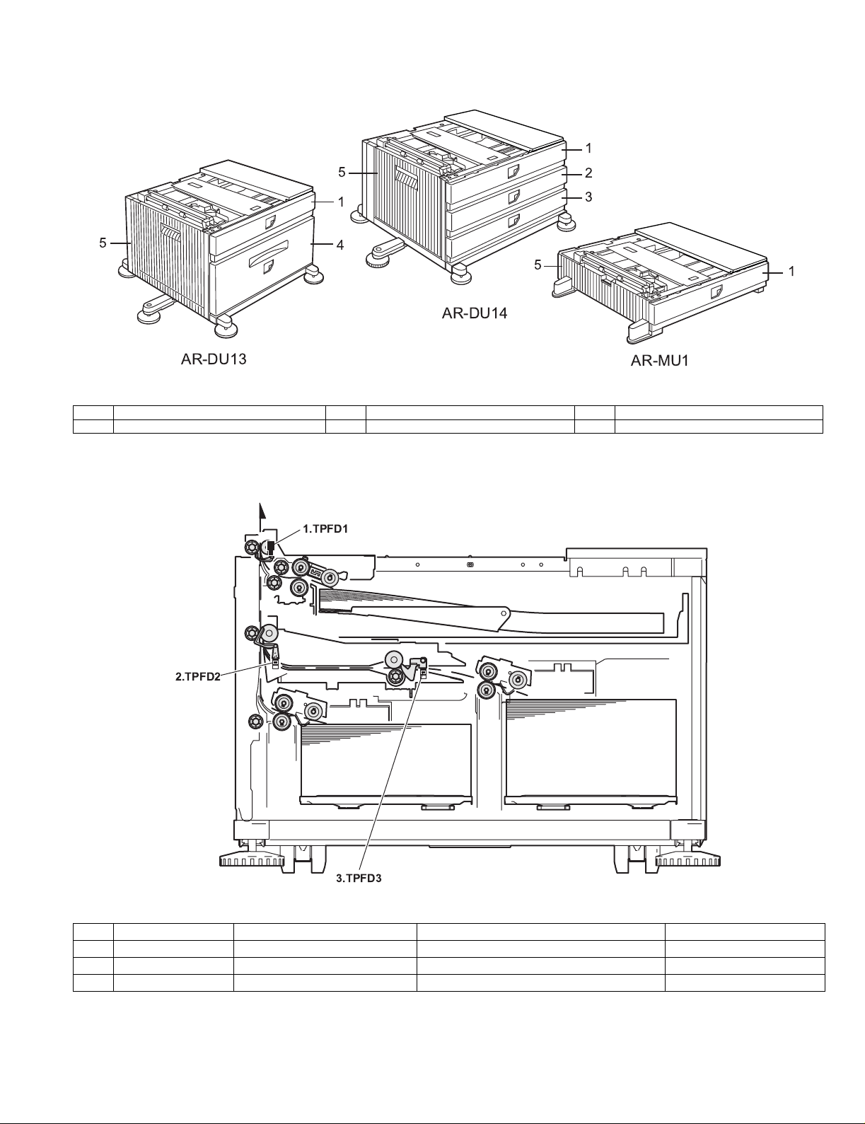
[5] EXTERNAL VIEWS AND INTERNAL STRUCTURES
A. External view
5
1
1
2
3
5
4
5
AR-DU14
AR-DU13
1 Multi-purpose tray (No. 2 tray) 2 No. 3 tray 3 No. 4 tray
4 Large capacity tray 5 Desk left door
B. Internal structure
(1) AR-D13
1.TPFD1
1
AR-MU1
1TPFD1
2TPFD2
3TPFD3
2.TPFD2
3.TPFD3
Code Name Function Remark
AR-D13/D14/MU1/DC1 EXTERNAL VIEWS AND INTERNAL STRUCTURES-1
Page 14
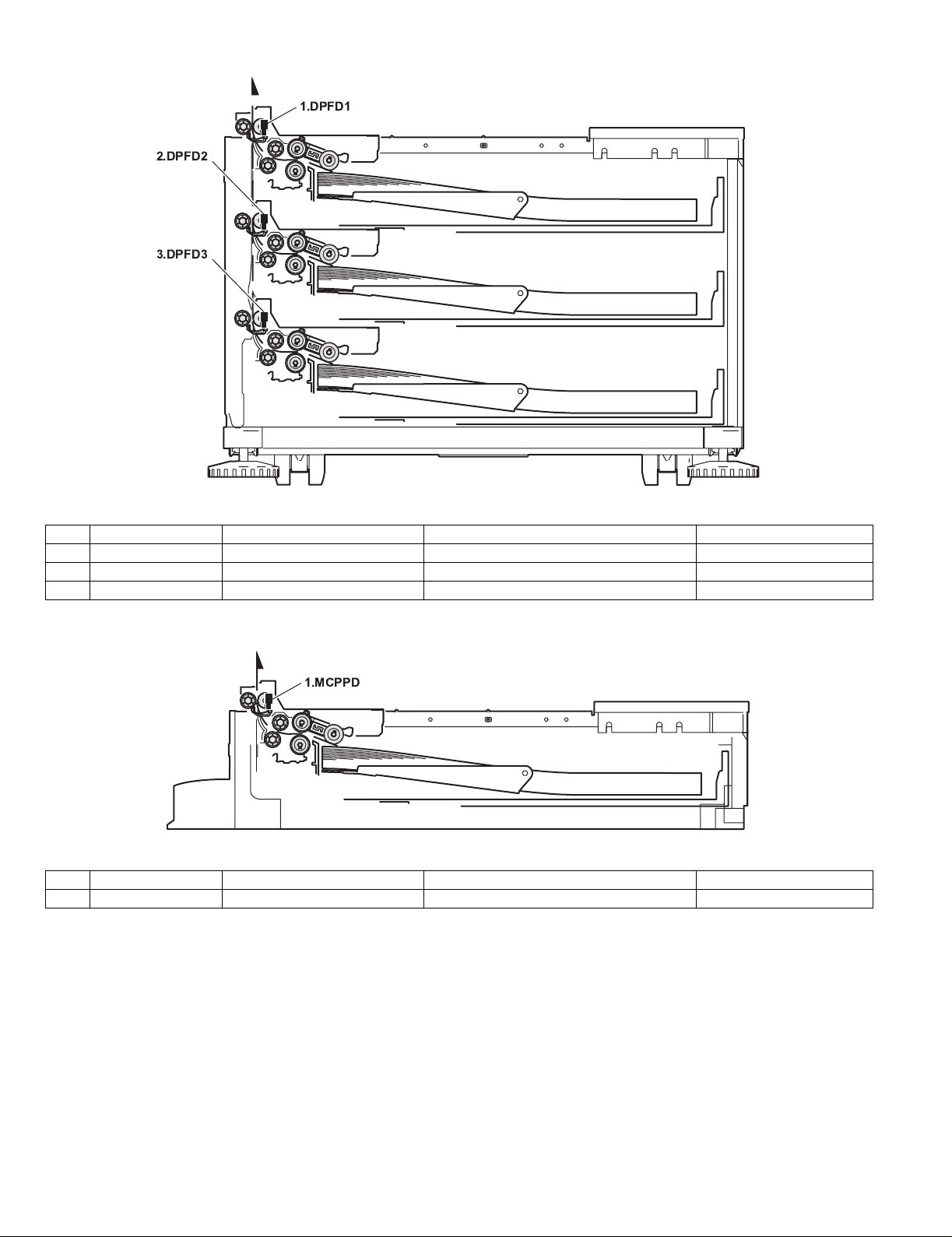
(2) AR-D14
1.DPFD1
2.DPFD2
3.DPFD3
1DPFD1
2DPFD2
3DPFD3
(3) AR-MU1
1MCPPD
Code Name Function Remark
1.MCPPD
Code Name Function Remark
AR-D13/D14/MU1/DC1 EXTERNAL VIEWS AND INTERNAL STRUCTURES-2
Page 15

C. Motor, clutch
(1) AR-D13
3.TPFCL
2.TPCL1
1.TLUM1
4.MCLUM
5.MCPCL
6.TMM
7.TPCL2
8.TLUM2
Code Name Function Remark
1 TLUM1 Tandem tray 1 lift-up motor Tandem tray 1 lift-up
2 TPCL1 Tandem tray 1 paper feed clutch Clutch for paper feed from tandem tray 1
3 TPFCL LCC transport clutch Clutch for transport from LCC desk
4 MCLUM Multi-purpose tray lift-up motor Multi-purpose tray lift-up
5 MCPCL Multi-purpose paper feed clutch Clutch for paper feed from Multi-purpose tray
6 TMM LCC transport motor LCC desk paper transport
7 TPCL2 T andem tray 2 paper feed clutch Clutch for paper feed from tandem tray 2
8 TLUM2 Tandem tray 2 lift-up motor Tandem tray 2 lift-up
AR-D13/D14/MU1/DC1 EXTERNAL VIEWS AND INTERNAL STRUCTURES-3
Page 16

(2) AR-D14
5.MCPCL
4.MCLUM
3.DPFCL
2.DLUM1
1.DLUM2
Code Name Function Remark
1 DLUM2 No. 4 tray lift-up motor Gate switch between duplex and paper exit
2 DLUM1 No. 3 tray lift-up motor Cooling the machine and inside of ADU
3 DPFCL Desk transport clutch Clutch for transport from LCC desk
4 MCLUM Multi-purpose tray lift-up motor Multi-purpose tray lift-up
5 MCPCL Multi-purpose paper feed clutch Clutch for paper feed from Multi-purpose tray
6 DMM No. 3 tray desk transport motor No. 3 tray desk paper transport
7 DPCL2 No. 4 tray paper feed clutch Clutch for paper feed from tandem tray 2
8 DPCL1 No. 3 tray paper feed clutch Clutch for paper feed from tandem tray 1
6.DMM
8.DPCL1
7.DPCL2
(3) AR-MU1
4.MCM
3.MCPCL
2.MCLUM
1.MCFCL
Code Name Function Remark
1 MCFCL Multi-purpose tray transport clutch Multi-purpose tray transport clutch
2 MCLUM Multi-purpose tray lift-up motor Multi-purpose tray lift-up
3 MCPCL Multi-purpose paper feed clutch Clutch for paper feed from Multi-purpose tray
4 MCM Multi-purpose tray transport motor Multi-purpose tray paper transport
AR-D13/D14/MU1/DC1 EXTERNAL VIEWS AND INTERNAL STRUCTURES-4
Page 17

D. PWB, sensor
(1) AR-D13
2.TSPD1
3.TDRS
5.TPFD3
4.MCSPD
6.MCLUD
21.MP tray rear edge size PWB
7.MCSS1
9.MCSS3
8.MCSS2
10.MCSS4
1.TPFD2
19.TLUD1
20.TPED1
18.
17.MCPWS
14.TSPD2
15.MCPED
16.TPFD1
11.TTSD
12.TLUD2
13.TPED2
Code Name Function Active condition Remark
1 TPFD2 Tandem tray paper transport sensor 2 Tandem tray paper transport detection L : Paper detected
2 TSPD1 Tandem 1 tray
remaining paper quantity sensor
Tandem 1 tray
remaining paper quantity detection
3 TDRS Side door open/close sensor Side door open/close detection H : Door closed
4 MCSPD MP tray remaining paper quantity sensor MP tray remaining paper quantity detection
5 TPFD3 Tandem tray paper transport sensor 3 Tandem tray paper transport detection L : Paper detected
6 MCLUD MP tray upper limit sensor MP tray upper limit detection H : Upper limit
detected
7 MCSS1 MP tray rear edge sensor 1 MP tray rear edge size detection L : When pressed In MP tray rear
edge size PWB
8 MCSS2 MP tray rear edge sensor 2 MP tray rear edge size detection L : When pressed In MP tray rear
edge size PWB
9 MCSS3 MP tray rear edge sensor 3 MP tray rear edge size detection L : When pressed In MP tray rear
edge size PWB
10 MCSS4 MP tray rear edge sensor 4 MP tray rear edge size detection L : When pressed In MP tray rear
edge size PWB
11 TTSD Tandem tray open/close sensor Tandem tray open/close detection H : Tray closed
12 TLLD2 Tandem 2 tray upper limit sensor Tandem tray 2 upper limit detection L : Upper limit
detected
13 TPED2 Tandem 2 tray paper empty sensor Tandem tray 2 paper empty detection H : Paper loaded
14 TSPD2 Tandem 2 tray
remaining paper quantity sensor
Tandem 2 tray
remaining paper quantity detection
15 MCPED MP tray paper empty sensor MP tray paper empty detection L : Paper loaded
16 TPFD1 Tandem tray paper transport sensor 1 Tandem tray paper transport detection L : Paper detected
17 MCPWS MP tray width sensor MP tray paper width detection Slide volume
18 Control PWB Control PWB Communication with the machine,
machine operation control
19 TLLD1 Tandem 1 tray upper limit sensor Tandem tray 1 upper limit detection L : Upper limit
detected
20 TPED1 Tandem 1 tray paper empty sensor Tandem tray 1 paper empty detection H : Paper loaded
21 MP tray rear
MP tray rear edge size PWB Multi-purpose tray rear edge size detection
edge size PWB
AR-D13/D14/MU1/DC1 EXTERNAL VIEWS AND INTERNAL STRUCTURES-5
Page 18

(2) AR-D14
1.DDRS
2.MCSPD
3.
4.MCLUD
5.MCPED
28.MP tray rear edge size PWB
6.MCSS1
8.MCSS3
29.No. 3 tray rear edge size PWB
7.MCSS2
9.MCSS4
27.DSPD1
26.DLUD1
25.DSPD2
24.MCPWS
23.DLUD2
22.DPED2
21.DPFD3
19.DPED1
20.DPFD2
10.DCSS11
12.DCSS13
30.No. 4 tray rear edge size PWB
14.DCSS21
18.DPFD1
16.DCSS23
11.DCSS12
13.DCSS14
15.DCSS22
17.DCSS24
Code Name Function Active condition Remark
1 DDRS Side door open/close sensor Side door open/close detection H : Door closed
2 MCSPD MP tray
remaining paper quantity sensor
MP tray
remaining paper quantity detection
3 Control PWB Control PWB Communication with the machine,
machine operation control
4 MCLUD MP tray upper limit sensor MP tray upper limit detection H : Upper limit
detected
5 MCPED MP tray paper empty sensor MP tray paper empty detection L : Paper loaded
6 MDSS1 MP tray rear edge sensor 1 MP tray rear edge size detection L : When pressed In MP tray rear edge size PWB
7 MCSS2 MP tray rear edge sensor 2 MP tray rear edge size detection L : When pressed In MP tray rear edge size PWB
8 MCSS3 MP tray rear edge sensor 3 MP tray rear edge size detection L : When pressed In MP tray rear edge size PWB
9 MCSS4 MP tray rear edge sensor 4 MP tray rear edge size detection L : When pressed In MP tray rear edge size PWB
10 DCSS11 No. 3 tray rear edge sensor 1 No. 3 tray rear edge size detection L : When pressed In No. 3 tray rear edge size PWB
11 DCSS12 No. 3 tray rear edge sensor 2 No. 3 tray rear edge size detection L : When pressed In No. 3 tray rear edge size PWB
12 DCSS13 No. 3 tray rear edge sensor 3 No. 3 tray rear edge size detection L : When pressed In No. 3 tray rear edge size PWB
13 DCSS14 No. 3 tray rear edge sensor 4 No. 3 tray rear edge size detection L : When pressed In No. 3 tray rear edge size PWB
14 DCSS21 No. 4 tray rear edge sensor 1 No. 4 tray rear edge size detection L : When pressed In No. 4 tray rear edge size PWB
15 DCSS22 No. 4 tray rear edge sensor 2 No. 4 tray rear edge size detection L : When pressed In No. 4 tray rear edge size PWB
16 DCSS23 No. 4 tray rear edge sensor 3 No. 4 tray rear edge size detection L : When pressed In No. 4 tray rear edge size PWB
17 DCSS24 No. 4 tray rear edge sensor 4 No. 4 tray rear edge size detection L : When pressed In No. 4 tray rear edge size PWB
18 DPFD1 Desk paper transport sensor 1 Desk paper transport detection L : Paper detected
19 DPED1 N. 3 tray paper empty sensor N. 3 tray paper empty detection L : Paper loaded
20 DPFD2 Desk paper transport sensor 2 Desk paper transport detection L : Paper detected
21 DPFD3 Desk paper transport sensor 3 Desk paper transport detection L : Paper detected
22 DPED2 No. 4 tray paper empty sensor No. 4 tray paper empty detection L : Paper loaded
23 DLUD2 No. 4 tray upper limit sensor No. 4 tray upper limit detection H : Upper limit
detected
24 MCPWS MP tray width sensor MP tray paper width detection Analog voltage Slide volume
25 DSPD2 No. 4 tray
remaining paper quantity sensor
No. 4 tray
remaining paper quantity detection
26 DLUD1 No. 3 tray upper limit sensor No. 3 tray upper limit detection H : Upper limit
detected
27 DSPD1 No. 3 tray
remaining paper quantity sensor
28 MP tray rear
MP tray rear edge size PWB MP tray rear edge size detection
No. 3 tray
remaining paper quantity detection
edge size PWB
29 No. 3 tra y rear
No. 3 tray rear edge size PWB No. 3 tray rear edge size detection
edge size PWB
30 No. 4 tra y rear
No. 4 tray rear edge size PWB No. 4 tray rear edge size detection
edge size PWB
AR-D13/D14/MU1/DC1 EXTERNAL VIEWS AND INTERNAL STRUCTURES-6
Page 19

(3) AR-MU1
12.MP tray rear edge size PWB
6.MCSS2
8.MCSS4
1.MCDRS
2.
3.MCSPD
11.MCPWS
4.MCLUD
5.MCSS1
7.MCSS3
9.MCPED
10.MCPPD
Code Name Function Active condition Remark
1 MCDRS MP door open / close sensor M P left door open / close detection H : Door closed
2 Control PWB Control PWB Communication with the machine,
machine operation control
3 MCSPD MP tray remaining paper
quantity sensor
MP tray remaining paper quantity detection L : When
pressed
4 MCLUD MP tray upper limit sensor MP tray upper limit detection H : Upper limit
detected
5 MDSS1 MP tray rear edge sensor 1 MP tray rear edge size detection L : When
In MP tray rear edge size PWB
pressed
6 MCSS2 MP tray rear edge sensor 2 MP tray rear edge size detection L : When
In MP tray rear edge size PWB
pressed
7 MCSS3 MP tray rear edge sensor 3 MP tray rear edge size detection L : When
In MP tray rear edge size PWB
pressed
8 MCSS4 MP tray rear edge sensor 4 MP tray rear edge size detection L : When
In MP tray rear edge size PWB
pressed
9 MCPED MP tray paper empty sensor MP tray paper empty detection L : Paper loaded
10 MCPPD MP transport sensor Detection of paper on the path L : Paper
detected
11 MCPWS MP tray width sensor MP tray paper width detection Analog voltage Slide volume
12 MP tray rear
edge size PWB
MP tray rear
edge size PWB
MP tray rear edge size detection
AR-D13/D14/MU1/DC1 EXTERNAL VIEWS AND INTERNAL STRUCTURES-7
Page 20

[6] ADJUSTMENTS
TRAY SETTING
TRAY1
LETTER
PLAIN
CHANGE TRAY1
SETTING OK?
1. Paper guide position adjustment
(AR-D13/D14/MU1)
(AR-P350/P450,
DM-3500/3501, DM-4500/4501)
1) Turn the main switch on while pressing the [MENU] key and
the [OK] key of the operation panel of the main unit of the printer.
2) Press the [MENU] key several times to display
"SIZE ADJUSTMENT A" and press the [OK] key.
3) "MAXIMUM SIZE" is displayed.
Pull out the paper tray and extend t he paper guides to the maximum.
Then, return the paper tray into the main unit and press the [OK] key.
4) "MINIMUM SIZE" is displayed.
Pull out the paper tray again and narrow the paper guides to the
minimum. Then, return the paper tray into the main unit and press
the [OK] key.
5) Press the [BACK/CLEAR] key to exit the setting mode.
3. Setting the paper size and type
When the paper size or type is changed in a paper tray, set them
referring to the following procedure.
A. Setting the paper size and type from the operation
panel on the main printer
(AR-P350/P450, DM-3500/3501/4500/4501)
1) Press the [MENU] key repeatedly until "CUSTOM SETTINGS"
appear in the message display.
2) Press the [OK] key.
When the [OK] key is pressed, "TRAY SETTING" will appear in the
message display.
2. Large capacity tray size setup (AR-D13)
1) Insert the left paper guides and right paper guides to the front and
rear guide slots for the paper size to be used.
Left paper guides
Right paper guides
Paper guide
2) Turn the main switch on while pressing the [MENU] key and
the [OK] key of the operation panel of the main unit of the printer.
3) After pressing the [MENU] key several times to display
"TRAY 1 SIZE SETUP" in the message display, press the [ ] key to
display "LCC SIZE SETUP" and press the [OK] key.
4) Press the [ ] or [ ] key to change the size and press the [OK] k ey.
* The large capacity tray paper size is A4 or LTR only.
3) Press the [OK] key.
When the [OK] key is pressed,the message shown to be left will
appear in the message display.
4) Select the desired paper tray.
Press the [ ] or [ ] key repeatedly until the desired paper tray is
indicated in the display.
5) Press the [OK] key.
The paper size and paper type of the tray selected in step 4) will
appear.
•If TRAY 1 is selected in step 4), the message shown to the left will
appear in the display.
6) Press the [ ] key.
•If TRAY 1 is selected in step 4), the message shown to the left will
appear in the display.
AR-D13/D14/MU1/DC1 ADJUSTMENTS-1
Page 21

7) Press the [OK] key.
TOTAL COUNT
TRAY SETTINGS
TRAY 1
TRAY 2
TRAY 3
PLAIN / AUTO-INCH
RECYCLED / AUTO-INCH
TYPE / SIZE
PLAIN / 8 X11
1
/
2
SIZE
A4
OK
SIZE
A4
OK
To cancel the setting change, press the [BACK/C] key to return to
step 4).
NOTE:Special paper such as thick paper, transparency film, labels, and
postcards can be set for tray 2 and the bypass tray.
Envelopes can be set only for tray 2.
8) Select the paper type that has been set in the tray.
Press the [ ] or [ ] key repeatedly until the paper type that has
been set appears.
PLAIN
OK?
9) Press the [OK] key.
10) Ensure that the desired paper size is selected.
Press the [ ] or [ ] key repeatedly until the desired paper size
appears.
3) Select the paper tray for which the setting is to be made.
•If the desired tray is not on the display, use [ ] or [ ] key to scroll the
display until it appears.
4) Select the paper type and the paper size.
•If TRAY 1 has been selected in step 3:
LETTER
OK?
•Depending on the selected tray, a selection for "AUTO-AB" and
"AUTO-INCH" may appear.
"AUTO-AB": Select when you have set AB system paper.
"AUTO-INCH": Select when you have set inch system paper.
When the paper system is changed from the inch sy stem to the AB
system or vise versa, the paper type must be designated. Select the
paper type.
•If you have set paper of non-standard size, select "NON STANDARD".
This size can be selected when tray 2 or the bypass tray has been
selected in step 4).
11) Press the [OK] key to terminate the setting.
B. Setting the paper type
and size from the touch panel
(AR-M350/M450, DM-3551/4551)
1) Press the [CUSTOM SETTINGS] key.
The custom setting menu screen will appear.
The highlighted keys indicate the current selections. To change
either type or size or both, touch the desired keys to highlight the
selections.
Paper types
Special papers such as transparency film and labels can be set for tray 2
and the bypass tray.Envelopes can be set only for tray 2.
Paper sizes
•Depending on the selected tray, a selection for "AUTO-AB" and
"AUTO-INCH" may appear.
"AUTO-AB": Select when you have set AB system paper.
"AUTO-INCH": Select when you have set inch system paper.
When the paper system is changed from the inch system to the AB
system or vise versa, the paper type must be designated. Select the
paper type.
•If you have set paper of non-standard size, select
"NON STANDARD SIZE". This size key appears when tray 2 or the
bypass tray has been selected in step 3).
5) Touch the [OK] key to complete the setting.
2) Press the [TRAY SETTINGS] key.
The paper tray selection screen will appear.
AR-D13/D14/MU1/DC1 ADJUSTMENTS-2
Page 22

[7] DISASSEMBLY AND ASSEMBLY, MAINTENANCE
1.Maintenance System Table
Check (Clean, replace, or adjust as necessary.) Clean Replace Adjust Lubricate Move position
A. When installed to a AR-series machine
Unit name Part name
Paper feed
separation section
Transport section Transport rollers
Drive section Gears (Specified position)
Other Sensors
Paper feed rollers ( ) *1
Torque limiter ( ) *1
Transport paper guides
Belts
B. When installed to a DM-series machine
Unit name Part name
Paper feed
separation section
Transport section Transport rollers
Drive section Gears (Specified position)
Other Sensors
Paper feed rollers ( ) *1:Replace the whole set.
Torque limiter ( )
Transport paper guides
Belts
When
calling
When
calling
50K 100K 150K 200K 250K 300K 350K 400K Remark
50K 100K 150K 200K 250K 300K 350K 400K Remark
*1: Replacement reference: Use the counter value of each paper feed port.
Paper feed roller/Separation pad/Torque limiter section: 80K or 2 years
AR-D13/D14/MU1/DC1 DISASSEMBLY AND ASSEMBLY, MAINTENANCE-1
Page 23

2. Maintenance
A. AR-D13
(1)Multi-purpose paper feed section
a. Paper feed unit disassembly
1) Remove the stopper, and pull out the multi-purpose tray.
1)
2) Remove the left door.
1)
2)
b. Roller/Torque limiter
No. Name Job item Cycle
1 Rollers Clean 40K
Check 80K
Replace 80K or 2 years
2 Torque limiter Check 240K
Replace 480K
1) Remove the stopper, and pull out the multi-purpose tray.
2) Remove the paper guide.
2)
3) Disengage the roller hook, and remove the roller.
a
1)
3) Remove the multi-purpose paper feed unit.
4)
3)
5)
3)
3)
* When installing the roller, check to insure that the hook is securely
engaged in the groove.
4) After removing the roller, remove the torque limiter.
b
* When installing the torque limiter, check to insure that the pin is fully
inserted into the torque limiter groove.
AR-D13/D14/MU1/DC1 DISASSEMBLY AND ASSEMBLY, MAINTENANCE-2
Page 24

c. Belt
No. Name Job item Cycle
1 Belts Che ck 240K
(2)Tandem tray paper feed section
a. Paper feed unit disassembly
1) Remove the stopper, and pull out the large capacity tray.
1)
2) Remove the left door.
1)
2)
d. Sensor
No. Name Job item Cycle
1 Sensors Check 80K
1)
1)
3)
1)
2)
1)
4)
a
4)
1)
3) Remove the tandem paper feed unit.
3)
4)
a
3)
a
8)
9)
8)
7)
6)
a
AR-D13/D14/MU1/DC1 DISASSEMBLY AND ASSEMBLY, MAINTENANCE-3
Page 25

b. Roller/Torque limiter
No. Name Job item Cycle
1 Rollers Clean 40K
Check 80K
Replace 80K or 2 years
2 Torque limiter Check 240K
Replace 480K
1) Remove the stopper, and pull out the large capacity tray.
2) Disengage the roller hook, and remove the roller and the torque
limiter.
•Tandem tray 1
2)
a
b
c. Belt
No. Name Job item Cycle
1 Gears Lubricate 40K
2 Belts Check 240K
•Tandem tray 1
•Tandem tray 2
a
•Tandem tray 2
2)
b
a
2)
* When installing the roller, check to insure that the hook is securely
engaged in the groove.
* When installing the torque limiter, check to insure that the pin is fully
inserted into the torque limiter groove.
AR-D13/D14/MU1/DC1 DISASSEMBLY AND ASSEMBLY, MAINTENANCE-4
Page 26

d. Sensor
No. Name Job item Cycle
1 Sensors Check 80K
a. Transport roller/Roller
No. Name Job item Cycle
1 Transport rollers Clean 40K
2 Rollers Clean 40K
1)
1)
3)
a
1)
2)
b
1)
4)
3)
4)
a
4)
3)
a
a
b
b
a
a
b
a
(3)Paper transport section
1) Remove the left door.
1)
2)
a
b
1)
AR-D13/D14/MU1/DC1 DISASSEMBLY AND ASSEMBLY, MAINTENANCE-5
Page 27

b. Belt
No. Name Job item Cycle
1 Gears Lubricate 40K
2 Belts Check 240K
b. Tandem tray drive section
1) Remove the tandem tray drive section.
(4)Drive section
1) Remove the rear cabinet.
1)
2)
1)
a. Multi-purpose tray drive section
1) Remove the multi-purpose tray drive section.
6)
6)
6)
7)
7)
6)
2) Gear/Belt
No. Name Job item Cycle
1 Gears Lubricate 40K
2 Belts Check 240K
7)
8)
4)
3)
2) Gear/Belt
No. Name Job item Cycle
1 Gears Lubricate 40K
2 Belts Check 240K
5)
4)
AR-D13/D14/MU1/DC1 DISASSEMBLY AND ASSEMBLY, MAINTENANCE-6
Page 28

(5)Others
1) Remove the rear cabinet.
1)
2)
B. AR-D14
(1)Paper feed section
a. Paper feed unit disassembly
1) Remove the stopper, and pull out the tray.
1)
1)
2) Remove the control PWB and the sensors.
No. Name Job item Cycle
1 Sensors Check 80K
1)
2)
1)
2) Remove the left door.
1)
2)
1)
3) Remove the paper feed unit.
5)
4)
3)
5)
a
3)
3)
5)
AR-D13/D14/MU1/DC1 DISASSEMBLY AND ASSEMBLY, MAINTENANCE-7
3)
3)
3)
Page 29

b. Roller/Torque limiter
No. Name Job item Cycle
1 Rollers Clean 40K
Check 80K
Replace 80K or 2 years
2 Torque limiter Check 240K
Replace 480K
1) Remove the stopper, and pull out the multi-purpose tray.
1)
2) Remove the paper guide.
2)
c. Belt
No. Name Job item Cycle
1 Belts Check 240K
3) Disengage the roller hook, and remove the roller.
a
3)
* When installing the roller, check to insure that the hook is securely
engaged in the groove.
4) After removing the roller, remove the torque limiter.
b
d. Sensor
No. Name Job item Cycle
1 Sensors Check 80K
1)
1)
3)
a
1)
2)
1)
4)
3)
4)
a
4)
3)
a
* When installing the torque limiter, check to insure that the pin is fully
inserted into the torque limiter groove.
AR-D13/D14/MU1/DC1 DISASSEMBLY AND ASSEMBLY, MAINTENANCE-8
a
Page 30

(2)Paper transport section
1) Remove the left door.
1)
2)
1)
a. Transpor t roller/Roller
No. Name Job item Cycle
1 Transport rollers Clean 40K
2 Rollers Clean 40K
(3)Drive section
1) Remove the rear cabinet.
1)
2)
1)
a. Multi-purpose tray drive section
1) Remove the multi-purpose tray drive section.
5)
b
a
a
b
a
a
b
4)
4)
3)
2) Gear/Belt
No. Name Job item Cycle
1 Gears Lubricate 40K
2 Belts Check 240K
b
AR-D13/D14/MU1/DC1 DISASSEMBLY AND ASSEMBLY, MAINTENANCE-9
Page 31

b. Tandem tray drive section
1) Remove the tandem tray drive section.
(5)Others
1) Remove the rear cabinet.
9)
11)
10)
2) Gear/Belt
No. Name Job item Cycle
1 Gears Lubricate 40K
2 Belts Check 240K
10)
9)
9)
1)
2)
1)
2) Remove the control PWB.
a
3) Remove the sensors.
No. Name Job item Cycle
1 Sensors Check 80K
1)
1)
1)
2)
3)
a
4)
1)
3)
4)
a
4)
3)
a
AR-D13/D14/MU1/DC1 DISASSEMBLY AND ASSEMBLY, MAINTENANCE -10
Page 32

C. AR-MU1
(1)Paper feed section
a. Paper feed unit disassembly
1) Remove the stopper, and pull out the tray.
***************************************TBD************************************
2) Remove the paper feed unit.
1)
4) After removing the roller, remove the torque limiter.
b
* When installing the torque limiter, check to insure that the pin is fully
inserted into the torque limiter groove.
c. Belt
No. Name Job item Cycle
1 Belts Check 240K
2)
b. Roller/Torque limiter
No. Name Job item Cycle
1 Rollers Clean 40K
2 Torque limiter Check 240K
1) Remove the stopper, and pull out the multi-purpose tray.
2) Remove the paper guide.
3)
1)
Check 80K
Replace 80K or 2 years
Replace 480K
2)
3) Disengage the roller hook, and remove the roller.
a
3)
* When installing the roller, check to insure that the hook is securely
engaged in the groove.
AR-D13/D14/MU1/DC1 DISASSEMBLY AND ASSEMBLY, MAINTENANCE -11
Page 33

d. Sensor
No. Name Job item Cycle
1 Sensors Check 80K
(3)Drive section
1) Remove the rear cabinet.
1)
1)
3)
a
1)
2)
1)
4)
3)
4)
a
4)
3)
a
1)
2)
2) Remove the tray drive section.
1)
4)
3)
5)
4)
3) Gear/Belt
No. Name Job item Cycle
1 Gears Lubricate 40K
2 Belts Check 240K
a
(2)Paper transport section
a. Transpor t roller/Roller
No. Name Job item Cycle
1 Transport rollers Clean 40K
2 Rollers Clean 40K
a
b
b
b
a
(4)Others
1) Pull out the multi-purpose tray.
a
4)
5)
AR-D13/D14/MU1/DC1 DISASSEMBLY AND ASSEMBLY, MAINTENANCE -12
Page 34

[8] BLOCK DIAGRAM, WIRING DIAG RAM
1. BLOCK DIAGRAM
A. AR-D13
E
D
C
24V
TPCL1/
24V
TPCL2/
24V
MCPCL/
24V
TPFCL/
24V
TLUM1/
24V
TLUM2/
TRANSISTOR
ARRAY
24V
MCLUM/
TD62003
24V/P-GND
TMM
TMM/
TMMCLK/
DIGITAL
TRANSISTOR
DIGITAL
TMM-T
TRANSISTOR
5V/S-GND
5V/S-GND
TSPD1
TSPD2
5V/S-GND
5V/S-GND
TLUD1
TLUD2
5V/S-GND
5V/S-GND
TPED2
TPED1
5V/S-GND
5V/S-GND
TPFD1
TTSD
5V/S-GND
5V/S-GND
TPFD3
TPFD2
5V/S-GND
5V/S-GND
MCPED
TDRS
S-GND
5V/S-GND
MCSS1
MCLUD
S-GND
MCSS2
S-GND
MCSS3
S-GND
MCSS4
5V/S-GND
5V/S-GND
MCPWS
MCSPD
OPTION
DCPS
+24V
+5V
S-GND
P-GND
CPU
H8/3644
E
D
C
TANDEM DESK UNIT
DIGITAL
TRANSISTOR
DIGITAL
TRANSISTOR
DIGITAL
TRANSISTOR
DIGITAL
TRANSISTOR
B
DSR-DSK/
DTR-DSK/
RXD-DSK
TXD-DSK
A
PRINTER
Tandem Desk Block Diagram (AR-D13)
E E
D D
DIGITAL
RES-DSK
TRANSISTOR
TRC-DSK/
F-GND
AC N
AC L
Tandem Control PWB
DIGITAL
TRANSISTOR
DIGITAL
TRANSISTOR
DHRY2
AC N
24V
AC L
DH DESK
AC N
SCN UN
AC L
SCN UN
A A
DHRY1
DH PWB
AC L
AC N
OPTIONALY
DH MPF
C C
B B
B
A
AR-D13/D14/MU1/DC1 BLOCK DIAGRAM, WIRING DIAGRAM-1
Page 35

B. AR-D14
E
24V
24V
24V
24V
24V
24V
24V
24V/P-GND
5V/S-GND
5V/S-GND
5V/S-GND
5V/S-GND
DPED2
DPFD2
DPFD3
5V/S-GND
5V/S-GND
DPFD1
DDRS
5V/S-GND
5V/S-GND
MCPED
MCLUD
S-GND
MCSS1
S-GND
MCSS2
S-GND
MCSS3
S-GND
MCSS4
5V/S-GND
5V/S-GND
MCSPD
MCPWS
S-GND
DCSS11
S-GND
DCSS12
S-GND
DCSS13
S-GND
DCSS14
S-GND
DCSS21
S-GND
DCSS22
S-GND
DCSS23
S-GND
DCSS24
+5V
OPTION
DCPS
+24V
S-GND
DPCL1/
DPCL2/
MCPCL/
DPFCL/
DLUM1/
DLUM2/
MCLUM/
DMM/
DMM
DMMCLK/
DMM-T
5V/S-GND
5V/S-GND
DSPD1
DSPD2
5V/S-GND
5V/S-GND
DLUD2
DLUD1
DPED1
D
TD62003
DIGITAL
TRANSISTOR
DIGITAL
TRANSISTOR
ARRAY
TRANSISTOR
C
E
P-GND
D
C
H8/3644
CPU
2nd Control PWB
3TRAY DESK UNIT
DIGITAL
TRANSISTOR
DIGITAL
DHRY1
DH PWB
AC N
OPTIONALY
TRANSISTOR
DHRY2
AC L
AC N
AC L
AC N
SCN UN
B
24V
AC L
A
SCN UN
DIGITAL
TRANSISTOR
DIGITAL
DIGITAL
TRANSISTOR
DIGITAL
TRANSISTOR
DIGITAL
TRANSISTOR
TRANSISTOR
B
TXD-DSK
RXD-DSK
DTR-DSK/
DSR-DSK/
RES-DSK
TRC-DSK/
F-GND
AC N
AC L
A
PRINTER
3TRAY Block Diagram (AR-D14)
E E
D D
AR-D13/D14/MU1/DC1 BLOCK DIAGRAM, WIRING DIAGRAM-2
DH MPF
DH DESK
C C
B B
A A
Page 36

C. AR-MU1
E
VB
MCFCL/
MCPCL/
VB
MCLUM/
VD/S-GND
VD/S-GND
VD/S-GND
VD/S-GND
VD/S-GND
S-GND
S-GND
S-GND
MCSS2
MCSS3
S-GND
MCSS4
S-GND
MCSPD
MCPED
MCSS1
MCDRS
MCPPD
MCLUD
D
MCSET
VAREF
MCPWS
VB/P-GND
MCM
DH MPF
E
D
OPTIONALY
AC L
AC N
VB
MCLUD
MCSPD
MCPED
MCSS1
MCSS2
MCDRS
C
MCPPD
MCSET
MCSS3
MCSS4
MCPWS
MCFCL/
MCPCL/
DCPR/VBMCMCLK/
MCLUM/
MCM-T
MCM/
DH PWB
C
MALTI CS UNIT
B
+5V1(VD)
A
MPT Block Diagram (AR-MU1)
E E
Multi PWB
MCPPD
MCDRS
MCLUD
PRINTER
D D
MCPED
MCSPD
MCSET
MCSS1
MCSS2
MCSS3
MCSS4
GND1(S-GND)
C C
VAREF
MCPWS
MCPCL/
+24V2(VB)
MCFCL/
MCLUM/
GND2(P-GND)
DCPR/
B B
MCM-T
MCMCLK/
MCM/
AC N
B
AC L
A
A A
AR-D13/D14/MU1/DC1 BLOCK DIAGRAM, WIRING DIAGRAM-3
Page 37

2. WIRING DIAGRAM
A. AR-D13
E
TSPD2
VD(+5V)
TSPD2
S-GND
123
179228-3
D
TAN Sensor
PWB
S-GND
TPED2
TLUD2
1
2
3
VD(+5VR)
VD(+5V)
4
5
PHR-5
TSPD1
TSPD1
2
1 VD(+5V)
S-GND
3
179228-3
TLUM2
TLUM2
VB(+24V)
2
1
LIFT MOTOR UNIT
PHR-2
TPFD2
VD(+5V)
TPFD2
132
S-GND
179228-3
TTSD
VD(+5V)
TTSD
S-GND
321
179228-3
2
1
2
1
SMP-02V-BC SMR-02V-B
TPCL1
1
1
2
2
SMP-02V-NC SMR-02V-N
TPCL2
TPFD3
VD(+5V)
TPFD3
1
2
S-GND
3
179228-3
TAN Sensor
TPED1
TLUD1
1
2
PWB
S-GND1VD(+5VR)
VD(+5V)
4
3
5
PHR-5
TLUM1
TLUM1/
VB(+24V)
2
LIFT MOTOR UNIT
PHR-2
DH DESK (OPTIONALY)
DH MPF (OPTIONALY)
ELP-02
1211
22
2
1
ELR-02VF
3AC N12
2
B2P3-VH
N.C
AC L
AC L 1
N.C
CN-E
CN-D
CN-A
CN-B
AC L
VB(+24V)
DHRY1
DHRY2
213
PHR-331
123
ELP-02
ELR-02
B2P3-VH-R
AC N 3
N.C
AC N
CN-C
AC L
B2P3-VH
DH PWB
(OPTIONALY)
N.C
AC N
2
B2P3-VH
SCN UN
PRINTER UN
2
1
1
2
ELR-02VF ELP-02
E
D
2
1
2
3
4
5
6 N.C.
7
8
9
10
PHR-12
CN-B
S-GND1
TSPD1
VD(+5V)
TLUM2/
VB(TLUM2)
S-GND
TPFD2
VD(+5V)
S-GND
TTSD1211
VD(+5V)
CN-C
2
VB(+24V)
TPCL1/
PHR-2
(RED)
CN-G
VB(+24V) 1
PHR-2-R(RED)
TPCL2/
1234567
CN-I
TPFD3
S-GND
VD(+5V)
S-GND
TLUD1
VD(+5VR)
9
8
PHR-9
N.C
VD(+5V)
TPED1
CN-J
123
TLUM1/
45678910
N.C.
N.C.
VB(TLUM1)
N.C.
N.C.
N.C.
C
CN-A
TSPD2
VD(+5V)
S-GND
123456789
B
1
2
2
1
SMR-02V-N SMP-02V-NC
1
2
PHR-2
+24V
MCLUM/
LIFT MOTOR UNIT
MCLUM
MCPCL
A
11
11
2
2
TPFCL
10
9
10
1
SMP-02V-BCSMR-02V-B
1
789
5
6
678
5
TMMCLK/
45312
412
4
TMM-T
TMM
3
3
TMM/
2
GND1
1
+24V
SMR-11V-N SMP-11V-NC
PHR-5
1
+5V
MCSPD 2
MCSPD
3
GND2
179228-3
1N.C.
2
GND2
MCSS16MCSS23MCSS3 5
MPT LD PWB
4
PHR-6
MCSS4
S-GND
TLUD2
VD(+5VR)
N.C
TPED2
VD(+5V)
CN-D
PHR-9
VB(+24V)
+24V(MCLUM)
TPFCL/13MCLUM/
MCPCL/
GND1(P-GND)
VB(+24V)
VB(+24V)
23456789101112
1
PAPER FEEDING UNIT
TMM/
MCSPD
TMM-T
TMMCLK/
18
17
18
17
2
MCLUD1GND2 3
+5V
MCLUD
GND2(S-GND)
VD(+5V)
14151617181920
16
16
179228-3
MCSS1
MCSS3
MCSS2
GND2(S-GND)
14
15
15
14
+5V
TPFD1
TPFD1
MCSS4
F-GND
PHDR-20VS-1
13
13
312
179228-3
GND2
CN-E
VD(+5V)
MCLUD
VD(+5V)
23456789101112
1 GND2(S-GND)
SRA-21T-4
8
7
9
8
7
9
3
1
2
179228-3
GND2
+5V1TDRS
TDRS
MCPED
TDRS
GND2(S-GND)
GND2(S-GND)
VD(+5V)
4
5
6
5
4
6
SMR-18V-B SMP-18V-BC
3
2
179228-3
MCPED
+5V
GND2
MCPED
TPFD1
GND2(S-GND)
VD(+5V)
MCPWS2
131415
MCPWS
VD(+5V)
N.C.
16
PHDR-16VS-1
N.C.
N.C.
N.C.
CN-M
32132
1
1T3T2T
MCPWS
VAREF
MCPWS2
MPT VR UN
PHR-10
/RESMD/RXD
/TXD
318
2
SMP-03V-BCSMR-03V-B
1
2
CN-N
DHRY1
CLOCK OUT
+5V(VD)
FVpp
RES
659411
7
PHR-3
DHRY23VB(+24V)
TXD
S-GND
10
TEST
CN-F
PHR-11
CN-G
TXD-DSK
RXD-DSK/
DTR-DSK/
P-GND
GND2
DSR-DSK/
S-GND
+24V(VB)
+5V(VD)
1234567891011
4
3111
8
7
6
532
9
7
6
542111
9
8
6311
8
5210
7
419
+24V(VB)
+5V(VD)
DSR-DSK/
GND2
RXD-DSK/
S-GND
DTR-DSK/
TXD-DSK
P-GND
OPTION
DCPS
TAN Control PWB
RES-DSK
TRC-DSK/
12 N.C.
PHDR-12VS-1
SMR-11V-B
10
10
TRC-DSK/
RES-DSK
C
B
A
AR-D13 Wiring Diagram
E E
AR-D13/D14/MU1/DC1 BLOCK DIAGRAM, WIRING DIAGRAM-4
D D
C C
B B
A A
Page 38

B. AR-D14
E
PAPER FEEDING UNIT
D
C
DLUD2
VD(+5V)
DLUD2
S-GND
3
2
1
16
18
17
171316515
18
179228-3
DPED2
DPED2
VD(+5V)
1
2
15
14 14
S-GND
3
13
179228-3
DPFD3
DPFD3
VD(+5V)
2
1
6
5
6
179228-3
SMR-18V-N
4
4 S-GND3
SMP-18V-NC
1
DSPD2
DSPD21VD(+5V)
2
S-GND3
PHR-12
179228-3
CN-B
1
2
3
4
5
6
7
8
9
10
11
12
S-GND
DSPD2
VD(+5V)
DLUM2/
N.C.
VB(DLUM2)
N.C.
N.C.
N.C.
N.C
N.C
N.C
CN-A
1 S-GND
DLUM2
2
LIFT UP MOTOR UNIT
PHR-2
DLUD2
S-GND
VD(+5V)
VD(+5V)
DPFD32
4
3
596
7 S-GND
DPED2
VD(+5V)
8
PHR-9
CN-H
DPCL2
11
22
1
2DPCL2/
VB(+24V)
SMP-02V-BC SMR-02V-B
PHR-2
CN-G
DPCL1
11
22
2
1
DPCL1/
VB(+24V)
SMP-02V-NC SMR-02V-N
PHR-2-R(RED)
DLUD1
DPED1
VD(+5V)
DLUD1
S-GND
S-GND
DPED1
312
2
3
1 VD(+5V)
179228-3
179228-3
PAPER FEEDING UNIT
2
3
59714S-GND
S-GND
DPFD2
VD(+5V)
DLUD1
CN-I
CN-D
DPFCL/
VB(+24V)
VB(+24V)
MCPCL/
+24V(MCLUM)5
1
397
DPFD2
S-GND
DPFD2
2
3
1 VD(+5V)
179228-3
456131415161718
456131415161718
SMP-18V-NC SMR-18V-N
8
PHR-9-R(RED)
DPED1
S-GND
VD(+5V)
VD(+5V) 6
VB(+24V)
GND1(P-GND)4MCSS21720VD(+5V)
DMM-T
MCSPD
DMM/2GND2(S-GND)
DMMCLK/
12
11
8
6 MCLUM/
10
CN-J
13
14
DLUM1
1
1
2
N.C.
DLUM1/
GND2(S-GND)
MCSS1
16
15
DSPD1
DSPD12S-GND
VD(+5V)
LIFT UP MOTOR UNIT
1
2
3
179228-3
PHR-2
8
369
5
7N.C
4
10N.C.
DSPD1
N.C
VB(DLUM1)
VD(+5V)
S-GND
N.C
CN-E
F-GND
MCSS4
MCSS3
18
19
PHDR-20VS-1
PHR-10
CN-K
MCLUD
VD(+5V)4GND2(S-GND)1
3135
PLS-PWB1
N.C.
DCSS11
DCSS124
1
3
2 GND2
2
1
3
4
DCSS146DCSS13
DCSS15
MCPED
VD(+5V)
GND2(S-GND)
GND2(S-GND)
DCSS13
6 DCSS14
5
S-GND5DCSS12
DCSS11
DDRS
VD(+5V)
967
PHR-6
PHR-6
CN-L
DPFD1
MCPWS2
VD(+5V)
GND2(S-GND)
12
N.C.
1
DCSS24
DCSS25
VD(+5V)
MCPWS
151611141028
PLS-PWB2
GND2
DCSS235
DCSS21
DCSS22
246
3
5DCSS216342
DCSS23
DCSS221S-GND
N.C.
PHDR-16VS-1
DCSS24
PHR-6-R(RED)
PHR-6-R(RED)
CN-M
/RXD
MD
/RES
27813
DH MPF (OPTIONALY)
ELP-02
121
1
2
ELR-02VF
132
2
AC N1N.C3N.C
AC L
CN-E
CN-B
VB(+24V)
DHRY1
1
2
1
CN-N
VB(+24V)3DHRY2
DHRY1
RES
+5V(VD)
CLOCK OUT
/TXD
FVpp
TXD
DH DESK (OPTIONALY)
ELP-02
22
1
ELR-02
B2P3-VH
B2P3-VH-R
AC L
AC N
CN-D
CN-A
AC N3AC L2AC L
N.C
DHRY2
1
2
PHR-332
3
B2P3-VH
PHR-3
CN-F
TEST
S-GND
10
114956
PHR-11
DH PWB
CN-C
N.C
1
P-GND
+24V(VB)
AC N
VD(+5V)
(OPTIONALY)
B2P3-VH
TXD-DSK
DSR-DSK/
S-GND
RXD-DSK/1DTR-DSK/
GND2
543
792
6
PRINTER UN
22
SCN UN
2nd Control PWB
RES-DSK8TRC-DSK/
11
10
12 N.C.
PHDR-12VS-1
ELP-02
1
1
ELR-02VF
E
D
C
B
11
10
11
SMP-02V-NC
1
2
22
1
2
1
1
SMR-02V-N
1
2
PHR-2
+24V
A
MCLUM/
LIFT MOTOR UNIT
MCLUM
MCPCL/
DPFCL/
7
6
7
8
6
SMP-02V-BC
SMR-02V-B
5109
3
4
49385
DMM/
DMM-T
DMMCLK/
DMM
2
2
GND1
1
1
12345
+24V
SMP-11V-NC
SMR-11V-N
PHR-5
1
+5V
MCSPD 2
MCSPD
3
GND2
179228-3
1N.C.
2
MCSS16MCSS23MCSS3 5
GND2
MPT LD PWB
4
PHR-6
MCSS4
3TRAY Desk Wiring Diagram (AR-D14)
E E
D D
161718
161718
12331
PAPER FEEDING UNIT
179228-3
+5V
GND2
MCLUD
MCLUD
+5V
2
DPFD1
DPFD1
C C
131415
179228-3
GND2
9
12312
179228-3
DDRS
+5V
GND2
DDRS
+5V
45678
456789131415
3
GND2
MCPED
MCPED
SRA-21T-4
SMR-18V-B SMP-18V-BC
179228-3
SMR-11V-B
521
9
8143637
11
10
2
98765
4
11
10
6
9
7
8DTR-DSK/
RXD-DSK/
GND2 4
TXD-DSK5F-GND
S-GND
A A
10
11
RES-DSK
DSR-DSK/
TRC-DSK
12
B
A
1
3VD(+5V)
P-GND 2
+24V(VB)
OPTION
DCPS
SMP-03V-BC
11
3
3
22
SMR-03V-B
1T
3T
VAREF2TMCPWS
MCPWS2
MPT VR UN
B B
AR-D13/D14/MU1/DC1 BLOCK DIAGRAM, WIRING DIAGRAM-5
Page 39

C. AR-MU1
E
PAPER FEEDING UNIT
D
MCLUD
MCLUD
+5V3+5V
GND2
2
1
18
16
17
17
18
16
1
15
15
MCPPD
GND2
MCPPD
2
3
13
14
14
13
+5V
1
9
9
MCDRS
MCDRS
2
8
8
MCPED
GND23
GND23
MCPED
+5V
1
2
SMR-18V-BSMP-18V-BC
4
6
7
5
5
6
4
7
MCPWS
2T
321
MPT VR UN
VAREF
MCPWS2
3T
1T
231
SMP-03V-BC SMR-03V-B
MCSPD
MCSPD
+5V
123 GND2
E
D
MCSS3
52643
MCSS4
PHR-6
MCLUM
MCLUM/
24V
2
1
PHR-2
LIFT MOTOR UNIT
MCM
MCM/4GND1
MCM-T
+24V
MCMCLK/
3
1
5
2
PHR-5
MCFCL
22
MCPCL
SMR-02V-B
112211
SMP-02V-BC
SMR-02V-NSMP-02V-NC
SRA-21T-4
GND2
N.C.
1
MPT LD PWB
MCSS2
MCSS1
DH PWB
(OPTIONALY)
CN-A
AC N
AC L13N.C
B2P3-VH
2
ELP-02
22
11
ELR-02VF
C
B
A
C
3
1
254
678
GND1
+24V
20
19
MCLUM/
MCM-T
MCM/
MCM-T
MCMCLK/
N.C
MCM/
22
23
21
MCMCLK/
MCM/
e/?
+24V
+24V
MCFCL/
DCPR/
24
PHDR-24VS-1
PADP-24V-1-E
DCPR/
9
PHR-9
MCPCL/
CN-B
DH MPF(OPTIONALY)
DCPR/
N.C
2
1 +24V
PHR-3
3
ELP-02ELR-02VF
11
22
2N.C
B2P3-VH
AC L 1
AC N 3
CN-C
CN-B
DCPR/
+24V21N.C
3
PHR-3
125
647
3
9
10
11
12
2
PHR-2
24V1MCLUM/
MCSS3
MCSS4
MCSS28MCSS1
GND2
GND2
GND2
GND2
GND2
GND2
GND2
GND2
CN-E
+5V
1
2
+5V
3
+5V
4
+5V
5
+5V
6
VAREF
N.C.
7
8
MCPWS2
9
MCPWS
10
MCPPD
11
MCDRS
MCPED
12
MCLUD
13
14
MCSPD
PHDR-14VS-1
CN-F
MPT
PWB
PHDR-12VS-1
CN-A
GND15MCPED16MCSS310MCSET4MCM-T
MCDRS
VAREF
MCPPD2MCPWS
+5V
GND2
+24V
CN-C
6
8
7
1
MCSS417MCPCL/11MCMCLK/
MCSS23MCSPD14MCLUM/
MCSS1
12
13
15
9 MCLUD
CN-D
MCFCL/
18
B
3
8
5
2
7
4
1
GND1
+5V
GND2
VAREF
MCPPD
MCDRS
MCPED
+24V
MCLUD
11
10
MCPWS
MCSS1
MCSS2
14
13
MCSS3
MCSS4
MCSPD
16
MCSET
17
18192024232221
MCPCL/
MCFCL/
15
12
9
6
TO PRINTER BODY
A
MPT Wiring Diagram (AR-MU1)
E E
D D
AR-D13/D14/MU1/DC1 BLOCK DIAGRAM, WIRING DIAGRAM-6
PRINTER UN
C C
B B
A A
Page 40

3. CIRCUIT DIAGRAM
P
7
2
3
2
A. AR-D13 / AR-D14
A
3
D213
DAN202K
DSR-DSK/
CNF-9
DTR-DSK/
TXD-DSK
TXD
RES-DSK
RES
RXD-DSK/
TRC-DSK/
VD
R165
4.7kJ
D212
DAP202K
VD
R118
4.7kJ
VD
R116
4.7kJ
DAP202K
D201
1
3
2
1
3
2
DAP202K
D210
E
CNF-8
CNF-6
CNM-9
D
CNF-10
CNM-8
CNF-7
CNF-11
C
3
1
2
1
DTC114YKA
2
1
2
DTC114YKA
3
2
DTC114YKA
C103
473Z/50V
DAN202K
D211
1
2
DTR216
O
I
G
DTR215
O
I
G
DTR201
O
I
G
DTR204
2
DTC114YKA
2
3
1
3
1
O
I
G
DTR210
3
1
DTC114YKA
VD
R162
4.7kJ
VD
DAN202K
CP105
DSR
CP106
DTR
3
CP101
TXD
/RES
..
CP102
RES
.. ..
CP104
RXD
CP103
TRC
R163
4.7kJ
D202
1
2
VD
R103
4.7kJ
VD
R119
4.7kJ
3
1
C104
473Z/50V
VD
3
R152
4.7kJ
O
2
I
G
VD
R166
4.7kJ
C126
222Z/50V
DSR-DSK
.. .. ..
Not installed in mass production
DTR-DSK
Not installed in mass production
TXD-DSK
Not installed in mass production
CNM-2
RES-DSK
Not installed in mass production
CLOCK OUT
CNM-5
RXD-DSK
Not installed in mass production
TRC-DSK
Not installed in mass production
B
TMMCLK(DMMCLK)
VD
R153
4.7kJ
(DCSS12)
(DCSS13)
(DCSS14)
(DCSS11)
MCSS1
MCSS2
MCSS3
MCSS4
TTSD(DSPD1)
TDRS(DDRS)
DTR-DSK
TMM-T(DMM-T)
TXD-DSK
TLUD1(DLUD1)
TLUD2(DLUD2)
CNM-4
DSR-DSK
MCLUD
MCSPD
LED
DHRY2/
TRC-DSK
C
30
31
32
P56/INT6/TMIB
VD
/TXD
CNM-3
P57/INT7
33
Vcc
34
P73
35
P74/TMRIV
36
P75/TMCIV
37
P76/TMOV
38
P77
39
P80/FTCI
40
P81/FTOA
41
P82/FTOB
42
P83/FTIA
43
P84/FTIB
44
P85/FTIC
45
P86/FTID
46
P87
47
P20/SCK3
48
P21/RXD
/RXD
P22/TXD49P32/SO150P31/SI1
51
P30/SCK152P10/TMOW
P14/PWM
53
54
P15/IRQ155P16/IRQ2
56
P17/IRQ3/TRGV
PB7/AN759PB6/AN660PB5/AN561PB4/AN462PB3/AN363PB2/AN2
AVcc
57
58
P6017P6118P6219P6320P6421P6522P6623P6724P50/INT025P51/INT126P52/INT227P53/INT328P54/INT429P55/INT5/ADTRG
64
JP104
VB(LUM2)
VB(LUM1)
VB(MCLUM)
Not installed in
mass production
JP103
+5V
120J1/4W
R145
JP102
+5V
120J1/4W
R133
PS102
RXE010
JP101
PS101
RXE010
JP105
PS103
RXE010
VB(TLUM2)
VB(DLUM2)
Not installed in
mass production
VB(TLUM1)
VB(DLUM1)
Not installed in
mass production
VB(MCLUM)
Not installed in
mass production
FC31 not installed
CNI-6
FC31 not installed
CNA-6
CNB-5
CNB-6
CNJ-2
CNJ-3
CND-5
CNE-13
CP107
VD
VB
VD
..
VB
CNC-1
CND-1,3,7
CNG-1
CNH-1
CNN-1
Not installed in
mass production
CP108
..
VSS
+5V
CNA-3,9
CNB-3,9,12
CND-13
CNE-3,4,9,10,15
CNI-3,9
CNJ-6,9
CNM-6
+24V
CNF-1
C143
+
47uF/35V
P-GND
CNF-2
B
CNF-3
CNF-5
CNF-4
+5V
S-GND
GND2
C142
+
47uF/35V
A
C128
223Z/50V
CND-8
C127
473Z/50V
+5V
C141
473Z/50V
S-GND
CNA-1,4,7
CNB-1,7,10
CND-14,16,20
CNE-1,5,7,11
MCPWS2
CNI-1,4,7
CNJ-4,7
CNK-6
CNL-6
CNM-10
A
VD
Not installed in
mass production
R115
220J1/4W
LED101
SLR-322
DTR203
3
1
DTC114YKA
VD
R131
2
MCPWS
TPFD1(DPFD1)
TPFD2
TPFD3(DPFD2)
TMM-T(DMM-T)
TDRS(DDRS)
TTSD(DSPD1)
MCSS4
MCSS3
MCSS2
MCSS1
MCSPD
TLUD2(DLUD2)
TLUD1(DLUD1)
MCLUD
(DCSS11)
(DCSS15)
(DCSS14)
(DCSS13)
(DCSS12)
(DCSS22)
4.7kJ
O
I
G
B
(DPWS1)
(DPWS2)
TPFD3(DPFD2)
RXD-DSK
LED
TPFD2
TPFD1(DPFD1)
TMM(DMM)
(DCSS15)
DHRY1/
DPCL2
(DCSS22)
MCPWS
+5V
(DPWS2)
C
(DPWS1)
TSPD1(DSPD2)
TSPD2(DPFD3)
VD
TPED2(DPED2)
D20
DAN
3
1
1
3
D20
DAP
AR-D13/D14/MU1/DC1 BLOCK DIAGRAM, WIRING DIAGRAM-7
Page 41

TPFD2
C
D
E
30
29
P30/SCK152P10/TMOW
P14/PWM
53
51
TPFD1(DPFD1)
(DCSS15)
TMM(DMM)
P15/IRQ155P16/IRQ2
54
DHRY1
P17/IRQ3/TRGV
PB7/AN759PB6/AN660PB5/AN561PB4/AN462PB3/AN363PB2/AN2
AVcc
57
56
58
VAREF
MCPWS
(DCSS22)
(DPWS2)
(DPWS1)
TPFCL(DPFCL)
TPCL2(DPCL1)
TPCL1(DPCL2)
MCPCL
TLUM2(DLUM2)
TLUM1(DLUM1)
MCLUM
P6017P6118P6219P6320P6421P6522P6623P6724P50/INT025P51/INT126P52/INT227P53/INT328P54/INT4
64
TSPD2(DPFD3)
TSPD1(DSPD2)
TPED2(DPED2)
P90/FVpp
PB0/AN0
PB1/AN1
IRQ0
P94
P93
P92
P91
RES
OSC2
OSC1
Vss
X1
X2
TEST
AVss
IC101
HD64F3644H
VB
VB
Q201
2SB1198K T146 QR
VB
Q202
2SB1198K T146 QR
DTR220
2
DTC114YKA
VB
Q203
2SB1198K T146 QR
R164
47J1W
3
O
I
1
G
TPFCL/ (DPFCL/)
TPCL1/ (DPCL1/)
TPCL2/(DPCL2/)
MCPCL/
TLUM2/ (DLUM2/)
TLUM1/ (DLUM1/)
MCLUM/
R138
47J1W
TMM/ (DMM/)
R179
47J1W
CND-2
CNG-2
CNC-2,H-2
CND-4
CNB-4
CNJ-1
CND-6
CND-9
E
D
C
VB
R154
3kJ1/2W
DTR214
3
O
TLUM2(DLUM2)
16
15
14
13
12
11
10
9
8
7
6
5
4
3
2
1
(DCSS21)
(DCSS25)
(DCSS24)
(DCSS23)
FVpp
RES-DSK
VD
MCPED
TPED1(DPED1)
D206
DAP202K
VD
1
3
2
R117
10kJ
R132
1MJ
1
3
CSTS0737MG03
MD
C117
473Z/50V
X101
DTR202
3
O
I
1
G
DTC114YKA
WRITING 'H'
R102
10kJ
(DCSS21)
(DCSS25)
(DCSS24)
(DCSS23)
2
CNM-1
DHRY1/
C116
VD
47uF/35V
TLUM1(DLUM1)
+
2
FVpp
C102
473Z/50V
VD
R101
MCLUM
10kJ
TEST
CNM-11
DTR205
2
DTC114YKA
2
I
1
G
DTC114YKA
DPCL2
TLUM2(DLUM2)
TLUM1(DLUM1)
MCLUM
DTR207
3
O
2
I
1
G
DTC114YKA
CNM-7
DTR212
3
O
2
I
1
G
DTC114YKA
DHRY1
3
O
I
1
G
DTR218
3
O
2
I
1
G
DTC114YKA
DTR213
3
O
2
I
1
G
DTC114YKA
R136
3kJ1/2W
VB
R135
3kJ1/2W
DTR209
O
2
G
DTC114YKA
DTR208
O
2
G
DTC114YKA
VB
R155
3kJ1/2W
DTR211
O
2
G
DTC114YKA
DTR217
O
2
G
DTC114YKA
CNN-2
R156
3kJ1/2W
VB
3
I
1
3
3kJ1/2W
I
1
VB
R157
3kJ1/2W
3
I
1
3
3kJ1/2W
I
1
TMM(DMM)
3kJ1/2W
R137
R161
R158
1
2
3
4
5
6
7
8
VB
IC102
I1
I2
I3
I4
I5
I6
I7
GND
TD62003AP
MCLUM/
R134
10kJ
R160
10kJ
COM
O1
O2
O3
O4
O5
O6
O7
MCLUM/
R159
10kJ
9
16
15
14
13
12
11
10
TPFD1(DPFD1)
D
(DCSS15)
TMM(DMM)
DHRY1/
DPCL2
(DCSS22)
MCPWS
+5V
(DPWS2)
C
(DPWS1)
TSPD1(DSPD2)
TSPD2(DPFD3)
VD
TPED2(DPED2)
D207
DAN202K
3
1
1
3
D203
DAP202K
DTR206
O
MCPED
TPED1(DPED1)
D209
D208
DAN202K
DAN202K
3
3
1
2
1
2
2
TPED2(DPED2)
TSPD1(DSPD2)
TSPD2(DPFD3)
1
2
1
2
2
3
3
D205
D204
DAP202K
DAP202K
10kJ*29
473Z/50V*3
C119
C118
C101
DHRY2/
(DCSS23)
(DCSS24)
(DCSS25)
(DCSS21)
R124
R120
R121
R122
R177
R150
R140
R168
R149
R175
R167
R143
R174
R176
R130
R169
R170
R171
R172
R173
R142
R146
R178
R129
R125
R126
R127
R128
R123
C108 C122C140
C112
2
G
DTC114YKA
FC31 not installed
R147
C110
C114
C111C113
FC31 R192,R193 1MJ installed
DHRY2
3
I
1
R192
C134
R193
C123
C133
C135
CNN-3
TMMCLK(DMMCLK)
C129
C136
C115
C132
C138
C131
C137
C121
DTR219
R181
C139
C120C124
C125
C130
2
DTC114YKA
C107
O
I
G
C106
TMMCLK/ (DMMCLK/)
3
1
R108R104R105R106R190R151R139R148R188R180R144R114 R187R189R182R183R184R185R186R107 R191 R141R113R109R110R112 R111
C109
C105
+5V
10kJ*29
(DCSS21)
(DCSS25)
(DCSS24)
(DCSS23)
MCPED
TPED1 (DPED1)
TPED2 (DPED2)
TSPD1 (DSPD2)
TSPD2 (DPFD3)
(DPWS1)
(DPWS2)
MCPWS
TPFD1 (DPFD1)
TPFD2
TPFD3 (DPFD2)
TMM-T (DMM-T)
TDRS (DDRS)
TTSD (DSPD1)
MCSS4
MCSS3
MCSS2
MCSS1
MCSPD
TLUD2 (DLUD2)
TLUD1 (DLUD1)
MCLUD
(DCSS11)
(DCSS15)
(DCSS14)
(DCSS13)
(DCSS12)
(DCSS22)
222Z/50V*29
CND-10
CNL-5
CNL-1
CNL-2
CNL-3
CNE-6
CNI-8
CNA-8
CNB-2
CNA-2
CNJ-8
CNB-11
CNE-14
CNE-12
CNB-8
CNI-2
CND-11
CNE-8
CNJ-5
CND-19
CND-18
CND-17
CND-15
CND-12
CNA-5
CNI-5
CNE-2
CNK-5
CNK-1
CNK-2
CNK-3
CNK-4
CNL-4
B
A
FC31 R192,R193 222Z installed
D
E
AR-D13/D14/MU1/DC1 BLOCK DIAGRAM, WIRING DIAGRAM-8
Page 42

DETEC
TER
CN-G
CN-H
CN-I
CN-J
E
S-GND
DPFD2
VD(+5V)
S-GND
DLUD1
VD(+5V)
S-GND
VD(+5V)
DPED1
MULTI
N.C
(B9B-PH-K-S)
MCSPDDPFCL/
DMM-T
VD(+5V)
GND2(S-GND)
MCSS1
GND2(S-GND)
MCSS2
MCSS3
MCSS4
TMM-T
11
D
MCSPD
VD(+5V)
13
12
MCSS1
GND2(S-GND)
GND2(S-GND)
16
14
15
MCSS2
MCSS3
17
18
GND2(S-GND) GND2(S-GND)
MCSS4
19
20
CN-I
MULTI
VB(+24V)
MCPCL/
VB(+24V)
MCLUM/
+24V(MCLUM)
VB(+24V)
DMMCLK/
DMM/
GND1(P-GND)
(B2B-PH-K-R(RED))
CN-G
VB(+24V)
TPFCL/
(B20B-PHDSS-B)
253
CN-D
VB(+24V)
MCPCL/
4
+24V(MCLUM)
VB(+24V)
MCLUM/
716
TMM/
GND1(P-GND)
TMMCLK/
10
8
9
S-GND
TPFD3
1
253
PICK UP
CLUTCH
VB(+24V)
DPCL1/
VB(+24V)
TPCL1/
1
2
S-GND
VD(+5V)
4
TLUD1
(B2B-PH-K-S)
CN-H
POWER
C
PICK UP
CLUTCH
+24V(VB)
+5V(VD)
P-GND
GND2
S-GND
VD(+5V)
7
6
PICK UP
CLUTCH
VB(+24V)
DPCL2/
1
2
UART
RXD-DSK/
TXD-DSK
VD(+5V)
TPED1
8
9
*3T(FC32) Only
RES-DSK
DTR-DSK/
TIMINGTRC-DSK/11
N.C
TRC-DSK/
DH RILLY
VB(+24V)
VB(+24V)
(B3B-PH-K-S)
1
CN-N
FLASH
MD
DHRY2
DHRY1
DHRY1
DHRY23
2
WRITER
PWB
/RES
/RXD
/TXD
CLOCK OUT
+5V(VD)
FVpp
CN-E
CN-D CN-FCN-C
CN-B
S-GND
CN-A
CN-N
CN-L CN-K
CN-M
E
TopView
D
C
(B2B-PH-K-S)
CN-C
B
(B12B-PH-K-S)
CN-B
A
*L:Tandem Desk,R:2nd Desk
(B9B-PH-K-S)
CN-A
VB(+24V)
TPCL2/
1
2
DETEC
S-GND
DSPD2
S-GND
TSPD1
1
253
DETEC
DPFD3
S-GND
TSPD2
S-GND
1
2
*TAN(FC31) Only
TER
VD(+5V)
VD(+5V)
TER
VD(+5V)
VD(+5V)
3
E E
LIFT UP
MOTOR
DLUM2/
N.C
VB(TLUM2)
TLUM2/
4
S-GND
DLUD2
TLUD2
S-GND
4
5
DETEC
TER
VB(DLUM2)
N.C
N.C
TPFD2
S-GND
N.C
7
6
8
VD(+5V)
DPED2
S-GND
N.C
TPED2
VD(+5V)
7
6
8
N.C
N.C
S-GND
VD(+5V)
9
10
VD(+5V)
VD(+5V)
9
N.C
TTSD
11
N.C
VD(+5V)
12
(B12B-PHDSS-B)
CN-F
(B16B-PHDSS-B)
CN-E
D D
GND2
P-GND
+5V(VD)
+24V(VB)
3
2
1
MULTI
VD(+5V)
VD(+5V)
GND2(S-GND)
DPFD1
GND2(S-GND)
TPFD1
VD(+5V)
VD(+5V)
11
9
12
10
MULTI
GND2(S-GND)
MCLUD
VD(+5V)
VD(+5V)
GND2(S-GND)
MCLUD
VD(+5V)
VD(+5V)
4
253
DTR-DSK/
RXD-DSK/
TXD-DSK
S-GND
8
7
654
MCPWS
VD(+5V)
N.C
MCPWS2
MCPWS2
N.C
MCPWS
VD(+5V)
14
15
13
16
GND2(S-GND)
MCPED
GND2(S-GND)
DDRS
TDRS
GND2(S-GND)
GND2(S-GND)
MCPED
716
8
RES-DSK
DSR-DSK/
10
9 DSR-DSK/
C C
N.C
12
(B11B-PH-K-S)
/RES
MD
2
1
CN-M
MPT LD
PWB
(B6B-PH-K-S)
DCSS14
DCSS15
2
1
CN-K
LIFT UP
MOTOR
DLUM1/
N.C
(B10B-PH-K-S)
TLUM1/
VB(TLUM1)
1
CN-J
CLOCK OUT
/TXD
+5V(VD)
/RXD
34567
DCSS13
DCSS12
DCSS11
S-GND
345
6
DETEC
TER
VB(DLUM1)9DSPD1
S-GND
VD(+5V)
N.C
N.C
N.C
N.C
4
352
6
B B
FVpp
N.C
N.C
7
RES RES
8
*3T(FC32) Only
N.C
N.C
8
S-GND
TXD TXD
TEST TEST
9
10
11
(B6B-PH-K-R(RED))
CN-L
N.C
N.C
10 N.C N.C
MPT LD
PWB
DCSS242
DCSS25
1
DCSS23
DCSS22
4
3
DCSS21
S-GND
5
6
B
*3T(FC32) Only
A
A A
AR-D13/D14/MU1/DC1 BLOCK DIAGRAM, WIRING DIAGRAM-9
Page 43

B. AR-MU1
E
+24V2
1
(JST:B3B-PH-K-S)
CN-B
VB(MCLUM)1
CN-A
(JST:B2B-PH-K-S)
3 N.C
2MCLUM/
2 DCPR/
MCPPD
GND1
MCPED
MCPWS
246810121416182022
+5V1 VAREF
+24V2
MCDRS
MCLUD
GND2
13579111315171921
(JST:B24B-PHDSS-B)
CN-C
MCSS2
MCSS4
MCSS1
MCSS3
MCSET
MCFCL/
MCSPD
MCPCL/
MCM-T
MCM/
MCLUM/
MCMCLK/
24
N.C DCPR/
23
+24V2
CN-D
(JST:B9B-PH-K-S)
GND1
MCM/
MCMCLK/
MCM-T
5738412
+24V2
6
MCFCL/
+24V2
MCPCL/
9
+5V1
2468101214
+5V1 +5V1
+5V1
135791113
(JST:B14B-PHDSS-B)
CN-E
VAREF
+5V1
MCPWS2
MCPPD
N.C
MCPWS
MCPED
MCSPD
MCDRS
MCLUD
2
4
GND2 GND2
GND2 GND1
13579
(JST:B12B-PHDSS-B)
CN-F
GND2
GND2
6810
GND2
GND2
MCSS2
MCSS4
1211
MCSS1
MCSS3
E
D
CNE-6
CNA-2
CNA-1
Not installed in mass production
VAREF
C004
223Z/50V
C003
47u/35V
+
VAREF
C
CNC-2
VD
B
CNE-10
MCPPD
MCDRS
MCPPD
MCDRS
CNC-6
CNF-1,3,4,5,6,7,8
CNE-1,2,3,4,5
+5V1
GND2
MCPWS2
Not installed in mass production
C006
223Z/50V
CNE-11
CNC-7
CNE-8
CNE-12
MCPED
MCPED
CNC-8
CNE-13
MCLUD
MCLUD
CNC-9
CNE-9
MCPWS
MCPWS
CNC-10
CNF-9
MCSS1
MCSS1
CNC-11
VB
CNF-10
MCSS2
MCSS2
CNC-12
CNB-1
+24V2
MCSS3
MCSS3
CND-9
CND-7
CNE-14
CNF-12
CNF-11
MCPCL/
MCFCL/
MCSPD
MCSS4
MCSS4
MCSPD
MCPCL/
MCFCL/
CNC-13
CNC-14
CNC-15
CNC-17
CNC-18
CND-2
CND-1,6,8
CNF-2
GND1
Not installed in mass production
C002
223Z/50V
CND-4
MCM-T
MCM-T
CNC-20
CND-5
MCMCLK/
MCMCLK/
CNC-21
CND-3
MCM/
MCM/
CNC-22
N.C
CNC-23
CNB-2
DCPR/
DCPR/
CNC-24
JP002
GND
VB
MCLUM/
VB(MCLUM)
Not installed in mass production
PS001
RXE010
D001
1SS133
R003
3kJ1/2W
R002
3kJ1/2W
TR001
2SD1768S
R001
10KJ1/4W
DTR001
R004
47J1W
VB
2
I
G1O
3
DTC114YSA
R006
10KJ1/4W
R005
DTR002
TR002
2SB1240
3kJ1/2W
2
I
G1O
3
DTC114YSA
D
C
B
Not installed in mass production
JP001
GND2
CNC-5
GND
+5V1
CNC-1
C005
+
MCSET
CNC-16
47u/35V
A
+24V2
CNC-3
+
C001
47u/35V
GND1
CNC-4
CN-B
CN-A
CN-C
MCLUM/
CNC-19
CN-E
A
CN-F
Parts View
CN-D
E E
D D
C C
B B
A A
AR-D13/D14/MU1/DC1 BLOCK DIAGRAM, WIRING DIAGRAM-10
Page 44

COPYRIGHT 2001 BY SHARP CORPORATION
All rights reserved.
Printed in Japan.
No part of this publication may be reproduced,
stored in a retrieval system, or transmitted,
in any form or by any means,
electronic, mechanical, photocopying, recording, or otherwise,
without prior written permission of the publisher.
Trademark acknowledgments
Windows and Windows NT are trademarks of Microsoft Corporation in the U.S.A.
and other countries.
IBM and PC/AT are trademarks of International Business Machines Corporation.
PCL is a trademark of Hewlett-Packard Company.
Pentium is a registered trademark of Intel Corporation.
All other trademarks and copyrights are the property of their respective owners.
SHARP CORPORATION
Digital Document System Group
Quality & Reliability Control Center
Yamatokoriyama, Nara 639-1186, Japan
N
c
COPYRIGHT 2001 BY SHARP CORPORATION
All rights reserved.
Printed in Japan.
No part of this publication may be reproduced,
stored in a retrieval system, or transmitted,
in any form or by any means,
electronic, mechanical, photocopying, recording, or otherwise,
without prior written permission of the publisher.
Trademark acknowledgments
Windows and Windows NT are trademarks of Microsoft Corporation in the U.S.A.
and other countries.
IBM and PC/AT are trademarks of International Business Machines Corporation.
PCL is a trademark of Hewlett-Packard Company.
Pentium is a registered trademark of Intel Corporation.
All other trademarks and copyrights are the property of their respective owners.
SHARP CORPORATION
Digital Document System Group
Quality & Reliability Control Center
Yamatokoriyama, Nara 639-1186, Japan
2001 March Printed in Japan
N
c
 Loading...