

Page 1
SERVICE MANUAL
DIGITAL COPIER
Option: Paper Feed Unit
AR-D11
MODEL
[ 1 ] GENERAL........... .......................... .......................... .......................... ........1
[ 2 ] SPECIFICATIONS ....................................................................................1
[ 3 ] UNPACKING AND INSTALLATION..........................................................1
[ 4 ] EXTERNAL VIEW AND INTERNAL STRUCTURE...................................6
[ 5 ] OPERATIONAL DESCRIPTI ONS..................................... ........................7
[ 6 ] DISASSEMBLY AND ASSENBLY.............................................................7
AR-D12
CONTENTS
[ 7 ] MAINTENANCE............................................ .......................... ..................9
[ 8 ] ELECTRICAL SECTION .........................................................................10
Parts marked with " " are important for maintaining the safety of the set. Be sure to replace these parts with specified
ones for maintaining the safety and performance of the set.
This document has been published to be used
SHARP CORPORATION
for after sales service only.
The contents are subject to change without notice.
Page 2
[1] GENERAL
The AR-D11 (1-stage paper feed unit) and the AR-D12 (2-stage paper
feed unit) are optional paper feed units added to the digital copier, and
their cassettes are common with those of the main machine.
[2] SPECIFICATIONS
1. Paper feed unit (AR-D11/AR-D12)
[3] UNPACKING AND INSTALLATION
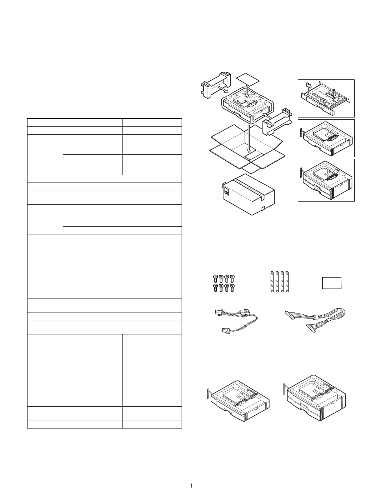
1. Unpacking
AR-D11 AR-D12
No. of stage 1-stage 2-stage
Capacity 550 pages x 1 stage
Size detection No (The paper size is set with the user program.)
Paper empty
detection
Paper feed
size
Size when
shipping
Size selection User selection (Set by the user program.)
Cassette
installation
Heater Provided only for Japan.
Power source Supplied from the copier. DC24V, power
Drive supply
(Japan)
500 pages x 1 stage
(EX Japan)
(Note) Japan: 64g/m
Provided
A3, B4, A4, A4R, B5, B5R, 16k, 16kR, 8k,
11 x 17, 8.5 x 14, 8.5 x 13, 8.5 x 11, 8.5 x 11R
AB series: A4
Inch series: 8.5 x 11
Japan: A3, B4, A4, A4R, B5, B5R, 8.5 x 11,
8.5 x 11R, 8.5 x 14, 11 x 17
Inch series: 11 x 17, 8.5 x 14, 8.5 x 11,
8.5 x 11R, A4, A3
Inch series foolscap: 11 x 17, 8.5 x 14, 8.5 x 13,
8.5 x 11, 8.5 x 11R, A4, A3
EX AB series foolscap: A3, B4, A4, A4R,
8.5 x 13, 8.5 x 14, 8.5 x 11, 11 x 17
Installed by the user.
consumption 5.6W
· When installed as the
2-stage cassette for
the 2-stage cassette
standard model:
Supplied via gears
from the copier.
550 pages x 2 stages
(Total 1, 100 pages)
(Japan)
500 pages x 2 stages
(Total 1, 000 pages)
(EX Japan)
2
, EX: 80g/m
Supplied by the
individual motor.
2
· When installed as the
optional 2-stage or 3stage cassette:
Supplied by the
individual motor.
External
dimensions
Weight About 5kg About 10kg
596(W) x 471(D) x
97(H) mm
596(W) x 471(D) x
194(H) mm
AR-D11
AR-D12
2. Installation
Parts included
Screws (M4 x 12): 8 pcs.
Relay harness
for dehumidifying heater
Remove all pieces of fixing tape and fixing mat erials from the paper
feed unit.
Fixing plates: 4 pcs.
Cassette relay harness
(contained in the optional paper feed unit)
Paper size label
Page 3
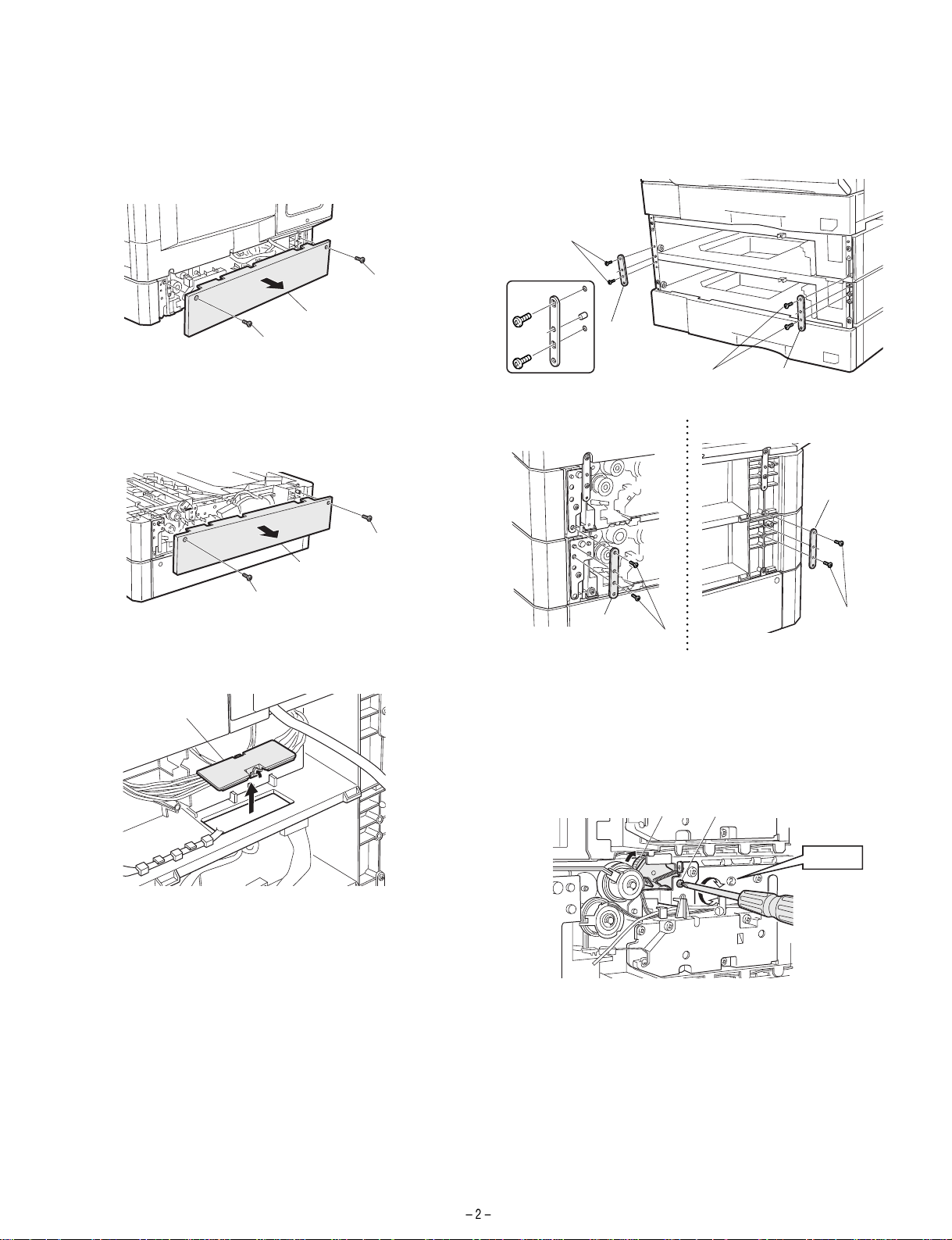
For copier models with two paper trays.
Turn off the main switch of the copier and then remove the power plug
of the copier from the outlet.
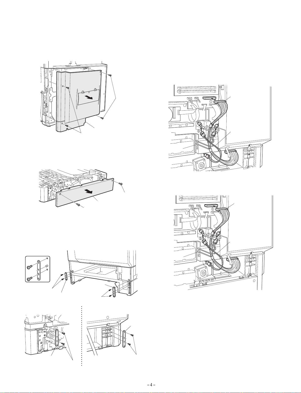
1. Remove the rear cover from the copier.
Remove the two screws and then remove the rear cover from the
copier.
4. Attach the copier
Place the copier on the optional paper feed unit and remove the
second and third paper trays.
Connect the copier to the paper feed unit using four fixing plates and
two screws (M4 x 12) for each plate.
Front side
Screws (M4 x 12)
Screw
Rear cover
Screw
2. Remove the rear cover from the optional pap er feed
unit.
Remove the two screws and then remove the rear cover from the
optional paper feed unit.
Screw
Rear cover
Screw
3. Remove the connector cover.
Remove the cover from the connector.
Connector cover
Detailed view
Fixing plate
Left of rear side
Fixing plate
Screws (M4 x 12)
Screws
(M4 x 12)
Fixing plate
Right of rear side
Fixing plate
Screws
(M4 x 12)
5. Unlock the connection gear.
<1> Loosen the screw of the connection gear and ensure that the
connection gear has moved to the optional paper feed unit.
<2> Tighten the connection gear fixing screw again.
Connection gear
Connection gear fixing screw
CAUTION
6. Connect the harness.
<1> Connect the cassette relay harness contained in the optional
paper feed unit to the paper feed unit relay PWB.
<2> Remove the relay harness for dehumidifying heater connected to
the second paper tray.
<3> Connect the relay harness for dehumidification heater contained
in the optional paper tray to the optional paper tray.
Page 4
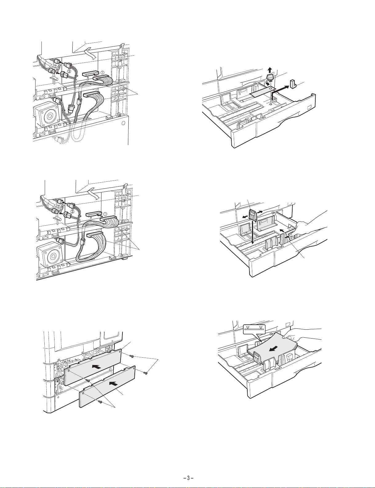
· For two tray typ e
Relay harness for
dehumidification heater
Cassette relay harness
8. Remove the securing fixture for packing the paper
feed unit and remove the packing material.
Remove the securing fixture for packing that fixes the paper pressure
plate of the tray by rotating it in the direction of the arrow and remove
the packing material.
Securing fixture for packing
Packing material
[Caution]
Be sure to remove the
securing fixture before
turning on the power.
· For one tray type
Relay harness for
dehumidification heater
Cassette relay harness
7. Attach the rear covers of the copier and the optional
paper feed unit.
Attach the rear covers of the copier and the optional paper feed unit
using two screws respectively.
9. Change the paper size in the tray.
Hold the grip and slide the cassette side plate to adjust it to the paper
to be used.
Then, fit the rear end plate to the specified size position.
Rear plate
Side plate
Insert the power plug of the copier to the out let and turn on the main
switch of the copier. Then, carry out the following procedure.
10. Load paper into the paper tray.
Do not exceed the maximum height line.
Rear cover
Screws
Rear cover
Screws
11. Check for center displacement.
· Set an original on the document glass and copy it using the paper
tray in the copier.
Then, copy an original using the attached optional paper feed unit.
· If the center of the copy image from the tray in the copier is differ-
ent from that of the copy image from the optional paper feed unit,
carry out adjustment referring to the service manual.
Installation of Paper feed unit is now complete.
Page 5
For copier models w ith one paper tray
Turn off the main switch of the copier and then remove the power plug
of the copier from the outlet.
1. Remove the right rear cover from the copier.
Remove the four screws and then remove the right rear cover from
the copier.
4. Connect the harness.
<1> Connect the cassette relay harness contained in the paper feed
unit to the MCU PWB of the copier.
<2> Remove the relay harness for dehumidifying heater connected to
the paper tray in the main unit.
<3> Connect the relay harness for dehumidification heater contained
in the optional paper tray to the optional paper tray.
<4> Store the harness in the harness holder.
· For one tray type
Screws
Right rear cover
Screws
2. Remove the rear cover from the optional pap er feed
unit.
Remove the two screws and then remove the rear cover from the
optional paper feed unit.
Screw
Rear cover
Screw
3. Attach the copier
Place the copier on the optional paper feed unit and remove the first
and second paper trays.
Connect the copier to the paper feed unit using four fixing plates and
two screws (M4 x 12) for each plate.
Harness holder
· For two tray type
Cassette relay harness
Relay harness for
dehumidification heater
Cassette relay harness
Relay harness for
dehumidification heater
Detailed view
Screws (M4 x 12)
Left of rear side
Fixing plates
Fixing plates
Screws (M4 x 12)
Fixing plates
Screws (M4 x 12)
Right of rear side
Fixing plates
Screws (M4 x 12)
Harness holder
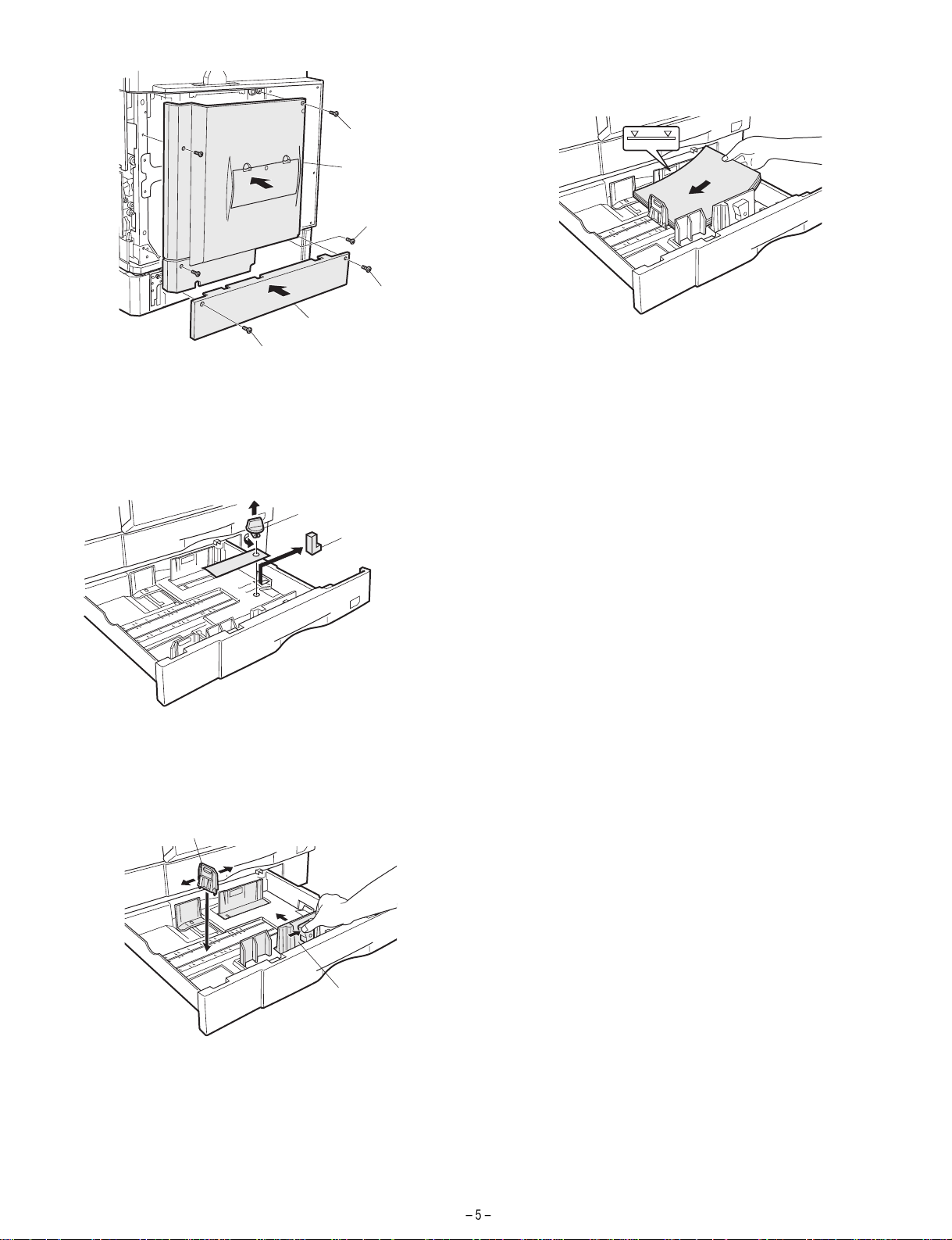
5. Attach the right rear cabinet of the copier an d the rear
cover(s) of the optional pap er fee d un it.
Attach the right rear cabinet of the copier using four screws, and
attach the rear cover(s) of the optional paper feed unit using two
screws respectively.
Page 6
Screw
Right rear cabinet
Screw
Screw
Rear cover
Screw
6. Remove the securing fixture for pac ki ng the pa pe r
feed unit and remove the packing material.
Remove the securing fixture for packing that fixes the paper pressure
plate of the tray by rotating it in the directi on of the arrow and remove
the packing material.
Securing fixture for packing
Packing material
8. Load paper into the paper tray.
Do not exceed the maximum height line.
9. Check for center displacement.
· Set an original on the document glass and copy it using the paper
tray in the copier.
Then, copy an original using the attached optional paper feed unit.
· If the center of the copy image from the tray in the copier is differ-
ent from that of the copy image from the optional paper feed unit,
carry out adjustment referring to the service manual.
Installation of Paper feed unit is now complete.
[Caution]
Be sure to remove the
securing fixture before
turning on the power.
7. Change the paper size in the tray.
Hold the grip and slide the cassette side plate to adjust it to the paper
to be used.
Then, fit the rear end plate to the specified size position.
Rear end plate
Side plate
Insert the power plug of the copier to the outlet and turn on the main
switch of the copier. Then, carry out the following procedure.
Page 7

[4] EXTERNAL VIEW AND INTERNAL STRUCTURE
1. External view
1
AR-D12 AR-D11
No. Name No. Name
1 Paper feed tray 2 Paper feed right cover
2. Internal structure
12
15
16
17
14
1
2
2
1
2
3
4
5
6
13
4
7
8
9
18
10
11
Motors, sensors, solenoids, etc.
No. Code Name Type Function/Operation Remark
1 PWB Interface PWB –
2 Drive motor Hybrid Drives gears.
3 LUM1AD Lift-up motor (No. 1 tray)
4 /PCLIA Paper feed clutch Electromagnetic clutch Rotates the paper feed roller.
5 TRCLA Transport clutch Electromagnetic clutch Rotates the transport roller.
6 CSS1 Cassette detection SW Contact Detects cassette empty.
7 CSS2 Cassette detection SW Contact Detects cassette empty. AR-D12 only
8 LUM2B Lift-up motor (No. 2 tray)
9 /PCS1B Paper feed solenoid DC solenoid Feeds paper.
10 DRS1 Door open/close detection SW Contact Detects door open/close.
11 DRS2 Door open/close detection SW Contact Detects door open/close. AR-D12 only
12 PAP1 Paper empty sensor Photo transmission Detects paper empty in the cassette.
13 LUD1 Upper limit sensor Photo transmission Detects the upper limit for paper pickup.
14 PPD1 Paper entry sensor Photo transmission Detects paper transport.
15 PAP2 Paper empty sensor Photo transmission Detects paper empty in the cassette. AR-D12 only
16 LUD2 Upper limit sensor Photo transmission Detects the upper limit for paper pickup. AR-D12 only
17 PPD2 Paper empty sensor Photo transmission Detects paper transport. AR-D12 only
18 /PCS2 Paper feed solenoid DC solenoid Feeds paper. AR-D12 only
Page 8

[5] OPERATIONAL DESCRIPTIONS
1. Paper transport path
[6] DISASSEMBLY AND ASSENBLY
For disassembly, follow instructions of illustrations 1, 2, 3, ... in this
sequence. For assembly, reverse the disassembly procedures.
For replacement of parts described in this manual, refer to the Parts
Guide.
1. Paper feed solenoid
1-1
2. Operational descriptions
The operations of this unit is controlled by the copier, and the pickup
roller, the paper feed roller, etc. are driven by the drive motor.
Paper picked up by the pickup roller is transported by the paper feed
roller, detected by the paper entry sensor, and fed to the resist roller.
6
5
4
3
2
1
5
4
3
2
1
1-2
1-3
1)
1)
2)
2)
No. Part name Operation
1 Pickup roller Picks up paper.
2 Paper feed roller Transports paper.
3 Separation sheet Press paper to the paper feed
roller.
4 Paper entry detection ACT Detects transport of paper.
5 Paper entry sensor Detects transport of paper.
6 Resist roller Synchronizes the paper lead
edge and the image lead edge.
1)
3)
Page 9

2. Paper feed rollers
Reference : Illust (1-1)
2-1
3-A-2
1)
3)
4)
4)
3. Motors, clutches, belts
3-1
2)
1)
B. Lift-up motor
3-B-1
2)
3-5
1)
3)
2)
2)
2)
1)
3)
2)
2)
2)
A. Drive motor
3-A-1
1)
1)
1)
3)
2)
C. Paper feed clutch / Transport clutch
3-C-1
1)
1)
1)
3)
3)
2)
3)
2)
1)
2)
3)
Page 10

D. Belt
Reference : Illust (1-1)
3-D-1
3)
2)
1)
3-D-2
3)
6)
5)
4)
3)
2)
[7] MAINTENANCE
No. Name Work item When service call
1 Pickup roller Cleaning
2 Paper feed roller Cleaning
1)
Page 11

[8] ELECTRICAL SECTION
1. Block diagrams
Copier
(MCU PWB)
CSSEL(A,B,C)
Y2
2
(PCL,PCS,LUM)
AI,BI,/AI,/BI
OPCASSEL
Y1B
1B
(PCL,PCS,
TRCL,LUM)
Y1A
1A(PCL,PCS,
TRCL,LUM)
DATA
SELECTOR
5V
DATA
SELECTOR
TRANSISTOR
ARRAY
24V
MOTOR
DRIVER
CASSETTE INTERFACE PWB
DATA
SELECTOR
PPD1B
PAP1B
LUD1B
DRS1B
CSS1B
24V
/PCL1B
/PCS1B
/TRCLB
LUM1BD
MOTOR
(A,/A,B,/B)
24V
PPD1B
PAP1B
LUD1B
5V
5V
PPD2
PAP2
LUD2
DRS2
CSS2
/PCL2
/PCS2
LUM2D
24V
5V
:MULTI CASSETTE LOWER
5V
DRS1B
CSS1B
DATA
SELECTOR
/PCL1B
TRANSISTOR
ARRAY
/PCS1B
/TRCLB
24V
LUM1BD
MOTOR
DRIVER
CASSETTE INTERFACE PWB
:OPTION 2nd CASSETTE or MULTI CASSETTE
24V
MOTOR
(A,/A,B,/B)
24V
5V
PPD2
PAP2
LUD2
DRS2
CSS2
/PCL2
/PCS2
LUM2D
24V
Page 12

D
C
B
A
12345678
1
2
179228-2(AMP)
PHR-3
PL
GL
123
MULTI CASSETTE (UPPER)
CASSETTE INTERFACE PWB
FG
SRA-01T-3.2
SRA-21T-4
PULSE
MOTOR
PHR-5
3BI
2/AI
524V1
4/BI
1AI
CN6(B5B-PH-K-S)
+24V
+24V
PGND
1A
2A
20B
CN9(53314-1015)
GL
GL
RD
RD
Sensor PWB
SGND
1
B6B-PH-K-S
GLORPKLBBR
PHR-6
PHR-8
GLBRORPKLB
1
CN8(B8B-PH-K-S)
SGND
PGND
SGND
18B
19B
GL
GL
DRS
HPIN
SGND
B3B-PH-K-S
PPD1H:Paper entry sensor
LUD1H:Lift-up upper
limit sensor
HDRS:Door sensor
PAP1H:
PPD
LUD
PAP
+5V
DRS1
26543
BR
BR
BR
RD
7
4
LUD1
/PCS1B
PAP13PPD1 26SGND5+5V
DRS1
+3.3V
SGND
+5V3A+5V4A+3.3V
SGND
5A
6A
16B
17B
15B
BL
BL
GL
GL
GL
OR
OR
8+24V
PGND
7A
LUM2#
14B
PK
Paper feed
clutch
Paper feed
solenoid
BR
BR
1
2
SMR-02V-N(RD)(JST)
1
2
BR
RD
SMP-02V-NC(RD)(JST)
PHR-3
PLPLLB
3
1
N.C. 2
/PCL1A
+24V
CN3(B3B-PH-K-S)
PCL2#
LUM1B#
TRCLB#
Y2
CSSELA#
Y1B
Y1A
PCS2#
8A
11A
10B
12B9A10A
13B
11B
PL
LB
LB
PL
PK
PK
BR
BR
BR
HPR-3(BK)
1
TRCLA
CN2(B3B-PH-K-K(BK))
CSSELC#
PCS1B#
9B
12A
PL
LB
N.C. 2
CSSELB#
13A
LB
PK
3
+24V
CN1(B3B-PH-K-R(RD))
PCL1B#
BI#
8B
14A
BR
123
LB
PHR-3
PHR-3(RD)
LB
1
LUM1AD
AI#
7B
PL
Lift-up motor
Cassette
detection
1
2
179228-2(AMP)
GL
PL
GL
PHR-3(BL)
GL
PL
GL
3
3
1
N.C. 2
CSS1
SGND
N.C. 2
PGND
CN7(B3B-PH-K-B(BL))
OPCASSEL#
/BI#
/AI#
LUM1A#5B
+24V17A
TRCLA#4B
+24V18A
PCS1A#3B
PGND19A
PCL1A#2B
PGND20A
6B
15A
16A
LB
PL
LB
PK
BR
RD
SGND1B
PK
GL
GL
GL
BR
RD
1
2
179228-2(AMP)
PHR-3
LB
GL
123
DRS
HPIN
SGND
B3B-PH-K-S
Sensor PWB
PAP1H:
LUD1H:Lift-up upper
limit sensor
PPD1H:Paper entry sensor
DRS:Door sensor
PPD
LUD
HPIN
PAP
+5V
SGND
1
26543
B6B-PH-K-S
GLORPKLBBR
BR
PHR-6
PHDR-14VS
GLORPKLBBRBRRDPLRD
PL
GL
3+5V
2PPD2
6
5DRS2
7
4PAP2
1SGND
PGND
LUD2
CSS2
CN4(B14B-PHDSS-B)
CN5(53314-1015)
9108
+24V
/PCL2
Cassette
detection
1
2
Paper feed
clutch
179228-2(AMP)
PL
GL
Lift-up motor
Paper feed
solenoid
321
GL
LB
PHR-3
BR
BR
PL
PL
1
2
1
2
SMR-02V-N(RD)(JST)
11
+24V
BR
12
/PCS2
SMR-02V-B(JST)
1
2
1
2
RD
BR
RD
PL
SMP-02V-BC(JST)
SMP-02V-NC(RD)(JST)
GL
LB
14
13PGND
LUM2D
MULTI CASSETTE (LOWER)
2 1
3
MULTI CASSETTTE
1
2
179228-2(AMP)
SENSOR PWB
SGND
B6B-PH-K-S
1
GLORPKLBBR
PHR-8 PHR-6
GLBRORPKLBBRBR
1
CN8(B8B-PH-K-S)
SGND
SGND
SGND
17B
18B
GL
GL
GL
GL
GL
GL
SGND
SGND
SGND
17B
18B
PPD1H:Paper entry sensor
PPD
26543
BR
5A
OR
OR
ORORBL
5A
B3B-PH-K-S
PAP1H:
PAP
+5V
4
PAP13PPD1 26SGND5+5V
+5V3A+5V4A+3.3V
6A
16B
BL
+5V3A+5V4A+3.3V
6A
16B
PHR-3
PL
BL
BL
123
DRS
DRS:Door sensor
DRS1
DRS1
+3.3V
15B
GL
GL
+3.3V
15B
GL
HPIN
SGND
LUD1H:Lift-up upper
limit sensor
LUD
RD
7
LUD1
/PCS1A
LUM2#
PGND
7A
14B
PK
BR
PK
BR
LUM2#
PGND
7A
14B
8+24V
Y1A
8A
PL
PL
Y1A
8A
2nd CASSETTE
FG
SRA-01T-3.2
OPTION 2nd CASSETTE ONLY
SRA-21T-4
PLUSE
MOTOR
PHR-5
3BI
2/AI
524V1
4/BI
1AI
CN6(B5B-PH-K-S)
+24V
+24V
PGND
PGND
CASSETTE INTERFACE PWB
1A
2A
20B
19B
CN9(53314-1015)
GL
GL
GL
RD
RD
51089-4005
GLRDRD
GL
GL
+24V
+24V
PGND
PGND
1A
2A
20B
19B
SGND
SGND
MCU PWB
2. Actual wiring diagram
PCS2#
13B
LB
LB
PCS2#
13B
Lift-up motor
Cassette
detection
123
1
1
N.C. 2
LUM1AD
OPCASSEL#
/AI#
6B
16A
BR
/AI#
OPCASSEL#
6B
16A
GL
GL
3
PGND
LUM1A#5B
PL
RD
PLRDBRGLLB
LUM1A#5B
+24V17A
+24V17A
PL
PHR-3(BL)
PL
CN7(B3B-PH-K-B(BL))
TRCLA#4B
LB
RD
TRCLA#4B
2
179228-2(AMP)
GL
GL
3
1
N.C. 2
CSS1
SGND
+24V18A
PCS1A#3B
PGND19A
PK
GL
PKBRRDGLGL
+24V18A
PCS1A#3B
PGND19A
51089-4005
GLRDRD
ORORBL
GL
GL
GL
GL
GL
5A
2A
1A
20B
19B
+24V
+24V
PGND
PGND
CN5(53314-1015)
SGND1B
PCL1A#2B
PGND20A
GL
GL
BR
SGND1B
PCL1A#2B
PGND20A
6A
16B
17B
18B
SGND
+5V3A+5V4A+3.3V
SGND
SGND
SGND
PK
PK
BL
GL
BR
LB
PL
8A
7A
15B
14B
13B
12B9A10A
PCS2#
+3.3V
LUM2#
PGND
Y1B
PCL2#
Y2
N.C.
PK
PL
LB
11A
11B
N.C.
CSSELA#
PKBRBR
CN4(B14B-PHDSS-B)
10B
N.C.
PL
9B
12A
N.C.
CSSELC#
1SGND
2 PPD2
8B
13A
N.C.
CSSELB#
3+5V
4 PAP2
PLLBBR
PK
LB
7B
15A
14A
/BI#
BI#
AI#
PGND
LUD2
6
5DRS2
7
6B
/AI#
CSS2
16A
OPCASSEL#
PLRDBRGLLB
+24V
9108
LUM1B# 5B
/PCL2
+24V 17A
+24V
11
TRCLB# 4B
/PCS2
12
+24V 18A
13 PGND
PKBRRDGLGL
PCS1B# 3B
PGND 19A
PCL1B# 2B
PGND 20A
LUM2D
14
SGND 1B
2nd CASSETTTE
Paper feed
clutch
Paper feed
solenoid
SMR-02V-N(RD)(JST)
BR
BR
1
2
1
2
BR
RD
SMP-02V-NC(RD)(JST)
PHR-3
PL
1
N.C. 2
/PCL1A
CN3(B3B-PH-K-S)
PCL2#
LUM1B#
TRCLB#
Y2
CSSELA#
CSSELC#
Y1B
12B9A10A
11A
10B
12A
11B
PL
LB
PK
PK
BR
BR
PK
PL
PKBRBR
LB
Y1B
PCL2#
LUM1B#
TRCLB#
Y2
CSSELA#
CSSELC#
12B9A10A
11A
10B
12A
11B
PL
3
+24V
PCS1B#
9B
PL
PL
PCS1B#
9B
HPR-3(BK)
LB
1
TRCLA
CN2(B3B-PH-K-K(BK))
PCL1B#
CSSELB#
8B
13A
LB
PK
PK
PCL1B#
CSSELB#
8B
13A
LB
PHR-3
PHR-3(RD)
LB
LB
3
N.C. 2
+24V
CN1(B3B-PH-K-R(RD))
/BI#
BI#
AI#
7B
15A
14A
PL
LB
PK
BR
PK
PLLBBR
LB
/BI#
BI#
AI#
7B
14A
15A
8 7 6 5 4
D
C
B
A
Page 13

D
C
CSS1
PPD1
DRS1
PAP1
LUD1
B
PPD2
PAP2
CSS2
DRS2
LUD2
A
12345678
Multi Cassette Only
2200pF/50Vx5
10Kx7
R37
3.3V
R41 R40R42R43
R39 R38
C35
C38 C37C39C40
JP2 JP1
JP1 MOTOR L MOTOR
JP2 1, 2 Cassette L 1 Step
10Kx5
3.3V
R15R13 R12
R14 R16
C9C12
C13
C11
C10
(QS53)
2200pF/50Vx6
2 1
Option Cassette Only
(QS52,QS53)
(2-1A)
AIBI24V1
/BI
/AI
F2
ICP-N38
47uF/35V
C1
+
0.047uF/50V
C18
24V
R23
7.5K
C22
2200pF/
7.5K
R31
C31
2200pF/50V
0.047uF/50V
C19
10
18
1
Vmm
OUT A
OUT B
CrA2CrB26VsA4RsA9VrefA3VrefB25RsB19VsB24In /A5In A6In /B23In B
IC2
R20
1K
50V
C20
3300pF/50V
C33
0.1uF/25V
R3 1.5(1W)
R33 2.4k
R32
1.5kF
8
OUT /A
20
OUT /B
R36 2.4k
NC17NC16NC15NC14NC12NC
R22
1K
C34
R4 1.5(1W)
11
27
PG7PG13PG21LG
MTD1361
22
C21
3300pF/50V
0.1uF/25V
R34
430F
AI#
BI#
/AI#
/BI#
C36
0.1uF/25V
IC5
16
PCL1A#
R29 1.5K
R30 1.5K
I11I22I33I44I55I66I7
IC1
COM
O116O215O314O413O512O611O7
9
24V
D04D13D22D31D415D514D613D7
VCC
W6Y
5
Y1A
PCL2#
LUM1A#
TRCLA#
PCS1A#
PCS2#
R25 1.5K
R27 1.5K
R28 1.5K
R26 1.5K
12
7
G
74HC151AF
GND
A11B10C
8
9
1Kx3
R17
R18
R19
CSSELB#
CSSELA#
CSSELC#
LUM2#
R24 1.5K
7
8
GND
TD62001
10
C7
0.047uF/50V
C8
0.047uF/
UDZS3.9B
ZD2
UDZS3.9B
ZD3
UDZS3.9B
ZD1
50V
C26
0.1uF/25V
IC4
16
D04D13D22D31D415D514D613D7
VCC
W6Y
5
Y2
12
7
G
74HC151AF
GND
A11B10C
8
9
C24
C25 C23
3
1000pF/50Vx3
C32
0.1uF/25V
R35
2.4KF
1
VOUT
IC3
KIA78S05P
VIN
3
R5
3. Interface PWB circuit diagram (1/2)
24V
C5
10uF/16V
GND
2
C6
10uF/35V
R6
3.6K 1/4W
3.6K 1/4W
D
Q5
DTC143ZKA
47k
4.7k
OPCASSEL#
C
R11
10k
R2
24V
/PCL2
/PCS2
/PCL1A
/TRCLA
/PCS1A
1.5k(1/2W)
F3
ICP-N38
5
6
3
Q4
IMZ4
LUM1AD
Q3
2
DTC114EKA
1 3
R10
1.5k
2
R21
47
4 1
Multi Cassette Only
24V
(QS53)
B
R7
10k
R1
1.5k(1/2W)
F1
ICP-N38
5
6
Q2
IMZ4
LUM2D
2
Q1
DTC114EKA
1 3
R8
1.5k
2
R9
47
4 1
3
8 7 6 5 4
A
Page 14

D
C
LUM2#
B
PCS2#
PCL2#
LUM1B#
PCS1B#
PCL1B#
AI#
/AI#
TRCLB#
A
12345678
Option Cassette Only
CN7
123
123
CN1
B3B-PH-K-E(BL)
LUM1AD/TRCLA
B3B-PH-K-R(RD)
3.3V
5V
246
8
101214161820222426283032363438
CN5
1357911131517192123252729
4
•¢
3133353739
C17
C16
40
B40B-PADKS-1
7
3
•¢
•¢
0.1uF/25V
0.1uF/25V
(QS51,QS52)
NOTE
QS51:STANDARD 2ND CASSETTE
QS52:OPTION 2ND CASSETTE
QS53:OPTION MULTI CASSETTE
2 1
3
5V 3.3V
123
CN3
24V
/PCL1A CSS1
246
8
CN9
1357911131517192123252729
123
B3B-PH-K-S
LUM2#
PCS2#
PCL2#
101214161820222426283032363438
CN2
LUM1B#
TRCLB#
PCS1B#
PCL1B#
AI#
/AI#
B3B-PH-K-K(BK)
TRCLA#
PCS1A#
3133353739
PCL1A#
C15
0.047uF/50V
24V
C14
Y2
BI#
LUD2
/BI#
CSSELA#
CSSELB#
CSSELC#
OPCASSEL#
CSS2
/PCL2
/PCS2
LUM2D
8
101214
B14B-PHDSS-B
0.047uF/50V
Option Cassette Only
(QS52,QS53)
CN8
5V
12345
CN6
AI
BI
/AI
1234567
B5B-PH-K-S
/BI
24V1
8
B8B-PH-K-S
Y1B
C30
0.1uF/25V
+
C3
10uF/16V
C29
0.1uF/25V
+
C4
10uF/16V
Multi Cassette Only
40
B40B-PADSS-1
7
•¢3•¢
(QS53)
5V
PPD2
PAP2
246
135791113
CN4
C2
47uF/35V
+
F4
ICP-N50
24V
BI#
3. Interface PWB circuit diagram (2/2)
Y1AY2Y1B
/BI#
CSSELB#
CSSELA#
CSSELC#
OPCASSEL# LUM1A#
D
C28
0.047uF/50V
C27
0.047uF/50V
C
24V
DRS2
24V
PAP1
LUD1
PPD1
DRS1
/PCS1A
B
A
8 7 6 5 4
Page 15
D
C
B
A
12345678
2 1
12345
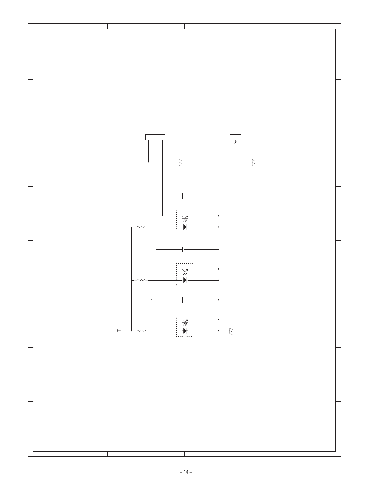
PPD
6
S6B-PH-K-S
PAP
LUD
DRS
CN1
123
CN2
S3B-PH-K-S
DRS
3
5V
C3
102pF
PT3
GP1S58V
R3
220J/ 1/4W
Upper limit
C2
102pF
PT2
GP1S58V
R2
220J/ 1/4W
C1
102pF
PT1
GP1S58V
R1
5V
220J/ 1/4W
4. Sensor PWB circuit diagram
D
8 7 6 5 4
C
B
A
Page 16

5. Parts layout
1) Cassette interface PWB
a. Parts surface
CN3 (B3B-PH-K-S)
3 +24V
2 N.C.
1 /PCL1A
CN4 (B14B-PHDSS-B)
13 PGND
11 +24V
9 +24V
7 PGND
5 DRS2
3 +5V
1 SGND
14 LUM2D
12 /PCS2
10 /PCL2
8 CSS2
6 LUD2
4 PAP2
2 PPD2
CN2 (B3B-PH-K BL)
3 +24V
2 N.C.
1 TRCLA
CN1 (B3B-PH-K-R RD)
3 PGND
2 N.C.
1 LUM1AD
CN6 (B5B-PH-K-S)
5 24V1
4 /B1
3 B1
2 /A1
1 A1
CN7 (B3B-PH-K BL)
3 SGND
2 N.C.
1 CSS1
CN8 (B8B-PH-K-S)
8 +24V
7 /PCS1B
6 LUD1
5 DRS1
4 PAP1
3 +5V
2 PPD1
1 SGND
CN5 (53314-1015) CN9 (53314-1015)
2 +24V
4 PGND
6 SGND
8 SGND
10 +5V
12 +3.3V
14 LUM2#
16 PCS2#
18 PCL#
20 N.C.
22 N.C.
24 N.C.
26 N.C.
28 A1#
30 /A1#
32 LUM1B#
34 TRCLB#
36 PCS1B#
38 PCL1B#
40 SGND
1 +24V
3 PGND
5 SGND
7 SGND
9 +5V
11 +3.3V
13 PGND
15 Y1B
17 N.C.
19 Y2
21 CSSELA#
23 CSSELC#
25 CSSELB#
27 B1#
29 /B1#
31 OPCASSEL#
33 +24V
35 +24V
37 PGND
39 PGND
2 +24V
4 PGND
6 SGND
8 SGND
10 +5V
12 +3.3V
14 LUM2#
16 PCS2#
18 PCL2#
20 LUM1B#
22 TRCLB#
24 PCS1B#
26 PCL1B#
28 A1#
30 /A1#
32 LUM1A#
34 TRCAL#
36 PCS1A#
38 PCL1A#
40 SGND
1 +24V
3 PGND
5 SGND
7 SGND
9 +5V
11 +3.3V
13 PGND
15 Y1A
17 Y1B
19 Y2
21 CSSELA#
23 CSSELC#
25 CSSELB#
27 B1#
29 /B1#
31 OPCASSEL#
33 +24V
35 +24V
37 PGND
39 PGND
Page 17

b. Solder surface
2) Cassette sensor PWB
a. Parts surface b. Solder surface
CN1 (S6B-PH-K-S)
6 LUD
5 DRS
4 PAP
3 5V
2 PPD
1 SGND
3 DRS
2 N.C.
1 SGND
Page 18

(For USA,CANADA)
CAUTION FOR BATTERY DISPOSAL
Contains lithium-ion battery. Must be disposed of properly.
Remove the battery from the product and contact
agencies for information on recycling and disposal options.
federal or state environmental
Page 19

Symbol/PartsCod)
- - - - - - - - - - - - - - - - - - - - - - - - - - - - - - - - - - - - - - - - - - - - - - - - - - - - - - -
COPYRIGHT ã 2001 BY SHARP CORPORATION
All rights reserved.
Printed in Japan.
No part of this public ation may be reproduced,
stored in a retrieval system, or transmitted.
In any form or by any means ,
electronic, mechanical, photocop ying, recording, or oth erwise,
without prior written permission of the publisher.
SHARP CORPORATION
Digital Document Systems Group
Quality & Reliability Control Center
Yamatokoriyama, Nara 639-1186, Japan
2001 April Printed in Japan
 Loading...