

Page 1
AR-DU2
CODE : 00ZARDU2//A1E
DIGITAL COPIER OPTION
DUPLEX MODULE
MODELAR-DU2
CONTENTS
[1] UNPACKING AND INSTALLATION . . . . . . . . . . . . . . . . . . . . . . . . . 1
[2] EXTERNAL VIEW AND INTERNAL STRUCTURE . . . . . . . . . . . . . 8
[3] DESCRIPTION OF OPERATIONS . . . . . . . . . . . . . . . . . . . . . . . . . 9
[4] DISASSEMBLY, ASSEMBLY, MAINTENANCE . . . . . . . . . . . . . . 12
[5] ADJUSTMENTS . . . . . . . . . . . . . . . . . . . . . . . . . . . . . . . . . . . . . . . 15
[6] ELECTRICAL SECTION . . . . . . . . . . . . . . . . . . . . . . . . . . . . . . . . 17
This document has been published to be used
for after sales service only.
The contents are subject to change without notice.
Page 2
AR-DU2
[1] UNPACKING AND INSTALLATION
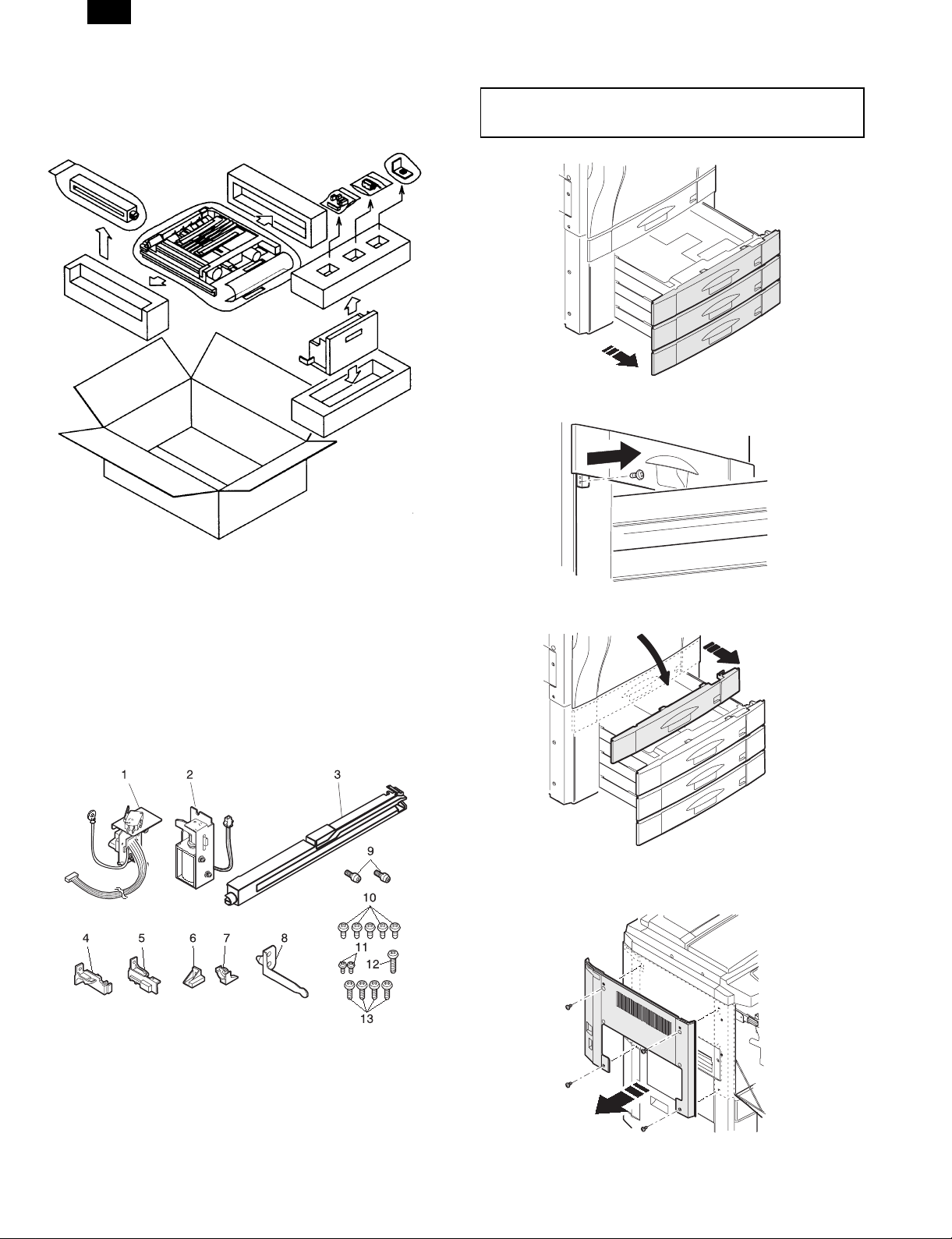
1. Unpacking
3. Installation
Disconnect the plug of the copier and follow the
following procedures.
1) Pull out paper trays No. 2 through No. 4 from the copier.
2) Remove the securing screw (1 screw) that secures the No. 1
paper tray.
2. Parts list
1 Drawer unit 1 8 Decurler securing plate As 1
2 AG solenoid unit 1 9 Positioning pin 2
3 Relay PG 1 Securing screws
4 ADU stopper L 1 10 Securing screw A M4x8 S tight 5
5 ADU stopper R 1 11 Securing screw B M3x6 S tight 2
6 Tray stopper right 1 12 Securing screw C M4x14 P tight 1
7 Tray stopper left 1 13 Securing screw D M4x10 P tight 4
3) Openthe front cabinet of the copier.
4) Remove the paper tray cover.
5) Pull out the toner hopper unit.
6) Remove the securing screws (4 screws) that secure he left upper
cabinet to the copier and remove the left upper cabinet.
– 1 –
Page 3
AR-DU2
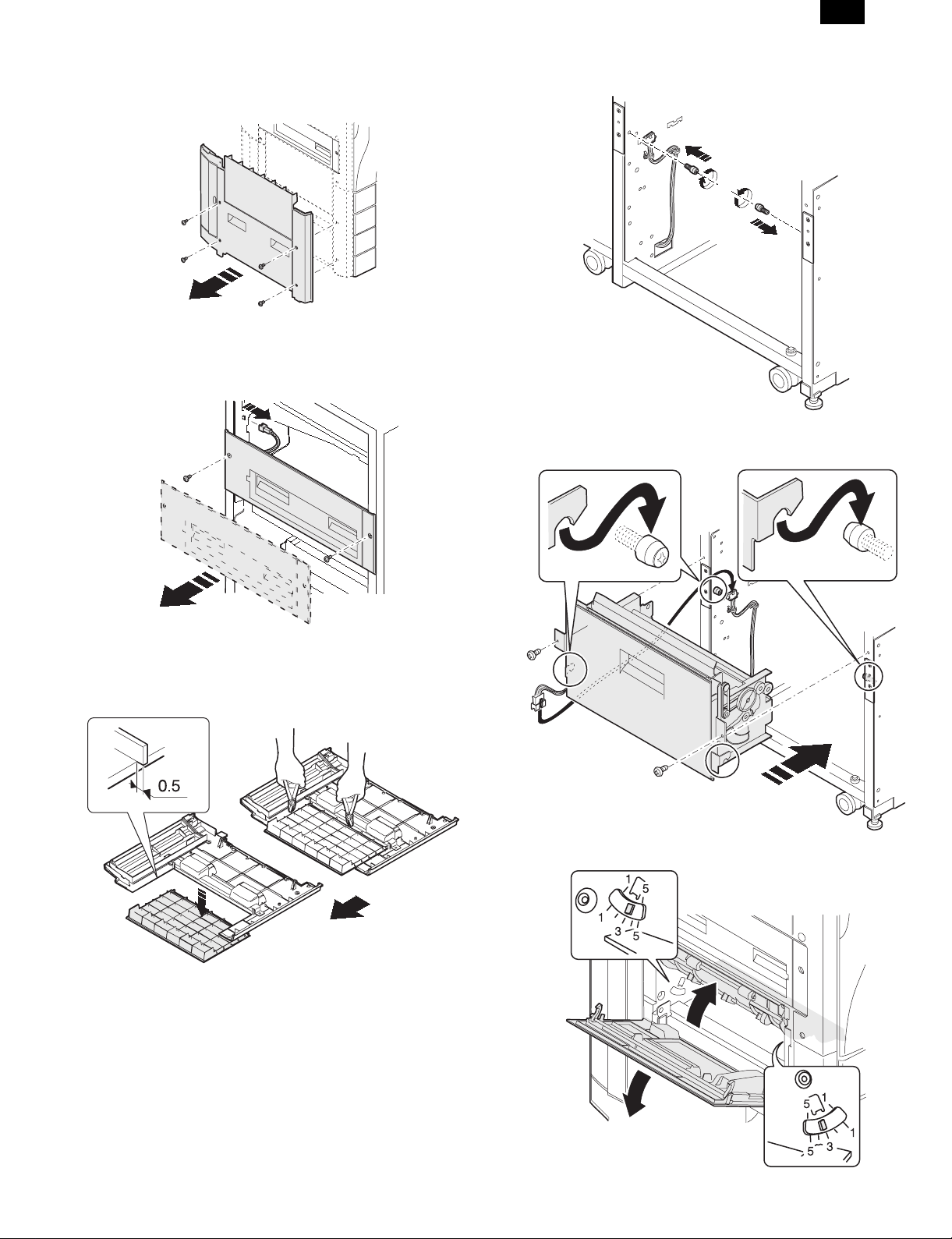
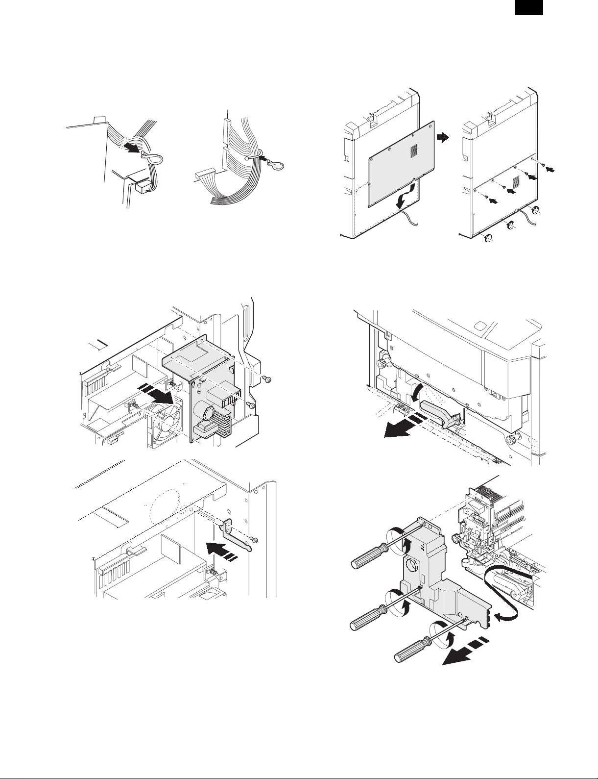
7) Remove the securing screws (4 screws) that secure the left lower
cabinet to the copier and remove the left lower cabinet.
8) Remove the connector connecting the paper exit unit to the copier.
Remove the securing screws (2 screws) that secure the paper exit
unit to the copier and remove the paper exit unit.
10) Attach the positioning pins (2 pins) to allocate positions in the
copier frame.
11) Place the left and right decurler frames on the positioning pins and
secure with securing screws A (2 screws).
Connect the decurler harness and TFD harness connectors.
9) Cut out the portion of the left lower cabinet along the provided
cut-outs.
∗ After cutting out the portion, file down the projections that remain.
∗ The cut out portion is not used.
12) Open the open/close PG and make sure that the curl adjustment
arm is set to the standard adjustment position of "3".
– 2 –
Page 4
AR-DU2
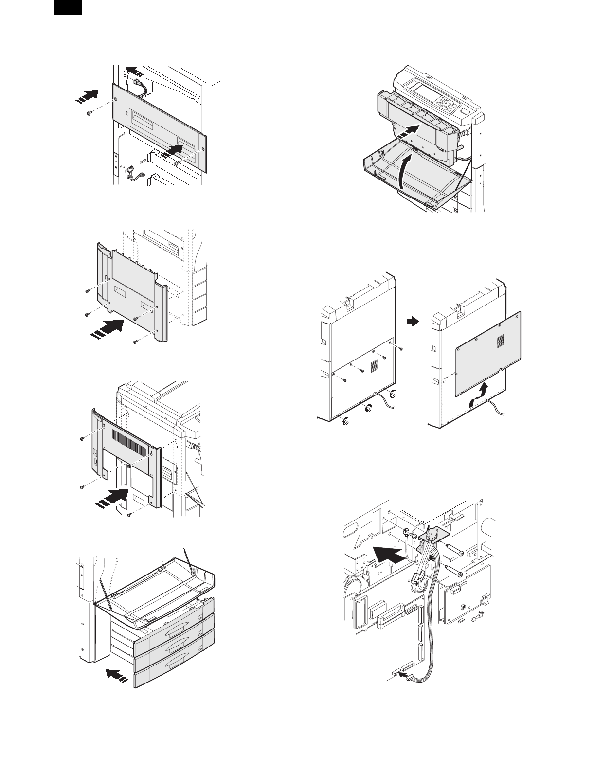
13) Install the paper exit unit and secure with the securing screws (2
screws). Connect the paper exit unit connector.
14) Install the left lower cabinet and secure with the securing screws
(4 screws).
17) Push the toner hopper back to its original position and close the
front cabinet of the copier.
18) Of the securing screws (7 screws) that secure the rear lower
cabinet of the copier, loosen the lower 3.
Then remove the upper 4 screws and then slide the rear lower
cabinet upward and remove.
15) Install the left upper cabinet and secure with the securing screws
(4 screws).
16) Push back the paper tray No. 2 through No. 4 to their original
position.
19) Install the drawer unit and secure with the supplied drawer
installation screws (2 screws).
Connect the drawer unit connector to the PCU main PC board.
Connect the drawer unit ground terminal to the securing screw A
(1 screw).
– 3 –
Page 5
AR-DU2
Remove the clamp holding together the main harness R connector
wires.
Connect the main harness R connector to the supplied
microswitch for the drawer unit.
Using the clamp removed above, clamp together the drawer unit
harness and main harness R as shown in the figure below.
20) Remove the securing screws (2 screws) and PC board supports
(2 locations) holding the scanner lamp control PWB and open the
scanner lamp control PWB.
Insert the decurler securing plate (1 piece) into the positioning hole
and secure with the securing screw A (1 screw).
Return the scanner lamp control PWB to its original position and
secure with the securing screws (2 screws) and PC board
supports (2 locations).
21) Attach the rear lower cabinet to copier by sliding it downward onto
the lower 3 securing screws.
Then install the upper 4 securing screws and tighten all securing
screws (7 screws).
22) Open the front cabinet of the copier and lower the lift handle to the
left.
Then slower pull out the transfer unit.
Loosen the securing screws (blue, 3 screws) securing the fuser
unit front cover until they spin freely.
– 4 –
Page 6
AR-DU2
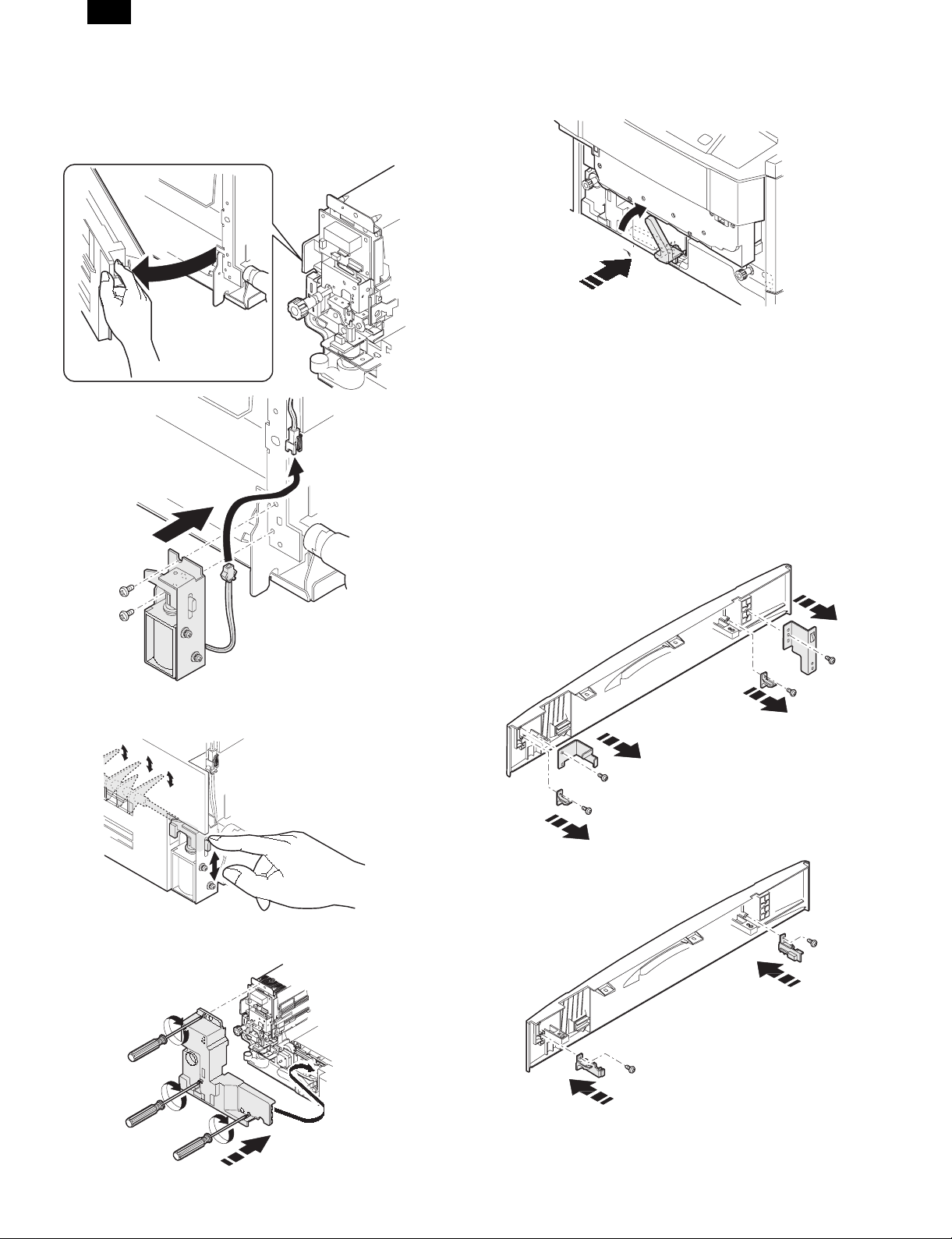
23) Open the reverse unit of the fuser unit.
Then install the gate solenoid unit and secure it with securing
screws B (2 screws).
∗ Make sure that wires of the harness do not get caught.
Connect the gate solenoid connector to the connector locked to
the reverse unit.
26) Insert the transfer unit back to its original position.
Then return the lift handle back to its original position.
Close the front cabinet of the copier.
27) Remove the screws (1 screw each) securing the front and rear tray
cover plates attached to the paper tray covers and remove the tray
cover plates.
∗ These will not be used.
Remove the screws (1 screw each) securing the tray tabs
attached to the paper tray cover and remove the tabs.
∗ The tray tabs will not be used. The securing screws will be used
as follows.
Install the ADU stopper L and secure with the securing screw (1
screw).
Install the ADU stopper R and secure with the securing screw (1
screw).
∗ Use the securing screws that were used to attach the tray tabs
above.
24) Close the reverse unit of the fuser unit.
∗ At this time, move the solenoid plunger by hand and make sure
that the gate does not get caught.
25) Install the fuser unit front cover and secure it with the securing
screws (blue, 3 screws) that are attached to the fuser unit front
cover.
– 5 –
Page 7

28) Change the paper size sign attached to the paper tray handle to
"duplex".
Attach the paper tray handle to the ADU unit and secure with
securing screw D (4 screws).
AR-DU2
30) Lift up both sides of the ADU unit, align the ADU unit with the tray
rails, and push into the copier along the tray rails.
∗ At this time, make sure that the ADU unit moves smoothly along
the tray rails.
∗ At this time, make sure that all adjuster locations (4 locations)
are set to the center markings (see figure below).
29) Insert the positioning boss of the relay paper guide into the
positioning hole of the R frame of the copier.
Then, insert the lower hook of the front side and then attach the
upper hook.
∗ At this time, make sure that the hooks are properly attached.
4. Confirming Operation, Setting, and
Adjusting
Connect the power plug of the copier to the power
outlet, turn on the power switch, and follow the
following procedures.
(1) Setting
1) Enter the simulation option setting mode.
P C26 1
2) At the DUP/CST item, select "AR-DU2".
3) Press the CA key, and cancel the set mode.
(2) Stacking ability adjustment and verification
1) Enter the simulation stacking ability adjustment mode.
P C52 1
2) Select "F" with the [ ↑ ] and [ ↓ ] keys on the operation panel.
3) Enter the number of the paper feeder section set at A4/LT and press
the EXECUTE key.
With the above key operation, A sheet of paper is fed from the paper
feed section and transported to the alignment guide of the ADU unit
and stopped at the aligned state.
– 6 –
Page 8

AR-DU2
∗ "F" tray number list
No. Tray Setting item
1 Manual MANUAL A
2 Tray 1 CAS1 B
3 Tray 2 CAS2 C
4 Tray 3 CAS3 D
5 LCC LCC E
4) Pull out the ADU unit.
5) Check that the clearance between the alignment guide and the
paper is 0 to 5 mm.
At this time, be sure to shift the paper to the rear side of the
alignment guide.
✩When the alignment guide is not shifted
After the adjustment, remove the paper from the ADU unit, press the
CA key, and cancel the set mode.
✩When the alignment guide is shifted
1) Insert the ADU unit.
2) Select the paper feed section ("A" to "E") set at A4/LT with the [ ↑ ]
and [ ↓ ] keys on the operation panel .
3) Change the set value.
C
Set value
Change the set value and perform the alignment operation again.
<Example> Setting to 45
C45
EXECUTE
EXECUTE
★ General guide for changing the set value
0
The guide is
extended
(A value of greater than 99 is invalid)
By changing the value by 1, the alignment guide width extends by
0.3 mm.
4) Pull out the ADU unit again.
5) Check that the clearance between the alignment guide and paper is
0 to 0.5 mm.
At this time, be sure to shift the paper to the rear side of the
alignment guide for checking.
If the alignment guide is more shifted
Repeat steps 3) to 5) for when the alignment guide is shifted given
above.
Enter the same numerical value for the settings for the other paper
feed sections (other paper sizes).
Except, when adjusting the stacking ability for the paper feed
sections for A4R, A5, and B5R, enter the numerical values, set the
EXECUTE key to ON, and then remove the paper in the ADU unit.
Each time the set value is changed, a sheet of paper is fed.
6) Press the OK key.
After the adjustment, remove the paper from the ADU unit, press the
CA key, and cancel the set mode.
← <Shipment set value> →99The guide is
Perform this operation
Perform this opeation
narrowed
(3) Print off-center verification and adjustment
1) When a copy is taken, if the copy is off center as shown in Fig. 1 or
Fig. 2, loosen the screws (4 screws) securing the holding plate for
the alignment guide.
∗ When loosening the securing screws, pull out the ADU unit until
it locks.
Then , lift up the unit, and pull it out further until it locks again.
A
B
✩Fig. 1
Shift the alignment guide in the A direction and tighten the
securing screws (4 screws). Then take another copy and check
if it is off center.
Fig. 1
Center line of image (first copy of rear side)
✩Fig. 2
Shift the alignment guide in the B direction and tighten the
securing screws (4 screws). Then take another copy and check
if it is off center.
Fig. 2
Center line of image (first copy of rear side)
(4) Installing the stoppers
1) Pull out the ADU unit.
2) Install the left stopper onto the left side tray rail and secure with
securing screw C (1 screw).
3) Install the right stopper onto the right side tray rail and secure with
securing screw A (1 screw).
4) Push the ADU unit all the way back into the copier.
– 7 –
Page 9

[2] EXTERNAL VIEW AND INTERNAL STRUCTURE
AR-DU2
No. Code Name Type Function and operation
1 DPPD1 Transport sensor 1 Photosensor ADU paper-in sensor
2 DPPD2 Transport sensor 2 Photosensor ADU transport sensor
3 DPPD3 Transport sensor 3 Photosensor ADU reverse sensor
4 DPHPS Alignment home
position sensor
5 DMRE Transport motor
encoder
6 DDM Transport motor DC motor ADU transport roller, decurlere unit transport roller driver from the couplere
7 PAM Alignment motor Stepping motor Alignment guide drive
8 DRM Reverse motor Stepping motor Reverse roller drive for paper feed and paper exit for reverse section
9 DPRS Reverse roller
solenoid
10 DTD Decurler sensor Photosensor Transport sensor for decurler unit
11 ADUSW ADU switch Microswitch Turn ON/OFF the +24V supplied to the ADU main PCB for removal and
12 DDSW Decurler switch Microswitch Turn ON/OFF the +24V supplied to the ADU main PCB for opening and closing
13 DPFC Transport clutch Electromagnetic
14 DTC1 Decurler clutch Electromagnetic
15 BEAR ADU PCB PC board Control of ADU unit
16 Motor relay board PC board Relay board
Photosensor Alignment plate home position detection
Photosensor Transport motor speed control sensor
pulley
Solenoid Reverse roller pressure release for paper exiting to the copier or for alignment
installation of the ADU
of the decurler doors
Turn ON/OFF the power for the transport roller
clutch
Switch between normal and double speed for the decurler unit transporting
clutch
– 8 –
Page 10

AR-DU2
[3] DESCRIPTION OF OPERATIONS
1. Basic operation
During duplex operation, after one side is finished, the paper is
discharged from the fuser unit and, due to the switching of the gate,
sent through the decurler unit and transported to the ADU unit.
The decurler unit corrects the curl implanted in the paper due to the
heat of the fuser unit.
The reverse roller solenoid and reverse roller inside the ADU unit then
reverse the paper, align it, and then transport it back to the copier unit
for the copying on the second side.
Gate
A gate solenoid
2. Details of operation
There are the following three kinds of operations depending on the
number and the size of the papers.
A. Operation of one sheet of paper (for all color copy sizes and for
black-and-white copies of B4 or greater size)
B. Portrait orientation feeding of A4 size (Letter) or less at two or more
copies in black-and-white.
C. Landscape orientation feeding of B5R size or greater and less than
B4 size at two or more copies in black-and-white.
A. Operation for one sheet of paper (for all color
copy sizes and for black-and-white copies of B4
or greater size)
1) Paper-in operation
The A gate solenoid turns on, the gate switches, and the paper is
transported to the decurler unit and ADU.
Reverse roller
Decurler unit
2) Alignment operation
The paper fed to the ADU unit stops at the alignment section, the
reverse roller solenoid turns on and releases the contact pressure from
the reverse roller, and then the paper is properly centered with the
alignment guides.
Alignment guides
ADU
3) Paper exit operation
The reverse roller solenoid turns off and causes the reverse roller to
contact the aligned paper. Then, due to the reverse rotation of the
reverse roller, the paper is transported back to the copier unit.
– 9 –
Page 11

B. Portrait orientation feeding of A4 size (Letter) or
less at two or more copies in black-and-white
The basic operation is the same as that for the single copy mode,
except that the transport timing is different.
The section enclosed by the dotted line (A) is the multiple copy copier
transportation section, the dotted line (B) is the decurler unit, and dotted
(C) is the ADU unit.
AR-DU2
– 10 –
Page 12

AR-DU2
C. Landscape orientation feeding of B5R size or
greater and less than B4 size at two or more
copies in black-and-white
The basic operation is the same as that for the single copy mode,
except that the transport timing is different.
– 11 –
Page 13

[4] DISASSEMBLY, ASSEMBLY, MAINTENANCE
AR-DU2
• OIL/GRE (oiling, greasing); CLN (cleaning); ADJ (adjusting); REP (replacing and installing); CP (change of position); CHK (check); (cleaning,
replacing, oiling, and greasing should be done if necessary); ABL (disassembly and assembly)
Unit Parts
Ua No. Unit name Ub No. Unit name P No. Part name
Ua01 ADU unit Ub01 Alignment guide unit P01 Alignment motor ABL
P02 HP sensor ABL
Ub02 Paper discharge PG
unit
Ub03 Reverse roller unit P01 Reverse motor ABL
P02 Discharge roller ABL
Ua02 Decurler
unit
Ub04 Transport paper
guide unit
Ub05 Driveunit P01 DC motor ABL
Ub06 Other P01 Main PCB ABL
Ub01 Other P01 Decurler sensor ABL
P01 Transport roller ABL
P02 Discharge sensor ABL
P02 Reverse motor ABL
P02 Paper guides CLN
P03 Gears GRE
P04 Torque limiter CHK
P05 Timing belts CHK
P02 Paper-in roller ABL
P03 Curl correcting belt CLN
P04 Paper guides CLN
P05 Gears GRE
P06 Timing belts CHK
JOB
CODE
ABL
CLN
CLN
CLN
CLN
When
40K 80K 120K 160K 200K 240K 280K 320K
called
∗∗∗∗∗∗∗∗
∗∗∗∗∗∗∗∗
∗∗∗∗∗∗∗∗
∗∗∗∗∗∗∗∗
∗∗∗∗∗∗∗∗
∗∗∗∗
∗∗∗∗∗∗∗∗
∗∗∗∗∗∗∗∗
∗∗∗∗∗∗∗∗
∗∗∗∗∗∗∗∗
∗
∗
– 12 –
Page 14

AR-DU2
Ua01/Ub01 Alignment guide unit
1) Remove the screws and connectors and remove the alignment
guide unit (Ua01/Ub01).
Ua01/Ub01/P01 Alignment motor
Ua01/Ub01/P02 HP sensor
1) Remove the screws and then the alignment motor
(Ua01/Ub01/P01).
2) Disconnect the connecting tabs and remove the HP sensor
(Ua01/Ub01/P02).
Ua01/Ub03 Reverse roller unit
1) Remove the required parts and then the reverse roller unit
(Ua01/Ub03).
2) Remove the required parts and then the reverse roller
(Ua01/Ub03/P01).
Ua01/Ub03/P02 Discharge roller
1) Remove the required parts and then the discharge roller
(Ua01/Ub03/P02).
Ua01/Ub02 Discharge paper guide unit
1) Remove the screws and then the drive cover F.
2) Remove the resin E ring and shaft bearing and then the discharge
paper guide unit (Ua01/Ub02).
Ua01/Ub04 Transport paper guide unit
1) Remove the encoder sensor unit, clutch, and connector.
– 13 –
Page 15

AR-DU2
2) Remove the screws and then the transport paper guide unit
(Ua01/Ub04).
Ua01/Ub04/P01 Transport roller
1) Remove the required parts and then the transport roller unit.
Ua01/Ub04/P02 Discharge sensor
1) Disconnect the tabs, disconnect the connector, and remove the
discharge sensor (Ua01/Ub04/P02).
Ua01/Ub05 Drive unit
Ua01/Ub05/P01 DC motor
1) Remove the screws, disconnect the connector, and remove the DC
motor (Ua01/Ub05/P01).
2) Remove the required parts and then the transport roller
(Ua01/Ub01/P01).
Ua01/Ub05/P02 Reverse motor
1) Remove the screws, connector, and ground wire, and then the
reverse motor (Ua01/Ub05/P02).
– 14 –
Page 16

AR-DU2
Ua01/Ub06 Other
Ua01/Ub06/P01 Main PC board
1) Remove the screws, disconnect the connector, and then remove
the main PC board (Ua01/Ub06/P01).
Ua02/Ub01 Other
Ua02/Ub01/P01 Decurler sensor
1) Disconnect the connector and remove the decurler sensor
(Ua02/Ub01/O01).
[5] ADJUSTMENTS
1. Adjustment list
Item
A. Stacking ability adjustment and verification SIM52-1
B. Print imag e ce nt e ring adjustm en t
C. Curling correctin g be lt ten sio ning adjustm e nt
2. Adjustment
A. Stacking ability adjustment and verification
∗ The basic setting are performed using A4/LT-size paper.
1) Enter the simulation stacking ability adjustment mode.
P C52 1
2) Select "F" with the [ ↑ ] and [ ↓ ] keys on the op eration panel.
3) Enter the number of the paper feeder section set at A4/LT and press
the EXECUTE key.
With the above key operation, A sheet of paper is fed from the paper
feed section and transported to the alignment guide of the ADU unit
and stopped at the aligned state.
∗ "F" tray number list
No. Tray Setting item
1 Manual MANUAL A
2 Tray 1 CAS1 B
3 Tray 2 CAS2 C
4 Tray 3 CAS3 D
5 LOC LCC E
Adjustment
procedure
Ua02/Ub01/P02 Paper-in roller
1) Remove the required parts and then the paper-in roller
(Ua01/Ub01/P02).
4) Pull out the ADU unit.
5) Check that the clearance between the alignment guide and the
paper is 0 to 5 mm.
At this time, be sure to shift the paper to the rear side of the
alignment guide.
✩When the alignment guide is not shifted
After the adjustment, remove the paper from the ADU unit, press the
CA key, and cancel the set mode.
✩When the alignment guide is shifted
1) Insert the ADU unit.
2) Select the paper feed section ("A" to "E") set at A4/LT with the [ ↑ ]
and [ ↓ ] keys on the operation panel .
3) Change the set value.
C
Set value
Change the set value and perform the alignment operation again.
<Example> Setting to 45
C45
EXECUTE
EXECUTE
★ General guide for changing the set value
0
The guide is
extended
(A value of greater than 99 is invalid)
By changing the value by 1, the alignment guide width extends by
0.3 mm.
4) Pull out the ADU unit again.
← <Shipment set value> →99The guide is
Perform this operation
Perform this opeation
narrowed
– 15 –
Page 17

AR-DU2
5) Check that the clearance between the alignment guide and paper is
0 to 0.5 mm.
At this time, be sure to shift the paper to the rear side of the
alignment guide for checking.
If the alignment guide is more shifted
Repeat steps 3) to 5) for when the alignment guide is shifted given
above.
Enter the same numerical value for the settings for the other paper
feed sections (other paper sizes).
Except, when adjusting the stacking ability for the paper feed
sections for A4R, A5, and B5R, enter the numerical values, set the
EXECUTE key to ON, and then remove the paper in the ADU unit.
Each time the set value is changed, a sheet of paper is fed.
After the adjustment, remove the paper from the ADU unit, press the
CA key, and cancel the set mode.
B. Print off-center verification and adjustment
When a copy is taken, if the copy is off center as shown in Fig. 1 or Fig.
2, loosen the screws (4 screws) securing the holding plate for the
alignment guide.
∗ When loosening the securing screws, pull out the ADU unit until it
locks.
Then , lift up the unit, and pull it out further until it locks again.
✩Fig. 1
Shift the alignment guide in the A direction and tighten the securing
screws (4 screws). Then take another copy and check if it is off
center.
Fig. 1
Center line of image (first copy of rear side)
✩Fig. 2
Shift the alignment guide in the B direction and tighten the securing
screws (4 screws). Then take another copy and check if it is off
center.
C. Curling correcting belt tensioning adjustment
Adjusting the tension of the curl correcting belt is performed changing
the position of the curl adjustment arm at the front and rear decurler
frames. The standard adjustment position is as shown in the figure
below, with the front and rear arms located at the "3" mark on the frame.
Normally, both arms set at "3" will provide proper operation. However,
depending on the type of paper used, the curl correcting may
insufficient for the duplex mode, or even excessive.
In such a case, move the position of the curl correcting arm from the "3"
position and adjust the belt tension as desired.
∗ By moving the curl adjustment arms toward the "1," the curl
correction is reduced.
∗ By moving the curl adjustment arms toward the "5," the curl
correction is increased.
∗ The curl adjustment can be adjusted between the range from "1" to
"5."
Center line of image (first copy of rear side)
Fig. 2
– 16 –
Page 18

AR-DU2
[6] ELECTRICAL SECTION
1. Block diagram
– 17 –
Page 19

AR-DU2
2. Circuit diagram
– 18 –
Page 20

AR-DU2
3. Wiring diagram
– 19 –
 Loading...