

Page 1
SERVICE MANUAL
COLOR LED PRINTER
MODEL AR-C360P
SHARP CORPORATION
11.
01.2005
This document has been published to be used for
after sales service only.
The contents are subject to change without notice.
Page 2

Document Revision History
Ver. Date
No.
Revision
In-Charge
Page Changes
Rev. 1 2 /
Page 3

Preface
This manual describes the procedures of the maintenance of the AR-C360P printer.
The document is produced for maintenance personnel use.
Note!
• The descriptions in this manual are subject to change without prior notice.
• In preparing the document, efforts have been made to ensure that the information in it is accurate.
• The parts used for the printers are sensitive and, if handled improperly, may be damaged. It is
strongly recommended that the products are maintained by maintenance men registered with
Sharp Electronics Corporation.
• Errors may be crept into the document. Sharp assumes no responsibility for any damage
resulting from, or claimed to be the results of, those repairs, adjustments or modifications to the
printers which are made by users using the manual.
Rev. 1 3 /
Page 4
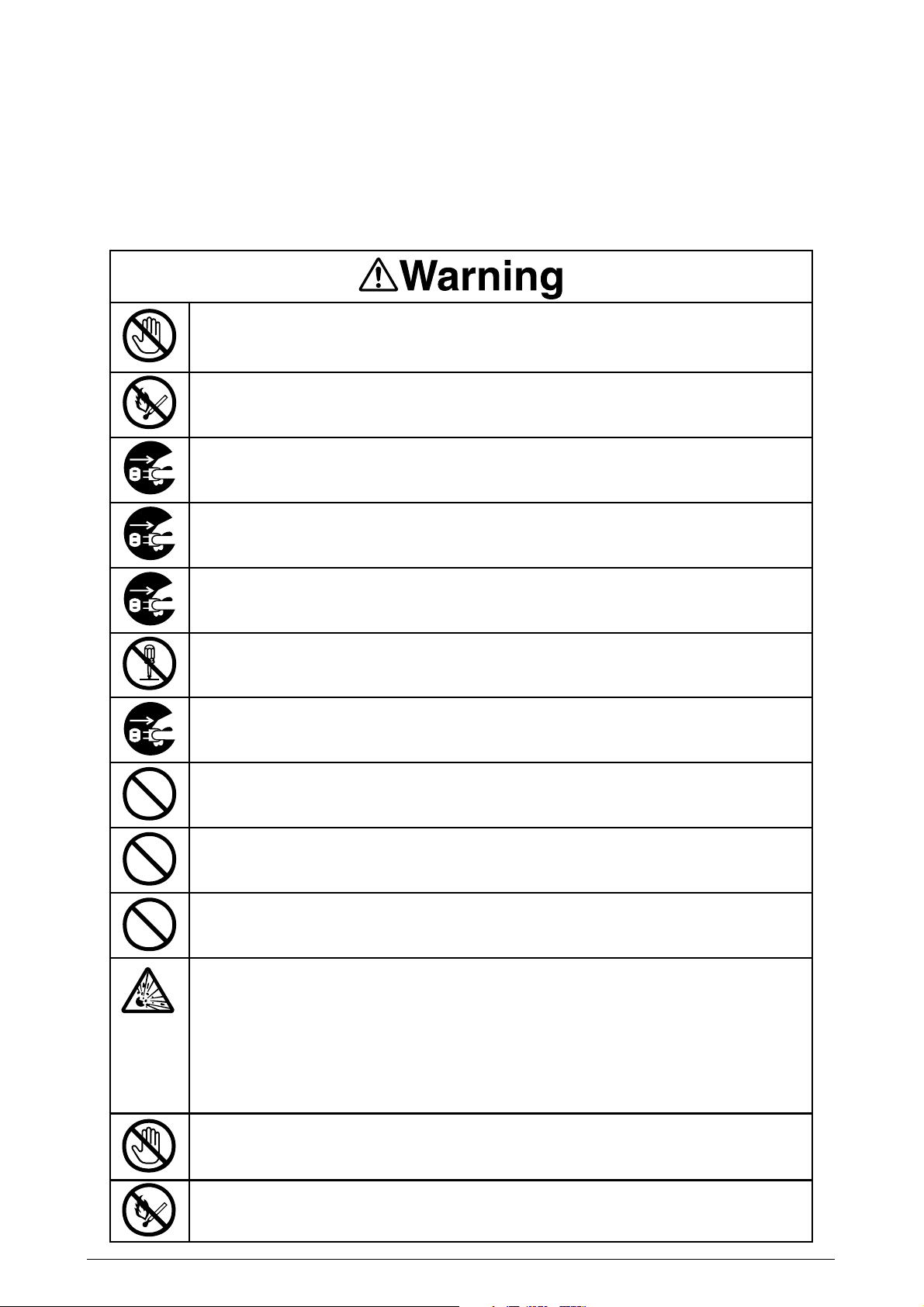
In order to use the product with safety
In order to use the product with safety, make sure to read the user's manual (this manual) before using
the product.
General Caution
Do not touch the safety switch of the internal parts of the printer. Electric shock may
occur due to the occurrence of high pressure. The rotation of the gear may also cause
injury.
Do not use an extremely flammable spray around the printer. Fire may occur because of
parts with high temperature.
Please let our staff in Customer Center know after unplugging mains connector when
the cover gets extremely hot, is smoking, emits questionable odor, or is making strange
noise. Fire may occur.
Please let our staffs in Customer Center know after unplugging mains connector when
liquid such as water goes into the printer. Fire may occur.
Please take a foreign object away after unplugging when you drop foreign objects such
as clips into the printer. That situation may case electric shock, fire, and/or injury.
Do not conduct an operation or an analysis other than specified in user's manual. That
situation may case electric shock, fire, and/or injury.
Please let our staffs in Customer Center know after unplugging mains connector when
the printer has fallen down or damaged. That situation may case electric shock, fire, and
injury.
Do not connect the power cord, the printer cable, or the ground wire other than instructed in user's manual. Fire can be induced if misused.
Do not insert objects at the vent hole. Do not operate the printer with the rear cover
opened. Electric shock, fire, and/or injuries may occur.
Do not place a cup with liquid on the printer. Electric shock, fire, and/or injuries may
occur.
Risk of explosion if battery is replaced by an incorrect type.
Battery of the printer need not to be replaced. Do not touch the battery.
Replace the whole board to replace the CU main board.
In the case of replacing batteries at board repairs, replace with the specified type ones.
stallation of another type batteries may result in explosion.
Caution for used batteries are as follows; do not recharge, force open, heat or dispose
of in fire.
When open the printer cover, do not touch the fuser unit. You may get burned.
In-
Do not throw toner cartridges, or image drum cartridges into fire. You may get burned by
dust explosion.
Rev. 1 4 /
Page 5

Do not go near an ejection area while the power is on and in printing. You may get
injured.
Rev. 1 5 /
Page 6

Table of contents
1. Configuration .................................................................................................10
1.1 System Configuration ................................................................................................... 10
1.2 Printer Composition ...................................................................................................... 11
1.3 Optional Composition ................................................................................................... 12
1.4 Specifications ...............................................................................................................14
2. Descriptions of Operations..........................................................................16
2.1 Main Control PCB ........................................................................................................ 17
2.2 Engine Control PCB (S2V PWB) ................................................................................ 20
2.3 Power Unit .................................................................................................................... 21
2.4 Mechanical process ..................................................................................................... 22
2.4.1 Electrophotographic Processing Mechanism .................................................. 23
2.4.2 Paper Processing Mechanism ......................................................................... 27
2.5 Sensor .......................................................................................................................... 36
2.5.1 Paper-Related Sensor ..................................................................................... 36
2.5.2 Other Sensors ................................................................................................. 37
2.6 Color Drift Correction ................................................................................................... 38
2.7 Image Transfer Control According to Environmental Change (Room Temperature and
Relative Humidity) ........................................................................................................ 38
2.8 Paper Jam Detector ......................................................................................................39
2.9 Cover Open .................................................................................................................. 41
2.10 Toner Low Detection ................................................................................................... 41
2.11 Paper Size Detection ................................................................................................... 44
2.12 Power ON Process ...................................................................................................... 45
2.12.1 Self-Diagnostic Test ......................................................................................... 45
2.13 Color Drift Detection .................................................................................................... 46
2.14 Reading Version of Routine Replacement Units ........................................................ 47
2.15 Life Counter of Replaceable Units .............................................................................. 47
2.16 Toner Usage Level Detection ...................................................................................... 47
3. General Handling Operations ...................................................................... 48
Details undecided. ................................................................................................................... 48
4. Parts Replacement ........................................................................................49
4.1 Precautions When Replacing Parts .............................................................................49
4.2 Parts Layout .................................................................................................................51
4.3 Parts Replacement Method ......................................................................................... 67
4.3.1 Cover-Rear, Cover-Side (R), and Cover-Side (R) Rear ...................................... 68
4.3.2 Cover-Side (L) and Cover Assy-Front ..............................................................69
4.3.3 Stacker Assy-FU.............................................................................................. 70
4.3.4 Cover Assy-OP Panel, Cover-Guard (R), Cover-Guard (Front) and
Cover-Guard (L) .............................................................................................. 71
4.3.5 OP PCB ........................................................................................................... 72
4.3.6 Cover Assy-Top ............................................................................................... 73
4.3.7 FAN-PCB-Assy, CU-Board-Assy and S2V-PU-Board ..................................... 74
4.3.8 Job-Offset-Assy 723 and Basket-Assy ............................................................ 75
4.3.9 Plate Top Assy ................................................................................................. 76
Rev. 1 6 /
Page 7

4.3.10 Eject-Assy ....................................................................................................... 77
4.3.11 Motor-Pulse-Belt and Sensor-Resist-Assy ...................................................... 78
4.3.12 FDR Unit-MPT ..................................................................................................79
4.3.13 FDR Unit-Resist .............................................................................................. 80
4.3.14 Duct Assy ........................................................................................................ 81
4.3.15 HV-Assy ........................................................................................................... 82
4.3.16 Power Unit ......................................................................................................... 83
4.3.17 Low Voltage Power Source Assy and Motor-FAN ........................................... 84
4.3.18 Belt-Assy ......................................................................................................... 85
4.3.19 Fuser Unit-LBT ................................................................................................ 86
4.3.20 Unit-Duplex ...................................................................................................... 87
4.3.21 Paper Feed Roller ........................................................................................... 88
5. Adjustment .....................................................................................................90
5.0 System Maintenance Menu ......................................................................................... 90
5.0.1 ID Check Pattern Print (“TEST PRINT MENU” Item) ...................................... 92
5.1 Maintenance Menu and Its Function .......................................................................... 92
5.1.1 Maintenance Menu .......................................................................................... 92
5.1.2 Engine Maintenance Mode .............................................................................. 94
5.1.2.1 Operation Panel .............................................................................. 94
5.1.2.2 Regular Self-Diagnosis Mode (Level 1) .......................................... 95
5.1.2.2.1 How to Enter Self-Diagnosis Mode (Level 1) ............... 95
5.1.2.2.2 Escape from Self-Diagnosis Mode .............................. 95
5.1.2.3 Switch Scan Test ............................................................................. 96
5.1.2.4 Motor/Clutch Test .......................................................................... 100
5.1.2.5 Test Print ....................................................................................... 104
5.1.2.6 Initialize NVM ................................................................................ 108
5.1.2.7 Consummable Parts Counter Display ........................................... 109
5.1.2.8 Consumable Continual Counter Display ....................................... 109
5.1.2.9 Panel Display Details .....................................................................110
5.1.3 Various Printing Methods with a Stand-Alone Printer Coming with a Controller 115
5.2 Adjustment After Replacing Parts ............................................................................. 116
5.2.1 Precautions when Replacing the Engine Control PCB................................... 116
5.2.2 Precautions Upon EEPROM Replacement ....................................................116
5.2.7 Replacement of the CU Board and Onboard Devices for the 1200-dpi System 119
5.2.8 Precautions When Replacing the KeyChip (1200dpi Model) ......................... 119
5.2.9 Precautions When Replacing the HDD (1200dpi Model) ............................... 119
5.2.10 How to Set Clock (1200dpi Model) ................................................................. 119
5.3 Density Correction ...................................................................................................... 120
6.
Routine Replacement ................................................................................. 121
6.1
6.2
6.3
6.4
Rev. 1 7 /
Routine Replacement of Consumable Parts ............................................................ 121
Cleaning...................................................................................................................... 121
LED Lens Array Cleaning .......................................................................................... 121
Pickup Roller Cleaning .............................................................................................. 121
Page 8

7. Malfunction Repair Procedure ..................................................................122
7.1 Precautions Before Repairs ....................................................................................... 122
7.2 Items to Check Before Remedying Abnormal Image .............................................. 122
7.3 Precautions Before Remedying Abnormal Image .................................................... 122
7.4 Troubleshooting Preparations .................................................................................... 122
7.5 Troubleshooting .......................................................................................................... 122
7.5.1 LCD Message List ......................................................................................... 123
7.5.2 Preparing for Troubleshooting ....................................................................... 133
7.5.3 Troubleshooting With Abnormal Image ......................................................... 146
7.6 Check Fuse ................................................................................................................ 162
8. Connection Diagram ...................................................................................163
8.1 Check Resistance Value............................................................................................ 163
8.2 Diagram of Part Layout of Various PCB .................................................................. 169
9. Interface Specifications ..............................................................................175
9.1 Parallel Interface Specifications ................................................................................ 175
9.1.1 Parallel Interface Overview ........................................................................... 175
9.1.2 Parallel Interface Connector and Cable ........................................................ 175
9.1.3 Parallel Interface Level .................................................................................. 175
9.1.4 Timing Chart .................................................................................................. 180
9.1.5 Parallel Interface Signal ................................................................................ 181
9.2 USB Interface Specifications ..................................................................................... 182
9.2.1 USB Interface Overview ................................................................................ 182
9.2.2 USB Interface Connector and Cable ............................................................. 182
9.2.3 USB Interface Signal ..................................................................................... 182
10. Error message list ......................................................................................183
Rev. 1 8 /
Page 9

Rev. 1 9 /
Page 10
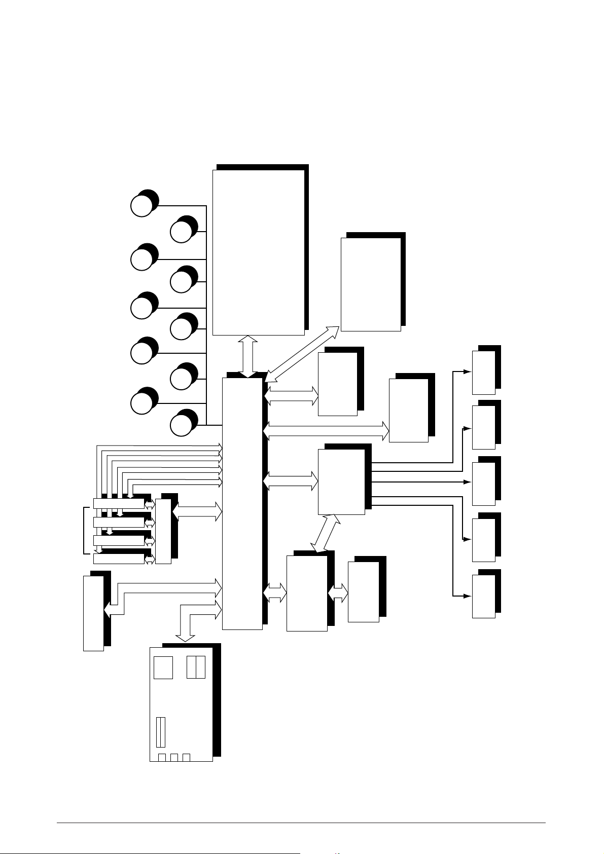
1. CONFIGURATION
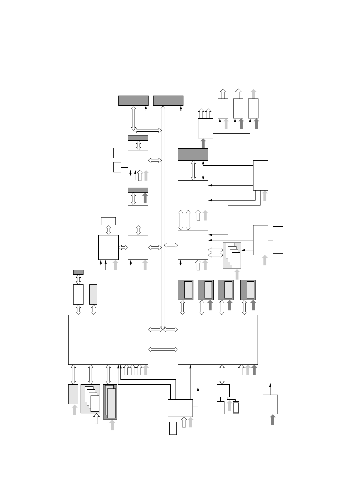
1.1 System Configuration
Figure 1-1 illustrates the System Configuration of this printer.
Motor
Geared
DC motor
M
Hopping
M
MT/
Resist
M
K ID
M
Pulse Motor
Y ID
C ID
Paper Conveyor Sensor
Paper Size Detector
Fuser Temperature Detector
Ambient Temperature/Humidity Detector
Remaining Toner Level Detector
M
<Sensor, Switch and Thermistor>
ID, Belt, Fuser Check
Heavy Paper Sensor
Density Sensor
Color Drift Sensor
<High Performance Sensor>
LED Head
Operation Panel
Belt
Fuser M ID
M M
Connection PCB
IDE
HDD
Job
M
Offset
Paper Tray
2nd/3rd Tray
Large-Volume
Printer Unit
Double-Side
C-ID UnitM-ID UnitY-ID Unit K-ID Unit
Power Unit
High Voltage
Figure 1-1
Engine Controller
Power Unit
Low Voltage
DC FAN
DC FAN
Fuser Unit
Belt Unit
Area
Control
SDRAM DIMM 2
1200dpi PCB (ASP)
USB
Centro
Ethernet
Rev. 1 10 /
Page 11
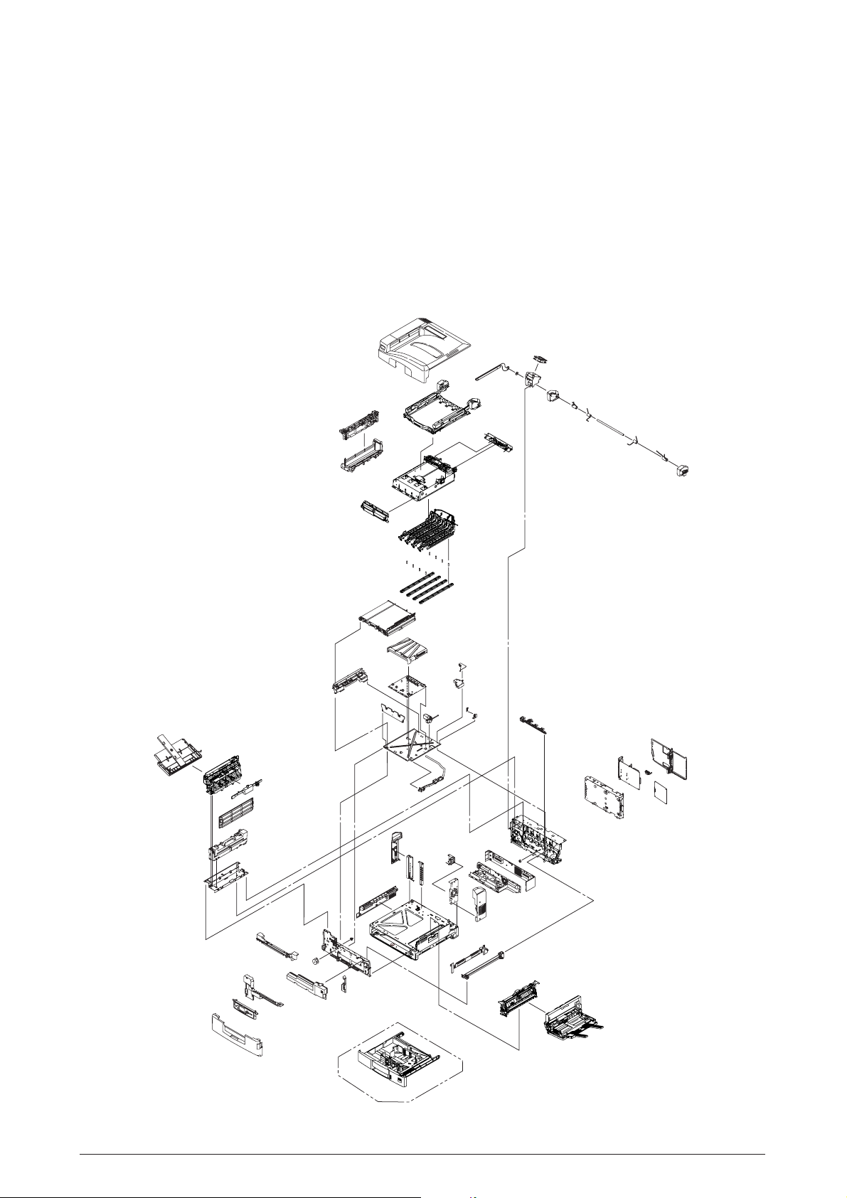
1.2 Printer Composition
The internal part of the printer consists of the following parts.
• Digital Photo Processor
• Paper Travel Path
• Control Unit (CU and PU)
• Operation Panel
• Power Source (High Voltage Area/Low Voltage Area)
Figure 1-2 illustrates the printer composition.
Figure 1-2
Rev. 1 11 /
Page 12
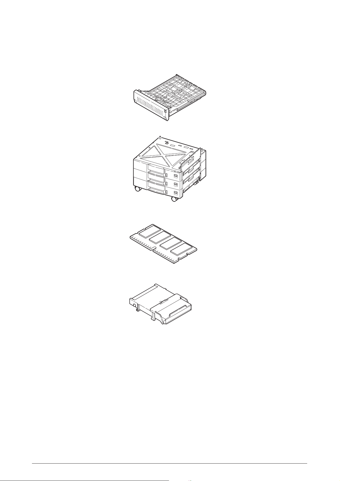
1.3 Composition
This printer comes standard with the following options.
Double-Side Printer Unit
Large-Volume Paper Tray
Additional Memory: 512MB
Internal Harddisk
Rev. 1 12 /
Page 13

Finisher Unit (AR-C36TF)
2/3 Hole Punch Unit (AR-C36HP)
(No Image)
Rev. 1 13 /
Page 14

1.4 Specifications
(1) Dimensions (H × W × D): 462 mm × 640 mm × 615 mm
(2) Weight: 65 kg
(3) Paper
Paper Type: Regular paper and transparency
Paper Size: Post Card, Legal 13”or 14”, Executive, A4, A5, B5, A6,
Continuous Paper Feed: 1st Tray : 55 kg to 172 kg (64 to 203g/m
(4) Print Speed
Color: 36 ppm (OHP: 10 ppm)
Monochrome: 40 ppm (OHP: 15 ppm)
(Recommended: ML OHP01)
A3, A3 Nobi, B4
(However, A6 and Post Card:1stTray and
Front Feeder only)
Front Feeder : 55 kg to 172 kg (64 to 203g/m
2
)
2
)
Post Card, Label, Heavy Paper:
15 ppm
(5) Resolution: 1200 × 600/4bit gray scale
(6) Input Power: 100VAC ±10%
(7) Power Consumption Peak : 1500W
Normal : 750W average (Reference value)
Idle : 200W (Reference value)
Power Save Mode : 55W
(8) Frequency: 50/60Hz ±2Hz
(9) Noise
During Operations: 55dB (when second tray is not attached)
Standby Time: 45 dB
Power Save: 43 dB
(10) Life of Consumables
Toner Cartridge: 7,500 pages (5% Duty)
Large-Volume Toner Cartridge: 15,000 pages (5% Duty) (Y, M, C, K each)
Imaging Drum: 42,000 page (5% Duty, Continuous Printing)
or 30,00 pages (for 3P/J)
(11) Routine Replacement of Consumable Parts
Fuser Unit Assy: 100,000 pages
Transfer Belt: 100,000 pages
Waste Toner Box: 30,000 pages
Rev. 1 14 /
Page 15

(12) Temperature and Relative Humidity
Temperature
Temperature Conditions
Operating
Not Operating
Storage (1 Year Max)
Transport (1 month Max)
Transport (1 month Max)
Relative Humidity
Operating
Not Operating
Temperature
(°F)
50 to 89.6
32 to 109.4
-14 to 109.4
-20 to 122
-20 to 122
Temperature
(°C)
10 to 32
0 to 43
-10 to 43
-29 to 50
-29 to 50
Relative Humidity Conditions
Relative Humidity
(%)
Maximum Web Bulb
Temperature (°C)
20 to 80
10 to 90
26.8
25
Remarks
17 to 27 °C (Temperature
guaranteeing full-color print quality)
Power OFF
Drum and Toner: Yes
Drum: Yes/Toner: No
Drum and Toner: Yes
Remarks
50-70% (Temperature guaranteeing
full-color print quality)
Power OFF
Storage
Transport
10 to 90
10 to 90
35
40
Rev. 1 15 /
Page 16

Rev. 1 16 /
Page 17
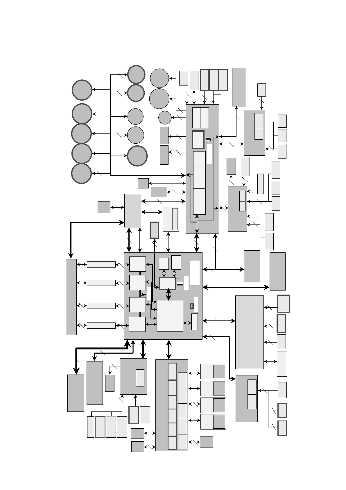
2.1 Main Control PCB
Main Control PCB (ASP-PWB) (1200dpi)
Figure 2-2-1 illustrates the block diagram of the Main Control PCB (ASP PWB).
+1.8V
LT1764EQ
3.3V to 1.8V
+3.3V
1
ENG_CLK
0
ENG_CLK
CLK
VCLK2 SERIAL-
+2.5V
Regulator
5V to 2.5V
LTC3412EFE
+5.0V
nomount
X’tal
30.000
EEPROM
MHz
PCI
PCICLK
Slot
100pin
USB
USB2.0
NET2280
HW_
RESET-N
PCICLK3
Connector
120pinTQFP
+2.5V
+3.3V
Connector
IEEE1284
+5.0V
PCI
Slot
68pin
Regulator
PLLVDD
CVDD
PCICLK2
COREGOOD
PLVDD
MAX1718
5V to CVDD
StepDownCont
+5.0V
I/F
Engine
WDATA0/1/2/3
256pinBGA
Xilinx FPGA
XC2S200E-6FT256C
+3.3V
LM2636
Regulator
5V to 3.3V
+5.0V
Clock Generator
CY27EE16FZEC
14.318MHz
Crystal oscillator
CN
W83783S
FAN Control
S_A[12:0]
8Mbit Flash
Resident 256MByte
+3.3V
Microwire
2kbit EEPROM
S_DQ[63:0]
4
3
2
1
DDR
512Mbit
PCICLK6
SDRAM
+2.5V
LED
XC9572XL
Xilinx FPGA
100pinTQFP
+3.3V
HW_RESET-N
CPU
TM5800
474pinCBGA
C_A[12:0]
C_DQ[63:0]
2
1
SDRAM DIMM
+3.3V
Parallel
74LVX161284
ASIC1
144pinPQFP
PCICLK1
+3.3V, 2.5V, CVDD, PLLVDD
+2.5V
CVDD
PLLVDD
+3.3V
+3.3V
CPU Sideband PCI_AD[31:0]
VIDEO_0/1/2/3
PCICLK5
PCI_CLK_CPU 33MHz
CPU_CLK 66MHz
Clock Gen
X’tal
14.318MHz
LPC BUS
ASIC2
256Kbit
I2CROM
PCI_CLK_SB=33MHz
CLK14MCLK48M
0.75%
Center-spread
+3.3V
+2.5V
+1.8V
+3.3V
544pinPBAG
+1.8V
+3.3V
2Mbit
Boot Flash
+5.0V
XD[7:0]
SA[19:0]
PCI_CLK[6:0]
4MByte
Resident
BRDATA0[31:0]
BRDATA1[31:0]
BRDATA2[31:0]
BRDATA3[31:0]
Primary IDE
CompactFlash
P_DA[2:0]
P_DD[15:0]
M1535+
353pinBGA
SouthBridge
XD[7:0]
RTC
X’tal
32.768MHz
VCLK0/1
4
3
64MB
+5.0V
+3.3V
2
1
8Mbit
PIPELINED
Battery
SRAM
+3.3V
HDD 2.5inch
S_DA[2:0]
S_DD[15:0]
+2.5V
ICLK_VXP
MCLK_VXP
Clock Generator
0/1/2/3
MCLK_SRAM
20GB
Secondary IDE
+5.0V
+3.3V
+5.0V
14.318MHz
Crystal oscillator
CY27EE16FZEC
+3.3V +3.3V
HW_RESET-N
LEUS-T
MAX811
Reset IC
+5.0V
Figure 2-2-1
Rev. 1 17 /
Page 18

The Main Control PCB of the 1200dpi printer consists of a CPU, RAM, HDD, CompactFlash, SouthBridge
LSI, EEPROM, KeyChip, PCI Bus Option and Advanced Interface.
(1) CPU
1GHz Transmeta TM5800 CPU.
(2) RAM
There are 3 types of RAMs. SDRAM DIMM is the only user option RAM. The DDR and
video RAM configuration is fixed and cannot be modified. Only the total memory of the
DDR and SDRAM DIMM is recognized as a usable RAM within the system configuration.
DDR : This is 256MB and 266MHz in speed, and directly soldered on the ASP PCB.
SDRAM DIMM : 128, 256, and 512MB; 133MHz speed, 144p DIMM mounted in DIMM slot.
Video RAM : RAM that is directly soldered on ASP PCB for the video LSI.
(3) HDD/CompactFlash
The 1200-dpi program is stored in a storage medium. Depending on the model, the system
is equipped with HDD or CompactFlash. However, HDD may be added as an option to
a model with CompactFlash. HDD is a mold assembly similar to the one for the 600-dpi
system.
(4) SouthBridge LSI
This is a ALI-make BGA package LSI. It mainly controls the USB I/F, Centro I/F, image
processing LSI, Ethernet board, and MFP extension board via the PCI bus.
(5) Image Processing LSI
This is an EFI-make BGA package LSI. It is mainly for image processing.
(6) EEPROM
This is a 3.3V/256kbit EEPROM with an 8-pin DIP package mounted on the IC socket.
It stores various settings that the control unit manages.
(7) KeyChip
The KeyChip is an 8-pin DIP package mounted on the IC socket. It is purchased from
EFI and stores EFI management information.
(8) PCI Bus
100-pin: An MFP extension board is available as optional equipment.
68-pin: A LAN card is provided as standard equipment.
(9) Advanced Interface
Standard :Centronic Parallel I/F (IEEE-1284)
USB (USB2.0) I/F
Ethernet Board
Additional PCB : MFP Extension Board (PCI BUS Connection)
Rev. 1 18 /
Page 19

Rev. 1 19 /
Page 20
2.2 Engine Control PCB (S2V PWB)
Figure 2-3 illustrates the block diagram of the Engine Control PCB (S2V PWB).
4
Toner
Supply
Motor MC
Fuser
C-ID
M-ID
Y-ID
K-ID
9
Motor
Motor
9
Motor
999
Motor
Toner
44
49
Supply
BELT
Motor
Job
Offset
Toner
Disposal
Motor KY
Motor
Motor
Motor
FAN
FAN
3
Power
UNIT
LV-POWER
11
4
2
BELT
FAN
4
RFID
9
Regist
Tray1
/MPT
PU-
2
Motor
Motor
Geared
1st Regist
Registration
Board
Cover
8
Motor
2
2
Clutch
2
Shutter
3
3
(fuse)
Thermister*4
FUSER UNIT
12
MPT
1st Paper
Size SW
Waste toner
Hole IC
Waste toner
Box Hole IC
Belt
Hole IC
2
5
3
Driver
Tray1/MPT
Motor driver
Regist Motor
SUB
CPU
6
DUPLEX UNIT
13
10
BELT
Motor
Driver
19.66MHz
BOARD-MOTOR-DRIVER (S2M)
KY
TonerSupply
Motor Driver
JobOffset/
Motor Driver
TonerSupplyMC
2nd Regist
Clutch
ENV Sensor
4
2
WR IN2
20
BOARD-
FRONT-SENSOR
(S2S)
70
4
BOARD-
Hum/Temp
END
PAPER
3
1st Paper
Near END
1st
Lifter
(S2C)
Media weight
9
MPT
MPT
Paper End
Hopping
TRAY-SENSOR
3
9
OHP
Sensor
3
3
MPT Paper
END
MPT Home
Position
1st
Cover
IN1
1st
Hopping
C LED HEAD
M LED HEAD
(S2H)
Y LED HEAD
K LED HEAD
44 44
BOARD-LED-HEAD-POWER-RELAY
100
6
10 10 10 10
COCOA
ASIC
COCOA
ASIC
COCOA
ASIC
COCOA
2
(S2R)
SENSOR
Job offset
BOARD-REAR-
6
Cover
Left
ID
FAN
Position
FAN
Fuser
Unit
Contoroller
(X7G)
Solenoid
BOARD-
EXIT
Facedown
OPERATION PANEL
Stacker
Full faceUP
12
Stacker Full
faceDown
Job offset
ASIC
19MHz
13
paper end
Cover
Face UP
(top)
33
32kbit
SRAM
Flash
8Mbit
10
PU-BOARD
CPU
ASIC
MCON
28MHz
EEPROM
(S2V)
9
Short Plug
16
14
24
PCB
C-ID
UNIT
(fuse)
M-ID
Y-ID
K-ID
FAN
UNIT
UNIT
UNIT
ID
(fuse)
(fuse)
(fuse)
(front)
Eraser
PCB
Eraser
PCB
Eraser
PCB
Eraser
Toner
Supply
ID
UpDown
Toner
Supply
Toner-C
Sensor
Toner-M
Sensor
Toner-Y
Sensor
Toner-K
Sensor
3 3 3
33
C-Drum
Phase
(SGG)
M-Drum
Phase
Y-Drum
Phase
BOARD-CARTRIDGE-SENSOR
K-Drum
Phase
(S2J)
(S2J)
(S2J)
(S2J)
14
OPTIONAL
TRAY UNIT
UNIT
HV-POWER
Aligment
Right
Aligment
Left
BOARD-
REGIST-SENSOR
(S2Z)
23 3
2
11
FINISHER/
Disposal
COVER
5
3
3
INVERTER UNIT
Disposal
Toner Full
Hole IC
Toner Box
Upper
(fuse)
BELT UNIT
Density
Sensor
Slack
Paper
Fuser
release
Figure 2-3
Rev. 1 20 /
Page 21

2.3 Power Unit
This is a high voltage power unit consisting of high voltage power source circuit and a low voltage
power unit composed of a power unit consists of an AC filter circuit, low voltage power source circuit
and heater drive circuit.
(1) Low Voltage Power Unit
This circuit generates the following voltage.
Output Voltage
+5V (1)
+5V (2)
+5V (3)
+24V
PU, Logic Circuit Power Source
LED Head
CU
For Monitor Drive
Purpose
(2) High Voltage Power Unit
This circuit generates the following voltage that is more powerful than +24V necessary for
the electrophotographic process, according to the control sequence from the control PCB.
Output
CH
DB
SB
BB
TR
-0.8 to -1.4kV
-100 to -450V/250V
-300 to -700V
Drop from SB Output with Zener
0 to 7kV
Voltage
Purpose
Power to Electrification Roller
Power to Development Roller
Power to Toner Supply Roller
Power to Development Blade
Power to Transfer Roller
Remarks
Rev. 1 21 /
Page 22
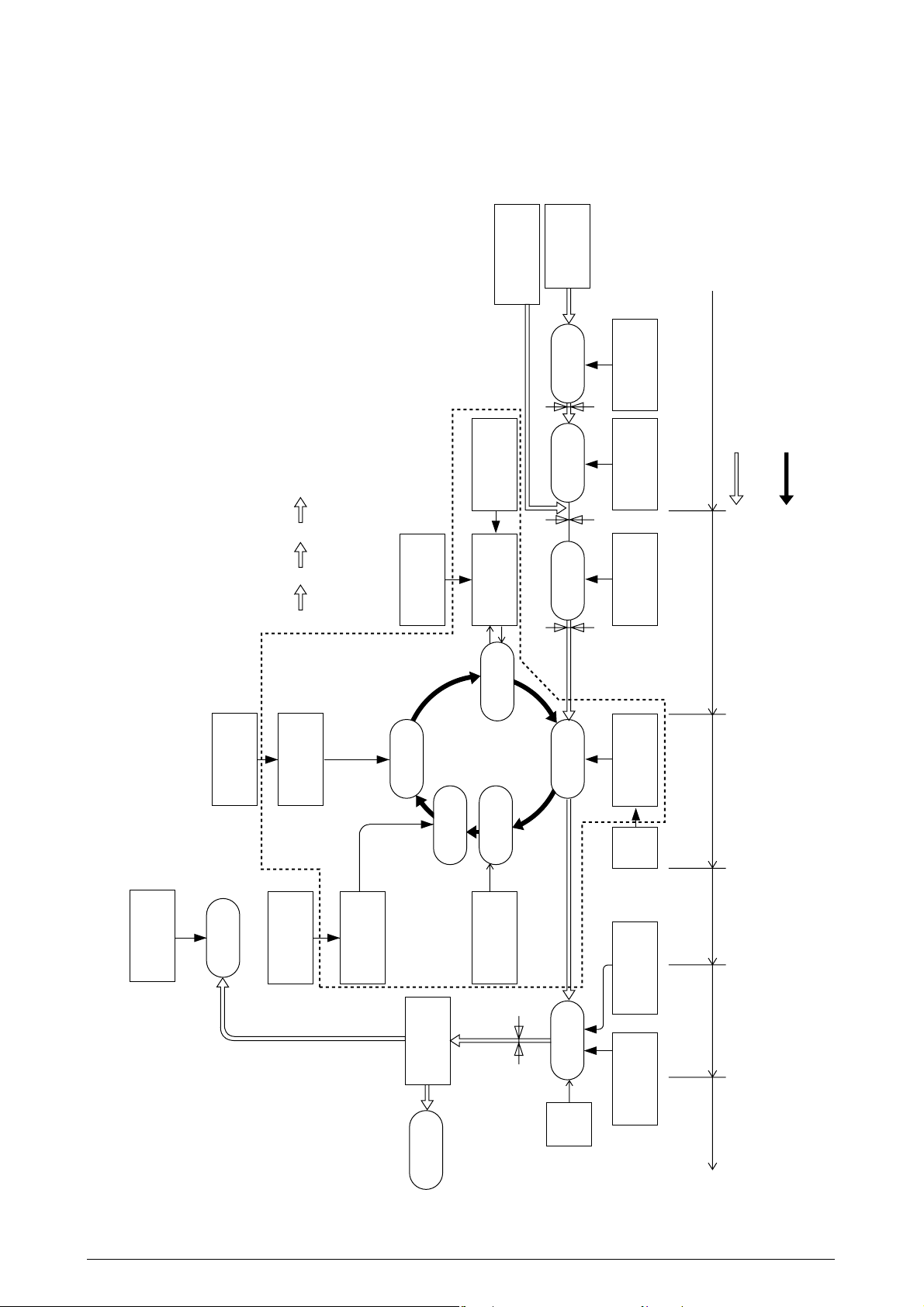
2.4 Mechanical process
Figure 2-4 illustrates the mechanical process of the AR-C360P.
tray
Multi purpose
Paper
cassette
Feeding
(MT, 1ST, 2ND)
Hopping roller
YMC
× 4
K
Control signal
LED head
Power supply
Exposure
Electrification
Toner
Paper feed sensor 1
container
roller
Development
Paper feed sensor 2
Development
Cleaning
regist
Paper
regist
Paper
Transfer
Regist roller 1Regist roller 2
Light sensor
Transfer roller
Power
supply
A motion of a paper
OPC drum rotation
roller
Discharge
Discharge
(Face down)
Power supply
roller
Electrification
Cleaning blade
Backup roller
selection
Paper path
Fixing
Heat roller
roller
Discharge
Discharge Fixing Cleaning Transfer Paper conveyance Paper advance
(Face up)
Discharge
Discharge sensor
Figure 2-4
Rev. 1 22 /
Page 23

2.4.1 Electrophotographic Processing Mechanism
(1) Electrophotographic process
The overview of the electrophotographic process is described below.
1 Electrification
DC power is applied to the CH roller to evenly negatively electrify the surface of the
OPC drum.
2 Exposure
The LED head irradiates light on the surface of the OPC drum that is charged with
a negative electrical load. The negative electrical load attenuates according to the
intensity of light, for the irradiation area of the OPC drum surface. Further, the
electrostatic latent image is created on the OPC drum surface according to the
electrical potential.
3 Development
The negatively charged toner comes in contact with the OPC drum to fuse the
electrostatic latent image by electrostatic force, to create a significant image on the
surface of the OPC drum.
4 Transfer
Paper is pressed against the surface of the OPC drum, then conveyed by the transfer
roller from behind. The toner and positive electrical load of a reverse electrode is
applied, then the toner image is transferred to the paper.
5 Cleaning
The cleaning blade removes residual toner on the OPC drum after the toner is
transferred to the paper.
6 Fuser
Heat and pressure is applied to the toner image on the paper to fuse the image on
the paper.
Rev. 1 23 /
Page 24
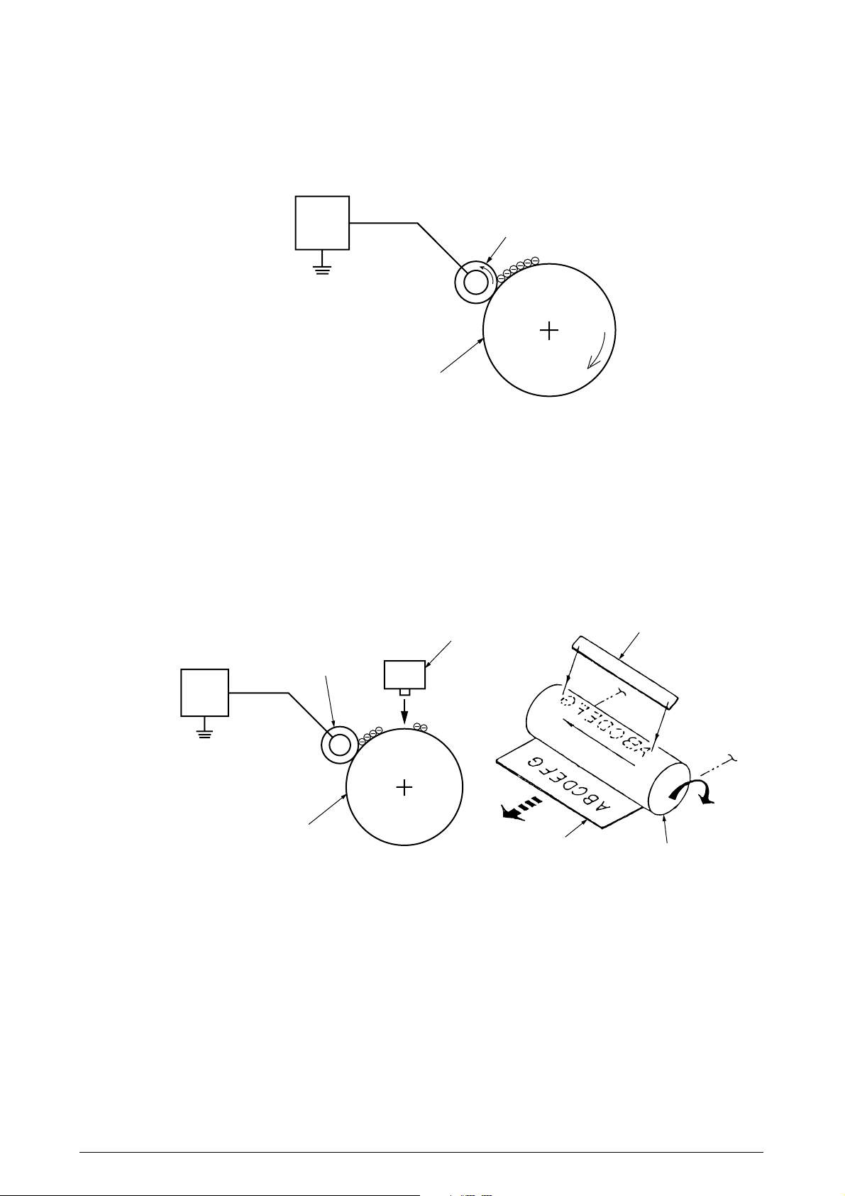
(2) Electrification
A negative DC power is applied to the electrification roller to evenly negatively electrify
the surface of the OPC drum.
Power
supply
unit
Electrification roller
OPC drum
(3) Exposure
The LED head irradiates light on the surface of the OPC drum that is charged with a
negative electrical load. The negative electrical load attenuates according to the intensity
of light, for the irradiation area of the OPC drum surface. Further, the electrostatic latent
image is created on the OPC drum surface according to the electrical potential.
Power
supply
unit
Electrification roller
OPC drum
LED head
Paper
LED head
OPC drum
Rev. 1 24 /
Page 25
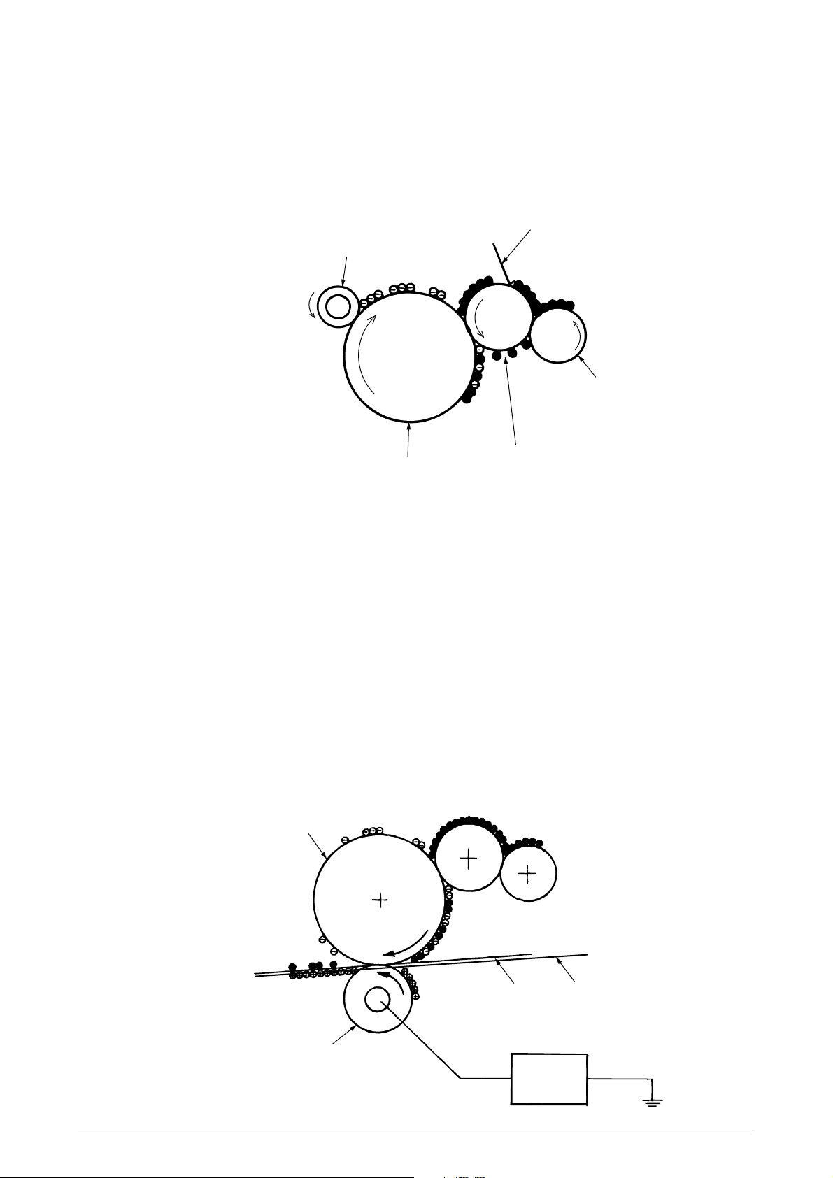
(4) Development
The negatively charged toner comes in contact with the OPC drum to fuse the electrostatic
latent image by electrostatic force, to create a significant image on the surface of the OPC
drum.
1 The sponge roller precipitates toner on the development roller. The toner is then
negatively electrified.
Electrification roller
Development blade
Sponge roller
OPC drum
Development roller
2 The development blade removes excess toner from the development roller, then a
thin toner layer is created on the development roller.
3 The toner is sucked into the electrostatic latent image where the OPC drum and
development roller comes in contact.
(5) Transfer
The transfer roller is made of a conductive sponge. Paper is pressed against the OPC
drum surface, then the paper and OPC drum surface is adhered.
Paper is pressed against the surface of the OPC drum, then conveyed by the transfer roller
from behind. The toner and positive electrical load (that is reverse with the toner) is applied,
then the toner image is transferred to the paper.
When the power source applies powerful positive power on the transfer roller, the positive
electrical load induced by the transfer roller is transferred to the paper surface at the
contact point between the transfer roller and paper. The negative electrical load toner is
then sucked from the OPC drum surface on to the paper surface.
OPC drum
Paper
Transfer roller
Rev. 1 25 /
Conveyance belt
Power
supply
unit
Page 26
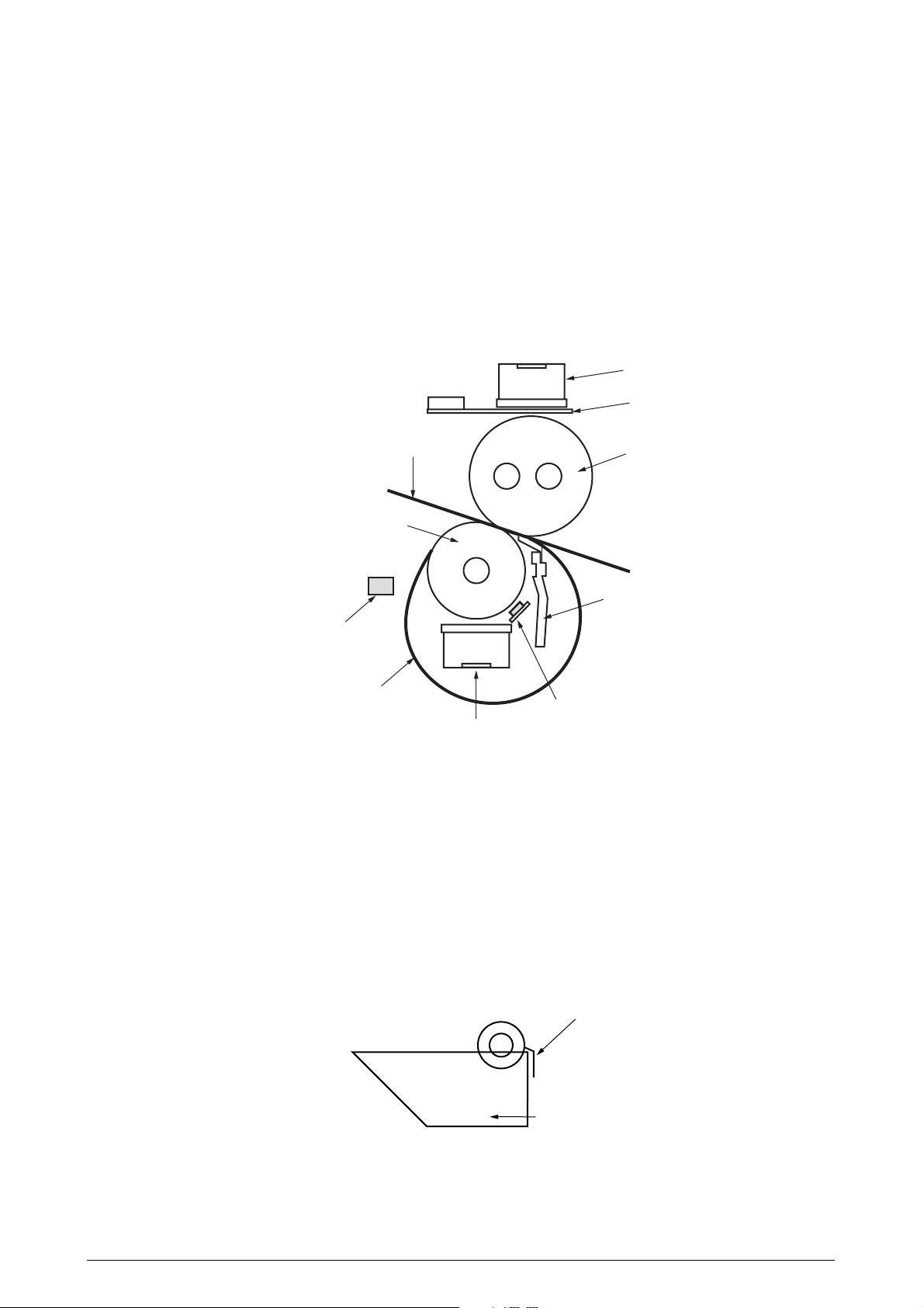
(6) Fuser
The toner image transferred on the paper is fused on the paper by heat and pressure when
the paper passes through the heat roller and backup roller.
The Teflon coated heat roller is heated by a 800W or 350W internal halogen lamp, and
backup roller is heated by a 50W internal halogen lamp. The fuser temperature is controlled
according to the sum of the temperature that is not contacted with the thermistor ground
against the heat roller surface and the temperature that is detected with the thermistor
ground on the backup roller surface. There is also a thermostat for safety purposes. When
the heat roller temperature rises above a certain temperature, the thermostat opens and
shuts down the power supplied to the heater. The backup roller unit is pressed against the
heater with a press spring on both sides.
Thermostat
Thermistor
Paper
Backup roller
Backup roller unit
Fuser belt
Thermistor
Thermostat
Heat roller
Pat
(7) Cleaning
The cleaning blade scrapes off residual toner on the OPC drum after the toner is transferred to the paper, then the disposal toner of the disposal toner box is collected at the
rear.
(8) Cleaning
The cleaning blade scrapes off residual toner on the transfer belt then collects is in the
disposal toner box of the transfer belt unit.
Cleaning braid
Disposal Toner Box
Rev. 1 26 /
Page 27
2.4.2 Paper Processing Mechanism
Figure 2-5 illustrates how the paper transfers through the AR-C360P.
Face down stacker
Discharge roller
Discharge roller
Backup roller
Fuser assembly
Heat roller
Cassette 1
Cassette 2
Cassette 3
Low-pressure
power supply
Belt unit
Head x4
High-pressure
power supply
Unit x4
Regist roller Assy (B)
Hopping roller
Multipurpose tray
Cleaning blade
Regist roller Assy (A)
Transfer roller
Feed roller
Cassette 4
Cassette 5
Figure 2-5 Paper Path
Rev. 1 27 /
Page 28

(1) Paper Supplied from the 1st Tray
1. Paper proceeds when the paper supply motor turns (CCW) and the paper supply
clutch is connected, until the IN1 sensor turns ON.
2. When the IN1 sensor is turned ON, a certain volume of paper is further transported
until it is against the 1st resist roller. (this corrects paper skew)
3. The paper is transported to the transport belt when the electromagnetic clutch which
delivers power that the register strike motor is turning (CW) and the thrust reliance
of a paper is completed to the 1st register strike roller is connected.
2nd regist roller
Write sensor
IN2 sensor
Middle transport roller
The clutch of
electromagnetism
Pickup roller
Feed motor
Feed roller
Paper
The clutch of
electromagnetism
Feed sensor
Retard roller
Figure 2-6
1st regist roller
IN1 sensor
Regist motor
Rev. 1 28 /
Page 29
(2) Paper Supplied from the Option Tray
1. Paper proceeds when the paper supply motor turns (CCW) and the paper supply
clutch is connected, until the IN sensor of the top tray to supply the paper, turns ON.
2. When the IN sensor is turned ON, a certain volume of paper is further transported
against the regist roller. (this corrects paper skew)
3. The paper is conveyed to the AR-C360P when the electromagnetic clutch which delivers
power that the register strike motor is turning (CW) and the thrust reliance of a paper
is completed to the 1st register strike roller is connected.
electromagnetism
Regist motor
The clutch of
electromagnetism
The clutch of
1st Regist roller
IN1 sensor
Regist roller
Upper tray
Option paper tray
IN sensor
Pickup roller
Feed motor
Feed roller
Retard roller
Feed sensor
Regist motor
Figure 2-7
Rev. 1 29 /
Page 30

(3) Paper Supplied from MPT
1. In the usual case, sheet receiving is depressed by the arm for rise and fall at a home
position.
2. When a regist motor rotates in the direction of (b), the arm for rise and fall drives
and sheet receiving is rotated. The paper on sheet receiving goes up to the position
where a lift rise sensor is turned on, and feeding is attained because the arm for rise
and fall goes up.
3. The hopping motor is shared with the tray and MPT feeding uses the inversion of
tray feeding.
If a hopping motor reverse-rotates, a pickup roller and a feed roller will drive and a
paper will be sent out.
4. After an entrance sensor (2) is turned on by the paper tip, a paper is sent by
specification length. A paper will stop, if the tip reaches the 2nd register strike roller
Assy.
5. A regist motor rotates in the direction of (a) simultaneously, and a paper is conveyed
with the 2nd regist roller Assy. A hopping motor is rotated until a paper arrives at
the position of the image drum cartridge (black).
6. A hopping motor is rebooted, in order to make paper feed to the following paper, when
an after the end escapes from the hopping sensor.
7. When operation of 4 to 6 is repeated and a lift rise sensor turns off, a regist motor
is rotated in the direction of (b), and the arm for rise and fall is driven, and it goes
up until a lift rise sensor turns on the paper on sheet receipt.
8. After the completion of paper sending operation, when a lift rise sensor detects off,
a regist motor is rotated in the direction of (b), and sheet receiving is returned to a
home position by dropping the arm for rise and fall.
Rev. 1 30 /
Page 31

Feed roller
Entrance sensor (2)
Write sensor
2nd Regist roller Assy (B)
The clutch gear of
electromagnetism (2)
Hopping sensor
Retard roller
Pickup roller
Lift up sensor
Paper existence sensor
Paper
Paper existence sensor
Middle transport roller
Hopping motor drive
a
Regist motor drive
b
Figure 2-8
Rev. 1 31 /
Page 32

(4) Conveyor Belt
1. The conveyor belt motor drives the conveyor belt when turning in the direction of the
arrow (a). The belt unit consists of one conveyor roller that is directly under the drum
for each color, with the conveyor belt in between the drum.
When a specified voltage is applied, the conveyor belt and conveyor roller transfers
the toner image on the drum for each color, then feeds the paper on the conveyor
belt to the fuser unit.
Drum
Conveyor belt
KY MC
Transfer roller
Transfer belt motor
Figure 2-9
Rev. 1 32 /
Page 33

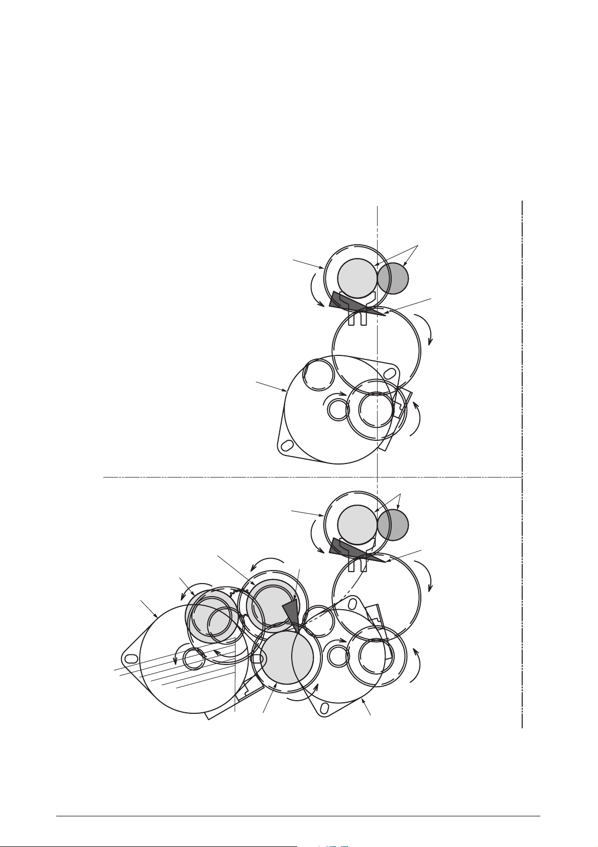
(5) ID Unit Up/Down Operations
1. The C-ID motor drives the ID unit up and down.
2. Figure 2-10-a indicates ID unit operations during color printing. When the C-ID motor
rotates (CCW), the lift uplink slides to the left, and as indicated in Figure 2-10-a, each
ID unit moves DOWN. The printer is now ready for color printing.
3. Figure 2-10-b indicates the ID unit operations during monochrome printing. When the
C-ID motor rotates (CW), the lift uplink slides to the right, and as indicated in Figure
2-10-b, all units other than the K-ID moves UP. The printer is now ready for blackand-white printing.
ID Unit Operations During Color Printing
C-ID Unit down
M-ID Unit down
Y-ID Unit down
K-ID Unit down
Lift uplink
C-ID Unit M-ID Unit
C-ID Motor
(CCW)
Figure 2-10-a
ID Unit Operations During Monochrome Printing
C-ID Unit lift up
M-ID Unit lift up
Y-ID Unit lift up
K-ID Unit down
C-ID Unit M-ID Unit
Y-ID Unit
Y-ID Unit
K-ID Unit
K-ID Unit
Lift uplink
C-ID Motor
(CW)
Figure 2-10-b
Rev. 1 33 /
Page 34

(6) Fuser Unit and Paper Output
1. The fuser unit and discharge roller is driven by a single DC motor. The heater roller
turns when the fuser motor turns in the direction of the arrow (a). This roller fuses
the toner image on the paper with heat and pressure.
2. At the same time, the four discharge rollers are activated to discharge paper.
3. The discharge path to the face-up or face-down stacker is automatically switched by
the paper separator solenoid.
Discharge roller
Face-down stacker
Face-up stacker
Fuser unit
Heat roller
Paper separator
a
Fuser motor
Figure 2-11
Rev. 1 34 /
Page 35

(7) Double-Side Printer Unit
1. When the double-side Printer Unit receives double-side print instructions, the separator is opened by the solenoid after one side of the paper fed from the tray is
completely printed, then the path is switched to the double-side printer unit.
At this time, roller (1) turns in the direction of arrow (a), therefore, the paper is
retracted to the undersurface of a double-side printer unit.
2. Further, when the tip of the paper passes through the double-side printer entrance
sensor after a certain period of time, the roller starts a reverse rotation. Roller (1)
turns in the direction of arrow (b), then sends the paper inside the double-side printer
unit. After that, it passes through roller (2), (3), (4) and (5), prints the other side of
the paper, then discharges the paper, and re-feeds it back to the unit.
Separator
Solenoid
Double-sided
entrance sensor
Roller (1)
a
b
Motor A
Motor B
Roller (2)
Roller (3)
Figure 2-12
Roller (4)
Roller (5)
Rev. 1 35 /
Page 36

2.5 Sensor
2.5.1 Paper-Related Sensor
Stacker Full FD sensor
Stacker Full
FU sensor
Dup-in sensor
Dup-in2 sensor
Job-off sensor
Drive roller
Exit sensor
Looseness sensor
Sensor
Entrance MT Sensor
Entrance Cassette Sensor
Entrance Belt Sensor
Paper Discharge Sensor
Double-Side Print
Entrance Sensor
Double-Side Print Rear
Sensor
Double-Side Print Front
Sensor
Stack Full Sensor
Face-Down Paper
Discharge Sensor
Face-Down Route Sensor
Conveyance Sensor
C drum K drumY drumM drum
Drive roller
WR sensor
MPT home sensor
Density / color gap sensor
Dup R sensor
Conveyor belt
Dup F sensor
Function
This detects the top of the paper entering and
then determines the timing to switch from the
hopping to the conveyor.
This detects the tip of the paper transferred,
then determines the length of the paper
according to the time it takes the tips of the
paper to reach the sensor.
This detects the tip and end of the paper, then
determines paper discharge.
This determines the tip of the paper entering
the double-side printer unit, then determines
the times it takes for the inverse roller to
inverse from CCW to CW.
This detects the tip of the paper after inversion
by the double-side printer unit.
After inversion by the double-side printer unit,
the end and tip of the paper is detected and
then paper discharge is determined.
This detects paper-full in the face-down
stacker.
This detects paper conveyance to the paper
discharge roller, then determines the timing to
offset job operations.
When the paper jams, this detects the paper
jam in the face-down conveyance rotor.
This detects the paper conveyed from the
option tray.
IN2 sensor
MPT Hopping sensor
Paper Hopping sensor
State of Sensor
ON
: Paper Available
OFF
: Paper Unavailable
ON
: Paper Available
OFF
: Paper Unavailable
ON
: Paper Available
OFF
: Paper Unavailable
ON
: Paper Available
OFF
: Paper Unavailable
ON
: Paper Available
OFF
: Paper Unavailable
ON
: Paper Available
OFF
: Paper Unavailable
ON
: Stack Full
OFF
: Stack Empty
ON
: Paper Available
OFF
: Paper Unavailable
ON
: Paper Available
OFF
: Paper Unavailable
ON
: Paper Available
OFF
: Paper Unavailable
MPT PE sensor
IN1 sensor
Rev. 1 36 /
Page 37

2.5.2 Other Sensors
1 Paper Empty Sensor
This sensor checks whether the paper cassette is empty or not.
2 Paper Near-End Sensor
This sensor checks whether the paper cassette will be empty soon or not.
3 MBF Paper Empty Sensor
This sensor checks whether there is paper in the front feeder.
4 MBF Hopping Switch
This micro-switch checks whether the front feeder table is in the UP position or DOWN
position.
5 Stack-Full Sensor
This sensor checks whether the stacker is full or not.
6 Paper Size Switch
This sensor detects the size of the paper in the paper cassette.
7 EP UP/DOWN Sensor (one sensor each for Y, M, C, K)
This sensor checks whether the I/D unit is in the UP position or DOWN position.
8 Toner K, Y, M and C Sensor
This sensor checks the toner residual quantity in an image drum, when a sensor lever
measures a time interval to open periodically.
9 RFID Sensor
The radio communications of this sensor are carried out to IC tip built in the toner cartridge,
and it checks the existence of a toner cartridge, and the toner residual quantity in a toner
cartridge.
0 Thermal Sensor
Refer to 2.7 “Image Transfer Control Due to Environmental Change”.
A Humidity Sensor
Refer to 2.7 “Image Transfer Control Due to Environmental Change”.
B Transparency Sensor
This sensor detects whether there is a transparency or not.
C Positioning Sensor
This sensor reads the printed position pattern on the left and right ends of the transfer
belt when color drift is corrected. (Refer to Section 2.13)
D Density Sensor
This sensor measures the pattern density to measure the density printed on the conveyor
belt.
E Media Thickness Sensor
This sensor detects the thickness of the media.
F Disposal Toner Sensor
This sensor checks whether the disposal toner in the disposal toner box is full or not.
G Looseness Sensor
This sensor detects looseness in paper transport and adjusts the speed.
Rev. 1 37 /
Page 38

2.6 Color Drift Correction
The AR-C360P comes with several ID units and LED heads, therefore, causes color drift. This mechanical
color drift can automatically be corrected with the following procedures.
(1) Automatically Corrected Color Drift
1 X Axis Color Drift (position off-alignment due to LED head)
2 Skew Color Drift (position off-alignment due to LED head)
3 Y Axis Color Drift (I/D unit and position off-alignment due to LED head)
(2) Correction Method
The color drift detection pattern set is printed on the belt. This is then read by the reflection
sensor to detect the color drift value of each color and therefore, determine the correction
level. The modification takes place by comparing the each colors’ (Cyan, Magenta and
Yellow) write timing with black, according to the correction value.
2.7 Image Transfer Control According to Environmental Change (Room Tempera-
ture and Relative Humidity)
The AR-C360P measures the room temperature with the room temperature sensor and measures the
relative humidity with the humidity sensor. It further computes the optimal transfer voltage under the
environmental conditions (temperature and RH) measured. Then printing is controlled in real-time at
this optimal voltage.
Environmental Detection Table
Sensor reading value
5† <10
10† <15
15† <20
Tempe-
rature
20† <25
(°C)
25† <30
30† <35
35† <40
Sensor reading value
5† <10
10† <15
15† <20
Tempe-
rature
20† <25
(°C)
25† <30
30† <35
35† <40
<5
40†
<5
40†
Sensor reading value
Register value
<59(H)
16B(H)† <19E(H)
19E(H)† <1D1(H)
1D1(H)† <204(H)
204(H)† <236(H)
236(H)† <265(H)
265(H)† <290(H)
290(H)† <2B9(H)
2B9(H)†
Sensor reading value
Register value
<59(H)
16B(H)† <19E(H)
19E(H)† <1D1(H)
1D1(H)† <204(H)
204(H)† <236(H)
236(H)† <265(H)
265(H)† <290(H)
290(H)† <2B9(H)
2B9(H)†
<15
<1E(H)
<15
<1E(H)
N/L1 N/L1 N/L2 N/N
N/L1
H/L
8
8
8
8
7
7
7
6
6
15† <25
1E(H)† <33(H)
8
8
8
7
7
6
6
6
5
15† <25
1E(H)† <33(H)
L/L
H/L
25† <35
33(H)† <47(H)
8
8
7
7
6
6
5
4
4
25† <35
33(H)† <47(H)
N/L2 N/N
35† <45
47(H)† <5C(H)
35† <45
47(H)† <5C(H)
7
7
7
6
5
4
4
2
2
Humidity (%)
45† <55
5C(H)† <70(H)
7
7
6
5
4
4
2
1
1
Humidity (%)
45† <55
5C(H)† <70(H)
H/H
55† <65
70(H)† <85(H)
7
6
5
4
4
3
1
H/H H/H
1
1
55† <65
70(H)† <85(H)
H/H H/H
65† <75
85(H)† <99(H)
7
6
5
4
3
H/H H/H
1
1
1
1
65† <75
85(H)† <99(H)
H/H H/H
75† <85
99(H)† <AE(H)
6
5
4
3
3
1
1
1
1
75† <85
99(H)† <AE(H)
85 †
AE(H)†
6
5
4
3
2
1
1
1
1
85 †
AE(H)†
Rev. 1 38 /
Page 39

2.8 Paper Jam Detector
The AR-C360P detects paper jam during printing after turning on the power source. If there is any paper
jam detected, the printing process is immediately canceled. In this case, open the cover, remove the
paper that is jammed, and close the cover to resume printing.
Error Code Displayed on LCD
400,401
372
Paper Size Error
Mis-feeding in Double-Side
Print Conveyance Assy
390
1-391
2-392
MT mis-feed.
Cassette 1, 2, 3, 4 or 5 mid-
feed.
3-393
4-394
5-395
370
Paper jam when printing on
the other side with Double-
Side Print.
383
Paper jam at the entrance
of the Double-Side Printer
Unit.
371
Paper jam at the input of the
Double-Side Printer Unit.
382
381
380
490
1-491
2-492
Paper discharge jam.
Paper conveyance jam
Paper output jam.
MT out of paper.
Cassette 1, 2, 3, 4 or 5 out
of paper
3-493
4-494
5-495
Error
State
After the Entrance Cassette Sensor turns ON, it
won t turn OFF for a certain period of time. It detects
several different types of paper sizes.
Failure to feed paper from the Double-Side Print
Conveyance Assy.
Paper feed from the MT failed. (If, after Hopping, the
Entrance MT Sensor does not turn ON within a
certain period of time)
Paper supply failed from Cassette 1, 2, 3, 4 and 5.
(If, after Hopping, the Entrance Cassette Sensor
does not turn ON within a certain period of time)
The double-side printer rear sensor does not turn
ON when printing the other side with the double-side
printer unit.
The double-side printer IN sensor does not turn ON
when supplying paper to the double-side printer unit.
The double-side printer front sensor does not turn
ON while the double-side printer unit is operating.
The paper discharge sensor senses the tip of the
paper but does not sense the end of the paper after
that within a certain period of time. The paper
discharge sensor turns ON, but does not turn OFF
after that.
The paper is conveyed on the belt, however, the
paper discharge sensor does not turn ON.
After hopping is completed, the paper does not
reach the entrance belt sensor or the MT sensor.
If printing is started when the MT is out of paper.
Cassette 1, 2, 3, 4 or 5 out of paper
Entrance belt sensor
Double-side print
entrance sensor
Double-side print rear sense
370
382
Discharge
Discharge sensor
Double-side
383
print entry
Double-side print
front sensor
Double-side print rear sense
381
Paper
conveyor
Double-side print input
371
Entrance MT sensor
Cassette 1
Cassette 2
Cassette 3
Cassette 4
Cassette 5
380
Paper feed
390
Entrance cassette sensor
372
391
392
393
394
395
Multipurpose tray part
(MT)
Mis-feed in MT
Mis-feed in double-sided printing
Mis-feed in a cassette 1
Mis-feed in a cassette 2
Mis-feed in a cassette 3
Mis-feed in a cassette 4
Mis-feed in a cassette 5
Rev. 1 39/
Page 40

Rev. 1 40 /
Page 41

2.10 Toner Low Detection
• Structure
This device consists of a constant speed rotating agitation gear and agitation bar.
Projection Agitation barAgitation gear
• Detection
The minimum height length of stay (OFF time) of a target board which attached the toner
low level state in the end of a churning bar is measured and detected by the sensor.
OFF time (minimum height) ON time (maximum height)
Sensor
Agitation bar
Target board
The light which emitted light by the
sensor reflects with a target board, and
received light by the sensor. Therefore,
the minimum height length of stay is
detectable.
The light which emitted light by the
sensor does not reflect with a target
board, and does not received light by
the sensor.
Rev. 1 41 /
Page 42

Toner High level State
• The agitation bar interlocks and turns with the
agitation gear.
• Since there is a toner even if a agitation bar
reaches the maximum height, the other side
of the bar is still inside the toner. Therefore,
the agitation bar turns by the force of the
agitation gear.
Toner Low Level State
Agitation bar
Target board
• When the agitation bar reaches the maximum height, the agitation bar falls in the
minimum height by prudence since there is
no resistance by the toner. At this time, the
minimum height length of stay of a target
board becomes long. This time is measured
and a toner low level state is detected.
Toner Supply Operation
• When continuation 3 cycle detection of the
toner low level state is carried out, a toner
supply roller and a toner cartridge agitation
spring will rotate, and the toner of a toner
cartridge will be supplied to the inside of an
image drum cartridge. Then, when one cycle
of toner high level is detected, toner supply
agitator and a toner cartridge agitation spring
will stop, and toner supply will stop.
Toner cartridge
agitation spring
Toner supply board
Agitation bar
Target board
Rotation direction of
toner supply agitator
Rev. 1 42 /
Page 43

Toner High Level State (at 37ppm*1)
ON
TNRSNS t1<0.85
OFF
t1
T=2.3
Toner Low Level State (at 37ppm
ON
TNRSNS
OFF
• After a toner supply start, when a toner low sate is detected 20 consecutive times, it is
recognized as the toner being low.
(After recognizing toner low, then toner low is displayed after printing an equivalent of 5%
of 200 A4 sheets.)
The toner in a toner cartridge is lost.
• If a toner full state is detected 10 consecutive times, the toner low state is canceled.
• If the toner sensor does not change over 3 cycles (2.3 sec. X 3), then the toner sensor
alarm is activated.
• The toner sensor does not detect anything when the drum motor is stopped.
*1
A 37ppm printout is at the warming up stage. T and t1 fluctuates in proportion to the
printing speed.
*1
)
t1
t1>0.85
T=2.3
Rev. 1 43 /
Page 44

2.11 Paper Size Detection
A cam is interlocked with the paper guide of the paper cassette, then four tab-pieces via this cam drives
the system according to the paper guide setting position.
When the paper cassette is attached to the printer, the micro-switch detects the state of the tab-piece
and then recognizes the size of the paper.
Cassette NONE
A3 Nobi
Tabloid
A3
B4
Legal 14"
Legal 13"
A4 Portrait
Letter Portrait
Executive
B5 Portrait
Letter Landscape
A4 Landscape
A5
B5 Landscape
A6
PSZSW1
0
0
1
1
0
0
0
1
1
1
1
1
0
0
1
0
PSZSW2
0
0
0
0
0
1
1
1
1
1
1
0
0
1
0
1
PSZSW3
0
1
1
0
0
0
0
1
1
0
0
1
1
1
0
1
PSZSW4
0
1
1
1
1
1
0
0
1
1
0
0
0
0
0
1
Rev. 1 44 /
Page 45

2.12 Power ON Process
2.12.1 Self-Diagnostic Test
(1) Initial Test
When the power is turned On, the following check automatically takes place.
(a) ROM Check
(b) RAM Check
(c) EEPROM Check
(d) Flash ROM Check
(e) Mechanical Check
(f ) Option Unit Check
(2) ROM Check
The ROM is checked by calculating the HASH value.
(3) RAM Check
(a) The type of RAM is checked for its specifications. Any RAM that falls out of the
specifications will result in an Error.
(b) The RAM in each slot is checked by read-after-write.
(4) EEPROM Check
The specific data stored in the fixed address of the EEPROM is checked.
(5) Flash ROM Check
The flash ROM format is checked. If it is unformatted, then read-after-write check takes
place and the flash ROM is formatted.
(6) Option Unit Check
Before entering the run mode, the unit is checked for the presence of an optional units
(HDD, NIC, Option Tray, Double-Side Printer Unit, Finisher, etc.).
Rev. 1 45 /
Page 46

2.13 Mis-Registration Detection
The Z71-PCB reflective optical sensor detects color drift. There is one each on the left and right side
in front of the cleaning blade behind the belt unit. A color drift detection pattern is printed on both ends
of the left and right side of the belt. Then the reflective optical sensor reads this detection pattern to
measure the drift level based on black as a standard. The correction value is then determined based
on this measurement. Then the main scanning, sub-scanning, and skewed color drift correction automatically takes place.
This detection takes place when the power is turned ON, cover is closed, the printer is left unused
for 2 hours or longer, and every time after printing 400 sheets.
LED head
CMYK
ID
CMYK
Transfer belt
The belt run direction
Color drift sensor L/R
Transfer belt
Color drift sensor R
The belt run direction
Color drift sensor L
(Figure seen from the bottom)
Cleaning blade
Cleaning blade
Rev. 1 46 /
Page 47

2.14 Reading Version of Routine Replacement Units
This determines whether the parts are new or old according to the I/D of the consumable parts that
are routinely replaced, the fuser unit, and the state of the fuse in the belt unit (good/dead). If the fuse
is in a conductive state, then it is considered a new unit. A NEW or OLD decision takes place when
the power is turned ON and when the cover is closed. When the part is NEW, the life counter of the
unit is reset, and the NEW/OLD decision-making fuse in each unit is cut.
2.15 Life Counter of Replaceable Units
The following Table lists the life counter of the I/D, fuser unit, and belt unit that are routinely replaced
consumable parts.
Unit
ID
Toner Cartridge
Belt Unit
Fuser Unit
State
Count the drum rotation in a unit of
[Letter Paper Length + Paper Interval
during continuous print].
Life: When printing a distance
equivalent to 26K sheets (3P/J).
Count the number of print dots.
Determine the usage level according to
the counter value.
(Refer to 2.16)
Convert the drum rotation into [Letter
Paper Length + Distance Between
Paper Upon Continuous Printing].
One sheet of paper passing through is
counted as one on the counter.
Life: (1)When the counter value reached
80K or, (2)When reaching a 2000
count after detecting a Belt
Disposal Toner Near-Full state.
One sheet of paper passing through is
counted as one on the counter.
Life: When counter value is 80K.
Life processing
Stop Printing
However, 500 sheets can be
printed by opening and
closing the cover.
Stop Printing
However, 20 sheets can be
printed by re-turning the
power back ON or
opening/closing the cover.
Stop Printing
However, 20 sheets can be
printed by re-turning the
power back ON or
opening/closing the cover.
Alarm (This unit can still be
used)
2.16 Toner Usage Level Detection
The toner usage level is detected by counting the number of dots printed. The counted number of
dots is written in in IC tip in a toner cartridge.
Once toner low is detected, the toner shall be considered empty after dot counting 1,050 A4 sheets
at 5%.
However, when the power is turned back ON, and the cover is opened and closed, the printer can
still print 20 more sheets.
Rev. 1 47 /
Page 48

Rev. 1 48 /
Page 49

4. PARTS REPLACEMENT
This section describes the parts in the field, assembly and the procedures to replace the parts, assembly
and unit. Note that only the disassembling procedures are described to replace parts. To assemble
parts, just follow the steps in reverse order of disassembling.
4.1 Precautions When Replacing Parts
(1) ALWAYS unplugging the AC cable and interface cables before replacing parts.
(a) ALWAYS perform the following procedures when unplugging the AC cable.
1 Turn OFF “Ο” the power of the printer.
2 Unplug the AC inlet plug of the AC cable from the AC receptacle.
3 Unplug the AC cable and disconnect the interface cables from the printer.
(b) ALWAYS perform the following procedures to reconnect the printer.
1 Connect the AC cable and interface cables to the printer.
2 Connect the AC inlet plug into the AC receptacle.
4 Turn ON “I” the power of the printer.
(2) NEVER disassemble the printer when it is operating normally.
(3) When disassembling the Assy, disassemble only the minimum necessary. NEVER remove
any parts other than those indicated in the Parts Replacement Procedures.
(4) Only use designated Maintenance Tools.
(5) Disassemble the parts according to the order instructed. Failure to do so may result in
damaging the parts.
(6) Temporarily screw back on the screw, collar and other small parts on it’s original location,
to prevent losing these parts.
(7) NEVER wear gloves when handling the micro processor, ROM, RAM and other IC parts
or the circuit PCB, since gloves may generate static electricity.
(8) NEVER place the printer PCB directly on the unit or floor.
Rev. 1 49 /
Page 50

[Maintenance Tools ]
The tools necessary to replace the printed circuit board (PCB) and unit are indicated in Table 4-1.
Table 4-1 Maintenance Tools
No.
1
2
3
4
5
6
7 1
8
Maintenance Tools
No. 1-100
+ Screw Driver
No. 2-200
+ Magnetic Screw Driver
No. 3-100 Screw Driver
No. 5-200 Screw Driver
Digital Multimeter
Pliers
Portable Vacuum Cleaner
LED Head Cleaner
P/N 4PB4083-2248P001
Quantity
Purpose Remarks
1
2-2.5 mm screw
1
3-5 mm screw
1
1
1
1
1
LED Head Cleaner
10
11
9
Label
High Voltage Probe
Cut-Sheet Film
(Maintenance)
42404301
- Micro-Driver
2.0mm
1
Paper Thickness
1
Sensor for
Adjustment
Transparency Sheet
Paper Thickness
1
for Adjustment
Rev. 1 50 /
Page 51

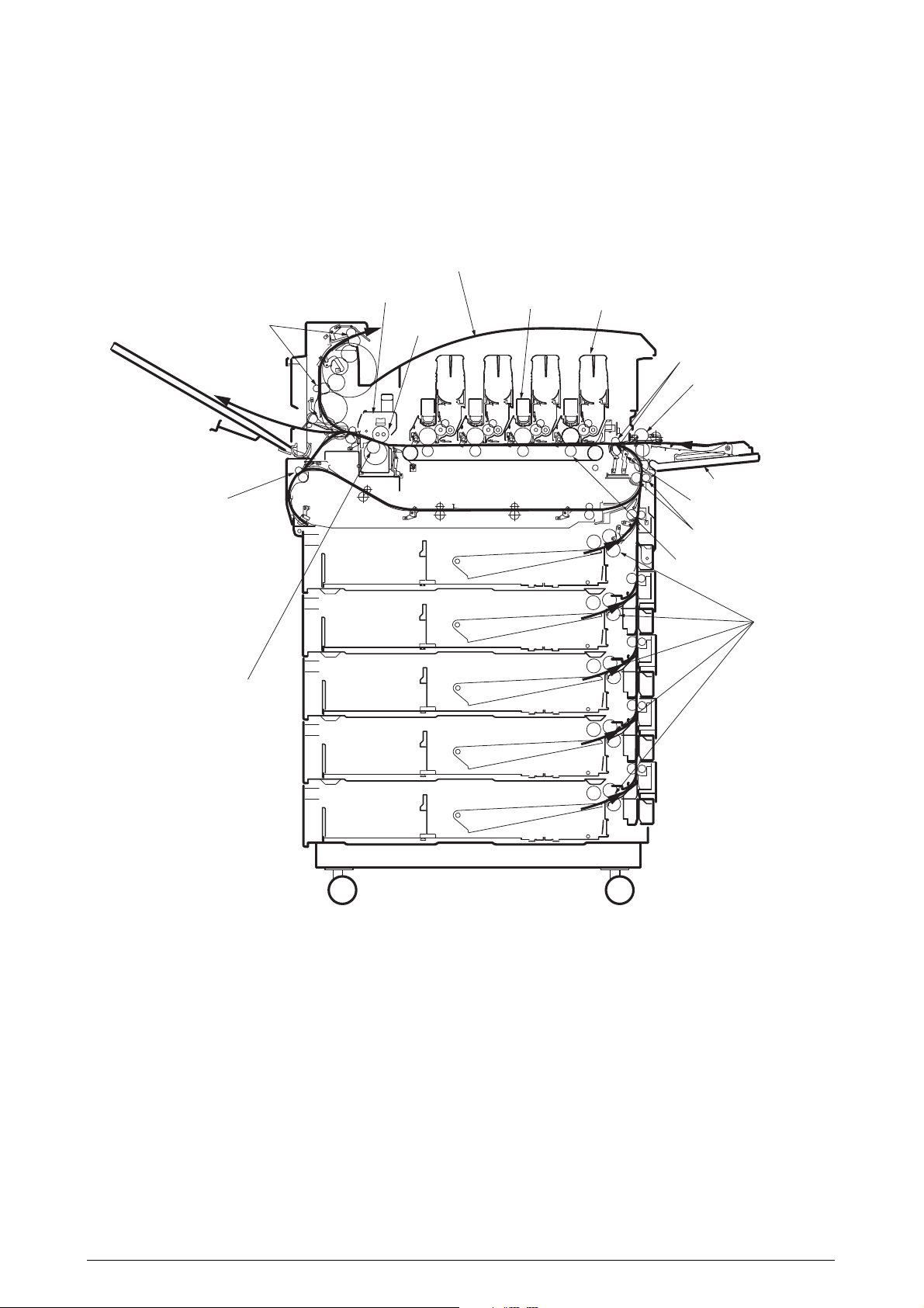
4.2 Parts Layout
Printer Unit - (120V)
Rev. 1 51 /
Page 52

Base-Assy (1/2)
A
A
Rev. 1 52 /
Page 53

Base-Assy (2/2)
Rev. 1`54 /
Page 54

Side-R-Assy
Rev. 1 55 /
Page 55

Side-F-Assy
Rev. 1 56 /
Page 56

Cover Assy-OP Panel
Rev. 1 56 /
Page 57

FDR Unit-Regist
B
A
B
A
Rev. 1 57 /
Page 58

FDR Unit-MPT
Rev. 1 58 /
Page 59

Sensor-Regist-Assy
Rev. 1 59 /
Page 60

Eject-Assy
2
Rev. 1 60 /
Page 61

Plate-Top-Assy
A
A
A
A
Rev. 1 61 /
Page 62

Job-Offset-Assy
Rev. 1 62 /
Page 63

Basket-Assy
Rev. 1 63 /
Page 64

Plate-Shield-Box-Assy
Rev. 1 64 /
Page 65

Unit-Duplex (1/2)
8
Rev. 1 65 /
Page 66

Unit-Duplex (2/2)
Rev. 1 66 /
Page 67

4.3 Parts Replacement Method
This section describes the procedures to replace the parts and assembly indicated in the disassembly
diagram.
Rev. 1 67 /
Page 68

4.3.1 Cover-Rear, Cover-Side (R), and Cover-Side (R) Rear
(1) Unscrew the 5 screws 1, then remove Cover-Rear 2.
(2) Unscrew the 2 screws 3, then remove Cover-Side (R) 4 with it warped.
(3) Unscrew the screws 3, then remove Cover-Side (R) Rear 6.
3
4
1
2
5
6
Rev. 1 68 /
Page 69

4.3.2 Cover-Side (L) and Cover Assy-Front
(1) Open Cover Assy-Top 1.
(2) Unscrew the 4 screws 2, then remove the Cover-Side (L) 3.
(3) Open the Cover Assy-Front 4 by 90°, unscrew the 2 screws 5, then slide the Assy to
the side and remove.
1
2
5
4
3
5
Rev. 1 69 /
Page 70

4.3.3 Stacker Assy-FU
(1) Open Cover Assy-Top 1.
(2) Open Stacker Assy-FU 2, then remove the 2 stoppers 3. Push these to one side, remove
the post, then remove the Stacker Assy-FU 2.
1
2
Rev. 1 70 /
Page 71

4.3.4 Cover Assy-OP Panel, Cover-Guard (R), Cover-Guard (Front) and Cover-Guard (L)
(1) Open Cover Assy-Top 1, then lift Basket-Assy 2.
(2) Remove Cover Assy-OP Panel 3 from its supporting point.
(3) Unscrew screw 4, remove the hinges, and then remove Cover-Guard (R) 5.
(4) Unscrew 2 screws 6, then remove Cover-Guard (Front) 7.
(5) Unscrew 2 screw 8, then remove the 2 hinges and remove the Cover-Guard (L) 9.
1
2
8
3
9
6
7
8
5
4
Rev. 1 71 /
Page 72

4.3.5 OP PCB
(1) Remove the Cover Assy-OP Panel. (Refer to Section 4.3.4)
(2) Remove Cover-OP Panel 2 from Frame-OP-Panel 1.
(3) Unscrew the 2 screws 3, then remove hinge (R) 4 and Cover Hinge (R) 5.
(4) Unscrew 2 screws 6, then remove the Hinge (L)7, Cover-Hinge (L)8 and Plate-Shield
(OP) 9.
(5) Remove Cover-LCD 0, Button-key A, and Lens-LED B, then remove the OP PCB C.
1
A
8
6
2
7
3
B
0
4
C
A
A
9
5
Rev. 1 72 /
Page 73

4.3.6 Cover Assy-Top
(1) Open Cover Assy-Top 1.
(2) Unscrew 8 screws 2, then remove the 3 hinges and the Cover Assy-Top 1.
1
2
× 8
Rev. 1 73 /
Page 74

4.3.7 FAN-PCB-Assy, CU-Board-Assy and S2V-PU-Board
(1) Open the Cover Assy-Top.
(2) Remove the covers concerned. (Refer to Section 4.3.2)
(3) Remove the connector, then Remove FAN-PCB-Assy 1.
(4) Unscrew the 2 screws, remove the Plate-Shield-Assy 3, then remove the connector.
(5) Unscrew 7 screws 4, then remove CU-Board-Assy 5.
(6) Disconnect all 17 Connectors, then unscrew 4 screws 6, and remove S2V-PU-Board 7.
(7) Unscrew 9 screws 8, remove the Plate-Shield-Box-Assy 9, then remove all the connec-
tors.
5
1
4 × 7
9
2
7
8 × 9
6 × 4
3
Rev. 1 74 /
Page 75

4.3.8 Job-Offset-Assy and Basket-Assy
(1) Open the Cover Assy-Top.
(2) Unscrew screw 1, remove Frame-Duct 2, then remove the connector (remove the
connector through the shaft)
(3) Remove the 2 hinges, then remove the Job-Offset-Assy 3, and disconnect the connector.
(4) Unscrew 2 screws 4, then remove the 2 hinges, and remove the Cover Assy-Top (Sub)
5.
(5) Remove the 3 E-rings 6, unscrew 2 screws 7, then remove the Plate-Support (Top) 8,
Colla 9, Shaft-Top (A) 0, Shaft-Top (B) A, Spring-Torsion-Top (L) B, Spring-Torsion-
Top (A) C, Spring-Torsion-Top (R) D and Spring-Torsion-Top (R) E.
(6) Unscrew 3 screws F, then remove the Gear-Assy-L G.
(7) Unscrew 3 screws H, then remove Gear-Assy-R I.
(8) Remove the high toner Assy tube J, then remove Basket-Assy K.
4
8
6
9
0
F
G
K
7
B
C
D
A
3
H
1
I
E
5
2
7
H
6
Rev. 1 75 /
Page 76

4.3.9 Plate Top Assy
(1) Remove Job-Offset-Assy 723/Basket-Assy. (Refer to Section 4.3.6)
(2) Lift back Plate-Top Assy 1, then unscrew 2 screws 2.
(3) Lift forward Plate-Top Assy 1, then unscrew 3 screws 3 and remove Plate-Dumper-Assy
(R)4.
(4) Remove E-ring 5, and unscrew screw 6. then remove Plate-Dumper-TCR-SUB 7 and
Dumper R 8.
(5) Unscrew 3 screws 9, then remove Plate-Dumper-Assy (L)0.
(6) Remove E-ring A, and unscrew screw B. Then remove Plate-Dumper-TCR-SUB C and
Dumper L D.
(7) Remove Shaft-Top E, Spring-Torsion-BAS (L) F, and Spring-Torsion-Top-R G, then
remove Plate-Top Assy 1.
B
A
D
1
9
F
E
2
1
G
C
9
3
0
8
5
4
6
7
Rev. 1 76 /
Page 77

4.3.10 Eject-Assy
(1) Remove the 7 hinges then remove Cover-Board 1.
(2) Remove the 13 connectors, and unscrew the 2 screws 2. Then remove the 3 hinges and
remove the Eject-Assy 3.
2
3
1
Rev. 1 77 /
Page 78

4.3.11 Motor-Pulse-Belt and Sensor-Resist-Assy
(1) Unscrew the 2 screws 1, then remove the 4-pin connector and remove the Motor-Pulse-
Belt 2.
(2) Unscrew 7 screws 3, then remove the 4 connectors (2-pin, 14-pin, 3-pin, 5-pin), and
remove the Sensor-Resist-Assy 4.
4
3
1
3
3
2
3
Rev. 1 78 /
Page 79

1
2
2
3
4.3.12 FDR Unit-MPT
(1) Open the Cover Assy-Top.
(2) Remove the stay on both side (Frontside Hook; Rear-side Screw) 4, and 2 connectors,
then unscrew the 2 screws 2.
(3) Close the hopper Assy 1, remove the 2 supporting points, then remove the FDR Unit-
MPT 3.
Branch part (two places)
Rev. 1 79 /
Page 80

4.3.13 FDR Unit-Resist
(1) Remove the FDR Unit-MPT. (Refer to Section 4.3.12)
(2) Unscrew the 4 screws 1 and disconnect connector 4, then remove Plate Assy-MPT Lock
2.
(3) Unscrew screw 3, then remove FDR Unit-Resist 5.
1
4
1
2
3
5
Rev. 1 80 /
Page 81

4.3.14 Duct Assy
(1) Remove the hinge, then remove Cover-Middle 1.
(2) Remove the hinge, then remove Guide Tube (L) 2.
(3) Unscrew 2 screws 3, then remove Duct-Assy-Toner 4.
(4) Unscrew screw 5, then remove Gear-Duct-B-Assy 6.
(5) Unscrew screw 7, then remove Gear-Duct-ID Assy 8.
(6) Unscrew 6 screws 9, then remove Duct-Drive-Assy 0.
1
9
9
0
2
7
5
8
6
3
4
Rev. 1 81 /
Page 82

4.3.15 HV-Assy
(1) Open the Cover Assy-Top, then remove the Belt-Assy.
(2) Unscrew screw 1, then remove Cover-HV-Assy 2.
(3) Remove the 2 connectors and unscrew the 2 screws 3, then remove HV-Assy 4.
(4) Remove the 2 hinges, then remove Bracket-HV-Assy 5.
2
1
3
4
5
Rev. 1 82 /
Page 83

4.3.16 Power Unit
(1)
(2) Unscrew the 12 screws 1, disconnect all connectors, pull out the lever then remove the
Power Unit 2.
2
Lever
1
× 12
Rev. 1 83 /
Page 84

4.3.17 Low Voltage Power Source Assy and Motor-FAN
(1) Remove the Power Unit. (Refer to Section 4.3.16)
(2) Unscrew the 3 screws 1, then remove the low Voltage Power Source Assy 2, and Film-
Insulation 3.
(3) Unscrew the 2 screws 4, then remove the connector and Motor-FAN 5.
1
2
3
4
5
4
Rev. 1 84 /
Page 85

4.3.18 Belt-Assy
(1) Open the Cover Assy-Top 1.
(2) Remove ID Unit 2.
(3) Lift up the 2 lock levers toward the arrow, then remove the Belt-Assy 3.
Remove Belt-Assy 3 by lifting handle 4, then remove along with handle 5.
1
2
Lock lever
3
5
4
5
4
Rev. 1 85 /
Page 86

4.3.19 Fuser Unit-LBT
(1) Open Cover Assy-Top 1.
(2) Lift the lock lever toward the arrow, then remove the Fuser Unit-LBT 2.
Lock lever
1
2
Rev. 1 86 /
Page 87

4.3.20 Unit-Duplex
(1) Pull out Unit-Duplex 1 while pressing the lever.
1
Lever
Rev. 1 87 /
Page 88

4.3.21 Paper Feed Roller
(1) Open the tray 1 side cover 1 and the paper guide 2.
(2) Pull out Tray 3.
(3) Pull outward the hinges of the 3 paper feed rollers 4, and remove from the shaft.
3
2
1
4
Hinge
Rev. 1 88 /
Page 89

2EV 89
Page 90

5. ADJUSTMENT
Adjust the AR-C360P by key input from the operation panel.
The AR-C360P comes with a Maintenance Menu in the usual menu. Select the menu according to the
items to adjust and the purpose of adjustment.
5.0 System Maintenance Menu
This menu is launched by turning on the power source while keeping the [Menu+]+[Menu-]+[Help]
switches pressed.
The menu display is only available in English regardless of destination.
Note
Category
System
Maintenance
This menu can be modified according to the destination, etc. Therefore, it is not open
(closed) to the end user.
Table 5-0. Maintenance Menu Display Table (1/2)
Item
USER
Maintenance
Menu
Maintenance
Print Menu
Value
ODA
OEL
APS
JP1
JPOEM1
OEMA
OEMI
NEXT
Enable
Disable
DF
*
*
Old Menu
"SYSTEM
MAINTENANCE
MENU" "OKIUSER" "OKIUSER"
Function
Set the destination.
JPOEM1: Japan OEM
OEMA:A4 Default Overseas OEM
OEML :
Automatically reboot after escaping
from the menu.
The default value for non-PS
models is JP1.
This displays the menu to initialize
the harddisk and Flash ROM.
This switches whether to Show/Hide
the Print Information — ID Check
Pattern and Engine Status of the
Function Menu. If this item is
disabled, the Print Information —
Status of the Function Menu is
never displayed.
The printer is restarted after the
settings are modified and escaping
from the menu.
Letter Default Overseas OEM
ID Check Pattern and Engine
Valid
RB
ET
Save
-
-
*
Print Page
Count
Personality
Diagnostic
Mode
Rev. 1 90 /
Enable
Disable
NEXT
"SYSTEM
MAINTENANCE
MENU" - "PAGE
CNT PRINT" "PAGE CNT PRINT"
"SYSTEM
MAINTENANCE
MENU""DIAGNOSTIC
MODE XX.XX"
This sets whether to Show/Hide the
display of the "Functions""Configuration" - "Print Page
Count"-"Total Page".
This displays the menu to edit the
default PDL language supported
according to destination.
This goes to the engine s selfdiagnosis mode.
ET
ET
-
-
Page 91

Table 5-0. Maintenance Menu Display Table (2/2)
Category
Maintenance
Menu
Personality
Format
Flash ROM
Item
Format HDD
Format
Flash ROM
Reset
EEPROM
Reset
Parameter
IBM PPR
III XL
EPSON
FX
HP-GL/2
Slot 0
Slot 1
Value
Execute
NEXT
Execute
Execute
Enable
Disable
Enable
Disable
Enable
Disable
Execute
Execute
DF
-
-
-
-
*E
*J
*E
*J
*JE
-
-
Old Menu
SYSTEM
MAINENANCE
MENU —
MAINTENANCE
MENU — HDD
INITIALIZE
SYSTEM
MAINENANCE
MENU -
MAINTENANCE
MENU — FLASH
INITIALIZE
SYSTEM
MAINENANCE
MENU -
MAINTENANCE
MENU — MENU
RESET
SYSTEM
MAINENANCE
MENU -
PERONALITY —
IBM PPR III XL
SYSTEM
MAINENANCE
MENU -
PERONSALITY
— EPSON fx
SYSTEM
MAINENANCE
MENU -
PERSONALITY
— hp-gl/2
Initialize the HDD. When executed it
will escape from the menu and start
initializing the HDD.
[Display Condition]
¥Mount HDD ( Boot Menu - Storage
Setup - Enable Initialization
Enable, Boot Menu - Storage
Setup - Enable HDD Yes)
This displays the menu to initialize
the Flash ROM.
This resets the EEPROM details to
the factory preset (factory default)
value. It automatically reboots after
the settings are made and applied.
* Some special items are not
initialized.
This resets the EEPROM details to
the factory preset (factory default)
value. At that time, the OEM related
settings that are not initialized with
Reset EEPROM will also be
initialized.
It automatically reboots after the
settings are made and applied.
* Some of the PU, network, etc.
cannot be initialized.
Changes the default PDL language
supported according to the destination.
The PDL language disabled from
this menu will no longer be displayed
on the Print Setup — Personality
of the Function menu. When
receiving print data in the disabled
PDL language, display INVALID
DATA and dispose the incoming
data. (HP-GL/2 is currently under
development and there are no plans
scheduled for application for the
product). PDF requires Adobe
Postscript, therefore, it is not
possible to turn PDF ON/OFF by
itself (if Adobe Postscript is
DISABLED, the PDF Function will
also be DISABLED).
It is not possible to DISABLE Adobe
Postscript and PDF with PX711/713.
(It shall be usually used in the
ENABLE state. Though DISABLE is
set the incoming data will still be
processed. It has been incorporated
for future extension purposes.)
Initialize the Flash ROM.
Escape the menu to execute, then
start formatting the Flash device
mounted on the resident (onboard).
Initialize the Flash ROM.
Escape the menu to execute, then start
formatting the Flash device mounted
on the wireless LAN (Optional).
Function
Valid
ET
RB
RB
RB
ET
ET
Save
-
-
-
-
-
-
-
During the Engine Self-Diagnosis Mode, switch operations and the LCD display is instructed by the
engine firmware, therefore, it will vary from the specifications of the controller firmware operations.
Note that the Engine Self-Diagnosis Mode can also be executed in the state with the controller PCD
removed.
For details, accordingly refer to the Engine Specifications Manual.
Rev. 1 91 /
Page 92

5.0.1 ID Check Pattern Print (“TEST PRINT MENU” Item)
This pattern can be used to investigate the cause (plain identification of problem or check cycle of
problem) resulting from the ID or LED head. CMYK are each composed of a 20% duty pattern. (printing
2 sheets)
Test Pattern Print Procedure : (Switch pressing order)
* HDD = NO : “0” → “0” → “3” → “3”
* HDD = YES : “0” → “0” → “0” → “3” → “3”
• Vertical Black/White Lines (Vertical Black/White Lines)
• Vertical Black/White Band (Vertical Black/White Band)
• Horizontal Black/White Lines (Horitzontal Black/White Lines)
• Horizontal Black/White Band (Horitzontal Black/White Band)
Print pattern (Print Pattern):
Page.1 Page.2
Y
M+Y M C K
Y
5.1 Maintenance Menu and Its Function
5.1.1 Maintenance Menu
There is a Maintenance Menu Category in a regular menu category.
The following items can be set from this menu.
M+Y
M
C
K
Rev. 1 92 /
Page 93

Maintenance Menu
Category
MAINTENANCE MENU
Item (1st Line)
EEPROM
Reset
SAVE MENU Setting
RESTORE MENU
POWER SAVE
Plain Paper Black Setting
Value (2nd Line)
EXECUTE
EXECUTE
EXECUTE
ENABLE
DISABLE
0
+1
+2
-2
-1
DF
Reset the EEPROM of the CU.
*
Save the current menu settings.
*
An ARE YOU SURE? YES/NO
selection message appears.
Modify the setting to the menu set-
*
ting saved. (Display only when
there is a menu setting saved)
Note
This sets the ENABLE/DISABLE of
*
the power save mode.
When the power save mode is enabled, the time it takes to activate
the power save mode can be modified by the Power Save Delay Time
Item in the System Config Menu.
Plain Paper/Black Print: This fine-
*
tunes any uneven printing or dust in
the printouts. Decrement this setting if there is any scattering in high
density printing or if there is snowlike patterns in the printout. Increment this setting if the printout appears whiting out.
Function
Saved on the Flash
(surface-mounted) of the
CU. Saved on the HDD if
there is a HDD.
Plain Paper Color Setting
Transparency Black
Setting
Transparency Color
Setting
0
+1
+2
-2
-1
0
+1
+2
-2
-1
0
+1
+2
-2
-1
Plain Paper/COLOR Print: This is
*
used to fine-tune any uneven printing or dust in the printouts. Decrement this setting if there is any
scattering in high density printing or
if there is snow-like patterns in the
printout. Increment this setting if the
printout appears whiting out.
Transparency/BLACK Print: This is
*
used to fine-tune any uneven printing or dust in the printouts Decrement this setting if there is any
scattering in high density printing or
if there is snow-like patterns in the
printout. Increment this setting if the
printout appears whiting out.
Transparency/COLOR Print: This is
*
used to fine-tune any uneven printing or dust in the printouts Decrement this setting if there is any
scattering in high density printing or
if there is snow-like patterns in the
printout. Increment this setting if the
printout appears whiting out.
Rev. 1 93 /
Page 94

5.1.2 Engine Maintenance Mode
Engine maintenance mode is a media conveyor mode that assists confirmation of the basic operations
of the check and print system.
5.1.2.1 Operation Panel
Instructions on self-diagnosis operations is based on the following Operation Panel layout, as a
prerequisite.
Rev. 1 94 /
Page 95

5.1.2.2 Regular Self-Diagnosis Mode (Level 1)
The Regular Self-Diagnosis Mode menu is as follows.
• Switch Scan Test
• Motor and Clutch Test
• Execute Test Pattern
• Initialize NVM
• Consumable Counter Display
• Consumable Continual Counter Display
5.1.2.2.1 How to Enter Self-Diagnosis Mode (Level 1)
1. Press the [MENU+], [MENU-] and [HELP] keys at the same time when turning ON the
power to go to the System Maintenance Mode.
2. Press the [MENU+] and [MENU-] key until the “DIAGNOSTIC MODE” is displayed.
DIAGNOSTIC MODE
XX.XX.XX S-MODE
3. “Diagnostic Mode XX.XX.XX” appears on the LCD panel. The XX.XX.XX stands for the
version of the ROM. At the bottom right the setting of the “Factory Working Mode” is
displayed. This is usually “S-MODE”.
4. Press the [MENU+] or [MENU-] key to go to each self-diagnostic step. (The menu item
rotates by pressing the [MENU+] or [MENU-] keys)
5.1.2.2.2 Escape from Self-Diagnosis Mode
1. Turn OFF the power then turn it back ON after 10 seconds.
Rev. 1 95 /
Page 96

5.1.2.3 Switch Scan Test
This self-diagnosis is sued to check the input sensor and switch.
SWITCH SCAN
1. Keep the [MENU+] and [MENU-] keys pressed until [SWITCH SCAN] appears at the top
of the display and operations goes into the regular diagnosis mode. (The [MENU+] key
= Increment Test Item / the [MENU-] key = Decrement Test Item.)
2. The following message appears by pressing [ENTER]
SWITCH SCAN
PAPER ROUTE: PU
3. Keep the [MENU+] and [MENU-] keys pressed until the item that applies to the unit to
test from Table 5-1-1 appears, at the top of the display.
Press the [
[MENU-] key
MENU+] and [MENU-] keys
= Decrement Test Item.
. The [MENU+] key = Increment Test Item /
the
PAPER ROUTE: PU
1=H 2=L 3=H 4=L
4. The test is started by pressing the [ENTER] key. The top of the display starts blinking and
the applicable unit number (1-4) and the current state appears.
Operate each unit (Figure 5-1). Display the operations on each respective applicable LCD
area. (The display varies according to each sensor. For details refer to Table 5-1-1.)
5. Press the [CANCEL] or [BACK] key to return to state 2.
6. Accordingly repeat Steps 2 to 4.
7. To end the test press the [BACK] key. (Return to state 1)
Rev. 1 96 /
Page 97

No5-1 Stacker Full FD SNS
No32-1
Dup IN1 SNS
15-1 MPT PE SNS
15-2 MPT PE SNS2
16-1 MPT Hopping SNS
8-1 Hum SNS, 8-2 Temp SNS
6-4 Media Weight SNS
1-3 WR SNS
1-2 IN2 SNS
16-2 MPT Home SNS
1-1 IN1 SNS
18-1 1stHopping SNS
32-3 Dup F SNS
6-1,2 Alignment L,R SNS
33-1 Dup IN2 SNS
No19-1~No19-4
1stPaper Size SW
No5-4 JobOffset HP SNS
No22-1~No22-4
1stPaper Size SW
21-1 2ndHopping SNS
20-2 2ndPaper Near END SNS
20-1 2ndPaper END SNS
21-2 2ndLifter SNS
21-3 2ndFeed SNS
20-3 Cover Open 2nd SW
17-2 1stPaper Near END SNS
17-1 1stPaper END SNS
18-2 1stLifter SNS
18-3 1stFeed SNS
17-3 Cover Open 1st SW
13-2 Disposal toner box
12-4 Waste Toner Hole IC
12-3 Belt Hole IC
4-1 Cover Upper
15-3 Cover MPT
No10-1 TAG (K)
No10-1 TAG (K)
No10-2 TAG (Y)
No10-3 TAG (M)
No10-4 TAG (C)
No5-2
Stacker Full FU SNS
No5-3
Job off Paper Back End SNS
No4-3 Cover Face Up
No4-2 Cover Left Upper
1-4 Exit SNS
12-2
Paper Slack SNS
12-1 Fuser Release SNS
32-2
Dup R SNS
15-3 Cover MPT
8-1 Hum SNS, 8-2 Temp SNS
6-4 Media Weight SNS
15-1 MPT PE SNS
15-2 MPT PE SNS2
16-1 MPT Hopping SNS
16-2 MPT Home SNS
1-2 IN2 SNS
17-3 Cover Open 1st SW
1-1 IN1 SNS
18-1 1stHopping SNS
18-3 1stFeed SNS
20-3 Cover Open 2nd SW
21-1 2ndHopping SNS
21-3 2ndFeed SNS
No10-2 TAG (Y)
No10-3 TAG (M)
No10-4 TAG (C)
No5-1 Stacker Full FD SNS
12-2
Paper Slack SNS
1-4 Exit SNS
No5-3
Job off Paper Back End SNS
4-1 Cover Upper
12-4 Waste Toner Hole IC
12-3 Belt Hole IC
1-3 WR SNS
32-3 Dup F SNS
13-2 Disposal toner box
6-1,2 Alignment L,R SNS
32-2
Dup R SNS
12-1 Fuser Release SNS
33-1 Dup IN2 SNS
17-2 1stPaper Near END SNS
18-2 1stLifter SNS
17-1 1stPaper END SNS
20-2 2ndPaper Near END SNS
20-1 2ndPaper END SNS
21-2 2ndLifter SNS
Figure 5-1 Location of Switching Sensor
No32-1
No5-4 JobOffset HP SNS
No4-3 Cover Face Up
No4-2 Cover Left Upper
Dup IN1 SNS
No5-2
Stacker Full FU SNS
No19-1~No19-4
1stPaper Size SW
No22-1~No22-4
1stPaper Size SW
Rev. 1 97 /
Page 98

Table 5-1-1 Switch Scan Details
No.
1
2
3
4
5
6
7
8
9
10
11
12
13
14
15
16
17
18
19
20
21
22
23
24
25
26
27
28
29
30
31
Top of the
Display Display
PAPER ROUTE
: PU
PAPER ROUTE
: SUB
TONER SENS
COVER
UP_LU_FU
STKF_FD_FU
JOBOFFHOME
REG L/R_
DENS_WEIGHT
HEATER
THERMISTER
HUM_TEMP_OHP
ID UP/DOWN
RFID COLOR
DRUM PHASE
SNS KYMC
F-RLS SLK BLT
DT-DCT
DISTNR
FULL_BOX_BOXSP
TNR SPLY SNS
KY_MC
MPT PE_
HOP_CVO_HOME
TRAY1 PE_
PNE_CVO
TRAY1
HOP_LIFT
TRAY1 CASETTE
SIZE
TRAY2
PE_PNE_CVO
TRAY2
HOP_LIFT_FEED
TRAY2 CASETTE
SIZE
TRAY3
PE_PNE_CVO
TRAY3
HOP_LIFT_FEED
TRAY3 CASETTE
SIZE
TRAY4
PE_PNE_CVO
TRAY4
HOP_LIFT_FEED
TRAY4 CASETTE
SIZE
TRAY5
PE_PNE_CVO
TRAY5
HOP_LIFT_FEED
TRAY5 CASETTE
SIZE
DUP INS_
REAR_FRONT
IN1 Sns
IN1 Sns
Toner-K Sns
Cover-Upper
Stacker Full Sns
(Face down)
Aligment-LeftSns
Upper-CenterThermister
Hum Sns
TAG-K presence
K-Drum Phase
Sns
Fuser Release
Sns
Disposal toner
full
K-Toner Supply
Sns
MPT-Paper-End
Sns
1st-Paper-End
Sns
1st-Hopping
Sns
1st-Paper Size1 Sw
2nd-Paper-End
Sns
2nd-Hopping
Sns
2nd-Paper Size1 Sw
3rd-Paper-End
Sns
3rd-Hopping
Sns
3rd-Paper Size1 Sw
4th-Paper-End
Sns
4th-Hopping
Sns
4th-Paper Size1 Sw
5th-Paper-End
Sns
5th-Hopping
Sns
5th-Pape rSize1 Sw
Dup-In Sns
1
Detail
H:OFF
L:ON
H:OFF
L:ON
H:ON
L:OFF
H:Open
L:Close
H:Full
L:Empty
AD Value:
***H
AD Value:
***H
AD Value:
***H
UID:****H
Port Level
H, L
H:ON
L:OFF
H:ON
L:OFF
Port Level
H, L
Port Level
H, L
Port Level
H, L
Port Level
H, L
Port Level
H, L
Port Level
H, L
Port Level
H, L
Port Level
H, L
Port Level
H, L
Port Level
H, L
Port Level
H, L
Port Level
H, L
Port Level
H, L
Port Level
H, L
Port Level
H, L
Port Level
H, L
Port Level
H, L
Port Level
H, L
2
Detail Display
IN2 Sns
IN2 Sns
Toner-Y Sns
Cover-Left
Upper
Stacker Full Sns
(Face up)
Aligment-RightSns
Lower-CenterThermister
Temperture-Sns
TAG-Y presence
Y-Drum Phase
Sns
Paper Slack
Sns
Disposal toner
box
Y-Toner Supply
Sns
MPT-Hopping
Sns
1st-Paper-NearEnd Sns
1st-Lifter Sns
1st-Paper Size2 Sw
2nd-PaperNear-End Sns
2nd-Lifter Sns
2nd-Paper Size2 Sw
3rd-Paper-NearEnd Sns
3rd-Lifter Sns
3rd-Paper Size2 Sw
4th-Paper-NearEnd Sns
4th-Lifter Sns
4th-Paper Size2 Sw
5th-Paper-NearEnd Sns
5th-Lifter Sns
5th-Paper Size2 Sw
Dup-Rear Sns
H:OFF
L:ON
H:OFF
L:ON
H:ON
L:OFF
H:Open
L:Close
H:Full
L:Empty
AD Value:
***H
AD Value:
***H
AD Value:
***H
UID:****H
Port Level
H, L
H:ON
L:OFF
H:Not
installed
L:Installed
Port Level
H, L
H:ON
L:OFF
Port Level
H, L
Port Level
H, L
Port Level
H, L
Port Level
H, L
Port Level
H, L
Port Level
H, L
Port Level
H, L
Port Level
H, L
Port Level
H, L
Port Level
H, L
Port Level
H, L
Port Level
H, L
Port Level
H, L
Port Level
H, L
Port Level
H, L
Port Level
H, L
3
Detail Display
WR Sns
WR Sns
Toner-M Sns
Cover-Face Up
Job Offset
Paper-End Sns
Upper-SideThermister
OHP Sns
TAG-M presence
M-Drum Phase
Sns
Belt Hole IC
M-Toner Supply
Sns
Cover-MPT
Cover-1st
1st-Feed Sns
1st-Paper Size3 Sw
Cover-Open2nd Sw
2nd-Feed Sns
2nd-Paper Size3 Sw
Cover-Open-3rd
Sw
3rd-Feed Sns
3rd-Paper Size3 Sw
Cover-Open-4th
Sw
4th-Feed Sns
4th-Paper Size3 Sw
Cover-Open-5th
Sw
5th-Feed Sns
5th-Paper Size3 Sw
Dup-Front Sns
H:OFF
L:ON
H:OFF
L:ON
H:ON
L:OFF
H:Open
L:Close
H:ON
L:OFF
AD Value:
***H
AD Value:
***H
UID:****H
Port Level
H, L
H:ON
L:OFF
Port Level
H, L
H:Open
L:Close
H:Open
L:Close
Port Level
H, L
Port Level
H, L
Port Level
H, L
Port Level
H, L
Port Level
H, L
Port Level
H, L
Port Level
H, L
Port Level
H, L
Port Level
H, L
Port Level
H, L
Port Level
H, L
Port Level
H, L
Port Level
H, L
Port Level
H, L
Port Level
H, L
4
Detail Display
Exit Sns
Toner-C Sns
JobOffset Home
Position Sns
Media WeigtSns
Detect-ambient
temperatureThermister
ID UpDown Sns
TAG-C presence
C-Drum Phase
Sns
Waste Toner
Hole IC
C-Toner Supply
Sns
MPT Home
Position Sns
1st-Paper Size4 Sw
2nd-Paper Size4 Sw
3rd-Paper Size4 Sw
4th-Paper Size4 Sw
5th-Pape Size-4
Sw
H:OFF
L:ON
H:ON
L:OFF
H:ON
L:OFF
Frequency
AD Value:
***H
H:Up
L:Down
UID:****H
Port Level
H, L
H:ON
L:OFF
Port Level
H, L
H:Open
L:Close
Port Level
H, L
Port Level
H, L
Port Level
H, L
Port Level
H, L
Port Level
H, L
Rev. 1 98 /
Page 99

No.
32
33
34
35
36
37
38
39
40
41
42
43
Top of the
Display Display
DUP
STACK_COVER
FIN S01_S02_
S03_S04
FIN S05_S06_
S07_S08
FIN S09_S10_
S11_S12
FIN S13_S14_
S15_S16
FIN S17_S18_
S19_S20
FIN S21_S22_
S23_S24
FIN S25_S26_
S27_S28
FIN S29_S30_
S31_S32
INV IN_OUT_
EXIT_COV
INV REMAIN_
JOINT
HALL BELT_
DT-BOX_DCT
Dup-Stack Sns
Uper Cover Sns
[PI23]
Bookbinding
position
Sns[PI10]
Bookbinding
tray paper Sns
[PI13]
Rear matching
home position
Sns [PI5]
Staple / fold
motor clock
[PI14]
Staple home
position
Sns[PI19]
Lower stack tray
Sns [PI16]
Stack tray paper
Sns [PI8]
Entrance Sns
[FP1]
Lower Sns[FP3]
Belt Hole IC
1
Detail
Port Level
H, L
H:OPEN
L:CLOSE
H:Paper
present
L:Paper
absent
H:Paper
present
L:Paper
absent
H:Home
position
L:Except in
the home
position
H/L:Clock
H:Home
position
L:Except in
the home
position
H:Lower
position
L:Except in
the lower
position
H:Paper
present
L:Paper
absent
H:ON
L:OFF
H:ON
L:OFF
H:ON
L:OFF
2
Detail Display
Dup-Cover
Open Sns
Front door Sns
[PI22]
Processing tray
Sns [PI6]
Bookbinding
home position
Sns [PI11]
Belt home
position outlet
Sns [PI7]
Self prime Sns
[PI21]
Stapler slide
home position
Sns [PI18]
Upper stack tray
Sns [PI15]
Punch connect
signal
Outlet Sns
[FP2]
Inverter
connected Sns
[FP4]
Waste Toner
Box Hole IC
Port Level
H, L
H:OPEN
L:CLOSE
H:Paper
present
L:Paper
absent
H:Home
position
L:Except in
the home
position
H:Home
position
L:Except in
the home
position
H:Start
staple
detection
L:Staple
absent
H:Home
position
L:Except in
the home
position
H:Upper
position
L:Except in
the upper
position
Hconnected
Lunconnected
H:ON
L:OFF
H:ON
L:OFF
H:ON
L:OFF
3
Detail Display
Front door SW
[MS2]
Entrance Sns
[PI1]
Bookbinding
roller home
position Sns
[PI12]
Feed roller
home position
Sns[PI3]
Staple Sns
[PI20]
Stapler connect
signal
Interlevel stack
tray Sns [PI24]
PU→Inverter
Exit Sns Signal
PU→Inverter
CNT2 Signal
Waste Toner
Hole IC
H:OPEN
L:CLOSE
H:Paper
present
L:Paper
absent
H:Home
position
L:Except in
the home
position
H:Home
position
L:Except in
the home
position
H:Staple
absent
L:Staple
present
Hconnected
Lunconnected
H:Interlevel
detection
L:Interlevel
undetection
H:ON
L:OFF
H:ON
L:OFF
H:ON
L:OFF
4
Detail Display
Joint SW [MS1]
Punch timing
Sns
Front matching
home position
Sns [PI4]
Paddle home
position [PI2]
Stapler safty
SW [MS3]
Stack tray lift
motor
clock[PI17]
Paper stack tray
Sns [PI9]
Cover open SW
[FMS1]
H:OPEN
L:CLOSE
H:Paper
present
L:Paper
absent
H:Home
position
L:Except in
the home
position
H:Home
position
L:Except in
the home
position
H:Not to
drive
L:Drive
H/L:Clock
H:Paper
detect position
L:Except in
the paper
detect position
H:Open
L:Close
Table 5-1-2 Paper Size Detection, Various Paper Types and Bits
No.
0
1
2
3
4
5
6
7
8
9
A
B
C
D
E
F
Rev. 1 99 /
Paper
No cassette
B5-L
Legal 13-S
B5-S
A4-L
Letter-L
A5-S
A4-S
B4-S
A3-S
Legal 14-S
Executive-S
A3nobi-S
Ledger-S
A6-S
Letter-S
1
H
L
H
L
H
L
H
L
H
L
H
L
H
L
H
L
2
H
H
L
L
H
H
L
L
H
H
L
L
H
H
L
L
3
H
H
H
H
L
L
L
L
H
H
H
H
L
L
L
L
4
H
H
H
H
H
H
H
H
L
L
L
L
L
L
L
L
Page 100

5.1.2.4 Motor/Clutch Test
This self-diagnosis routine is used to test the motor and clutch.
1. Continue to press the [MENU+] and [MENU-] keys until “MOTOR & CLUTCH TEST”
appears at the top of the display and the operation enters the self-diagnosis (Level 1)
mode.
The [MENU+] key = Increment Test Item / the [MENU-] key = Decrement Test Item.
2. The following message appears when the [ENTER] is pressed. The suitable location of
the unit to be tested as shown in Table 5-2 will appear at the bottom of the display.
Press the [MENU+] and [MENU-] keys.
The [MENU+] key = Increment Test Item / the [MENU-] key = Decrement Test Item.
MOTOR & CLUTCH TEST
PK – ID MOTOR
3. Press the [ENTER] key to start the test. The name of the unit will start blinking. Then the
applicable unit will drive for 10 seconds.
Note
After driving for 10 seconds, it will return to State 2. The drive will start again by
re-pressing the applicable switch.
• To drive the applicable unit, there is a need to clear the drive limitational conditions
indicated in Table 5-2. Launching a state drive that doesn’t clear the limitation conditions
is invalid. When this happens the clear information is displayed at the bottom of the
display.
• The clutch solenoid generally repeats ON/OFF with regular printer driver. (models that
do not drive independently due to its mechanical structure will come be driven by a
motor.)
4. Press the [CANCEL] key to stop the applicable unit drive. (maintain the display of the
applicable unit, at this time)
5. Accordingly repeat Steps 2 to 4.
6. Press the [BACK] key to end the test. (Returns to state 1)
Rev. 1 100 /
 Loading...