

Page 1
SERVICE MANUAL
CODE: 00ZARC260MA2E
DIGITAL FULL COLOR COPIER/PRINTER/
MULTIFUNCTIONAL SYSTEM
AR-C260
(AR-C260, AR-C260M)
[10] MAINTENANCE LIST . . . . . . . . . . . . . . . . . . . . . . . . . . . . . . . . . . 10-1
MODEL
CONTENTS
[1] OUTLINE . . . . . . . . . . . . . . . . . . . . . . . . . . . . . . . . . . . . . . . . . . . . 1-1
[2] CONFIGURATION . . . . . . . . . . . . . . . . . . . . . . . . . . . . . . . . . . . . . 2-1
[3] SPECIFICATIONS . . . . . . . . . . . . . . . . . . . . . . . . . . . . . . . . . . . . . 3-1
[4] CONSUMABLE PARTS . . . . . . . . . . . . . . . . . . . . . . . . . . . . . . . . . 4-1
[5] UNPACKING AND INSTALLATION . . . . . . . . . . . . . . . . . . . . . . . . 5-1
[6] EXTERNAL VIEW AND INTERNAL STRUCTURE . . . . . . . . . . . . 6-1
[7] DESCRIPTIONS OF EACH SECTION. . . . . . . . . . . . . . . . . . . . . . 7-1
[8] SETTING AND ADJUSTMENTS . . . . . . . . . . . . . . . . . . . . . . . . . . 8-1
[9] SIMULATION . . . . . . . . . . . . . . . . . . . . . . . . . . . . . . . . . . . . . . . . . 9-1
AR-C260M
[11] TROUBLESHOOTING . . . . . . . . . . . . . . . . . . . . . . . . . . . . . . . . . 11-1
[12] ROM VERSION UP . . . . . . . . . . . . . . . . . . . . . . . . . . . . . . . . . . . 12-1
[13] ELECTRIC DIAGRAM . . . . . . . . . . . . . . . . . . . . . . . . . . . . . . . . . 13-1
[14] OTHERS. . . . . . . . . . . . . . . . . . . . . . . . . . . . . . . . . . . . . . . . . . . . 14-1
Parts marked with “ ” are important for maintaining the safety of the set. Be sure to replace these parts with
specified ones for maintaining the safety and performance of the set.
This document has been published to be used
SHARP CORPORATION
for after sales service only.
The contents are subject to change without notice.
Page 2

[1] OUTLINE
1. Product features. . . . . . . . . . . . . . . . . . . . . . . . . . . . . . . . . . . . . . . . . . . 1-1
2. Newly employed technology . . . . . . . . . . . . . . . . . . . . . . . . . . . . . . . . . 1-1
[2] CONFIGURATION
1. Product Line and options . . . . . . . . . . . . . . . . . . . . . . . . . . . . . . . . . . . . 2-1
A. Line of machines . . . . . . . . . . . . . . . . . . . . . . . . . . . . . . . . . . . . . . . 2-1
B. Line of options . . . . . . . . . . . . . . . . . . . . . . . . . . . . . . . . . . . . . . . . . 2-1
C. Combination of options . . . . . . . . . . . . . . . . . . . . . . . . . . . . . . . . . . 2-2
2. Block diagram . . . . . . . . . . . . . . . . . . . . . . . . . . . . . . . . . . . . . . . . . . . . 2-2
[3] SPECIFICATIONS
1. Basic specifications . . . . . . . . . . . . . . . . . . . . . . . . . . . . . . . . . . . . . . . . 3-1
A. Base engine. . . . . . . . . . . . . . . . . . . . . . . . . . . . . . . . . . . . . . . . . . . 3-1
B. Paper feed unit . . . . . . . . . . . . . . . . . . . . . . . . . . . . . . . . . . . . . . . . 3-2
C. Paper exit unit . . . . . . . . . . . . . . . . . . . . . . . . . . . . . . . . . . . . . . . . . 3-2
D. Scanner section. . . . . . . . . . . . . . . . . . . . . . . . . . . . . . . . . . . . . . . . 3-2
2. Functional specifications . . . . . . . . . . . . . . . . . . . . . . . . . . . . . . . . . . . . 3-3
A. Specifications of copy functions. . . . . . . . . . . . . . . . . . . . . . . . . . . . 3-3
3. Environment conditions . . . . . . . . . . . . . . . . . . . . . . . . . . . . . . . . . . . . . 3-5
A. Operating environment conditions . . . . . . . . . . . . . . . . . . . . . . . . . . 3-5
B. Storage environment conditions . . . . . . . . . . . . . . . . . . . . . . . . . . . 3-5
C. Transit environment conditions . . . . . . . . . . . . . . . . . . . . . . . . . . . . 3-6
D. Standard temperature and humidity . . . . . . . . . . . . . . . . . . . . . . . . 3-6
[4] CONSUMABLE PARTS
1. Supply system table . . . . . . . . . . . . . . . . . . . . . . . . . . . . . . . . . . . . . . . . 4-1
2. Consumables (kit, unit) . . . . . . . . . . . . . . . . . . . . . . . . . . . . . . . . . . . . . 4-2
3. Photoconductor, developer, toner . . . . . . . . . . . . . . . . . . . . . . . . . . . . . 4-3
[5] UNPACKING AND INSTALLATION
1. Installing (use) conditions. . . . . . . . . . . . . . . . . . . . . . . . . . . . . . . . . . . . 5-1
2. Transit and delivery . . . . . . . . . . . . . . . . . . . . . . . . . . . . . . . . . . . . . . . . 5-2
3. Unpacking . . . . . . . . . . . . . . . . . . . . . . . . . . . . . . . . . . . . . . . . . . . . . . . 5-2
4. Lock release . . . . . . . . . . . . . . . . . . . . . . . . . . . . . . . . . . . . . . . . . . . . . . 5-3
5. Fusing heat roller pressing (F/R) . . . . . . . . . . . . . . . . . . . . . . . . . . . . . . 5-4
6. Black drum cartridge insertion . . . . . . . . . . . . . . . . . . . . . . . . . . . . . . . . 5-5
7. Paper exit tray installation . . . . . . . . . . . . . . . . . . . . . . . . . . . . . . . . . . . 5-5
8. Toner cartridges installation . . . . . . . . . . . . . . . . . . . . . . . . . . . . . . . . . . 5-5
9. AC cord connection . . . . . . . . . . . . . . . . . . . . . . . . . . . . . . . . . . . . . . . . 5-6
10. Machine power ON . . . . . . . . . . . . . . . . . . . . . . . . . . . . . . . . . . . . . . . . 5-6
11. Specifications setup . . . . . . . . . . . . . . . . . . . . . . . . . . . . . . . . . . . . . . . . 5-6
12. Image quality check . . . . . . . . . . . . . . . . . . . . . . . . . . . . . . . . . . . . . . . . 5-6
13. Function and operation check. . . . . . . . . . . . . . . . . . . . . . . . . . . . . . . . . 5-6
14. Setup and adjustment data recording . . . . . . . . . . . . . . . . . . . . . . . . . . 5-7
15. Necessary works before moving the machine . . . . . . . . . . . . . . . . . . . . 5-7
[6] EXTERNAL VIEW AND INTERNAL STRUCTURE
1. Name and function of each section . . . . . . . . . . . . . . . . . . . . . . . . . . . . 6-1
A. External view . . . . . . . . . . . . . . . . . . . . . . . . . . . . . . . . . . . . . . . . . . 6-1
B. Internal structure . . . . . . . . . . . . . . . . . . . . . . . . . . . . . . . . . . . . . . . 6-2
C. Operation panel . . . . . . . . . . . . . . . . . . . . . . . . . . . . . . . . . . . . . . . . 6-3
D. Job status display . . . . . . . . . . . . . . . . . . . . . . . . . . . . . . . . . . . . . . 6-4
E. Cross section . . . . . . . . . . . . . . . . . . . . . . . . . . . . . . . . . . . . . . . . . . 6-5
F. Motors, clutches, solenoids, fans. . . . . . . . . . . . . . . . . . . . . . . . . . . 6-7
G. Sensors, switches and heaters . . . . . . . . . . . . . . . . . . . . . . . . . . . . 6-8
H. PWB 1 . . . . . . . . . . . . . . . . . . . . . . . . . . . . . . . . . . . . . . . . . . . . . . . 6-9
H. PWB 2 . . . . . . . . . . . . . . . . . . . . . . . . . . . . . . . . . . . . . . . . . . . . . . 6-10
[7] DESCRIPTIONS OF EACH SECTION
1. Fusing section . . . . . . . . . . . . . . . . . . . . . . . . . . . . . . . . . . . . . . . . . . . . 7-1
A. Operational descriptions . . . . . . . . . . . . . . . . . . . . . . . . . . . . . . . . . 7-1
B. Disassembly/Assembly/Maintenance . . . . . . . . . . . . . . . . . . . . . . . 7-3
2. Transfer section . . . . . . . . . . . . . . . . . . . . . . . . . . . . . . . . . . . . . . . . . . . 7-7
A. Operational descriptions . . . . . . . . . . . . . . . . . . . . . . . . . . . . . . . . . 7-7
B. Disassembly/assembly/maintenance. . . . . . . . . . . . . . . . . . . . . . . 7-10
3. Process (image forming) section . . . . . . . . . . . . . . . . . . . . . . . . . . . . . 7-15
A. Operational descriptions . . . . . . . . . . . . . . . . . . . . . . . . . . . . . . . . 7-15
B. Disassembly/assembly/maintenance. . . . . . . . . . . . . . . . . . . . . . . 7-19
4. Optical section (Scanner section) . . . . . . . . . . . . . . . . . . . . . . . . . . . . 7-22
A. Operational descriptions . . . . . . . . . . . . . . . . . . . . . . . . . . . . . . . . 7-22
B. Disassembly/assembly/maintenance. . . . . . . . . . . . . . . . . . . . . . . 7-25
5. Paper feed, paper transport, and paper exit sections . . . . . . . . . . . . . 7-27
A. Operational descriptions . . . . . . . . . . . . . . . . . . . . . . . . . . . . . . . . 7-27
B. Disassembly/assembly/maintenance. . . . . . . . . . . . . . . . . . . . . . . 7-33
6. Operation panel . . . . . . . . . . . . . . . . . . . . . . . . . . . . . . . . . . . . . . . . . . 7-40
A. Operational descriptions . . . . . . . . . . . . . . . . . . . . . . . . . . . . . . . . 7-40
B. Disassembly/assembly/maintenance. . . . . . . . . . . . . . . . . . . . . . . 7-41
7. External fitting . . . . . . . . . . . . . . . . . . . . . . . . . . . . . . . . . . . . . . . . . . . 7-42
A. Disassembly . . . . . . . . . . . . . . . . . . . . . . . . . . . . . . . . . . . . . . . . . 7-42
8. Others . . . . . . . . . . . . . . . . . . . . . . . . . . . . . . . . . . . . . . . . . . . . . . . . . 7-44
A. Disassembly/assembly/maintenance. . . . . . . . . . . . . . . . . . . . . . . 7-44
CONTENTS
[8] SETTING AND ADJUSTMENTS
[ADJ 1] High voltage adjustment . . . . . . . . . . . . . . . . . . . . . . . . . . . . . . . .8-2
[ADJ 2] Image density sensor adjustment . . . . . . . . . . . . . . . . . . . . . . . . .8-4
[ADJ 3] Image focus, image skew adjustment
(LED (writing) unit) . . . . . . . . . . . . . . . . . . . . . . . . . . . . . . . . . . . . 8-6
[ADJ 4] Image registration adjustment. . . . . . . . . . . . . . . . . . . . . . . . . . . . 8-9
[ADJ 5] Image position/print area adjustment
(Print engine section) . . . . . . . . . . . . . . . . . . . . . . . . . . . . . . . . . 8-15
[ADJ 6] Copy image distortion adjustment. . . . . . . . . . . . . . . . . . . . . . . . 8-16
[ADJ 7] Copy image focus (main scanning direction copy
magnification ratio) adjustment
(CCD unit position adjustment) . . . . . . . . . . . . . . . . . . . . . . . . . . 8-19
[ADJ 8] Sub scanning direction copy magnification ratio
adjustment . . . . . . . . . . . . . . . . . . . . . . . . . . . . . . . . . . . . . . . . .8-20
[ADJ 9] Main scanning direction copy image position
adjustment (Scanner (reading) section) . . . . . . . . . . . . . . . . . . .8-20
[ADJ 10] Copy image position/image loss/void area adjustment. . . . . . . . 8-21
[ADJ 11] Copy color balance/density adjustment . . . . . . . . . . . . . . . . . . . 8-22
[ADJ 12] Fusing pressure adjustment . . . . . . . . . . . . . . . . . . . . . . . . . . . . 8-36
[ADJ 13] Fusing paper guide position adjustment . . . . . . . . . . . . . . . . . . .8-36
[ADJ 14] Document size sensor adjustment . . . . . . . . . . . . . . . . . . . . . . . 8-37
[ADJ 15] Manual paper feed tray paper size sensor adjustment. . . . . . . .8-37
[ADJ 16] Touch panel coordinates setting . . . . . . . . . . . . . . . . . . . . . . . . .8-38
[ADJ 17] Power voltage adjustment. . . . . . . . . . . . . . . . . . . . . . . . . . . . . . 8-38
[ADJ 18] FAX/scanner mode image loss adjustment . . . . . . . . . . . . . . . .8-38
[9] SIMULATION
1. Outline and purpose . . . . . . . . . . . . . . . . . . . . . . . . . . . . . . . . . . . . . . . . 9-1
2. Code-type simulation. . . . . . . . . . . . . . . . . . . . . . . . . . . . . . . . . . . . . . . .9-1
A. Operating procedures and operations. . . . . . . . . . . . . . . . . . . . . . . . 9-1
B. Simulation list . . . . . . . . . . . . . . . . . . . . . . . . . . . . . . . . . . . . . . . . . . 9-3
C. Details . . . . . . . . . . . . . . . . . . . . . . . . . . . . . . . . . . . . . . . . . . . . . . . 9-13
[10] MAINTENANCE LIST
1. Maintenance system table . . . . . . . . . . . . . . . . . . . . . . . . . . . . . . . . . . . 10-1
2. List . . . . . . . . . . . . . . . . . . . . . . . . . . . . . . . . . . . . . . . . . . . . . . . . . . . . .10-2
A. Drum peripheral section . . . . . . . . . . . . . . . . . . . . . . . . . . . . . . . . . 10-2
B. Developing section . . . . . . . . . . . . . . . . . . . . . . . . . . . . . . . . . . . . . 10-2
C. Transfer section . . . . . . . . . . . . . . . . . . . . . . . . . . . . . . . . . . . . . . . 10-3
D. Fusing section . . . . . . . . . . . . . . . . . . . . . . . . . . . . . . . . . . . . . . . . . 10-4
E. Optical section (Scanner section) . . . . . . . . . . . . . . . . . . . . . . . . . .10-5
F. Paper feed section, transport section . . . . . . . . . . . . . . . . . . . . . . .10-6
G. LED . . . . . . . . . . . . . . . . . . . . . . . . . . . . . . . . . . . . . . . . . . . . . . . . . 10-6
H. Filters, drive section, others . . . . . . . . . . . . . . . . . . . . . . . . . . . . . . 10-7
[11] TROUBLESHOOTING
1. Outline . . . . . . . . . . . . . . . . . . . . . . . . . . . . . . . . . . . . . . . . . . . . . . . . . .11-1
2. Functions and purposes . . . . . . . . . . . . . . . . . . . . . . . . . . . . . . . . . . . .11-1
3. Kinds of self diagnostic messages. . . . . . . . . . . . . . . . . . . . . . . . . . . . . 11-1
4. Self diagnostic operation . . . . . . . . . . . . . . . . . . . . . . . . . . . . . . . . . . . .11-1
A. Self diagnostic operation and work flow . . . . . . . . . . . . . . . . . . . . . 11-1
5. List . . . . . . . . . . . . . . . . . . . . . . . . . . . . . . . . . . . . . . . . . . . . . . . . . . . . .11-2
6. Details . . . . . . . . . . . . . . . . . . . . . . . . . . . . . . . . . . . . . . . . . . . . . . . . . .11-3
[12] ROM VERSION UP
1. Outline . . . . . . . . . . . . . . . . . . . . . . . . . . . . . . . . . . . . . . . . . . . . . . . . . .12-1
A. Target ROM for version up . . . . . . . . . . . . . . . . . . . . . . . . . . . . . . .12-1
B. When version up of ROM is required . . . . . . . . . . . . . . . . . . . . . . .12-1
C. Flash ROM version up method . . . . . . . . . . . . . . . . . . . . . . . . . . . . 12-2
2. Precautions . . . . . . . . . . . . . . . . . . . . . . . . . . . . . . . . . . . . . . . . . . . . . . 12-4
A. Relationship between each ROM and version up . . . . . . . . . . . . . .12-4
3. Necessary items for version up (copy) of Flash ROM . . . . . . . . . . . . . . 12-5
4. Flash ROM version up procedure . . . . . . . . . . . . . . . . . . . . . . . . . . . . . 12-6
A. By using a computer and the ICU PWB, the program
data of Flash ROM is written from the computer to the
Flash ROM of the ICU PWB . . . . . . . . . . . . . . . . . . . . . . . . . . . . . . 12-6
B. Method using two Flash ROM sockets on the
ICU MAIN PWB to copy between Flash ROM’s . . . . . . . . . . . . . . . 12-9
[13] ELECTRIC DIAGRAM
1. Block diagram . . . . . . . . . . . . . . . . . . . . . . . . . . . . . . . . . . . . . . . . . . . . 13-1
2. AC power line diagram . . . . . . . . . . . . . . . . . . . . . . . . . . . . . . . . . . . . .13-5
3. DC power line diagram . . . . . . . . . . . . . . . . . . . . . . . . . . . . . . . . . . . . . 13-7
4. ACTUAL WIRING CHART. . . . . . . . . . . . . . . . . . . . . . . . . . . . . . . . . . .13-8
5. Signal list . . . . . . . . . . . . . . . . . . . . . . . . . . . . . . . . . . . . . . . . . . . . . . .13-26
[14] OTHERS
1. Key operator program . . . . . . . . . . . . . . . . . . . . . . . . . . . . . . . . . . . . . .14-1
A. Classification of set items . . . . . . . . . . . . . . . . . . . . . . . . . . . . . . . .14-1
2. Special tools . . . . . . . . . . . . . . . . . . . . . . . . . . . . . . . . . . . . . . . . . . . . .14-2
Page 3
[1] OUTLINE
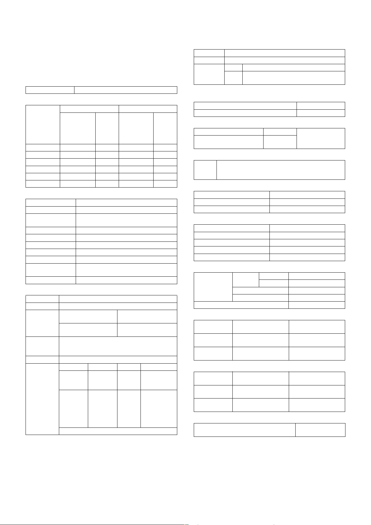
1. Product features
No. Feature Content Employed technology
1 Compact, lightweight, A3
tandem engine
High speed output Color: 26PPM
2 High-speed, first color copy Color: 8.0sec (A4/LT, without pre-scan, side paper exit)
3 Automatic recognition of
document kind
4 Manual paper feed capacity 300 sheets/64g (17 lbs.) Development of a large capacity manual feed
Heavy paper support 64 to 300g/m
Heavy paper duplex feed
support
5 Improved user maintenance Paper jam process: 2 positions of open/close (sides) Paper jam control technology
6 Improved service
maintenance
AR-C260: 670 x 676 x 709 mm (26.4 x 26.6 x 27.9 inch),
about 67kg (about 148 lbs.) (Include OC)
AR-C260M: 670 x 676 x 709mm (26.4 x 26.6 x 27.9 inch),
about 69kg (about 152 lbs.) (Include OC)
B/W: 33PPM (A4) / 32PPM (LT)
B/W: 7.0sec
The document kind is automatically recognized from the
document components by pre-scanning. (Photo, Print, Text,
Photo/Text, and Print/Text are supported.)
2
(17 to 80 lbs.) Oil-less fusing unit, paper feed/paper
64 to 200g/m
Toner supply: Cartridge replacement Mono-component wax-free toner
Developing section: Mono-component development
eliminates the need for developer replacement.
Drum section: Cartridge replacement Designed for easy maintenance
Fusing section: Simplified structure by wax-free. The unit can
be disassembled simply by releasing the lock with the knob.
Transfer section: One-touch extraction. Designed for easy
belt replacement.
Color resist automatic adjustment:
Visual judgment by paper exit is automatically performed.
2
(17 to 53 lbs.)
Mono-component wax-free toner, LED
printhead
LED printhead
Sharp’s unique technology of automatic
recognition of document kind, image process
technology
tray
transport technology
Mono-component wax-free toner
Mono-component wax-free toner. Designed
for easy maintenance
Designed for easy maintenance
Process control technology, which allows
user adjustment.
2. Newly employed technology
Item Content Remark
1 LED printhead employed • Employment of the 4bit LED provides
16-gradation expressions for each of YMCK.
• Free from mechanical noises which are produced
from the unit such as an LSU. Printing is started
immediately without waiting for stabilization of
the polygon motor speed.
• Lower power consumption than an LSU
2 Oil-less fusing system employed • Development of a new wax-free toner
• The wax-free fusing system provides a simplified
structure and improved paper feed capability.
• Notes and remarks can be put on a copy image
similar to normal page.
Resolution: 600dpi (Total dots: 7,424 dots)
AR-C260/C260M OUTLINE 1 - 1
Page 4
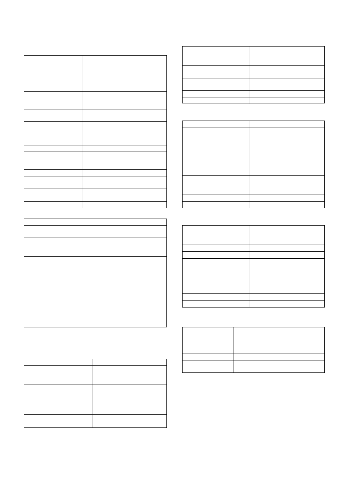
[2] CONFIGURATION
1. Product Line and options
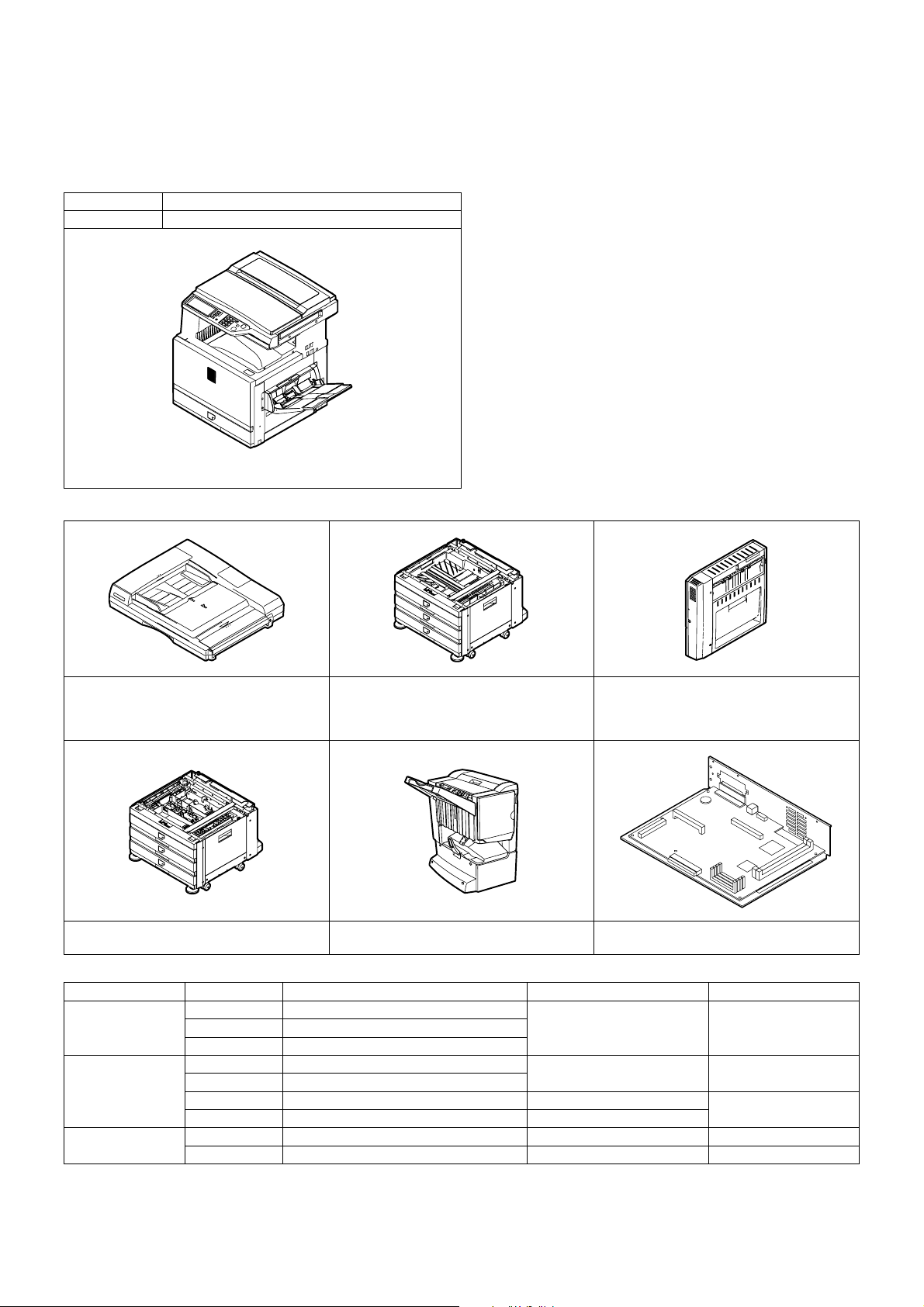
A. Line of machines
Model name Composition
AR-C260/260M Copier model/Printer model
AR-C260/260M
B. Line of options
AR-D18/Paper feed module
AR-RF3/Reversing automatic document feeder
AR-D19/Duplex module + Paper feed module
(2-stage) (Requires (AR-RB1).)
(3-stage paper feed desk)
AR-D17/Paper feed module
(1-stage paper feed desk) (Outside Japan only)
AR-F13/Saddle stitch finisher
(Requires (AR-RB1).)
AR-RB1/Duplex pass + Reverse unit
(Requires (AR-D19).)
AR-P16/Printer controller
(for AR-C260)
Line of other options
Model Name Necessary option Support model
Paper exit system AR-PN1A Punch unit (2-hole) AR-F13/Saddle stitch finisher
AR-PN1BA Punch unit (3-hole) (Outside Japan only)
AR-SC2 Staple cartridge
Printer system AR-NC5J Print server card (NIC) AR-P16/Printer controller AR-C260
AR-HD4 HDD
AR-NS2 Network scanner expansion kit
AR-U11, U15 Sharp desk license kit
Other AR-VR4 Original cover (Except Asia only)
AR-TE3 Paper exit tray (Except Asia only)
AR-C260/C260M CONFIGURATION 2 - 1
Page 5
C. Combination of options
Paper feed
AR-D17 1-stage paper feed desk
system
AR-D18 3-stage paper feed desk
AR-D19 2-stage duplex paper feed desk Reverse bypass module (AR-RB1) —
AR-RB1 Reverse bypass module Desk (AR-D19 only) —
AR-LC5 Large capacity tray Desk (Either of AR-D17/D18/D19) — Outside Japan only
Paper exit
AR-F13 Saddle finisher Desk (AR-D19) and Reverse bypass
system
AR-PN1A
AR-PN1BA
AR-S11 Sorter Desk (AR-D19) and Reverse bypass
Electrical
system
AR-NC5J NIC Printer controller (AR-P16) —
AR-HD4 HDD 3.5 inch (40GB) Printer controller (AR-P16) —
AR-NS2 Network scanner expansion kit Printer controller (AR-P16) The MFP model has the
• Expansion memory
Manufacture Capacity DIMM model number
Kingston Technology 128MB KVR133X64C3/128
Simple Technology 128MB RB 168S64-128A
Viking Compnehts 128MB VIK6642CL2
Memory Card Technology 128MB DM1665VS65804X-7G
The following combinations are also inhibited.
• OC cover and Duplex automatic document feeder
• Paper feed module (1-stage desk)/Paper feed module (3-stage desk)/Revere bypass module + Paper feed module (2-stage) (Only one of them can
be installed.)
Option name Necessary option Installing condition Remark
—
—
Cannot use the 3-stage paper
feed desk.
Cannot use the 1-stage paper
feed desk.
Cannot use the sorter.
module (AR-RB1)
Punch unit Saddle finisher (AR-F13)
module (AR-RB1)
Cannot use the saddle
finisher.
—
Added in running
change
128MB expansion memory — — Installed to the ICU
256MB expansion memory
——
(built in the machine) or
the printer controller.
(Use a commercially
available product.)
printer controller installed.
256MB KVR 1 33X64C3-256
256MB RB 168S64-256A
256MB VIK2642CL2
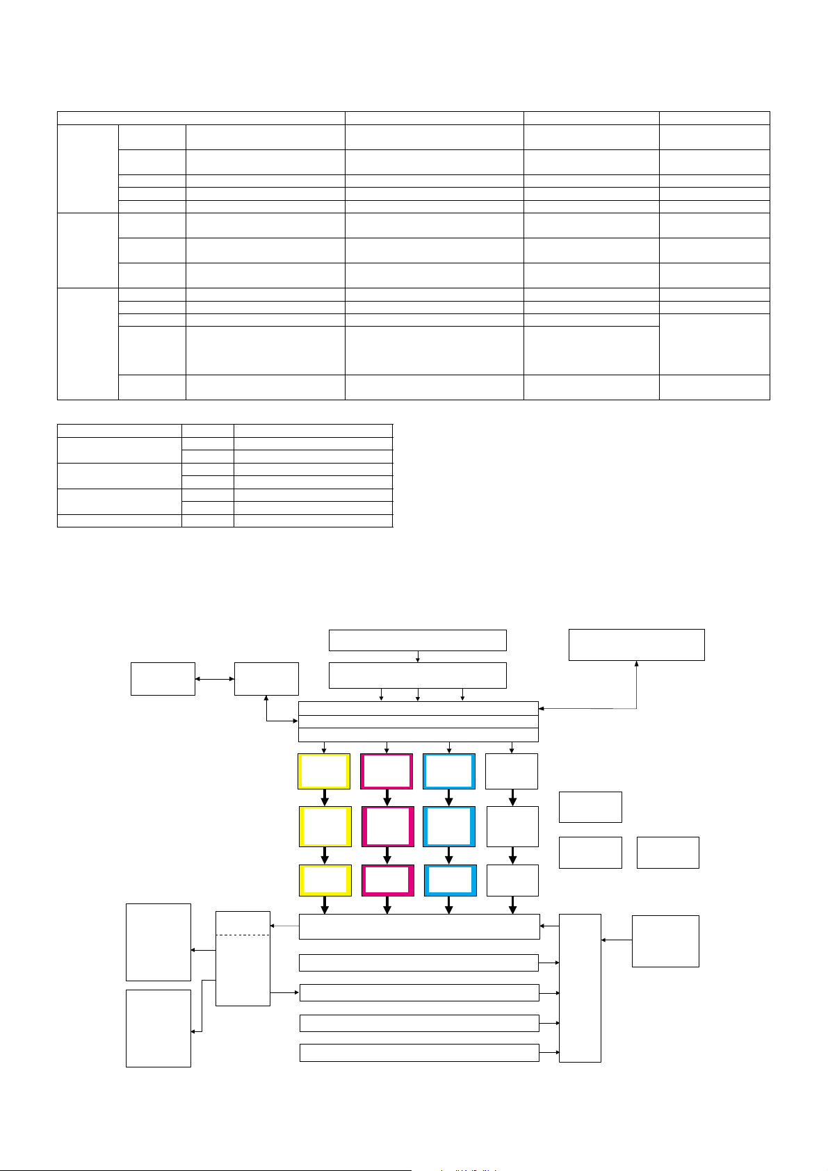
2. Block diagram
PC
Finisher
(Option)
Printer
controller
(Option)
Fusing/paper
exit section
Reverse
bypass
module
(Option)
LED head
(writing)
section
(Y)
Photo-
conductor
section
(Y)
Developing
section
(Y)
RADF unit (Option)
Image scanning (writing) section
(CCD PWB)
Image process section (MFP PWB)
Image process section 2 (ICU PWB)
Page memory
LED head
(writing)
section
(M)
Photo-
conductor
section
(M)
Developing
section
(M)
Transfer section
Paper feed tray section 1
Duplex section (Option)
LED head
(writing)
section
(C)
Photo-
conductor
section
(C)
Developing
section
(C)
LED head
(writing)
section
(K)
Photo-
conductor
section
(K)
Developing
section
(K)
PCU PWB
DC power unit
Paper
transport
section
Operation section
AC power unit
Large capacity
paper feed tray
unit (Option)
Outside Japan
only
Sorter
Paper feed tray section 2 (Option)
Paper tray section 3 (Option)
AR-C260/C260M CONFIGURATION 2 - 2
Page 6
[3] SPECIFICATIONS
1. Basic specifications
A. Base engine
(1) Type
Type Desk-top
(2) Engine speed
Color B/W
Print
Paper size
A4 26 ppm 26 cpm 33 ppm 33 cpm
8.5" x 11" 26 ppm 26 cpm 32 ppm 32 cpm
A5/8.5" x 5.5" 26 ppm 26 cpm 33 ppm 33 cpm
B5 26 ppm 26 cpm 33 ppm 33 cpm
B4/8.5" x 14" 15 ppm 15 cpm 17 ppm 17 cpm
A3/11" x 17" 13 ppm 13 cpm 15 ppm 15 cpm
B/W 4bit
mode
(Image quality
priority mode)
Copy
(3) Engine composition
Photoconductor kind OPC (Drum diameter:
Recording system Electronic photo system (LED head system)
Developing system Contact, non-magnetic 1-component
Charging system Saw teeth scorotron corona charging
Transfer system Transfer belt structure direct transfer system
Cleaning system Counter blade cleaning system
Fusing system Pressure roller fusing system
Oil supply Oil-less system
Waste toner process Self collection of each toner cartridge
Shifter Standard
development
Waste toner box collection for transfer belt
(4) Shifter
Type Shifter
Paper weight 64 to 105g/m
Paper size Non offset mode (Simple
load) 64 to 200g/m
Offset mode
64 to 200g/m
Productivity Non offset mode: Color 26 sheets,
Offset mode: Color/B/W 24 sheets
Offset width 30mm
Alignment Extending FR shift Between jobs
Non offset
mode
Offset
mode
∗ When A4/Letter recommended paper is used.
2
, 106 to 200g/m
2
2
B/W 32 sheets (LT)/33 sheets (A4)
Must not
fall from
the tray.
Within
50mm
Print
B/W 1bit
mode only
(Speed
priority mode)
φ30mm x 4)
2
A3W to A5, Postcard,
12" x 18" to 8.5" x 5.5"
A3 to A5
11" x 17" to 8.5" x 5.5"
——
Within
± 10mm
Copy
1 – 150
sheets:
10mm or more
151 sheets or
more:
5mm or more
(5) Engine resolution
Resolution Writing: 600dpi x 600dpi
Smoothing None
Gradation Color Writing: 1 pixel 16 gradations for each color
B/W Writing: 1 pixel 2 gradations (1bit)
∗ Dither matrix allows printing in 1-pixel, 256-gradation (8bit).
16 gradations (4bit)
(6) Warm-up
Warm-up time 99sec
Pre-heat function Yes
(7) Jam recovery time
With the left cover open About 60sec 60sec left
With the right and front covers
open
About 8sec
standard condition
(8) Image chip (Printable area)
Full size Total circumference 4mm ± 2mm
Only when A3 full image is outputted, 6mm or less in total.
CHP1 mode: 10mm or less at lead/rear edges
(9) Power source
Voltage 100V / 120V
Frequency 50/60Hz
Power cord Inlet type
(10) Power consumption
Max. power consumption 1450W
Stand-by (average) 180W
Low power mode 90Wh
Sleep mode 15Wh or less
Energy consumption efficiency 257Wh/h
(11) Noise/Ozone
Noise Operating B/W 68dB or less
Color 63dB or less
Stand-by 55dB or less
Sleep 40dB or less
Ozone 0.02g/m
3
or less
(12) External dimensions
Floor to Glass
surface
Floor to OC top
surface
Copier
(without desk)
670 x 676 x 655mm
(26.4 x 26.6 x 25.8 inch)
670 x 676 x 709mm
(26.4 x 26.6 x 27.9 inch)
Copier
(with 3-stage desk)
670 x 676 x 1049mm
(26.4 x 26.6 x 41.3 inch)
670 x 676 x 1104mm
(26.4 x 26.6 x 43.5 inch)
(13) Weight
Toner cartridge
Not installed About 85kg
Installed About 95kg
Copier
(without desk)
(About 187 lbs.)
(About 209 lbs.)
Copier
(with 3-stage desk)
About 114.5kg
(About 252 lbs.)
About 124.5kg
(About 274 lbs.)
(14) Machine occupying dimensions
Machine occupying dimensions
(Machine only, with the trays full open)
994 x 676mm
(39.1 x 26.6 inch)
∗
AR-C260/C260M SPECIFICATIONS 3 - 1
Page 7
B. Paper feed unit
(1) Machine paper feed tray
Paper feed system 1-stage tray
Paper feed size AB series: A3, B4, A4, A4R, B5, B5R,
A5, Special paper
Inch series: 11" x 17", 8.5" x 14",
8.5" x 13", 8.5" x 11", 8.5" x 11"R,
8.5" x 5.5", A4, EXTRA
Paper feed capacity 550 sheets (64g/m
500 sheets (80g/m
2
(17 lbs.) paper)
2
(21 lbs.) paper,
recommended paper for color)
2
Weight of paper suitable
64 to 105g/m
(17 to 28 lbs)
for paper feed
Paper kind Normal paper (including recommended
paper for color), recycled paper, printed
paper, punched paper, color paper,
letter head
Paper size detection Slide lever detection
Paper size selection Use selection
(Special paper size is inputted from the
operation panel.)
Heater Yes (Japan Only)
Remaining quantity
Yes (0, 25%, 50%, 75%, Full, 5 steps)
detection
Initial size when shipping A3 (11" x 17")
Tray attach/detach Possible
Universal support Universal tray (free size)
(2) Manual feed tray (Bypass tray)
Transport reference Center reference
Paper feed capacity 250 sheets (80g/m
100 sheets (Postcard)
Paper size A3W to A6R (Postcard)
Paper weight 64 to 300g/m
color
Paper kind Normal paper (including recommended paper
for color), OHP1, OHP2. heavy paper 1 (106
to 200g/m
(201 to 300g/m
Paper size detection Inch series: 12" x 18", 11" x 17", 8.5" x 14",
8.5" x 11", 8.5" x 11"R, 7.25" x 10.5"R,
8.5" x 5.5", A3, B4, A4, B5, A6R
AB series: A3W, A3, B4, A4, A4R, B5, A5,
A6R, 11" x 17", 8.5" x 14", 8.5" x 11",
7.25" x 10.5"R
Manual feed size
setup
Yes (Ignoring automatic setup)
Selected with key operation.
Detection of 8.5 x 14 can be changed to detection of 8.5 x 13 (216 x
330) with the simulation.
2
), 300 sheets (64g/m2),
2
/ 17 to 80lbs specified paper for
2
(28 to 53 lbs.)), heavy paper 2
2
(54 to 80 lbs.)), envelope
C. Paper exit unit
(1) Face down paper exit tray (Top section)
Paper exit position/system Machine top face down paper exit
Paper exit capacity 500 sheets (A4/LT recommended
Paper size A6R (Postcard), 8.5 x 5.5 to A3W
Paper weight 64 to 200g/m
Paper kind Normal paper (including
Remaining quantity detection No
Discharged paper full detection Yes
paper for color)
2
(17 to 53 lbs.)
recommended paper for color),
heavy paper 1 (106 to 200g/m
(28 to 53 lbs.))
2
(2) Face up paper exit tray (sides)
Paper exit position/system Machine side face up paper exit
Paper exit capacity 250 sheets (A4/LT recommended
paper for color)
Paper size All sizes which are fed
Paper weight 64 to 300g/m
2
(17 to 80 lbs.)
Paper kind All sizes which are fed (except for
OHP sheets)
Remaining quantity detection No
Discharged paper full detection Yes
(3) Face down paper exit tray (side)
(With the reverse unit installed)
Paper exit position/system Machine side face down paper exit
Paper exit capacity 250 sheets (A4/LT recommended
paper for color)
Paper size AB series: A3W, A3, B4, A4, A4R,
B5, B5R, A5
Inch series: 12" x 18", 11" x 17",
8.5" x 14", 8.5" x 11", 8.5" x 11"R,
7.25" x 10.5"R, 8.5" x 5.5", A3, B4,
A4, B5
2
Paper weight 64 to 200g/m
(17 to 53 lbs.)
Paper kind Normal paper (including
recommended paper for color)
Remaining quantity detection No
Discharged paper full detection Yes
(4) Face up paper exit tray (side)
(With the reverse unit installed)
Paper exit position/system Machine side face up paper exit
Paper exit capacity 250 sheets (A4/LT recommended
paper for color)
Paper size A3W to A5R (Postcard)
Paper weight 64 to 300g/m
2
(17 to 80 lbs.)
Paper kind Normal paper (including
recommended paper for color),
OHP, heavy paper (106 to
2
300g/m
(28 to 80 lbs.)), all other
paper which is supported by the
machine.
Remaining quantity detection No
Discharged paper full detection Yes
D. Scanner section
(1) Resolution, gradation
Scan resolution (dpi) 600 x 600dpi
Scan speed Color 16opm / B/W 19opm: A4/LT size
Scan gradation 256 gradations for each color
Exposure lamp Xenon lamp without electrode tube
Output gradation 8bit for each color
2 gradations for scanner B/W mode only
1bit for Scanner B/W mode only
AR-C260/C260M SPECIFICATIONS 3 - 2
Page 8
(2) Document table
Scan range (A3/WLT full image scan)
Document reference
Center reference
position
Detection Yes
Detection size Automatic detection
Inch
series
<INCH-1: Default>
11" x 17", 8.5" x 14", 8.5" x
11", 8.5" x 11"R, 5.5" x 8.5"
<INCH-2>
11" x 17", 8.5" x 13", 8.5" x
11", 8.5" x 11"R, 5.5" x 8.5"
AB series <AB-1: Default>
A3, B4, A4, A4R, B5, B5R, A5
<AB-2>
A3, 8.5" x 13" (216 x 330),
A4, A4R, B5, B5R, A5
Manual
Yes
doc size
selection
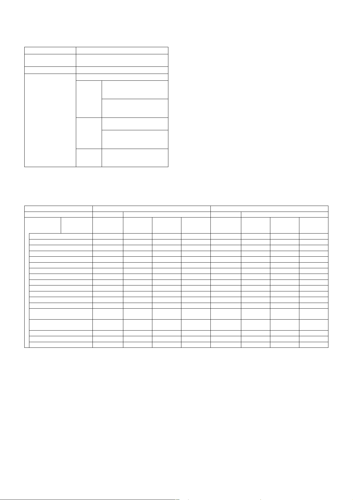
2. Functional specifications
A. Specifications of copy functions
(1) Copy speed (Continuous copy speed)
Color / B/W Color B/W
Print/Copy Print Copy Print Copy
Paper size
A3W (12
" x 18") 7 ppm 7 cpm 7 cpm 7 cpm 7 ppm 7 cpm 7 cpm 7 cpm
A3 (11
" x 17"), 8K 13 ppm 13 cpm 13 cpm 13 cpm 15 ppm 15 cpm 15 cpm 15 cpm
B4 (8.5
" x 14" / 8.5" x 13") 15 ppm 15 cpm 15 cpm 15 cpm 17 ppm 17 cpm 17 cpm 17 cpm
A4 26 ppm 26 cpm 26 cpm 26 cpm 33 ppm 33 cpm 33 cpm 33 cpm
8.5
" x 11" 26 ppm 26 cpm 26 cpm 26 cpm 32 ppm 32 cpm 32 cpm 32 cpm
A4R (8.5
" x 11"R) 19 ppm 19 cpm 19 cpm 19 cpm 22 ppm 22 cpm 22 cpm 22 cpm
B5, 16K 26 ppm 26 cpm 26 cpm 26 cpm 33 ppm 33 cpm 33 cpm 33 cpm
B5R (7.25
A5 (8.5
" x 5.5") 26 ppm 26 cpm 26 cpm 26 cpm 33 ppm 33 cpm 33 cpm 33 cpm
A6R (Postcard) 6 ppm 6 cpm 6 cpm 6 cpm 6 ppm 6 cpm 6 cpm 6 cpm
A6R (Normal paper) 13 ppm 13 cpm 13 cpm 13 cpm 15 ppm 15 cpm 15 cpm 15 cpm
OHP (Speed *2), A4 (LT) 26 ppm 26 cpm 26 cpm 26 cpm 26 ppm 26 cpm 26 cpm 26 cpm
OHP (Image quality), A4 (LT) 13 ppm 13 cpm 13 cpm 13 cpm 13 ppm 13 cpm 13 cpm 13 cpm
Heavy paper 1 (106 to 200g/m
A4 (LT) or less
Heavy paper 2 (201 to 300g/m
A4 (LT) or less
Envelope *1 (All kinds) 7 ppm 7 cpm 7 cpm 7 cpm 7 ppm 7 cpm 7 cpm 7 cpm
Size specified, EXTRA 7 ppm 7 cpm 7 cpm 7 cpm 7 ppm 7 cpm 7 cpm 7 cpm
Size not specified, EXTRA 7 ppm 7 cpm 7 cpm 7 cpm 7 ppm 7 cpm 7 cpm 7 cpm
∗ ppm: page per minute when printing two or more pages of a same document.
Magnification
ratio
" x 10.5"R), 16KR 19 ppm 19 cpm 19 cpm 19 cpm 22 ppm 22 cpm 22 cpm 22 cpm
cpm: copy per minute in 1-scan multi copy mode
* 1: Envelope kind: COM10, Monarch, DL, C5, Long No.3, Western type No. 2, Western type No. 4
* 2: Max. speed
* 3: Same as color print in the image quality priority mode (B/W 4bit)
B/W 4bit
(Image priority
mode)
2
),
13 ppm 13 cpm 13 cpm 13 cpm 13 ppm 13 cpm 13 cpm 13 cpm
2
),
13 ppm 13 cpm 13 cpm 13 cpm 13 ppm 13 cpm 13 cpm 13 cpm
Reduction
(25%)
Normal
(100%)
Enlargement
(400%)
B/W 1bit
(Speed priority
mode) *3
Reduction
(25%)
Normal
(100%)
Enlargement
(400%)
AR-C260/C260M SPECIFICATIONS 3 - 3
Page 9
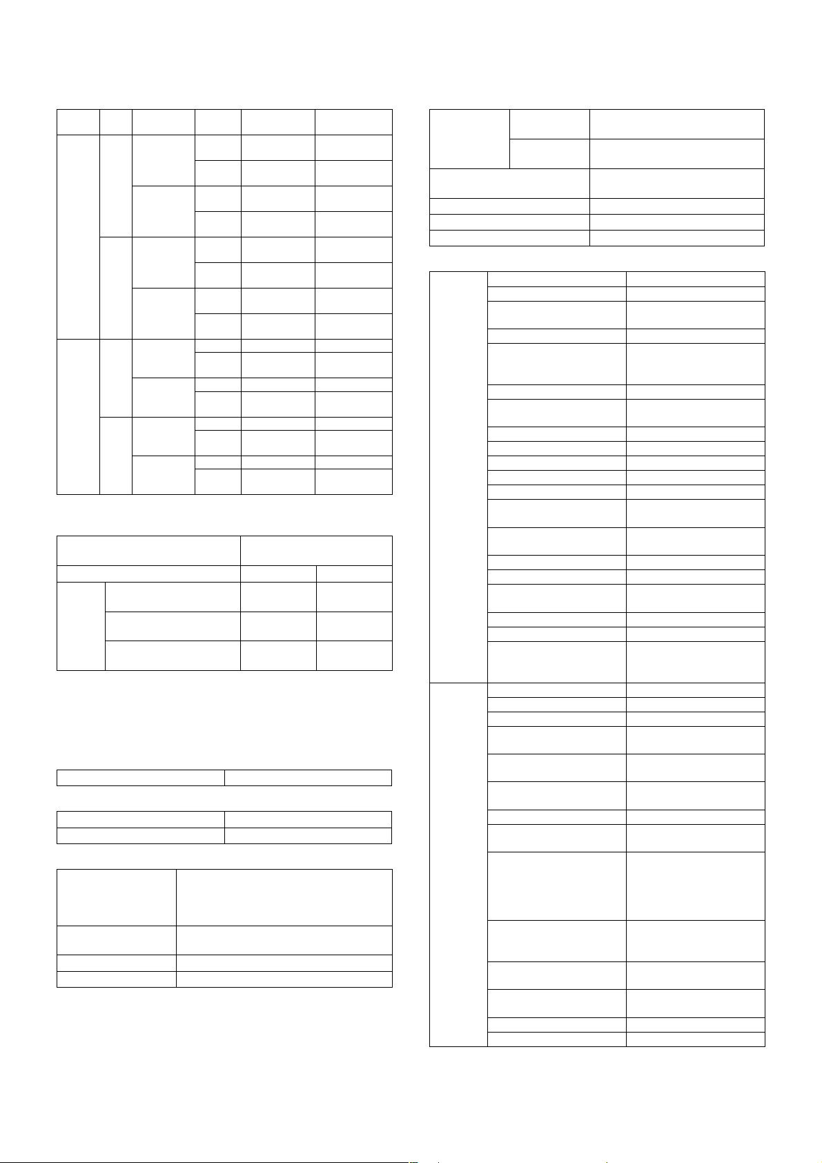
(2) First copy time
Platen/
Platen No Side face up No Within 7.0sec
RADF No Side face up No 8.0sec 9.5sec
* When the RADF is used, the data are those without APS.
Pre-
RADF
Paper exit
scan
position
Machine
face down
Yes Side face up No
Machine
face down
Machine
face down
Yes Side face up No — 12.2sec
Machine
face down
Rotation
copy
(A4/LT)
Yes Within 8.9sec
(A4)
No Within 8.8sec
(A4/LT)
Yes Within 10.7sec
(A4/LT)
Yes
No
Yes
Yes Within 10.4sec
(A4)
No 9.8sec 11.7sec
Yes Within 12.1sec
(A4/LT)
Yes
No — 14.4sec
Yes
B/W Color
Within 8.0sec
(A4/LT)
Within 10.7sec
(A4)
Within 10.2sec
(A4/LT)
Within 12.6sec
(A4/LT)
—
—
—
—
—
—
Within 10.9sec
(A4/LT)
Within 14.3sec
(A4)
Within 12.9sec
(A4/LT)
Within 16.3sec
(A4/LT)
Within 12.3sec
(A4)
Within 14.0sec
(A4/LT)
Within 15.7sec
(A4)
Within 17.6sec
(A4/LT)
(3) Job speed
Controller
B/W / Color B/W Color
Copy
method
10 x 1 set
S to S
10 x 5 sets
S to D
5 x 5 sets
D to D
(A4)
(Letter)
(A4)
(Letter)
(A4)
(Letter)
Copy conditions: Document size A4 (8.5" x 11"), transfer belt position:
B/W position, excluding pre-scan
Note: The above are speeds of copying a single document excluding
the pre-rotation and after-rotation of the process and paper cycle
time.
128MB+256MB
ICU: 256MB
19 cpm 16 cpm
33 cpm
26 cpm
32 cpm
33 cpm
26 cpm
32 cpm
(4) Continuous copy
Multi max. number 999 sheets
(5) Resolution
Scan resolution 600 x 600dpi
Writing resolution 600 x 600dpi
(6) Copy magnification ratio
Copy magnification
ratio
Custom magnification
ratio registration
Zoom 25%, 45 to 400% (1% increment)
Independent zoom Yes (25, 45 to 400%)
AB series: 25%, 50%, 70%, 81%, 86%,
100%, 115%, 122%, 141%, 200%, 400%
Inch series: 25%, 50%, 64%, 77%, 95%,
100%, 121%, 129%, 200%, 400%
AB series/Inch series: 4 keys (2E/2R)
(7) Density, copy image process
Exposure
mode
Color enhancement Yes (Valid for Text, Text/Print,
Manual steps 9 steps
Smoothing process No
Toner save mode Yes (for B/W)
Color
Auto: Auto, Pre-scan allowed
(Hexadecimal)
B/W (Binary) Auto: Text Auto: AE, Pre-scan
inhibited
Text/Photo, Print, Photo, Map)
(8) Copy functions
Functions APS Yes
AMS Yes
Special
functions
ACS
(Auto Color Selection)
Paper type select Yes
Free size input Document: Yes
Auto tray switching Yes
Rotation copy Yes (A4/8.5 x 11/B5/16K
Rotation sort No
Electronic sort (E-RDH) Yes (B/W only)
Copy reservation No
Program call/registration Yes (Max. 9 items)
Proof copy No
Pre-heat Yes (Conditions are set by
Auto power shut off Yes (Conditions are set by
Department management Yes (200 departments)
Key operator program Yes
Communication support
(RIC)
Process control Yes
Card counter support Option (Japan only)
Con vendor support Yes (A connector must be
Binding margin Yes
Edge erase/Center erase Yes
1 set 2 copy Yes
Cover paper Yes (Color, one sheet
OHP insert paper Yes (White paper insertion
Insert paper insertion
(Index)
Centering Yes
Multi shot (N in 1) Yes (Ruled line ON/OFF
Center binding Option (B/W only)
Duplex copy direction
switch
Negative/Positive
conversion
Photo repeat Yes (2/4/8/12/16/24)10 is
RGB adjustment Yes
Color balance Yes
No
Paper: Yes
(Manual feed cassette)
paper size only)
the key operation.)
the key operation.)
Yes (Requires Connector
or Installing port.)
installed inside the
machine.)
only)
only)
No
allowed)
∗ Requires Duplex desk,
Duplex pass/Inverter,
Saddle finisher (in
saddle stitch only).
Option
∗ Requires Duplex desk,
Duplex pass/Inverter.
No
for visiting cards.
AR-C260/C260M SPECIFICATIONS 3 - 4
Page 10
Special
functions
Color Gamma adjustment Yes
Brightness adjustment Yes
Contrast adjustment No
Sharpness adjustment Yes
Mirror image Yes
Single color 6 colors (R, G, B, C, M, Y)
Enlargement continuous
copy
Background erase Yes
A3 wide copy Yes
Auto color calibration Yes
Auto registration Yes
Yes
(9) Memory limitation matrix
Combination Standard Expansion 1 Expansion 2
Copier specifications
Copy Single Color to A4 (8.5" x 11") SOPM SOPM SOPM
Duplex Color to A4 (8.5" x 11") SOPM SOPM SOPM
B/W (Electronic sort): Equivalent to "TEST SHEET B."
SOPM: Scan Once Print (Copy) Many
ICU PWB
Mode Document size — — —
B/W to A4 (8.5" x 11") 400 surfaces 400 surfaces 680 surfaces
B/W to A4 (8.5" x 11") 400 surfaces 400 surfaces 680 surfaces
Standard (Slot 1) 256MB 256MB 256MB
Expansion memory (Slot 2) — 128MB 256MB
Total memory capacity 256MB 384MB 512MB
B4, A3 (8.5" x 14", 11" x 17") SOPM SOPM SOPM
A3W (12" x 18") SOPM SOPM SOPM
B4, A3 (8.5" x 14", 11" x 17") 200 surfaces 200 surfaces 340 surfaces
A3W (12" x 18") 165 surfaces 165 surfaces 280 surfaces
B4, A3 (8.5" x 14", 11" x 17") No SOPM SOPM
A3W (12" x 18") — — —
B4, A3 (8.5" x 14", 11" x 17") 200 surfaces 200 surfaces 340 surfaces
A3W (12" x 18") — — —
3. Environment conditions
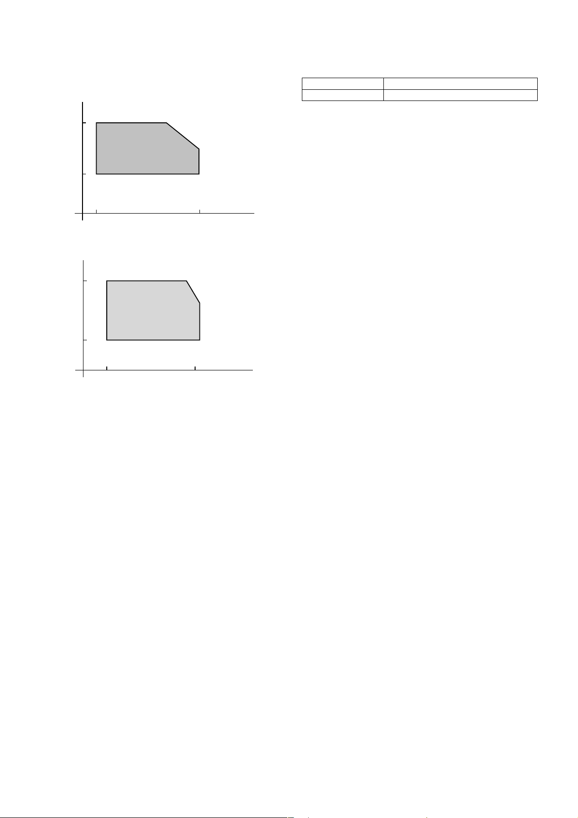
A. Operating environment conditions
(1) Temperature and humidity
Humidity
RH
80%
20%
15˚C (59˚F) 35˚C (95˚F)
Temperature
(2) Power voltage and frequency
Power voltage Specified voltage ±10%
Power frequency Specified frequency ±2%
30˚C (86˚F), 80%
35˚C (95˚F), 60%
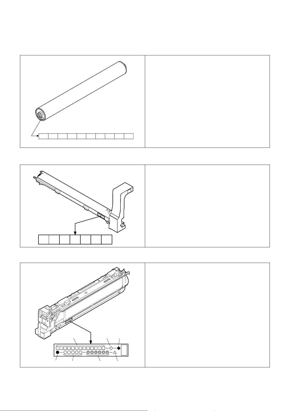
B. Storage environment conditions
Humidity
RH
90%
10%
Humidity
RH
90%
20%
–10˚C (14˚F) 50˚C (122˚F)
Consumable parts (Not unpacked)
Machine
40˚C (104˚F), 90%
Temperature
50˚C (122˚F), 60%
40˚C (104˚F), 90%
–5˚C (23˚F) 40˚C (104˚F)
AR-C260/C260M SPECIFICATIONS 3 - 5
Temperature
Page 11
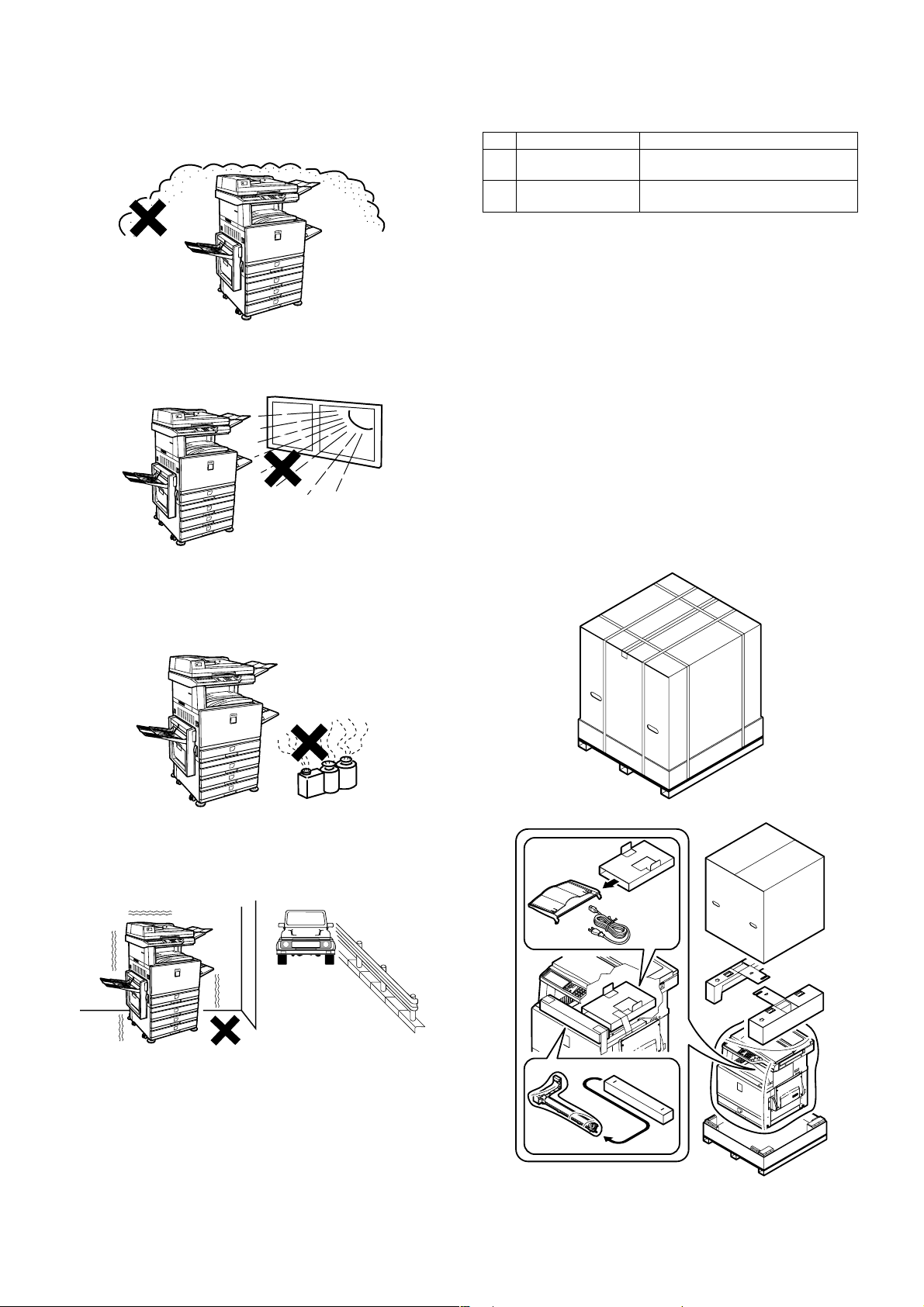
C. Transit environment conditions D. Standard temperature and humidity
Temperature 20 to 25°C (68 to 77°F)
Humidity 65 ±5%
Humidity
RH
90%
20%
Machine
30˚C (86˚F), 90%
45˚C (113˚F), 60%
Humidity
RH
90%
10%
–20˚C (4˚F) 45˚C (113˚F)
–5˚C (23˚F) 40˚C (104˚F)
Temperature
Consumable parts
30˚C (86˚F), 90%
45˚C (113˚F), 60%
Temperature
AR-C260/C260M SPECIFICATIONS 3 - 6
Page 12

[4] CONSUMABLE PARTS
1. Supply system table
A. USA/Canada
Part name Model name Content Life Packing Remark
1 Toner (Black) AR-C26TBU Toner cartridge (Black) x 1 16.7K (A4/LT 6%) 10 For A4/LT 5%,
2 Color toner (Cyan) AR-C26TCU Toner cartridge (Cyan) x 1 5.5K (A4/LT 10%) 10
3 Color toner (Magenta) AR-C26TMU Toner cartridge (Magenta) x 1 5.5K (A4/LT 10%) 10
4 Color toner (Yellow) AR-C26TYU Toner cartridge (Yellow) x 1 5.5K (A4/LT 10%) 10
5 Photoconductor drum
cartridge
6 Drum AR-C26DR OPC Drum x 1 50K 10
7 Main charger kit AR-C26MK Charging unit x 1 50K 10
AR-C26DU Drum cartridge (including OPC drum & unit
parts)
Color identification seal (Y/M/C/K) x 1 each
Cleaning blade x 1
Toner reception seal x 1
x 1 50K 10
B. Europe/Australia
Part name Model name Content Life Packing Remark
1 Toner (Black) AR-C26TBE Toner cartridge (Black) x 1 16.7K (A4/LT 6%) 10 For A4/LT 5%,
2 Color toner (Cyan) AR-C26TCE Toner cartridge (Cyan) x 1 5.5K (A4/LT 10%) 10
3 Color toner (Magenta) AR-C26TME Toner cartridge (Magenta) x 1 5.5K (A4/LT 10%) 10
4 Color toner (Yellow) AR-C26TYE Toner cartridge (Yellow) x 1 5.5K (A4/LT 10%) 10
5 Photoconductor drum
cartridge
6 Drum AR-C26DM OPC Drum x 1 50K 10
7 Main charger kit AR-C26MKE Charging unit x 1 50K 10
AR-C26DUE Drum cartridge (including OPC drum & unit
parts)
Color identification seal (Y/M/C/K) x 1 each
Cleaning blade x 1
Toner reception seal x 1
x 1 50K 10
life is 20K.
life is 20K.
C. Central & South America
Part name Model name Content Life Packing Remark
1 Toner (Black) AR-C26TBA Toner cartridge (Black) x 1 16.7K (A4/LT 6%) 10 For A4/LT 5%,
2 Color toner (Cyan) AR-C26TCA Toner cartridge (Cyan) x 1 5.5K (A4/LT 10%) 10
3 Color toner (Magenta) AR-C26TMA Toner cartridge (Magenta) x 1 5.5K (A4/LT 10%) 10
4 Color toner (Yellow) AR-C26TYA Toner cartridge (Yellow) x 1 5.5K (A4/LT 10%) 10
5 Photoconductor drum
cartridge
6 Drum AR-C26DR OPC Drum x 1 50K 10
7 Main charger kit AR-C26MK Charging unit x 1 50K 10
AR-C26DU Drum cartridge (including OPC drum & unit
parts)
Color identification seal (Y/M/C/K) x 1 each
Cleaning blade x 1
Toner reception seal x 1
x 1 50K 10
life is 20K.
D. Philippine/Taiwan/SMEF
Part name Model name Content Life Packing Remark
1 Toner (Black) AR-C26TBP Toner cartridge (Black) x 1 16.7K (A4/LT 6%) 10 For A4/LT 5%,
2 Color toner (Cyan) AR-C26TCP Toner cartridge (Cyan) x 1 5.5K (A4/LT 10%) 10
3 Color toner (Magenta) AR-C26TMP Toner cartridge (Magenta) x 1 5.5K (A4/LT 10%) 10
4 Color toner (Yellow) AR-C26TYP Toner cartridge (Yellow) x 1 5.5K (A4/LT 10%) 10
5 Photoconductor drum
cartridge
6 Drum AR-C26DR OPC Drum x 1 50K 10
7 Main charger kit AR-C26MK Charging unit x 1 50K 10
AR-C26DU Drum cartridge (including OPC drum & unit
parts)
Color identification seal (Y/M/C/K) x 1 each
Cleaning blade x 1
Toner reception seal x 1
x 1 50K 10
life is 20K.
AR-C260/C260M CONSUMABLE PARTS 4 - 1
Page 13

E. SOCC parts
Part name Model name Content Life Packing Remark
1 Toner (Black) AR-C26TB-C Toner cartridge (Black) x 1 16.7K (A4/LT 6%) 10 For A4/LT 5%,
2 Color toner (Cyan) AR-C26TC-C Toner cartridge (Cyan) x 1 5.5K (A4/LT 10%) 10
3 Color toner (Magenta) AR-C26TM-C Toner cartridge (Magenta) x 1 5.5K (A4/LT 10%) 10
4 Color toner (Yellow) AR-C26TY-C Toner cartridge (Yellow) x 1 5.5K (A4/LT 10%) 10
5 Photoconductor drum
cartridge
6 Drum AR-C26DR-C OPC Drum x 1 50K 10
7 Main charger kit AR-C26MK-C Charging unit x 1 50K 10
AR-C26DU-C Drum cartridge (including OPC drum &
unit parts)
Color identification seal (Y/M/C/K) x 1 each
Cleaning blade x 1
Toner reception seal x 1
x 1 50K 10
life is 20K.
F. SRH parts
Part name Model name Content Life Packing Remark
1 Toner (Black) AR-C26TB-C Toner cartridge (Black) x 1 16.7K (A4/LT 6%) 10 For A4/LT 5%,
2 Color toner (Cyan) AR-C26TC-C Toner cartridge (Cyan) x 1 5.5K (A4/LT 10%) 10
3 Color toner (Magenta) AR-C26TM-C Toner cartridge (Magenta) x 1 5.5K (A4/LT 10%) 10
4 Color toner (Yellow) AR-C26TY-C Toner cartridge (Yellow) x 1 5.5K (A4/LT 10%) 10
5 Photoconductor drum
cartridge
6 Drum AR-C26DR-C OPC Drum x 1 50K 10
7 Main charger kit AR-C26MK-C Charging unit x 1 50K 10
AR-C26DU-C Drum cartridge (including OPC drum &
unit parts)
Color identification seal (Y/M/C/K) x 1 each
Cleaning blade x 1
Toner reception seal x 1
x 1 50K 10
life is 20K.
2. Consumables (kit, unit)
Part name Model name Content Life
1 Upper heat roller kit AR-C26UH Upper heat roller x 1 100K *1
Heat roller 60T gear x 1
Upper heat roller bearing x 2
Thermistor x 1
Upper heat roller stopper x 2
2 Lower heat roller kit AR-C26LH Lower heat roller x 1 100K *1
Lower heat roller bearing x 2
Thermistor x 1
Lower heat roller stopper x 2
Fusing separation pawl lower x 2
3 Transfer belt kit AR-C26TT Transfer belt x 1 100K *1
4 Transfer roller kit AR-C26TX Transfer roller x 4 100K
5 Transfer waste toner tank unit AR-C26HB Transfer waste toner tank unit x 1 100K
6 Filter kit AR-C26FL Ozone filter A x 1 50K
Ozone filter B x 1
7 Saddle staple cartridge AR-SC2 —
5 Fusing unit AR-C26FU (230V heater lamp)
AR-C26FU1 (120V heater lamp)
AR-C26FU2 (100V heater lamp)
6 Transfer belt unit AR-C26TU Transfer unit for servicing 100K *1
Fusing unit for servicing
(including upper/lower heater lamps)
*1
*1: Replace at 100K or within 2 years
AR-C260/C260M CONSUMABLE PARTS 4 - 2
Page 14
3. Photoconductor, developer, toner
A. Lot number identification and the term of validity
(1) Photoconductor
(1) (2) (3) (4) (5) (6) (7)(8)(9)
The term of validity: 36 months from the production day (month).
(2) Photoconductor cartridge
(10)
(1) Figure
2 for this model
(2) Alphabet
Indicates the model support code.
(3) Figure
Indicates the end digit of the production year.
(4) Figure or X, Y, Z
Indicates the production month. (X= October, Y= November,
Z= December)
(5) (6) Figure
Indicates the production day.
(7) Figure or X, Y, Z
Indicates the packing month. (X= October, Y= November,
Z= December)
(8) (9) Figure
Indicates the packing day.
(10) Figure or alphabet
Indicates the production division.
(1) Figure
Version No.
(2) Figure
The end digit of the year.
(3) Alphabet
Production code (B for SOCC)
(4) Alphabet
Destination code
(5) (6) Figure
Production day
(7) Figure or X, Y, Z
Indicates the production month. (X= October, Y= November,
Z= December)
(1) (2) (3) (4) (5) (6) (7)
The term of validity: 24 months from the production day (month).
(3) Toner cartridge
(1)
(4) (5) (6) (7)
The term of validity: 24 months from the production day (month).
(2) (3)
(1) Alphabet or figure
Unit code
(2) Alphabet
Destination code
(3) Alphabet
Skating
(4) Alphabet
Production site code
(5) Figure
Serial number (5 digits)
(6) Figure
Production year, month, day (6 digits)
(7) Alphabet
Version No. (A ~ sequentially revised)
AR-C260/C260M CONSUMABLE PARTS 4 - 3
Page 15

[5] UNPACKING AND INSTALLATION
1. Installing (use) conditions
Before installing the machine, check that the following installing (use)
conditions are satisfied.
If the installing (use) conditions are not satisfied, the machine may not
display full performances, resulting in troubles. It may also cause
safety problems. Therefore, be sure to arrange the installing (use) conditions before setting up the machine.
No. Content
1 Bringing space
2 Installing space
3 Power source (Capacity, fluctuation, safety)
4 Floor strength
5 Direct rays of the sun, dust, temperature, humidity, gases,
chemicals
A. Bringing space
For installation of a large size machine, be sure to check that the door
size is great enough before bringing in.
B. Installing space
The following space must be provided around the machine in order to
assure machine performances and proper operations.
If any option is installed, provide the additional space for installing it.
Especially the space at the rear of the machine must be provided sufficiently. If not, the machine cannot exhibit functions against heat and
dust, causing some troubles.
11.8"
(30cm)
31.5"
(80cm)
23.6"
(60cm)
(3) Power frequency, waveform
The frequency must be within the range of the specified frequency
±2%. If power waveform is deformed, a trouble may occur.
(4) Safety
Be sure to properly ground the machine.
(5) Power plug
Check the form of the power plug. If the shape does not match, do not
use it.
D. Floor strength and level
This machine is considerably heavy and becomes heavier with an
option installed.
The floor must be strong enough for assuring safety.
If not, color shift or image distortion may occur.
E. Direct rays of the sun, dust, temperature,
humidity, gasses, chemicals, vibration
(1) Temperature and humidity
This machine is designed to perform properly under the specified temperature and humidity. If the temperature and humidity exceeds the
specified range, the machine may not operate properly and or cause
equipment failure.
Especially when the humidity is too high, paper absorbs humidity to
cause a paper jam or dirty copy.
23.6"
(60cm)
C. Power source
(Capacity, voltage, frequency, safety, plug)
If the power specifications are not satisfied, the machine cannot exhibit
full performances and may cause safety trouble.
Strictly observe the following specifications.
(1) Power capacity
Check that the following power capacity is satisfied. If not, additionally
provide a power source.
Current capacity
Japan: 20A or more
100V: 15A or more
200V: 10A or more
(2) Power voltage
Measure the voltage during copying to check that the voltage is in the
range of the specified voltage ±10%.
If the voltage is outside the specified range, use thicker lead wires to
reduce impedance.
(An electrical work is required.)
Use of a step-up transformer is also available. In this case, the capacity must be great enough for the max. power consumption of the
machine.
(Do not install the machine near a stove, a humidifier, or an air conditioner.)
Do not install the machine near a heater, a cooler, or a humidifier.
Dew may be formed inside the machine to cause a trouble. Use
enough care for ventilation.
Humidity (RH)
80%
60%
20%
15˚C 30˚C 35˚C
Temperature
AR-C260/C260M UNPACKING AND INSTALLATION 5 - 1
Page 16
(2) Dust
If dust enters the machine, it may cause dirty copy and a paper jam,
resulting in a shortened lifetime.
(3) Direct rays of the sun
If the machine is installed under the rays of the sun, the exterior of the
machine may be discolored and abnormal copies may be produced.
(4) Gases and chemicals
Do not install the machine at a place where there are gases and chemicals. Especially be careful to avoid installation near a diazo-type
copier, which produces ammonium gas.
Copy quality may be adversely affected and a trouble may be caused.
2. Transit and delivery
No. Content Method
1 Implements, facility,
and man power
2 Delivery Transit must be made in packed
Use a forklift. (If no forklift is available,
manpower of four persons is required.)
condition.
A. Implements, facility, and manpower
It is recommendable to use a forklift for bringing in the machine for
safety.
If no forklift is available, man-power of four persons is required. The
machine is considerably heavy, and requires safety precautions for
delivery and installation.
Transit of the machine must be made in packed condition to the installing place.
B. Delivery
Remove the packing materials prior to installation in the ofice environment.
3. Unpacking
A. Unpacking procedure
1) Remove the PP band.
2) Remove the top case.
3) Remove the internal packing pads and the items packed together
with the machine.
4) Remove the machine from the package.
(5) Vibration
Avoid installation near a machine which produces vibrations.
If vibrations are applied to the copier machine, copy images may be
deflected and a trouble may be caused.
AR-C260/C260M UNPACKING AND INSTALLATION 5 - 2
Page 17
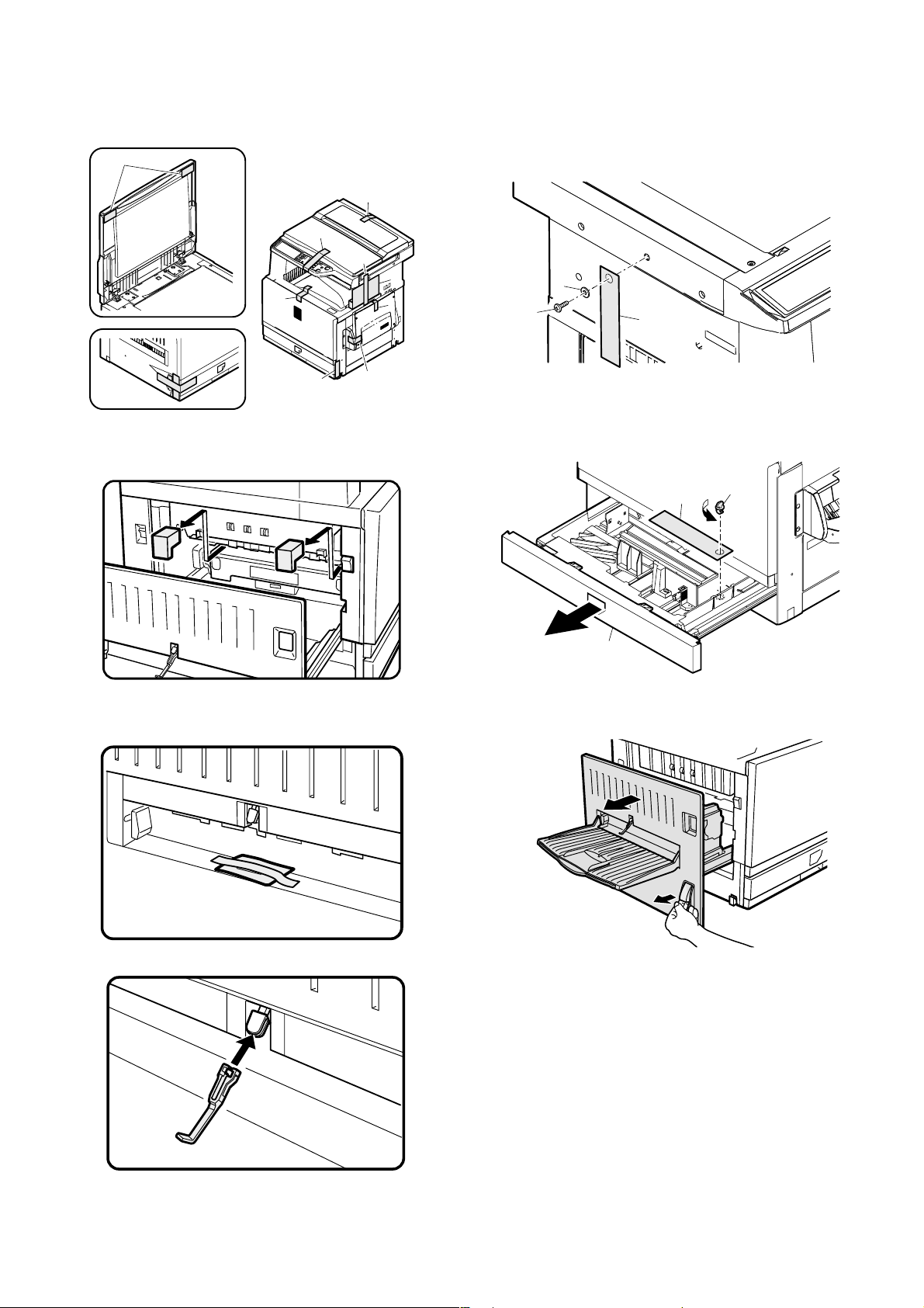
Fixing tape and protection pads removal
1) Remove the fixing tape and protection pads from the machine.
2
1
1
1
1
1
1
4. Lock release
A. Scanner (2/3 mirror unit) lock release
1) Remove the scanner fixing screw, and remove the caution label.
2
1
3
1
1
Note: The document cover may be supplied as a standard part in some
destinations, and may be an option in some other destinations.
2) Open the left door, and remove the transfer fixing pads.
1
Actuator installation
1) Remove the actuator fixed to the left door.
B. Main body cassette lock release
1) Pull out the main body cassette.
2) Remove the rotation plate fixing pad and remove the caution label.
3
1
2
C. Transfer unit pressure release
1) Pull the knob and open the left door.
2) Install the actuator to the paper exit port of the left door.
AR-C260/C260M UNPACKING AND INSTALLATION 5 - 3
Page 18
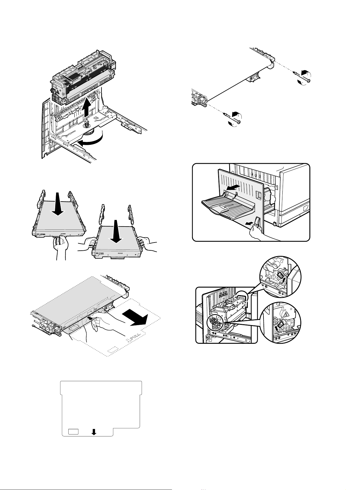
2) Loosen the roller knob (A), and remove the fusing unit (B).
B
6) Remove the screw and apply a tension to the transfer belt.
A
3) Hold section A of the transfer unit and pull it out so that the both
sides of the transfer unit can be held.
4) Hold sections B and remove the transfer unit.
B
A
5) Remove the transfer belt protect sheet.
7) Install the transfer unit to the machine.
5. Fusing heat roller pressing (F/R)
1) Pull the knob and open the left door.
2) Turn the pressure release lever to press.
Note: If the machine is left for one month or more, the heat roller rubber
may be deformed. In such a case, therefore, release the pressure.
PULL
AR-C260/C260M UNPACKING AND INSTALLATION 5 - 4
Page 19
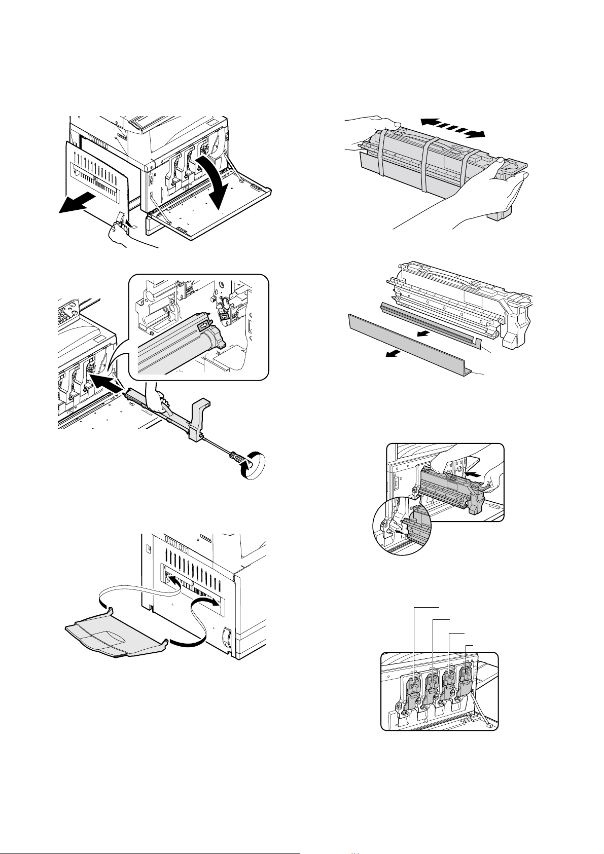
6. Black drum cartridge insertion
1) Pull the knob and open the left door.
2) Open the front cover.
8. Toner cartridges installation
1) Shake the toner cartridge horizontally several times.
2
3
1
3) Insert the black drum cartridge, and fix it with a screw.
2) Remove the tape, and remove the protection pad.
2
1
3) Open the front cover.
4) Insert the toner cartridge.
∗ As shown below, fit the cartridge with the insertion port and push
it in.
7. Paper exit tray installation
1) Install the paper exit tray to the left door.
Note: The paper exit tray may be supplied as a standard part in some
destinations, and may be an option in some other destinations.
AR-C260/C260M UNPACKING AND INSTALLATION 5 - 5
Note: Be sure to install the color cartridges to their proper positions.
Avoid instillation to a different color position.
[Color toner cartridge positions]
Yellow
Magenta
Cyan
Black
Page 20
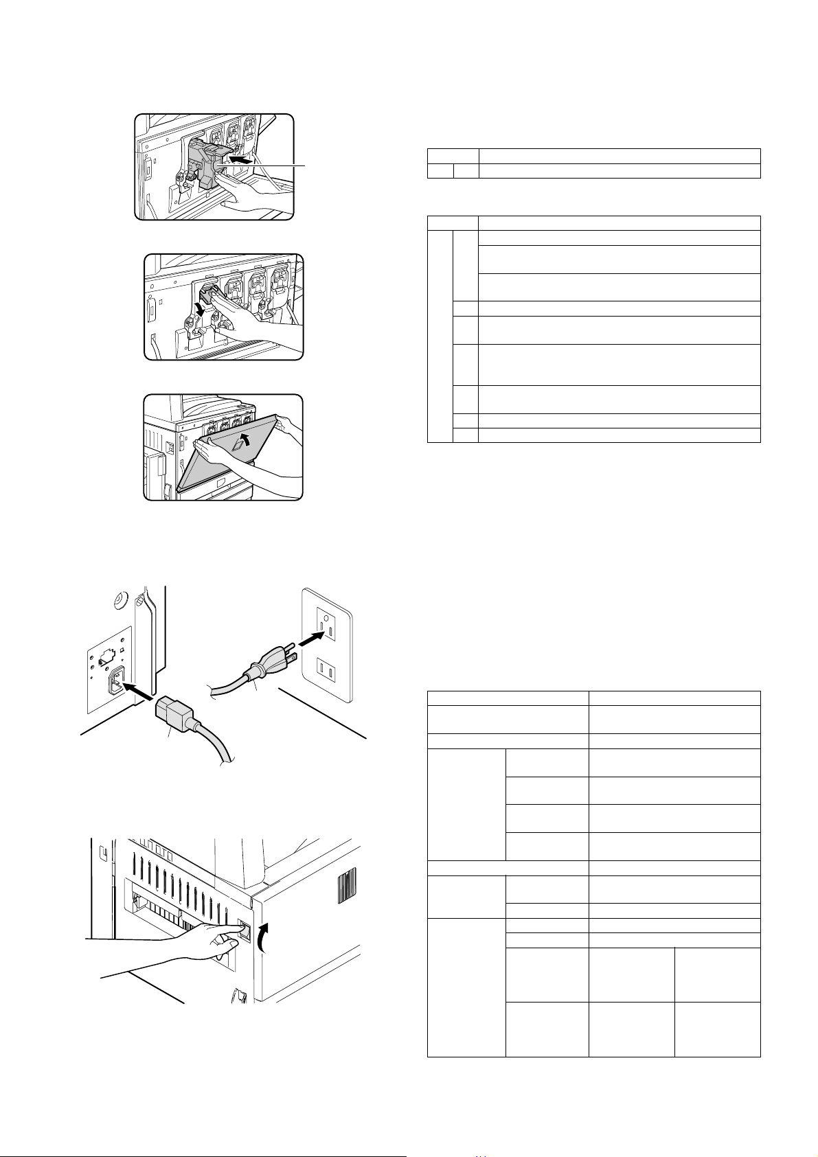
5) Insert the cartridge securely until it locks.
6) Return the cartridge lever to the original position.
7) Close the front cover.
Do not press
this section.
(If it is pressed,
the lock lever
falls.)
11. Specifications setup
Used to set the specifications with SIM26 according to the customer's
request.
SIM No Content
26 6 Used to set the destination.
To customize the following items after completion of the destination
setup, change the set values.
SIM No Content
26 2 Used to set the large capacity paper feed tray paper size.
Used to set the detection paper size and display when
using 8.5 x 13 size paper and document.
Used to set the paper kind and the display form in the
manual paper feed mode.
3 Used to set the auditor specification mode.
5 Used to set the count mode of the total counter and the
maintenance counter.
18 Used to set YES/NO of the toner save mode (Only in UK
and Japan versions) For other destination versions, this
setup is made by the user program.
52 Used to set YES/NO of counting when non-print paper is
passed through each counter.
53 Used to set YES/NO of user calibration permission.
65 Used to set the limit number of sheets for stapling.
On completion of the installation of the AR-F13 finisher, please change
the default output tray of the machine to the top tray of the finisher.
9. AC cord connection
1) Insert the AC power plug into the connector at the rear of the
machine, and connect the other end to the power outlet.
2
1
10. Machine power ON
1) Turn on the power switch on the left side of the machine.
12. Image quality check
Check the following items related to image quality. For details of the
adjustment and checking procedures, refer to the chapter of adjustments.
1) Image focus, image skew (Refer to ADJ 3.)
2) Image registration (Refer to ADJ 4.)
3) Image loss, void area (Refer to ADJ 10.)
4) Copy color balance, density (Refer to ADJ 11.)
Check that the above items are normal. If not, make the adjustment.
13. Function and operation check
Check that the following operations are normal.
Check item Installation
Key input operation (Operation
panel)
Display (Operation panel)
Paper feed
operation
Paper size detection operation
Document
size detection
operation
RADF
operation/
Duplex copy
operation
Manual paper
feed
Machine paper
tray
Desk unit
paper feed tray
Large capacity
paper feed tray
Document
table mode
RADF mode When the RADF is installed.
S-S mode When the RADF is installed.
D-S mode When the RADF is installed.
S-D mode When the
D-D mode When the
When the desk unit is installed.
When the large capacity paper
feed tray is installed.
RADF is
installed.
RADF is
installed.
When the desk
unit with the
duplex unit is
installed.
When the desk
unit with the
duplex unit is
installed.
AR-C260/C260M UNPACKING AND INSTALLATION 5 - 6
Page 21

Check item Installation
Bookbinding operation When the finisher is installed.
Stapling operation When the finisher is installed.
Grouping operation When the
finisher is
installed.
Sorting operation When the
finisher is
installed.
When the
sorter is
installed.
When the
sorter is
installed.
14. Setup and adjustment data recording
Print the various setup data and the adjustment data (list) with SIM226 and keep the data.
In case of a memory trouble, if the data are not kept, all the adjustments must be made again.
If the data are kept, the setup values and the adjustment values can be
entered without adjustments, shortening the servicing time.
15. Necessary works before moving the
machine
1) If the following options are installed, remove all of them from the
machine.
•Sorter
• Finisher
• Reverse unit
• RADF unit
• Desk unit
2) Remove the following consumable parts from the machine.
• Paper
• Toner cartridge
• Photoconductor cartridge
3) Lock the following sections.
• Scanner (Optical section)
• Paper cassette lift plate
AR-C260/C260M UNPACKING AND INSTALLATION 5 - 7
Page 22
[6] EXTERNAL VIEW AND INTERNAL STRUCTURE
1. Name and function of each section
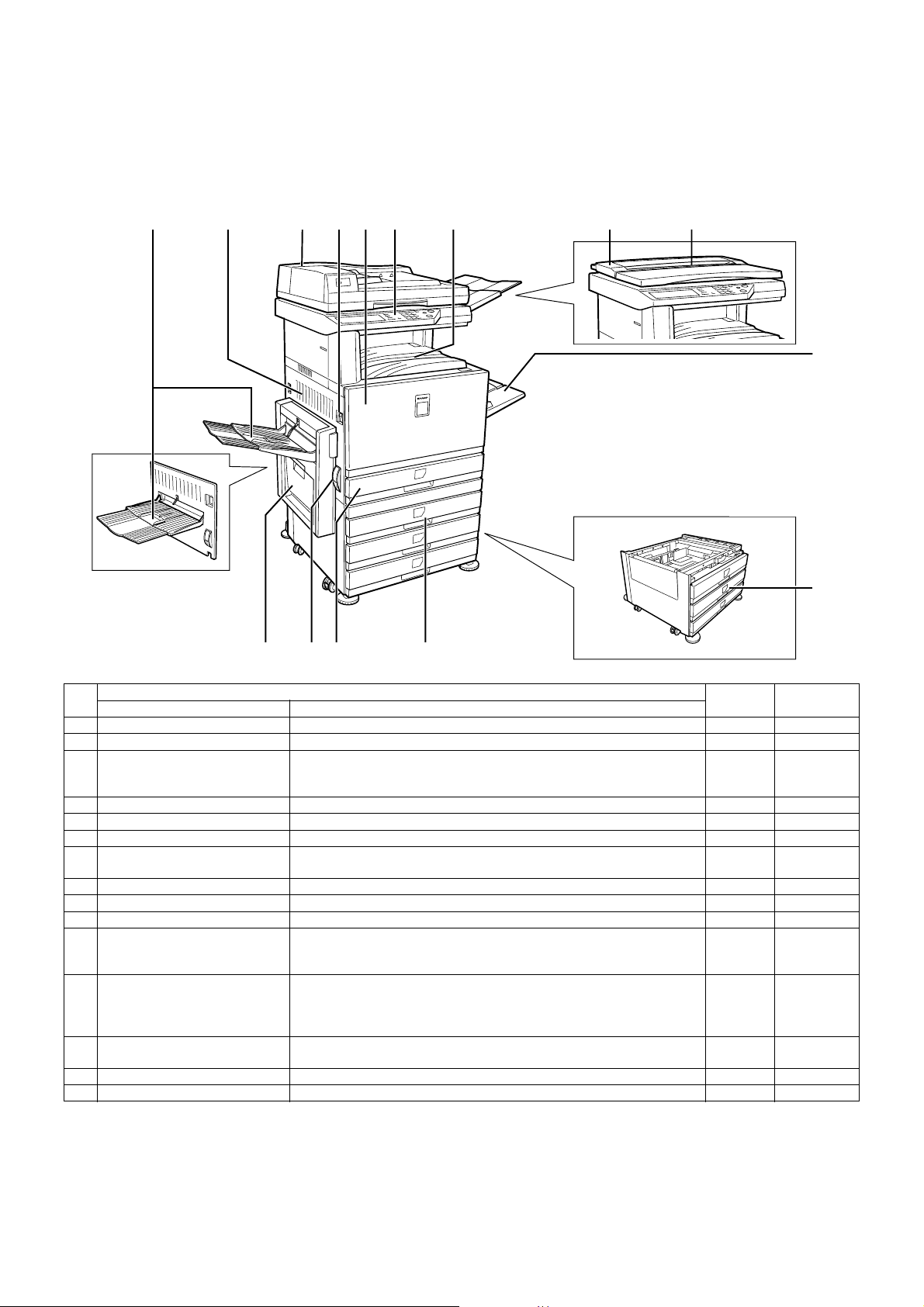
A. External view
1
When the reverse bypass
module (15) is not installed.
234567 8 9
10
11
12131415
No.
1 Paper exit tray (Left tray) Receives discharged paper.
2 Left side cover Opened to process a paper jam in the fusing unit or the transfer unit.
3 Automatic duplex document
feeder
4 Main switch Turns on/off the power source.
5 Front cover Opened to replace the toner cartridge.
6 Operation panel Performs various functions with the operation keys and the touch panel.
7 Upper paper exit tray (Center
tray)
8 Document cover Presses a document.
9 Original stacker Stacks documents.
10 Manual feed tray Used for manual paper feed.
11 3-stage paper feed desk Provided with the 3-stage trays for paper feed. Each tray holds about 500
12 2-stage duplex paper feed desk Provided with the 2-stage duplex paper feed trays. Each tray holds about
13 Tray Holds about 500 sheets of the recommended color paper (80g/m² (21 lbs.))
14 Left side cover open/close knob Push up this knob to open the left cover.
15 Reverse bypass module Reverses paper for automatic duplex paper exit. (Option)
Name Function
Automatically feeds and transports sheet documents to be scanned.
Supports duplex documents and scans the back surface as well as the front
surface of a document. (Option)
Receives discharged paper.
sheets of the recommended color paper (80g/m² (21 lbs.)) or about 550
sheets of Sharp standard paper (64g/m² (17 lbs.)). (Option)
500 sheets of the recommended color paper (80g/m² (21 lbs.)) or about 550
sheets of Sharp standard paper (64g/m² (17 lbs.)). For duplex paper exit,
the reverse bypass module (AR-RB1) (15) is required. (Option)
or about 550 sheets of Sharp standard paper (64g/m² (17 lbs.)).
Parts
Model Note
AR-C260/C260M EXTERNAL VIEW AND INTERNAL STRUCTURE 6 - 1
Page 23
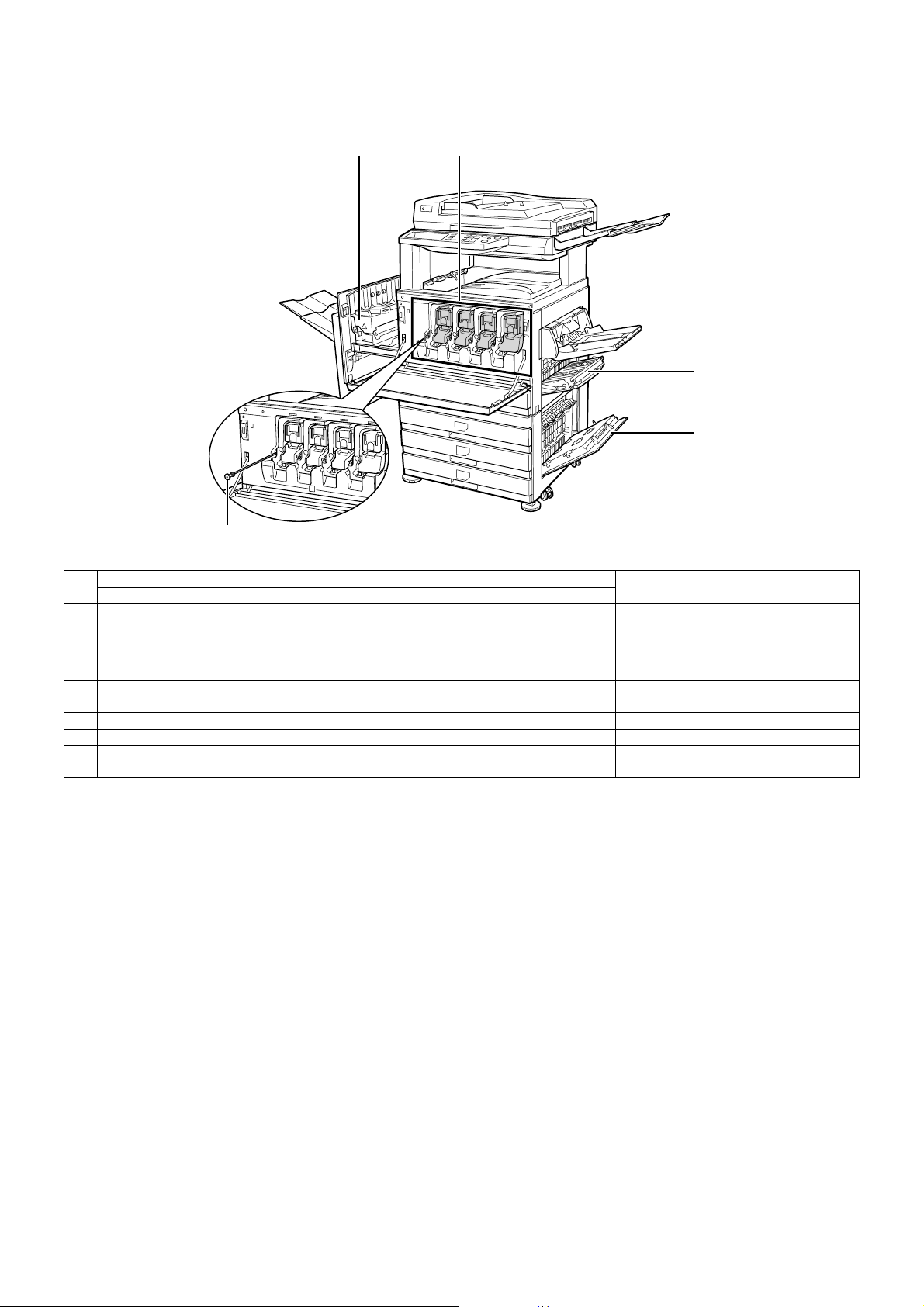
B. Internal structure
16 17
18
19
20
No.
16 Fusing section Fuses transferred images on paper. Note: Since the fusing
17 Toner cartridges Toner is in this cartridge. When toner is empty, replace the
18 Right side cover Opened to process a paper jam in the paper feed section.
19 Paper feed desk right cover Opened to process a paper jam in a peripheral unit.
20 Cleaning lever Use this level to clean the charger. Provided for each toner
Name Function
empty cartridge with a new one.
cartridge.
Parts
Model Note
section is heated to a high
temperature, be careful not
to burn your hands when
processing a paper jam.
AR-C260/C260M EXTERNAL VIEW AND INTERNAL STRUCTURE 6 - 2
Page 24
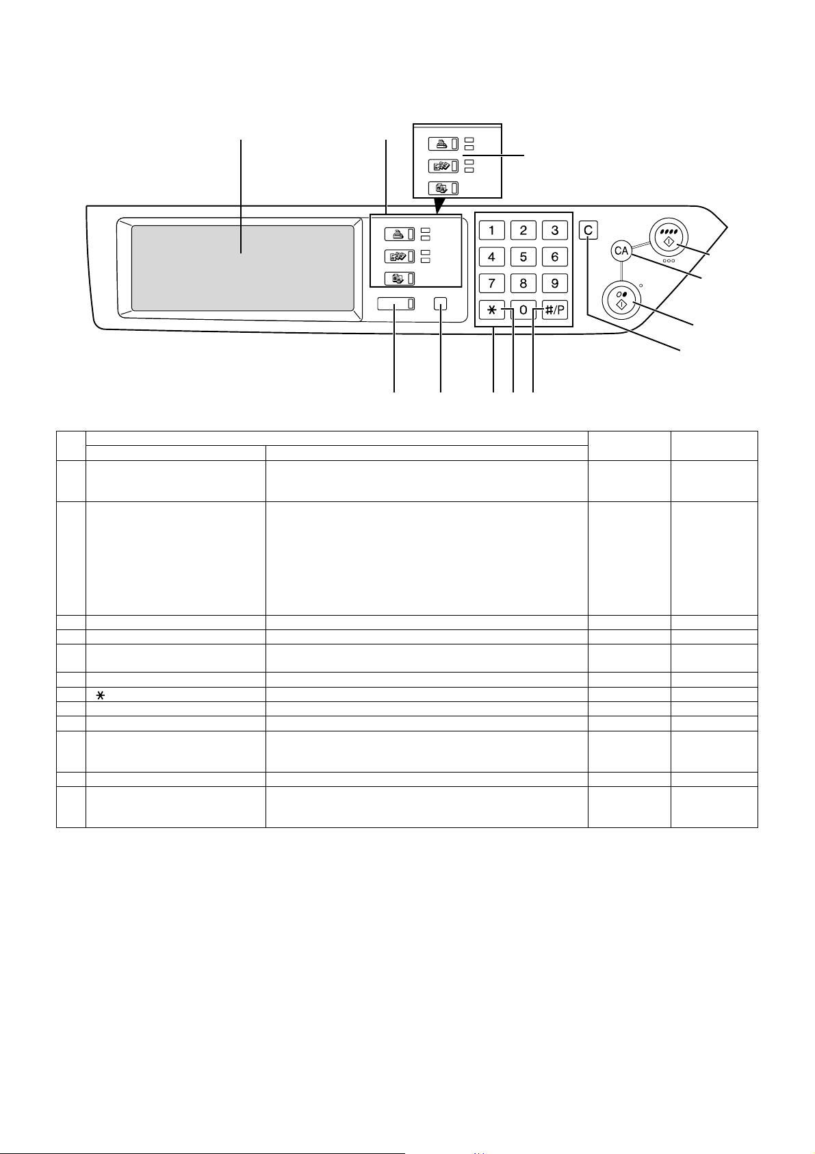
C. Operation panel
No.
1
Parts
Name Function
2
PRINTER
FAX/IMAGE SEND
JOB STATUS USER SETUP
COPY
3
PRINTER
IMAGE SEND
COPY
READY
DATA
LINE
DATA
45
READY
DATA
LINE
DATA
DEPT COUNT END
6
For the model which is
not provided with the FAX
function, this indication is
"IMAGE SEND."
PROGRAM
7
1 Touch panel Displays messages and keys. The display key can be directly
touched to be operated. Provides selection of PRINTER/COPY/
NETWORK SCANNER/FAX mode.
2 Mode select key/ Display lamp Switches the display mode of the touch panel.
[PRINTER] key
READY lamp
DATA lamp
[PRINTER] key: Set to the printer mode.
• READY lamp: ON when reception of print data is allowed.
• DATA lamp: On or flashing during printing or receiving print
data.
[FAX/IMAGE SEND] key *1
Communication lamp
Switches the network scanner (when expanded)/
FAX mode (AR-C250F only).
Data lamp
[COPY] key Switches to the copy mode.
3 [JOB STATUS] key Displays the current job status.
4 [USER SETUP] key Used to adjust contrast of the touch panel and set the key operator
program.
5 10-key pad Used to input figures for various setups.
6 [ ] key ([DEPT COUNT END] key) Used in the copy function and the FAX function.
7 [#/P] key ([PROGRAM] key) Used when dialing in the copy function and the FAX function.
8 [C] key (Clear key) Used in the copy function and the FAX function.
9 B/W [START] key Used during outputting B/W copy in the copy function, during
scanning B/W images in the network scanner function, and during
scanning a send document in the FAX function.
10 [CA] key ([ALL CANCEL] key) Used in the copy function and the FAX function.
11 Color [START] key Used during outputting a full-color or single-color copy in the copy
function and during scanning color images in the network scanner
function.
*1: For the AR-C250S, [IMAGE SEND] key.
CLEAR
Color
CLEAR ALL
B/W
Model Note
START
11
10
9
8
AR-C260/C260M EXTERNAL VIEW AND INTERNAL STRUCTURE 6 - 3
Page 25
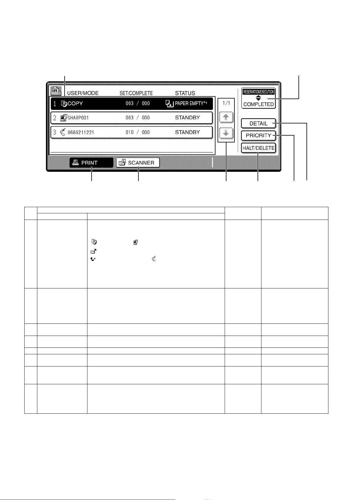
D. Job status display
The job status display is shown by pressing the [JOB STATUS] key on the operation panel.
The list of jobs which are reserved, being executed, or completed is displayed to allow checking the job contents or to delete (terminate) jobs.
1
3 456
∗ The above example shows the job list of reservation and execution.
No.
1 Job list Displays the list of reservation and execution. Tough the key (3),
2 Mode select key This key is displayed only in the job status display in the FAX
3 [PRINT] key Displays the list of the output jobs in all the modes (printer, copy,
4 [SCANNER] key Displays only the jobs of the network scanner function.
5 Display select key Switches the page of displayed job list.
6 [HALT/DELETE] key Halts or deletes a job which is being executed or a reserved job.
7 [PRIORITY] key This key is valid only in the job status display in the FAX mode.
8 [DETAIL] key This key is displayed only on the job status display in the print
Name Function
Display of inside of touch panel
(4) or (5) to select the mode and display the job list.
The icon in front of each job name indicates the job mode.
Copy mode Printer mode
Network scanner mode
FAX mode (Send job) FAX mode (Receive job)
When the job list of reservation and execution is displayed, each
job on the list serves as a key. To terminate the output, touch the
job key to select the job and press [HALT/DELETE] key (6)
([PRIORITY] key (7)).
mode, and is used to switch the job list display to the
[RESERVATION/EXECUTION] job or the [COMPLETED] job.
[RESERVATION/EXECUTION] job: Displays the list of reserved
or executing jobs.
[COMPLETED] job: Displays the list of completed jobs.
and FAX).
∗ When the network scanner function is optionally expanded.
∗ Halt/delete during execution cannot be made.
Touch and select the reserved FAX job to set the highest priority
on the job.
mode.
It is valid only for a print job from PC.
The details of the selected job are displayed. Also used to
change the specified output paper.
7
Model Note
∗ Paper empty of status
display
If the status display is in paper
empty, the specified size
paper is exhausted. (Need to
be supplied.) To print on
another size paper already
set, touch and select the job
and touch the detail key (8) to
change the size.
2
8
AR-C260/C260M EXTERNAL VIEW AND INTERNAL STRUCTURE 6 - 4
Page 26
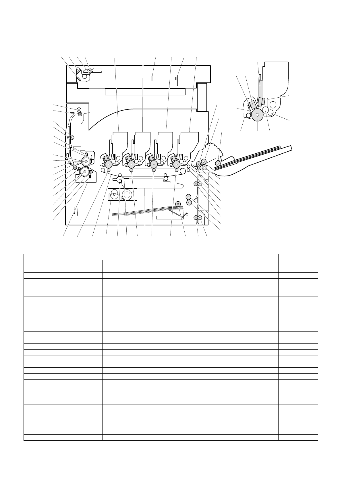
E. Cross section
59
58
56
54
53
52
50
49
48
47
46
45
44
43
42
41
2134 5 6 7 8
57
55
17 18
2425 26
202122 23
19
39
3840
27
28
29
30
31
32
33
34
35
36
37
15
11
10
9
12
13
16
51
14
No.
1 No. 3 mirror Leads a document image to the CCD.
2 No. 2 mirror Leads a document image to No. 3 mirror.
3 No. 1 mirror Leads a document image to No. 2 mirror.
4 Scanner lamp Radiates light on a document for the CCD to scan the document
5 Yellow toner cartridge Attaches yellow toner to electrostatic latent images on the
6 Magenta toner cartridge Attaches magenta toner to electrostatic latent images on the
7 Cyan toner cartridge Attaches cyan toner to electrostatic latent images on the
8 Black toner cartridge Attaches black toner to electrostatic latent images on the
9 Discharge lamp Discharges the photoconductor.
10 Main charger unit Charges the magenta photoconductor negatively.
11 LED unit Converts the color component image signal sent from the ICU PWB
12 Doctor blade Regulates the toner quantity on the developing roller.
13 Supply roller Supplies toner to the developing roller.
14 Developing roller Attaches toner to the photoconductor.
15 Cleaning blade Cleans residual toner from the photoconductor.
16 OPC drum unit Forms electro-static latent images.
17 CCD lens Reduces document images (light) and projects it to the CCD.
18 CCD PWB Reads document images (photo signals) and converts them into
19 Transfer roller (K) Applies the transfer voltage to the transfer belt.
20 Transfer roller (C) Applies the transfer voltage to the transfer belt.
21 Transfer roller (M) Applies the transfer voltage to the transfer belt.
22 Transfer roller (Y) Applies the transfer voltage to the transfer belt.
Name Function
image.
photoconductor.
photoconductor.
photoconductor.
photoconductor.
into LED light, and radiate it to the OPC drum.
electrical signals.
Parts
Model Note
AR-C260/C260M EXTERNAL VIEW AND INTERNAL STRUCTURE 6 - 5
Page 27

No.
23 Transfer belt Transfers toner images of the photoconductor onto paper.
24 Waste toner box (Transfer
section)
25 Lift-up unit Lifts the transfer belt.
26 Paper pickup roller (No. 1 tray) Sends paper to the paper feed roller.
27 Idle roller Applies a pressure to paper and the transport roller to provide
28 Manual paper feed roller Feed paper to the paper transport section.
29 Paper pickup roller Sends paper to the paper feed roller. Manual paper
30 Separation roller Separates paper to prevent double feed.
31 Manual paper transport roller Transports paper to the resist roller.
32 Upper resist roller Transports paper to the transfer section.
33 Lower resist roller Transports paper to the transfer section.
34 Idle roller Prevents paper skew.
35 Paper transport roller 1 Transports paper to the resist roller.
36 Paper feed roller (No. 1 tray) Feed paper to the paper transport section.
37 Separation roller (No. 1 tray) Separates paper to prevent double feed.
38 Idle roller Applies a pressure to paper and the transport roller to provide
39 Paper transport roller 2 Transports paper to the transport roller 1.
40 Fusing unit Fuses toner on paper.
41 Lower heat roller thermistor Detects the temperature on the fuser roller surface.
42 Lower heat roller thermostat Detects an abnormally high temperature and turns off the heater
43 Lower heat roller Heats and presses toner on paper to fuse toner on paper.
44 Lower heater lamp Heats the lower fuser roller.
45 Lower separation pawl Mechanically separates paper which was not separated naturally
46 Fusing transport roller Transports paper after fusing.
47 Idle roller Applies a pressure to paper and the transport roller to provide
48 Gate Switches the paper exit path. (face up, face down)
49 Upper heater lamp Heats the heat roller.
50 Upper heat roller Heats and presses toner on paper to fuse toner on paper.
51 OPC drum Forms latent static electrostatic images with LED light.
52 Upper heat roller thermistor Detects the temperature on the heat roller surface.
53 Upper heat roller thermostat Detects an abnormally high temperature and turns off the heater
54 Idle roller Applies a pressure to paper and the transport roller to provide
55 Transfer belt cleaning blade Cleans toner on the transfer belt.
56 Paper transport roller 3 Transport paper to the paper exit roller.
57 Belt waste toner transport shaft Transports waste toner on the transfer belt to the waste toner box.
58 Paper exit roller Discharges paper to outside of the machine.
59 Idle roller Applies a pressure to paper and the transport roller to provide
Name Function
Collects waste toner on the transfer belt.
transport power of the transport roller to paper.
transport power of the transport roller to paper.
lamp.
from the lower heat roller.
transport power of the transport roller to paper.
lamp.
transport power of the transport roller to paper.
transport power of the transport roller to paper.
Parts
Model Note
feed section
AR-C260/C260M EXTERNAL VIEW AND INTERNAL STRUCTURE 6 - 6
Page 28
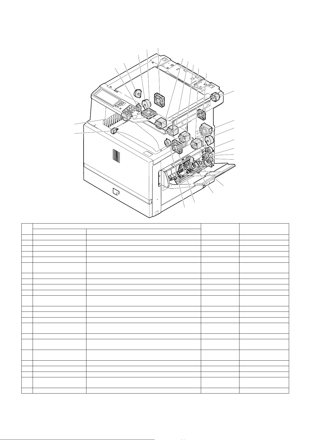
F. Motors, clutches, solenoids, fans
5
4
3
2
1
7
8
9
10
11
14
13
12
15
16
18
17
19
No.
23
22
Parts
Name Function
20
6
21
Code, signal name Type
1 Exit select gate solenoid Drives the exit path select gate. GSS Electromagnetic solenoid
2 Offset motor (Slide motor) Drives the paper exit offset. OSM Stepping motor
3 Fusing drive motor Drives the fusing unit. FUSM Stepping motor
4 Exhaust fan motor 1 Exhaust and cools the fusing section. VFMP DC motor
5 Exhaust fan motor 2 Exhaust and cools the fusing section. VFMS DC motor
6 Power unit cooling fan
Cools the power unit. PSFM DC motor
motor
7 Drum motor (Y) Drives the yellow photoconductor unit. DM_Y Stepping motor
8 Drum motor (M) Drives the magenta photoconductor unit. DM_M Stepping motor
9 Drum motor (C) Drives the cyan photoconductor unit. DM_C Stepping motor
10 Drum motor (K) Drives the black photoconductor unit. DM_K Stepping motor
11 Printer controller cooling
Cools the printer controller.
fan motor
12 PS motor Drives and turns ON/OFF the resist roller. PSM Stepping motor
13 Process cooling fan motor Exhaust and cools the process section. PCFM DC motor
14 Scanner motor Drives the scanner unit. SM Stepping motor
15 PS front clutch Transmits power of the paper feed motor to the manual paper
MTRC Electromagnetic clutch
feed unit. (Controls ON/OFF.)
16 Paper feed motor Drives the paper feed section and the paper transport section. PFM DC servo motor
17 Paper feed clutch Transmits power of the paper feed motor to each transport
TRC Electromagnetic clutch
roller. (Controls ON/OFF.)
18 Manual paper feed clutch Controls ON/OFF of the manual paper feed roller. Presses the
MPFC Electromagnetic clutch
paper pickup roller to paper.
19 Paper feed drive clutch Controls ON/OFF of the paper feed roller. CPFC1 Electromagnetic clutch
20 No. 1 cassette lift-up motor Drives the lift plate. LUM1 Synchronous motor
21 Belt lift-up motor Lifts the transfer belt unit. BLUM Stepping motor
22 Calibration plate open/
Switches the image density sensor. CALS Electromagnetic solenoid
close solenoid
23 Transfer belt motor Drives the transfer belt. BTM Stepping motor
AR-C260/C260M EXTERNAL VIEW AND INTERNAL STRUCTURE 6 - 7
Page 29
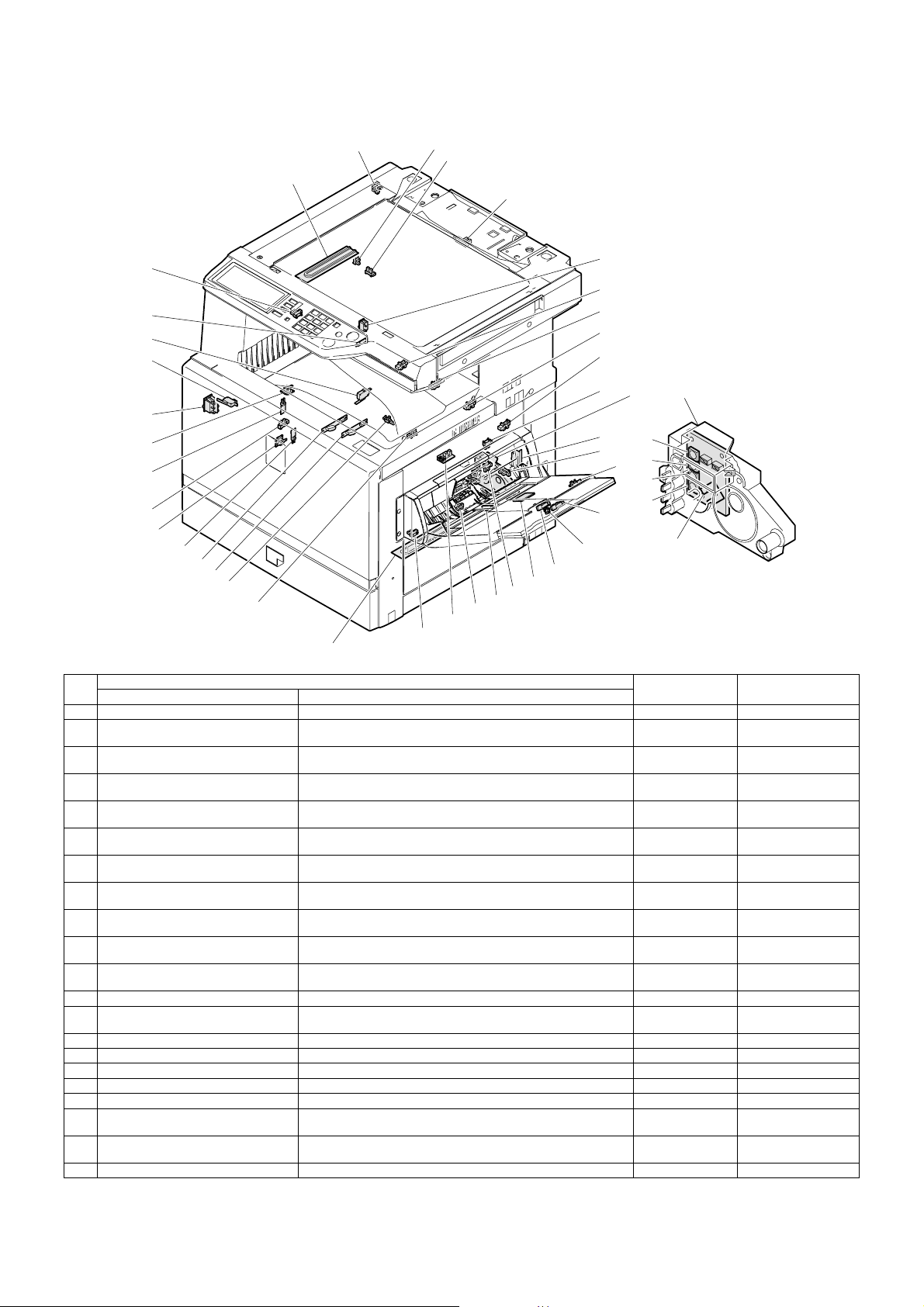
G. Sensors, switches and heaters
5
3
4
1
2
43
7
8
42
41
40
9
10
11
12
Paper tray
lift-up unit
39
13
38
37
36
35
34
33
44
32
31
27
28
24
25
26
22
23
29
30
16
14
17
15
18
19
21
20
Front / right side / top view
No.
1 Dehumidifier heater Dehumidifies the scanner section. DH (Japan only)
2 O/C open/close sensor Detects open/close of the document cover. (A timing signal of
3 Offset home position sensor Detects the offset home position. HPOS Photo sensor (Photo
4 Paper exit tray full detection Detects full of the face down paper exit tray. TFD2 Photo sensor (Photo
5 Mirror home position sensor Detects the scanner home position. MHPS Photo sensor (Photo
7 Dehumidifier heater switch Turns ON/OFF the dehumidifier heater installed in the scanner
8 Toner empty sensor (Y) Detects toner empty (Y). TES_Y Photo sensor (Photo
9 Toner empty sensor (M) Detects toner empty (M). TES_M Photo sensor (Photo
10 Toner empty sensor (C) Detects toner empty (C). TES_C Photo sensor (Photo
11 Toner empty sensor (K) Detects toner empty (K). TES_K Photo sensor (Photo
12 No. 1 paper transport sensor Detects paper in front of the resist roller. PPD1 Photo sensor (Photo
13 Paper feed door open detection Detects open/close of the paper feed door. DSWR Micro switch
14 Manual feed paper empty detection Detects paper empty on the paper tray. MPED Photo sensor (Photo
15 Manual feed tray pulling out detection 2 Detects the paper tray position. MTOP2 Contact switch
16 No. 1 cassette paper size detection 1 Detects the paper size set by the paper size set blocks. C1SS1 Contact switch
17 No. 1 cassette paper size detection 2 Detects the paper size set by the paper size set blocks. C1SS2 Contact switch
18 No. 1 cassette paper size detection 3 Detects the paper size set by the paper size set blocks. C1SS3 Contact switch
19 No. 1 cassette paper size detection 4 Detects the paper size set by the paper size set blocks. C1SS4 Contact switch
20 No. 1 cassette lift-up position detection 1 Detects the lift plate position. (Detects the paper quantity.) C1PD1 Photo sensor (Photo
21 Manual feed paper length detection 2 Detects the paper length. MPLD2 Photo sensor (Photo
22 Manual feed tray pulling out detection 1 Detects the paper tray position. MTOP1 Contact switch
Name Function
document size detection is produced.)
(reading) section and the paper feed section.
Parts
Code, signal name Type
OCSW Photo sensor (Photo
DHSW
(Japan only)
transmission)
transmission)
transmission)
transmission)
—
transmission)
transmission)
transmission)
transmission)
transmission)
transmission)
transmission)
transmission)
AR-C260/C260M EXTERNAL VIEW AND INTERNAL STRUCTURE 6 - 8
Page 30
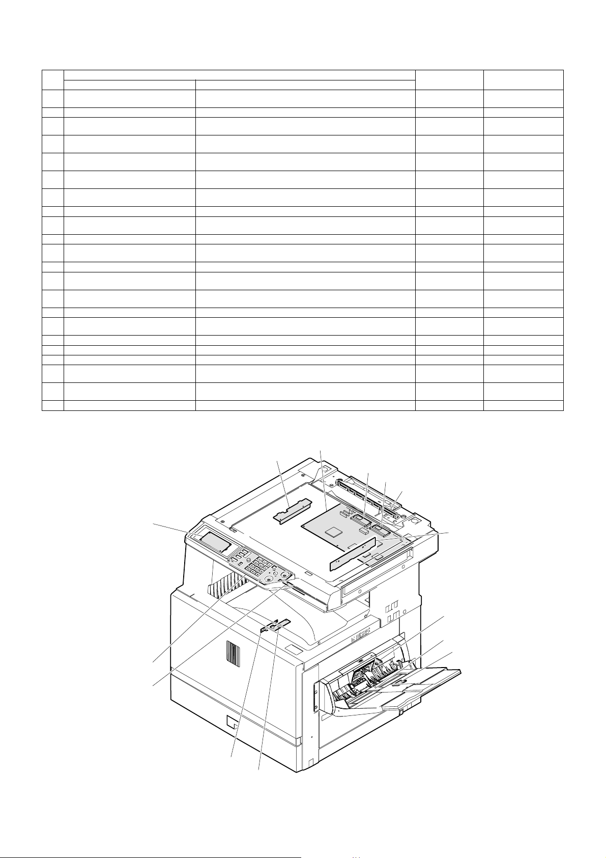
No.
23 Manual feed paper length detection 1 Detects the paper length. MPLD1 Photo sensor (Photo
24 Humidity sensor Detects the ambient humidity. HUD —
25 No. 1 cassette paper feed detection Detects paper exit from No. 1 paper tray. PFD1 Photo sensor (Photo
26 Manual feed paper width detection Detects the paper width. MPWS Volume (Variable
27 No. 1 cassette lift-up upper limit
detection
28 PS front sensor Detects paper in front of PS. PPD2 Photo sensor (Photo
29 No. 1 cassette paper empty detection Detects paper empty on the paper tray. PED1 Photo sensor (Photo
30 Dehumidifier heater Dehumidifier hater for the main body cassette. (Japan only) DH —
31 Belt lift-up upper limit detection Detects lift-up or lift-down of the transfer belt. BLUD Photo sensor (Photo
32 Belt waste toner full detection Detects belt waste toner full. BTNF Contact switch
33 Color toner concentration (process
control) sensor/Auto image Reg.
34 Lower heat roller thermistor Detects the temperature on the heat roller surface. THSD Thermistor
35 Lower heat roller thermostat Detects an abnormally high temperature and turns off the heater
36 Machine paper exit sensor 1 Detects discharged paper. POD1 Photo sensor (Photo
37 Upper heat roller thermistor Detects the temperature on the heat roller surface. THSU Thermistor
38 Upper heat roller thermostat Detects an abnormally high temperature and turns off the heater
39 Main switch Turns ON/OFF the main power. MSW Seesaw switch
40 Front door open detection Detects open/close of the front door. DSWF Micro switch
41 Paper exit door open detection Detects open/close of the paper exit door. DSWL Micro switch
42 Face-up paper exit tray full detection Detects full of the face-up paper exit tray. TFD Photo sensor (Photo
43 Machine paper exit sensor 2 Detects discharged paper. POD2 Photo sensor (Photo
44 Black toner concentration sensor Detects black patch density for toner concentration PCS_B —
Name Function
Detects the upper limit position of paper. LUD1 Photo sensor (Photo
Detects the toner patch density (color toner) in image density
correction operation. 2-sensors on PWB.
lamp.
lamp.
Parts
Code, signal name Type
transmission)
transmission)
resistor)
transmission)
transmission)
transmission)
transmission)
PCS_C Photo sensor (Photo
HLTS2 Thermostat
HLTS1 Thermostat
transmission)
Thermal switch
transmission)
Thermal switch
transmission)
transmission)
H. PWB 1
1
2
3
4
5
13
6
7
8
14
12
11
10
9
Front / right side / top view
AR-C260/C260M EXTERNAL VIEW AND INTERNAL STRUCTURE 6 - 9
Page 31
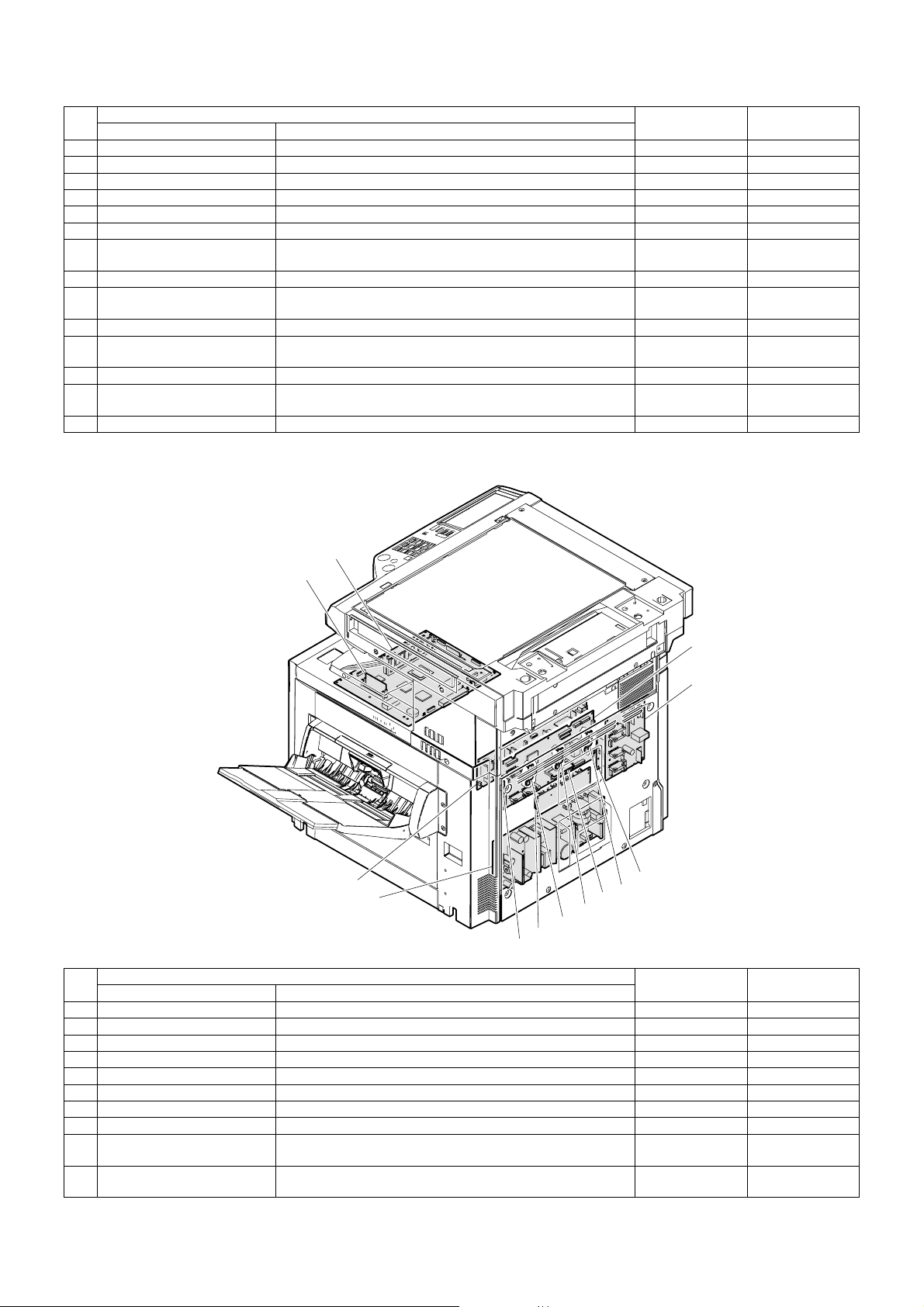
No.
Name Function
Parts
1 CL inverter PWB Drives the xenon lamp.
2 MFP PWB Corrects images from the CCD and controls the operation panel.
3 Flash PWB (OP) Includes the program to drive the OP PWB.
4 Flash PWB (MFP) Includes the program to drive the MFP PWB.
5 Document detection LED PWB Emits light for document size detection.
6 CCD PWB Converts document images into electric signals.
7 Lift-up unit PWB tray Detects the cassette size and interfaces the cassette lift-up motor
signals.
8 Manual feed VR PWB Outputs manual feed width signals.
9 Process control PWB (for
Outputs the black toner density on the transfer belt.
black)
10 Process control PB (for color) Outputs the color toner density on the transfer belt.
11 Document detection light
Outputs the document size detection signal.
receiving PWB
12 Operation PWB Outputs the key operation signal.
13 INV/LVDS PWB Interfaces LCD from the MFPPWB and the touch panel signal,
and drives the LCD backlight.
14 Temp sensor PWB Temp/humidity sensor readings.
H. PWB2
16
15
Code, signal name Type
No.
24
23
Parts
Name Function
22
20
21
20
20
15 Flash PWB (ICU) Includes the program to drive the ICU PWB.
16 ICU PWB Performs image process and controls LED.
17 PCU PWB Controls the engine section.
18 Driver PWB Controls the DC load power and drive the motor.
19 AC power PWB Controls the power on the primary side.
20 LED DL PWBs Discharges electric charges on the OPC drums.
21 Flash PWB (PCU) Includes the program to drive the PCU PWB.
22 High voltage TC PWB Produces the transfer voltage.
23 DC power PWB Outputs the voltage on the secondary side, and controls the
heater lamp.
24 High voltage MC PWB Produces a high voltage for the main charger and the developing
bias voltage.
17
18
19
20
Right side / top rear / view
Code, signal name Type
AR-C260/C260M EXTERNAL VIEW AND INTERNAL STRUCTURE 6 - 10
Page 32

[7] DESCRIPTIONS OF EACH SECTION
THSD
HLTS2
1. Fusing section
(2) Electrical section
3
21
Fusing unit
POD1
THSU
A. Operational descriptions
(1) Outline
This section performs the following function and operation.
1) Toner attached to paper in the transport section is fused onto
paper by heat and pressure of the heat roller.
Drawer connector (13+4pin)
+24VL
1
3
5
4
21
A4
A5
B3
B4
B5
A1
A2
2
1
3 HL2N
FULHin
+5V
POD1
THSD
GND2
THSU
GND2
HL1N
L2
HL1
HLTS1
HL2
THSD
A4
A3
B6B1
B4
B3
B2
A7
A6
2
1
3
FUSM_B\
Driver PWB
CN8(20pin)
FUSM
Fusing drive connection gear
FUSM_B
FUSM_A\
CN1(6pin)
81920
6
+24V
FUSM_A
CN2(34pin)
+24V
654321
DSWLin
DSWLout
7
+24V
9
+24V
1
+24V
3
FUSM_B\
5
FUSM_A\
7
FUSM_B
9
FUSM_A
11
DSWL
16
2
1
DSWL
+24V
+24V
FUSM_B\
FUSM_A\
FUSM_B
FUSM_A
DSWL
L2
3
CN3
L2 CN3-3
N2 CN3-1
FUCHin
2
+5V
6
POD1
8
THSD
10
GND2
1
THSU
GND2
3
1
3
5
7
CN12(34pin)
9
11
16
HL1N
HL2N
21
HL drive circuit
DC power PWB
CN2
765431
CN14(10pin)
PCU
DC-CNT
CN7
8
10
1214
6
4
HL2
MSWON
+24V
HLPR
HL1
HLTS2
21
AR-C260/C260M DESCRIPTIONS OF EACH SECTION 7 - 1
Page 33

(3) Major parts/signals functions and operations
53
2
2
6
2
1
120V 950W
120V 350W
1
1
5
6
6
4
1
1
4
6
4
3
1
2
6
4
No. Name Code, Signal name Function
1 Heat roller
2 Upper/lower separation pawls
3 Heater lamp Upper: HL1, Lower: HL2 Heats the heat rollers.
4 Thermistor Upper: THSU, Lower: THSD Detects the surface temperature of the heat roller. (Keeps the roller surface
5 Thermostat Upper: HLTS1, Lower: HLTS2 Cuts conduction of the heater lamp when an abnormally high temperature is
6 Paper exit sensor POD1 Detects paper discharged from the fusing section.
RW Control signal FUSM_A, A’, B, B’ Drives the fusing section.
RW Control signal FUCHin Fusing unit installation detecting signal
RW Control signal DSWL Left cabinet open/close detection signal
RW Control signal HLPR Heater lamp power relay (in the DC power PWB) drive signal
RW: Abbreviation of Related Wiring, which means the said load is specified in the related figure of the mechanical and the electrical sections.
—
—
(4) Operational descriptions
a. Fusing unit drive
To drive the fusing unit, drive power is transmitted from the drive motor
(FUSM) through the connection gear to the upper heat roller gear.
The drive motor (stepping motor) is driven by the motor drive IC in the
driver PWB according to the control signal sent from the PCU.
3
Heats and presses toner to fuse it on paper. Silicon rubber rollers are used
as the upper and the lower heat rollers. Teflon tube is wound around the
upper heat roller.
Mechanically separate paper from the heat roller, which was not separated
naturally.
temperature at a constant level.)
detected.
c. Fusing operation
Color toner of YMCK on paper is heated and pressed by the heat rollers to be fused on paper.
At that time, color toner of YMCK is mixed to reproduce nearly actual
colors of document images.
5
Driver
PWB
b. Heater lamp drive
The surface temperature detected by the thermistor is sent to the PCU.
When the temperature is lower than the specified level, the PCU sends
the heater lamp lighting signal to the heater lamp drive circuit in the DC
power PWB.
The triac in the heater lamp drive circuit is turned on to apply AC power
to the heater lamp, which turns on to heat the heat rollers.
The thermostats are provided as a safety measure to prevent against
an abnormally high temperature of the heat rollers.
When the thermostat is opened, the power supply (AC neutral) to the
heater lamp is cut off.
FUSMPCU
AR-C260/C260M DESCRIPTIONS OF EACH SECTION 7 - 2
The upper and the lower heat rollers are provided to heat from above
and below. This is because it is necessary to heat four layers of toner
from above and below and right and left to fuse it on paper.
The upper and lower heat rollers are of silicon rubber. This is because
of the following reasons:
1) To provide a greater nip quantity and a higher heating capacity for
paper.
2) The soft, flexible rollers press multi-layer toner without deformation
to fuse on paper.
3) An even pressure is applied to an uneven surface of multi-layer
toner.
Page 34

d. Fusing temperature control
The temperature sensor is provided at the center of the upper and the
lower heat rollers.
The temperature sensor at the center detects the heat roller temperature and controls the heater lamp to keep the fusing temperature at the
specified level.
The fusing temperature is switched according to the machine condition
and paper type selected.
Upper heat roller Lower heat roller
Ready state 170°C 120°C
Power save mode 143°C OFF
Print mode Normal paper 175°C 140°C
OHP sheet 170°C 155°C
Heavy paper 1 175°C 136°C
Heavy paper 2 175°C 145°C
Envelope 180°C 145°C
B. Disassembly/Assembly/Maintenance
(1) Fusing section maintenance target parts
✕: Check (Clean, replace, or adjust as necessary.) ❍: Clean ▲: Replace ∆: Adjust ✩: Lubricate ❏: Shift position
Unit name No. Part name
Fusing section 1 Upper heat roller ✕ ✕▲✕▲✕▲✕▲Replace at 100K or within 2
2 Lower heat roller ✕ ✕▲✕▲✕▲✕▲Replace at 100K or within 2
3 Heat roller gear ✕ ✕▲✕▲✕▲✕▲
4 Heat roller bearing ✕ ✕▲✕▲✕▲✕ ▲
5 Separation pawl ✕ ✕▲✕▲✕▲✕▲
6 Thermistor ✕ ✕▲✕▲✕▲✕▲
— Bearings ✕ ✕✕✕✕✕✕✕✕
7 Gears ✕ ✩✩✩✩✩✩✩✩
8 Paper guides ❍
9 Paper exit roller ✕ ✕✕✕✕✕✕✕✕
— Fusing unit ✕▲✕▲✕▲✕▲Replace the unit at 100K or
When
calling
50K 100K 150K 200K 250K 300K 350K 400K Remark
years.
years.
❍❍❍❍❍❍❍❍
within 2 years.
8
4
1
1
5
5
10
6
6
4
2
2
6
6
4
4
4
9
5
5
4
7
3
3
4
4
9
8
AR-C260/C260M DESCRIPTIONS OF EACH SECTION 7 - 3
Page 35

(2) Maintenance parts replacement procedure
a. Fusing unit removal
1) Open the left cabinet.
2) Loosen the roller knob (A) and remove the fusing unit (B).
c. Lower thermistor
1) Remove the fusing unit from the machine.
2) Remove the screws, and remove the fusing front PG (A).
3) Remove the connector, the screw, and the harness, and remove
the thermistor (B).
B
A
B
A
b. Upper thermistor
1) Remove the fusing until from the machine.
2) Remove the screw and the harness cover (A).
3) Remove the connector, the screw, and the harness, and remove
the thermistor (B).
A
B
d. Upper heater lamp
1) Remove the fusing unit from the machine.
2) Remove the screw and remove the fusing front cover (A). Remove
the harness cover (B).
3) Remove the connector, the screw, and the lamp holder (C), and
remove the upper heater lamp.
B
C
D
A
e. Lower heater lamp
1) Remove the fusing unit from the machine.
2) Remove the screw, and remove the fusing front cover (A).
3) Remove the screw, and remove the fusing front PG (B).
4) Remove the connector, the screw, and the lamp holder (C), and
remove the lower heater lamp.
A
C
AR-C260/C260M DESCRIPTIONS OF EACH SECTION 7 - 4
D
B
Page 36

f. Upper heat roller, bearing, gear
1) Remove the fusing unit from the machine.
2) Remove the lever (A), and release the roller pressure.
3) Remove the screw.
A
4) Open the upper fusing section.
6) Remove the C-ring and the bearing, and remove the gear (A) and
the heat roller (B).
A
g. Lower heat roller, bearing
1) Remove the fusing unit from the machine.
A
2) Remove the screw, and open the upper fusing section.
3) Remove the lower heat roller unit (B).
4) Remove the C-ring and the bearing (A), and remove the heat roller
(B).
B
B
5) Remove the heat roller upper unit (B).
B
∗ When assembling, put the flanges of the upper bearings outside of
the frames F and R.
Frame FFrame R
AA
h. Paper guide
1) Remove the fusing unit from the machine.
2) Remove the screw, and remove the paper guide.
Note: Refer to the adjustment (ADJ13) when installing the paper
guide.
B
Frame FFrame R
AR-C260/C260M DESCRIPTIONS OF EACH SECTION 7 - 5
Page 37

i. Paper exit roller
1) Remove the fusing unit from the machine.
2) Open the upper fusing section.
3) Remove the E-ring (A), and shift the bearing (B).
4) Remove the paper exit roller unit (C).
5) Remove the POD1 connector.
6) Remove the screw, and slide and remove the lower separation
pawl mounting plate.
C
A
C
B
5) Remove the E-ring, the gear, the pin, and the bearing.
j. Lower separation pawl
1) Remove the fusing unit from the machine.
2) Open the upper fusing section.
3) Remove the paper exit roller unit.
4) Lift the separation pawl and shift it to the right and lift it from the
heat roller.
B
A
C
7) Rotate the separation pawl in direction A and remove if from the
mounting plate. Remove the spring.
A
Note: When attaching the separation pawl, check that the separation
pawl is in contact with the heat roller.
AR-C260/C260M DESCRIPTIONS OF EACH SECTION 7 - 6
Page 38

2. Transfer section
A. Operational descriptions
(1) Outline
This section functions and operates as follows:
1) A high, positive voltage is applied to the transfer roller to charge the
transfer belt and paper on it positively, attracting negatively
charged toner images on the OPC drum onto paper.
(2) Electrical and mechanical sections
Transfer belt unit
(20pin) (14pin)
BTNF
12
NC
13
CALS/
9
GND2
14
BSEN_LED
7
PCS_K
8
GND2
1
PCS_C
4
ASEN_LED
3
GND2
10
REGSEN
5
TS (CL)
6
BTM /B
16
BTM /A
17
BTM B
18
BTM A
19
+24V
15
GND (FLAME)
20
FG
PCSC
Color PC &
Auto reg
sensor
(2pin)
12
Process control
shutter
CALS
(5pin)
+24V
11
CALS/
13
GND2
7
PCSC
3
B SEN LED
1
REG SEN
5
+5V
9
PCSK
10
A SEN LED
8
GND2
12
PCSK
Lift-up cam
(6pin)
BLUM B/
1
BLUM A/
2
BLUM B
3
BLUM A
4
+24V
5
+24V
6
(4pin)
BLUD
BLUM
(5pin)
Drawer connector
(24pin)
BTNF
14
NC
CN9
2
(24pin)
CALS/
21
BELT CHim
12
A SEN LED
6
PCSK
4
GND2
13
PCSC
10
B SEN LED
8
GND2
11
REG SEN
22
+5V
24
BTM B/
9
BTM A/
7
BTM B
5
BTM A
3
+24V
1
BTM
HV REM
GND
FG
CN2 (10pin)
HV (MC) PWB
Drive gear
TC C
45678910123
TC M
TC Y
1
2
3
4
5
6
CN1 (8pin)
BTM B/
BTM A/
BTM B
BTM A
+24V
+24V
1
2
(NC)FGTC K
+24V
BTN F
GND2
DSNRout DSWR
+24V
8
GND2
7
GND2
6
HV STB
5
HV DATA
4
HV CLK
3
HV REM
2
1
1
CN17
5
(28pin)
8
7
4
2
6
PCU PWB
CN6 (10pin)
30 34
+24V
3579810246
BTNF
THVY
THVM
THVC
THVK
HV (TC) PWB
+24V
1
(NC)
+5V
1
BLUD
2
GND2
3
4
5
CN1 (10pin)
FG
TCK
TCY
TCM
TCC
HVREM
GND
FG
2
3
4
5
6
7
8
9
10
AR-C260/C260M DESCRIPTIONS OF EACH SECTION 7 - 7
Page 39

(3) Major parts/signals functions and operations
5
7
8
4
3
3
9
9
1
10
2
4
4
2
2
6
2
8
1
24 24 244
7
8
5
9
9
3
3
10
1
3
9
9
3
10
10
1
4
4
2
2
4
6
8
5
5
4
2
2
4
4
2
2
7
7
8
8
No. Name Code, signal name Function
1 Transfer belt — Transfers toner images on the OPC drum onto paper.
2 Transfer roller — Applies a transfer voltage to the transfer belt.
3 Belt cleaning blade — Cleans and removes toner from the transfer belt.
4 Transfer discharge sheet — Discharges the transfer belt.
5 Transfer belt cleaning roller — Removes paper dust from the transfer belt.
6 Transfer belt drive roller — Drives the transfer belt.
7 Transfer belt follower roller — Transfer drive follower roller
8 Transfer belt cleaning brush — Cleans the back surface of the transfer belt.
9 Process control sensor Monochrome: PCSK
10 Transfer waste toner tank — Collects waste toner on the transfer belt.
RW Belt motor BTM Drives the transfer belt.
RW Calibration solenoid CALS Drives the shutter on the process control sensor.
RW Waste toner full detection switch BTNF Detects waste toner full in the waste toner box.
RW Belt lift-up motor BLUM Lifts up the transfer belt unit.
RW Belt lift-up sensor BLUD Detects the position of the transfer belt unit.
RW Control signal TC (K, C, M, Y) Each color transfer high voltage control signal
RW Control signal THV (K, C, M, Y) Each color transfer high voltage
RW: Abbreviation of Related Wiring, which means the said load is specified in the related figure of the mechanical and the electrical sections.
Color: PCSC
Detects the toner patch density in image density correction.
AR-C260/C260M DESCRIPTIONS OF EACH SECTION 7 - 8
Page 40

(4) Operational descriptions
a. Transfer belt drive
The transfer belt drive power is transmitted from the drive motor (BTM)
to the transfer drive roller.
The motor (stepping motor) is driven by the drive signal sent from the
PCU.
b. Applying a transfer high voltage to the transfer roller
According to the high voltage control signal from the PCU, the signal is
converted into a transfer high voltage control signal with the HV (MC)
PWB, and sent to the HV (TC) PWB.
According to each color transfer high voltage control signal, a high voltage is applied to each transfer roller from the transfer high voltage HV
(TC) PWB through the connection spring to each transfer roller.
e. Transfer belt unit up and down
In color print, the transfer belt is in contact with four OPC drums. In
black and white print, the transfer belt unit moves down so that only the
black OPC drum is in contact with the transfer belt.
This up-and-down movement of the transfer belt is performed by the
lift-up motor (BLUM), the lift-up cam, and the unit position sensor
(BLUD).
When the left cabinet is opened for jam process, the rotating mechanism of the lift-up unit separates all four OPC drums from the transfer
belt.
• Transfer belt position for color print
The four OPC drums are in contact with the transfer belt by rotation
of the cam in the transfer lift-up unit.
YMC
• Transfer belt position for black print
Only the black OPC drum is in contact with the transfer belt by rotation of the cam in the transfer lift-up unit.
K
c. Process control sensor control
The process control shutter is provided on the process control sensor
of monochrome (PCSK) and color (PCSC). When the shutter is open
(in image density correction and automatic registration), the toner
patch formed on the transfer belt is read by the process control sensor,
and its information is sent to the PCU.
When the shutter is closed, the calibration sheet is read to perform calibration of the sensor itself.
The shutter operation is controlled by the calibration solenoid (CALS).
d. Belt waste toner full detection
Toner scraped by the belt cleaning blade is transported to the waste
toner box by the belt waste toner transport shaft.
When the waste toner box is full, the rotation load of the waste toner
transport shaft increases to turn on the waste toner full detection
switch with the lever by the torque limiter function.
YMC
9mm
• Transfer belt position in jam process or replacement of the transfer
belt
When the left cabinet is opened, the transfer lift-up unit moves down,
and the transfer unit moves by 9mm accordingly.
YMC
K
K
Drive to paadle by blum
Waste toner full detection →
1000 copies → without 24g reset
AR-C260/C260M DESCRIPTIONS OF EACH SECTION 7 - 9
Page 41

B. Disassembly/assembly/maintenance
5
7
8
4
3
3
9
9
1
10
2
4
4
2
2
(1) Transfer section maintenance target parts
✕: Check (Clean, replace, or adjust as necessary.) ❍: Clean ▲: Replace ∆: Adjust ✩: Lubricate ❏: Shift position
Unit name No. Part name
Transfer
section
1 Transfer belt ✕▲✕▲✕▲✕▲Replace at 100K or
2 Transfer roller ✕▲✕▲✕▲✕▲
3 Transfer belt cleaning
blade
4 Transfer discharge sheet ✕❍✕❍✕❍✕❍
5 Transfer belt cleaning
roller
6 Transfer drive roller ✕✕✕✕✕✕✕✕
7 Transfer follower roller ✕✕✕✕✕✕✕✕
8 Transfer discharge brush ✕✕✕✕✕✕✕✕
9 Sensors ✕✕✕✕✕✕✕✕
10 Waste toner tank unit ▲ ✕▲✕▲✕▲✕▲When waste toner full is
11 Transfer belt unit ✕▲✕▲✕▲✕▲Replace the unit at
When
calling
50K 100K 150K 200K 250K 300K 350K 400K Remark
✕▲✕▲✕▲✕▲Replace at 100K or
✕▲✕▲✕▲✕▲
within 2 years.
within 2 years.
detected.
100K or within 2 years.
6
2
8
24 24 244
1
7
TX belt clean blade seals.
8
5
9
9
3
3
10
1
3
9
9
3
10
10
1
4
4
2
2
4
6
8
5
5
4
2
2
4
4
2
2
7
7
8
8
AR-C260/C260M DESCRIPTIONS OF EACH SECTION 7 - 10
Page 42
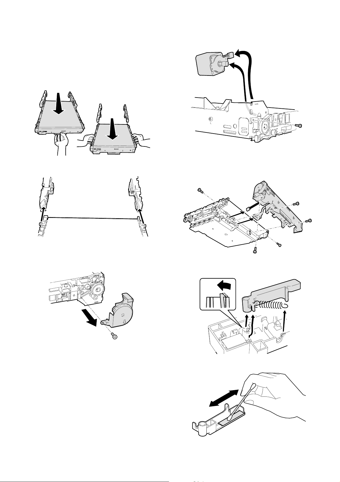
(2) Maintenance parts replacement procedure
a. Transfer unit removal
1) Open the left cabinet, and remove the fusing unit. (Refer to the
section of the fusing unit.)
2) Hold section A of the transfer unit and pull it in the arrow direction
so that you can hold both sides of the unit.
3) Hold both sides B and remove the transfer unit from the machine.
B
A
Note: Be careful not to scratch the surface of the transfer belt.
3) Remove the connector, the screw, and the motor.
c. Process control sensor
1) Remove the transfer unit from the machine.
2) Remove the connector and the screw, and remove the belt drive
unit.
B
A
b. Belt drive motor
1) Remove the transfer unit from the machine.
2) Remove the screw, and remove the belt cover gear.
B
A
3) Remove the spring from the hook section.
4) Remove the hook, and remove the process control shutter.
Cleaning: Clean the calibration sheet. (Wipe with soft, dry cloth.)
AR-C260/C260M DESCRIPTIONS OF EACH SECTION 7 - 11
Page 43
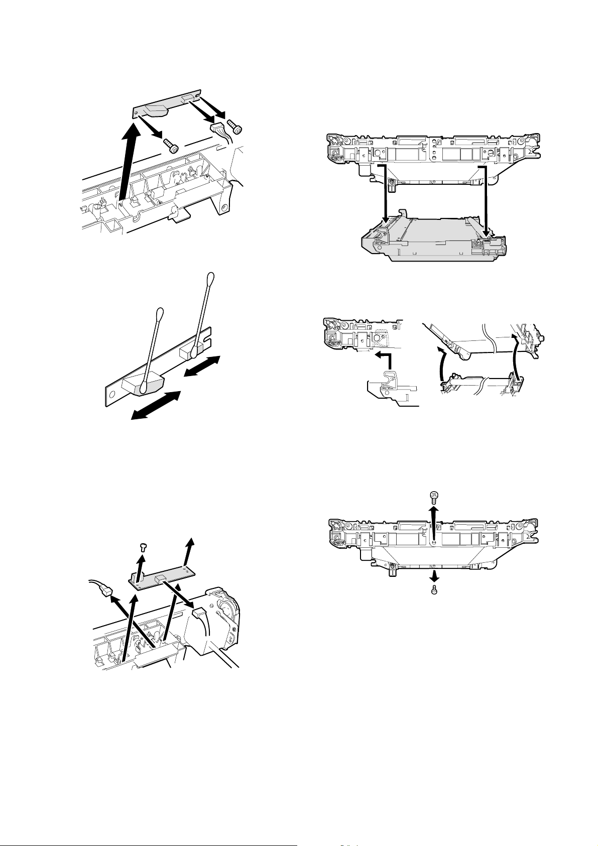
5) Remove the connector, and remove the process control sensor.
Cleaning: Clean the sensor surface.
e. Waste toner tank unit
1) Remove the transfer unit from the machine.
2) Remove the connectors and the screws, and remove the belt drive
unit.
3) Remove the waste toner tank unit.
Note for assembly:
Insert the notches A and B of the waste toner tank unit into the positions in the transfer frame indicated in the figure below.
A
d. PWB
1) Remove the transfer unit from the machine.
2) Remove the connector and the screw, and remove the belt drive
unit.
3) Remove the spring from the hook section.
4) Remove the process control shutter.
5) Remove the connector (A).
6) Remove the connector (B) and the screw, and remove the PWB.
A
B
B
f. Transfer belt
1) Remove the transfer unit from the machine.
2) Remove the connector and the screw, and remove the belt drive
unit.
3) Remove the lower screw.
Front
Rear
Note: If the upper screw is removed and folded, the electrode is
deformed. Therefore, be sure to remove the lower screw.
AR-C260/C260M DESCRIPTIONS OF EACH SECTION 7 - 12
Page 44

4) Fold the transfer belt housing and remove the transfer belt.
Lot number marking
Note for installation:
When installing the transfer belt, be sure to place the lot number section marked inside the transfer belt on the front side.
g. Transfer roller
1) Remove the transfer unit from the machine.
2) Remove the connector and the screw, and remove the belt drive
unit.
3) Remove the transfer belt.
4) Disengage the pawl, and remove the bearing and the transfer
roller.
Conductive
i. Transfer follower roller
1) Remove the transfer unit from the machine.
2) Remove the connector and the screw, and remove the belt drive
unit.
3) Remove the transfer belt.
4) Remove the E-ring and the bearing, and remove the transfer follower roller.
j. Transfer cleaning blade
1) Remove the transfer unit from the machine.
2) Remove the connector and the screw, and remove the belt drive
unit.
3) Remove the waste toner tank unit.
4) Remove the screw, and remove the transfer cleaning blade.
Front Rear
Note for assembly:
There are two different transfer roller bearings: black and white. The
black bearing is conductive, and must be attached to the electrode side
(rear frame side).
h. Transfer drive roller
1) Remove the transfer unit from the machine.
2) Remove the connector and the screw, and remove the belt drive
unit.
3) Remove the transfer belt.
4) Remove the E-ring and the bearing, and remove the transfer drive
roller.
k. Transfer belt cleaning roller
1) Remove the transfer unit from the machine.
2) Remove the connector and the screw, and remove the belt drive
unit.
3) Remove the waste toner tank unit.
4) Press the cleaning lever in the arrow direction A, extend the pawl
in the arrow direction B, and pull up the cleaning level in the arrow
direction C.
5) Remove the transfer belt cleaning roller.
AR-C260/C260M DESCRIPTIONS OF EACH SECTION 7 - 13
C
A
B
Page 45

l. Belt cleaning brush
1) Remove the transfer unit from the machine.
2) Remove the connector and the screw, and remove the belt drive
unit.
3) Remove the transfer belt.
4) Remove the Belt cleaning brush.
n. Transfer lift-up unit
1) Remove the screw, and remove the left cabinet of the machine.
m. Transfer discharge sheets.
1) Remove the transfer unit from the machine.
2) Remove the connector and the screw, and remove the belt drive
unit.
3) Remove the transfer belt.
4) Remove the terminals.
5) Remove the transfer discharge sheets.
2) Remove the connector.
3) Adjust the rail positions so that section A does not make contact
with the acuride section when the transfer lift-up unit is lifted up.
A
4) Lift the transfer lift-up unit in the arrow direction B with section A as
the fulcrum, and remove it.
A
B
A
A
AR-C260/C260M DESCRIPTIONS OF EACH SECTION 7 - 14
Page 46

3. Process (image forming) section
LED
Y
M
C
K
A. Operational descriptions
(1) Outline
This section functions and operates as follows:
1) In this section, the LED is lighted according to the data sent from the
image process section to form electrostatic latent images on the
OPC drums which are charged evenly by the main charger, and
toner is attached to the electrostatic latent images.
(2) Electrical and mechanical sections
CN4(22pin) M
GND2
DATA00
DATA01
DATA02
DCLK
DATA03
CN7
CN9
CN4
CN1
CN5
CN2
Discharge lens
MC
Grid
Drum cartridge Y, M, C, K
CN5(22pin) C
CN6(22pin) K
CN9(22pin) Y
8 9 10 11 12 13 14 15 16 17 18 19 20 21 227654321 654321
GND2
DATA10
DATA11
DATA12
8 9 10 11 12 13 14 15 16 17 18 19 20 21 2276543211 654321
ICU
CN6
CN3
ICU
GND2
GND2
GND2
DATA13
LSYNC
PSYNC
DVALID
LED unit
GND2
LPHRST
GND2
GND2
STATUS
GND2
DM
Y, M, C, K
CN1(6pin) M
CN2(6pin) C
CN3(6pin) K
CN7(6pin) Y
GND2
GND2
+3.5V
+5V
+5V
MC(K)
MC
Drum drive unit
DL LED
Developing roller
Toner cartridge Y, M, C, K
MC(YMC)
CN2(34pin)
Driver PWB
654321
GND2
TES_
+5V
321
TES_
Y,M , C , K
CN3(12pin) C,M
CN4(6pin) Y
Rear frame
DV CRUM
DVRTN
DVCLK
+5V
Y, M, C, K
MC YMC
GB
DVBias
FG
CN10(12pin)
CN19(16pin)
CN1(3pin) K
CN3(3pin) C
CN5(3pin) M
CN8(3pin) Y
DMB/
1
+24V
2
DMB
3
DMA
4
+24V
5
DMA/
6
4321
DVD ATA
MC K
HV(MC)PWB
CN1(8pin)
GND2
HV-STB
HV- D ATA
HV-CLK
HV-REM
CN17(28pin)
CN12(34pin)
PCU
CN2(6pin) K
654321
(6pin)
MC
GND2
88776655443221
+24V
AR-C260/C260M DESCRIPTIONS OF EACH SECTION 7 - 15
Page 47

(3) Major parts/signals functions and operations
4
7
8
4
3
2
10
5
11
9
6
1
5
No. Name Code, Signal name Function
1 OPC drum (YMCK) — Forms electrostatic latent images.
2 Main charger (YMCK) MC Charges the OPC drum surface negatively.
3 Discharge lens — Discharges the OPC drum surface.
4 Cleaning blade — Cleans the OPC drum surface to remove residual toner.
5 Toner reception seal — Seals to prevent against toner leakage.
6 Waste toner transport screw — Transports toner scraped by the cleaning blade to the waste toner box of the toner
7 MC cleaner — Cleans the MC (charging plate).
8 LED unit — Converts image signals into LED light and radiates it onto the OPC drum.
9 Developing roller — Attaches toner to the OPC drum. (Do not touch the developing roller.)
10 DV CRUM (Y, M, C, K) — Memory for toner cartridge data (counter, etc.)
11 Waste toner box — Collects waste toner transported from the drum cartridge.
RW Grid biks GB Controls the drum surface potential.
RW Discharge lamp DL Radiates lights onto the discharge lens.
RW Drum motor A, A’, B, B’ DM A, A’, B, B’ Drives the OPC drum.
RW Toner empty sensor TES Detects the toner quantity in the toner cartridge.
RW: Abbreviation of Related Wiring, which means the said load is specified in the related figure of the mechanical and the electrical sections.
cartridge.
(4) Operational descriptions
a. Drum cartridge and toner cartridge drive
The drive power for the drum cartridges are transmitted from the drive
motor (DM) to the drum gears.
The toner cartridge is driven through the drum gear and the connection
gear.
The motor (stepping motor) for black is driven by the drive signal sent
directly from the PCU, and the motors color are driven by the drive signals sent from the PCU through the driver PWB.
AR-C260/C260M DESCRIPTIONS OF EACH SECTION 7 - 16
b. LED (writing) unit
Four LED (writing) units are provided for each of Yellow, Magenta,
Cyan, and Black.
Each LED (writing) unit converts YMCK dot image data outputted from
the ICU PWB into LED light, and radiate the light onto the OPC drum,
forming electrostatic latent images on the OPC drum.
Since the position of each LED unit of CMYK is shifted in the paper
transport direction, the above operation depends on the relative position and differs in the operating timing.
Page 48

• LED unit composition
Item Content
Print width 314mm
Total number of dots 7424 dot
Resolution 600dpi
LED
composition
Lens Selfoc lens
c. OPC drum section operations
The OPC drum surface is charged negatively by the main charger, and
LED light of images are radiated onto the OPC drum surface by the
LED (writing) unit to form electrostatic latent images.
1) The OPC drum surface is negatively charged by the main charger.
High voltage unit
Aluminum
Number of LED chips 58 chip
Number of dots 128 dot
CTL
CGL
layer
Main corona unit
Screen grid
OPC drum
3) Clean and remove residual toner from the OPC drum with the
cleaning blade after transfer operations.
OPC drum
Removed residual toner is transported to the waste toner section
of the toner cartridge by the waste toner transport screw.
4) The whole surface of the OPC drum is discharged.
The screen grid is attached to the main charger unit. The OPC
drum is charged at a voltage nearly same as the voltage applied to
the screen grid.
2) LED light is radiated onto the OPC drum surface by the LED (writing) unit to form electrostatic latent images.
LED light
OPC drum
OPC drum
CTL
CGL
Aluminum
layer
When LED light is radiated onto the OPC drum CGL, positive and
negative charges are generated. Positive charges generated in the
CGL are attracted and moved by negative charges of the OPC
drum, and negative charges by positive charges of the aluminum
layer of the OPC drum. Therefore, on the OPC drum surface and in
the aluminum layer, positive and negative charges are neutralized,
reducing the OPC drum surface potential.
Electric charges remain in the areas where LED light is not radiated onto the OPC drum.
As a result, electrostatic latent images are formed on the OPC
drum surface.
Charges are disposed in direct proportion to the amount of light
received.
Lens
CTL
CGL
Aluminum
layer
By radiating discharge lamp light onto the discharge lens, light is
radiated through the discharge lens to the OPC drum surface.
When discharge lamp light is radiated onto the OPC drum CGL,
positive and negative charges are generated.
Positive charges generated in the CGL are attracted and moved by
negative charges of the OPC drum, and negative charges by positive charges of the aluminum layer of the OPC drum. Therefore, on
the OPC drum surface and in the aluminum layer, positive and
negative charges are neutralized, reducing the OPC drum surface
potential, preparing the drum surface for the new copy cycle.
CTL
CGL
Aluminum
layer
AR-C260/C260M DESCRIPTIONS OF EACH SECTION 7 - 17
Page 49

d. Developing section (composed of four units of YMCK)
Drive
Own weight
Drive
Own weight
OPC drum
operations
Electrostatic latent images generated on the OPC drum by the LED
(writing) units are converted into visible images by toner.
OPC drum
CTL
CGL
Aluminum
layer
<1> Remaining toner quantity detection
Rotation of the detection lever connected to the mixing roller is
sensed by the sensor (TES) to detect the remaining toner quantity.
Toner in the developing unit is agitated by the mixing roller.
By mixing operation, toner is negatively charged due to mechanical
friction.
The developing bias voltage (negative) is applied to the developing
roller.
The diflerence for the voltage potential between the toner and DV roller
surface attracts the toner to the DV roller.
In the areas of the OPC drum, when the charge was detected, the voltage potential difference is greater than the DV roller. Therefore the
toner is attracted from the DV roller to the drum.
In the unexposed areas of the drum, the potential on the DV roller created by the bias voltage and therefore the toner to not attracted to
those areas of the drum.
Negatively charged toner is attracted and attached to the exposed
area on the OPC drum surface where the negative potential was
reduced by LED exposure.
On the other hand, in the areas on the OPC drum where exposure was
not made, the positive potential is higher than the developing bias voltage, repelling toner.
<2> Waste toner collection
Waste toner collected by the drum cleaning blade is transported to
the waste toner box of the toner cartridge by the toner transport
spring in the drum unit.
AR-C260/C260M DESCRIPTIONS OF EACH SECTION 7 - 18
Page 50

B. Disassembly/assembly/maintenance
5
2
2
4
4
3
3
1
1
(1) Process section maintenance target parts
✕: Check (Clean, replace, or adjust as necessary.) ❍: Clean ▲: Replace ∆: Adjust ✩: Lubricate ❏: Shift position
Unit name No. Part name
Drum module 1 Drum (Black/color) ▲▲▲▲▲▲▲▲
2 Charging unit ▲▲▲▲▲▲▲▲
3 Cleaner blade ▲▲▲▲▲▲▲▲
4 Toner reception seal ▲▲▲▲▲▲▲▲
5 Drum cartridge ▲▲▲▲▲▲▲▲When replacing the unit
Developing section
(integrated with
toner cartridge)
LED 7 LED lens ❍ ❍❍❍❍❍❍❍❍
Note: When replacing the OPC drum, execute SIM 25-1 for 2 minutes. (This simulation is executed in order to avoid generation of stripes on a halftone print image.)
6 Toner cartridge User replacement at every toner empty
3
3
When
calling
2
2
1
1
50K 100K 150K 200K 250K 300K 350K 400K Remark
5
5
4
4
2
2
3
3
1
1
4
4
6
AR-C260/C260M DESCRIPTIONS OF EACH SECTION 7 - 19
7
Page 51

(2) Maintenance parts/major parts replacement
a. Drum unit removal
1) Open the front cabinet and left cabinet.
c. Charging unit
1) Remove the drum unit.
2) Remove the screw and remove the cover (A).
3) Remove the MC unit from the MC cleaning shaft.
4) Remove the charging unit (C).
C
B
2) Turn the fixing screw in the arrow direction A to release it, and
remove the drum unit in the arrow direction B.
B
A
Note: Be sure to open the left cabinet before releasing the fixing
screw.
If the fixing screw is released before opening the left cabinet,
the lock cannot be released.
In that case, push the drum unit to the rear frame side and
release the lock, and remove the drum unit.
b. Drum removal
1) Remove the drum unit.
2) Remove the retaining clip from the drum shaft (A).
3) Slide the drum shaft in the arrow direction B.
4) Remove the drum in the arrow direction C.
A
∗ When assembling, attach the drum, then attach the charging unit.
(This is to prevent against dirt by starting powder applied to the
drum.)
d. Cleaner blade
1) Remove the drum unit.
2) Remove the charging unit.
3) Remove (A).
4) Remove the screw, and remove the cleaner blade.
A
B
e. Toner reception seal
1) Remove the drum unit.
2) Remove the drum.
3) Remove the screw, and remove the toner reception seal.
B
ARC260(13_3_A03)
A
C
Note: Do not deform the seal.
AR-C260/C260M DESCRIPTIONS OF EACH SECTION 7 - 20
Page 52

f. MC cleaner
1) Remove the drum unit.
2) Remove the screw, and remove cover (A).
3) Remove the MC unit.
4) Disengage the pawl, and remove the MC case in the arrow direction.
5) Remove the screen grid.
6) Disengage the pawl, and remove the MC cleaner.
5) Remove the top cover, and disconnect the connector of the ICU.
Y
M
C
K
6) Remove the screw (A) on the rear side, and remove the LED unit.
AAAA
g. Developing unit removal
1) Open the front cabinet and the left cabinet of the machine.
2) Lift the lever in the arrow direction A, and remove the developing
unit in the arrow direction B.
B
A
h. LED unit removal
1) Remove the rear cabinet.
2) Remove the PCU PWB unit.
3) Remove the drum unit.
4) Remove the developing unit.
7) Remove the LED unit.
8) Remove the connector cover and the harness.
i. LED lens cleaning
AR-C260/C260M DESCRIPTIONS OF EACH SECTION 7 - 21
Page 53

4. Optical section (Scanner section)
A. Operational descriptions
(1) Outline
This section functions and operates as follows:
1) The copy lamp radiates light onto the document, and the reflected
light is scanned by the three line (RGB) CCD element and then
converted into image signals (analog).
2) The image signals (analog) are converted into 8bit digital signals
by the A/D converter.
3) The image signals (digital) are sent to the image process section
(ICU PWB).
(2) Electrical section and mechanical section
MHPS
MHPS
GND2
+5V
123
LAMP
+24V
+24V
15 16 14
MHPS
GND
CN11 (16pin)
+5V
12 534
GND
GND
CN8 (5pin)
30 29 26 2528 27
GND2
REVEN
CN13 (30pin)
GND2
RODD
GND2
24 23
GEVEN
GND2
GODD
CL
12 534
+24V
+24V
GND
LAMP
GND
Inverter PWB
22 19 1821 20 17 16 15 12 1114 13
GND2
BODD
GND2
BEVEN
GND2
+5V
+12V
+12V
MFP PWB
Copy lamp unit
GND2
GND2
+5V
GND2
CCD_CP
CCD lens unit
9810 7 6 5
4321
GND2
CCD_RS
GND2
CCD_SH
GND2
CCD PWB
CCD_CLK2
GND2
CCD_CLK1
GND2
1234
SM A
SM A/
CN14 (4pin)
CN12 (24pin)
CN10 (14pin)
Scanner motor
SM B
CN16 (28pin) CN16 (28pin)
SM B/
ICU PWB PCU PWB
CN13 (24pin)
CN10 (14pin)
AR-C260/C260M DESCRIPTIONS OF EACH SECTION 7 - 22
Page 54

(3) Major parts and signals functions and operations
5
6
4
7
1
2
3
11
9
8
10
No. Name Code, Signal name Function
1 Scanner motor SM Drives the copy lamp unit and the mirror base unit.
2 Pulley belt — Transmits drive power of the scanner motor to the pulley.
3 Pulley — Drives the scanner drive wire.
4 Scanner drive wire — Transmits drive power of the scanner motor to the copy lamp unit and the
mirror base unit.
5 Scanner unit home position sensor MHPS Detects the home position of the copy lamp unit.
6 Shading glass — Reference glass for shading correction
7 Copy lamp CL Radiates light onto documents. (Xenon lamp)
8 Reflector — Converges light from the copy lamp.
9 No. 2 mirror — Sends document images to No. 3 mirror.
10 No. 3 mirror — Sends document images to the lens.
11 Lens — Reduces document images (photo images) and projects them to the CCD.
12 CCD PWB — Receives the document image (photo signals) and converts them into electrical
signals.
RW Inverter PWB LAMP Drives the copy lamp (Xenon lamp).
RW Scanner motor drive SM A, A’, R, B’
RW MHPS MHPS Scanner home position detect jam
RW: Abbreviation of Related Wiring, which means the said load is specified in the related figure of the mechanical and the electrical sections.
12
AR-C260/C260M DESCRIPTIONS OF EACH SECTION 7 - 23
Page 55

(4) Operational descriptions
a. Optical section drive
The optical section drive power is transmitted from the drive motor
(SM) through the belt, the drive pulley, and the wire to drive the copy
lamp unit and the mirror base which are attached by the drive wires.
The drive motor (stepping motor) is controlled by the drive signal sent
from the MFP PWB.
b. Copy lamp drive
The copy lamp is driven by the copy lamp drive voltage generated in
the inverter PWB according to the control signal sent from the MFP
PWB.
c. Image scan/color separation
The CCD element, appeared as one unit, but has three separate rows
of CCD elements drive each for (RGB).
Light is radiated to a document by the copy lamp (Xenon lamp), and
the brightness of the reflected light is received by the three line (RGB)
CCD element and converted into (analog) image signals.
Each color component of RGB is separately extracted from the document image by the three lines (RGB) of the CCD elements.
The red CCD extracts the red components from the document image,
the green CCD the green components, and the blue CCD the blue
components. This operation is called Color Separation.
The CCD element, appeared as one unit, but has three separate rows
of CCD elements drive each for (RGB).
Scanning of a document in the main scanning direction is performed by
the CCD elements. Scanning of a document in the sub scanning direction is performed by shifting the scanner unit position with the scanner
motor.
Document images are optically reduced by the lens and projected to
the CCD elements.
The scanning resolution is 600dpi
× 600dpi.
(Image data for one line)
RGB
Red component of
image data
d. Image signal A/D conversion
1) Each image signal (analog) of RGB is converted into 8bit digital
signal by the A/D converter. Each color pixel has 8bit information
(256 gradations).
2) Each 8bit digital image signal of RGB is sent to the image process
section.
Green component of
image data
Blue component of
image data
CCD PWB
Color
3-line
CCD
R analog IC
G analog IC
B analog IC
R A/DC
G A/DC
B A/DC
R
CCD ASIC
G
B
R
G
B
ICU PWB
R,G,B Color filters
e. Zooming operation
Zooming in the sub scanning direction is performed by changing the
scanning speed in the sub scanning direction.
Zooming in the main scanning direction is not performed optically but
by the image process technology (software).
R
G
B
AR-C260/C260M DESCRIPTIONS OF EACH SECTION 7 - 24
Page 56

B. Disassembly/assembly/maintenance
(1) Transfer section maintenance target parts
✕: Check (Clean, replace, or adjust as necessary.) ❍: Clean ▲: Replace ∆: Adjust ✩: Lubricate ❏: Shift position
Unit name No. Part name
Optical section 1 CCD, mirror, lens, reflector ❍❍❍❍❍❍❍❍
2 Table glass, sensors, OC ❍❍❍❍❍❍❍❍
3 Shading glass ❍❍❍❍❍❍❍❍
4 Rails ✩✩✩✩✩✩✩✩
5 Drive wire, pulley, pulley belt ✕✕✕✕✕✕✕✕
When
calling
50K 100K 150K 200K 250K 300K 350K 400K Remark
2
3
2
4
4
4
4
5
5
5
5
5
1
1
1
1
1
1
(2) Major parts replacement
a. MFP PWB
1) Open the upper cabinet rear cover.
2) Remove the connector and the screw, and remove the scanner
control PWB unit. Remove the screw and remove the scanner control PWB (A).
A
AR-C260/C260M DESCRIPTIONS OF EACH SECTION 7 - 25
b. CCD unit
1) Remove the screw, the glass holder right (A), the glass holder left
(B), and the table glass (C).
White reference sheet
B
C
A
Page 57
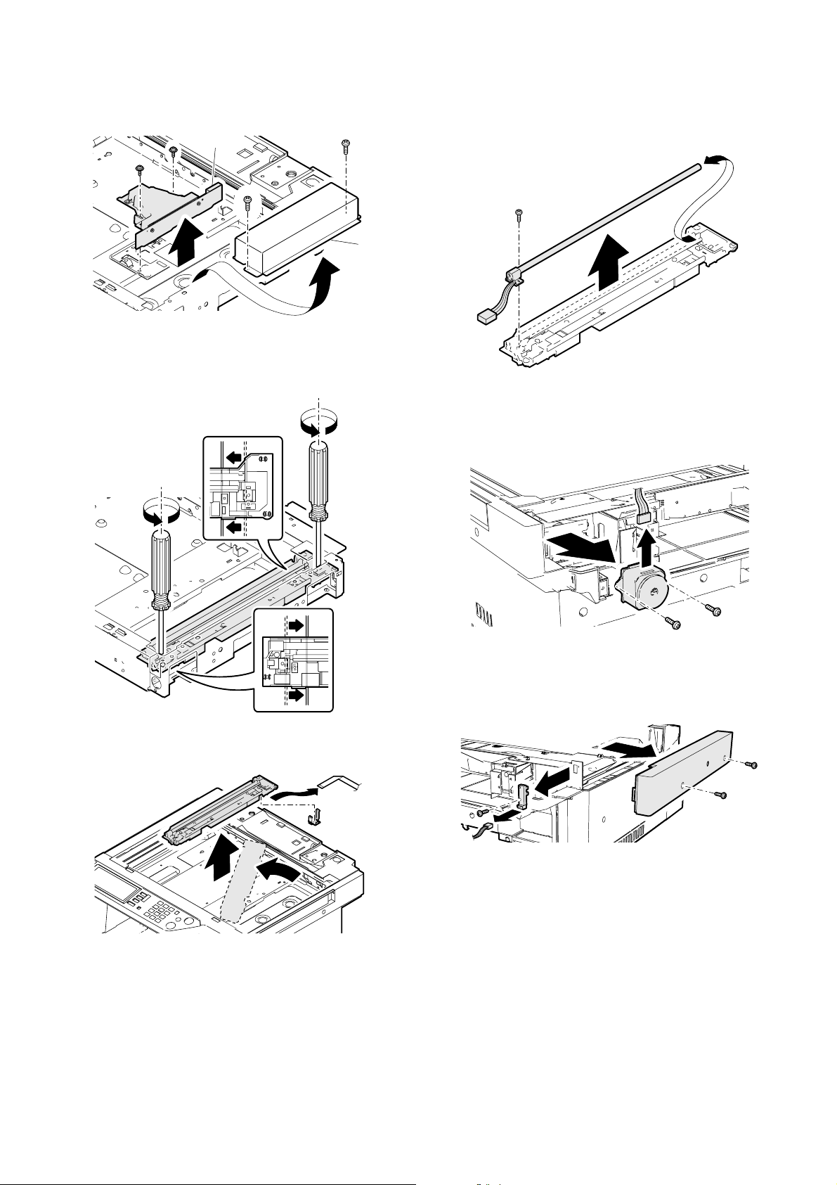
2) Remove the screw and the dark box cover (A). Remove the connector, the screw, and the CCD unit (B).
B
A
c. Lamp unit
1) Shift the lamp unit to the position shown below. Loosen the screw
and remove the wire.
d. Xenon lamp
1) Remove the lamp unit.
2) Remove the harness and the screw, and remove the Xenon lamp.
e. Scanner motor
1) Remove the upper cabinet rear unit.
2) Remove the connector, the screw, and the belt. Remove the
motor.
2) Rotate the lamp unit and lift it, and remove the harness holder and
the harness. Remove the lamp unit.
f. MHPS
1) Remove the upper cabinet rear unit.
2) Remove the screw and remove the upper cabinet left. Remove the
screw and the connector, and remove the MHPS.
AR-C260/C260M DESCRIPTIONS OF EACH SECTION 7 - 26
Page 58
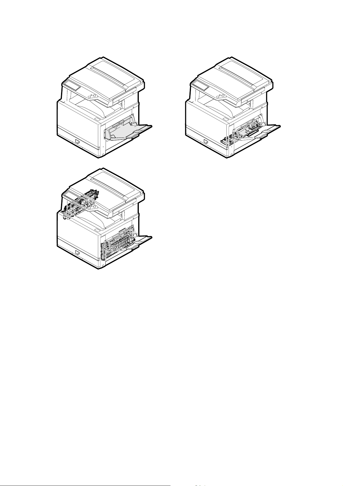
5. Paper feed, paper transport, and paper exit sections
A. Operational descriptions
(1) Outline
This model is provided with a cassette paper feed tray and a manual
paper feed tray as standard provision.
As an option, either the 3-stage paper feed cassette module (AR-D18)
or the 2-stage duplex paper feed cassette module (AR-D19) can be
installed.
The paper transport section transports paper from each paper feed
port to the PS roller section.
Paper with images transferred on it in the transfer section is passed to
the fusing section, and discharged to the face-up tray or the face-down
tray.
AR-C260/C260M DESCRIPTIONS OF EACH SECTION 7 - 27
Page 59

(2) Electrical section and mechanical section
TFD2
PFM
PPD2
TRC
a. Cassette paper feed, paper transport, and paper exit sections
2
6
11
9
7
5
3
1
20
18
16
22
17
15
13
GND2
TFD
+5V
+5V
GND2
POD2
+5V
OFFSETMB\
OFFSETMA\
OFFSETMB
CN20(22pin)
OFFSETMA
+24V
+5V
HPOS\
GND2
PSMB\
1
GND2
POD1
CN14(10pin)
CN13(6pin)
PSMA\
PSMB
PSMA
+24V
+24V
65432
+24V
11
TRC\
13
+24V
1
GND2
3
\DC_LOCK
\DCONOFF
7
5
7
5
PCU
DC_CLK
2
TFD2
GND2
CN11(34pin)
DSWRout
DSWR
+5V
30342527292426
2
3
+5V
GSS\
CN7(32pin)
PPD1
GND2
1
+24V
+5V
PFD1
GND2
28
18
LUD1
C1SS1
16
20
PED1
C1SS2
18
23
+5V
C1SS3
20
19
+24V
CN9(24pin)
GND2
C1SS4
15
22
17
CPFC1\
LUM1b
17
11
GND2
LUM1a
+5V
19
16
PPD2
21
15
PPD2POW
C1PD1
23
18pin
4
GND2
7
HPOS
+5V
8
2
1
7
8pin
PPD1
8
5
13
+24V
OSMA
141415
OSMB
OSMA\
OSMB\
1
2
3
101011
+5V
TFD
12
GND2
+24V
GND2
1
\DC_LOCK
\DCONOFF
3
2
DC_CLK
4
5
16
GND2
POD2
+5V
TRC
PFM
PPD2
PSM
+5V
2
1
2
6
3
7
PPD1
PED1
3
GND2
1
+5V
4
5
PFD1
3
PFD1
CPFC1
6
GND2
2
1
3
2
1
C1SS1
C1SS2
Lift-up PWB
24pin
LUM1
PPD2POW
321
3
2
1
32132121
4
C1SS3
15
PPD2
C1SS4
GND2
LUM1b
16
11
GND2
5
1
7
LUM1b
LUM1a
3
17
CPFC1\
8
LUM1a
+5V
19
+24V
9
15
C1PD1
23
+5V
20
PED1
18
LUD1
LUD1
3
TFD
2
TFD2
5
+24V
4
OSMA
3
OSMB
POD2
2
OSMA\
OSMB\
GSS
POD1
2
3
1
POD2
+5V
1
GND2
1
GND2
2
TFD2
+5V
2
3
GSS\
+24V
2
3
1
1
5pin
54321
Drawer connector
(In the fusing unit)
+5V
POD1
GND2
B6
B1
B4
B3
B5
B2
OSM
HPOS
6
2
3
1
1
GND2
HPOS
+5V
(NC)
AR-C260/C260M DESCRIPTIONS OF EACH SECTION 7 - 28
Page 60
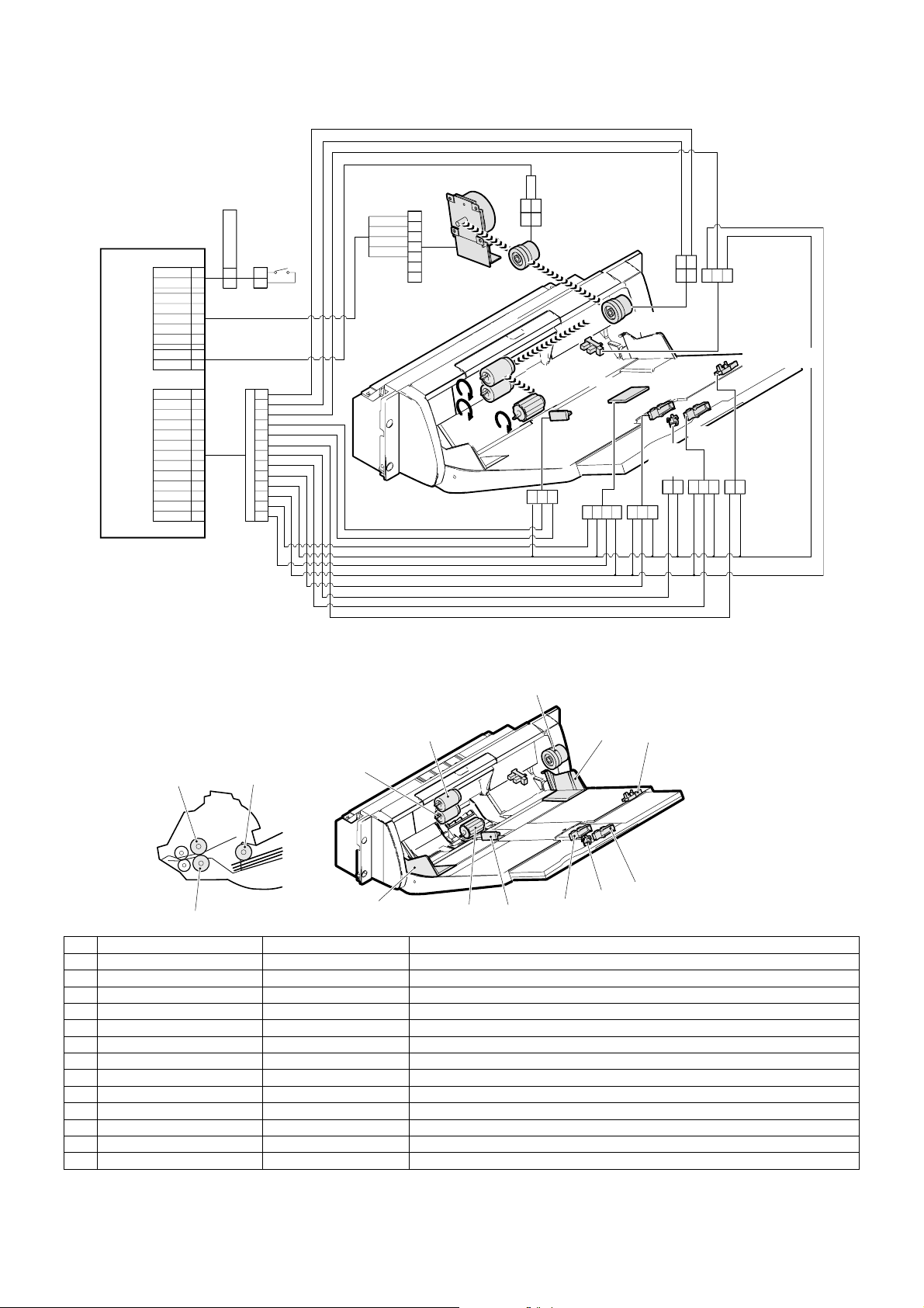
b. Manual paper feed section
MPLD2
MPLD1
34
DSWRout
30
DSWR
1
+24V
3
GND2
CN11(34pin)
PCU
CN17(28pin)
DC_ONOFF\
DC_LOCK\
DC_CLK
+24V
MTRC\
MPFC\
+24V
MPED
MPWSin
+3.3V
MTOP2
MTOP1
MPLD2
MPLD1
GND2
+5V
TEMP_AN
HUMiD_AN
5
7
2
13
14
25
23
17
21
19
22
20
18
16
24
28
15
11
(8pin)
Right door switch
7
8
(14pin)
(2pin)
MTRC\
+24V
3
+24V
1
GND2
2
DC_ONOFF\
3
DC_LOCK\
4
DC_CLK
DSWR
1
2
11
9
3
7
5
8
6
4
2
10
14
13
12
5
6
7
Paper feed motor
PFM
1
1
3
Manual transport clutch
MTRC
MPED
Humidity sensor
MPWS
Paper width
sensor
3
2
1
GND2
+3.3V
MPWSin
4
TEMP
MPFC
Manual paper feed clutch
HUD
Tray position
detection
switch 1
1
33
2
2
GND2
+5V
HUD
MPLD1
+5V
+24V
MPFC\
1
2
GND2
+5V
MPED
1
3
2
1
2
Paper length
sensor 1
MPLD1
MTOP1
1
22
GND2
MTOP1
GND2
MPLD2
Paper length
sensor 2
3
2
GND2
+5V
MPLD2
MTOP2
111
GND2
MTOP2
Tray position
detection switch 2
(3) Major parts and signals functions and operations
a. Manual paper feed unit
9
8
87
10
10
1
72
No. Name Code, Signal name Function
RW Paper detector MPED Detects paper empty/presence in the paper tray.
1 Paper size (width) adjuster — Adjusts the paper position.
2 Paper size (width) sensor MPWS Detects the paper width.
3 Paper size (length) detector MPLD1 Detects the paper length.
4 Paper size (length) detector MPLD2 Detects the paper length.
5 Tray position detector MTOP1 Detects the paper tray position.
6 Tray position detector MTOP2 Detects the paper tray position.
7 Paper pickup roller — Sends paper to the paper feed roller.
8 Manual paper feed roller — Feeds paper to the paper transport section.
9 Manual paper feed clutch MPFC Transmits the paper feed drive motor power to the manual paper feed roller.
10 Separation roller — Separates paper and transmits it to the paper feed unit.
RW Manual transport clutch — Transmits the paper feed motor power to the manual paper feed unit.
RW Paper feed motor — Drives the paper feed section and the manual paper feed unit.
RW: Abbreviation of Related Wiring, which means the said load is specified in the related figure of the mechanical and the electrical sections.
3
1
5
6
4
AR-C260/C260M DESCRIPTIONS OF EACH SECTION 7 - 29
Page 61
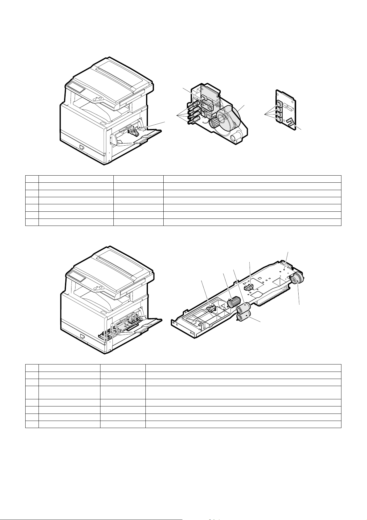
b. Paper tray lift unit
3
4
2
5
1
6
No. Name Code, Signal name Function
1 Paper tray lift unit — Drives the paper tray lift plate.
2 Paper size detection actuator — Transmits the status data (âöìþ) of the paper size block to the paper size detector.
3 Paper tray lift unit control PWB — Controls the paper tray lift unit.
4 Lift motor LUMx Drives the lift plate.
5 Paper size detector (switch) CxSSx Detects the paper size set by the paper size set block.
6 Lift position sensor CxPDx Detects the lift plate position.
c. Paper feed unit
1
2B
5
3
2A
4
6
No. Name Code, Signal name Function
1 Paper tray paper feed unit — Feeds paper from the paper tray to the transport section.
2A Paper empty detector PEDx Detects paper empty in the paper tray.
2B Paper upper limit detector LUDx Detects the paper upper limit position. (Keeps the friction between the paper pickup roller
3 Paper pickup roller — Feeds paper to the paper feed roller.
4 Paper feed clutch CPFCx Controls ON/OFF of the paper feed roller.
5 Paper feed roller — Feeds paper to the paper transport section.
6 Separation roller — Separates paper to prevent against double feed.
AR-C260/C260M DESCRIPTIONS OF EACH SECTION 7 - 30
and paper at a constant level.)
Page 62
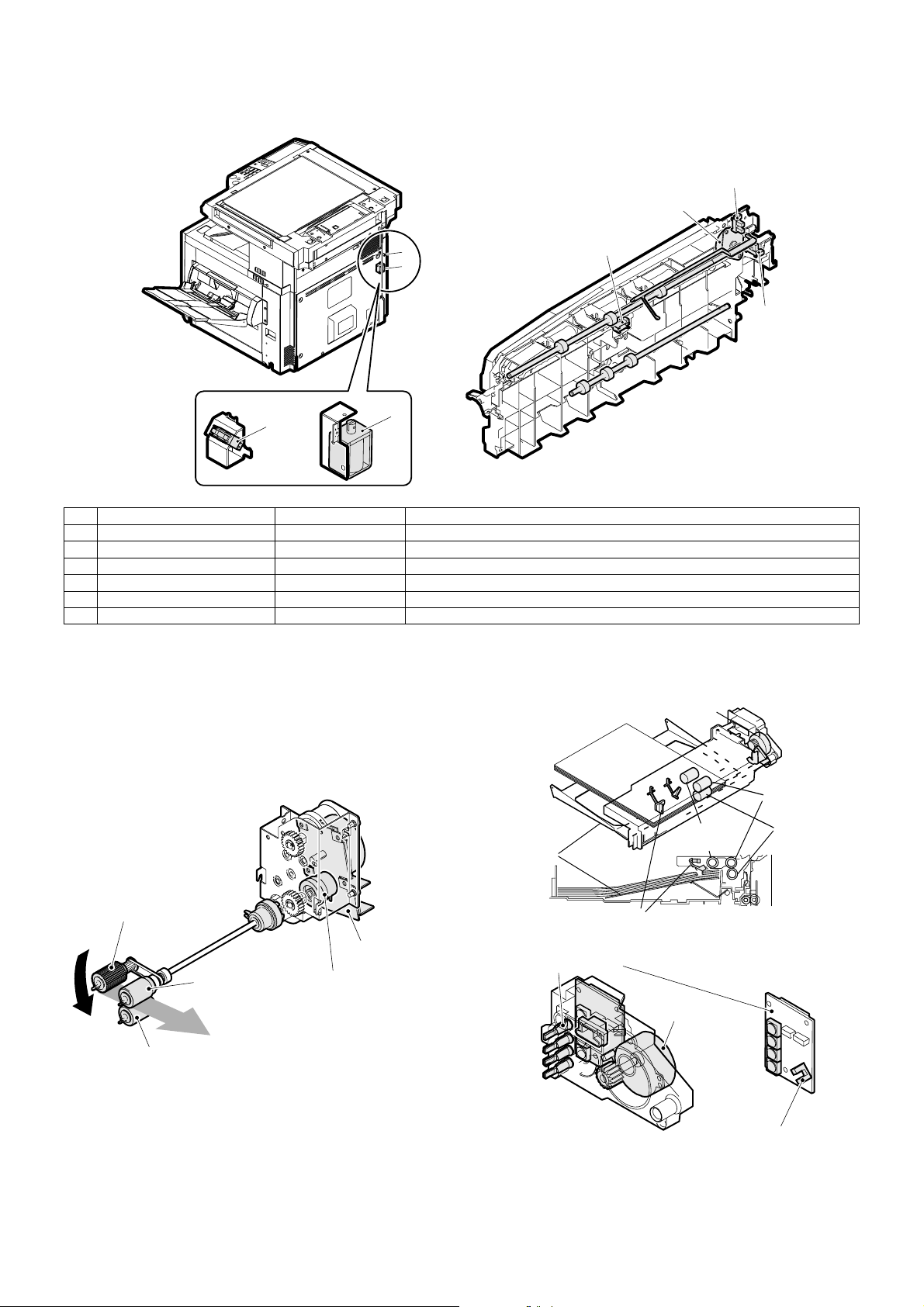
d. Paper exit section
r
3
2
6
1
5
6
No. Name Code, Signal name Function
1 Paper exit sensor POD2 Detects discharged paper.
2 Offset motor OSM Drives the paper exit offset.
3 Shifter home position sensor HPOS Detects the offset home position.
4 FD paper exit full sensor TFD Detects the face-down paper exit tray full.
5 Paper exit switch gate solenoid GSS Drives the face-up/down switch gate.
6 FU paper exit full sensor
5
(4) Operational descriptions
a. Paper feed tray section operation
The paper pickup roller moves up and down to press paper and separates the top paper, which is fed to the paper feed roller.
The paper feed roller feeds paper to the paper transport section. The
separation roller prevents against double feed.
Up and down movement of the pickup roller is driven by the pickup
solenoid, and ON/OFF control of the pickup roller and the paper feed
roller is performed by the paper feed clutch.
The lift position is detected by the paper upper limit detector to control
the pressure between the top paper and the pickup roller.
Lift plate
Lift motor
Pickup
roller
4
Paper feed
rollers
Separation
rollers
Pickup roller
Paper feed motor
Paper feed roller
Separation roller
The paper lift plate lifts paper to control the upper limit position of paper
so that the pressure between the top paper and the pickups roller
remains constant. Lifting is performed by the lift motor and the lift gear.
Paper feed clutch
AR-C260/C260M DESCRIPTIONS OF EACH SECTION 7 - 31
Upper limit detectors
Paper size detector
Lift motor
Lift position senso
Page 63
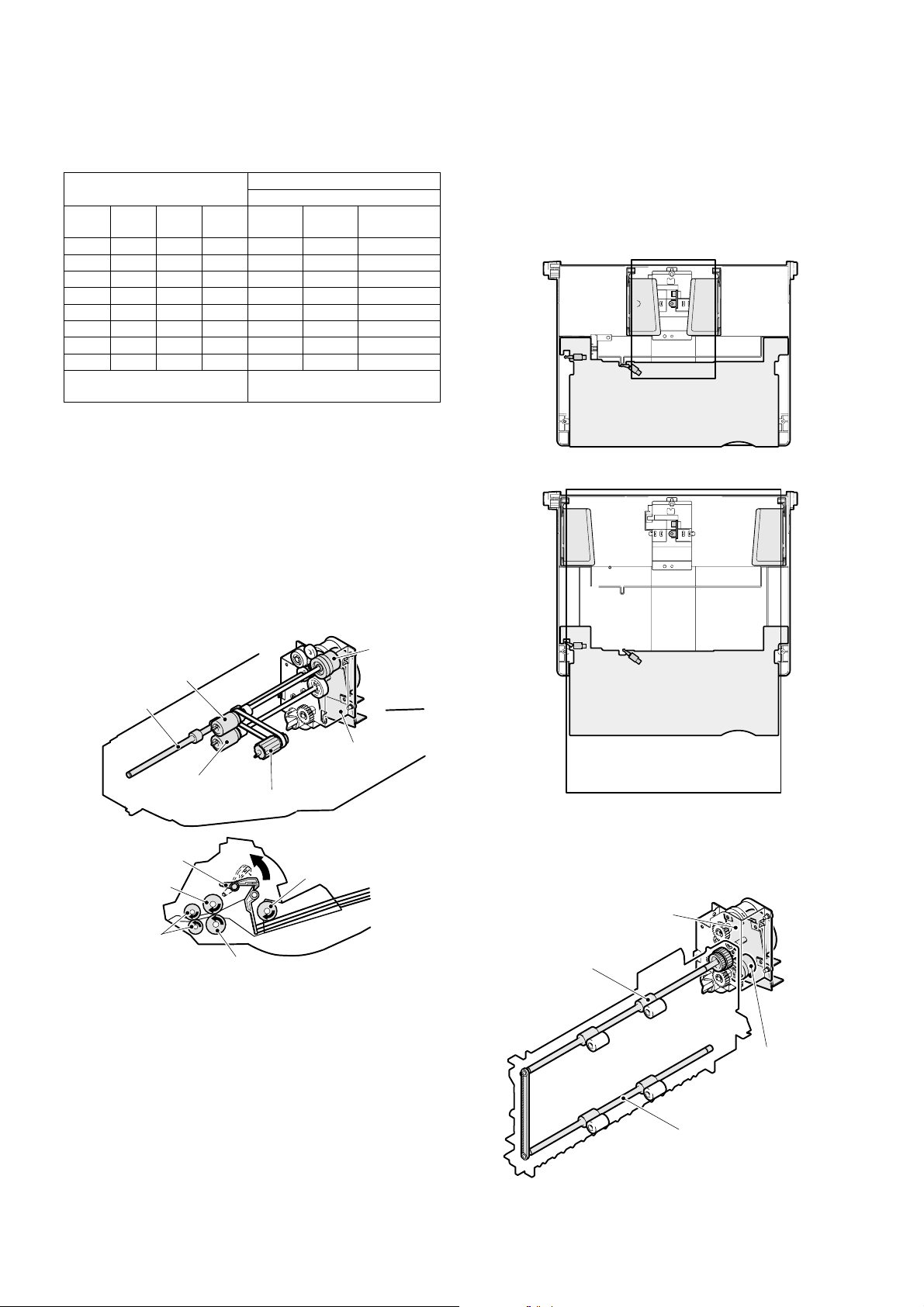
The paper feed tray is provided with the paper size detection block,
and the status (âöìþ) of this block is detected with the combination of
ON/OFF of the four paper size detectors to recognize the paper size.
Relationship between the paper size detector and the paper size
Paper size detector
CSS4 CSS3 CSS2 CSS1 Japan
ON OFF OFF ON A3 A3 11 x 17
OFF OFF ON ON B4 B4 8.5 x 14
ON OFF ON OFF A4R A4R 11 x 8.5R
OFF ON ON OFF A4 A4 11 x 8.5
OFF ON ON ON B5R B5 INVOICE
OFF ON OFF ON B5 A5 FOOLSCAP
ON ON ON OFF A5 11 x 8.5 A4
ON ON OFF OFF EXTRA EXTRA EXTRA
Patterns other than above Recognized that the paper tray is
EXTRA: Operates with the paper size set by the user program.
The lift position sensor detects the lift plate lower limit position. Then
lift-up operation is started, and the rotation of the lift motor up to detection of the upper limit by the paper upper limit detector is used to calculate the paper remaining quantity.
b. Manual paper feed section operation
The paper pickup roller moves up and down to press paper and separates the top paper, which is fed to the paper feed roller.
The paper feed roller feeds paper to the paper transport section. The
separation roller prevents against double feed.
The manual paper feed clutch controls ON/OFF of the pickup roller and
the paper feed roller.
The manual transport roller transports paper to the resist roller.
Paper size
Destination
AB
series
not inserted.
Inch series
The paper size is detected by the paper length detector and the paper
width sensor.
A volume-type sensor is used as the paper width sensor. The resistance varies according to variation of the paper guide position to detect
the paper width.
The tray position detector detects that the paper tray is set to the maximum length position or to the minimum length position.
When the paper tray is set to the maximum length position, the paper
length detector is forcibly turned ON. This is to recognize it.
Paper feed roller
Transport roller
Separation roller
Paper stopper
Paper feed roller
Transport roller
Pickup roller
Separation roller
Paper feed motor
Pickup roller
Clutch
c. Paper transport section
This section transports paper from each paper feed section to the
transfer section (resist roller) by two transport rollers.
The paper transport clutch controls ON/OFF of each transport roller.
Paper feed motor
Paper transport roller
Paper feed clutch
AR-C260/C260M DESCRIPTIONS OF EACH SECTION 7 - 32
Paper transport roller
Page 64

d. Paper resist section
The resist roller controls the relative position of the transported paper
and the transfer image.
The resist roller is driven by the resist roller motor.
The relative position of paper and the transfer image is determined by
e. Others
∗ The paper transport section is provided with two paper detectors,
which perform the following functions:
1) Paper jam detection
2) Output of the reference signal for the operating timing of each load
the ON timing of the resist roller motor.
PS motor
Upper resist roller
Lower resist roller
B. Disassembly/assembly/maintenance
(1) Paper feed/transport sections maintenance target parts
✕: Check (Clean, replace, or adjust as necessary.) ❍: Clean ▲: Replace ∆: Adjust ✩: Lubricate ❏: Shift position
Unit name No. Part name
Paper feed
section
1 Paper feed rollers in the
cassette section
2 Torque limiter
3 Paper feed rollers in the
manual paper feed
section
4 Torque limiter
Transport
section
5 Transport rollers
6 Transport paper guide
When
calling
50K 100K 150K 200K 250K 300K 350K 400K Remark
❍ ❍✕❍✕❍✕❍✕
✕ ✕✕✕✕
❍ ✕✕✕✕✕✕✕✕
✕ ✕✕✕✕✕✕✕✕
❍ ❍❍❍❍❍❍❍❍
❍ ❍❍❍❍❍❍❍❍
Replace at the specified
count at each paper feed
port or within 2 years.
Replace at the specified
count at each paper feed
port or within 2 years.
4
2
1
1
4
3
3
2
1
4
3
5
5
5
6
6
5
3
6
6
AR-C260/C260M DESCRIPTIONS OF EACH SECTION 7 - 33
Page 65

(2) Maintenance parts and major parts replacement
a. Cassette paper feed
<1> Pickup roller
1) Remove the cassette.
2) Disengage the pawl, and remove the pickup roller.
<3> Paper separation roller, torque limiter
1) Remove the cassette.
2) Disengage the pawl, and remove the paper separation roller.
<4> Cassette paper feed unit
1) Open the front cabinet, and remove the drum unit.
Note: Do not remove the transfer belt unit.
<2> Paper feed roller, torque limiter
1) Remove the cassette.
2) Disengage the pawl, and remove the paper feed roller.
2) Remove the developing unit.
AR-C260/C260M DESCRIPTIONS OF EACH SECTION 7 - 34
Page 66

3) Remove the front cabinet and the front frame cover.
4) Remove the multi manual paper feed unit.
5) Remove the connection right cabinet, the rear cabinet, and the rear
right cabinet.
6) Remove the screw and the paper feed unit. Remove the connector.
∗ When assembling, fit the positioning pin A with section C.
C
b. Multi manual paper feed
<1> Pickup roller
1) Open the arm cover (A). Disengage the pawl, and remove the
pickup roller (B).
B
A
A
<5> Paper feed drive motor
1) Remove the screw, the rear cabinet, the rear right cabinet, and the
connection right cabinet B.
2) Remove the screw, and remove the paper feed drive motor.
<6> Paper feed drive unit
1) Remove the harness and the screw, and remove the paper feed
drive unit.
<2> Paper feed roller
1) Open the arm cover (A), open the auxiliary PG (B), and remove the
paper feed roller (C).
A
C
B
<3> Paper separation roller
1) Open the vertical transport guide.
2) Open the maintenance cover (A) from the bottom of the multi
paper feed unit. Disengage the pawl and remove the paper feed
separation roller (B).
AR-C260/C260M DESCRIPTIONS OF EACH SECTION 7 - 35
B
A
Page 67

<4> Multi manual paper feed unit
1) Remove the screw and the harness, and remove the multi paper
feed unit.
2) Remove the screw, and remove (A) and (B).
∗ When assembling, first attach (A), then attach (C) and (D).
B
A
C
D
<5> Paper feed clutch
1) Remove the screw and the cover (A). Remove the connector and
the E-ring, and remove the paper feed clutch (B).
B
A
<6> Transport roller
1) Remove the bottom lid (A), remove the connector and the screw,
and remove the cover (B).
D
C
E
3) Remove the screw and the E-ring, and remove the angle (A) and
the gear.
A
4) Remove the screw, and remove (A) and the manual upper unit (B).
B
B
A
∗ When assembling, fit the cover projection with the spring.
AR-C260/C260M DESCRIPTIONS OF EACH SECTION 7 - 36
A
5) Remove the E-ring, the gear, and the bearing, and remove the
transport roller.
Page 68

c. Transport section
<1> Vertical transport unit
1) Remove the drum and the developing unit.
2) Remove the front cabinet.
3) Remove the front frame cover.
4) Remove the multi manual paper feed unit.
5) Remove the rear cabinet, the connection right cabinet, the rear
right cabinet, the front right cabinet, and the right lower cabinet.
6) Open the vertical transport guide. Remove the screw and remove
the vertical transport guide unit.
7) Remove the screw, and remove the vertical transport lower unit.
<2> Transport roller 2
1) Remove the vertical transport unit.
2) Remove the screw, and remove the paper guide (A).
3) Remove the resin ring, and remove the pulley (B) from the belt.
4) Remove the resin E-ring, slide the bearing (C), and remove the
transport roller 2 unit (D).
C
D
A
B
5) Remove the E-ring and parts, and remove the transport rollers.
8) Remove the paper feed drive motor, and remove the connector on
the rear side. Remove the screw, and shift the vertical transport
unit to the left to remove.
∗ When assembling, engage the four bosses indicated with in
the figure below.
<3> Transport roller 1
1) Remove the vertical transport unit.
2) Remove the resin ring. Remove the pulley (A) from the belt.
3) Remove the resin E-ring, slide the bearing (B), and remove the
transport roller 1 (C).
B
C
A
AR-C260/C260M DESCRIPTIONS OF EACH SECTION 7 - 37
Page 69

<4> PS unit
1) Remove the vertical transport unit.
2) Remove the screw and the spring. Release the lock. Remove the
belt and remove the PS unit.
∗ When assembling, attach from the left with avoiding the plate in
section A.
A
<5> Upper resist roller
1) Remove the vertical transport unit.
2) Remove the PS unit.
3) Remove the spring (A), and remove the upper resist roller (B).
<7> PS motor
1) Remove the rear cabinet, the connection right cabinet, and the rear
right cabinet.
2) Remove the connector and the screw, and remove the process
exhaust fan unit. Remove the connector and the screw, and
remove the PS motor.
d. Paper exit section
<1> Slide drive motor
1) Open the left cabinet.
2) Remove the FD connection cabinet.
3) Remove the connector and the screw, and remove the motor unit.
B
A
<6> Lower resist roller
1) Remove the vertical transport unit.
2) Remove the PS unit.
3) Remove the upper resist roller.
4) Remove the parts and remove the lower resist roller.
A
A
4) Remove the connector and the screw, and remove the motor (A).
AR-C260/C260M DESCRIPTIONS OF EACH SECTION 7 - 38
Page 70

<2> FD paper exit unit
1) Remove the rear cabinet, the rear cabinet upper, the left cabinet,
the rear left cabinet lid, the rear left cabinet, and the front cabinet
upper.
2) Remove the motor unit.
3) Slide section (A) to the front side. Remove the screw, and disengage the pawl in section (B). Remove the FD paper exit unit (C)
from the rear side and remove the connector.
∗ When assembling, attach from the front side.
∗ When assembling, be careful not to damage the actuator (D).
3) Remove the E-ring, (A), the screw, (B), (C), and the bearing.
Remove the unit (D).
D
C
B
B
A
D
C
<3> FD paper exit roller B
1) Remove the cabinet.
2) Remove the paper exit unit.
3) Remove the E-ring, the bearing, and the gear. Remove the FD
paper exit roller.
A
4) Remove the E-ring and the bearing, and remove the FD paper exit
roller (A).
e. Gate solenoid unit
1) Open the left door, and remove the rear cabinet and the rear left
cabinet.
2) Remove the driver PWB unit.
3) Remove the connector and the screw, and remove the gate solenoid unit.
<4> FD paper exit roller A
1) Remove the cabinet.
2) Remove the paper exit unit.
f. Lift-up unit
1) Remove the rear cabinet and the rear right cabinet.
2) Remove the power PWB unit.
3) Remove the connector and the screw, and remove the lift-up unit.
AR-C260/C260M DESCRIPTIONS OF EACH SECTION 7 - 39
Page 71

6. Operation panel
(2) Electrical section and mechanical section
A. Operational descriptions
(1) Outline
The operation panel unit is composed of the operation key PWB, the
inverter/LVDS PWB, the LCD unit, and the operation keys, and is used
to operate the machine and to set and display the machine status.
The operation key PWB is connected to the ORS light receiving PWB
for detecting the document size. It receives light from the ORS light
emitting PWB attached to the rear frame, detecting the document size.
CN4 (20pin) CN1 (30pin)CN3 (2pin)
1
Vss (GND2)
2
NC
3
NC
4
NC
5
NC
6
Vss (GND2)
7
LCD_D3
8
LCD_D2
9
LCD_D1
10
LCD_D0
11
Vss (GND2)
12
LCD-VEE
13
3.3V
14
LCD-DIS
15
Vss (GND2)
16
LCD-CP2
17
Vss (GND2)
18
LCD_CP1
19
LCD_M
20
LCD_S
FLS
CN2 (5pin)
1
/YL
2
XH
3
YH
4
/XL
FM
Inverter/LVDS PWB
Operation panel unit
LCD unit
21
BHHV/CCFT
LCDS+
LCDS-
LCDM+
LCDM-
LCDCP1+
LCDCP1-
GND2
LCDCP2+
LCDCP2-
GND2
LCDDIS
LCD-VCC
LCD-VEE
LCDD0+
LCDD0-
LCDD1+
LCDD1-
LCDD2+
LCDD2-
LCDD3+
LCDD3-
GND2
TH
GND2
+24V
/CCFT
YH
/XL
/YL
XH
FMZ
1
2
3
4
5
6
7
8
9
10
11
12
13
14
15
16
17
18
19
20
21
22
23
24
25
26
27
28
29
30
Touch panel
LCD
Backlight
CN2 (6pin) CN1 (26pin)
1
2
3
4
5
6
PDSEL0
PDSEL1
PDSEL2
+5V
PD
GND2
PH
Operation key PWB
ORS light
receiving PWB
1
GND2
2
SCAN0
3
SCAN1
4
SCAN2
5
SCAN3
6
SCAN4
7
SENSE0
8
SENSE1
9
SENSE2
10
SENSE3
11
SENSE4
12
SEG0\
13
SEG1\
14
SEG2\
15
SEG3\
16
COM0
17
COM1
18
COM2
19
FRDY
20
/BZR
21
PDSEL0
22
PDSEL1
23
PDSEL2
24
+5V
25
PD
26
GND2
FAZ
ORS light
emitting PWB
OCSW
CN3 (30pin)
Document size detection
MFP PWB
CN6 (6pin)CN5 (26pin)
GND23OCSW4+24V5/LED06/LED1
+5V
21
(3) major parts functions and operations
No. Name Code, signal name Function
RW Operation key PWB — Detects a pressed key on the operation panel.
RW Inverter/LVDS PWB — Drives the LCD and the backlight, and controls the touch panel.
RW ORS light receiving PWB — Receives light from the ORS light emitting PWB to detect the document size.
RW ORS light emitting PWB — Emits light for detecting the document size.
RW OC switch OCSW Timing switch for detecting the document size
RW: Abbreviation of Related Wiring, which means the said load is specified in the related figure of the mechanical and the electrical sections.
AR-C260/C260M DESCRIPTIONS OF EACH SECTION 7 - 40
Page 72

B. Disassembly/assembly/maintenance
a. ORS light emitting PWB
1) Remove the upper cabinet rear cover and the upper cabinet rear
unit.
2) Remove the screw, and remove the document size sensor unit.
Remove the screw and the document size sensor, and remove the
ORS light emitting PWB.
d. Operation key PWB
1) Remove the FD connection cabinet, the front cabinet upper, the
FD paper exit port cabinet, and the operation panel plate.
2) Remove the screw, and remove A and B.
3) Remove the screw and the connector, and remove the operation
unit.
A
B
b. OCSW
1) Remove the upper cabinet rear cover and the upper cabinet rear
unit.
2) Remove the connector and the screw, and remove the OCSW.
c. ORS light receiving PWB
1) Remove the FD connection cabinet, the front cabinet upper, the
FD paper exit port cabinet, and the operation panel plate.
2) Remove the connector and the screw, and remove the ORS light
receiving PWB.
4) Remove the screw and remove the operation key PWB.
e. Inverter/LVDS PWB
1) Remove the FD connection cabinet, the front cabinet upper, the
FD paper exit port cabinet, and the operation panel plate.
2) Remove the connector and the screw, and remove the inverter/
LVDS PWB.
AR-C260/C260M DESCRIPTIONS OF EACH SECTION 7 - 41
Page 73

7. External fitting
A. Disassembly
(1) Cabinet disassembly 1
1) Open the front cabinet.
2) Remove the front cabinet band. Pull out the slide pin (B), and
remove the front cabinet (C).
(4) Cabinet disassembly 4
1) Remove the screw, and remove the rear cabinet (A). Remove the
screw, and remove the DC power CFM unit (B) and the connector.
Remove the screw, and remove the ROM cover (C) and the rear
connection cabinet (D).
∗ When assembling, insert the boss in section E into the hole in
the frame.
B
A
B
A
C
(2) Cabinet disassembly 2
1) Remove the front cabinet.
2) Open the left cabinet. Remove the screw and remove the front
frame cover.
D
C
A
B
E
(5) Cabinet disassembly 5
1) Remove the rear cabinet.
2) Remove the screw (A), and slide the front right cabinet (B) upward
to remove. Remove the screw, and slide the connection right cabinet (C), the rear right cabinet (D), and the right lower cabinet (E)
upward to remove.
A
B
C
(3) Cabinet disassembly 3
1) Remove the screw, and slide the paper exit tray cabinet right to the
right to remove.
E
D
(6) Cabinet disassembly 6
1) Remove the rear cabinet.
2) Remove the screw, and remove the FD connection cabinet (A) and
the front cabinet upper (B). Remove the screw, and slide the rear
left cabinet lid (C) and the rear left cabinet (D) upper to remove.
C
D
A
B
AR-C260/C260M DESCRIPTIONS OF EACH SECTION 7 - 42
Page 74
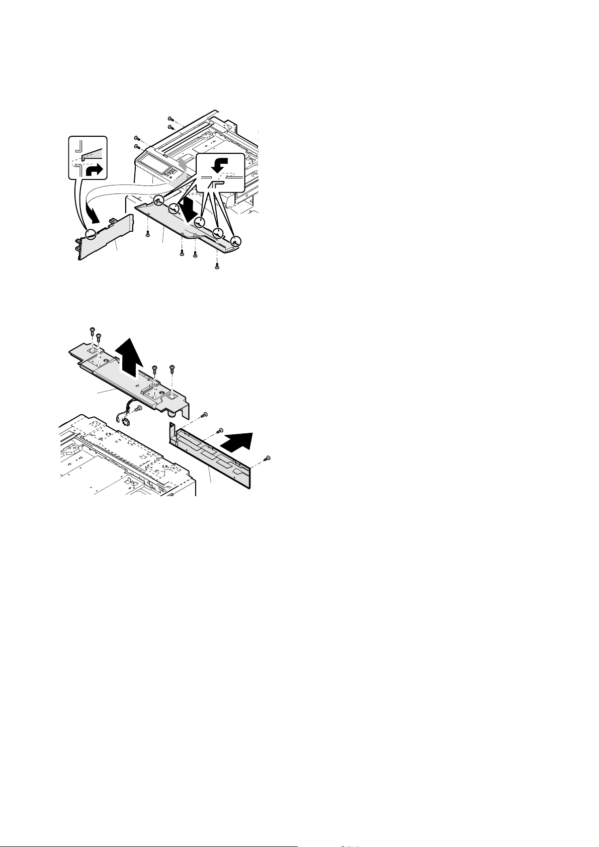
(7) Cabinet disassembly 7
1) Remove the screw, and remove the FD paper exit port cabinet (A)
and the operation panel plate (B).
A
B
(8) Cabinet disassembly 8
1) Remove the screw, and remove the upper cabinet rear cover (A).
Remove the connector and the screw, and remove the upper cabinet rear unit.
B
A
AR-C260/C260M DESCRIPTIONS OF EACH SECTION 7 - 43
Page 75
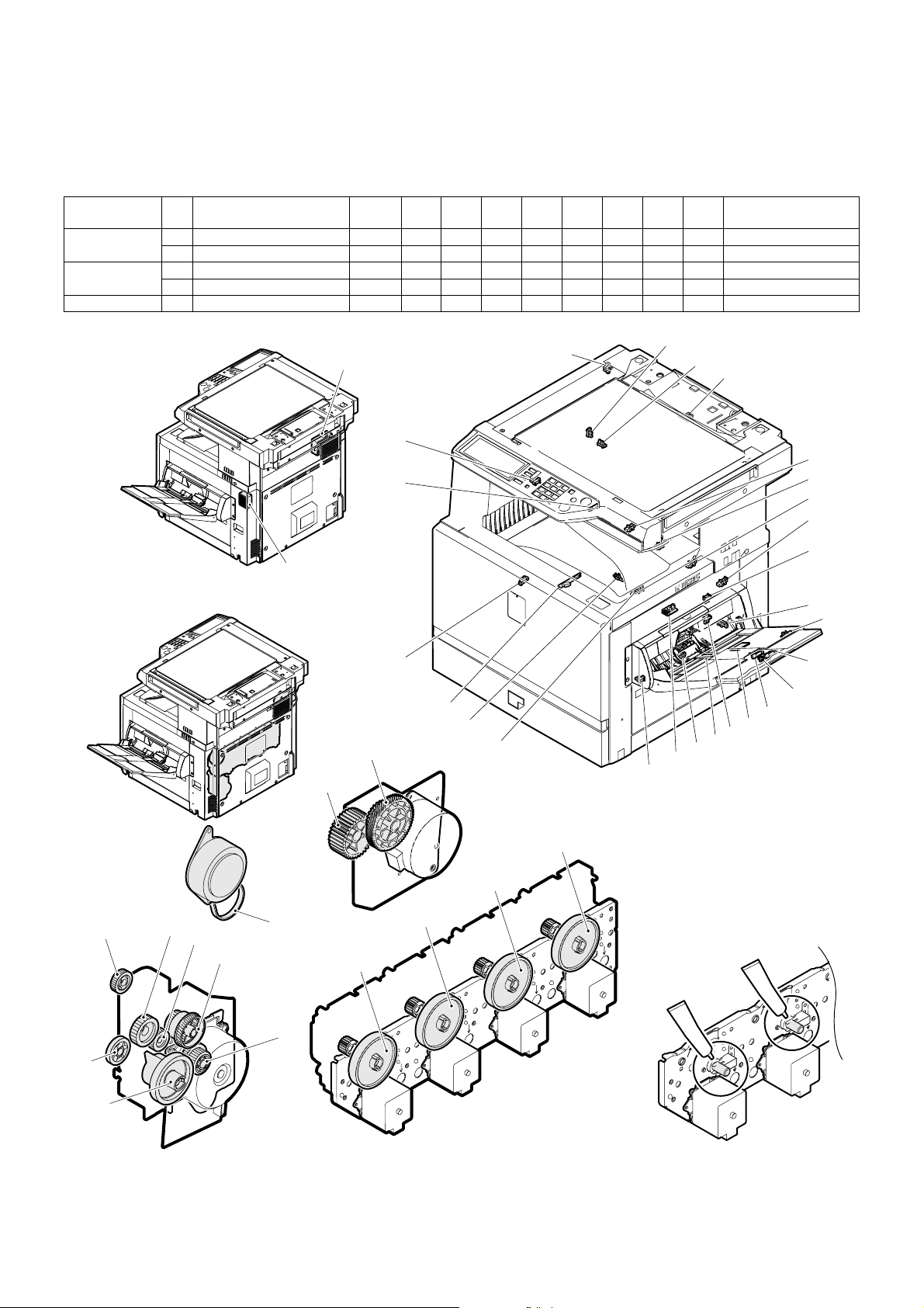
8. Others
A. Disassembly/assembly/maintenance
(1) Maintenance target parts
✕: Check (Clean, replace, or adjust as necessary.) ❍: Clean ▲: Replace ∆: Adjust ✩: Lubricate ❏: Shift position
Unit name No. Part name
Filters 1 Ozone filter ✕ ▲▲▲▲▲▲▲▲
2 Sub ozone filter ✕ ▲▲▲▲▲▲▲▲
Drive section 3 Gears ✩ ✩✩✩✩✩✩✩✩
4Belts ✕ ✕✕✕✕✕✕✕✕
Others 5 Sensors ✕ ✕✕✕✕
When
calling
50K 100K 150K 200K 250K 300K 350K 400K Remark
1
5
5
5
5
5
5
5
5
5
5
5
2
5
5
5
5
5
5
5
3
3
5
5
5
5
5
5
5
5
33
3
3
3
3
3
3
4
3
3
3
AR-C260/C260M DESCRIPTIONS OF EACH SECTION 7 - 44
Page 76

(2) Maintenance parts and major parts replacement
a. Ozone filter
1) Remove the ozone filter cover, and remove the ozone filter.
b. Sub ozone filter
1) Remove the sub ozone filter cover, and remove the sub ozone filter.
<3> Power PWB
1) Remove the rear cabinet and the DC power CFM unit.
2) Remove the connector and the screw, and remove the power
PWB.
<4> Driver PWB
1) Remove the rear cabinet, the rear left cabinet lid, and the rear left
cabinet.
2) Remove the screw and the connector, and remove the driver PWB.
c. PWB
<1> PCU PWB
1) Remove the rear cabinet.
2) Remove the connector and the screw, and remove the PCU PWB.
<2> High voltage MC power PWB
1) Remove the rear cabinet.
2) Remove the connector and the screw, and remove the PCU PWB
unit.
3) Remove the connector and the screw, and remove the high voltage MC power PWB.
<5> AC PWB
1) Remove the screw, the rear cabinet, the rear left cabinet lid, and
the rear left cabinet.
2) Remove the screw and the harness, and remove the driver PWB
unit.
3) Remove the harness and remove the AC PWB from the supporter.
AR-C260/C260M DESCRIPTIONS OF EACH SECTION 7 - 45
Page 77
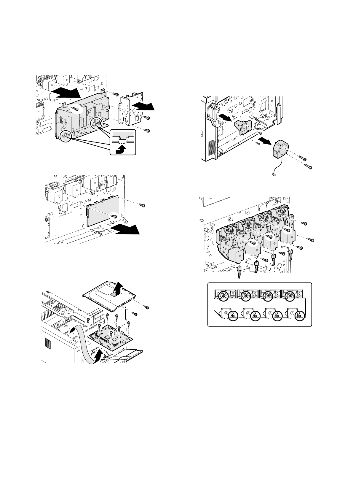
<6> High voltage TC power PWB
1) Remove the rear cabinet, the DC power CFM unit, the rear left
cabinet lid, and the rear left cabinet.
2) Remove the connector, the harness, and the screw. Remove the
Power PWB unit.
3) Remove the connector and the screw, and remove the high voltage TC power PWB.
<8> Drum drive unit
1) Remove the rear cabinet.
2) Remove the DC power CFM unit.
3) Remove the driver PWB unit.
4) Remove the PCU PWB unit.
5) Remove the screw and the connector, and remove the intake duct
FAN.
6) Remove the screw and the intake duct.
7) Remove the high voltage MC PWB.
8) Remove the connector screw and the drum drive unit.
<7> ICU PWB
1) Remove the paper exit tray cabinet right.
2) Remove the screw, and remove the box cover. Remove the screw,
and remove the ICU PWB.
AR-C260/C260M DESCRIPTIONS OF EACH SECTION 7 - 46
Page 78

[8] SETTING AND ADJUSTMENTS
Each adjustment item in the adjustment item list is indicated with its JOB number.
Perform the adjustment procedures in the sequence of Job numbers from the smallest to the greatest.
However, there is no need to perform all the adjustment items. Perform only the necessary adjustments according to the need.
Unnecessary adjustments can be omitted. Even in this case, however, the sequence from the smallest to the greatest JOB number must be observed.
If the above precaution should be neglected, the adjustment would not complete normally or a trouble may occur.
JOB No ADJUSTMENT ITEM LIST SIMULATION
ADJ 1 High voltage adjustment ADJ 1A Main charger grid voltage adjustment 8-2
ADJ 1B DV bias voltage adjustment 8-1
ADJ 1C Transfer voltage adjustment 8-6
ADJ 2 Image density sensor adjustment ADJ 2A Color image density sensor adjustment (adjustment by the
ADJ 2B Black image density sensor adjustment 44-2
ADJ 2C Color image density sensor & black image density sensor
ADJ 3 Image focus, image skew adjustment (LED (writing) unit) 64-1/61-4
ADJ 4 Image registration adjustment ADJ 4A Image registration adjustment (Auto adjustment) 50-22
ADJ 4B Image registration adjustment (Manual adjustment) 50-20
ADJ 5 Image position/print area adjustment
(Print engine section)
ADJ 6 Copy image distortion adjustment ADJ 6A Scanner (reading) unit parallelism adjustment
ADJ 7 Copy image focus (main scanning direction copy magnification ratio) adjustment (CCD unit position adjustment) 48-1
ADJ 8 Sub scanning direction copy magnification ratio adjustment 48-1
ADJ 9 Main scanning direction copy image position adjustment (Scanner (reading) section) 50-12
ADJ 10 Copy image position/image loss/void area adjustment 50-1/50-2
ADJ 11 Copy color balance/density adjustment ADJ 11A CCD gamma adjustment (CCD calibration)
ADJ 12 Fusing pressure adjustment
ADJ 13 Fusing paper guide position adjustment
ADJ 14 Document size sensor adjustment ADJ 14A Original size sensor detection point adjustment 41-2
ADJ 15 Manual paper feed tray paper size sensor adjustment 40-2
ADJ 16 Touch panel coordinates setting 65-1
ADJ 17 Power voltage adjustment ADJ 17A 3.4 V power voltage adjustment
ADJ 18 FAX/scanner mode image loss adjustment 50-27
*1: The simple adjustment does not use the adjustment jig. Its adjustment accuracy may be lower than that of the adjustment by using the adjustment
jig under some machine conditions.
ADJ 5A Main scanning direction image position adjustment
ADJ 5B Sub scanning direction image position/print area adjustment
ADJ 6B Copy image sub scanning direction distortion adjustment
ADJ 6C Copy image main scanning direction distortion adjustment
ADJ 6D Scan image distortion adjustment
ADJ 11B Copy color balance adjustment (Auto adjustment) 46-24
ADJ 11C Copy color balance adjustment (Manual adjustment) 46-21
ADJ 11D Copy density adjustment in low-density area
ADJ 11E Copy color balance density adjustment (each copy mode)
ADJ 11F CCD gamma adjustment (CCD calibration)
ADJ 11G Image edge section gamma/density adjustment
ADJ 11H Copy color balance adjustment (Single color Copy mode)
ADJ 11I Auto color balance adjustment by user (Copy color balance
ADJ 11J Background process conditions setting in the color auto copy
ADJ 14B Original size sensor sensitivity adjustment 41-2
ADJ 17B 5.0 V power voltage adjustment
adjustment jig)
adjustment (Simple adjustment) *1
(Print engine section)
(Print engine section)
(Normal document copy mode)
(Normally unnecessary to adjust.)
(Normally unnecessary to adjust.)
(Copy document copy mode)
(Black text and black line reproduction adjustment) (Normally
unnecessary to adjust.)
(Normally unnecessary to adjust.)
auto adjustment enable setting and adjustment)
mode, image auto recognition conditions setting, text-on-dot
recognition conditions setting
44-13
44-36
50-10
50-5
63-3 (63-5)
46-1/2
46-10 to 16
63-9
46-27
46-25
26-53
46-33
AR-C260/C260M SETTING AND ADJUSTMENTS 8 - 1
Page 79
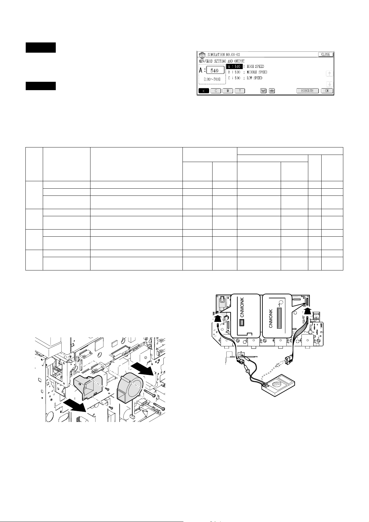
ADJ 1 High voltage adjustment
Since the output voltage cannot be checked directly due to the
machine structure, the adjustment value of the simulation is set to the
default (specified value) to perform the adjustment.
1) Enter the SIM 8-2 mode.
ADJ 1A Main charger grid voltage adjustment
This adjustment must be performed in the following cases:
• When the high voltage power PWB is replaced.
• When a U2 trouble occurs.
• When the PCU PWB is replaced.
• When the EEPROM of the PCU PWB is replaced.
Color Item Operation mode
K A: HIGH SPEED High speed (140mm/s) (B & W) 180 – 700 620 53.5 ± 0.2v CNMONK 1 –620v
B: MIDDLE SPEED Middle speed (117mm/s) (Color) (B & W) 180 – 700 620 53.5 ± 0.2v CNMONK 1 –620v
C: LOW SPEED Low speed (58.5mm/s) (Color) (B & W)
(Special paper)
C A: MIDDLE SPEED Middle speed (117mm/s) (Color) (B & W) 180 – 700 620 53.5 ± 0.2v CNMON 3 –620v
B: LOW SPEED Low speed (58.5mm/s) (Color) (B & W)
(Special paper)
M A: MIDDLE SPEED Middle speed (117mm/s) (Color) (B & W) 180 – 700 620 53.5 ± 0.2v CNMON 7 –620v
B: LOW SPEED Low speed (58.5mm/s) (Color) (B & W)
(Special paper)
Y A: MIDDLE SPEED Middle speed (117mm/s) (Color) (B & W) 180 – 700 620 53.5 ± 0.2v CNMON 11 –620v
B: LOW SPEED Low speed (58.5mm/s) (Color) (B & W)
(Special paper)
Remark: When the default value is set, the specified voltage is output-
ted.
There is, therefore, no need to check the output voltage
unless there is a doubt for any abnormality in the output voltage.
If there is a need to check that the normal voltage is outputted or to adjust by referring to the output voltage, use the
method below.
1) Remove the rear cover of the machine.
2) Remove the image process fan motor and the duct.
2) Select the output mode to be adjusted with the color key and scroll
key.
3) Enter the adjustment value (specified value), and press the [OK]
key.
By entering the default value (specified value), the specified voltage is outputted.
Adjustment value
Adjustment
range
180 – 700 590 50.6 ± 0.2v CNMONK 1 –590v
180 – 700 590 50.6 ± 0.2v CNMON 3 –590v
180 – 700 590 50.6 ± 0.2v CNMON 7 –590v
180 – 700 590 50.6 ± 0.2v CNMON 11 –590v
3) Connect the high voltage adjustment harnesses (DHAi-3471FCZZ/
Specified
value
(Default)
DHAi-3472FCZZ) with the connectors CNMON and CNMONK on
the high voltage PWB.
SIM 8-2
Main charger grid voltage
Monitor (High voltage PWB)
Monitor voltage
(Specified value)
Connector
Pin
No.
Actual
voltage
A
B
4) Enter the SIM8-2 mode.
5) Select the output mode to be adjusted with the color key and the
scroll key.
6) Check that the pin numbers of the connectors CNMON and
CNMONK are properly assigned to the connector pin numbers of
the high voltage adjustment harness.
7) Apply a digital multi-meter to the connector pins of the high voltage
adjustment harness corresponding to the output mode to be
adjusted.
AR-C260/C260M SETTING AND ADJUSTMENTS 8 - 2
Page 80

8) Press the [EXECUTE] key.
The main charger grid voltage is outputted for 30sec.
If this operation is performed for a long time, the OPC drum and
the developing roller may be damaged. Be careful to perform this
operation in a short time.
It is advisable to install an unnecessary developing unit and unnecessary OPC drums to the machine for this adjustment.
9) Check the monitor voltage with the digital multi-meter.
If the monitor voltage is not in the above specified range, change
the adjustment value and adjust again. If the specified voltage is
not obtained even by changing the adjustment value, the following
parts may be judged as defective.
High voltage PWB
PCU PWB
Developing unit
Photoconductor unit
High voltage circuit electrode
Color Item Operation mode
K A: HIGH SPEED High speed (140mm/s) (B & W) 180 – 700 315 7.43 ± 0.1V CNMONK 3 –315v
B: MIDDLE SPEED Middle speed (117mm/s) (Color) (B & W) 180 – 700 315 7.43 ± 0.1V CNMONK 3 – 315v
C: LOW SPEED Low speed (58.5mm/s) (Color) (B & W)
(Special paper)
C A: MIDDLE SPEED Middle speed (117mm/s) (Color) (B & W) 180 – 700 265 5.76 ± 0.1V CNMON 1 –265v
B: LOW SPEED Low speed (58.5mm/s) (Color) (B & W)
(Special paper)
M A: MIDDLE SPEED Middle speed (117mm/s) (Color) (B & W) 180 – 700 265 5.76 ± 0.1V CNMON 5 – 265v
B: LOW SPEED Low speed (58.5mm/s) (Color) (B & W)
(Special paper)
Y A: MIDDLE SPEED Middle speed (117mm/s) (Color) (B & W) 180 – 700 240 4.75 ± 0.1V CNMON 9 – 240v
B: LOW SPEED Low speed (58.5mm/s) (Color) (B & W)
(Special paper)
Remark: When the default value is set, the specified voltage is output-
ted.
There is, therefore, no need to check the output voltage
unless there is a doubt for any abnormality in the output voltage.
If there is a need to check that the normal voltage is outputted or to adjust by referring to the output voltage, use the
method below.
1) Remove the rear cover of the machine.
2) Remove the image process fan motor and the duct.
ADJ 1B DV bias voltage adjustment
This adjustment must be performed in the following cases:
• When the high voltage power PWB is replaced.
• When a U2 trouble occurs.
• When the PCU PWB is replaced.
• When the EEPROM of the PCU PWB is replaced.
1) Enter the SIM 8-1 mode.
SIM 8-1
2) Select the output mode to be adjusted with the color key and the
scroll key.
3) Enter the adjustment value (specified value), and press the [OK]
key.
By entering the default value (specified value), the specified voltage is outputted.
Adjustment value
Adjustment
range
180 – 700 285 6.45 ± 0.1V CNMONK 3 –285v
180 – 700 235 4.75 ± 0.1V CNMON 1 – 235v
180 – 700 235 4.75 ± 0.1V CNMON 5 – 235v
180 – 700 210 3.78 ± 0.1V CNMON 9 – 210v
3) Connect the high voltage adjustment harnesses (DHAi-3471FCZZ/
Specified
value
(Default)
DHAi-3472FCZZ) with the connectors CNMON and CNMONK on
the high voltage PWB.
Monitor (High voltage PWB)
Monitor voltage
(Specified value)
Developing bias voltage
Connector
Pin
No.
Actual
voltage
A
B
4) Enter the SIM8-2 mode.
5) Select the output mode to be adjusted with the color key and the
scroll key.
6) Check that the pin numbers of the connectors CNMON and
CNMONK are properly assigned to the connector pin numbers of
the high voltage adjustment harness.
AR-C260/C260M SETTING AND ADJUSTMENTS 8 - 3
Page 81

7) Apply a digital multi-meter to the connector pins of the high voltage
adjustment harness corresponding to the output mode to be
adjusted.
8) Press the [EXECUTE] key.
The developing bias voltage is outputted for 30sec.
If this operation is performed for a long time, the OPC drum and
the developing roller may be damaged. Be careful to perform this
operation in a short time.
It is advisable to install an unnecessary developing unit and unnecessary OPC drums to the machine for this adjustment.
9) Check the monitor voltage with the digital multi-meter.
If the monitor voltage is not in the above specified range, change
the adjustment value and adjust again. If the specified voltage is
not obtained even by changing the adjustment value, the following
parts may be judged as defective.
High voltage PWB
PCU PWB
Developing unit
Photoconductor unit
High voltage circuit electrode
Item Print mode
A PLAIN_SPX_CL Color Normal paper 117mm/s 173 159 132 132 51 - 255 2.4 2.4 2.4 2.4
B PLAIN_DPX_CL Color Normal paper(Duplex mode) 117mm/s 188 173 142 142 2.7 2.7 2.7 2.7
C OHP1_CL Color Transparency film 1 117mm/s 204 187 153 153 3 3 3 3
D OHP2_CL Color Transparency film 2 58.5mm/s 137 150 153 163 1.7 2.2 3 3.3
E HEAVY P1_SPX_CL Color Thick paper 1 58.5mm/s 158 146 122 122 2.1 2.1 2.1 2.1
F HEAVY_P1_DPX_CL Color Thick paper 1(Duplex mode) 58.5mm/s 188 173 142 142 2.7 2.7 2.7 2.7
G HEAVY_P2_CL Color Thick paper 2 58.5mm/s 173 159 132 132 2.2 2.2 2.2 2.2
H ENV_CL Color Envelope 117mm/s 163 150 125 125 2.2 2.2 2.2 2.2
I PLAIN_SPX_BW B & W Normal paper 140mm/s 168 2.3
J PLAIN_DPX_BW B & W Normal paper(Duplex mode) 140mm/s 178 2.5
K OHP1_BW B & W Transparency film 1 117mm/s 204 3
L OHP2_BW B & W Transparency film 2 58.5mm/s 137 1.7
M HEAVY_P1_SPX_BW B & W Thick paper 1 58.5mm/s 147 1.9
N HEAVY_P1_DPX_BW B & W Thick paper 1(Duplex mode) 58.5mm/s 178 2.5
O HEAVY_P2_BW B & W Thick paper 2 58.5mm/s 163 2.2
P ENV_BW B & W Envelope 140mm/s 168 2.3
ADJ 1C Transfer voltage adjustment
This adjustment must be performed in the following cases:
• When the high voltage power PWB is replaced.
• When a U2 trouble occurs.
• When the PCU PWB is replaced.
• When the EEPROM of the PCU PWB is replaced.
1) Enter the SIM 8-6 mode.
SIM 8-6
2) Select the mode to be adjusted with the color key and scroll key.
3) Enter the adjustment value (specified value), and press the [OK]
key.
By entering the default value (specified value), the specified voltage is outputted.
Standard setting value
(Default)
KCMY KCMY
Adjustment
range
Output voltage (Kv)
Color Actual output variable range Voltage change/Adjustment value (1) (Varying amount when the adjustment value is changed by 1)
K 0 to 4000V About 19.6V
C 0 to 4500V About 22.1V
M 0 to 6000V About 29.4V
Y 0 to 6000V About 29.4V
Press the [EXECUTE] key to output the transfer voltage.
ADJ 2 Image density sensor adjustment
The image density sensor sections are of uneven quality in parts and
assembly. This causes variations in the absolute detection level
between machines. This adjustment (calibration) is performed to correct the variations.
This adjustment is required in the following cases:
• When the image density sensor is replaced.
• When the transfer unit is replaced.
• When maintenance is performed.
• When U2 trouble occurs.
• When the PCU PWB is replaced.
• When the EEPROM on the PCU PWB is repalced.
AR-C260/C260M SETTING AND ADJUSTMENTS 8 - 4
The targets of the adjustment are the color image density sensor and
the black image density sensor. There are following adjustment methods:
• Color image density sensor adjustment (adjustment by the adjustment jig) SIM44-13
• Black image sensity sensor adjustment SIM44-2
• Image density sensor adjustment (The color image density sensor
and the black image density sensor are adjusted at the same time.)
(Simple adjustment) SIM44-36
Normally the following adjustments are executed:
• ADJ 2A Color image density sensor adjustment (adjustment by the
adjustment jig) (SIM44-13)
• ADJ 2B Black image density sensor adjustment (SIM44-2)
Page 82

Note:
There are two methods to adjust the color image density sensor; one
method uses the adjustment jig, and the other method does not use it.
If there is no adjustment jig available, the simple adjustment (SIM44-
36) can be made, which may, however, result in insufficient adjustment
accuracy depending on the machine condition.
If toner, the OPC drum, and the transfer belt are not new ones or
almost new ones, the simple adjustment is not recommended.
Even though the machine conditions are well, the adjustment by use of
the adjustmment jig gives a higher adjustment accuracy than the
adjustment without the adjustment jig (simple adjustment).
Also note that SIM44-36 must not executed unnecessarily after execution of the color image density sensor adjustment (adjustment by the
adjustment jig) with SIM44-13.
If SIM 44-36 is executed, the contents of the color image density sensor adjustment (adjustment by the adjustment jig) with SIM44-13 are
erased, and the adjustment result of SIM44-36 is saved.
When the color image density sensor is adjusted with SIM44-13 and
the black image density sensor is adjsuted with SIM 44-2, the adjustment with SIM44-36 is not required.
To adjust the black image density sensor, the adjustment jig is not
required.
Before executing this adjustment, check the following items:
• Check that the color imagte density sensor is clean.
• Check that the image density sensor calibration plate is clean.
• Check that the transfer belt is free from scratches.
ADJ 2A Color image density sensor adjustment
(adjustment by the adjustment jig)
1) Open the front cover of the machine.
2) Insert the color image density sensor adjustment jig
(CPLTM6305FC01) into the long hole in the transfer unit frame,
and close the left cabinet.
3) With the front cover of the machine open (with the cover open/
close switch OFF), turn on the power.
4) The Machine enters Sim 44-13 mode.
SIM 44-13
5) Close the front cover of the machine.
6) Press the [EXECUTE] key.
The adjustment is performed automatically. When the adjustment
is completed, the adjustment result is displayed and the the [EXECUTE] key display returns to the original state.
Min
Max
Display Content
APCS_C
CARB ADJ
BPCS_C
DARK
C PCS_C LED
ADJ
7) Remove the color image density sensor adjustment jig.
If the adjustment is not completed normally, "ERROR" is displayed.
In that case, check the following sections for no abnormality. If there is
any abnormality, repair the part and perform the adjustment again. In
case of an error, the adjustment result is not revised.
• Image density sensor
• PCU PWB
• Transfer belt
Color image density
sensor LED current
adjustment target value
Color image density
sensor dark voltage
level
Color image density
sensor current
adjustment value
Value
1 255 108
0 255 0
1 255 51
Value
Default
value
Note:
The color image density sensor adjustment jig is available in the following two forms:
• The jig metal plate with the calibration sheet attached to it
(CPLTM6305FC01)
• Calibration sheet (for replacement) (TLABZ4843FCZZ)
TLABZ4843FCZZ is the calibration sheet for replacement. When the
calibration sheet attached to CPLTM6305FC01 is dritied or scratched
too much to be used, replace only the calibration sheet with a new one.
AR-C260/C260M SETTING AND ADJUSTMENTS 8 - 5
Page 83

ADJ 2B Black image density sensor adjustment
1) Enter the SIM44-2 mode.
2) Press the [EXECUTE] key.
The adjustment is performed automatically. When the adjustment
is completed, the adjustment result is displayed and the the [EXECUTE] key display returns to the original state.
Min
Max
Display Content
APCS_C
LED ADJ
BPCS K
LED ADJ
CPCS_K
GAIN
DPCS_K
DARK
EPCS_K
GRND
F BELTMAX Transfer belt surface
G BELTMIN Transfer belt surface
H BELTDIF Difference between the
If the adjustment is not completed normally, "ERROR" is displayed.
In that case, check the following sections for no abnormality. If there is
any abnormality, repair the part and perform the adjustment again.
In case of an error, the adjustment result is not revised.
• Image density sensor
• PCU PWB
• Transfer belt
Color image density
sensor current
adjustment value
Black image density
sensor LED Current
adjustment value
Black image density
sensor output gain
(AMP) adjustment value
Black image density
sensor dark voltage level
Black image density
sensor transfer belt
surface detection level
max. detection level
(Black image sensor)
min. detection level
(Black image sensor)
max. value and the min.
value of the transfer belt
surface detection level
(BELTMAX-BELTMIN)
Value
1 255 51
1 255 51
015 0
0 255 0
0 255 0
0 255 0
0 255 0
0 255 0
Value
Default
value
ADJ 2C Color image density sensor & black
image density sensor adjustment
(Simple adjustment)
When the color image density sensor is adjusted with SIM44-13 and
the black image density sensor is adjusted with SIM44-2, the adjustment with SIM44-36 is not required.
In addition, the color image density adjustment jig is not used.
1) Enter the SIM44-36 mode.
2) Press the [EXECUTE] key.
The adjustment is performed automatically. When the adjustment
is completed, the adjustment result is displayed and the the [EXECUTE] key display returns to the original state.
Min
Max
Display Content
PCS_C
CARB ADJ
PCS_C
DARK
PCS_C LED
ADJ
PCS K LED
ADJ
PCS_K
GAIN
PCS_K
DARK
PCS_K
GRND
BELTMAX Transfer belt surface max.
BELTMIN Transfer belt surface min.
BELTDIF Difference between the
If the adjustment is not completed normally, "ERROR" is displayed.
In case of an error, the adjustment result is not revised.
In that case, check the following sections for no abnormality. If there is
any abnormality, repair the part and adjust again.
• Image density sensor
• PCU PWB
• Transfer belt
Color image density
sensor LED current
adjustment target value
Color image density
sensor dark voltage level
Color image density
sensor current adjustment
value
Black image density
sensor LED current
adjustment value
Black image density
sensor output gain (AMP)
adjustment value
Black image density
sensor dark voltage level
Black image density
sensor transfer belt
surface detection level
detection level (Black
image sensor)
detection level (Black
image sensor)
max. value and the min.
value of the transfer belt
surface detection level
(BELTMAX-BELTMIN)
Value
1 255 108
0 255 0
1 255 51
1 255 51
015 0
0 255 0
0 255 0
0 255 0
0 255 0
0 255 0
Value
Default
value
ADJ 3 Image focus, image skew
adjustment (LED (writing) unit)
(1) LED print engine image focus adjustment (LED
(writing) unit)
This adjustment must be performed in the following cases:
• When the scanner (writing) unit is replaced.
• When the scanner (writing) unit is removed from the machine.
• When the print image is shifted.
(Especially conspicuous for text and line drawings)
(The scanner (reading) unit is normal, but the print image focus of
the print engine is not normal.)
• When there is uneven density in the main scanning direction.
• When the color balance adjustment does not result in proper color
matching.
• When in installation or when the installing site is changed. (Neces-
sary depending on the case)
AR-C260/C260M SETTING AND ADJUSTMENTS 8 - 6
Page 84

1) Execute the process correction forcibly. (SIM44-6)
This simulation is used to correct the print density of the adjustment pattern.
2) Enter the SIM 61-4 mode.
SIM 61-4
3) Set the items A, B and C according to the table below.
Parameter Set value
A PRINT PATTERN 2
BDENSITY 7
C POSITION 6
4) Select the A4 (11 x 8 1/2) paper feed tray.
5) Press the [EXECUTE] key.
The focus adjustment pattern is printed.
6) Check the printed focus adjustment pattern for each color.
If focus is proper, the half-tone belts are printed properly. When
four or five half-tone belts of each color are printed and there is no
density difference in the main scanning direction (back and forth),
the focus is proper both on the front and the back sides.
Front frame side
Paper exit
direction
Front side
Check that the half-tone belts of each color are printed
in good balance.
7) If the above condition is not satisfied, turn the focus adjustment
screws on the front/rear frame sides to adjust focus.
Focus on the front side can be separately adjusted from focus on
the rear side.
Rear frame side
Execute procedures 4 to 6 for each color.
(2) Print engine image skew adjustment (LED (writing)
unit)
This adjustment must be performed in the following cases:
• When the scanner (writing) unit is replaced.
• When the scanner (writing) unit is removed from the machine.
• When the print image includes skew.
(When the scanner (reading) unit is normal and the print image of
the print engine includes skew.)
• When a color image registration error occurs.
(There is an image registration difference in the main scanning direction.)
• When there is uneven density in the main scanning direction.
• When the color balance adjustment does not result in proper color
matching.
• When in installation or when the installing site is changed. (Necessary depending on the case)
AR-C260/C260M SETTING AND ADJUSTMENTS 8 - 7
Page 85

1) Enter the SIM 64-1 mode.
SIM 64-1
2) Set the items A and B according to the table below.
Parameter Set value
A PRINT PATTERN 1
BDENSITY 1
3) Select the A3 (11 x 17) size paper feed tray.
4) Select Black (K) and press the [EXECUTE] key.
The grid patter (one page) is printed.
5) Check the printed grid pattern. (Check for image skew (distortion).)
If the right-angle level of the traverse print line is 0.5mm or less for
the longitudinal print line of paper, there is no need to adjust.
A B
0.5mm or less
Comparison line
Longitudinal direction
Right-angle
Reference line
6) If the above conditions are not satisfied, remove the developing
unit and turn the print engine image skew adjustment screw to
adjust.
At that time, use SIM 7-1 to set DV CHECK DISABLE to Enable
and to disable the developing unit installation detection.
If skew is made in the arrow direction A, turn the adjustment screw
clockwise. If skew is made in the arrow direction B, turn the adjustment screw counterclockwise.
7) Enter the SIM 61-4 mode.
SIM 61-4
8) Select the A4 (11 x 8.5) size paper feed tray.
9) Press the [EXECUTE] key.
The print engine image skew adjustment pattern is printed. (One
page)
10) Check the printed image skew (distortion) pattern.
Compare the same color print pattern on the front frame side with
that on the rear frame side, and check that the difference between
the two highest-density areas is within 2 steps. (Compare the
same color print pattern on the front frame side with that on the
rear frame side. There is no need for the positions of the highestdensity areas of the print color patterns of all the colors to be
aligned on a line. Compare only the same color pattern positions.)
Improper adjustment Proper adjustment
Rear
side
Paper exit side
Rear
side
Paper exit side
Front
side
BA
If the above conditions are not satisfied, remove the developing unit on
the left and turn the print engine image skew adjustment screw on the
front frame side.
To adjust the print engine image skew of Cyan, for example, remove
the Magenta developing unit. (To adjust the print engine image skew of
Yellow, however, this is not required.)
At that time, use SIM 7-1 to set DV CHECK DISABLE to Enable and to
disable the developing unit installation detection.
AR-C260/C260M SETTING AND ADJUSTMENTS 8 - 8
Front
side
Page 86

When the image pattern on the front frame side is skewed to the right
(arrow direction A) with the rear frame side as the reference, turn the
adjustment screw clockwise. When the image pattern is skewed to the
left (arrow direction B), turn the adjustment screw counterclockwise.
When the adjustment screw is turned 1/4 rotation, the image position is
shifted by one dot.
Remark: The print engine image focus adjustment is performed by
changing the distance between the LED array unit and the
OPC drum.
The print engine image skew adjustment is performed by
changing the parallelism of the LED array unit for the OPC
drum.
If either of the two adjustments is performed, it may affect the
other adjustment due to the machine structure.
After completion of the above procedures, check that both of
the above two adjustments are satisfied.
ADJ 4 Image registration adjustment
There are two methods of the image registration adjustment: the manual adjustment and the automatic adjustment. Either of them uses the
simulation.
This adjustment is required in the following cases:
• When the scanner (writing) unit is replaced.
• When the scanner (writing) unit is removed from the machine.
• When color image mis-resist is generated in the main scanning
direction.
• When color image mis-resist is generated in the sub scanning direc-
tion.
• When installation or the installing place is changed.
• When maintenance is performed. (When the OPC drum, the photo-
conductor cartridge, the transfer unit, or the transfer belt is replaced.)
• When U2 trouble occurs.
• When ICU PWB is replaced.
• When EEPROM on ICU PWB is replaced.
Remark: Though SIM 50-22 is not performed under the following con-
ditions, the image registration adjustment is performed automatically.
∗ When the toner cartridge is replaced.
∗ At every 8,000 copies (total of print quantity and copy quantity)
(When 8,000 copies is reached during a job, the machine stops after
completion of the job.)
If the set item AR of SIM 44-1 is set to OFF (Disable), the above operation is not performed.
After setting the image registration to the best by SIM 50-20, when the
image registration adjustment is automatically performed, the bestadjusted condition may be varied. To avoid this, set the item AR of SIM
44-1 to OFF (Disable).
Note:
Before executing this adjustment, check that the following adjustments
have been properly completed.
∗ Print engine image focus adjustment (Scanner (writing) unit)
∗ Print engine image skew adjustment (Scanner (writing) unit)
∗ Image registration sensor adjustment
ADJ 4A Image registration adjustment
(Auto adjustment)
This adjustment is used to perform the image registration adjustment in
the main scanning direction and in the sub scanning direction at the
same time with the simulation.
1) Enter the SIM 50-22 mode.
SIM 50-22
2) Press the [EXECUTE] key.
The [EXECUTE] key is highlighted, and the image registration
automatic adjustment is started. After completion of the adjustment, the [EXECUTE] key returns to the normal display.
The adjustment process status is indicated with (∗) mark. It takes
several minutes to complete the adjustment.
3) Enter the SIM 50-20 mode.
SIM 50-20
4) Select the A4 (11 x 8 1/2) size paper feed tray.
5) Press the [EXECUTE] key.
The image registration adjustment pattern is printed.
AR-C260/C260M SETTING AND ADJUSTMENTS 8 - 9
Page 87

• Image registration adjustment pattern
Main scanning direction
image resist
Cyan
section
∗C
∗C
∗A
Main scanning
direction
adjustment pattern
∗A
Magenta
section
Yellow
section
Sub scanning direction
image resist
Main scanning direction
image resist
Sub scanning direction
image resist
Main scanning direction
image resist
Sub scanning direction
image resist
∗C
∗C
∗C
∗C
Sub scanning
direction
adjustment pattern
∗A
∗A
∗A
∗A
∗A: Rough adjustment
pattern
∗B: Fine adjustment
pattern
∗C: Adjustment range
(0 ± 2)
C1 = CYAN MAIN
C2 = CYAN SUB
M1 = MAGENTA MAIN
M2 = MAGENTA SUB
Y1 = YELLOW MAIN
Y2 = YELLOW SUB
Rough adjustment sectionFine adjustment section
6) Check the rough adjustment print pattern position and the fine
adjustment print pattern position of each color on the front and the
rear frame sides.
Check visually and use the highest-density area of each color as
the center, and regard it as the reading value of shift.
Rough adjustment
print pattern check:
Fine adjustment
print pattern check:
(If the fine adjustment print pattern is in the range of 0 ± 2 for the
scale of the fine adjustment reference pattern, there is no need to
adjust.)
If the adjustment is not completed with a satisfactory result, try the
manual adjustment.
AR-C260/C260M SETTING AND ADJUSTMENTS 8 - 10
Check that the rough adjustment print pattern
is at the center for the rough adjustment reference pattern.
Check that the fine adjustment print pattern is
at the center for the fine adjustment reference pattern.
Page 88

ADJ 4B Image registration adjustment
(Manual adjustment)
1) Enter the SIM 50-20 mode.
SIM 50-20
2) Select the A4 (11 x 8 1/2) paper feed tray.
3) Press the [EXECUTE] key.
The image registration adjustment pattern is printed.
4) Check the rough adjustment print pattern position and the fine
adjustment print pattern position of each color on the front and the
rear frame sides.
Check visually and use the highest-density area of each color as
the center, and regard it as the reading value of shift.
Rough adjustment
print pattern check:
Check that the rough adjustment print pattern
is at the center for the rough adjustment ref-
erence pattern.
Fine adjustment
print pattern check:
(If the fine adjustment print pattern is in the range of 0 ± 2 for the
Check that the fine adjustment print pattern is
at the center for the fine adjustment refer-
ence pattern.
scale of the fine adjustment reference pattern, there is no need to
adjust.)
If the above condition is not satisfied, change the adjustment value
and tray again.
5) Select the color mode adjustment item to be adjusted with the
scroll key. Change the adjustment value and to adjust.
Set
Display Adjustment item
A CYAN
MAIN
B CYAN
SUB
CMAGENTA
MAIN
DMAGENTA
SUB
E YELLOW
MAIN
F YELLOW
SUB
Main scanning direction
image registration adjustment
value
Sub scanning direction image
registration adjustment value
Main scanning direction
image registration adjustment
value
Sub scanning direction image
registration adjustment value
Main scanning direction
image registration adjustment
value
Sub scanning direction image
registration adjustment value
Cyan 12 to 88 50
Cyan
Magenta
Magenta
Yellow
Yellow
range
Default
value
When the adjustment value is changed by 1, the image position is
shifted by one pixel.
Main scanning direction image position adjustment (Print engine section)
(1) How to read the fine adjustment pattern
The highest-density area of the color is regarded as the center and as the reading value of the shift amount.
(The reading value in the figure below is 4.)
(2) How to read the rough adjustment pattern
Judge the polarity by checking that the color line is shifted to the positive or the negative side.
The scales are made with the black line at the center as 0, the first mark as 20, the second mark as 40, and the third mark as 60.
The interval between rough adjustment marks is 20.
(For an example shown in the figure below, it is between 20 and 40 on the positive side. Therefore, the reading value is 20.)
(Example)
9 8 7 6 5 4 3 2 1 0 -1 -2 -3 -4 -5 -6 -7 -8 -9
Target adjustment range
(–2 to 2)
First mark
Second mark
Second mark
First mark
Third mark
Third mark
60
-60
AR-C260/C260M SETTING AND ADJUSTMENTS 8 - 11
Page 89

(3) How to calculate the adjustment value
New adjustment value = Current adjustment value + Rough adjustment
pattern reading value + Fine adjustment pattern reading value
A: Current adjustment value
B: New adjustment value
X: Fine adjustment pattern reading value
Y: Rough adjustment pattern reading value
Example
A: Providing that Current adjustment value = 48:
1) When Y ≥ 0, and X ≥ 0:
9 8 7 6 5 4 3 2 1 0 -1 -2 -3 -4 -5 -6 -7 -8 -9
B = A + X + Y = 48 + (4) + (20) = 72
2) When Y ≥ 0, and X < 0:
9 8 7 6 5 4 3 2 1 0 -1 -2 -3 -4 -5 -6 -7 -8 -9
The polarity of the calculation differs depending on the polarity of the
adjustment pattern reading values. There are following four cases:
1) When Y ≥ 0, and X ≥ 0:
B = A + X + Y
2) When Y ≥ 0, and X < 0:
B = A + (X + 20) + Y
3) When Y < 0, and X ≥ 0:
B = A + (X – 20) + Y
4) When Y < 0, and X < 0:
B = A + X + Y
60
-60
60
B = A + (X + 20) + Y = 48 + (–6 + 20) + (20) = 82
3) When Y < 0, and X ≥ 0:
9 8 7 6 5 4 3 2 1 0 -1 -2 -3 -4 -5 -6 -7 -8 -9
B = A + (X – 20) + Y = 48 + (7 – 20) + (–20) = 15
4) When Y < 0, and X < 0:
9 8 7 6 5 4 3 2 1 0 -1 -2 -3 -4 -5 -6 -7 -8 -9
B = A + X + Y = 48 + (–5) + (–20) = 23
-60
60
-60
60
-60
AR-C260/C260M SETTING AND ADJUSTMENTS 8 - 12
Page 90
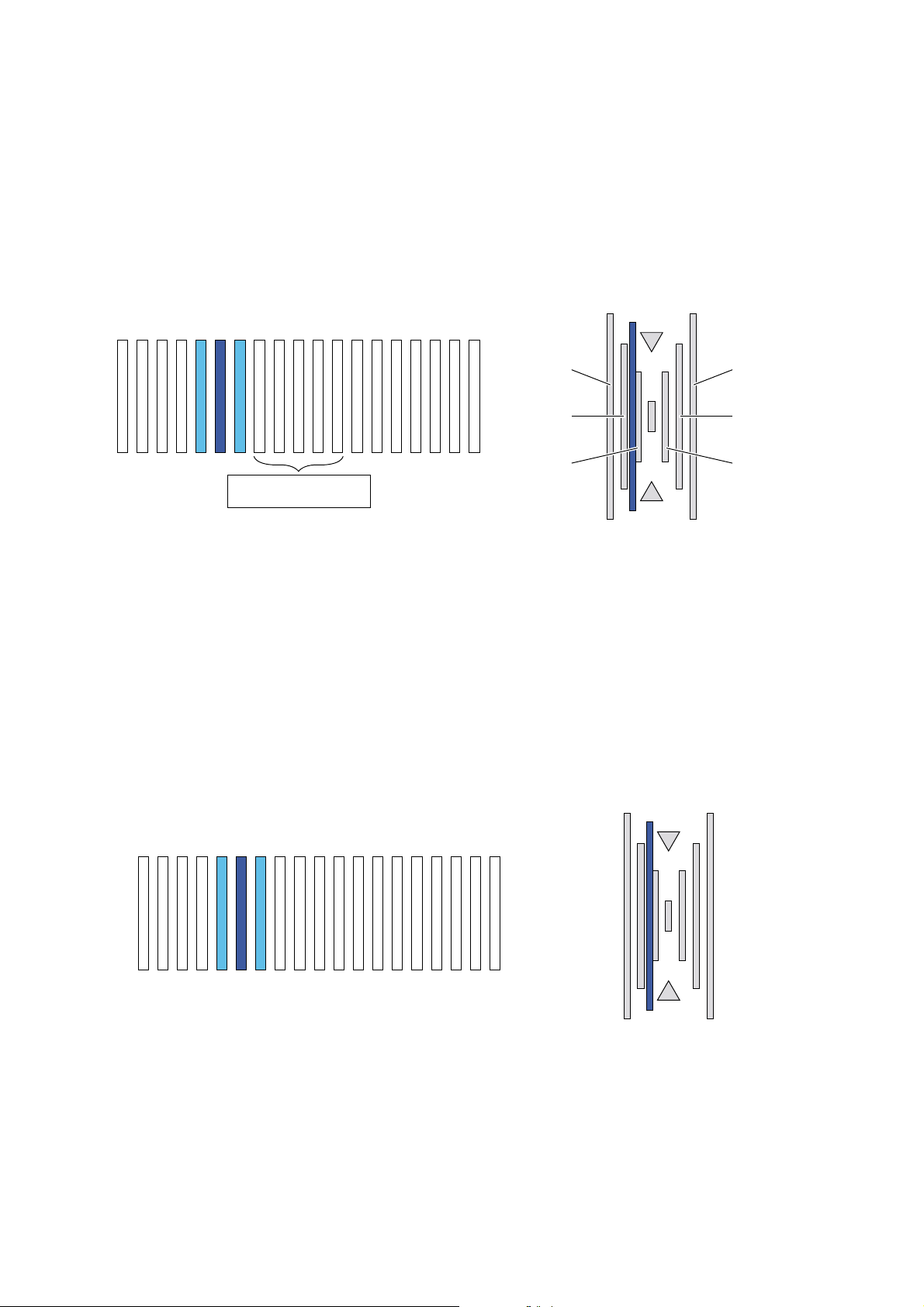
Sub scanning direction image position/print area adjustment (Print engine section)
(1) How to read the fine adjustment pattern
The highest-density area of the color is regarded as the center and as the reading value of the shift amount.
(The reading value in the figure below is 4.)
(2) How to read the rough adjustment pattern
Judge the polarity by checking that the color line is shifted to the positive or the negative side.
The scales are made with the black line at the center as 0, the first mark as 20, the second mark as 40, and the third mark as 60.
The interval between rough adjustment marks is 20.
(For an example shown in the figure below, it is between 20 and 40 on the positive side. Therefore, the reading value is 20.)
(Example)
60 -60
9 8 7 6 5 4 3 2 1 0 -1 -2 -3 -4 -5 -6 -7 -8 -9
Target adjustment range
(–2 to 2)
(3) How to calculate the adjustment value
New adjustment value = Current adjustment value + Rough adjustment
pattern reading value + Fine adjustment pattern reading value
A: Current adjustment value
B: New adjustment value
X: Fine adjustment pattern reading value
Y: Rough adjustment pattern reading value
Example
A: Providing that Current adjustment value = 48:
1) When Y ≥ 0, and X ≥ 0:
Third mark
Second mark
First mark
The polarity of the calculation differs depending on the polarity of the
adjustment pattern reading values. There are following four cases:
1) When Y ≥ 0, and X ≥ 0:
B = A + X + Y
2) When Y ≥ 0, and X < 0:
B = A + (X + 20) + Y
3) When Y < 0, and X ≥ 0:
B = A + (X – 20) + Y
4) When Y < 0, and X < 0:
B = A + X + Y
60 -60
Third mark
Second mark
First mark
9 8 7 6 5 4 3 2 1 0 -1 -2 -3 -4 -5 -6 -7 -8 -9
B = A + X + Y = 48 + (4) + (20) = 72
AR-C260/C260M SETTING AND ADJUSTMENTS 8 - 13
Page 91

2) When Y ≥ 0, and X < 0:
9 8 7 6 5 4 3 2 1 0 -1 -2 -3 -4 -5 -6 -7 -8 -9
B = A + (X + 20) + Y = 48 + (–6 + 20) + (20) = 82
3) When Y < 0, and X ≥ 0:
9 8 7 6 5 4 3 2 1 0 -1 -2 -3 -4 -5 -6 -7 -8 -9
60 -60
60 -60
B = A + (X – 20) + Y = 48 + (7 – 20) + (–20) = 15
4) When Y < 0, and X < 0:
9 8 7 6 5 4 3 2 1 0 -1 -2 -3 -4 -5 -6 -7 -8 -9
B = A + X + Y = 48 + (–5) + (–20) = 23
60 -60
AR-C260/C260M SETTING AND ADJUSTMENTS 8 - 14
Page 92

ADJ 5 Image position/print area adjustment (Print engine section)
ADJ 5A Main scanning direction image position
adjustment (Print engine section)
This adjustment must be performed in the following cases:
• When the paper tray is replaced.
• When the paper tray section is disassembled.
• When the manual paper feed tray is replaced.
• When the manual paper feed tray is disassembled.
• When the duplex section is disassembled.
• When the duplex section is installed or replaced.
• When the large capacity paper feed tray is installed or replaced.
• When the large capacity paper feed tray is disassembled.
• When a U2 trouble occurs.
• When the ICU main PWB is replaced.
• When the EEPROM of the ICU main PWB is replaced.
1) Enter the SIM 50-10 mode.
2) Select the paper feed mode to be adjusted with the scroll key.
3) Press the [EXECUTE] key.
The adjustment pattern is printed.
4) Check the adjustment pattern image position.
Measure the sizes of the void area on the front and the back edges
of the adjustment pattern, and check that the following conditions
are satisfied.
If A – B = 0 ± 4.0mm, there is no need to adjust.
If the above condition is not satisfied, perform the following procedure.
A
6) Loosen the paper feed tray cover fixing screw, and shift the installing position in the arrow direction.
Perform procedures from 2) again.
Paper feed tray cover
fixing screw
Perform the above procedures for all paper feed units.
Paper feed tray cover
fixing screw
ADJ 5B Sub scanning direction image position/
print area adjustment
(Print engine section)
This adjustment must be performed in the following cases:
• When a U2 trouble occurs.
• When the ICU PWB is replaced.
• When the EEPROM of the ICU PWB is replaced.
1) Enter the SIM 50-5 mode.
2) Select the paper feed mode with the scroll key.
3) Press the [EXECUTE] key.
The adjustment pattern is printed.
4) Check the adjustment pattern image position.
+
A–B = 0 4.0mm
-
B
5) Change the adjustment value.
(Enter the adjustment value and press the [OK] key.)
When the adjustment value is increased, the image is shifted backward.
When the adjustment value is decreased, the image is shifted forward.
A change in the set value by 1 corresponds to a change in the shift
by about 0.1mm.
Repeat procedures 3) – 5) until the condition of procedure 4) is satisfied.
If the above procedure does not satisfy the condition of 4), perform
the following procedure.
+
A = 4.0 2.0mm
+
B = 4.0 2.0mm
-
A
Measure the sizes of the void area on the left and the right edges
of the adjustment pattern, and check that the following conditions
are satisfied.
If A = 4.0 ± 2.0mm and B = 4.0 ± 2.0mm, the adjustment is not
required.
If the above condition is not satisfied, perform the following procedure.
5) Change the adjustment values of item A (DEN-C) and B (DEN-B),
and press the [EXECUTE] key.
When the adjustment value of item A (DEN-C) is decreased by 1,
the print start position in the sub scanning direction is shifted to the
paper lead edge by 0.125mm.
When the adjustment value of item B (DEN-B) is decreased by 1,
the print start position in the sub scanning direction is shifted to the
paper rear edge by 0.125mm.
Repeat procedures 3) – 5) until the condition of procedure 4) is satisfied.
B
AR-C260/C260M SETTING AND ADJUSTMENTS 8 - 15
Page 93
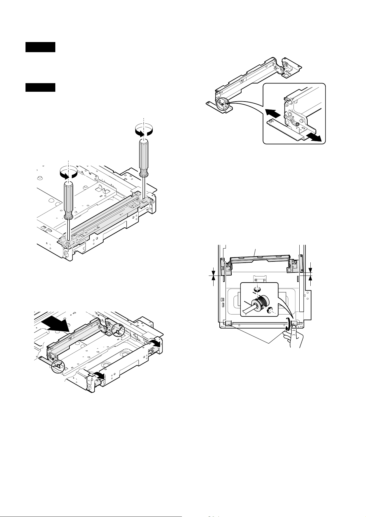
ADJ 6 Copy image distortion adjustment
This adjustment must be performed in the following cases:
• When the scanner (reading) section is disassembled.
• When a copy image distortion occurs.
ADJ 6A Scanner (reading) unit parallelism
adjustment
1) Loosen the screw that is fixing the scanner unit A and the drive
wire, and remove the scanner unit A from the drive wire.
3) Loosen the pulley angle fixing screw on the front frame side of the
scanner unit B.
4) Adjust the pulley angle position on the scanner unit B front frame
side so that both stoppers on the front frame and the rear frame
are in contact with the scanner unit B at the same time.
5) Fix the pulley angle on the scanner unit B front frame side.
If the above procedure does not result in a satisfactory result, perform the following procedure.
Loosen the fixing screw of the scanner unit drive pulley that is not
in contact.
Without moving the scanner unit drive shaft, manually turn the
scanner unit drive pulley so that the scanner unit B is brought into
contact with the stopper on the front frame side and the stopper on
the rear frame side at the same time. (Change the relative positions of the scanner unit drive pulley and the drive shaft.)
Fix the scanner unit drive pulley fixing screw.
Scanner unit B
2) Manually turn the scanner drive pulley to bring the scanner unit B
into contact with the stopper.
At that time, if the scanner unit B makes contact with the two stoppers on the front and the rear frame simultaneously, the parallelism
of the scanner unit B is proper.
If not, perform the following procedures.
Winding pulley
AR-C260/C260M SETTING AND ADJUSTMENTS 8 - 16
Page 94
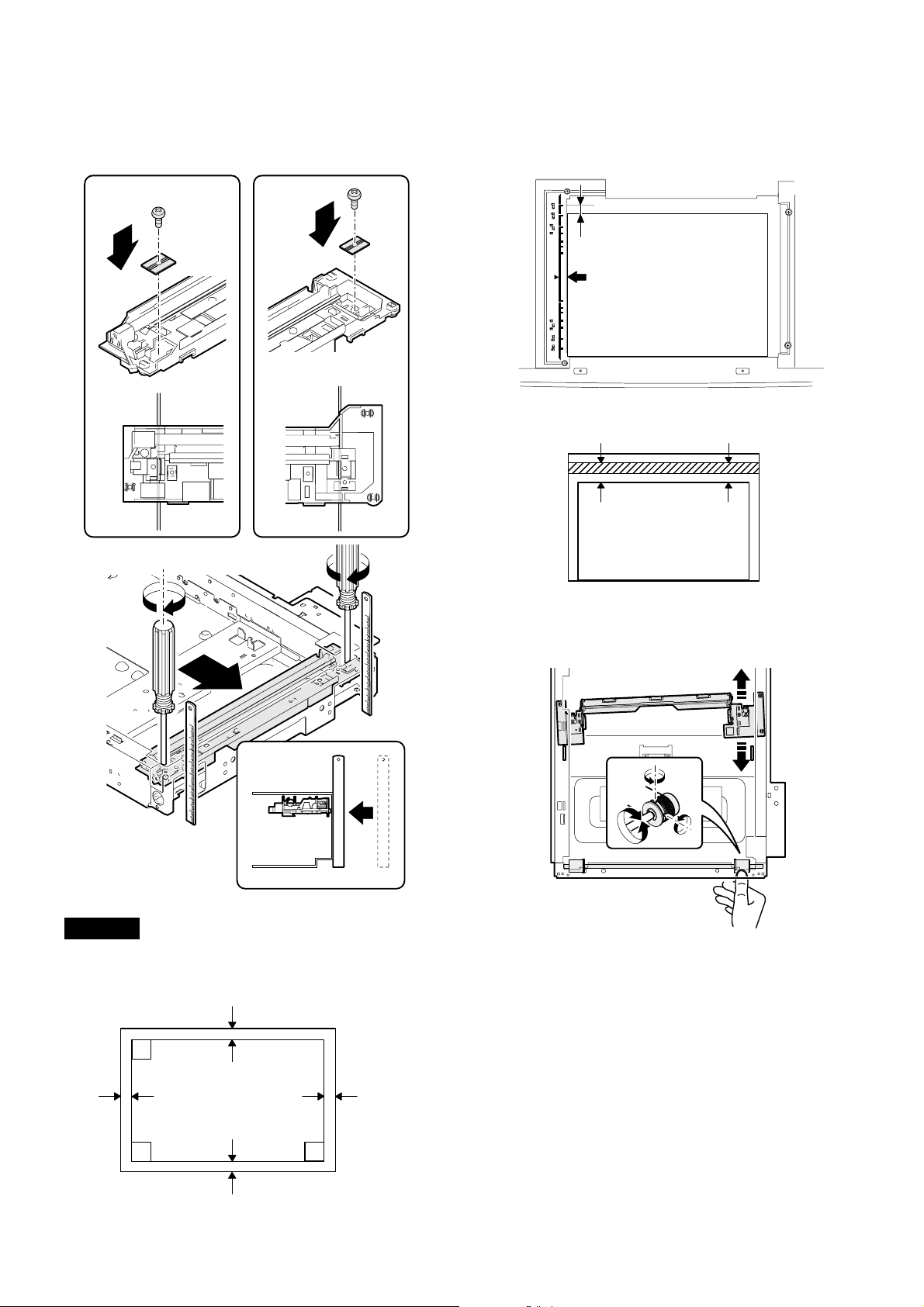
6) With the scanner unit B in contact with the both stoppers on the
CCD mounting plate at the same time, fit the edge of the scanner
unit A with the frame right edge and fix the scanner unit A with the
screw.
2) Set the test chart made in procedure 1) on the document table.
(Leave a space of about 30mm between the reference position and
the test chart.) With the document cover open, make a copy on A3
(11" x 17").
3) Check for distortion in the sub scanning direction.
If La = Lb, there is no distortion.
LbLa
ADJ 6B Copy image sub scanning direction
distortion adjustment
1) Make a test chart on A3 (11" x 17") paper as shown below. (Draw a
rectangular with four right angles.)
L
L
L
If there is some distortion in the sub scanning direction, perform the following procedures.
4) Loosen either of two fixing screws of the scanner unit drive pulley.
(Either one on the front or the rear side will do.)
5) With the scanner unit drive shaft kept stationary, turn the scanner
unit drive pulley manually to change the parallelism of scanner
units A and B. (Change the relative positions of the scanner unit
drive pulley and the drive shaft.)
6) Tighten the scanner unit drive pulley fixing screw.
Repeat procedures 2) – 6) until the condition of procedure 3) is satisfied.
If the distortion in the sub scanning direction cannot be deleted with the
above procedures, perform ADJ 6D, Scan image distortion adjustment.
L = 10mm
L
AR-C260/C260M SETTING AND ADJUSTMENTS 8 - 17
Page 95
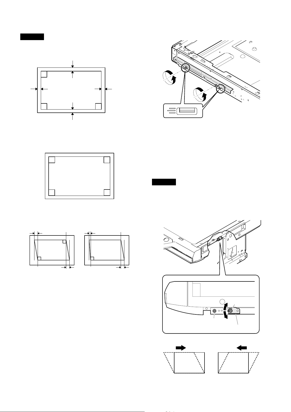
ADJ 6C Copy image main scanning direction
distortion adjustment
1) Make a test chart on A3 (11" x 17") paper as shown below. (Draw a
rectangle with four right angles.)
L
4) Loosen the screw on the right side of the MB rail.
L
L
2) Set the test chart made in procedure 1) on the document table.
With the document cover open, make a copy on A3 (11" x 17").
3) Check for distortion in the main scanning direction.
If the four angles of the rectangle on the copy are right angles,
there is no distortion. (Completion of the adjustment)
If there is some distortion in the main scanning direction, perform the
following procedures
4) Check the difference (distortion balance) of left and right images
distortions.
Lc
Lc
L
L = 10mm
Repeat procedures 2) to 5) until the image distortions are balanced.
6) Without changing the balance between the front frame side scanner rail, change the overall height.
7) Set the test chart made in procedure 1) on the document table, and
make a copy on A3 (11" x 17") paper. Check that the main scanning distortion is within the specified range.
Perform procedures 7) to 8) until the main scanning direction distortion is in the specified range.
If this adjustment cannot remove the sub scanning direction distortion,
perform ADJ 6D, Scan image distortion adjustment.
ADJ 6D Scan image distortion adjustment
If scan image distortion cannot be removed with ADJ 6A, ADJ 6B, and
ADJ 6C, perform this adjustment.
Change the position of the scanner unit distortion adjustment plate on
the right side of the scanner unit so that the scanner image distortion
becomes minimum. The scan image distortion is adjusted by adjusting
the overall mechanical distortion of the scanner unit.
Copy A
Ld
There is no difference
between the distortion on
the right and that on the left.
Lc = Ld
If Lc = Ld, the distortion on the left is equal to that on the right. (The
distortions are balanced.)
If the above condition is satisfied, go to procedure 6).
If the above condition is not satisfied, perform the following procedure.
5) Change the height balance of the front frame side scanner rail.
[Rail adjustment]
1) Make a copy from the table glass, and check the copy output.
In this case, set the test chart correctly. If it is set inclined, the
adjustment cannot be made correctly.
2) If the check result is outside the specified range, perform the
following procedure.
3) Remove the front cabinet on the scanner side, and check the
installing position of the MB rail.
There is some difference
between the distortion on
the right and that on the left.
Copy B
Ld
Lc ≠ Ld
AR-C260/C260M SETTING AND ADJUSTMENTS 8 - 18
B
A
A
Scanner adjustment plate WH
BC
C
Page 96

ADJ 7 Copy image focus (main
10 20 90 100 110
10 20 90 100 110
scanning direction copy
magnification ratio) adjustment
(CCD unit position adjustment)
This adjustment must be performed in the following cases:
• When the CCD unit is removed from the machine.
• When the CCD unit is replaced.
• When the copy image focus is improper.
• When the copy magnification ratio in the copy image main scanning
direction is not proper.
• When the MFP main PWB is replaced.
• When the EEPROM of the MFP main PWB is replaced.
• When a U2 trouble occurs.
1) Enter the SIM 48-1 mode.
2) Set the set item B to 50 (initial value).
3) As shown in the figure below, place a scale on the original table.
10 20 3040 50 60 70 80 90 50 100110120130140
4) Make a normal copy on A4 paper.
5) Compare the scale image length and the actual scale length.
6) Obtain the main scanning direction copy magnification ratio
according to the following formula.
Main scanning direction copy magnification ratio
(Original dimension – Copy dimension)
= x 100 [%]
(Example) Fit 10mm of the scale with 10mm of the copied scale and
100mm scale
(Original)
Copy image
(1mm (1%)
shorter than
the original)
If the copy magnification ratio is not satisfactory, perform the following procedure.
7) Remove the original guide L and R, and remove the table glass.
8) Remove the dark box cover.
9) Loosen the CCD unit fixing screws.
Draw a marking line on the CCD unit base as shown below in order
to avoid a shift in the optical axis of the CCD unit.
At that time, fix the CCD unit so that it is in parallel with the marked
line in procedure 9).
Original dimension
compare them.
Main scanning direction copy magnification ration
– 99
100
= x 100 = 1
100
1.0mm
∗ Never loosen the screws marked with "✕."
If one of these screws is loosened, the CCD unit base position
and angle may be changed. If so, it cannot be adjusted in the
market, and therefore the whole scanner unit must be replaced.
10) Slide the CCD unit in the arrow direction (CCD sub scanning direction) to change the installing position.
When the copy image is longer than the original, move in the direction of B.
When the copy image is shorter than the original, move in the
direction of A.
One scale of scribe line corresponds to 0.2%.
At that time, fix so that the CCD unit is in parallel with the scales on
the front frame side and on the rear frame side of the CCD unit
base.
B
A
At that time, fix the CCD unit so that it is in parallel with the marked
line in procedure 9).
AR-C260/C260M SETTING AND ADJUSTMENTS 8 - 19
Page 97

11) Make a copy, and check the copy magnification ratio.
If the copy magnification ratio is outside the range of 100% ± 1%,
repeat procedures 9) to 11) until it is in the range.
Note: Due to the structure of the optical system, when the CCD unit
fixing position is changed with SIM 48-1 set to 50, the copy magnification ratio is adjusted to the specified level (100 ± 1.0%) and
the specified resolution is provided.
ADJ 8 Sub scanning direction copy
magnification ratio adjustment
This adjustment must be performed in the following cases:
• When the copy magnification ratio in the copy image sub scanning
direction is improper.
• When the scanner motor is replaced.
• When a U2 trouble occurs.
• When the MFP main PWB is replaced.
• When the EEPROM of the MFP main PWB is replaced.
Before this adjustment, perform the focus adjustment (CCD unit installing position adjustment).
1) Place a scale on the original table as shown below.
102030 40
50 60 70
80 90 50
100
110
120130140
4) Check that the copy magnification ratio is within the specified
range (100 ± 1.0%).
If the copy magnification ratio is within the specified range (100 ±
1.0%), the adjustment is completed.
If not, perform the following procedure.
5) Change the scan mode adjustment value of SIM 48-1.
When the adjustment value is increased, the sub scanning direction copy magnification ratio is increased.
A change in the adjustment value by 1 corresponds to a change in
the copy magnification ratio by about 0.1%.
Repeat procedures 3) to 5) until the coy magnification ratio is
within the specified range (100 ± 0.28%).
Note: Fix the adjustment value of SIM 48-1 adjustment mode (F – R)
to 50.
ADJ 9 Main scanning direction copy
image position adjustment
(Scanner (reading) section)
This adjustment must be performed in the following cases:
When the scanner (reading) section is disassembled.
When the scanner (reading) unit is replaced.
When the RADF section is disassembled.
When the RADF unit is installed.
When the RADF unit is replaced.
When a U2 trouble occurs.
When the MFP main PWB is replaced.
When the EEPROM of the MFP main PWB is replaced.
1) Make a copy in the adjustment chart adjustment mode. (Document
table or RADF)
2) Check the copy image center position.
If A – B = ± 4.0mm, there is no need to adjust.
2) Enter the SIM 48-1 mode.
3) Make a normal copy and obtain the copy magnification ratios.
Copy magnification ratio
(Original dimension – Copy dimension)
= x 100 [%]
(Example 1)
Copy A
(Shorter than
the original)
Scale
(Original)
(Example 2)
Copy B
(Longer than
the original)
Original dimension
10
10
10
20
90 100 110
20 90 100
20 90 100
110
110
A
A– B = 4.0mm
(400%)
B
If the above condition is not satisfied, perform the following procedures.
3) Enter the SIM 50-12 mode.
4) Select the adjustment mode with the scroll key.
5) Enter the adjustment value with the 10-key and press the [OK] key.
The entered value is set.
∗ When the set value is increased, the image is shifted to the rear
side. When the set value is decreased, the image is shifted to the
front side.
When the set value is change by 1, the image is shifted by about
0.4mm.
Repeat procedures 2) to 5) until the above condition is satisfied.
AR-C260/C260M SETTING AND ADJUSTMENTS 8 - 20
Page 98

ADJ 10 Copy image position/image loss/
void area adjustment
This adjustment must be performed in the following cases:
• When the scanner (reading) section is disassembled.
• When the scanner (reading) unit is replaced.
• When the resist roller section is disassembled.
• When a U2 trouble occurs.
• When the MFP main PWB is replaced.
• When the EEPROM of the MFP main PWB is replaced.
This adjustment uses SIM 50-2 and SIM 50-1.
The above two simulations are used in the following manner.
SIM 50-2: Rough adjustment
SIM 50-1: Fine adjustment
If the desired value is obtained by SIM 50-2, there is no need to perform SIM 50-1.
(Adjustment item)
No. Adjustment item
1 Lead edge image loss IMAGE
2 Lead edge void area DEN-A DEN-A 4.0 ±
3 Rear edge void area DEN-B DEN-B 4.0 ±
4 Image reference position RRC-A
5 Paper timing RRC-B
6 Distance between image lead
edge position and scale of
10mm x 10
7 Distance between paper lead
edge and image lead edge x 10
SIM 50-2
set item
LOSS
L1
L2
Adjustment items 1 to 3 can be adjusted either with SIM 50-1 or with
SIM 50-2.
The adjustment values 6 and 7 will affect the adjustment items 4 and 5
automatically.
Therefore, adjusting the items 6 and 7 will lead to the same result as
adjusting the items 4 and 5 directly.
1) Place a scale on the original table as shown below.
Note that the scale must be placed in parallel with the scanning
direction and that the scale lead edge must be in close contact with
the original guide plate.
10 20 30 40 50 60 70 80 90 50 100110120130140
SIM 50-1
set item
IMAGE
LOSS
Adjustment
value
4.0 ±
1.0mm
1.0mm
1.0mm
6) Measure the copied image dimensions X and Y.
X: Distance between the copy image lead edge and the scale of
10mm.
Y: Distance between the paper lead edge and the copy image
lead edge.
X
Paper lead
edge
10 20 30 40
50
400% enlarged copy
Y
7) Multiply X, Y, and Z (unit: mm) by 10 to obtain L1, L2 respectively.
Enter the values of L1, L2, and L3.
L1 = X x 10
L2 = Y x 10
8) Cancel the simulation, make a copy, and check that the lead edge
image loss and void area are within the specified range shown
below.
Lead edge image loss: 4.0 ± 1.0mm
Lead edge void area: 4.0 ± 1.0mm
If the above specifications are not satisfied, perform the following procedures.
9) Enter the SIM 50-1 mode.
10) Set a scale in the same manner as procedure 3), and make a copy
at 50% and at 400% in the original table mode.
11) Measure the distance between the paper lead edge and the copy
image lead edge of 50% copy and of 400% copy.
12) Check that there is no difference between the above distance of
50% copy and that of 400% copy.
If there is a difference of 1.5mm or above, change the adjustment
value of RRC-A.
Repeat procedures 10) to 12) until the above specification is satisfied.
13) If the lead edge void area is not within the specified range, change
the DEN-A value.
14) If the lead edge void area is not within the specified range, change
the IMAGE LOSS value.
15) If the rear edge void area is not within the specified range, change
the DEN-B value.
2) Enter the SIM 50-2 mode.
3) Set IMAGE LOSS and DEN-A to "20".
4) Set all the set items of L1 and L2 to "0".
5) Make a copy at 400%. (Original table mode)
AR-C260/C260M SETTING AND ADJUSTMENTS 8 - 21
Image loss
Lead edge void area Rear edge void area
Page 99

Adjustment item
IMAGE
LOSS
DEN-A Lead edge void
DEN-B Rear edge void
Lead edge image
loss
area
area
Adjustment
value
4.0 ±
1.0mm
4.0 ±
1.0mm
4.0 ±
1.0mm
Note
The greater the set value is,
the greater the image loss is.
The greater the set value is,
the greater the void area is.
The greater the set value is,
the greater the void area is.
ADJ 11 Copy color balance/density adjustment
(1) Note for the copy color balance/density adjustment
(Necessary conditions for execution of the copy color balance/density adjustment)
Before execution of the copy color balance/density adjustment, check that all the adjustments related to the copy color balance and density have been
completed properly.
The importance level is as shown below.
(Adjustment items which directly affect the copy color balance and density and must be checked or adjusted before
execution of the image quality adjustment)
1) Adjustment items: ADJ 2, ADJ 3, ADJ 4
JOB No ADJUSTMENT ITEM LIST SIMULATION
ADJ 2 Image density sensor adjustment 44-36
ADJ 3 Image focus, image skew adjustment (LED (writing) unit) 64-1/61-4
ADJ 4 Image registration adjustment ADJ 4A Image registration adjustment (Auto adjustment) 50-22
ADJ 4B Image registration adjustment (Manual adjustment) 50-20
The user color balance adjustment must be set to the center (default).
Item Purpose Note
User color balance setting: Default (Center) (Special function) Set the color balance to the standard state. Check that it is set to the center.
The set value of SIM 46-27 is set to the default.
SIM
No
Display/Item
46-27 A BLACK TEXT
(SLOPE)
Setting
(Default)
Content
Black image edge section
gamma (tilt) adjustment
(Black text and black line
reproduction adjustment)
50
BBLACK TEXT
(INTERCEPT)
Black image edge section
density (overall level)
50
adjustment (Black txt and
black line reproduction
adjustment)
The set value of the following simulation must be set to the default.
SIMNo Item
46-1
46-2
46-10 to 16
46-20
Setting
(Default)
A– R 50
A– O 50
A – O 500
A – O 500
Phenomenon when the set value is
changed
The density and color balance in the low
density section of color copy are changed.
The density in the low density section of
monochrome copy is changed.
The color copy density and color balance
are changed. (each copy mode)
The color copy density and color balance
of all copy modes are changed.
Phenomenon when the set
value is changed
When the set value is
increased, the contrast of
black line and black text
outline sections is reduced. On
the contrary, when the set
value is decreased, the
contrast is increased.
(Sharpness of black text and
black lines is changed.) (Text/
Printed photo, Text, Text/
Photograph copy mode)
The density of black lines and
black text outline is changed.
(Text/Printed photo, Text,
Text/Photograph copy mode)
Set to the default when adjusting the copy quality.
Do not adjust the density in the low density section by using this
simulation.
Set to the default when adjusting the copy quality.
Set to the default when adjusting the copy quality.
Phenomenon occurring
when the adjustment
value is not within the
normal value range.
The contrast and density
of lines and text outline
section are changed.
(Sharpness of text and
lines is changed.) (Text/
Printed photo, Text, Text/
Photograph copy mode)
Note
Note
For image
quality
adjustment, set
to 50.
AR-C260/C260M SETTING AND ADJUSTMENTS 8 - 22
Page 100

The following functions (HV/HT/TC/RRM/MD) of SIM 44-1 must be set to Enable.
Item Setting Phenomenon when set to Disable
HV Image forming section
correction (process
correction) (High-density
image density correction)
HT Half-tone image density
correction
TC Transfer output correction ENABLE Correction of change due to humidity and
RRM RRM speed correction ENABLE Correction of change due to humidity and
MD Photoconductor
membrane decrease
(sensitivity/potential)
correction
AR Image registration
automatic adjustment
AR CHK YES/NO of error
judgment in image
registration automatic
adjustment
ENABLE The developing bias voltage correction and the
main charger grid voltage correction are not
performed.
ENABLE The half-tone image density correction is not
performed.
correction of the transfer voltage are not
performed.
correction of the rotate speed are not
performed.
ENABLE Correction of use frequency (sensitivity
change) of OPC drum is not performed. (Main
charger grid voltage correction)
Does not affect during image quality
adjustment.
Does not affect during image quality
adjustment.
Insufficient image density, background coy,
improper color balance
Improper half-tone image density, background
copy, improper color balance, tone jump
Half-ton image section roughness, improper
image density, insufficient density inside of
image outlines
Improper color balance, roughness,
background coy, toner dispersion, improper
image density, image deflection, image flow,
image dirt
Improper image density, background copy
(Adjustment items which affect the copy color balance/density but need not to be adjusted frequently. When, however, a
trouble occurs, check and adjustment must be made.)
1) Adjustment item: ADJ 1, ADJ 7, ADJ 12, ADJ 13
JOB No ADJUSTMENT ITEM LIST SIMULATION
ADJ 1 High voltage adjustment ADJ 1A Main charger grid voltage adjustment 8-2
ADJ 1B DV bias voltage adjustment 8-1
ADJ 1C Transfer voltage adjustment 8-6
ADJ 7 Copy image focus (main scanning direction copy magnification ratio) adjustment (CCD unit position adjustment) 48-1
ADJ 12 Fusing pressure adjustment
ADJ 13 Fusing paper guide position adjustment
(Relationship between the service contents and the copy color balance/density adjustment)
Note that procedures before and after the copy color balance/density adjustment differ depending on the machine status and the servicing job contents.
Perform proper procedures according to the flow of the copy color balance/density adjustment.
There are following five major cases:
1) When installing
2) When periodic maintenance
3) When consumable part is replaced in repair work
4) When consumable part is not replaced in repair/checking work
5) Other repair/check
AR-C260/C260M SETTING AND ADJUSTMENTS 8 - 23
 Loading...