

Page 1

S E R VIC E MANUAL
C ODE : S M-A R C 240P -1
DIG IT A L C OL OR L E D P R INT E R
MODE L
C ONT E N T S
[1] C ONF IG UR AT IONS . . . . . . . . . . . . . . . . . . . . . . . . . . . . . . . . . . . 6
[2] P AR T S R E PL AC E ME NT . . . . . . . . . . . . .. . . . . . . . . . . . . . . . . . . 17
[3] ADJ US TME NT S . . . . . . . . . . . . . . . . . . . . . . . . . . . . . . . . . . . . . . 76
[4] R E G UL AR MAINT E NANC E . . . . . . . . . . . . . . . . . . . . . . . . . . . . . . 110
[5] T R OUB LE S HO OT ING P R OC E DUR E S . . . . . .. . . . . . . . . . . . . . . . 111
[6] C ONNE C T IO N DIAG R AM . . . . . . . . . . . . . . . . . . . . . . . . . . . . . 146
[7] AP P E NDIX A INT E R F AC E S P E C IF IC AT IONS . .. . . . . . . . . . . . . 156
[8] AP PE NDIX B 2ND/3R D T R AY MAINT E NANC E . . . . . . . . . . . . . . . 160
AR -C 240P
[9] AP PE NDIX C E R R O R ME S S AG E S . . . . . . . . . . . . . . . . . . . . . . . . 165
[10] P AR T S G UIDE . . . . . . . . . . . . . . . . . . . . . . . . . . . . . . . . . . . . . . . . 180
P arts marke d with “ ” a re important for ma intaining the s afety of the s et. B e s ure to re place thes e pa rts with
specified ones for maintaining the s afety a nd performa nc e of the s et.
This docume nt has been publishe d to be us ed
S HA R P C OR P O R A T ION
for a fter s ales s ervice only.
The contents are s ubject to cha nge without notice.
Page 2

Page 3

CONTENTS
1. CONFIGURATIONS ......................................................................................... 6
1.1 System Configuration....................................................................................................... 6
1.2 Printer Configuration ........................................................................................................7
1.3 Supplies and Consumables.............................................................................................. 8
1.4 Specifications ................................................................................................................... 9
2. PARTS REPLACEMENT................................................................................ 17
2.1 Precautions in Replacing Parts ...................................................................................... 17
2.2 Parts layout .................................................................................................................... 19
2.3 Replacing Parts..............................................................................................................25
2.3.1 Top Cover......................................................................................................... 27
2.3.2 LED Head / LED Spring / Post-Guide............................................................... 28
2.3.3 Top Cover Unit ................................................................................................. 29
2.3.4 Control Panel Assy/ Control Panel Bezel/ LED Control PWB/ Toner Sensors/
Stacker Full Sensor/ Control Panel/ Control Panel Tape Harness/
Eject Rollers ..................................................................................................... 30
2.3.5 Top Cover Handle/ Top Cover Latch/ Top Cover Latch Spring........................ 31
2.3.6 Eject Guide Assy .............................................................................................. 32
2.3.7 Cassette Assy/ Front Cover Assy/ Front Cover Inner Baffle ........................... 33
2.3.8 Retard Pad Assy/ Retard Pad Assy Spring ...................................................... 34
2.3.9 Feed Roller and Nudger Roller......................................................................... 35
2.3.10 Rear Cover ....................................................................................................... 36
2.3.11 Face-Up Tray.................................................................................................... 37
2.3.12 Left Side Cover................................................................................................. 38
2.3.13 Right Side Cover .............................................................................................. 39
2.3.14 Multipurpose Tray Assy/ Multipurpose Tray Cover Assy/ Links/
Multipurpose Tray Top Cover/ Multipurpose Tray Drive Gear.......................... 40
2.3.15 Drum Contact Assys......................................................................................... 41
2.3.16 Media Thickness Sensor Assy......................................................................... 42
2.3.17 Registration Roller Assy (A)/ Registration Drive Gear (A) ................................ 43
2.3.18 Registration Roller Assy (B) ............................................................................. 44
2.3.19 Registration Clutch and Registration Motor Assy ............................................. 45
2.3.20 Main Cooling Fan ............................................................................................. 46
2.3.21 Color Registration Sensor Assy........................................................................ 47
2.3.22 Duplex Guide Assy ........................................................................................... 48
2.3.23 Electrical Chassis Cooling Fan......................................................................... 49
2.3.24 Printer Engine Controller PWB ......................................................................... 50
2.3.25 Printer Unit Chassis.......................................................................................... 51
2.3.26 Entrance Cassette Sensor Actuator ................................................................. 52
2.3.27 Entrance Sensor PWB...................................................................................... 53
2.3.28 Entrance MT Sensor Actuator / Entrance Belt Sensor Actuator /
Entrance Waste Chassis Sensor Actuator ...................................................... 54
2.3.29 Fuser Exit Roller ............................................................................................... 55
2.3.30 Exit Sensor Assy .............................................................................................. 56
2.3.31 Fuser Latching Handle (L) ................................................................................ 57
2.3.32 Belt Motor Assy ................................................................................................ 58
2.3.33 Fuser Latching Handle (R) ............................................................................... 59
2.3.34 Main Motor Assy............................................................................................... 60
2.3.35 Main Feeder Drive Motor.................................................................................. 61
2.3.36 Contact Assy/ Left Plate Assy .......................................................................... 62
2.3.37 Low Voltage Power Supply............................................................................... 63
2.3.38 High voltage power supply ............................................................................... 64
2.3.39 Main Feed Assy................................................................................................ 65
2.3.40 Cassette/ Left Guide Assy ................................................................................ 66
2.3.41 Cassette/ Right Guide Assy.............................................................................. 67
2.3.42 Fuser Unit ......................................................................................................... 68
3 /
Page 4

2.3.43 Belt Unit ............................................................................................................ 69
2.3.44 Duplex Unit ....................................................................................................... 70
2.3.45 Guide Rails (L) and (R)..................................................................................... 71
2.3.46 Duplex Transport Assembly ............................................................................. 72
2.3.47 CU Assy............................................................................................................ 74
3. Adjustment .................................................................................................... 76
3.0 System Maintenance MENU .......................................................................................... 76
3.0.1 ID Check Pattern Printing ( " TEST PRINT MENU " item )............................... 77
3.1 Maintenance Mode and Functions ................................................................................. 77
3.1.1 Maintenance menu ........................................................................................... 77
3.1.2 Engine maintenance mode............................................................................... 79
3.1.2.1 Operator panel .................................................................................. 79
3.1.2.2 Normal self-diagnostic mode (Level 1).............................................. 79
3.1.2.2.1 Entering self-diagnostic mode (Level 1) ............................ 80
3.1.2.2.2 Exiting the self-diagnostic mode ....................................... 80
3.1.2.3 Switch scan test ................................................................................ 80
3.1.2.4 Motor clutch test ................................................................................ 84
3.1.2.5 Test print ........................................................................................... 86
3.1.2.6 Initializing NVM ................................................................................. 90
3.1.2.7 Displaying the consumables counter ................................................ 91
3.1.2.8 Displaying the consumables continuation counter ............................ 91
3.1.2.9 Panel display details ......................................................................... 92
3.1.3 Various print jobs with single printer unit attached with a controller ................. 97
3.2 Adjustment After Replacing Parts .................................................................................. 98
3.2.1 Precautions in replacing the engine control board ........................................... 98
3.2.2 Precautions in replacing EEPROM................................................................... 98
3.2.3 Replacing EEPROM after replacing the TIG board .......................................... 99
3.2.4 Destination Setting (Checking Metod: Printing Demo Page)............................ 99
3.2.5 Recovery Flash ROM data on TIG board ....................................................... 100
3.3 Adjusting the Density ....................................................................................................100
3.4 Paper Thickness Detection Sensitivity Adjustment and Media Thickness Detection
Value Check..................................................................................................................101
3.4.1 Applicable Operating Systems and Interfaces, and File Required ................. 101
3.4.2 Setting ............................................................................................................ 102
3.4.2.1 Menu Setting ....................................................................................102
3.4.2.2 Media Setting ...................................................................................104
3.4.2.3 Sensitivity Adjustment ..................................................................... 105
3.4.2.4 Actions for NG Sensitivity Adjustment............................................. 106
3.4.3 Inputting the density of the calibration chip for density detection ................... 107
3.4.3.1 Density Adjustment Menu Setting ................................................... 107
3.4.4 Electronic Serial Number Input....................................................................... 109
4. regular maintenance ................................................................................... 110
4.1 Parts Replaced Regularly ............................................................................................ 110
4.2 Cleaning ....................................................................................................................... 110
4.3 Cleaning the LED Lens Array ...................................................................................... 110
4.4 Cleaning the Pick-up Roller ......................................................................................... 110
5. Troubleshooting Procedures ..................................................................... 111
5.1 Precautions before troubleshooting ............................................................................. 111
5.2 Precautions before handling an abnormal image ........................................................ 111
5.3 Precautions upon handling an abnormal image........................................................... 111
5.4 Preparing for Troubleshooting ..................................................................................... 112
5.5 Troubleshooting Procedure.......................................................................................... 112
5.5.1 LCD message list ........................................................................................... 113
5.5.2 Preparing for troubleshooting ......................................................................... 119
5.5.3 Troubleshooting for abnormal images ............................................................ 130
5.6 Fuse check................................................................................................................... 145
4/
Page 5

PARTS GUIDE.................................................................................................................180
6. CONNECTION DIAGRAM ............................................................................ 146
6.1 Resistance Checks ...................................................................................................... 146
6.2 Program/Font ROM Layouts ........................................................................................ 150
APPENDIX A INTERFACE SPECIFICATIONS ................................................. 156
1. Parallel Interface Specifications ................................................................................... 156
1.1 Parallel Interface..............................................................................................156
1.2 Parallel Interface Connector and Cable.......................................................... 156
1.3 Parallel Interface Level ................................................................................... 156
1.4 Timing Charts ................................................................................................. 157
1.5 Parallel I/F Signals.......................................................................................... 158
2. Universal Serial Bus (USB) Interface Specifications.................................................... 159
2.1 USB Interface ................................................................................................. 159
2.2 USB Interface Connector and Cable .............................................................. 159
2.3 USB Interface Signals .................................................................................... 159
APPENDIX B 2ND/3RD TRAY MAINTENANCE .............................................. 160
1. Parts Replacement ...................................................................................................... 160
1.1 Cover Idle Roller Assy .................................................................................... 160
1.2 PCB ................................................................................................................ 161
1.3 Feeder Drive Assy .......................................................................................... 162
2. 2nd/3rd Tray PARTS LIST ............................................................................ 163
APPENDIX C ERROR MESSAGES ................................................................. 165
1. Error messages ........................................................................................................... 165
2. Error messages : Color, Media Detect ......................................................................... 172
3. Warning messages : usage, media .............................................................................. 175
4. Warning messages : Job Account ................................................................................ 176
5. Other Warning .............................................................................................................. 177
5/
Page 6

1. CONFIGURATIONS
1.1 System Configuration
Figure 1-1 shows the system configuration of the ARC200P.
M
Hopping
M
MT/
Registration
M
M
<Sensors, Switches and Thermistors>
Pulse Motor
M
Paper size sensor (4 bits)
Paper empty sensor
Paper near empty sensor
MT paper empty sensor
FF home switch
Loading sensor 1
Loading sensor 2
Media Thickness Detection
Density Detection
< advanced Sensors,>
Color Misalignment Detectin
LED Head
C ID M ID Y ID K IDBelt Heat
M M
M
Junction Board
Engine Control
Power Unit
Low Voltage
2nd/3rd Tray
Power Unit
High Voltage
Fuser
Unit
Unit
Duplex
Unit
K-ID
Unit
C-ID
Unit
M-ID
Unit
Y-ID
Belt
Unit
Figure 1-1
Operator Panel
IDE
DIMMs
3 ⋅ ROM
Centronics I/F
6 /
DIMM
4 ⋅ RAM
USB I/F
I/F(HDD)
Note
2 ⋅ Option Slots
DC Fan
LAN Card made by JCI
Note Option Slot:
Page 7
1.2 Printer Configuration
The inside of the printers is composed of the followings:
• Electrophotographic Processor
• Paper Paths
• Controller Block (CU and PU)
• Operator Panel
• Power Units (High Voltage Unit and Low Voltage Unit)
Figure 1-2 shows the printer configuration.
B
A
A
B
B
A
A
Figure 1-2
7 /
Page 8

1.3 Supplies and Consumables
8 /
Product Code Description Quantity Estimated Yield Comments
AR-C20TBU Black Toner Cartridge
AR-C20TCU Cyan Toner Cartridge
AR-C20TMU Magenta Toner Cartridge 1
AR-C20TYU Yellow Toner Cartridge 1
AR-C20BDR Black Image Drum
AR-C20CDR Cyan Image Drum
AR-C20MDR Magenta Image Drum
AR-C20YDR Yellow Image Drum
AR-C20TB1 Transfer Belt 1 60,000 Images/Belt
AR-C20FU1 Fuser Unit 1 60,000 Images/Belt
Deluxe Printer Cabinet
AR-C20ABD
(with Door)
1
1
1 30,000 Images/Unit
1 30,000 Image/Unit
1 30,000 Images/Unit
1 30,000 Images/Unit
10,000
Images/Cartridge
10,000
Images/Cartridge
10,000
Images/Cartridge
10,000
Images/Cartridge
@ 5% Image
Area
@ 5% Image
Area
@ 5% Image
Area
@ 5% Image
Area
(Customer
replaceable)
(Customer
replaceable)
(Customer
replaceable)
(Customer
replaceable)
(Customer
replaceable)
(Customer
replaceable)
Page 9
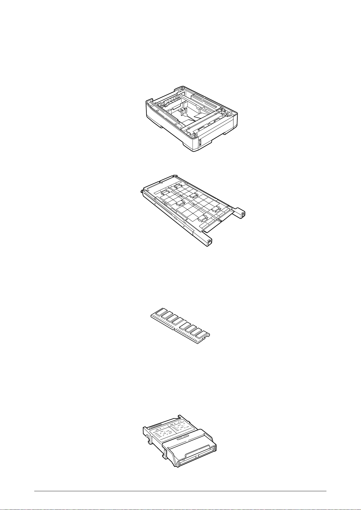
Option Configuration
(4) Internal Hark Disk (AR-C20HD)
SHP16x64S133C3 (128MB)
SHP32x64S133C3-B (256MB)
SHP64x64S133C3 (512MB)
The followings are available as options on the ARC200P.
(1) 2nd Tray/ 3rd Tray (AR-C20PFU)
(2) Duplex Unit (AR-C20ADU)
(3) Expansion Memory
9 /
Page 10

1.4 Specifications
(1) External Dimensions Height: 430mm Width: 430mm Length: 620mm
(2) Weight 42 kg
(3) Papers Type: Ordinary paper, Transparencies (Recommended: MLOHP01)
(4) Print Speed Color: 20 pages per minute (Transparency: 8 pages per minute)
(5) Resolution 600 ⋅ 600 dots per inch
Size: Postal card, Legal 13" or 14", Executive, A4, A5, B5, A6 (Only
the 1st tray and the front feeder support A6 and postal-card
sizes.)
2
Weight: 1st tray55 kg to 151 kg (64 to 176g/m
Front feeder 55 kg to 172 kg (64 to 203g/ m
)
2
)
Monochrome: 24 pages per minute (Transparency: 12 pages per minute)
Postal Card, Label, Thick Paper: 12 pages per minute
(6) Power Input 115 - 127 V , 220 - 240 V
(7) Power Consumption Peak: 1500W Normal Operation: 500W (5% duty)
Idle: 150W Power Saving Mode: 45W or less
(8) Frequency 50Hz or 60Hz ±2Hz
(9) Noise Operation: 56 dB (Without second tray)
Standby: 45 dB
Power Saving: 43 dB
(10) Consumable Life Toner Cartridge: 5,000 pages (5% duty) (each of Y, M, C and K)
Large-Capacity Toner Cartridge: 10,000 pages (5% duty)
(each of Y, M, C and K)
Image Drum: 30,000 pages (5% duty, Continuous printing)
(each of Y, M, C and K)
(11) Parts Replaced Periodically Fuser Unit Assy: Every 60,000 pages
Belt Cassette Assy: Equivalent of 60,000 pages (3 pages/job)
10 /
Page 11

(12) Temperatures and Relative Humidities
Temperature
Temperature Condition
Temperature( F) Temperature( C) Remark
Operation 50 to 89.6 10 to 32 17 to 27 C
(Temperatures to assure full
color print quality)
Non-Operation 32 to 109.4 0 to 43 Power-off
Storage (Max. One Year) -14 to 109.4 -10 to 43 With drum and toner
Transport (Max. One Month) -20 to 122 -29 to 50 With drum and without toner
Transport (Max. One Month) -20 to 122 -29 to 50 With drum and toner
Humidity
Humidity Condition
Relative Humidity Max. Wet-Bulb Remark
(%) Temperature( C)
Operation 20 to 80 25 50 to 70% (Humidities to assure full
color print quality)
Non-Operation 10 to 90 26.8 Power-off
Storage 10 to 90 35
Transport 10 to 90 40
(13) Printer Life 600,000 pages (on a A4-size basis) or five years
11 /
Page 12
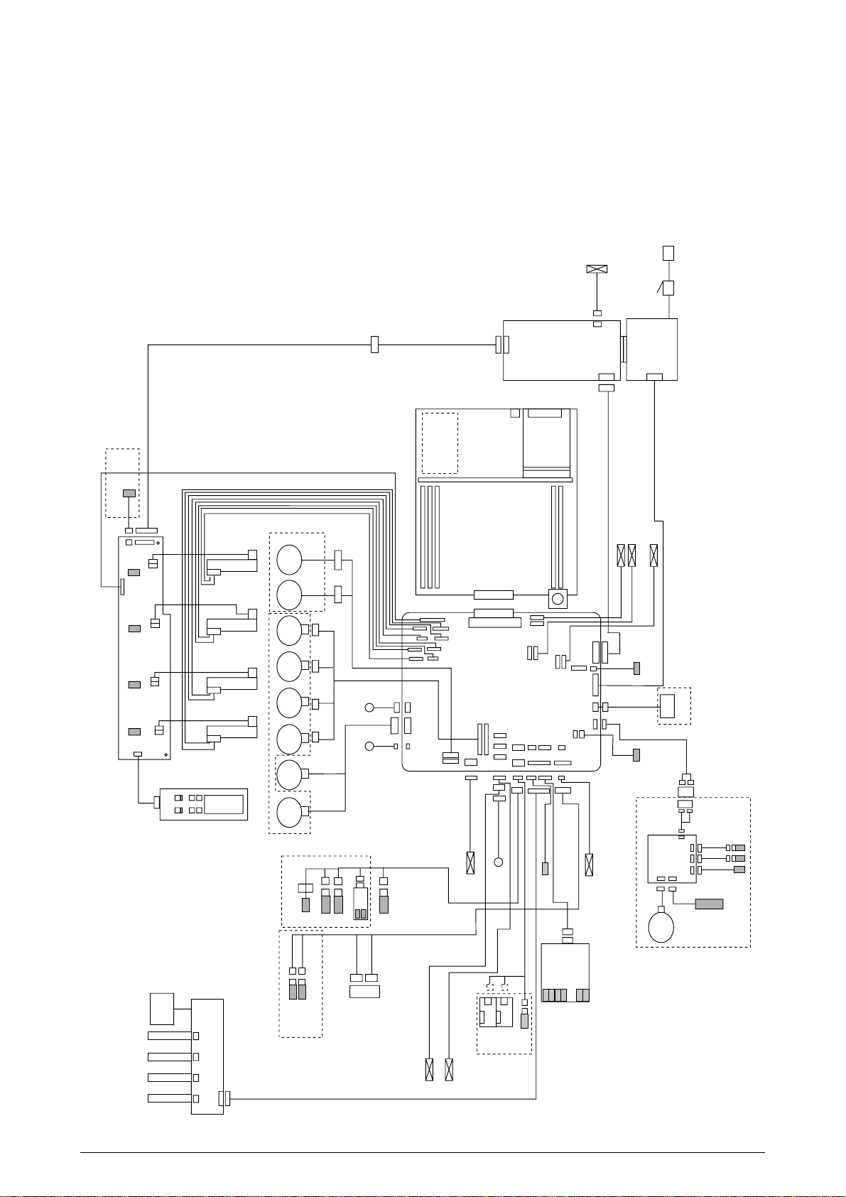
2. OPERATION DESCRIPTION
The C7500/C7300 of printers, tandem color electrophotographic page printers, adopt technologies
such as an LED array, OPC, dry single-component non-magnetic developing, roller transfer and
heat-compression fusing. A black-writing printing method by shedding light on print areas is used.
Figure 2-1-1(600dpi) provides the block diagram of the printer.
AC
FAN0
Sns.
STUCKFULL
14P
3P
POWER
STUCK
TNRC
3P
CPOW2
16P
OPTN
TNRM
MPOW2
3P3P3P
TNRY
YPOW2
TNRK
Toner Sensor (Y73-board)
KPOW2
PANEL
6P
6P
Belt
Fuse
C Fuse
M Fuse
Y Fuse
K Fuse
N71 Board
14P
JODEN
C LED HEAD
M LED HEAD
Y LED HEAD
K LED HEAD
Control Panel
X7N board
Heat
Motor
Belt
Motor
Motor
C IDU
Motor
M IDU
Motor
Y IDU
Main Motor Assy Belt Motor Assy
Motor
K IDU
Motor
FF/Regist
Motor
Hopping
2
Up/Down
Manual Bypass Feeder (MBF)
WHITE
BLUE
3P
3P
Paper Tray 1 Paper Empty
Paper Tray 2 Near Empty
WHITE YELLOW
46
Exit solenoid
BLACK YELLOW RED BLUE
4P 4P 4P 4P
shutter clutch
Cord 7
RED WHITE
4P 4P
4P
green
HUM
TEMP
OHP Sen.
MBF Paper Empty
BLUE
OPTION
7P
MBF Stage
Figure 2-1-1 600dpi
3P
AC Switch
CN5
10
HDD
RAM
10P
TIG board
CN2
USB
CENTRO
LAN
ROM
Low-voltage
power supply
26P
CN3
CN2
FAN(LEFT)
FAN
High -voltage
power supply
16P
FAN
CN1 CN1
FAN
OPTN
C1200
M1200
MPOW
K1200
KPOW
2P
DCL
red
red
8P
yellow
yellow
HOPFF
2P
SHUTTER
4P
yellow
Paper
thickness
YELLOW
7P
CPOW
CUIF
Y1200
YPOW
PCB-K7N
ID
16P
8P
FAN8
red
BEL THET
red
3P3P
3P
2P
Regist
Gray
FAN2
FAN1
red
RCL
yellow
red
yellow
clutch
14P
Blue
16P
FAN7
RSNS
REG
blue
blue
PARTTEMP
10P
14P
red
black
FAN4
2P
3P
yellow
yellow
FAN5
FSENS
JODEN
9P
22P
Exit sensor
9P
HOP(INSNS1)
PAPIN(INSNS2)
PSWR(WRSNS)
TNRFUL
FCOVER
FEED
TR10P
4P
R71 board
yellow
COVOPN
PSIZE
cable40
POWER
HVOLT
DUPLEX
3P
16P
6P
16P
26P
3P
Duplex Unit
Upper Cover
Open Microswitch
Open
Front Cover
V71 Board
Motor
DUP
Microswitch
Main
Clutch
7P
7P
BLUE
Paper Size
PXC-Board
BLUE
WHITE
7P
7P
14P
RSENS
FSENS
INSENS
Sensor
WHITE
5P
Z7L
Z7R
Plate Senosr
Density
FAN1 (Pr)
FAN2 (Pow)
12 /
Page 13
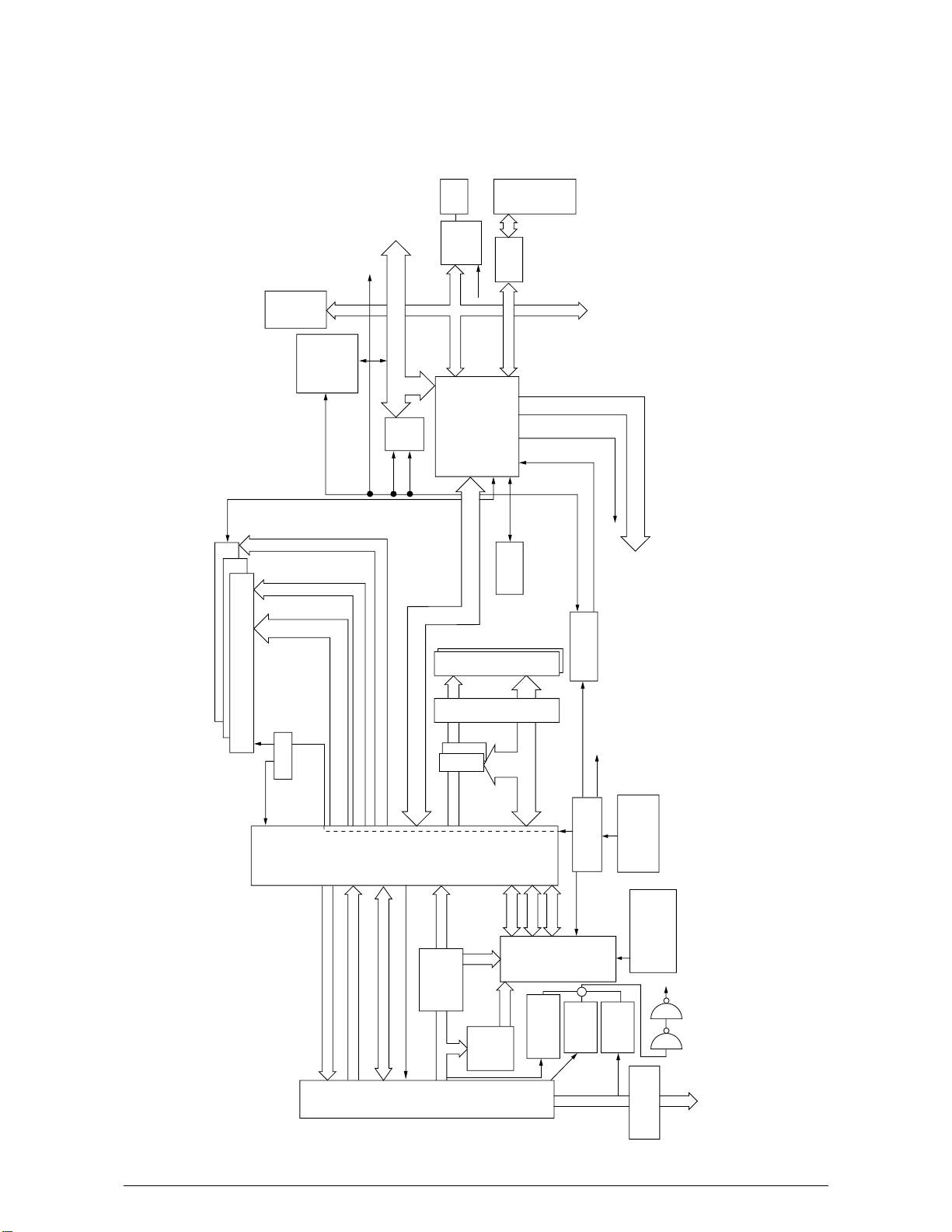
2.1 Main Board (TIG PWB)
Figure 2-2 provides the block diagram of the main control board (TIG PWB).
USB
t
r
o
n
e
C
[1]
[2]
[0]
SPD
3
2
1
3
×
12
×
3.3V 100MHz
SDRAM DIMM
SDRAMCLK
C2516
3.3V
DRCLK
100MHz
IDE
HDD
FPGA
for IDE
33MHz
RAMCLK
From 702
L60851
33MHz
[15:0][7:0]
PCI
Reset
CENT
[15:0]
Local
48MHz
LVC
161284
PCI BUS [31:0]
PCI
Slot
C2 LSI
MHM2031-002
33MHz
SUB Bus
EEPROM
×
2
D [63:0]
b Line Address. Cont
a Line Address. Cont
×
2
Flash
SUB Bus A/D [31:0], Cont
A,Cont
D
[15:0]
Mask 32bit
D [63:0] D [63:0]
4
×
33MHz 3.3V
33MHz 3.3V
5
×
ROM DIMM
PLL102-5
33MHz
33MHz
2.5V
100MHz
CA1CLK
to PU Panel I/F
to PU PU-CU Command I/F
48MHz
to USB
Crystal
MHM
CA1 LSI
Video Data K, Y, M, C
11N7)
(uPD856
2030-003
Video I/F From PU
Panel I/F From C2 LSI
PU-CU I/F To C2 LSI
Core:2.5V
200
PU-CU
I/O:3.3V
CPU I/O:2.5V
2.5V
2.5V
2.5V
Regulator
3.3V
pin
D [63:0]
A [31:0]
I/O 2.5V
1.8V
Reset IC
1.8V
Regulator
Cont
PPC
750cx
Core:1.8V
+
(PU3V)
PST596
M62733ML
12V
5V
PLL702-01
2.5V
MPUCLK
I/O:2.5V
(PU12V)
Resonator
14.31818MHz
100MHz
internal
CPU CLK
(+5V)
PST596
3.3V
Regulator
setting Resister
to each LSI
74LVC04
3.3V
Figure 2-2
13 /
Page 14

(1) CPU
The CPU is PowerPC750CXe, a 64-bit bus RISC processor, which inputs an 100-MHz CLK
(= BUS CLK), and operates at 450MHz that is 4.5 times the input.
(2) Cache
PPC750Cxe has its cache only inside of it.
Speed: Same as CPU Core CLK speed
Capacity:
Primary Cache: 32 K bytes in D-cache capacity, 32 K bytes in I-cache capacity
Secondary Cache: 256 K bytes
(3) ROM
ROM is to be inserted into the two 168 pin DIMM slots. The slot A is for program ROM and
the slot B is for Japanese kanji fonts. The slot C is not assigned.
(4) RAM
RAM is to be inserted into the three 168 pin DIMM slots. The DIMMs must be fitted in
descending labeled type No. order into the slots 1, 3, 2 and 4.
SDRAM DIMM Specifications:
Speed: PC133 or more
Capacity: 64/128/256/512 MB
Configuration: Without parity. Without ECC. SPD information is required.
(5) EEPROM
EEPROM, an 8-pin DIP package, is to be inserted into the IC socket. The EEPROM is of 16
Kbits for 3.3V power supply, and settings for controlling the controller block are stored in it.
(6) Flash ROM
A 4Mbyte flash ROM is surface-mounted on the TIG board. The flash ROM is composed of
four 2048k-by-16bit chips, and fonts and macros can be stored in it.
(7) Memory Control LSI (CAI)
A 696-pin BGA package ASIC made by NEC. The chip mainly controls a CPU I/F, memory,
video data compression and decompression, and a PU-video I/F.
(8) Interface Control LSI (C2)
A BGA package ASIC made by Toshiba, which controls a PU command I/F, operator panel
I/F, IDE I/F, Centronics I/F, USB I/F, PCI I/F, EEPROM and a SPD (SDRAM DIMM) I/F.
(9) IDE HDD
An IDE connector is surface-mounted on the board to which an IDE HDD assembled using
exclusive molds will be connected. The IDE HDD is used for storing font data, spooling edited
video data and registering form data.
(10) PCI Bus Option
Two PCI I/F slots are provided for option board use. The bus, which uses an Oki Data original
connector, can accept an Ethernet board.
(11) Host Interface
Standard: Centronics two-way parallel I/F (IEEE-1284-compliant)
USB (USB1.1-compliant)
Additional Board: (connected to PCI BUS) Ethernet Board
14/
Page 15

2.2 Engine Controller Board (K7N PWB)
28MHz
OPTION TRAY
PAPER THICKNESS
SENSOR
COROR REGISTRATION
SENSOR
HEAT ROLLER TEMP
OHP
TEMPATURE
HUMIDITY
HEAD TEMP
DENSITY
COVER OPEN
(UPPER, STACKER, RIGHT SIDE)
1ST TRAY SENSORS
(PAPER END, PAPER NEAR END)
PAPER FEED SYSTEM SENSORS
(PAPER FEED, PAPER
REGISTRATION, EJECT)
MT SENSORS
(STAGE POSITION, PAPER END)
DUPLEX
DISPOSAL TONER SENSOR
ANALOG
SW
CPU
MSM66Q577
PAPER SIZE
STACKER FULL
CU
INT
CLK
RESET
FLASH
SRAM
MCON
LSI
EEPROM
CONTROL
PANEL
MOTOR
DRIVER
MOTOR
DRIVER
PULSE
MOTOR *9
GEARED
MOTOR
CLUTCH
PU FAN
FUSER FAN
ID, BELT,
FUSER
CHECKS
HIGH VOLTAGE POWER
SUPPLY SERIAL INTERFACE
32MHz
CLOCK
GENERATOR
LED HEAD (K)
LED HEAD (Y)
LED HEAD (M)
LED HEAD (C)
SDRAM
SDRAM
DCON
LSI
Figure 2-3
The engine control block (PU) is controlled by the engine controller board (K71 PWB) which
consists of a CPU (MSM66Q577), general LSI chip, flash ROM, EEPROM, pulse motor drivers and
a video memory (see Figure 2-3).
(1) CPU
This, a 16-bit CPU with an AD converter (OKI MSM66Q577), controls the entire system.
(2) General LSI
This LSI (UPD65454GD-241-LML, UPD65946GD-137-LML), which is contained in the
printer engine control block, incorporates 4 megabits of video memory and has functions
such as engine-controller interfacing, LED interfacing, motor control, sensor input, video
memory control, main scan color misalignment correction, skew correction and high-voltage
power supply control.
15/
Page 16

(3) MCON LSI
This LSI is used for inport of SENSORs and the cntrols of Pulse Motors,Cluches,FANs and
High Voltage Power Suply.
(4) Flash ROM
The flash ROM (29F800-70) is of 8-Mbits, and PU programs are stored in it.
(5) EEPROM
The EEPROM (NM93C66N-NW) is of 4-Kbits, and mounted on the board with an IC socket.
Correction values are stored in it.
(6) Pulse Motor Driver
The pulse motor driver (A2919SLBTR, A3955SLBTR,MTD2005) drives the eight pulse
motors to revolve the ID and transport media.
(7) SRAM
This SRAM (628100LG-55L) is used as working memory of the CPU.
(8) SDRAM
This SRAM (56V16160T) is used as data memory of the DCON LSI.
2.3 Power Units
There are a low voltage power unit consists of an AC filter circuit, low voltage power circuit and
heater driver circuit, and a high voltage power unit organizes a high voltage power circuit.
(1) Low Voltage Power Unit
This circuit generates the following voltages:
Output Voltage Use for
+5 V LED head
+5 V Logic circuit power supply, PU CPU
+34 V Motor, drive voltage and power supply voltage for high voltage power supply
+12 V High voltage power supply, Media Thickness Sensor power supply
(2) High Voltage Power Unit
This circuit generates the following voltages of not less than +34V, which are required for
electrophotographic process, according to control sequences from the controller board.
Output Voltage Use for Remark
CH -1000V to 1.4KV+/-50V Voltage to charging roller
DB -50 to -300V/ +300V Voltage to developing roller
SB -300V to -450V/ 0V Voltage to toner supplying roller
TR C: 0KV to 7KV Voltage to transfer roller Variable
K,Y,M: 0KV to 6KV
16/
Page 17

2. PARTS REPLACEMENT
This section describes the procedure for replacing the parts, assemblies and units in the field. The
replacing procedure is given for detachment. To attach, use the reverse procedure.
2.1 Precautions in Replacing Parts
(1) Before replacing the parts, be sure to remove the AC cable and the interface cable.
(a) To remove the AC cable, always use the following procedure.
i) Flip the power switch of the printer off (to “O”).
ii) Pull the AC inlet plug of the AC cable out of the AC receptable.
iii) Remove the AC cable and the interface cable from the printer.
(b) To connect the printer again, always use the following procedure.
i) Connect the AC cable and the interface cable to the printer.
ii) Insert the AC inlet plug into the AC receptacle.
iii) Flip the power switch of the printer on (to “I”).
Disconnect
(2) Do not disassemble the printer so long as it operates properly.
(3) Minimize the disassembly. Do not detach parts other than those shown in the replacing procedure.
(4) For maintenance, use designated tools.
(5) Follow the order instructed to disassemble the printer. Incorrect order may damage the parts.
(6) Small parts such as screws and collars tend to get lost, so temporarily place and fix them in
(7) When handling ICs and circuit boards such as microprocessors, ROMs and RAMs, do not use
Connect
their original positions.
gloves that likely to have static.
(8) Do not place the printed circuit boards directly on the printer or the floor.
17 /
Page 18
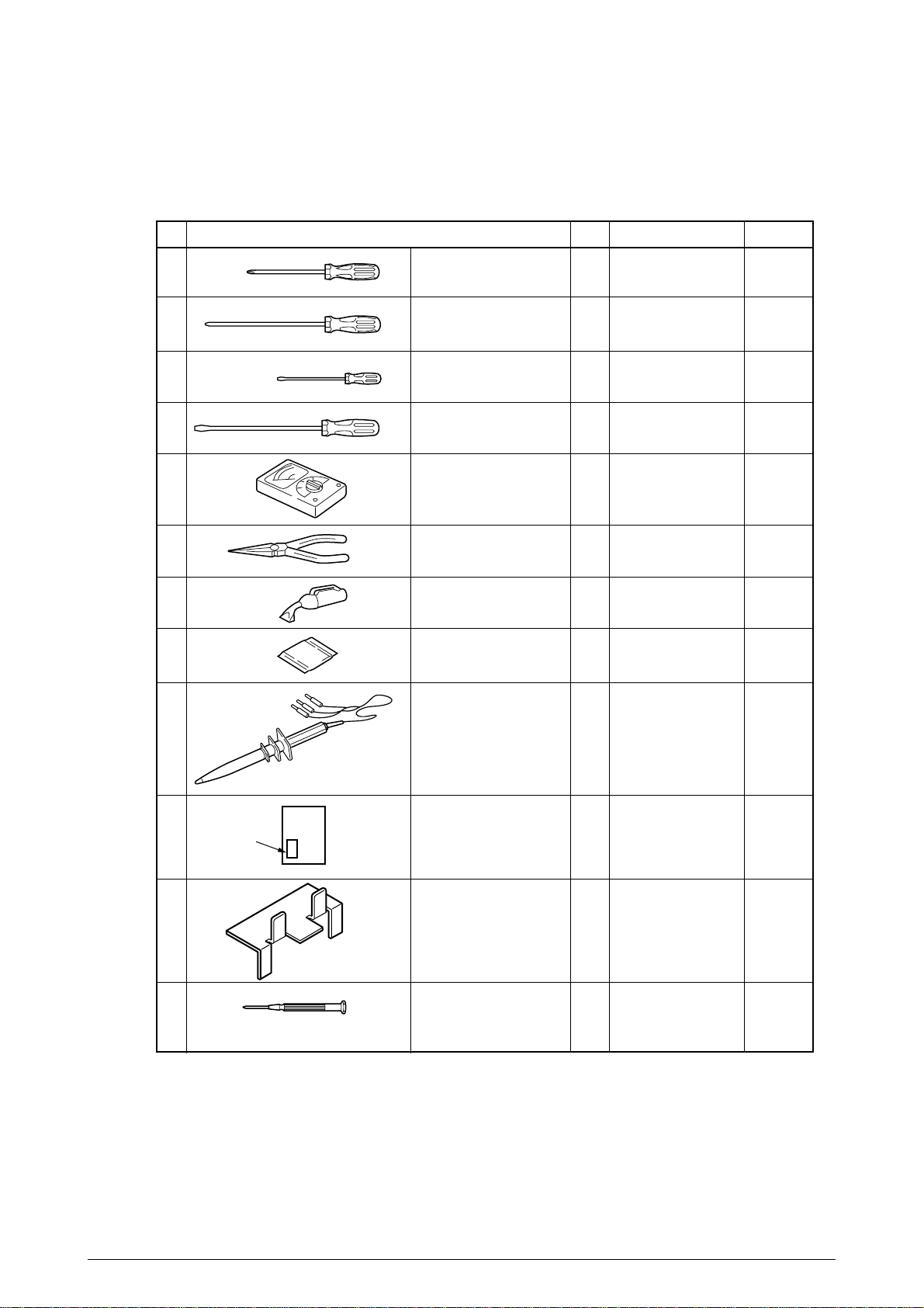
[Maintenance Tools]
Table 2-1 lists tools necessary to replace the printed circuit boards and the units.
Table 2-1 Maintenance Tools
No.
1
2
3
4
5
6
7 1
8
No. 1-100 Philips
screwdriver
No. 2-200 Philips
screwdriver, Magnetized
No. 3-100 screwdriver
No. 5-200 screwdriver
Digital multimeter
Pliers
Handy cleaner
LED Head cleaner
Q' ty Place of use RemarksService Tools
1
2~2.5 mm screws
1
3~5 mm screws
1
1
1
1
1
9 1
10
Label
11
12
High voltage probe
Transparency sheet
( thickness premeasured)
0ZZ42404301//
Stage height adjustment jig
0ZZ42423701//
-
Microdriver
2.0mm
1
Adjustment for Media
Thickness sensor
1
Adjustment for Media
Thickness sensor
1
Adjustment for Lever
adjust
(Media Thickness)
18 /
Page 19
2.2 Parts layout
B
A
A
B
B
A
A
Figure 2-1
19 /
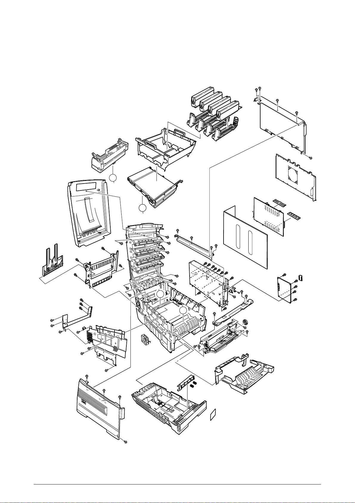
Page 20
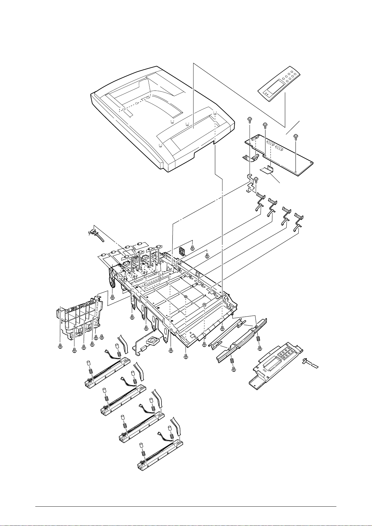
[Top Cover Assy]
Figure 2-2
20 /
Page 21

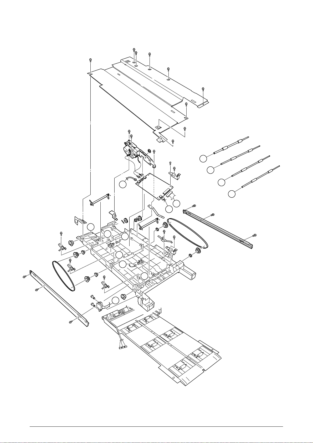
[Printer Unit-1/2]
Figure 2-3
A
A
21 /
Page 22
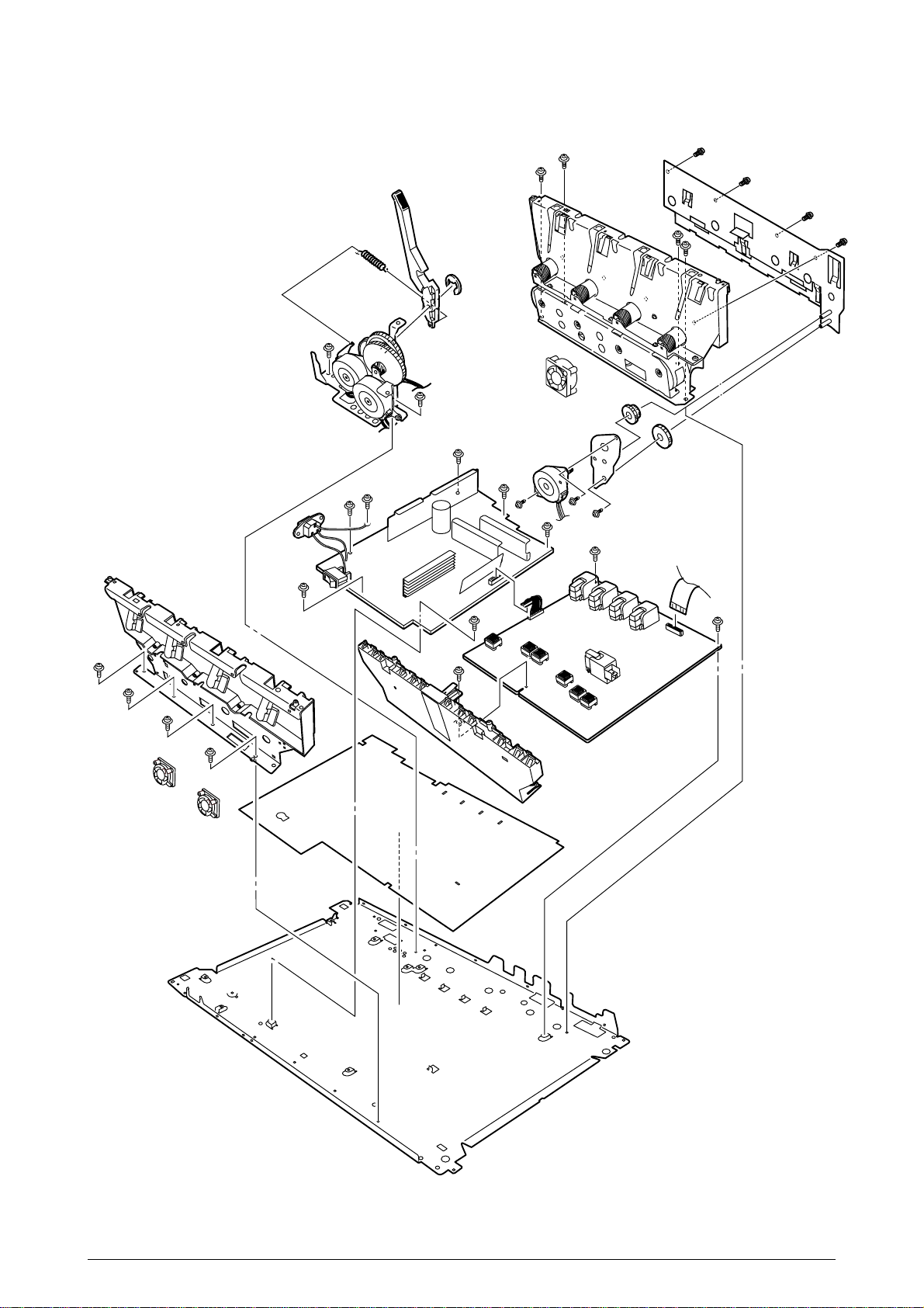
[Printer Unit-2/2]
Figure 2-4
22 /
Page 23

[Cassette Guide Assy (L),(R)]
B
A
C
C’
A
B
C
C’
Figure 2-5
23 /
Page 24
[Duplex Unit]
D
C
G
B
A
E
F
D
C
G
B
F
A
E
Figure 2-6
24 /
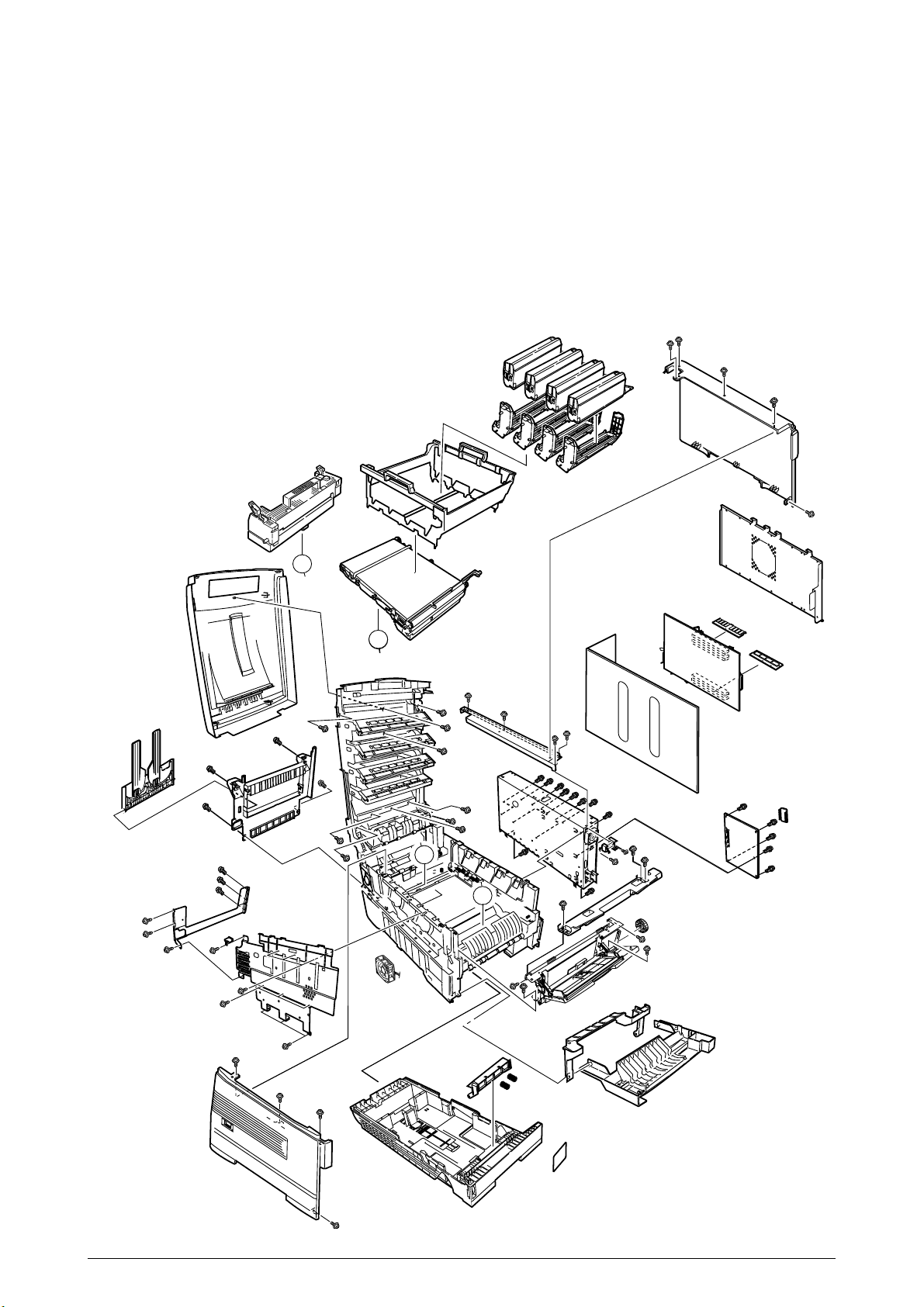
Page 25

2.3 Replacing Parts
This section describes how to replace the parts and assemblies shown in the following disassembling system diagram.
AR-C200P
Print Engine Controller PWB (2.3.23)
x 4
LED Assy (2.3.2)
Low Voltage Power Supply (2.3.36)
High Voltage Power Supply (2.3.37)
0ZZ41940001//
Printer NIP
-
0ZZ40839001//
Left Cassette Guide Assy (2.3.40)
0ZZ40839406//
Right Cassette Guide Assy (2.3.41)
0ZZ40839801//
Main Feed Assy (2.3.39)
0ZZ40844306//
Regist Roller Assy (A) (2.3.17)
0ZZ41940201//
Printer Unit
0ZZ41128101//
Insurator
0ZZ42153101//
Main Cooling Fan Assy (2.3.20)
2381023P0003
HV Tape Harness
40847306
Main Motor Assy (2.3.34)
40848801
Transport (Transfer) Belt Motor Assy (2.3.32)
0ZZ40850201//
Contact Assy (2.3.36)
0ZZ41303606//
Left Plate Assy (2.3.36)
0ZZ40864301//
Rear Cover (2.3.10)
0ZZ40864411//
Left Side Cover (2.3.12)
0ZZ40864503//
Right Side Cover (2.3.13)
0ZZ40864601//
Front Cover Assy (2.3.7)
41042501
Front Cover Inner Baffle (2.3.7)
0ZZ41374902//
Face Up Tray (2.3.11)
0ZZ40864901//
Frame Assy - Release
A
0ZZ40371302//
Feed Roller (2.3.9)
0ZZ40325401//
Main Feeder Drive Gear (2.3.39)
0ZZ40313202//
Nudger Roller (2.3.9)
0ZZ41940301//
Printer Chassis (2.3.17)
0ZZ40844307//
Regist Roller Assy (B) (2.3.18)
0ZZ40845801//
Registration Motor Assy (2.3.19)
0ZZ41187102//
Registration Clutch (2.3.19)
0ZZ40859201//
Duplex Guide Assy (2.3.22)
0ZZ40848501//
Main Feeder Drive Gear A (2.3.35)
0ZZ40848601//
Main Feeder Drive Gear B (2.3.35)
0ZZ40846001//
Main Feeder Motor (2.3.35)
0ZZ40841401//
Fuser Latching Handle (R) (2.3.33)
0ZZ40841501//
Fuser Latching Handle Spring (2.3.33)
Plastic Slide (2.3.41)
0ZZ40349101//
Cassette Guide Pivot (L) (2.3.41)
0ZZ40349701//
Plastic Roller (2.3.41)
0ZZ40928101//
Cassette Spring (2.3.41)
Cassette Lock (2.3.41)
Cassette Lock Spring (2.3.41)
Foot (2.3.41)
0ZZ40368304//
Paper Size Sensing PWB PXC (2.3.41)
0ZZ50928901//
Paper Size Actuator (2.3.41)
0ZZ41143701//
Duplex Assy Ground contact (2.3.41)
0ZZ41309106//
2nd Tray Connector (2.3.41)
0ZZ41285701//
Plate Assy-SW(Front) (2.3.41)
Plastic Slide (2.3.40)
0ZZ40349102//
Cassette Guide Pivot (R) (2.3.40)
0ZZ40349701//
Plastic Roller (2.3.40)
0ZZ40928101//
Cassette Spring (2.3.40)
Cassette Lock (2.3.40)
Cassette Lock Spring (2.3.40)
Foot (2.3.40)
0ZZ41275901//
Microswitch-Assy (2.3.41)
0ZZ40841301//
Fuser Latching Handle (L) (2.3.31)
0ZZ40841501//
Fuser Latching Handle Spring (2.3.31)
0ZZ40841601//
Entrance Sensor Actuator #1 (2.3.26)
0ZZ40841701//
Entrance Sensor Actuator #2 (2.3.28)
0ZZ40841801//
Entrance Senspr Actuator #3 (2.3.28)
0ZZ42199601//
Waste Toner Sensor Actuator (2.3.28)
0ZZ41253601//
Duplex Gate solenoid Assy (2.3.29)
0ZZ41968701//
Registration Shutter Solenoid Assy
0ZZ41944201//
Registration Shutter
0ZZ41968501//
Registration Shutter Spring
0ZZ42170801//
Fuser Drive Gear-C (2.3.29)
0ZZ40323902//
Fuser Exit Roller (2.3.29)
0ZZ40316301//
Fuser Drive Gear-B (2.3.29)
Fuser Exit Roller Bushing (L) (2.3.29)
Fuser Exit Roller Bushing (R) (2.3.29)
0ZZ41189701// x 4
Drum Contact Assy (2.3.15)
0ZZ41258301//
Entrance Sensor PWB (2.3.27)
0ZZ41312801//
Left Top Cover Spring Assy (2.3.25)
0ZZ41312901//
Right Top Cover Spring Assy (2.3.25)
0ZZ41944001//
Color Registration Sensor Assy (2.3.21)
0ZZ41073601//
Exit Sensor Assy (2.3.30)
25 /
Page 26
A
0ZZ41911201//
Thickness Plate Assy
0ZZ41928801//
Stage-Pickup
0ZZ41888701//
Cover-Seal-Sensor
0ZZ41911101//
Thickness Sensor Assy
CU Board Assy
0ZZ41940701//
Cover Assy Stacker
0ZZ40862006//
Multipurpose Feeder Assy (2.3.14)
0ZZ40952701//
Multipurpose Tray Top Cover (2.3.14)
0ZZ40866701//
Cassette Assy (2.3.8)
Board Assy-CU
0ZZ40859702//
Top Cover (2.3.1)
0ZZ41988101//
Cover-Assy-Inner (2.3.3)
0ZZ40325101//
Multipurpose Feeder Drive Gear (2.3.14)
0ZZ41045801//
Link (2.3.14)
4YB4120-1137P001
MT Paper Empty Sensor (2.3.14)
0ZZ41849401//
MT OHP Sensor (2.3.14)
0ZZ41276001//
MT Position Sensor (2.3.14)
0ZZ40866301//
Multipurpose Tray Cover Assy (2.3.14)
0ZZ41438401//
Retard Pad Assy (2.3.8)
0ZZ41439401//
Retard Pad Assy Spring (2.3.8)
⋅
2
⋅
2
Board_TIG
0ZZ41964009//
Board Assy.-CU(711)
0ZZ41278601//
Guide_Rail (A)
0ZZ41278701//
Guide_Rail (B)
0ZZ41410201//
Motor-Fan 60x60x15
0ZZ41723901//
Screw
PB4013-3100P006 x9
Cup Screw (S Tight M3)
P3-6G
Screw (Round Head)
Tapping Screw
Screw(Round Head, SW+2W)
0ZZ41467401//
Plate FG (Centronics)
0ZZ41254601//
Plate Blank
⋅
2
⋅
4
⋅
2
0ZZ41316501//
Top Cover Inner Frame Assy (2.3.4)
0ZZ42216201//
LED Assy Spring (2.3.2)
0ZZ41960901//
LED Control PWB (Y71) (2.3.4)
0ZZ40365404//
Stack Full Sensor (2.3.4)
0ZZ40860601//
Toner Sensor
0ZZ40866102//
Control Panel Assy (2.3.4)
2381003P0014
Control Panel Tape Harness (2.3.4)
0ZZ41409601//
LED Harness K (2.3.4)
0ZZ41309602//
LED Harness Y (2.3.4)
0ZZ41309603//
LED Harness M (2.3.4)
0ZZ41309604//
LED Harness C (2.3.4)
0ZZ40861501//
Eject Guide Assy (2.3.6)
PCB Assy_TIG
Board Memory 64MB
Board CRF
⋅
8
⋅
4
0ZZ40861201//
Top Cover Handle (2.3.5)
0ZZ40861301//
Top Cover Latch (2.3.5)
0ZZ40861401//
Top Cover Latch Spring (2.3.5)
⋅
2
26 /
Page 27
2.3.1 Top Cover
(1) Open the Top Cover assy.
(2) Remove the nine screws 1 to detach the top cover 2.
2
1
Figure 2-3-1 Top Cover
1
1
27/
Page 28
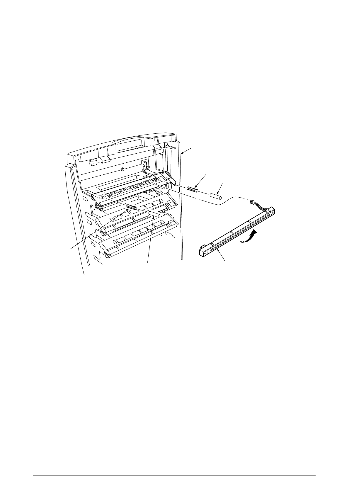
2.3.2 LED Head / LED Spring / Post-Guide
(1) Open the top cover 1.
(2) Remove the three cables, and unhook the LED Head 2 at two places to demount it (the two
springs 3, Post-Guide 4 become detached together with the LED Head 2).
1
3
4
3
4
Figure 2-3-2 LED Head / LED Spring / Post-Guide
2
28 /
Page 29
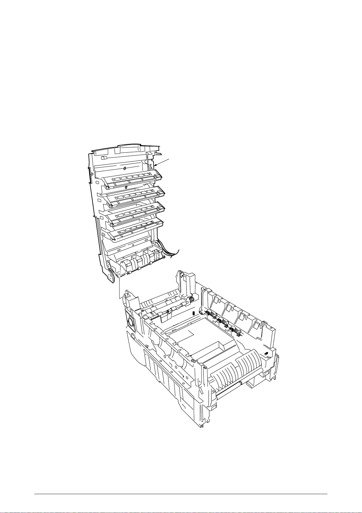
2.3.3 Top Cover Unit
(1) Remove the top cover (see section 2.3.1).
(2) Remove the rear cover (see section 2.3.10).
(3) Remove the left side cover (see section 2.3.12).
(4) Remove the right side cover (see section 2.3.13).
(5) Remove the shield plates A and B (see section 2.3.23), and unplug the connector to separate
the top cover.
(6) Disengage the top cover unit 1 at two places to detach it.
1
Figure 2-3-3 Top Cover Unit
29 /
Page 30
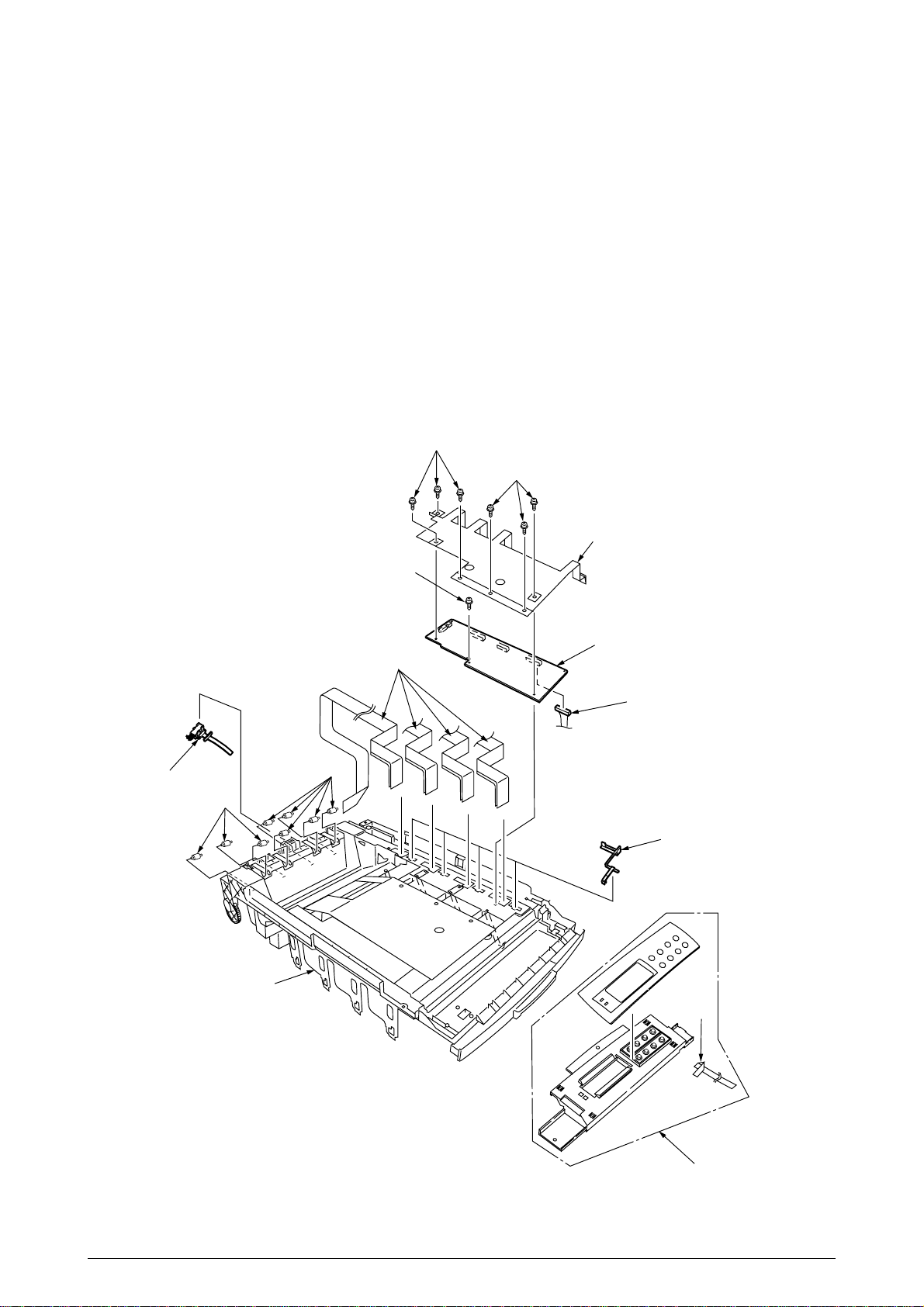
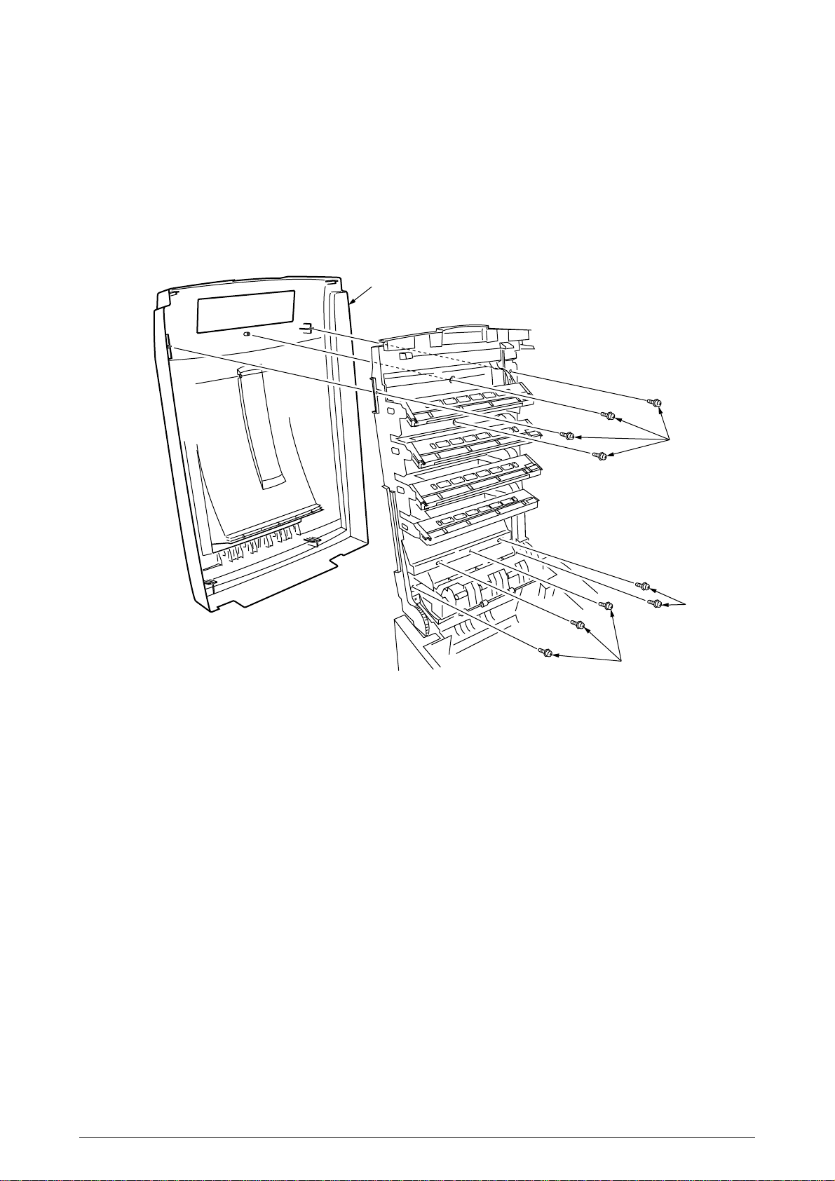
2.3.4 Control Panel Assy/ Control Panel Bezel/ LED Control PWB/ Toner Sensors/ Stacker Full Sensor/
Control Panel/ Control Panel Tape Harness/ Eject Rollers
(1) Remove the control panel Assy 1.
(2) Detach the control panel tape harness 2.
(3) Remove the top cover unit (see section 2.3.3).
(4) Unscrew the six screws 3 to remove the earth plate 4.
(5) Remove the two screws 5, unhook all the connectors 6 and demount the LED control PWB 7.
(6) Disengage the four claws to demount the toner sensor 8.
(7) Demount the stacker full sensor 9.
(8) Demount the exit rollers A.
(9) Detach the LED harnesses, K, Y, M and C B.
(10) Detach the top cover inner frame Assy C.
3
3
9
4
5
7
A
6
0
0
8
B
2
1
Figure 2-3-4 Control Panel Assy/ Control Panel Bezel/ LED Control PWB/ Toner Sensors/ Stacker
Full Sensor/ Control Panel/ Control Panel Tape Harness/ Eject Rollers
30 /
Page 31

2.3.5 Top Cover Handle/ Top Cover Latch/ Top Cover Latch Spring
(1) Remove the two screws 1 to detach the top cover handle 2 and disengage the top cover latch
3 (at the same time, the two top cover latch springs 4 become detached).
1
3
2
1
4
4
Figure 2-3-5 Top Cover Handle/ Tope Cover Latch/ Top Cover Latch Spring
31 /
Page 32

2.3.6 Eject Guide Assy
(1) Remove the five screws 1 to detach the eject guide Assy 2.
1
1
1
2
Figure 2-3-6 Eject Guide Assy
32 /
Page 33

2.3.7 Cassette Assy/ Front Cover Assy/ Front Cover Inner Baffle
(1) Detach the cassette Assy 1.
(2) Open the front cover 2, and disengage it at two places to detach it.
(3) Detach the front cover inner baffle 3.
3
1
Figure 2-3-7 Cassette Assy/ Front Cover Assy/ Front Cover Inner Baffle
2
33 /
Page 34

2.3.8 Retard Pad Assy/ Retard Pad Assy Spring
(1) Remove the cassette 1.
(2) Detach the retard pad Assy 2 (at the same time, the spring 3 becomes detached).
1
2
3
Figure 2-3-8 Retard Pad Assy/ Retard Pad Assy Spring
34 /
Page 35

2.3.9 Feed Roller and Nudger Roller
(1) Remove the cassette.
(2) Unlatch and demount the feed roller 1.
(3) Unlatch and demount the nudger roller 2.
2
1
Figure 2-3-9 Feed Roller and Nudger Roller
35 /
Page 36

2.3.10 Rear Cover
(1) Remove the left side cover (see section 2.3.12).
(2) Remove the four screws 1 to detach the rear cover 2.
Note!
When attaching the rear cover, take care not to allow the spring 3 to get caught in parts.
3
1
2
1
1
Figure 2-3-10 Rear Cover
36 /
Page 37

2.3.11 Face-Up Tray
(1) Open the face-up tray 1 in the arrow direction, and disengage it at two places to detach it.
Figure 2-3-11 Face-Up Tray
1
37 /
Page 38

2.3.12 Left Side Cover
(1) Open the top cover 1.
(2) Open the front cover 2 and undo the screw 3.
(3) Remove the four screws 4 to detach the left side cover 5.
4
1
4
4
5
Figure 2-3-12 Left Side Cover
3
2
38 /
Page 39

2.3.13 Right Side Cover
(1) Open the top cover 1.
(2) Open the front cover 2 and undo the screw 3.
(2) Remove the five screws 4 to detach the right side cover 5.
4
4
1
5
3
2
Figure 2-3-13 Right Side Cover
39 /
Page 40

2.3.14 Multipurpose Tray Assy/ Multipurpose Tray Cover Assy/ Links/ Multipurpose Tray Top Cover/
Multipurpose Tray Drive Gear
(1) Remove the left side cover (see section 2.3.12).
(2) Remove the right side cover (see section 2.3.13).
(3) Detach the Cover Seal Sensor and the Thickness Sensor Connector (see section 2.3.16).
(4) Remove the three screws 1 to detach the multipurpose tray top cover 2.
(5) Remove the three screws 3 (two of them are black) and the connector to detach the multipurpose
tray 4.
(6) Disengage A and B at both sides of the assembly to detach the multipurpose tray cover Assy
5 (at the same time, the links 6 become detached).
(7) Unhook and detach the multipurpose tray drive gear 7.
6
3
1
1
7
2
4
6
3
3
B
B
A
7
A
5
Figure 2-3-14 Multipurpose Tray Assy/ Multipurpose Tray Cover Assy/ Links/ Multipurpose Tray Top
Cover/ Multipurpose Tray Drive Gear
40 /
Page 41

2.3.15 Drum Contact Assys
(1) Insert a flatblade screwdriver between the printer case and the drum contact Assy 1 to demount
the drum contact Assy 1.
1
Figure 2-3-15 Drum Contact Assys
41 /
Page 42

2.3.16 Media Thickness Sensor Assy
(1) Detach the Cover Seal Sensor 1 and the Thickness Sensor Connector 2.
(2) Remove the two screws 3 to demount the Media Thickness Assy.
(3) Insert a microdriver(-) between the Thickness Plate Assy 4 and Thickness Sensor Assy 5 to
demount the Thickness Sensor Assy 5
Note!
When attaching the Media Thickness Assy, adjust [Spin lever adjust by microdriver(-)] the
position of lever (White).
The upper surface of the lever be in agreement with a datum level. (Adjustment range 0/-
0.5mm)
Lever(White)
0/-0.5mm
Adjustment
range
View A
Datum
level
1
Datum
level
Lever(White)
Microdriver
2
View A
3
5
3
Lever
adjust
4
Figure 2-3-16 Media Thickness Sensor Assy
42 /
Page 43

2.3.17 Registration Roller Assy (A)/ Registration Drive Gear (A)
(1) Remove the left side cover (see section 2.3.12).
(2) Remove the right side cover (see section 2.3.13).
(3) Remove the multipurpose tray (see section 2.3.14).
(4) Remove the Media Thickness Sensor Assy. (see section 2.3.16).
(5) Remove the screw 1 of the Pickup Stage 2.
(6) Remove the four screws 3 to demount the registration roller Assy (A) 4and the Pickup Stage
2.
(7) Remove the E ring 5 to detach the registration gear (A) 6.
Note!
Stage height adjustment jig
1
Top surface
Stage height adjustment jig
When attaching the pickup stage 2, place the stage height adjustment jig between the
pressure roller and the registration roller and, until the top surface of the pickup stage
reaches the jig, move the pickup stage toward the jig.(See Table 2-1 Maintenance Tools)
Top surface
3
1
2
4
3
6
5
Figure 2-3-17 Registration Roller Assy (A)/ Registration Driver Gear (A)
43 /
Page 44

2.3.18 Registration Roller Assy (B)
(1) Remove the cassette Assy.
(2) Open the front cover.
(3) Remove the right side cover (see section 2.3.13).
(4) Remove the left plate Assy (see section 2.3.23).
(5) Remove the registration clutch (see section 2.3.19).
(7) Unscrew the four screws 1, and pull out the registration Assy (B) 1 in the arrow direction.
2
1
1
1
Figure 2-3-18 Registration Roller Assy (B)
44 /
Page 45

2.3.19 Registration Clutch and Registration Motor Assy
(1) Remove the left side cover (see section 2.3.12).
(2) Remove the left plate Assy (see section 2.3.23).
(3) Remove the connector and the E ring 1, then remove the two screws 2, the earth 3 and the
registration clutch 4.
(4) Remove the connector to remove the two screws 5 and the registration motor Assy 6.
5
4
Figure 2-3-19 Registration Clutch and Registration Motor Assy
6
5
2
3
2
1
45 /
Page 46

2.3.20 Main Cooling Fan
(1) Unhook the connector 1, and remove the screw 2 and the cooling fan 3.
Note!
When attaching the cooling fan, observe its correct orientation.
Figure 2-3-20 Main Cooling Fan
Outlet
3
1
2
46 /
Page 47

2.3.21 Color Registration Sensor Assy
(1) Remove the two screws 1 and the two connectors to demount the color registration sensor
Assy 2.
(2) Remove the earth plate B 3.
1
1
2
3
Connectors
Figure 2-3-21 Color Registration Sensor Assy
47 /
Page 48

2.3.22 Duplex Guide Assy
(1) Unlatch and demount the duplex guide 1.
1
Main chassis (rear)
Figure 2-3-22 Duplex Guide Assy
48 /
Page 49

2.3.23 Electrical Chassis Cooling Fan
(1) Unscrew the four screws 1 to remove the plate A 2.
(2) Unscrew the thirty-four screws 3 to remove the shield plate B 4.
(3) Remove the printer engine controller PWB (see section 2.3.24).
(4) Unscrew the eleven screws 5 to remove the shield plate 6.
(5) Unscrew the two screws 7 to demount the electrical chassis cooling fan 8.
1
1
7
8
6
2
4
5
5
3
5
Outlet
5
3
Figure 2-3-23 Electrical Chassis Cooling Fan
49 /
Page 50

2.3.24 Printer Engine Controller PWB
(1) Remove the right side cover (see section 2.3.13).
(2) Remove the left plate Assy (see section 2.3.23).
(3) Remove the five screws 1 and all the connectors to demount the printer engine controller
PWB 2.
2
Figure 2-3-24 Printer Engine Controller PWB
1
1
50 /
Page 51

2.3.25 Printer Unit Chassis
(1) Unscrew the two screws 1 and remove the AC inlet 2.
(2) Unscrew the four black screws 3 and five screws 4 to detach the printer unit chassis 5.
(3) Unscrew the four black screws 6 and remove the left top cover spring Assy 7.
(4) Unscrew the four black screws 8 and remove the right top cover spring Assy 9.
6
6
3
7
4
4
3
4
9
3
5
8
8
4
3
2
1
Figure 2-3-25 Pinter Unit Chassis
51 /
Page 52

2.3.26 Entrance Cassette Sensor Actuator
(1) Remove the printer unit chassis (see section 2.3.25).
(2) Turn over the main chassis.
(3) Remove the two clamps with tweezers to demount the entrance cassette sensor actuator 1.
1
Main chassis
Figure 2-3-26 Entrance Cassette Sensor Actuator
52 /
Page 53

2.3.27 Entrance Sensor PWB
(1) Remove the registration roller Assy (B) (see section 2.3.18).
(2) Remove the two screws 1 to demount the entrance sensor PWB 2.
Figure 2-3-27 Entrance Sensor PWB
1
2
53 /
Page 54

2.3.28 Entrance MT Sensor Actuator / Entrance Belt Sensor Actuator / Entrance Waste Chassis Sensor
Actuator
(1) Remove the entrance sensor PWB (R71) (see section 2.3.27).
(2) Unlatch and detach the entrance MT sensor actuator 1.
(3) Unlatch and detach the entrance belt actuator 2.
(4) Release the latch and remove the Entrance Waste Chassis Sensor Actuator 3.
2
1
3
Figure 2-3-28 Entrance MT Sensor Actuator / Entrance Belt Sensor Actuator /
Entrance Waste Chassis Sensor Actuator
54 /
Page 55

2.3.29 Fuser Exit Roller
(1) Unscrew the two screws 1 to remove the duplex gate solenoid Assy 2.
(2) Unscrew the screw 3 to remove the fuser exit roller contact 4.
(3) Remove the fuser drive gear -A 5 and fuser drive gear -A 6.
(4) Unscrew the screw 7 to remove the fuser drive gear -C 8.
(5) Unlatch and detach the fuser drive gear -B 9 and fuser exit roller bush (R) 0.
(6) Unlatch and detach the fuser exit roller bush (L) A and fuser exit roller B.
B
A
1
7
8
0
9
6
5
3
4
2
Figure 2-3-29 Fuser Exit Roller
55 /
Page 56

2.3.30 Exit Sensor Assy
(1) Remove the fuser exit roller (see section 2.3.29).
(2) Remove the screw 1 and connector to demount the (red and blue) exit sensor Assy 2.
1
2
Figure 2-3-30 Exit Sensor Assy
56 /
Page 57

2.3.31 Fuser Latching Handle (L)
(1) Remove the latching handle spring 1.
(2) Unscrew the screw 2 to detach the fuser latching handle (L) 3.
3
1
2
Figure 2-3-31 Fuser Latching Handle (L)
57 /
Page 58

2.3.32 Belt Motor Assy
(1) Remove the fuser latching handle (R) (see section 2.3.33).
(2) Remove the two screws 1 to detach the two connectors 2.
(3) Demount the belt motor Assy 3.
1
3
1
2
Figure 2-3-32 Belt Motor Assy
58 /
Page 59

2.3.33 Fuser Latching Handle (R)
(1) Remove the printer unit chassis (see section 2.3.25).
(2) Remove the E ring 1.
(3) Remove the fuser latching handle spring 2 to detach the fuser latching handle (R) 3.
3
2
1
Figure 2-3-33 Fuser Latching Handle (R)
59 /
Page 60

2.3.34 Main Motor Assy
(1) Remove the belt motor Assy (see section 2.3.32).
(2) Remove all the connectors.
(3) Remove the four screws 1 to demount the main motor Assy 2.
1
2
1
1
Figure 2-3-34 Main Motor Assy
60 /
Page 61

2.3.35 Main Feeder Drive Motor
(1) Remove the two screws 1 to detach the main feeder drive motor 2.
(2) Unscrew the screw 3 to remove the main feeder drive motor bracket 4.
(3) Remove the main feeder drive motor gears A 5 and B 6.
1
5
2
6
4
1
3
Figure 2-3-35 Main Feeder Drive Motor
61 /
Page 62

2.3.36 Contact Assy/ Left Plate Assy
(1) Remove the printer unit chassis (see section 2.3.25).
(2) Remove the four screws 1 to detach the left plate Assy 2.
(3) Remove the screw 3 to detach the contact Assy 4.
4
2
3
1
1
Figure 2-3-36 Contact Assy/ Left Plate Assy
62 /
Page 63

2.3.37 Low Voltage Power Supply
(1) Remove the printer unit chassis (see section 2.3.25).
(2) Unhook the connector 1.
(3) Unscrew the screw 2 to remove the earth cable 3.
(4) Unscrew the six screws 4 to demount the low voltage power supply 5.
1
4
2
4
3
5
4
Figure 2-3-37 Low Voltage Power Supply
63 /
Page 64

2.3.38 High voltage power supply
(1) Remove the contact Assy (see section 2.3.36).
(2) Unhook the connector of the high voltage power supply 1.
(3) Remove the two screws 2 to detach the high voltage power supply 1 and the tape harness 3.
2
3
1
2
Figure 2-3-38 High Voltage Power Supply
64 /
Page 65

2.3.39 Main Feed Assy
(1) Remove the printer unit chassis (see section 2.3.25).
(2) Remove the low voltage power supply and high voltage power supply (see sections 2.3.37 and
2.3.38).
(3) Unscrew the five screws 1 to remove the lower plate 2.
(4) Unscrew the four screws 3 to demount the main feed Assy 4.
(5) Unhook and remove the main feed drive gear 5.
1
1
2
1
3
1
3
5
4
Figure 2-3-39 Main Feed Assy
65 /
Page 66

2.3.40 Cassette/ Left Guide Assy
(1) Remove the printer unit chassis (see section 2.3.25).
(2) Remove the main feed Assy (see section 2.3.39).
(3) Remove the three screws 1 to detach the left cassette guide Assy 2. At the same time, the
earth plate 3 becomes detached.
(4) Remove the cassette lift spring 4, then remove the plastic slide 5, the cassette lift arm (L) 6
and the plastic roller 7.
(5) Remove the two feet 8.
(6) Remove the cassette lock spring 9, then remove the cassette lock 0.
2
8
9
0
3
5
8
4
7
6
1
1
Figure 2-3-40 Cassette/ Left Guide Assy
66 /
Page 67

2.3.41 Cassette/ Right Guide Assy
(1) Remove the printer unit chassis (see section 2.3.25).
(2) Remove the main feed Assy (see section 2.3.39).
(3) Remove the five screws 1 to detach the right cassette guide Assy 2. At the same time, the
earth plate 3 becomes detached.
(4) Remove the cassette lift spring 4, then detach the plastic slide 5, the cassette lift arm (L) 6
and the plastic roller 7.
(5) Unscrew the screw 8 to remove the paper size actuator 9.
(6) Unscrew the screw 0 to remove the paper size sensing PWB A in the downward direction.
(7) Remove the two feet B.
(8) Remove the cassette lock spring C, then remove the cassette lock D.
(9) Unscrew the two screws E to remove the 2nd tray connector F.
(10) Unscrew the screw G, then remove the duplex Assy ground contact H.
1
H
G
0
B
A
9
8
5
D
C
3
2
4
6
7
A
F
E
1
Figure 2-3-41 Printer Tray/ Right Guide Assy
67 /
Page 68

2.3.42 Fuser Unit
(1) Open the top cover 1.
(2) Push the right and left fuser levers (blue) 2 in the arrow direction to detach the fuser unit 3.
3
1
2
2
Figure 2-3-42 Fuser Unit
68 /
Page 69

2.3.43 Belt Unit
(1) Open the top cover 1.
(2) Remove the I/D unit.
(3) Push the lever (blue) 2 in the arrow direction, raise the handle (blue)3 and detach the belt unit
4.
3
4
1
2
Figure 2-3-43 Belt Unit
69 /
Page 70

2.3.44 Duplex Unit
(1) Remove the cassette Assy, the front cover Assy and the front cover inner baffle.
(2) Unlatch the rear at the right and left, and pull the duplex unit 1 toward the front.
Latch
Figure 2-3-44 Duplex Unit
Latch
1
70 /
Page 71

2.3.45 Guide Rails (L) and (R)
(1) Remove the duplex unit (see section 2.3.44).
(2) Remove the six screws 1 to detach the guide rails (L) 2 and (R) 3.
1
1
2
3
1
1
Figure 2-3-45 Guide Rail (L), (R)
71 /
Page 72

2.3.46 Duplex Transport Assembly
(1) Turn over the duplex transport Assy.
(2) Unscrew the three screws 1 and five screws 2 to detach the plate 3.
(3) Unplug the connector and detach the mold Assy 4.
(4) Detach the two actuators 5.
(5) Unscrew the screws 6 and 7 to remove the earth 8.
(6) Unhook the connector and disengage the two claws to detach PCB-MOP 9.
(7) Unplug the cable and, warping the claw, detach the transport sensor.
(8) Unscrew the two screws to detach the cord duplex connector Assy.
(9) Unscrew the screw 0 to remove the earth A.
(10) Unscrew the screw B to remove the earth C.
(11) Unscrew the screw D to remove the earth E.
(12) Detach the bush F, gear G and bush H, then detach the roller I.
(13) Unscrew the screw J to remove the earth K.
(14) Detach the gear L and bush M. At the same time, the mini pitch belt N becomes detached.
(15) Detach the gear O and bush P, then detach the roller Q. At the same time, the mini pitch belt
R becomes detached.
(16) Unscrew the screw S to remove the earth T.
(17) Remove the E ring U and three screws V to detach the motor Assy W. At the same time, the
earth X becomes detached.
(18) Detach the gear Y and bush Z.
(19) Detach the gear [, knock-pin \ and bush ], then detach the roller _.
(20) Detach the bush a, gear b, knock-pin c and bush d, then detach the roller e. At the same
time, the earths f and g become detached.
(21) Detach the idle roller shaft and the idle roller, then detach the idle roller springs (eight springs).
(22) Remove the cable of the duplex transport sensor Assy from the claw of the cover-upper.
Disengage the claw, then detach the sensor.
72 /
Page 73

2
1
3
2
T
S
J
f
a
K
Y
D
Z
5
M
g
C
W
G
cb
d
G
B
F
]
\
[
V
U
5
P
A
X
9
V
F
0
O
2
7
6
8
e
_
D
E
C
Q
I
B
A
B
R
C
G
H
D
A
E
L
N
Cord duplex
connector Assy
Duplex transfer Assy
73 /
F
E
Figure 2-3-46 Duplex Transport Assembly
Duplex transport sensor ⋅ 2
4
Idle roller spring
Idle roller ⋅ 8
Idle roller shaft ⋅ 8
Page 74

2.3.47 CU Assy
(1) Pulling out Controller Board
1. Undo the two screws 1.
2. Pull the controller board 2 out.
3. Place the controller board 2 on a flat table.
(2) Detaching Fan
1. Remove the connector 3.
2. Remove the two screws 4.
3. Detach the fan 5.
2
3
1
1
4
5
Figure 2-3-47 CU Assy (1/2)
74 /
Page 75

(3) Demounting TIG Board
1. Remove the three screws 6 and screw 7 to detach the fan bracket 8.
2. Remove the screw 9 and four screws 0 to detach the plate support A and the guide rail AB.
3. Remove the two screws C to detach the guide rail BD.
4. Remove the two screws E and two screws F and the plate-FG(Centro)G, then demount
the SWA board H.
6
8
7
9
0
A
H
0
D
C
A
F
F
G
B
0
B
C
E
0
6
Figure 2-3-47 CU Assy (2/2)
75 /
Page 76

3. ADJUSTMENT
This device is adjusted by key input from the operator panel.
Other than the general menu, this device supports a maintenance menu. Select the menu that
matches your objective.
3.0 System Maintenance MENU
The printer enters this mode when you turn on the power supply switch while holding down the
[Menu]+[Item]+[Value]+[Cancel] (0+1+6+7)switches.
Note:
This menu is not disclosed to end-users because changes can be made to brand/
destination, etc.
Category
USER
CONFIGURATION
MENU
ENG STATUS PRINT
Table 3-0 (1/2) Maintenance Menu display Table
Item(1st Line)
USER
ENGINE SPEED
HIGH RESOLUTION
ENG STATUS PRINT
Value(2nd Line)
ODA
OEL
APS
JP1
JPOEM1
OEMA
OEML
HIGH
LOW
ENABLE
DISABLE
EXECUTE
Functions
DF
*
Sets Brand
JPOEM1: Japan OEM
OEMA: Overseas OEM for A4 default
OEML: Overseas OEM for Letter default
Boots up automatically when the Menu is existed.
*
For swithing the engine speed between the
overseas 16/24PPM model and the 20/24PPM
model.
(Valid only for 600dpi Head)
HIGH: 20/24PPM model ARC200P
LOW : 16/24PPM model
Reboots automatically as the menu is exited.
note: This function is ignored.
Not used.
note: Don’t change the setting value.
*
Selecting by the Select switch, then
pressing the On-line switch will prompt
initialization and printing Engine information.
TEST PRINT MENU
PAGE CNT PRINT
PERSONALITY
TEST PRINT MENU
PAGE CNT PRINT
PCL
IBM PPR III XL
EPSON FX
Adobe Postscript
HP-GL/2
PCL XL
PDF
ENABLE
DISABLE
ENABLE
DISABLE
ENABLE
DISABLE
ENABLE
DISABLE
ENABLE
DISABLE
ENABLE
DISABLE
ENABLE
DISABLE
ENABLE
DISABLE
ENABLE
DISABLE
Switches ENABLE and DISABLE to display the
TEST PRINT MENU category in the User Menu.
*
( See "ID Check Pattern" section. )
Sets printing or not printing the total page count
in PRINT MENU MAP.
*
Cange the default PDL for each brand.
*
PDLs that are disabled in this Menu will not be
*
displayed on User Menu or Adomin Menu’s
PERSONALITY.
When print data in the PDL language set to
*
DISABLE is received, the printer will display
INVALID DATA and discard received data. (HPGL/2 is under development, and there is no plan
to implement as yet in the product. )
*
The PDF function requires Adobe Postscript;
thus, switching ON/OFF of PDF alone is
disabled.
*
(Setting Adobe Postscript on DISABLE will set
the PDF function to DISABLE as well. )
neither Adobe Postscript nor
PDF can be set to DISABLE. (They are to be
*
always set to ENABLE for use. Even if they are
set to DISABLE, the printer processes the data it
*
receives. This item is incorporated only in the
menu ahead of time for future extension. )
76 /
Page 77

Table 3-0 (2/2) Maintenance Menu display Table
Category
NETWORK
DIAGNOSTIC MODE
XX.XX.XX
Switch operations and LCD displays in Engine Self-diagnostic Mode depend on the instructions from the Engine F/W;
hence, they are different from the operation spec in the Controller F/W.
Engine Self-diagnostic Mode is excutable even if the Controller board is removed.
For details, see the Engine Unit spec as needed.
Item(1st Line)
Value(2nd Line)
Functions
DF
The details depend on Network.
( Not used )
Enters engine self-diagnostic mode.
The display in place of xx.xx varies among the
PU version.
(The disply within this category depends on the
Engine Maintenance specs.)
3.0.1 ID Check Pattern Printing ( " TEST PRINT MENU " item )
This pattern can be used for the cause investigation (specifying of color(C,M,Y,K) of the problem
item, the confirmation of the periodicity) of the following problem that it originated in ID, the LED
head. It is composed of CMYK color 20% duty each of the patterns (print 2 pages).
Operation: (Press switch)
Without HDD: "0" - "0" - "3" - "3"
With HDD : "0" - "0" - "0" - "3" - "3"
- Vertical Black/White Lines
- Vertical Black/White Bands
- Horizontal Black/White Lines
- Horizontal Black/White Bands
Print pattern: Page.1 Page.2
Y
M+Y M C K
3.1 Maintenance Mode and Functions
3.1.1 Maintenance menu
Y
M+Y
M
C
K
A maintenance menu category is located in the general menu category.
The following items are those that can be set with this menu.
77 /
Page 78

Maintenance Menu
Category
MAINTENANCE MENU
Item(1st Line)
EEPROM reset
SAVE MENU Save
menu setting
RESTORE MENU
Return to saved
menu setting
POWER SAVE
Power save
function
Normal paper black
setting
Value(2nd Line)
EXECUTE
EXECUTE
EXECUTE
Enabled
Disabled
0
+1
+2
-2
-1
DF
Resets EEPROM for CU.
*
Saves current menu setting. A
*
message asking Are you sure?
and a choice of YES/NO will
appear.
Changes setting to the stored menu
*
setting. (Displayed only when a
menu setting is stored.)
NOTE
attached). In HDD if HDD exists.
Enables or disables the power save
*
mode. The time to switch to Power
Save Enable can be changed with
the Power Save Delay Time Item in
the System Configuration Menu.
Normal Paper/Black Print
*
Used for fine adjustment when
scratches or dots are notable on
print results.
Decrement if the highly-dense print
portion seems dispersed or
scattered with white dust.
Increment if the print result seems
faint.
Functions
: Stored in CU Flash (directly
Normal paper color
setting
OHP paper black
setting
OHP paper color
setting
0
+1
+2
-2
-1
0
+1
+2
-2
-1
0
+1
+2
-2
-1
Normal Paper/Color Print
*
Used for fine adjustment when
scratches or dots are notable on
print results.
Decrement if the highly-dense print
portion seems dispersed or
scattered with white dust.
Increment if the print result seems
faint.
*
OHP/Black Print
Used for fine adjustment when
scratches or dots are notable on
print results.
Decrement if the highly-dense print
portion seems dispersed or
scattered with white dust.
Increment if the print result seems
faint.
*
OHP/Color Print
Used for fine adjustment when
scratches or dots are notable on
print results.
Decrement if the highly-dense print
portion seems dispersed or
scattered with white dust.
Increment if the print result seems
faint.
78 /
Page 79

3.1.2 Engine maintenance mode
SHARP
ARC200P
ARC200P
SHARP
Three modes from Level 1 to Level 3 are in the engine maintenance mode. Level 1 is a mode that
checks the media transport and basic movement of the print system. Level 2 checks the counter
for consumables and tests the correcting function of color displacement, and is a mode that does
not require special knowledge. Level 3, on the other hand, requires special knowledge for handling
the process parameter setting and is contained in the independent experimental element of PU.
Basically, levels other than Level 1 should not be used.
3.1.2.1 Operator panel
The description for operations related to self-diagnosis is made presuming the arrangement of the
operator panel shown below.
0123
3.1.2.2 Normal self-diagnostic mode (Level 1)
Items in the normal self-diagnostic mode menu are listed below.
• Switch scan test
• Motor & clutch test
• Executing test pattern
• NVM initialization
• Consumables counter display
• Consumables continuation counter display
4567
0123
4567
79 /
Page 80

3.1.2.2.1 Entering self-diagnostic mode (Level 1)
1. The system maintenance menu mode is entered by turning the power ON while pressing the
))
11
66
,
,
)
1
6
))
11
66
2. Press the
DIAGNOSTIC MODE
XX.XX.XX FACTORY/SHIPPING
3. The [XX.XX.XX] in [DISGNOSTIC MODE XX.XX.XX] that is displayed in the LCD display is the
ROM version. The set value for FACTORY WORKING MODE is displayed in the right side of
the bottom line. [SHIPPING] is normally set.
4. Proceed to each self-diagnosis step by pressing the
(The menu item rotates by pressing the
3.1.2.2.2 Exiting the self-diagnostic mode
1. Turn the power OFF, then turn it on after ten seconds.
77
, and
))
)
))
keys simultaneously.
7
77
key several times until [DIAGNOSTIC MODE] is displayed.
11
1,
11
55
5 key.)
55
11
1 or
11
55
5 key.
55
3.1.2.3 Switch scan test
This self-diagnosis is used for checking the input sensor and switch.
1. Press the
displayed on the top line.
(Key
2. Press the
following test listed in Table 3-1. (Key
3. The test starts by pressing the
number of the corresponding unit (1-4) is displayed along with the current status.
Manipulate each unit (Fig 3-1). The items are displayed in the LCD that corresponds to each
item. (The display differs for each sensor. See Table 3-1 for details.)
4. The SWITCH SCAN number reappears in the display status (blinking ceased) by pressing the
77
7 key.
77
5. Repeat Steps 2 to 4 as required.
6. Press the
11
1
11
11
1 increments the test item and Key
11
SWITCH SCAN
22
2
22
SWITCH SCAN 00
1=H 2=L 3=H 4=L
44
4 key to end the test. (Status returns to that described in 1.)
44
and
and
55
keys until the normal diagnostic mode is entered and [SWITCH SCAN] is
5
55
55
5 decrements the test item.)
55
66
keys until the SCAN number that corresponds to the unit subject to the
6
66
22
increments the item and Key
2
22
33
3 key. The SWITCH SCAN number begins to blink and the
33
66
decrements the item.)
6
66
80 /
Page 81

Heat/Humidity sensor
OHP sensor
Paper empty
sensor
Entrance MT sensor
Entrance belt sensor
Cover front switch
Belt waste toner sensor
Entrance cassette sensor
Paper empty sensor
Paper near sensor
Cassette 2 hopping sensor
Cassette 2 paper empty sensor
Cassette 2 paper near sensor
Cover up switch
Paper weight
K toner sensor
sensor
M toner sensor
Y toner sensor
Top fuser sensor
C toner sensor
Bottom fuser sensor
Stacker full sensor
Paper eject sensor
Color irregularity
sensor (L)
Color irregularity
sensor (R)
Density sensor
Duplex print
entrance sensor
Duplex print
rear sensor
Cassette 3 hopping sensor
Cassette 3 paper empty sensor
Cassette 3 paper near sensor
Duplex print front sensor
Cassette 2 paper size switch
Figure 3-1 Switch Sensor Position
Paper size 1,2,3,4 switch
Cassette 3 paper size switch
81 /
Page 82

Display
Port level H,L
4
Entrance MT sensor
Display
Port level H,L
-
Port level H,L
Port level H,L
-
Y toner sensor
Belt waste toner
-
Port level H,L
Port level H,L
-
-
Port level H,L
Port level H,L
-
-
OHP sensor
-
-
-
size 4 SW
Cassette 1 paper
Port level H,L
-
***H
AD value
Paper weight sensor
***H
AD value
-
-
-
-
***H
AD value
Port level H,L
Duplex print front
-
-
Port level H,L
-
sensor
size 4 SW
Cassette 2 paper
-
Port level H,L
-
-
Port level H,L
-
Port level H,L
-
size 4 SW
Cassette 3 paper
-
Port level H,L
-
-
Port level H,L
***H
AD value
Port level H,L
Cyan head
temperature
Cyan ID up/down
***H
AD value
Port level H,L
sensor
-
3
sensor
Entrance cassette
NUMBER
Display
Port level H,L
2
M toner sensor
Stacker full sensor
Port level H,L
Port level H,L
-
-
Port level H,L
-
Table 3-1 SWITCH SCAN Details
Eject sensor
C toner sensor
near end sensor
Cassette 1 paper
Display
Port level H,L
Port level H,L
Front cover SW
-
Port level H,L
Port level H,L
-
-
-
Port level H,L
-
MT paper empty SW
-
Port level H,L
fuser
size 3 SW
Density sensor
Cassette 1 paper
Port level H,L
size 2 SW
Cassette 1 paper
Port level H,L
Center sensor below
-
***H
AD value
-
sensor (R)
Color displacement
***H
AD value
***H
AD value
-
-
***H
AD value
Port level H,L
sensor
Duplex print rear
Temperature sensor
***H
AD value
Port level H,L
-
size 3 SW
Cassette 2 paper
Port level H,L
Port level H,L
size 2 SW
Cassette 2 paper
Cassette paper near
Port level H,L
Port level H,L
-
size 3 SW
Cassette 3 paper
Cassette 2 hopping
sensor (paper feed)
-
Port level H,L
Port level H,L
-
end sensor
-
size 2 SW
Cassette 3 paper
Cassette 3 paper
Port level H,L
Port level H,L
temperature
Magenta head
Cassette 3 hopping
sensor (paper feed)
-
-
near end sensor
-
Magenta ID up/down
***H
AD value
Port level H,L
Yellow head
temperature
Yellow ID up/down
***H
AD value
Port level H,L
sensor
sensor
-
1
end sensor
Cassette 1 paper
ROW
SCAN
SWITCH SCAN 00
82 /
K toner sensor
Entrance belt sensor
SWITCH SCAN 01
Upper cover SW
SWITCH SCAN 02
SWITCH SCAN 03
-
MT hop switch
Cassette 1 paper
SWITCH SCAN 04
SWITCH SCAN 05
SWITCH SCAN 06
SWITCH SCAN 07
fuser
sensor
size SW
Color irregularity
(See Table 4-2)
SWITCH SCAN 08
Humidity sensor
Center sensor above
SWITCH SCAN 09
SWITCH SCAN 10
sensor
size 1 SW
Cassette 2 paper
Duplex print entrance
(Option)
(Option)
SWITCH SCAN 11
SWITCH SCAN 12
-
empty sensor
Cassette 2 paper
(Option)
SWITCH SCAN 13
SWITCH SCAN 14
size 1 SW
Cassette 3 paper
Cassette 3 paper
(Option)
(Option)
SWITCH SCAN 15
SWITCH SCAN 16
-
Black head
empty sensor
(Option)
SWITCH SCAN 17
temperature
(Option)
SWITCH SCAN 24
sensor
Black ID up/down
SWITCH SCAN 25
Page 83

Table 3-2 Paper Size Detection - Paper /Bit Correspondence Table
No.
[0]
[1]
[2]
[3]
[4]
[5]
[6]
[7]
[8]
[9]
[A]
[B]
[C]
[D]
[E]
Paper
No cassette
Letter-S
Legal13-S
A4-S
B5-S
Executive-S
A6-S
Not supported
Legal14-S
Not supported
Not supported
Not supported
A5-S
Not supported
Not supported
H
H
H
H
H
1
L
L
L
L
—
—
—
—
—
—
2
H
L
L
L
L
L
L
—
L
—
—
—
L
—
—
H
H
H
H
H
3
L
L
L
—
—
—
—
L
—
—
4
H
L
H
H
H
L
L
—
L
—
—
—
H
—
—
[F]
Not supported
—
—
—
—
83 /
Page 84

3.1.2.4 Motor clutch test
This self-diagnostic routine is used to test the motor and clutch.
1. Press the
CLUTCH TEST] is displayed in the top line.(Key
decrements the test item.)
2. Press the
Table 3-2 is displayed in the top line of the display. (Key
decrements the item.)
3. The test starts by pressing the
unit drives for 10 seconds. (See Fig 3-3.)
Note:
• The drive control conditions listed in Table 3-2 must be fulfilled in order to drive the
corresponding unit. A unit cannot be driven without fulfilling the conditions, and if attempted,
instructions will appear in the bottom display line.
• For clutch solenoid, ON and OFF is repeated for normal print drive. (For those that cannot
be driven independently due to their mechanism, drive with the motor.)
4. A driving unit is stopped by pressing the
maintained.)
5. Repeat Steps 2 to 4 as required.
6. Press the
11
1 and
11
22
2 and
22
MOTOR & CLUTCH TEST
BLACK - ID MOTOR
The status returns to that described in 2 after driving 10 seconds, and the unit will start
driving again be pressing the corresponding switch.
44
4 key to end the test. (Status returns to that described in 1.)
44
55
5 keys until the self-diagnostic (Level 1) mode is entered and [MOTOR &
55
11
1 increments the test item and Key
11
66
6 keys until the section that corresponds to the unit subject to the next test in
66
22
2 increments the item and Key
22
33
3 key. The name of the unit begins to blink and the corresponding
33
77
7 key. (The display of the corresponding unit is
77
55
5
55
66
6
66
84 /
Page 85

ID motor (K)
Resist motor
Resist clutch
Cassette 1 hopping motor
Cassette 2 clutch
Cassette 2 motor
Cassette 3 clutch
ID motor (Y)
ID motor (M)
ID motor (C)
Belt motor
Fuser motor
Eject solenoid
Duplex print
motor
Sensor shutter
solenoid
Cassette 3 motor
Displayed Unit
ID motor (black)
ID motor (yellow)
ID motor (magenta)
ID motor (cyan)
Belt motor
Fuser motor
Resist motor
Cassette 1 hopping motor
Resister clutch
Sensor shutter solenoid
Eject solenoid
Duplex print motor (option)
Duplex print clutch (option)
Figure 3-3
Table 3-2
Drive Restrictions
Drive by removing all ID
(yellow/black/magenta/cyan).
-
-
Drive by removing Cassette 1.
-
-
-
-
-
Restriction Display
Remove ID
-
-
Remove Cassette 1
-
-
-
-
-
Cassette 2 motor (option)
Cassette 2 roller clutch (option)
Cassette 3 feeder motor (option)
Cassette 3 roller clutch (option)
ID UP/DOWN
FAN1 TEST (Power Source Fan)
FAN2 TEST (Control Unit Fan)
85 /
Drive by removing Cassette 2.
-
Drive by removing Cassette 3.
-
-
-
-
Remove Cassette 2
-
Remove Cassette 3
-
-
-
-
Page 86

3.1.2.5 Test print
This self-diagnostic routine is used to print the test patterns in the PU. The other test patterns are
stored in the controller.
1. Press the
is displayed in the top line. (Key
2. The bottom line displays the setup items applied only for test print. Press the
the corresponding item is displayed. (Key
item.)
3. When the
in the bottom line. The set value increments by pressing the
the
Display
PRINT EXECUTE
TEST PATTERN
CASSET
PAGE
COLOR
DUPLEX
11
1
11
33
3 and
33
77
7 key. (The value that is set at the end will be applied.) Repeat Stop 3 as required.
77
TEST PATTERN
1
55
and
keys until the self-diagnostic (Level 1) mode is entered and [TEST PRINT]
5
55
11
1 increments the test item and Key
11
22
2 increments the item and Key
22
77
7 keys are pressed, the setup items appear in the top line and set values appear
77
Set Value
—
0
TRAY1
TRAY2
TRAY3
FF
0000
ON
OFF
2 PAGES STACK
OFF
1PAGES STACK
Press Key 3 to start print. / Press Key 7 to end print.
(In page unit.)
0: empty page
1-7: Refer to the following page (pattern print).
8-15: empty page
Set paper feed source.
Set number of pages to test print.
Select color or monochrome.
Perform duplex print with 2-page stack.
Set duplex print to OFF.
Perform duplex print with 1-page stack.
55
5 decrements the test item.)
55
33
key and decrements by pressing
3
33
Function
22
2 and
22
66
6 keys until
66
66
6 decrements the
66
• is the default. The set items are valid only in this test mode. (They will not be written in
EEPROM.)
11
Note:
86 /
Page setting: Key
Color setting: The following indications appear in the panel when Key
when set to [ON].
Print setting for each color:
Shifts by pressing Key
Switch between [ON] and [OFF] is set by pressing Key
Panel indication returns by pressing Key
55
1 or
5 shifts the digits.
11
55
11
1
11
or
55
5
55
11
55
1 or
5 is pressed
11
55
.
33
77
3 or
7.
33
77
22
66
2 or
6.
22
66
Page 87

COLOR
Y:ON M:ON C:ON K:ON
4. Test print will be executed under the values set in Steps 2 and 3 by pressing the
[PRINT EXECUTE] is displayed in the bottom row of the display.
33
key when
3
33
Press the
When an alarm indicated under Details in the table is detected at the start of test print or during
test print, a message will appear in the panel display and the print operation will be interrupted.
(Refer to “3.1.2.9 Panel display details” for details on errors.)
Print pattern
0, 8-15: Empty print
77
7 key to stop the test print.
77
Pattern 1 Pattern 2
Pattern 3 Pattern 4
87 /
Page 88

Pattern 5 Pattern 6
Pattern 7
88 /
Page 89

• The following messages appear during print operation.
P=*** T=*** U=***[###]
H=***% L=***[###]
P: No. of test print pages (unit: page)
U: Temperature of top heater [Set value] (unit: Celsius)
L: Temperature of bottom heater [Set value] (unit: Celsius)
T: Environment temperature (unit: Celsius)
H: Environment humidity (unit: percent)
• The display changes by pressing the
KTR=*.**KV YTR=*.**KV
MTR=*.**KV CTR=*.**KV
YTR, MTR, CTR, KTR are values of the set transfer voltage. (unit: KV)
• The display changes by pressing the
KR=*.**KV YR=*.**KV
MR=*.**KV CR=*.**KV
YR, MR, CR, KR are transfer rollers of each color values of the set transfer voltage. (unit: KV)
5. Repeat Steps 2 to 4 as required.
6. Press the
44
key to end the test. (Status returns to that described in 1.)
4
44
33
3 key.
33
33
3 key.
33
89 /
Page 90

3.1.2.6 Initializing NVM
This self-diagnosis is used for initializing non-volatile memory.
1. Press the
is displayed in the top line. (Key
2. The bottom line displays the table number subject to initialization. There are three tables to
initialize. Press the
increments the table number and Key
Note:
3. The [NV-RAM INITIAL] display blinks when the
be initialized by pressing the key for 10 seconds continuously.
4. Press the
Item to Initialize
Drum counter
Belt unit counter
Fuser unit
counter
Toner counter
11
1 and
11
Do not use Table 2.
NV-RAM INITIAL
TABLE 1
55
5 keys until the self-diagnostic (Level 1) mode is entered and [NV-RAM INITIAL]
55
11
1 increments the item and Key
11
22
2 and
22
44
4 key to end the test. (Status returns to that described in 1.)
44
Table 3-3 (1/2) Items to Initialize in Table 2
Black
Yellow
Magenta
Cyan
Black
Yellow
Magenta
Cyan
66
6 keys until the corresponding table number is displayed. (Key
66
66
6 decrements the table number.)
66
33
key is pressed and all items in Table 3-3 will
3
33
Details
Initialize internal counter since
exchanging the drum.
Initialize internal counter since
exchanging the belt unit.
Initialize internal counter since
exchanging the fuser unit.
Initialize internal counter since
recovering the toner error.
55
5 decrements the item.)
55
Initial Value
0
0
0
0
Unit
-
-
-
-
22
2
22
Table 3-3 (2/2) Items to Initialize in Table 2
Item to Initialize
Color irregularity
adjust point X
axis
Color irregularity
adjust point Y
axis (L)
Color irregularity
adjust point Y
axis (R)
Engine
parameter
90 /
Yellow
Magenta
Cyan
Yellow
Magenta
Cyan
Yellow
Magenta
Cyan
Initialize X axis correction value for
the LED head (yellow, magenta,
cyan).
Initialize Y axis (L) correction value
for the LED head (yellow, magenta,
cyan).
Initialize Y axis (R) correction value
for the LED head (yellow, magenta,
cyan).
Initialize all items set in Level 2 and 3
in the engine maintenance mode.
Details
Initial Value
0
0
0
Unit
1/1200 inch
1/1200 inch
1/1200 inch
Page 91

3.1.2.7 Displaying the consumables counter
This self-diagnosis is used for displaying the consumed status of consumables.
1. Press the
STATUS] is displayed in the top line. (Key
item.)
2. The consumed status of consumables is displayed by pressing the
77
7 are invalid.)
77
3. Press the
Item
Fuser unit
Belt unit
ID unit - black
ID unit - yellow
ID unit - magenta
ID unit - cyan
Toner - black
Toner - yellow
Toner - magenta
Toner - cyan
11
1 and
11
Top Display
FUSER UNIT
TR BELT UNIT
BLACK ID UNIT
YELLOW ID UNIT
MAGENTA ID UNIT
CYAN ID UNIT
BLACK TONER
YELLOW TONER
MAGENTA TONER
CYAN TONER
55
5 keys until the normal self-diagnostic mode is entered and [CONSUMABLE
55
11
1 increments the item and Key
11
44
4 key to end the test. (Status returns to that described in 1.)
44
Bottom Display
******** PRINTS
******** PRINTS
******** IMAGES
******** IMAGES
******** IMAGES
******** IMAGES
***%
***%
***%
***%
Format
Decimal system
Decimal system
Decimal system
Decimal system
Decimal system
Decimal system
Decimal system
Decimal system
Decimal system
Decimal system
Unit
Printed sheets
Printed sheets
Printed sheets
Printed sheets
Printed sheets
Printed sheets
%
%
%
%
55
5 decrements the
55
22
2 and
22
66
6 keys. (Keys
66
Details
Displays number of pages
since installing a new fuser.
Displays number of pages
since installing a new drum
unit.
Displays number of
rotations by converting to
A4 3Page/Job since
installing a new ID unit.
Displays amount of color
toner used.
33
3 and
33
3.1.2.8 Displaying the consumables continuation counter
This self-diagnosis is used for displaying the continuous status of a consumable.
Continuous status of a consumable is the total count of a consumable that is not initialized even
upon being replaced. The consumed amount is counted continuously.
1. Press the
11
1 and
11
55
5 keys until the normal self-diagnostic mode is entered and the continuous
55
status of a consumable is displayed in the top line. (Key
decrements the item.)
2. The total consumed amount of a consumable is displayed by pressing the
33
77
3 and
7 are invalid.)
33
77
44
3. Press the
Item
Total sheets fed
Print - black
Print - yellow
Print - magenta
Print - cyan
4 key to end the test. (Status returns to that described in 1.)
44
Top Display
TOTAL SHEETS FEED
BLACK IMPRESSIONS
YELLOW IMPRESSIONS
MAGENTA IMPRESSIONS
CYAN IMPRESSIONS
Bottom Display
******** PRINTS
******** IMAGES
******** IMAGES
******** IMAGES
******** IMAGES
Decimal system
Decimal system
Decimal system
Decimal system
Decimal system
Format
11
increments the item and Key
1
11
Unit
Printed sheets
Printed sheets
Printed sheets
Printed sheets
Printed sheets
22
2
22
Total number of fed sheets
including passed paper.
Displays number of
printed sheets for each
color ID.
and
66
keys. (Keys
6
66
Details
55
5
55
91 /
Page 92

3.1.2.9 Panel display details
Panel display
Panel Display
BLANCE ERROR
BELT LIFE OVER
BELT REFLECTION ERROR
BELT UNIT FUSE CUT ERROR
BLACK DENSITY CALIB ERROR
BLACK DENSITY SENSOR ERROR
BLACK DRUM LIFE OVER
BLACK DRUM NEAR LIFE
BLACK DRUM UNIT FUSE CUT ERROR
BLACK DRUM UP/DOWN ERROR
BLACK IRREGULAR ERROR
BLACK LED HEAD ERROR
BLACK REGISTRATION ERROR
BLACK REGISTRATION OUT HORIZONTAL
BLACK REGISTRATION OUT LEFT
BLACK REGISTRATION OUT RIGHT
BLACK SENSOR ERROR LEFT
BLACK SENSOR ERROR RIGHT
BLACK TONER EMPTY
BLACK TONER LOW
BLACK TONER SENSOR ERROR
BLACK ID DENSITY ERROR 1
BLACK ID DENSITY ERROR 2
CALIBRATION CHIP ERROR
CALIBRATION ERROR
COLOR DENSITY CALIB ERROR
COLOR DENSITY SENSOR ERROR
COOLING DOWN
CUSTOM DIAGNOSTICS MODE
CYAN DRUM LIFE OVER
CYAN DRUM NEAR LIFE
CYAN DRUM UNIT FUSE CUT ERROR
CYAN DRUM UP/DOWN ERROR
CYAN IRREGULAR ERROR
CYAN LED HEAD ERROR
CYAN REGISTRATION ERROR
CYAN REGISTRATION OUT HORIZONTAL
CYAN REGISTRATION OUT LEFT
CYAN REGISTRATION OUT RIGHT
CYAN SENSOR ERROR LEFT
CYAN SENSOR ERROR RIGHT
CYAN TONER EMPTY
CYAN TONER LOW
CYAN TONER SENSOR ERROR
CYAN ID DENSITY ERROR 1
CYAN ID DENSITY ERROR 2
DIAGNOSTICS MODE
DISPOSAL TONER FULL
DISPOSAL TONER NEAR FULL
Details
Balance error
Belt life over
Belt reflection error
Belt unit fuse cut error
Black density calibration error
Black density sensor error
Black drum life over
Black drum life warning
Black drum unit fuse cut error
Black drum up/down error
Black detect range out error
Black LED head error
Black irregularity error
Abnormal color irregularity registration value detected in
black sub-scan registration
Black registration range out error (left)
Black registration range out error (right)
Black left sensor error
Black right sensor error
Black toner empty
Black toner low
Black toner sensor error
Black ID density error 1
Black ID density error 2
CALIBRATION CHIP ERROR
CALIBRATION ERROR
COLOR DENSITY CALIB ERROR
COLOR DENSITY SENSOR ERROR
COOLING DOWN
CUSTOM DIAGNOSTICS MODE
CYAN DRUM LIFE OVER
CYAN DRUM NEAR LIFE
CYAN DRUM UNIT FUSE CUT ERROR
CYAN DRUM UP/DOWN ERROR
CYAN DETECT VALUE ERROR
CYAN LED HEAD ERROR
CYAN COLOR IRREGULARITY ERROR
Abnormal color irregularity registration value detected in
cyan sub-scan registration
CYAN REGISTRATION OUT LEFT
CYAN REGISTRATION OUT RIGHT
CYAN SENSOR ERROR LEFT
CYAN SENSOR ERROR RIGHT
CYAN TONER EMPTY
CYAN TONER LOW
CYAN TONER SENSOR ERROR
CYAN ID DENSITY ERROR 1
CYAN ID DENSITY ERROR 2
DIAGNOSTICS MODE
DISPOSAL TONER FULL
DISPOSAL TONER NEAR FULL
92 /
Page 93

Panel Display
DRIVE MOTOR OVER HEAT
DUPLEX I/F ERROR
DUPLEX TYPE MISMATCH
DUPLEX UNIT OPEN
ENGINE BOARD FAN MOTOR ERROR
ENGINE CONTROL ERROR
ENGINE EEPROM ERROR
ENGINE EEPROM MISSING
ENGINE LIFE OVER
ENGINE RAM ERROR
ENGINE ROM ERROR
ENGINE SRAM ERROR
ENV TEMP SENSOR ERROR
FACE-UP STACKER OPEN
FLASH HARDWARE ERROR
FLASH SOFTWARE ERROR
FRONT COVER OPEN
FUSER LIFE OVER
FUSER UNIT FAN MOTOR ERROR
FUSER UNIT FUSE CUT ERROR
FUSER UNIT MISMATCH
HOPPING ERROR DUPLEX
HOPPING ERROR MULTI PURPOSE FEEDER
HOPPING ERROR TRAY1
HOPPING ERROR TRAY2
HOPPING ERROR TRAY3
HOPPING ERROR TRAY4
HOPPING ERROR TRAY5
HUMIDITY SENSOR DEW ERROR
HUMIDITY SENSOR ERROR
INFEED:DUPLEX
INFEED:MP-FEEDER
INFEED:TRAY1
INFEED:TRAY2
INFEED:TRAY3
INFEED:TRAY4
INFEED:TRAY5
INITIALIZING
INITIALIZING
INITIALIZING DENSITY ADJUST
INITIALIZING REGISTRATION ADJUST
INPATH:DUPLEX ENTRY
INPATH:DUPLEX INPUT
INPATH:DUPLEX REVERSAL
INPATH:EXIT
INPATH:FEED
INPATH:TRANSPORT
JAM DUPLEX ENTRY
JAM DUPLEX INPUT
JAM DUPLEX REVERSAL
JAM EXIT
JAM FEED
Details
DRIVE MOTOR OVER HEAT
DUPLEX I/F ERROR
DUPLEX TYPE MISMATCH
DUPLEX UNIT OPEN
ENGINE BOARD FAN MOTOR ERROR
ENGINE CONTROL ERROR
ENGINE EEPROM ERROR
ENGINE EEPROM MISSING
ENGINE LIFE OVER
ENGINE RAM ERROR
ENGINE ROM ERROR
ENGINE SRAM ERROR
ENV TEMP SENSOR ERROR
FACE-UP STACKER OPEN
FLASH HARDWARE ERROR
FLASH SOFTWARE ERROR
FRONT COVER OPEN
FUSER LIFE OVER
FUSER UNIT FAN MOTOR ERROR
FUSER UNIT FUSE CUT ERROR
FUSER UNIT MISMATCH
HOPPING ERROR DUPLEX
HOPPING ERROR MULTI PURPOSE FEEDER
HOPPING ERROR TRAY1
HOPPING ERROR TRAY2
HOPPING ERROR TRAY3
HOPPING ERROR TRAY4
HOPPING ERROR TRAY5
HUMIDITY SENSOR DEW ERROR
HUMIDITY SENSOR ERROR
Duplex hopping error
MP feeder hopping error
Tray 1 hopping error
Tray 2 hopping error
Tray 3 hopping error
Tray 4 hopping error
Tray 5 hopping error
Controlling initialization upon power ON
Controlling initialization upon cover open/close
Controlling adjustment of auto density
Controlling adjustment of auto color irregularity
Duplex internal jam
Duplex transport jam
Duplex reversal unit jam
Ejection jam
Feed jam
Transport jam
Duplex internal jam
Duplex transport jam
Duplex reversal unit jam
Ejection jam
Feed jam
93 /
Page 94

Panel Display
JAM TRANSPORT
JOB OFFSET HOME ERROR
LED HEAD OVER HEAT
LIFT ERROR TRAY1
LIFT ERROR TRAY2
LIFT ERROR TRAY3
LIFT ERROR TRAY4
LIFT ERROR TRAY5
LIFT UP TRAY1
LIFT UP TRAY2
LIFT UP TRAY3
LIFT UP TRAY4
LIFT UP TRAY5
LOWER HEATER HIGH TEMPER
LOWER HEATER LOW TEMPER
LOWER HEATER OPEN ERROR
LOWER HEATER SHORT ERROR
MAGENTA DRUM LIFE OVER
MAGENTA DRUM NEAR LIFE
MAGENTA DRUM UNIT FUSE CUT ERROR
MAGENTA DRUM UP/DOWN ERROR
MAGENTA IRREGULAR ERROR
MAGENTA LED HEAD ERROR
MAGENTA REGISTRATION ERROR
MAGENTA REGISTRATION OUT HORIZONTAL
MAGENTA REGISTRATION OUT LEFT
MAGENTA REGISTRATION OUT RIGHT
MAGENTA SENSOR ERROR LEFT
MAGENTA SENSOR ERROR RIGHT
MAGENTA TONER EMPTY
MAGENTA TONER LOW
MAGENTA TONER SENSOR ERROR
MAGENTA ID DENSITY ERROR 1
MAGENTA ID DENSITY ERROR 2
MAILBOX I/F ERROR
MISSING BELT UNIT
MISSING BLACK DRUM
MISSING CYAN DRUM
MISSING FUSER UNIT
MISSING MAGENTA DRUM
MISSING YELLOW DRUM
MULTI PURPOSE FEEDER STAGE POSITION
PAPER END MULTI PURPOSE FEEDER
PAPER END TRAY1
PAPER END TRAY2
PAPER END TRAY3
PAPER END TRAY4
PAPER END TRAY5
PAPER NEAR END MULTI PURPOSE FEEDER
PAPER NEAR END TRAY1
PAPER NEAR END TRAY2
PAPER NEAR END TRAY3
Details
Transport jam
JOB OFFSET HOME ERROR
LED HEAD OVER HEAT
LIFT ERROR TRAY1
LIFT ERROR TRAY2
LIFT ERROR TRAY3
LIFT ERROR TRAY4
LIFT ERROR TRAY5
LIFT UP TRAY1
LIFT UP TRAY2
LIFT UP TRAY3
LIFT UP TRAY4
LIFT UP TRAY5
LOWER HEATER HIGH TEMPER
LOWER HEATER LOW TEMPER
LOWER HEATER OPEN ERROR
LOWER HEATER SHORT ERROR
MAGENTA DRUM LIFE OVER
MAGENTA DRUM NEAR LIFE
MAGENTA DRUM UNIT FUSE CUT ERROR
MAGENTA DRUM UP/DOWN ERROR
MAGENTA IRREGULAR ERROR
MAGENTA LED HEAD ERROR
MAGENTA REGISTRATION ERROR
Abnormal color irregularity registration value detected in
magenta sub-scan registration
MAGENTA REGISTRATION OUT LEFT
MAGENTA REGISTRATION OUT RIGHT
MAGENTA SENSOR ERROR LEFT
MAGENTA SENSOR ERROR RIGHT
MAGENTA TONER EMPTY
MAGENTA TONER LOW
MAGENTA TONER SENSOR ERROR
MAGENTA ID DENSITY ERROR 1
MAGENTA ID DENSITY ERROR 2
MAILBOX I/F ERROR
MISSING BELT UNIT
MISSING BLACK DRUM
MISSING CYAN DRUM
MISSING FUSER UNIT
MISSING MAGENTA DRUM
MISSING YELLOW DRUM
MULTI PURPOSE FEEDER STAGE POSITION
PAPER END MULTI PURPOSE FEEDER
PAPER END TRAY1
PAPER END TRAY2
PAPER END TRAY3
PAPER END TRAY4
PAPER END TRAY5
PAPER NEAR END MULTI PURPOSE FEEDER
PAPER NEAR END TRAY1
PAPER NEAR END TRAY2
PAPER NEAR END TRAY3
94 /
Page 95

Panel Display
PAPER NEAR END TRAY4
PAPER NEAR END TRAY5
PAPER PILE OUT OF TRAY
PAPER SIZE ERROR
POWER SUPPLY FAN MOTOR ERROR
POWER SUPPLY LSI ERROR
PROCESS CONTROL OFF
PROCESS WAIT MODE
PUNCH BOX NOT EXISTING
PUNCH DUST OVERFLOW
REGISTRATION SENSOR CALIBRATION ERROR
R-SIDE COVER OPEN
SHUTTER ERROR1
SHUTTER ERROR2
STACKER FULL BOTTOM BIN
STACKER FULL FACE DOWN
STACKER FULL MAIL BOX1
STACKER FULL MAIL BOX2
STACKER FULL TOP BIN
THICKNESS ADJSTING
THICKNESS NON-PAPER AD ERROR
THICKNESS PAPER THICKNESS ERROR
THICKNESS SNS AD ERROR
THICKNESS THICK_PAPER ERROR
TOP COVER OPEN
TRAY1 TYPE MISMATCH
TRAY2 COVER OPEN
TRAY2 I/F ERROR
TRAY2 TYPE MISMATCH
TRAY3 COVER OPEN
TRAY3 I/F ERROR
TRAY3 TYPE MISMATCH
TRAY4 COVER OPEN
TRAY4 I/F ERROR
TRAY4 TYPE MISMATCH
TRAY5 COVER OPEN
TRAY5 I/F ERROR
TRAY5 TYPE MISMATCH
UPPER HEATER HIGH TEMPER
UPPER HEATER LOW TEMPER
UPPER HEATER OPEN ERROR
UPPER HEATER SHORT ERROR
WARMING UP
YELLOW DRUM LIFE OVER
YELLOW DRUM NEAR LIFE
YELLOW DRUM UNIT FUSE CUT ERROR
YELLOW DRUM UP/DOWN ERROR
YELLOW IRREGULAR ERROR
YELLOW LED HEAD ERROR
YELLOW REGISTRATION ERROR
YELLOW REGISTRATION OUT HORIZONTAL
YELLOW REGISTRATION OUT LEFT
Details
PAPER NEAR END TRAY4
PAPER NEAR END TRAY5
Paper transport error
PAPER SIZE ERROR
PU fan motor error
POWER SUPPLY LSI ERROR
PROCESS CONTROL OFF
Adjusting color irregularity / density (upon starting from CU)
PUNCH BOX NOT EXISTING
PUNCH DUST OVERFLOW
REGISTRATION SENSOR CALIBRATION ERROR
R-SIDE COVER OPEN
Density adjustment shutter error 1
Density adjustment shutter error 2
STACKER FULL BOTTOM BIN
STACKER FULL FACE DOWN
STACKER FULL MAIL BOX1
STACKER FULL MAIL BOX2
STACKER FULL TOP BIN
THICKNESS ADJSTING
AD out of regulated value error (upon no media)
Media thickness out of range error
Sensor output difference out of range error (upon no media)
Speed adjustment error
TOP COVER OPEN
TRAY1 TYPE MISMATCH
TRAY2 COVER OPEN
TRAY2 I/F ERROR
TRAY2 TYPE MISMATCH
TRAY3 COVER OPEN
TRAY3 I/F ERROR
TRAY3 TYPE MISMATCH
TRAY4 COVER OPEN
TRAY4 I/F ERROR
TRAY4 TYPE MISMATCH
TRAY5 COVER OPEN
TRAY5 I/F ERROR
TRAY5 TYPE MISMATCH
UPPER HEATER HIGH TEMPER
UPPER HEATER LOW TEMPER
UPPER HEATER OPEN ERROR
UPPER HEATER SHORT ERROR
WARMING UP
YELLOW DRUM LIFE OVER
YELLOW DRUM NEAR LIFE
YELLOW DRUM UNIT FUSE CUT ERROR
YELLOW DRUM UP/DOWN ERROR
YELLOW IRREGULAR ERROR
YELLOW LED HEAD ERROR
YELLOW REGISTRATION ERROR
Abnormal color irregularity registration value detected in
magenta sub-scan registration
YELLOW REGISTRATION OUT LEFT
95 /
Page 96

Panel Display
CYAN REGISTRATION OUT RIGHT
CYAN SENSOR ERROR LEFT
CYAN SENSOR ERROR RIGHT
CYAN TONER EMPTY
CYAN TONER LOW
CYAN TONER SENSOR ERROR
CYAN ID DENSITY ERROR 1
CYAN ID DENSITY ERROR 2
Details of jam error display
Panel Display
INFEED:TRAY1
INFEED:TRAY2
INFEED:TRAY3
INFEED:TRAY4
INFEED:TRAY5
INFEED:MP-FEEDER
INFEED:DUPLEX
INPATH:DUPLEX INPUT
INPATH:DUPLEX ENTRY
INPATH:REVERSAL
INPATH:FEED
INPATH:TRANSPORT
INPATH:EXIT
Details
CYAN REGISTRATION OUT RIGHT
CYAN SENSOR ERROR LEFT
CYAN SENSOR ERROR RIGHT
CYAN TONER EMPTY
CYAN TONER LOW
CYAN TONER SENSOR ERROR
CYAN ID DENSITY ERROR 1
CYAN ID DENSITY ERROR 2
Details
Tray 1 hopping error
Tray 2 hopping error
Tray 3 hopping error
Tray 4 hopping error
Tray 5 hopping error
MP feeder hopping error
Duplex hopping error
Duplex transport jam
Duplex internal jam
Duplex reversal unit jam
Feed jam
Transport jam
Ejection jam
INFEED: Data on paper remaining at paper feed slot.
INPATH: Data on paper remaining in paper path.
96 /
Page 97

3.1.3 Various print jobs with single printer unit attached with a controller
Menu map print
Prints program version, configuration of the control unit, and other printer configuration and
setting.
Operation: (Press switch)
Without HDD : “0” . “3” . “3”
With HDD : “0” . “0” . “3” . “3”
File list print
Prints a file list stored in the HDD or Flash ROM.
Operation: (Press switch)
Without HDD : “0” . “3” . “1” . “3”
With HDD : “0” . “0” . “3” . “1” . “3”
Font list print (PCL)
Prints a font list for PCL.
Operation: (Press switch)
Without HDD : “0” . “3” . “1” . “1” . “3”
With HDD : “0” . “0” . “3” . “1” . “1” . “3”
Font list print (PS)
Prints a font list for PS.
Operation: (Press switch)
Without HDD : “0” . “3” . “1” . “1” . “1” . “3”
With HDD : “0” . “0” . “3” . “1” . “1” . “1” . “3”
Demo print
Prints a demo pattern for each subject installed in the ROM.
Operation: (Press switch)
Without HDD : “0” . “3” . “1” . “1” . “1” . “1” . “3”
With HDD : “0” . “0” . “3” . “1” . “1” . “1” . “1” . “3”
Ethernet self-diagnostic print
If an Ethernet board is installed, perform self-diagnosis by pressing the Ethernet board SW
for two seconds or longer and print the result.
97 /
Page 98

3.2 Adjustment After Replacing Parts
The following describes the adjustments that are required after each part replacement.
Adjustment and correction of color registration are always required for each part replacement.
Replaced Part
LED Head
Drum Cartridge (Y, M, C, K)
Fuser Unit
Belt Cassette Assy
PU (K7N Board)
CU (TIG board)
Shutter
Media Thickness Sensor
Assy
Not required
Not required.
Not required.
Not required.
Re-mounting the EEPROM used on the board before the replacement. *Note
Re-mounting the EEPROM used on the board before the replacement. *Note
Setting the correction value of the calibration chip for detecting density.
Adjusting paper thickness detection sensitivity and checking media
thickness detection value setting.
* Note:1. When the EEPROM of PU (K7N board) is replaced to a new one, color balance must
be adjusted.
* Note: 2. When the EEPROM of CU (TIG board) is replaced to a new one, the Destination
Setting must be adjusted.
3.2.1 Precautions in replacing the engine control board
When replacing the engine control board , remove the EEPROM from the old board
and mount it on a new board (for errors other than those of engine EEPROM).
When SERVICE CALL xxx (Engine EEPROM Error) is displayed on the operator panel, the
EEPROM must be replaced with a new one. In this case, perform the operation described in section
3.2.2.
Adjustment
3.2.2 Precautions in replacing EEPROM
When the EEPROM is not removed from the board and placed on the new board at the time of
engine controll board replacement, the Version Read function (fuse cut) is disabled.
The printer must be switched from the factory mode to the shipping mode by the PJL command.
[Description]
1. Sending of an appropriate PJL file to the printer to place it in Shipping mode
2. Sending of a repower-on or reboot command (PJL file) to complete the setting
[Procedure]
At the MS-DOS prompt, perform the following steps:
1. Enter Copy /b Pjl_ship.bin prn and hit <Enter>.
2. Enter Copy /b Pjl_reboot.bin prn and hit <Enter>, or power the printer off and on.
[Pjl Files Required]
1. Pjl-ship.bin
2. Pjl-reboot.bin
Note:
Life data for consumables such as belt, toner, and ID is cleared when replacing EEPROM,
therefore, be cautious as there will be a tolerance in life management upon replacing the
unit in the future. The following count will be cleared when replacing EEPROM.
Other than Total Sheets Feed is cleared when each unit is replaced, therefore, the
tolerance will be cleared at that point.
98 /
Page 99

Item
Fuser
Transfer Belt
Black Imaging Drum
Cyan Imaging Drum
Magenta Imaging Drum
Yellow Imaging Drum
Black Toner
Cyan Toner
Magenta Toner
Yellow Toner
Total Sheets Feed
Black Impressions
Cyan Impressions
Magenta Impressions
Yellow Impressions
Contents
Life count of the fuser
Life count of the
transfer belt
Life count of the
imaging drums for
each color
Count of the used
toner amount for each
color
Life count of the
printer
Total number of
printed pages
Count
Value in which the number of printed pages
is converted to the number of Letter paper
after installing a new fuser unit.
Value in which the number of printed pages
is converted to the number of Letter paper
after installing a new fuser unit.
Value in which the number of rotations is
converted to the number of Letter paper
after installing a new ID unit.
Count of the number of printed dots.
Total number of printed pages.
Number of printed pages after installing a
new ID unit.
3.2.3 Replacing EEPROM after replacing the TIG board
When replacing the TIG board, remove EEPROM from the board used by the user and set it to the
replaced board. (This is to pass on the user set contents and font install data to the new board.)
Furthermore, if the user’s EEPROM cannot be used due to damages, use the EEPROM on the
new board. In this case, the new board and EEPROM should be set with destinations.
3.2.4 Destination Setting (Checking Metod: Printing Demo Page)
The destination setting of each main control board, which takes on ODA by default, must be set,
at the time of printer shipment, to correspond to the destination of the printer equipped with the
board.
Japan indirect sales, ODA, OEL and APS maintenance boards are to be shipped with the
destination setting left at its default.
Setting on Operation Panel:
Powering up each printer in maintenance mode and then setting its destination are made.
))
11
While holding SWs
After MAINTENANCE MENU is displayed on LCD, the display changes to USER.
11
Press SW
ODA * appears on the lower display. Press SW
Confirm the setting by pressing SW
Printer restarts, and comes up with the destination changed.
1 to select USER for destination setting.
11
)
))
66
1
6
,
,
11
66
, and
77
7
down, turn on printer.
77
22
2 to select a destination.
22
33
3.
33
Description:
Each of Japan domestic and over seas AR-C200P uses a common ROM.
Destination setting must be made for the common ROM to be used in the printers to various
destinations (the setting in the ROM default to ODA).
Setiings are stored in TIG board' s EEPROM.
Maintenance boards are to be shipped with the destination setting at its default and, when Settings
are stored in TIG board' s EEPROM.
99 /
Page 100

3.2.5 Recovery Flash ROM data on TIG board
A 4MB Flash ROM that enables a user to register an arbitrary file is installed on the TIG board.
When a TIG board has to be replaced, print a file list of the information menu and check the
registered files before replacing the board.
Re-register necessary files when the TIG board is replaced.
3.3 Adjusting the Density
The auto density adjust mode is set to [Auto] when the printer is delivered, however, problems may
occur upon using the printer if the mode is set to [Manual]. Perform the procedure when the density
is improper.
Note:
(1) Press
(2) Press
(3) Press
The auto density adjustment will begin.
Perform the task when the printer is not in operation. Do not perform during warm-up.
))
) several times and display [Color Menu].
))
11
55
1 or
5 and display [Density Adjust/Start].
11
55
33
3.
33
100 /
 Loading...