

Page 1
CODE: 00ZARC160/F1E
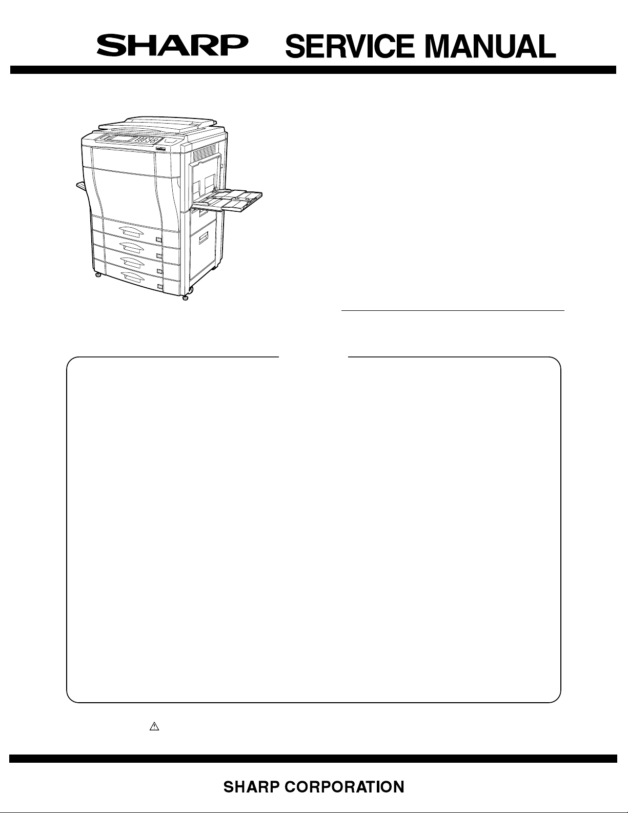
DIGITAL FULL
COLOR COPIER
AR-C150
AR-C250
MODEL
CONTENTS
[ 1 ] CONFIGURATION. . . . . . . . . . . . . . . . . . . . . . . . . . . . . . . . . . . 1-1
[ 2 ] SPECIFICATIONS . . . . . . . . . . . . . . . . . . . . . . . . . . . . . . . . . . . 2-1
[ 3 ] CONSUMABLE PARTS. . . . . . . . . . . . . . . . . . . . . . . . . . . . . . . 3-1
[ 5 ] EXTERNAL VIEW AND INTERNAL STRUCTURE. . . . . . . . . 5-4A
[ 6 ] MACHINE OPERATIONS . . . . . . . . . . . . . . . . . . . . . . . . . . . . . 6-1
[ 7 ] SETTING AND ADJUSTMENTS . . . . . . . . . . . . . . . . . . . . . . . . 7-1
[ 8 ] SIMULATION . . . . . . . . . . . . . . . . . . . . . . . . . . . . . . . . . . . . . . . 8-1
[10] SELF DIAG MESSAGE AND TROUBLESHOOTING . . . . . . 10-2A
[11] MAINTENANCE AND DISASSEMBLY/ASSEMBLY . . . . . . . . 11-1
[12] BLOCK DIAGRAM . . . . . . . . . . . . . . . . . . . . . . . . . . . . . . . . . . 12-1
[13] ACTUAL WIRING CHART . . . . . . . . . . . . . . . . . . . . . . . . . . . . 13-1
AR-C160
[14] OTHERS . . . . . . . . . . . . . . . . . . . . . . . . . . . . . . . . . . . . . . . . 14-8A
This Service Manual describes only the different points from the
AR-C150/C250. For servicing of the AR-C160, therefore, use this
Service Manual together with that of the AR-C150/C250.
Parts marked with “ ” are important for maintaining the safety of the set. Be sure to replace these parts with specified
ones for maintaining the safety and performance of the set.
This document has been published to be used
for after sales service only.
The contents are subject to change without notice.
Page 2

Cautions on laser
Wave length 785 nm
Pulse times
North America: (4.374 µs ±4.4 ns)/7 mm
Europe: (5.732 µs ±5.7 ns)/7 mm
+10 nm
-15 nm
Output power 0.25 - 0.45 mW
Caution
This product contains a low power laser device. To ensure
continued safety do not remove any cover or attempt to
gain access to the inside of the product. Refer all
servicing to qualified personnel.
For North America:
SAFETY PRECAUTIONS
This Digital Copier is rated Class 1 and complies with 21 CFR 1040.10 and 1040.11 of the CDRH standards.
This means that the copier does not produce hazardous laser radiation. For your safety, observe the
precautions below.
●
Do not remove the cabinet, operation panel or any other covers.
●
The copier’s exterior covers contain several safety interlock switches. Do not bypass any safety interlock by
inserting wedges or other items into switch slots.
For Europe:
CLASS 1 LASER PRODUCT
LASER KLASSE 1
LUOKAN 1 LASERLAITE
KLASS 1 LASERAPPARAT
INVISIBLE LASER RADIATION
CAUTION
WHEN OPEN AND INTERLOCKS
DEFEATED. AVOID EXPOSURE
TO BEAM.
VORSICHT
UNSICHTBARE
LASERSTRAHLUNG WENN
ABDECKUNG GEÖFFNET UND
SICHERHEITSVERRIEGELUNG
ÜBERBRÜCKT. NICHT DEM
STRAHL AUSSETZEN.
ADVARSEL
USYNLIG LASERSTRÅLNING VED
ÅBNING, NÅR
SIKKERHEDSBRYDERE ER UDE
AF FUNKTION. UNDGÅ
UDSAETTELSE FOR STRÅLNING.
LAITTEEN KÄYTTÄMINEN
MUULLA KUIN TÄSSÄ
KÄYTTÖOHJEESSA MAINITULLA
TAVALLA SAATTAA ALTISTAA
KÄYTTÄJÄN
TURVALLISUUSLUOKAN 1
YLITTÄVÄLLE NÄKYMÄTTÖMÄLLE
LASERSÄTEILYLLE.
OM APPARATEN ANVÄNDS PÅ
ANNAT SÄTT ÄN I DENNA
BRUKSANVISNING
SPECIFICERATS, KAN
ANVÄNDAREN UTSÄTTAS FÖR
OSYNLIG LASERSTRÅLNING,
SOM ÖVERSKRIDER GRÄNSEN
FÖR LASERKLASS 1.
VAROITUS!
VARNING
INVISIBLE LASER RADIATION WHEN OPEN AND INTERLOCKS DEFEATED.
AVOID EXPOSURE TO BEAM.
CAUTION
UNSICHTBARE LASERSTRAHLUNG WENN ABDECKUNG GEÖFFNET UND
SICHERHEITSVERRIEGELUNG ÜBERERÜCKT. NICHT DEM STRAHL AUSSETZEN.
VORSICHT
USYNLIG LASERSTRÅLING VED ÅBNING, NÅR SIKKERHEDSAFBRYDERE ER
UDE AF FUNKTION. UNDGÅ UDSAETTELSE FOR STRÅLNING.
ADVARSEL
USYNLIG LASERSTRÅLING NÅR DEKSEL ÅPNES OG SIKKERHEDSLÅS BRYTES.
UNNGÅ EKSPONERING FOR STRÅLEN.
ADVERSEL
OSYNLIG LASERSTRÅLNING NÄR DENNA DEL ÄR ÖPPNAD OCH SPÄRRAR ÄR
URKOPPLADE. STRÅLEN ÄR FARLIG. BETRAKTA EJ STRÅLEN.
Laserstrahl
VARNING
AVATTAESSA JA SUOJALUKITUS OHITETTAESSA OLET ALTTIINA NÄKYMÄTÖNTÄ
LASERSÄTEILYLLE. ÄLÄ KATSO SÄTEESEEN.
VAR O!
CLASS 1
LASER PRODUCT
LASER KLASSE 1
(Caution on power source)
Before servicing, be sure to disconnect the power plug from the power outlet.
Page 3
(Relationship between this Service Manual and
previous Service Manuals and how to utilize them)
There are following three kinds of Service Manuals for the AR-C100/
C150/C160/C250.
Document name Document code
AR-C100/C150 00ZARC150/F1E
AR-C100/C150/C250 00ZARC250/F2E
AR-C100/C150/C160/C250 00ZARC160/F1E
The above list is made in the sequence of issuing. The later Service
Manual includes changes occurred before issuing of it.
(Service Manual required for servicing of each model)
Servicing of each model requires the following service manual.
Service Manual required for servicing
MODEL Document name Document code
AR-C100 AR-C100/C150 00ZARC150/F1E
AR-C150 AR-C100/C150 00ZARC150/F1E
AR-C160 AR-C100/C150 00ZARC150/F1E
AR-C100/C150/C250 00ZARC250/F2E
AR-C100/C150/C160/C250 00ZARC160/F1E
AR-C250 AR-C100/C150 00ZARC150/F1E
AR-C100/C150/C250 00ZARC250/F2E
"List of Service Manuals and the contents" below indicates the relationship between each model and the contents of its Service Manual.
Refer to it to utilize the Service Manuals.
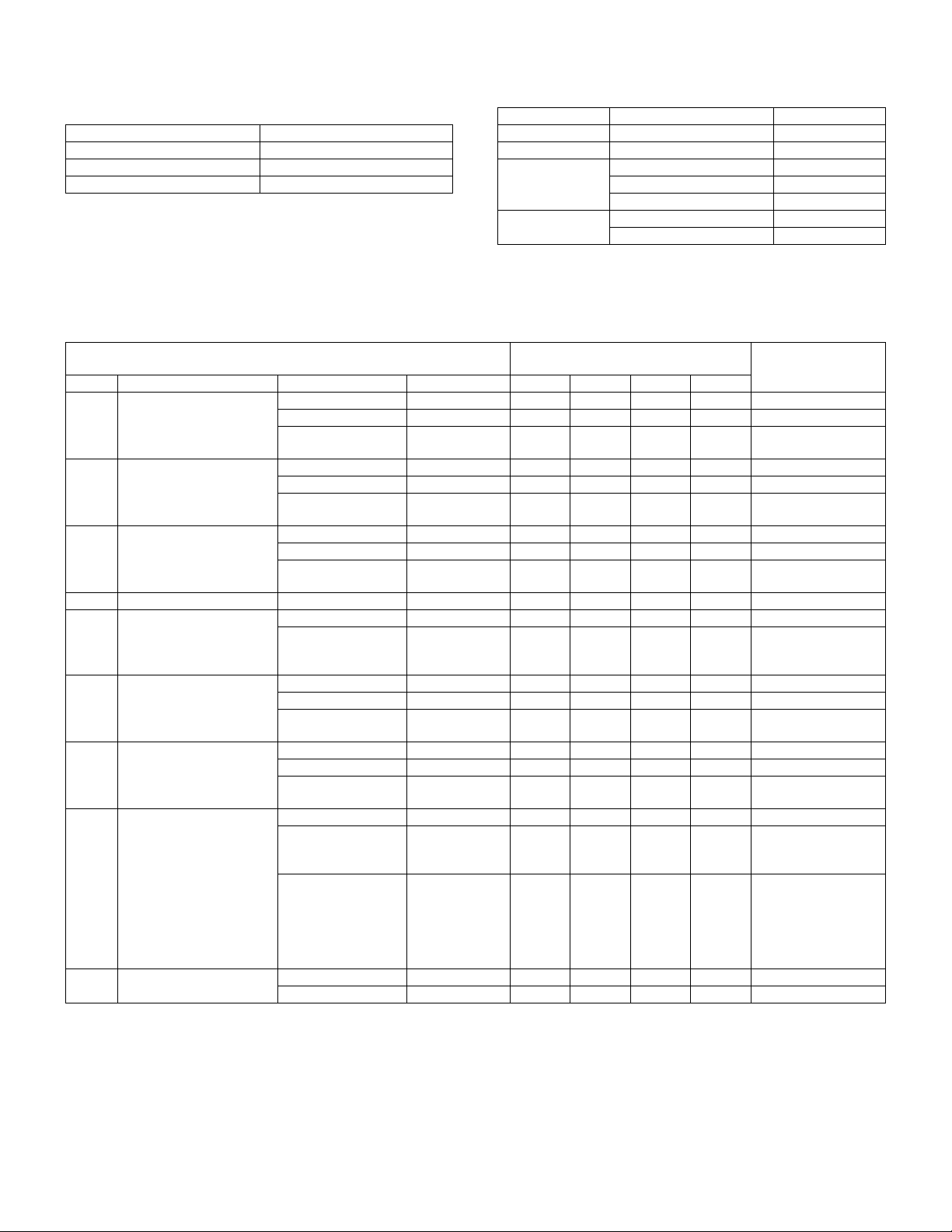
List of Service Manuals and the contents
Documents marked with ❍ includes the latest contents and the different points. Utilize them.
Service Manual
Chapter Contents of Service Manual Document name Document code AR-C100 AR-C150 AR-C160 AR-C250
1 Configuration AR-C100/C150 00ZARC150/F1E
AR-C100/C150/C250 00ZARC250/F2E
AR-C100/C150/C160/
C250
2 Specifications AR-C100/C150 00ZARC150/F1E
AR-C100/C150/C250 00ZARC250/F2E
AR-C100/C150/C160/
C250
3 Consumable parts AR-C100/C150 00ZARC150/F1E
AR-C100/C150/C250 00ZARC250/F2E
AR-C100/C150/C160/
C250
4 Setup AR-C100/C150 00ZARC150/F1E ❍❍❍❍
5 External view and internal
structure
6 Machine operations AR-C100/C150 00ZARC150/F1E
7 Setup and adjustment AR-C100/C150 00ZARC150/F1E
8 Simulation AR-C100/C150 00ZARC150/F1E
9 User program AR-C100/C150 00ZARC150/F1E
AR-C100/C150 00ZARC150/F1E ❍❍❍❍
AR-C100/C150/C160/
C250
AR-C100/C150/C250 00ZARC250/F2E
AR-C100/C150/C160/
C250
AR-C100/C150/C250 00ZARC250/F2E
AR-C100/C150/C160/
C250
AR-C100/C150/C250 00ZARC250/F2E ❍❍❍❍Includes the contents
AR-C100/C150/C160/
C250
AR-C100/C150/C250 00ZARC250/F2E ❍❍❍❍
00ZARC160/F1E ❍❍❍❍Includes the contents
00ZARC160/F1E ❍❍❍❍Includes the contents
00ZARC160/F1E ❍❍❍❍Includes the contents
00ZARC160/F1E ❍ Includes the contents
00ZARC160/F1E ❍❍❍
00ZARC160/F1E ❍❍❍❍Includes the contents
00ZARC160/F1E ❍ Includes only the
Service target model/Service document
reference page
NOTE
of all the models.
of all the models.
of all the models.
of AR-C100/C150/
C250.
of all the models.
of AR-C100/C150/
C250.
differences from the
AR-C100/C150/C250.
(However, the list
includes the contents
of all the models.)
Page 4
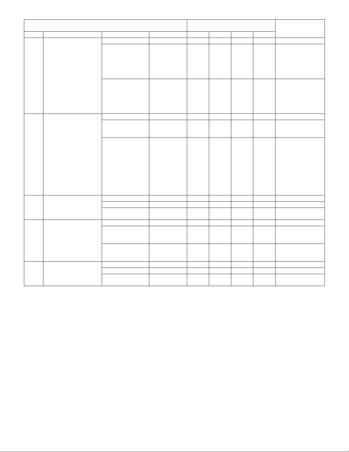
Service Manual
Service target model/Service document
reference page
Chapter Contents of Service Manual Document name Document code AR-C100 AR-C150 AR-C160 AR-C250
10 Self diag message and
troubleshooting
AR-C100/C150 00ZARC150/F1E ❍❍❍❍
AR-C100/C150/C250 00ZARC250/F2E ❍❍❍❍The list includes the
AR-C100/C150/C160/
00ZARC160/F1E ❍ Includes only the
C250
11 Disassembly/assembly and
maintenance
AR-C100/C150 00ZARC150/F1E ❍❍❍❍
AR-C100/C150/C250 00ZARC250/F2E ❍ Include only the
AR-C100/C150/C160/
00ZARC160/F1E ❍❍❍❍Includes only the
C250
12 Block diagram AR-C100/C150 00ZARC150/F1E ❍❍
AR-C100/C150/C250 00ZARC250/F2E ❍
AR-C100/C150/C160/
00ZARC160/F1E ❍
C250
13 Actual wiring diagram AR-C100/C150 00ZARC150/F1E ❍❍ ❍
AR-C100/C150/C250 00ZARC250/F2E ❍ Includes only the
AR-C100/C150/C160/
00ZARC160/F1E ❍ Includes all the
C250
14 Others AR-C100/C150 00ZARC150/F1E
AR-C100/C150/C250 00ZARC250/F2E
AR-C100/C150/C160/
00ZARC160/F1E ❍❍❍❍Includes the contents
C250
NOTE
contents of the ARC100/C150/C250. (The
details are only of the
differences from the
AR-C100/C150/C250.)
differences from the
AR-C100/C150/C250.
(However, the list
includes the contents
of all the models.)
differences from the
AR-C10/C150.
differences from the
AR-C100/C150/C250.
(However, for the
contents of necessary
work items of
maintenance and
servicing of all the
models, refer to this
Manual.)
differences from the
AR-C100/C150/C250.
contents of the ARC160.
of all the models.
Page 5

[ 1 ] CONFIGURATION
1. Main unit and option lineup. . . . . . . . . . . . . . . . . . . . . . . . 1-1
2. Block diagram . . . . . . . . . . . . . . . . . . . . . . . . . . . . . . . . . . 1-3
[ 2 ] SPECIFICATIONS
1. Basic specifications . . . . . . . . . . . . . . . . . . . . . . . . . . . . . 2-1
2. Operating specifications . . . . . . . . . . . . . . . . . . . . . . . . . . 2-1
A. Common operations . . . . . . . . . . . . . . . . . . . . . . . . . . 2-1
B. Copy mode . . . . . . . . . . . . . . . . . . . . . . . . . . . . . . . . . 2-1
3. Engine specifications . . . . . . . . . . . . . . . . . . . . . . . . . . . . 2-8
A. Operation (display/operation) section . . . . . . . . . . . . . 2-8
B. Paper feeding, paper conveyance,
and discharge section . . . . . . . . . . . . . . . . . . . . . . . . . 2-8
C. Scanner section . . . . . . . . . . . . . . . . . . . . . . . . . . . . . 2-9
D. Scanner section . . . . . . . . . . . . . . . . . . . . . . . . . . . . 2-10
E. Image processing section . . . . . . . . . . . . . . . . . . . . . 2-10
F. Fuser section. . . . . . . . . . . . . . . . . . . . . . . . . . . . . . . 2-11
G. Drive section . . . . . . . . . . . . . . . . . . . . . . . . . . . . . . . 2-12
H. Engine controller . . . . . . . . . . . . . . . . . . . . . . . . . . . . 2-12
I. Image processing controller . . . . . . . . . . . . . . . . . . . 2-12
J. Memory . . . . . . . . . . . . . . . . . . . . . . . . . . . . . . . . . . . 2-12
K. Power source . . . . . . . . . . . . . . . . . . . . . . . . . . . . . . 2-12
4. Safety and environmental protection standards . . . . . . . 2-13
A. Safety standards . . . . . . . . . . . . . . . . . . . . . . . . . . . . 2-13
B. Environmental standards. . . . . . . . . . . . . . . . . . . . . . 2-13
5. Ambient conditions . . . . . . . . . . . . . . . . . . . . . . . . . . . . . 2-13
A. Space required . . . . . . . . . . . . . . . . . . . . . . . . . . . . . 2-13
B. Operating ambient conditions . . . . . . . . . . . . . . . . . . 2-13
C. Ambient storage conditions. . . . . . . . . . . . . . . . . . . . 2-13
D. Ambient conditions for transporting. . . . . . . . . . . . . . 2-13
E. Standard temperature and humidity . . . . . . . . . . . . . 2-13
[ 3 ] CONSUMABLE PARTS
1. Consumable parts list . . . . . . . . . . . . . . . . . . . . . . . . . . . . 3-1
2. Compatibility of Supplies for AR-C150/250/160
(Overseas) . . . . . . . . . . . . . . . . . . . . . . . . . . . . . . . . . . . . 3-8
3. Photoconductor, developer, toner. . . . . . . . . . . . . . . . . . . 3-9
A. Serial number identification, effective life . . . . . . . . . . 3-9
4. Paper . . . . . . . . . . . . . . . . . . . . . . . . . . . . . . . . . . . . . . . 3-10
5. Environmental conditions . . . . . . . . . . . . . . . . . . . . . . . . 3-10
[ 5 ] EXTERNAL VIEW AND INTERNAL STRUCTURE
B. Internal parts . . . . . . . . . . . . . . . . . . . . . . . . . . . . . . . 5-4A
[ 6 ] MACHINE OPERATIONS
1. Operation mode . . . . . . . . . . . . . . . . . . . . . . . . . . . . . . . . 6-1
2. Operation menu . . . . . . . . . . . . . . . . . . . . . . . . . . . . . . . . 6-1
3. Pre-heat mode and sleep mode operations . . . . . . . . . . . 6-5
A. Operation timing . . . . . . . . . . . . . . . . . . . . . . . . . . . . . 6-5
B. Pre-heat mode and sleep mode operations . . . . . . . . 6-5
4. Consumable parts life and machine operation . . . . . . . . . 6-8
[ 7 ] SETTING AND ADJUSTMENTS
1. Adjustment/setup items list . . . . . . . . . . . . . . . . . . . . . . . . 7-1
ADJ M1 DV doctor gap adjustment . . . . . . . . . . . . . . . . . 7-2
ADJ M2 DV roller main pole position adjustment . . . . . . 7-2
ADJ M3 Toner concentration control reference level
setting . . . . . . . . . . . . . . . . . . . . . . . . . . . . . . . . 7-3
ADJ M4 High voltage adjustment . . . . . . . . . . . . . . . . . . 7-3
ADJ M5 Paper skew adjustment . . . . . . . . . . . . . . . . . . . 7-5
ADJ M6 Image density sensor adjustment . . . . . . . . . . . 7-5
ADJ M7 Image skew adjustment (Scanner (Writing)
unit) . . . . . . . . . . . . . . . . . . . . . . . . . . . . . . . . . . 7-6
ADJ M8 Photoconductor phase adjustment . . . . . . . . . . 7-8
ADJ M9A Image resist adjustment (Auto adjustment)
(AR-C250/C160) (New version of AR-C150) . . 7-10
CONTENTS
ADJ M9 Main scanning direction copy magnification
ratio adjustment (Manual adjustment)
(Scanner (Writing) unit)
Main scanning direction image registration
adjustment (Manual adjustment)
(Scanner (Writing) unit) . . . . . . . . . . . . . . . . . . 7-12
ADJ M10 Sub scanning direction color image resist
adjustment (Manual adjustment)
(Scanner (Writing) unit) (Color) . . . . . . . . . . . . 7-14
ADJ M11 Image distortion adjustment. . . . . . . . . . . . . . . 7-18
ADJ M12 Image focus (main scanning direction copy
magnification ratio) adjustment (CCD position
adjustment) . . . . . . . . . . . . . . . . . . . . . . . . . . . 7-20
ADJ M13 Sub scanning direction copy magnification ratio
adjustment . . . . . . . . . . . . . . . . . . . . . . . . . . . . 7-21
ADJ M14 Image position adjustment (Main scanning
direction) (Print engine) . . . . . . . . . . . . . . . . . . 7-21
ADJ M15 Image position adjustment (Main scanning
direction) (Scanner (Writing)). . . . . . . . . . . . . . 7-22
ADJ M16 "Image position, image loss, void area
adjustment" . . . . . . . . . . . . . . . . . . . . . . . . . . . 7-22
ADJ M17 Copy color balance and density adjustment . . 7-24
ADJ M18 Document size sensor adjustment. . . . . . . . . . 7-38
ADJ M19 Waste toner full detection level adjustment . . . 7-38
ADJ M20 Touch panel coordinates setting . . . . . . . . . . . 7-38
ADJ M21 Transfer belt level adjustment
(Transfer belt traveling adjustment). . . . . . . . . 7-39
ADJ M22 Fusing pressure adjustment . . . . . . . . . . . . . . 7-39
ADJ M23 Power voltage adjustment
(AR-C100/C150/C250) . . . . . . . . . . . . . . . . . . 7-40
ADJ M24 Manual paper feed size detection level
adjustment . . . . . . . . . . . . . . . . . . . . . . . . . . . . 7-40
ADJ M25 OHP sensor adjustment. . . . . . . . . . . . . . . . . . 7-40
[ 8 ] SIMULATION
1. Outline and purpose . . . . . . . . . . . . . . . . . . . . . . . . . . . . . 8-1
2. Code system simulation . . . . . . . . . . . . . . . . . . . . . . . . . . 8-1
A. Operating procedures and operations. . . . . . . . . . . . . 8-1
B. Simulation list . . . . . . . . . . . . . . . . . . . . . . . . . . . . . . . 8-3
C. Details of simulation . . . . . . . . . . . . . . . . . . . . . . . . . 8-11
[10] SELF DIAG MESSAGE AND TROUBLESHOOTING
5. List . . . . . . . . . . . . . . . . . . . . . . . . . . . . . . . . . . . . . . . . 10-2A
6. Details. . . . . . . . . . . . . . . . . . . . . . . . . . . . . . . . . . . . . . 10-6A
[11] MAINTENANCE AND DISASSEMBLY/ASSEMBLY
1. Necessary procedure for maintenance and servicing. . . 11-1
2. List . . . . . . . . . . . . . . . . . . . . . . . . . . . . . . . . . . . . . . . . . 11-4
3. Details. . . . . . . . . . . . . . . . . . . . . . . . . . . . . . . . . . . . . . . 11-9
S06 Image process section. . . . . . . . . . . . . . . . . . . 11-9
S07 Fusing/paper exit section. . . . . . . . . . . . . . . . . 11-9
S10 PWB . . . . . . . . . . . . . . . . . . . . . . . . . . . . . . . 11-16
[12] BLOCK DIAGRAM
1. Overall block diagram. . . . . . . . . . . . . . . . . . . . . . . . . . . 12-1
[13] ACTUAL WIRING CHART . . . . . . . . . . . . . . . . . . . . . . . . . 13-1
[14] OTHERS
1. List of adjustment/setup values . . . . . . . . . . . . . . . . . . 14-8A
Page 6
[1] CONFIGURATION
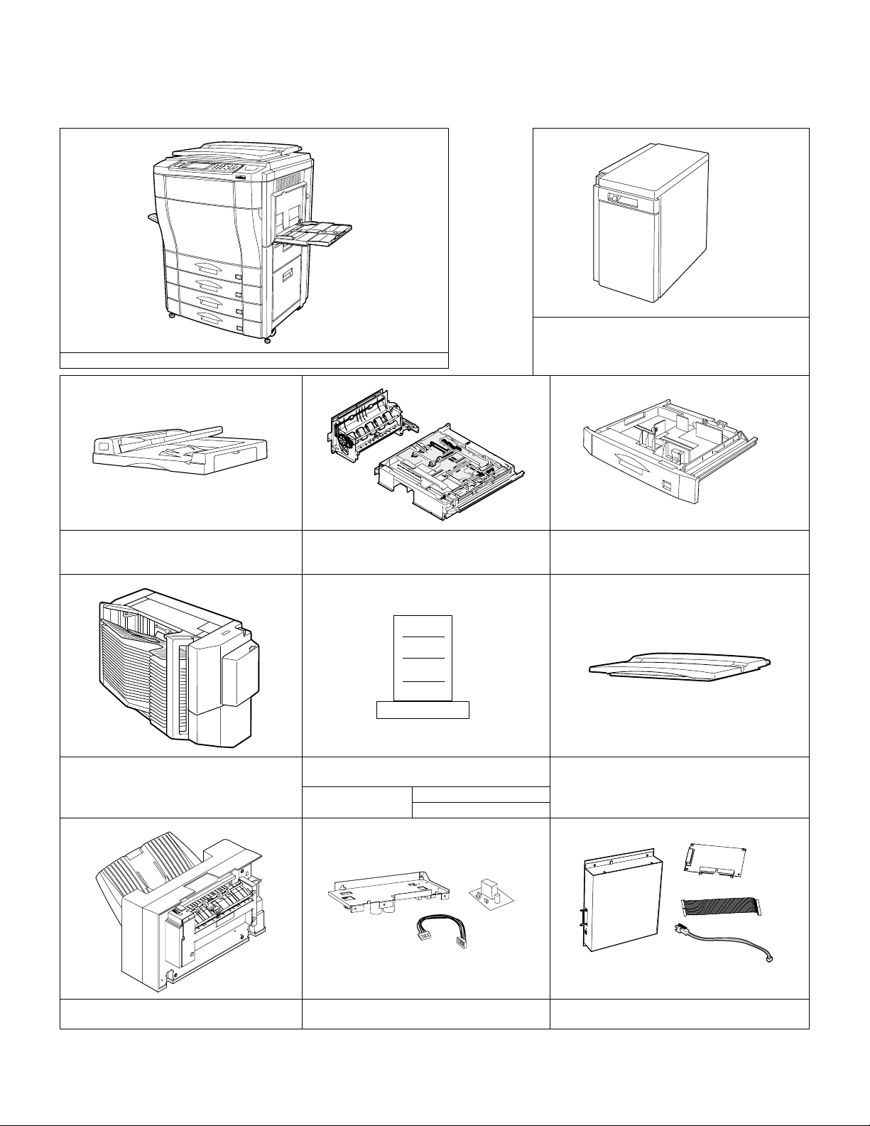
1. Main unit and option lineup
(1) Main unit lineup (2) Option lineup
AR-LC2 (AR-C150/C250)/Large capacity tray
(excluding Japan)
AR-C150/C250/C160
AR-LC2N (AR-C160/C250/C150)/ Large capacity tray
(excluding Japan)
AR-RF1/Reversing automatic document feeder
AR-SS2/20 bin staple sorter
AR-DU2 (AR-C150/C250)/Duplex module
AR-DU2N (AR-C160/C250/C150)/Duplex
module
AR-PE1 (AR-C150/C250) / Fiery Printer
Printer engine I/F kit
(AR-C150/C250)
controller
(AR-PX1)
(AR-PX2) (North America)
AR-CS2 (AR-C150/C250)/500 sheet paper drawer
AR-CS2N (AR-C160/C250/C150)/500 sheet paper
drawer
AR-VR2/Original cover (excluding Japan)
AR-FN4 Finisher (Use for AR-C250/C160) AR-PX3/PX4 (AR-C160)/Printer power unit
1 – 1
CD ROM
Operation Manual
AR-PE2 (AR-C160)/Built-in type printer controller
(with I/F PWB)
Page 7
(3) Option combinations
Option
Item Model
Large capacity tray
Reversing automatic document feeder AR-RF1 AR-C150/C250/C160 Supplied from the copier body.
Duplex module
500 sheet paper drawer
20 bin staple sorter AR-SS2 AR-C150/C250/C160 Supplied from the copier body.
Department supervision card reader (Japan only) AR-EC1 AR-C150/C250/C160 Supplied from the copier body. Japan only
Fiery Printer controller/Printer engine I/F kit
Fiery printer controller (built-in type, with printer
connection kit)/DC power unit
Original cover AR-VR2 AR-C150/C250/C160 Outside of Japan only
Finisher AR-FN4 AR-C250/C160 Supplied from the copier body
Item Model Finisher
RADF AR-RF1 ❍❍ ❍ ❍❍❍❍—
Duplex module
Paper feed tray
LCC (Outside of Japan only)
20 bin staple sorter AR-SS2 ✕❍ ❍ — — — — —
Department supervision card reader (Japan only) AR-EC1 ❍▲ — — — — — —
Fiery Printer controller/Printer I/F kit
Fiery printer controller (built-in type, with printer
connection kit)/DC power unit
Finisher AR-FN4 — — — — — — — —
❍: Possible ✕: Not possible ▲: Possible; however, only operational in copy mode (does not operation in printer mode)
AR-LC2 AR-C150/C250 Supplied from the copier body. Outside of Japan only
AR-LC2N AR-C150/C250/C160 Supplied from the copier body. Outside of Japan only
AR-DU2 AR-C150/C250 Supplied from the copier body.
AR-DU2N AR-C150/C250/C160 Supplied from the copier body.
AR-CS2 AR-C150/C250 Supplied from the copier body.
AR-CS2N AR-C150/C250/C160 Supplied from the copier body.
AR-PE1/
AR-PX1/
AR-PX2
AR-PE2/
AR-PX3/
AR-PX4
AR-DU2 ❍❍ ❍ ❍❍✕— —
AR-DU2N ❍❍ ❍ ❍❍✕— —
AR-CS2 ❍❍ ❍ ❍❍— — —
AR-CS2N ❍❍ ❍ ❍❍— — —
AR-LC2 ❍❍ ❍ ❍— — — —
AR-LC2N ❍❍ ❍ ❍— — — —
AR-PE1/
AR-PX1/
AR-PX2
AR-PE2/
AR-PX3/
AR-PX4
Model Power source Note
AR-C150/C250
AR-C160
Fiery
Printer
controller
❍ — — — — — — —
❍ — — — — — — —
Supplied from the copier body.
(AR-PX1)
Supplied from the exclusive
DC power unit.
Department
supervision
card reader
(Japan only)
20 bin
staple
sorter
LCC
(Outside
of Japan
only)
Sorting is disabled in the
copy mode.
500
sheet
paper
drawer
Duplex
module
RADF
1 – 2
Page 8
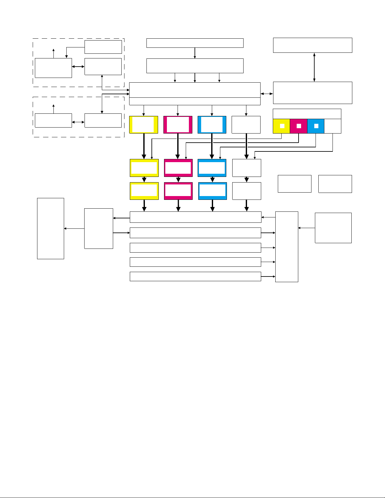
2. Block diagram
Network
Built-in type
printer controller
(option)
AR-C160
Network
Printer controller
(option)
AR-C150/C250
Finisher/
Sorter unit
(Option)
DC power unit
(option)
Printer I/F PWB
(option)
Printer I/F PWB
(option)
Fusing/
paper exit
section
RADF unit (Option)
Image scanning (reading) section
Image forming section
(SCAN ICU PWB / IMAGE ICU PWB / MAIN ICU PWB)
Page memory
Scanner
(writing)
section (Y)
OPC section
(Y)
Developing
section (Y)
Scanner
(writing)
section (M)
OPC section
(M)
Developing
section (M)
Scanner
(writing)
section (C)
OPC section
(C)
Developing
section (C)
Scanner
(writing)
section (K)
OPC section
(K)
Developing
section (K)
Transfer section
Duplex section (Option) / Paper feed tray section 4 (Option)
Paper feed tray section 1
Paper feed tray section 2
Operation section
Engine control section
(MAIN PCU PWB / SUB PCU PWB)
Toner hopper section
MKCY
DC power unit
AC power unit
Large capacity
paper feed tray
(Option)
Paper
transport
section
Paper feed tray section 3
1 – 3
Page 9
[2] SPECIFICATIONS
1. Basic specifications
(1) Type
Type Console
Operation mode Format
Copy mode Full-color digital (electronic photographic)
(2) Target users
Mode Volume of usage
Copy mode Scope 5,000 to 20,000 sheets/month
Average copy volume 8,000 to 12,000 sheets/month
(3) External dimensions
AR-C150/C250/C160 AR-C100
Packaged — —
Main unit 750 × 695 × 1010mm
(29.5 × 27.4 × 39.8)
(height: floor to glass
surface)
750 × 695 × 1060mm
(29.5 × 27.4 × 41.7)
(height: floor to OC top
surface)
725 × 695 × 1010mm
(28.5 × 27.4 × 39.8)
(height: floor to glass
surface)
725 × 695 × 1060mm
(28.5 × 27.4 × 41.7)
(height: floor to OC top
surface)
(4) Weight
AR-C150/C250/C160 AR-C100
Packaged About 164.6Kg (363 lbs) About 167.6Kg (370 lbs)
Main unit 152Kg (335 lbs) 155Kg (342 lbs)
(5) Machine life
Total (copy and print) volume 800,000 sheets
Lifetime 5 years
2. Operating specifications
A. Common operations
(1) Warm-up time/Jam recovery time
a. Warm-up time (ambient temp. of 20°C)
After turned on AR-C100/C150 Max. 200 seconds
AR-C250/C160 Max. 330 seconds
Recovery from warm-up
mode
b. Jam recovery time
Jam recovery time Under 30 seconds (conditions: door open/fusing
AR-C100 130 seconds
AR-C150/C250/C160 30 seconds
unit drawn)
Under 8 seconds (conditions: door open)
B. Copy mode
(1) Document size
Scan mode Paper type Location
Original
stand mode
RADF mode AB Series Japan A5 A3 A3, B4, A4, A4R, B5, B5R, A5
AB Series Japan B5 A3 A3, B4, A4, A4R, B5, B5R
Australia A5 A3, A4, A4R, A5, 216 × 330mm
Other A A3, B4, A4, A4R, A5
Other B B5 A3, B4, A4, A4R, B5, B5R
Inch Series 8.5 × 5.5 11 × 17 11 × 17, 8.5 × 14, 8.5 × 11, 8.5 × 11R, 8.5 × 5.5
Australia A3, A4, A4R, A5, 216 × 330mm, B4
Other A A3, B4, A4, A4R, A5
Other B A3, B4, A4, A4R, B5, B5R, A5
Inch Series 8.5 × 5.5 11 × 17 11 × 17, 8.5 × 14, 8.5 × 11, 8.5 × 11R, 8.5 × 5.5
(2) Paper size
Paper type
AB Series
Inch Series
Dimensions Paper size
Min. Max. Min. Max.
——
——
A6 (A6R) Postcard A3 wide (305 × 457 mm) A3 wide (305 × 457 mm)
Dimensions Paper size
Min. Max. Min. Max.
A3, B4, A4, A4R, B5, B5R, A5
8.5 × 5.5 12 × 18 12 × 18, 11 × 17, 8.5 × 14, 8.5 × 11,
8.5 × 11R, 8.5 × 5.5
Paper sizes Note
Paper sizes Note
2 – 1
Page 10
(3) Exposure
a. Exposure mode
(AR-C100/C150)
Copy mode Model
Color Text/Photo mode Manual AR-C100/C150 Area separation, filter
Auto Color blance, density fixed
Text mode Manual AR-C150
Auto Color blance, density fixed
Printed Photo mode Manual AR-C150 Filter process, dither pattern
Photo mode Manual AR-C100/C150
Map mode Manual AR-C150
Monochrome Text/Photo mode Manual AR-C150 Area separation, filter
(AR-C250)
Color Copy
document
mode
Normal mode Text mode Manual AR-C250 Area separation, filter
Monochrome Copy
document
mode
Normal mode Text mode Manual AR-C250 Area separation, filter
Auto (Non pre-
scan mode)
Auto (Pre-scan
mode)
Text mode Manual AR-C150
Auto (Non pre-
scan mode)
Auto (Pre-scan
mode)
Printed Photo mode Manual AR-C150 Filter process, dither pattern
Photo mode Manual AR-C100/C150
Map mode Manual AR-C100/C150
Copy mode Model
Text/Printed Photo
mode
Printed Photo mode Manual AR-C250 Filter process, dither pattern Pre-scan operation allowed
Text mode Manual AR-C250 Area separation, filter
Text/Printed Photo
mode
Printed Photo mode Manual AR-C250 Filter process, dither pattern
Photo mode Manual AR-C250
Text/Photo mode Manual AR-C250 Area separation, filter
Map mode Manual AR-C250 Filter process, dither pattern
Text/Printed Photo
mode
Printed Photo mode Manual AR-C250 Filter process, dither pattern
Text mode Manual AR-C250 Area separation, filter
Text/Printed Photo
mode
Printed Photo mode Manual AR-C250 Filter process, dither pattern
Photo mode Manual AR-C250
Text/Photo mode Manual AR-C250 Area separation, filter
Map mode Manual AR-C250 Filter process, dither pattern
Manual AR-C250 Area separation, filter
Auto Color balance, density fixed.
Manual AR-C250
Auto Color balance, density fixed.
Auto Color balance, density fixed.
Manual AR-C250 Area separation, filter
Auto (Non pre-
scan mode)
Auto (Pre-scan
mode)
Manual AR-C250
Auto (Non pre-
scan mode)
Auto (Pre-scan
mode)
Auto (Non pre-
scan mode)
Auto (Pre-scan
mode)
AR-C150 Pre-scan can be inhibited
AR-C150
AR-C150 Pre-scan can be inhibited
AR-C150
AR-C250 Pre-scan oepration can be
AR-C250
AR-C250 Pre-scan oepration can be
AR-C250
AR-C250 Pre-scan oepration can be
AR-C250
Image process,
gradation control
process, dither pattern
process, dither pattern
Image process,
gradation control
process, dither pattern
process, dither pattern
process, dither pattern
process, dither pattern
process, dither pattern
process, dither pattern
process, dither pattern
process, dither pattern
Note
with the user program.
with the user program.
Note
Pre-scan operation allowed
Pre-scan operation allowed
inhibited with the user
program.
inhibited with the user
program.
inhibited with the user
program.
2 – 2
Page 11
(AR-C160)
Color Copy
document
mode
Normal mode Text mode Manual AR-C160 Area separation, filter
Color
enhancement
mode
Monochrome Copy
document
mode
Normal mode Text mode Manual AR-C160 Area separation, filter
Copy mode Model
Text/Printed Photo
mode
Printed Photo mode Manual AR-C160 Filter process, dither pattern Pre-scan operation allowed
Text mode Manual AR-C160 Area separation, filter
Text/Printed Photo
mode
Printed Photo mode Manual AR-C160 Filter process, dither pattern
Photo mode Manual AR-C160
Text/Photo mode Manual AR-C160 Area separation, filter
Map mode Manual AR-C160 Filter process, dither pattern
Text mode Manual AR-C160 Area separation, filter
Text/Printed Photo
mode
Printed Photo mode Manual AR-C160 Filter process, dither pattern Pre-scan operation allowed
Photo mode Manual AR-C160 Pre-scan operation allowed
Text/Photo mode Manual AR-C160 Area separation, filter
Map mode Manual AR-C160 Filter process, dither pattern Pre-scan operation allowed
Text/Printed Photo
mode
Printed Photo mode Manual AR-C160 Filter process, dither pattern
Text mode Manual AR-C160 Area separation, filter
Text/Printed Photo
mode
Printed Photo mode Manual AR-C160 Filter process, dither pattern
Photo mode Manual AR-C160
Text/Photo mode Manual AR-C160 Area separation, filter
Map mode Manual AR-C160 Filter process, dither pattern
Manual AR-C160 Area separation, filter
Auto Color balance, density fixed.
Manual AR-C160
Auto Color balance, density fixed.
Auto Color balance, density fixed.
Auto Pre-scan operation allowed
Manual AR-C160 Pre-scan operation allowed
Auto Pre-scan operation allowed
Auto Pre-scan operation allowed
Manual AR-C160 Area separation, filter
Auto (Non pre-
scan mode)
Auto (Pre-scan
mode)
Manual AR-C160
Auto (Non pre-
scan mode)
Auto (Pre-scan
mode)
Auto (Non pre-
scan mode)
Auto (Pre-scan
mode)
AR-C160 Pre-scan oepration can be
AR-C160
AR-C160 Pre-scan oepration can be
AR-C160
AR-C160 Pre-scan oepration can be
AR-C160
Image process,
gradation control
process, dither pattern
process, dither pattern
process, dither pattern
process, dither pattern
process, dither pattern
process, dither pattern
process, dither pattern
process, dither pattern
process, dither pattern
process, dither pattern
Note
Pre-scan operation allowed
Pre-scan operation allowed
Pre-scan operation allowed
Pre-scan operation allowed
inhibited with the user
program.
inhibited with the user
program.
inhibited with the user
program.
2 – 3
Page 12
Models and copy mode
Models and the copy mode are shown below. The copy mode differs depending on the model.
The copy mode (Note *1) is substantially same as the copy mode (Note *2), and they differ in display.
Since the descriptions on the copy mode of the AR-C250/C160 is the most accurate, refer to it.
Copy mode
Color Copy
document
mode
Normal mode Manual TEXT MODE TEXT MODE TEXT MODE — Area separation, filter
Color
enhancement
mode
Monochrome Copy
document
mode
Normal mode Manual TEXT MODE TEXT MODE TEXT MODE — Area separation, filter
Manual TEXT/
Manual PRINTED
Manual TEXT MODE TEXT MODE — — Area separation, filter
Auto Color balance, density
Manual TEXT/
Auto Color balance, density
Manual PRINTED
Manual PHOTO MODE PHOTO MODE PHOTO MODE PHOTO MODE
Manual TEXT/PHOTO
Auto Color balance, density
Manual MAP MODE MAP MODE MAP MODE — Filter process, dither
Manual — TEXT MODE — — Area separation, filter
Auto Pre-scan operation allowed
Manual — TEXT/
Auto Pre-scan operation allowed
Manual — PRINTED
Manual — PHOTO MODE — — Pre-scan operation allowed
Manual — TEXT/PHOTO
Auto Pre-scan operation allowed
Manual — MAP MODE — — Filter process, dither
Manual TEXT/
Manual PRINTED
Manual TEXT MODE TEXT MODE — — Area separation, filter
Auto (Non prescan mode)
Auto (Pre-scan
mode)
Manual TEXT/
Auto (Non pre-
scan mode)
Auto (Pre-scan
mode)
Manual PRINTED
Manual PHOTO MODE PHOTO MODE PHOTO MODE PHOTO MODE
Manual TEXT/PHOTO
Auto (Non pre-
scan mode)
Auto (Pre-scan
mode)
Manual MAP MODE MAP MODE MAP MODE MAP MODE Filter process, dither
AR-C250 AR-C160 AR-C150 AR-C100
PRINTED
PHOTO MODE
PHOTO MODE
PRINTED
PHOTO MODE
(*1)
PHOTO MODE
MODE
PRINTED
PHOTO MODE
PHOTO MODE
PRINTED
PHOTO MODE
(*1)
PHOTO MODE
MODE
TEXT/
PRINTED
PHOTO MODE
PRINTED
PHOTO MODE
TEXT/
PRINTED
PHOTO MODE
(*1)
PRINTED
PHOTO MODE
TEXT/PHOTO
MODE
PRINTED
PHOTO MODE
(*1)
PHOTO MODE
MODE
TEXT/
PRINTED
PHOTO MODE
PRINTED
PHOTO MODE
TEXT/
PRINTED
PHOTO MODE
(*1)
PRINTED
PHOTO MODE
TEXT/PHOTO
MODE
— — Area separation, filter
— — Filter process, dither
TEXT/PHOTO
MODE (*2)
PRINTED
PHOTO MODE
— — Area separation, filter
— — Pre-scan operation allowed
— — Filter process, dither
— — Area separation, filter
— — Area separation, filter
— — Filter process, dither
TEXT/PHOTO
MODE (*2)
PRINTED
PHOTO MODE
— — Area separation, filter
TEXT/PHOTO
MODE (*2)
— Filter process, dither
—
— Filter process, dither
Image process,
gradation control
process, dither pattern
pattern
process, dither pattern
process, dither pattern
pattern
process, dither pattern
pattern
process, dither pattern
pattern
process, dither pattern
pattern
process, dither pattern
pattern
process, dither pattern
process, dither pattern
pattern
process, dither pattern
pattern
NOTE
Pre-scan operation allowed
Pre-scan operation allowed
Pre-scan operation allowed
fixed.
fixed.
fixed.
Pre-scan operation allowed
Pre-scan operation allowed
Pre-scan operation allowed
Pre-scan operation allowed
Pre-scan oepration can be
inhibited with the user
program.
Pre-scan oepration can be
inhibited with the user
program.
Pre-scan oepration can be
inhibited with the user
program.
2 – 4
Page 13
b. Relationship between pre-scan operations and the copy mode
Color Copy B/W Copy
Copy mode
COPY OF COPY mode ONCOPY OF COPY
mode OFF
AUTO TEXT/
PRTD.PHOTONO(Switch to Manual mode)
TEXT/PHOTO NO
TEXT NO
MANUAL TEXT/
PRTD.PHOTO
TEXT/PHOTO
PRINTED
PHOTO
PHOTO
(Switch to Manual mode)
(Switch to Manual mode)
YES YES YES YES YES
NO
Key is not displayed
YES YES YES YES YES
NO
Key is not displayed
YES YES
YES YES
YES YES
YES
[COPY OF COPY]
key is not displayed
YES
[COPY OF COPY]
key is not displayed
TEXT YES YES YES YES YES
MAP
NO
Key is not displayed
YES
[COPY OF COPY]
key is not displayed
c. Resolution
• Read
Main scanning direction Sub scanning direction
Basic resolution Basic resolution
600dpi 600dpi
•Write
Main scanning direction Sub scanning direction
Basic resolution Basic resolution
600dpi 600dpi
d. Gradation/image processing
Scanning Printing
256 gradations (8bit) 256 gradations (8bit)
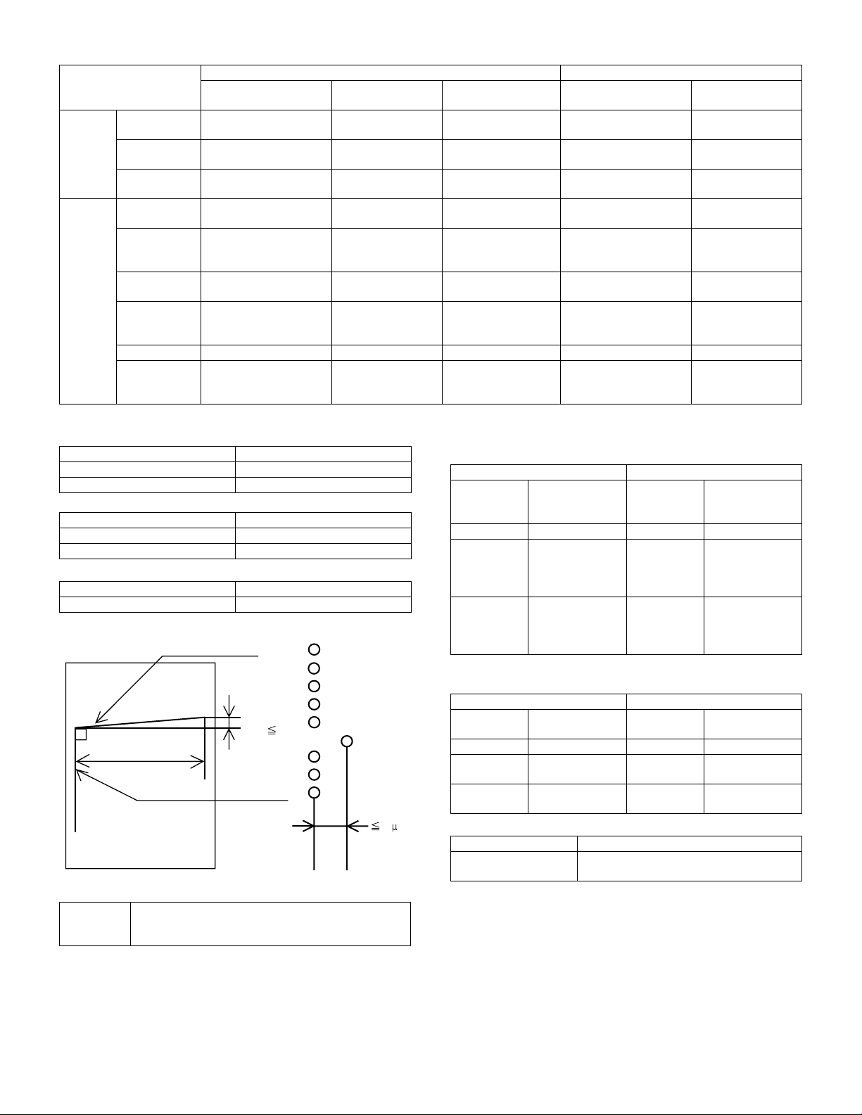
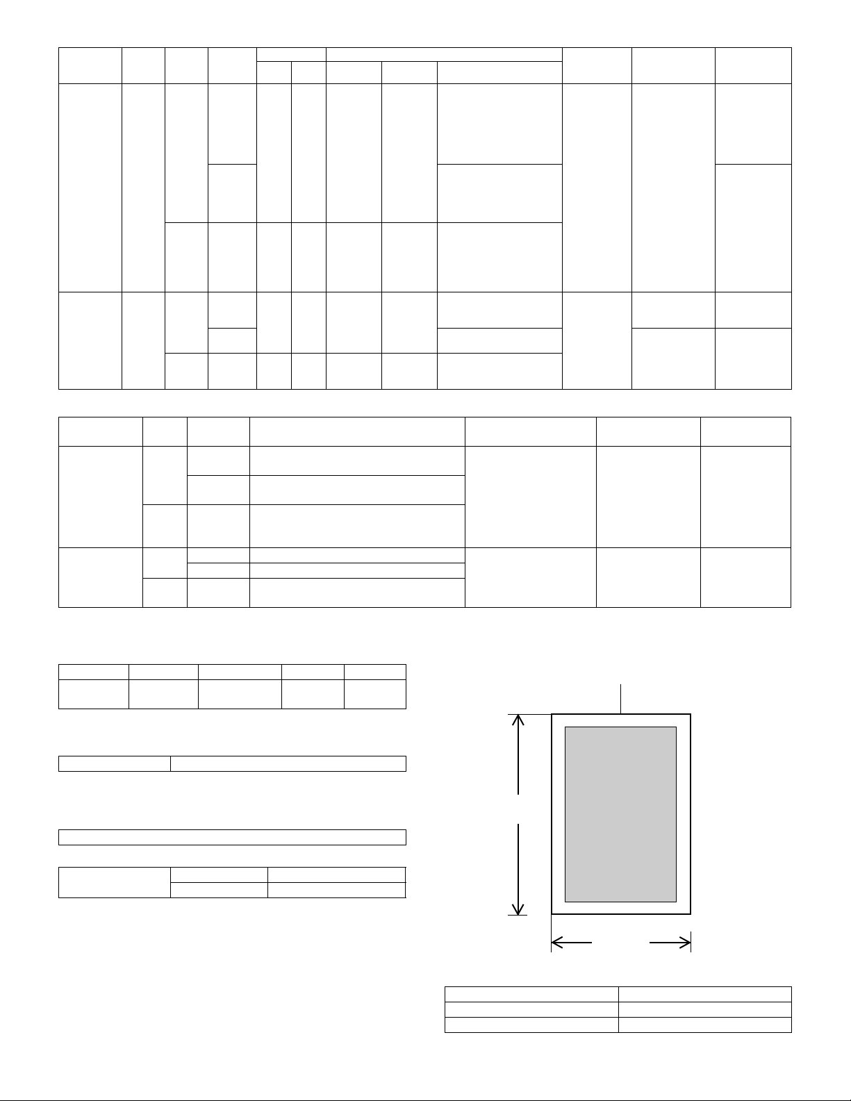
e. Distortion
Print horizontal line
D
1m
| D |
203mm
Print
vertical line
60 m
f. Toner save mode
Toner save
percentage
Approx 15%
∗
Can only be set for monochrome mode
(set by key operator) (Set by simulation in Japan and the U.K.)
Color enhancement
mode (AR-C160 only)
YES
YES
YES
COPY OF COPY mode ONCOPY OF COPY
mode OFF
NO
(Switch to Manual mode)
NO
(Switch to Manual mode)
NO
(Switch to Manual mode)
NO
Key is not displayed
NO
Key is not displayed
NO
Key is not displayed
YES
YES
YES
YES
[COPY OF COPY]
key is not displayed
YES
[COPY OF COPY]
key is not displayed
YES
[COPY OF COPY]
key is not displayed
(4) Copy magnification
a. Copy magnification (independent magnification by direction is
possible)
Main scanning direction Sub scanning direction
Magnification
Mode
range/fixed
Mode
magnification
Zoom mode 25/50 to 400%
Fixed
magnification
mode
25, 50, 70, 81, 86,
100, 115, 122,
141, 200, 400%
(AB Series)
Fixed
magnification
mode
25, 50, 64, 77, 95,
100, 121, 129,
141, 200, 400%
(Inch Series)
∗
The minimum copy magnification for the AR-C100 is 50%.
∗ Zoom mode 25/50 to 400%
Fixed
magnification
mode
(AB Series)
Fixed
magnification
mode
(Inch Series)
b. Copy magnification precision
Main scanning direction Sub scanning direction
Copy
magnification
Magnification
precision
Copy
magnification
Normal copy 100% ± 0.8% Normal copy 100% ± 0.8%
Enlargement
copy
Reduction
copy
Set magnification
± 1.0%
Set magnification
± 1.0%
Enlargement
copy
Reduction
copy
c. Zoom method
Main scanning direction Performed through image processing
Sub scanning direction Performed by changing image processing
and scanning speed
Magnification
range/fixed
magnification
25, 50, 70, 81, 86,
100, 115, 122,
141, 200, 400%
25, 50, 64, 77, 95,
100, 121, 129,
141, 200, 400%
Magnification
precision
Set magnification
± 1.0%
Set magnification
± 1.0%
2 – 5
Page 14
(5) Job speed
Copy method for each copy mode
Black-and-white copy Color copy
Up to A4/LT B4/RG to A3/WLT Up to A4/LT B4/RG to A3/WLT
Single-side
copy
Duplex
copy
1 scan/
multi-copy
1 scan/
multi-copy
1 scan/multi-copy
Multi scan/copy * (AR-C150/
C160)
1 scan/multi copy (AR-C250)
Multi scan/copy
(AR-C150/C160)
1 scan/multi copy (AR-C250)
Multi scan/copy *
(AR-C150/C160)
1 scan/multi copy (AR-C250)
Multi scan/copy
(AR-C150/C160)
1 scan/multi copy (AR-C250)
Multi scan/copy * —
* No multi-copy mode, only single copy
a. First copy time
• Original stand mode (non SPF/ADF/RADF mode) (Unit: sec.)
Paper supply mode Paper size
AR-C150 AR-C160 AR-C250 AR-C150 AR-C160/C250
Color Monochrome
Manual paper feed 8.5 × 11, A4 (Normal paper) 9.8 19.5
A4, 11 × 8.5 (OHP) 84.8 94.5
B5, A4, 11 × 8.5 (thick paper) 69.8 — 79.5
B5, A4, 11 × 8.5 (thick paper) (Mode 1) (106 – 130g/m
B5, A4, 11 × 8.5 (thick paper) (Mode 2) (131 – 200g/m
(131 – 280g/m
2
: AR-C160)
2
) — 69.8 — 79.5
2
)
— 119.8 — 129.5
1st paper feed tray A4 10.5 9.8 10.2 19.5
8.5 × 11 10.5 9.8 10.2 19.5
2nd paper feed tray A4 11.3 10.4 11.1 20.3
8.5 × 11 11.3 10.4 11.1 20.3
3rd paper feed tray A4 12.2 11.0 12.0 21.2
8.5 × 11 12.2 11.0 12.0 21.2
4th paper feed tray A4 13.1 11.6 12.9 22.1
8.5 × 11 13.1 11.6 12.9 22.1
LCC A4 10.2 9.8 10.2 19.5
8.5 × 11 10.2 9.8 10.2 19.5
∗
1st paper feed tray is installed for optional slot.
b. Multi-copy speed
(Conditions) Scanner speed: 15 cpm, using A4/letter standard paper, and no prescan
(Conditions) S
→ S color: One copy of A4 (L1) original (10 sheets), no optional settings other than RADF, and not including fast copy
(AR-C150)
Color Monochrome
1 scan: 1 copy 1 scan: Multiple copy
Copy mode Paper size
Original
stand
mode
S
→ S
(1 – 3
paper
feed
tray)
A3 7 7 6 13 13 13
A3 wide (12 × 18) (
B4 9 9 8 15 15 15
A4 15 15 12 25 (24) 25 (24) 25 (24)
A4R 111110191919
Reduction
copy (25%)
∗1) 776777
Copy magnification Copy magnification
Normal copy
(100%)
Enlargement
copy (400%)
Reduction
copy (25%)
Normal copy
A5 15 15 12 25 25 25
B5 15 15 12 25 25 25
B5R 111110191919
11 × 17 7 7 6 13 13 13
8.5 × 14 9 9 8 15 15 15
8.5 × 11 15 15 12 25 25 25
8.5 × 11R 11 11 10 19 19 19
8.5 × 5.5 15 15 12 25 (24) 25 (24) 25 (24)
8.5 × 13/F.S 9 9 8 15 15 15
A4, 11 × 8.5 (OHP) 101010101010
B5, A4, 11 × 8.5 (thick paper) 10 10 10 10 10 10
Other than B5, A4, 11 × 8.5
555555
(thick paper)
The numbers in the parenthesis are the copy speeds when the 4th paper cassette is used.
A3 wide copy
1 scan/multi copy
(B&W) (AR-C250)
Multi scan/copy
(color) (AR-C250)
Multi scan/copy
(color/B&W) (AR-C150/C160)
Enlargement
(100%)
copy (400%)
2 – 6
Page 15
(AR-C250)
Color Monochrome
1 scan: Multiple copy (1 scan: 1 copy) 1 scan: Multiple copy
Copy mode Paper size
Original
stand
mode
S
→
(1 – 3
paper
feed
tray)
S
A3 13 13 13 13 13 13
A3 wide (12 × 18) (
B4 15 15 15 15 15 15
A4 25 (24) 25 (24) 25 (24) 25 (24) 25 (24) 25 (24)
A4R 191919191919
A5 25 (
B5 25 (
Reduction
copy (25%)
∗1) 777777
Copy magnification Copy magnification
Normal copy
(100%)
26) 25 (∗26) 25 (∗26) 25 (∗26) 25 (∗26) 25 (∗26)
∗
26) 25 (∗26) 25 (∗26) 25 (∗26) 25 (∗26) 25 (∗26)
∗
Enlargement
copy (400%)
Reduction
copy (25%)
Normal copy
(100%)
Enlargement
copy (400%)
B5R 191919191919
11 × 17 13 13 13 13 13 13
8.5 × 14 15 15 15 15 15 15
8.5 × 11 25 (24) 25 (24) 25 (24) 25 (24) 25 (24) 25 (24)
8.5 × 11R 19 19 19 19 19 19
26) 25 (∗26) 25 (∗26) 25 (∗26) 25 (∗26) 25 (∗26)
8.5 × 5.5 25 (
∗
8.5 × 13/F.S 15 15 15 15 15 15
A4, 11 × 8.5 (OHP) 10 10 10 10 10 10
B5, A4, 11 × 8.5 (thick paper) 10 10 10 10 10 10
Other than B5, A4, 11 × 8.5
555555
(thick paper)
The numbers in the parenthesis are the copy speeds when the 4th paper cassette is used.
(
1): 1 scan: 1 copy
∗
: Only for Taiwan version
∗
(AR-C160)
Color Monochrome
1 scan:1 copy 1 scan:Multiple copy
Copy mode Paper size
Original
stand
mode
S
→ S
(1 – 3
paper
feed
tray)
A3 7 7 6 15 15 15
A3 wide (12 × 18) (
B4 9 9 8 17 17 17
A4 16 16 12 32 (31) 32 (31) 32 (31)
A4R 111110222222
A5 16 16 12 32 (
B5 16 16 12 32 (
Reduction
copy (25%)
∗1) 776777
Copy magnification Copy magnification
Normal copy
(100%)
Enlargement
copy (400%)
Reduction
copy (25%)
33) 32 (∗33) 32 (∗33)
∗
∗33) 32 (∗33) 32 (∗33)
Normal copy
(100%)
Enlargement
copy (400%)
B5R 111110222222
11 × 17 7 7 6 15 15 15
8.5 × 14 9 9 8 17 17 17
8.5 × 11 16 16 12 32 (31) 32 (31) 32 (31)
8.5 × 11R 11 11 10 22 22 22
8.5 × 5.5 16 16 12 32 (
∗33) 32 (∗33) 32 (∗33)
8.5 × 13/F.S 9 9 8 17 17 17
A4, 11 × 8.5 (OHP) 101010101010
B5, A4, 11 × 8.5 (thick paper) 10 10 10 10 10 10
Other than B5, A4, 11 × 8.5
555555
(thick paper)
The numbers in the parenthesis are the copy speeds when the 4th paper cassette is used.
∗: Only for Taiwan version
c. Maximum no. of copies
Multi max. quantity 999 sheets
• Maximum number of copies that can be set for each copy mode
Black-and-white copy Color copy
Up to A4/LT B4/RG to A3/WLT Up to A4/LT B4/RG to A3/WLT
A3 wide copy
Single-side copy 999 999 999 999 999
Duplex copy
999
1 (AR-C150/C160)
999 (AR-C250)
1 (AR-C150/C160)
999 (AR-C250)
1—
2 – 7
Page 16
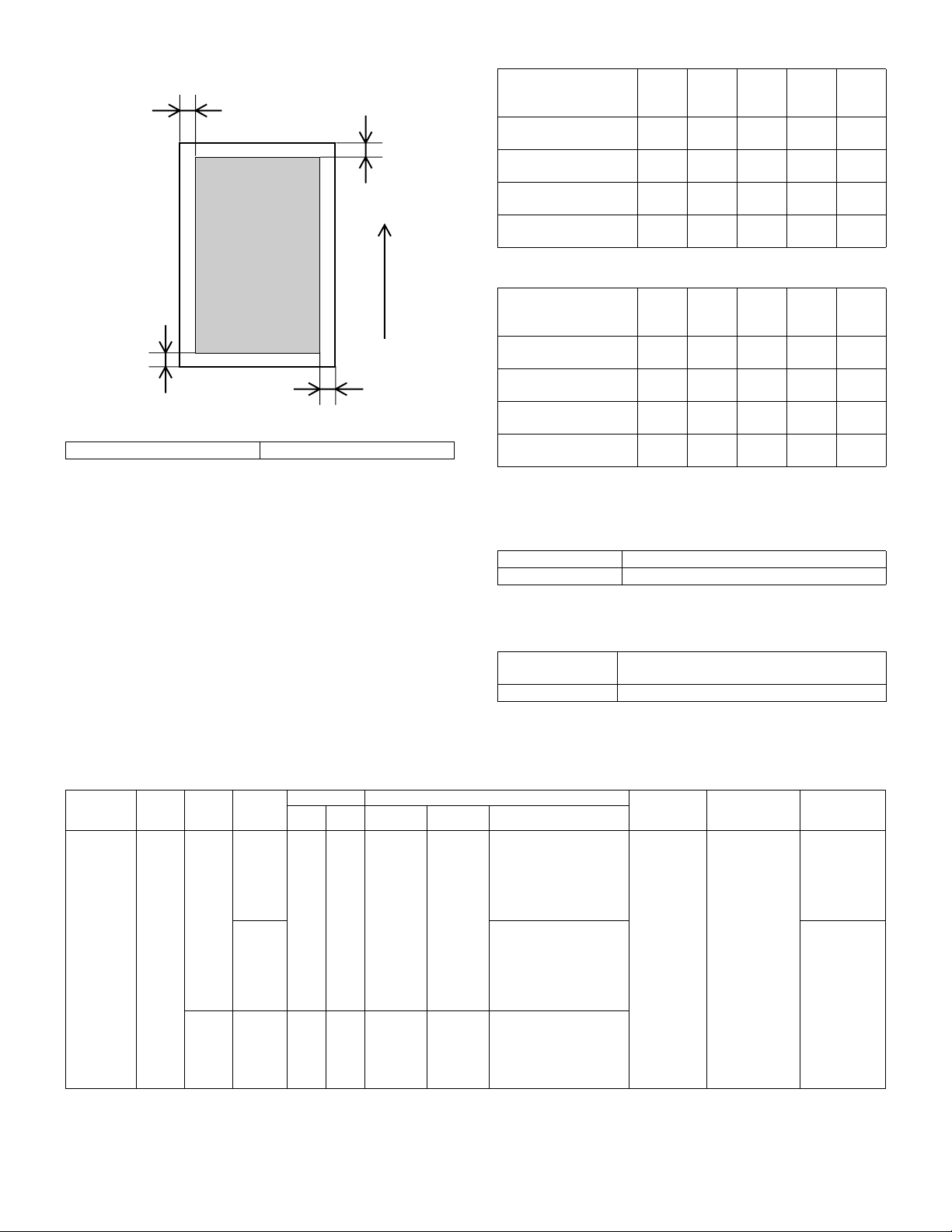
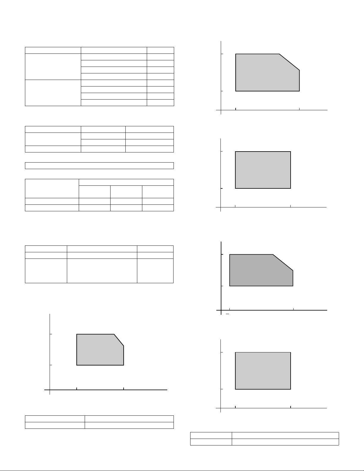
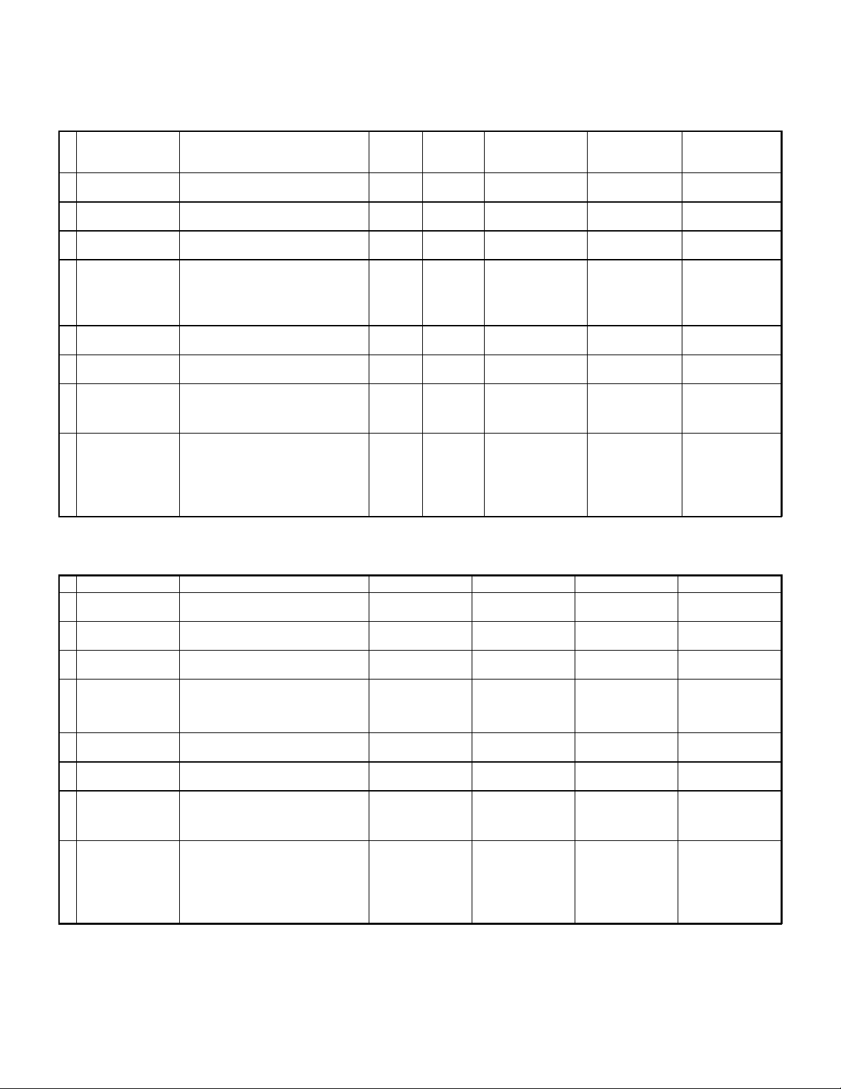
(6) Copy area
C
(Front edge)
Printed image
(image area)
B
(Rear edge)
Dimensions show void area
Copy area 297 × 432mm
• Image loss
Front
edge
One side copy
A
(excluding A3 (11 × 17))
One side copy for A3
(11 × 17)
Max.
5mm
Max.
5mm
Duplex copying Max.
5mm
OHP copying Max.
10mm
∗
0mm image loss for A3 originals and A3 wide copying.
Feeding
direction
• Void area
Front
edge
One side copy
(excluding A3 (11 × 17))
One side copy for A3
(11 × 17)
D
Duplex copying Max.
Max.
5mm
Max.
5mm
5mm
OHP copying Max.
10mm
(A)
(A)
Rear
edge
(B)
Max.
5mm
Max.
7mm
Max.
7mm
Max.
10mm
Rear
edge
(B)
Max.
5mm
Max.
7mm
Max.
7mm
Max.
10mm
Total
(C + D)
Max.
6mm
Max.
6mm
Max.
6mm
Max.
6mm
Total
(C + D)
Max.
6mm
Max.
6mm
Max.
6mm
Max.
6mm
Left
edge
(C)
Max.
3.0mm
Max.
3.0mm
Max.
3.0mm
Max.
3.0mm
Left
edge
(C)
Max.
3.0mm
Max.
3.0mm
Max.
3.0mm
Max.
3.0mm
Right
edge
(D)
Max.
3.0mm
Max.
3.0mm
Max.
3.0mm
Max.
3.0mm
Right
edge
(D)
Max.
3.0mm
Max.
3.0mm
Max.
3.0mm
Max.
3.0mm
(7) Languages supported
Japanese, English (USA/UK), German, French, Spanish, Italian,
Dutch, Swedish, Norwegian, Finnish, Danish
(8) Internal auditor
Format Key operation/card operation (optional)
No. of departments 400 (200 with card type)
B. Paper feeding, paper conveyance, and discharge section
(1) Paper feeding performance
a. Paper feed ability
Paper feed
mode
(section)
Manual feed
section
(Multi paper
feed)
Feed
method
— AB
Paper
type
Series
Inch
Series
Location
Japan — — A6 (A6R)
Others A3 wide, A3, B4, A4, A4R,
Dimensions Paper size
Min. Max. Min. Max. Paper sizes
Postcard
— — 8.5 × 5.5 12 × 18 12 × 18, 11 × 17, 8.5 × 14,
A3 wide
(12 × 18)
A3 wide, A3, B4, A4, A4R,
B5, B5R, A5, Postcard,
11 × 17, 8.5 × 14, 8.5 × 11
(Paper guide display: 11,
8.5, A3 wide, A3, B4, A4,
A4R, B5, B5R, A5, A5R,
B6R, A6R, Postcard)
B5, A5, A6R, 11 × 17,
8.5 × 14, 8.5 × 11,
7.25 × 10.5R
(Paper guide display: 11,
8.5, A3 wide, A3, B4, B5,
A4R, A5, B5R, A5R)
8.5 × 11, 8.5 × 11R,
8.5 × 5.5, 7.25 × 10.5R, A3,
B4, A4, B5, A6R
(Paper guide display: 12,
11, 8.5, 5.5, A3, B4, A4, B5)
3. Engine specifications
A. Operation (display/operation) section
Display Large mono-color LCD display (AR-C150/C160)
Large color LCD display (AR-C250)
Operating procedure Touch-panel input
Paper weight Capacity Note
60 to 200g/m
(16 to 55lbs.)
(AR-C150/
C250)
60 to 280g/m
(16 to 75 lbs)
(AR-C160)
2
50 sheets (6mm)
(max. 80g/m
paper)
2
Special paper
2
(OHP film),
(recommended
product),
Postcard and
thick paper
Special paper
(OHP film) and
thick paper
2 – 8
Page 17
Paper feed
mode
(section)
Manual feed
section
(Single
paper feed)
1st to 4th
cassette
feeding unit
Feed
method
— AB
— AB
Paper
type
Series
Inch
Series
Series
Inch
Series
Location
Japan — — A6 (A6R)
Others A3 wide, A3, B4, A4, A4R,
Japan — — A5 A3 A3, B4, A4, A4R, B5, B5R,
Others A3, B4, A4, A4R, B5, A5,
Dimensions Paper size
Min. Max. Min. Max. Paper sizes
Postcard
— — 8.5 × 5.5 12 × 18 12 × 18, 11 × 17, 8.5 × 14,
— — 8.5 × 5.5 11 × 17 11 × 17, 8.5 × 14, 8.5 × 13,
A3 wide
(12 × 18)
A3 wide, A3, B4, A4, A4R,
B5, B5R, A5, Postcard,
11 × 17, 8.5 × 14, 8.5 × 11
(Paper guide display: 11,
8.5, A3 wide, A3, B4, A4,
A4R, B5, B5R, A5, A5R,
B6R, A6R, Postcard)
B5, A5, A6R, 11 × 17,
8.5 × 14, 8.5 × 11,
7.25 × 10.5R
(Paper guide display:)
8.5 × 11, 8.5 × 11R,
8.5 × 5.5, 7.25 × 10.5R, A3,
B4, A4, B5, A6R
(Paper guide display: 12,
11, 8.5, 5.5, A3, B4, A4, B5)
A5, EXTRA
8.5 × 11
8.5 × 11, 8.5 × 11R,
8.5 × 5.5, A4, EXTRA
60 to 200g/m
(16 to 55lbs.)
(AR-C150/
C250)
60 to 280g/m
(16 to 75lbs.)
(AR-C160)
60 to 105g/m
(16 to 28lbs.)
b. Document detection
Paper feed
mode (section)
Manual feed
section
Paper
type
AB
Series
Inch
Series
Location of
use
Detection size
Japan A3 wide, A3, B4, A4, A4R, B5, B5R, A5,
Postcard, 11 × 17, 8.5 × 14, 8.5 × 11
Others A3 wide, A3, B4, A4, A4R, B5, A5, A6R,
11 × 17, 8.5 × 14, 8.5 × 11, 7.25 × 10.5R
12 × 18, 11 × 17, 8.5 × 14, 8.5 × 11,
8.5 × 11R, 8.5 × 5.5, A3, B4, A4, B5, A6R,
Paper detection size and
detection method
Electrical resistance
changes according to
position of paper width
guide (volume sensor)
7.25 × 10.5R
1st to 4th
cassette
feeding unit
∗
When setting the paper size switch to EXTRA, it is necessary to set the paper size by key operation.
∗
For A and B sizes (excluding Japan), it is necessary to set the paper size switch to EXTRA for 13" and B5R.
(2) Finishing performance
AB
Series
Inch
Series
Japan A3, B4, A4, A4R, B5, B5R, A5, EXTRA Detection method by
Others A3, B4, A4, A4R, B5, A5, 8.5 × 11, EXTRA
11 × 17, 8.5 × 14, 8.5 × 13, 8.5 × 11,
8.5 × 11R, 8.5 × 5.5, A4, EXTRA
switch signal combination
(switches paper detection
block position)
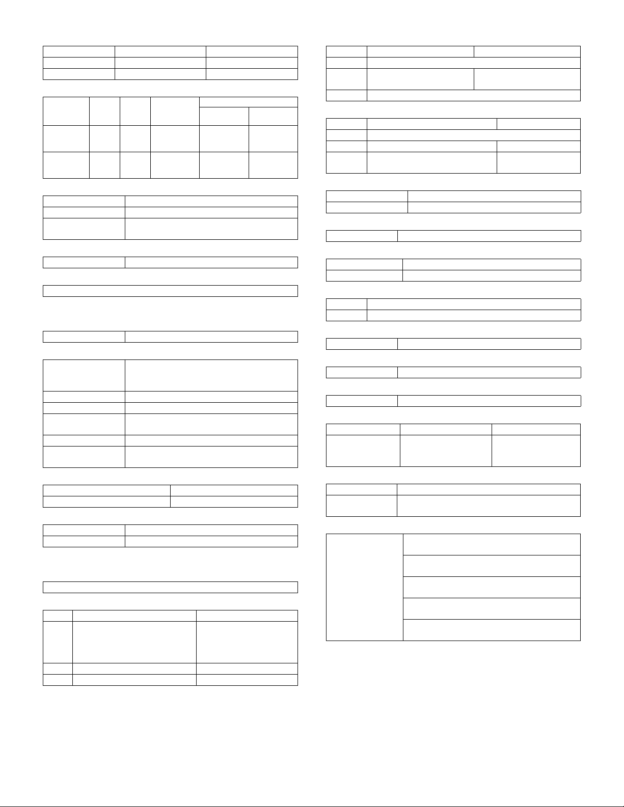
c. Scanning area
Facing mode Paper size Paper weight Capacity Note
Face up All paper
sizes
All paper sizes
that can be fed
250 sheets
C. Scanner section
(1) Type
Scanning method By 3-color (RGB) CCD image sensor
(2) Original standard position, scanning size, and
scanning area
a. Original standard position
Left-center
b. Scanning size
Max. original size AB Series A3
Inch Series 11 × 17
432 mm
Paper weight Capacity Note
2
50 sheets (6mm)
(max. 80g/m
paper)
2
2
500 sheets × 3 (4)
(max. 80g/m2
paper)
500 sheets × 3 (4)
(max. 80g/m
paper)
Size switching
method
2
2
Special paper
(OHP film),
Postcard and
thick paper
Special paper
(OHP film) and
thick paper
Note
Aligns with paper
width guide (sliding
type)
Aligns universal
guide (sliding type)
Remaining
amount detector
Center
(3) Resolution
2 – 9
297 mm
Main scanning direction Sub scanning direction
Basic resolution Basic resolution
600dpi 600dpi
Page 18
(4) Gradation
Input Output
Monochrome 256 gradations (8bit) 256 gradations (8bit)
Color 256 gradations (8bit) 256 gradations (8bit)
(5) Scanning speed
Scan mode Scan Return
Color 117
Monochrome 117
mm/sec
mm/sec
468
mm/sec
468
mm/sec
Scans per
minute
15 sheets/min
16 sheets/min
(AR-C160)
15 sheets/min
16 sheets/min
(AR-C160)
Original size
A4
(11" × 8.5")A3(11" × 17")
15 sheets/min
16 sheets/min
(AR-C160)
15 sheets/min
16 sheets/min
(AR-C160)
7 sheets/min
7 sheets/min
(6) Light source
Type Halogen lamp
Drive voltage 70V
Power consumption 130W (AR-C150)
170W (AR-C250/C160)
(7) Scanning sensor
Type 3-line color CCD
(8) Color separation method
Color separation by 3-color (RGB) CCD image sensor
D. Scanner section
(1) Type
Type Laser scanning
(2) Laser unit specifications
Speed of rotation 27,600rpm (AR-C150/C250)
Color mode 27,600rpm (AR-C160)
Monochrome mode 33,000rpm (AR-C160)
Mirror surfaces 6 surfaces
Laser power 5mW
Laser beam size 65
Laser wavelength 785
Scan width
× 85µm (AR-C150/C250)
70µm (AR-C160)
×
60
µm
AB Series: 420mm Inch Series: 432mm
(sub scan direction)
(3) Resolution
Main scanning direction Sub scanning direction
600dpi 600dpi
(4) Gradation
Monochrome 256 gradations (8bit)
Color 256 gradations (8bit)
E. Image processing section
(1) Imaging speed
117 mm/sec
(2) Photosensitive drum
Black (AR-C160 only)
Type OPC
Life 40,000 sheets 80,000 sheets
Form Cartridge Cartridge
φ40mm (3 pieces) (C, M, Y)
(AR-C160)
OPC
φ40mm (4 pieces) (C, M, Y,
K) (AR-C150/C250)
φ40mm (1 pieces) (K)
OPC
(3) Toner
Black Color (C, M, Y)
Type —
Capacity 600g (AR-C150/C250)
650g (AR-C160/C250)
267g each (AR-C150)
300g each (AR-C250/C160)
Form Cartridge
(4) Developer
Black Color (C, M, Y)
Type Ferrite type
Capacity 650g 650g each
Life 40,000 sheets (AR-C150/C250)
40,000 sheets each
80,000 sheets (AR-C160)
(5) Charging system
Charging system DC negative scorotron (saw tooth electrode)
Voltage – 320V to – 830V
(6) Exposure
Method Exposure from laser diode
(7) Developing system
Developing system Dry, 2-component magnetic brush development
Voltage – 120V to – 600V
(8) Transfer
Method DC positive static electricity transfer (transfer belt method)
Voltage 1.75 to 5KV
(9) Paper separation system
Method Curvature release + Separation pawl
(10) Discharging
Method Discharging lamp method
(11) Cleaning
Method Blade method
(12) Toner compartment capacity
Black Color (C, M, Y)
Capacity 600g (AR-C150/C250)
650g (AR-C160)
267g (AR-C150)
300g (AR-C250/
C150/C160)
(13) Waste toner collector capacity
Capacity —
Printed sheets 40K (Conditions of each color 5% coverage, total
20% coverage)
(14) Correction functions
Correction functions Toner density correction (toner density control
level correction)
Drum sensitivity correction (laser power control
level correction)
Transfer-ability correction (transfer voltage
control level correction)
Developing-ability correction (developing bias
voltage control level correction)
Halftone correction (laser power duty control
level correction)
2 – 10
Page 19
F. Fuser section
(1) Type
Fusing system Heat roller system (oil usage)
(2) Lamp
Main unit
voltage
ratings
100V Main heater lamp Halogen lamp 100V 1000W
110V Main heater lamp Halogen lamp — —
120V Main heater lamp Halogen lamp 120V 1200W
127V Main heater lamp Halogen lamp — —
220 to 230V Main heater lamp Halogen lamp 230V 1300W
240V Main heater lamp Halogen lamp 230V 1300W
Lamp Type
Sub heater lamp Halogen lamp 100V 700W
Sub heater lamp Halogen lamp — —
Sub heater lamp Halogen lamp 120V 700W
Sub heater lamp Halogen lamp — —
Sub heater lamp Halogen lamp 230V 700W
Sub heater lamp Halogen lamp 230V 700W
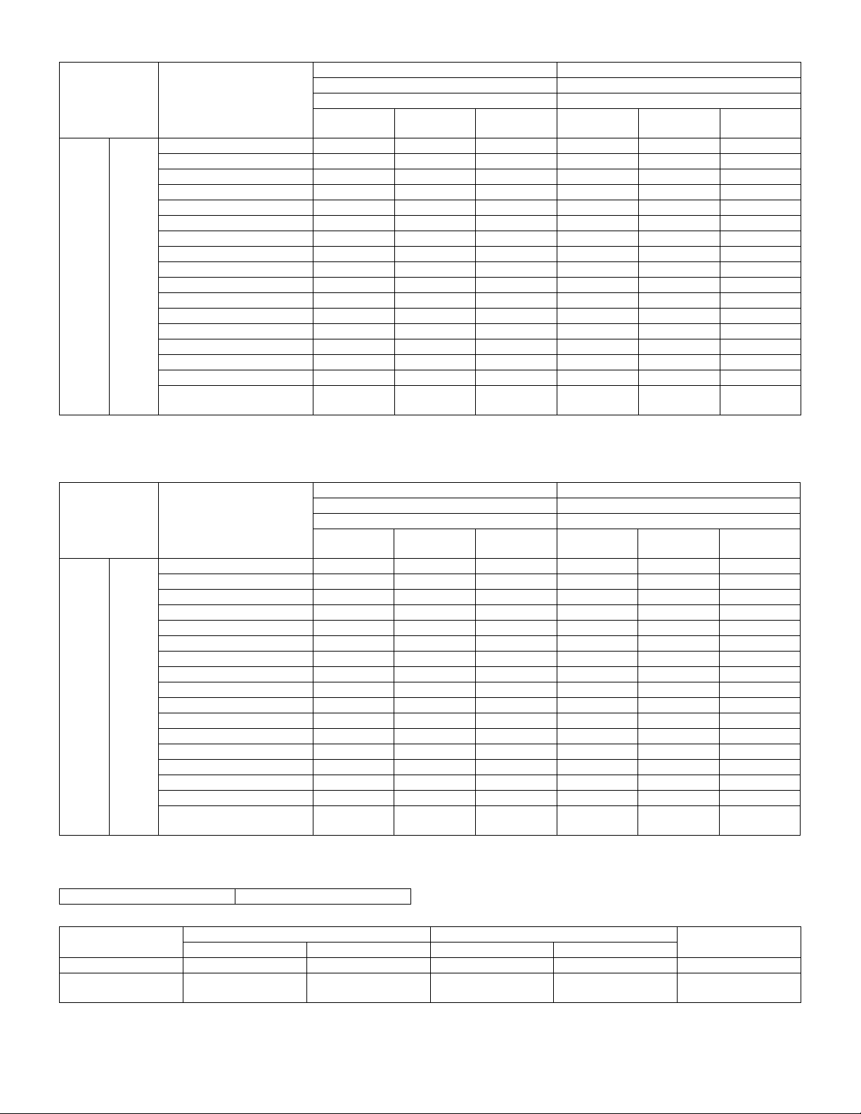
(3) Fuser temperature
(AR-C100/C150)
Mode
Ready
condition
Copy/Print
mode
Pre-heat
mode
Sleep
mode
Ready condition control temperature (HL1) Upper heat roller 187 187 187 177 177 187 187 187 187
Ready condition control temperature (HL2) Lower heat roller 142 142 142 132 132 142 142 142 142
Normal mode control temperature (HL1) Upper heat roller 180 180 180 170 170 180 180 180 180
Normal mode control temperature (HL2) Lower heat roller 135 135 135 125 125 135 135 135 135
Thick paper mode control temperature (HL1) Upper heat roller 200 200 200 200 200 200 200 200 200 AR-C150 only
Thick paper mode control temperature (HL2) Lower heat roller 155 155 155 155 155 155 155 155 155 AR-C150 only
OHP mode control temperature (HL1) Upper heat roller 180 180 180 180 180 180 180 180 180 AR-C150 only
OHP mode control temperature (HL2) Lower heat roller 175 175 175 175 175 175 175 175 175 AR-C150 only
Energy saving mode control temperature (HL1) Upper heat roller
Control temperature when resetting from preheat to B/W (HL1)
HL1 Upper heat roller OFF OFF OFF OFF OFF OFF OFF OFF OFF
HL2 Lower heat roller OFF OFF OFF OFF OFF OFF OFF OFF OFF
(AR-C250/C160)
Mode
Ready
condition
Copy/Print
mode
Pre-heat
mode
Sleep
mode
Ready condition control temperature (HL1) Upper heat roller 177 177 177 177 177 177 177 177 177
Ready condition control temperature (HL2) Lower heat roller
Normal mode control temperature (HL1) Upper heat roller 170 170 170 170 170 170 170 170 170
Normal mode control temperature (HL2) Lower heat roller
Thick paper mode 1 control temperature (HL1) Upper heat roller 185 185 185 185 185 185 185 185 185
Thick paper mode 1 control temperature (HL2) Lower heat roller 155 155 155 155 155 155 155 155 155
Thick paper mode 2 control temperature (HL1) Upper heat roller 200 200 200 200 200 200 200 200 200
Thick paper mode 2 control temperature (HL2) Lower heat roller 155 155 155 155 155 155 155 155 155
OHP mode control temperature (HL1) Upper heat roller 180 180 180 180 180 180 180 180 180
OHP mode control temperature (HL2) Lower heat roller 175 175 175 175 175 175 175 175 175
Energy saving mode control temperature (HL1) Upper heat roller 136
Control temperature when resetting from preheat to B/W (HL1)
HL1 Upper heat roller OFF OFF OFF OFF OFF OFF OFF OFF OFF
HL2 Lower heat roller OFF OFF OFF OFF OFF OFF OFF OFF OFF
(4) Heat roller
Type Silicone rubber roller φ40mm (AR-C150)
Life 40K
φ50mm (AR-C250/C160)
(5) Pressure roller
Type Silicone rubber roller
Life 40K
φ40mm (AR-C150)
φ50mm (AR-C250/C160)
Lamp rating
Vol tag e
Power
consumption
Upper heat roller
Upper heat roller 148
U.S.A Canada Inch Japan AB_B Europe U.K Aus. AB_A
140 140 140
155 155 155
U.S.A Canada Inch Japan AB_B Europe U.K Aus. AB_A
132 132 132
125 125 125
(146)
(158)
136
(146)
148
(158)
Control temperature
140
(137)
155
(152)
Control temperature
140
(132)
140
(125)
136
136
(146)
(146)
148
148
(158)
(158)
140 140 140 140 140
155 155 155 155 155
140
132 132 132 132
(132)
140
125 125 125 125
(125)
136
136
136
136
(146)
148
(158)
(146)
148
(158)
(146)
148
(158)
(146)
148
(158)
136
(146)
148
(158)
(6) Release method
Forced release by releasing tabs
NOTE
( ) AR-C100
( ) AR-C100
NOTE
( ) AR-C160
( ) AR-C160
( ) AR-C160
( ) AR-C160
2 – 11
Page 20
G. Drive section
Drive section Motor name Motor type
Toner hopper
(C, M, Y, K)
Photosensitive drum
(C, M, Y, K)
Image scanner Scanner motor Stepping motor
Developing
(C, M, Y, K)
Paper feed and
conveyance
Transfer belt Transfer belt motor Stepping motor
Fusing Fusing motor DC brush-less motor
Toner motor
(Y, M, C, K)
Drum motor
(Y, M, C, K)
Developing motor
(Y, M, C, K)
Paper feed motor DC brush-less motor
Synchronous motor
Stepping motor
DC brush-less motor
H. Engine controller
Processor M68334
I. Image processing controller
Processor MCF5202
J. Memory
Type Capacity Memory contents Location
DRAM 128MB (AR-C150/C160)
Flash
ROM
EEPROM 64Kbit (AR-C100)
256MB (AR-C250)
32Mbit Program data ICU MAIN
16Mbit (AR-C150/C250/
C160)
8Mbit (AR-C100)
16Mbit (AR-C150/C160)
16Mbit × 2 (AR-C250)
256Kbit (AR-C150/C160/
C250)
64Kbit Setting,
Image data ICU MAIN
Program data PCU PWB
Program data Operation
Setting,
adjustment,
counter data, etc.
adjustment,
counter data, etc.
PWB
PWB
control PWB
PCU PWB
ICU MAIN
PWB
K. Power source
(1) DC power supply
(AR-C150/C250)
Type
DC power
supply
(AR-C160)
DC power supply 24V 15A
Main 24V 15A
Sub 26V 0.5A
Type
Voltage Capacity (current) Note
5.1V 7.5A
3.4V 5.5A
5V2 1.1A
5Vs 0.1A
Voltage Capacity (current) Note
5.1V 7.5A
3.4V 5.5A
(2) Dehumidifier functionality
Section Paper conveyor section
Method Surface heater Surface heater
(Japan only)
* With ON/OFF switch
Output
Output
Image scanner section
(optional outside of Japan)
(3) Operating voltage/power consumption
(AR-C150/C250)
Power consumption
Power supply voltage/
frequency
100V 50/60Hz Max. 101W — Max. 10W 1500W ——— 1500W
110V 50/60Hz Max. 101W — Max. 10W 1500W ——— 1500W
120V 50/60Hz Max. 101W — Max. 10W 1500W ——— 1500W
127V 50/60Hz Max. 101W — Max. 10W 1500W ——— 1500W
220 to 230V 50/60Hz Max. 101W — Max. 10W 1800W — 1175W — 1800W
240V 50/60Hz Max. 101W — Max. 10W 1800W — 1325W — 1800W
(AR-C160)
Power supply voltage/
frequency
100V 50/60Hz Max. 128.2wh — Max. 15W 1500W ——— 1500W
110V 50/60Hz Max. 128.2wh — Max. 15W 1500W ——— 1500W
120V 50/60Hz Max. 128.2wh — Max. 15W 1500W ——— 1500W
127V 50/60Hz Max. 128.2wh — Max. 15W 1500W ——— 1500W
220 to 230V 50/60Hz Max. 128.2wh — Max. 15W 1800W — 1175W — 1800W
240V 50/60Hz Max. 128.2wh — Max. 15W 1800W — 1325W — 1800W
Preheat
condition
Preheat
condition
Main unit With full options
Ready
condition
Ready
condition
Sleep mode
condition
Main unit With full options
Sleep mode
condition
Max.
Power consumption
Max.
Preheat
condition
Preheat
condition
Ready
condition
Ready
condition
Sleep mode
condition
Sleep mode
condition
Max.
Max.
2 – 12
Page 21
4. Safety and environmental protection
standards
A. Safety standards
Item Standard Country
Safety standards S mark (Electrical regulations) Japan
UL U.S.A
SEMKO Sweden
GS Mark Germany
Environmental standards FCC U.S.A
VCCI Japan
CE Europe
C-tick Australia
B. Environmental standards
(1) Power consumption and environmental standards
Item Standard Country
Power consumption Energy Star Japan, U.S.A, Europe
ECP, Nordic Canada
Environmental standards Swan, Nordic Sweden
(2) Ozone level
Max. 0.02mg/m
(3) Noise level
Noise mode
Noise power level Max. 66dB Max. 40dB —
Noise pressure level ———
3
Main unit
During
operation
Ready
condition
Sleep mode
condition
5. Ambient conditions
A. Space required
(1) Area required
AR-C150/C160/C250 AR-C100
Main unit 1412 × 695mm (55.6" × 27.4") 1220 × 695mm
With full options (With AR-SS2)
B. Operating ambient conditions
(1) Temperature/Humidity
1504 × 695mm (59.2" × 27.4")
(With AR-FN4)
1690 × 695mm (66.6" × 27.4")
—
C. Ambient storage conditions
Humidity
RH
90%
10%
Humidity
RH
90%
20%
–10˚C50˚C
Consumable items (unopened)
–5˚C40˚C
Main unit
40˚C, 90%
Temperature
40˚C, 90%
Temperature
D. Ambient conditions for transporting
Humidity
RH
90%
20%
Main unit
30˚C, 90%
50˚C, 60%
45˚C, 60%
Humidity
RH
80%
30˚C, 80%
20%
15˚C 35˚C
Temperature
(2) Power supply voltage and frequency
Power supply voltage Rated voltage ± 10%
Power supply frequency Rated frequency ± 2%
35˚C, 60%
20˚C45˚C
Humidity
RH
90%
10%
–5˚C40˚C
Temperature
Consumable items
Temperature
E. Standard temperature and humidity
Temperature 20 to 25°C
Humidity 65 ± 5%
2 – 13
40˚C, 90%
Page 22
[3] CONSUMABLE PARTS
1. Consumable parts list
AR-C150 Supply List (U.S.A./CANADA)
NAME CONTENT(S)
1 Color Toner (cyan) "Toner Cartridge (cyan) (267g),
Instruction Sheet"
2 Color Toner (magenta) "Toner Cartridge (magenta) (267g),
Instruction Sheet"
3 Color Toner (yellow) "Toner Cartridge (yellow) (267g),
Instruction Sheet"
4 Toner (black) "Toner Cartridge (black) (600g),
Instruction Sheet"
5 Color Developer kit [Developer (cyan × 1, magenta × 1,
yellow × 1) (650g each)
6 Black Developer kit [Developer (black) (650g) × 1 × 10 40K × 10 AR-C15MD1 204 × 391 × 290/9.10 (AR-C15ND1) × 10 =
7 Drum Unit Drum Unit × 1 40K AR-C15DU 402 × 568 × 198/6.73 Not applicable for
(Drum/Unit Parts included) × 1
Color Seal (C, M, Y, Bk each × 2)
8 Drum Kit Drum × 1 40K AR-C15DK 418 × 146 × 519/4.60 Not applicable for
Cleaning Blade × 1
Toner Receiving Seal × 1
Charger Unit × 1
Color Seal (C, M, Y, Bk each × 1)
LIFE
Note 1)
× 10 4K Note 1)
× 10
× 10 4K Note 1)
× 10
× 10 4K Note 1)
× 10
× 10 8K Note 1)
× 10
× 3 40K
each × 3
Model
AR-C15MT6 329 × 590 × 218/5.62 A (AR-C15NT6) × 10 =
AR-C15MT7 329 × 590 × 218/5.62 A (AR-C15NT7) × 10 =
AR-C15MT8 329 × 590 × 218/5.62 A (AR-C15NT8) × 10 =
AR-C15MT1 429 × 610 × 246/10.97 A (AR-C15NT1) × 10 =
AR-C15MD9 294 × 391 × 170/7.71 (AR-C15ND9) × 3 =
Note 1) A4 document with 10% coverage
Note 2) Inner carton printed in 2 languages including English and French
AR-C150/250 Supply List (U.S.A/Canada)
NAME CONTENT (S) LIFE MODEL INCOMPATIBILITY REMARK
1 Color Toner (cyan) Toner Cartridge (cyan) (300g),
Instruction Sheet
2 Color Toner (magenta) Toner Cartridge (magenta) (300g),
Instruction Sheet
3 Color Toner (yellow) Toner Cartridge (yellow) (300g),
Instruction Sheet
4 Toner (black) Toner Cartridge (black) (600g),
Instruction Sheet
5 Color Developer kit [Developer (cyan × 1, magenta × 1,
yellow × 1) (650g each) ]
6 Black Developer kit [Developer (black) (650g) × 1] × 10 40K × 10 AR-C15MD1 (AR-C15ND1) × 10 =
7 Drum Unit Drum Unit × 1 40K AR-C25DU Not applicable for
(Drum/Unit Parts included) × 1
Color Seal (C, M, Y, Bk each × 2)
8 Drum Kit Drum × 1 40K AR-C25DK Not applicable for
Cleaning Blade × 1
Toner Receiving Seal × 1
Charger Unit × 1
Color Seal (C, M, Y, Bk each × 1)
Note 1) A4 document with 10% coverage
Note 2) Inner carton printed in 2 languages including English and French
Note 3) A4 document with 6% coverage
× 10 4.85K × 10 Note 1) AR-C25MT6 A (AR-C25NT6) × 10 =
× 10 4.85K × 10 Note 1) AR-C25MT7 A (AR-C25NT7) × 10 =
× 10 4.85K × 10 Note 1) AR-C25MT8 A (AR-C25NT8) × 10 =
× 10 8.64K × 10 Note 1)
21.7K × 10 Note 3)
× 3 40K each color × 3 AR-C15MD9 (AR-C15ND9) × 3 =
DIMENSIONS
(W × D × H): mm
/WHIGHT: kg
AR-C25MT1 A (AR-C25NT1) × 10 =
INCOMPATIBILITY REMARK
AR-C15MT6
AR-C15MT7
AR-C15MT8
AR-C15MT1
The AR-C25MT1 or
AR-C16MT1 can be
used.
AR-C15MD9
AR-C15MD1
AR-C250, AR-C160
AR-C250, AR-C160
AR-C25MT6
AR-C25MT7
AR-C25MT8
AR-C25MT1
The AR-C16MT1 can
be used.
AR-C15MD9
AR-C15MD1
black in AR-C160.
black in AR-C160.
3 – 1
Page 23
AR-C150/C250 supply system (USA/Canada)
No. Name Content Life Model Remark
1 Developer unit kit Developer unit × 4— AR-DW1
2 Waste toner container kit Drum waste toner container (AS) × 1 40K AR-C15HB 5% coverage of each of C/M/Y/K, total 20% coverage
Transfer waste toner tank unit × 1
3 Fusing oil Fusing oil (800g) × 10 40K × 10 AR-C15LL AR-C15LL = AR-C15SL × 10
4 Upper heat roller kit Upper heat roller unit × 1 40K AR-C15UH
Upper cleaning roller × 1
5 Lower heat roller kit Lower heat roller unit × 1 40K AR-C15LH
Fusing separation pawl lower × 5
6 Fusing oil applying kit Oil applying unit × 1 40K AR-C15KH
Oil filter unit × 1
Applying unit mini oil bottle × 1
7 Filter kit Process ozone filter × 2 80K AR-C15FL
Toner duct ozone filter × 1
Toner filter × 1
8 Transfer belt kit Transfer belt × 1 160K AR-C15TT
Belt separation pawl × 2
9 Transfer roller kit Transfer blade × 1 80K AR-C15TX
Transfer roller × 4
10 Staple cartridge Staple cartridge (SF-SC11) × 3 5,000 × 3 SF-SC11 For AR-SS2. Common with FN1.
11 Fusing unit Fusing unit
(Except for motor, PWB,
upper/lower lamps)
12 Transfer unit Transfer unit
(Except for motor)
13 DV seal kit DV seal unit (assemble) × 3 80K AR-C15DS
14 Staple cartridge Staple cartridge 3,000 × 3 AR-SC1 For AR-FN4
× 1
× 1 AR-C15TU (For servicing)
AR-C25UH
AR-C25LH
AR-C25KH
AR-C15FU
AR-C25FU
For AR-C150
For AR-C250
For AR-C150
For AR-C250
For AR-C150
For AR-C250
(For servicing)
For AR-C150
For AR-C250
AR-C160 Supply List (U.S.A/Canada)
NAME CONTENT (S) LIFE MODEL INCOMPATIBILITY REMARK
1 Color Toner (cyan) Toner Cartridge (cyan) (300g),
Instruction Sheet
2 Color Toner (magenta) Toner Cartridge (magenta) (300g),
Instruction Sheet
3 Color Toner (yellow) Toner Cartridge (yellow) (300g),
Instruction Sheet
4 Toner (black) Toner Cartridge (black) (650g),
Instruction Sheet
5 Color Developer kit [Developer (cyan × 1, magenta × 1,
yellow × 1) (650g each) ]
6 Black Developer kit [Developer (black) (650g) × 1] × 10 80K × 10 AR-C16MD1 (AR-C16ND1) × 10 = AR-C16MD1
7 Drum Unit Drum Unit × 1 40K AR-C25DU Use for C, M, Y
(Drum/Unit Parts included) × 1
Color Seal (C, M, Y, each × 2)
8 Drum Kit Drum (Color) × 1 40K AR-C25DK Use for C, M, Y
Cleaning Blade × 1
Toner Receiving Seal × 1
Charger Unit × 1
Color Seal (C, M, Y, each × 1)
9 Drum Drum (Black) 80K AR-C16DR Use for Black
10 Main charger kit Main charger unit × 1 40K AR-16MK Use for Black
Cleaning blade × 1
Toner receving seal × 1
RS roller cleaner × 1
Note 1) A4 document with 10% coverage
Note 2) Inner carton printed in 2 languages including English and French
Note 3) A4 document with 6% coverage
× 10 4.85K × 10
Note 1)
× 10 4.85K × 10
Note 1)
× 10 4.85K × 10
Note 1)
× 10 21.7K × 10
Note 3)
× 3 40K each
color × 3
AR-C25MT6 A (AR-C25NT6) × 10 = AR-C25MT6
AR-C25MT7 A (AR-C25NT7) × 10 = AR-C25MT7
AR-C25MT8 A (AR-C25NT8) × 10 = AR-C25MT8
AR-C16MT1 A (AR-C16NT1) × 10 = AR-C16MT1
The AR-C25MT1 or AR-C16MT1
can be used.
AR-C15MD9 (AR-C15ND9) × 3 = AR-C15MD9
Not applicable for AR-C150 and
AR-C250.
Not applicable for AR-C150 and
AR-C250.
Not applicable for AR-C150 and
AR-C250.
3 – 2
Page 24
AR-C160 supply system (USA/Canada)
No. Name Content Life Model Remark
1 Developer unit kit Developer unit × 4— AR-DW1
2 Waste toner container kit Drum waste toner container (AS) × 1 40K AR-C15HB 5% coverage of each of C/M/Y/K, total 20% coverage
Transfer waste toner tank unit × 1
3 Fusing oil Fusing oil (800g) × 10 40K × 10 AR-C15LL AR-C15LL = AR-C15SL × 10
4 Upper heat roller kit Upper heat roller unit × 1 40K AR-C16UH For AR-C160
Upper cleaning roller × 1
5 Lower heat roller kit Lower heat roller unit × 1 40K AR-C16LH For AR-C160
Fusing separation pawl lower × 5
6 Fusing oil applying kit Oil applying unit × 1 40K AR-C15KH
Oil filter unit × 1
Applying unit mini oil bottle × 1
7 Filter kit Process ozone filter × 2 80K AR-C15FL
Toner duct ozone filter × 1
Toner filter × 1
8 Transfer belt kit Transfer belt × 1 160K AR-C16TT
Transfer roller kit Transfer roller × 4
9 Staple cartridge Staple cartridge (SF-SC11) × 3 5,000 × 3 SF-SC11 For AR-SS2. Common with FN1.
10 Fusing unit Fusing unit
(Except for motor, PWB,
upper/lower lamps)
11 Transfer unit Transfer unit
(Except for motor)
12 DV seal kit DV seal unit (assemble) × 3 80K AR-C15DS
13 Staple cartridge Staple cartridge 3,000 × 3 AR-SC1 For AR-FN4
14 Transfer belt cleaning blade kit Transfer belt cleaning blade × 1 80K AR-C16TG AR-C16TG = AR-C160G × 10 (for USA)
Transfer belt cleaning blade kit Transfer belt cleaning blade × 1 80K AR-C16TK AR-C16TK = AR-C160K × 10 (for Canada)
× 1 AR-C16FU (For servicing)
× 1 AR-C16TU (For servicing)
AR-C25KH
For AR-C150
For AR-C250
For AR-C160
AR-C150 Supply List (Europe/Australia/New Zealand)
NAME CONTENT(S)
1 Color Toner (cyan) "Toner Cartridge (cyan) (267g),
Instruction Sheet"
2 Color Toner (magenta) "Toner Cartridge (magenta) (267g),
Instruction Sheet"
3 Color Toner (yellow) "Toner Cartridge (yellow) (267g),
Instruction Sheet"
4 Toner (black) "Toner Cartridge (black) (600g),
Instruction Sheet"
5 Color Developer kit [Developer (cyan × 1, magenta × 1,
yellow × 1) (650g each)
6 Black Developer kit [Developer (black) (650g) × 1 × 10 40K AR-C15LD1 204 × 391 × 290/9.10 (AR-C15DV1) × 10 =
7 Drum Unit Drum Unit × 1 40K AR-C15DU 402 × 568 × 198/6.73 Not applicable for
(Drum/Unit Parts included) × 1
Color Seal (C, M, Y, Bk each × 2)
8 Drum Kit Drum × 1 40K AR-C15DK 418 × 146 × 519/4.60 Not applicable for
Cleaning Blade × 1
Toner Receiving Seal × 1
Charger Unit × 1
Color Seal (C, M, Y, Bk each × 1)
LIFE
Note 1)
× 10 4K Note 1)
× 10
× 10 4K Note 1)
× 10
× 10 4K Note 1)
× 10
× 10 8K Note 1)
× 10
× 3 40K
each × 3
Model
AR-C15LT6 329 × 590 × 218/5.62 B (AR-C15T6) × 10 =
AR-C15LT7 329 × 590 × 218/5.62 B (AR-C15T7) × 10 =
AR-C15LT8 329 × 590 × 218/5.62 B (AR-C15T8) × 10 =
AR-C15LT1 429 × 610 × 246/10.97 B (AR-C15T1) × 10 =
AR-C15LD9 294 × 391 × 170/7.71 (AR-C15DV9) × 3 =
Note 1) A4 document with 10% coverage
Note 2) Inner carton printed in 4 languages
DIMENSIONS
(W × D × H): mm
/WHIGHT: kg
INCOMPATIBILITY REMARK
AR-C15LT6
AR-C15LT7
AR-C15LT8
AR-C15LT1
The AR-C16LT1 can
be used.
AR-C15LD9
AR-C15LD1
AR-C250, AR-C160
AR-C250, AR-C160
3 – 3
Page 25
AR-C150/250 Supply List (Europe/Australia/New Zealand)
NAME CONTENT (S) LIFE MODEL INCOMPATIBILITY REMARK
1 Color Toner (cyan) Toner Cartridge (cyan) (300g),
Instruction Sheet
2 Color Toner (magenta) Toner Cartridge (magenta) (300g),
Instruction Sheet
3 Color Toner (yellow) Toner Cartridge (yellow) (300g),
Instruction Sheet
4 Toner (black) Toner Cartridge (black) (600g),
Instruction Sheet
5 Color Developer kit [Developer (cyan × 1, magenta × 1,
yellow × 1) (650g each) ]
6 Black Developer kit [Developer (black) (650g) × 1] × 10 40K × 10 AR-C15LD1 (AR-C15DV1) × 10 =
7 Drum Unit Drum Unit × 1 40K AR-C25DU Not applicable for
(Drum/Unit Parts included) × 1
Color Seal (C, M, Y, Bk each × 2)
8 Drum Kit Drum × 1 40K AR-C25DK Not applicable for
Cleaning Blade × 1
Toner Receiving Seal × 1
Charger Unit × 1
Color Seal (C, M, Y, Bk each × 1)
× 10 4.85K × 10 Note 1) AR-C25LT6 B (AR-C25T6) × 10 =
× 10 4.85K × 10 Note 1) AR-C25LT7 B (AR-C25T7) × 10 =
× 10 4.85K × 10 Note 1) AR-C25LT8 B (AR-C25T8) × 10 =
× 10 8.64K × 10 Note 1)
21.7 × 10 Note 3)
× 3 40K each color × 3 AR-C15LD9 (AR-C15DV9) × 3 =
AR-C25LT1 B (AR-C25T1) × 10 =
AR-C25LT6
AR-C25LT7
AR-C25LT8
AR-C25LT1
The AR-C16MT1 can
be used.
AR-C15LD9
AR-C15LD1
black in AR-C160.
black in AR-C160.
Note 1) A4 document with 10% coverage
Note 2) Inner carton printed in 4 languages
Note 3) A4 document with 6% coverage
AR-C150/C250 supply system (Europe/Australia/New Zealand)
No. Name Content Life Model Remark
1 Developer unit kit Developer unit × 4— AR-DW1
2 Waste toner container kit Drum waste toner container (AS) × 1 40K AR-C15HB 5% coverage of each of C/M/Y/K, total 20% coverage
Transfer waste toner tank unit × 1
3 Fusing oil Fusing oil (80g) × 10 40K × 10 AR-C15LL AR-C15LL = AR-C15SL × 10
4 Upper heat roller kit Upper heat roller unit × 1 40K AR-C15UH
Upper cleaning roller × 1
5 Lower heat roller kit Lower heat roller unit × 1 40K AR-C15LH
Fusing separation pawl lower × 5
6 Fusing oil applying kit Oil applying unit × 1 40K AR-C15KH
Oil filter unit × 1
Applying unit mini oil bottle × 1
7 Filter kit Process ozone filter × 2 80K AR-C15FL
Toner duct ozone filter × 1
Toner filter × 1
8 Transfer belt kit Transfer belt × 1 160K AR-C15TT
Belt separation pawl × 2
9 Transfer roller kit Transfer blade × 1 80K AR-C15TX
Transfer roller × 4
10 Staple cartridge Staple cartridge (SF-SC11) × 3 5,000 × 3 SF-SC11 For AR-SS2. Common with FN1.
11 Fusing unit Fusing unit
(Except for motor, PWB,
upper/lower lamps)
12 Transfer unit Transfer unit
(Except for motor)
13 DV seal kit DV seal unit (assemble) × 3 80K AR-C15DS
14 Staple cartridge Staple cartridge 3,000 × 3 AR-SC1 For AR-FN4
× 1
× 1 AR-C15TU (For servicing)
AR-C25UH
AR-C25LH
AR-C25KH
AR-C15FU
AR-C25FU
For AR-C150
For AR-C250
For AR-C150
For AR-C250
For AR-C150
For AR-C250
(For servicing)
For AR-C150
For AR-C250
3 – 4
Page 26
AR-C160 Supply List (Europe/Australia/New Zealand)
NAME CONTENT (S) LIFE MODEL INCOMPATIBILITY REMARK
1 Color Toner (cyan) Toner Cartridge (cyan) (300g),
Instruction Sheet
2 Color Toner (magenta) Toner Cartridge (magenta) (300g),
Instruction Sheet
3 Color Toner (yellow) Toner Cartridge (yellow) (300g),
Instruction Sheet
4 Toner (black) Toner Cartridge (black) (650g),
Instruction Sheet
5 Color Developer kit [Developer (cyan × 1, magenta × 1,
yellow × 1) (650g each) ]
6 Black Developer kit [Developer (black) (650g) × 1] × 10 80K × 10 AR-C16LD1 (AR-C16DV1) × 10 = AR-C16LD1
7 Drum Unit Drum Unit × 1 40K AR-C25DU Use for C, M, Y
(Drum/Unit Parts included) × 1
Color Seal (C, M, Y, Bk each × 2)
8 Drum Kit Drum × 1 40K AR-C25DK Use for C, M, Y
Cleaning Blade × 1
Toner Receiving Seal × 1
Charger Unit × 1
Color Seal (C, M, Y, Bk each × 1)
9 Drum Drum (Black) 80K AR-C16DR
× 10 4.85K × 10 Note 1) AR-C25LT6 B (AR-C25T6) × 10 = AR-C25LT6
× 10 4.85K × 10 Note 1) AR-C25LT7 B (AR-C25T7) × 10 = AR-C25LT7
× 10 4.85K × 10 Note 1) AR-C25LT8 B (AR-C25T8) × 10 = AR-C25LT8
× 10 21.7 × 10 Note 3) AR-C16LT1 B (AR-C16T1) × 10 = AR-C16LT1
The AR-C25LT1 can be used.
× 3 40K each color × 3 AR-C15LD9 (AR-C15DV9) × 3 = AR-C15LD9
Not applicable for AR-C150 and
AR-C250.
Use for Black
Not applicable for AR-C150
and AR-C250.
10 Main charger kit Main charger unit × 1 40K AR-16MK
Cleaning blade × 1
Toner receving seal × 1
RS roller cleaner × 1
11 Starter kit Toner cartridge (cyan × 1, magenta × 1,
yellow × 1 each color 300g, black × 1 650g)
Developer (cyan × 1, magenta × 1, yellow
× 1, black × 1 650g each)
Fuser oil × 1
— AR-C16SK1 Not applicable for AR-C150 and
Use for Black
Not applicable for AR-C150
and AR-C250.
AR-C250.
Note 1) A4 document with 10% coverage
Note 2) Inner carton printed in 4 languages
Note 3) A4 document with 6% coverage
AR-C160 supply system (Europe/Australia/New Zealand)
No. Name Content Life Model Remark
1 Developer unit kit Developer unit × 4— AR-DW1
2 Waste toner container kit Drum waste toner container (AS) × 1 40K AR-C15HB 5% coverage of each of C/M/Y/K, total 20%
Transfer waste toner tank unit × 1
3 Fusing oil Fusing oil (80g) × 10 40K × 10 AR-C15LL AR-C15LL = AR-C15SL × 10
4 Upper heat roller kit Upper heat roller unit × 1 40K AR-C16UH For AR-C160
Upper cleaning roller × 1
5 Lower heat roller kit Lower heat roller unit × 1 40K AR-C16LH For AR-C160
Fusing separation pawl lower × 5
6 Fusing oil applying kit Oil applying unit × 1 40K AR-C15KH
Oil filter unit × 1
Applying unit mini oil bottle × 1
7 Filter kit Process ozone filter × 2 80K AR-C15FL
Toner duct ozone filter × 1
Toner filter × 1
8 Transfer belt kit Transfer belt × 1 160K AR-C16TT
Transfer roller × 4
9 Transfer belt cleaning
blade
10 Staple cartridge Staple cartridge (SF-SC11) × 3 5,000 × 3 SF-SC11 For AR-SS2. Common with FN1.
11 Fusing unit Fusing unit
12 Transfer unit Transfer unit
13 DV seal kit DV seal unit (assemble) × 3 80K AR-C15DS
14 Staple cartridge Staple cartridge 3,000 × 3 AR-SC1 For AR-FN4
Transfer belt cleaning blade × 1 80K AR-C16TK AR-C16TK = AR-C160K × 10
× 1 AR-C16FU (For servicing)
(Except for motor, PWB, upper/lower lamps)
× 1 AR-C16TU (For servicing)
(Except for motor)
AR-C25KH
coverage
For AR-C150
For AR-C250
For AR-C160
3 – 5
Page 27
AR-C150 Supply List (Asia/Central & South America/Middle East/others)
NAME CONTENT(S)
1 Color Toner (cyan) "Toner Cartridge (cyan) (267g),
Instruction Sheet"
2 Color Toner (magenta) "Toner Cartridge (magenta) (267g),
Instruction Sheet"
3 Color Toner (yellow) "Toner Cartridge (yellow) (267g),
Instruction Sheet"
4 Toner (black) "Toner Cartridge (black) (600g),
Instruction Sheet"
5 Color Developer kit [Developer (cyan × 1, magenta × 1,
yellow × 1) (650g each)
6 Black Developer kit [Developer (black) (650g) × 1 × 10 40K AR-C15CD1 204 × 391 × 290/9.10 (AR-C15SD1) × 10 =
7 Drum Unit Drum Unit × 1 40K AR-C15DU 402 × 568 × 198/6.73 Not applicable for
(Drum/Unit Parts included) × 1
Color Seal (C, M, Y, Bk each × 2)
8 Drum Kit Drum × 1 40K AR-C15DK 418 × 146 × 519/4.60 Not applicable for
Cleaning Blade × 1
Toner Receiving Seal × 1
Charger Unit × 1
Color Seal (C, M, Y, Bk each × 1)
LIFE
Note 1)
× 10 4K Note 1)
× 10
× 10 4K Note 1)
× 10
× 10 4K Note 1)
× 10
× 10 8K Note 1)
× 10
× 3 40K
each × 3
Model
AR-C15CT6 329 × 590 × 218/5.62 A (AR-C15ST6) × 10 =
AR-C15CT7 329 × 590 × 218/5.62 A (AR-C15ST7) × 10 =
AR-C15CT8 329 × 590 × 218/5.62 A (AR-C15ST8) × 10 =
AR-C15CT1 429 × 610 × 246/10.97 A (AR-C15ST1) × 10 =
AR-C15CD9 294 × 391 × 170/7.71 (AR-C15SD9) × 3 =
Note 1) A4 document with 10% coverage
Note 2) Inner carton printed in 4 languages
DIMENSIONS
(W × D × H): mm
/WHIGHT: kg
INCOMPATIBILITY REMARK
AR-C15CT6
AR-C15CT7
AR-C15CT8
AR-C15CT1
The AR-C25CT1 or
AR-C16CT1 can be
used.
AR-C15CD9
AR-C15CD1
AR-C160/C250
AR-C160/C250
AR-C150/250 Supply List (Asia/Middle East/Central & South America/Others)
NAME CONTENT (S) LIFE MODEL INCOMPATIBILITY REMARK
1 Color Toner (cyan) Toner Cartridge (cyan) (300g),
Instruction Sheet
2 Color Toner (magenta) Toner Cartridge (magenta) (300g),
Instruction Sheet
3 Color Toner (yellow) Toner Cartridge (yellow) (300g),
Instruction Sheet
4 Toner (black) Toner Cartridge (black) (600g),
Instruction Sheet
5 Color Developer kit [Developer (cyan × 1, magenta × 1,
yellow × 1) (650g each) ]
6 Black Developer kit [Developer (black) (650g) × 1] × 10 40K × 10 AR-C15CD1 (AR-C15SD1) × 10 =
7 Drum Unit Drum Unit × 1 40K AR-C25DU Not applicable for
(Drum/Unit Parts included) × 1
Color Seal (C, M, Y, Bk each × 2)
8 Drum Kit Drum × 1 40K AR-C25DK Not applicable for
Cleaning Blade × 1
Toner Receiving Seal × 1
Charger Unit × 1
Color Seal (C, M, Y, Bk each × 1)
Note 1) A4 document with 10% coverage
Note 2) Inner carton printed in 4 languages
Note 3) A4 document with 6% coverage
× 10 4.85K × 10 Note 1) AR-C25CT6 A (AR-C25ST6) × 10 =
× 10 4.85K × 10 Note 1) AR-C25CT7 A (AR-C25ST7) × 10 =
× 10 4.85K × 10 Note 1) AR-C25CT8 A (AR-C25ST8) × 10 =
× 10 8.64K × 10 Note 1)
21.7K × 10 Note 3)
× 3 40K each color × 3 AR-C15CD9 (AR-C15SD9) × 3 =
AR-C25CT1 A (AR-C25ST1) × 10 =
AR-C25CT6
AR-C25CT7
AR-C25CT8
AR-C25CT1
The AR-C16CT1 can
be used.
AR-C15CD9
AR-C15CD1
black in AR-C160.
black in AR-C160.
3 – 6
Page 28
AR-C150/C250 supply system (Middle and South America/Middle East/Asia/others)
No. Name Content Life Model Remark
1 Developer unit kit Developer unit × 4— AR-DW1
2 Waste toner container kit Drum waste toner container (AS) × 1 40K AR-C15HB 5% coverage of each of C/M/Y/K, total 20% coverage
Transfer waste toner tank unit × 1
3 Fusing oil Fusing oil (80g) × 10 40K × 10 AR-C15LL AR-C15LL = AR-C15SL × 10
4 Upper heat roller kit Upper heat roller unit × 1 40K AR-C15UH
Upper cleaning roller × 1
5 Lower heat roller kit Lower heat roller unit × 1 40K AR-C15LH
Fusing separation pawl lower × 5
6 Fusing oil applying kit Oil applying unit × 1 40K AR-C15KH
Oil filter unit × 1
Applying unit mini oil bottle × 1
7 Filter kit Process ozone filter × 2 80K AR-C15FL
Toner duct ozone filter × 1
Toner filter × 1
8 Transfer belt kit Transfer belt × 1 160K AR-C15TT
Belt separation pawl × 2
9 Transfer roller kit Transfer blade × 1 80K AR-C15TX
Transfer roller × 4
10 Staple cartridge Staple cartridge (SF-SC11) × 3 5,000 × 3 SF-SC11 For AR-SS2. Common with FN1.
11 Fusing unit Fusing unit
(Except for motor, PWB,
upper/lower lamps)
12 Transfer unit Transfer unit
(Except for motor)
13 DV seal kit DV seal unit (assemble) × 3 80K AR-C15DS
14 Staple cartridge Staple cartridge 3,000 × 3 AR-SC1 For AR-FN4
× 1 40K
× 1 AR-C15TU (For servicing)
AR-C25UH
AR-C25LH
AR-C25KH
AR-C15FU
AR-C25FU
For AR-C150
For AR-C250
For AR-C150
For AR-C250
For AR-C150
For AR-C250
(For servicing)
For AR-C150
For AR-C250
AR-C160 Supply List (Asia/Middle East/Central & South America/Others)
NAME CONTENT (S) LIFE MODEL INCOMPATIBILITY REMARK
1 Color Toner (cyan) Toner Cartridge (cyan) (300g),
Instruction Sheet
2 Color Toner (magenta) Toner Cartridge (magenta) (300g),
Instruction Sheet
3 Color Toner (yellow) Toner Cartridge (yellow) (300g),
Instruction Sheet
4 Toner (black) Toner Cartridge (black) (650g),
Instruction Sheet
5 Color Developer kit [Developer (cyan × 1, magenta × 1,
yellow × 1) (650g each) ]
6 Black Developer kit [Developer (black) (650g) × 1] × 10 80K × 10 AR-C16CD1 (AR-C16SD1) × 10 =
7 Drum Unit Drum Unit × 1 40K AR-C25DU Use for C, M,Y
(Drum/Unit Parts included) × 1
Color Seal (C, M, Y, Bk each × 2)
8 Drum Kit Drum × 1 40K AR-C25DK Use for C, M,Y
Cleaning Blade × 1
Toner Receiving Seal × 1
Charger Unit × 1
Color Seal (C, M, Y, Bk each × 1)
9 Drum Drum (Black) 80K AR-C16DR
10 Main charger kit Main charger unit × 1 40K AR-16MK
Cleaning blade × 1
Toner receving seal × 1
RS roller cleaner × 1
Note 1) A4 document with 10% coverage
Note 2) Inner carton printed in 4 languages
Note 3) A4 document with 6% coverage
× 10 4.85K × 10 Note 1) AR-C25CT6 A (AR-C25ST6) × 10 =
AR-C25CT6
× 10 4.85K × 10 Note 1) AR-C25CT7 A (AR-C25ST7) × 10 =
AR-C25CT7
× 10 4.85K × 10 Note 1) AR-C25CT8 A (AR-C25ST8) × 10 =
AR-C25CT8
× 10 21.7K × 10 Note 3) AR-C16CT1 A (AR-C16ST1) × 10 =
AR-C16CT1
The AR-C25CT1 can
be used.
× 3 40K each color × 3 AR-C15CD9 (AR-C15SD9) × 3 =
AR-C15CD9
AR-C16CD1
Not applicable for
AR-C150 and
AR-C250.
Use for Black
Not applicable for
AR-C150 and
AR-C250.
Use for Black
Not applicable for
AR-C150 and
AR-C250.
3 – 7
Page 29
AR-C160 supply system (Middle and South America/Middle East/Asia/others)
No. Name Content Life Model Remark
1 Developer unit kit Developer unit × 4— AR-DW1
2 Waste toner container kit Drum waste toner container (AS) × 1 40K AR-C15HB 5% coverage of each of C/M/Y/K, total 20% coverage
Transfer waste toner tank unit × 1
3 Fusing oil Fusing oil (80g) × 10 40K × 10 AR-C15LL AR-C15LL = AR-C15SL × 10
4 Upper heat roller kit Upper heat roller unit × 1 40K AR-C16UH For AR-C160
Upper cleaning roller × 1
5 Lower heat roller kit Lower heat roller unit × 1 40K AR-C16LH For AR-C160
6 Fusing oil applying kit Oil applying unit × 1 40K AR-C15KH
7 Filter kit Process ozone filter × 2 80K AR-C15FL
8 Transfer belt kit Transfer belt × 1 160K AR-C16TT
9 Transfer belt cleaning
blade
10 Staple cartridge Staple cartridge (SF-SC11) × 3 5,000 × 3 SF-SC11 For AR-SS2. Common with FN1.
11 Fusing unit Fusing unit
12 Transfer unit Transfer unit
13 DV seal kit DV seal unit (assemble) × 3 80K AR-C15DS
14 Staple cartridge Staple cartridge 3,000 × 3 AR-SC1 For AR-FN4
Fusing separation pawl lower × 5
Oil filter unit × 1
Applying unit mini oil bottle × 1
Toner duct ozone filter × 1
Toner filter × 1
Transfer roller × 4
Transfer belt claning blade × 1 80K AR-C16TK AR-C160TK = AR-C160K × 10
× 1 40K AR-C16FU (For servicing)
(Except for motor, PWB,
upper/lower lamps)
× 1 AR-C16TU (For servicing)
(Except for motor)
AR-C25KH
For AR-C150
For AR-C250
For AR-C160
2. Compatibility of Supplies for AR-C150/250/160 (Overseas)
❑ - Target Model, ❍ - Usable, ∆ - Usable (under some conditions), ✕ - Not usable, Colored portions: To be discontinued after the current stock is
used up.
Item Content Model Name Product ID Model Name AR-C150 AR-C250 AR-C160 Remarks
Toner
(Black)
Color Toner
(Cyan)
Color Toner
(Magenta)
Color Toner
(Yellow)
Developer
(Black)
Color
Developer
Starter Kit Starter Kit AR-C25SK1 A3ARC25SK1 ❑❑✕With black developer
Drum Drum Unit AR-C15DU A3ARC15DU ❍✕ ✕15DU/DK cannot be
Toner (Black) 600g AR-C15MT1/LT1/CT1 A3ARC15MT1/LT1/CT1 ❍❍❍Some of initial 15MT1 lot
Toner (Black) 600g AR-C25MT1/LT1/CT1 A3ARC25MT1/LT1/CT1 ❍❍❍
Toner (Black) 650g AR-C16MT1/LT1/CT1 A3ARC16MT1/LT1/CT1 ❑❑❑
Color Toner (Cyan) 267g AR-C15MT6/LT6/CT6 A3ARC15MT6/LT6/CT6 ❍❍❍Using increased toner
Color Toner (Cyan) 300g AR-C25MT6/LT6/CT6 A3ARC25MT6/LT6/CT6 ❑❑❑
Color Toner (Magenta) 267g AR-C15MT7/LT7/CT7 A3ARC15MT7/LT7/CT7 ❍❍❍Using increased toner
Color Toner (Magenta) 300g AR-C25MT7/LT7/CT7 A3ARC25MT7/LT7/CT7 ❑❑❑
Color Toner (Yellow) 267g AR-C15MT8/LT8/CT8 A3ARC15MT8/LT8/CT8 ❍❍❍Using increased toner
Color Toner (Yellow) 300g AR-C25MT8/LT8/CT8 A3ARC25MT8/LT8/CT8 ❑❑❑
Developer (Black) 650g AR-C15MD1/LD1/CD1 A3ARC15MD1/LD1/CD1 ❑❑ ✕With black developer
Developer (Black) 650g/for
80K
Color Developer Kit
(Cyan/Magenta/Yellow)
Starter Kit (includes 80K
black developer)
Drum Kit AR-C15DK A3ARC15DK ❍✕ ✕
Drum Unit (with PET to
prevent white streak on
paper edge)
Drum Unit (with PET to
prevent white streak on
paper edge)
Drum for Black AR-C16DR A3ARC16DR ✕✕❑ (BK)
Main Charger Kit AR-C16MK A3ARC16MK ✕✕❑ (BK)
AR-C16MD1/LD1/CD1 A3ARC16MD1/LD1/CD1 ✕✕❑
AR-C15MD9/LD9/CD9 A3ARC15MD9/LD9/CD9 ❑❑❑
AR-C16SK1 A3ARC16SK1 ✕✕❑
AR-C25DU A3ARC25DU ❑❑❑ (COLOR)
AR-C25DK A3ARC25DK ❑❑❑ (COLOR)
don’t have a heat seal
which is an action for
highland region.
(300g) provides merit
cost-wise.
(300g) provides merit
cost-wise.
(300g) provides merit
cost-wise.
(for 80K), coating
material of carrier
changed.
(for 80K), coating
material of carrier
changed.
used for AR-C250/160,
because doing so will
cause a defect such as
white streak on paper
edge.
3 – 8
Page 30
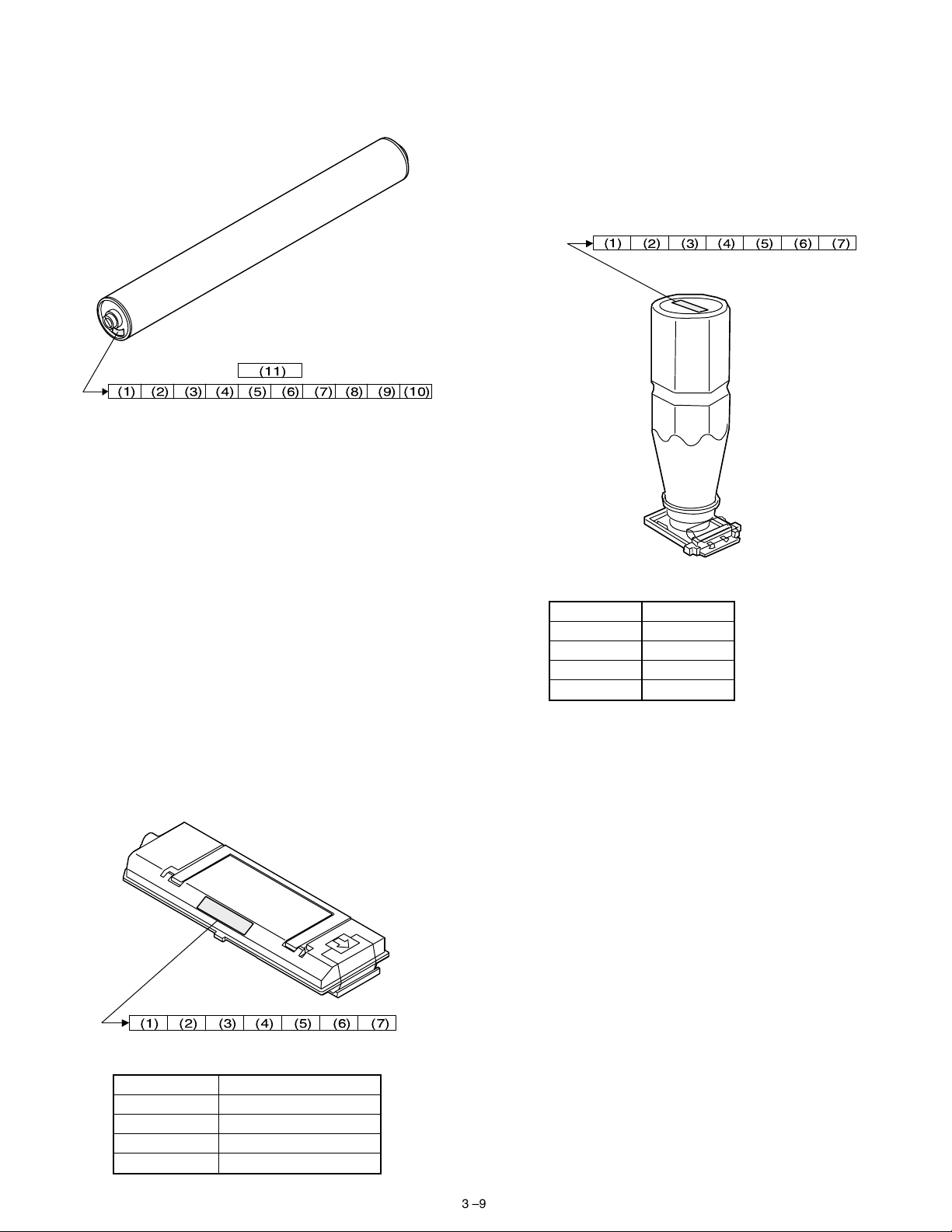
3. Photoconductor, developer, toner
A. Serial number identification
(1) Photoconductor
(11)
(1) (2) (3) (4) (5) (6) (7) (8) (9)
(1) Figure
Indicates the sensitivity of the photoconductor.
(2) (3) Alphabet
Indicates the model code. This machine’s code is PD (or PN
for the AR-C160 black.).
(4) Figure
Indicates the end digit of the production year.
(5) Figure or X, Y, Z
Indicates the production month. X= October, Y= November,
Z= December
(6) Figure
Indicates the production lot.
(7) Figure
Indicates the sub lot division.
(8) Figure or X, Y, Z
Indicates the packing month. X= October, Y= November, Z=
December
(9) (10) Figure
Indicates the packing date.
(11) Figure or alphabet
Indicates the product name of the drum.
NOTE: The shape of flange for the AR-C160 black OPC drum differs
from the others.
(2) Developer
(10)
(3) Figure, alphabet
Indicates the production month. X= October, Y= November,
Z= December
(4) (5) Figure
Indicates the production date.
(6) Figure
Indicates the end digit of the production year.
(7) Alphabet
Indicates the management code. (A to Z)
(3) Toner
(1) (2) (3) (4) (5) (6) (7)
(1) (2) Alphabet
Indicates the toner color as shown below:
Color Alphabet
Yellow RY
Magenta RM
Cyan RC
Black SK
(3) Figure, alphabet
Indicates the production month. X= October, Y= November,
Z= December
(4) (5) Figure
Indicates the production date.
(6) Figure
Indicates the end digit of the production year.
(7) Alphabet
Indicates the management code. (A to Z)
(1) (2) (3) (4) (5) (6) (7)
(1) (2) Alphabet
Indicates the developer color as shown below:
Color Alphabet
Yellow YR
Magenta MR
Cyan CR
Black KS (KT for the AR-C160)
3 – 9
Page 31

4. Paper
(1) Color print paper
The recommendable color print paper is shown below.
Use of the recommendable paper provides the best copy quality. The
standard paper follows it.
Kind Model Supplier Specification Note
Recommend
paper
Standard paper Necosa Necosa [11 × 8.5", 75g/m
OHP sheet
(Specified paper)
Hammermill
LASER PRINT
Neusiedler
Color Copy
(90g/m
HammermillDPHammermill [11 × 8.5", 75g/m
Igepa Igepa [A4, 80g/m
BG74.6 FOREX A4 size, 140g/m
Hammermill [11 × 8.5", 90g/m
Neusiedler [A4, 90g/m
2
)
[11 × 17", 90g/m
[A3, 90g/m
[11 × 17", 75g/m
[11 × 17", 75g/m
[A3, 80g/m
When paper of low white level is used, normal copy quality (color reproduction) may not be obtained.
For OHP sheet, be sure to use the specified one.
(2) Monochrome print paper
For monochrome print, the following specifications serve as the criteria of applicable or not.
(Values are under 20 ± 1°C, 65 ± 2%RH)
Item Standard paper Applicable paper
Weight 60 – 90g/m
Smoothness Front: ≥ 20s
Back : ≥ 20s
(BEEK method)
2
60 – 120g/m
Front: ≥ 20s
Back : ≥ 18s
(BEEK method)
Vesicularity ≥ 7s (BEEK method) Same as the left.
Untransparency ≥ 77% Same as the left.
Surface
resistance
10
1 × 10
– 5 × 10
(20 ± 1°C, 65 ± 2%RH)
Hardness Vertical: ≥ 17cm
10
Ωcm
≥ 5.0 × 10⁸Ωcm
(20 ± 1°C, 65 ± 2%RH)
Same as the left.
Horizontal: ≥ 13cm
(CLARK method)
Water content 4.5 % – 7.0% Same as the left.
Thickness 75µm – 110 µm Same as the left.
Dimensions Standard ± 1mm (
) Same as the left.
∗
(3) Print paper dimension specification
(∗) Standard dimensions are as follows:
B5 (182 ± 1 × 257 ± 1mm)
B6 (128 ± 1 × 182 ± 1mm)
A4 (210 ± 1 × 297 ± 1mm)
A5 (148 ± 1 × 210 ± 1mm)
A6 (105 ± 1 × 148 ± 1mm)
8.5" ± 5/128 × 14" ± 5/128 inch
8.5" ± 5/128 × 11" ± 5/128 inch
8.5" ± 5/128 × 8.5" ± 5/128 inch
8.5" ± 5/128 × 13" ± 5/128 inch
(Note)
(Paper which cannot be used)
The following paper cannot be used for printing.
Paper with coated surface
•
Paper with rough surface, or too smooth surface
•
Documents which are separated from a pasted book
•
Broken paper, folded paper, embossed paper, dry paper, wet pa-
•
per, curled paper
Paper with metal tab or clip
•
Paper with holes, cutout, or perforations
•
2
]
2
]
2
]
2
]
2
]
2
]
2
]
2
]
2
]
2
]
2
Made by
FOLEX
2
5. Environmental conditions
(1) Transit environment (sealed)
Max. change: Temperature 15°C/hour,
Relative humidity 15%RH/hour, without dew
Humidity
RH
90%
10%
-5˚C 40˚C
Temperature
Temperature (min)
Humidity
–5°C 10% 40°C 90% —
(min)
Temperature (mid)
Humidity
(mid)
Tempera-
ture (max)
(2) Storage environment (sealed)
Max. change: Temperature 15°C/hour,
Relative humidity 15%RH/hour, without dew
Humidity
RH
90%
10%
-5˚C40˚C
Temperature
Temperature (min)
Humidity
–5°C 10% 40°C 90% —
(min)
Temperature (mid)
Humidity
(mid)
Tempera-
ture (max)
(Unsealed condition)
Humidity
RH
30˚C, 80%
80%
20%
15˚C35˚C
Temperature
Temperature (min)
Humidity
15°C 20% 30°C 60% 35°C 90% —
(min)
Temperature (mid)
Humidity
(mid)
Tempera-
ture (max)
40˚C, 90%
Humidity
(max)
40˚C, 90%
Humidity
(max)
35˚C, 60%
Humidity
(max)
Period
Period
Period
3 – 10
Page 32

Page 33

[5] EXTERNAL VIEW AND INTERNAL STRUCTURE
Page 34

B. Internal parts
(1) Cross section
12 34 5 6 7 8 9
67
66
65
64
63
62
61
60
59
58
57
56
55
54
53
52
51
444546474849
50
43
10
11
12
13
14
15
76
16
74
75
72
71
69
17
18
20
19
21
22
23
24
25
26
27
28
29
30
31
32
33
34
35
36
37
39404142
38
70
73
77
68
No.
Name Function and operation
Parts
1 No. 2 mirror Sends the original image to No. 3 mirror.
2 No. 3 mirror Send the original image to the CCD.
3 Y-LSU unit Converts yellow components of image signals sent from the ICU PWB into laser
beams, and radiates the beams onto the OPC drum.
4 M-LSU unit Converts magenta components of image signals sent from the ICU PWB into laser
beams, and radiates the beams onto the OPC drum.
5 No. 1 mirror Sends the original image to No. 2 mirror.
6 Scanner lamp Radiates light to the CCD for scanning the original image.
7 CCD lens Reduces the original image (light) and project it to the CCD.
8 C-LSU unit Converts cyan components of image signals sent from the ICU PWB into laser
beams, and radiates the beams onto the OPC drum.
9 CCD PWB Reads the original image and converts it into electrical signals.
10 K-LSU unit Converts black components of image signals sent from the ICU PWB into laser
beams, and radiates the beams onto the OPC drum.
11 Developing roller (Y) Attaches toner on the OPC drum. (Y)
12 Developing roller (M) Attaches toner on the OPC drum. (M)
13 Developing roller (C) Attaches toner on the OPC drum. (C)
14 Developing roller (K) Attaches toner on the OPC drum. (K)
15 Upper resist roller Transports paper to the transfer section.
16 Lower resist roller Transports paper to the transfer section.
17 Paper transport roller 1 Transports paper to the transfer resist roller.
18 Idle roller Applies pressure to paper and the transport roller.
19 Idle roller Prevents against paper skew.
20 Paper transport roller 1 Transports paper to the transfer section (transfer resist roller).
21 Paper feed tray (No. 1 paper tray) Feeds paper to the paper transport section.
22 Separation roller (No. 1 paper tray) Separates paper and transport it to the paper transport section.
Note
5 – 4A
Page 35

No.
Name Function and operation
Parts
Note
23 Paper pickup roller (No. 1 paper tray) Sends paper to the paper feed roller.
24 Idle roller Applies pressure to paper and the transport roller.
25 Paper transport roller 2 Transports paper to the transport roller 1.
26 Paper feed roller (No. 2 paper roller) Feeds paper to the paper transport section.
27 Separation roller (No. 2 paper tray) Separates paper and prevents against double feed.
28 Paper pickup roller (No. 2 paper tray) Sends paper to the paper feed roller.
29 Idle roller Applies pressure to paper and the transport roller.
30 Paper transport roller 3 Transports paper to the transport roller 2.
31 Paper feed roller (No. 3 paper tray) Feeds paper to the paper transport section.
32 Separation roller (No. 3 paper tray) Separates paper and prevents against double feed.
33 Paper pickup roller (No. 3 paper tray) Feeds paper to the paper feed roller.
34 Idle roller Applies pressure to paper and the transport roller.
35 Paper transport roller 4 Transports paper to the transport roller 3.
36 Paper feed roller (No. 4 paper tray) Feeds paper to the paper transport section.
37 Separation roller (No. 4 paper tray) Separates paper and prevents against double feed.
38 Paper pickup roller (No. 4 paper tray) Sends paper to the paper feed roller.
39 Transfer roller (K) Applies a transfer voltage to the transfer belt.
40 OPC drum unit (K) Forms black latent electrostatic images.
41 Main charger unit (K) Charges the black OPC drum negatively.
42 OPC drum unit (C) Forms cyan latent electrostatic images.
43 Transfer roller (C) Applies a transfer voltage to the transfer belt.
44 Main charger unit (C) Charges the cyan OPC drum negatively.
45 OPC drum unit (M) Forms magenta latent electrostatic images.
46 Transfer roller (M) Applies a transfer voltage to the transfer belt.
47 Main charger unit (M) Charges the magenta OPC drum negatively.
48 OPC drum unit (Y) Forms yellow latent electrostatic images.
49 Transfer roller (Y) Applies a transfer voltage to the transfer belt.
50 Main charger unit (Y) Charges the yellow OPC drum negatively.
51 Transfer belt Transfers toner images on the OPC drum to paper.
52 Waste toner bottle Collects waste toner.
53 Oil tank Stores oil.
54 Lower heater lamp Heats the lower heat roller.
55 Lower heat roller Applies a pressure and heat to toner and fuses it to paper.
56 Lower separation pawl Separates paper mechanically from the lower heat roller.
57 Fusing transport roller Transports paper to the paper exit roller.
58 ADU gate Switches the paper route in the duplex mode.
59 Paper exit roller Discharges paper outside the machine.
60 Idle roller Applies pressure to paper and the paper exit roller.
61 Idle roller Applies pressure to paper and the transport roller.
62 Upper cleaning roller Cleans the fusing roller.
63 Upper heat roller Applies a pressure and heat to toner and fuses it to paper.
64 Upper heat lamp Heats the upper heat roller.
65 Oil roller Applies oil to the upper heat roller.
66 Oil blade Controls oil quantity on the oil roller to be even.
67 Separation pawl Separates paper from the transfer belt mechanically. Japan only
68 Waste toner bottle Collects waste toner from transfer belt.
69 Paper pickup roller Sends paper to the paper feed roller. Manual paper
feed section
70 Paper pickup solenoid Presses paper onto the paper pickup roller.
71 Manual paper feed roller Feeds paper to the paper transport section.
72 Manual paper feed clutch Transmits the paper feed drive motor power to the manual paper feed unit.
(Controls ON/OFF of the manual paper feed unit.)
73 Separation roller Separates paper to prevent against double feed.
74 Manual transport roller Applies a pressure to paper and the transport roller to give the transport roller
power to the paper.
75 Idle roller Applies a pressure to paper and the transport roller and gives a transport power of
the transport roller to the paper.
76 Resist roller cleaner Clean the resist roller. AR-C160 only
5 – 5A
Page 36

f. Transfer section
4
3
2
9
10
18
1
7
16
5
6
12
7
11
8
28
14
15
26
24
13
27
19
4
5 5 5
2
3
5
6 6 6
8
12
6
10
22
16
15
14
13
21
Parts
No.
Code
Signal
name
Name Type Function/Operation
1 Transfer unit Transfers toner from the OPC
drum to paper.
2 Transfer belt
separation pawl
3 BPSS BPSS Separation pawl
solenoid
4 Transfer belt
Separates paper from the
transfer belt mechanically.
Drives the separation
solenoid.
Drives the transfer belt.
drive roller
5 Transfer
discharge
Discharges electric charges
of the transfer belt.
electrode
6 Transfer roller Applies a transfer voltage to
the transfer belt.
7 Lift cam Transmits the transfer belt lift
motor power to the transfer
unit.
8 PCS PCS Image density
sensor
9 BLUM BLUM Transfer belt
Photo sensor
(Photo reflection)
Detects toner patch density in
image density correction.
Stepping motor Lifts the transfer belt unit.
motor
25
Active
condition
Analog input
23
20
28
Model Note
Japan only
Not equipped
(AR-C160)
4 pcs (Y, M, C,
K)
4 pcs (Y, M, C,
K)
Lifted up in
color print
mode, and lifted
down in
monochrome
mode.
5 – 6A
Page 37

Parts
No.
Code
10 CALS CALS Sensor switch
11 TC high voltage
Signal
name
Name Type Function/Operation
Selects the image density
solenoid
sensor.
Generates the high voltage
power PWB
for transfer.
12 Transfer belt Transfers toner images on
the OPC drum onto paper.
13 Waste toner tank Collects toner of toner patch
used in image density
correction.
14 Transfer belt
cleaning blade
Cleans toner of toner patch
used in image density
correction.
15 Transfer belt idle
roller
16 Transfer belt
cleaning pad
17 BLUD BLUD Transfer belt
position sensor
Photo sensor
(Photo
Applies a tension to the
transfer belt.
Cleans the back of the
transfer belt.
Detects that the transfer belt
is lifted up or down.
transmission)
18 BTM BTM Transfer belt
Stepping motor Drives the transfer belt.
drive motor
19 PSM PSM Resist roller
drive motor
20 HUD HUD Temperature
sensor
Stepping motor Drives the resist roller and
controls ON/OFF.
Detects humidity in the
machine.
21 PCU sub PWB Controls the image process
section.
22 Oil pump Supplies fusing oil to the
fusing roller.
23 PPD1 PPD1 Paper detector in
front of resist
roller
Photo sensor
(Photo
transmission)
Detects paper in front of the
resist roller.
24 Upper resist roller Transports paper to the
transfer section.
25 Lower resist roller Transports paper to the
transfer section.
26 BELTCH1 BELTCH1 Transfer belt
installation
detection switch
Micro switch Turns ON/OFF the +24V
power line from the DC main
power PWB to the PCU PWB.
(+24V)
27 BELTCH2 BELTCH2 Transfer belt
installation
detection switch
Micro switch Turns ON/OFF the +5V
power line from the DC main
power PWB to the PCU PWB.
(+5V)
28 Resist roller
Cleaning the resist roller AR-C160
cleaner
Active
Model Note
condition
Switches the
sensor angle
depending on
detection of
color toner
patch density or
black toner
patch density.
L when lifting
up H when
lifting down
Analog input Each correction
of image
process section
is made
according to
this sensor data.
L with paper
presence
This detector
signal serves as
the paper
transport timing
control signal to
the transfer
section.
The operation
timing is
controlled by
the resist roller
motor.
ON when the
transfer unit
operation is
allowed.
ON when the
transfer unit
operation is
allowed.
5 – 7A
Page 38

(8) PWB
(AR-C150/C250)
1
2
3
4
9
10
8
5
31
12
6
7
22
14
15
(AR-C160)
25
26
13
1
2
3
9
11
4
10
31
27
16
18
23
24
19
20
8
5
12
6
7
17
28
29
30
20
28
22
1719
2930
14
15
25
26
13
11
27
18
23
24
19
20
16
17
28
29
30
20
28
1719
2930
5 – 8A
Page 39

No.
Name Function/Operation
Parts
Note
1 Operation PWB L Outputs the key operation signals.
2 OP control PWB Controls the whole operation unit. (Displays information from the PCU PWB, and
sends operation information to the PCU PWB.)
3 Operation PWB R Outputs the key operation signals.
4 LCD back light inverter PWB Drives the LCD back light.
5 ICU-Main PWB Controls the ICU SCN PWB, ICU IMG PWB, and CCD PWB. Converts digital
image data into video signals and sends them to the scanner (writing) unit.
6 ICU-SCN PWB Performs correction of images outputted from the CCD.
7 ICU-IMG PWB Performs image processes such as area separation, color correction, black
generation, gamma correction, and filter process.
8 CPT PWB Recognizes the bank note patterns.
9 Original size sensor PWB
Detects the original size.
(Light reception)
10 Original size sensor (Light
Outputs light to detect the original size.
emitting)
11 CCD power PWB Outputs the CCD PWB paper power.
12 Scanner motor PWB Scanner motor control PWB. Controls the
scanner motor.
13 PCU sub PWB Controls the image process section.
14 High voltage power PWB
Generates the high voltage for main charger and the developing bias voltage.
(MC/DV)
15 Main charger interface PWB Interfaces the main charger power.
16 OPC drum motor control/Signal
interface PWB
Controls (drives) the OPC drum motor. (AR-C150/C250/C160)
Signals are interfaced. (AR-C160)
17 Scanner lamp control PWB Controls the scanner lamp
18 Humidity sensor PWB Detects humidity in the machine. Each correction of
image process
section is made by
this sensor data.
19 PCU PWB (A) Controls the engine section.
20 PCU PWB (B) Controls the engine section.
21 Paper tray lift unit control PWB Controls the paper tray lift unit. Provided in each
paper tray lift unit.
22 Discharge lamp PWB unit Discharges electric charges on the OPC drum.
23 IFD PWB Equipped with No. 1/2 paper tray paper exit detectors and the right upper door
open/close detector.
24 PFD PWB unit Equipped with No. 3/4 paper tray paper exit detectors and the right lower door
open/close detector.
25 Process control PWB Interfaces signals between the developing unit, OPC drum unit, the high voltage
PWB, and the PCU PWB.
26 Fusing control PWB (AC sub
Interfaces the heater lamp drive control, sensor, detector signals.
PWB)
27 High voltage power PWB (TC) Generates the transfer voltage.
28 DC main power PWB
Generates the voltage used by the other units than the operation unit.
(AR-C100/C150/C250)
DC power PWB (AR-C160)
29 DC sub power PWB
(AR-C150/C250)
Power control PWB (AR-C160)
Generates the voltage for the operation unit (AR-C150/C250)
Controls powers of 24V, 5V and 3.3V in the sleep mode, the preheat mode, and
the normal mode. (AR-C160)
30 AC power PWB Controls the primary side power (AC power).
31 CCD PWB Converts original images (light) into electrical signals.
5 – 9A
Page 40

(9) Fuses, thermostat
(AR-C150/C250)
1
16
15
14
13
12
11
10
2
4
3
5
17
6
7
No.
Code Name Type Spec Function/Operation
1 F1 Scanner motor
power fuse
2 HLTSU Upper heat roller
thermostat
3 HLTSD Lower heat roller
thermostat
4 F101 OPC drum motor
power fuse
5 F701 Scanner lamp
power fuse
6 F712 DC sub power
26V power fuse
7 F711 DC sub power
primary size fuse
8 F102 AC main power
primary side fuse
AC main power
primary side fuse
AC main power
primary side fuse
9 F101 AC main power
primary side fuse
AC main power
primary side fuse
AC main power
primary side fuse
10 F702 DC main power
+ 5V fuse
8
Parts
Normal fuse Protects the scanner motor and its control
circuit from an overcurrent.
Thermostat Cuts conduction to the heater lamp when the
9
Note
Scanner motor
control PWB
Fusing unit
temperature rises abnormally.
Thermostat Cuts conduction to the heater lamp when the
Fusing unit
temperature rises abnormally.
Normal fuse Protects the OPC drum motor and its control
circuit from an overcurrent.
OPC drum motor
control PWB
Normal fuse 250V 4A Protects the scanner lamp from an overcurrent. Scanner lamp
control PWB
Normal fuse 250V 1A Protects the PCC main PWB and the operation
control PWB form an overcurrent.
Normal fuse 250V 3.15A Protects the DC sub power primary side from
an overcurrent.
Normal fuse 125V 20A Protect the AC main power primary side from
DC sub power
PWB
DC sub power
PWB
Japan
an overcurrent.
Normal fuse 250V 15A Protect the AC main power primary side from
100V series
an overcurrent.
Normal fuse 240V 10A Protect the AC main power primary side from
200V series
an overcurrent.
Normal fuse 125V 20A Protect the AC main power primary side from
Japan
an overcurrent.
Normal fuse 250V 15A Protect the AC main power primary side from
100V series
an overcurrent.
Normal fuse 240V 10A Protect the AC main power primary side from
200V series
an overcurrent.
Normal fuse 125V 6.3A Protects the ICU PWB from an overcurrent. 100V series
5 – 10A
Page 41

No.
Code Name Type Spec Function/Operation
11 F703 DC main power
+ 5V fuse
12 F704 DC main power
+ 24V
DC main power
+ 24V
13 F705 DC main power
+ 24V
DC main power
+ 24V
14 F706 DC main power
+ 24V
DC main power
+ 24V
15 F707 DC main power
+ 24V
DC main power
+ 24V
16 F708 DC main power
+ 24V
DC main power
+ 24V
17 Scanner lamp
temperature fuse
(AR-C160)
Parts
Normal fuse 125V 6.3A Protects the PCU main PWB, LSU, and CCD
power PWB from an overcurrent.
Normal fuse 125V 6.3A Protects the PCU main PWB from an
overcurrent.
Normal fuse 250V 6.3A Protects the PCU main PWB and the high
voltage PWB (MC/DN) from an overcurrent.
Normal fuse 125V 6.3A Protects the PCU main PWB and the high
voltage PWB (MC/DN) from an overcurrent.
Normal fuse 250V 6.3A Protects the PCU main PWB from an
overcurrent.
Normal fuse 125V 6.3A Protects the scanner motor control PWB, LSU,
and CCD power PWB from an overcurrent.
Normal fuse 250V 6.3A Protects the scanner motor control PWB, LSU,
and CCD power PWB from an overcurrent.
Normal fuse 125V 6.3A Protects the process control PWB, the OPC
drum control PWB, and the developing motor
(color) from an overcurrent.
Normal fuse 250V 6.3A Protects the process control PWB, the OPC
drum control PWB, and the developing motor
(color) from an overcurrent.
Normal fuse 125V 6.3A Protects the PCU main PWB, RADF, the sorter,
the large capacity paper tray, the OPC drum
control PWB, and the developing motor (color)
from an overcurrent.
Normal fuse 250V 6.3A Protects the PCU main PWB, RADF, the sorter,
the large capacity paper tray, the OPC drum
control PWB, and the developing motor (color)
from an overcurrent.
Temperature
fuse
104°C 250V
10A
Cuts conduction to the scanner lamp when the
temperature rises abnormally.
Note
100V series
100V series
200V series
100V series
200V series
100V series
200V series
100V series
200V series
100V series
200V series
100V
9
10
11
2
1
3
5
12
200V
9
10
11
6
8
7
5 – 11A
Page 42

No.
Code Name Type Spec Function/Operation
1 F1 Scanner motor
power fuse
2 HLTSU Upper heat roller
thermostat
3 HLTSD Lower heat roller
thermostat
4 F101 OPC drum motor
power fuse
5 F701 Scanner lamp
power fuse
6/7 F102/F101 AC main power
primary side fuse
AC main power
primary side fuse
AC main power
primary side fuse
8 F1 DC power
primary side fuse
9 F2 DC main power
+ 24V
DC main power
+ 24V
10 F3 DC main power
+ 24V
DC main power
+ 24V
11 F4 DC main power
+ 24V
DC main power
+ 24V
12 Scanner lamp
temperature fuse
(11) Power source
(AR-C150/C250)
Parts
Normal fuse Protects the scanner motor and its control
circuit from an overcurrent.
Thermostat Cuts conduction to the heater lamp when the
Note
Scanner motor
control PWB
Fusing unit
temperature rises abnormally.
Thermostat Cuts conduction to the heater lamp when the
Fusing unit
temperature rises abnormally.
Normal fuse Protects the OPC drum motor and its control
circuit from an overcurrent.
OPC drum motor
control PWB
Normal fuse 250V 4A Protects the scanner lamp from an overcurrent. Scanner lamp
control PWB
Normal fuse 125V 20A Protect the AC main power primary side from
Japan
an overcurrent.
Normal fuse 250V 15A Protect the AC main power primary side from
100V series
an overcurrent.
Normal fuse 240V 10A Protect the AC main power primary side from
200V series
an overcurrent.
Normal fuse 250V 4.0A Protect the DC power primary side from an
200V series
overcurrent.
Normal fuse 125V 4.0A Overcurrent protection of the LSU, the OPC
100V series
drum motor, the RADF, the finisher, the PCU
Normal fuse 250V 6.3A 200V series
MAIN PWB, the paper feed/transport section
motors
Normal fuse 125V 4.0A Overcurrent protection of the PCU SUB PWB,
100V series
the transfer belt section motor, the fusing
Normal fuse 250V 6.3A 200V series
motor, the developing motor (color), the CD
power PWB, and the high voltage (TC) PWB
Normal fuse 125V 4.0A Overcurrent protection of the developing motor
100V series
(black), the high voltage (MC, DV) PWB, the
Normal fuse 250V 6.3A 200V series
LCC, the scanner motor, the operation PWB,
the ADU, and the printer controller
Temperature
fuse
104°C 250V
10A
Cuts conduction to the scanner lamp when the
temperature rises abnormally.
1
3
2
7
4
5
6
5 – 12A
Page 43

(AR-C160)
No.
1
3
2
Parts
Name Function/Operation Spec
7
4
5
6
1 CCD power PWB Outputs the CCD PWB power.
2 High voltage power
Generates the transfer voltage.
PWB (TC)
3 Fusing control PWB
(AC sub PWB)
Interfaces the heater lamp drive control, the sensor, and the
detector signals.
4 DC main power PWB Generates a voltage used by the other unit than the operation unit.
5 Dc sub power PWB
(AR-C150/C250)
Power control PWB
Generates a vlotage for the operation unit (AR-C150/C250)
Controls powers of 24V, 5V and 3.3V in the sleep mode, the
preheat mode, and the normal mode. (AR-C160)
(AR-C160)
6 AC main power PWB Controls the power (AC power) on the primary side.
7 High voltage power PB
(MC/DV)
Generates the high voltage for the main charger and the developing
bias voltage.
(12) Adjustment volumes
(AR-C150/C250)
Note
2
3
4
1
5 – 13A
Page 44

No.
Code Name Function/Operation
Parts
Note
1 VR1 HLV power voltage adjustment volume Adjusts the HLV voltage. DC sub power PWB
2 VR704 +3.4V power voltage adjustment volume Adjusts the +3.4V power voltage. DC main power PWB
3 VR703 +5V power voltage adjustment volume Adjusts the +5Vpower voltage. DC main power PWB
4 VR702 +24V power voltage adjustment volume Adjusts the +24V power voltage. DC main power PWB
(AR-C160)
200V
3
2
Parts
Note
No.
100V
1
Code Name Function/Operation
1 RV2 (100V series) +3.4V power voltage adjustment volume Adjusts the +3.4V power voltage. DC power PWB
2 VR201 (200V series) +5V power voltage adjustment volume Adjusts the +5Vpower voltage. (200V series) DC power PWB
3 VR301 (200V series) +3.4V power voltage adjustment volume Adjusts the +3.4V power voltage. DC power PWB
5 – 14A
Page 45

[6] MACHINE OPERATIONS
1. Operation mode
This machine has the following operation modes.
Mode Contents
Copy mode Basic operation mode Used to select paper and set the copy magnification ratio and copy density, etc.
Special function mode Used to edit images and adjust color.
Duplex copy mode Used to make various setups of duplex copy mode.
Finishing mode Used to make various setups related to the sorter.
Job program mode Used to preset the copy operation conditions.
User setup mode Used to make setup of the specifications according to the user’s needs.
Operation guidance mode Help menu (Displays the operational descriptions on copying.)
Printer mode Uses the print server (option) to perform as a printer.
Power save mode Pre-heat mode Used to lower the fusing temperature, saving the power consumption.
Sleep mode Used to stop the sections except for the control PWB section.
Simulation mode Used in servicing to set, adjust, and check operations.
2. Operation menu
This machine has the following operation menus.
These operation menus differ depending on installation of options and the configurations.
AR-C150/C250/C160 Operation Menus
Level 1 Level 2 Level 3 Level 4 Level 5
Basic menu Paper
5-way paper feed model (with an option tray installed)
Tra y 1
Tray 2
Tra y 3
Tra y 4
Manual paper feed Normal paper
BY-PASS:
(AR-C150)
Paper size/remaining quantity display
4-way paper feed model (Standard model)
With the duplex unit installed
Tra y 1
Tray 2
Tra y 3
Manual paper feed Normal paper
BY-PASS:
(AR-C150)
Paper size/remaining quantity display
6-way paper feed model (With the option tray/LCC installed)
Tra y 1
Tray 2
Tra y 3
Tra y 4
Tray 5 (LCC)
BY-PASS:
(AR-C150)
Paper size/remaining quantity display
5-way paper feed model (with the option tray/LCC installed)
With the duplex unit installed
Tra y 1
Tray 2
Tra y 3
Tray 4 (LCC)
BY-PASS:
(AR-C150)
Paper size/remaining quantity display
Thick paper
OHP
[16 – 28 lbs]
[28+ – 55 lbs]
[60 – 105g/m²]
[106 – 200g/m²]
[TRANSPARENCY]
Thick paper
OHP
[16 – 28 lbs]
[28+ – 55 lbs]
[60 – 105g/m²]
[106 – 200g/m²]
[TRANSPARENCY]
[16 – 28 lbs]
[28+ – 55 lbs]
[60 – 105g/m²]
[106 – 200g/m²]
[TRANSPARENCY]
[16 – 28 lbs]
[28+ – 55 lbs]
[60 – 105g/m²]
[106 – 200g/m²]
[TRANSPARENCY]
BY-PASS:
(AR-C250)
BY-PASS:
(AR-C250)
BY-PASS:
(AR-C250)
BY-PASS:
(AR-C250)
[16 – 28 lbs]
[28+ – 35 lbs]
[35+ – 55 lbs]
[60 – 105g/m²]
[106 – 130/m²]
[131 – 200g/m²]
[TRANSPARENCY]
[16 – 28 lbs]
[28+ – 35 lbs]
[35+ – 55 lbs]
[60 – 105g/m²]
[106 – 130/m²]
[131 – 200g/m²]
[TRANSPARENCY]
[16 – 28 lbs]
[28+ – 35 lbs]
[35+ – 55 lbs]
[60 – 105g/m²]
[106 – 130/m²]
[131 – 200g/m²]
[TRANSPARENCY]
[16 – 28 lbs]
[28+ – 35 lbs]
[35+ – 55 lbs]
[60 – 105g/m²]
[106 – 130/m²]
[131 – 200g/m²]
[TRANSPARENCY]
BY-PASS:
(AR-C160)
BY-PASS:
(AR-C160)
BY-PASS:
(AR-C160)
BY-PASS:
(AR-C160)
[16 – 28 lbs]
[28+ – 35 lbs]
[35+ – 75 lbs]
[60 – 105g/m²]
[106 – 130/m²]
[131 – 280g/m²]
[TRANSPARENCY]
[16 – 28 lbs]
[28+ – 35 lbs]
[35+ – 75 lbs]
[60 – 105g/m²]
[106 – 130/m²]
[131 – 280g/m²]
[TRANSPARENCY]
[16 – 28 lbs]
[28+ – 35 lbs]
[35+ – 75 lbs]
[60 – 105g/m²]
[106 – 130/m²]
[131 – 280g/m²]
[TRANSPARENCY]
[16 – 28 lbs]
[28+ – 35 lbs]
[35+ – 75 lbs]
[60 – 105g/m²]
[106 – 130/m²]
[131 – 280g/m²]
[TRANSPARENCY]
Japan
EX Japan
Japan
EX Japan
EX Japan
EX Japan
6 – 1
Page 46

Magnification ratio
Copy density
Normal mode
Color enhancement
mode
AR-C160
Magnification ratio
100% (Normal)
Zoom up
Zoom down
86%(AB)/77% (Inch)
81% (AB)/64% (Inch)
70%(AB)
115%(AB)/121%(Inch)
122%(AB)/129%(Inch)
141%(AB)/
200%(AB/Inch)
400%(AB/Inch)
Optional % 1 (Displayed when registered)
Optional % 2 (Displayed when registered)
Optional % 3 (Displayed when registered)
Optional % 4 (Displayed when registered)
Auto selection of magnification ratio
Independent zooming of vertical/horizontal magnification ratios
Auto
Manual
Auto
Manual
Auto
Manual
Auto
Manual
AR-C150
AR-C150
AR-C250
AR-C250
AR-C160
AR-C160
AR-C160
AR-C160
Setup pallet of independent zooming of
vertical/horizontal magnification ratios
Horizontal (X) shaft selection
(Magnification ratio)
Vertical (Y) shaft selection
(Magnification ratio)
Zoom up
Zoom down
100%(Normal)/77%(Inch)
70%(AB)/77%(Inch)
64%(AB)/64%(Inch)
50%(AB)/50%(Inch)
141%(AB)/129%(Inch)
200%(AB)/200%(Inch)
400%(AB)/40%(Inch)
Text/Photo (Default)
Tex t
Photo Dark/Light
Printed Photo Dark/Light
Map Dark/Light
Text/Photo (Default) Dark/Light
Text Dark/Light
Text/Printed photo (Default)
Text/Photo
Tex t
Photo Dark/Light
Printed Photo Dark/Light
Map Dark/Light
Text/Printed photo (Default) Dark/Light
Text Dark/Light
Text/Photo Dark/Light
Copy of Copy Text/Printed photo
Printed photo
Tex t
Text/Printed photo (Default)
Text/Photo
Tex t
Photo Dark/Light
Printed Photo Dark/Light
Map Dark/Light
Text/Printed photo (Default) Dark/Light
Text Dark/Light
Text/Photo Dark/Light
Copy of Copy Text/Printed photo
Printed photo
Tex t
Text/Printed photo (Default)
Text/Photo
Tex t
Photo Dark/Light
Printed Photo Dark/Light
Map Dark/Light
Text/Printed photo (Default) Dark/Light
Text Dark/Light
Text/Photo Dark/Light
Dark/Light
Dark/Light
Dark/Light
Dark/Light
Dark/Light
Dark/Light
6 – 2
Page 47

Level 1 Level 2 Level 3 Level 4 Level 5
Special functions
Duplex copy
Output
Binding margin Binding position (Left)
1 set 2 copy [ON/OFF] Front/Binding margin DOWN key
Centering [ON/OFF]
Erase
OHP cover paper insertion copy [ON/OFF]
Cover insertion
(Displayed only when the RADF is installed)
Color adjustment RGB Red
Image edit Single color
Non-RADF mode
S S
S D (Even number)
RADF mode
S S
S D (Even number)
S D (Odd number)
D S
D D
Document count
20-bin staple sorter
Non sort
Sort
Group
Staple sort
Finisher
Non sort
Group
Sort (Only available in the printer mode)
Staple sort (Only available in the printer mode)
Off set (Copy mode)
Non off set
Binding position (Right)
Front/Binding margin UP key
Back/Binding margin UP key
Back/Binding margin DOWN key
Erase width UP key
Erase width DOWN key
Center widht key
Center widht key
Cover only
Back cover only
Cover + Back cover
Cover copy (Yes/No)
Sharpness Soft
Background erase Level adjustment
Brightness/Sharpness/Contrast Brightness
Color balance C, M, Y, BK
Negative-positive conversion [ON/OFF]
Mirror image [ON/OFF]
Photo repeat Repeat size selection (Japan)
A4 wide copy [ON/OFF]
Enlargement continuous copy
Extra size (AR-C250/C160)
Green
Blue
Sharpness
Sharpness
Contrast
1 Red
2 Blue
3 Green
4 Orange
5 Purple
6 Brown
Up to E/L version/A6 (148 105)
A4 (Paper): 4-surface print
A3 (Paper): 8-surface print
A4 (Paper) : 8-surface print
70 100mm
A3 (Paper): 16-surface print
65 70mm
A4 (Paper): 12-surface print
A3 (Paper): 24-surface print
Panorama
A4 (Paper): 2-surface print
A3 (Paper): 4-surface print
Repeat size selection (Inch series)
Up to 3 5"
8.5 11 (Paper): 4-surface print
11 17 (Paper): 8-surface print
Up to 2 1/2 4"
8.5 11 : 8-surface print
11 17 : 16-surface print
Up to 2 1/2 2 1/2"
8.5 11 : 12-surface print
11 17 : 24-surface print
Up to 5 7
11 17 (Paper): 4-surface print
Repeat size selection (AB series)
90 130mm
A4 (Paper): 4-surface print
A3 (Paper): 8-surface print
70 100mm
A4 (Paper): 8-surface print
A3 (Paper): 16-surface print
65 70mm
A4 (Paper): 12-surface print
A3 (Paper): 24-surface print
100 150mm
A3 (Paper): 4-surface print
Japan
Enlargement size Document size selection
A2 A5/A4/A3
A1 A5/A4/A3
A0 A4/A3
A0 2 A3
B3 B5/B4
B2 B5/B4
B1 B5/B4
B0 B4
AB series (A size only)
A2 A5/A4/A3
A1 A5/A4/A3
A0 A4/A3
A0 2 A3
Inch series
22 17 8.5 11/8.5 14/11 17
22 34 8.5 11/8.5 14/11 17
34 44 8.5 11/8.5 14/11 17
44 68 11 17
Original size setting (Input size value)
Paper size setting for BY-PASS
(Input size value)
6 – 3
Page 48

Level 1 Level 2 Level 3 Level 4 Level 5
Job program
Program 1
Program 2
Program 3
Program 4
Program 5
Program 6
Program 7
Program 8
Program 9
Registration/Erase
Program selection
Program 1
Program 2
Program 3
Program 4
Program 5
Program 6
Program 7
Program 8
Program 9
User setup
Operation
guidance
Toner supply (The menu display and "Operation Guidance"/"Toner supply" key are displayed only when toner concentration is decreased.)
Toner empty
Waste toner full (When the information key is pressed when in waste toner full, the waste toner collection paper replacement guidance is displayed.)
Printer mode
Operation display brightness adjustment
Key operator program Dept. management Dept counter setup
Function setup Key operator code change
Timer setup
User auto calibration
Inhibition setup Key touch alarm inhibition
Total copy quantity display
Program list print
Duplex copy
Output
Document feed unit
Paper
Magnification ratio
Program
Interruption
Binding margin
1 set 2 copy
Centering
Cover insertion
OHP cover insertion
Color adjustment
Single color
Negative/Positive
Mirror image
Photo repeat
A3 wide copy
Enlargement continuous copy
Display contrast
Extra size (AR-C250/C160)
(When the information key is pressed when in toner empty, the toner supply guidance is displayed.)
OFFLINE
ONLINE
Displayed only when the ADU is installed.
Displayed only when the sorter or finisher is installed.
Displayed only when the RADF is installed.
Displayed only when the RADF is installed.
Printer setup
Copy quantity total
Amount total
Total quantity/amount erase
Dept number setup
Copy unit price setup
Limitation of copy quantity
Warning for erroneous input of dept number
Auto copy mode copy density adjustment
Toner save mode setup (Black/White)
Program magnification ratio setup
Copy quantity upper limit setup
Binding margin standard value setup
Edge erase width standard value setup
Copy mode standard state setup
Color balance Color balance test copy
Paper feed tray paper size setup
Operation inhibition mode setup
Stream feeding mode setup
Staple sorter bin paper exit quantity limitation cancel
Transfer belt position setup (Color/B & W)
Sleep mode setup
Auto clear time setup
Pre-heat mode setup
Message display time setup
Paper auto select inhibition
Tray auto select inhibition
Manual feed tray inhibition in duplex copy
Registered copy condition rewrite inhibition
Document feed unit use inhibition
Duplex copy inhibition
Staple inhibition
Cover mode inhibition
Copy inhibition in warning of size/direction
PC Modem access inhibition
Sleep mode inhibition
Black/white copy pre-scan inhibition
Color copy inhibition
Copy (Color)
Copy (Black/white)
Duplex
Document feed unit
Stapler
Self print (Color)
Self print (Black/white)
Printer (Color)
Printer (Black/white)
Displayed in Japan/ Outside UK
Input size value (AR-C250/C160)
Displayed only when the RADF is installed
Displayed only when the sorter is installed
Use SIM 26-53 to set Enable/Disable
of this function.
Displayed only when the ADU is installed
Displayed only when the RADF is installed
Displayed only when the ADU is installed
Displayed only when the sorter is installed
Displayed only when the RADF is installed
Only in Japan
No display
6 – 4
Page 49

3. Pre-heat mode and sleep mode
operations
A. Operation timing
This machine has a pre-heat mode and a sleep mode to save the
power consumption when copying (printing) is not performed.
The shift timing to the pre-heat mode and the sleep mode can be set
with the user program with the non-operating state as the start point.
The timing of the two modes can be separately set. It is possible to
shift from the normal mode directly to the sleep mode without passing
through the pre-heat mode.
Operation timing in the pre-heat mode and the sleep mode
Copy (print) operation
(Pre-heat mode cancel conditions)
In the following cases, the pre-heat mode is canceled.
Operation
section
Auditor section Card insertion (Only in the
Original size
sensor section
RADF section RADF original size change
Paper tray
section
Finishing
Copy Copying
Self print
Printer control Printer operation
Scanner
(reading)
(Sleep mode cancel condition)
In the following cases, the sleep mode is canceled.
Self print
Printer control Printer operation
Scanner
(reading)
Stop
Tp (Pre-heat
mode timer)
Tp and Ts are set by the user program.
Timer Set time
TP 10 - 240min
Ts
10 - 240min
Control section Phenomenon NOTE
Key input other than 10-key
(Including Key ON)
card counter mode) (Japan
only)
Coin insertion (Only in the
coin vendor mode) (Japan
only)
Original size change
(Including Original Empty
→ Presence, Presence →
Empty)
(Including Original Empty
→ Presence, Presence →
Empty)
Scanner operation
Copy Copying NOTE
Scanner operation
Pre-heat mode
Sleep mode
Ts (Sleep mode timer)
(Sleep mode shift timing extending condition)
When the non-operation of copying and printing continues and the following case occurs within 10 min of entering the sleep mode, set the
sleep mode timer to 10 min again, and extend the shift timing to the
sleep mode.
Control section Phenomenon NOTE
Operation
section
Auditor section Card insertion (Only in the
Original size
detection
(Original size
sensor section)
RADF section RADF original size change
Paper tray
section
Finishing (sorter) Staple execution, (Front
Copy Copying
Self print Self printing
Printer control Printer operation
Scanner
(reading)
Key input other than 10-key
(Including Key ON)
card counter mode) (Japan
only)
Coin insertion (Only in the
coin vendor mode) (Japan
only)
Original size change
(Including Original Empty
→ Presence, Presence →
Empty)
(Including Original Empty
→ Presence, Presence →
Empty)
Paper tray attachment/
detachment detection,
Paper tray lift operation
take-up execution)
Scanner operation
B. Pre-heat mode and sleep mode operations
(1) Control unit operations in the pre-heat mode and the
sleep mode
a. Operation (operation panel) section
Mode Operation NOTE
Sleep LCD display Does not display.
Pre-heat
mode
Normal
LED lights
up.
Key Printer/Copy key:
Original
detection
Card reader Does not operate. Japan only
All load operations possible
Printer/Copy : Light
up.
Start, interruption,
data, online: Does
not light up.
Valid
Other keys: Invalid
Original size
sensor: Does not
operate.
Original cover
open/close
detection: Does
not operate
6 – 5
Page 50

b.PCU PWB
Mode Operates. NOTE
Sleep Does not operate.
Preheat Refer to "d. Signals controlled by
Normal Operates.
c.ICU PWB
Mode Operates. NOTE
Sleep Does not operate.
Low power
Normal Operates.
(Signals controlled by the PCU PWB in the pre-heat mode)
Section Signal name Content
Manual
paper feed
Paper feed
tray
Paper
transport
the PCU PWB in the pre-heat
mode".
MPWS Manual feed width
detection
MPLD1 Manual feed
MPLD2 Manual feed
MTOP1 Manual feed tray
MTOP2 Manual feed tray
MPED Manual feed
C
∗
SS1 Paper size
∗
SS2 Paper size
C
∗
SS3 Paper size
C
∗
C
SS4 Paper size
∗
PED
∗
LUD
∗
PD1 Paper remaining
C
LUM_ENB
∗
PFD
PPD1 Paper detection in
POD Machine paper
PODF Finisher paper exit
PFM Paper feed motor
TRC Transport clutch
MPFS Manual paper
MPFC Manual paper
∗
CPFS
∗
CPFC
RRM_START RR motor
length detection
length detection
pull-out detection
pull-out detection
paper empty
detection
detection
detection
detection
detection
Paper empty
detection
Paper upper limit
detection
quantity detection
1
∗
Paper tray lift-up
motor
Cassette paper
feed detection
front of RR roller
exit detection
detection
feed solenoid
feed clutch
Cassette paper
feed solenoid
Cassette paper
feed clutch
Operation in the
pre-heat mode
Does not
operate.
Does not
operate.
Does not
operate.
Section Signal name Content
Developing PRD_AN? Toner
concentration
detection
Fusing HLPR HL power relay ON
Waste
toner
Image
process
Coin
vendor
(Japan
only)
Scanner
(reading)
Copy lamp CL Scanner lamp Does not
Fan CFM Scanner (reading)
Others DSWF Front door open
TBBOX Waste toner bottle
TFD Waste toner full
DMENB All OPC drum
DVKM Developing motor
DVCM Developing motor
HPCH Toner hopper
PRD_ANRTH Image process
CV_COPY B/W copy allow
CV_CLCOPY Color copy allow
CV_COUNT Count signal Does not
CV_START Copy start signal
CV_COLOR Color signal
CV_SIZE0 Size signal 0
CV_SIZE1 Size signal 1
CV_SIZE2 Size signal 2
CV_SIZE3 Size signal 3
MHPS Mirror home
SMENB Scanner (writing)
VFPWM Fusing
LSUPWM LSU cooling fan
OZFM Ozone exhaust
DDSW Paper exit door
RDSWU Paper fed upper
RDSWD Paper feed lower
PSPR Main power relay OFF
MCLKA Paper tray lift
MCLKB
DHPR Dehumidifier
installation
detection
detection
drive motor
(Black)
(Color)
installation
detection
temperature
detection
signal
signal
position detection
motor
cooling fan
exhaust/cooling
fan
(LSUFM)
fan
detection
open detection
door open
detection
door open
detection
motor/Toner motor
heater power relay
Operation in the
pre-heat mode
Does not
operate.
Does not
operate.
Does not
operate.
❍
(No Money
insertion →
Detection ;
pre-heat mode
canceled)
operate.
Does not
operate.
operate.
Does not
operate.
Operates. (Only
the fusing
exhaust fan is
operable.)
Does not
operate.
Does not
operate.
Does not
operate.
Operates.
6 – 6
Page 51

d. Communication in the pre-heat mode
Section Signal name Content
PCU SUB
PWB
TXD_SUB PCU SUB data
send
RXD_SUB PCU SUB data
receive
Operation in the
pre-heat mode
Operates.
LCC TXD_LCC LCC data send Does not
RIC I/F TXD_RIC RIC data send Does not
BELTCH Transfer belt
pull-out detection
ADU TXD_ADU ADU data send Does not
RXD_ADU ADU data receive
RES_ADU ADU reset
operate.
ICU PWB ICU_RXD ICU data receive Does not
ADU_CH ADU pull-out
detection
RADF TXD_RADF RADF data send Operates.
RXD_RADF RADF data receive
Operation
unit
RES_RADF RADF reset
Sorter RES_SOT SOT reset Operates.
(2) Fusing section operation in the pre-heat mode and the sleep mode
(AR-C100/C150)
Ready
condition
Copy/Print
mode
Pre-heat
mode
Sleep
mode
Ready condition control temperature (HL1) Upper heat roller 187 187 187 177 177 187 187 187 187
Ready condition control temperature (HL2) Lower heat roller 142 142 142 132 132 142 142 142 142
Normal mode control temperature (HL1) Upper heat roller 180 180 180 170 170 180 180 180 180
Normal mode control temperature (HL2) Lower heat roller 135 135 135 125 125 135 135 135 135
Thick paper mode control temperature
(HL1)
Thick paper mode control temperature
(HL2)
OHP mode control temperature (HL1) Upper heat roller
OHP mode control temperature (HL2) Lower heat roller
Energy saving mode control temperature
(HL1)
Control temperature when resetting from
pre-heat to B/W (HL1)
HL1 Upper heat roller OFF OFF OFF OFF OFF OFF OFF OFF OFF
HL2 Lower heat roller OFF OFF OFF OFF OFF OFF OFF OFF OFF
(AR-C250/C160)
Ready
condition
Copy/Print
mode
Pre-heat
mode
Sleep
mode
Ready condition control temperature (HL1) Upper heat roller 177 177 177 177 177 177 177 177 177
Ready condition control temperature (HL2) Lower heat roller
Normal mode control temperature (HL1) Upper heat roller 170 170 170 170 170 170 170 170 170
Normal mode control temperature (HL2) Lower heat roller
Thick paper mode 1 control temperature
(HL1)
Thick paper mode 1 control temperature
(HL2)
Thick paper mode 2 control temperature
(HL1)
Thick paper mode 2 control temperature
(HL2)
OHP mode control temperature (HL1) Upper heat roller 180 180 180 180 180 180 180 180 180
OHP mode control temperature (HL2) Lower heat roller 175 175 175 175 175 175 175 175 175
Energy saving mode control temperature
(HL1)
Control temperature when resetting from
pre-heat to B/W (HL1)
HL1 Upper heat roller OFF OFF OFF OFF OFF OFF OFF OFF OFF
HL2 Lower heat roller OFF OFF OFF OFF OFF OFF OFF OFF OFF
Mode
Upper heat roller
Lower heat roller
Upper heat roller
Upper heat roller
Mode
Upper heat roller
Lower heat roller
Upper heat roller
Lower heat roller
Upper heat roller 136
Upper heat roller 148
U.S.A Canada Inch Japan AB_B Europe U.K Aus. AB_A
200 200 200 200 200 200 200 200 200
155 155 155 155 155 155 155 155 155
180 180 180 180 180 180 180 180 180
175 175 175 175 175 175 175 175 175
140 140 140
155 155 155
U.S.A Canada Inch Japan AB_B Europe U.K Aus. AB_A
132 132 132
125 125 125
185 185 185 185 185 185 185 185 185
155 155 155 155 155 155 155 155 155
200 200 200 200 200 200 200 200 200
155 155 155 155 155 155 155 155 155
(146)
(158)
136
(146)
148
(158)
Section Signal name Content
RXD_LCC LCC data receive
RES_LCC LCC reset
RXD_RIC RIC data receive
DTR_RIC Machine power
ON signal
DSR_RIC RIC power ON
signal
ICU_TXD ICU data send
ICU_RES ICU reset signal
OPE_TXD Data send to OPE Operates.
OPE_RXD Data receive from
OPE
OPE_RES OPE reset signal
Control temperature
140
140 140 140 140 140
(137)
155
155 155 155 155 155
(152)
Control temperature
140
140
132 132 132 132
(132)
140
125 125 125 125
(125)
136
136
(146)
(146)
(146)
148
148
(158)
(158)
(158)
136
148
136
(146)
148
(158)
(132)
140
(125)
136
(146)
148
(158)
136
(146)
148
(158)
Operation in the
pre-heat mode
operate.
operate.
operate.
NOTE
AR-C150
only
AR-C150
only
AR-C150
only
AR-C150
only
( ) AR-C100
( ) AR-C100
NOTE
( ) AR-C160
( ) AR-C160
136
( ) AR-C160
(146)
148
( ) AR-C160
(158)
6 – 7
Page 52

4. Consumable parts life and machine operation
The relationship between the consumable parts life and the machine operation is as shown in the table below.
Consumable parts Condition Operation Message
Toner K Low toner About 30-sheet copy (print) allowed Copy allowed/ Supply toner
Y,M,C Low toner About 30-sheet copy (print) allowed Copy allowed/ Supply toner
K Toner empty Copying (printing) is stopped after completion of the half-way copy
(print).
All copy (print) including color copy inhibited.
Y,M,C Toner empty Copying (printing) is stopped after completion of the half-way copy
Developer K,Y,M,C Life Copy (print) allowed Maintenance required
OPC drum K,Y,M,C Life Copy (print) allowed Maintenance required
Waste toner
bottle
Fusing oil Oil empty Copy (print) is immediately stopped. H6 trouble (Fusing oil
OPC drum
section
Transfer section Life Copying (printing) is stopped after completion of the half-way copy
Life Copying (printing) is stopped after completion of the half-way copy
(print).
(Monochrome copy is allowed.)
(print).
(print).
Toner empty
Toner empty
Replace toner collection
bottle
Transfer unit toner
collection bottle full
empty)
6 – 8
Page 53

[7] SETTING AND ADJUSTMENTS
1. Adjustment/setup items list
Each adjustment item in the adjustment item list is indicated with its JOB number. Perform the adjustment procedures in the sequence of Job numbers from the smallest to the greatest.
However, there is no need to perform all the adjustment items. Perform only the necessary adjustments according to the need. Unnecessary adjustments can be omitted. Even in this case, however, the sequence from the smallest to the greatest JOB number must be observed. If the above precaution should be neglected, the adjustment would not complete normally or a trouble may occur.
JOB No ADJUSTMENT ITEM SIMULATION
ADJ M1 DV doctor gap adjustment
ADJ M2 DV roller main pole position adjustment
ADJ M3 Toner concentration control reference level
ADJ M4 High voltage adjustment ADJ 1 Main charger grid voltage adjustment 8-2
ADJ M5 Paper skew adjustment 44-2
ADJ M6 Image density sensor adjustment ADJ 1 Image density sensor calibration 44-13
ADJ M7 Image skew adjustment (Scanner (Writing) unit) 64-1
ADJ M8 Photoconductor phase adjustment 44-20 (Old)
ADJ M9A
∗ 1
ADJ M9
∗ 2
ADJ M10
∗ 3
ADJ M11 Image distortion adjustment ADJ 1 Scanner (Reading) unit parallelism adjustment
ADJ M12 Image focus (Main scanning direction copy
ADJ M13 Sub scanning direction copy magnification ratio
ADJ M14 Image position adjustment (Main scanning
ADJ M15 Image position adjustment (Main scanning
ADJ M16 "Image position, image loss, void area
ADJ M17 Copy color blance and density adjustment ADJ 1 CCD gamma adjustment (CCD calibration) (Normal
setting
Image registration adjustment (Auto adjustment)
(AR-C250/C160) (New version of AR-C150)
Main scanning direction copy magnification ratio
adjustment (Manual adjustment) (Scanner
(Writing) unit)
Main scanning direction image registration
adjustment (Manual adjustment) (Scanner
(Writing) unit)
Sub scanning direction color image resist
adjustment (Manual adjustment) (Scanner
(Writing) unit) (Color)
magnification ratio) adjustment (CCD position
adjustment)
adjustment
direction) (Print engine)
direction) (Scanner (Writing)
adjustment"
ADJ 2 DV bias voltage adjustment 8-1
ADJ 3 Transfer voltage adjustment 8-6 (Old)
ADJ 2 Image density sensor sensing position adjustment 44-23
Main scanning direction copy magnification ratio adjustment
(Scanner (Writing) unit)
Main scanning direction image registration adjustment (Scanner
(Writing) unit)
Sub scanning direction color image resist adjustment (Scanner
(Writing) unit)
ADJ 1 Main scanning direction copy magnification ratio
adjustment (Scanner (Writing) unit) (Black)
ADJ 2 Main scanning direction color image resist adjustment
(Scanner (Writing) unit) (Color)
Main scanning direction copy magnification ratio
adjustment (Scanner (Writing) unit) (Color)
ADJ 2 Image distortion adjustment (Sub scanning direction)
ADJ 3 Image distortion adjustment (Main scanning direction)
document mode)
ADJ 2
∗ 4
ADJ 3
∗ 5
ADJ 4 Copy density adjustment for low density area (Normally
ADJ 5 Copy color balance adjustment (each Copy mode)
ADJ 1A CCD gamma adjustment (CCD calibration) (Copy
Copy color balance adjustment (Auto) 46-22/24
Copy color balance adjustment (Manual) 46-21
unnecessory to adjust.)
(Normally unnecessory to adjust.)
document mode) (AR-C250/C160)
25-2/44-27
44-30 (New)
61-4
44-31 (New)
50-22
50-10
50-20
50-21
48-1
48-1
50-10
50-12
50-1/50-2
63-3 (63-5)
46-1/2
46-10 to 19
63-9
7 – 1
Page 54

JOB No ADJUSTMENT ITEM SIMULATION
ADJ M17 Copy color blance and density adjustment ADJ 6 Black toner component image gamma adjustment (Black
character and black line reproduction adjustment)
(AR-C250/C160) (Normally unnecessory to adjust.)
ADJ 7 Copy color balance adjustment (Single color Copy
mode) (Normally unnecessory to adjust.)
(AR-C160/C250)
ADJ 8 Setup of the gamma characteristic in the color copy
mode (AR-C250/C160)
ADJ 9 Fusing capability setting with heavy paper (AR-C150) 26-55
ADJ 10 User auto color calibration (Copy color blance, auto
density adjustment)
ADJ M18 Document size sensor adjustment ADJ 1 Original size sensor detection point adjustment 41-2
ADJ 2 Original size sensor sensitivity adjustment 41-2
ADJ M19 Waste toner full detection level adjustment
ADJ M20 Touch panel coordinates setting 65-1
ADJ M21 Transfer belt level adjustment
(Transfer belt traveling adjustment)
ADJ M22 Fusing pressure adjustment
ADJ M23 Power voltage adjustment (AR-C100/C150/C250) ADJ 1 3.4 V power voltage adjustment
ADJ 2 5.0 V power voltage adjustment
ADJ 3 24 V power voltage adjustment
ADJ M24 Manual feed paper size sensor adjustment 40-2
ADJ M25 OHP sensor adjustment 40-5
∗ 1/∗ 2/∗ 3: ADJ M9A automatically performs the adjustment contents of ADJ M9/ADJ M10. If satisfactory results are obtained by ADJ M9A, there is
no need to execute manual adjustments of ADJ M9/ADJ M10.
∗ 4/∗ 5: ADJ M17/ADJ 2 automatically perform the adjustment contents of ADJ M17/ADJ 3. If satisfactory results are obtained by ADJ M17/ADJ 2,
there is no need to execute manual adjustments of ADJ M17/ADJ 3.
46-27
46-25
26-55
26-53
ADJ M1
This adjustment must be performed in the following cases:
•
When the developing unit is disassembled.
•
When the print density is low.
•
When there is a lot of toner dispersion abnormally.
1) Remove the developing unit from the copier, and remove the developing unit cover and the blade cover.
2) Loosen the DV doctor fixing screw A.
3) Insert a 0.525 thickness gauge at the point of 40mm – 70mm from
the DV doctor edge.
DV doctor gap adjustment
40mm
30mm
30mm
40mm
4) Push the DV doctor in the arrow direction and tighten the DV doctor fixing screw.
(Perform the same procedure for the front and the rear frame simultaneously.)
5) Check that the clearance is 0.525 ± 0.03mm at two positions
which are 40mm – 70mm from the both sides of the DV doctor.
∗
When inserting the thickness gauge, be careful not to scratch the
DV doctor and the MG roller.
ADJ M2
DV roller main pole position
adjustment
This adjustment must be performed in the following cases:
•
When the developing unit is disassembled.
•
When the print density is low.
•
When there is a lot of toner dispersion abnormally.
1) Remove the developing unit cover and the blade cover, and place
the developing unit on a flat surface.
2) Tie a string to a needle or a pin.
3) Hold the string and put the needle horizontally and move it toward
the MG roller. (Do not use a clip which is too big to have a correct
position.)
4) With the needle tip at 2 – 3mm from the MG roller surface, mark
the point on the surface which is on the extended line of the needle tip. (Do not make contact between the needle tip and the MG
roller.)
7 – 2
Page 55

5) Measure the distance between the marking position and surface P
of the developing unit, and check that the black unit is 13mm,
color unit 24mm.
If the distance is not as specified above, loosen the fixing screw A
of the main pole adjustment plate, and move the adjustment plate
in the arrow direction to adjust.
2 ~ 3mm
P
2 ~ 3mm
2) Close the front cabinet.
3) Select the developing unit to be adjusted.
4) When the [EXECUTE] key is pressed, it is highlighted. The OPC
drum drive motor rotates and the toner concentration sensor detects toner concentration and the output value is displayed.
After stirring for 3 min, the average value of toner concentration sensor detection level is set (stored) as the reference toner concentration
control value.
NOTE: When the operation is stopped in 3 min, the adjustment re-
sult is not registered.
When the [EXECUTE] key is pressed during rotation of the
motor, it is stopped and the [EXECUTE] key returns to the
normal display.
If "EE-EU" or "EE-EL" is displayed, it means that the reference toner concentration control value is not set normally.
EE-EL: Less than 79 (1.59V)
EE-EU: More than 177 (3.41V)
5) Execute SIM 24-5 to clear the developer counter.
6) Execute SIM 44-27 to reset the half tone correction data (correction conditions) to the default.
NOTE: 1) When replacing the color developer, replace the yellow,
Magenta, and Cyan developers at the same time.
If only one developer is replaced, the color balance may
be abnormal.
The black developer can be replaced alone.
2) After replacement of developers and the photoconductor,
be sure to execute SIM 44-27 to reset the half tone
correction data (correction conditions) to the default level.
If the above procedure is ignored, half tone correction
may not be performed properly.
A
13.0mm
black
2 ~ 3mm
A
24.0mm
color
ADJ M3
This adjustment must be performed in the following case:
•
When the developer is replaced.
1) With the front cabinet open, enter the SIM 25-2 mode.
Toner concentration control reference
level setting
ADJ M4
(Note) For adjustment of the output voltage, use internal impedance
of 1000Mohm or more and whose effective value can be
measured (Recommend: FLUKE87 FLUKE80K-40). Use a
high voltage probe.
High voltage adjustment
ADJ 1 Main charger grid voltage adjustment
This adjustment must be performed in the following cases:
•
When the high voltage power (MC/DV) PWB is replaced.
•
When a U2 trouble occurs.
•
When the PCU main PWB is replaced.
•
When the EEPROM of the PCU main PWB is replaced.
1) Enter SIM 8-2 mode.
2) Select the color mode to be adjusted with the scroll key and press
the [EXECUTE] key.
3) Check the output voltage with the high voltage probe, and adjust
the value of each color so that the specification in the table below
is satisfied.
Color
K –525 ± 5V –545 ± 5V –545 ± 5V (5)
C –525 ± 5V –545 ± 5V –555 ± 5V (6)
M –525 ± 5V –545 ± 5V –555 ± 5V (7)
Y –525 ± 5V –545 ± 5V –555 ± 5V (8)
Enter the adjustment value with the 10-key and press the [OK] key.
Normal mode adjustment spec
AR-C100/C150 AR-C250 AR-C160
Check pin
7 – 3
Page 56

(5)
(6)
(7)
(8)
(4)
(3)
(2)
(1)
GND
∗
With all the OPC drums removed from the machine, bring the high
voltage probe into contact with the high voltage PWB GB pin to
check the adjustment value.
If an effective value meter and a high voltage probe are not available,
refer to the table below to enter the adjustment value.
This allows to make a simple adjustment.
Main charger grid voltage adjustment value
Color
K A 525 545 545
C B 525 545 555
M C 525 545 555
Y D 525 545 555
SIM 8-2 adjustment value
AR-C100/C150 AR-C250 AR-C160
ADJ 2 DV bias voltage adjustment
This adjustment must be performed in the following cases:
•
When the high voltage power (MC/DV) PWB is replaced.
•
When a U2 trouble occurs.
•
When the PCU main PWB is replaced.
•
When the EEPROM of the PCU main PWB is replaced.
1) Enter the SIM 8-1 mode.
2) Select the color mode to be adjusted with the scroll key and press
the [EXECUTE] key.
3) Check the output voltage with the high voltage probe, and adjust
the value of each color so that the specification in the table below
is satisfied.
Enter the adjustment value with the 10-key and press the [OK]
key.
GND
∗
Set the developing unit (K, C, M, Y), bring the high voltage probe
into contact with the high voltage PWB GB pin to check the
adjustment value.
If an effective value meter and a high voltage probe are not available,
refer to the table below to enter the adjustment value.
This allows to make a simple adjustment.
Developing bias voltage adjustment value
Color SIM 8-1 adjustment value
K A 325
C B 325
M C 325
Y D 325
ADJ 3 Transfer voltage adjustment
This adjustment must be performed in the following cases:
•
When the high voltage power (TC) PWB is replaced.
•
When a U2 trouble occurs.
•
When the PCU main PWB is replaced.
•
When the EEPROM of the PCU main PWB is replaced.
1) Enter the SIM 44-30 mode, enter the following value for each
mode and each color, and enter the [OK] key. (AR-C250/C160)
(New version of AR-C150)
Enter the SIM 8-6 mode and enter the following values for each
color and press the [OK] key. (Old version of AR-C150)
Transfer voltage input values
Normal paper mode A: SPX 178 164 123 123
ADU mode B: DPX 178 164 123 123
OHP mode C: TRANSPARENCY 204 209 167 182
Thick paper mode D: HEAVY PAPER 204 187 138 138
Display BK C M Y
Color Normal mode adjustment spec Check pin
K – 325 ± 5V (1)
C – 325 ± 5V (2)
M – 325 ± 5V (3)
Y – 325 ± 5V (4)
7 – 4
Page 57

NOTE: Do not press the [EXECUTE] key in SIM 8-6, otherwise the
photoconductor may be damaged.
The AR-C250/C160 is provided with the adjustment of the transfer
voltage with SIM 44-30 from the beginning of production, and the ARC100/C150 in the middle of production.
ADJ M5
This adjustment must be performed in the following cases:
•
When the resist roller section is disassembled.
1) Enter the SIM 64-1 mode.
Select the black print mode.
2) Set the items as shown below:
A: 5
B: 255
C: 1
D: 9
E: Select A3 (11 × 17) paper size.
3) Press the [EXECUTE] key.
The grid pattern is printed. Check that the print line in the paper
transport direction is in parallel with both edges.
Paper skew adjustment
Paper edge Check that lines
La
are in parallel.
Lb
ADJ M6
Image density sensor adjustment
ADJ 1 Image density sensor calibration
This adjustment must be performed in the following cases:
•
When the image density sensor is replaced.
•
When the transfer belt is replaced.
•
When a U2 trouble occurs.
•
When the PCU main PWB is replaced.
•
When the EEPROM of the PCU main PWB is replaced.
The process control sensor gain adjustment means:
The detection level differs between machines due to variations in
density detection sensors and parts. To prevent against this, attach a
seal of a certain density on the belt to calibrate the sensor.
1) With the power OFF, open the right cover of the machine.
2) Pull out the transfer unit, and attach the adjustment sheet (UKOG-
0281FCZZ) to the belt.
(The attachment position is between the two separation pawls of
the fusing unit.)
3) Return the transfer unit. With the front cover open, turn on the
power.
4) Enter the SIM 44-13 mode.
5) Close the front cover.
6) Press the [EXECUTE] key.
The adjustment is automatically performed. When the adjustment
is completed, the [EXECUTE] key returns to the normal display.
Paper
Paper transport direction
If the above condition is not satisfied, perform the following procedure.
4) Loosen the resist roller fixing screw, and change the resist roller
angle.
The standard position is at the center.
Repeat procedures 3) – 4) until the condition of procedure 3) is satisfied.
7) Check that the SIM 44-13 values are within the specifications.
Check content Spec
PCLEDC (Sensor current in color calibration) 128 or below
DARK_ID (Color image density sensor dark
voltage)
P_PSI (Read value of calibration sheet) 102 ± 5
P_CYI (Read value of calibration plate) 80 ± 15
∗
When an error message is displayed, clean the sensor and the
calibration plate, and adjust again.
∗
If the above procedure cannot cancel the error, replace the
sensor and the calibration plate.
8) Turn off the power.
50 or below
7 – 5
Page 58

9) Pull out the transfer unit, and remove the adjustment sheet.
(The adjustment sheet is positioned in front of the cleaning blade
at the back of the unit as the transfer belt rotates.)
10) Return the transfer unit.
NOTE: If the motor drive power is turned on immediately after at-
taching the adjustment sheet to the transfer belt, the adjustment sheet does not stop at the specified position and the
transfer belt keeps rotating.
As a result, the adjustment sheet may be damaged by the
transfer cleaning blade or the transfer cleaning blade may be
damaged by the adjustment sheet.
To prevent against this, be sure to observe the following.
1) Before entering the SIM 44-13 mode, open the right
cover of the machine to open the motor drive power line.
2) After completion of the adjustment, remove the adjustment sheet from the transfer belt.
2) Set the values of A – D of the set item as shown in the table be-
low, and make an A3 (11" × 17") copy. (The grid pattern is
printed.)
∗
Use the paper tray at the bottom.
SIM 64-1 set items
Parameter Set value
A PRINT PATTERN 5
B PRINT START GRADATION LEVEL 1
C SELF PRINT Q’TY SETTING 1
D DENSITY MODE 9
Enter the input value with the 10-key and press the OK key. When
the [EXECUTE] key is pressed, printing is performed. Paper is selected by the set item E.
3) Check the distortion of the printed image.
If the right-angle level of the traverse print line is 0.5mm or less for
the longitudinal print line of paper, there is no need to adjust.
0.5mm or less
Comparison line
ADJ 2 Image density sensor sensing position
adjustment
This adjustment must be performed in the following cases:
•
When the image density sensor is replaced.
•
When the image density sensor section is replaced.
•
When a U2 trouble occurs.
•
When the PCU main PWB is replaced.
•
When the EEPROM of the PCU main PWB is replaced.
1) Enter the SIM 44-23 mode.
2) Press the [EXECUTE] key. The adjustment is automatically performed, and the average data is displayed.
When the operation is completed, the [EXECUTE] key is highlighted.
In case of an abnormal end, "ERROR" is displayed.
•
When the ICU main PWB is replaced.
•
When the EEPROM of the ICU main PWB is replaced.
ADJ M7
Image skew adjustment (Scanner
(Writing) unit)
This adjustment must be performed in the following cases:
•
When the scanner (writing) unit is replaced.
•
When the scanner (writing) unit is removed from the machine.
•
When a color image mis-resist occurs.
•
When the installing location is changed.
1) Enter the SIM 64-1 mode.
Select the color mode of Black.
Right-angle
4) If the image is distorted, loosen the red screw for the holder on the
chassis side, and adjust the LSU inclination with the black LSU
adjustment screw (set screw). (The LSU at the right end is black.)
After completion of the adjustment, fix the holder with the red
screw.
Reference line
Longitudinal direction
7 – 6
Red screw for the holder
Page 59

5) Enter the SIM 61-4 mode. 6) Select A3 (11 × 17) paper and press the [EXECUTE] key. Paper is
Compare the positions (front-rear) of the same color
selected by the set item B.
The check pattern is printed.
∗
Use the paper tray at the bottom.
7) Check that the center shift between the Y/M/C print color patterns
is within 0 ± 1 step.
(Check the shift between the print patterns of the same color.
Even though there is some shift between different colors, there is
no problem.)
If the above condition is not satisfied, loosen the red screw for the
holder on the front side of the chassis, and adjust the LSU adjustment screw (set screw) to adjust the LSU inclination.
After completion of the adjustment, fix the holder with the red
screw.
Compare the positions (front-rear) of the same color print patterns.
Procedures 1) – 4) : Adjustment procedures of the black LSU
Procedures 5) – 7) : Adjustment procedures of the color LSU
7 – 7
Page 60

ADJ M8
This adjustment is available in two procedures, old and new. Both are
basically the same. Either procedure will do.
The differences between the old and the new procedures are as follows:
∗
Some AR-C100/C150 machines use the old procedure (with SIM
44-20). On the other hand, the AR-C250/C160 uses only the new
procedure (with SIM 44-31) and does not have the old procedure.
In the AR-C100/C150, the old procedure (with SIM 44-20) is
abolished and the new procedure is employed in the middle of
production.
∗
In SIM 44-31, the adjustment pattern is printed in A4R or 8.5" ×
11"R size.
In SIM 44-20, the adjustment pattern is printed in A3 or 11" × 17"
size.
∗
The adjustment pattern photoconductor phase adjustment pitch
(interval) differs. (12 division → 8 division)
This adjustment is required in the following cases:
•
When the photoconductor drum is replaced.
•
When the photoconductor drum is removed from the machine.
•
When the photoconductor drum drive section is disassembled.
•
When the photoconductor drum drive unit is replaced.
•
When U2 trouble occurs.
•
When PCU MAI PWB is replaced.
•
When EEPROM on the PCU MAIN PWB is replaced.
Photoconductor phase adjustment
Old procedure of photoconductor phase adjustment (SIM
44-20)
1) Enter the SIM 44-20 mode.
2) Enter "2" in the setup item A (PRINT MODE) with the 10-key, then
press the [OK] key. (Default setting is 3.)
3) Select the paper feed cassette with A3 (11" × 17") paper in the
setup item E (PAPER SELECT), and press the [OK] key.
∗
Use the paper tray at the bottom.
4) Press the [EXECUTE] key, and the drum deflection adjustment
pattern is printed in four pages.
∗
Pattern N (1, 4, 7, 10) is printed.
5) Check the deflection cycle of 125.6mm pitch of four printed patterns (C, M, Y). Use the output pattern of the smallest deflection
as the set value of each color, and set it to item B, C, and D. (After
entering the adjustment value, press the OK key.)
6) After entering the adjustment value, enter "3" to set item A with
the 10-key and press the [EXECUTE] key to print the adjustment
pattern again.
If the above procedures cannot bring a satisfactory result, select
mode 1 and print twelve pages of the print pattern.
This allows to make more detailed checks and adjustments.
The adjustment procedure is the same as procedure 5).
It, however, takes about 6 min to do this procedure.
NOTE: If there is an extra deflection other than the drum frequency
(125.6mm pitch), check the set values of the RS motor and
the fusing motor speed.
7 – 8
Page 61

A3 or 11" x 17"
Deflection pattern of Magenta
Check the deflection of 125mm pitch.
125mm 125mm 125mm
7 – 9
Page 62

New procedure of photoconductor phase adjustment
(SIM 44-31)
1) Enter the SIM 44-31 mode.
5) Check the deflection of 125.6mm pitch for each of C, M, and Y in
the four output patterns, and select the output pattern number with
the smallest deflection as the set value of each color, and set the
number to each of setup items B, C, and D. (After entering the adjustment value, press the [OK] key.)
6) After entering the adjustment value, enter "3" in the setup item A
with the 10-key and press the [EXECUTE] key to print an adjustment pattern for checking again.
If the above procedure is not satisfactory, select the PRINT MODE 1
to print 12 print patterns.
This allows to make more detailed check and adjustment. The adjustment procedure is the same as procedure 5).
This procedure takes about 4 minutes.
NOTE: If there is an extra deflection other than the drum frequency
(125.6mm pitch), check the set values of the RS motor and
the fusing motor speed.
2) Enter "2" in the setup item A (PRINT MODE) with the 10-key, and
press the [OK] key. (The default is "3.")
3) Select the paper tray with A4R (8.5 × 11R) paper in the setup item
E (PAPER SELECT) and press the [OK] key.
NOTE: Use the lowest paper tray.
4) Press the [EXECUTE] key, and the drum deflection adjustment
patterns (4 pages) are printed.
Deflection pattern of Magenta
A4R (8.5 x 11R)
ADJ M9A
The following items are automatically adjusted.
•
ADJ M9/ADJ1 main scanning direction copy magnification ratio adjustment (Scanner (writing) unit) (Black)
•
ADJ M9/ADJ 2 main scanning direction image magnification ratio
adjustment, image resist adjustmemt (Scanner (writing) unit)
(Color)
•
ADJ M10 sub scanning direction image resist adjustment (Scanner
(writing) unit)
If this automatic adjustment of ADJ M9A is not satisfactory, perform
the manual adjustment of ADJ M9 and ADJ M10.
This adjustment is required in the following cases:
•
When the scanner (writing) unit is replaced.
•
When the scanner (writing) unit is removed from the machine.
•
When the main scanning direction image magnification ratio adjustment (scanner (writing) unit) (Black) is performed.
•
When color image mis-resist is generated in the main scanning direction.
•
When color image mis-resist is generated in the sub scanning direction.
•
When installation or the installing place is changed.
•
When U2 trouble occurs.
•
When ICU MAIN PWB is replaced.
•
When EEPROM on ICU MAIN PWB is replaced.
Check the deflection of 125mm pitch.
Note before adjustment
Before execution of this adjustment, check that the following adjustment have been properly completed.
∗
Photoconductor phase adjustment (ADJ M8)
∗
Image skew adjustment (scanner (writing) unit) (ADJ M7)
1) Enter the SIM 50-22 mode.
Image resist adjustment (Auto
adjustment) (AR-C250/C160) (New
version of AR-C150)
125mm 125mm 125mm
* Pattern numbers 1, 3, 5, and 7 are printed on the output pattern.
7 – 10
Page 63

2) Press the [EXECUTE] key.
A4 or 8.5 × 11 paper is automatically selected and a check pattern is printed.
[Main/sub scanning resist automatic adjustment check pattern]
MSR
check pattern 2
A4 or 8.5 x 11
MSR
check pattern 1
SS
check pattern 2
MSF
check pattern 2
SS
check
pattern 1
MSF
check pattern 1
Paper transport direction
·
If the great density sections of C and M are in the range of –1 to +1 with the mark as the reference in the check pattern 1,
it is O.K.
·
If the above procedure is not satisfactory, or for Yellow, check that the color lines are shifted from the black lines in the check
pattern 2.
7 – 11
Page 64

3) Check the following items with the check pattern.
∗
Check that the section of the greatest density of C and M in
MSR check pattern, MSF check pattern 1, and SS check pattern is in the range of ± 1 with the black triangle mark as the
center reference.
If this check is difficult, perform the following procedure.
Check that the print lines of M and C in SS check pattern 2,
MSF check pattern 2, and MSR check pattern 2 coincide with
the print lines of K.
∗
Check that the print line of Y in the check (adjustment) pattern
of MSR check pattern 2, MSF check pattern 2, and SS check
pattern 2 coincides with the print line of K.
If the above conditions are satisfied, cancel the simulation and terminate the adjustment.
If the above conditions are not satisfied, perform the following procedures.
4) Set the printed check (adjustment) pattern on the document table.
At that time, adjust so that the white triangle mark comes to the
center of the left side of the document table, and place 5 sheets of
white paper on it.
Check that the check (adjustment) pattern is in close contact with
the document table.
Check (adjust) pattern
If the image resist adjustment (auto) has been satisfactorily completed with SIM 50-22, there is no need to perform the following procedures.
1) ADJ M9 (Main scanning direction image resist adjustment/Main
scanning direction image magnification ratio adjustment) SIM 5020
2) ADJ M10 (Sub scanning direction image resist adjustment) SIM
50-21
ADJ M9
Main scanning direction copy
magnification ratio adjustment
(Manual adjustment) (Scanner
(Writing) unit)
Main scanning direction image
registration adjustment (Manual
adjustment) (Scanner (Writing) unit)
ADJ 1 Main scanning direction copy
magnification ratio adjustment (Scanner
(Writing) unit) (Black)
This adjustment must be performed in the following cases:
•
When the black scanner (writing) unit is replaced.
•
When a U2 trouble occurs.
•
When the ICU main PWB is replaced.
•
When the EEPROM of the ICU main PWB is replaced.
1) Enter the SIM 50-10 mode.
2) Select H: BLACK LD MAG.
3) Press the [EXECUTE] key.
4) Check that the dimension inside the printed half tone pattern is
220mm.
5) Press the [EXECUTE] key.
The check (adjustment) pattern is scanned (read) and the image
resist adjustment is automatically performed. (It takes about 30
sec for scanning (reading) and calculation.)
The calculated adjustment value is displayed together with the adjustment result (EXACT, ROUGH, ERROR).
EXACT: The adjustment has been normally completed.
ROUGH: The accuracy of the adjustment is lower than EXACT due
to dirt, dusts, and improper placing of the check
(adjustment) pattern, etc.
ERROR: Adjustment error due to erroneous scanning
When "ERROR" is displayed, check the following items and repeat
procedures from procedure 1 or perform the manual adjustment of
image resist (ADJ M9/ADJ 1/ADJ 2).
∗
The paper is not placed properly.
∗
Dirt and dust on the glass and mirrors.
∗
The check (adjustment) pattern is dirty, folded, or not in close
contact with the document glass.
When the check (adjustment) pattern is normally scanned (read), the
image resist adjustment is automatically performed and EXACT or
ROUGH is displayed, go to procedure 5).
6) Press the [EXECUTE] key.
A4 or 8.5 × 11 paper is automatically selected and a check (adjustment) pattern is printed.
7) Perform the same procedure as procedure 3). If the image resist
is within the specified range, adjustment is completed.
If the adjustment is repeated twice and the image resist is not within
the specified range, perform the manual adjustment of image resist
(ADJ M9/ADJ 1/ADJ 2).
220mm
Use one of the following paper sizes (A4/A3/11" × 8.5"/11" × 17")
5) If the dimension is not as specified above, change the set value
and perform an adjustment again.
Enter the adjustment value with the 10-key and press the [OK]
key.
7 – 12
Page 65

ADJ 2 Main scanning direction color image
registration adjustment (Scanner
(Writing) unit) (Color)
Main scanning direction copy
magnification ratio adjustment (Scanner
(Writing) unit) (Color)
This adjustment must be performed in the following cases:
•
When the scanner (writing) unit is replaced.
•
When the scanner (writing) unit is removed from the machine.
•
When the main scanning direction image magnification ratio (scanner (writing) unit (Black)) is performed.
•
When a color image mis-resist occurs in the main scanning direction.
•
When the installing position is changed.
•
When a U2 trouble occurs.
•
When the ICU main PWB is replaced.
•
When the EEPROM of the ICU main PWB is replaced.
1) Enter the SIM 50-20 mode.
4) Check the print patterns of the rough adjustment and the fine adjustment for equal color on the front and the rear side.
Rough adjustment print pattern check: Check that the rough adjustment print pattern is at the center for the rough adjustment reference pattern.
Fine adjustment print pattern check: Check that the fine adjustment print pattern is at the center for the fine adjustment reference
pattern.
(If the fine adjustment print pattern is in the range of 0 ± 1 for the
scale of the fine adjustment reference pattern, there is no need to
adjust.)
2) Select the paper feed cassette of A3 (11" × 17") paper in the setup
item H (PAPER SEL).
∗
Use the paper tray at the bottom.
3) Press the [EXECUTE] key. The adjustment pattern is printed.
∗
A: Rough adjustment pattern
∗
B: Fine adjustment pattern
∗
C: Adjustment range (0±1)
7 – 13
Page 66

[How to read the pattern]
When deflection is made to the positive (+) side in the rough adjustment, increase the value on the positive (+) side.
When the deflection is made to the negative (–) side in the rough adjustment, increase the value on the negative (–) side.
When the read value is 27
(= 20 +7 ):
∗
C
B
(Example)
When the simulation is set to 105,
newly set to 132 (= 105 + 27).
20
When the read value is –27
(= –20 – 7):
∗
C
∗
A
∗
B
(Example)
When the simulation is set to 105,
newly set to 78 (= 105 – 27).
∗
A: Rough adjustment pattern
∗
B: Fine adjustment pattern
∗
C: Adjustment range
20
∗
A
[Main scan registration adjustment pattern]
If the rough adjustment pattern or the fine adjustment pattern is not in
the above range, perform the following procedures.
5) Calculate the shift from the adjustment reference position for each
adjustment mode.
The sum of the shift of rough adjustment reference and the shift of
fine adjustment is the actual shift.
Shift (Correction value) = Rough adjustment shift + Fine adjustment shift
The interval between scales of the rough adjustment reference
corresponds to 20. Be careful of polarities of the shift (positive or
negative) when calculating.
6) Select the mode to be adjusted with the scroll key.
7) Add or reduce to or from the current adjustment value, enter the
obtained value, and press the [OK] key.
•
When the shift (correction value) is positive:
Adjustment value = Current adjustment value + Shift (Correction value)
•
When the shift (correction value is negative:
Adjustment value = Current adjustment value – Shift (Correction value)
8) Press the [EXECUTE] key.
The adjustment pattern is printed.
Check that the conditions of procedure 4) are satisfied.
Repeat procedures 4) – 8) until the conditions of procedure 4) are
satisfied.
NOTE: When either of the adjustment values of the front and the
rear adjustment mode is changed, the other adjustment print
pattern may be varied. Be careful of that.
When the adjustment can be completed with a fine adjustment, perform the front adjustment mode first, and then perform the rear adjustment mode after completion of the front
adjustment.
Before performing this adjustment, be sure to adjust the K
magnification ratio (SIM 50-10, H) properly.
(Example) Set the simulation values as shown below.
A: 100
A: 93 (=100 –7)
B: 112 B: 100 (=112 –12)
C: 95 C: 96 (=95+1)
D: 98 D: 109 (=98+1)
→
Reset value
E: 102 E: 109 (=102+7)
F: 96 F: 118 (=96+22)
ADJ M10
Sub scanning direction color image
resist adjustment (Manual
adjustment) (Scanner (Writing) unit)
(Color)
This adjustment must be performed in the following cases:
•
When the scanner (writing) unit is replaced.
•
When the scanner (writing) unit is removed from the machine.
•
When a color image mis-resist occurs in the sub scanning direction.
•
When the installing position is changed.
•
When a U2 trouble occurs.
•
When the ICU main PWB is replaced.
•
When the EEPROM of the ICU main PWB is replaced.
7 – 14
Page 67

1) Enter the SIM 50-21 mode.
2) Select the paper feed cassette of A4 (8 1/2" × 11") paper in the
setup item E (PAPER SEL).
∗
Use the paper tray at the bottom.
3) Press the [EXECUTE] key. The adjustment pattern is printed.
4) Check the rough adjustment print pattern position and the fine adjustment print pattern position for each color.
•
Rough adjustment print pattern check
Check that the rough adjustment print pattern is at the center of
the rough adjustment reference pattern.
•
Fine adjustment print pattern check
Check that the fine adjustment print pattern is at the center of
the fine adjustment reference pattern.
(If the fine adjustment print pattern is in the range of 0 ± 1 for the
scale of the fine adjustment reference pattern, there is no need to
adjust.)
∗
A
∗
A: Rough adjustment pattern
∗
B: Fine adjustment pattern
∗
C: Adjustment range
∗
C
∗
B
7 – 15
Page 68

[Sub scan registration adjustment pattern]
(Example) Set the simulation set values as shown below.
A: 100
B: 112 B: 129 (=112 + 17)
C: 95 C: 110 (=95+15)
→
Set value
A: 73 (=100 – 27)
7 – 16
Page 69

[How to read the pattern]
When deflection is made to the positive (+) side in the rough adjustment, increase the value on the positive (+) side.
When the deflection is made to the negative (– ) side in the rough adjustment, increase the value on the negative (– ) side.
20
When the read value is – 27
(= – 20– 7)
∗
A
∗
∗
C
B
When the read value is 27
(= 20+7)
– 20
∗
C
(Example)
When the simulation is set to 105,
newly set to 78 (= 105 – 27).
∗
A: Rough adjustment pattern
∗
B: Fine adjustment pattern
∗
C: Adjustment range
If the rough adjustment pattern or the fine adjustment pattern is not in
the above range, perform the following procedures
5) Calculate the shift from the adjustment reference position for each
adjustment mode.
The sum of the shift of rough adjustment reference and the shift of
fine adjustment is the actual shift.
Shift (Correction value) = Rough adjustment shift + Fine adjustment shift
The interval between scales of the rough adjustment reference
corresponds to 20. Be careful of polarities of the shift (positive or
negative) when calculating.
6) Select the mode to be adjusted with the scroll key.
(Example)
When the simulation is set to 105,
newly set to 132 (= 105 + 27).
7) Add or reduce to or from the current adjustment value, enter the
obtained value, and press the [OK] key.
•
When the shift (correction value) is positive:
Adjustment value = Current adjustment value + Shift (Correction value)
•
When the shift (correction value is negative:
Adjustment value = Current adjustment value – Shift (Correction value)
8) Press the [EXECUTE] key.
The adjustment pattern is printed.
Check that the conditions of procedure 4) are satisfied.
Repeat procedures 4) – 8) until the conditions of procedure 4) are
satisfied.
NOTE: Before performing this adjustment, SIM 44-20 or 44-31 (drum
7 – 17
phase adjustment) must have been adjusted properly.
Page 70

ADJ M11
This adjustment must be performed in the following cases:
•
When the scanner (reading) section is disassembled.
•
When a copy image distortion occurs.
Image distortion adjustment
ADJ 1 Scanner (Reading) unit parallelism
adjustment
1) Loosen the screw which is fixing the scanner unit A and the drive
wire, and remove the scanner unit A from the drive wire.
Scanner unit A
7) With the scanner unit B in contact with two stoppers on the front
and the rear frame side simultaneously, slide the scanner unit A
until it comes to the right end of the frame, and fix it to the drive
wire with the fixing screw.
2) Manually turn the scanner drive gear to bring the scanner unit B
into contact with the stopper.
At that time, if the scanner unit B makes contact with the two stoppers on the front and the rear frame simultaneously, the parallelism of the scanner unit B is proper.
If not, perform the following procedures.
3) Loosen the fixing screw of the scanner unit drive pulley on the
side where the scanner unit B is not in contact with the stopper.
Scanner unit B
4) While keeping the scanner unit drive shaft stationary, turn the
scanner unit drive pulley manually so that the scanner unit B
makes contacts with two stoppers on the front and the rear frame
side simultaneously. (Change the relative positions of the scanner
unit drive pulley and the drive shaft.)
5) Fix the scanner unit drive pulley fixing screw which was loosened
in procedure 3).
6) Perform procedure 2).
Repeat procedures 3) – 6) until the parallelism of the scanner unit
B becomes proper.
7 – 18
Page 71

ADJ 2 Image sub scanning direction distortion
adjustment
1) Make a test chart on A3 (11 × 17") paper as shown below. (Draw
a rectangular with four right angles.)
2) Set the test chart made in procedure 1) on the document table.
(Leave a space of about 30mm between the reference position
and the test chart. With the document cover open, make a copy
on A3 (11 × 17").
5) With the scanner unit drive shaft kept stationary, turn the scanner
unit drive pulley manually to change the parallelism of scanner
units A and B. (Change the relative positions of the scanner unit
drive pulley and the drive shaft.)
6) Tighten the scanner unit drive pulley fixing screw.
Repeat procedures 2) – 6) until the condition of procedure 3) is
satisfied.
ADJ 3 Image scanning direction distortion
adjustment
1) Make a test chart on A3 (11 × 17") paper as shown below. (Draw
a rectangle with four right angles.)
2) Set the test chart made in procedure 1) on the document table.
With the document cover open, make a copy on A3 (11 × 17").
3) Check for distortion in the main scanning direction.
If the four angles of the rectangle on the copy are right angles,
there is no distortion. (Completion of the adjustment)
3) Check for distortion in the sub scanning direction.
If La = Lb, there is no distortion.
If there is some distortion in the sub scanning direction, perform
the following procedures.
4) Loosen either of two fixing screws of the scanner unit drive pulley.
(Either one on the front or the rear side will do.)
If there is some distortion in the main scanning direction, perform
the following procedures
4) Check for a difference between the right distortion and the left distortion (balance).
Lc
Copy A
Left distortion is equal
to right distortion.
Lc = Ld
Ld
Lc
Copy B
Ld
Left distortion is not equal
to right distortion
Lc ≠ Ld
If Lc = Ld, there is no difference between the left distortion and the
right distortion.
If the above condition is satisfied, go to procedure 6).
If the above condition is not satisfied, perform the following procedures.
7 – 19
Page 72

5) Change the height balance of the front frame side scanner rail.
Perform procedures 2) – 5) until there is no difference between
the left distortion and the right distortion.
(Example) Fit 10mm of the scale with 10mm of the copied scale and
compare them.
Main scanning direction copy magnification ration
100 – 99
=
100
× 100 = 1
6) When there is no difference between the left distortion and the
right distortion, change the height of the scanner rail on the front
frame side.
7) Set the test chart made in procedure 1) on the document table,
and make a copy on A3 (11 × 17") paper. Check that the main
scanning distortion is within the specified range.
Repeat procedures 6) – 7) until the main scanning direction distortion is within the specified range.
ADJ M12
Image focus (main scanning direction
copy magnification ratio) adjustment
(CCD position adjustment)
This adjustment must be performed in the following cases:
•
When the CCD unit is removed from the machine.
•
When the CCD unit is replaced.
•
When the copy image focus is improper.
•
When the copy magnification ratio in the main scanning direction is
improper.
1) Enter the SIM 48-1 mode.
2) Set the set item B to 50 (initial value).
3) As shown in the figure below, place a scale on the original table.
100mm scale
(Original)
Copy image
(1mm (1%)
shorter than the
original)
7) Remove the original guide L and R, and remove the table glass.
8) Remove the dark box cover.
9) Remove the slide pin of the front cover unit.
10) Loosen the CCD unit fixing screws.
10 20 90 100 110
1.0mm
10 20 90 100 110
10 20 3040 50 6070 8090 50100110120130140
4) Make a normal copy on A4 paper.
5) Compare the scale image length and the actual scale length.
6) Obtain the main scanning direction copy magnification ratio according to the following formula.
Main scanning direction copy magnification ratio
(Original length – Copy length)
=
Original length
× 100[%]
7 – 20
∗
Never loosen the screws which are not indicated in the figure
above. If loosened, the CCD unit must be replaced.
Page 73

11) Insert the slide pin as shown below, and make positioning in the
sub scanning direction. (Initial positioning is completed.)
3) Make a normal copy and obtain the copy magnification ratios.
Copy magnification ratio
A
B
12) Make a copy in the initial position and check the copy
magnification ratio again.
If the copy magnification ratio is not in the range of 100 ± 1%, perform
the following procedure.
Repeat procedures 12) and 13) until the copy magnification ratio is
within the range of 100 ± 1%.
When the copy image is longer than the original, move in the
direction of B.
When the copy image is shorter than the original, move in the
direction of A.
One scale of scribe line corresponds to 0.2%.
13) Change the installing position in the CCD sub scanning direction
to adjust the magnification ratio.
NOTE: Due to the structure of the optical system, when the CCD unit
fixing position is changed with SIM 48-1 set to 50, the copy
magnification ratio is adjusted to the specified level (100 ±
1.0%) and the specified resolution is provided.
ADJ M13
Sub scanning direction copy
magnification ratio adjustment
This adjustment must be performed in the following cases:
•
When the copy magnification ratio in the copy image sub scanning
direction is improper.
•
When the scanner motor is replaced.
•
When the scanner motor control PWB is replaced.
•
When a U" trouble occurs.
•
When the PCU main PWB is replaced.
•
When the EEPROM of the PCU main PWB is replaced.
Before this adjustment, perform the focus adjustment (CCD unit installing position adjustment).
1) Place a scale on the original table as shown below.
102030 40
50 60 70
80 90 50
100
110
120130140
2) Enter the SIM 48-1 mode.
(Original
=
(Example 1)
Copy A shorter
than the original
Scale
(Original)
(Example 2)
Copy B longer
than the original
4) Check that the copy magnification ratio is within the specified
range (100 ± 1%).
If the copy magnification ratio is within the specified range (100 ±
1%), the adjustment is completed.
If not, perform the following procedure.
5) Change the scan mode adjustment value of SIM 48-1.
When the adjustment value is increased, the sub scanning direction copy magnification ratio is increased.
A change in the adjustment value by 1 corresponds to a change in
the copy magnification ratio by about 0.1%.
Repeat procedures 3) – 5) until the coy magnification ratio is
within the specified range (100 ± 0.28%).
NOTE: Fix the adjustment value of SIM 48-1 adjustment mode (F –
ADJ M14
dimension – Copy dimension
Original dimension
10
10
10
R) to 50.
Image position adjustment (Main
20
20 90 100
20 90 100
)
× 100[%]
90 100 110
110
110
scanning direction) (Print engine)
This adjustment must be performed in the following cases:
•
When the paper tray is replaced.
•
When the paper tray section is disassembled.
•
When the manual paper feed tray is replaced.
•
When the manual paper feed tray is disassembled.
•
When the duplex section is disassembled.
•
When the duplex section is installed or replaced.
•
When the large capacity paper feed tray is installed or replaced.
•
When the large capacity paper feed tray is disassembled.
•
When a U2 trouble occurs.
•
When the PCU main PWB is replaced.
•
When the EEPROM of the PCU main PWB is replaced.
1) Enter the SIM 50-10 mode.
2) Select the paper feed mode to be adjusted with the scroll key.
3) Press the [EXECUTE] key.
The adjustment pattern is printed.
7 – 21
Page 74

4) Check the adjustment pattern image position.
Measure the dimensions from the paper center to the front and the
rear edge of the adjustment pattern to check that they are the
same.
If A – B = ± 2.0mm, there is no need to adjust.
If the above condition is not satisfied, perform the following proce-
dure.
5) Check the copy image center position.
If A – B = ± 4.0mm, there is no need to adjust. (400%)
If the above condition is not satisfied, perform the following proce-
dures.
A
Half tone
A
B
Half tone
5) Change the adjustment value.
(Enter the adjustment value and press the [OK] key.)
When the adjustment value is increased, the image is shifted
backward.
When the adjustment value is decreased, the image is shifted forward.
A change in the set value by 1 corresponds to a change in the
shift by about 0.1mm.
Repeat procedures 3) – 5) until the condition of procedure 4) is satisfied.
If the above condition cannot be satisfied with the above procedures,
perform the following procedures.
6) Loosen the paper feed tray cover fixing screw, and shift the installing position in the arrow direction.
Perform procedures from 2) again.
Direction A
Direction B
Perform the above procedures for all paper feed units.
ADJ M15
Image position adjustment (Main
A– B =±2.0mm
scanning direction) (Scanner (Writing))
This adjustment must be performed in the following cases:
•
When the scanner (reading) section is disassembled.
•
When the scanner (reading) unit is replaced.
•
When the RADF section is disassembled.
•
When the RADF unit is installed.
•
When the RADF unit is replaced.
•
When a U2 trouble occurs.
•
When the ICU main PWB is replaced.
•
When the EEPROM of the ICU main PWB is replaced.
1) Set the adjustment chart on the document table.
2) Enter the SIM 50-12 mode.
The copy magnification ratio is automatically set to 400%.
3) Select the OC mode with the scroll key.
4) Press the COPY key. A copy is made.
A – B = 4.0mm
(400%)
B
6) Change the adjustment value.
(Enter the adjustment value and press the OK key.)
When the adjustment value is increased, the image is shifted
backward. When the adjustment value is decreased, the image is
shifted forward.
A change in the set value by 1 corresponds to a change in the
shift by about 0.4mm. (400%)
Repeat procedures 4) – 6) until the condition of procedure 5) is satisfied.
ADJ M16
"Image position, image loss, void area
adjustment"
This adjustment must be performed in the following cases:
•
When the scanner (reading) section is disassembled.
•
When the scanner (reading) unit is replaced.
•
When the resist roller section is disassembled.
•
When a U2 trouble occurs.
•
When the PCU main PWB is replaced.
•
When the EEPROM of the PCU main PWB is replaced.
This adjustment uses SIM 50-2 and SIM 50-1.
The above two simulations are used in the following manner.
SIM 50-2: Rough adjustment
SIM 50-1: Fine adjustment
If the desired value is obtained by SIM 50-2, there is no need to per-
form SIM 50-1.
(Adjustment item)
No. Adjustment item
1 Lead edge image loss IMAGE
2 Lead edge void area DEN-A DEN-A 4.0
3 Rear edge void area DEN-B DEN-B 6.0
4 Image reference position RRC-A
5 Paper timing RRC-B
6 Distance between image lead edge
position and scale of 10mm × 10
7 Distance between paper lead edge
and image lead edge × 10
Adjustment items 1 – 3 can be adjusted either with SIM 50-1 or with
SIM 50-2.
The adjustment values 6 and 7 will affect the adjustment items 4 and
5 automatically.
Therefore, adjusting the items 6 and 7 will lead to the same result as
adjusting the items 4 and 5 directly.
SIM 50-2
set item
LOSS
L1
L2
SIM 50-1
set item
IMAGE
LOSS
Adjustment
value
±
4.0
1.0mm
±
1.0mm
±
1.0mm
7 – 22
Page 75

1) Place a scale on the original table as shown below.
Note that the scale must be placed in parallel with the scanning direction and that the scale lead edge must be in close contact with
the original guide plate.
10 20 30 40 50 60 70 80 90 50 100110120130140
2) Enter SIM 50-2.
3) Set IMAGE LOSS and DEN-A to "20".
4) Set all the set items of L1 and L2 to "0".
5) Make a copy at 400%. (Original table mode)
6) Measure the copied image dimensions X and Y.
X: Distance between the copy image lead edge and the scale of
10mm
Y: Distance between the paper lead edge and the copy image
lead edge.
7) Multiply X, Y, and Z by 10 to obtain L1, L2, and L3 respectively.
Enter the values of L1, L2, and L3.
L1 = X × 10
L2 = Y × 10
8) Cancel the simulation, make a copy, and check that the lead
edge image loss and void area are within the specified range
shown below.
Lead edge image loss: 4.0 ± 1.0mm
Lead edge void area: 4.0 ± 1.0mm
If the above specifications are not satisfied, perform the following procedures.
9) Enter SIM 50-1.
10) Set a scale in the same manner as procedure 3), and make a
copy at 50% and at 400% in the original table mode.
11) Measure the distance between the paper lead edge and the
copy image lead edge of 50% copy and of 400% copy.
12) Check that there is no difference between the above distance of
50% copy and that of 400% copy.
If there is a difference of 1.5mm or above, change the
adjustment value of RRC-A.
Repeat procedures 10) to 12) until the above specification is satisfied.
13) If the lead edge void area is not within the specified range,
change the DEN-A value.
14) If the lead edge void area is not within the specified range,
change the IMAGE LOSS value.
15) If the rear edge void area is not within the specified range,
change the DEN-B value.
Paper lead
edge
X
10 20 30 40
Y
400% enlarged copy
50
Image loss
Lead edge void area Lead edge void area
Adjustment
item
IMAGE
LOSS
Lead edge
image loss
DEN-A Lead edge
void area
DEN-B Rear edge
void area
Adjustment
value
4.0 ± 1.0mm
4.0 ± 1.0mm
6.0 ± 1.0mm
The greater the set value is,
the greater the image loss is.
The greater the set value is,
the greater the void area is.
The greater the set value is,
the greater the void area is.
Note
7 – 23
Page 76

ADJ M17
Copy color blance and density adjustment
(1) Note before color balance and density adjustment
(Conditions required for color balance and density adjustment)
Before performing color balance and density adjustment, the following adjustments must have been completed normally, which will affect color balance and density adjustment.
The importance level is as shown below.
(The following adjustment items directly affect color balance and density adjustment and should be performed in advance
to the picture quality adjustment.)
1) Adjustment items: ADJ M4, ADJ M7, ADJ M8, ADJ M9A (ADJ M9), ADJ M10
ADJUSTMENT ITEM SIMULATION
ADJ M4 High voltage adjustment ADJ 1 Main charger grid voltage adjustment 8-2
ADJ 2 DV bias voltage adjustment 8-1
ADJ 3 Transfer voltage adjustment 8-6 (Old)
ADJ M7 Image skew adjustment (Scanner (Writing) unit) 64-1
ADJ M8 Photoconductor phase adjustment 44-20 (Old)
ADJ M9A Image registration adjustment (Auto adjustment)
(AR-C250/C160) (New version of AR-C150)
ADJ M9 Main scanning direction copy magnification ratio
adjustment (Manual adjustment) (Scanner
(Writing) unit)
Main scanning direction image registration
adjustment (Manual adjustment) (Scanner
(Writing) unit)
ADJ M10 Sub scanning direction color image resist
adjustment (Manual adjustment) (Scanner
(Writing) unit) (Color)
2) The adjustment items A - E of SIM 46-1/2/10 - 20 and the adjustment values of SIM 46-27 should be all set to 50.
3) SIM 26-55 should be set to DISABLE.
4) The scanner (reading) section should be clean.
5) The image process section (charger unit, transfer section, developing section, OPC drum section, etc.) should be clean.
Main scanning direction copy magnification ratio adjustment
(Scanner (Writing) unit)
Main scanning direction image registration adjustment (Scanner
(Writing) unit)
Sub scanning direction color image resist adjustment (Scanner
(Writing) unit) (Color)
ADJ 1 Main scanning direction copy magnification ratio
adjustment (Scanner (Writing) unit) (Black)
ADJ 2 Main scanning direction color image resist adjustment
(Scanner (Writing) unit) (Color)
Main scanning direction copy magnification ratio
adjustment (Scanner (Writing) unit) (Color)
(The following adjustment items affect color balance and density, but they are required to be adjusted frequently. In case of
a trouble, however, they should be checked and adjusted.)
1) Adjustment item: ADJ M1, ADJ M2, ADJ M3, ADJ M6
ADJUSTMENT ITEM SIMULATION
ADJ M1 DV doctor gap adjustment
ADJ M2 DV roller main pole position adjustment
ADJ M3 Toner concentration control reference level
ADJ M6 Image density sensor adjustment ADJ 1 Image density sensor calibration 44-13
setting
ADJ 2 Image density sensor sensing position adjustment 44-23
(The following adjustment items do not affect color balance and density directly.)
1) Adjustment items: ADJ M5, ADJ M11, ADJ M12, ADJ M13, ADJ M14, ADJ M15, ADJ M16, ADJ M17/ADJ 1/ADJ 1A , ADJ M18, ADJ M19, ADJ
M20, ADJ M21, ADJ M22, ADJ M23, ADJ M24, ADJ M25
(Relationship between servicing contents and color balance/density adjustment)
Note that the procedures before and after the copy color balance/density adjustment differ depending on the conditions of the machine and the servicing contents.
There are following 5 major cases.
Refer to the table below to meet the necessity of each case.
1) When installing
2) When performing the periodic maintenance
3) When replacing consumable parts in repair work
4) When not replacing consumable parts in repair/check work
5) When cleaning the scanner (reading) section in repair/check work
44-30 (New)
61-4
44-31 (New)
50-22
50-10
50-20
50-21
25-2/44-27
7 – 24
Page 77

When in
repair/check
(without replacing
consumable parts)
periodic
When in
maintenance
scanner
After cleanign
(reading) section
∗
∗
∗
7A
6B
∗
∗
∗
waste toner
After disposing
transfer section
∗
∗
transfer belt
After replcing
∗
Repair (When a consumable part is replaced)/maintenance
∗
developer (∗2)
After replacing
∗
After replacing
OPC drum (∗1)
∗
When
installing
257
13
23
Simulation
252424444464442444
∗
∗
∗
∗
1
8
27
20 (Old)/31 (New)
∗
22 (Auto)/
20 (Manual)
50
∗
22 (Auto)/
21 (Manual)
50
∗
22/24
46
6A
∗
∗
3
63
∗
∗
3∗3
∗
6
21
44
46
∗
21
44
∗
∗
26
44
∗
3
∗
7
63
∗
∗
4
7B
∗
∗
9
10 - 19
25 (AR-C160/C250)
46
63
Toner concentration reference control level setup
Developer counter clear
OPC drum counter clear
Image desntiy sensor adjustment
Image density sensor position adjustment
Image skew adjustment
OPC drum phase adjustment
Transfer section waste toner counter clear
Half-tone correction level is set to zero.
JOB No Work item
ADJ M8
ADJ M7
ADJ M6
ADJ M5
ADJ M3
123456789
(2) Necessary work items in maintenance service
The work items necessary for maintenance are shown below.
Perform the work according to the following description when other than maintenance (when replacing a consumable part/when repairing and checking (without replacement of consumable parts)/
No
when installing/when cleaning the scanner (reading) section/etc.)
Main scan direction image resist adjustment
Sub scan direction image resist adjustment
ADJ M9A
(ADJ M9)
ADJ M9A
10
11
CCD gamma adjustment (Normal document mode)
Color balance/density adjustment (Auto)
Process correction is forcibly performed.
Color balance/density adjustment (Manual)
(ADJ M10)
ADJ 1
ADJ M17
12
ADJ 2
ADJ M17
13
ADJ 3
ADJ M17
141516
7 – 25
Half-tone image correction initial setup
(color balance adjustment data memory)
Half-tone correction is forcibley performed.
Copy check
The service target of the auto color balance
adjustment is set. (AR-C150/C160/C250)
Color balance adjustment
ADJ 4
ADJ M17
19
17
18
5
∗
20
(individual adjustment for each copy mode)
CCD gamma adjustment (Copy document mode)
(AR-C160/C250)
ADJ 1A
ADJ M17
21
2: Replace all the three colors (Y, M, C) at a time. Color developers and color OPC drums must be replaced at a time. Black developer and black OPC drum can be replaced individually.
∗
1/
3: Before and after the manual color balance/density adjustment, these items must be performed. When performing the auto color balance/density adjustment, there is no need to perform these items.∗4: Perform as required.
∗
∗
Job No. indicates the title number of adjustment items specified in the chapter of the adjustments. Refer to Use this number when referring to the details, as necessary.
5: Make a copy and check the copy color balance and density. If satisfactory result is not obtained, perform the procedure again.∗6A: If a satisfactory result is obtained by the auto color balance/density adjustment, there is no need to perform the manual color balance/density adjustment.
6B: It is also allowed to make the manual color balance/density adjustment without performing the auto color balance/density adjustment.∗7A: Required only when the scanner (reading) section is cleaned.
7B: After completion of the CCD gamma adjustment (normal original mode), perform this procedure. If the CCD gamma adjustment (normal original mode) is not performed, there is no need to
∗
perform this procedure.
∗
∗
When the developer counter is cleared (SIM 24-5) and the OPC drum counter is cleared (SIM 24-7), the image density correction (process correction) is automatically performed.
Page 78

START
Copy color balance density check
(Check in the Text/Photo mode. ) (AR-C150)
(Check in the Text/Printed photo mode. ) (AR-C160/C250)
(Test chart UKOG-0162FCZZ/UKOG-0283FCZZ is used.)
Is the
copy color balance/
density adjustment
required ?
NO
YES
CCD replaced or the
scanner (reading)
section cleaned ?
NO
In the fine
adjustment, the copy
color balance and the density
are in the standard
Process correction is forcibly performed. (SIM 44-6)
Perform the manual adjustment of ADJ3 copy
color balance, density adjustment. (SIM 46-21)
Perform the initial setup of half tone image
correction. (SIM 44-21)
Execute the half tone image correction.
(Forcible execution) (SIM 44-26)
The number
of times is
Check the copy color balance and the density.
limited to
(Check in the Text/Photo mode. ) (AR-C150)
3 times
(Check in the Text/Printed photo mode. ) (AR-C160/C250)
(Use the test chart UKOG-0283FCZZ.)
NO
Are the copy color balance and
the density in the satisfactory level ?
Is the
level.
YES
YES
Perform ADJ1 CCD gamma adjustment.
SIM 63-03 (Normal document mode)
Set the SIT chart
(UKOG-0280FCZZ) on
the original table.
Enter the SIM 63-03
mode and press the
EXECUTE key.
Perform ADJ2 copy color balance/density auto
adjustment. (SIM 46-24)
NO
Are the color
NO
balance and the density
in the specified level ?
YES
Enter the SIM 46-24 mode and select
C:A3 (11 17) paper. (Auto selection)
Press the EXECUTE key. (The
adjustment pattern 1 is printed.)
Set the adjustment pattern 1 on the
original table, select the SERVICE
mode or the FACTORY mode, and
press the EXECUTE key.
(Auto adjustment step 1)
Press the REPEAT key.
Press the EXECUTE key.
(Adjustment pattern 2 is printed.)
Set the adjustment pattern 2 on the
original table, and press
the EXECUTE key.
(Auto adjustment step 2)
Press the OK key. (The initial setup
of half tone image correction is
automatically performed.)
END
Perform ADJ 1A CCD gamma adjustment
(copy document mode). (SIM 63-9)
Make a copy of the SIT chart (UKOG-0280FCZZ)
in the Text/Printed Photo mode.
Set the copy of the SIT chart
on the document table.
Enter the SIM 63-9 mode,
and press the [EXECUTE] key.
<AR-C160/C250>
YES
SET M1 Auto color balance adjustment service target
is set. (SIM 63-7)
Enter the SIM 63-7 mode.
Press the SETUP key.
Set the color patch image (adjustment
pattern) printed in the copy color balance/
density adjustment on the original table, and
press the EXECUTE key.
Press the REPEAT key.
Press the EXECUTE key.
Press the OK key.
Cancel SIM 63-7.
Is the color balance/
density adjustment
performed for each copy mode ? (Does
the user request that ?)
NO
YES
Perform the initial setup of half tone image
correction. (SIM 44-21)
Execute the half tone image correction.
(Forcible execution) (SIM 44-26)
The number
Check the copy color balance and the density.
of times is
(Check in the Text/Photo mode. ) (AR-C150)
limited to
(Check in the Text/Printed photo mode. ) (AR-C160/C250)
3 times
(Use the test chart UKOG-0283FCZZ.)
NO
Are the copy color balance and
the density in the specified level ?
Perform the copy density
adjustment in the low
density section for ADJ4
all the copy modes.
(SIM 46-10 – 19)
Cancel SIM 46-24.
YES
7 – 26
Page 79

Copy color balance and density check
Check the color balance and the density by making copies of Sharp
gray chart and the serviceman chart.
a. Note for the copy color balance check
To check the copy color balance and the density, use Sharp gray
chart and the serviceman chart and set the copy density in the
Text/Printed Photo mode (AR-C160/C250) Text/Photo mode (ARC150) to Manual 3 and make a copy in the color mode and in the
black and-white mode. At that time, the color balance adjustment of
the user program must be set to the default (center).
Be sure to use the specified paper for color.
[Sharp gray chart]
The copy image density of Sharp gray chart must be as follows:
NOTE: Use the color test chart (UKOG-0283FCZZ) to check the
color balance.
(Color copy) <AR-C150/C250/C160>
Patch 1 is slightly copied.
12345678910 W
Patch 2 is clearly copied.
(Black-and-white copy) <AR-C150>
Patch 3 is slightly copied.
123 4 5678910 W
SHARP gray chart
SHARP GRAY CHART
SHARP gray chart
SHARP GRAY CHART
ADJ 1 CCD gamma adjustment (CCD
calibration) (Normal document mode)
(AR-C150/C160/C250)
This adjustment must be performed in the following cases:
•
When the CCD unit is replaced.
•
When a U2 trouble occurs.
•
When the PCU main PWB is replaced.
•
When the EEPROM of the PCU main PWB is replaced.
•
When replacing a part in the scanner (reading) section or when
cleaning.
When the CCD unit is replaced, be sure to perform this adjustment.
(1) Precautions for adjustment
1) Check that the table glass and No. 1, 2, 3 mirrors and lenses are
free from dust and dirt. (If there is dust and dirt, clean with alcohol.)
2) Check that there is no dirt or scratch on BK1 and BK2 patches of
SIT chart (UKOG-0280FCZZ).
If there is dirt, clean with alcohol.
If there is scratch, replace the chart with new one.
(2) Adjustment procedures
1) Set the SIT chart (UKOG-0280FCZZ) to the left edge of the original table, and fit the center of SIT chart with the center of the glass
holder.
Patch 4 is copied.
Patches 1 and 2 are not copied.
<AR-C250/C160>
Patch 2 is slightly copied.
123 4 5678910 W
Patch 3 is copied.
Patch 1 is not copied.
SHARP gray chart
SHARP GRAY CHART
[Serviceman chart (UKOG-0283FCZZ)]
Check the color balance of Serviceman chart copy is as shown below.
(Color copy) <AR-C150/C160/C250>
Serviceman chart (Color patch section)
The background may
be slightly copied.
No great difference with
the original (Whole copy
of the patch section)
Patch 7 and the following must be copied.
Density balance of each color must be proper.
When SIT chart is not available, execute SIM 63-5 to set the CCD
gamma to the default. This method, however, provides a lower adjustment accuracy than the method by using SIT chart.
NOTE: Check that the SIT chart (UKOG-0280FCZZ) is closely
placed on the original table.
2) With the SIT chart fixed, close the original cover.
3) Enter the SIM 63-03 mode, and press the [EXECUTE] key.
The automatic adjustment is started. During the automatic adjustment, the [EXECUTE] key is highlighted. When the adjustment is
completed, the key returns to the normal display.
NOTE: The SIT chart (UKOG-0280FCZZ) is affected by light (espe-
cially by ultraviolet rays) and temperature and humidity. Put it
in a bag (clear file, etc.) and store in a dark place.
ADJ 2 Copy color balance adjustment (Auto)
This adjustment must be performed in the following cases:
•
When a consumable part (developer, OPC drum, the transfer belt)
is replaced.
•
When the CCD unit is replaced.
•
When a U2 trouble occurs.
•
When the ICU main PWB is replaced.
•
When the EEPROM of the ICU main PWB is replaced.
a. Outline
The color balance adjustment (auto adjustment) is the automatic adjustment of cyan, magenta, yellow, and black copy density with SIM
46-24.
(There are following two modes of auto color balance adjustment.)
7 – 27
Page 80

1) Auto color balance adjustment by the serviceman (with SIM 46-
24)
2) Auto color balance adjustment by the user (with the user program)
(The color balance target becomes the service target.)
The auto color balance adjustment by the user is provided in order to
reduce the number of service calls.
If the copy color balance is shifted by some reason, the user performs
the color balance adjustment to correct it.
If, however, there is a basic problem in the machine, or if the machine
environment is changed largely, this function does not serve as an effective means.
While the automatic color balance adjustment by the serviceman allows adjustment even when the machine environment is changed
largely, providing normal color balance. If there is a basic problem in
the machine, repair it and adjust to provide normal color balance.
The above points must be fully understood for proper operation.
When this adjustment is performed, the color balance adjustment of
all the copy modes are changed.
(However, the color balance adjustment level of the user program is
not changed.)
b. Note for performing the color balance adjustment
(Auto adjustment)
1) The print engine section must be properly adjusted. (ADJ M1 –
M16)
2) CCD gamma adjustment must be properly adjusted. (ADJ
M17/ADJ 1)
3) When setting the color patch image (adjustment pattern) paper on
the original table, place 5 sheets of white paper on the color patch
image paper.
4) Be sure to use the specified color paper.
c. Adjustment procedure
(Auto color balance adjustment by the serviceman)
1) Enter the SIM 46-24 mode.
NOTE: (Descriptions on the factory and the service key button in the
color balance automatic adjustment menu)
There are two kinds of gamma targets for the color balance
automatic adjustment: factory and service. The factory key
button and the service key button are used to select between
them.
Factory target gamma: Standard color balance (Fixed)
Service target gamma: Color balance can be customized ac-
cording to the user request. (Variable)
When shipping from the factory, the service target gamma
data are same as the factory target gamma data.
Both are set to the standard color balance gamma.
In the service target, a customized color balance can be reg-
istered with SIM 63-7. In the factory target, it cannot be
changed.
Therefore, incorrect service target gamma data may have
been registered by a third party after shipping from the factory.
If the service target gamma data are incorrect, the color balance adjustment cannot be performed properly. In this case,
select the factory target gamma.
When, however, the user requests to customize the color balance and the service target gamma data are incorrect, perform the color balance adjustment (manual) with ADJ
M17/ADJ 3.
After that, use the pattern printed with the color balance adjustment (Manual) (ADJ M17/ADJ 3) to register the service
target gamma data with SIM 63-7. This procedure will revise
the service target gamma.
5) Press the REPEAT key on the operation panel.
2) Select A3 or 11 × 17 paper (auto select) and press the EXECUTE
key.
The color patch image (adjustment pattern) is printed.
3) Set the color patch image (adjustment pattern) printed in procedure 2) on the original table so that the dark density side of the
color patch image comes to the left side. Place 5 sheets of white
paper on the color patch image (adjustment pattern) paper.
4) Press the SERVICE key on the operation panel and press the
EXECUTE key.
The copy color balance adjustment (step 1) is automatically performed, and the color balance check patch image is printed. Wait
for a while until the operation menu of procedure 5) is displayed.
6) Press the EXECUTE key.
The color patch image (adjustment pattern) is printed.
7) Set the color patch image (adjustment pattern) printed in procedure 6) on the original table so that the darker density side comes
to the left side. Place 5 sheets of white paper on the color patch
image (adjustment pattern) paper.
8) Press the EXECUTE key.
The copy color balance adjustment (step 2) is automatically performed, and the color balance check patch image is printed.
Wait for a while until the operation menu of procedure 9) is displayed.
7 – 28
Page 81

9) Press the OK key on the operation panel.
The initial setup of half tone image correction is performed according to this adjustment data.
NOTE: When OK key is pressed, initial setup of half-tone image cor-
rection is started. During this operation, "Copy Quality is being adjusted" is displayed. It takes several minutes to
complete this operation.
After completion of this operation, "Please quit this mode" is
displayed.
Do not cancel the simulation until "Please quit this mode" is
displayed.
10) Check that the color balance check patch image printed at last is
within the specified range shown below.
Fig. 1 PG image
High density Low density
C
M
Y
Bk
Max
1) The max. density
section is not blurred.
4) Patch for each of C, M, Y, BK
The patch density is identical between patches or not
reversed.
The patch density is changed gradually.
3) B - E patches of each color of
Y, C, M, and Bk are copied very
slightly.
Patch A of each Y/M/C/K color is not copied.
ABCDEFGHIJKLMNO
The print density should vary gradually from the lower density to the
higher density without reversion of changing direction.
The density level of each color should be almost the same.
It is acceptable for patch B not to be copied.
Patch A is not copied.
Use SIM 46-21 to print the color balance adjustment sheet and com-
pare each process (CMY) black patch color balance and the black
patch. This allows a correct check on the color balance adjustment result.
If the color balance of each process (CMY) black patch in A - 0 is
near the black patch referring to the patch patch, it is judged that the
color balance has been correctly adjusted.
If the above conditions are not satisfied or the color balance is not
satisfactory, repeat the adjustment procedures from Step 4).
In this case, select the factory target gamma instead of the service
target gamma for adjustment.
As a result, the color balance is not customized according to the
user’s request. However the machine is at least adjusted to the standard color balance.
If, however, the user requests to customize the color balance instead
of using the standard color balance and the color balance is in a satisfactory level, go to Step 11).
If the color balance is not satisfactory, perform the manual color balance adjustment (ADJ M17/ADJ 3).
11) Execute the half tone image correction. (Forcible execution)
(SIM 44-26)
When EXECUTE key is pressed, it is highlighted and the operation is
started. It takes several minutes to complete the operation. When the
operation is completed, the screen returns to the original state.
After completion of the operation, cancel the simulation.
12) Use the test chart UKOG-0283FCZZ and check the copy color
balance and the density in Text/Photo mode. (Refer to the
section of the copy color balance and the density.)
If the copy color balance and the density are not in the specified
level, perform the following procedures.
13) Perform initial setup of half tone image correction. (SIM 44-21)
14) Perform half tone image correction. (Forcible execution) (SIM
44-26)
15) Use the test chart UKOG-0283FCZZ and check the copy color
balance and the density in Text/Photo mode (AR-C150)
Text/Printed photo mode (AR-C250/C160). (Refer to the section
of the copy color balance and the density.)
Repeat procedures 13) – 15) until the specified level is obtained.
However, repetition is limited to three times.
If repetition of the above procedures does not set the copy color bal-
ance and the density to the specified level, there may be some other
reason.
Investigate the reason and repair or fix the problem, then perform all
the procedures of print quality adjustment from the beginning.
If the above conditions are not satisfied, perform the manual adjustment (SIM 46-21) (ADJ M17/ADJ 3).
(Auto color calibration by the user (Auto color balance
adjustment))
NOTE: This adjustment is based on the service target color balance
set with SIM 63-7 or 63-8. If, therefore, the above simulation
is not completed normally, this adjustment will not be completed normally.
1) Enter the user program mode.
2) Enter the copy mode.
3) Press the auto color calibration key.
7 – 29
Page 82

4) Press the EXECUTE key.
The color patch image (adjustment pattern) is printed.
5) Set the color patch image (adjustment pattern) printed in procedure 4) on the original table so that the darker density side comes
to the left side. Place 5 sheets of white paper on the color patch
image (adjustment pattern) paper.
6) Press the EXECUTE key.
The copy color balance adjustment (step 2) is automatically performed. After completion of the adjustment, the display returns to
the original menu.
When EXECUTE key is pressed, the operation is started.
It takes several minutes to complete the operation. When the opera-
tion is completed, "COMPLETE" is highlighted.
After completion of the operation, cancel the simulation.
1) Enter the SIM 46-21 mode.
(AR-C150/C250)
(AR-C160)
ADJ 3 Copy color balance adjustment (Manual)
This adjustment must be performed in the following cases:
•
When a consumable part (developer, OPC drum, the transfer belt)
is replaced.
•
When the CCD unit is replaced.
•
When the scanner (reading) section is cleaned.
•
When a U2 trouble occurs.
•
When the ICU main PWB is replaced.
•
When the EEPROM of the ICU main PWB is replaced.
The color balance adjustment (Manual) is used to manually adjust
each color copy density (C, Y, M, K) (15 points for each color) when
the result of the previous automatic adjustment is unsatisfactory or
when a fine adjustment is required, or when the user requests to
change the color balance.
a. Note for the adjustment
This adjustment is performed only for the color patch whose result of
the previous automatic adjustment is unsatisfactory.
If the color balance is out of the normal conditions, execute SIM 4624 to make the color balance adjustment (Manual) and then execute
this adjustment. This sequence leads to a better work efficiency.
b. Adjustment procedures
∗
Before executing the copy color balance adjustment (Manual),
perform SIM 44-6 to make a compulsory process correction,
updating the developing bias voltage and the main charger voltage
to the latest levels.
2) Select PAPER SEL with the scroll key and select A3 (11 × 17) paper.
Enter the set value corresponding to the paper feed section with
A3 (11 × 17) paper in it, and press the OK key.
3) Press the [EXECUTE] key.
The color balance adjustment pattern is printed.
4) Check that the printed pattern is in the following specification or in
the desired color balance.
If not, perform the following procedures.
Fig. 1 PG image
High density Low density
C
M
Y
Bk
CMY
mixed
color
Max
1) The max. density
5) The gray balance for CMY mixed color
patch is not shifted so much.
4) Patch for each of C, M, Y, BK
The patch density is identical between patches or not
reversed.
The patch density is changed gradually.
section is not blurred.
3) B - E patches of each color of
Y, C, M, and Bk are copied very
slightly.
2) Patch A of each Y/M/C/Bk
color is not copied.
ABCDEFGHIJKLMNO
6) There is not so great
difference between
CMY mixed color and
BK monochrome.
The print density should vary gradually from the lower density to the
higher density without reversion of changing direction.
The density level of each color should be almost the same.
It is acceptable for patch B not to be copied.
7 – 30
Page 83

Patch A is not copied.
5) Select the color to be adjusted and select the adjustment point
with the scroll key.
6) Enter the adjustment value with the 10-key and press the OK key.
The adjustment value can be selected in the range of 245 – 755 (1
– 999). When SIM 46-24 is used to perform the automatic color
balance and the density adjustment, all the set values of this simulation are set to 500.
To increase the density, increase the adjustment value. To decrease the density, decease the adjustment value.
Repeat procedures 3) – 6) until the condition of procedure 4) is satisfied.
When the overall density is low or patch A is copied with a high density, use the arrow keys to change all the adjustment values of A - 0
simultaneously and uniformly.
Then perform the patch density adjustment. This allows to make an
efficient adjustment.
By using the black patch as the reference, adjust so that the color balance of the black patch of each process (CMY) in A - 0 becomes virtually same as the black patch.
In this simulation mode, press CLEAR key to return to the normal
copy mode and make actual copies of the service chart and user
documents. Check the adjustment result.
7) Execute SIM 44-21.
The initial setup of half tone image correction is performed.
This procedure is to store the copy color balance adjustment data as
the reference data for half-tone correction.
This procedure should be always executed immediately after completion of ADJ M17/ADJ 3 (Color balance adjustment (Manual)) with SIM
46-21.
When ADJ M17/ADJ2 (Color balance adjustment (Auto)) is performed
with SIM 46-24, this procedure is automatically performed.
8) Execute the half tone image correction. (Forcible execution) (SIM
44-26)
When EXECUTE key is pressed, it is highlighted and the operation is
started. It takes several minutes to complete the operation. When the
operation is completed, the screen returns to the original state.
After completion of the operation, cancel the simulation.
9) Use the test chart UKOG-0283FCZZ and check the copy color balance and the density in the Text/Photo mode (AR-C150)
Text/Printed photo mode (AR-C250). (Refer to the section of the
copy color balance and the density check.)
If the copy color balance and the density are not in the specified level,
repeat procedures 7) through 9) until they are in the specified level.
However, repetition is limited to three times. If repetition of the above
procedures does not set the copy color balance and the density to the
specified level, there may be some other reason. Investigate the reason and repair or fix the problem, then perform all the procedures of
print quality adjustment from the beginning.
10) The service target of the auto color balance adjustment is set.
(AR-C150/C160/C250)
(Auto color balance adjustment service target
gamma setup)
When EXECUTE key is pressed, it is highlighted and the operation is
started.
It takes several minutes to complete the operation. When the operation is completed, the screen returns to the original state. After completion of the operation, cancel the simulation.
a. Outline
Auto color balance adjustment is performed with a certain color balance (gamma) as a target. There are following two kinds of targets:
Only the service target among them allows optional setup of a color
balance (gamma) target.
This setup must be performed in the following cases.
•
When the user requests to customize the color balance.
•
When the service target gamma is found to be incorrect.
•
When the copy color balance and the density adjustment is manually performed. (SIM 46-21)
•
When a U2 trouble occurs.
•
When the ICU main PWB is replaced.
•
When the EEPROM on the ICU main PWB is replaced.
7 – 31
Page 84

Kinds of color balance (gamma) target
Output
A: Default color balance (gamma)
target (fixed)
B: Factory color balance (gamma)
target (fixed)
C: Service color balance (gamma)
target (variable)
Input
NOTE: The above figure is for a brief description, and does not show
the actual state.
Kinds Descriptions
A Default color
balance (gamma)
target (fixed)
Bfactory color
balance (gamma)
target (fixed)
C Service color
balance (gamma)
target (variable)
This is the average, standard color
balance (gamma) target determined by
the machine design.
This color balance (gamma) target is
identical in all the machines, without
consideration for individuality of machines.
When SIM 63-8 is executed, the service
color balance (gamma) target becomes
the same as this target.
In SIM 46-24 (46-22) menu, this target is
not displayed.
This is the standard color balance
(gamma) target which was registered (set)
in the factory, and cannot be changed in
the market.
This color balance (gamma) target is set
depending on individuality of each
machine to obtain the standard color
balance. It, therefore, differs slightly in
different machines. When the service
target falls into an abnormal state by
some reasons, this target can be used
instead of it.
When shipping, this target is the same as
the service color balance (gamma) target.
This is obtained by registering (setting)
with SIM 63-7 the adjustment pattern of
the color balance (gamma) which was
adjusted with SIM 46-21.
This color balance (gamma) target is set
depending on individuality of each
machine to obtain the standard color
balance. It, therefore, differs slightly in
different machines. However, an optional
color balance (gamma) target can be set
according to a user’s request.
When shipping, this target is the same as
the factory color balance (gamma) target.
When SIM 63-8 is executed, the service
color balance (gamma) target becomes
the same as the default color balance
(gamma) target.
(Meaning of the service target gamma data and
purpose of registration)
First, execute SIM 46-21 to adjust the color balance (Manual) according to the user request or to the standard color balance.
Then use the adjustment pattern printed in the above procedure to
register the service target gamma data with SIM 63-7.
This will revise the service target gamma data.
It is recommendable to record the adjustment pattern printed in the
above procedure. By using the adjustment pattern, the same color
balance target can be registered in another machine. It is also useful
to register the service target gamma data again.
Be careful, however, not to fold the pattern or avoid discoloration and
dirt.
Basically the service target gamma data must be registered immediately after completion of the color balance adjustment (Manual) with
SIM 46-21.
If a considerable time has passed after completion of the color balance adjustment (Manual) with SIM 46-21, the color balance of the
adjustment pattern after a considerable time differs from that before a
considerable time. Do not use such an adjustment pattern.
Whether the service target gamma data are correct or not can be determined by the following.
When the adjustment result of SIM 46-24 color balance adjustment
(Auto) is abnormal or unsatisfactory:
In this case, the service target gamma data may be incorrect.
The possible cause is incorrectness or abnormality of the color bal-
ance adjustment pattern used when registering the service target
gamma data of the color balance adjustment (Auto) with SIM 63-7.
The color balance adjustment pattern is printed after the color balance adjustment (Manual) with SIM 46-21. The possible cause lies in
this procedure.
b. Setup procedure
(Procedure to set the an optional color balance (gamma)
as the service target)
1) Two sheets of color patch image (adjustment pattern) are outputted in the copy color balance adjustment (manual adjustment)
(SIM 46-21). (ADJ M17/ADJ 3)
At that time, when the color balance is shifted from the standard,
an adjustment is required. If not, there is no need to adjust.
If an optional color balance is required according to the user’s request, an adjustment is required.
2) Enter the SIM 63-7 mode.
3) Press the SETUP key.
4) Set the color patch image (adjustment pattern) paper properly adjusted and printed in the copy color balance adjustment (manual
adjustment) (SIM 46-21) (ADJ M17/ADJ 3) on the original table.
The color patch image (adjustment pattern) printed by SIM 64-2
may be used. In this case, check that the printed image is proper.
(The other color patch images (adjustment patterns) printed by another machine may be used.)
Set the paper on the original table so that the darker density side
comes on the left side. Then place 5 sheets of white paper on the
color patch image (adjustment pattern).
If it is difficult to adjust the color balance adjustment (Manual) with
SIM 46-21 satisfactorily, do not register the service target gamma
data with SIM 63-7.
7 – 32
Page 85

5) Press the EXECUTE key.
The color patch image (adjustment pattern) is read.
6) Press the REPEAT key and set the second color patch image (adjustment pattern) on the original table.
The color balance (gamma) target setup level of each color can be
checked with K/C/M/Y keys.
The setup level values must be in the ascending sequence of B - 0. If
there is no change or the sequence is reversed, it is judged as an abnormality.
In case of an abnormality, resolve the problem and check again.
7) Press the OK key.
The color balance (gamma) corresponding to the color patch im-
age (adjustment pattern) printed in the copy color balance adjustment (manual adjustment) (ADJ M17/ADJ 3) is set as the service
target.
(Procedure to set the default (standard) color balance
(gamma) as the service target)
This procedure is required in the following case:
∗
When the service target gamma cannot be set normally.
When SIM 63-8 is executed, the service target gamma data are
changed to the default target gamma data determined by the machine
design.
When the color balance adjustment (Auto) is executed with the service target gamma data set to the default target gamma, a virtually satisfactory result will be obtained.
1) Enter the SIM 63-8 mode.
set value is changed greatly.
When an extreme background copy is produced, use ADJ M17/ADJ 3
Color balance adjustment (Manual) (SIM 46-21) instead of this procedure.
The adjustment result of SIM 46-1 is reflected evenly to all the color
copy modes.
The adjustment result of SIM 46-2 is reflected evenly to all the monochrome copy modes.
1) Enter the SIM 46-1 or 46-2 mode.
(AR-C150)
(AR-C160/C250)
2) Select the copy mode to be adjusted with the scroll key.
3) Enter the adjustment value with the 10-key, and press the [OK]
key.
To increase the density in the low-density area, set a greater adjustment value. To reduce the density, set a lower adjustment value. The
adjustment in the low-density area can be adjusted individually for
each copy mode.
The greater the set value is, the greater the density in the low-density
area is, and vice versa. (The density in the high-density area is not
changed.)
4) Cancel the simulation mode, and make a copy in the normal mode
to check the copy density in the white area and the low-density
area by using the test chart (UKOG-0283FCZZ).
In this simulation mode, press CLOSE key to jump to the normal copy
mode and make actual copies of the service chart and user documents. In this manner, the adjustment result can be checked.
The adjustment can be performed also by switching between the
simulation mode and the normal copy mode alternately and checking
the adjustment result with actual copies.
2) Press the EXECUTE key.
3) Press the YES key.
The service target becomes the same as the default (standard)
target.
ADJ 4 Low-density area density adjustment
NOTE for SIM 46-1 and 46-2:
The major purpose of these simulations is to delete background copy
simply.
SIM 46-1 and 46-2 are used to adjust the copy density in the low-den-
sity area, and they do not affect the density in the high-density area.
Note that the tone and the color phase may be changed greatly if the
Serviceman chart (Color patch section)
Check the copy density in the low-density area
and the white area of the color patch section.
7 – 33
Page 86

ADJ 5 Copy color balance adjustment (Copy
mode)
This adjustment must be performed in the following cases:
•
When a U2 trouble occurs.
•
When the ICU main PWB is replaced.
•
When the EEPROM of the ICU main PWB is replaced.
Used to adjust the gamma and the density in each copy mode individually. The adjustment in each copy mode is not required normally,
but is performed when the user requests it.
1) Enter either of SIM 46-10, 46-19 modes. (Select the simulation according to the copy mode to be adjusted.)
AR-C250
Copy mode Model
Color Copy
document
mode
Normal mode Text mode Manual
Monochrome Copy
document
mode
Normal mode Text mode Manual
Text Printed Photo mode Manual AR-C250
Printed Photo mode Manual AR-C250
Text mode Manual AR-C250
Auto
Text Printed Photo mode Manual
Auto
Printed Photo mode Manual AR-C250
Photo mode Manual AR-C250
Text Photo mode Manual
Auto
Map mode Manual AR-C250 14
Text Printed Photo mode Manual AR-C250
Printed Photo mode Manual AR-C250
Text mode Manual AR-C250
Auto
Text Printed Photo mode Manual
Auto
Printed Photo mode Manual AR-C250
Photo mode Manual AR-C250
Text Photo mode Manual
Auto
Map mode Manual AR-C250 19
Color balance
adjustment in each
copy mode
MainSubMainSubMainSub
10
AR-C250 11
AR-C250
AR-C250
46
AR-C250 16
AR-C250
AR-C250
12
13
15
17
18
Adjustment (Simulation)
Overall color
balance adjustment
of all copy modes
46 21/20 46
Low density level
1
2
7 – 34
Page 87

AR-C160
Adjustment (Simulation)
Copy mode Model
Color Copy
document
mode
Normal mode Text mode Manual
color
enhancement
mode
Monochrome Copy
document
mode
Normal mode Text mode Manual
∗
The copy color balance and the density in the color enhancement mode are automatically determined by the adjustment result of the color normal
mode. The adjustment unique to this mode cannot be made.
AR-C100/C150
Color Text Photo mode Manual
Monochrome Text Photo mode Manual
Text Printed Photo mode Manual AR-C160
Printed Photo mode Manual AR-C160
Text mode Manual AR-C160
Auto
Text Printed Photo mode Manual
Auto
Printed Photo mode Manual AR-C160
Photo mode Manual AR-C160
Text Photo mode Manual
Auto
Map mode Manual AR-C160 14
Text mode Manual
Auto
Text Printed Photo mode Manual
Auto
Printed Photo mode Manual AR-C160
Photo mode Manual AR-C160
Text Photo mode Manual
Auto
Map mode Manual AR-C160 14
Text Printed Photo mode Manual AR-C160
Printed Photo mode Manual AR-C160
Text mode Manual AR-C160
Auto
Text Printed Photo mode Manual
Auto
Printed Photo mode Manual AR-C160
Photo mode Manual AR-C160
Text Photo mode Manual
Auto
Map mode Manual AR-C160 19
Copy mode Model
Auto
Text mode Manual
Auto
Printed Photo mode Manual AR-C150 12
Photo mode Manual AR-C100/C150 13
Map mode Manual AR-C150 14
Auto
Text mode Manual
Auto
Printed Photo mode Manual AR-C150 17
Photo mode Manual AR-C100/C150 18
Map mode Manual AR-C100/C150 19
AR-C160 11
AR-C160
AR-C160
AR-C160 11
AR-C160
AR-C160
AR-C160 16
AR-C160
AR-C160
AR-C100/C150
AR-C150 11
AR-C150 15
AR-C150 16
Color balance
adjustment in each
copy mode
MainSubMainSubMainSub
10
12
13
46
Color balance
adjustment in each
copy mode
MainSubMainSubMainSub
46
12
13
15
17
18
10
Overall color
balance adjustment
of all copy modes
46 21/20 46
Adjustment (Simulation)
Overall color
balance adjustment
of all copy modes
46 21/20 46
Low density level
Low density level
1
2
1
2
7 – 35
Page 88

2) Select the color to be adjusted with the color select key, and select
the adjustment point with the scroll key.
3) Enter the adjustment value with the 10-key, and press the OK key.
The adjustment value can be selected in the range of 245 – 755
(AR-C160: 1 – 999). When the automatic color balance and the
density are adjusted with SIM 46-24, all the set values of this
simulation are set to 500.
To increase the density, increase the adjustment value. To decrease the density, decrease the adjustment value.
ADJ 1A CCD gamma adjustment (CCD
calibration) (Copy document mode)
(AR-C250/C160)
This adjustment is the CCD gamma adjustment (CCD calibration) for
the copy document copy mode, and is different from the CCD gamma
adjustment (CCD calibration) in the normal document copy mode
(ADJ M17/ADJ 1). In the AR-C160/C250, there are above two kinds
of the CCD gamma adjustment (CCD calibration), and both adjustments are required.
This adjustment is required in the following cases:
•
After completion of the CCD gamma adjustment (CCD calibration)
(Normal original copy mode) (ADJ M17/ADJ 1)
(1) Note before adjustment
∗
Check that the table glass, No. 1/2/3 mirrors, and the lens surface
are free from dirt and dust.
(If dirt or dust is found, clean with alcohol.)
∗
Check that the patches of BK1 and BK2 of the SIT chart
(UKOG-0280 FCZZ are free from dirt or dust.
If dirt or dust is found, clean with alcohol.
If any damage is found, replace with a new one.
∗
Since this adjustment is based on the normal document copy
mode CCD gamma adjustment (CCD calibration) (ADJ M17/ADJ
1), the said adjustment must have been completed before
execution of this adjustment.
The copy color balance must also have been adjusted properly.
(2) Adjustment procedure
1) Place the SIT chart (UKOG-0280FCZZ) on the left edge of the
document table, and fit the center of the SIT chart with the center
of the glass holder.
5) Enter the SIM 63-09 mode and press the [EXECUTE] key.
The automatic adjustment is performed. During the adjustment, the
[EXECUTE] key is highlighted. When the adjustment is completed,
the [EXECUTE] key returns to the normal display.
6) Cancel the simulation mode.
NOTE: The SIT chart (UKOG-0280FCZZ) is affected by lights (espe-
cially ultra-violet rays) and temperature and humidity. Store it
in a clear file (nylon file) in a dark place.
ADJ 6 Black toner component image gamma
adjustment (Black character and black
line reproduction adjustment)
(AR-C250/C160) (Normally unnecessory
to adjust.)
The gamma of black toner component images is changed to adjust
the reproduction of the profile of the black character and line optionally. Especially the thickness of fine black character and line is
changed.
Since the black toner component image quantity differs depending on
the copy mode, be careful of the copy mode selection to check the
adjustment result. Check in the Text/Printed Photo mode.
This adjustment is valid only in the following copy modes:
•
Text copy mode
•
Text Printed Photo copy mode
•
Text Photo copy mode
The black toner component ratio is greatest in the Text copy mode,
and smallest in the Text Photo copy mode.
This adjustment is required in the following cases when the default
was changed:
•
When U2 trouble occurs.
•
When the ICU MAIN PWB is replaced.
•
When the EEPROM of the ICU MAIN PWB is replaced.
1) Enter the SIM 46-27 mode.
(AR-C160)
NOTE: Check that the SIT chart (UKOG-0280FCZZ) is in close con-
tact with the document table.
2) Close the document cover without shifting the SIT chart (UKOG0280FCZZ).
3) Make a copy in the Text/Printed Photo mode. (Be sure to use the
specified copy paper.)
4) Set the copy made in procedure 3) on the document table so that
the center of the copy paper comes to the center of the left edge
of the document table.
(AR-C250)
7 – 36
Page 89

2) Enter the adjustment value with the 10-key.
The greater the adjustment value is, the greater the density is, and
vice versa.
Normally set to the default (50).
3) Press the [OK] key.
4) Cancel the simulation, and make a copy in the Text/Printed Photo
mode to check the reproduction of fine black character and line.
Use a document with black characters and lines on it for checking.
ADJ 7 Single color copy mode color balance
and density adjustment (AR-C250/C160)
(Normally unnecessory to adjust.)
This adjustment is used to adjust color balance and the density according to the user’s demand.
The adjustment is made by setting the max. density level of Y, M and
C in each color.
This adjustment is required in the following cases when the default
was changed:
•
When a consumable part (developer, photoconductor drum, transfer belt) is replaced.
•
When the CCD unit is replaced.
•
When the scanner (reading) section is cleaned.
•
When U2 trouble occurs.
•
When the ICU MAIN PWB is replaced.
•
When the EEPROM of the ICU MAIN PWB is replaced.
a. Note for the adjustment
•
This adjustment is not required in the normal state, but executed
only when the user requests for.
b. Adjustment procedure
1) Enter the SIM 46-25 mode.
1) Enter the SIM 26-55 mode.
2) Press ENABLE or DISABLE key.
ENABLE: The contrast in the high-density area is increasing, and
the gradation is slightly decreased. (Priority is given to
brightness.)
DISABLE: Normal picture quality (Priority is given to gradation.)
ADJ 9 Fusing capability setting with heavy
paper (in color copy) (AR-C150)
A. Outline
This setting is used to give priority to fusing capability over picture
quality in the color copy mode with heavy paper. The quantity of black
toner which forms images on the paper is reduced by image process
to have better fusing capability.
B. Note
This setting is used only when poor fusing capability is resulted in the
color copy mode with heavy paper.
When "ENABLE" (Priority of fusing capability) is selected, the color
phase is shifted.
1) Enter the SIM 26-55 mode.
2) Select the color to be adjusted with the scroll key.
3) Select the color with the color key.
4) Enter the adjustment value of each toner color with the 10-key.
(Default)
Default
CMY
RED 0 255 255
GREEN 255 0 255
BLUE 255 255 0
PURPLE 148 238 105
ORANGE 38 140 255
BROWN 131 255 229
5) Cancel the simulation mode and make a copy in the single color
copy mode to check.
ADJ 8 Setup of the gamma characteristic in the
color copy mode (AR-C250/C160)
A. Outline
This setup is used to set the priority order between brightness and
gradation in the color copy mode. The setup affects the gamma characteristic in the high-density area.
2) Select between ENABLE and DISABLE.
ENABLE: Priority of fusing capability (The quantity of black toner
which forms images on paper is reduced to have better
fusing capability, but the black concentration is slightly
reduced and the color phase is shifted.) (K toner is
reduced and reproduction of black is supplemented by
Y/M/C toner.)
DISABLE: Normal mode (Normal image process)
ADJ 10 User auto color calibration (Copy color
balance, auto density adjustment) enable
setup
A. Outline
The user can perform the copy color balance and auto density adjustment in the user program mode.
SIIM 26-53 is used to Enable or Disable this operation.
NOTE: This setup is performed only when the user understands the
copy color balance and the auto density adjustment and is
capable of performing the operation.
Full explanations on the operating procedure, notes, and operations must be given to the user.
•
When a U2 trouble occurs.
•
When the PCU main PWB is replaced.
•
When the EEPROM on the PCU main PWB is replaced.
7 – 37
Page 90

B. Setup procedure
1) Enter the SIM 26-53 mode.
2) Select Enable/Disable with the 10-key.
Disabling = 0: YES
Enabling = 1: NO
3) Press the OK key.
When "0: YES" (Disabling) is selected, the user auto color calibration
(copy color balance, auto density adjustment) menu is not displayed
in the user program mode.
ADJ M19
Waste toner full detection level
adjustment
Install the adjustment plate so that the projection of the plate comes
to the center of the scribe line.
Weight detection of ON
becomes heavier.
ADJ M18
This adjustment must be performed in the following cases:
•
When the original size sensor section is disassembled.
•
When the original size sensor section is replaced.
•
When a U2 trouble occurs.
•
When the PCU main PWB is replaced.
•
When the EEPROM of the PCU main PWB is replaced.
Document size sensor adjustment
ADJ 1 Original size sensor detection point
adjustment
1) Enter the SIM 41-1 mode.
Gradually tilt the original detection arm unit. Loosen the original
cover switch actuator adjustment screw so that the highlight display of OCSW is turned to the normal display when the height of
the arm unit top from the table glass is 32 ± 0.5mm.
Slide the actuator to adjust. (If the ON timing of the original cover
switch is shifted, the original detection function may malfunction.)
Original detection arm unit
32 ± 0.5mm
Table glass
Adjustment plate
Weight detection of ON
becomes lighter
ADJ M20
This adjustment must be performed in the following cases:
•
When the operation panel is replaced.
•
When a U2 trouble occurs.
•
When the PCU main PWB is replaced.
•
When the EEPROM of the PCU main PWB is replaced.
1) Enter the SIM 65-1 mode.
Touch panel coordinates setting
Original cover switch actuator
Actuator adjustment screw
ADJ 2 Original size sensor sensitivity
adjustment
1) Enter the SIM 41-2 mode.
2) Make the sensor adjustment without an original.
With the original cover open and without an original on the original
table, press the [EXECUTE] key.
3) Place A3 (11 × 17) document on the document table and press
the [EXECUTE] key.
2) Touch the four cross marks on the display.
When the crosses are touched correctly, they turn gray. When all
the four crosses are touched, the touch panel adjustment is completed and the display shows the simulation sub code entering
screen.
If there is any abnormality, the first display is shown again.
∗
When touching the crosses, never use a needle or a pin with a
sharp point.
7 – 38
Page 91

ADJ M21
Transfer belt level adjustment
(Transfer belt traveling adjustment)
This adjustment must be performed in the following cases:
•
When the transfer belt section is disassembled.
1) Make a copy of gray half tone on the whole surface, and check for
a color balance difference between the front and the rear sides.
Check that there is no difference in the color balance of the front
side and the rear side.
2) If there is a color balance difference between the front and the
rear sides, change the height of the level adjustment angle to adjust.
It is fixed at the center normally.
ADJ M22
This adjustment must be performed in the following cases:
•
When the fusing section is disassembled.
•
When a fusing trouble occurs.
•
When wrinkles are generated on paper in the fusing section.
1) Select A4 (8.5 × 11) paper.
2) With the document cover open, press the start key of monochrome copy.
3) A copy of black background is made.
4) Pull out the transfer section.
5) Insert paper into the pre-transfer paper guide, and turn the fusing
roller knob.
Fusing pressure adjustment
6) With the paper squeezed in the pre-transfer paper guide, wait for
about 10sec.
7) Turn the fusing roller knob to remove the paper from the fusing
section.
8) Measure the dimension (L) of the center section of the glittering
line made by the fusing roller. Check that the dimension is in the
specified range.
Check that the pressure balance between the front and the rear
frame sides is proper.
Value L Model Japan Except Japan
AR-C100 5.5 – 6.0 mm 5.5 – 6.0 mm
AR-C150 5.5 – 6.0 mm 5.5 – 6.0 mm
AR-C250 6.0 – 7.0 mm 6.5 – 7.5 mm
AR-C160 6.5 – 7.5 mm 6.5 – 7.5 mm
LR
L (Center)
LF
LR = LF
If the above condition is not satisfied, perform the following procedure.
9) Turn the pressure adjustment screw on the front and the rear
frame sides of the fusing unit to adjust the fusing pressure.
(AR-C100/C150)
Adjustment wrench (UKOG-0282FCZZ) (Required for the ARC100/C150)
7 – 39
Page 92

(AR-C250/C160)
2) Extend the manual paper feed guide fully.
3) Press [MAX POSITION] on the LCD of the operation panel to
highlight it.
4) Press [EXECUTE] on the LCD of the operation panel to highlight
it.
If normal, the highlight is shifted from [MAX POSITION] to [MIN
POSITION].
5) Narrow the manual paper feed tray guide fully.
6) Press [EXECUTE] on the LCD of the operation panel to highlight
it.
Check that [COMPLETE] is highlighted.
Repeat procedures 2) – 9) until the condition of procedure 8) is satisfied.
ADJ M23
Power voltage adjustment
(AR-C100/C150/C250)
This adjustment must be performed in the following cases:
•
When a part in the DC power unit is replaced.
ADJ 1 3.4V power voltage adjustment
1) Put the multi-meter on the 3.4V line of the DC main PWB and
GND.
2) Turn VR704 on the DC main PWB to adjust so that the voltage is
3.4V.
ADJ 2 5.0V power voltage adjustment
1) Put the multi-meter on the 5.0V line of the DC main PWB and
GND.
2) Turn VR703 on the DC main PWB to adjust so that the voltage is
5.0V.
ADJ 3 24V power voltage adjustment
1) Put the multi-meter on the 24V line of the DC main PWB and
GND.
2) Turn VR702 on the DC main PWB to adjust so that the voltage is
24.0V.
ADJ M25
This adjustment must be performed in the following cases:
•
When the OHP sensor is replaced.
•
When the OHP sensor is disassembled.
•
When a U2 trouble occurs.
•
When the PCU main PWB is replaced.
•
When the EEPROM of the PCU main PWB is replaced.
1) Enter the SIM 40-5 mode.
2) Set A4 (11 × 8.5) paper to the manual paper feed tray.
3) Press the EXECUTE key.
Paper in the manual paper feed tray is fed and stopped at the OHP
sensor section.
The sensor LED current level is automatically adjusted so that the
specified (target) output of the OHP sensor is supplied.
After adjustment, paper is discharged and the result data is displayed.
When the adjustment is completed normally, ADJUSTMENT COM-
PLETE is displayed. When an error occurs, ADJUSTMENT ERROR
is displayed.
OHP sensor adjustment
ADJ M24
Manual paper feed size detection level
adjustment
This adjustment must be performed in the following cases:
•
When the manual paper feed tray section is disassembled.
•
When the manual paper feed tray is replaced.
•
When a U2 trouble occurs.
•
When the PCU main PWB is replaced.
•
When the EEPROM of the PCU main PWB is replaced.
1) Execute SIM 40-2.
7 – 40
Page 93

[8] SIMULATION
(Diagnostics, setting, adjustment value
input, data display)
1. Outline and purpose
There are the following simulation functions to check the machine
operations, troubleshoot, find causes, make various settings,
improves adjustment work speeds and serviceability.
1) Various adjustments
2) Specification and function setting
3) Trouble cancel
4) Operation check
5) Counters check, setting, clear
6) Machine operation conditions (operation history) data check, clear
7) Transmission of various data (adjustment, setting, operations,
counter, etc.)
The operating procedures and displays slightly differ from the form of
the machine operation panel.
The typical forms are as follows:
1) Code system: Values input and mode selection are made with the
10-key pad and various function keys.
2) Switch system: Simulation mode selection is made by combination
of switch setting.
3) Values and mode selection is made with various function keys. As
a special one, a jumper wire is used to connect the check points
on the PWB to select the desired mode.
2. Code system simulation
A. Operating procedures and operations
∗
Entering the simulation mode
1) Program (P) key → Interrupt key → Clear key → Interrupt key
(The machine enters the standby mode for the simulation main
code.)
2) Enter the main code with 10-key pad. → Press START key.
3) Enter the sub code of with 10-keypad. → Press START key.
4) Select the mode and the item with the 1-key pad and the function
key.
5) The machine enters the selected mode.
To start the simulation, press the START key or the function key.
To cancel the current simulation mode and to change the main
code and the sub code, press the interrupt key.
1) Press the all clear key.
∗
The simulation mode is canceled and the machine returns to the
normal operation mode.
8 – 1
Page 94

START (Normal mode)
Press the Program (P) key.
Press the interrupt key.
Press the clear key.
Press the interrupt key.
Standby for entry of SIM
sub code
Enter SIM sub code with
the 10-key.
Press the START button.
Standby for entry of
SIM code.
Enter the main code of
SIM with the 10-key.
The main code of SIM
is displayed.
Press the START button.
YES
Is there a sub code ?
Select the mode and the
item with the 10-key and
the function key.
Operation check ?
Operating conditions
check ?
NO
NO
NO
Press the interrupt key.
YES
Press the START button.
Operation is made according
to the selected mode and item.
YES
Press the START button.
The display is made according to
the selected some and the item.
YES
Is it the same
simulation ?
Press the interrupt key.
NO
Do you want
to perform another
simulation ?
want to end the
simulation ?
Do you
NO
YES
NO
The simulation mode
is canceled.
YES
Press the clear all key.
Press the START button.
YES
The display is made according
to the selected mode and the item.
Data clear ?
NO
Adjustments
or setting (counter data
change) ?
Do you
want to change the
content ?
YES
Enter the new setting and
adjustment values.
YES
Press the START button.
The selected mode and
the item are cleared.
Operation is made according
NO
to the selected mode and the item.
NO
(Other modes)
Press the START button.
8 – 2
The changed content
is stored.
Page 95

B. Simulation list
(1) Main/Sub
Code
Main Sub
1 1 Used to check the operations of the scanner
unit and its control circuit.
2 Used to check the sensors and detectors in
the scanner section and the related circuits.
2 1 Used to check the operations of the RADF
unit and the control circuit. (The document
feed operation is repeatedly performed.)
(AR-C150/C250/C160)
2 Used to check the operations of the sensors
and detectors in the RADF unit and the
related circuits. (AR-C150/C250)
3 Used to check the operations of the loads in
the RADF unit and the related circuits.
(AR-C150/C250/C160)
3 2 Used to check the operations of the loads in
the sorter/finisher and the related circuits.
(AR-C150/C250/C160)
3 Used to check the operations of the loads in
the sorter/finisher and the related circuits.
(AR-C150/C250/C160)
4 2 Used to check the operations of the sensors
and detectors in the large capacity tray and
the related circuit. (AR-C150/C250/C160)
3 Used to check the operations of the loads in
the large capacity tray and the control circuit.
(AR-C150/C250/C160)
5 1 Used to check the operations of the
operation panel display lamps and LCD and
the control circuit.
2 Used to check the operations of the heater
lamp and the control circuit.
3 Used to check the operations of the scanner
lamp and the control circuit.
4 Used to check the operations of the
discharge lamp and the control circuit.
6 1 Used to check the operations of the loads
(clutches and solenoids) in the paper
transport system and the control circuits.
2 Used to check the operation of each fan
motor and its control circuit.
7 1 Used to set the aging conditions. Setting/
6 Used to set the intermittent aging cycle. Setting/
8 Used to set Yes/No of warm-up time display. Setting/
9 Used to check the operation of each color
image quality.
8 1 Used to check and adjust the operation of
each print mode developing bias voltage and
the control circuit.
2 Used to check and adjust the operation of
each print mode main charger grid voltage
and the control circuit.
6 Used to check and adjust the operation of
the transfer charger current and the control
circuit. (Old)
9 1 Used to check the operation of the loads
(clutches and solenoids) in the duplex
section and the control circuit.
(AR-C150/C250/C160)
2 Used to check the operation of the sensors
and detectors in the duplex section and the
control circuit. (AR-C150/C250/C160)
Function (Purpose) Purpose Section Item
Operation test/check Optical (Image scanning) Operation
Operation test/check Optical (Image scanning) Operation
Operation test/check ADF/RADF/UDH/SPF Operation
Operation test/check ADF/RADF/UDH/SPF Operation
Operation test/check ADF/RADF/UDH/SPF Operation
Operation test/check Sorter/Finisher Operation
Operation test/check Sorter/Finisher Operation
Operation test/check Paper transport Operation
Operation test/check Paper transport Operation
Operation test/check Operation (Display/
Operation test/check Fixing (Fusing) Operation
Operation test/check Optical (Image scanning) Operation
Operation test/check Image process
Operation test/check Paper transport
Operation test/check Others Operation
Operation test/check
Operation test/check
Operation test/check
Operation test/check Others Picture quality
Adjustment/
Operation test/check
Adjustment/
Operation test/check
Adjustment/
Operation test/check
Operation test/check Duplex Operation
Operation test/check Duplex Operation
Operation key)
(Photoconductor/
Developing/Transfer/
Cleaning)
(Discharge/Switchback/
Transport)
Image process
(Photoconductor/
Developing/Transfer/
Cleaning)
Image process
(Photoconductor/
Developing/Transfer/
Cleaning)
Image process
(Photoconductor/
Developing/Transfer/
Cleaning)
Others Operation
Copy
Operation
Operation
Operation
Operation
Operation
8 – 3
Page 96

Code
Main Sub
9 4 Used to check the operation of the duplex
unit alignment plate and the control circuit.
(AR-C150/C250/C160)
10 0 Used to check the operation of the toner
motor and the control circuit. (Note) Never
execute this simulation with toner in the toner
hopper. Otherwise extra toner will enter the
developing section, causing overtoner. Be
sure to remove the toner from the toner
hopper.
14 0 Used to cancel self diag troubles H3, H4,
and H5. Inhibition of the color copy mode
operation is canceled.
15 0 Used to cancel self diag trouble U6 (Large
capacity tray). (AR-C150/C250/C160)
16 0 Used to cancel self diag trouble U2. Clear/Cancel (Trouble
17 0 Used to cancel self diag troubles PF (copy
inhibition command from the host computer).
21 1 Used to set the maintenance cycle. Setting Specifications Counter
22 1 Used to check the print count value in each
section and each operation mode. (Used to
check the maintenance timing.)
2 Used to check the total misfeed count and
the total trouble count. (If the misfeed count
is considerably great, it may be judged as
necessary to repair. By dividing this count by
the total count, the misfeed rate can be
obtained.)
3 Used to check misfeed positions and the
misfeed count of each position. (If the
misfeed count is considerably great, it may
be judged as necessaary to repair.) (Other
sections than RADF section)
4 Used to check the total trouble (self diag)
history.
5 Used to check the ROM version of each unit
(section).
6 Used to print the setting and adjustment data
list.
7 Used to display the key operator code. (Used
when the customer forgets the key operator
code.)
8 Used to check the number of uses of the
staple, and the RADF. (AR-C150/C250/C160)
9 Used to check the number of uses (print
quantity) of each paper feed section.
10 Used to check the system configuration
(option, internal hardware).
(AR-C150/C250/C160)
12 Used to check the misfeed positions and the
number (history) of misfeed at each position.
(If the misfeed count is considerably great, it
may be judged as necessaary to repair.)
(AR-C150/C250/C160)
24 1 Used to clear the the misfeed counter, the
misfeed history, the trouble counter, and the
trouble history. (After completion of
maintenance, the counters are cleared.)
2 Used to clear the data of the number of uses
(print quantity) of each paper feed section.
3 Used to clear the data of the number of uses
of the stapler, the RADF, and the scanner.
4 Used to reset the maintenance counter. Data clear Counter Maintenance
5 Used to reset the developer counter. (The
developer counter of the installed DV unit is
reset.)
Function (Purpose) Purpose Section Item
Operation test/check Duplex Operation
Operation test/check Image process
Clear/Cancel (Trouble
etc.)
Clear/Cancel (Trouble
etc.)
etc.)
Clear/Cancel (Trouble
etc.)
Operation data
output/Check
(Display/Print)
Operation data
output/Check
(Display/Print)
Operation data
output/Check
(Display/Print)
Operation data
output/Check
(Display/Print)
Others Software
Operation data
output/Check
(Display/Print)
User data output/Check
(Display/Print)
Operation data
output/Check
(Display/Print)
Operation data
output/Check
(Display/Print)
Operation data
output/Check
(Display/Print)
Operation data
output/Check
(Display/Print)
Data clear Memory Counter
Data clear Paper transport Counter Paper feed
Data clear Counter
Data clear Image process
(Photoconductor/
Developing/Transfer/
Cleaning)
Paper transport Trouble
Communication unit
(TEL/LIU/MODEM etc.)
Paper transport Counter
ADF/RADF/UDH/SPF Trouble Misfeed
(Photoconductor/
Developing/Transfer/
Cleaning)
Developer/
Toner Hopper
Developer/
Toner Hopper
Operation
Trouble Error
Trouble Error
Trouble Error
Counter
Trouble
Trouble Misfeed
Trouble
Operation
Data User data
Counter
Specifications Options
Counter Developer
8 – 4
Page 97

Code
Main Sub
24 7 Used to clear the OPC drum (membrane
decrease) correction counter. (Performed
when the OPC drum is replaced.)
8 Used to clear the waste toner counter in the
transfer section.
9 Used to clear the self print and the list print
counter. "(After completion of maintenance,
this counter is cleared.
(AR-C150/C250/C160)
25 1 Used to check the operation of the main
drive (excluding the scanner section) and the
toner density sensor. (The toner density
sensor output can be monitored.)
2 Used to make the initial setup (automatic
adjustment) of toner density when replacing
developer.
26 1 Used to make option setup. (When installing
an option, this simulation is used to setup for
that option (software). (AR-C150/C250/C160)
2 1) Used to set the paper size of the large
capacity tray. (When the paper size is
changed, the software setup must be
changed accordingly with this simulation.)
2) Used to detect 8.5 × 13 (INCH Series)
paper or documents and to set the display
mode. (All paper feed modes)
3) Used to set the display form of the paper
kind in the manual paper feed mode.
3 Used to set the auditor specification mode.
Setting must be made according to the use
conditions of the auditor.
5 Used to set the count mode of the total
counter, the developer counter, and the
maintenance counter.
6 1)Used to set the specifications (paper, fixed
copy magnification ratio, machine operations
in case of an image (process) correction
error) according to the destination.
(AR-C150/C250/C160)
2) Used to set the user logo. (AR-C100 only)
18 Used to set YES/NO of toner save operation.
(This simulation is valid only for Japan and
UK versions. It depends on Sim 26-6
(Destination) setting. For the other
destinations, the same setting can be made
by the user program P22. (Effective only in
the monochrome copy mode)
22 Used to set the specification (language) for
the destination. (AR-C150/C250/C160)
28 Used to set the AC power voltage. (For
control of the fusing section heater lamp)
30 Used to set the CE mark complying
operation mode. (Conforms to the soft start
when driving the fusing heater lamp.)
32 Used to set the fan rotating speed. (low
speed)
35 Used to set whether the trouble history
display by SIM 22-4 is displayed as one
trouble or as the accumulated number of
continuous troubles when two or more
troubles of same kind occur continuously.
45 Used to set the copy charge. (AR-C100 only) Setting Specifications Others
52 Used to set YES/NO of count up of non-copy
paper (cover or insertion paper).
53 Used by the user to set Enable/Disable auto
color calibration (auto adjustment of color
balance and density)
54 Used to adjust the brightness of LCD display.
(AR-C250 only)
Function (Purpose) Purpose Section Item
Data clear Image process
(Photoconductor/
Developing/Transfer/
Cleaning)
Data clear Image process
(Photoconductor/
Developing/Transfer/
Cleaning)
Data clear Printer Counter Printer
Operation test/check Image process
(Photoconductor/
Developing/Transfer/
Cleaning)
Setting Image process
(Photoconductor/
Developing/Transfer/
Cleaning)
Setting Specifications Options
Setting Paper transport Specifications
Setting Auditor Specifications
Setting Specifications Counter
Setting Specifications Destination
Setting Specifications Operation mode
Setting Specifications Language
Setting Power supply
(DC/AC/High)
Setting Fixing (Fusing) Specifications Operation mode
Setting Operation
Setting Specifications
Setting Specification Operation mode
setting Specifications Operation mode
Adjustment LCD display Operation
Photo
conductor
Copy Counter
Developer/
Toner Hopper
Developer/
Toner Hopper
Counter Photo conductor
Operation
Operation
(Common)
(Common)
8 – 5
Page 98

Code
Main Sub
26 55 Used to set the fusing capability (image
process) in the heavy paper mode.
(AR-C150)
Used to select the gamma characteristics in
the color copy mode. (AR-C250/C160)
27 1 Used to set the specifications for operations
in case of communication trouble between
the host computer and MODEM (machine
side). (When communication trouble occurs
between the host computer MODEM and
the machine, the self diag display (U7-00) is
printed and setting for inhibition of print or not
is made.)
2 Used to set or change the host
computer/MODEM number. (This setting is
required when a communication is made
between the copier and the computer
through MODEM.)
3 Used to set and change the ID numbers of
the copier, the host computer/MODEM. (This
setting is required when a communication is
made between the copier and the computer
through MODEM.)
4 Used to enter the service start time and
service end time for management of
servicing. (The data can be checked with the
host computer.)
5 Used to enter the machine TAG No. (This
function allows to check the TAG No. of the
machine with the host computer.)
6 Used to set ON/OFF of service call sending
to the service center by use of RIC when
trouble occurred in the machine. (The
service call is not sent automatically, but sent
manually.)
29 4 Used to set the print count system in the
printer mode. (AR-C150/C250/C160)
30 1 Used to check the operation of sensors and
detectors in the paper feed, paper transport,
paper exit sections and the related circuits.
2 Used to check the operation of sensors and
detectors in the paper feed section and the
related circuits. (The operation of the paper
feed sensors and detectors can be
monitored with the LCD display.)
33 1 Used to check the operation of the card
reader and the sensors and the related
circuits. (The card reader sensor operation
can be monitored with the LCD display.)
(AR-C150/C250/C160)
40 1 Used to check the operation of the manual
feed tray paper size detector and the related
circuit. (The operation of the manual feed
tray paper size detector can be monitored
with the LCD display.) (AR-C150/C250/C160)
2 Used to adjust the manual feed tray paper
width detector detection level.
(AR-C150/C250/C160)
4 Used to check the OHP sensor and its
control circuit. (AR-C150/C250/C160)
5 Used to adjust the detection level of the OHP
sensor. (AR-C150/C250/C160)
6 Used to set the OHP sensor adjustment
parameter. (AR-C150/C250/C160)
41 1 Used to check the operation of the document
size sensor and the related circuit. (The
operation of the document size sensor can
be monitored with the LCD display.)
2 Used to adjust the document size sensor
detection level.
3 Used to check the operation of the document
size sensor and the related circuit. (The
document size sensor output level can be
monitored with the LCD display.)
Function (Purpose) Purpose Section Item
Setting ICU Operation
Setting Communication unit
Setting Communication unit
Setting Communication unit
Setting Communication unit
Setting Communication unit
Setting Communication unit
Setting Memory Counter
Operation test/check Operation
Operation test/check Paper transport Operation
Operation test/check Others Operation
Operation test/check Paper transport Operation
Adjustment Paper transport Operation
Operation test/check Paper transport Operation
Adjustment Paper feed Operation
setting Paper feed Operation
Operation test/check/
Operation data
Output/Check
(Display/Print)
Adjustment Others Operation
Operation test/check Others Operation
(TEL/LIU/MODEM etc.)
(TEL/LIU/MODEM etc.)
(TEL/LIU/MODEM etc.)
(TEL/LIU/MODEM etc.)
(TEL/LIU/MODEM etc.)
(TEL/LIU/MODEM etc.)
Others Operation
Specifications Operation mode
Data User data
Data Communication
Data Communication
Data User data
Specifications Others
(Common)
8 – 6
Page 99

Code
Main Sub
43 1 Used to set the fusing temperature in each
operation mode.
7 Used to adjust the fusing oil supply amount.
(Adjustment of oil motor ON time and oil
motor ON interval)
44 1 Used to set enable/disable of correction
operations in the image forming (process)
section.
2 Used to check the operation of the
temperature sensor and the humidity sensor
for correction of the image process section.
(The sensor detection level can be
monitored.)
4 Used to set the target image (reference)
density level in correction (process
correction) operations in the image forming
section.
5 Used to set the correction start developing
bias voltage in correction (process
correction) operations in the image forming
section.
6 Used to forcibly execute the image forming
section correction (process correction).
9 Used to check the data on the image forming
section correction (process correction)
(corrected main charger grid voltage, the
developing bias voltage, the laser power, etc,
in each print mode). (This simulation allows
to check if the correction operation is
performed normally.)
12 Used to check the toner image patch density
data in the image forming section correction
(process correction). This simulation allows
to check if the correction operation is
performed normally.)
13 Used to adjust the image density sensor (for
color) sensitivity (gain).
14 Used to monitor the output level of the fusing
temperature sensor, the machine
temperature sensor, and the humidity sensor.
16 Used to check the toner concentration
correction result. (This simulation allows to
check if correction is executed properly or
not.)
20 Used to adjust the phase of OPC drum
deflection. (Used to adjust deflection phases
of four OPC drums.) (Old)
21 Used to store color balance adjustment data.
(Half tone image correction initial setting)
(After execution of color balance adjustment
with SIM 46-21, this simulation must be
executed.)
22 Used to check each color toner patch image
density UITU in half tone image forming
section correction (process correction). (This
simulation allows to check if correction
operation is performed normally.)
23 Used to adjust the image density sensor
position (main scan direction). (The position
is adjusted when toner patch is formed.)
24 Used to check the half tone correction result.
(This simulation allows to check if correction
is executed properly or not.)
25 Used to check the half tone correction result.
(This simulation allows to check if correction
is executed properly or not.)
Function (Purpose) Purpose Section Item
Setting Fixing (Fusing) Operation
Adjustment Fixing (Fusing) Operation
Setting Image process
Operation test/check Operation
Setting Image process
Setting Image process
Operation test/check Image process
Operation data
output/Check
(Display/Print)
Operation data
output/Check
(Display/Print)
Adjustment Image process
Operation data
output/Check
(Display/Print)
Operation data
output/Check
(Display/Print)
Adjustment Image process
Setting Picture quality
Operation data
output/Check
(Display/Print)
Adjustment Image process
Operation data
output/Check
(Display/Print)
Operation data
output/Check
(Display/Print)
(Photoconductor/
Developing/Transfer/
Cleaning)
(Photoconductor/
Developing/Transfer/
Cleaning)
(Photoconductor/
Developing/Transfer/
Cleaning)
(Photoconductor/
Developing/Transfer/
Cleaning)
Image process
(Photoconductor/
Developing/Transfer/
Cleaning)
Image process
(Photoconductor/
Developing/Transfer/
Cleaning)
(Photoconductor/
Developing/Transfer/
Cleaning)
Others
Image process
(Photoconductor/
Developing/Transfer/
Cleaning)
(Photoconductor/
Developing/Transfer/
Cleaning)
Image process
(Photoconductor/
Developing/Transfer/
Cleaning)
(Photoconductor/
Developing/Transfer/
Cleaning)
Image process
(Photoconductor/
Developing/Transfer/
Cleaning)
Image process
(Photoconductor/
Developing/Transfer/
Cleaning)
Developer/
Toner Hopper
Copy
Developer/
Toner Hopper
Photo
conductor
Copy
Operation
Picture quality Density
Operation
Operation
Data Operation data
Data Operation data
Data Operation data
Operation
Data Operation data
Data Operation data
Data Operation data
(Machine
condition)
(Machine
condition)
(Machine
condition)
(Machine
condition)
(Machine
condition)
(Machine
condition)
8 – 7
Page 100

Code
Main Sub
44 26 Used to execute half tone correction
compulsorily.
27 Used to set the half tone correction data to
the default level.
30 Used to check and adjust the operation of
the transfer charger current and the control
circuit. (New)
31 Used to adjust the phase of OPC drum
deflection. (Used to adjust deflection phases
of four OPC drums.) (New)
46 1 Used to adjust the copy density of each
mode in the low density area in the color
copy mode.
The copy densities all colors in the low
density area are changed.
(AR-C150/C250/C160)
2 Used to adjust the copy density in the low
density area in the monochrome copy mode.
The copy density in the low density area is
changed. (AR-C150/C250/C160)
6 1) Used to set CCD black level offset.
2) Used to set CCD white level gain.
10 Used to set the copy color balance (gamma
for each color). (Color/Text Photo mode).
(AR-C100/C150)
Used to adjust the copy color balance
(gamma for each color). (Color/Copy
document mode) (AR-C250/C160)
11 Used to set the copy color balance (gamma
for each color). (Color/Text mode)
(AR-C150/C250/C160)
12 Used to set the copy color balance (gamma
for each color). (Color/Printed Photo mode)
(AR-C150)
Used to adjust the copy color balance
(gamma for each color). (Color/Text Printed
Photo/Printed Photo mode) (AR-C250/C160)
13 Used to set the copy color balance (gamma
for each color). (Color/Photo mode)
(AR-C100/C150)
Used to adjust the copy color balance
(gamma for each color). (Color/Text
Photo/Photograph mode) (AR-C250/C160)
14 Used to set the copy color balance (gamma
for each color). (Color/Map mode)
(AR-C150/C250/C160)
15 Used to adjust the copy density (gamma).
(Monochrome/Text Photo mode)
(AR-C100/C150)
Used to adjust the copy density (gamma).
(Monochrome/Copy document mode)
(AR-C250/C160)
16 Used to adjust the copy density (gamma).
(Monochrome/Test mode)
(AR-C150/C250/C160)
17 Used to adjust the copy density (gamma).
(Monochrome/Printed Photo mode)
(AR-C150)
Used to adjust the copy density (gamma).
(Monochrome/Text Printed Photo/Printed
Photo mode) (AR-C250/C160)
18 Used to adjust the copy density (gamma).
(Monochrome/Photo mode) (AR-C100/C150)
Used to adjust the copy density (gamma).
(Monochrome/Text Photo/Photo mode)
(AR-C250/C160)
19 Used to adjust the copy density (gamma).
(Monochrome/Map
mode)(AR-C150/C250/C160)
Function (Purpose) Purpose Section Item
Adjustment Image process
Data clear Image process
Adjustment/Operation
test/check
Adjustment Image process
Adjustment ICU Picture quality Density
Adjustment ICU Picture quality Density
Adjustment Optical (Image scanning) Picture quality
Adjustment ICU Picture quality Color balance
Adjustment ICU Picture quality Color balance
Adjustment ICU Picture quality Color balance
Adjustment ICU Picture quality Color balance
Adjustment ICU Picture quality Color balance
Adjustment ICU Picture quality Density
Adjustment ICU Picture quality Density
Adjustment ICU Picture quality Density
Adjustment ICU Picture quality Density
Adjustment ICU Picture quality Density
(Photoconductor/
Developing/Transfer/
Cleaning)
(Photoconductor/
Developing/Transfer/
Cleaning)
Image process
(Photoconductor/
Developing/Transfer/
Cleaning)
(Photoconductor/
Developing/Transfer/
Cleaning)
Copy
Photo
conductor
Picture quality
Data
Operation
8 – 8
 Loading...