

Page 1
AR-C150
CODE: 00ZARC150/F1E
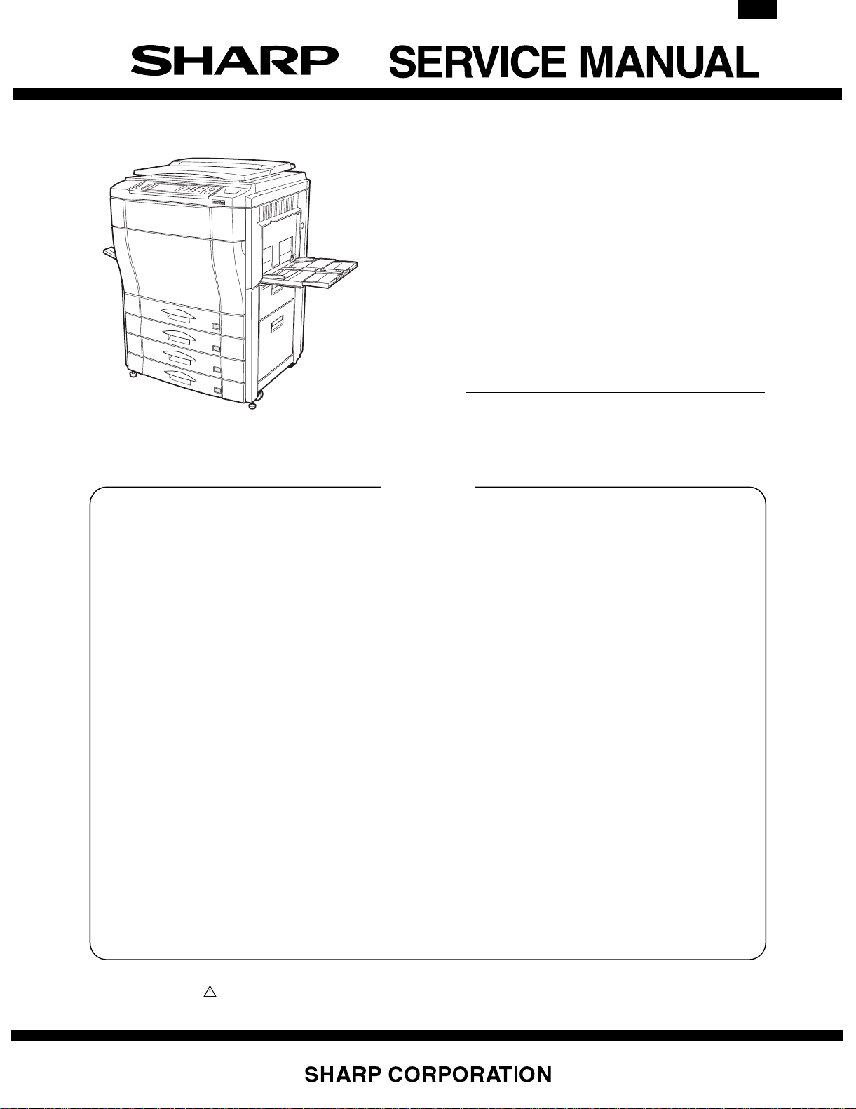
DIGITAL FULL
COLOR COPIER
MODEL AR-C150
CONTENTS
[ 1 ] CONFIGURATION . . . . . . . . . . . . . . . . . . . . . . . . . . . . . . . . . . . 1-1
[ 2 ] SPECIFICATIONS . . . . . . . . . . . . . . . . . . . . . . . . . . . . . . . . . . . 2-1
[ 3 ] CONSUMABLE PARTS . . . . . . . . . . . . . . . . . . . . . . . . . . . . . . . 3-1
[ 4 ] SETUP . . . . . . . . . . . . . . . . . . . . . . . . . . . . . . . . . . . . . . . . . . . . 4-1
[ 5 ] EXTERNAL VIEW AND INTERNAL STRUCTURE . . . . . . . . . . 5-1
[ 6 ] MACHINE OPERATIONS . . . . . . . . . . . . . . . . . . . . . . . . . . . . . 6-1
[ 7 ] SETTING AND ADJUSTMENTS . . . . . . . . . . . . . . . . . . . . . . . . 7-1
[ 8 ] SIMULATION . . . . . . . . . . . . . . . . . . . . . . . . . . . . . . . . . . . . . . . 8-1
[ 9 ] USER PROGRAM . . . . . . . . . . . . . . . . . . . . . . . . . . . . . . . . . . . 9-1
[10] SELF DIAG MESSAGE AND TROUBLESHOOTING . . . . . . . 10-1
[11] MAINTENANCE AND DISASSEMBLY/ASSEMBLY . . . . . . . . 11-1
[12] BLOCK DIAGRAM . . . . . . . . . . . . . . . . . . . . . . . . . . . . . . . . . . 12-1
[13] ACTUAL WIRING CHART . . . . . . . . . . . . . . . . . . . . . . . . . . . . 13-1
[14] OTHERS . . . . . . . . . . . . . . . . . . . . . . . . . . . . . . . . . . . . . . . . . 14-1
Parts marked with “ ” are important for maintaining the safety of the set. Be sure to replace these parts with specified
ones for maintaining the safety and performance of the set.
This document has been published to be used
for after sales service only.
The contents are subject to change without notice.
Page 2
AR-C150
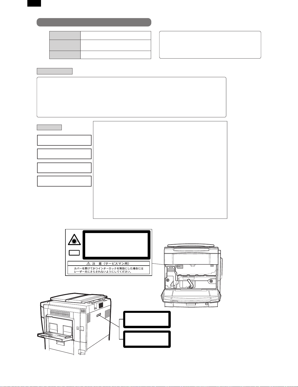
Cautions on laser
Wave length 785 nm
Pulse times
North America: (4.374 µs ±4.4 ns)/7 mm
Europe: (5.732 µs ±5.7 ns)/7 mm
+10 nm
-15 nm
Output power 0.25 - 0.45 mW
Caution
This product contains a low power laser device. To ensure
continued safety do not remove any cover or attempt to
gain access to the inside of the product. Refer all
servicing to qualified personnel.
For North America:
SAFETY PRECAUTIONS
This Digital Copier is rated Class 1 and complies with 21 CFR 1040.10 and 1040.11 of the CDRH standards.
This means that the copier does not produce hazardous laser radiation. For your safety, observe the
precautions below.
●
Do not remove the cabinet, operation panel or any other covers.
●
The copier’s exterior covers contain several safety interlock switches. Do not bypass any safety interlock by
inserting wedges or other items into switch slots.
For Europe:
CLASS 1 LASER PRODUCT
LASER KLASSE 1
LUOKAN 1 LASERLAITE
KLASS 1 LASERAPPARAT
INVISIBLE LASER RADIATION
CAUTION
WHEN OPEN AND INTERLOCKS
DEFEATED. AVOID EXPOSURE
TO BEAM.
VORSICHT
UNSICHTBARE
LASERSTRAHLUNG WENN
ABDECKUNG GEÖFFNET UND
SICHERHEITSVERRIEGELUNG
ÜBERBRÜCKT. NICHT DEM
STRAHL AUSSETZEN.
ADVARSEL
USYNLIG LASERSTRÅLNING VED
ÅBNING, NÅR
SIKKERHEDSBRYDERE ER UDE
AF FUNKTION. UNDGÅ
UDSAETTELSE FOR STRÅLNING.
LAITTEEN KÄYTTÄMINEN
MUULLA KUIN TÄSSÄ
KÄYTTÖOHJEESSA MAINITULLA
TAVALLA SAATTAA ALTISTAA
KÄYTTÄJÄN
TURVALLISUUSLUOKAN 1
YLITTÄVÄLLE NÄKYMÄTTÖMÄLLE
LASERSÄTEILYLLE.
OM APPARATEN ANVÄNDS PÅ
ANNAT SÄTT ÄN I DENNA
BRUKSANVISNING
SPECIFICERATS, KAN
ANVÄNDAREN UTSÄTTAS FÖR
OSYNLIG LASERSTRÅLNING,
SOM ÖVERSKRIDER GRÄNSEN
FÖR LASERKLASS 1.
VAROITUS!
VARNING
INVISIBLE LASER RADIATION WHEN OPEN AND INTERLOCKS DEFEATED.
AVOID EXPOSURE TO BEAM.
CAUTION
UNSICHTBARE LASERSTRAHLUNG WENN ABDECKUNG GEÖFFNET UND
SICHERHEITSVERRIEGELUNG ÜBERERÜCKT. NICHT DEM STRAHL AUSSETZEN.
VORSICHT
USYNLIG LASERSTRÅLING VED ÅBNING, NÅR SIKKERHEDSAFBRYDERE ER
UDE AF FUNKTION. UNDGÅ UDSAETTELSE FOR STRÅLNING.
ADVARSEL
USYNLIG LASERSTRÅLING NÅR DEKSEL ÅPNES OG SIKKERHEDSLÅS BRYTES.
UNNGÅ EKSPONERING FOR STRÅLEN.
ADVERSEL
OSYNLIG LASERSTRÅLNING NÄR DENNA DEL ÄR ÖPPNAD OCH SPÄRRAR ÄR
URKOPPLADE. STRÅLEN ÄR FARLIG. BETRAKTA EJ STRÅLEN.
Laserstrahl
VARNING
AVATTAESSA JA SUOJALUKITUS OHITETTAESSA OLET ALTTIINA NÄKYMÄTÖNTÄ
LASERSÄTEILYLLE. ÄLÄ KATSO SÄTEESEEN.
VARO!
CLASS 1
LASER PRODUCT
LASER KLASSE 1
(Caution on power source)
Before servicing, be sure to disconnect the power plug from the power outlet.
Page 3

[1] CONFIGURATION
1. Main unit and option lineup
(1) Main unit lineup
(2) Option lineup
AR-C150
AR-C150
AR-LC2/Large capacity tray (excluding Japan) AR-RF1/Reversing automatic document feeder AR-DU2/Duplex module
AR-CS2/500 sheet paper drawer AR-SS2/20 bin staple sorter
AR-VR2/Original cover (excluding Japan)
Fiery/Printer controller (AR-PE1)
Printer engine I/F kit (AR-PX1)
1 – 1
Page 4

AR-C150
(3) Option combinations
Option
Name Model
Large capacity tray AR-LC2 AR-C150 Supplied from the copier body. Outside of Japan only
Reversing automatic document feeder AR-RF1 AR-C150 Supplied from the copier body.
Duplex module AR-DU2 AR-C150 Supplied from the copier body.
500 sheet paper drawer AR-CS2 AR-C150 Supplied from the copier body.
20 bin staple sorter AR-SS2 AR-C150 Supplied from the copier body.
Department supervision card reader (Japan only) AR-EC1 AR-C150 Supplied from the copier body. Japan only
Fiery Printer controller/Printer engine I/F kit AR-PE1/AR-PX1 AR-C150 Supplied from the copier body.
Original cover AR-VR2 AR-C150 Outside of Japan only
RADF AR-RF1 ❍ ❍ ❍❍❍❍—
Duplex module AR-DU2 ❍❍❍❍✕—
Paper feed tray AR-CS2 ❍❍❍❍—
LCC (Outside of Japan only) AR-LC2 ❍❍❍—
20 bin staple sorter AR-SS2 ❍❍—
Department supervision card reader AR-EC1 ▲ —
Fiery Printer controller/Printer engine I/F kit AR-PE1/AR-PX1 —
❍: Possible ✕: Not possible ▲: Possible; however, only operational in copy mode (does not operation in printer mode)
Product Name Power source Note
Fiery
Printer
controller
Department
supervision
card reader
(Japan only)
20 bin
staple
sorter
LCC
(Outside
of Japan
only)
500
sheet
paper
drawer
Duplex
module
RADF
2. Block diagram
Toner hopper section
M
YK
C
RADF unit (Option)
Image scanning (writing) section
(SCAN ICU PWB / IMAGE ICU PWB / MAIN ICU PWB)
Scanner
(writing)
section (Y)
OPC section
(Y)
Developing
section (Y)
Image forming section
Scanner
(writing)
section (M)
OPC section
(M)
Developing
section (M)
Scanner
(writing)
section (C)
OPC section
(C)
Developing
section (C)
Scanner
(writing)
section (K)
OPC section
(K)
Developing
section (K)
Operation section
Engine control section
(MAIN PCU PWB / SUB PCU PWB)
DC power unit
AC power unit
Sorter unit
(Option)
Fusing/
paper exit
section
Transfer section
Duplex section (Option) / Paper feed tray section 4 (Option)
Paper feed tray section 1
Paper feed tray section 2
Paper feed tray section 3
1 – 2
Paper
transport
section
Large capacity
paper feed tray
(Option)
Page 5

[2] SPECIFICATIONS
AR-C150
1. Basic specifications
(1) Type
Type Console
Operation mode Format
Copy mode Full-color digital (electronic photographic)
(2) Target users
Mode Volume of usage
Copy mode Scope 5,000 to 20,000 sheets/month
Average copy volume 8,000 to 12,000 sheets/month
(3) External dimensions
AR-C150 AR-C100
Packaged —
Main unit 750×695×1010mm
(29.5×27.4×39.8) (height:
floor to glass surface)
750×695×1060mm
(29.5×27.4×41.7) (height:
floor to OC top surface)
725×695×1010mm
(28.5×27.4×39.8) (height:
floor to glass surface)
725×695×1060mm
(28.5×27.4×41.7) (height:
floor to OC top surface)
(4) Weight
AR-C150 AR-C100
Packaged About 164.6Kg
(363 lbs)
Main unit 152Kg (335 lbs) 155Kg (342 lbs)
About 167.6Kg
(370 lbs)
(5) Machine life
Total (copy and print) volume 800,000 sheets
Lifetime 5 years
2. Operating specifications
A. Common operations
(1) Warm-up time/Jam recovery time
a. Warm-up time (ambient temp. of 20°C)
After turned on Max. 200 seconds
Recovery from warm-up mode AR-C100 130 seconds
AR-C150 30 seconds
b. Jam recovery time
Jam
recovery time
Under 30 seconds (conditions: door open/fusing
unit drawn)
Under 8 seconds (conditions: door open)
B. Copy mode
(1) Document size
Scan mode Paper type Location
Original
stand mode
RADF mode AB Series Japan A5 A3 A3, B4, A4, A4R, B5, B5R, A5
AB Series Japan B5 A3 A3, B4, A4, A4R, B5, B5R
Australia
Other A A3, B4, A4, A4R, A5
Other B B5 A3, B4, A4, A4R, B5, B5R
Inch Series 8.5 × 5.5 11 × 17 11 × 17, 8.5 × 14, 8.5 × 11, 8.5 × 11R, 8.5 × 5.5
Australia A3, A4, A4R, A5, 216 × 330mm, B4
Other A A3, B4, A4, A4R, A5
Other B A3, B4, A4, A4R, B5, B5R, A5
Inch Series 8.5 × 5.5 11 × 17 11 × 17, 8.5 × 14, 8.5 × 11, 8.5 × 11R, 8.5 × 5.5
(2) Paper size
Paper type
AB Series
Inch Series
Dimensions Paper size
Min. Max. Min. Max.
——
——
A6 (A6R) Postcard A3 wide (305 × 457 mm) A3 wide (305 × 457 mm)
(3) Exposure
a. Exposure mode
Exposure mode Density adjustment steps Note
Color Character/photo (Auto) — Color balance, density (fixed)
Character/photo (Manual) 9 steps
Character (Auto) (AR-C150 only) — Color balance, density (fixed)
Character (Manual) (AR-C150 only) 9 steps
Printing photo (AR-C150 only)
Photographic paper photo
Mapping (AR-C150 only)
Monochrome Character/photo (Auto) — Performs prescan operations (*)
Character/photo (Manual) 9 steps
Character (Auto) (AR-C150 only) — Performs prescan operations (*)
Character (Manual) (AR-C150 only) 9 steps
Printing photo (AR-C150 only)
Photographic paper photo
Mapping
* Can set the presence of prescans by t he user program.
Dimensions Paper size
Min. Max. Min. Max.
A5
8.5 × 5.5 12 × 18 12 × 18, 11 × 17, 8.5 × 14,
A3, A4, A4R, A5, 216 × 330mm
A3, B4, A4, A4R, B5, B5R, A5
8.5 × 11, 8.5 × 11R, 8.5 × 5.5
Paper sizes Note
Paper sizes Note
2 – 1
Page 6

AR-C150
b. Resolution
• Read
Main scanning direction Sub scanning direction
Basic resolution Basic resolution
600dpi 600dpi
• Write
Main scanning direction Sub scanning direction
Basic resolution Basic resolution
600dpi 600dpi
c. Gradation/ image processing
Mode Scanning Printing Image processing/gradation control format
Color Character/photo (Auto) 256 gradations (8bit) 256 gradations (8bit) Area separation, filter processing, dither pattern
Character/photo (Manual) 256 gradations (8bit) 256 gradations (8bit) Area separation, filter processing, dither pattern
Character (Auto) (AR-C150 only) 256 gradations (8bit) 256 gradations (8bit) Area separation, filter processing, dither pattern
Character (Manual) (AR-C150 only) 256 gradations (8bit) 256 gradations (8bit) Area separation, filter processing, dither pattern
Printing photo (AR-C150 only) 256 gradations (8bit) 256 gradations (8bit) Filter processing, dither pattern
Photographic paper photo 256 gradations (8bit) 256 gradations (8bit) Filter processing, dither pattern
Mapping (AR-C150 only) 256 gradations (8bit) 256 gradations (8bit) Filter processing, dither pattern
Monochrome Character/photo (Auto) 256 gradations (8bit) 256 gradations (8bit) Area separation, filter processing, dither pattern
Character/photo (Manual) 256 gradations (8bit) 256 gradations (8bit) Area separation, filter processing, dither pattern
Character (Auto) (AR-C150 only) 256 gradations (8bit) 256 gradations (8bit) Area separation, filter processing, dither pattern
Character (Manual) (AR-C150 only) 256 gradations (8bit) 256 gradations (8bit) Area separation, filter processing, dither pattern
Printing photo (AR-C150 only) 256 gradations (8bit) 256 gradations (8bit) Filter processing, dither pattern
Photographic paper photo 256 gradations (8bit) 256 gradations (8bit) Filter processing, dither pattern
Mapping 256 gradations (8bit) 256 gradations (8bit) Filter processing, dither pattern
d. Distortion
203mm
e. Toner save mode
Toner save
percentage
Approx 15% ∗ Can only be set for monochrome
Print horizontal line
D
| D |
Print
vertical line
mode (set by key operator) (Set by
simulation in Japan and the U.K.)
1m
60 m
(4) Copy magnification
a. Copy magnification (independent magnification by direction
is possible)
Main scanning direction Sub scanning direction
Magnification
Mode
Zoom mode 25/50 to 400% Zoom mode 25/50 to 400%
Fixed
magnification
mode
(AB Series)
Fixed
magnification
mode
(Inch Series)
range/fixed
magnification
25,50,70,81,86,
100,115,122,141,
200,400%
25,50,64,77,95,
100,121,129,141,
200,400%
Mode
Fixed
magnification
mode
(AB Series)
Fixed
magnification
mode
(Inch Series)
Magnification
range/fixed
magnification
25,50,70,81,86,
100,115,122,141,
200,400%
25,50,64,77,95,
100,121,129,141,
200,400%
∗ The minimum copy magnification for the AR-C100 is 50%.
b. Copy magnification precision
Main scanning direction Sub scanning direction
Copy
magnification
Normal copy 100%±0.8% Normal copy 100%±0.8%
Enlargement
copy
Reduction
copy
c. Zoom method
Main scanning direction Performed through image processing
Sub scanning direction Performed by changing image
Magnification
precision
Set magnification
±1.0%
Set magnification
±1.0%
processing and scanning speed
Copy
magnification
Enlargement
copy
Reduction
copy
Magnification
precision
Set magnification
±1.0%
Set magnification
±1.0%
2 – 2
Page 7

AR-C150
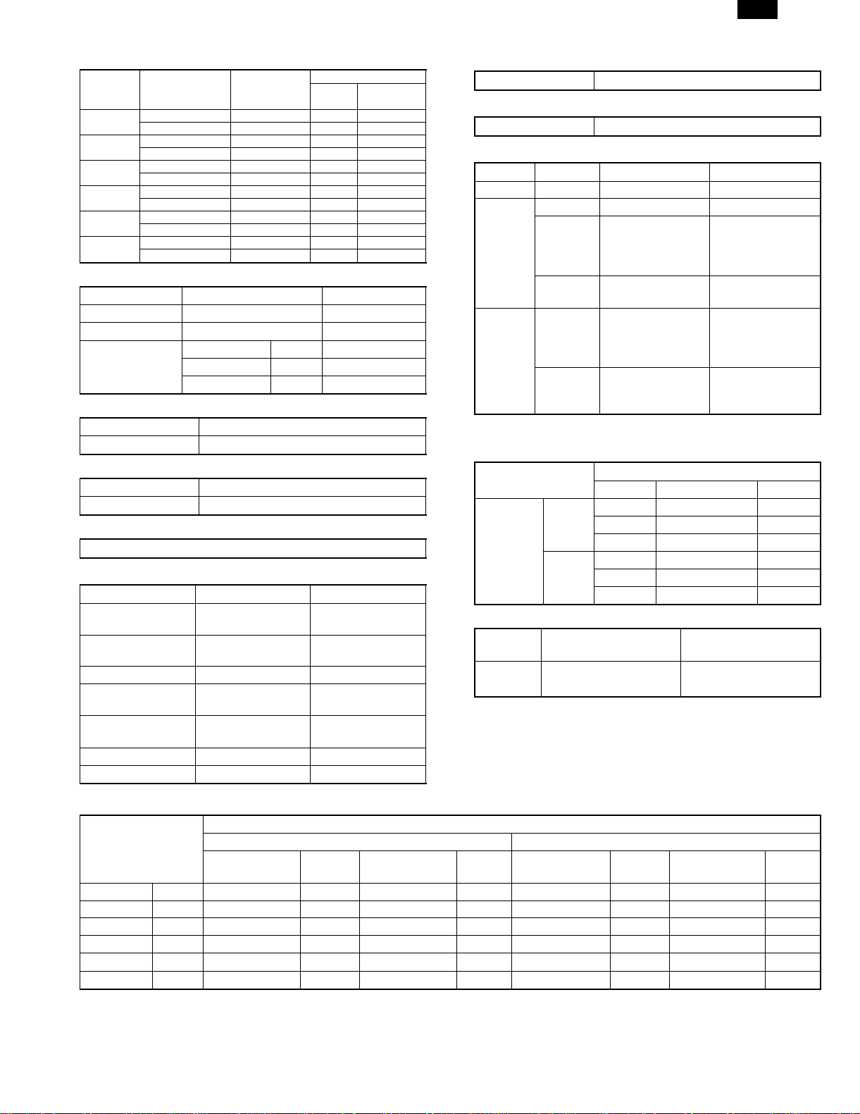
(5) Job speed
Copy method for each copy mode
Black-and-white copy Color copy
Up to A4/LT B4/RG to A3/WLT Up to A4/LT B4/RG to A3/WLT
Single-side copy 1 scan/multi-copy 1 scan/multi-copy Multi scan/copy Multi scan/copy Multi scan/copy
Duplex copy 1 scan/multi-copy Multi scan/copy * Multi scan/copy * Multi scan/copy * —
* No multi-copy mode, only single copy
a. First copy time
A3 wide copy
• Original stand mode (non SPF/ADF/RADF mode) (Unit: sec.)
Paper supply mode Paper size Color Monochrome
Manual feed 8.5 × 11, A4 9.8 19.5
A4, 11 × 8.5 (OHP) 84.8 94.5
B5, A4, 11 × 8.5 (thick paper) 69.8 79.5
1st paper feed tray A4 10.5 19.5
8.5 × 11 10.5 19.5
2nd paper feed tray A4 11.3 20.3
8.5 × 11 11.3 20.3
3rd paper feed tray A4 12.2 21.2
8.5 × 11 12.2 21.2
4th paper feed tray A4 13.1 22.1
8.5 × 11 13.1 22.1
LCC A4 10.2 19.5
8.5 × 11 10.2 19.5
∗ 1st paper feed tray is installed for optional slot.
b. Multi-copy speed
(Conditions) Scanner speed: 15 cpm, using A4/letter standard paper, and no prescan
Conditions) S → S color: One copy of A4 (L1) original (10 sheets), no optional settings other than RADF, and not including fast copy
Color Monochrome
Copy mode Paper size
Reduction
copy (25%)
Original
stand
mode
The numbers in the parenthesis are the copy speeds when the 4th paper cassette is used.
c. Maximum no. of copies
Multi max. quantity 999 sheets
S → S A3 7 7 6 13 13 13
A3 wide(12 × 18) 776777
B4 9 9 8 15 15 15
A4 15 15 12 25 (24) 25 (24) 25 (24)
A4R 11 11 10 19 19 19
A5 15 15 12 25 25 25
B5 15 15 12 25 25 25
B5R 11 11 10 19 19 19
11 × 17 7 7 6 13 13 13
8.5 × 14 9 9 8 15 15 15
8.5 × 11 15 15 12 25 25 25
8.5 × 11R 11 11 10 19 19 19
8.5 × 5.5 15 15 12 25 (24) 25 (24) 25 (24)
8.5 × 13/F.S 9 9 8 15 15 15
A4, 11 × 8.5 (OHP) 10 10 10 10 10 10
B5,A4,11×8.5 (thick paper) 10 10 10 10 10 10
Other than B5, A4,
11 × 8.5 (thick paper)
555555
1 scan:1 copy 1 scan:Multiple copy
Copy magnification Copy magnification
Normal copy
(100%)
Enlargement
copy (400%)
Reduction
copy (25%)
Normal copy
(100%)
• Maximum number of copies that can be set for each copy mode
Black-and-white copy Color copy
Single-side
copy
Duplex
copy
Up to
A4/LT
999 999 999 999 999
999 1 1 1 —
B4/RG to
A3/WLT
Up to
A4/LT
B4/RG to
A3/WLT
Enlargement
copy (400%)
A3
wide
copy
2 – 3
Page 8
AR-C150
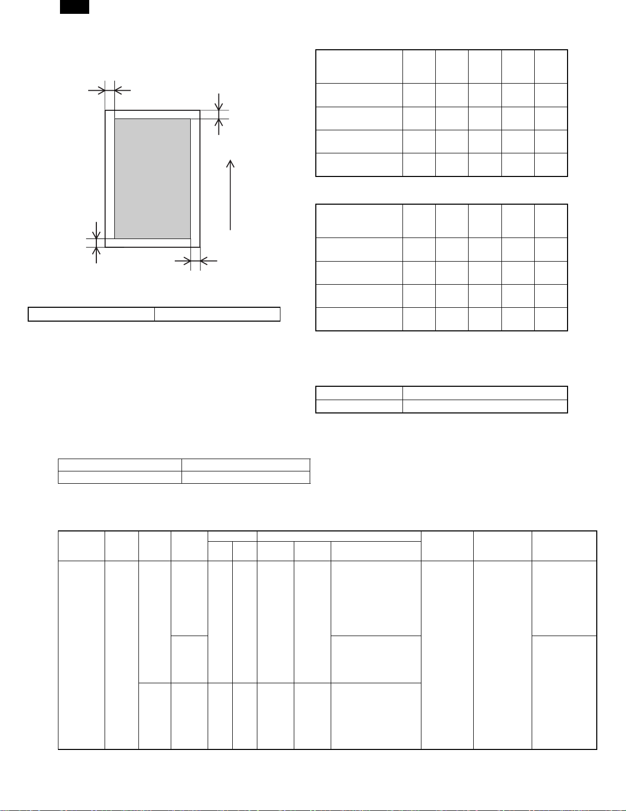
(6) Copy area
C
(Front edge)
Printed image
(image area)
B
(Rear edge)
Dimensions show void area
Copy area 297 × 432mm
• Image loss
Front
edge
One side copy
(excluding A3(11×17))
A
One side copy for
A3(11×17)
Max.
5mm
Max.
5mm
Duplex copying Max.
5mm
OHP copying Max.
10mm
Feeding
direction
∗ 0mm image loss for A3 originals and A3 wide copying.
• Void area
Front
edge
One side copy
(excluding A3(11×17))
One side copy for
D
A3(11×17)
Max.
5mm
Max.
5mm
Duplex copying Max.
5mm
OHP copying Max.
10mm
(7) Languages supported
Japanese, English (USA/UK), German, French, Spanish, Italian,
Dutch, Sweden
(8) Internal auditor
Format Key operation/card operation (optional)
No. of departments 400 (200 with card type)
(A)
(A)
Rear
edge
(B)
Max.
5mm
Max.
7mm
Max.
7mm
Max.
10mm
Rear
edge
(B)
Max.
5mm
Max.
7mm
Max.
7mm
Max.
10mm
Total
(C+D)
Max.
6mm
Max.
6mm
Max.
6mm
Max.
6mm
Total
(C+D)
Max.
6mm
Max.
6mm
Max.
6mm
Max.
6mm
Left
edge
(C)
Max.
3.0mm
Max.
3.0mm
Max.
3.0mm
Max.
3.0mm
Left
edge
(C)
Max.
3.0mm
Max.
3.0mm
Max.
3.0mm
Max.
3.0mm
Right
edge
(D)
Max.
3.0mm
Max.
3.0mm
Max.
3.0mm
Max.
3.0mm
Right
edge
(D)
Max.
3.0mm
Max.
3.0mm
Max.
3.0mm
Max.
3.0mm
3. Engine specifications
A. Operation (display/operation) section
Display Large mono-color LCD display
Operating procedure Touch-panel input
B. Paper feeding, paper conveyance, and discharge section
(1) Paper feeding performance
a. Paper feed ability
Paper feed
mode
(section)
Manual feed
section
(Multi paper
feed)
Feed
method
—
Paper
type
AB
Series
Inch
Series
Location
Japan
Others A3 wide, A3, B4, A4, A4R,
Dimensions Paper size
Min. Max. Min. Max. Paper sizes
——
——
A6(A6R)
Postcard
8.5×5.5 12×18 12×18, 11×17, 8.5×14,
A3 wide
(12×18)
A3 wide, A3, B4, A4, A4R,
B5, B5R,
A5, Postcard, 11×17,
8.5×14, 8.5×11
(Document guide display:
11, 8.5, A3 wide, A3, B4,
A4, A4R, B5, B5R, A5,
A5R, B6R, A6R, Postcard)
B5, A5, A6R, 11×17,
8.5×14, 8.5×11,
7.25×10.5R
(Document guide display:)
8.5×11, 8.5×11R, 8.5×5.5,
7.25×10.5R, A3, B4, A4,
B5, A6R
(Document guide display:
12, 11,
8.5, 5.5, A3, B4, A4, B5)
Paper weight Capacity Note
2
60 to 200g/m
(16 to 55lbs.)
50 sheets (6mm)
(max. 80g/m
paper)
Special paper
2
(OHP film),
(recommended
product), Postcard
and thick paper
Special paper
(OHP film) and
thick paper
2 – 4
Page 9

AR-C150
Paper feed
mode
(section)
Manual feed
section
(Single
paper feed)
1st to 4th
cassette
feeding unit
Feed
method
—
—
Paper
type
AB
Series
Inch
Series
AB
Series
Inch
Series
Location
Japan
Others A3 wide, A3, B4, A4, A4R,
Japan
Others A3, B4, A4, A4R, B5, A5,
Dimensions Paper size
Min. Max. Min. Max. Paper sizes
——
——
——
——
A6(A6R)
Postcard
8.5×5.5 12×18 12×18, 11×17, 8.5×14,
A5 A3 A3, B4, A4, A4R, B5, B5R,
8.5×5.5 11×17 11×17, 8.5×14, 8.5×13,
A3 wide
(12×18)
A3 wide, A3, B4, A4, A4R,
B5, B5R, A5, Postcard,
11×17, 8.5×14, 8.5×11
(Document guide display:
11, 8.5, A3 wide, A3, B4,
A4, A4R, B5, B5R, A5,
A5R, B6R, A6R, Postcard)
B5, A5, A6R, 11×17, 8.5×
14, 8.5×11, 7.25×10.5R
(Document guide display:)
8.5×11, 8.5×11R, 8.5×5.5,
7.25×10.5R, A3, B4, A4,
B5, A6R
(Document guide display:
12, 11, 8.5, 5.5, A3, B4,
A4, B5)
A5, EXTRA
8.5×11
8.5×11, 8.5×11R, 8.5×5.5,
A4, EXTRA
Paper weight Capacity Note
60 to 200g/m
(16 to 55lbs.)
60 to 105g/m
(16 to 28lbs.)
b. Document detection
Paper feed
mode (section)
Manual feed
section
Paper type Location
of use
Detection size
AB Series Japan A3 wide,A3,B4,A4,A4R,B5,B5R,A5,
Postcard, 11×17,8.5×14,8.5×11
Others A3 wide,A3,B4,A4,A4R,B5,A5,A6R,
11×17,8.5×14,8.5×11,7.25×10.5R
Paper detection size and
detection method
Electrical resistance
changes according to
position of paper width
guide (volume sensor)
Inch Series 12×18,11×17,8.5×14,8.5×11,
8.5×11R,8.5×5.5,A3,B4,A4,
B5,A6R,7.25×10.5R
1st to 4th
cassette
feeding unit
AB Series Japan A3,B4,A4,A4R,B5,B5R,A5,EXTRA Detection method by
Others A3,B4,A4,A4R,B5,A5,8.5 ×11,EXTRA
Inch Series 11×17,8.5×14,8.5×13,8.5×11,
8.5×11R,8.5×5.5,A4,EXTRA
switch signal combination
(switches paper detection
block position)
∗ When setting the paper size switch to EXTRA, it is necessary to set the paper size by key operation.
∗ For A and B sizes (excluding Japan), it is necessary to set the paper size switch to EXTRA for 13" and B5R.
(2) Finishing performance
Facing
mode
Face up All paper
Paper size Paper weight Capacity Note
All paper sizes that
sizes
can be fed
250
sheets
c. Scanning area
2
50 sheets
(6mm) (max.
2
paper)
80g/m
2
500 sheets×3
(4) (max. 80g/m
paper)
500 sheets×3
(4) (max. 80g/m
paper)
Size switching
method
Aligns with paper
width guide
(sliding type)
Aligns universal
guide (sliding type)
Center
Special paper
(OHP film),
Postcard and thick
paper
Special paper
(OHP film) and
thick paper
2
2
Note
Remaining
amount detector
C. Scanner section
(1) Type
Scanning method By 3-color (RGB) CCD image sensor
(2) Original standard position, scanning size, and
scanning area
a. Original standard position
Left-center
b. Scanning size
Max. original size AB Series A3
Inch Series 11 × 17
356 mm
216 mm
2 – 5
Page 10

AR-C150
(3) Resolution
Main scanning direction Sub scanning direction
Basic resolution Basic resolution
600dpi 600dpi
(4) Gradation
Input Output
Monochrome 256 gradations (8bit) 256 gradations (8bit)
Color 256 gradations (8bit) 256 gradations (8bit)
(5) Scanning speed
Original size
A4 (11" ×
8.5")
15 sheets/
min
15 sheets/
min
A3 (11" ×
17")
7 sheets/
min
7 sheets/
min
Scan mode Scan Return
Color
Monochrome
117
mm/sec
117
mm/sec
468
mm/sec
468
mm/sec
Scans per
minute
15 sheets/
min
15 sheets/
min
(6) Light source
Type Halogen lamp
Drive voltage 70V
Power consumption 130W
(7) Scanning sensor
Type 3-line color CCD
(8) Color separation method
Color separation by 3-color (RGB) CCD image sensor
D. Scanner section
(1) Type
Type Laser scanning
(2) Laser unit specifications
Speed of rotation 27,600rpm
Mirror surfaces 6 surfaces
Laser power 5mW
Laser beam size 80µm
Laser wavelength 785µm
Scan width
(sub scan direction)
AB Series: 420mm Inch Series: 432mm
(3) Resolution
Main scanning direction Sub scanning direction
600dpi 600dpi
(4) Gradation
Monochrome 256 gradations (8bit)
Color 256 gradations (8bit)
E. Image processing section
(1) Imaging speed
117 mm/sec
(2) Photosensitive drum
Type OPC φ40mm (4 pieces)(C, M, Y, K)
Life 40,000 sheets
Form Cartridge
(3) Toner
Black Color (C, M, Y)
Type —
Capacity 600g 267g each
Life (A4: each color
10%)
Form Cartridge
8,000 sheets 4,000 sheets each
(4) Developer
Black Color (C, M, Y)
Type Ferrite type
Capacity 650g 650g each
Life 40,000 sheets 40,000 sheets each
(5) Charging system
Charging system DC negative scorotron (saw tooth electrode)
Voltage –320V to –830V
(6) Exposure
Method Exposure from laser diode
(7) Developing system
Developing system Dry, 2-component magnetic brush development
Voltage –120V to –600V
(8) Transfer
Method DC positive static electricity transfer (transfer belt method)
Voltage 1.75 to 5KV
(9) Release
Method Curvature release + releasing tabs
(10) Discharging
Method Discharging lamp method
(11) Cleaning
Method Blade method
(12) Toner compartment capacity
Black Color (C, M, Y)
Capacity 600g 267g
Printed sheets (10% density) 8K 4K
(13) Waste toner collector capacity
Capacity —
Printed sheets 40K
(14) Correction functions
Correction functions Toner density correction (toner density
control level correction)
Drum sensitivity correction (laser power
control level correction)
Transfer-ability correction (transfer voltage
control level correction)
Developing-ability correction (developing
bias voltage control level correction)
Halftone correction (laser power duty
control level correction)
F. Fuser section
(1) Type
Fusing system Heat roller system (oil usage)
2 – 6
Page 11
AR-C150
(2) Lamp
Main unit
voltage
ratings
100V Main heater lamp Halogen lamp 100V 1000W
110V Main heater lamp Halogen lamp — —
120V Main heater lamp Halogen lamp 120V 1000W
127V Main heater lamp Halogen lamp — —
220 to 230V Main heater lamp Halogen lamp 230V 1300W
240V Main heater lamp Halogen lamp 230V 1300W
Lamp Type
Sub heater lamp Halogen lamp 100V 700W
Sub heater lamp Halogen lamp — —
Sub heater lamp Halogen lamp 120V 700W
Sub heater lamp Halogen lamp — —
Sub heater lamp Halogen lamp 230V 700W
Sub heater lamp Halogen lamp 230V 700W
Voltage
Lamp rating
Power
consumption
(3) Fuser temperature
Upper heat roller Lower heat roller
Ready condition 177°C 132°C
Power save mode 137°C OFF
Print mode Standard paper 170°C 125°C
OHP sheet 180°C 175°C
Thick paper 180°C 135°C
(4) Heat roller
Type Silicone rubber roller
Life 40K
(5) Pressure roller
Type Silicone rubber roller
Life 40K
(6) Release method
Forced release by releasing tabs (AR-C150 only)
G. Drive section
Drive section Motor name Motor type
Toner hopper
(C, M, Y, K)
Photosensitive drum
(C, M, Y, K)
Image scanner Scanner motor Stepping motor
Developing
(C, M, Y, K)
Paper feed and
conveyance
Transfer belt Transfer belt motor Stepping motor
Fusing Fusing motor DC brush-less motor
Toner motor
Synchronous motor
(Y, M, C, K)
Drum motor
Stepping motor
(Y, M, C, K)
Developing motor
DC brush-less motor
(Y, M, C, K)
Paper feed motor DC brush-less motor
H. Engine controller
Processor M68334
I. Image processing controller
Processor MCF5202
J. Memory
Type Capacity Memory contents Location
DRAM 128MB Image data ICU MAIN PWB
Flash
ROM
32Mbit Program data ICU MAIN PWB
16Mbit
Program data PCU PWB
(AR-C150)
8Mbit
(AR-C100)
16Mbit Program data Operation control
PWB
EEPROM 64Kbit
(AR-C100)
256Kbit
Setting,
adjustment, counter
data, etc.
PCU PWB
(AR-C150)
64Kbit
Setting,
adjustment, counter
ICU MAIN PWB
data, etc.
K. Power source
(1) DC power supply
Output
Image scanner section
(optional outside of Japan)
DC power
supply
Type
Main 24V 15A
Voltage Capacity (current) Note
5.1V 7.5A
3.4V 5.5A
Sub 26V 0.5A
5V2 1.1A
5Vs 0.1A
(2) Dehumidifier functionality
Section Paper conveyor section
Method Surface heater Surface heater
(Japan only)
* With ON/OFF switch
(3) Operating voltage/power consumption
Power consumption
Power supply
voltage/frequency
Preheat
condition
100V 50/60Hz Max. 101W — Max. 10W 1500W — — — 1500W
110V 50/60Hz Max. 101W — Max. 10W 1500W — — — 1500W
120V 50/60Hz Max. 101W — Max. 10W 1500W — — — 1500W
127V 50/60Hz Max. 101W — Max. 10W 1500W — — — 1500W
220 to 230V 50/60Hz Max. 101W — Max. 10W 1800W — 1175W — 1800W
240V 50/60Hz Max. 101W — Max. 10W 1800W — 1325W — 1800W
Main unit With full options
Ready
condition
Sleep mode
condition
Max.
Preheat
condition
Ready
condition
2 – 7
Sleep mode
condition
Max.
Page 12

AR-C150
4. Safety and environmental protection
standards
A. Safety standards
Item Standard Country
Safety standards S Mark Japan
UL U.S.A
SEMKO Sweden
GS Mark Germany
Environmental standards FCC U.S.A
VCCI Japan
CE Europe
C-tick Australia
B. Environmental standards
(1) Power consumption and environmental standards
Item Standard Country
Power consumption Energy Star Japan, U.S.A,
Europe
ECP, Nordic Canada
Environmental standards Swan, Nordic Sweden
(2) Ozone level
Max. 0.02mg/m
(3) Noise level
Noise mode
Noise power level Max. 66dB Max. 40dB —
Noise pressure level — — —
3
Main unit
During
operation
Ready
condition
Sleep mode
condition
5. Ambient conditions
A. Space required
(1) Area required
AR-C150 AR-C100
Main unit 1412 × 695mm
(55.6" × 27.4")
With full options 1504 × 695mm
(59.2" × 27.4")
1453 × 695mm (Japan)
1220 × 695mm
—
C. Ambient storage conditions
Humidity
RH
90%
10%
Humidity
RH
90%
20%
–10˚C 50˚C
Consumable items (unopened)
–5˚C 40˚C
Main unit
40˚C, 90%
Temperature
40˚C, 90%
Temperature
D. Ambient conditions for transporting
Humidity
RH
90%
20%
Main unit
30˚C, 90%
50˚C, 60%
45˚C, 60%
B. Operating ambient conditions
(1) Temperature/Humidity
Humidity
RH
80%
20%
15˚C 35˚C
Temperature
(2) Power supply voltage and frequency
Power supply voltage Rated voltage ±10%
Power supply frequency Rated frequency ±2%
30˚C, 80%
35˚C, 60%
20˚C 45˚C
Humidity
RH
90%
10%
–5˚C 40˚C
Temperature
Consumable items
Temperature
E. Standard temperature and humidity
Temperature 20 to 25°C
Humidity 65 ± 5%
2 – 8
40˚C, 90%
Page 13

AR-C150
[3] CONSUMABLE PARTS
1. Consumable parts list
AR-C150 Supply List (U.S.A., CANADA)
NAME CONTENT(S)
1 Color Toner (cyan) "Toner Cartridge (cyan) (267g),
Instruction Sheet"
2 Color Toner (magenta) "Toner Cartridge (magenta) (267g),
Instruction Sheet"
3 Color Toner (yellow) "Toner Cartridge (yellow) (267g),
Instruction Sheet"
4 Toner (black) "Toner Cartridge (black) (600g),
Instruction Sheet"
5 Color Developer kit [Developer (cyan × 1, magenta × 1,
yellow × 1) (650g each)
6 Black Developer kit [Developer (black) (650g) × 1 × 10 40K × 10 AR-C15MD1 204 × 391 × 290/9.10 (AR-C15ND1) × 10 =
7 Drum Unit Drum Unit × 1 40K AR-C15DU 402 × 568 × 198/6.73
(Drum/Unit Parts included) × 1
Color Seal (C, M, Y, Bk each × 2)
8 Drum Kit Drum × 1 40K AR-C15DK 418 × 146 × 519/4.60
Cleaning Blade × 1
Toner Receiving Seal × 1
Charger Unit × 1
Color Seal (C, M, Y, Bk each × 1)
LIFE
Note 1)
× 10 4K Note 1)
× 10
× 10 4K Note 1)
× 10
× 10 4K Note 1)
× 10
× 10 8K Note 1)
× 10
× 3 40K
each × 3
Model
AR-C15MT6 329 × 590 × 218/5.62 A (AR-C15NT6) × 10 =
AR-C15MT7 329 × 590 × 218/5.62 A (AR-C15NT7) × 10 =
AR-C15MT8 329 × 590 × 218/5.62 A (AR-C15NT8) × 10 =
AR-C15MT1 429 × 610 × 246/10.97 A (AR-C15NT1) × 10 =
AR-C15MD9 294 × 391 × 170/7.71 (AR-C15ND9) × 3 =
Note 1) A4 document with 10% coverage
Note 2) Inner carton printed in 2 languages including English and
French
AR-C150 supply system (USA/Canada)
No. Name Content Life Model Remark
1 Developer unit kit Developer unit × 4 — AR-DW1
2 Waste toner container kit Drum waste toner container (AS) × 1 40K AR-C15HB 5% coverage of each of C/M/Y/K, total 20% coverage
Transfer waste toner tank unit × 1
3 Fusing oil Fusing oil (800g) × 10 40K × 10 AR-C15LL AR-C15LL = AR-C15SL × 10
4 Upper heat roller kit Upper heat roller unit × 1 40K AR-C15UH
Upper cleaning roller × 1
5 Lower heat roller kit Lower heat roller unit × 1 40K AR-C15LH
Fusing separation pawl lower × 5
6 Fusing oil applying kit Oil applying unit × 1 40K AR-C15KH
Oil filter unit × 1
Applying unit mini oil bottle × 1
7 Filter kit Process ozone filter × 2 80K AR-C15FL
Toner duct ozone filter × 1
Toner filter × 1
8 Transfer belt kit Transfer belt × 1 160K AR-C15TT
Belt separation pawl × 2
9 Transfer roller kit Transfer blade × 1 80K AR-C15TX
Transfer roller × 4
10 Staple cartridge Staple cartridge (SF-SC11) × 3 5,000 × 3 SF-SC11 For AR-S22. Common with FN1.
11 Fusing unit Fusing unit
(Except for motor, PWB,
upper/lower lamps)
12 Transfer unit Transfer unit
(Except for motor)
13 DV seal kit DV seal unit (assemble) × 3 80K AR-C15DS
× 1 AR-C15FU (For servicing)
× 1 AR-C15TU (For servicing)
DIMENSIONS
(W × D × H): mm
/WHIGHT: kg
INCOMPATIBILITY REMARK
AR-C15MT6
AR-C15MT7
AR-C15MT8
AR-C15MT1
AR-C15MD9
AR-C15MD1
3 – 1
Page 14
AR-C150
AR-C150 Supply List (Europe, Australia, New Zealand)
NAME CONTENT(S)
1 Color Toner (cyan) "Toner Cartridge (cyan) (267g),
Instruction Sheet"
2 Color Toner (magenta) "Toner Cartridge (magenta) (267g),
Instruction Sheet"
3 Color Toner (yellow) "Toner Cartridge (yellow) (267g),
Instruction Sheet"
4 Toner (black) "Toner Cartridge (black) (600g),
Instruction Sheet"
5 Color Developer kit [Developer (cyan × 1, magenta × 1,
yellow × 1) (650g each)
6 Black Developer kit [Developer (black) (650g) × 1 × 10 40K AR-C15LD1 204 × 391 × 290/9.10 (AR-C15DV1) × 10 =
7 Drum Unit Drum Unit × 1 40K AR-C15DU 402 × 568 × 198/6.73
(Drum/Unit Parts included) × 1
Color Seal (C, M, Y, Bk each × 2)
8 Drum Kit Drum × 1 40K AR-C15DK 418 × 146 × 519/4.60
Cleaning Blade × 1
Toner Receiving Seal × 1
Charger Unit × 1
Color Seal (C, M, Y, Bk each × 1)
LIFE
Note 1)
× 10 4K Note 1)
× 10
× 10 4K Note 1)
× 10
× 10 4K Note 1)
× 10
× 10 8K Note 1)
× 10
× 3 40K
each × 3
Model
AR-C15LT6 329 × 590 × 218/5.62 B (AR-C15T6) × 10 =
AR-C15LT7 329 × 590 × 218/5.62 B (AR-C15T7) × 10 =
AR-C15LT8 329 × 590 × 218/5.62 B (AR-C15T8) × 10 =
AR-C15LT1 429 × 610 × 246/10.97 B (AR-C15T1) × 10 =
AR-C15LD9 294 × 391 × 170/7.71 (AR-C15DV9) × 3 =
Note 1) A4 document with 10% coverage
Note 2) Inner carton printed in 4 languages
DIMENSIONS
(W × D × H): mm
/WHIGHT: kg
INCOMPATIBILITY REMARK
AR-C15LT6
AR-C15LT7
AR-C15LT8
AR-C15LT1
AR-C15LD9
AR-C15LD1
AR-C150 supply system (Europe, Australia, New Zealand)
No. Name Content Life Model Remark
1 Developer unit kit Developer unit × 4 — AR-DW1
2 Waste toner container kit Drum waste toner container (AS) × 1 40K AR-C15HB 5% coverage of each of C/M/Y/K, total 20% coverage
Transfer waste toner tank unit × 1
3 Fusing oil Fusing oil (80g) × 10 40K × 10 AR-C15LL AR-C15LL = AR-C15SL × 10
4 Upper heat roller kit Upper heat roller unit × 1 40K AR-C15UH
Upper cleaning roller × 1
5 Lower heat roller kit Lower heat roller unit × 1 40K AR-C15LH
Fusing separation pawl lower × 5
6 Fusing oil applying kit Oil applying unit × 1 40K AR-C15KH
Oil filter unit × 1
Applying unit mini oil bottle × 1
7 Filter kit Process ozone filter × 2 80K AR-C15FL
Toner duct ozone filter × 1
Toner filter × 1
8 Transfer belt kit Transfer belt × 1 160K AR-C15TT
Belt separation pawl × 2
9 Transfer roller kit Transfer blade × 1 80K AR-C15TX
Transfer roller × 4
10 Staple cartridge Staple cartridge (SF-SC11) × 3 5,000 × 3 SF-SC11 For AR-S22. Common with FN1.
11 Fusing unit Fusing unit
(Except for motor, PWB,
upper/lower lamps)
12 Transfer unit Transfer unit
(Except for motor)
13 DV seal kit DV seal unit (assemble) × 3 80K AR-C15DS
× 1 AR-C15FU (For servicing)
× 1 AR-C15TU (For servicing)
3 – 2
Page 15
AR-C150
AR-C150 Supply List (Asia/Central & South America &
others)
NAME CONTENT(S)
1 Color Toner (cyan) "Toner Cartridge (cyan) (267g),
Instruction Sheet"
2 Color Toner (magenta) "Toner Cartridge (magenta) (267g),
Instruction Sheet"
3 Color Toner (yellow) "Toner Cartridge (yellow) (267g),
Instruction Sheet"
4 Toner (black) "Toner Cartridge (black) (600g),
Instruction Sheet"
5 Color Developer kit [Developer (cyan × 1, magenta × 1,
yellow × 1) (650g each)
6 Black Developer kit [Developer (black) (650g) × 1 × 10 40K AR-C15CD1 204 × 391 × 290/9.10 (AR-C15SD1) × 10 =
7 Drum Unit Drum Unit × 1 40K AR-C15DU 402 × 568 × 198/6.73
(Drum/Unit Parts included) × 1
Color Seal (C, M, Y, Bk each × 2)
8 Drum Kit Drum × 1 40K AR-C15DK 418 × 146 × 519/4.60
Cleaning Blade × 1
Toner Receiving Seal × 1
Charger Unit × 1
Color Seal (C, M, Y, Bk each × 1)
LIFE
Note 1)
× 10 4K Note 1)
× 10
× 10 4K Note 1)
× 10
× 10 4K Note 1)
× 10
× 10 8K Note 1)
× 10
× 3 40K
each × 3
Model
AR-C15CT6 329 × 590 × 218/5.62 A (AR-C15ST6) × 10 =
AR-C15CT7 329 × 590 × 218/5.62 A (AR-C15ST7) × 10 =
AR-C15CT8 329 × 590 × 218/5.62 A (AR-C15ST8) × 10 =
AR-C15CT1 429 × 610 × 246/10.97 A (AR-C15ST1) × 10 =
AR-C15CD9 294 × 391 × 170/7.71 (AR-C15SD9) × 3 =
Note 1) A4 document with 10% coverage
Note 2) Inner carton printed in 4 languages
DIMENSIONS
(W × D × H): mm
/WHIGHT: kg
INCOMPATIBILITY REMARK
AR-C15CT6
AR-C15CT7
AR-C15CT8
AR-C15CT1
AR-C15CD9
AR-C15CD1
AR-C150 supply system (Middle and South America,
Asia, others)
No. Name Content Life Model Remark
1 Developer unit kit Developer unit × 4 — AR-DW1
2 Waste toner container kit Drum waste toner container (AS) × 1 40K AR-C15HB 5% coverage of each of C/M/Y/K, total 20% coverage
Transfer waste toner tank unit × 1
3 Fusing oil Fusing oil (80g) × 10 40K × 10 AR-C15LL AR-C15LL = AR-C15SL × 10
4 Upper heat roller kit Upper heat roller unit × 1 40K AR-C15UH
Upper cleaning roller × 1
5 Lower heat roller kit Lower heat roller unit × 1 40K AR-C15LH
Fusing separation pawl lower × 5
6 Fusing oil applying kit Oil applying unit × 1 40K AR-C15KH
Oil filter unit × 1
Applying unit mini oil bottle × 1
7 Filter kit Process ozone filter × 2 80K AR-C15FL
Toner duct ozone filter × 1
Toner filter × 1
8 Transfer belt kit Transfer belt × 1 160K AR-C15TT
Belt separation pawl × 2
9 Transfer roller kit Transfer blade × 1 80K AR-C15TX
Transfer roller × 4
10 Staple cartridge Staple cartridge (SF-SC11) × 3 5,000 × 3 SF-SC11 For AR-S22. Common with FN1.
11 Fusing unit Fusing unit
(Except for motor, PWB,
upper/lower lamps)
12 Transfer unit Transfer unit
(Except for motor)
13 DV seal kit DV seal unit (assemble) × 3 80K AR-C15DS
× 1 40K AR-C15FU (For servicing)
× 1 AR-C15TU (For servicing)
3 – 3
Page 16
AR-C150
2. Photoconductor, developer, toner
A. Serial number identification, effective life
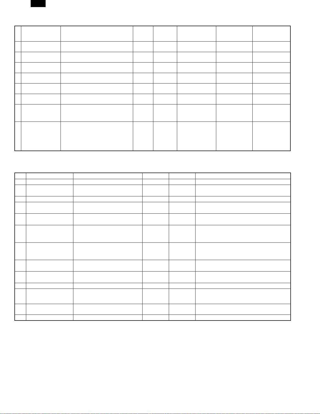
(1) Photoconductor
(11)
(1) (2) (3) (4) (5) (6) (7) (8) (9)
(1) Figure
Indicates the sensitivity of the photoconductor.
(2) (3) Alphabet
Indicates the model code. This machine’s code is PD.
(4) Figure
Indicates the end digit of the production year.
(5) Figure or X, Y, Z
Indicates the production month. X= October, Y= November,
Z= December
(6) Figure
Indicates the production lot.
(7) Figure
Indicates the sub lot division.
(8) Figure or X, Y, Z
Indicates the packing month. X= October, Y= November, Z=
December
(9) (10) Figure
Indicates the packing date.
(11) Figure or alphabet
Indicates the product name of the drum.
Effective life: 36 months from the production date (month)
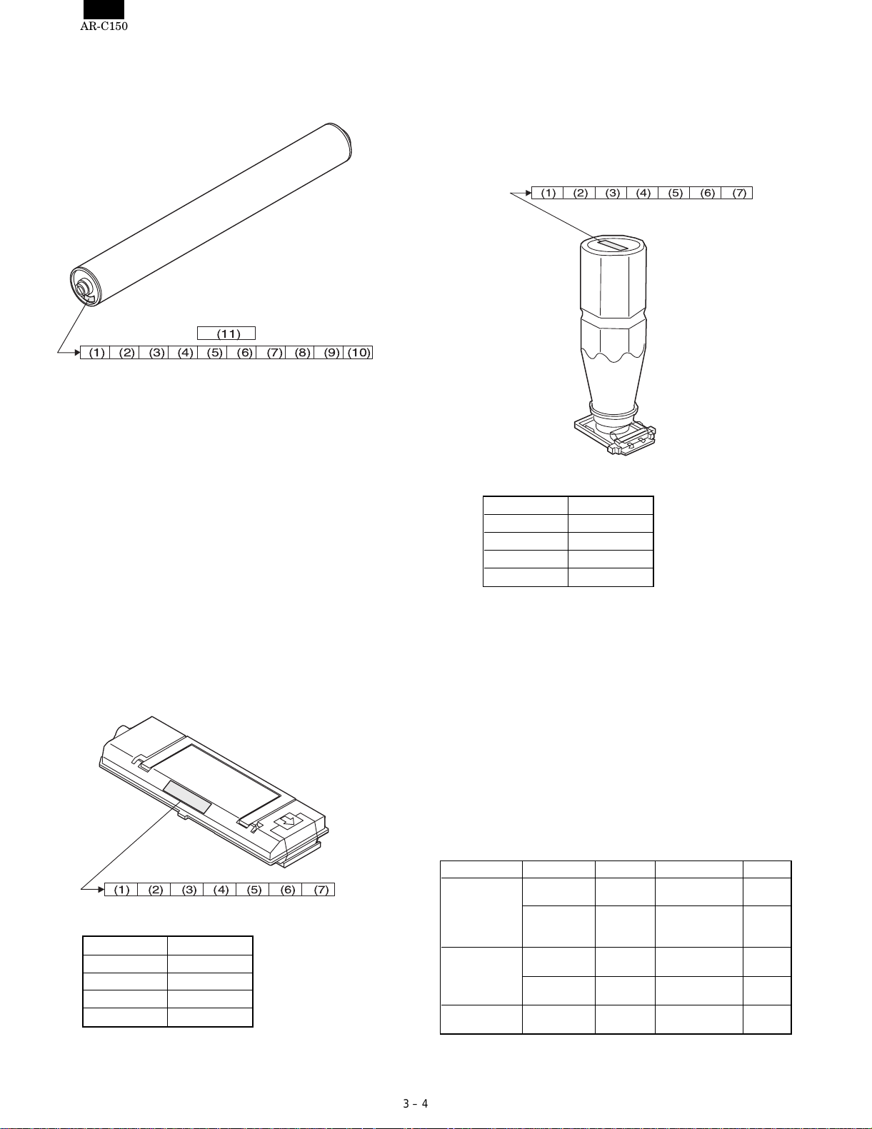
(2) Developer
(4) (5) Figure
Indicates the production date.
(6) Figure
Indicates the end digit of the production year.
(7) Alphabet
Indicates the management code. (A to Z)
Effective life: 24 months from the production date (month)
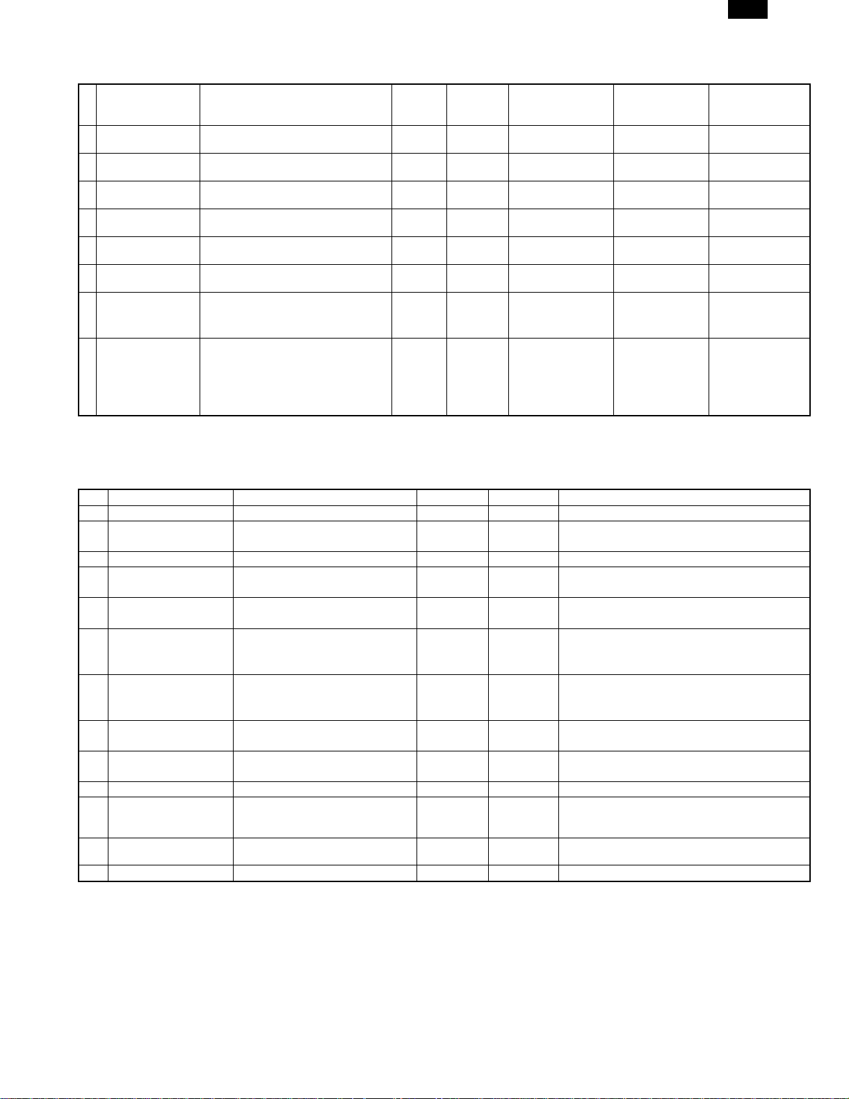
(3) Toner
(1) (2) (3) (4) (5) (6) (7)
(10)
(1) (2) Alphabet
Indicates the toner color as shown below:
Color Alphabet
Yellow RY
Magenta RM
Cyan RC
Black RK
(3) Figure, alphabet
Indicates the production month. X= October, Y= November,
Z= December
(4) (5) Figure
Indicates the production date.
(6) Figure
Indicates the end digit of the production year.
(7) Alphabet
Indicates the management code. (A to Z)
Effective life: 24 months from the production date (month)
(1) (2) (3) (4) (5) (6) (7)
(1) (2) Alphabet
Indicates the developer color as shown below:
Color Alphabet
Yellow YR
Magenta MR
Cyan CR
Black KR
(3) Figure, alphabet
Indicates the production month. X= October, Y= November,
Z= December
3. Paper
(1) Color print paper
The recommendable color print paper is shown below.
Use of the recommendable paper provides the best copy quality. The
standard paper follows it.
Kind Model Supplier Specification Note
Recommend
paper
Standard paper Necosa Necosa [11 × 8.5", 75g/m
OHP sheet
(Specified paper)
When paper of low white level is used, normal copy quality (color
reproduction) may not be obtained.
For OHP sheet, be sure to use the specified one.
3 – 4
Hammermill
LASER PRINT
Neusiedler
Color Copy
(90g/m
Igepa Igepa [A4, 80g/m
BG74.6 FOREX A4 size, 140g/m
Hammermill [11 × 8.5", 90g/m
Neusiedler [A4, 90g/m
2
)
[11 × 17", 90g/m
[A3, 90g/m
[11 × 17", 75g/m
[A3, 80g/m
2
2
2
2
2
]
2
]
]
]
2
]
2
]
]
]
2
Made by
FOREX
Page 17

AR-C150
(2) Monochrome print paper
For monochrome print, the following specifications serve as the
criteria of applicable or not.
(Values are under 20 ± 1°C, 65 ± 2%RH)
Item Standard paper Applicable paper
Weight 60 – 90g/m
Smoothness Front: ≥ 20s
Vesicularity ≥ 7s (BEEK method) Same as the left.
Untransparency ≥ 77% Same as the left.
Surface
resistance
Hardness Vertical: ≥ 17cm
Water content 4.5 % – 7.0% Same as the left.
Thickness 75µm – 110µm Same as the left.
Dimensions Standard ± 1mm (∗) Same as the left.
Back : ≥ 20s
(BEEK method)
1 × 10¹⁰ – 5 × 10¹⁰Ωcm
(20 ± 1°C, 65 ± 2%RH)
Horizontal: ≥ 13cm
(CLARK method)
2
60 – 120g/m
Front: ≥ 20s
Back : ≥ 18s
(BEEK method)
≥ 5.0 × 10⁸Ωcm
(20 ± 1°C, 65 ± 2%RH)
Same as the left.
2
(3) Print paper dimension specification
(∗)Standard dimensions are as follows:
B5 (182 ± 1 × 257 ± 1mm)
B6 (128 ± 1 × 182 ± 1mm)
A4 (210 ± 1 × 297 ± 1mm)
A5 (148 ± 1 × 210 ± 1mm)
A6 (105 ± 1 × 148 ± 1mm)
8.5" ± 5/128 × 14" ± 5/128 inch
8.5" ± 5/128 × 11" ± 5/128 inch
8.5" ± 5/128 × 8.5" ± 5/128 inch
8.5" ± 5/128 × 13" ± 5/128 inch
(Note)
(Paper which cannot be used)
The following paper cannot be used for printing.
• Paper with coated surface
• Paper with rough surface, or too smooth surface
• Documents which are separated from a pasted book
• Broken paper, folded paper, embossed paper, dry paper, wet
paper, curled paper
• Paper with metal tab or clip
• Paper with holes, cutout, or perforations
4. Environmental conditions
(1) Transit environment (sealed)
Max. change: Temperature 15°C/hour,
Relative humidity 15%RH/hour, without dew
Humidity
RH
(2) Storage environment (sealed)
Max. change: Temperature 15°C/hour,
Relative humidity 15%RH/hour, without dew
Humidity
RH
90%
40˚C, 90%
10%
-5˚C 40˚C
Temperature
Temperature (min)
Humidity
–5°C 10% 40°C 90% —
(min)
Temperature (mid)
Humidity
(mid)
Tempera-
ture (max)
Humidity
(max)
(Unsealed condition)
Humidity
RH
30˚C, 80%
80%
35˚C, 60%
20%
15˚C 35˚C
Temperature
Temperature (min)
Humidity
15°C 20% 30°C 60% 35°C 90% —
(min)
Temperature (mid)
Humidity
(mid)
Tempera-
ture (max)
Humidity
(max)
Period
Period
90%
40˚C, 90%
10%
-5˚C 40˚C
Temperature
Temperature (min)
Humidity
–5°C 10% 40°C 90% —
(min)
Temperature (mid)
Humidity
(mid)
Tempera-
ture (max)
Humidity
(max)
Period
3 – 5
Page 18
AR-C150
[4] SETUP
1. Installing (using) environment check
Before installation of the machine, check the installing (using) environment as follows:
If the installing environment does not satisfy the following conditions,
the machine may not display its performance fully, and may result in
troubles, causing safety problems. If the environment is not satisfactory, arrange it before installation and setup of the machine.
No. Content
1 Delivery space
2 Installing space
3 Power specifications (Capacity, fluctuation, safety)
4 Floor strength
5 Direct sunlight, dust, temperature, humidity, gases, chemicals
(1) Delivery space
If the door size is too small to deliver the machine in, delivery cannot
be made. Check the delivery space in advance.
(2) Installation space
Allow the following installation space around the machine for proper
operations and performances.
The space for options must be also considered.
Allow enough space at the back of the machine. If the back space is
insufficient, heat radiation and the dust proof function are prevented,
suppressing the machine performances and causing trouble.
5) Power plug
Check the shape of the power plug. Do not use a plug of different
shape.
(4) Floor strength and level
The machine is heavy, and options add further weight. Be sure to
check the floor strength for safety.
If the machine is not leveled properly, the toner concentration control
is not performed properly, affecting copy quality adversely.
It may cause color shift or image distortion.
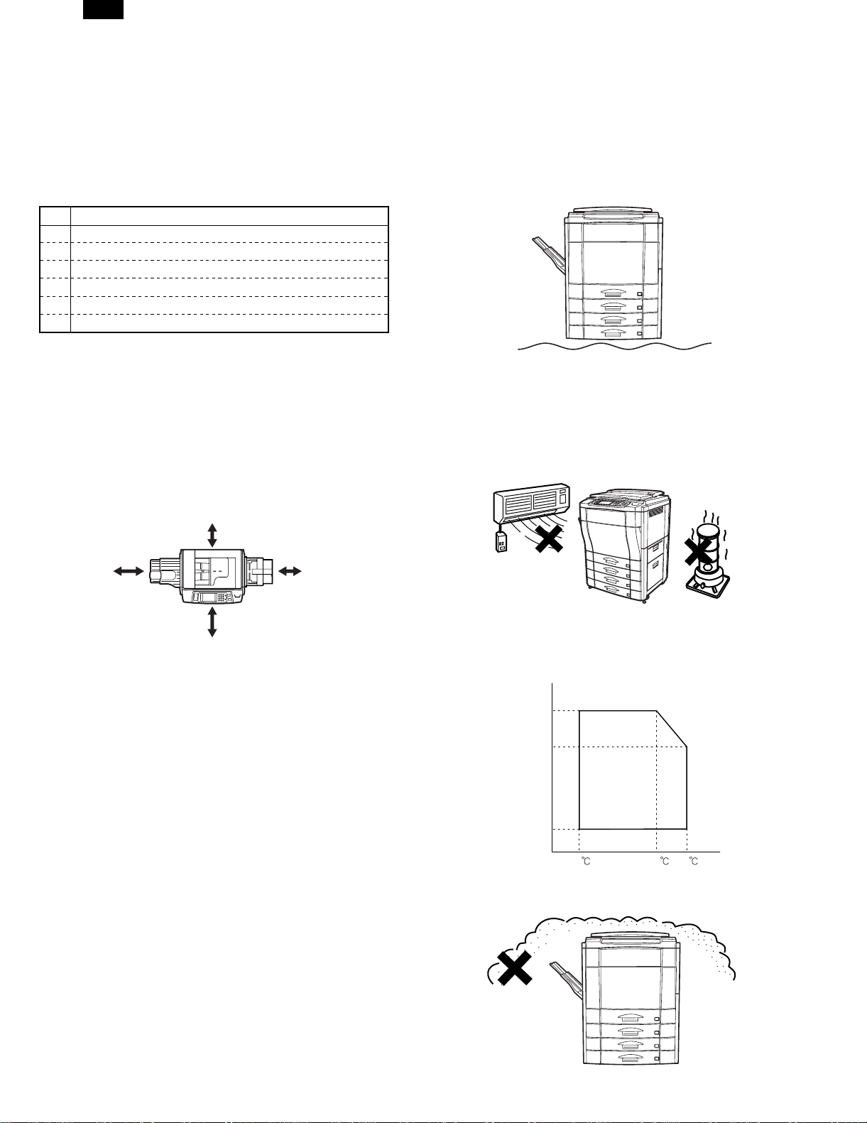
(5) Direct sunlight, dust, temperature, humidity, gases,
chemicals, vibrations
1) Temperature, humidity
The operation of this machine is assured under the following con-
ditions of storage (temperature, humidity).
Especially when the humidity is too high, paper absorbs moisture
to cause paper jams and dirty copy.
30cm
60cm
60cm
30cm
(3) Power source (capacity, voltage, frequency, safety,
plug)
If the power source requirements are not satisfied, the machine can
not display full performances, causing troubles.
Be sure to follow the instructions below.
1) Power source capacity
Check that the power capacity is enough as specified below. If is
insufficient, it must be corrected.
Current capacity
Japan: 20A or above
EX100V: 15A or above
EX200V: 10A or above
2) Power voltage
Measure the power voltage during copying to check that it is within
the range of the rated voltage ±10%.
If the voltage is not within the above range, use wider wires to
reduce impedance. (Electrical work is required.)
There is a method to use a step-up transformer. In this case, use
the transformer of greater capacity than the machine’s max. power
consumption.
3) Power frequency, waveform
The frequency fluctuation must be the specified level ±2%. If the
power waveform is distorted, trouble may be caused.
4) Safety
Be sure to ground the machine.
(Do not install near a stove, a humidifier, or a cooler.)
Do not install the copier near a heater, a cooler, or a humidifier.
If installed, the copier may form dew and cause troubles. Be careful of ventilation, too.
Humidity
85%
60%
20%
15
2) Dust
If dust enters the copier, dirty copy, paper jams, and short lifetime.
30 35
4 – 1
Page 19

AR-C150
3) Direct sunlight
If the copier is exposed to direct sunlight, the external section may
be discolored, causing poor copy quality.
4) Gases and chemicals
Do not install the copier near gases and chemicals. Especially be
careful of a diazo-type copier, which may produce ammonium gas.
The copy quality may be adversely affected, causing troubles.
3. Unpacking
A. Unpacking procedures
1 PP band 8 Bottom case unit
2 Top case 9 Accessory unit
3 Packing case 10 Paper exit tray AS
4 Skid unit 11 Accessory spacer
(AR-C100 only)
5 Top pad R 12 Accessory sleeve
6 Top pad L 13 Waste toner bottle
7 Polyethylene bag 14 Operation Manual
Unpack in the following procedures.
1) Remove the PP band.
2) Remove the top case and the packing case.
3) Remove the internal packing material and packed items.
4) Remove the machine.
1
2
5) Vibrations
Do not install machines which produce vibrations around the
copier. If vibrations are applied to the copier, copies may be
blurred and troubles may be caused.
2. Transport and installation
No. Content Method
1 Facility, equipment,
man power
2 Delivery form Transported in packed conditions.
(1) Equipment, facility, man power
It is advisable to use a forklift for efficiency and safety.
If a forklift is not available, six persons are required to move the
machine. The copier is very heavy. Consider safety in delivery and installation work.
The copier must be transported in the packed condition to the installing site (building).
(2) Delivery form
Remove the copier from the packing case outside the installing building, then carry it inside the building.
Use a forklift. (If a forklift is not available,
4 persons are required to install.)
3
4
4 – 2
Page 20

AR-C150
B. Consumable parts required for setup
2
3
No. Name Outside Japan Japan
1 Oil bottle AR-C15SL Starter kit
2 Developer cartridge (Y)
3 Developer cartridge (M)
4 Developer cartridge (C)
5 Developer cartridge (K)
6 Developing unit AR-DW1
Toner Y, M, C, K Y, M, C, K
Color developer kit
(Y, M, C)
Black developer (K)
(Developing unit × 4)
(AR-C10SK)
1
2
3
6
5
5
4
7
6
9
8
6
13
4
14
10
11
12
4 – 3
Page 21

AR-C150
C. Accessories
AR-C100
OPC drum × 4 pcs (∗2)
Toner collection container × 2 pcs (∗1)
Toner collection container for transfer belt (∗2)
Original cover (2-step folding type)
Paper exit tray (Small-space)
Operation Manual
Delivery/Installation report
Counter contract
Maintenance card
Maintenance sheet
Polyethylene sheet
Polyethylene gloves
Polyethylene bag
Note for forgery inhibition label (Attached to the machine.)
∗1: One of two toner collection containers is installed to the machine
when shipping.
AR-C150 (For Japan)
OPC drum × 4 pcs (∗2)
Toner collection container × 2 pcs. (∗1)
Toner collection container for transfer belt (∗2)
Original cover
Paper exit tray
Operation Manual
Key operator guide
Delivery/Installation Report
Counter contract
Maintenance card
Maintenance sheet
Polyethylene sheet
Polyethylene gloves
Polyethylene bag
Copy inhibition label (Attached to the machine.)
∗2: T he tone r colle ction contain er for t he tr ansfer belt and the OP C
drum are attached to the machine when shipping.
AR-C150 (Outside Japan)
Accessories for each destination (Outside Japan)
Destination USA Canada Germany U.K. Other Europe Australia Others
OPC drum × 4 pcs Installed when
Toner collecting
container × 2
Toner collection
container for transfer belt
Original cover Option Option Option Option Option Option Option
Paper exit tray ❍❍❍❍❍❍❍
Installed language ROM
(Default)
(Installed language)
Set with SIM 26-22.
Key sheet English English/French German/English English None
Paper tray size display
sheet
Operation Manual English English/French German/English English None
Delivery and installation
report
Maintenance card ❍❍❍❍❍❍❍
Maintenance sheet ❍❍❍❍❍❍❍
Polyethylene sheet ❍❍❍❍❍❍❍
Polyethylene gloves ❍❍❍❍❍❍❍
Polyethylene bags ❍❍❍❍❍❍❍
MSDS card ❍❍✕❍✕✕✕
SCA warranty card ✕✕✕✕✕❍✕
Copy inhibition label ✕❍✕✕✕✕✕
Warranty registration ✕✕✕❍✕✕✕
∗1
shipping
Installed when
shipping
Installed when
shipping
English English German English English English English
German German English German German German German
French French French French French French French
Spanish Spanish Spanish Spanish Spanish Spanish Spanish
Italian Italian Italian Italian Italian Italian Italian
Dutch Dutch Dutch Dutch Dutch Dutch Dutch
Swedish Swedish Swedish Swedish Swedish Swedish Swedish
Japanese Japanese Japanese Japanese Japanese Japanese Japanese
Inch series × 3 Inch series × 3 AB series × 3 AB series × 3 AB series × 3 AB series × 3 AB series × 3
✕✕❍✕❍❍✕
Installed when
shipping
Installed when
shipping
Installed when
shipping
Installed when
shipping
Installed when
shipping
Installed when
shipping
Installed when
shipping
Installed when
shipping
Installed when
shipping
Installed when
shipping
Installed when
shipping
Installed when
shipping
Installed when
shipping
Installed when
shipping
Installed when
shipping
∗2 English English
∗3 English English (Some
Installed when
shipping
Installed when
shipping
Installed when
shipping
areas:
Arabic/Russia)
∗1: One of two toner collection containers is installed to the machine when shipping. The installed one has no cap.
∗2: The Key sheet for Europe is included in the Operation Manual Kit.
∗3: The Operation Manual and the key operator guide are separate for Japan and USA. For the other destinations, they are bound together into
one.
4 – 4
Page 22

AR-C150
Operation Manual kit
Language Model name Content Note
English AR-150SE Operation Manual (Bound
Germany AR-150SG
French AR-150SF
Spanish AR-150SS
Italian AR-150SI
Dutch AR-150SH
Swedish AR-150SW
together with Key Operator
Guide), Operation panel
sheet
25 sets
4. Lock release
1
A. External fitting section
1) Remove the fixing tape and packing material from the copier body.
[Paper exit side] [Paper feed side]
2
4
No. Parts name
1 No. 2/3 mirror base lock screw
2 Belt unit fixing screw B
3 Tray rotating plate fixing material
4 Fusing, transfer unit fixing screw A
5 Paper guide lock screw
3
B. Scanner section
1) Release the No. 2/3 mirror unit lock.
(Remove the fixing screw, washer, and note label of No. 2/3 mirror
unit on the left side.)
4 – 5
Page 23

AR-C150
C. Transfer section
1) Open the front cover (1), and remove the toner hopper unit (2).
2) Remove the toner hopper connector cover (3) in section A and
remove the connector (4).
2
A
1
4) Loosen the blue screw (1), and remove the process frame cover
(2).
2
1
5) Remove the unit fixing screw (1), and hold the lever (2) to remove.
A
B
3
3
4
3) Remove the blue screw (1), and remove the toner hopper unit (2).
2
1
6) Loosen the blue screw (1), and remove the fusing front cover (2)
in the arrow direction.
2
1
2
1
4 – 6
1
Page 24

AR-C150
7) Remove the unit fixing screw B (1) and the unit fixing screw A (2).
1
2
8) Remove the fusing front paper guide fixing screw (1) and the
protector (2).
Keep the removed screw in the screw hole in the transfer section.
When in transit of the machine, fix the fusing front paper guide
with this screw.
E. Paper feed, paper transport section
1) Remove the rotating plate fixing material of the paper feed tray,
and remove the caution label.
5. Cleaning
A. Main charger
1) Open the front cover.
2) Remove the toner hopper unit.
3) Remove the process frame cover.
4) Press the main charger unit hook section and releaser the lock.
Remove the main charger unit (1) from the copier.
D. Fusing and paper exit section
1) Insert and press the front side shaft (1) with a screwdriver.
2) Insert and press the rear side shaft (2) with a screwdriver.
2
1
5) Remove the electrode section fixing screw (2) of the main charger
unit (1), and remove the electrode section (3).
3
2
1
1
6) Clean the tip of the electrode by pushing the electrode cleaner
through it. (Repeat 2 or 3 times.)
(Note) Do not move the cleaner when it is pushed through the
cleaner. When cleaning, clean the whole area evenly.
4 – 7
Page 25

AR-C150
7) Install the electrode section to the original position, and fix it with
the fixing screw.
8) Insert the main charger unit fully into the machine along the copier
guide.
B. Document table
(1) Document table cleaning
If the document table is dirty, the dirt is copied.
Wipe and clean with soft cloth with water, then wipe with dry cloth.
6. Consumable parts setup
A. Fusing oil setup
1) Remove the cap (1) from the oil bottle (2), and remove the inner
cap. Set the cap (3) again.
1
3
2
2) Remove the oil tank cover (1) from the oil tank, and fill oil from the
oil tank (2).
1
2
1
2
(2) Document cover cleaning
If the document cover is dirty, the copy is dirtied or the document size
is erroneously detected.
Wipe and clean with soft cloth with water, then wipe with dry cloth.
(Note) • If the dirt cannot be removed easily, wipe with soft cloth im-
mersed in water or neutral detergent, then wipe with dry
cloth.
• Do not use benzene or thinner for cleaning, which may
change the parts in quality or discolor.
(Note) Do not exceed line A when filling oil.
(Fusing oil handling)
(1) Print operation check procedure without filling oil in
the oil tank
1) Remove the fusing oil applying section cover.
2) Supply 10 – 15cc of fusing oil all over the oil pipe and the oil
blade. Use of fusing oil YYOK-0059FC31 (15cc) is advisable.
This allows to print about 100 pages.
4 – 8
Page 26

)
AR-C150
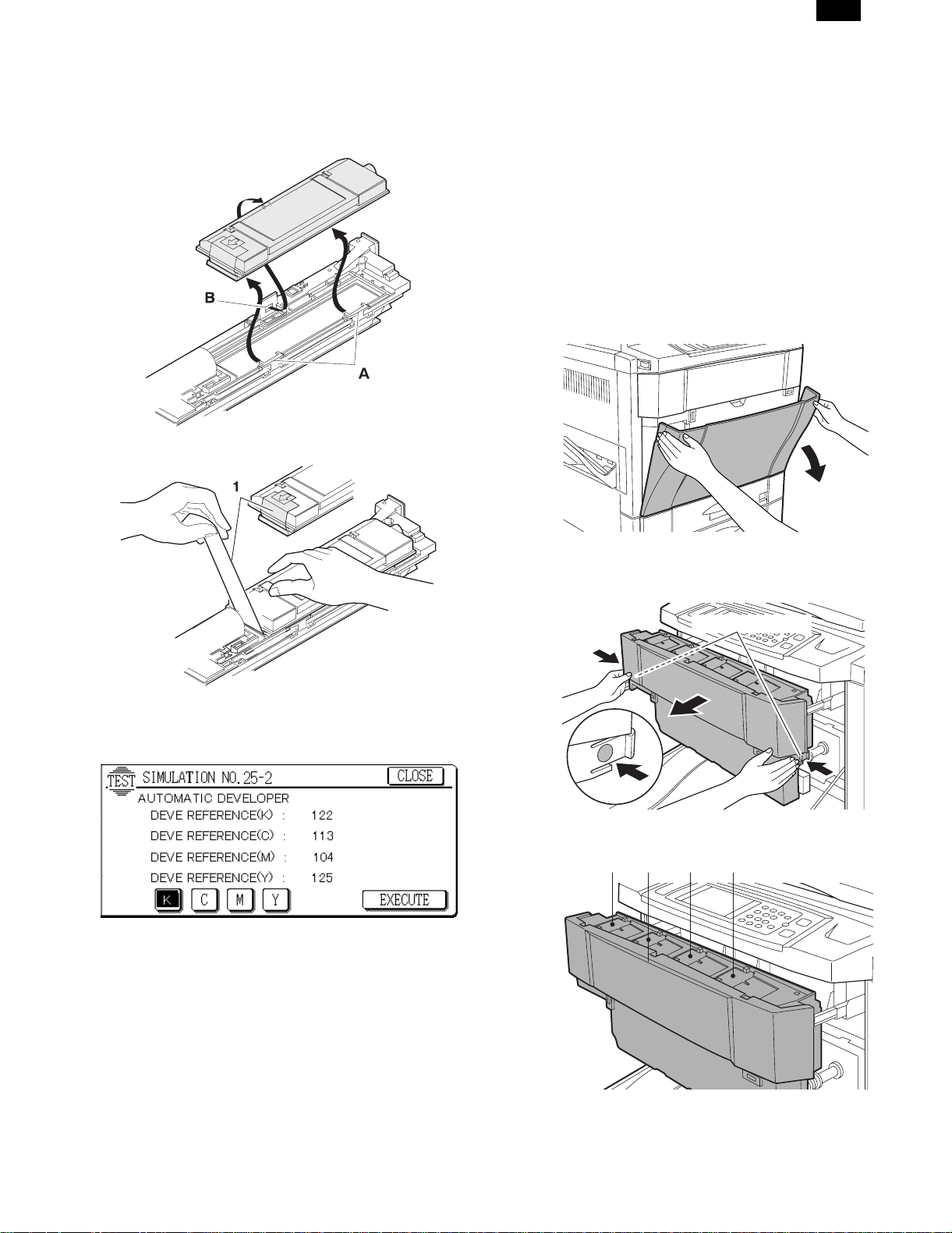
B. Developer setup
(1) Developer setup
1) Remove the blue screw (1), and remove the DSD holder
(2)(3)(4)(5).
5
4
3
2
1
(Note) A color label is attached to each DSD holder for identification
of the color. When installing the DSD holders, be sure to
match the label color with the color on the machine.
2) Remove the special tool (2) from the back of the process cover
(1).
4) Pull out the transfer unit, cover the whole surface of the transfer
belt with paper, and insert the transfer unit. At that time, keep
the lock handle released. This procedure is performed in order to
prevent against dirt by toner dropped from the process frame
unit.
5) Remove the connector (1) and loosen the blue screw (2).
1
2
2
1
3) Fix the drum holder (4) with the special tool (2), and remove the
blue screw (3).
2
6) Remove the process frame unit from the arrow section.
7) Set the developer units in the sequence of (1) to (4).
(Note) Insert section A into the hole along the arrow indication.
Fit the projection B with the hole in the developer unit, and
connect the connector C.
Set each developer unit to its position. Be careful not to mistake the position.
4 (Y)
3 (M)
2 (C)
A
1 (K
4
4
3
4 – 9
Page 27
AR-C150
8) Set the developer cartridges in the sequence of black, cyan,
magenta, and yellow.
9) Put the developer cartridge on the developer unit pawl A, and
press is until pawl P clicks.
(Note) Check that the developer color and the developer unit color
are the same.
10) Pull out the developer cartridge film sheet (1). (4 positions for
each color)
5) Clear the developer counter with SIM 24-5.
6) Execute SIM 44-27 to reset the half tone correction data (correction conditions) to the default level.
(Note) 1) The developers of yellow, magenta, and cyan must be
replaced at a time.
If individual developer is replaced, color balance is changed
and cannot be adjusted.
The black developer can be replaced individually.
2) After replacement of the developers and the photoconductor, execute SIM 44-27 to reset the half tone correction data
(correction conditions) to the default level.
If the above procedure is missed, half tone correction may
not be performed properly.
3) Reset the developer counter with SIM 24-5.
C. Toner setup
1) Open the front cover.
(After completion of the above procedures, attach the removed cover
and the cabinet.)
(2) Toner concentration reference control level setup
1) Enter SIM 25-2 mode with the front cabinet open.
2) Close the front cabinet.
3) Select the developing unit to be adjusted. (Select the all.)
4) Press the EXECUTE key and it is highlighted. The OPC drum
motor rotates and the toner concentration sensor detects toner
concentration and the output value is displayed.
After 3 minutes of stirring, the average value of the toner concentration sensor detection level is set (stored) as the reference
toner concentration control value.
(Note) If the adjustment is stopped within 3 minutes, the setup result
is not stored.
When the EXECUTE key is pressed during operation, it is
stopped and the EXECUTE key returns to the normal display.
If "EE-EU" or "EE-EL" is displayed, the reference toner concentration control value is not set normally.
EE-EL: The value is less than 79 (1.59V).
EE-EU: The value is over 177 (3.41V).
2) Remove the toner box.
3) Press the lock release buttons on the both sides to release lock
and pull the toner box out.
Lock release buttons
4) The toner supply ports on the toner box are arranged as shown
below.
KCMY
4 – 10
Page 28

AR-C150
5) Tap the toner cartridge top 5 times, and shake it horizontally 20
times.
5 times
20 times
6) Attach the toner cartridge to the toner box to be refilled.
(Example) When refilling yellow toner:
Securely insert two projections of the toner cartridge into
the toner supply port.
Be sure to check the color.
The toner cartridge must be attached to the toner supply port of
the same color.
7) Move the toner cartridge in the arrow direction until it stops.
11) Tap the toner cartridge top several times.
12) Drop the toner attached to the inside of the toner cartridge completely.
13) Move the empty toner cartridge in the arrow direction and
remove it.
14) Insert the toner box into the original position.
8) Remove the seal.
9) Hold the toner cartridge and remove the seal.
10) It takes about 40 sec to supply toner in the toner cartridge to the
toner box.
15) Close the front cover.
4 – 11
Page 29
AR-C150
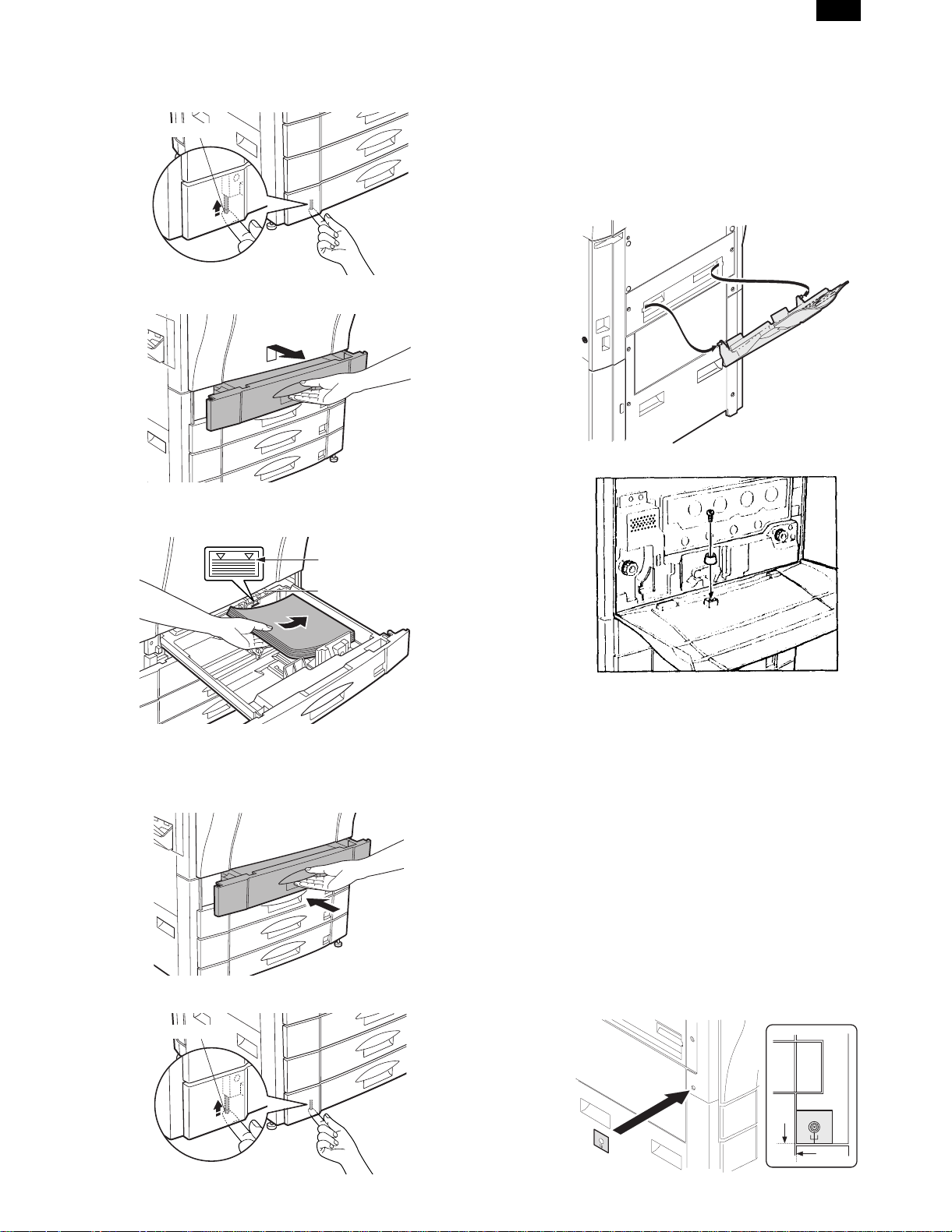
D. Paper setup
1) Push down the lock lever until it stops to release the tray lock.
(AR-C100 only)
Lock lever
2) Lift the grip upward, and pull out the paper tray slowly until it
stops.
3) Set the paper below the indication line.
At that time, set the paper size detection lever according to the set
paper size.
(Note) • When a tray is pulled out during copying, a paper jam may
occur. When a paper jam occurs in the tray, if the tray is
pulled out, the jammed paper may be torn.
• Be sure to lock the tray after supplying paper in order to
prevent the copy user from pulling out the tray carelessly.
(AR-C100 only).
7. Parts setup
(1) Paper exit tray setup
(2) Front cabinet stopper setup
Indication line
Paper size detection lever
(Note) • Curled paper, folded paper or copied paper may cause
paper jams.
• When pulling out the tray, do not put a heavy thing on it or
do not press it.
4) Push the tray into the machine slowly and securely.
5) Push up the lock lever until it stops to lock the tray. (AR-C100
only)
Lock lever
(3) Horizontal level check and adjustment
If the copier is tilted back and forth, the following troubles may be
caused.
• Oil leak from the fusing section
• Image distortion and color image resist
To avoid the above troubles, check the horizontal level of the copier
back and forth and adjust if necessary. A small tilt in left and right
direction is allowed due to the margins.
a. Necessary tools
• Horizontal level check sheet (UKOG-0286FCZZ)
• Screw (LX-BZ0870FCZZ)
4 lock release/C transfer section/Use screws other than the screws
removed in Procedure 7).
• Horizontal level check string (with washer) (UKOG-0285FCZZ)
• Spacer disk (UKOG-0287FCZZ)
• Spacer (UKOG-0288FCZZ)
b. Check and adjustment
1) Paste and attach the horizontal level check sheet to the edge of
the cabinet.
(AR-C100 only)
4 – 12
Page 30

AR-C150
2) Remove the cabinet fixing screw.
3) Pass the washer of the horizontal level check string into the screw
(LX-BZ0870FCZZ) and attach it to the copier.
4) Check that the horizontal level check string is in the frame mark of
the horizontal level check sheet. If the horizontal check sheet is
not available, check that the horizontal level check string is within
the cabinet fixing screw width.
If the above condition is satisfied, no need to make further adjustment.
If the above condition is not satisfied, perform the following procedure.
5) Put the spacer disk under the caster.
If the adjustment cannot be performed only with the spacer disk,
use the spacer together.
(4) Adjuster setup
1) As shown in the figure below, turn the adjuster until it makes contact with the floor securely.
Lock
Adjuster
Release
8. Copy quality check
Check the following items. For the adjustment and check procedures,
refer to the section of adjustments.
(1) Focus (resolution) (Refer to ADJ M12.)
(2) Copy image off- and center (Refer to ADJ M14 and
ADJ M15.)
(3) Image loss, void area (Refer to ADJ M16.)
(4) Image resist
Check the following items. If the adjustment is improper, make an adjustment again.
∗ Main scanning direction image resist adjustment (Refer to ADJ
M9.)
∗ Sub scanning direction image resist adjustment (Refer to ADJ
M10.)
(5) Copy color balance, density (Refer to ADJ M17.)
There are two check methods.
∗ Set the color balance (copy density) setup of each copy mode to
the center. Make a copy of the gray scale chart (UKOG0162FCZZ) and a copy of the color test chart (UKOG-0283FCZZ).
Check that the color balance and the density level are within the
specified range.
For details and the judgement criteria, refer to "Copy mode color
balance and density check" in ADJ M17.
4 – 13
Page 31

AR-C150
∗ Perform procedure 1) of ADJ M17 ADJ 3 in the adjustment section
to check the color balance and the density level.
(Note) When performing checking only, do not change the adjust-
ment value.
For details and the judgement criteria, refer to ADJ M17
ADJ3.
If the color balance and the density level are not within the specified
range, make an adjustment according to the flowchart of ADJ M17.
9. Specification setup
Execute SIM 26 to set the specifications according to the customer’s
need.
Sim No. Content
26 1 Used to set options. (When installing an option, use this
simulation to set the option (software). (AR-C150 only)
2 1) Used to set the paper size of the large capacity tray.
(When the paper size is changed, this simulation must
be executed to change the paper size in software.)
2) Used to detect 8.5 × 13" size paper and documents
and to set the display mode. (All paper feed modes)
3) Used to set the paper size in the manual paper feed
mode. (AR-C150 only)
3 Used to set the auditor specification mode. Setting must
be made according to the use conditions of the auditor.
5 Used to set the count mode of the total counter, the
developer counter, and the maintenance counter.
6 1) Used to set the specifications (paper, fixed copy
magnification ratio, machine operations at an image
(process) correction error) depending on the destination.
2) Used to set the user logo. (AR-C100 only)
15 Used to set the fusing operation mode (paper curl
prevention mode).
18 Used to set Enable/Disable of the toner save operation.
(The function of this simulation is effective only in Japan
and UK version. (Depending on the setting of SIM 6-6
(Destination).) For the other destinations, the same
setting can be made with the user program P22.
(AR-C150 only)
22 Used to set the destination specifications (language
display). (AR-C150 only)
28 Used to set the AC power voltage. (For the fusing
section heater lamp power control)
30 Used to set the CE mark complying operation mode.
(Soft start when driving the fusing heater lamp.)
35 Used to set whether the trouble history display of SIM
22-4 is displayed as one time trouble or continuous
troubles when the same trouble repeatedly occurred.
45 Used to set the coy fee. (AR-C100 only)
Check item Note
Group mode copy When RADF is
installed
Staple When RADF is
installed
AR-C150
only
AR-C150
only
11. Recording of setup and adjustment
data
Execute SIM 22-6 to print and keep the various setup data and the
adjustment data (list).
In case of memory trouble, when the PCU PWB or the ICU PWB is
replaced, if there is not the above information, all adjustment must be
made from the beginning.
With the record of the above information, the setup data and the adjustment data can be directly inputted efficiently.
12. Procedures for transit
When moving the copier, the following procedures must be performed.
(1) Remove paper from the paper trays.
(2) Remove the developing unit from the copier.
(3) Lock all the locks again.
(4) Remove the fusing unit.
(5) Remove the fusing oil bottle.
After removing the fusing unit, perform the following procedures.
1) Remove the fusing oil bottle cover.
2) Attach the caps (which are appended to the fusing oil bottle) to the
three holes in the fusing oil bottle.
10. Function and operation check
Check the following operations.
Check item Note
Paper feed operation
(manual paper feed)
Paper feed by the paper
tray
Paper feed by the large
capacity paper feed tray
Paper size detection
Document size detection
RADF copy (S-S mode) When RADF is
RADF copy (S-D mode) When RADF is
RADF copy (D-D mode) When RADF is
RADF copy (D-S mode) When RADF is
Sort mode copy When RADF is
When the large
capacity tray is
installed.
installed.
installed
installed
installed
installed.
When the duplex
unit is installed.
When the duplex
unit is installed.
AR-C150
only
AR-C150
only
AR-C150
only
AR-C150
only
AR-C150
only
AR-C150
only
AR-C150
only
3) Remove the fusing oil bottle from the copier.
4 – 14
Page 32

AR-C150
[5] EXTERNAL VIEW AND INTERNAL STRUCTURE
1. List
2. Contents
A. External view and operation parts
(1) External view and external operation parts
32145
67 8910
11 1312 14 15
No.
1 Waste toner bottle Collect waste toner from the image process section.
2 Paper exit tray Receives printed paper.
3 Main power switch Turns on/off the power.
4 Toner hopper cover Toner container section
5 Operation panel Used to perform various setups, displays, and simulations.
6 Original stacker Stacks originals.
7 Original cover Presses an original and prevents against leakage of light from the scanner lamp.
8 Original table An original to be scanned is set on this table. (Left edge reference)
9 Paper clips tray Used to put paper clips on it.
10 Dehumidifier heater switch Switch of the dehumidifier for paper Standard in Japan only
11 Paper tray/duplex module
installing section
12 Front cover This cover is opened to remove and install the photoconductor cartridge, the
13 Paper tray Used to set paper on it.
14 Right doors These doors are opened to remove jammed paper from the paper transport section.
15 Manual feed tray In manual paper feed copy, inset paper from this tray.
Name Function and operation
Either of the following two options can be connected:
Duplex module (option) which allows automatic duplex copy.
Paper tray module (option)
developer cartridge, the transfer unit, and the fusing unit, and remove jam paper.
Parts
Note
5 – 1
Page 33

(2) Internal operation parts
AR-C150
21
3
No.
546
Parts
Name Function and operation
1 Fusing roller rotation knob Turn this knob to remove jammed paper from the fusing section.
2 Toner hopper Stores toner of Black, Cyan, Magenta, and Yellow.
3 Transfer belt Transfers toner image on the photoconductor to the paper
4 Lift-up lever Used to lift up and down the transfer unit.
(Used when pulling out and installing the transfer unit.)
5 Heat roller Fuses toner image on the paper by heat and pressure.
6 Paper exit transport guide Opened to remove jammed paper from the fusing section.
(3) Operation, display parts
12 13 1 2 3 4
INFORMATION
CUSTOM
SETTINGS
DATA
PRINT
ON LINE
SPECIAL
MODES
2-SIDED
COPY
11
COPY
OUTPUT
10
12
3
456
789
AUDIT
PROGRAM
0
P
INTERRUPT
CLEAR
ALL
C
CLEAR
Note
8
CA
9
No.
Name Function and operation
Parts
1 Touch panel Used to display various information and make various setups.
2 10-key Used to enter set values.
3 Interruption key Used to interrupt during multi copy.
4 Clear all key Used to reset all setups to the default values.
5 – 2
765
Note
Page 34

AR-C150
No.
5 Auditor key Used to use the internal auditor.
6 Program key Used to program copy conditions.
7 Clear key Used to clear set items and cancel multi copy operation.
8 Start key/lamp for color
copy
9 Start key/lamp for
black/white copy
10 Copy mode key/lamp Used in the copy mode. When the machine is set to copy mode, the lamp is lighted.
11 Printer mode key/lamp Used in the printer mode. When the machine is set to copy mode, the lamp is lighted.
12 Data lamp Blinks when data is received from the print server.
13 Online lamp Lights when communication with the print server is enabled.
Name Function and operation
Used to start color copy or monochrome copy. (When the machine is ready to copy, the
lamp in the start key is lighted.)
Used to start black/white copy. (When the machine is ready to copy, the lamp in the start
key is lighted.)
Parts
Operation, display parts
1
2 3 4 5 67
19
18
17
SPECIAL
MODES
2-SIDED
COPY
OUTPUT
READY TO COPY.
1
1.
8
11
2
2.
1711
1
3.
8
14
2
AUTO
1
AUTO 8/ 11
2
EXPOSURE PAPER SELECT
ORIGINAL
1
8
11R
2
1
8
2
100%
COPY RATIO
11
INFORMATION
CUSTOM
SETTINGS
Note
8
9
13 1215 1416
No.
1 Select paper tray display section Displays the selected paper tray.
2 Paper size display section Displays the paper size.
3 Paper remaining quantity display section Displays the paper quantity.
4 Manual feed tray display section When the manual feed tray is selected, this display becomes active.
5 Manual feed paper size display section Displays the paper size.
6 Copy quantity display Displays the copy quantity to be made.
7 Original size display section Displays the original size.
8 Operation guide key Used to display descriptions on functions and operations.
9 User setup key Used to set the key operator program.
10 Copy magnification ratio key Used to set the copy magnification ratio.
11 Magnification ratio display section Displays the currently set copy magnification ratio.
12 Paper size display section Displays the selected paper size.
13 Paper size select key Used to select the paper size.
14 Paper size display section Displays the paper size.
15 Copy density key Used to set the copy density.
16 Copy density display section Displays the copy mode, and the copy density level.
17 Output key Used to set the finishing mode.
18 Duplex mode key Used to set the duplex copy functions.
19 Special function key Used to set special functions.
Name Function and operation
Parts
11
10
Note
5 – 3
Page 35

B. Internal parts
(1) Cross section
12 34 5 6 7 8 9
AR-C150
10
11
12
13
14
15
16
74
75
71
17
18
20
19
21
22
23
24
25
26
27
28
29
30
31
32
33
34
35
36
37
38
No.
67
66
65
64
63
62
61
60
59
58
57
56
55
54
53
52
51
50
Parts
Name Function and operation
3940414243444546474849
1 No. 2 mirror Sends the original image to No. 3 mirror.
2 No. 3 mirror Send the original image to the CCD.
3 Y-LSU unit Converts yellow components of image signals sent from the ICU PWB into laser
beams, and radiates the beams onto the OPC drum.
4 M-LSU unit Converts magenta components of image signals sent from the ICU PWB into laser
beams, and radiates the beams onto the OPC drum.
5 No. 1 mirror Sends the original image to No. 2 mirror.
6 Scanner lamp Radiates light to the CCD for scanning the original image.
7 CCD lens Reduces the original image (light) and project it to the CCD.
8 C-LSU unit Converts cyan components of image signals sent from the ICU PWB into laser
beams, and radiates the beams onto the OPC drum.
9 CCD PWB Reads the original image and converts it into electrical signals.
10 K-LSU unit Converts black components of image signals sent from the ICU PWB into laser
beams, and radiates the beams onto the OPC drum.
11 Developing roller (Y) Attaches toner on the OPC drum. (Y)
12 Developing roller (M) Attaches toner on the OPC drum. (M)
13 Developing roller (C) Attaches toner on the OPC drum. (C)
14 Developing roller (K) Attaches toner on the OPC drum. (K)
15 Upper resist roller Transports paper to the transfer section.
16 Lower resist roller Transports paper to the transfer section.
17 Paper transport roller 1 Transports paper to the transfer resist roller.
18 Idle roller Applies pressure to paper and the transport roller.
19 Idle roller Prevents against paper skew.
20 Paper transport roller 1 Transports paper to the transfer section (transfer resist roller).
72
69
70
73
68
Note
5 – 4
Page 36

AR-C150
No.
21 Paper feed tray (No. 1
paper tray)
22 Separation roller (No. 1
paper tray)
23 Paper pickup roller (No.
1 paper tray)
24 Idle roller Applies pressure to paper and the transport roller.
25 Paper transport roller 2 Transports paper to the transport roller 1.
26 Paper feed roller (No. 2
paper roller)
27 Separation roller (No. 2
paper tray)
28 Paper pickup roller (No.
2 paper tray)
29 Idle roller Applies pressure to paper and the transport roller.
30 Paper transport roller 3 Transports paper to the transport roller 2.
31 Paper feed roller (No. 3
paper tray)
32 Separation roller (No. 3
paper tray)
33 Paper pickup roller (No.
3 paper tray)
34 Idle roller Applies pressure to paper and the transport roller.
35 Paper transport roller 4 Transports paper to the transport roller 3.
36 Paper feed roller (No. 4
paper tray)
37 Separation roller (No. 4
paper tray)
38 Paper pickup roller (No.
4 paper tray)
39 Transfer roller (K) Applies a transfer voltage to the transfer belt.
40 OPC drum unit (K) Forms black latent electrostatic images.
41 Main charger unit (K) Charges the black OPC drum negatively.
42 OPC drum unit (C) Forms cyan latent electrostatic images.
43 Transfer roller (C) Applies a transfer voltage to the transfer belt.
44 Main charger unit (C) Charges the cyan OPC drum negatively.
45 OPC drum unit (M) Forms magenta latent electrostatic images.
46 Transfer roller (M) Applies a transfer voltage to the transfer belt.
47 Main charger unit (M) Charges the magenta OPC drum negatively.
48 OPC drum unit (Y) Forms yellow latent electrostatic images.
49 Transfer roller (Y) Applies a transfer voltage to the transfer belt.
50 Main charger unit (Y) Charges the yellow OPC drum negatively.
51 Transfer belt Transfers toner images on the OPC drum to paper.
52 Waste toner bottle Collects waste toner.
53 Oil tank Stores oil.
54 Lower heater lamp Heats the lower heat roller.
55 Lower heat roller Applies a pressure and heat to toner and fuses it to paper.
56 Lower separation pawl Separates paper mechanically from the lower heat roller. Not required for AR-C100
57 Fusing transport roller Transports paper to the paper exit roller.
58 ADU gate Switches the paper route in the duplex mode.
59 Paper exit roller Discharges paper outside the machine.
60 Idle roller Applies pressure to paper and the paper exit roller.
61 Idle roller Applies pressure to paper and the transport roller.
62 Upper cleaning roller Cleans the fusing roller.
63 Upper heat roller Applies a pressure and heat to toner and fuses it to paper.
64 Upper heat lamp Heats the upper heat roller.
Name Function and operation
Feeds paper to the paper transport section.
Separates paper and transport it to the paper transport section.
Sends paper to the paper feed roller.
Feeds paper to the paper transport section.
Separates paper and prevents against double feed.
Sends paper to the paper feed roller.
Feeds paper to the paper transport section.
Separates paper and prevents against double feed.
Feeds paper to the paper feed roller.
Feeds paper to the paper transport section.
Separates paper and prevents against double feed.
Sends paper to the paper feed roller.
Parts
Note
because paper size is
limited.
5 – 5
Page 37

AR-C150
No.
Name Function and operation
Parts
Note
65 Oil roller Applies oil to the upper heat roller.
66 Oil blade Controls oil quantity on the oil roller to be even.
67 Separation pawl Separates paper from the transfer belt mechanically.
68 Waste toner bottle Collects waste toner from transfer belt.
69 Paper pickup roller Sends paper to the paper feed roller. Manual paper feed section
70 Paper pickup solenoid Presses paper onto the paper pickup roller.
71 Manual paper feed roller Feeds paper to the paper transport section.
72 Manual paper feed clutch Transmits the paper feed drive motor power to the manual paper feed unit.
(Controls ON/OFF of the manual paper feed unit.)
73 Separation roller Separates paper to prevent against double feed.
74 Manual transport roller Applies a pressure to paper and the transport roller to give the transport roller
power to the paper.
75 Idle roller Applies a pressure to paper and the transport roller and gives a transport power of
the transport roller to the paper.
(2) Operation section
1
2
3
4
5
7
Parts
No.
Code
Signal
name
Name Type Function/Operation
1 Operation UN Displays various information and makes setups.
2 MAIN SW Main switch Rocker switch Turns on/off the main power.
3 Operation PWB L Outputs key operation signals.
4 OP control PWB Controls the whole operation unit. (Displays
information from PCU PWB and sends
operational information to PCU PWB.)
5 Operation PWB R Outputs key operation signals.
6 LCD back light
Drives the LCD back light.
inverter PWB
7 LCD LCD Displays various information. Functions as a key.
6
Active
Note
condition
5 – 6
Page 38

AR-C150
(3) Paper feed, transport section
Right door
Paper tray
a. Paper tray
1
Paper feed unit
Vertical paper transport
upper
Right door lower
Vertical paper transport
lower
4
3
2
9
8
Lift-up unit
5
6
7
Parts
No.
Code
Signal
name
Name Type Function/Operation
1 Paper trays Stores print paper.
2 Paper position (longitudinal
direction) adjustment plate lock lever
3 Paper position (longitudinal
Locks or releases the paper position
(longitudinal direction) adjustment plate.
Positions paper (longitudinal direction).
direction) adjustment plate
4 Lift plate Lifts up paper to press it onto the pickup
roller.
5 Paper position (traverse direction)
Positions paper (traverse direction).
adjustment plate
6 Paper size set block Makes the paper size detector detect the
paper size.
7 Lift gear Transmits the lift motor power to the lift plate.
8 Paper size display plate Displays the paper size.
9 Paper position (traverse direction)
adjustment plate lock lever
Locks or releases the paper position
(traverse direction) adjustment plate.
Active
condition
Note
5 – 7
Page 39

b. Paper tray lift unit
AR-C150
3
4
2
1
5
6
Parts
No.
Code
Signal
name
Name Type Function/Operation
Active
condition
Note
1 Paper tray lift unit Drives the paper tray lift plate.
2 Paper size
detection actuator
3 Paper tray lift unit
Transmits protrusion pattern of the paper
size set block to the paper size detector.
Controls the paper tray lift unit.
control PWB
4 LUMx LUMx Lift motor Synchronous motor Drives the lift plate. The numbering is
made in the sequence
of 1 - 4 from the top to
the bottom.
5 CxSSx CxSSx Paper size
detector (SW)
Tact switch Detects the paper size set by the paper
size set block.
The numbering is
made in the sequence
of 1 - 4 from the top to
the bottom.
6 CxPDx CxPDx Lift position
sensor
Photo sensor (Photo
transmission)
Detects the lift plate position. (Detects
paper quantity.)
H when
detecting
The numbering is
made in the sequence
of 1 - 4 from the top to
the bottom.
c. Paper tray paper feed unit
2A
2B
3
1
7
6
Parts
No.
Code
1 Paper tray
2A PEDx PEDx Paper empty
2B LUDx LUDx Paper upper
Signal
name
Name Type Function/Operation Active condition
Feeds paper in the paper tray to the
paper feed unit
detector
limit detector
Photo sensor (Photo
transmission)
Photo sensor (Photo
transmission)
paper transport section.
Detects paper empty in the paper tray. L(0V) when paper
Detects the paper upper limit (Keeps
friction between the paper pickup roller
and paper constant).
3 Paper pickup
Feeds paper to the paper feed roller.
roller
4 CPFSx CPFSx Pickup solenoid Presses paper onto the paper pickup
roller.
4
5
Note
is detected.
L when the paper
upper limit is
detected
5 – 8
Page 40

AR-C150
Parts
No.
Code
5 CPFCx CPFCx Paper feed
Signal
name
Name Type Function/Operation Active condition
clutch
Electromagnetic
clutch
Controls ON/OFF of the paper feed roller.
6 Separation roller Separates paper and prevents against
double feed.
7 Paper feed roller Feed paper to the paper transport section.
d. Paper transport unit (upper)
4
3
2
1
9
10
Note
5
6
7
8
Parts
No.
Code
1 Paper transport unit
Signal
name
(Upper)
Name Type Function/Operation
Transports paper to the transfer
section.
2 Paper transport roller 1 Transports paper to the transfer resist
roller.
3 Idle roller Reduces the load of paper transport
power.
4 PFD1 PFD1 Paper detector
(Actuator) 1
5 RDSW-U RDSW-U Right upper door open/
close detector (Actuator)
6 PFD2 PFD2 Paper detector
(Actuator) 2
7 IFD PWB Photo sensor (Photo
Photo sensor (Photo
transmission)
Photo sensor (Photo
transmission)
Photo sensor (Photo
transmission)
transmission)
No. 1 paper tray (Duplex) paper exit
detection
Right upper door open/close detection H when the
No. 2 paper tray paper exit detection L with paper
Provided with No. 1/2 paper tray
paper exit detector and the right upper
door open/close detector.
8 Idle roller Reduces the load of paper transport
power.
9 Idle roller Applies a pressure to paper and the
transport roller to give the transport
roller power to the paper.
10 Paper transport roller 2 Transports paper to the transport
roller 1.
e. Paper transport unit (lower)
Active
condition
L with paper
presence
door is open
presence
Note
2
3
4
7
5
8
6
1
5 – 9
Page 41

Parts
No.
Code
1 Paper transport unit
Signal
name
Name Type Function/Operation
Transports paper to the transfer section.
(lower)
2 PFD PWB Photo sensor (Photo
transmission)
Provided with No. 3/4 paper tray paper
exit detector and the right lower door
open/close detector.
3 RDSW-L RDSW-L Right lower door open/
close detector (actuator)
4 PFD3 PFD3 Paper detector
(actuator) 3
5 PFD4 PFD4 Paper detector
(actuator) 4
Photo sensor (Photo
transmission)
Photo sensor (Photo
transmission)
Photo sensor (Photo
transmission)
Right lower door open/close detection H when the
No. 3 paper tray paper exit detection L when the
No. 4 paper tray paper exit detection L with paper
6 Idle roller Reduces the load of paper transport
power.
7 Paper transport roller 3 Transports paper to the transport roller 2.
8 Paper transport roller 4 Transports paper to the transport roller 3.
f. Right door upper unit
3
2
AR-C150
Active
condition
door is open
upper limit is
detected
presence
Note
1
Parts
No.
Code
Signal
name
Name Type Function/Operation
1 Right door upper unit
2 Large capacity paper
tray transport roller
Transports paper fed from the large capacity
tray to the transfer section.
3 Idle roller Applies a pressure to paper and the
transport roller to give the transport roller
power to the paper.
4 Idle roller Applies a pressure to paper and the
transport roller to give the transport roller
power to the paper.
g. Right door lower unit
4
Active
Note
condition
2
1
5 – 10
Page 42

AR-C150
Parts
No.
h. Manual paper feed unit
Code
1 Right door lower unit Presses paper onto the vertical transport
2 Idle roller Applies a pressure to paper and the
Signal
name
Name Type Function/Operation
roller at a proper pressure.
transport roller to give the transport roller
power to the paper.
9
3
Active
condition
Note
11
8
1
2
6
16
14
15
11
1
8
2
5
10
13
14
Parts
No.
Code
1 MPED MPED Paper detector Photo sensor (Photo
2 Paper size (width)
3 MPWS MPWS Paper size (width)
4 MPLD1 MPLD1 Paper size
5 MPLD2 MPLD2 Paper size
6 MTOP1 MTOP1 Tray position
7 MTOP2 MTOP2 Tray position
8 Paper pickup
9 MPFS MPFS Paper pickup
10 Paper stopper Prevents against double feed.
11 Manual paper
12 MPFC MPFC Manual paper
13 Separation roller Separates paper to prevents against double
14 Manual transport
15 Idle roller Applies a pressure to the transport roller to
16 OHP sensor Detects an OHP sheet. (Identifies an OHP
Signal
name
Name Type Function/Operation
Detects paper on the paper tray. L when paper
transmission)
adjuster
sensor
(length) detector 1
(length) detector 2
detector 1
detector 2
roller
solenoid
feed roller
feed clutch
roller
Variable resistor Detects the paper width.
Photo sensor (Photo
transmission)
Photo sensor (Photo
transmission)
Contact SW Detects the paper tray position. L when
Contact SW Detects the paper tray position. H when
Electromagnetic
clutch
Adjusts the paper position.
Detects the paper length. L when paper
Detects the paper length. L when paper
Feeds paper to the paper feed roller.
Presses the paper pickup roller onto the
paper.
Feeds paper to the paper transport section.
Transmits the paper feed motor drive power
to the manual paper feed unit. (Controls
ON/OFF of the manual paper feed unit.)
feed.
Transports paper to the resist roller.
give the transport roller power to the paper.
sheet from normal paper.)
4
7
Active
condition
presence
presence
presence
collecting
collecting
Analog input
Note
5 – 11
Page 43

(4) Scanner (reading) section
AR-C150
2
23
1
3
4
5
6
8
8
9
7
13
10
12
11
17
15
21
14
16
19
18
Parts
No.
Code
1 Scanner unit Scans an original and converts the image into
2 MHPS MHPS Scanner home
3 CFM CFM Cooling fan (motor) Axial fan Cools the scanner section.
4 Filter Prevents dusts from entering the scanner
5 OCSW OCSW Original cover
6 Scanner motor control
7 SM SM Scanner motor Stepping motor Drives the scanner unit.
8 Scanner drive wire Transmits the scanner motor power to the
9 CCD power PWB POWER source for the CCD PWB circuit.
10 Original size detection
11 Mirror unit Pass the original image to the CCD.
12 No. 2 mirror Passes the original image to No. 3 mirror.
13 No. 3 mirror Passes the original image to the CCD.
14 Scanner unit A (Mirror
15 No. 1 mirror Passes the original image to No. 2 mirror.
16 Reflector Converges lights from the light source to reflect
17 Sub reflector Reflects lights from the light source onto an
18 Scanner lamp Halogen lamp Reflect light for the CCD to scan the original
19 Thermal fuse Prevents against overheating due to abnormal
Signal
name
position sensor
open/close sensor
PWB
light reception PWB
unit)
Name Type Function/Operation
electrical signals.
Photo sensor (Photo
transmission)
Photo transmission Detects open/close of the original cover. L when the
Detects the scanner home position. H in the
section.
Controls the scanner motor.
scanner unit.
Receives light for detection of the original size.
Passes the original image to the scanner unit B.
onto an original.
original.
image.
lighting of the scanner lamp.
20
22
home
position
cover is open
Active
condition
Note
5 – 12
Page 44

AR-C150
Parts
No.
Code
Signal
name
Name Type Function/Operation
20 CCD unit 3 line color CCD Scans the original image (photo signals) and
converts it into electrical signals.
21 Lens Reduces the original image (photo signals) to
reflect onto the CCD.
22 CCD PWB Scans the original image (photo signals) and
converts it into electrical signals.
23 Shading sheet Shading correction reference sheet
(5) Scanner (writing) section
Active
condition
Note
Digital
(8bit)
1
2
3
4
6
5
17
9
8
7
10
11
15
18
16
Parts
No.
Code
Signal
name
Name Type Function/Operation
1 Y-LSU unit Converts yellow components of image signals sent
from the ICU PWB into laser beams to reflect onto
the OPC drum.
2 M-LSU unit Converts magenta components of image signals
sent from the ICU PWB into laser beams to reflect
onto the OPC drum.
3 C-LSU unit Converts cyan components of image signals sent
from the ICU PWB into laser beams to reflect onto
the OPC drum.
4 K-LSU unit Converts black components of image signals sent
from the ICU PWB into laser beams to reflect onto
the OPC drum.
5 Laser diode
(integrated with the
Generates laser beams. (Controls ON/OFF for
forming images and PWM modulation.)
control PWB)
6 No. 1 cylindrical
Laser beam convergence and position correction
lens
7 No. 1 mirror Passes laser beams to No. 2 mirror.
8 No. 2 mirror Passes laser beams to the scanning mirror.
9 Filter glass Prevent dust from attaching to the scanning mirror.
10 Scanning mirror Scans laser beams and forms images.
11 No. 1 f θlens Corrects the shape and the pitch of laser beams.
12 No. 3 mirror Passes laser beams to No. 2 f θmirror
13 No. 2 f θmirror Corrects the shape and the pitch of laser beams.
14 No. 4 mirror Passes laser beams to the cylindrical mirror.
15 Cylindrical mirror Passes laser beams to the OPC drum./Performs
jitter correction in the sub scanning direction.
16 Sensor lens Converges laser beams and passes to the laser
beam sensor.
17 SYNC SYNC IN Laser beam sensor Photo
diode
Detects the laser beam position. The left image
print start position is controlled by this sensor signal.
18 Filter glass Prevents dusts from entering the scanner unit.
12
14
Active
condition
13
Note
5 – 13
Page 45
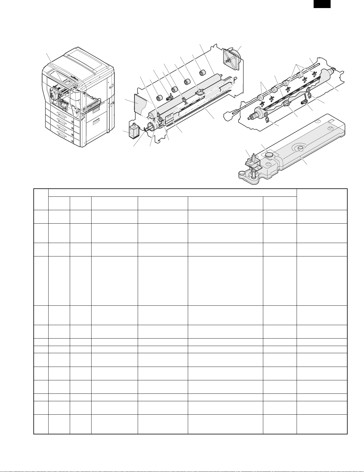
(6) Fusing, paper exit section
a. Fusing unit
1
AR-C150
6
26
5
4
26
3
2
26
26
7
25
15
16
15
14
8
13
24
20
9
10
12
11
Parts
No.
Code
1 Fusing unit Heats and presses toner on the
2 THS3 THS3 Fusing main
3 DPID DPID Duplex paper entry
4 THS1 THS1 Fusing sub
5 HLTSU HLTSU Thermostat (upper) Cuts conduction of the heater
6 Cleaning roller
7 FUSM FUSM Fusing drive motor Drives the fusing unit.
8 Oil felt Supplies oil to the oil roller.
9 Oil blade Controls the oil quantity on the oil
10 Oil roller Applies oil to the upper heat
11 Upper heat roller Heats and presses toner on the
12 HL1 HL1 Upper heater lamp Halogen lamp Heats the heat roller. 1000W
13 DGS DGS Duplex gate
14 Fusing control
Signal
name
Name Type Function/Operation
paper to fuse it onto the paper.
temperature sensor
(upper)
detector
temperature sensor
(upper)
(upper)
solenoid
PWB (AC sub PWB)
Thermistor Detects the heat roller surface
Photo sensor (Photo
transmission)
Thermistor Detects the heat roller surface
temperature.
Detects paper entry to the duplex
unit.
temperature.
lamp when the temperature rises
abnormally.
Cleans the fusing roller (upper)
surface.
roller to be even.
roller.
paper to fuse it onto the paper.
Drives (open/close) the duplex
paper entry gate.
Interfaces the heater lamp drive
control, sensor, and detector
signals.
23
21
Active
condition
Analog input
L when paper
entry
Analog input When a temperature
difference from the
fusing main
temperature sensor
(upper) is detected, it
is judged that paper
is wrapped around
the fusing roller.
17
19
18
22
Note
5 – 14
Page 46

AR-C150
Parts
No.
Code
15 Lower separation
16 HL2 HL2 Lower heater lamp Halogen lamp Heats the heat roller. 700W
17 Lower heat roller Heats toner on the paper to fuse
18 BPD BPD Fusing paper entry
19 THS2 THS2 Fusing main
20 THS4 THS4 Fusing sub
21 FOP FOP Oil pump Sends oil to the oil roller.
22 Oil tank Stores oil.
23 OEMP OEMP Oil sensor Photo sensor (Photo
24 HLTSD HLTSD Thermostat (lower) Cuts conduction to the heater
25 Fusing transport
26 Idle roller Applies a pressure to the paper
b. Paper exit unit
Signal
name
Name Type Function/Operation
Separate paper mechanically
pawl
detector
temperature sensor
(lower)
temperature sensor
(lower)
roller
Photo sensor (Photo
transmission)
Thermistor Detects the heat roller surface
Thermistor Detects the heat roller surface
refraction)
which was not separated from
the lower heat roller.
it onto the paper.
Detects paper entry in the fusing
section.
temperature.
temperature.
Detects oil empty. H when empty
lamp when the temperature rises
abnormally.
Transports paper to the paper
exit roller.
and the transport roller to give
the transport roller power to the
paper.
Active
condition
L when paper
entry in the
fusing section
Analog input
Analog input When a temperature
Note
difference from the
fusing main
temperature sensor
(lower) is detected, it
is judged that paper
is wrapped around
the fusing roller.
1
3
4
2
4
Parts
No.
Code
1 Paper exit unit Discharges the fused paper outside the
2 POD POD Paper exit detector Photo sensor (Photo
3 Paper exit roller Discharges paper outside the machine.
4 Idle roller Applies a pressure to the paper and the
Signal
name
Name Type Function/Operation
machine.
Detects paper exit. L with paper
transmission)
paper exit roller to give the paper exit
roller power to the paper.
Active
condition
presence
Note
5 – 15
Page 47

(7) Image process section
a. Toner hopper unit
5
1
6
7
6
7
Parts
No.
Code Signal name Name Type Function/Operation
1 Hopper unit Stores toner and transports toner to the
2 Toner transport
screw
3 Toner pipe shutter Prevents toner from spilling.
4 Shutter spring Spring for the shutter
5 Toner hopper
shutter
6 Toner stirring plate Stirs toner in the toner hopper.
7 TM
(Y, M, C, K)
TM
(Y, M, C, K)
Toner supply motor Synchronous
motor
b. Image process frame section
5
5
5
6
7
6
7
6
developing unit.
Transports toner to the developing unit.
Shutter for the toner supply port.
Transports toner to the developing unit,
and stirs toner.
10
AR-C150
2
3
4
Active
Note
condition
No.
Code Signal name Name Type Function/Operation
1 Image process
frame unit
2 PTHS PTHS Temperature
sensor
2
3
1
5
5
4
Parts
Mounts the developing unit and
the OPC drum unit on it.
Thermistor Detects temperature in the image
process section.
5 – 16
Active
Note
condition
Analot input Each correction of
image process
section is made by
this sensor data.
Page 48

AR-C150
No.
3 Process control
Code Signal name Name Type Function/Operation
Interface the developing unit, the
PWB
OPC drum unit, high voltage PWB,
and PCU PWB.
4 DSD holder F Keeps the distance between the
OPC drum and the developing
roller constant.
Parts
5 OPC drum fixing
Fixes the OPC drum shaft.
sleeve
c. Developing unit
7
1
2
3
4
9
5
8
Active
Note
condition
6
14
13
13
1213
11
10
Parts
No.
Code Signal name Name Type Function/Operation
1 Developing unit (Y) Changes yellow latent
electrostatic images to visible
toner images.
2 Developing unit (M) Changes magenta latent
electrostatic images to visible
toner images.
3 Developing unit (C) Changes cyan latent
electrostatic images to visible
toner images.
4 Developing unit (K) Changes black latent
electrostatic images to visible
toner images.
5 DV seal Shields and prevents toner
from leaking.
6 DV side seal F Shields and prevents toner
from leaking.
7 DV side seal R Shields and prevents toner
from leaking.
8 DMS
(Y, M, C, K)
DMS
(Y, M, C, K)
Drum mark sensor Photo sensor
(Photo reflection)
Detects the mark on the OPC
drum.
9 Doctor Controls toner quantity on the
developing roller to be even.
10 Developing roller
main pole position
Adjusts the developing roller
main pole position.
adjustment plate
Active
Note
condition
Analog input Controls the OC
drum phase and
identifies it.
5 – 17
Page 49

AR-C150
No.
11 TCS
Code Signal name Name Type Function/Operation
(Y, M, C, K)
TCS
(Y, M, C, K)
Toner concentration
sensor
Magnetic Detects the ratio of carrier and
toner in the developing unit.
12 Developing roller Adheres toner onto the OPC
drum.
13 Toner mixing roller Stirs toner and carrier to make
the toner concentration even
and charges the both.
14 Absorbing duct Removes toner dispersed
around the developing roller.
d. Main charger unit
Parts
Active
Note
condition
Analog input Installed to each
developing unit.
Prevents against
dirty copy by
dispersed toner.
Parts
No.
Code
Signal
name
Name Type Function/Operation
1 Main charger unit (Y) Charges yellow photoconductor negatively.
2 Main charger unit (M) Charges magenta photoconductor negatively.
3 Main charger unit (C) Charges cyan photoconductor negatively.
4 Main charger unit (K) Charges black photoconductor negatively.
5 Charger case Case for charging
6 Charger grid Controls the photoconductor charging potential.
7 Charger electrode Electrode for charging
e. OPC drum unit
5
1
2
3
4
5
6
6
7
Active
Note
condition
10
9
8
11
7
8
11
5 – 18
Page 50

AR-C150
Parts
No.
f. Transfer section
Code
1 OPC drum unit (Y) Forms yellow latent electrostatic images.
2 OPC drum unit (M) Forms magenta latent electrostatic images.
3 OPC drum unit (C) Forms cyan latent electrostatic images.
4 OPC drum unit (K) Forms black latent electrostatic images.
5 DL DL Discharge lamp Discharges electric charges on the OPC drum.
6 OPC drum Forms latent electrostatic images.
7 Cleaning blade Cleans residual toner from the OPC drum.
8 Waste toner
9 Shutter spring Spring for the shutter
10 Shutter Prevents toner from dispersing.
11 Toner seal Shields toner to prevent against leakage.
Signal
name
Name Type Function/Operation
Discharges waste toner from the OPC drum unit.
transport screw
Active
condition
Note
4
3
5
6
2
12
7
11
9
8
10
18
1
7
17
16
14
15
26
13
27
19
24
4
22
5
2
6 6 6
5 5 5
12
6
15
14
3
No.
Code
1 Transfer unit Transfers toner from the OPC
2 Transfer belt
Signal
name
8
separation pawl
10
Name Type Function/Operation
16
Parts
13
drum to paper.
Separates paper from the
transfer belt mechanically.
5 – 19
21
25
Active
condition
23
20
Note
Page 51

Parts
No.
Code
3 BPSS BPSS Separation pawl
4 Transfer belt drive
5 Transfer discharge
6 Transfer roller Applies a transfer voltage to
7 Lift cam Transmits the transfer belt lift
8 PCS PCS Image density sensor Photo sensor
9 BLUM BLUM Transfer belt motor Stepping motor Lifts the transfer belt unit.
10 CALS CALS Sensor switch
11 TC high voltage
12 Transfer belt Transfers toner images on
13 Waste toner tank Collects toner of toner patch
14 Transfer belt
15 Transfer belt idle
16 Transfer belt
17 BLUD BLUD Transfer belt position
18 BTM BTM Transfer belt drive
19 PSM PSM Resist roller drive
20 HUD HUD Temperature sensor Detects humidity in the
21 PCU sub PWB Controls the image process
22 Oil pump Supplies fusing oil to the
23 PPD1 PPD1 Paper detector in
24 Upper resist roller Transports paper to the
25 Lower resist roller Transports paper to the
Signal
name
Name Type Function/Operation
Drives the separation
solenoid
roller
electrode
solenoid
power PWB
cleaning blade
roller
cleaning pad
sensor
motor
motor
front of resist roller
(Photo reflection)
Photo sensor
(Photo
transmission)
Stepping motor Drives the transfer belt.
Stepping motor Drives the resist roller and
Photo sensor
(Photo
transmission)
solenoid.
Drives the transfer belt.
Discharges electric charges
of the transfer belt.
the transfer belt.
motor power to the transfer
unit.
Detects toner patch density in
image density correction.
Selects the image density
sensor.
Generates the high voltage
for transfer.
the OPC drum onto paper.
used in image density
correction.
Cleans toner of toner patch
used in image density
correction.
Applies a tension to the
transfer belt.
Cleans the back of the
transfer belt.
Detects that the transfer belt
is lifted up or down.
controls ON/OFF.
machine.
section.
fusing roller.
Detects paper in front of the
resist roller.
transfer section.
transfer section.
AR-C150
Active
condition
4 pcs (Y, M, C, K)
4 pcs (Y, M, C, K)
Lifted up in color
print mode, and lifted
down in
monochrome mode.
Analog input
Switches the sensor
angle depending on
detection of color
toner patch density
or black toner patch
density.
L when lifting
up H when
lifting down
Analog input Each correction of
image process
section is made
according to this
sensor data.
L with paper
presence
This detector signal
serves as the paper
transport timing
control signal to the
transfer section.
The operation timing
is controlled by the
resist roller motor.
Note
5 – 20
Page 52

AR-C150
No.
Code
26 BELTCH1 BELTCH1 Transfer belt
27 BELTCH2 BELTCH2 Transfer belt
g. Waste toner collection unit
Signal
name
installation detection
switch (+24V)
installation detection
switch (+5V)
Parts
Name Type Function/Operation
Micro switch Turns ON/OFF the +24V
power line from the DC main
power PWB to the PCU PWB.
Micro switch Turns ON/OFF the +5V
power line from the DC main
power PWB to the PCU PWB.
Active
condition
ON when the
transfer unit
operation is
allowed.
ON when the
transfer unit
operation is
allowed.
Note
2
1
Parts
No.
Code
1 Coupler Transmits the black developing drive
2 Coupler spring Applies a tension to the coupler.
3 Waste toner screw Transports waste toner to the waste toner
4 Waste toner bottle Collects waste toner.
5 TFD TFD Waste toner full sensor Photo sensor (Photo
Signal
name
Name Type Function/Operation
motor power to the waste toner transport
screw.
bottle.
Detects waste toner full. H when
transmission)
3
Active
condition
bottle empty
and waste
toner full
4
5
Note
5 – 21
Page 53

(8) Drive section
12
11
10
14
13
AR-C150
1
6
5
4
3
8
9
2
7
Parts
No.
Code
1 Developing drive unit (Color) Drives the color developing unit.
2 DVCM DVCM Developing drive motor
3 OPC drum drive unit (K) Drives black OPC drum unit.
4 OPC drum drive unit (C) Drives cyan OPC drum unit.
5 OPC drum drive unit (M) Drives magenta OPC drum unit.
6 OPC drum drive unit (Y) Drives yellow OPC drum unit.
7 DMK DMK OPC drum drive motor (K) Stepping motor Drives black OPC drum unit.
DMC DMC OPC drum drive motor (C) Stepping motor Drives cyan OPC drum unit.
DMM DMM OPC drum drive motor (M) Stepping motor Drives magenta OPC drum unit.
DMY DMY OPC drum drive motor (Y) Stepping motor Drives yellow OPC drum unit.
8 MPFC MPFC Manual paper feed clutch Electromagnetic
9 TRC TRC Paper transport clutch Electromagnetic
10 Paper transport drive unit Transmits the paper feed motor power to
11 PFM PFM Paper feed drive motor DC brushless
12 Paper feed drive motor Transmits the paper feed motor power to
13 DVKM DVKM Developing drive motor
14 Developing drive unit (Black) Drives the color developing unit.
Signal
name
(Color)
(Black)
Name Type Function/Operation
DC brushless
motor
clutch
clutch
motor
DC brushless
motor
Drives the color developing unit.
Transmits the paper feed motor power to
the manual paper feed unit. (Controls
ON/OFF.)
Transmits the paper feed motor power to
each transport roller. (Controls ON/OFF.)
each transport roller.
Drives the paper feed section and the
paper transport section.
the paper transport section and the
manual paper feed section.
Drives the black developing unit.
Active
condition
Note
5 – 22
Page 54

AR-C150
C. Functional parts
(1) Sensors and detectors
50
49
48
47
46
45
44
43
58
1 234
9
5
8
7
6
11
10
12 15
13
14
57
19
21
24
54
53
16
18
20
22
23
17
51
52
55
56
42
No.
Code
Signal
name
Name Type Function/Operation Active condition
1 MHPS MHPS Scanner home
position sensor
2 PD PD Document size
sensor
3 DMSY DMSY Drum mark
sensor (Y)
4 DVCHY DVCHY Developing unit
installation
detection (Y)
4041
39
37
35
33
32
34
36
38
Parts
Photo sensor (Photo
transmission)
Photo sensor (Photo
Detects the scanner home
position.
Detects the original size. Analog input
transmission)
Photo sensor (Photo
reflection)
Detects the mark on the OPC
drum.
Short harness Detects the developing unit
installation and identifies it.
25
26
27
28
29
30
31
Note
H in the home
position
Analog input Controls the OPC
drum phase and
identifies the OPC
drum.
Analog input
5 – 23
Page 55

Parts
No.
10 DMSC DMSC Drum mark
11 DVCHC DVCHC Developing unit
12 TCSC TCSC Toner density
13 DMSK DMSK Drum mark
14 DVCHK DVCHK Developing unit
15 TCSK TCSK Toner density
16 PPD1 PPD1 Paper feed
17 HUD HUD Humidity sensor Humidity sensor Detects humidity in the image
18 PFD1 PFD1 Paper detector 1 Photo sensor (Photo
19 RDSW-U RDSW-U Right upper door
20 LUD1 LUD1 Paper upper limit
21 PED1 PED1 Paper empty
22 PFD2 PFD2 Paper detector 2 Photo sensor (Photo
23 LUD2 LUD2 Paper upper limit
Code
5 TCSY TCSY Toner density
6 DMSM DMSM Drum mark
7 DVCHM DVCHM Developing unit
8 TCSM Toner density
9 OCSW OCSW Original cover
Signal
name
Name Type Function/Operation Active condition
Magnetic Detects the ratio of toner and
sensor (Y)
sensor (M)
installation
detection (M)
sensor (M)
open/close sensor
sensor (C)
installation
detection (C)
sensor (C)
sensor (K)
installation
detection (K)
sensor (K)
detector in front
of resist roller
open/close
detector
(actuator)
detector (No. 1
paper feed tray)
detector (No. 1
paper feed tray)
detector (No. 2
paper feed tray)
Photo sensor (Photo
reflection)
Short harness Detects the developing unit
Magnetic Detects the ratio of toner and
Photo sensor (Photo
transmission)
Photo sensor (Photo
reflection)
Short harness Detects the developing unit
Magnetic Detects the ratio of toner and
Photo sensor (Photo
reflection)
Short harness Detects the developing unit
Magnetic Detects the ratio of toner and
Photo sensor (Photo
transmission)
transmission)
Photo sensor (Photo
transmission)
Photo sensor (Photo
transmission)
Photo sensor (Photo
transmission)
transmission)
Photo sensor (Photo
transmission)
carrier in the developing unit.
Detects the mark on the OPC
drum.
installation and identifies it.
carrier in the developing unit.
Detects open/close of the
original cover. (Generates the
timing signal for detection of
the original size.)
Detects the mark on the OPC
drum.
installation and identifies it.
carrier in the developing unit.
Detects the mark on the OPC
drum.
installation and identifies it.
carrier in the developing unit.
Detects paper in front of the
resist roller.
process section.
Detects paper exit from No. 1
paper tray (duplex).
Detects open/close of the right
upper door.
Detects the upper limit of
paper. (Makes the friction
between the paper pickup
roller and paper constant.)
Detects paper empty on the
paper tray.
Detects paper exit from No. 2
paper tray (duplex).
Detects the upper limit of
paper. (Makes the friction
between the paper pickup
roller and paper constant.)
AR-C150
Note
Analog input
Analog input Controls the OPC
Analog input
Analog input
L when the
cover is open
Analog input Controls the OPC
Analog input
Analog input
Analog input Controls the OPC
Analog input
Analog input
L with paper
presence
Analog input Each correction of
L with paper
presence
H when the
door is open
L when the
paper upper
limit is detected
L (0V) when
detecting paper
presence.
L with paper
presence
L when the
upper limit is
detected
drum phase and
identifies the OPC
drum.
drum phase and
identifies the OPC
drum.
drum phase and
identifies the OPC
drum.
This detector signal
serves as the paper
transport timing
control signal to the
transfer section.
image process
section is made by
this sensor data.
5 – 24
Page 56

AR-C150
Parts
No.
24 PED2 PED2 Paper empty
25 PFD3 PFD3 Paper detector 3 Photo sensor (Photo
26 LUD3 LUD3 Paper upper limit
27 PED3 PED3 Paper empty
28 RDSW-L RDSW-L Right lower door
29 PFD4 PFD4 Paper detector 4 Photo sensor (Photo
30 LUD4 LUD4 Paper upper limit
31 PED4 PED4 Paper empty
32 C4PD1 C4PD1 Lift position
33 C4SS1 – 4 C4SS1 – 4 Paper size
34 C3PD1 C3PD1 Lift position
35 C3SS1 – 4 C3SS1 – 4 Paper size
36 C2PD1 C2PD1 Lift position
37 C2SS1 – 4 C2SS1 – 4 Paper size
38 C1PD1 C1PD1 Lift position
39 C1SS1 – 4 C1SS1 – 4 Paper size
40 PCS PCS Image density
41 BLUD BLUD Transfer belt
42 TFD TFD Waste toner full
43 BPD BPD Fusing section
44 THS2 THS2 Fusing main
45 OEMP OEMP Oil sensor Photo sensor (Photo
Code
Signal
name
Name Type Function/Operation Active condition
Photo sensor (Photo
detector (No. 2
paper feed tray)
detector (No. 3
paper feed tray)
detector (No. 3
paper feed tray)
open/close
detector
(actuator)
detector (No. 4
paper feed tray)
detector (No. 4
paper feed tray)
sensor 1 (No. 4
paper tray)
detector (Switch)
sensor 1 (No. 3
paper feed tray)
detector (Switch)
sensor 1 (No. 2
paper feed tray)
detector (Switch)
sensor 1 (No. 1
paper feed tray)
detector (Switch)
sensor
position sensor
detector
paper entry
detector
temperature
sensor (lower)
transmission)
transmission)
Photo sensor (Photo
transmission)
Photo sensor (Photo
transmission)
Photo sensor (Photo
transmission)
transmission)
Photo sensor (Photo
transmission)
Photo sensor (Photo
transmission)
Photo sensor (Photo
transmission)
Tact switch Detects the paper size set
Photo sensor (Photo
transmission)
Tact switch Detects the paper size set
Photo sensor (Photo
transmission)
Tact switch Detects the paper size set
Photo sensor (Photo
transmission)
Tact switch Detects the paper size set
Photo sensor (Photo
transmission)
Photo sensor (Photo
transmission)
Photo sensor (Photo
transmission)
Photo sensor (Photo
transmission)
Thermistor Detects the heat roller surface
refraction)
Detects paper empty on the
paper tray.
Detects paper exit from No. 3
paper tray (duplex).
Detects the upper limit of
paper. (Makes the friction
between the paper pickup
roller and paper constant.)
Detects paper empty on the
paper tray.
Detects open/close of the right
lower door.
Detects paper exit from No. 4
paper tray (duplex).
Detects the upper limit of
paper. (Makes the friction
between the paper pickup
roller and paper constant.)
Detects paper empty on the
paper tray.
Detects the lift plate position.
(Detects the paper quantity.)
with the paper size set block.
Detects the lift plate position.
(Detects the paper quantity.)
with the paper size set block.
Detects the lift plate position.
(Detects the paper quantity.)
with the paper size set block.
Detects the lift plate position.
(Detects the paper quantity.)
with the paper size set block.
Detects the toner patch
density in image density
correction.
Detects that the transfer belt
is lifted up or down.
Detects waste toner full. H when bottle
Detects paper entry in the
fusing section.
temperature.
Detects oil empty. H when empty
L (0V) when
detecting paper
presence.
L with paper
presence
L when the
upper limit is
detected
L (0V) when
detecting paper
presence.
H when the
door is open
L with paper
presence
L when the
upper limit is
detected
L (0V) when
detecting paper
presence.
H when
detecting.
H in the sensor
position
H in the sensor
position
H in the sensor
position
Analog input
L when lifting up
H when lifting
down
empty and
waste toner full
L when paper
entry in the
fusing section
Analog input
(in the air)
Note
5 – 25
Page 57

Parts
No.
46 THS4 THS4 Fusing sub
47 DPID DPID Duplex paper
48 POD POD Paper exit
49 THS1 THS1 Fusing main
50 THS3 THS3 Fusing sub
51 MTOP1 MTOP1 Tray position
52 MTOP2 MTOP2 Tray position
53 MPED MPED Paper detector Photo sensor (Photo
54 MPWS MPWS Paper size
55 MPLD1 MPLD1 Paper size
56 MPLD2 MPLD2 Paper size
57 OHPD OHPD OHP paper
58 PTHS PTHS Temperature
Code
Signal
name
Name Type Function/Operation Active condition
Thermistor Detects the heat roller surface
temperature
sensor (lower)
entry detector
detector
temperature
sensor (upper)
temperature
sensor (upper)
detector 1
detector 2
(width) sensor
(length) detector 1
(length) detector 2
sensor
sensor
Photo sensor (Photo
transmission)
Photo sensor (Photo
transmission)
Thermistor Detects the heat roller surface
Thermistor Detects the heat roller surface
Contact switch Detects the paper tray
Contact switch Detects the paper tray
transmission)
Variable resistor Detects the paper width. AR-C150
Photo sensor (Photo
transmission)
Photo sensor (Photo
transmission)
Photo sensor (Photo
reflection)
Thermistor Detects temperatre in the
Analog input When a difference
temperature.
Detects paper entry in the
duplex unit.
Detects paper exit. L with paper
temperature.
temperature.
position.
position.
Detects paper empty on the
paper tray.
Detects the paper length. AR-C150, L
Detects the paper length. AR-C150, L
Detects OHP paper AR-C150,
image process section.
L when paper
entry
presence
Analog input
Analog input When a difference
AR-C150, L
when collecting
AR-C150, H
when collecting
AR-C150, L
when paper
presence
when paper
presence
when paper
presence
Analog input
Analog input Each correction of
AR-C150
Note
from the fusing
main temperature
sensor (upper) is
detected, it is
judged that paper is
winding around the
fusing roller.
from the fusing
main temperature
sensor (upper) is
detected, it is
judged that paper is
winding around the
fusing roller.
image process
section is mode by
this sensor data.
5 – 26
Page 58

AR-C150
(2) Switches
12
3
No.
Code
1 MSW MSW Main power switch Rocker
2 DSWF DSWF Front door switch Micro
3 DHSW DHSW Dehumidifier
4 BELTCH1 BELTCH1 Transfer belt
5 BELTCH2 BELTCH2 Transfer belt
Signal
name
Name Type Function/Operation Active condition
switch
switch
Rocker
heater switch
installation
detection switch
(+24v)
installation
detection switch
(+24v)
switch
Micro
switch
Micro
switch
5
4
Parts
Turns ON/OFF the main power.
Turns ON/OFF the power line (+5V)
to the front door open/close detection
and the scanner (writing) unit.
Turns ON/OFF the power line to the
dehumidifier heater installed in the
scanner (reading) section and the
paper feed section.
Turns ON/OFF the +24V power line
from the DC main sub power PWB to
the PCU PWB.
Turns ON/OFF the +24V power line
from the DC main sub power PWB to
the PCU PWB.
5 – 27
Note
Turns ON when the
transfer unit is set in
the operating position.
Turns ON when the
transfer unit is set in
the operating position.
Page 59

(3) Clutch solenoids
AR-C150
1
2
3
4
Parts
No.
Code
1 MPFC MPFC Manual paper feed
Signal
name
clutch
Name Type Function/Operation
Magnetic
clutch
2 MPFS MPFS Manual paper feed
solenoid
3 TRC TRC Paper transport clutch Magnetic
clutch
4 CPFC1 CPFC1 Paper feed clutch (No.
1 paper feed tray)
Magnetic
clutch
5 CPFS1 CPFC1 Pickup solenoid (No. 1
paper feed tray)
6 CPFC2 CPFC2 Paper feed clutch (No.
2 paper feed tray)
Magnetic
clutch
7 CPFS2 CPFS2 Pickup solenoid (No. 2
paper feed tray)
8 CPFC3 CPFC3 Paper feed clutch (No.
3 paper feed tray)
Magnetic
clutch
9 CPFS3 CPFS3 Pickup solenoid (No. 3
paper feed tray)
1213 14
Transmits the paper feed motor
power to the manual paper
feed unit. (Controls ON/OFF.)
Controls ON/OFF of the paper
feed roller. Presses the paper
pickup roller onto paper.
Transmits the paper feed motor
power to the transport rollers.
(Controls ON/OFF.)
Turns ON/OFF the paper feed
roller.
Presses the paper pickup roller
onto paper.
Turns ON/OFF the paper feed
roller.
Presses the paper pickup roller
onto paper.
Turns ON/OFF the paper feed
roller.
Presses the paper pickup roller
onto paper.
Active
condition
5
6
7
8
9
10
11
Note
5 – 28
Page 60

AR-C150
Parts
No.
Code
10 CPFC4 CPFC4 Paper feed clutch (No.
11 CPFS4 CPFS4 Pickup solenoid (No. 4
Signal
name
Name Type Function/Operation
4 paper feed tray)
paper feed tray)
Magnetic
clutch
Turns ON/OFF the paper feed
roller.
Presses the paper pickup roller
onto paper.
12 CALS CALS Sensor switch solenoid Switches the image density
sensor.
13 BPSS BPSS Separation pawl
solenoid
Drives the transfer separation
pawl.
14 DGS DGS Duplex gate solenoid Drives the duplex paper entry
gate.
(4) Drive motors
1 2 3 4 5 6 7 8 9
Active
condition
Note
Switches the sensor
angle when color toner
patch density or black
toner patch density is
detected.
20
10
11
19
12
13
14
15
16
1718
Parts
No.
Code
Signal
name
Name Type Function/Operation
1 TMY Toner supply motor (Y) Synchronous motor Transports toner to the developing
unit. Stirs toner.
2 DMY DMY OPC drum drive motor (Y) Stepping motor Drives Yellow OPC drum unit.
5 – 29
Active
condition
Note
Page 61

Parts
No.
Code
3 TMM TMM Toner supply motor (M) Synchronous motor Transports toner to the developing
4 DMM DMM OPC drum drive motor (M) Stepping motor Drives magenta OPC drum unit.
5 TMC TMC Toner supply motor (C) Synchronous motor Transports toner to the developing
6 DMC DMC OPC drum drive motor (C) Stepping motor Drives cyan OPC drum unit.
7 TMK TMK Toner supply motor (K) Synchronous motor Transports toner to the developing
8 DMK DMK OPC drum drive motor (K) Stepping motor Drives black OPC drum unit.
9 SM SM Scanner motor Stepping motor Drives the scanner unit.
10 DVKM DVKM Developing drive motor
11 PFM PFM Paper feed drive motor DC brushless motor Drives the paper feed section and the
12 PSM PSM Resist roller drive motor Stepping motor Drives the resist roller and controls
13 LLM1 LLM1 Lift motor (No. 1 paper feed
14 LLM2 LLM2 Lift motor (No. 2 paper feed
15 LLM3 LLM3 Lift motor (No. 3 paper feed
16 LLM4 LLM4 Lift motor (No. 4 paper feed
17 BLUM BLUM Transfer belt drive motor Stepping motor Lifts the transfer belt unit.
18 BTM BTM Transfer belt drive motor Stepping motor Drives the transfer belt.
19 DVCM DVCM Developing drive unit (Color) DC brushless motor Drives the color developing units.
20 FUSM FUSM Fusing drive motor DC brushless motor Drives the fusing unit.
Signal
name
Name Type Function/Operation
unit. Stirs toner.
unit. Stirs toner.
unit. Stirs toner.
DC brushless motor Drives the black developing unit.
(Black)
paper transport section.
ON/OFF.
Synchronous motor Drives the lift plate.
tray)
Synchronous motor Drives the lift plate.
tray)
Synchronous motor Drives the lift plate.
tray)
Synchronous motor Drives the lift plate.
tray)
(5) Lamps
AR-C150
Active
condition
Note
1
2
3
4
No.
1 CL CL Scanner lamp Halogen lamp Radiates lights to the CCD
2 HL2 HL2 Lower heater lamp Halogen lamp Heats the heat roller. 1000W
3 HL1 HL1 Upper heater lamp Halogen lamp Heats the heat roller. 700W
4 DL (Y, M, C, K) DL (Y, M, C, K) Discharge lamp Discharges electric charges
Code Signal name Name Type Function/Operation Active condition
Parts
to read original images.
on the OPC drum.
Installed in each
OPC drum unit.
Note
5 – 30
Page 62

AR-C150
(6) Fans
1
2
3
4
Parts
No.
Code Signal name Name Type Function/Operation
1 CFM CFM Cooling fan (motor) Axial fan Cools the scanner (reading)
section.
2 LSUFM LSUFM LSU (Scanner (writing)
Axial fan Cools the scanner (writing) section. PWM control
unit) cooling fan (motor)
3 VFM VFM Fusing ventilation/
cooling fan (motor)
4 OZFM OZFM Ozone ventilation fan
(motor)
Axial fan Ventilates and cools the fusing
section.
Silocco fan Ventilate ozone and toner from the
image process section.
(7) Belts, drive wire
2
3
Active
condition
ON only in
copying
Note
PWM control
PWM control
Rotation only in
copying
1
6
7
2
3
4
5
5 – 31
Page 63

AR-C150
No.
Name Function/Operation
Parts
1 Scanner drive belt Transmits the scanner motor power to the scanner unit.
2 Developing drive belt (K) Transmits the black developing drive motor power to the developing unit.
3 Resist roller drive belt Transmits the resist roller drive motor power to the resist roller.
4 Waste toner screw drive belt Transmits the black developing drive motor power to the waste toner screw.
5 Paper feed drive belt Transmits the paper feed motor power to the paper feed section and the paper
transport section.
6 Scanner wire Transmits the scanner motor power to the scanner unit.
7 Developing drive belt (Y, M, C) Transmits the color developing drive motor power to the develoing unit.
(8) PWB
1
2
3
4
9
10
31
12
8
5
6
7
Note
22
14
15
25
26
No.
13
Name Function/Operation
11
27
18
23
24
Parts
20
19
16
17
28
29
30
20
1 Operation PWB L Outputs the key operation signals.
2 OP control PWB Controls the whole operation unit. (Displays information from the PCU PWB, and
sends operation information to the PCU PWB.)
3 Operation PWB R Outputs the key operation signals.
4 LCD back light inverter PWB Drives the LCD back light.
5 ICU-Main PWB Controls the ICU SCN PWB, ICU IMG PWB, and CCD PWB. Converts digital
image data into video signals and sends them to the scanner (writing) unit.
6 ICU-SCN PWB Performs correction of images outputted from the CCD.
7 ICU-IMG PWB Performs image processes such as area separation, color correction, black
generation, gamma correction, and filter process.
8 CPT PWB Recognizes the bank note patterns.
9 Original size sensor PWB
Detects the original size.
(Light reception)
28
Differs in AR-C150
and AR-C100.
Differs in AR-C150
and AR-C100.
Differs in AR-C150
and AR-C100.
1719
2930
Note
5 – 32
Page 64

AR-C150
No.
10 Original size sensor (Light
emitting)
11 CCD power PWB Outputs the CCD PWB paper power.
12 Scanner motor PWB Scanner motor control PWB. Controls the
13 PCU sub PWB Controls the image process section.
14 High voltage power PWB
(MC/DV)
15 Main charger interface PWB Interfaces the main charger power.
16 OPC drum motor control PWB Controls (drives) the OPC drum motor.
17 Scanner lamp control PWB Controls the scanner lamp
18 Humidity sensor PWB Detects humidity in the machine. Each correction of
19 PCU PWB (A) Controls the engine section. Differs in AR-C150
20 PCU PWB (B) Controls the engine section. Differs in AR-C150
21 Paper tray lift unit control PWB Controls the paper tray lift unit. Provided in each
22 Discharge lamp PWB unit Discharges electric charges on the OPC drum.
23 IFD PWB Equipped with No. 1/2 paper tray paper exit detectors and the right upper door
24 PFD PWB unit Equipped with No. 3/4 paper tray paper exit detectors and the right lower door
25 Process control PWB Interfaces signals between the developing unit, OPC drum unit, the high voltage
26 Fusing control PWB (AC sub
PWB)
27 High voltage power PWB (TC) Generates the transfer voltage.
28 DC main power PWB Generates the voltage used by the other units than the operation unit.
29 DC sub power PWB Generates the voltage used by the operation unit.
30 AC main power PWB Controls the primary side power (AC power).
31 CCD PWB Converts original images (light) into electrical signals.
Name Function/Operation
Outputs light to detect the original size.
Generates the high voltage for main charger and the developing bias voltage.
open/close detector.
open/close detector.
PWB, and the PCU PWB.
Interfaces the heater lamp drive control, sensor, detector signals.
Parts
Note
scanner motor.
image process
section is made by
this sensor data.
and AR-C100.
and AR-C100.
paper tray lift unit.
5 – 33
Page 65

(9) Fuses, thermostat
1
16
15
14
13
12
11
10
AR-C150
2
4
3
5
17
6
No.
1 F1 Scanner motor
2 HLTSU Upper heat roller
3 HLTSD Lower heat roller
4 F101 OPC drum motor
5 F701 Scanner lamp
6 F712 DC sub power
7 F711 DC sub power
8 F102 AC main power
Code Name Type Spec Function/Operation
power fuse
thermostat
thermostat
power fuse
power fuse
26V power fuse
primary size fuse
primary side fuse
AC main power
primary side fuse
AC main power
primary side fuse
7
8
Parts
Normal fuse Protects the scanner motor and its control
circuit from an overcurrent.
Thermostat Cuts conduction to the heater lamp when the
temperature rises abnormally.
Thermostat Cuts conduction to the heater lamp when the
temperature rises abnormally.
Normal fuse Protects the OPC drum motor and its control
circuit from an overcurrent.
Normal fuse 250V 4A Protects the scanner lamp from an overcurrent. Scanner lamp
Normal fuse 250V 1A Protects the PCC main PWB and the operation
control PWB form an overcurrent.
Normal fuse 250V 3.15A Protects the DC sub power primary side from
an overcurrent.
Normal fuse 125V 20A Protect the AC main power primary side from
an overcurrent.
Normal fuse 250V 15A Protect the AC main power primary side from
an overcurrent.
Normal fuse 240V 10A Protect the AC main power primary side from
an overcurrent.
9
Note
Scanner motor
control PWB
Fusing unit
Fusing unit
OPC drum motor
control PWB
control PWB
DC sub power
PWB
DC sub power
PWB
Japan
100V series
200V series
5 – 34
Page 66

AR-C150
No.
Code Name Type Spec Function/Operation
9 F101 AC main power
primary side fuse
AC main power
primary side fuse
AC main power
primary side fuse
10 F702 DC main power
+ 5V fuse
11 F703 DC main power
+ 5V fuse
12 F704 DC main power
+ 24V
DC main power
+ 24V
13 F705 DC main power
+ 24V
DC main power
+ 24V
14 F706 DC main power
+ 24V
DC main power
+ 24V
15 F707 DC main power
+ 24V
DC main power
+ 24V
16 F708 DC main power
+ 24V
DC main power
+ 24V
17 Scanner lamp
temperature fuse
(11) Power source
Parts
Normal fuse 125V 20A Protect the AC main power primary side from
Note
Japan
an overcurrent.
Normal fuse 250V 15A Protect the AC main power primary side from
100V series
an overcurrent.
Normal fuse 240V 10A Protect the AC main power primary side from
200V series
an overcurrent.
Normal fuse 125V 6.3A Protects the ICU PWB from an overcurrent. 100V series
Normal fuse 125V 6.3A Protects the PCU main PWB, LSU, and CCD
100V series
power PWB from an overcurrent.
Normal fuse 125V 6.3A Protects the PCU main PWB from an
100V series
overcurrent.
Normal fuse 250V 6.3A Protects the PCU main PWB and the high
200V series
voltage PWB (MC/DN) from an overcurrent.
Normal fuse 125V 6.3A Protects the PCU main PWB and the high
100V series
voltage PWB (MC/DN) from an overcurrent.
Normal fuse 250V 6.3A Protects the PCU main PWB from an
200V series
overcurrent.
Normal fuse 125V 6.3A Protects the scanner motor control PWB, LSU,
100V series
and CCD power PWB from an overcurrent.
Normal fuse 250V 6.3A Protects the scanner motor control PWB, LSU,
200V series
and CCD power PWB from an overcurrent.
Normal fuse 125V 6.3A Protects the process control PWB, the OPC
100V series
drum control PWB, and the developing motor
(color) from an overcurrent.
Normal fuse 250V 6.3A Protects the process control PWB, the OPC
200V series
drum control PWB, and the developing motor
(color) from an overcurrent.
Normal fuse 125V 6.3A Protects the PCU main PWB, RADF, the sorter,
100V series
the large capacity paper tray, the OPC drum
control PWB, and the developing motor (color)
from an overcurrent.
Normal fuse 250V 6.3A Protects the PCU main PWB, RADF, the sorter,
200V series
the large capacity paper tray, the OPC drum
control PWB, and the developing motor (color)
from an overcurrent.
Temperature
fuse
104°C 250V
10A
Cuts conduction to the scanner lamp when the
temperature rises abnormally.
1
3
2
7
4
5
6
5 – 35
Page 67

AR-C150
No.
1 CCD power PWB Outputs the CCD PWB power.
2 High voltage power
PWB (TC)
3 Fusing control PWB
(AC sub PWB)
4 DC main power PWB Generates a voltage used by the other unit than the operation unit.
5 DC sub power PWB Generates a voltage used by the operation unit.
6 AC main power PWB Controls the power (AC power) on the primary side.
7 High voltage power PB
(MC/DV)
Name Function/Operation Spec
Generates the transfer voltage.
Interfaces the heater lamp drive control, the sensor, and the
detector signals.
Generates the high voltage for the main charger and the developing
bias voltage.
Parts
(12) Adjustment volumes
2
Note
3
4
1
No.
1 VR1 HLV power voltage adjustment volume Adjusts the HLV voltage. DC sub power PWB
2 VR704 +3.4V power voltage adjustment volume Adjusts the +3.4V power voltage. DC main power PWB
3 VR703 +5V power voltage adjustment volume Adjusts the +5Vpower voltage. DC main power PWB
4 VR702 +24V power voltage adjustment volume Adjusts the +24V power voltage. DC main power PWB
Code Name Function/Operation
Parts
Note
5 – 36
Page 68

AR-C150
(13) Lock positions
1
2
4
3
No.
1 Scanner lock screw Locks the scanner. (Prevents the scanner from moving in transit.) Be sure to lock in transit.
2 Transfer unit lock screw Locks the transfer unit. (Prevents the transfer unit from moving in transit.)
3 Paper tray lock block Locks the paper lift plate.
4 Fusing, transfer unit lock screw Locks the fusing, transfer unit. (Prevents the transfer unit from projecting in
Name Function/Operation
transit.)
Parts
Note
5 – 37
Page 69

[6] MACHINE OPERATIONS
1. Operation mode
This machine has the following operation modes.
Mode Contents
Copy
mode
Printer mode Uses the print server (option) to
Power
save
mode
Simulation mode Used in servicing to set, adjust, and
Basic operation
mode
Special function
mode
Duplex copy
mode
Finishing mode Used to make various setups related
Job program
mode
User setup
mode
Operation
guidance mode
Pre-heat mode Used to lower the fusing temperature,
Sleep mode Used to stop the sections except for
Used to select paper and set the copy
magnification ratio and copy density,
etc.
Used to edit images and adjust color.
Used to make various setups of duplex
copy mode.
to the sorter.
Used to preset the copy operation
conditions.
Used to make setup of the
specifications according to the user’s
needs.
Help menu (Displays the operational
descriptions on copying.)
perform as a printer.
saving the power consumption.
the control PWB section.
check operations.
AR-C150
2. Operation menu
This machine has the following operation menus.
These operation menus differ depending on installation of options and
the configurations.
6 – 1
Page 70

Page 71

Page 72

AR-C150
Level 1 Level 2 Level 3 Level 4 Level 5
Job program
User setup
Program 1
Program 2
Program 3
Program 4
Program 5
Program 6
Program 7
Program 8
Program 9
Registration/Erase
Operation display brightness adjustment
Key operator program Dept. management Dept counter setup
Program selection
Program 1
Program 2
Program 3
Program 4
Program 5
Program 6
Program 7
Program 8
Program 9
Copy quantity total
Amount total
Total quantity/amount erase
Dept number setup
Copy unit price setup
Limitation of copy quantity
Warning for erroneous input of dept number
Function setup Key operator code change
Timer setup
User auto calibration
Inhibition setup Key touch alarm inhibition
Total copy quantity display
Program list print
Auto copy mode copy density adjustment
Toner save mode setup (Black/White)
Program magnification ratio setup
Copy quantity upper limit setup
Binding margin standard value setup
Edge erase width standard value setup
Copy mode standard state setup
Color balance Color balance test copy
Paper feed tray paper size setup
Operation inhibition mode setup
Stream feeding mode setup
Staple sorter bin paper exit quantity limitation cancel
Sleep mode setup
Auto clear time setup
Pre-heat mode setup
Message display time setup
Paper auto select inhibition
Tray auto select inhibition
Manual feed tray inhibition in duplex copy
Registered copy condition rewrite inhibition
Document feed unit use inhibition
Duplex copy inhibition
Staple inhibition
Cover mode inhibition
Copy inhibition in warning of size/direction
PC Modem access inhibition
Sleep mode inhibition
Black/white copy pre-scan inhibition
Color copy inhibition
Copy (Color)
Copy (Black/white)
Duplex
Document feed unit
Stapler
Self print (Color)
Self print (Black/white)
Printer (Color)
Printer (Black/white)
Displayed in Japan/ Outside UK
Displayed only when the RADF is installed
Displayed only when the sorter is installed
Use SIM 26-53 to set Enable/Disable
of this function.
Displayed only when the ADU is installed
Displayed only when the RADF is installed
Displayed only when the ADU is installed
Displayed only when the sorter is installed
Displayed only when the RADF is installed
Only in Japan
No display
Operation guidance
Toner supply (The menu display and "Operation Guidance"/"Toner supply" key are displayed only when toner concentration is decreased.)
Toner empty
Waste toner full (When the information key is pressed when in waste toner full, the waste toner collection paper replacement guidance is displayed.)
Duplex copy
Output
Document feed unit
Paper
Magnification ratio
Program
Interruption
Binding margin
1 set 2 copy
Centering
Cover insertion
OHP cover insertion
Color adjustment
Single color
Negative/Positive
Mirror image
Photo repeat
A3 wide copy
Enlargement continuous copy
Display contrast
(When the information key is pressed when in toner empty, the toner supply guidance is displayed.)
Displayed only when the ADU is installed.
Displayed only when the sorter is installed.
Displayed only when the RADF is installed.
Displayed only when the RADF is installed.
6 – 4
Page 73

AR-C150
3. Pre-heat mode and sleep mode
operations
A. Operation timing
This machine has a pre-heat mode and a sleep mode to save the
power consumption when copying (printing) is not performed.
The shift timing to the pre-heat mode and the sleep mode can be set
with the user program with the non-operating state as the start point.
The timing of the two modes can be separately set. It is possible to
shift from the normal mode directly to the sleep mode without passing
through the pre-heat mode.
Operation timing in the pre-heat mode and the sleep mode
Copy (print) operation
(Pre-heat mode cancel conditions)
In the following cases, the pre-heat mode is canceled.
(Sleep mode cancel condition)
In the following cases, the sleep mode is canceled.
Stop
Tp (Pre-heat
mode timer)
Tp and Ts are set by the user program.
Timer Set time
TP 10 - 240min
Ts
10 - 240min
Control section Phenomenon NOTE
Operation
section
Auditor section Card insertion (Only in the
Original size
sensor section
RADF section RADF original size change
Paper tray
section
Finishing Staple execution, (Front
Copy Copying
Self print Self printing
Printer control Printer operation
Scanner
(reading)
Copy Copying NOTE
Self print Self printing
Printer control Printer operation
Scanner
(reading)
Key input other than 10-key
(Including Key ON)
card counter mode) (Japan
only)
Coin insertion (Only in the
coin vendor mode) (Japan
only)
Original size change
(Including Original Empty
→ Presence, Presence →
Empty)
(Including Original Empty
→ Presence, Presence →
Empty)
Paper tray
attachment/detachment
detection, Paper tray lift
operation
take-up execution)
Scanner operation
Scanner operation
Pre-heat mode
Sleep mode
Ts (Sleep mode timer)
(Sleep mode shift timing extending condition)
When the non-operation of copying and printing continues and the following case occurs within 10 min of entering the sleep mode, set the
sleep mode timer to 10 min again, and extend the shift timing to the
sleep mode.
Control section Phenomenon NOTE
Operation
section
Auditor section Card insertion (Only in the
Original size
detection
(Original size
sensor section)
RADF section RADF original size change
Paper tray
section
Finishing (sorter) Staple execution, (Front
Copy Copying
Self print Self printing
Printer control Printer operation
Scanner
(reading)
Key input other than 10-key
(Including Key ON)
card counter mode) (Japan
only)
Coin insertion (Only in the
coin vendor mode) (Japan
only)
Original size change
(Including Original Empty
→ Presence, Presence →
Empty)
(Including Original Empty
→ Presence, Presence →
Empty)
Paper tray attachment/
detachment detection,
Paper tray lift operation
take-up execution)
Scanner operation
B. Pre-heat mode and sleep mode operations
(1) Control unit operations in the pre-heat mode and the
sleep mode
a. Operation (operation panel) section
Mode Operation NOTE
Sleep LCD display Does not display.
Pre-heat
mode
Normal
LED lights
up.
Key Printer/Copy key:
Original
detection
Card reader Does not operate. Japan only
Buzzer Operates. Controlled by
All load operations possible
Printer/Copy : Light
up.
Start, interruption,
data, online: Does
not light up.
Valid
Other keys: Invalid
Original size
sensor: Does not
operate.
Original cover
open/close
detection: Operates
PCU
6 – 5
Page 74

AR-C150
b.PCU PWB
Mode Operates. NOTE
Sleep Does not operate.
Preheat Refer to "d. Signals controlled by
the PCU PWB in the pre-heat
mode".
Normal Operates.
c.ICU PWB
Mode Operates. NOTE
Sleep Does not operate.
Low power
Normal Operates.
(Signals controlled by the PCU PWB in the pre-heat mode)
Section Signal name Content
Manual
paper feed
Paper feed
tray
Paper
transport
MPWS Manual feed width
detection
MPLD1 Manual feed
length detection
MPLD2 Manual feed
length detection
MTOP1 Manual feed tray
pull-out detection
MTOP2 Manual feed tray
pull-out detection
MPED Manual feed
paper empty
detection
C∗SS1 Paper size
detection
C∗SS2 Paper size
detection
C∗SS3 Paper size
detection
C∗SS4 Paper size
detection
PED∗ Paper empty
detection
LUD∗ Paper upper limit
detection
C∗PD1 Paper remaining
quantity detection
1
LUM_ENB∗ Paper tray lift-up
motor
PFD∗ Cassette paper
feed detection
PPD1 Paper detection in
front of RR roller
POD Machine paper
exit detection
PODF Finisher paper exit
detection
PFM Paper feed motor
TRC Transport clutch
MPFS Manual paper
feed solenoid
MPFC Manual paper
feed clutch
CPFS∗ Cassette paper
feed solenoid
CPFC∗ Cassette paper
feed clutch
RRM_START RR motor
Operation in the
pre-heat mode
Does not
operate.
Does not
operate.
Does not
operate.
Section Signal name Content
Developing PRD_AN? Toner
concentration
detection
Fusing HLPR HL power relay ON
Waste
toner
Image
process
Coin
vendor
(Japan
only)
Scanner
(reading)
Copy lamp CL Scanner lamp Does not
Fan CFM Scanner (reading)
Others DSWF Front door open
TBBOX Waste toner bottle
installation
detection
TFD Waste toner full
detection
DMENB All OPC drum
drive motor
DVKM Developing motor
(Black)
DVCM Developing motor
(Color)
HPCH Toner hopper
installation
detection
PRD_ANRTH Image process
temperature
detection
CV_COPY B/W copy allow
signal
CV_CLCOPY Color copy allow
CV_COUNT Count signal Does not
CV_START Copy start signal
CV_COLOR Color signal
CV_SIZE0 Size signal 0
CV_SIZE1 Size signal 1
CV_SIZE2 Size signal 2
CV_SIZE3 Size signal 3
MHPS Mirror home
SMENB Scanner (writing)
VFPWM Fusing
LSUPWM LSU cooling fan
OZFM Ozone exhaust
DDSW Paper exit door
RDSWU Paper fed upper
RDSWD Paper feed lower
PSPR Main power relay OFF
MCLKA Paper tray lift
MCLKB
DHPR Dehumidifier
signal
position detection
motor
cooling fan
exhaust/cooling
fan
(LSUFM)
fan
detection
open detection
door open
detection
door open
detection
motor/Toner motor
heater power relay
Operation in the
pre-heat mode
Does not
operate.
Does not
operate.
Does not
operate.
❍
(No Money
insertion →
Detection ;
pre-heat mode
canceled)
operate.
Does not
operate.
operate.
Does not
operate.
Operates. (Only
the fusing
exhaust fan is
operable.)
Does not
operate.
Does not
operate.
Does not
operate.
Operates.
6 – 6
Page 75

AR-C150
d. Communication in the pre-heat mode
Section Signal name Content
PCU SUB
PWB
ADU TXD_ADU ADU data send Does not
RADF TXD_RADF RADF data send Operates.
Sorter RES_SOT SOT reset Operates.
LCC TXD_LCC LCC data send Operates.
RIC I/F TXD_RIC RIC data send Does not
ICU PWB ICU_RXD ICU data receive Does not
Operation
unit
TXD_SUB PCU SUB data
send
RXD_SUB PCU SUB data
receive
BELTCH Transfer belt
pull-out detection
RXD_ADU ADU data receive
RES_ADU ADU reset
ADU_CH ADU pull-out
detection
RXD_RADF RADF data receive
RES_RADF RADF reset
RXD_LCC LCC data receive
RES_LCC LCC reset
RXD_RIC RIC data receive
DTR_RIC Machine power
ON signal
DSR_RIC RIC power ON
signal
ICU_TXD ICU data send
ICU_RES ICU reset signal
OPE_TXD Data send to OPE Operates.
OPE_RXD Data receive from
OPE
OPE_RES OPE reset signal
Operation in the
pre-heat mode
Operates.
operate.
operate.
operate.
(2) Fusing section operation in the pre-heat mode and
the sleep mode
Mode
Ready condition 177°C 132°C
Copy (Print
mode)
Pre-heat mode 137°C OFF
Sleep mode OFF OFF
Normal paper 170°C 125°C
OHP sheet 180°C 175°C
Thick paper 180°C 135°C
Control temperature
Upper heat roller Lower heat roller
4. Consumable parts life and machine operation
The relationship between the consumable parts life and the machine
operation is as shown in the table below.
Consumable parts Condition Operation Message
Toner K Low toner About 30-sheet
copy (print)
allowed
Y,M,C Low toner About 30-sheet
K Toner
empty
Y,M,C Toner
empty
Developer K,Y,M,C Life Copy (print)
OPC
drum
Waste
toner
bottle
Fusing oil Oil empty Copy (print) is
K,Y,M,C Life Copy (print)
OPC
drum
section
Transfer
section
Life Copying
Life Copying
copy (print)
allowed
Copying
(printing) is
stopped after
completion of
the half-way
copy (print).
All copy (print)
including color
copy inhibited.
Copying
(printing) is
stopped after
completion of
the half-way
copy (print).
(Monochrome
copy is allowed.)
allowed
allowed
(printing) is
stopped after
completion of
the half-way
copy (print).
(printing) is
stopped after
completion of
the half-way
copy (print).
immediately
stopped.
Copy
allowed/
Supply toner
Copy
allowed/
Supply toner
Toner empty
Toner empty
Maintenance
required
Maintenance
required
Replace
toner
collection
bottle
Transfer unit
toner
collection
bottle full
H6 trouble
(Fusing oil
empty)
6 – 7
Page 76

AR-C150
[7] SETTING AND ADJUSTMENTS
1. List of setup items
Set item
SET M1 Auto color balance adjustment target setup 46-21,
SET M2 Auto color balance adjustment target
selection
SET M3 User auto color calibration (Copy color
balance, auto density adjustment)
SET M1 Auto color balance adjustment target
setup
A. Outline
Auto color balance adjustment is performed with a certain color
balance (gamma) as a target. There are following two kinds of targets:
Only the service target among them allows optional setup of a color
balance (gamma) target.
1) Service target
This is provided to correct the shift in the reference color balance
(gamma) due to the machine fluctuations.
An optional color balance (gamma) target can be set according to
the user’s request.
In addition, the default target can be used as the service target.
Normally this is set to the standard color balance (gamma).
2) Factory target
This is the color balance (gamma) target which is set in the fac-
tory.
It is set to the standard color balance (gamma), and can be used
when the service target falls in an abnormal state by some
reasons.
It cannot be changed in the market.
When shipping from the factory, the service setup and the factory
setup are the same color balance (gamma) target.
This setup must be performed in the following cases:
• When the copy color balance and the density adjustment is
manually performed. (SIM 46-21)
• When a U2 trouble occurs.
• When the ICU main PWB is replaced.
• When the EEPROM on the ICU main PWB is replaced.
B. Setup procedure
(Procedure to set the standard color balance (gamma) or
an optional color balance (gamma) as the service target)
1) Two sheets of color patch image (adjustment pattern) are outputted in the copy color balance adjustment (manual adjustment)
(SIM 46-21). (ADJ M17/ADJ3)
At that time, when the color balance is shifted from the standard,
an adjustment is required. If not, there is no need to adjust.
If an optional color balance is required according to the user’s request, an adjustment is required.
Related
simulations
63-7, 63-8
63-8, 46-24
26-53
2) Enter the SIM 63-7 mode.
3) Press the SETUP key.
4) Set the color patch image (adjustment pattern) paper printed in
the copy color balance adjustment (manual adjustment) (SIM 46-
21) (ADJ M17/ADJ3) on the original table.
Set the paper on the original table so that the darker density side
comes on the left side. Then place 5 sheets of white paper on the
color patch image (adjustment pattern).
5) Press the EXECUTE key.
The color patch image (adjustment pattern) is read.
6) Press the REPEAT key and set the second color patch image (adjustment pattern) on the original table.
7) Press the OK key.
The color balance (gamma) corresponding to the color patch
image (adjustment pattern) printed in the copy color balance adjustment (manual adjustment) (ADJ M17/ADJ3) is set as the service target.
(Procedure to set the default (standard) color balance
(gamma) as the service target)
1) Enter the SIM 63-8 mode.
2) Press the EXECUTE key.
3) Press the YES key.
The service target becomes the same as the default (standard)
target.
NOTE: To reset to the original service target, SET M1 must be per-
formed.
7 – 1
Page 77

AR-C150
SET M2 Auto color balance adjustment target
selection
There are following two kinds of targets, and one of them can be
selected.)
(Selection procedure of the service or the factory target)
In the auto color balance adjustment (SIM 46-24), the selection menu
is shown to allow selection between SERVICE and FACTORY.
SET M3 User auto color calibration (Copy color
balance, auto density adjustment)
enable setup
A. Outline
The user can perform the copy color balance and auto density adjustment in the user program mode.
SIIM 26-53 is used to Enable or Disable this operation.
NOTE: This setup is performed only when the user understands the
copy color balance and the auto density adjustment and is
capable of performing the operation.
Full explanations on the operating procedure, notes, and
operations must be given to the user.
• When a U2 trouble occurs.
• When the PCU main PWB is replaced.
• When the EEPROM on the PCU main PWB is replaced.
B. Setup procedure
1) Enter the SIM 26-53 mode.
2) Select Enable/Disable with the 10-key.
Disabling = 0: YES
Enabling = 1: NO
3) Press the OK key.
When "0: YES" (Disabling) is selected, the user auto color calibration
(copy color balance, auto density adjustment) menu is not displayed
in the user program mode.
2. List of adjustment items
ADJUSTMENT ITEM SIMULATION
ADJ M1 DV doctor gap adjustment
ADJ M2 DV roller main pole position adjustment
ADJ M3 Toner concentration control reference level
ADJ M4 High voltage adjustment ADJ 1 Main charger grid voltage adjustment 8-2
ADJ M5 Paper skew adjustment 44-2
ADJ M6 Image density sensor adjustment ADJ 1 Image density sensor calibration 44-13
ADJ M7 Image skew adjustment (Scanner (Writing)
ADJ M8 Photoconductor phase adjustment 44-20
ADJ M9 Main scanning direction copy magnification
ADJ M10 Sub scanning direction color image resist
ADJ M11 Image distortion adjustment ADJ 1 Scanner (Reading) unit parallelism adjustment
ADJ M12 Image focus (Main scanning direction copy
ADJ M13 Sub scanning direction copy magnification
ADJ M14 Image position adjustment (Main scanning
ADJ M15 Image position adjustment (Main scanning
setting
unit)
ratio adjustment (Scanner (Writing) unit)
Main scanning direction image registration
adjustment (Scanner (Writing) unit)
adjustment (Scanner (Writing) unit) (Color)
magnification ratio) adjustment (CCD position
adjustment)
ratio adjustment
direction) (Print engine)
direction) (Scanner (Writing)
ADJ 2 DV bias voltage adjustment 8-1
ADJ 3 Transfer voltage adjustment 8-3
ADJ 2 Image density sensor sensing position adjustment 44-23
ADJ 1 Main scanning direction copy magnification ratio adjustment
(Scanner (Writing) unit) (Black)
ADJ 2 Main scanning direction color image resist adjustment
(Scanner (Writing) unit) (Color)
Main scanning direction copy magnification ratio adjustment
(Scanner (Writing) unit) (Color)
ADJ 2 Image distortion adjustment (Sub scanning direction)
ADJ 3 Image distortion adjustment (Main scanning direction)
25-2/44-27
64-1
61-4
50-10
50-20
50-21
48-1
50-10
50-12
7 – 2
Page 78

AR-C150
ADJUSTMENT ITEM SIMULATION
ADJ M16 "Image position, image loss, void area
adjustment"
ADJ M17 Image quality adjustment ADJ 1 CCD gamma adjustment 63-3 (63-5)
ADJ 2 Image color balance adjustment (Auto) 46-24
ADJ 3 Image color balance adjustment (Manual) 46-21
ADJ 4 Copy color balance adjustment (for each copy mode) 46-10 ∼ 19, 1, 2
ADJ M18 Document size sensor adjustment ADJ 1 Original size sensor detection point adjustment 41-2
ADJ 2 Original size sensor sensitivity adjustment 41-2
ADJ M19 Waste toner full detection level adjustment
ADJ M20 Touch panel coordinates setting 65-1
ADJ M21 Transfer belt level adjustment
(Transfer belt traveling adjustment)
ADJ M22 Fusing pressure adjustment
ADJ M23 Power voltage adjustment ADJ 1 3.4 V power voltage adjustment
ADJ 2 5.0 V power voltage adjustment
ADJ 3 24 V power voltage adjustment
ADJ M24 Manual feed paper size sensor adjustment 40-2
ADJ M25 OHP sensor adjustment 40-5
50-1/50-2
ADJ M1 DV doctor gap adjustment
This adjustment must be performed in the following cases:
• When the developing unit is disassembled.
• When the print density is low.
• When there is a lot of toner dispersion abnormally.
1) Remove the developing unit from the copier, and remove the
developing unit cover and the blade cover.
2) Loosen the DV doctor fixing screw A.
3) Insert a 0.525 thickness gauge at the point of 40mm ∼ 70mm from
the DV doctor edge.
40mm
30mm
30mm
40mm
4) Push the DV doctor in the arrow direction and tighten the DV doctor fixing screw.
(Perform the same procedure for the front and the rear frame
simultaneously.)
5) Check that the clearance is 0.525 ±0.03mm at two positions which
are 40mm ∼ 70mm from the both sides of the DV doctor.
∗ When inserting the thickness gauge, be careful not to scratch the
DV doctor and the MG roller.
ADJ M2 DV roller main pole position
adjustment
This adjustment must be performed in the following cases:
• When the developing unit is disassembled.
• When the print density is low.
• When there is a lot of toner dispersion abnormally.
1) Remove the developing unit cover and the blade cover, and place
the developing unit on a flat surface.
2) Tie a string to a needle or a pin.
3) Hold t h e str i ng and put the need le ho r iz on t al ly and move it toward
the MG roller. (Do not use a clip which is too big to have a correct
position.)
4) With the needle tip at 2 ∼ 3mm from the MG roller surface, mark
the point on the surface which is on the extended line of the
needle tip. (Do not make contact between the needle tip and the
MG roller.)
5) Measure the distance between the marking position and surface P
of the developing unit, and check that the black unit is 13mm,
color unit 24mm.
If the distance is not as specified above, loosen the fixing screw A
of the main pole adjustment plate, and move the adjustment plate
in the arrow direction to adjust.
7 – 3
Page 79

2 ~ 3mm
2 ~ 3mm
AR-C150
4) When the [EXECUTE] key is pressed, it is highlighted. The OPC
drum drive motor rotates and the toner concentration sensor
detects toner concentration and the output value is displayed.
After stirring for 3 min, the average value of toner concentration sensor detection level is set (stored) as the reference toner concentration
control value.
NOTE: When the operation is stopped in 3 min, the adjustment
result is not registered.
When the [EXECUTE] key is pressed during rotation of the
motor, it is stopped and the [EXECUTE] key returns to the
normal display.
If "EE-EU" or "EE-EL" is displayed, it means that the reference toner concentration control value is not set normally.
EE-EL: Less than 79 (1.59V)
EE-EU: More than 177 (3.41V)
5) Execute SIM 24-5 to clear the developer counter.
6) Execute SIM 44-27 to reset the half tone correction data (correction conditions) to the default.
P
A
NOTE: 1) When replacing the color developer, replace the yellow,
Magenta, and Cyan developers at the same time.
If only one developer is replaced, the color balance may
be abnormal.
The black developer can be replaced alone.
2) After replacement of developers and the photoconductor,
be sure to execute SIM 44-27 to reset the half tone
correction data (correction conditions) to the default level.
If the above procedure is ignored, half tone correction
may not be performed properly.
13.0mm
black
2 ~ 3mm
A
24.0mm
color
ADJ M3 Toner concentration control reference
level setting
This adjustment must be performed in the following case:
• When the developer is replaced.
1) With the front cabinet open, enter the SIM 25-2 mode.
ADJ M4 High voltage adjustment
(Note) For adjustment of the output voltage, use internal impedance
of 1000Mohm or more and whose effective value can be
measured (Recommend: FLUKE87FLUKE80K-40). Use a
high voltage probe.
ADJ 1 Main charger grid voltage adjustment
This adjustment must be performed in the following cases:
• When the high voltage power (MC/DV) PWB is replaced.
• When a U2 trouble occurs.
• When the PCU main PWB is replaced.
• When the EEPROM of the PCU main PWB is replaced.
1) Enter SIM 8-2 mode.
2) Select the color mode to be adjusted with the scroll key and press
the [EXECUTE] key.
3) Check the output voltage with the high voltage probe, and adjust
the value of each color so that the specification in the table below
is satisfied.
Color Normal mode adjustment spec Check pin
K –525 ± 5V (5)
C –525 ± 5V (6)
M –525 ± 5V (7)
Y –525 ± 5V (8)
Enter the adjustment value with the 10-key and press the [OK] key.
2) Close the front cabinet.
3) Select the developing unit to be adjusted.
7 – 4
Page 80

AR-C150
(8)
(7)
(6)
(5)
GND
∗ With all the OPC drums removed from the machine, bring the high
voltage probe into contact with the high voltage PWB GB pin to
check the adjustment value.
ADJ 2 DV bias voltage adjustment
This adjustment must be performed in the following cases:
• When the high voltage power (MC/DV) PWB is replaced.
• When a U2 trouble occurs.
• When the PCU main PWB is replaced.
• When the EEPROM of the PCU main PWB is replaced.
1) Enter the SIM 8-1 mode.
2) Select the color mode to be adjusted with the scroll key and press
the [EXECUTE] key.
3) Check the output voltage with the high voltage probe, and adjust
the value of each color so that the specification in the table below
is satisfied.
Enter the adjustment value with the 10-key and press the [OK]
key.
Color Normal mode adjustment spec Check pin
K –325 ± 5V (1)
C –325 ± 5V (2)
M –325 ± 5V (3)
Y –325 ± 5V (4)
∗ Set the developing unit (K, C, M, Y), bring the high voltage probe
into contact with the high voltage PWB GS pin to check the
adjustment value.
ADJ 3 Transfer voltage adjustment
This adjustment must be performed in the following cases:
• When the high voltage power (TC) PWB is replaced.
• When a U2 trouble occurs.
• When the PCU main PWB is replaced.
• When the EEPROM of the PCU main PWB is replaced.
1) Enter the SIM 8-6 mode and enter the following values for each
color and press the OK key.
Transfer voltage input values
Display BK C M Y Note
Normal paper mode A: SPX 178 164 123 123
ADU mode B: DPX 178 164 123 123 AR-C150
OHP mode C: OHP 204 209 167 162
Thick paper mode D: HEAVY PAPER 204 187 138 138
Note: Do not press the EXECUTE key.
only
ADJ M5 Paper skew adjustment
This adjustment must be performed in the following cases:
• When the resist roller section is disassembled.
1) Enter the SIM 64-1 mode.
Select the black print mode.
2) Set the items as shown below:
A: 5
B: 255
C: 1
D: 9
E: Select A3 (11 × 17) paper size.
3) Press the [EXECUTE] key.
The grid pattern is printed. Check that the print line in the paper
transport direction is in parallel with both edges.
Paper edge Check that lines
La
are in parallel.
Lb
(1)
GND
(2)
(3)
(4)
Paper
Paper transport direction
If the above condition is not satisfied, perform the following procedure.
7 – 5
Page 81

AR-C150
4) Loosen the resist roller fixing screw, and change the resist roller
angle.
The standard position is at the center.
Repeat procedures 3) – 4) until the condition of procedure 3) is satisfied.
ADJ M6 Image density sensor adjustment
ADJ 1 Image density sensor calibration
This adjustment must be performed in the following cases:
• When the image density sensor is replaced.
• When the transfer belt is replaced.
• When a U2 trouble occurs.
• When the PCU main PWB is replaced.
• When the EEPROM of the PCU main PWB is replaced.
The process control sensor gain adjustment means: The detection
level differs between machines due to variations in density detection
sensors and parts. To prevent against this, attach a seal of a certain
density on the belt to calibrate the sensor.
1) With the power OFF, open the right cover of the machine.
2) Pull out the transfer unit, and attach the adjustment sheet (UKOG0281FCZZ) to the belt.
(The attachment position is between the two separation pawls of
the fusing unit.)
7) Check that the SIM 44-13 values are within the specifications.
Check content Spec
PCLEDC (Sensor current in color calibration) 128 or below
DARK ID (Color image density sensor dark
voltage)
P_PSI (Read value of calibration sheet) 102 ±5
P_CYI (Read value of calibration plate) 80 ±15
50 or below
∗ When an error message is displayed, clean the sensor and the
calibration plate, and adjust again.
∗ If the above procedure cannot cancel the error, replace the
sensor and the calibration plate.
8) Turn off the power.
9) Pull out the transfer unit, and remove the adjustment sheet.
(The adjustment sheet is positioned in front of the cleaning blade
at the back of the unit as the transfer belt rotates.)
10) Return the transfer unit.
NOTE: If the motor drive power is turned on immediately after at-
taching the adjustment sheet to the transfer belt, the adjustment sheet does not stop at the specified position and the
transfer belt keeps rotating.
As a result, the adjustment sheet may be damaged by the
transfer cleaning blade or the transfer cleaning blade may be
damaged by the adjustment sheet.
To prevent against this, be sure to observe the following.
1) Before entering the SIM 44-13 mode, open the right cover of
the machine to open the motor drive power line.
2) After completion of the adjustment, remove the adjustment
sheet from the transfer belt.
3) Return the transfer unit. With the front cover open, turn on the
power.
4) Enter the SIM 44-13 mode.
5) Close the front cover.
6) Press the [EXECUTE] key.
The adjustment is automatically performed. When the adjustment
is completed, the [EXECUTE] key returns to the normal display.
ADJ 2 Image density sensor sensing position
adjustment
This adjustment must be performed in the following cases:
• When the image density sensor is replaced.
• When the image density sensor section is replaced.
• When a U2 trouble occurs.
• When the PCU main PWB is replaced.
• When the EEPROM of the PCU main PWB is replaced.
1) Enter the SIM 44-23 mode.
2) Press the [EXECUTE] key. The adjustment is automatically performed, and the average data is displayed.
When the operation is completed, the [EXECUTE] key is highlighted.
In case of an abnormal end, "ERROR" is displayed.
7 – 6
Page 82

AR-C150
ADJ M7 Image skew adjustment (Scanner
(Writing) unit)
This adjustment must be performed in the following cases:
• When the scanner (writing) unit is replaced.
• When the scanner (writing) unit is removed from the machine.
• When a color image mis-resist occurs.
• When the installing location is changed.
1) Enter the SIM 64-1 mode.
Select the color mode of Black.
2) Set the values of A ∼ D of the set item as shown in the table
below, and make an A3 (11" × 17") copy. (The grid pattern is
printed.)
∗ Use the paper tray at the bottom.
SIM 64-1 set items
Parameter Set value
A PRINT PATTERN 5
B PRINT START GRADATION LEVEL 1
C SELF PRINT Q’TY SETTING 1
D DENSITY MODE 9
Enter the input value with the 10-key and press the OK key. When
the [EXECUTE] key is pressed, printing is performed. Paper is
selected by the set item E.
3) Check the distortion of the printed image.
If the right-angle level of the traverse print line is 0.5mm or less for
the longitudinal print line of paper, there is no need to adjust.
4) If the image is distorted, loosen the red screw for the holder on the
chassis side, and adjust the LSU inclination with the black LSU
adjustment screw (set screw). (The LSU at the right end is black.)
After completion of the adjustment, fix the holder with the red
screw.
Red screw for the holde
5) Enter the SIM 61-4 mode.
0.5mm or less
Comporison line
Right-angle
Reference line
Longitudinal direction
6) Select 11×17 paper and press the [EXECUTE] key. Paper is
selected by the set item B.
The check pattern is printed.
∗ Use the paper tray at the bottom.
7) Check that the center shift between the Y/M/C print color patters is
within 0 ± 1 step.
(Check the shift between the print patterns of the same color.
Even though there is some shift between different colors, there is
no problem.)
If the above condition is not satisfied, loosen the red screw for the
holder on the front side of the chassis, and adjust the LSU adjustment screw (set screw) to adjust the LSU inclination.
After completion of the adjustment, fix the holder with the red
screw.
Procedures 1) – 4): Black LSU adjustment procedures
Procedures 5) – 7): Color LSU adjustment procedures
7 – 7
Page 83

Compare the positions (front-rear) of the same color
AR-C150
Compare the positions (front-rear) of the same color print patterns.
Procedures 1) – 4) : Adjustment procedures of the black LSU
Procedures 5) – 7) : Adjustment procedures of the color LSU
ADJ M8 Photoconductor phase adjustment
This adjustment must be performed in the following cases:
• When the OPC drum is replaced.
• When the OPC drum is removed from the machine.
• When the OPC drum drive section is disassembled.
• When the OPC drum drive unit is replaced.
• When a U2 trouble occurs.
• When the PCU main PWB is replaced.
• When the EEPROM of the PCU main PWB is replaced.
1) Enter the SIM 44-20 mode.
2) Enter "2" in the setup item A (PRINT MODE) with the 10-key, then
press the [OK] key. (Default setting is 3.)
3) Select the paper feed cassette with A3 (11" × 17") paper in the
setup item E (PAPER SELECT), and press the [OK] key.
∗ Use the paper tray at the bottom.
4) Press the [EXECUTE] key, and the drum deflection adjustment
pattern is printed in four pages.
∗ Pattern N (1, 4, 7, 10) is printed.
7 – 8
Page 84

AR-C150
5) Check the deflection cycle of 125.6mm pitch of four printed patterns (C, M, Y). Use the output pattern of the smallest deflection
as the set value of each color, and set it to item B, C, and D. (After
entering the adjustment value, press the OK key.)
6) After entering the adjustment value, enter "3" to set item A with
the 10-key and press the [EXECUTE] key to print the adjustment
pattern again.
If the above procedures cannot bring a satisfactory result, select
mode 1 and print twelve pages of the print pattern.
This allows to make more detailed checks and adjustments.
The adjustment procedure is the same as procedure 5).
It, however, takes about 6 min to do this procedure.
NOTE: If there is an extra deflection other than the drum frequency
(125.6mm pitch), check the set values of the PS motor, the
belt motor, and the fusing motor speed.
125mm 125mm 125mm
Check the feflection of 125mm pitch.
7 – 9
Page 85

ADJ M9 Main scanning direction copy
magnification ratio adjustment
(Scanner (Writing) unit)
Main scanning direction image
registration adjustment (Scanner
(Writing) unit)
ADJ 1 Main scanning direction copy
magnification ratio adjustment (Scanner
(Writing) unit) (Black)
This adjustment must be performed in the following cases:
• When the black scanner (writing) unit is replaced.
• When a U2 trouble occurs.
• When the ICU main PWB is replaced.
• When the EEPROM of the ICU main PWB is replaced.
1) Enter the SIM 50-10 mode.
2) Select H: BLACK LD MAG.
3) Press the [EXECUTE] key.
4) Check that the dimension inside the printed half tone pattern is
221mm.
AR-C150
2) Select the paper feed cassette of A3 (11" × 17") paper in the setup
item H (PAPER SEL).
∗ Use the paper tray at the bottom.
3) Press the [EXECUTE] key. The adjustment pattern is printed.
4) Check the print patterns of the rough adjustment and the fine adjustment for equate color on the front and the rear side.
Rough adjustment print pattern check: Check that the rough adjustment print pattern is at the center for the rough adjustment reference pattern.
Fine adjustment print pattern check: Check that the fine adjustment print pattern is at the center for the fine adjustment reference
pattern.
(If the fine adjustment print pattern is in the range of 0 ± 1 for the
scale of the fine adjustment reference pattern, there is no need to
adjust.)
221mm
5) If the dimension is not as specified above, change the set value
and perform an adjustment again.
Enter the adjustment value with the 10-key and press the [OK]
key.
ADJ 2 Main scanning direction color image
registration adjustment (Scanner
(Writing) unit) (Color)
Main scanning direction copy
magnification ratio adjustment (Scanner
(Writing) unit) (Color)
This adjustment must be performed in the following cases:
• When the scanner (writing) unit is replaced.
• When the scanner (writing) unit is removed from the machine.
• When the main scanning direction image magnification ratio (scan-
ner (writing) unit (Black)) is performed.
• When a color image mis-resist occurs in the main scanning direc-
tion.
• When the installing position is changed.
• When a U2 trouble occurs.
• When the ICU main PWB is replaced.
• When the EEPROM of the ICU main PWB is replaced.
1) Enter the SIM 50-20 mode.
7 – 10
∗
A: Rough adjustment pattern
∗
B: Fine adjustment pattern
∗
C: Adjustment range (0±1)
Page 86

AR-C150
[How to read the pattern]
When deflection is made to the positive (+) side in the rough adjustment, increase the value on the positive (+) side.
When the deflection is made to the negative (–) side in the rough adjustment, increase the value on the negative (–) side.
When the read value is 27
(= 20 +7 ):
∗
C
B
(Example)
When the simulation is set to 105,
newly set to 132 (= 105 + 27).
20
When the read value is –27
(= –20 – 7):
∗
C
∗
A
∗
B
(Example)
When the simulation is set to 105,
newly set to 78 (= 105 – 27).
20
∗
A
∗A: Rough adjustment pattern
∗B: Fine adjustment pattern
∗C: Adjustment range
[Main scan registration adjustment pattern]
If the rough adjustment pattern or the fine adjustment pattern is not in
the above range, perform the following procedures.
5) Calculate the shift from the adjustment reference position for each
adjustment mode.
The sum of the shift of rough adjustment reference and the shift of
fine adjustment is the actual shift.
Shift (Correction value) = Rough adjustment shift + Fine adjustment shift
The interval between scales of the rough adjustment reference
corresponds to 20. Be careful of polarities of the shift (positive or
negative) when calculating.
6) Select the mode to be adjusted with the scroll key.
7) Add or reduce to or from the current adjustment value, enter the
obtained value, and press the [OK] key.
• When the shift (correction value) is positive:
Adjustment value = Current adjustment value + Shift (Correction value)
• When the shift (correction value is negative:
Adjustment value = Current adjustment value – Shift (Correction value)
8) Press the [EXECUTE] key.
The adjustment pattern is printed.
Check that the conditions of procedure 4) are satisfied.
Repeat procedures 4) – 8) until the conditions of procedure 4) are
satisfied.
(Note) When either of the adjustment values of the front and the
rear adjustment mode is changed, the other adjustment
print pattern may be varied. Be careful of that.
When the adjustment can be completed with a fine adjustment, perform the front adjustment mode first, and then
perform the rear adjustment mode after completion of the
front adjustment.
NOTE: Before performing this adjustment, be sure to adjust the K
magnification ratio (SIM 50-10, H) properly.
(Example) Set the simulation values as shown below.
A: 100
A: 93 (=100 –7)
B: 112 B: 100 (=112 –12)
C: 95 C: 96 (=95+1)
D: 98 D: 109 (=98+11)
→
Reset value
E: 102 E: 109 (=102+7)
F: 96 F: 118 (=96+22)
ADJ M10 Sub scanning direction color image
resist adjustment (Scanner (Writing)
unit) (Color)
This adjustment must be performed in the following cases:
• When the scanner (writing) unit is replaced.
• When the scanner (writing) unit is removed from the machine.
• When a color image mis-resist occurs in the sub scanning direc-
tion.
• When the installing position is changed.
• When a U2 trouble occurs.
• When the ICU main PWB is replaced.
• When the EEPROM of the ICU main PWB is replaced.
7 – 11
Page 87

AR-C150
1) Enter the SIM 50-21 mode.
2) Select the paper feed cassette of A4R (8 1/2" × 11") paper in the
setup item E (PAPER SEL).
∗ Use the paper tray at the bottom.
3) Press the [EXECUTE] key. The adjustment pattern is printed.
4) Check the rough adjustment print pattern position and the fine adjustment print pattern position for each color.
• Rough adjustment print pattern check
Check that the rough adjustment print pattern is at the center of
the rough adjustment reference pattern.
• Fine adjustment print pattern check
Check that the fine adjustment print pattern is at the center of
the fine adjustment reference pattern.
(If the fine adjustment print pattern is in the range of 0 ± 1 for the
scale of the fine adjustment reference pattern, there is no need to
adjust.)
∗
A
∗
A: Rough adjustment pattern
∗
B: Fine adjustment pattern
∗
C: Adjustment range
∗
C
∗
B
7 – 12
Page 88

AR-C150
[Sub scan registration adjustment pattern]
(Example) Set the simulation set values as shown below.
A: 100
B: 112 B: 129 (=112 + 17)
C: 95 C: 110 (=95+15)
→
Set value
A: 73 (=100 –27)
7 – 13
Page 89

[How to read the pattern]
When deflection is made to the positive (+) side in the rough adjustment, increase the value on the positive (+) side.
When the deflection is made to the negative (–) side in the rough adjustment, increase the value on the negative (–) side.
AR-C150
20
When the read value is –27
(= –20–7)
∗
A
∗
∗
C
B
When the read value is 27
(= 20+7)
–20
∗
C
(Example)
When the simulation is set to 105,
newly set to 132 (= 105 + 27).
∗
A: Rough adjustment pattern
∗
B: Fine adjustment pattern
∗
C: Adjustment range
If the rough adjustment pattern or the fine adjustment pattern is not in
the above range, perform the following procedures
5) Calculate the shift from the adjustment reference position for each
adjustment mode.
The sum of the shift of rough adjustment reference and the shift of
fine adjustment is the actual shift.
Shift (Correction value) = Rough adjustment shift + Fine adjustment shift
The interval between scales of the rough adjustment reference
corresponds to 20. Be careful of polarities of the shift (positive or
negative) when calculating.
6) Select the mode to be adjusted with the scroll key.
7) Add or reduce to or from the current adjustment value, enter the
obtained value, and press the [OK] key.
(Example)
When the simulation is set to 105,
newly set to 132 (= 105 – 27).
• When the shift (correction value) is positive:
Adjustment value = Current adjustment value + Shift (Correction value)
• When the shift (correction value is negative:
Adjustment value = Current adjustment value – Shift (Correction value)
8) Press the [EXECUTE] key.
The adjustment pattern is printed.
Check that the conditions of procedure 4) are satisfied.
Repeat procedures 4) – 8) until the conditions of procedure 4) are
satisfied.
NOTE: Before performing this adjustment, SIM 44-20 (drum phase
adjustment) must have been adjusted properly.
7 – 14
Page 90

AR-C150
ADJ M11 Image distortion adjustment
This adjustment must be performed in the following cases:
• When the scanner (reading) section is disassembled.
• When a cop image distortion occurs.
ADJ 1 Scanner (Reading) unit parallelism
adjustment
1) Loosen the screw which is fixing the scanner unit A and the drive
wire, and remove the scanner unit A from the drive wire.
Scanner unit A
7) With the scanner unit B in contact with two stoppers on the front
and the rear frame side simultaneously, slide the scanner unit A
until it comes to the right end of the frame, and fix it to the drive
wire with the fixing screw.
2) Manually turn the scanner drive gear to bring the scanner unit B
into contact with the stopper.
At that time, if the scanner unit B makes contact with the two stoppers on the front and the rear frame simultaneously, the parallelism of the scanner unit B is proper.
If not, perform the following procedures.
3) Loosen the fixing screw of the scanner unit drive pulley on the
side where the scanner unit B is not in contact with the stopper.
Scanner unit B
4) While keeping the scanner unit drive shaft stationary, turn the
scanner unit drive pulley manually so that the scanner unit B
makes contacts with two stoppers on the front and the rear frame
side simultaneously. (Change the relative positions of the scanner
unit drive pulley and the drive shaft.)
5) Fix the scanner unit drive pulley fixing screw which was loosened
in procedure 3).
6) Perform procedure 2).
Repeat procedures 3) – 6) until the parallelism of the scanner unit
B becomes proper.
7 – 15
Page 91

AR-C150
ADJ 2 Image sub scanning direction distortion
adjustment
1) Make a test chart on A3 (11 × 17") paper as shown below. (Draw
a rectangular with four right angles.)
2) Set the test chart made in procedure 1) on the document table.
(Leave a space of about 30mm between the reference position
and the test chart. With the document cover open, make a copy
on A3 (11 × 17").
5) With the scanner unit drive shaft kept stationary, turn the scanner
unit drive pulley manually to change the parallelism of scanner
units A and B. (Change the relative positions of the scanner unit
drive pulley and the drive shaft.)
6) Tighten the scanner unit drive pulley fixing screw.
Repeat procedures 2) – 6) until the condition of procedure 3) is
satisfied.
ADJ 3 Image scanning direction distortion
adjustment
1) Make a test chart on A3 (11 × 17") paper as shown below. (Draw
a rectangle with four right angles.)
2) Set the test chart made in procedure 1) on the document table.
With the document cover open, make a copy on A3 (11 × 17").
3) Check for distortion in the main scanning direction.
If the four angles of the rectangle on the copy are right angles,
there is no distortion. (Completion of the adjustment)
3) Check for distortion in the sub scanning direction.
If La = Lb, there is no distortion.
If there is some distortion in the sub scanning direction, perform
the following procedures.
4) Loosen either of two fixing screws of the scanner unit drive pulley.
(Either one on the front or the rear side will do.)
If there is some distortion in the main scanning direction, perform
the following procedures
4) Check for a difference between the right distortion and the left distortion (balance).
Lc
Copy A
Left distortion is equal
to right distortion.
Lc = Ld
Ld
Lc
Copy B
Ld
Left distortion is not equal
to right distortion
Lc ≠ Ld
If Lc = Ld, there is no difference between the left distortion and the
right distortion.
If the above condition is satisfied, go to procedure 6).
If the above condition is not satisfied, perform the following procedures.
7 – 16
Page 92

AR-C150
5) Change the height balance of the front frame side scanner rail.
Perform procedures 2) – 5) until there is no difference between
the left distortion and the right distortion.
6) When there is no difference between the left distortion and the
right distortion, change the height of the scanner rail on the front
frame side.
7) Set the test chart made in procedure 1) on the document table,
and make a copy on A3 (11 × 17") paper. Check that the main
scanning distortion is within the specified range.
Repeat procedures 6) – 7) until the main scanning direction distortion is within the specified range.
(Example) Fit 10mm of the scale with 10mm of the copied scale and
100mm scale
(Original)
Copy image
(1mm (1%)
shorter than the
original)
7) Remove the original guide L and R, and remove the table glass.
8) Remove the dark box cover.
9) Remove the slide pin of the front cover unit.
compare them.
Main scanning direction copy magnification ration
100 – 99
=
100
× 100 = 1
10 20 90 100 110
1.0mm
10 20 90 100 110
ADJ M12 Image focus (main scanning direction
copy magnification ratio) adjustment
(CCD position adjustment)
This adjustment must be performed in the following cases:
• When the CCD unit is removed from the machine.
• When the CCD unit is replaced.
• When the copy image focus is improper.
• When the copy magnification ratio in the main scanning direction is
improper.
(CCD unit installing position adjustment)
This adjustment is performed in the following case:
• when the CCD unit is replaced.
1) Enter the SIM 48-1 mode.
2) Set the set item B to 50 (initial value).
3) As shown in the figure below, place a scale on the original table.
10 20 3040 5060 70 8090 50 100110120130140
10) Loosen the CCD unit fixing screws.
4) Make a normal copy on A4 paper.
5) Compare the scale image length and the actual scale length.
6) Obtain the main scanning direction copy magnification ratio according to the following formula.
Main scanning direction copy magnification ratio
(Original length – Copy length)
=
Original length
× 100[%]
∗ Never loosen the screws which are not indicated in the figure
above. If loosened, the CCD unit must be replaced.
7 – 17
Page 93

11) Insert the slide pin as shown below, and make positioning in the
sub scanning direction. (Initial positioning is completed.)
A
B
(Example 1)
Copy A shorter
than the original
10
20
AR-C150
90 100 110
12) Make a copy in the initial position and check the copy
magnification ratio again.
If the copy magnification ratio is not in the range of 100 ± 1%, perform
the following procedure.
Repeat procedures 12) and 13) until the copy magnification ratio is
within the range of 100 ± 1%.
When the copy image is longer than the original, move in the
direction of B.
When the copy image is shorter than the original, move in the
direction of A.
One scale of scribe line corresponds to 0.2%.
13) Change the installing position in the CCD sub scanning direction
to adjust the magnification ratio.
NOTE: Due to the structure of the optical system, when the CCD unit
fixing position is changed with SIM 48-1 set to 50, the copy
magnification ratio is adjusted to the specified level (100 ±
1.0%) and the specified resolution is provided.
ADJ M13 Sub scanning direction copy
magnification ratio adjustment
This adjustment must be performed in the following cases:
• When the copy magnification ratio in the copy image sub scanning
direction is improper.
• When the scanner motor is replaced.
• When the scanner motor control PWB is replaced.
• When a U" trouble occurs.
• When the PCU main PWB is replaced.
• When the EEPROM of the PCU main PWB is replaced.
Before this adjustment, perform the focus adjustment (CCD unit installing position adjustment).
1) Place a scale on the original table as shown below.
102030 40
50 60 70
80 90 50
100
110
120130140
2) Enter the SIM 48-1 mode.
3) Make a normal copy and obtain the copy magnification ratios.
Copy magnification ratio
(Original dimension – Copy dimension)
=
Origi nal dimension
× 100[%]
Scale
(Original)
(Example 2)
Copy B longer
than the original
4) Check that the copy magnification ratio is within the specified
range (100 ± 1%).
If the copy magnification ratio is within the specified range (100 ±
1%), the adjustment is completed.
If not, perform the following procedure.
5) Change the scan mode adjustment value of SIM 48-1.
When the adjustment value is increased, the sub scanning direction copy magnification ratio is increased.
A change in the adjustment value by 1 corresponds to a change in
the copy magnification ratio by about 0.1%.
Repeat procedures 3) – 5) until the coy magnification ratio is
within the specified range (100 ± 0.28%).
NOTE: Fix the adjustment value of SIM 48-1 adjustment mode (F –
R) to 50.
10
20 90 100
10
20 90 100
110
110
ADJ M14 Image position adjustment (Main
scanning direction) (Print engine)
This adjustment must be performed in the following cases:
• When the paper tray is replaced.
• When the paper tray section is disassembled.
• When the manual paper feed tray is replaced.
• When the manual paper feed tray is disassembled.
• When the duplex section is disassembled.
• When the duplex section is installed or replaced.
• When the large capacity paper feed tray is installed or replaced.
• When the large capacity paper feed tray is disassembled.
• When a U2 trouble occurs.
• When the PCU main PWB is replaced.
• When the EEPROM of the PCU main PWB is replaced.
1) Enter the SIM 50-10 mode.
2) Select the paper feed mode to be adjusted with the scroll key.
3) Press the [EXECUTE] key.
The adjustment pattern is printed.
4) Check the adjustment pattern image position.
Measure the dimensions from the paper center to the front and the
rear edge of the adjustment pattern to check that they are the
same.
If A – B = ±2.0mm, there is no need to adjust.
If the above condition is not satisfied, perform the following proce-
dure.
7 – 18
Page 94

AR-C150
Half tone
A
A–B =±2.0mm
B
Half tone
5) Change the adjustment value.
(Enter the adjustment value and press the [OK] key.)
When the adjustment value is increased, the image is shifted
backward.
When the adjustment value is decreased, the image is shifted forward.
A change in the set value by 1 corresponds to a change in the
shift by about 0.1mm.
Repeat procedures 3) – 5) until the condition of procedure 4) is satisfied.
If the above condition cannot be satisfied with the above procedures,
perform the following procedures.
6) Loosen the paper feed tray cover fixing screw, and shift the installing position in the arrow direction.
Perform procedures from 2) again.
Direction A
Direction B
Perform the above procedures for all paper feed units.
ADJ M15 Image position adjustment (Main
scanning direction) (Scanner (Writing))
This adjustment must be performed in the following cases:
• When the scanner (reading) section is disassembled.
• When the scanner (reading) unit is replaced.
• When the RADF section is disassembled.
• When the RADF unit is installed.
• When the RADF unit is replaced.
• When a U2 trouble occurs.
• When the ICU main PWB is replaced.
• When the EEPROM of the ICU main PWB is replaced.
1) Set the adjustment chart on the document table.
2) Enter the SIM 50-12 mode.
The copy magnification ratio is automatically set to 400%.
3) Select the OC mode with the scroll key.
4) Press the COPY key. A copy is made.
5) Check the copy image center position.
If A – B = ± 4.0mm, there is no need to adjust. (400%)
If the above condition is not satisfied, perform the following procedures.
A
A – B = 4.0mm
(400%)
B
6) Change the adjustment value.
(Enter the adjustment value and press the OK key.)
When the adjustment value is increased, the image is shifted
backward. When the adjustment value is decreased, the image is
shifted forward.
A change in the set value by 1 corresponds to a change in the
shift by about 0.4mm. (400%)
Repeat procedures 4) – 6) until the condition of procedure 5) is satisfied.
ADJ M16 "Image position, image loss, void area
adjustment"
This adjustment must be performed in the following cases:
• When the scanner (reading) section is disassembled.
• When the scanner (reading) unit is replaced.
• When the resist roller section is disassembled.
• When a U2 trouble occurs.
• When the PCU main PWB is replaced.
• When the EEPROM of the PCU main PWB is replaced.
Before performing this adjustment, check that SIM 50-5 is set to 50.
If not, set it to 50.
This adjustment uses SIM 50-2 and SIM 50-1.
The above tow simulations are used in the following manner.
SIM 50-2: Rough adjustment
SIM 50-1: Fine adjustment
If the desired value is obtained by SIM 50-2, there is no need to per-
form SIM 50-1.
(Adjustment item) ∗1: Spec is 5.0mm or less
No. Adjustment item
1 Lead edge image loss IMAGE
2 Lead edge void area DEN-A DEN-A 1.5 to
3 Rear edge void area DEN-B DEN-B 1.5 to
4 Image reference position RRC-A
5 Paper timing RRC-B
6 Distance between image lead edge
position and scale of 10mm × 10
7 Distance between paper lead edge
and image lead edge × 10
Adjustment items 1 ∼ 3 can be adjusted either with SIM 50-1 or with
SIM 50-2.
The adjustment values 6 and 7 will affect the adjustment items 4 and
5 automatically.
Therefore, adjusting the items 6 and 7 will lead to the same result as
adjusting the items 4 and 5 directly.
1) Place a scale on the original table as shown below.
Note that the scale must be placed in parallel with the scanning
direction and that the scale lead edge must be in close contact
with the original guide plate.
SIM 50-2
set item
LOSS
L1
L2
SIM 50-1
set item
IMAGE
LOSS
Adjustment
value
1.5 to
3.0mm ∗ 1
3.0mm ∗ 1
3.0mm ∗ 1
7 – 19
Page 95

10 20 30 40 50 60 70 80 90 50 100110120130140
AR-C150
13) If the lead edge void area is not within the specified range,
change the DEN-A value.
14) If the lead edge void area is not within the specified range,
change the IMAGE LOSS value.
15) If the rear edge void area is not within the specified range,
change the DEN-B value.
Image loss
2) Enter SIM 50-2.
3) Set IMAGE LOSS and DEN-A to "20".
4) Set all the set items of L1 and L2 to "0".
5) Make a copy at 400%. (Original table mode)
6) Measure the copied image dimensions X and Y.
X: Distance between the copy image lead edge and the scale of
10mm
Y: Distance between the paper lead edge and the copy image
lead edge.
X
Paper lead
edge
10 20 30 40
Y
400% enlarged copy
50
Lead edge void area Lead edge void area
∗1: Spec is 5.0mm or less
Adjustment
item
IMAGE
LOSS
Lead edge
image loss
DEN-A Lead edge
void area
DEN-B Rear edge
void area
Adjustment
value
1.5 to
3.0mm ∗ 1
1.5 to
3.0mm ∗ 1
1.5 to
3.0mm ∗ 1
The greater the set value is,
the greater the image loss is.
The greater the set value is,
the greater the void area is.
The greater the set value is,
the greater the void area is.
Note
7) Mulliply X, Y, and Z by 10 to obtain L1, L2, and L3 respectively.
Enter the values of L1, L2, and L3.
L1 = X × 10
L2 = Y × 10
8) Cancel the simulation, make a copy, and check that the lead
edge image loss and void area are within the specified range
shown below.
Lead edge image loss: 1.5 ∼ 3.0mm
Lead edge void area: 1.5 ∼ 3.0mm
If the above specifications are not satisfied, perform the following procedures.
9) Enter SIM 50-1.
10) Set a scale in the same manner as procedure 3), and make a
copy at 50% and at 400% in the original table mode.
11) Measure the distance between the paper lead edge and the
copy image lead edge of 50% copy and of 400% copy.
12) Check that there is no difference between the above distance of
50% copy and that of 400% copy.
If there is a difference of 1.5mm or above, change the
adjustment value of RRC-A.
Repeat procedures 10) to 12) until the above specification is satisfied.
7 – 20
Page 96

AR-C150
ADJ M17 Image quality adjustment
Copy color balance density check
STAR T
(Check in the TEXT/Photo mode.)
(Test chart UKOG-0162FCZZ/
UKOG-0283FCZZ is used.)
Is the
copy color balance/
density adjustment
required ?
NO
YES
Was CCD replaced ?
NO
YES
Perform ADJ1 CCD gamma
adjustment.
Set the SIT chart
(UKOG-0280FCZZ) on
the original table.
Enter the SIM 63-03
mode and press the
EXECUTE key.
In the fine
adjustment, the copy
color balance and the density
are in the standard
level.
YES
Perform the manual adjustment of
ADJ3 copy color balance, density
adjustment. (SIM 46-21)
SET M1 Auto color balance adjustment target is set.
(SIM 63-7)
Enter the SIM 63-7 mode.
Press the SETUP key.
Set the color patch image (adjustment
pattern) printed in the copy color balance/
density adjustment on the original table, and
press the EXECUTE key.
Press the REPEAT key.
Press the EXECUTE key.
Press the OK key.
Cancel SIM 63-7.
Perform the initial setup of half tone image
correction. (SIM 44-21)
NO
NO
balance and the density
in the specified level ?
Are the color
YES
Perform ADJ2 copy color balance/density auto
adjustment. (SIM 46-24)
Enter the SIM 46-24 mode and select
C:A3 (11 17) paper. (Auto selection)
Press the EXECUTE key. (The
adjustment pattern 1 is printed.)
Set the adjustment pattern 1 on the
original table, select the SERVICE
mode, and press the EXECUTE key.
(Auto adjustment step 1)
Press the REPEAT key.
Press the EXECUTE key.
(Adjustment pattern 2 is printed.)
Set the adjustment pattern 2 on the
original table, and press
the EXECUTE key.
(Auto adjustment step 2)
Press the OK key. (The initial setup
of half tone image correction is
automatically performed.)
Cancel SIM 46-24.
END
Execute the half tone image correction.
(Forcible execution) (SIM 44-26)
Check the copy color balance and the
density. (Check in the Text/Photo mode.)
(Use the test chart UKOG-0283FCZZ.)
7 – 21
NO
Are the copy color balance and
the density in the specified level ?
Is the copy density
adjustment in the low density section
performed for all the copy modes ?
(Does the user request
NO
Is the color balance/
density adjustment
performed for each copy mode ? (Does
the user request that ?)
NO
for it ?)
YES
YES
YES
Perform the copy density
adjustment in the low
density section for ADJ4
each the copy modes.
(SIM 46-1/2)
Perform the copy density
adjustment in the low
density section for ADJ4
all the copy modes.
(SIM 46-10 – 19)
Page 97

AR-C150
Copy color balance and density check
Check the color balance and the density by making copies of Sharp
gray chart and the serviceman chart.
a. Note for the copy color balance check
To check the copy color balance and the density, use Sharp gray
chart and the serviceman chart and set the copy density in the
Text/Photo mode to Manual 3 and make a copy in the color mode and
in the black and-white mode. At that time, the color balance adjustment of the user program must be set to the default (center).
Be sure to use the specified paper for color.
[Sharp gray chart]
The copy image density of Sharp gray chart must be as follows:
(Color copy)
NOTE: Use the color test chart (UKOG-0283FCZZ) to check the
color balance.
Patch 1 is slightly copied.
12345678910 W
Patch 2 is clearly copied.
(Black-and-white copy)
Patch 3 is slightly copied.
12345678910 W
Patch 4 is copied.
Patches 1 and 2 are not copied.
[Serviceman chart (UKOG-0283FCZZ)]
Check the color balance of Serviceman chart copy is as shown below.
(Color copy)
Serviceman chart (Color patch section)
Patch 7 and the following must be copied.
Density balance of each color must be proper.
SHARP gray chart
SHARP GRAY CHART
SHARP gray chart
SHARP GRAY CHART
The background may
be slightly copied.
No great difference with
the original (Whole copy
of the patch section)
ADJ 1 CCD gamma adjustment
This adjustment must be performed in the following cases:
• When the CCD unit is replaced.
• When a U2 trouble occurs.
• When the PCU main PWB is replaced.
• When the EEPROM of the PCU main PWB is replaced.
When the CCD unit is replaced, be sure to perform this adjustment.
(1) Precautions for adjustment
1) Check that the table glass and No. 1, 2, 3 mirrors and lenses are
free from dust and dirt. (If there is dust and dirt, clean with alcohol.)
2) Check that there is no dirt or scratch on BK1 and BK2 patches of
SIT chart (UKOG-0280FCZZ).
If there is dirt, clean with alcohol.
If there is scratch, replace the chart with new one.
(2) Adjustment procedures
1) Set the SIT chart (UKOG-0280FCZZ) to the left edge of the
original table, and fit the center of SIT chart with the center of the
glass holder.
When SIT chart is not available, execute SIM 63-5 to set the CCD
gamma to the default. This method, however, provides a lower adjustment accuracy than the method by using SIT chart.
NOTE: Check that the SIT chart (UKOG-0280FCZZ) is closely
placed on the original table.
2) With the SIT chart fixed, close the original cover.
3) Enter the SIM 63-03 mode, and press the [EXECUTE] key.
The automatic adjustment is started. During the automatic adjustment, the [EXECUTE] key is highlighted. When the adjustment is
completed, the key returns to the normal display.
NOTE: The SIT chart (UKOG-0280FCZZ) is affected by light (espe-
cially by ultraviolet rays) and temperature and humidity. Put it
in a bag (clear file, etc.) and store in a dark place.
The life of the SIT chart is one year. Check the manufacturing date specified on the chart and replace every one year.
If the SIT chart is not available, execute SIM 63-5 instead of the
above procedure. This sets the CCD gamma to the default. The accuracy of this method is lower than the method using the SIT chart.
ADJ2 Auto color balance adjustment
This adjustment must be performed in the following cases:
• When a consumable part (developer, OPC drum, the transfer belt)
is replaced.
• When the CCD unit is replaced.
• When the scanner (reading) section is cleaned.
• When a U2 trouble occurs.
• When the ICU main PWB is replaced.
• When the EEPROM of the ICU main PWB is replaced.
a. Outline
The color balance adjustment (auto adjustment) is the automatic adjustment of cyan, magenta, yellow, and black copy density with SIM
46-24 or the user program.
There are following two modes of auto color balance adjustment.
1) Auto color balance adjustment by the serviceman (with SIM 46-
24)
2) Auto color balance adjustment by the user (with the user program)
(The color balance target becomes the service target.)
The auto color balance adjustment by the user is provided in order to
reduce the number of service calls.
If the coy color balance is shifted by some reason, the user performs
the color balance adjustment to correct it.
If, however, there is a basic problem in the machine, or if the machine
environment is changed largely, this function does not serve as an effective means.
7 – 22
Page 98

AR-C150
While the automatic color balance adjustment by the serviceman allows adjustment even when the machine environment is changed largely, providing normal color balance. If there is a basic problem in the
machine, repair it and adjust to provide normal color balance.
The above points must be fully understood for proper operation.
When this adjustment is performed, the color balance adjustment of
all the copy modes are changed.
(However, the color balance adjustment level of the user program is
not changed.)
b. Note for performing the color balance adjustment
(Auto adjustment)
1) The print engine section must be properly adjusted. (ADJ M2 –
M16)
2) CCD gamma adjustment must be properly adjusted. (ADJ M1)
3) When setting the color patch image (adjustment pattern) paper on
the original table, place 5 sheets of white paper on the color patch
image paper.
4) Be sure to use the specified color paper.
c. Adjustment procedure
(Auto color balance adjustment by the serviceman)
1) Enter the SIM 46-24 mode.
7) Set the color patch image (adjustment pattern) printed in procedure 6) on the original table so that the darker density side comes
to the left side. Place 5 sheets of white paper on the color patch
image (adjustment pattern) paper.
8) Press the EXECUTE key.
The copy color balance adjustment (step 2) is automatically performed, and the color balance check patch image is printed.
Wait for a while until the operation menu of procedure 9) is displayed.
2) Select A3 or 11 x 17 paper (auto select) and press the EXECUTE
key.
The color patch image (adjustment pattern) is printed.
3) Set the color patch image (adjustment pattern) printed in procedure 2) on the original table so that the dark density side of the
color p atch imag e com es to th e left sid e. Pl ace 5 shee ts of w hite
paper on the color patch image (adjustment pattern) paper.
4) Press the SERVICE key on the operation panel and press the EXECUTE key.
The copy color balance adjustment (step 1) is automatically performed, and the color balance check patch image is printed. Wait
for a wh ile until the operation menu of procedure 5) is dis played.
5) Press the REPEAT key on the operation panel.
9) Press the OK key on the operation panel.
The initial setup of half tone image correction is performed according to this adjustment data.
10) Check that the color balance check patch image printed at last is
within the specified range shown below.
Fig. 1 PG image
High density Low density
C
M
Y
Bk
Max
1) The max. density
section is not blurred.
4) Patch for each of C, M, Y, BK
The patch density is identical between patches or not
reversed.
The patch density is changed gradually.
3) B - E patches of each color of
Y, C, M, and Bk are copied very
slightly.
ABCDEFGHIJKLMNO
6) Press the EXECUTE key.
The color patch image (adjustment pattern) is printed.
11) Execute the half tone image correction. (Forcible execution)
(SIM 44-26)
12) Use the test chart UKOG-0283FCZZ and check the copy color
balance and the density in Text/Photo mode. (Refer to the
section of the copy color balance and the density.)
If the copy color balance and the density are not in the specified
level, perform the following procedures.
13) Perform initial setup of half tone image correction. (SIM 44-21)
14) Perform half tone image correction. (Forcible execution) (SIM
44-26)
7 – 23
Page 99

AR-C150
15) Use the test chart UKOG-0283FCZZ and check the copy color
balance and the density in Text/Photo mode. (Refer to the
section of the copy color balance and the density.)
Repeat procedures 13) – 15) until the spe cified l evel is obtained.
However, repetition is limited to three times.
If repetition of the above procedures does not set the copy color
balance and the density to the specified level, there may be some
other reason.
Investigate the reason and repair or fix the problem, then perform all
the procedures of print quality adjustment from the beginning.
If the above conditions are not satisfied, perform the manual adjustment (SIM 46-21 (ADJ M17/ADJ3).
(Auto color calibration by the user (Auto color balance
adjustment))
1) Enter the user program mode.
2) Enter the copy mode.
3) Press the auto color calibration key.
4) Press the EXECUTE key.
ADJ 3 Copy color blance adjustment (Manual)
This adjustment must be performed in the following cases:
• When a consumable part (developer, OPC drum, the transfer belt)
is replaced.
• When the CCD unit is replaced.
• When the scanner (reading) section is cleaned.
• When a U2 trouble occurs.
• When the ICU main PWB is replaced.
• When the EEPROM of the ICU main PWB is replaced.
The color balance adjustment (Manual) is used to manually adjust
each color copy density (C, Y, M, K) (15 points for each color) when
the result of the previous automatic adjustment is unsatisfactory or
when a fine adjustment is required, or when the user requests to
change the color balance.
a. Note for the adjustment
This adjustment is performed only for the color patch whose result of
the previous automatic adjustment is unsatisfactory.
b. Adjustment procedures
Before performing the adjustment, check that the conditions below
are satisfied.
∗ The copy density level of each copy mode is set to the default
(center value).
∗ The gamma of each copy mode is set to the default (500).
(Set the gamma set value of SIM 46-20 to the default (500).)
∗ The user program mode color balance must be set to the default.
1) Enter the SIM 46-21 mode.
2) Select PAPER SEL with the scroll key and select A3 (11 × 17)
paper.
Enter the set value corresponding to the paper seed section with
A3 (11 × 17) paper in it, and press the OK key.
3) Press the [EXECUTE] key.
The color balance adjustment pattern is printed.
4) Check that the printed pattern is in the following specification or in
the desired color balance.
If not, perform the following procedures.
The color patch image (adjustment pattern) is printed.
5) Set the color patch image (adjustment pattern) printed in procedure 3) on the original table so that the darker density side comes
to the left side. Place 5 sheets of white paper on the color patch
image (adjustment pattern) paper.
6) Press the EXECUTE key.
The copy color balance adjustment (step 2) is automatically performed. After completion of the adjustment, the display returns to
the original menu.
Fig. 1 PG image
High density Low density
C
M
Y
Bk
CMY
mixed
color
Max
1) The max. density
5) The gray balance for CMY mixed color
patch is not shifted so much.
4) Patch for each of C, M, Y, BK
The patch density is identical between patches or not
reversed.
The patch density is changed gradually.
section is not blurred.
3) B - E patches of each color of
Y, C, M, and Bk are copied very
slightly.
2) The patch A of each
color is not copied.
ABCDEFGHIJKLMNO
6) There is not so great
difference between
CMY mixed color and
BK monochrome.
5) Select the color to be adjusted and select the adjustment point
with the scroll key.
6) Enter the adjustment value with the 10-key and press the OK key.
The adjustment value can be selected in the range of 245 – 755.
When SIM 46-24 is used to perform the automatic color balance
and the density adjustment, all the set values of this simulation are
set to 500.
To increase the density, increase the adjustment value. To
decrease the density, decease the adjustment value.
Repeat procedures 3) – 6) until the condition of procedure 4) is satisfied.
7 – 24
Page 100

AR-C150
7) Set the auto color balance adjustment target. (SET M1) (SIM
63-7)
8) Execute SIM 44-21.
The initial setup of half tone image correction is performed.
9) Execute the half tone image correction. (Forcible execution)
(SIM 44-26)
10) Use the test chart UKOG-0283FCZZ and check the copy color
balance and the density in the Text/Photo mode. (Refer to the
section of the copy color balance and the density check.)
If the copy color balance and the density are not in the specified
level, repeat procedures 8) through 10) until they are in the
specified level.
However, repetition is limited to three times.
If repetition of the above procedures does not set the copy color
balance and the density to the specified level, there may be
some other reason.
Investigate the reason and repair or fix the problem, then
perform all the procedures of print quality adjustment from the
beginning.
ADJ 4 Copy color balance and density adjustment (in each copy mode)
This adjustment must be performed in the following cases:
• When a U2 trouble occurs.
• When the ICU main PWB is replaced.
• When the EEPROM of the ICU main PWB is replaced.
Used to adjust the gamma and the density in each copy mode individually. The adjustment in each copy mode is not required normally, but is performed when the user requests it.
1) Enter either of SIM 46-1 – 2, SIM 46-10 to 46-19 modes. (Select the simulation according to the copy mode to be adjusted.)
Adjustment simulation
Copy mode Model
Color Text/Photo mode AR-C100/150
Text mode AR-C150 11
Printed Photo mode AR-C150 12
Photograph mode AR-C100/150 13
Map mode AR-C150 14
Monochrome Text/Photo mode Manual AR-C100/150
Auto
Text mode Manual AR-C150
Auto
Printed Photo mode AR-C150 17
Photograph mode AR-C100/150 18
Map mode AR-C100/150 19
2) Select the color to be adjusted with the color select key, and select the adjustment point with the scroll key.
3) Enter the adjustment value with the 10-key, and press the OK key.
The adjustment value can be selected in the range of 245 – 755. When the automatic color balance and the density are adjusted with SIM 46-24,
all the set values of this simulation are set to 500.
To increase the density, increase the adjustment value. To decrease the density, decrease the adjustment value.
Adjustment in each copy
mode
Main Sub Main Sub Main Sub
10
46
15
16
Overall adjustment of all
copy modes
46 21/20 46
Copy density
(Low density area)
1
2
ADJ M18 Document size sensor adjustment
This adjustment must be performed in the following cases:
• When the original size sensor section is disassembled.
• When the original size sensor section is replaced.
• When a U2 trouble occurs.
• When the PCU main PWB is replaced.
• When the EEPROM of the PCU main PWB is replaced.
ADJ 1 Original size sensor detection point
adjustment
1) Enter the SIM 41-1 mode.
Gradually tilt the original detection arm unit. Loosen the original
cover switch actuator adjustment screw so that the highlight display of OCSW is turned to the normal display when the height of
the arm unit top from the table glass is 32 ±0.5mm.
Slide the actuator to adjust. (If the ON timing of the original cover
switch is shifted, the original detection function may malfunction.)
Original detection arm unit
32 ± 0.5mm
Table glass
Original cover switch actuator
Actuator adjustment screw
7 – 25
 Loading...