

Page 1
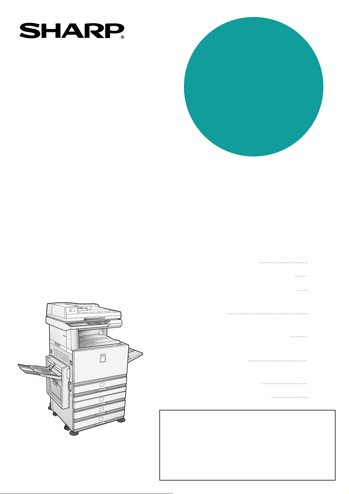
MODEL
AR-BC320
DIGITAL FULL COLOR MULTIFUNCTIONAL
SYSTEM
OPERATION MANUAL
(for general information and copier operation)
• BEFORE USING
THE PRODUCT
•
MANAGING THE MACHINE
• PERIPHERAL DEVICES
• BEFORE MAKING
COPIES
• BASIC PROCEDURE
FOR MAKING COPIES
• CONVENIENT COPY
FUNCTIONS
•
MACHINE MAINTENANCE
(FOR COPYING)
• SPECIFICATIONS
Page
1-1
2-1
3-1
4-1
5-1
6-1
7-1
8-1
(Option)
Duplex bypass / inverter unit and
Stand / 3 x 500 sheet paper drawer
Be sure to become thoroughly familiar with this manual to
gain the maximum benefit from the product.
Before installing this product, be sure to read the
installation requirements and cautions sections.
Be sure to keep all operation manuals handy for reference
including this manual, the "Operation manual (for general
information and copier operation)" and operation manuals
for any optional equipment which has been installed.
Page 2

The power switch positions are marked " I " to indicate power "ON" and " " to indicate stand-by.
In the stand-by position, power is being supplied to a drying heater within the optical system of the copier.
Caution:
For complete electrical disconnection, pull out the main plug.
The socket-outlet shall be installed near the equipment and shall be easily accessible.
FOR YOUR RECORDS ...
To protect against loss or theft, record and retain for reference the machine’s serial number located on the back
of the unit.
Model Number AR-BC320
Serial Number
Date of Purchase
Place of Purchase
Authorized Sharp Copier/Printer
Service Department Number
Warranty
While every effort has been made to make this document as accurate and helpful as possible, SHARP Corporation
makes no warranty of any kind with regard to its content. All information included herein is subject to change without
notice. SHARP is not responsible for any loss or damages, direct or indirect, arising from or related to the use of this
operation manual.
Copyright SHARP Corporation 2004. All rights reserved. Reproduction, adaptation or translation without prior
©
written permission is prohibited, except as allowed under copyright laws.
This operation manual is also used for the AR-BC320 J.
Page 3

Part 1: General Information
Page 4

Page 5

NOTES
● Considerable care has been taken in preparing this manual. If you have any comments or concerns about the
manual, please contact your nearest SHARP Service Department.
● This product has undergone strict quality control and inspection procedures. In the unlikely event that a defect
or other problem is discovered, please contact your dealer or nearest SHARP Service Department.
● Aside from instances provided for by law, SHARP is not responsible for failures occurring during use of the
product or its options, or failures due to incorrect operation of the product and its options, or other failures, or for
any damage that occurs due to use of the product.
The display screens, messages, and key names shown in the manual may differ from those on the actual machine
due to product improvements and modifications.
OPERATION MANUALS
The following operation manuals are provided for the machine. Please read the appropriate manuals as needed for
the features you wish to learn about.
●●●●
Operation manual (for general information and copier operation) (this manual):
The first half of this manual provides general information about the machine, including safety information, loading
paper, removing misfeeds, and regular maintenance.
The second half of the manual explains how to use the copy functions.
●●●●
Key operator's guide:
This primarily explains key operator programs for machine management and copier related functions. Key
operator programs for the printer, the facsimile and network scanner functions are explained in separate
manuals.
Key operator programs are used by key operators to configure function settings to meet the needs of the
customer.
●●●●
Operation manual (for facsimile):
This manual explains the procedures for using the machine as a facsimile. To use the fax function, the facsimile
expansion kit must be installed.
●●●●
Installation guide (for printer):
This explains how to connect the machine to your computer, install the printer driver for Windows, and configure
the printer driver settings.
●●●●
Operation manual (for printer)*:
This manual explains the procedures for using the machine as a printer.
●●●●
Operation manual (for network scanner)*:
This manual explains the procedures for using the machine as a network scanner when connected to a computer.
* The Operation manual (for printer) and the Operation manual (for network scanner) are provided as PDF files
on the supplied CD-ROM.
These manuals are not provided as printed manuals.
Some options may not be available in some countries and regions. This manual assumes that the optional
facsimile expansion kit has been installed, however, the basic operations of the machine are the same regardless
of the peripheral devices that are installed. For the peripheral devices that can be installed, see "Part names and
functions of peripheral devices" (1-6).
0-1
Page 6
INSTALLATION REQUIREMENTS
Improper installation may damage this product. Please note the following during initial installation and whenever the
machine is moved.
1. The machine should be installed near an accessible
power outlet for easy connection.
2. Be sure to connect the power cord only to a power
outlet that meets the specified voltage and current
requirements. Also make certain the outlet is
properly grounded.
● For the power supply requirements, see the
name plate on the main unit.
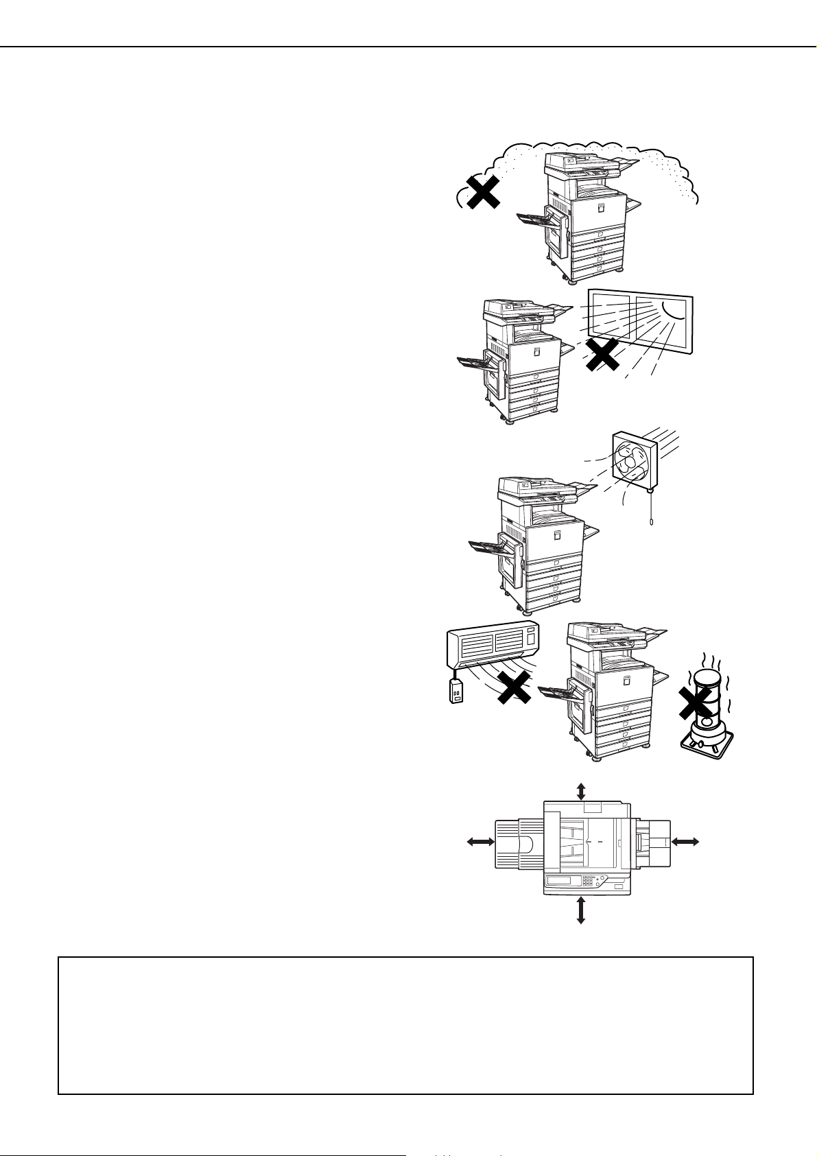
3. Do not install your machine in areas that are:
● damp, humid, or very dusty
● exposed to direct sunlight
● poorly ventilated
● subject to extreme temperature or humidity
changes, e.g., near an air conditioner or heater.
4. Be sure to allow the required space around the
machine for servicing and proper ventilation.
31-1/2"
(80cm)
11-13/16"
(30cm)
23-5/8"
(60cm)
23-5/8"
(60cm)
A small amount of ozone is produced within the copier during operation. The emission level is insufficient to cause
any health hazard.
NOTE:
3
The present recommended long term exposure limit for ozone is 0.1 ppm (0.2 mg/m
weighted average concentration.
However, since the small amount that is emitted may have an objectionable odor, it is advisable to place the copier
in a ventilated area.
) calculated as an 8 hr. time-
0-2
Page 7
INSTALLATION REQUIREMENTS
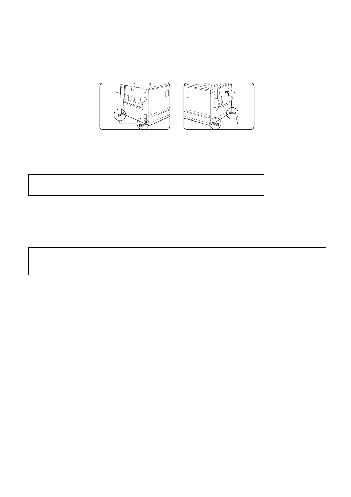
Moving this machine
Pull out the four handles as shown below, grasp them firmly, and keep the machine horizontal while moving it.
Left side Right side
Exit
tray
Handles
Before lifting the machine,
fold up the exit tray and
tape it securely to the
machine.
Caution
Two people are required to lift and carry this machine.
If the machine has been placed on a stand/paper drawer:
The stand/paper drawer is on casters for moving. Unlock the casters and the adjusters of the stand/paper drawer and
gently move the machine taking care to steady it to prevent it from toppling.
For locking and unlocking the casters and the adjusters, see page 0-4.
If the machine is to be left unused for a long time
If the machine is to be left unused for a month or longer, follow the procedure on pages 2-6 and 2-7 to release
the pressure on the fusing roller.
Before lifting the machine,
fold up the bypass tray
and tape it securely to the
machine.
Bypass
tray
Handles
0-3
Page 8
CAUTIONS
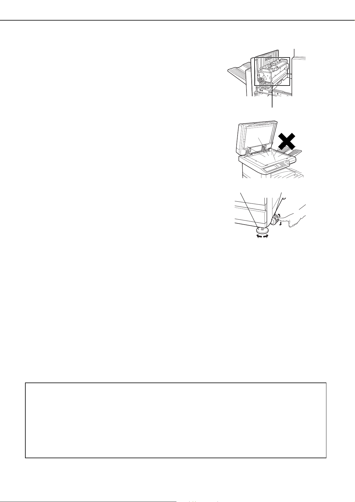
1. Do not touch the photoconductive drum. Scratches
or smudges on the drum will cause dirty prints.
2. The fusing unit is extremely hot. Exercise care in
this area.
3. Do not look directly at the light source. Doing so may
damage your eyes.
4. Four adjusters are provided on all optional stand/
paper drawer units. These adjusters should be
lowered until they contact the floor.
When moving the machine with the optional stand/
paper drawer, be sure to raise the adjusters. Also,
unlock the two casters at the front of the optional
stand/paper drawer. After moving the machine,
lower the four adjusters until they reach the floor and
lock the two casters.
Fusing unit
5. Do not make any modifications to this machine.
Doing so may result in personal injury or damage to
the machine.
6. Since this machine is heavy, it is recommended that
it be moved by more than one person to prevent
injury.
7. When connecting this machine to a computer, be
sure to first turn both the computer and the machine
off.
8. Do not make copies of anything which is prohibited
from copying by law. The following items are
normally prohibited from printing by national law.
Other items may be prohibited by local law.
●
Money ● Stamps ● Bonds ● Stocks
●
Bank drafts ● Checks ● Passports
●
Driver's licenses
Adjuster
Lock
Caster
Release
Lock
Release
"BATTERY DISPOSAL"
THIS PRODUCT CONTAINS A LITHIUM PRIMARY MEMORY BACK-UP BATTERY THAT MUST BE
DISPOSED OF PROPERLY. PLEASE CONTACT YOUR LOCAL SHARP DEALER OR AUTHORIZED SERVICE
REPRESENTATIVE FOR ASSISTANCE IN DISPOSING OF THIS BATTERY.
This product utilizes tin-lead solder, and a fluorescent lamp containing a small amount of mercury.
Disposal of these materials may be regulated due to environmental considerations.
For disposal or recycling information, please contact your local authorities or the Electronics Industries Alliance:
www.eia.org
0-4
Page 9

CONTENTS
OPERATION MANUALS.................................................0-1
INSTALLATION REQUIREMENTS.................................0-2
● Moving this machine..................................................0-3
CAUTIONS......................................................................0-4
CHAPTER 1
BEFORE USING THE PRODUCT
INTRODUCTION.............................................................1-2
MAIN FEATURES ...........................................................1-2
PART NAMES AND FUNCTIONS ..................................1-4
● Exterior......................................................................1-4
● Interior .......................................................................1-5
● Part names and functions of peripheral devices........1-6
● Operation panel.........................................................1-8
● Touch panel...............................................................1-9
AUDITING MODE .........................................................1-11
● Using the machine when the auditing mode is
enabled ...................................................................1-11
CHAPTER 2
MANAGING THE MACHINE
LOADING PAPER...........................................................2-2
● Loading paper in paper tray 1....................................2-2
● Changing the paper size in paper tray 1....................2-2
● Loading paper in the bypass tray ..............................2-4
● Loading paper in the stand/1 x 500 sheet paper drawer/
stand/3 x 500 sheet paper drawer.............................2-7
● Specifications (stand/1 x 500 sheet paper drawer/
stand/3 x 500 sheet paper drawer)............................2-7
● Loading paper in the duplex module/2 x 500 sheet
paper drawer .............................................................2-8
● Specifications (duplex module/2 x 500 sheet paper
drawer) ......................................................................2-8
● Specifications of paper trays .....................................2-9
● Setting the paper type (except the bypass tray)......2-11
● Setting the paper size when an extra size is loaded2-11
● Setting the paper type and paper size in the bypass
tray...........................................................................2-12
CUSTOM SETTINGS....................................................2-13
● Operation procedure common to all custom settings
.................................................................................2-13
● About the settings....................................................2-14
REPLACING THE TONER CARTRIDGES ...................2-15
STORAGE OF SUPPLIES ............................................2-17
MISFEED REMOVAL....................................................2-18
● Misfeed removal guidance.......................................2-18
● Misfeed in the paper feed area................................2-19
● Misfeed in the transport area, fusing area, and exit
area .........................................................................2-20
● Misfeed in the stand/1 x 500 sheet paper drawer....2-21
● Misfeed in the stand/3 x 500 sheet paper drawer....2-21
● Misfeed in the duplex bypass/inverter unit and duplex
module/2 x 500 sheet paper drawer........................2-22
TROUBLESHOOTING..................................................2-24
CHAPTER 3
PERIPHERAL DEVICES
SADDLE STITCH FINISHER ......................................... 3-2
● Part names and functions ......................................... 3-2
● Specifications............................................................ 3-2
● Saddle stitch finisher functions ................................. 3-4
● Using the saddle stitch finisher................................. 3-6
●
Staple cartridge replacement and staple jam removal
● Misfeed in the saddle stitch finisher........................ 3-10
● Troubleshooting saddle stitch finisher problems..... 3-12
● Stapling position quick reference guide for duplex
output...................................................................... 3-13
● Relation between print image and saddle stitch ..... 3-14
LARGE CAPACITY TRAY............................................ 3-15
● Part name ............................................................... 3-15
● Specifications.......................................................... 3-15
● Loading paper in the large capacity tray................. 3-16
● Misfeed in the large capacity tray ........................... 3-17
.. 3-7
0-5
Page 10

CONTENTS
CHAPTER 4
BEFORE MAKING COPIES
PART NAMES AND FUNCTIONS (The Reversing Automatic
Document Feeder)
● Exterior ..................................................................... 4-2
● Operation Panel........................................................ 4-3
● Touch Panel (main screen of copy mode) ................ 4-4
REVERSING AUTOMATIC DOCUMENT FEEDER....... 4-5
● Acceptable originals.................................................. 4-5
SETTING ORIGINALS ................................................... 4-6
SELECTING THE ORIGINAL SIZE................................ 4-8
STORING, DELETING, AND USING ORIGINAL SIZES
........................................................... 4-2
........ 4-9
CHAPTER 5
BASIC PROCEDURE FOR MAKING
COPIES
NORMAL COPYING....................................................... 5-2
● Copying from the reversing automatic document feeder
.................................................................................. 5-2
● Automatic two-sided copying from the reversing
automatic document feeder ...................................... 5-6
● Copying from the document glass ............................ 5-7
● Automatic two-sided copying from the document glass
.................................................................................. 5-9
EXPOSURE ADJUSTMENTS...................................... 5-10
REDUCTION/ENLARGEMENT/ZOOM ........................ 5-12
● Automatic selection (auto image) ........................... 5-12
● Manual selection..................................................... 5-13
● XY ZOOM ............................................................... 5-15
SPECIAL PAPERS....................................................... 5-17
IMAGE EDIT MENU ..................................................... 6-16
● Single color .............................................................6-17
● Mirror image ............................................................ 6-17
● Photo Repeat ..........................................................6-18
● Multi shot................................................................. 6-19
● 11" x 17" (A3) Full-bleed ......................................... 6-21
● Multi-page enlargement .......................................... 6-22
● Pamphlet copy ........................................................ 6-24
JOB PROGRAM MEMORY.......................................... 6-25
● Storing a job program.............................................. 6-25
● Recalling a job program .......................................... 6-26
● Deleting a stored job program................................. 6-26
INTERRUPTING A COPY RUN ................................... 6-27
CHAPTER 7
MACHINE MAINTENANCE (FOR
COPYING)
REMOVING AN ORIGINAL MISFEED........................... 7-2
● Removing a misfed original from the reversing automatic
document feeder ....................................................... 7-2
USER MAINTENANCE (For copying) ............................ 7-3
TROUBLESHOOTING.................................................... 7-4
CHAPTER 8
SPECIFICATIONS
SPECIFICATIONS.......................................................... 8-2
● Copier and Main unit................................................. 8-2
● Reversing automatic document feeder ..................... 8-4
● Duplex bypass/inverter unit (optional)....................... 8-4
INDEX............................................................................. 8-5
CHAPTER 6
CONVENIENT COPY FUNCTIONS
SPECIAL MODES .......................................................... 6-2
● Common operation procedure for using the special
functions ................................................................... 6-3
● Margin shift ............................................................... 6-4
● Erase ........................................................................ 6-5
● Dual page copy......................................................... 6-6
● Centering .................................................................. 6-7
● Transparency film with insert sheets ........................ 6-8
● Covers ...................................................................... 6-9
● B/W reverse ............................................................ 6-10
COLOR ADJUSTMENTS MENU.................................. 6-11
● RGB adjust ............................................................. 6-12
● Sharpness............................................................... 6-13
● Suppress background............................................. 6-13
● Color balance.......................................................... 6-14
● Brightness............................................................... 6-15
● Intensity .................................................................. 6-15
0-6
Page 11

CHAPTER 1
BEFORE USING THE
PRODUCT
This chapter contains basic information that should be read before using
the product.
Page
INTRODUCTION ...........................................................................................1-2
MAIN FEATURES..........................................................................................1-2
PART NAMES AND FUNCTIONS .................................................................1-4
●
Exterior...................................................................................................1-4
●
Interior....................................................................................................1-5
●
Part names and functions of peripheral devices ....................................1-6
●
Operation panel......................................................................................1-8
●
Touch panel ...........................................................................................1-9
AUDITING MODE ........................................................................................1-11
●
Using the machine when the auditing mode is enabled.......................1-11
1-1
Page 12
INTRODUCTION
To gain the maximum benefits in using this product, it is recommended that the user read this manual to become
familiar with all the features and functions of the basic product and the precautionary information contained in the
manual.
This product is a high speed Digital full color copier / printer that can be expanded to become multifunctional through
the installation of optional peripheral devices. The product can be extended to include printer, network scanning or
network printing capabilities. This manual describes the basic use of the product as a copier and does not contain
information on using any of the optional peripheral devices. Separate operation manuals are included with each of
the optional peripheral devices. Refer to these manuals for their operation.
Original and paper sizes
This machine allows use of standard sizes in both the inch and AB systems.
These are shown in the tables below.
Sizes in the inch system
11" x 17" (LEDGER)
8-1/2" x 14" (LEGAL)
8-1/2" x 13" (FOOLSCAP)
8-1/2" x 11" (LETTER)
7-1/4" x 10-1/2" (EXECUTIVE)
5-1/2" x 8-1/2" (INVOICE)
Sizes in the AB system
A3
B4
A4
B5
A5
The meaning of "R" in original and paper size indications
Some original and paper sizes can be placed in either the portrait or landscape orientations. To differentiate between
landscape and portrait, the landscape orientation size indication will contain an "R". These are indicated as 8-1/2" x
11"R, 5-1/2" x 8-1/2"R, A4R, B5R, etc. Sizes that can be placed only in the landscape orientation (11" x 17", 8-1/2"
x 14", 8-1/2" x 13", A3, B4) do not contain the "R" in their size indication.
Size indication with "R"
Landscape orientation
Size indication without "R"
Portrait orientation
MAIN FEATURES
Full-color copies with vivid colors based on digital technology
1
Photos, color text, and other originals are scanned by full-color CCD sensors, and the acquired image
information is output in vivid full color at a resolution of 600 dpi using digital image processing technology.
The machine can also be used as a full-color network printer, and network scanner.
A range of optional units to enhance productivity
2
A range of optional equipment is available to enhance productivity, such as duplex units for producing two-sided
output, additional paper feed units to increase the number of available paper sizes and paper capacity, and
paper output units that are capable of stapling and saddle stitch binding.
1-2
Page 13
MAIN FEATURES
Advanced image processing features based on digital technology
3
The scanned image data is converted to digital data, enabling the following advanced image processing features:
●●●● Photo Repeat :
Up to 24 full-size copies of a photo image can be made on a single sheet of paper (page 6-18).
●●●● Multi shot :
Up to four original pages can be copied onto a single sheet (page 6-19).
●●●● Pamphlet copy* :
Copies of original pages are arranged in proper order for copying so that the copies can be center-stapled and
folded into a pamphlet (page 6-24).
* Pamphlet copy requires the Duplex module/2 x 500 sheet paper drawer and Duplex bypass/inverter unit
options. If a saddle stitch finisher is installed, copies can be stapled in two positions along the center of copies
and folded at the center.
Image processing manual exposure adjustment for optimal copying
4
Image processing is optimized for the type of original being copied (text, photo, mixed text and photo or map). This
along with the ability to manually adjust exposure makes it possible to obtain copies that are faithful to the original.
Standard offset function makes it easy to distinguish between sets of copies
5
As sets of copies are delivered to the center tray, each set is offset from the previous set for easy separation.
1
PostScript compatible
6
Installation of an optional PS expansion kit (AR-PK4) gives PostScript compatibility (PostScript 3).
®
As an ENERGY STAR
®
ENERGY STAR
guidelines for energy efficiency.
Partner, SHARP has determined that this product meets the
Energy saving features
This product has the following two power reducing modes to help conserve natural resources and reduce
environmental pollution.
Preheat mode
Preheat mode automatically reduces the temperature of the fusing unit after the time set in the key operator
programs elapses when the machine is on standby. This allows the machine to use less power while on
standby. The machine automatically returns to normal operation when a key is pressed on the operation
panel, or when an original is placed to make a copy or send a fax.
Auto power shut-off mode
Auto power shut-off mode automatically shuts off power to the fusing unit after the time set in the key
operator programs elapses when the machine is on standby. This minimizes the power used by the
machine while on standby. When this mode activates, the touch panel screen turns off.
To return the machine to normal operation, press the mode select key (the indicator of this key will be lit).
Auto power shut-off mode can be configured in the key operator programs. The mode is initially set (factory
default setting) to activate after 60 seconds elapses. (See page 9 of the key operator's guide.)
If a print job or fax is received while auto power shut-off mode or preheat mode is activated, the machine
automatically returns to normal operation.
The Environmental Choice Program guidelines are applied to the products only in Canada. The
products that meet the Environmental Choice Program guidelines carry the logo shown above.
The products without the logo may not meet the Environmental Choice Program guidelines.
1-3
Page 14
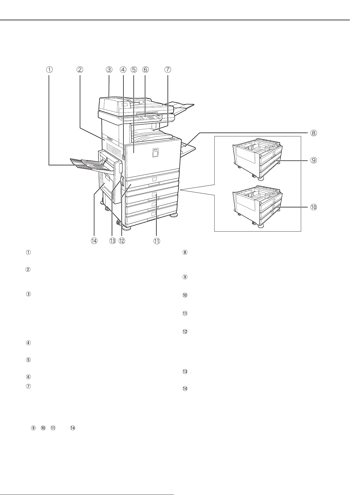
PART NAMES AND FUNCTIONS
Exterior
Left tray (See page 5-5)
Finished sheets are deposited here.
Left side cover
Open this cover when a paper misfeed occurs in
the fusing unit or the transfer unit.
Reversing automatic document feeder
(See page 4-2)
This automatically feeds originals to be scanned.
The feeder can turn the original over and scan the
back side as well as the front side for support of
two-sided originals.
Power switch
Press to turn power on and off.
Front cover
Open to replace toner cartridge.
Operation panel
Center tray (See page 5-5)
Finished sheets are deposited here.
Bypass tray
Special papers (including transparency film) and
copy paper can be fed from the bypass tray.
Stand/1 x 500 sheet paper drawer*
(See page 2-7)
Stand/3 x 500 sheet paper drawer*
(See page 2-7)
Duplex module/2 x 500 sheet paper drawer*
(See page 2-8)
Paper tray
Each tray can hold approximately 500 sheets of the
recommended paper for color (21 lbs. or 80 g/m
or approximately 500 sheets of SHARP standard
paper (21 lbs. or 80 g/m
Left side cover release
Push this release up to open the left side cover.
Duplex bypass/inverter unit and exit tray* (See
page 1-6)
2
).
2
),
* , , and are peripheral devices. For a description of these devices, see page 1-6.
1-4
Page 15
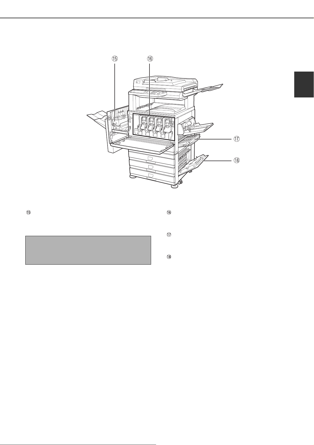
Interior
PART NAMES AND FUNCTIONS
1
Fusing unit
Toner images are fused here.
CAUTION
The fusing unit is hot. Take care in removing misfed
paper.
Toner cartridge
The toner cartridge must be replaced when
indicated on the operation panel. (See page 2-15)
Right side cover
Open when a misfeed has occurred in the paper
feed area.
Right cover of paper drawer
Open this cover to remove paper misfed in the
paper drawer.
1-5
Page 16
PART NAMES AND FUNCTIONS
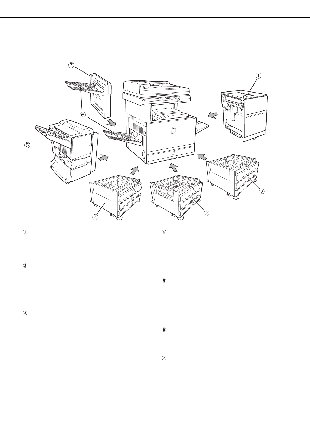
Part names and functions of peripheral devices
Large Capacity tray (AR-LC8)
The large capacity tray provides the added
convenience of having 3,500 sheets of 8-1/2" x 11"
or A4 paper (21 lbs. or 80 g/m
2
) available.
Stand/1 x 500 sheet paper drawer (AR-D17N)
This stand has one paper tray. It can hold
approximately 500 sheets of the recommended
paper for color (21 lbs. or 80 g/m
2
), or
approximately 500 sheets of SHARP standard
2
paper (21 lbs. or 80 g/m
).
Duplex module/2 x 500 sheet paper drawer (AR-D19N)
This stand includes a module for automatic twosided printing and two paper trays. The two trays
can hold approximately 500 sheets of the
recommended paper for color (21 lbs. or 80 g/m
2
or approximately 500 sheets of SHARP standard
2
paper (21 lbs. or 80 g/m
). To perform two-sided
printing, a duplex bypass/inverter unit (AR-RB1) is
required.
Stand/3 x 500 sheet paper drawer (AR-D18N)
This stand has three paper trays. Each tray can
hold approximately 500 sheets of the
2
recommended paper for color (21 lbs. or 80 g/m
),
or approximately 500 sheets of SHARP standard
2
paper (21 lbs. or 80 g/m
).
Saddle stitch finisher (AR-F13)
The finisher can deliver sets saddle stitched and
folded at the paper centerline to form a pamphlet,
edge stapled in three different modes or unstapled.
For two-hole or three-hole output, a hole punch
module must be installed.
Exit tray (AR-TE3)
),
The exit tray is installed on the output outlet of the
machine or the duplex tray / inverter unit.
Duplex bypass/inverter unit (AR-RB1)
This module is required to automatically turn paper
over within the machine for automatic two-sided
printing.
1-6
Page 17

■■■■ Other optional equipment
PART NAMES AND FUNCTIONS
●●●●PS3 expansion kit (AR-PK4)
This kit provides compatibility of PostScript level 3
to the printer.
●●●●Facsimile expansion kit (AR-FX10)
This kit must be installed to use the fax function.
●●●●Fax memory (8 MB) (AR-MM9)
This adds memory for use by the fax function.
●●●●256 MB optional memory (AR-SM5)
This adds memory that is used for the copy
function, printer function, and scanner function.
■■■■ Face-up and face-down output
After printing, the paper is delivered to the exit tray. This product has two exit trays (center tray and left tray). The
paper specifications (page 8-3) and output conditions differ for each tray; however, if the paper and output
conditions are such that the paper can be delivered to either tray, you can select the tray to which the paper will
go.
● Paper exits to the center tray face-down only.
● Paper exits to the left tray face-up only. However, if a duplex bypass/inverter unit has been installed, face-
down output is also possible. In this case, face-up or face-down output is automatically selected according to
the paper and output conditions (it is not possible to manually select face-up or face-down.)
1
1-7
Page 18
PART NAMES AND FUNCTIONS
Operation panel
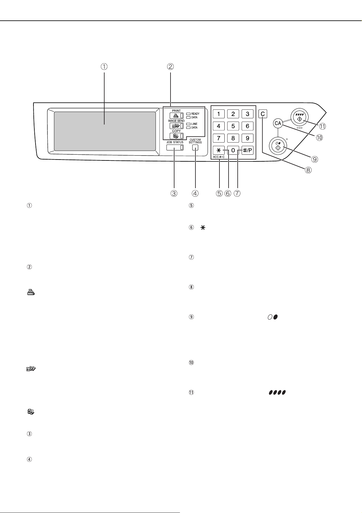
Touch panel
The machine status, messages and touch keys are
displayed on the panel. When using the touch
panel, first change the display to the mode that you
wish to use: printer mode, copy mode, network
scanner mode, or fax mode*. For details see the
next page.
Mode select keys and indicators
Use to change modes and the corresponding
display on the touch panel.
[PRINT] key/READY indicator/DATA indicator
Press to enter the printer mode.
READY indicator
Print data can be received when this indicator is
lit.
DATA indicator
Lights up or blinks when print data is being
received. Also lights up or blinks when printing is
being performed.
[IMAGE SEND] key/LINE indicator/DATA
indicator
Press this key to switch the display between
network scanner mode and fax mode*. (See the
operation manuals for network scanner and fax.)
[COPY] key
Press to select the copy mode.
Numeric keys
Use to enter number values for various settings.
[ ] key ([ACC.#-C] key)
This is used when the copy, network scan, and fax*
functions are used.
[#/P] key
This is used as a program key when using the copy
function, and to dial when using the fax function*.
[C] key
This key is used in copy mode, network scanner
mode, and fax mode*.
[BLACK COPY START ( )] key
This is used to make black and white copies and to
scan a black and white original when the network
scan function is used. This is also used to scan an
original to be faxed using the fax function*.
[CA] key
This key is used in copy mode, network scanner
mode, and fax mode*.
[COLOR COPY START ( )] key
This is used to make full-color or single-color
copies and to scan a color original when the
network scanner function is used.
[JOB STATUS] key
Press to display the current job status. (See page
1-10.)
[CUSTOM SETTINGS] key
Use to adjust the contrast of the touch panel or to
set key operator programs. (See page 2-13.)
1-8
* When the fax option is installed.
Page 19
Touch panel
JOB QUEUE
COPY
Suzuki
0666211221
003 / 00
003 / 00
010 / 00
SETS / PRO
1/13
COMPLETE
CANCEL OK
RIGHT
BINDING
LEFT
BINDING
TRANSPARENCY
INSERTS
DUAL PAGE
COPY
SPECIAL MODES
2-SIDED COPY
OUTPUT
READY TO COPY.
B4
P
OR
A3
A4
DUPLEX
PART NAMES AND FUNCTIONS
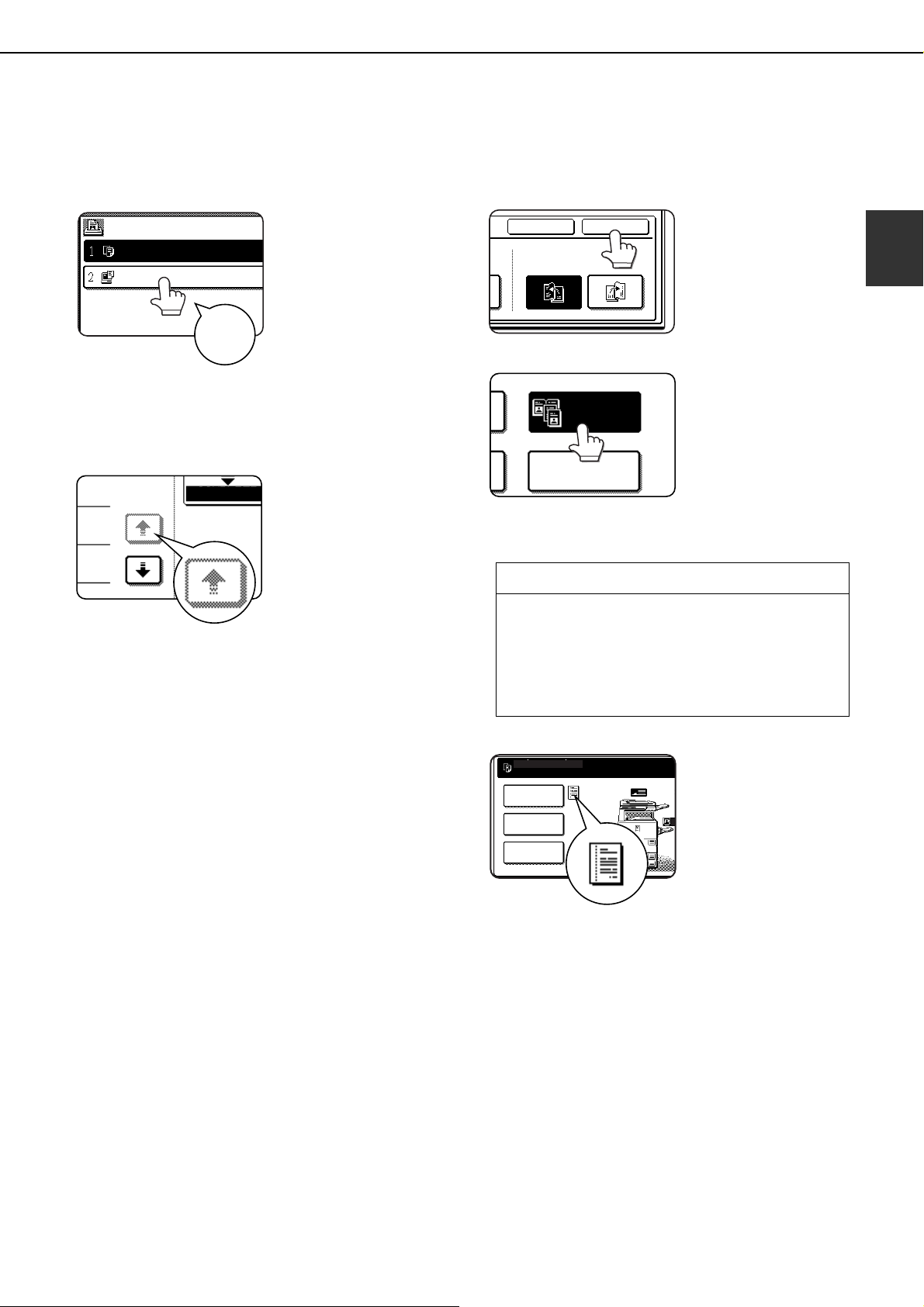
Using the touch panel
[Example 1]
Items on the touch panel
are easily selectable by
touching the key
associated with the item
with a finger. Selection
of an item will be
Beep
tone
[Example 2]
The confirmation beeps can be disabled by a key
operator program. (See page 10 of the key
operator's guide.)
accompanied with a
beep tone to confirm the
item was selected. Also,
the key area for the item
will be highlighted for
visual confirmation.
Keys which are grayed
out on any screen are
not selectable. If a
grayed out key is
touched, a double beep
will be sounded.
Selection of function
[Example 1]
[Example 2]
Copier feature
● Dual page copy
● Centering
● Transparency inserts
● Mirror image
● 11"x17" (A3) Full-bleed
● B/W Reverse
Items which are
highlighted at the time a
screen appears are
already selected and will
be registered to function if
the [OK] key is touched.
When the machine is
used in the copy mode,
the functions shown in
the table below can only
be set or canceled on
the special feature
screen by alternate
touches of the function
keys on the panel.
1
The touch panel screens shown in this manual are
printed images, and may appear different from the
actual screens.
[Example 3]
When the machine is
used in the copy mode
and a special feature is
selected, a
corresponding icon
representing the feature
will appear on the touch
key and on the main
screen of the mode
selected. If this icon is
touched, the setting
screen of the function (or
a menu screen) will
appear, allowing the
settings to be checked
or adjusted and the
function to be canceled
easily.
1-9
Page 20
PART NAMES AND FUNCTIONS
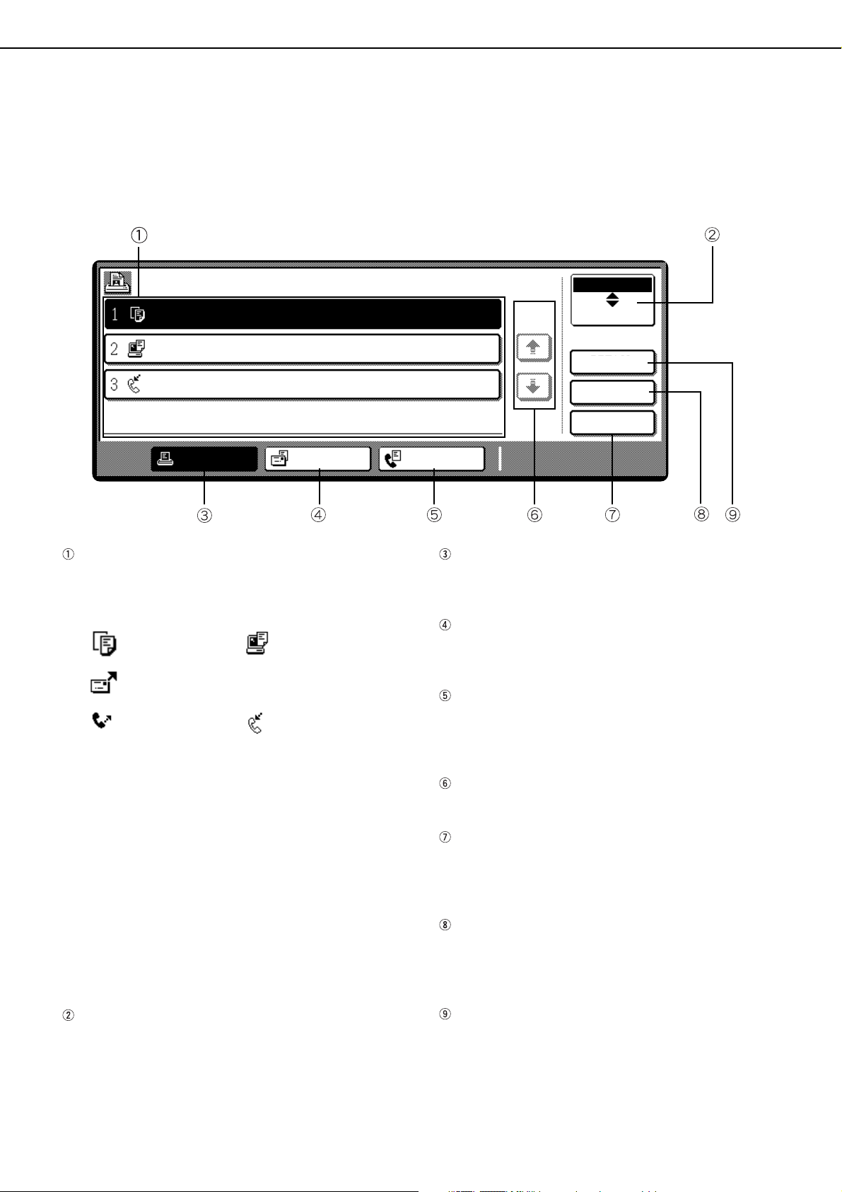
Job status screen (common to print, copy, network scan and fax)
This screen is displayed when the [JOB STATUS] key on the operation panel is pressed.
A job list showing the current job at the top of the job queue or a list showing completed jobs can be displayed.
The contents of jobs can be viewed or jobs can be deleted from the queue. (The screen below is an example and
differs from actual screens.)
JOB QUEUE
COPY
Suzuki
066211221
PRINT JOB SCANNER JOB
Job list
This shows the current job and the jobs waiting to
be run. The icons to the left of the jobs in the queue
show the job mode.
Copy mode Printer mode
Network scanner mode
Fax send job Fax reception job
The displayed jobs in the job list are themselves
operation keys. To cancel printing or to give a job
the highest print priority, touch the relevant job key
to select the job and execute the desired operation
using the keys described in 5 and 6.
* "PAPER EMPTY" in the job status display
When a job status display indicates "PAPER
EMPTY", the specified paper size for the job is not
loaded in any of the trays.
When the [DETAIL] key appears, the key of a job in
the job queue can be touched followed by the
[DETAIL] key to change the paper size selection to
a different paper size (only in printer mode).
SETS / PROGRESS
003 / 000
003 / 000
001 / 000
STATUS
PAPER EMPTY
WAITING
WAITING
FAX JOB
[PRINT JOB] key
Use to display the print job list for printer, copy and
fax mode.
[SCANNER JOB] key
This displays a list of jobs that only used the
network scanner function.
[FAX JOB] key
This displays the transmission/reception status
and finished jobs of fax mode when the fax option
is installed.
Display switching keys
Use to switch the page of the displayed job list.
[STOP/DELETE] key
Use to cancel or delete the current job or delete the
selected reserved job. Note that a fax print job
cannot be canceled or deleted.
[PRIORITY] key
This only appears in the job status screen of fax
mode. Touch this key to give priority to a job that
has been selected in the job queue.
JOB QUEUE
1/1
*
COMPLETE
DETAIL
PRIORITY
STOP/DELETE
Mode select key
This only appears in the job status screen of fax
mode. The key is used to switch the job list display
between "JOB QUEUE" and "COMPLETE".
"JOB QUEUE": Shows stored jobs and the job in
progress.
"COMPLETE" : Shows finished jobs.
1-10
[DETAIL] key
The key is only effective for computer print jobs and
only appears in the job status screen of the printer
mode. It is used to display detailed information of a
selected print job and to change the paper size for
the print job.
Page 21
AUDITING MODE
ENTER YOUR ACCOUNT NUMBER.
ENTER YOUR ACCOUNT NUMBER FOR THE COLOR MODE.
PRESS [CANCEL] TO CHANGE TO B/W MODE.
CANCEL
When the account counter function is turned on, a count is kept of the number of copy sheets used by each account
(maximum of 200 accounts). The counts can be displayed and totaled as needed.
The key operator programs can be used to enable auditing mode separately for copy mode, fax mode, network
scanner mode and printer mode. (Page 6 of key operator's guide)
Using the machine when the auditing mode is enabled
The procedure for using the machine for copying functions when the Auditing Mode has been enabled for the copier
functions is explained below.
NOTES
● When the account counter is turned on for fax or network scanner functions, a message will appear prompting
you to enter your account number each time the touch panel is changed to the main screen of the function. Enter
your account number as explained below and then proceed with the job.
● When the account counter is turned on for the printer function, you must enter your account number in the setting
screen of the printer driver on your computer in order to print.
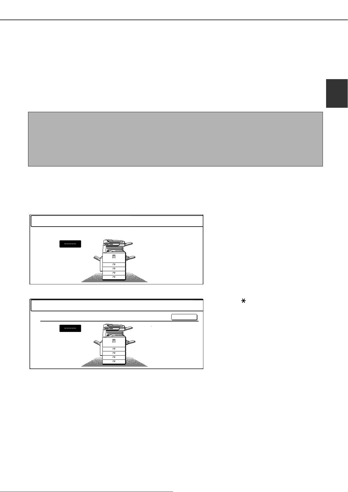
When the account counter is turned on, the following messages appear on the touch panel. There are two types of
prompts, depending on whether the account counter was turned on for both the color copy and the black and white
copy modes, or only for color copy mode.
●Account counter enabled for both the color copy and the black and white copy modes
1
●The account counter is enabled only for the color copy mode
AUDITING MODE FOR COLOR
In this case, enter your 5-digit account number as explained on the next page to gain access to the copier functions.
When the [ ] key ([ACC.#-C] key) or the
[COLOR COPY START] key is pressed, the
message at left appears.
1-11
Page 22

AUDITING MODE
Enter your account number (5 digits) with
1
the numeric keys.
As you enter your
account number, the
hyphens ( ) change to
asterisks ( ). If you
enter an incorrect digit,
press the key and reenter the correct digit.
When a correct account
number is entered, the
following message will
appear.
ACCOUNT STATUS:COPIES MADE/REMAINING
B/W
S.COLOR
F.COLOR
This does not appear if the account counter
has only been set for color copy mode.
If a limit has been set by key operator program
for the number of copies that can be made by
the account, the remaining number that can be
made is displayed.
This message appears for several seconds and
then changes to the following message.
Follow the appropriate steps to perform
2
the copy job.
When copying is begun, the following message
will appear.
READY TO COPY.
PRESS [ACC.#] WHEN FINISHED.
In the case of interrupt copying (page 6-27), the
following message will appear.
READY TO COPY. WHEN INTERRUPT COPYING
IS FINISHED PRESS [CANCEL].
When the copy job is finished, press the
3
[ ] key ([ACC.#-C] key)
READY TO COPY.
NOTE
If "Account number security" is turned on in the key
operator programs, the following message will
appear in the event that an incorrect account number
is entered three times in a row. (Page 8 of the key
operator's guide)
PLEASE SEE YOUR KEY OPERATOR FOR
ASSISTANCE.
While this message appears (for about one minute),
no other operations can be performed.
1-12
Page 23

CHAPTER 2
MANAGING THE MACHINE
This chapter explains how to load paper, replace the toner cartridge,
and remove paper misfeeds. It also contains information about supplies.
Page
LOADING PAPER..........................................................................................2-2
●
Loading paper in paper tray 1 ................................................................2-2
●
Changing the paper size in paper tray 1 ................................................2-2
●
Loading paper in the bypass tray...........................................................2-4
●
Loading paper in the stand/1 x 500 sheet paper drawer/stand/3 x 500
sheet paper drawer..................................................................................... 2-7
●
Specifications (stand/1 x 500 sheet paper drawer/stand/3 x 500
sheet paper drawer)...............................................................................2-7
●
Loading paper in the duplex module/2 x 500 sheet paper drawer .........2-8
●
Specifications (duplex module/2 x 500 sheet paper drawer) .................2-8
●
Specifications of paper trays ..................................................................2-9
●
Setting the paper type (except the bypass tray)...................................2-11
●
Setting the paper size when an extra size is loaded ............................2-11
●
Setting the paper type and paper size in the bypass tray ....................2-12
CUSTOM SETTINGS ..................................................................................2-13
●
Operation procedure common to all custom settings...........................2-13
●
About the settings ................................................................................2-14
REPLACING THE TONER CARTRIDGES..................................................2-15
STORAGE OF SUPPLIES...........................................................................2-17
MISFEED REMOVAL ..................................................................................2-18
●
Misfeed removal guidance ...................................................................2-18
●
Misfeed in the paper feed area ............................................................2-19
●
Misfeed in the transport area, fusing area, and exit area.....................2-20
●
Misfeed in the stand/1 x 500 sheet paper drawer................................2-21
●
Misfeed in the stand/3 x 500 sheet paper drawer................................2-21
●
Misfeed in the duplex bypass/inverter unit and duplex module/2 x 500
sheet paper drawer ..............................................................................2-22
TROUBLESHOOTING.................................................................................2-24
2-1
Page 24
LOADING PAPER
The message "ADD PAPER" or "OPEN TRAY AND ADD PAPER" will appear when paper runs out during operation.
Follow the procedure below to load paper.
NOTES
● Do not use curled or folded paper. Doing so may cause a misfeed.
● For best results use paper supplied by SHARP. (See pages 2-9, 2-17.)
● When you change the paper type and size in paper tray 1, you must change the paper type and size settings as
explained in "Setting the paper type" (page 2-11).
● Do not place heavy objects or press hard on any tray which is pulled out.
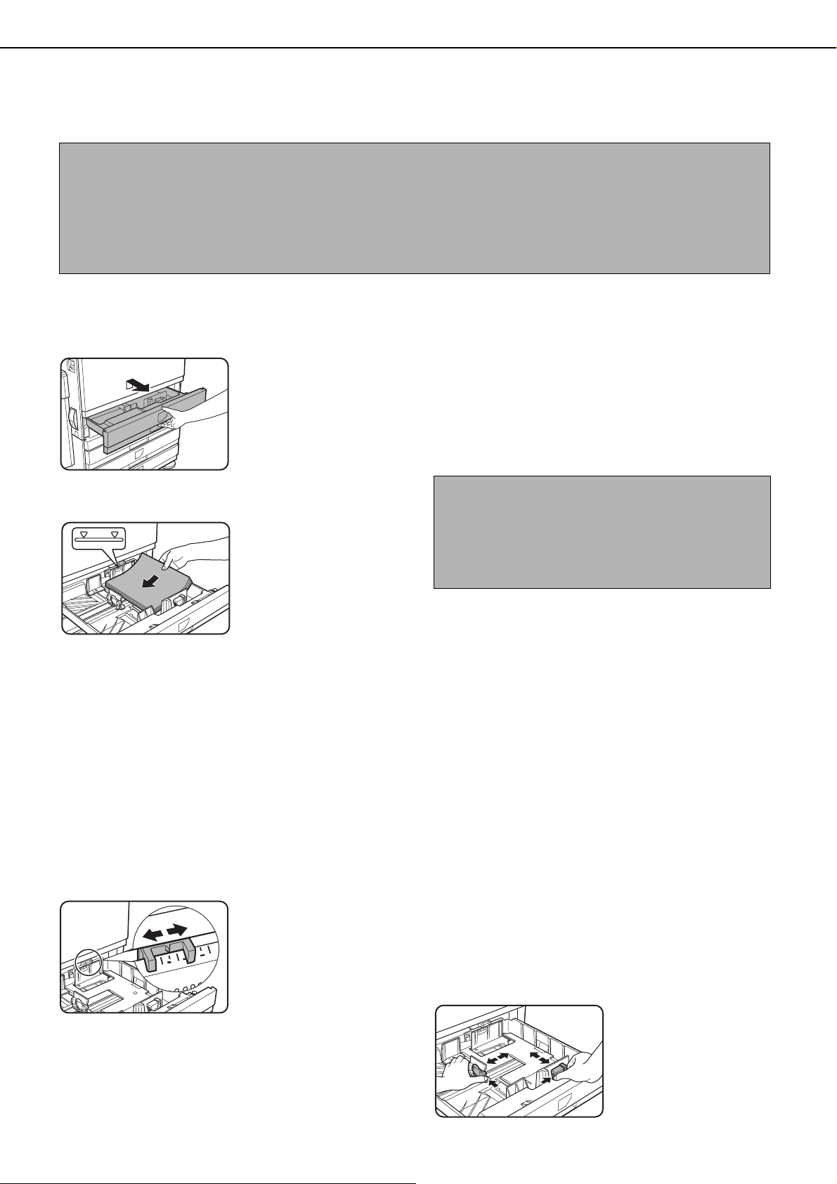
Loading paper in paper tray 1
Pull out paper tray 1.
1
Load paper into the tray.
2
Gently pull the tray out
until it stops.
Load a stack of paper no
higher than the indicator
line (about 500 sheets of
the recommended paper
for color (21 lbs. or 80 g/
2
m
), or approximately
500 sheets of SHARP
standard paper (21 lbs.
or 80 g/m
2
)).
Gently push tray 1 into the machine.
3
Push the tray firmly all the way into the machine.
Set the paper type.
4
If you change the paper type, be sure to set the
paper type refer to "Setting the paper type" (page
2-11).
NOTE
If you load a different size of the same type of paper,
you only need to change the position of the size slide
(see step 2 below); you do not need to change the
paper type.
Loading paper in paper tray 1 is now
5
complete.
Changing the paper size in paper tray 1
The following paper size settings are available for paper tray1: 11" x 17" to 8-1/2" x 5-1/2" (A3 to A5), and "EXTRA"*1.
Use the following procedure to change the size as needed.
1
This is limited to square or rectangular paper, 11" x 17" to 8-1/2" x 5-1/2" (A3 to A5) size.
*
Pull out paper tray 1.
1
If paper remains in the tray, remove it.
Adjust the paper size slide to the paper
2
size.
Move the paper size
slide right or left to
indicate the paper size
being loaded.
If a special size paper is
loaded in the paper tray,
set the size slide to
"EXTRA" to inform the machine that a special size
paper has been loaded. (When AB-based size
paper is loaded, move the size slide to "EXTRA".)
2-2
Note that setting the size slide to "EXTRA" only
informs the machine that a special size of paper
has been loaded; it does not inform the machine of
the specific size. If you wish to inform the machine
of the specific size, follow the steps in "Setting the
paper size when an extra size is loaded" (page 2-
11). (If you do not set a size, part or all of the image
may not print.)
Adjust the guide plates A and B by
3
squeezing their lock levers and sliding
them to the paper size to be loaded.
The guide plates A and
B are slidable. Adjust
them to the paper size to
be loaded while
squeezing their lock
levers.
Page 25
LOADING PAPER
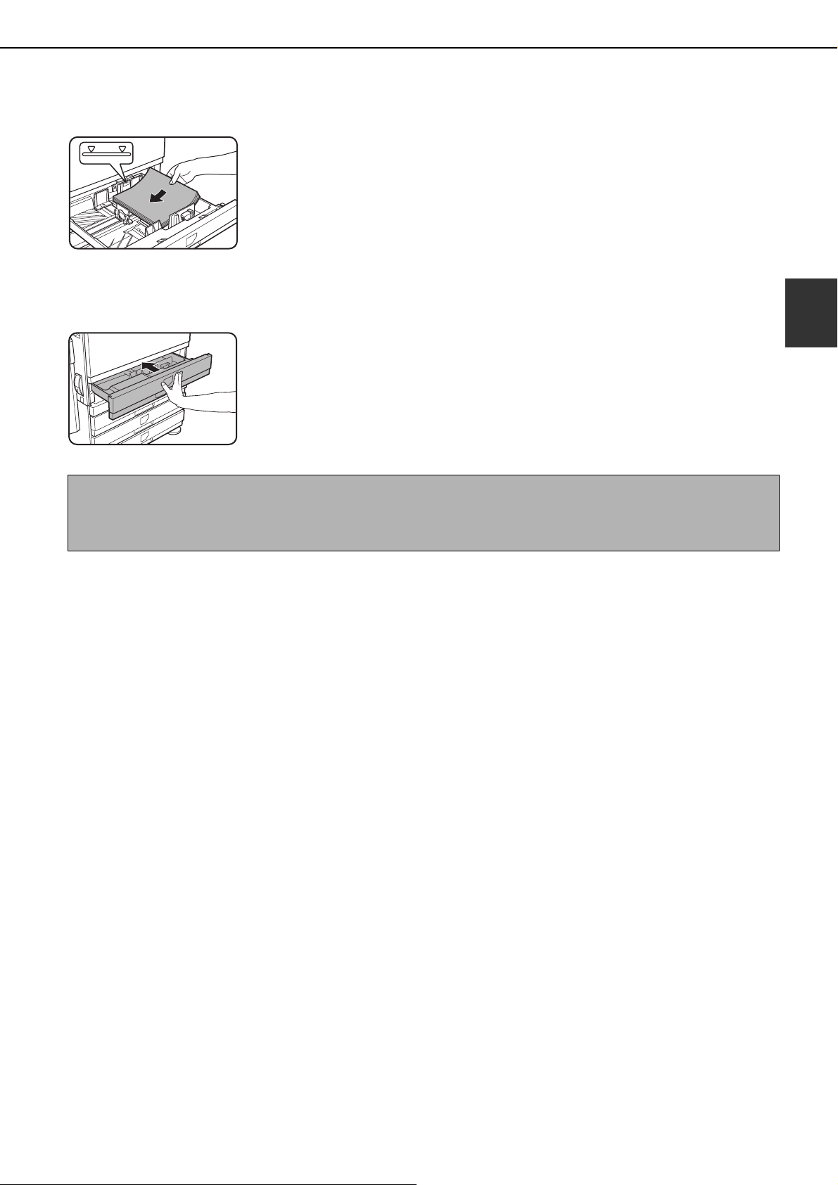
Load paper into the tray.
4
Gently push tray 1 into the machine.
5
Push the tray firmly all
the way into the
machine.
NOTE
If the size slide position (step 2 of page 2-2) is not set correctly after changing the paper size, or if the paper type
(page 2-11) is not set correctly, incorrect paper selection or paper misfeeding may occur.
Set the paper type of the paper that was
6
loaded in the 1st tray.
If you loaded a different type of paper from the
previous paper, be sure to set the new paper type
as explained in "Setting the paper type" (page 2-
11).
Changing paper size in paper tray 1 is now
7
complete.
2
2-3
Page 26
LOADING PAPER
Loading paper in the bypass tray
The bypass tray can be used to feed the same paper specified for paper tray 1 or for special papers. For paper types
that can be used in the bypass tray, see the specifications for the bypass tray in the paper tray specifications (page
2-9).
Up to 250 sheets of SHARP standard paper or up to 100 postcards can be set in the bypass tray.
NOTES
● After loading the paper in the bypass tray, be sure to set the paper type and size (step 4) if these were changed.
● Do not use inkjet paper. This may cause misfeeds in the fusing unit.
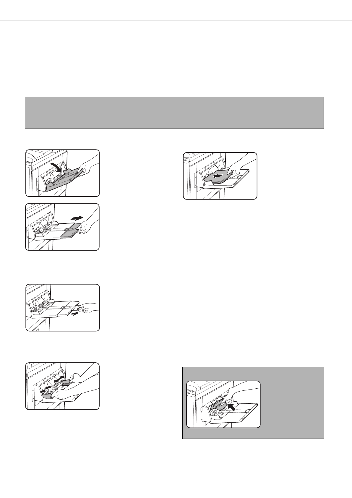
Open the bypass tray.
1
When loading paper that
will extend past the end
of the tray, pull out the
tray extension to support
the paper and to allow the
paper sensors to properly
sense the paper size.
Be sure to pull the tray extension all the way out. If
the tray extension is not pulled all the way out, the
size of the paper loaded in the bypass tray may not
display correctly.
To support papers that
extend past the tray
extension, pull out the
wire extension.
Insert the copy paper all the way into the
3
bypass tray. (Do not force the paper in.)
Place the copy paper
face up. If the bypass
tray guides are set
wider than the copy
paper, the inside of the
machine may become
soiled, resulting in
smudges on succeeding copies. Special purpose
papers other than SHARP recommended
transparency film must be fed individually. Multiple
sheets of SHARP recommended transparency
film can be loaded in the bypass tray.
Set the type and size of the paper loaded in
4
the bypass tray.
If you loaded a different type of paper from the
previous paper, be sure to set the new paper type
as explained in "Setting the paper type and paper
size in the bypass tray" (page 2-12). If you loaded
a special size of paper in the bypass tray, set the
paper size as explained in "Setting the paper type
and paper size in the bypass tray" (page 2-12).
(If you do not set a size, part or all of the image
may not print.)
Set the bypass tray guides to the width of
2
the copy paper.
2-4
This completes the procedure for loading
5
paper in the bypass tray.
NOTE
When loading paper in
the bypass tray or
closing the tray, close
the paper cover as
shown.
Page 27
NOTES
● Be sure to load 5-1/2" x 8-1/2" paper, A6 paper, A5
paper, and postcards as shown in the diagram
below.
LOADING PAPER
A6 paper, post cards.
5-1/2" x 8-1/2" paper, A5 paper.
● When loading plain paper other than paper
recommended for color, SHARP standard paper,
special media other than postcards, SHARPrecommended transparency film, or paper to be
printed on the back, the paper must be loaded one
sheet at a time. Loading more than one sheet at a
time will cause misfeeds.
● Before loading heavy paper, straighten any curling
in the paper.
● When adding paper, remove any paper remaining
in the tray, combine it with the paper to be added,
and reload as a single stack.
● Do not use paper that has already been printed on
by a plain paper fax machine or a laser printer.
This may cause printed images to become dirty.
● When printing on transparency film, be sure to
remove each sheet as it exits the machine.
Allowing sheets to stack in the output tray may
cause curling.
● Use only SHARP-recommended transparency
film. Insert the film so that the rounded corner is on
the left for horizontal loading, or on the right for
vertical loading.
2
Horizontal
loading
● When loading multiple sheets of transparency film
in the bypass tray, fan the sheets several times
before loading.
Vertical
loading
2-5
Page 28
LOADING PAPER
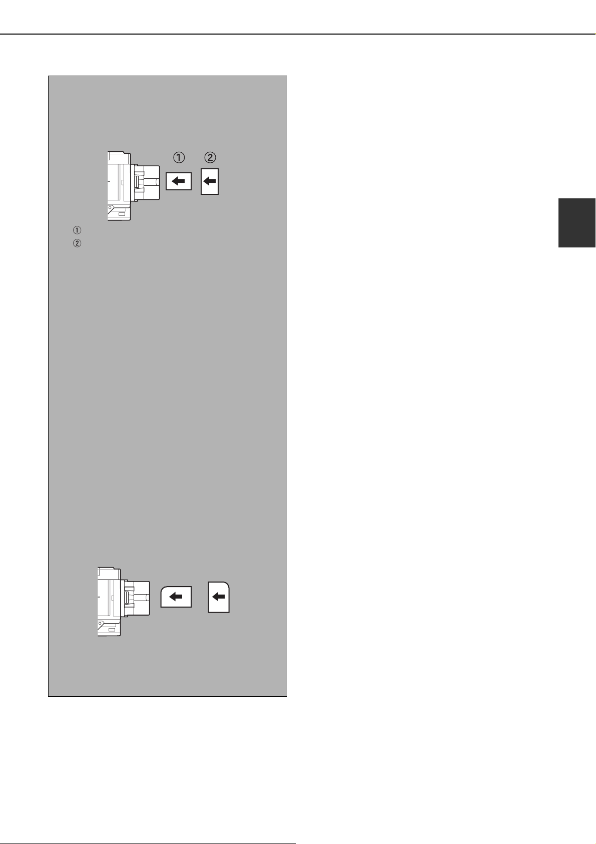
■■■■ Setting envelopes or postcards
When setting envelopes or postcards in the bypass tray, set them in the orientation shown below.
Loading postcards
Insert the postcard with the side to be printed on
facing up. The postcard should be oriented as
shown in the diagram.
Loading envelopes
Only the front side of envelopes can be printed.
Insert the envelope with the front side facing up.
Printing onto envelopes or postcards
●Attempting to print onto both sides of envelopes or postcards may result in misfeeds or poor prints.
●Do not use pre-printed envelopes.
●Before inserting a postcard or envelope, straighten any curled edges. Curled edges may cause creases, color
deviations, misfeeds, and poor quality images.
Printing onto envelopes
●Attempting to print on envelopes that have metal clasps, plastic snaps, string closures, windows, linings, selfadhesive patches or synthetic materials may cause misfeeds, inadequate toner adherence or other trouble.
●Envelopes with embossed surfaces may cause the prints to become smudged.
●Use only envelopes which are flat and crisply folded. Curled or poorly formed envelopes may be poorly printed
or may cause misfeeds.
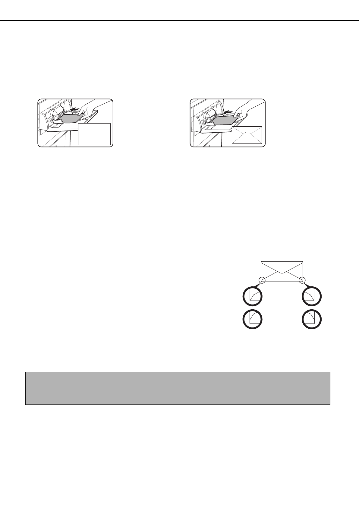
●Print quality is not guaranteed in the area 13/32" or 10 mm from the
edges of the envelope.
●Print quality is not guaranteed on parts of envelopes where there is a
large step-like change of thickness, such as on three-layer or four-layer
envelopes.
●Print quality is not guaranteed on envelopes having peel off flaps for
sealing the envelopes.
Can be used
Cannot be used
Fusing unit pressure adjusting levers
In some cases damage to the envelopes, color deviations, or smudging may occur even if envelopes within the
specifications are used. This problem may be reduced by shifting the fusing unit pressure adjusting levers from
their normal pressure position to the lower pressure position. Follow the procedure on the next page. (2-7)
NOTE
Be sure to return the lever to the normal position when you have finished feeding envelopes. If not, inadequate
toner adherence, paper misfeeds or other trouble may occur.
2-6
Page 29
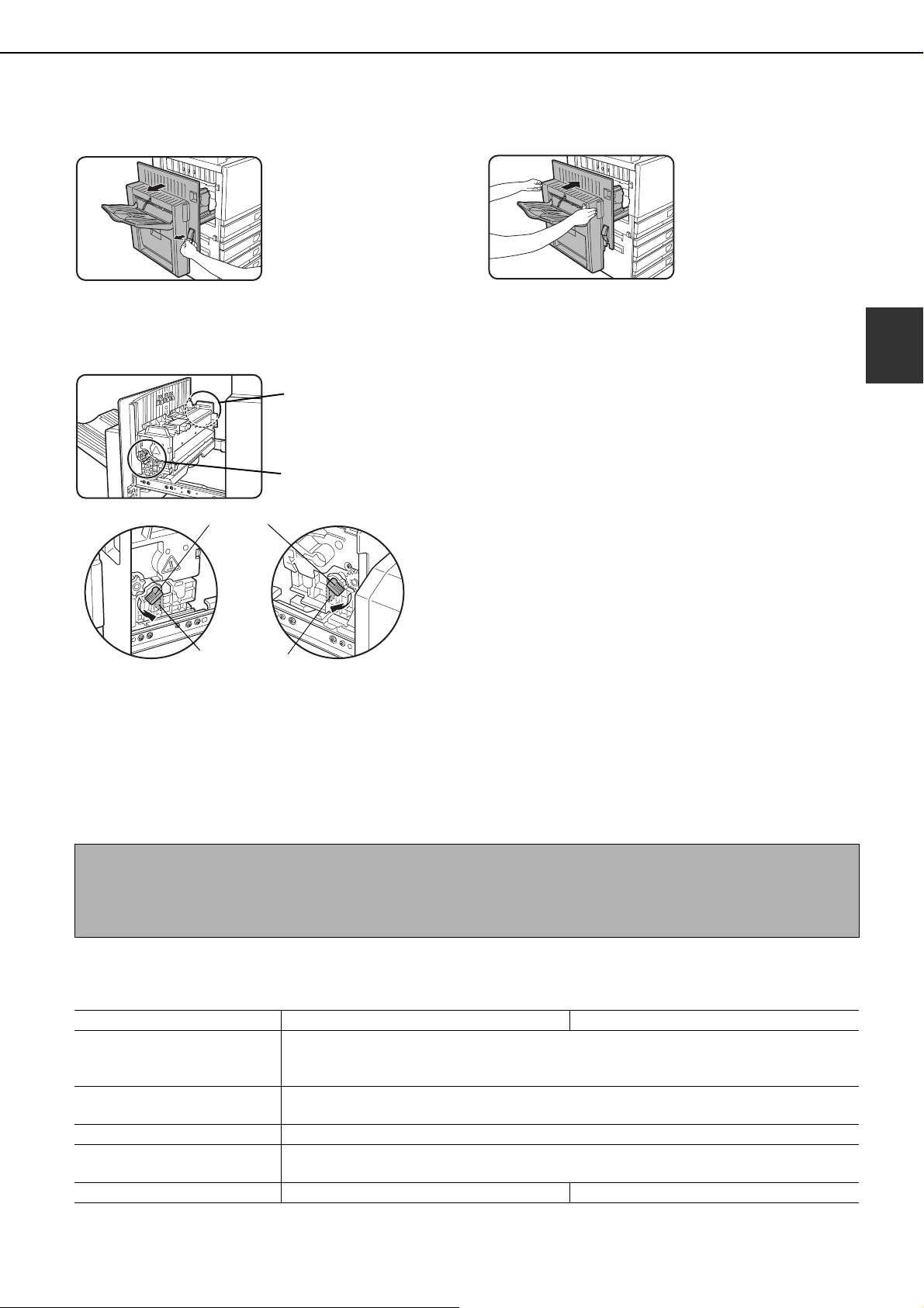
LOADING PAPER
Unlatch the duplex bypass/inverter unit
1
and slide it to the left.
Unlatch the unit and
gently move it away from
the machine. If the
machine is not equipped
with a duplex bypass/
inverter unit, open the
side cover similarly.
Lower the two fusing unit pressure
2
adjusting levers marked A and B in the
illustration.
A
B
Normal
position
Gently close the duplex bypass/inverter
3
unit.
If the machine is not
equipped with a duplex
bypass/inverter unit,
close the side cover.
2
B:Front side of
fusing unit
Lower pressure
position
A:Rear side of
fusing unit
Loading paper in the stand/1 x 500 sheet paper drawer/ stand/3 x 500 sheet paper drawer
Upper tray / middle tray / lower tray*
Up to 500 sheets of paper recommended for color or SHARP recommended plain paper can be loaded in these trays.
The method of loading paper is the same as for paper tray 1 in the main unit (see the explanation on page 2-2).
* The stand/1 x 500 sheet paper drawer only has the upper tray.
NOTE
If the size of paper being loaded is different from the previous size, or is an extra size, or if the paper type is different
from the previous type, you must change the paper tray settings in the custom settings. Change the settings as
explained in "Setting the paper type" and "Setting the paper size when an extra size is loaded" on page 2-11.
Specifications (stand/1 x 500 sheet paper drawer/stand/3 x 500 sheet paper drawer)
Name
Paper size/weight
Paper capacity
Power supply Supplied from the main unit
Dimensions
Weight Approximately 49.6 lbs. or 22.5 kg Approximately 65.0 lbs. or 29.5 kg
Specifications are subject to change for improvement without notice.
Stand/1 x 500 sheet paper drawer (AR-D17N) Stand/3 x 500 sheet paper drawer (AR-D18N)
11" x 17", 8-1/2" x 14", 8-1/2" x 13", 8-1/2" x 11", 8-1/2" x 11"R, 7-1/4" x 10-1/2"R,
5-1/2" x 8-1/2", Extra. (A3, B4, A4, A4R, B5, B5R, A5)
/ 17 to 28 lbs. or 64 to 105 g/m
Paper recommended for color (21 lbs. or 80 g/m
SHARP standard paper (21 lbs. or 80 g/m
23-5/8" (W) x 25-9/32" (D) x 15-7/8" (H) (600 mm (W) x 642 mm (D) x 403 mm (H))
(not including the adjuster)
2
2
): 500 sheets;
2
): 500 sheets
2-7
Page 30
LOADING PAPER
Loading paper in the duplex module/2 x 500 sheet paper drawer
Upper tray:
The upper tray contains a duplex module that automatically turns print paper over for automatic two-sided printing.
Middle and lower paper trays:
The middle and lower trays are paper trays.
Up to 500 sheets of paper recommended for color or SHARP recommended plain paper can be loaded in these trays.
The method of loading paper is the same as for paper tray 1 in the main unit. See the explanation on page 2-2.
NOTE
If the size of paper being loaded is different from the previous size, or is an extra size, or if the paper type is different
from the previous type, you must change the paper tray settings in the custom settings. Change the settings as
explained in "Setting the paper type" and "Setting the paper size when an extra size is loaded" on page 2-11.
Specifications (duplex module/2 x 500 sheet paper drawer)
Name Duplex module/2 x 500 sheet paper drawer (AR-D19N)
11" x 17", 8-1/2" x 14", 8-1/2" x 13", 8-1/2" x 11", 8-1/2" x 11"R, 7-1/4" x 10-1/2"R,
Paper size/weight
Paper capacity
Power supply Supplied from the main unit
Dimensions
Weight Approximately 68.3 lbs. or 31 kg
Duplex module
Size of plain paper
Weight of plain paper 17 to 54 lbs. or 64 to 200 g/m
Number of sheets One sheet (single pass type)
Specifications are subject to change for improvement without notice.
5-1/2" x 8-1/2", Extra. (A3, B4, A4, A4R, B5, B5R, A5)
/ 17 to 28 lbs. or 64 to 105 g/m
Paper recommended for color (21 lbs. or 80 g/m
SHARP standard paper (21 lbs. or 80 g/m
23-5/8" (W) x 25-9/32" (D) x 15-7/8" (H) (600 mm (W) x 642 mm (D) x 403 mm (H))
11" x 17", 8-1/2" x 14", 8-1/2" x 13", 8-1/2" x 11", 8-1/2" x 11"R, 7-1/4" x 10-1/2R",
5-1/2" x 8-1/2", A3, B4, A4, A4R, B5, B5R, A5
2
2
): 500 sheets
(not including the adjuster)
2
2
): 500 sheets;
2-8
Page 31

LOADING PAPER
Specifications of paper trays
The specifications for the types and sizes of paper that can be loaded in the paper trays are shown below.
Tray No.
Paper tray type
A Paper tray 1 Tray 1
B Bypass tray
Stand/1 x 500
C
sheet paper drawer
Stand/3 x
500 sheet
D
paper
drawer
Duplex
module/2 x
E
500 sheet
paper
drawer
F
Large Capacity tray
Upper Tray 2
Middle Tray 3
Lower Tray 4
Upper Duplex
Middle Tray 2
Lower Tray 3
(tray
name)
Bypass
tray
Tray 2
Tray 4*1
or
Tray 5*
Applicable paper types Applicable paper sizes Remarks
11"x17", 8-1/2"x14",
8-1/2"x13", 8-1/2"x11",
Paper recommended for color
Plain paper
Same as paper types and sizes in row A
* Paper size 12" x 18" (A3W) and A6R can also be used in the bypass tray
Heavy
paper 1
Special
paper (Refer
to the next
page for
applicable
special
papers.)
Same as paper types and sizes in row A
Duplex module
(See page 2-8 for paper sizes and weights that can be used.)
Same as paper types and sizes in row A
Same as paper types in row A 8-1/2"x11" (A4)
2
Heavy
paper
Heavy
paper 2
Transparency film Transparency film
Envelopes
8-1/2"x11"R, 5-1/2"x8-1/2",
7-1/4"x10-1/2"R, Extra. (A3,
B4, A4, A4R, B5, B5R, A5)
11"x17", 8-1/2"x14",
8-1/2"x13", 8-1/2"x11",
8-1/2"x11"R, 5-1/2"x8-1/2",
7-1/4"x10-1/2"R, Extra. (A3,
B4, A4, A4R, B5, B5R, A5)
5-1/2"x8-1/2" - 12"x18" (A6R
- A3W), Special (paper
weight: 28 to 54 lbs. (106 to
200 g/m
5-1/2"x8-1/2" - 12"x18" (A6R
- A3W), Special (paper
weight: 54 to 80 lbs. (201 to
300 g/m
●Standard-size envelopes
2
)), Postcard
2
))
that can be used
:COM10,Monarch,DL,C5
See
"STORAGE
OF
SUPPLIES"
on page 2-17
See "More
information on
plain paper"
on the next
page
See "More
information on
special media
that can be
used" on the
next page
See the
specifications
in "LARGE
CAPACITY
TRAY" on
page 3-15, and
"More
information on
plain paper" on
the next page.
2
*1 When the Duplex module/2 x 500 sheet paper drawer is installed.
*2 When the Stand/3 x 500 sheet paper drawer is installed.
2-9
Page 32

LOADING PAPER
■■■■ More information on plain paper
The following restrictions apply to plain paper. Be sure to load the paper correctly. Incorrect loading may result
in skewed feeding or misfeeds.
Paper in inch system Paper in AB system
5-1/2"x8-1/2" - 12"x18"* A6R - A3W*
Plain
paper
SHARP standard
paper
Restrictions on paper
other than SHARP
21 lbs. 80g/m
17 to 28 lbs. or 64 to 105g/m
2
2
standard paper
Recycled, colored, pre-punched, pre-printed and letterhead papers must conform to the same conditions as
above.
* In the large capacity tray, only 8-1/2" x 11" size paper can be used when using inch sizes, and only A4 can be
used when using AB sizes.
■■■■ More information on special media that can be used
The following restrictions apply to special media. The use of incorrect media may result in fusing problems (weak
adhesion of toner to paper or toner smudging when rubbed), skewed feeding, misfeeds, or other failures.
Type Remarks
For paper sizes from 5-1/2" x 8-1/2" to 12" x 18" (A6R to A3W),
2
) can be used.
2
) can be used.
Special
paper
Heavy
paper
heavy paper 1
heavy paper 2
paper weights from 28 to 54 lbs. (106 to 200 g/m
● Postcards can be used.
Do not use folded postcards, picture postcards, or postcards with
a coated front. These may cause misfeeds or a dirty printed
image.
For paper sizes from 5-1/2" x 8-1/2" to 12" x 18" (A6R to A3W),
paper weights from 54 to 80 lbs. (201 to 300 g/m
Transparency film Use SHARP recommended transparencies.
Applicable standard envelopes: COM-10, Monarch, DL, C5
Envelopes
Envelopes can only be fed from the Bypass tray. Applicable paper
stock weight for envelopes is 20 to 23 lbs. or 75 to 90 g/m
2
● Special paper such as heavy paper 2, transparency film, and envelopes cannot be output to the center tray.
● Paper that cannot be output to the center tray is output face-up to the left tray.
■■■■ Paper that can be used for automatic two-sided printing
Paper used for automatic two-sided printing (paper that can be fed through the duplex module) must meet the
following conditions:
Paper type : Plain paper as specified on page above.
Paper size : Must be one of the following standard sizes: 11" x 17", 8-1/2" x 14", 8-1/2" x 13", 8-1/2" x 11",
8-1/2" x 11"R, 7-1/4" x 10-1/2" or 5-1/2" x 8-1/2" (A3, B4, A4, A4R, B5, B5R or A5)
Paper weight : 17 to 54 lbs. or 64 to 200 g/m
2
NOTES
● Special papers as described above cannot be used for automatic two-sided printing. Heavy paper up to 54 lbs.
2
(200 g/m
) can be used.
● The image quality and toner fusibility of special papers may change due to ambient conditions, operating
conditions, and paper characteristics, resulting in image quality inferior to that of SHARP standard paper.
● Various types of plain paper and special paper are sold. Some of these cannot be used in the machine. Please
consult your retailer or your dealer when buying paper.
2-10
Page 33

LOADING PAPER
TOT L COUNT
TRAY SETTINGS
KEYBOARD
SELECT
KEY
ADDRES
CONTRO
CONTRA
TRAY 1
TRAY 2 PLAIN /
TYPE / SIZE
PLAIN /
PLAIN
PRE-PRINTED
RECYCLED
LETTER HEAD
PRE-PUNCHED
COLOR
Setting the paper type (except the bypass tray)
Follow these steps to change the paper type setting
when the paper type has been changed in a paper tray.
For the paper types that can be used in each tray, see
page 2-9. To change the paper type setting for the
bypass tray, see page 2-12.
Press the [CUSTOM SETTINGS] key.
1
The custom setting
menu screen will
appear.
Touch the [TRAY SETTINGS] key.
2
The paper tray selection
screen will appear.
Setting the paper size when an extra size is loaded
When a paper tray is set to "extra", this informs the
machine that an extra size is being used. It does not
inform the specific size. To enter the specific size of the
paper loaded, follow the steps below.
For example, if A4 size paper is loaded in the tray (with
the size slide set to "extra"), you can use this procedure
to set the paper size recognized by the machine to A4
size. If you loaded an irregular size of paper, you can
enter the dimensions of the paper.
To set the paper size when an extra size of paper is
loaded in the bypass tray, see page 2-12.
Perform steps 1 through 4 of "Setting the
1
paper type" at left.
Touch the key to display the paper size
2
setting screen.
CUSTOM SETTINGS
TRAY 3 TYPE/SIZE SETTING
EXTRA SIZE
A3 B4
B5R
11X17
1
/
5 X8
2
A5
1
/
8 X14
2
1
1
/
7 X10 R
4
1
/
2
/
2
A4
8K
1
/
8 X13
2
EXTRA
A4R
16K
1
/
2
8 X11
8 X11R
B5
16KR
1
/
2
OK
2/3
2
Select the paper tray for which the setting
3
is to be made. (For the tray numbers, see
the tray specifications on page 2-9.)
If the desired tray is not
on the display, use or
key to scroll the
display until it appears.
Select the type of paper that was loaded in
4
the tray.
The currently selected
paper type will be
highlighted. To change
the setting, touch the
desired type.
NOTE
Special paper such as transparency film,
envelopes, and postcards can only be used in the
bypass tray.
When the loaded paper size appears in the
3
display (if you loaded an AB-based size
such as A4), touch the size key to highlight
it, and then touch the [OK] key to complete
the procedure.
If an irregular size of paper was loaded
4
after the [EXTRA] key was touched, touch
the key in the screen of step 2 to display
the following screen.
(5 1/2 17)
1
/
5
X
Y
When the screen opens the X key will be
highlighted. Use the
enter the X dimension. Next touch the Y key to
highlight it and enter the dimensions for Y.
The permitted range for the X dimension is 5-1/2 to
17 inches (139 to 432 mm), and the permitted
range for the Y dimension is 7-1/4 to 11-3/4 inches
(182 to 297 mm).
When both have been entered, touch the [OK] to
complete the operation.
2
1
7
4
/
inch
(7 1/4 11 3/4)
inch
and
touch keys to
Touch the [OK] key to complete the
5
setting.
2-11
Page 34

LOADING PAPER
PAPER SELECT
AUTO 8½x11
100%
PAPER SELECT
8½x11
PAPER SELECT
100%
COPY RATIO
PLAIN
HEAVY PAPER
TRANSPARENCY
ENVELOPE
UTO
EXPOSURE
PAPER SELECT
PLAIN
HEAVY PAPER
TRANSPARENCY
ENVELOPE
Setting the paper type and paper size in the bypass tray
Follow the steps below to set the type and size of the paper loaded in the bypass tray.
Touch the [PAPER SELECT] key.
1
(When copy mode is selected)
Touch the [PAPER
SELECT] key in the
main screen of the copy
mode.
(When printer mode is selected)
Touch the [PAPER
SELECT] key in the
main screen of printer
mode.
CONDITION
SETTINGS
Touch the key for the desired paper type.
2
(When copy mode is selected)
The key for the selected
paper type will be
highlighted.
Touch [HEAVY PAPER 1] or [HEAVY
3
PAPER 2], and go to step 6.
HEAVY PAPER1 28+lbs. 54 lbs.
HEAVY PAPER2 54+lbs. 80 lbs.
For the types of heavy paper that can be used, see
page 2-10.
Touch [SPEED MODE] or [QUALITY MODE]
4
for the transparency film, and go to step 7.
SPEED MODE
QUALITY MODE
● SPEED MODE is for fast printing.
● QUALITY MODE is for a high quality image.
Touch the type of envelope, and go to step 7.
5
COM-10
MONARCH
DL
YOKEI-2
OK
C5
CHOKEI3
YOKEI-4
(When printer mode is selected)
The steps that follow differ depending on the
paper type selected. Follow the steps for the
selected type.
● If you touched [PLAIN], go to step 6.
● If you touched [HEAVY PAPER], go to step 3
● If you touched [TRANSPARENCY], go to step 4.
● If you touched [ENVELOPE], go to step 5.
2-12
CONDITION
SETTINGS
If you inserted a non-standard size of paper
6
in the bypass tray, remove the checkmark
from "ENABLE AUTO SIZE DETECTION" and
then touch the [EXTRA SIZE] tab.
When the
screen opens, the X key will be highlighted.
Use the and
touch keys to enter the X
dimension. If you inserted a standard size of
paper in the bypass tray, make sure that a
checkmark appears in the [ENABLE AUTO
SIZE DETECTION] checkbox.
ENABLE AUTO SIZE DETECTION
EXTRA SIZE
OK
(5 1/2 17)
5 ½
X
Y
EXTRA SIZE
inch
(4 11 3/4)
4
inch
BASIC SETTING
range for the Y dimension is 4 to 11-3/4 inches
(100 to 297 mm).
Touch the [OK] key to complete the setting.
7
BASIC SETTING
Next touch the key to
highlight it and enter the
dimensions for Y.
The permitted range for
the X dimension is 5-1/2
to 17 inches (139 to 432
mm), and the permitted
Page 35

CUSTOM SETTINGS
The items that can be set with the custom settings are shown below.
● Total count ................................... The number of pages processed by the machine and optional equipment
can be displayed. (See page 2-14.)
● Display contrast ........................... Used to adjust the contrast of the operation panel display. (See page 2-14.)
● List print ....................................... Used to print a list of machine settings. (See page 2-14.)
● Clock adjust
● Tray settings ................................ The paper type, paper size and automatic tray switching can be set for each
For the detailed descriptions and use of the settings listed below, see the Operation manuals
for fax* and network scanner.
● Address control............................ Use this to store fax destinations (fax numbers). This is also used to store
● Receive mode.............................. Use this to configure fax reception settings (auto/manual).
● Fax data forward.......................... Faxes received to memory can be forwarded to another destination.
● Keyboard select........................... When using the fax function or network scanner function, you can switch
● Key operator program.................. These are programs that are used by the key operator (administrator of the
* These fax settings can be configured only if the fax function has been enabled.
....................................Used to set the date and time of the built-in clock of the machine. (See this page.)
tray. Automatic tray switching allows feeding to switch between trays
loaded with the same type and size of paper. If one tray runs out of paper
during printing, printing will continue from the other tray. (
See
page 2-14)
groups, memory boxes, and user indexes.
E-mail addresses, user indexes, and scanner senders can be stored for the
network scanner function.
the arrangement of the letter keys in the display keyboard used for storing
and editing destinations in the English character entry screen.
machine) to configure machine settings. A key appears for these settings in
the custom settings menu screen. For information on these settings, see
the key operator's guide.
2
Operation procedure common to all custom settings
Press the [CUSTOM SETTINGS] key.
1
The custom setting
menu screen will
appear.
More information on setting procedures
In the following type of screen, a setting is turned
on when a checkmark ( ) appears next to the
key. A checkmark will appear or disappear by
alternate touches of the checkmark box. In the
following screen, tray 1 can be used in print, copy,
and fax modes. Tray 2 can only be used in the
copy mode.
CUSTOM SETTINGS
TRAY SETTINGS
TRAY 1
TRAY 2 PLAIN /
TYPE / SIZE
PLAIN /
PRINT
COPY
OK
FAX
1/2
Touch the key of the desired item to
2
display its setting screen.
The settings accessed by touching the [CLOCK]
key are explained here.
CUSTOM SETTINGS
TOTAL COUNT
TRAY SETTINGS
KEYBOARD
SELECT
DISPLAY
CONTRAST
ADDRESS
CONTROL
KEY OPERATOR PROGRAMS
LIST PRINT
RECEIVE MODE
Detailed descriptions for program settings start on
the next page.
The procedure for setting the clock is shown below
as an example.
CUSTOM SETTINGS
CLOCK ADJUST
YEAR
2004
DAYLIGHT SAVING TIME SETTING
MONTH
11
DAY
HOUR
MINUTE
01
00
00
DATE FORMAT
EXIT
CLOCK
FAX DATA
FORWARD
OK
2-13
Page 36

CUSTOM SETTINGS
Touch the year, month, day, hour or
3
minute key, and then use the or key
to adjust the setting.
● If you select a non-existent date (for example, Feb.
30), the [OK] key will gray out to prevent entry of the
date.
● Select [DAYLIGHT SAVING TIME SETTING]
checkbox to have the time automatically change at
the beginning and end of daylight saving time.
Touch the [OK] key.
4
To finish the setting operation, touch the
5
[EXIT] key.
CUSTOM SETTINGS
TOTAL COUNT
TRAY SETTINGS
KEYBOARD
SELECT
DISPLAY
CONTRAST
ADDRESS
CONTROL
KEY OPERATOR PROGRAMS
LIST PRINT
RECEIVE MODE
CLOCK
FAX DATA
FORWARD
About the settings
■■■■ Total count
This displays the following sheet counts:
The number of sheets printed in copy, print, and
fax modes.
The number of sheets transmitted using the fax
function and scanned using the network scanner
function.
The number of sheets used by optional
equipment such as the reversing automatic
document feeder and the duplex module of the
duplex module/2 x 500 sheet paper drawer, and
the number of sheets stapled by the saddle
stitch finisher.
In the case of only,
● Each sheet of paper that is 11" x 17" (A3) size or
larger is counted as two sheets.
● Each sheet of paper used for automatic two-sided
copying is counted as two sheets (11" x 17" (A3)
paper is counted as four sheets). (When an optional
duplex module/2 x 500 sheet paper drawer and a
duplex bypass/inverter unit are installed.)
■■■■ Display contrast
Screen contrast adjustment is used to make the
LCD touch panel easier to view under various
lighting conditions. Touch the [LIGHTER] key to
make the screen lighter, or the [DARKER] key to
make the screen darker.
EXIT
■■■■ Clock adjust
Use this to set the date and time in the machine's
built-in clock. This clock is used by functions that
require date and time information.
The format of the printed date can also be
changed.
■■■■ Tray settings
The paper type, paper size, enabled modes and
automatic tray switching can set for each tray. See
page 2-11 for details on setting the paper type and
paper size. Automatic tray switching to another
paper tray is used to automatically switch to
another tray with the same size and type of paper
in the event that the paper runs out during
continuous printing. This requires that the trays be
loaded with the same size of paper. To enable any
function, touch the check box key so that a
checkmark ( ) appears.
■■■■ Keyboard select
When using the fax function or network scanner
function, you can switch the arrangement of the
letter keys in the display keyboard that appear in
the character entry screen when storing or editing
destinations. Select the arrangement of the letter
keys that you find easiest to use.
The following three alphabet keyboard
configurations are available:
● Keyboard 1 (QWERT... configuration)*
● Keyboard 2 (AZERTY...configuration)
● Keyboard 3 (ABCDEF...configuration)
* The default setting is "Keyboard 1".
(Example: Character entry screen when Keyboard
3 is selected)
DESTINATION NAME
SPACE
CANCEL
OK
■■■■ List print
Used to print a list of the settings configured in the
fax, printer and network scanner function.
2-14
Page 37

REPLACING THE TONER CARTRIDGES
When toner runs low, "[ ] TONER SUPPLY IS LOW" appears in the display. It is recommended that you keep
a set of new toner cartridges so that you can replace them quickly when toner runs out.
READY TO COPY.
([ ]TONER SUPPLY IS LOW.)
This indicates the color of toner that is low.
Y
= Yellow toner
M
= Magenta toner
C
= Cyan toner
= Black toner
If you continue to use the toner cartridge, the
toner will eventually run out, the machine will
stop and the following message will appear.
Bk
CHANGE THE TONER CARTRIDGE.
([ ])
NOTES
● There may be cases that copy images become light or uneven before the message is displayed, depending on
the way the machine is used. If this occurs, take out the toner cartridge by following the same steps as
replacement, shake it horizontally to even out the toner in the cartridge, and re-insert the toner cartridge.
If copy images do not improve even after following this procedure, replace the toner cartridge with a new
cartridge.
● If one of the toners is out, including black toner, color copying will not be possible. If Y, M, or C runs out but BK
toner remains, black and white copying will still be possible.
Follow these steps to replace the toner cartridge that is out of toner.
Open the front cover.
1
While holding the lock lever on the toner
3
cartridge, pull the toner cartridge toward
you.
2
Yellow
Magenta
Cyan
Lift the cartridge lock lever toward you.
2
Arrangement of color
toner cartridges
Black
Example: Replacing the
yellow toner cartridge
Hold the toner cartridge
with both hands as
shown in the illustration,
and pull it out of the
machine.
Remove a new toner cartridge from the
4
package and shake it horizontally five or
six times.
NOTE
Shake the toner
cartridge well to ensure
that the toner flows well
and will not stick to the
inside of the cartridge.
2-15
Page 38

REPLACING THE TONER CARTRIDGES
Remove the protective material from the
5
new toner cartridge.
Insert the new toner cartridge.
6
Align the insert holes
as shown and then
push the cartridge in.
Return the cartridge lock lever.
8
Close the front cover.
9
After the toner cartridge
is replaced, the machine
automatically enters
resolution adjustment
mode. (In some cases,
this may take about 1 to
5 minutes.)
NOTE
A toner cartridge of a different color cannot be
installed. For instance, a yellow cartridge cannot be
installed in the cyan position.
Push the cartridge in until it locks securely
7
in place.
NOTE
Do not push the white
area shown in the
illustration.
The lock lever may
come down.
CAUTION
● Do not throw the toner cartridge into a fire. Toner may fly and cause burns.
● Store toner cartridges out of the reach of small children.
2-16
Page 39

STORAGE OF SUPPLIES
Standard supplies for this product that can replaced by the user include paper, toner cartridges, and staple cartridges
for the finisher.
For best copying results, be sure to use only Sharp Genuine Supplies which are designed,
engineered, and tested to maximize the life and performance of Sharp products. Look for
the Genuine Supplies label on the toner package.
GENUINE SUPPLIES
■■■■ Proper storage
1. Store the supplies in a location that is:
● clean and dry,
● at a stable temperature,
● not exposed to direct sunlight.
2. Store paper in the wrapper and lying flat.
3. Paper stored in packages standing up or out of
the wrapper may curl or become damp, resulting
in paper misfeeds.
4. Store a new toner cartridge box horizontally. Do
not store it standing on end. If stored standing on
end, the toner may not distribute well even after
shaking the cartridge vigorously, and will remain
inside the cartridge without flowing out.
2
Supply and Consumables
The supply of spare parts for a repair of the appliance is guaranteed for at least 7 years following the termination
of production. Spare parts are those parts of the apparatus which may break down within the scope of the ordinary
use of the product - whereas those parts which normally exceed the life of the product are not to be considered
as spare parts. Consumables too, are available for 7 years following the termination of production.
2-17
Page 40

MISFEED REMOVAL
When a misfeed has occurred during printing, the message "MISFEED HAS OCCURRED." will appear in the touch
panel display of the operation panel and printing output will stop. The approximate locations of possible misfeeds are
indicated by " " in the illustration below. The page numbers for detailed information for misfeed removal for each
are also shown.
Misfeed in the fusing area,
and exit area (page 2-20)
Misfeed in the bypass tray
(page 2-19)
Misfeed in the duplex
bypass/inverter unit
(page 2-22)
Misfeed in the saddle
stitch finisher (page 3-10)
Misfeed in the reversing
automatic document feeder
(see page 7-2 in the "Copy
Functions" section)
Misfeed in the transport
area (page 2-20)
Misfeed in the 500 sheet
paper drawer
(page 2-19)
Misfeed in the duplex
module/2 x 500 sheet
paper drawer (page 2-22)
Misfeed in the stand/1 x 500
sheet paper drawer or the
stand/3 x 500 sheet paper
drawer
(page 2-21)
Misfeed in the large
capacity tray
(page 3-17)
NOTE
Received faxes are all temporarily stored in memory. If a paper misfeed occurs, received faxes cannot be printed.
When the misfeed is removed, the received faxes will print out automatically.
NOTES
● Be careful not to tear
the misfed paper
during removal.
CAUTION
The fusing unit is hot. Take care in removing paper.
● If paper is accidentally
torn during removal,
be sure to remove all
pieces.
● Take care not to
damage or leave
fingerprints on the
transfer belt when
Upper fusing unit
Fusing unit paper guide
Transfer belt
removing the misfed
paper.
Misfeed removal guidance
Misfeed removal guidance can be displayed by touching the [INFORMATION] key on the touch panel after a misfeed
has occurred.
INFORMATION
2-18
Page 41

MISFEED REMOVAL
Misfeed in the paper feed area
NOTE
Paper misfed from a paper tray may be extending out of the tray into the right side cover area. In this case if the
tray is drawn out of the machine, the paper may become torn and difficult to remove. To prevent this from
happening, always open the right side cover first and remove the misfed paper if it is extending into that area.
Misfeed in the 500 sheet paper drawer
Open the upper side cover.
1
Push the lever upward
and gently open the
cover.
NOTE
If paper is loaded in the bypass tray, temporarily
remove the paper and close the bypass tray before
opening the side cover.
Remove the misfed paper.
2
Be careful not to tear the
misfed paper during
removal.
NOTE
The misfeed may have occurred inside the machine.
Check carefully and remove it.
Gently close the upper side cover.
5
After closing, confirm
that the misfeed
message has been
cleared and the normal
display appears.
Misfeed in the bypass tray
Remove the misfed paper from the bypass
1
tray.
Be careful not to tear the
misfed paper during
removal.
After removing the misfed paper, open
2
and close the duplex bypass/inverter unit
to reset.
Grasp the finger hold
and gently open the unit.
2
If misfed paper is not found in step 2, pull out
3
paper tray 1 and remove the misfed paper.
Be careful not to tear the
misfed paper during
removal.
Gently close the paper tray.
4
Push the tray firmly all
the way into the
machine.
After closing, confirm that
the misfeed message
has been cleared and the
normal display appears.
If the duplex bypass/
inverter unit is not
installed, close the side
cover in the same way.
2-19
Page 42

MISFEED REMOVAL
Misfeed in the transport area, fusing area, and exit area
Transport area
Open the upper side cover and check for a
1
misfeed.
Push the lever upward
and gently open the
cover.
Fusing area
Open the duplex bypass/inverter unit.
1
Grasp the finger hold
and gently open the unit.
NOTE
If paper is loaded in the bypass tray, temporarily remove the
paper and close the bypass tray before opening the side cover.
Be careful not to tear the
misfed paper during
removal.
NOTE
The misfeed may have occurred inside the machine.
Check carefully and remove it.
Gently close the upper side cover.
2
NOTE
Even after clearing a misfeed, paper may remain inside
the machine on the transfer belt where it is not visible. In
this case, after visible misfeeds are removed, the paper
on the transfer belt will be automatically moved to a
position where it is visible and a misfeed will be indicated
once again on the display. Clear the misfeed as explained
in "Misfeed in the transfer unit" (step 3 on the right side of
this page). For this reason, it may be necessary to
perform the "Misfeed in the transfer unit" procedure twice.
Exit area
Misfeed in the exit area
1
Models with an exit tray
attached to the duplex
bypass/inverter unit:
Gently remove the misfed
paper as shown in the
illustration, taking care
not to tear the paper.
Models without the
duplex bypass/
inverter unit:
Gently remove the misfed
paper as shown in the
illustration, taking care
not to tear the paper.
Upper exit tray:
Gently remove the
misfed paper as shown
in the illustration, taking
care not to tear the
paper.
Remove the misfed paper as shown in the
2
illustrations below.
If paper is misfed in the
transport area, turn roller
rotating knob A in the
direction of the arrow to
remove the misfed paper.
CAUTION
The fusing unit is hot. Take care in removing paper. (Do
not touch any metal parts.)
If you do not find a
misfeed, open the cover
of the fusing unit and
check for a misfeed
inside the fusing unit.
CAUTION
The fusing unit is hot. Take care in removing paper. (Do not
touch any metal parts.)
Misfeed in the transfer unit
3
If paper is misfed on the
transfer belt, remove it
gently without touching
the transfer belt. Do not
pull out the transfer unit.
CAUTION
The transfer unit is hot. Take care in removing paper. (Do
not touch any metal parts.)
Gently close the duplex bypass/inverter unit.
4
After closing, confirm that
the misfeed message
has been cleared and the
normal display appears.
If the duplex bypass/
inverter unit is not
installed, close the side
cover in the same way.
2-20
Page 43

MISFEED REMOVAL
Misfeed in the stand/1 x 500 sheet paper drawer
NOTE
Paper misfed from a paper tray may be extending out of the tray into the right side cover area. In this case if the
tray is drawn out of the machine, the paper may become torn and difficult to remove. To prevent this from
happening, always open the right side cover first and remove the misfed paper if it is extending into that area.
Open the upper and lower side covers.
1
Push the lever upward
and gently open the
cover.
NOTE
If paper is loaded in the bypass tray, temporarily
remove the paper and close the bypass tray before
opening the side cover.
Remove the misfed paper.
2
Be careful not to tear the
misfed paper during
removal.
If misfed paper is not found in step 2, pull
3
out paper tray 1 and remove the misfed
paper.
Be careful not to tear the
misfed paper during
removal.
Gently push the paper tray into the
4
machine.
Push the tray firmly all the way into the machine.
Gently close the upper and lower side
5
covers.
After closing, confirm
that the misfeed
message has been
cleared and the normal
display appears.
2
NOTE
The misfeed may have occurred inside the machine.
Check carefully and remove it.
Misfeed in the stand/3 x 500 sheet paper drawer
To remove a misfeed in the upper, middle, or lower tray, follow steps 1 through 5 above of "Misfeed in the stand/1
x 500 sheet paper drawer".
2-21
Page 44

MISFEED REMOVAL
Misfeed in the duplex bypass/inverter unit and duplex module/2 x 500 sheet paper drawer
NOTE
Paper misfed from a paper tray may be extending out of the tray into the right side cover area. In this case if the
tray is drawn out of the machine, the paper may become torn and difficult to remove. To prevent this from
happening, always open the right side cover first and remove the misfed paper if it is extending into that area.
Perform steps 1 and 2 of "Misfeed in the
1
stand/1 x 500 sheet paper drawer" on the
previous page.
Open the upper cover of the duplex
2
bypass/inverter unit.
Remove the misfeed from the upper part of
3
the duplex bypass/inverter unit.
Hold the upper cover of
the unit open while
removing the misfed
paper.
Close the upper cover of the duplex
4
bypass/inverter unit.
Remove the misfed paper.
6
While holding the exit
tray up, remove the
misfed paper as shown
in the illustration. Be
careful not to tear the
misfed paper during
removal.
Close the cover of the duplex bypass/
7
inverter unit and return the exit tray to its
original position.
Remove a misfeed from the bottom of the
8
duplex bypass/inverter unit.
Gently remove the
misfed paper from the
bottom of the duplex
bypass/inverter unit as
shown in the illustration,
taking care not to tear
the paper.
Lift the exit tray if one is installed and open
5
the cover of the duplex bypass/inverter
unit.
2-22
Make sure that there is
no misfed paper in the
machine.
Pull out the duplex module of the duplex
9
module/2 x 500 sheet paper drawer.
Page 45

MISFEED REMOVAL
Remove the misfed paper from the duplex
10
module.
Be careful not to tear the
misfed paper during
removal.
Gently close the duplex module.
11
Push the tray firmly all
the way into the
machine.
■■■■ Misfeed in the upper or lower tray
To remove misfed paper from the upper tray or
lower tray, follow steps 1 through 5 of "Misfeed in
the stand/1 x 500 sheet paper drawer" on page 2-
21.
2
Gently close the duplex bypass /inverter
12
unit.
2-23
Page 46

TROUBLESHOOTING
Check the following troubleshooting list before requesting service as many problems can be fixed by the user. If you
are unable to solve the problem by checking the list, turn off the power switch, unplug the power cord.
Problems related to general use of the machine are described below. For problems related to the copy function, see
page 7-4. For fax, printer, and network scanner problems, see the manuals for those functions. For peripheral device
problems, see the explanation of the device.
If the message "CALL FOR SERVICE. CODE:**-**" appears in the touch panel, turn off the power switch, wait
about 10 seconds, and then turn the power switch back on. If the message still appears after turning the switch
off and on several times, it is likely that a failure has occurred and maintenance would be required. In this event,
stop using the machine, unplug the power cord, and contact your Sharp dealer.
Note : Letters and numbers appear in "**-**" above. When you contact your Sharp dealer, please tell your dealer
what letters and numbers appear.
Problem Check Solution or cause
Printer plugged in? Plug the printer into a grounded outlet.
Power switch on? Turn on the power switch.
The printer is warming up. (Warm-up time is
The machine does
not operate.
Copying/printing is
not possible.
Incorrect bypass
tray paper size.
Copying/printing on
paper from the
bypass tray is
skewed.
Paper from the
bypass tray
misfeeds.
Printing stops
before the job is
finished.
READY indicator off?
Message indicating need to load paper
displayed?
Message indicating need to replace the
toner cartridge displayed?
Message indicating a paper misfeed
displayed?
A message appears saying that the
power must be turned off and then
turned on.
A message appears saying that this type
of paper cannot be used for two-sided
copying.
Incorrect display of paper sizes 12" x 18",
11" x 17", 8-1/2" x 14", 8-1/2" x 13", 8-1/2"
x 11"R, A3W, A3, B4, or A4R only.
The number of sheets placed on the bypass
tray exceeds the maximum number.
The bypass guide is not adjusted to the
size of the loaded paper.
The paper size and paper type have not
been set.
The number of sheets placed on the bypass
tray exceeds the maximum number.
The bypass guide is not adjusted to the
size of the loaded paper.
If too many pages collect on the output
tray, the tray full sensor activates and
stops printing.
You have run out of paper. Load paper. (page 2-2)
approximately 99 seconds.) Wait until the
READY indicator lights up.
Load paper. (page 2-2)
Replace the toner cartridge.(page 2-15)
Remove misfed paper. (page 2-18)
Turn off the power switch, wait about 10 seconds,
and then turn on the switch again. If the same
message appears after turning the power switch off
and on several times, it is possible that the machine
needs service. In this event, contact your dealer.
Two-sided printing is not possible on special
paper. Use paper that can be used for automatic
two-sided printing. (page 2-10)
When loading sizes 12" x 18", 11" x 17", 8-1/2" x
14", 8-1/2" x 13", 8-1/2" x 11"R, A3W, A3, B4, or
A4R, be sure to open the tray extension.
Do not place more than the maximum number of
sheets.
Adjust the bypass guide to the size of the loaded
paper.
Be sure to set the paper size and paper type
when using special size or special type papers.
(page 2-12)
Do not place more than the maximum number of
sheets.
Adjust the bypass guide to the size of the loaded
paper.
Remove the paper from the output tray.
2-24
Page 47

Problem Check Solution or cause
Smudges on printed
sheets.
Color deviations
occur.
The displayed paper
size differs from the
loaded paper size.
When printing on a
special size of
paper, part of the
printed image is
missing.
When printing on a
special size of paper
using the bypass
tray, part of the
printed image is
missing.
Paper misfeeds
frequently.
Does a message appear indicating the
need for maintenance?
When printing in color, character and color
deviations appear.
The display of the tray's paper size slide
differs from the paper size in the tray.
The paper size setting is not set
correctly in the paper tray settings of the
custom settings.
The paper size is not set correctly in the
special size settings for the bypass tray.
Is paper other than SHARPrecommended paper being used?
Paper curled or damp?
Is the paper curled and does it
frequently misfeed in the duplex
module/2 x 500 sheet paper drawer or
saddle stitch finisher?
Please contact the your dealer as soon as
possible.
Perform color registration as explained on pages
12 and 13 of the key operator's guide.
When you change the paper size in the tray, be
sure to adjust the paper size slide on the tray to
the new paper size. (page 2-2)
When using a special size of paper, set the
correct paper size in millimeters in the paper tray
settings of the custom settings (see page 2-11). If
the paper size setting is not correct, part or all of
the image may not print (this depends on the
options installed).
When using a special size of paper, set the
correct paper size in millimeters as explained in
step 6 on page 2-12. If the paper size setting is
not correct, part or all of the image may not print
(this depends on the options installed).
Use SHARP-recommended paper.
Do not use curled or crimped paper. If you do not
use paper for a long time, store paper in the
wrapper in a dry location.
Paper may be curled when output depending on
the paper type and quality.
In some cases turning the paper over in the tray
will reduce misfeeding due to curling.
TROUBLESHOOTING
2
Printed paper is
wrinkled or the
image rubs off
easily.
The contrast on the
touch panel is too
high or too low.
Multiple sheets of paper fed
simultaneously?
Is paper other than SHARPrecommended paper being used?
Is paper size or weight out of the
allowable range?
Do wrinkles appear when printing
envelopes?
Is the pressure adjustment lever of the
fusing unit out of position?
Paper damp?
Is LCD contrast properly adjusted?
Remove the paper
from the paper tray
or the bypass tray,
fan the paper as
shown in the
illustration, and
then load it again.
Use SHARP-recommended paper.
Use paper in the allowable range.
Moving the pressure adjusting levers of the
fusing unit from the normal position to a weaker
pressure position may help alleviate this
problem. (page 2-6)
Return the pressure adjusting levers of the
fusing unit to the normal position. (page 2-7)
Be sure to store paper in the wrapper in a dry
location and do not store paper in a location that is
●humid
●at a high temperature or an extremely low
temperature.
Adjust the contrast using "DISPLAY
CONTRAST" of custom settings. (page 2-13)
2-25
Page 48

Page 49

CHAPTER 3
PERIPHERAL DEVICES
This chapter explains procedures for using the peripheral devices such
as the Saddle Stitch Finisher.
Page
SADDLE STITCH FINISHER.........................................................................3-2
●
Part names and functions ......................................................................3-2
●
Specifications.........................................................................................3-2
●
Saddle stitch finisher functions...............................................................3-4
●
Using the saddle stitch finisher ..............................................................3-6
●
Staple cartridge replacement and staple jam removal ...........................3-7
●
Misfeed in the saddle stitch finisher .....................................................3-10
●
Troubleshooting saddle stitch finisher problems ..................................3-12
●
Stapling position quick reference guide for duplex output....................3-13
●
Relation between print image and saddle stitch...................................3-14
LARGE CAPACITY TRAY ...........................................................................3-15
●
Part name.............................................................................................3-15
●
Specifications.......................................................................................3-15
●
Loading paper in the large capacity tray ..............................................3-16
●
Misfeed in the large capacity tray.........................................................3-17
3-1
Page 50

SADDLE STITCH FINISHER
The saddle stitch finisher can automatically place two staples for centerline binding of prints or copies and fold them
along the centerline. An optional hole punching unit is available for installation into the finisher.
Part names and functions
Stapler compiler
Paper to be
stapled is stacked
temporarily.
When printing on
post cards or
envelopes, remove
the output from here.
Offset tray
Output which is
stapled or offset
will be delivered to
this tray.
Saddle stitch tray
Saddle stitched
output is delivered
here.
NOTES
● Do not press on the saddle stitch finisher (particularly the offset tray).
● Use caution when near the offset tray during printing as the tray moves up and down.
● To install the saddle stitch finisher, a duplex bypass/inverter unit and either a stand/1 x 500 sheet paper drawer,
a stand/3 x 500 sheet paper drawer, or a duplex module/2 x 500 sheet paper drawer must also be installed.
Top cover
Open for misfeed
removal.
Stapler section
Open the front cover
and pull out this
section to replace
the staple cartridge
or to remove
jammed staples.
Front cover
Open to replace the
staple cartridge, to
remove the misfed
paper, or to remove
jammed staples.
Specifications
Name SADDLE STITCH FINISHER (AR-F13)
Paper size
Upper paper tray:
Face up output: Same as paper specifications of machine
Paper size/Useable paper
Number of trays 2 (offset tray + saddle stitch tray)
Tray capacity
Face down output: 12" x 18", 11" x 17", 8-1/2" x 14", 8-1/2" x 13", 8-1/2" x 11",
8-1/2" x 11"R, 7-1/4" x 10-1/2"R, 5-1/2" x 8-1/2", A3W, A3, B4,
A4, A4R, B5, B5R, A5
Lower tray: 11" x 17", 8-1/2" x 11"R, A3, B4, A4R
Paper weight
Upper tray: 17 to 80 lbs. or 64 to 300
17 to 54 lbs. or 64 to 200
Lower tray: 17 to 28 lbs. or 64 to 105
Paper types
Upper tray: Same as paper specifications of the machine
Lower tray: Plain paper only
Upper paper tray:
Non-stapling: 1000 sheets of paper: 8-1/2" x 11", 8-1/2" x 11"R, A4, A4R, B5,
B5R (21 lbs. or 80 g/m
500 sheets of paper: Sizes other than 8-1/2" x 11", 8-1/2" x 11"R,
A4, A4R, B5 or B5R (up to 10 envelopes or postcards inside the
staple compiler; alignment is not guaranteed)
Stapling: Maximum of 30 sets or 1000 sheets of 8-1/2" x 11", A4, or B5
paper (50 sets maximum for vertically fed paper stapled at one
location in the upper left corner). Maximum of 30 sets or 500 sheets
of other paper sizes.
Lower tray: Stapled print capacity is (6 - 10) sheets x 10 sets or (1 - 5)
sheets x 20 sets.
2
g/m
for face up output
2
g/m
for face down output
2
g/m
2
)
3-2
(Continued on next page)
Page 51

Allowed paper sizes for stapling
Upper tray: 11" x 17", 8-1/2" x 14", 8-1/2" x 13", 8-1/2" x 11", 8-1/2" x 11"R,
A3, B4, A4, A4R, B5
Lower tray: 11" x 17", 8-1/2" x 11"R, A3, B4, A4R
Staple
Saddle stitch
Power supply Supplied from machine (Stand / paper drawer)
Dimensions
Weight Approximately 79.4lbs. (36kg)
Overall dimensions when
attached to machine
Remarks
Paper output
Paper full detection Both upper and lower tray
Offset function
Paper conveying Center reference
Maximum number of sheets for stapling
See "Staple sort mode" on the next page
Stapling positions
Upper tray: 3 locations (1 position back, 1 position front, 2 positions center)
Lower tray: 4-47/64" (120 mm) pitch from center of paper
Maximum of 10 sheets can be stapled (21 lbs. or 80 g/m
Paper size: 11" x 17", 8-1/2" x 11"R, A3, B4, A4R
Paper weight: 17 to 28 lbs. or 64 to 105 g/m
24-59/64" (W) x 23-3/4" (D) x 30-23/64" (H) (633mm(W) x 603mm(D) x 771mm(H))
56-25/64" (W) x 26-5/8" (D) (1432mm(W) x 676mm(D)) (when tray is extended)
Upper tray: Supports both face-up and face-down output Lower tray: Face-down output only
Upper tray only (offset function not possible for 12" x 18", 5-1/2" x 8-1/2"R, A3W
and A5R size paper)
2
SADDLE STITCH FINISHER
2
)
3
Name Punch module
Hole punching 3 or 2 holes
Allowed paper sizes for
punching
Power supply Supplied from machine saddle stitch finisher
Dimensions 3-3/4" (W) x 22-1/16" (D) x 6-45/64" (H) (95mm(W) x 560mm(D) x 170mm(H))
Weight Approximately 5.6lbs. (2.5kg)
Specifications are subject to change for improvement without notice.
NOTES
● Transparency film, envelopes, postcards, and other special papers cannot be stapled.
● If mixed paper sizes are selected for stapling jobs, stapling will be automatically canceled.
3 holes: 11" x 17", 8-1/2" x 11", A3, A4
2 holes: 8-1/2" x 14", 8-1/2" x 11"R
Supplies
AR-SC2 staple cartridges must be used for this finisher.
The cartridge package contains three cartridges of approximately 5000 staples
each.
3-3
Page 52

SADDLE STITCH FINISHER
Saddle stitch finisher functions
■■■■ Sort mode
Sorted sets will be delivered.
■■■■ Group mode
Groups of copies of the same page will be
delivered.
■■■■ Offset mode
Offset mode Non-offset mode
PrintoutsOriginal
PrintoutsOriginal
Sets will move from side to side so that each set or
group will be offset from the previous set or group
for easy separation.
(The offset function only operates in the offset
tray.)
Stapled sets will not be offset.
■■■■ Staple sort mode
Collated sets of prints or copies will be stapled and delivered to the offset tray. When saddle stitching is selected,
the prints or copies will be stapled at the center and delivered to the saddle stitch tray. The stapling positions,
orientation, paper size for stapling, and stapling capacity are shown below.
Stapling positions
Top left corner of
printouts
Lower left corner
of printouts
Center left two
positions of
printouts
Saddle stitch on
centerfold line.
Portrait orientation
Available paper sizes:
8-1/2" x 11", A4 and B5
Stapling capacity:
For each size, up to 30 sheets
can be stapled
Same as above
Same as above
Paper in the portrait
direction cannot be saddle
stitched.
Landscape orientation
Available paper sizes: 11" x 17",
8-1/2" x 14", 8-1/2" x 13", 8-1/2"
x 11" R, A3, B4 and A4R
Stapling capacity: Up to 30
sheets of 8-1/2" x 11"R or A4R
paper can be stapled, up to 25
sheets of other paper sizes
Same as above
Same as above
Available paper sizes: 11" x17",
8-1/2" x 11"R, A3, B4, and A4R
Stapling capacity: For each
size, up to 10 sheets can be
stapled
3-4
Page 53

■■■■ Saddle stitch function
SADDLE STITCH FINISHER
The saddle stitch finisher can automatically place
two staples for centerline binding of prints or copies
and fold them along the centerline.
■■■■ Hole punching (only if a punch module is installed)
If the saddle stitch finisher is equipped with a hole
punch module, printed paper can be hole punched
and delivered to the offset tray. Saddle stitching
and hole punching cannot be selected at the same
time. The automatic image rotation will not function
when the hole punching function is used.
For the allowed paper sizes for punching, see the
specifications on page 3-3.
When using the punch function in copy mode,
place the original with the top toward the inside of
the machine. If the original is not placed in this
orientation, punching will not take place at the
correct positions. (See "Standard original setting
orientation" on page 4-7 of the copy section.)
<Example>
{Original 1} {Punch positions}
{Original 2} {Punch positions}
<Example>
6
4
2
7
9
11
3
3-5
Page 54

SADDLE STITCH FINISHER
Using the saddle stitch finisher
Touch the [Output] key on the main screen of copy mode to display the screen that allows selection of sort, staple
sort, centerline stapling, group function, and the output tray.
OUTPUT
SORT
STAPLE
SORT
GROUP
[GROUP] key (See page 3-4.)
When Group is selected, all copies of the same
original will be grouped.
[STAPLE SORT] key (See page 3-4.)
When Staple Sort is selected, sorted sets will be
stapled and delivered to the offset tray. (They will
not be offset stacked.)
[SORT] key (See page 3-4.)
When Sort is selected, sets of copies will be
sequentially delivered.
[FINISHER TRAY] key (See page 3-2.)
When the offset function is selected, output goes to
the offset tray. (The offset tray is automatically
selected when the staple sort function is turned
on.)
[OFFSET] key (See page 3-4.)
The offset function operates when "Yes" is
selected, and doesn't operate when "No" is
selected. (The offset checkmark is automatically
cleared when the staple sort function is turned on.)
[CENTER TRAY] key
If the center tray is selected, output paper will be
delivered to the exit tray located above the main
unit.
OFFSET
FINISHER
TRAY
OK
CENTER
TRAY
SADDLE
STITCH
PUNCH
[OK] key
Touch to close the [OUTPUT] screen and to return
to the main screen.
[SADDLE STITCH] key (See page 3-5.)
When saddle stitching is selected, the copies will
be stapled at the center and delivered to the saddle
stitch tray.
Touch this key to display the pamphlet copy setting
screen (page 6-24). (This is only possible when a
checkmark appears in the checkbox of the
[AUTOMATIC SADDLE STITCH] key operator
program (see page 12 of the Key operator's
guide.))
[PUNCH] key (See page 3-5.)
If the saddle stitch finisher is equipped with a hole
punch module, printed paper can be hole punched
and delivered to the offset tray.
* When one of the functions is selected, it is
highlighted.
3-6
Page 55

SADDLE STITCH FINISHER
Staple cartridge replacement and staple jam removal
When the staple cartridge becomes empty or staples become jammed, a message will appear in the message
display of the operation panel.
Follow the procedure below to replace the staple cartridge or remove jammed staples.
■■■■ Staple cartridge replacement
Open the front cover.
1
Pull out the stapler section.
2
Turn roller rotating knob A in the direction
3
of the arrow to move the staple unit to the
front.
Turn the roller rotating
knob until the triangle
mark is aligned with the
Roller rotating
knob A
Staple unit
index.
Insert a new staple cartridge into the
6
staple box.
After inserting the staple
cartridge, press down on
the staple box cover to
lock the cartridge in
place.
NOTES
● Do not remove the tape from the cartridge before
inserting the staple cartridge into the box.
● Make sure that the new staple cartridge is locked
securely in the staple box. Press down on the
staple box cover until you hear a "click" indicating
that the staple cartridge is locked.
Remove the tape from the staple cartridge
7
by pulling it straight.
3
Remove the empty staple box.
4
Remove the empty staple cartridge.
5
Press the lock button to
unlock the staple box
cover and remove the
staple cartridge.
NOTE
If staples remain, the staple cartridge cannot
be removed.
Insert the staple box.
8
Push the staple box in
until it clicks into place.
Push the stapler section back into the
9
finisher.
Close the front cover.
10
NOTE
Make a test print or copy in the staple sort mode to
ensure that stapling is performed properly.
3-7
Page 56

SADDLE STITCH FINISHER
■■■■ Staple jam removal
Unlatch the saddle stitch finisher and slide
1
it away from the main unit.
Open the front cover.
2
Turn roller rotating knob C as shown in the
3
illustration until the blue indication is
seen.
Roller rotating
knob C
Remove the misfed paper.
6
Be careful not to tear the
misfed paper during
removal.
Close the saddle stitch section cover.
7
Pull out the stapler section.
8
Blue
Remove the paper from the stapler
4
compiler.
If saddle stitching was selected, open the
5
saddle stitch section cover.
Turn roller rotating knob A in the direction
9
of the arrow to move the staple unit to the
front.
Turn the roller rotating
knob until the triangle
mark is aligned with the
Roller rotating
knob A
Staple unit
Remove the staple box.
10
index.
3-8
Page 57

SADDLE STITCH FINISHER
Raise the lever at the end of the staple box.
11
Remove the top staple if
it is bent. If bent staples
remain, a staple jam will
occur again.
Return the lever to its original position.
12
Reinstall the staple box.
13
Push the staple box in
until it clicks into place.
Push the stapler section back into the
14
finisher.
Close the front cover.
15
Push the saddle stitch finisher back
16
against the main unit.
3
NOTE
Make a test print or copy in the staple sort mode to
ensure that stapling is performed properly.
■■■■ Disposal of hole punch scrap (when the punch unit is installed)
Unlatch the saddle stitch finisher and slide
1
it away from the main unit.
Pull out the punch scrap collecting
2
container and empty it.
Discard the punch
scraps in a plastic bag or
other container, taking
care not to let the scraps
scatter.
Return the punch scrap collecting
3
container to its original position.
Push the saddle stitch finisher back
4
against the main unit.
3-9
Page 58

SADDLE STITCH FINISHER
Misfeed in the saddle stitch finisher
When a misfeed occurs in the saddle stitch finisher, remove the misfed paper following the procedure below.
Unlatch the saddle stitch finisher and slide
1
it away from the main unit.
NOTE
The saddle stitch finisher and the machine are
connected at the rear. Exercise caution when pulling
them apart.
Remove the misfed paper from the main
2
unit.
After removing the
misfed paper, open and
close the duplex bypass/
inverter to reset the jam
indicator. ("Misfeed in
the Fusing area" step 1
or 4 on page 2-20)
Remove the misfed paper.
5
Remove the paper
gently, taking care not to
tear it.
Close the top cover.
6
Remove the misfed paper from the stapler
7
compiler.
Be careful not to tear the
misfed paper during
removal.
If there was no misfed paper in step 2, pull
3
roller rotating knob B on the punch unit
towards you and rotate it. (Only when an
optional punch unit is installed.)
Roller rotating
knob B
Open the top cover.
4
Rotating roller rotating
knob B releases the
caught paper.
Open the saddle stitch section cover.
8
Remove the misfed paper.
9
Be careful not to tear the
misfed paper during
removal.
3-10
Page 59

SADDLE STITCH FINISHER
Open the front cover.
10
Turn roller rotating knob in the direction of
11
the arrow.
Remove any misfed paper from the saddle
12
stitch tray.
Be careful not to tear the
misfed paper during
removal.
Close the saddle stitch section cover.
13
Close the front cover.
14
Push the saddle stitch finisher back
15
against the main unit.
3
3-11
Page 60

SADDLE STITCH FINISHER
Troubleshooting saddle stitch finisher problems
Check the list below before calling for service.
Problem Check Solution or cause
Stapling position is
not correct
(including saddle
stitch).
The saddle stitch
finisher does not
operate.
Stapling cannot be
performed (including
saddle stitch).
The punch hole
positions are not
correct*
Cannot be punched.*
1
Stapling position not set properly?
Are any saddle stitch finisher covers open? Close all covers. (See page 3-10 and 3-11.)
Message indicating need to remove paper
from the stapler compiler displayed?
Message to check the staple unit
displayed?
Message to add staples displayed?
Different size paper included?
Is the paper badly curled, preventing
stapling?
The punch function is not set to the correct
punch positions.
Message to check the punch module
displayed?
Mixed paper sizes?
Paper is badly curled and the output paper
is not punched.
Check the stapling position setting. (See
pages 3-4, 3-13 and 3-14.)
Remove all remaining paper from the stapler
compiler referring to step 4 on page 3-8.
Remove jammed staples. (See page 3-8.)
Replace the staple cartridge. (See page 3-7.)
Check that a staple cartridge has been
installed. (See page 3-7.)
Stapling cannot be performed onto different
size paper.
Differences in paper quality and type may
result in bad curling of output paper. Take the
paper out of the tray or bypass tray, turn it
around, and reload it so that the top and
bottom edges are reversed.
Check the allowed hole punch positions. (See
page 3-5.)
Dispose of punch scraps. (See page 3-9.)
Punching is not possible when different paper
sizes are mixed together.
Differences in paper quality and type may
result in bad curling of output paper. Take the
paper out of the tray or bypass tray, turn it
around, and reload it so that the top and
bottom edges are reversed.
* When a hole punch module is installed
3-12
Page 61

SADDLE STITCH FINISHER
Stapling position quick reference guide for duplex output
The orientation of the copy paper, original, scanned original data, and binding position selection are all interrelated.
The table below shows these relationships.
Orientation of original or original data
Page 1 Page 2
Left binding
Portrait orientation printing
Top binding
Page 1 & Page 2
Duplexed
One-position stapling Two-position stapling
One-position stapling Two-position stapling
Output result
Two-position stapling along
the shorter edge is not
possible.
Top binding with two-position
stapling is not possible.
3
Right binding
Left binding
Landscape orientation printing
Top binding
One-position stapling Two-position stapling
Two-position stapling along
the shorter edge is not
possible.
One-position stapling
Left binding with two-position
stapling is not possible.
Two-position staplingOne-position stapling
Two-position stapling along
the shorter edge is not
possible.
Right binding
One-position stapling
Right binding with twoposition stapling is not
possible.
3-13
Page 62

SADDLE STITCH FINISHER
Relation between print image and saddle stitch
The orientation of the copy paper, original, scanned original data, and binding position selection are all interrelated.
The table below shows these relationships.
Orientation of original or original data
Page 1
Portrait orientation printing
Page 3
Right bindingLeft binding
Page 1
Left binding Right binding
Landscape orientation printing
Page 2
Page 4
Same as above
Page 2
Output result
Page 1 & Page 2
Duplexed
Page 3 & Page 4
Duplexed
Page 1 & Page 2
Duplexed
Page 3
Page 4
Same as above
Page 3 & Page 4
Duplexed
3-14
Page 63

LARGE CAPACITY TRAY
The large capacity tray can hold approximately 3,500 sheets (21 lbs. (80 g/m2)) of 8-1/2" x 11" (A4) size paper.
(For the types of paper that can be loaded in the large capacity tray, see "Large Capacity tray" in the tray
specifications (page 2-9).)
Part name
Top cover
Open for misfeed removal.
Release lever
3
NOTES
● Do not place heavy objects on the large capacity tray or press down hard on the tray.
● To install the large capacity tray, the optional duplex module/2 x 500 sheet paper drawer or the stand/3 x 500
sheet paper drawer must also be installed.
Specifications
Name LARGE CAPACITY TRAY (AR-LC8)
Paper size 8-1/2" x 11" (A4)
Paper weight 17 to 28 lbs. (64 to 105 g/m
Number of trays 1 tray
Paper capacity 3,500 sheets (21 lbs. or 80 g/m
Power supply Supplied from machine
Dimensions
Weight* Approximately 66.2 lbs. (30kg) *without mounting kit
Overall dimensions when
attached to machine
Specifications are subject to change for improvement without notice.
14-13/16" (W) x 21-15/32" (D) x 23-7/16" (H)
(376 mm (W) x 545 mm (D) x 595 mm (H))
38-7/16" (W) x 26-5/8" (D) (976 mm (W) x 676 mm (D))
2
)
2
)
3-15
Page 64

LARGE CAPACITY TRAY
Loading paper in the large capacity tray
Pull the tray out until it stops.
1
When the tray is in
operation, do not use
excessive force to pull
the tray out. This may
damage the tray.
Place the paper in the center of the paper
2
table.
The paper stack must
not be higher than the
indicator line (up to
3,500 sheets of SHARP
standard paper (21 lbs.
(80 g/m
If the paper type was
changed, be sure to change the appropriate
settings as explained in "Setting the paper type
(except the bypass tray)" (See page 2-11).
2
))
Push the tray firmly all the way into the
3
machine.
The paper table will
automatically rise to the
paper feed position.
3-16
Page 65

LARGE CAPACITY TRAY
Misfeed in the large capacity tray
When a misfeed occurs in the large capacity tray, remove the misfed paper, following the procedure below.
While holding the tray release lever,
1
carefully slide the large capacity tray away
from the main unit until it stops.
Release lever
Remove any misfed paper from the main
2
unit and the large capacity tray.
Upper right
side cover
If the misfed paper is
stuck inside the machine
and cannot be removed,
open the side cover and
then remove the misfed
paper. (See "Misfeed in
the transport area,
fusing area, and exit
area" on page 2-20.)
Push the large capacity tray towards the
5
main unit and latch it into place.
Gently push the large
capacity tray back in
until it stops.
If misfed paper is not found in step 2, pull
6
the tray out.
Remove the misfed paper.
7
3
Open the top cover.
3
Remove the misfed paper.
4
Be sure not to tear the
misfed paper during
removal.
After removing the
misfed paper, close the
top cover.
Gently push the tray back into place.
8
The paper feed table
automatically rises to the
paper feed position.
Make sure that the
paper misfeed screen is
cleared and the normal
message screen
appears.
3-17
Page 66

Page 67

Part 2: Copier Operation
Page 68

Page 69

CHAPTER 4
BEFORE MAKING COPIES
This chapter provides basic information necessary for using the copier
functions of the machine. Please read this chapter before making
copies.
Page
PART NAMES AND FUNCTIONS (The Reversing Automatic Document Feeder)
●
Exterior...................................................................................................4-2
●
Operation Panel.....................................................................................4-3
●
Touch Panel (main screen of copy mode) .............................................4-4
REVERSING AUTOMATIC DOCUMENT FEEDER ......................................4-5
●
Acceptable originals...............................................................................4-5
SETTING ORIGINALS...................................................................................4-6
SELECTING THE ORIGINAL SIZE ...............................................................4-8
STORING, DELETING, AND USING ORIGINAL SIZES...............................4-9
....4-2
4-1
Page 70

PART NAMES AND FUNCTIONS (The Reversing Automatic Document Feeder)
Exterior
[ ]Original reminder (page 4-6)
Indicates an original is still on the document glass.
Document feeding area cover (page 7-2)
Open to remove misfed originals in this area.
Original guides (page 4-6)
Adjust to the size of the originals.
Document feeder tray (page 4-6)
Set the originals here for automatic feeding.
* "RADF" is an acronym for "Reversing Automatic Document Feeder".
*RADF exit area cover (page 7-2)
Open to remove misfed originals.
*RADF exit area
Finished originals are output here.
Document cover
Document glass
All originals which cannot be copied from the
document feeder tray must be copied here.
4-2
Page 71

Operation Panel
PART NAMES AND FUNCTIONS (The Reversing Automatic Document Feeder)
Touch panel (Details are on the next page 4-4)
Messages and touch keys are displayed here.
Selections are made by touching the displayed
keys. Selections made with the keys are confirmed
by a "beep"* that is sounded when a key is touched,
and highlighting of the selection key.
* If a key that cannot be selected is touched, double-
beep will sound.
Keys that are grayed out cannot be selected.
Mode select keys
Use to change modes and the corresponding
display on the touch panel.
[COPY] key
Press to select the copy mode and display the main
screen of the copy mode. (next page 4-4)
If this key is pressed and held while the main
screen of the copy mode is displayed, the total
output count will be displayed.
Numeric keys
Use to select the number of copies and to make
numerical entries for setting operations.
[CA] key (clear all key)
This returns all copy mode settings to the default
settings. However, the touch panel display mode
will not be changed.
When beginning a copy job, press this key.
[ ] key ([ACC.#-C] key)
If the auditing mode has been set, press this key to
close an open account after finishing a copy job.
For setting of the auditing mode, see page 1-11.
[#/P] key (page 6-25)
Press to select the job memory mode.
[START] key
When the indicator is lit, a copying job can be
started. Press to start copying.
● [COLOR COPY START ( )] key
Press this key to start a single or multiple color
copy job.
● [BLACK COPY START ( )] key
Press this key to start a black and white copy
job.
4
[C] key (clear key)
Press to clear a copy quantity entry. If this key is
pressed while the reversing automatic document
feeder is being used, any originals in progress will
be automatically output.
4-3
Page 72

PART NAMES AND FUNCTIONS (The Reversing Automatic Document Feeder)
SPECIAL MODES
2-SIDED COPY
OUTPUT
READY TO COPY.
11x17
AUTO
EXPOSURE
AUTO
ORIGINAL
AUTO 8½x11
PAPER SELECT
100
%
COPY RATIO
PLAIN
INTERRUPT
ORIGINAL
Touch Panel (main screen of copy mode)
The main screen of copy mode shows messages and keys necessary for copying and settings that can be selected.
Touch a key to make a selection. The main screen of the copy mode will be displayed when the [COPY] key is pressed.*
* Except when the custom
settings screen is displayed.
The screen at left shows the
machine with the duplex
module/2 x 500 sheet paper
drawer and the duplex bypass/
inverter unit installed.
The image will vary depending
on the equipment installed.
8½x11
DUPLEX
8½x11
0
8½x11
5½x8½
4-4
Message display
Basic status messages are displayed here.
[INTERRUPT] key display area
When interrupt copy is available, the
[INTERRUPT] key will be displayed here. When an
interrupt copy job is being run, a [CANCEL] key will
be displayed here to be used for canceling the
interrupt copy job.
Copy quantity display
Displays the selected number of copies before the
[START] key is pressed or the number of remaining
copies after the [START] key is pressed. A single
copy can be made when "0" displayed.
[2-SIDED COPY] key (page 5-6, 5-9)
Touch to display the duplex copy mode setting
screen.
[OUTPUT] key (page 5-3, 5-8)
Touch to select sort, group, and staple sort.
[SPECIAL MODES] key (page 6-2)
Touch to display the special modes selection
screen.
Original feed display
This lights steadily when an original is placed on
the original table of the reversing automatic
document feeder. When "Stream feeding mode" in
the key operator programs is turned on, the display
blinks during the waiting period (about 5 seconds)
for placement of the next original. (See page 12 of
the key operator's guide.)
Paper size display
The display shows the location of the paper trays, the
size of the paper in the trays and the approximate
amount of paper loaded in each tray. The approximate
amount of paper in a tray is indicated by .
Original size display
Displays the original size only when an original is
placed for copying.
Original display
"AUTO" appears when the automatic original size
detection function is operating, and the original
size appears when the original size has been
entered manually.
[ORIGINAL] key
Use this key to manually enter the original size.
Exposure display
Displays the icon of the selected resolution and the
exposure scale.
[EXPOSURE] key (page 5-10)
Use this key to adjust the copy exposure.
Paper select display
Displays the selected paper size. When the auto
paper select mode has been selected, "AUTO" will
be displayed.
[PAPER SELECT] key (page 5-2, 5-7)
Use this key to select the paper size.
Copy ratio display
Displays the selected copy ratio.
[COPY RATIO] key (page 5-13)
Use this key to select the copy ratio.
Page 73

REVERSING AUTOMATIC DOCUMENT FEEDER
The reversing automatic document feeder can be used to automatically feed originals for continuous copying. Both
sides of two-sided sheet originals can be scanned without having to manually turn the originals over. This feature is
convenient for making copies of a large number of originals.
Acceptable originals
A stack of up to 100 original sheets (8-1/2" x 11" (A4) size, 21 lbs. (80 g/m2)) of the same size paper can be set in
the document feeder tray. Originals of mixed size can be set if the width of the originals is the same.
■■■■
Size and weight of acceptable originals
■■■■ Total number of originals that can
be set in the document feeder tray
5-1/2" x 8-1/2"
Original size:
Weight (thickness):
one-sided original:
two-sided original:
2
g/m
... Weight of a sheet of paper of 1 m
or A5
(148 x 210 mm)
14 lbs. or
14 lbs. or
50g/m
50g/m242 lbs. or
11" x 17"
or A3
(297 x 420 mm)
2
54 lbs. or
2
200g/m
156 g/m
● 100 pages (8-1/2" x 11" (A4) size originals
weighing 21 lbs. (80 g/m
than 21 lbs. (80 g/m
thickness is 13/32" (10 mm).)
● 60 pages (8-1/2" x 14" (B4) size or larger
originals weighing 21 lbs. (80 g/m
2
2
(For originals heavier than 21 lbs. (80 g/m
maximum stack thickness is 64" (6 mm).)
2
)) (For originals heavier
2
), the maximum stack
2
))
Notes on use of the reversing automatic document feeder
●Use originals within the specified size and weight ranges. Use of originals out of the specified range may cause
an original misfeed.
●Before loading originals into the document feeder tray, be sure to remove any staples or paper clips.
●If originals have damp spots from correction fluid, ink or glue from pasteups, be sure they are dried before they
are fed. If not, the interior of the document feeder or the document glass may be soiled.
●To prevent incorrect original size detection, original misfeeds or smudges on copies, use the following as a
guide for feeding originals.
Transparency film, tracing paper, carbon paper, thermal paper or originals printed with thermal transfer ink
ribbon should not be fed through the document feeder. Originals to be fed through the feeder should not be
damaged, crumpled or folded or have loosely pasted paper on them or cutouts in them. Originals with
multiple punched holes other than two-hole or three-hole punched paper may not feed correctly.
2
), the
4
●When using originals with two or three holes, place them so that the
punched edge is at a position other than the feed slot.
Hole positions
Hole
positions
Hole positions
4-5
Page 74

SETTING ORIGINALS
■■■■ When using the reversing automatic
document feeder
Open the document cover, make sure that
1
an original has not been left on the
document glass, and then gently close the
document cover.
If an original is left on the
document glass, the
original reminder
indicator ( ) will blink.
Remove the original
from the document
glass.
■■■■ When using the document glass
Open the document cover, place the
original face down on the document glass,
and then gently close the document cover.
Original size detector
Adjust the original guides to the size of the
2
originals.
Place the originals face up in the
3
document feeder tray.
Set the originals all the
way into the feed slot.
Do not exceed the
maximum height line
marked on the original
guide.
NOTE
Original size detection function
One of the four groups of standard original sizes shown below can be selected for detection by the original size
detection function. The factory default setting is "INCH-1 (AB-1)". The setting can be changed using "ORIGINAL
SIZE DETECTOR SETTING" in the key operator programs. (Page 11 of the key operator's guide.)
NOTE
Do not place any objects under the original size detector,
because they may damage it or the original size may not
be detected properly.
[ How to place the original ]
Place the original in the appropriate position shown
below according to its size. ( Center the original on
the centering scale.)
Original scale
Centering scale
8½x11 or A4
5½x8½
or A5
11x17 or A3
8½x14
or B4
Original scale
Centering scale
8½x11
or A4
R
R
Detectable original sizes
Group
1 INCH - 1
2 INCH - 2
3 AB - 1 A3, A4, A4R, A5, B4, B5, B5R 11" x 17", 8-1/2" x 14", 8-1/2" x 11"
4 AB - 2 A3, A4, A4R, A5, B5, B5R, 8-1/2" x 13" 11" x 17", 8-1/2" x 11", B4
Document feeder tray (for reversing automatic document feeding)
Document glass
11" x 17", 8-1/2" x 14", 8-1/2" x 11",
8-1/2" x 11"R, 5-1/2" x 8-1/2"
11" x 17", 8-1/2" x 13", 8-1/2" x 11",
8-1/2" x 11"R, 5-1/2" x 8-1/2"
A3, B4, A4, B5, B5R
A3, B4, A4, B5, B5R
4-6
Page 75

■■■■ Standard original setting orientation
[Example 1]
Document feeder tray
Top
Bottom
[Example 2]
Document feeder tray
Document glass
Top
Bottom
Document glass
SETTING ORIGINALS
Place originals in the
document feeder tray or on
the document glass so that
the top and bottom of the
original is positioned as
shown in the illustration. If not,
staples will be incorrectly
positioned and some special
features may not give the
expected result.
Bottom Bottom
* When the original is placed as shown in example 2 and stapling is to be performed, orient
the top of the original as shown below.
Document feeder tray
Top
Top
Bottom Bottom
Top
Document glass
Top
■■■■ Automatic copy image rotation - rotation copying
If the orientation of the originals and copy paper are different, the original image will be automatically rotated 90
and copied. (When an image is rotated, a message will be displayed.) If a function is selected that is not suitable
for rotation, such as enlarging the copy to greater than 8-1/2" x 11" (A4) size or staple sorting with the saddle
stitch finisher, rotation will not be possible.
4
°
[Example]
Orientation of original Orientation of paper Copy after rotation
Face down Face down
●This function operates in both the auto paper select or auto image mode. (Rotation copying can be disabled
with a key operator program. See page 15 of the key operator's guide.)
4-7
Page 76

SELECTING THE ORIGINAL SIZE
AUTO
AUTO
ORIGINAL
EXPOSURE
STANDARD SIZE
SIZE INPUT
INCH
AB
OK
5X8
5X8R
8X11
R
8X11
8X13
8X14
11X17
A5
B5
A5R
A4
B4
A3
STANDARD SIZE
SIZE INPUT
INCH
AB
OK
A4R
B5R
(2 1/2 11 3/4)
inch
(2 1/2 17)
inch
X
Y
X
Y
STANDARD SIZE SIZE INPUT
17
11
OK
AUTO
ORIGINAL
EXPOSURE
When the correct original size is not detected or the original size is not displayed, you can manually specify the
original size.
By causing the machine to recognize the original size, you can have the automatic ratio selection function (page 5-
12) automatically set a suitable enlargement or reduction ratio for the selected paper size.
Place the original in the document feeder tray or on the document glass and then follow the steps below.
Touch the [ORIGINAL] key.
1
Enter the original size.
2
If the original size is a standard size, touch
the appropriate original size key.
1
/
2
1
/
2
1
/
2
1
/
2
1
1
2
1
/
2
/
/
2
1
/
2
[MANUAL] and the
original size key you
touched are highlighted.
If you wish to select an AB size, touch the
[AB/INCH] key and then touch the desired
original size key.
[AB] is highlighted and
AB size keys are
displayed. To return to
the INCH palette, touch
the [AB/INCH] key once
again.
Touch the [OK] key.
3
You will return to the initial screen.
The selected original size appears in the
4
top half of the [ORIGINAL] key.
1
X 5 Y10
2
1
8
If the original size is a non-standard size,
touch the [SIZE INPUT] tab and then enter
the X (width) and Y (length) dimensions of
the original with the or key.
X (horizontal
direction)
Y (vertical
direction)
4-8
The X dimension (width)
is initially selected.
Touch the Y ( ) key
and enter the Y
dimension (length).
The range of original
sizes that can be
entered is as follows.
Using the reversing
automatic
document feeder
5-1/2" to 17"
(139 to 432 mm)
4" to 11-3/4"
(100 to 297 mm)
Using the
document glass
2-1/2" to 17"
(64 to 432 mm)
2-1/2" to 11-3/4"
(64 to 297 mm)
Page 77

STORING, DELETING, AND USING
AUTO
AUTO
ORIGINAL
EXPOSURE
E INPUT
CUSTOM
SIZE
EXPOSURE
PAPER SELE
COPY RATI
100%
AUTO
AUTO
MANUAL
AUTO
INCH
AB
8 x11
1
/
2
L
STORE/DELETE
CUSTO
SIZE
MANUA
AUTO
RECALL
STORE/DELETE
CANCEL OK
17
11 5/8
(2 1/2 17)
inch
RECALL
Y
X
A
X
Y
STORE/DELETE
(2 1/2 11 5/8)
inch
RECALL
STORE/DELETE
ORIGINAL SIZES
Up to 9 special original sizes can be stored. Stored sizes can be easily called up and are not erased if the power is
turned off. Storing a frequently used original size saves you the trouble of manually setting the size each time you
copy that size of document.
● To cancel an original size storing, using, or deleting operation, press the [CA] key or touch the [ORIGINAL] key
on the screen.
Storing or deleting an original size
Touch the [ORIGINAL] key.
1
Touch the [CUSTOM SIZE] key.
2
Touch the [STORE/DELETE] key.
3
Enter the X (width) and Y (length)
5
dimensions of the original with the
keys.
X (width) is initially
selected.
Enter X and then touch
the ( ) key to enter Y.
A width of 2-1/2 to 17
inches can be entered in
X, and a length of 2-1/2
to 11-5/8 inches can be entered in Y.
Touch the [OK] key.
6
The original size entered in step 5 is stored in the
key selected in step 4.
To exit, touch the [ORIGINAL] key.
When you touch a key that shows an
7
original size in step 4, a message screen
appears that contains the keys [CANCEL],
[DELETE], and [STORE].
●To cancel the procedure, touch the [CANCEL]
key.
●To delete the selected original size, touch the
[DELETE] key.
●To change the original size stored in the key,
touch the [STORE] key. The screen of step 5
will appear to let you change the size.
4
Touch the original size key ( ) that
4
you wish to store or delete.
1
/
X5 Y10
2
To delete or change a stored size, touch the key
that shows the size that you wish to delete or
change.
●If you are storing an original size, go to step 5.
●To delete or change an original size, go to
1
/
8
step 7.
To store an original size,
touch a key that does not
show a size ( ).
Keys that already have
an original size stored
will show the stored size
1
1
/
/
X5 Y10
2
8
().
To exit, touch the [ORIGINAL] key.
8
■■■■ USING A STORED ORIGINAL SIZE
Follow steps 1 to 2 of "STORING OR
1
DELETING AN ORIGINAL SIZE".
Touch the original size key that you wish
2
to use.
1
1
/
/
X5 Y10
2
8
Touch the [OK] key.
3
The stored original size is called up.
4-9
Page 78

Page 79

CHAPTER 5
BASIC PROCEDURE
FOR MAKING COPIES
This chapter explains the procedures for using basic copy functions,
including making normal copies and enlarging/reducing copies.
Page
NORMAL COPYING ......................................................................................5-2
●
Copying from the reversing automatic document feeder .......................5-2
●
Automatic two-sided copying from the reversing automatic document feeder
●
Copying from the document glass .........................................................5-7
●
Automatic two-sided copying from the document glass .........................5-9
EXPOSURE ADJUSTMENTS .....................................................................5-10
REDUCTION/ENLARGEMENT/ZOOM .......................................................5-12
●
Automatic selection (auto image).........................................................5-12
●
Manual selection..................................................................................5-13
●
XY ZOOM ............................................................................................5-15
SPECIAL PAPERS ......................................................................................5-17
...5-6
5-1
Page 80

NORMAL COPYING
11x17
PLAIN
ORIGINAL
5½x8½
8½x11
8½x11
DUPLEX
8½x11
2-SIDED COPY
OUTPUT
0
OK
PAPER SELECT
AUTO 8½x11
100
%
PLAIN
PLAIN
11x17
RECYCLED
8½x14
This section describes the normal copying procedure.
Copying from the reversing automatic document feeder
NOTE
Certain restrictions exist depending on the amount of memory installed and the copy settings. (See "Copy mode
output restrictions" and "Guidelines for the number of scannable originals during sort copying" on page 5-4.)
■■■■ 1-sided copies of 1-sided originals
Original Copy
Place the originals in the document feeder
1
tray. (pages 4-6 to 4-9)
Ensure that the 1-sided to 1-sided copy
2
mode is selected.
Touch the [2-SIDED COPY] key.
3
Touch the [1-sided to 1-sided copy] key.
4
5-2
The one-sided to onesided mode is selected
when no icon for a twosided mode appears in
the dashed area on the
display. If the 1-sided to
1-sided copy mode is
already selected, steps
3 to 5 are not needed.
It may happen that a
mode other than [1sided to 1-sided copy] is
selected, thus [1-sided
to 1-sided copy] should
be selected again.
(Touch the [1-sided to 1sided copy] key so that it
is highlighted.)
Touch the [OK] key.
5
Ensure that paper of the same size as the
6
originals is automatically selected. (*Note)
The selected tray will be
highlighted or the
message "LOAD xxxxxx
PAPER." will appear. If
the message appears,
load paper in a paper
tray with paper of the
required size.
Even if the message above is displayed, copying
can be performed onto the currently selected
paper.
(*Note) The following requirements must be satisfied.
Originals of a standard size (11" x 17", 8-1/2" x
14", 8-1/2" x 11", 8-1/2" x 11"R or 5-1/2" x 8-1/2"
(A3, B4, A4, A4R, B5, B5R or A5)) are set and the
auto paper select function is enabled.
If originals of a size other
8½x11
The selected key will be highlighted and the paper
selection screen will close. To close the paper
selection screen without making a selection, touch
the [PAPER SELECT] key.
than the sizes above are
to be copied, manually
select the desired paper
size by touching the
[PAPER SELECT] key
and then touching the
desired paper size
selection key.
Page 81

Select the desired output mode (see page
2-SIDED COPY
OUTPUT
7
5-5).
The sort mode is the
default mode.
To select the group
mode, touch the
[OUTPUT] key, then
touch the [GROUP] key
on the output setting
screen, and then touch
the [OK] key on the
setting screen.
Use the numeric keys to set the desired
8
number of copies.
Up to 999 can be set.
If you are only making a
single copy, the copy
can be made with the
copy number display
showing "0". Use the [C]
(clear) key to cancel an
entry if a mistake has
been made.
NORMAL COPYING
Press the [COLOR COPY START ( )]
9
or [BLACK COPY START ( )] key.
If the [C] key is pressed
while originals are being
scanned, scanning will
stop. If copying had
already started, copying
and scanning will stop
after the original in
progress is output to the
original exit area. In
these cases the copy
quantity will be reset to
"0".
NOTE
The 1-sided to 1-sided copying mode is set as the
default in the initial settings. If the default setting has
not been changed using the "Initial status settings"
program (key operator program), steps 3 to 5 on
page 5-2 can be omitted.
5
5-3
Page 82

NORMAL COPYING
Copy mode output restrictions
No added memory
Two-sided
copying mode
One-sided
copying
Automatic twosided copying
* The reversing automatic document feeder cannot be used to copy an 12" x 18" (A3W) size original.
Output mode original/paper size Sort Group Sort Group
Color copying
Black and
white copying
Color copying
Black and
white copying
Up to 11" x 17" (A3)
12" x 18" (A3W)*
Up to 11" x 17" (A3)
12" x 18" (A3W)*
Up to 8-1/2" x 11" (A4)
8-1/2" x 14", 11" x 17" (
12" x 18" (A3W)*
Up to 11" x 17" (A3)
12" x 18" (A3W)*
: Copying possible using selected settings : Copying not possible
B4, A3
)
Memory added
(128 MB or 256 MB)
Guidelines for the number of scannable originals during sort copying
When using sort copy mode, the number of pages shown in the table below will all be scanned into memory and
the set number of copies made.
(Note that the numbers shown below are general guidelines. The actual number of original pages that can be
scanned into memory will vary depending on the content of the originals.)
Output
mode
Color
copying
Black and
white
copying
Original type Original size
Full color original
(mostly text)
Full color original
(text and photos)
Full color original
(photo)
Text original
No added
memory
Up to 8-1/2" x 11" (A4) 100 180
8-1/2" x 14", 11" x 17"
(B4, A3)
12" x 18" (A3W) 41 74
Up to 8-1/2" x 11" (A4) 37 64
8-1/2" x 14", 11" x 17"
(B4, A3)
12" x 18" (A3W) 15 26
Up to 8-1/2" x 11" (A4) 21 37
8-1/2" x 14", 11" x 17"
(B4, A3)
12" x 18" (A3W) 8 15
Up to 8-1/2" x 11" (A4) 400 680
8-1/2" x 14", 11" x 17"
(B4, A3)
12" x 18" (A3W) 165 280
50 90
18 32
10 18
200 340
Added memory
128 MB 256 MB
5-4
Page 83

Copy output (sort and group)
SPECIAL MODES
2-SIDED COPY
OUTPUT
SPECIAL MODES
2-SIDED COPY
OUTPUT
Example: Making five sets or five copies each of three originals
● Sorting copies into sets
Original
Set the
number of
copies (5)
OUTPUT
SORT
½Ã˚ÌßÙ
¿˚Ä
GROUP
Touch the
[OUTPUT] key
Touch the
[SORT] key
"Sort" is automatically selected when the
original is placed on the document feeder tray
of the reversing automatic document feeder.
Press the [BLACK
COPY START] key
NORMAL COPYING
Five sets of copies
Press the [COLOR
COPY START] key
● Grouping copies by page
Original
Set the
number of
copies (5)
Touch the
[OUTPUT] key
"Group" is automatically selected when the
original is placed on the document glass.
About the offset function
Offset function "ON"
Offset function "OFF"
Press the [BLACK
COPY START] key
OUTPUT
SORT
5
GROUP
5 copies per page
Touch the
[GROUP] key
Press the [COLOR
COPY START] key
This function offsets each set of copies from the
previous set in the output tray, making it easy to
separate sets of copies.
(Offset can function for output to the center tray or in
the offset tray of the saddle stitch finisher.)
READY TO COPY.
OUTPUT
SORT
GROUP
LEFT TRAY
INTERRUPT
OFFSET
CENTER
TRAY
0
OK
Selecting the output tray
When the [LEFT TRAY] key in the above illustration
is highlighted, copies are output to the tray on the
left side of the machine (the left tray). When the
[CENTER TRAY] key is highlighted, copies are
output to the center tray. Touch the key of the tray
you wish to use for copy output.
Turning on the offset function
The offset function operates when a checkmark
appears in the [OFFSET] checkbox, which is
displayed by touching the [CENTER TRAY] key. (If a
checkmark doesn't appear, touch the checkbox.)
Offset width: Approximately 1-3/10" (30 mm)
(12" x 18" (A3W) paper cannot be offset.)
5-5
Page 84

NORMAL COPYING
2-SIDED COPY
OUTPUT
SIDED COPY
BINDING
CHANGE
READY TO COPY.
INTERRUPT
OK
BINDING
CHANGE
OK
Automatic two-sided copying from the reversing automatic document feeder
When a duplex module/2 x 500 sheet paper drawer and a duplex bypass/inverter unit are installed, the following
automatic two-sided copy functions are possible. The copy paper is turned over automatically, allowing easy twosided copying.
NOTE
Certain restrictions exist depending on the amount of memory installed and the copy settings. (See "Copy mode
output restrictions" and "Guidelines for the number of scannable originals during sort copying" on page 5-4.)
Original Copy
Place the originals in the document feeder
1
tray. (pages 4-6 to 4-9)
Touch the [2-SIDED COPY] key.
2
The following two-sided modes can be selected
1. Automatic two-sided copying from one-sided
originals
2. Automatic two-sided copying from two-sided
originals
3. Automatic one-sided copying from two-sided
originals
● This function can be used even if a duplex module/2 x
500 sheet paper drawer and/or a duplex bypass/
inverter unit are not installed.
Example of a
portrait-oriented
original
Example of a
landscape-oriented
original
Select the desired duplex copy mode.
3
The left screen shows
the display when a
reversing automatic
document feeder, a
duplex module/2 x 500
sheet paper drawer, and
a duplex bypass/inverter
unit are installed. The display will vary depending
on the equipment installed.
If a copy key is touched for a mode that cannot be
selected, a double beep will be sounded.
5-6
The image to be copied onto the second side of 2sided copies can be inverted so that the resultant
2-sided copies are in the correct orientation for
binding at the top. For top binding, touch the
[BINDING CHANGE] key on the 2-sided copy
selection screen.
Touch the [OK] key.
4
Make selections and proceed as in steps 6 to 9 on
pages 5-2 and 5-3.
Page 85

NORMAL COPYING
11x17
PLAIN
ORIGINAL
5½x8½
8½x11
8½x11
DUPLEX
8½x11
PAPER SELECT
AUTO 8½x11
100
%
PLAIN
PLAIN
11x17
RECYCLED
8½x14
Copying from the document glass
When copying originals which cannot be fed from the reversing automatic document feeder such as thick originals,
open the document cover and copy the originals from the document glass.
NOTE
Certain restrictions exist depending on the amount of memory installed and the copy settings. (See "Copy mode
output restrictions" and "Guidelines for the number of scannable originals during sort copying" on page 5-4.)
■■■■ 1-sided copies of 1-sided originals
Original Copy
Set an original on the document glass.
1
(pages 4-6 to 4-9)
NOTE
Do not place any objects
under the original size
detector, because they
Original size detector
may damage it or the
original size may not be
detected properly.
[ How to place the original ]
Place the original in the appropriate position shown
below according to its size. ( Center the original on
the centering scale.)
Original scale
Centering scale
8½x11 or A4
5½x8½
or A5
Ensure that the 1-sided to 1-sided copy
2
mode is selected.
11x17 or A3
8½x14
or B4
Original scale
Centering scale
8½x11
or A4
R
R
The one-sided to one-
sided mode is selected
when no icon for a two-
sided mode appears in
the dashed area on the
display.
Ensure that paper of the same size as the
3
original is automatically selected. (*Note)
The selected tray will be
highlighted or the
message "LOAD xxxxxx
PAPER." will appear. If
the message appears,
load paper in a paper
tray with paper of the
required size. Even if the
message above is displayed, copying can be
performed onto the currently selected paper.
(*Note) The following requirements must be
satisfied.
Originals of a standard size (11" x 17", 8-1/2" x
14", 8-1/2" x 11", 8-1/2" x 11"R or 5-1/2" x 8-1/2"
(A3, B4, A4, A4R, B5, B5R or A5)) are set and the
auto paper select function is enabled.
If originals of a size other
8½x11
than the sizes above are
to be copied, manually
select the desired paper
size by touching the
[PAPER SELECT] key
and then touching the
desired paper size
selection key.
The selected key will be highlighted and the paper
selection screen will close. To close the paper
selection screen without making a selection, touch
the [PAPER SELECT] key.
5
5-7
Page 86

NORMAL COPYING
2-SIDED COPY
OUTPUT
READ-END
PLACE NEXT ORIGINAL. PRESS [START].
WHEN FINISHED, PRESS [READ-END].
Select the desired output mode. (See page
4
5-5.)
When a document is
detected on the
document glass, the
group mode will be
automatically selected.
To select sort copy,
touch the [OUTPUT]
key, then touch the
[SORT] key on the displayed screen, and then
touch the [OK] key.
NOTE
If the [SORT] or [GROUP] key is touched, its
corresponding icon will appear on the touch panel.
To clear the icon display, press the [CA] (clear all)
key. Note that all selections made to that point will be
canceled.
Use the numeric keys to set the desired
5
number of copies.
Up to 999 can be set.
If you are only making a
single copy, the copy
can be made with the
copy number display
showing "0".
Use the [C] (clear) key to
cancel an entry if a
mistake has been made.
Press the [COLOR COPY START ( )]
6
or [BLACK COPY START ( )] key.
Replace the original with
the next original and
press the [START] key.
Repeat this operation
until all originals have
been scanned.
Touch the [READ-END] key.
7
If you selected "Sort" for
the output in step 4, it is
necessary to touch the
[READ-END] key.
5-8
Page 87

NORMAL COPYING
2-SIDED COPY
OUTPUT
BINDING
CHANGE
OK
Automatic two-sided copying from the document glass
When a duplex module/2 x 500 sheet paper drawer and a duplex bypass/inverter unit are installed, the following
automatic two-sided copy function is possible. The copy paper is turned over automatically, allowing easy two-sided
copying.
NOTE
Certain restrictions exist depending on the amount of memory installed and the copy settings. (See "Copy mode
output restrictions" and "Guidelines for the number of scannable originals during sort copying" on page 5-4.)
Original Copy
Place an original on the document glass.
1
(pages 4-6 to 4-9)
Touch the [2-SIDED COPY] key.
2
Touch the [1-sided to 2-sided copy] key.
3
Example of a
portrait-oriented
original
Example of a
landscape-oriented
original
Touch the [OK] key.
4
Make selections and proceed as in steps 3 to 7 on
pages 5-7 and 5-8.
5
When making automatic two-sided copies of a
one-sided 11" x 17" (A3) or 8-1/2" x 14" (B4) size
portrait original, or when the front and back side of
a two-sided original are copied backwards, touch
the [BINDING CHANGE] key.
5-9
Page 88

EXPOSURE ADJUSTMENTS
AUTO
ORIGINAL
AUTO
EXPOSURE
AUTO 8½x11
PAPER SELECT
0
8½x11
PA
CO
A
OK
TEXT/
PRTD.PHOTO
PRINTED
PHOTO
TEXT/PHOTO
TEXT
PHOTO
MAP
AUTO
READY TO COPY.
COPY
OF COPY
COLOR TONE
ENHANCEMENT
MANUAL
TEXT/
PRTD.PHOTO
TEXT
PRINTED
PHOTO
AUTO
This copier has seven exposure modes to choose from: AUTO, TEXT/PRTD. PHOTO, TEXT/PHOTO, TEXT,
PHOTO, PRINTED PHOTO and MAP.
[AUTO]
This setting automatically adjusts the image to provide the optimum image quality. Normally this setting is selected.
[TEXT/PRTD. PHOTO, TEXT/PHOTO, TEXT, PHOTO, PRINTED PHOTO and MAP.]
The exposure can be manually adjusted in 9 steps.
Touch the [EXPOSURE] key.
1
Select [AUTO], [TEXT/PRTD. PHOTO],
2
[TEXT/PHOTO], [TEXT], [PHOTO],
[PRINTED PHOTO], or [MAP] depending
upon the original type.
Example:
The [TEXT/PRTD.PHOTO]
key is selected
NOTES
●●●●
Selecting the resolution
Six resolution settings are available for both color
copying and black and white copying, depending
on the contents of the original.
Original type Contents of the original
This setting automatically adjusts the
AUTO
image to provide the optimum image
quality. Normally this setting is
selected.
TEXT/
PRTD.
PHOTO
TEXT/
PHOTO
This mode provides the best balance
for copying an original which contains
both text and printed photographs.
This mode provides the best balance
for copying an original which
contains both text and photographs.
This mode is useful in enhancing
TEXT
very low density areas of an original
or in suppressing unusually highdensity background areas.
PHOTO
PRINTED
PHOTO
This mode provides the best copies
of photographs with fine details.
This mode is useful for copying
printed photographs.
This mode is useful to provide the
MAP
best shading and fine details found
on most maps.
5-10
●●●●
Making a copy of a copy
When making a copy of a copy made on this
machine, touch the checkbox for COPY OF COPY
to select the mode. Three resolution settings are
available when this mode is selected: "TEXT/
PRINTED PHOTO", "TEXT", and "PRINTED
PHOTO".
● For brighter colors in color copies, touch the
COLOR TONE ENHANCEMENT checkbox. The
following restrictions apply when color tone
enhancement is selected:
Color tone enhancement cannot be selected at
the same time as COPY OF COPY mode
(above).
Brightness adjustment (page 6-15) and single
color copying (page 6-17) are not possible.
Page 89

EXPOSURE ADJUSTMENTS
MANUAL
PRIN
PHOT
TEXT
1
3
5
If a setting other than "AUTO" has been
3
selected in step 2, manually adjust the
copy exposure.
Touch the key to
make darker copies.
Touch the key to
make lighter copies.
NOTES
●●●●
Recommended exposure levels for the text mode
1 to 2: Dark originals such as newspaper
3: Normal density originals
4 to 5: Originals written with pencils or light color
characters
●●●● Color adjustment menu
As special functions for color copying, the
following color image adjustments can be made.
(Page 6-11)
● RGB ADJUST
● SHARPNESS
● SUPPRESS BACKGROUND
● COLOR BALANCE
● BRIGHTNESS
● INTENSITY
Press the [COLOR COPY START ( )]
5
or [BLACK COPY START ( )] key.
To return to the automatic exposure mode, touch the
[EXPOSURE] key and select [AUTO].
NOTE
The exposure level for automatic exposure
adjustment can be changed using the key operator
program on page 15 of the key operator's guide.
(Exposure adjustment)
5
Use the numeric keys to set the desired
4
number of copies.
5-11
Page 90

REDUCTION/ENLARGEMENT/ZOOM
PLAIN
PLAIN
11x17
3.
2.
1.
RECYCLED
8½x11
PAPER
1
COPY
AUTO IMAGE
8½x14
AUTO
EXPOSURE
AUTO
ORIGINAL
11x17
AUTO IMAGE
PAPER SELECT
129
%
COPY RATIO
PLAIN
ORIGINAL
8½x11
0
11x17
8½x11
DUPLEX
8½x11
Reduction and enlargement ratios can be selected either automatically or manually as described in this section.
Automatic selection (auto image)
The reduction or enlargement ratio will be selected automatically based on the original size and the selected paper size.
Place the original in the document feeder
1
tray or on the document glass. (pages 4-6
to 4-9)
The detected original size will be displayed.
NOTE
Automatic ratio adjustment can only be used for the
following original and paper sizes. It cannot be used
for other sizes. However, in the case of non-standard
original and paper sizes, the sizes can be entered to
make automatic ratio adjustment possible for those
sizes. (page 4-8)
Original sizes:11" x 17", 8-1/2" x 14", 8-1/2" x 11", 8-
1/2" x 11"R, 5-1/2" x 8-1/2" (A3, B4,
A4, A4R, B5, B5R, A5)
Paper size:
Touch the [PAPER SELECT] key and then
2
select the desired paper size.
8½x14
11" x 17", 8-1/2" x 14", 8-1/2" x 13", 8-1/
2" x 11", 8-1/2" x 11"R, 5-1/2" x 8-1/2"
(A3, B4, A4, A4R, B5, A5)
When touching the
desired paper size
selection key, the
selected key will be
highlighted and the
paper selection screen
will close.
The [AUTO IMAGE] key
will be highlighted and
the best reduction or
enlargement ratio for the
original size and the
selected paper size will
be selected and
displayed in the copy
ratio display.
NOTE
If the message "ROTATE ORIGINAL FROM TO
" is displayed, change the orientation of the
original as indicated in the message. When the
message above is displayed, copying can be done
without changing the orientation, but the image will
not fit the paper correctly.
Use the numeric keys to set the desired
4
number of copies.
Up to 999 can be set.
If you are only making a
single copy, the copy
can be made with the
copy number display
showing "0".
Use the [C] (clear) key to cancel an entry if a mistake
has been made.
NOTE
If paper of the desired size is not loaded in any tray,
load paper of the required size in a paper tray or the
bypass tray.
Touch the [AUTO IMAGE] key.
3
5-12
Press the [COLOR COPY START ( )]
5
or [BLACK COPY START ( )] key.
If you placed the original
on the document glass,
set the output to "Sort",
you must touch the
[READ-END] key after
all pages of the original
have been scanned.
(Step 7 on page 5-8)
To cancel the auto image mode, touch the [AUTO
IMAGE] key again to clear the highlighted display.
(Step 3)
Page 91

REDUCTION/ENLARGEMENT/ZOOM
AUTO 8½x11
PAPER SELECT
100
%
COPY RATIO
READY TO COPY.
100
ZOOM
%
77
%
64
%
121
%
129
%
XY ZOOM MENU AUTO IMAGE
21
0
OK
100
%
ORIGINAL
PAPER SELECT
COPY RATIO
AUTO
EXPOSURE
AUTO
AUTO 8½x11
11x17
8½x14
11x17
8½x11
8½x14
8½x11
8½x11
5½x8½
8½x14 11x17
8½x11 11x17
5½x8½ 8½x11
100
ZOOM
%
77
%
64
%
121
%
129
%
XY ZOOM MENU
21
11x17
8½x14
11x17
8½x11
8½x14
8½x11
8½x11
5½x8½
8½x14 11x17
8½x11 11x17
5½x8½ 8½x11
100
ZOOM
%
77
%
64
%
121
%
129
%
XY ZOOM MENU AUTO
21
8½x14
8½x11
8½x11
5½x8½
8½x14 11x17
8½x11 11x17
5½x8½ 8½x11
77
%
121
%
129
%
OK
100
%
PA
AU
Manual selection
The preset ratios (maximum 400%, minimum 25%) can be selected with the enlargement and reduction keys. In
addition, the zoom keys can be used to select any ratio from 45% to 400% in increments of 1%.
<The key operator program on page 15 of the key operator's guide can be used to set two additional enlargement
ratios and two additional reduction ratios.>
Place the original in the document feeder
1
tray or on the document glass. (pages 4-6
to 4-9)
Touch the [COPY RATIO] key.
2
Use the [MENU] key to select menu " " or
3
menu " " for copy ratio selection.
Menu
● A. Preset reduction copy ratios are:
77% and 64% (for the inch system).
70%, 81% and 86% (for the AB system).
● B. Preset enlargement copy ratios are:
121% and 129% (for the inch system).
115%, 122% and 141% (for the AB system).
Menu
READY TO COPY.
%
100
ZOOM
50%200
25%400
XY ZOOM MENU AUTO IMAGE
%
%
21
OK
100
%
AUTO
ORIGINAL
AUTO
EXPOSURE
AUTO 8½x11
PAPER SELECT
COPY RATIO
Use the reduction, enlargement, and
4
[ZOOM] keys on the touch panel to set the
desired copy ratio.
Zoom ratios: Any ratio
from 45% to 400% can
be set in 1% increments.
Touch the [ ] key to
increase the ratio, or the
[ ] key to decrease
the ratio. If you continue
to touch either key for 3
seconds, the ratio
begins to change
quickly.
NOTES
● Touch a reduction or enlargement key to set the
approximate ratio, then touch the [ ] key to
decrease the ratio or the [ ] key to increase the
ratio.
● The message "IMAGE IS LARGER THAN COPY
PAPER." may appear, indicating that the selected
copy ratio is too large for the copy paper size.
However, if you press the [START] key, a copy will
be made.
0
● To set the horizontal and vertical copy ratios
separately, use the XY ZOOM feature. See page
5-15.
Touch the [OK] key.
5
5
● A. Preset reduction copy ratios are:
50% and 25%.
● B. Preset enlargement copy ratios are:
200% and 400%.
(The custom ratios set by the key operator appear
in ratio menu 2.)
5-13
Page 92

REDUCTION/ENLARGEMENT/ZOOM
8½x14
AUTO
EXPOSURE
AUTO
ORIGINAL
AUTO 8½x14
PAPER SELECT
77
%
COPY RATIO
PLAIN
INTERRUPT
ORIGINAL
8½x11
0
8½x11
8½x11
DUPLEX
11x17
Ensure that the desired paper size has
6
been automatically selected based on the
selected copy ratio or select another size
as needed.
Auto paper select display
NOTE
If the auto paper select display does not appear, no
appropriate paper size for the selected ratio is
available.
Use the numeric keys to set the desired
7
number of copies.
Up to 999 can be set.
If you are only making a
single copy, the copy
can be made with the
copy number display
showing "0".
Use the [C] (clear) key to cancel an entry if a mistake
has been made.
Press the [COLOR COPY START ( )]
8
or [BLACK COPY START ( )] key.
If you placed the original
on the document glass,
set the output to "Sort",
you must touch the
[READ-END] key after
all pages of the original
have been scanned.
(Step 7 on page 5-8)
To return the ratio to 100%
To return the ratio setting to 100%, touch the [COPY
RATIO] key to display the ratio menu and then touch
the [100%] key. (Steps 2 and 3 on page 5-13.)
5-14
Page 93

REDUCTION/ENLARGEMENT/ZOOM
AUTO 8½x11
PAPER SELECT
100
%
COPY RATIO
PLAIN
5½x8½
READY TO COPY.
100
ZOOM
%
77
%
64
%
121
%
129
%
XY ZOOM MENU AUTO IMAGE
21
0
OK
100
%
ORIGINAL
PAPER SELECT
COPY RATIO
AUTO
EXPOSURE
AUTO
AUTO 8½x11
11x17
8½x14
11x17
8½x11
8½x14
8½x11
8½x11
5½x8½
8½x14 11x17
8½x11 11x17
5½x8½ 8½x11
100
100
ZOOM
%
%
Y
A
X
1
4
2
ZOOM
Y
A
64
%
50
%
XY ZOOM
100
50
ZOOM
%
%
Y
A
X
1
4
2
XY ZOOM
CANCEL
100
50
ZOOM
%
%
Y
A
X
1
4
2
XY ZOOM
The XY ZOOM feature allows the horizontal and vertical copy ratios to be changed independently.
If this feature is selected, the copy ratios can be set from 25% or 45% to 400%.
Example: Selecting 100% for the length and 50% for the width
Original
Place the original in the document feeder
1
tray or on the document glass. (pages 4-6
Copy
to 4-9)
Touch the [COPY RATIO] key on the touch
2
panel.
Touch the [XY ZOOM] key.
3
Use the reduction, enlargement, and
5
ZOOM ([ ], [ ]) keys to change the
copy ratio in the horizontal (X) direction.
A fixed ratio key will not
become highlighted
when touched.
The zoom keys can be
used to change the ratio
from 45% to 400% in
increments of 1%.
Touch the [ ] key to
increase the ratio, or the
[ ] key to decrease
the ratio. If you continue
to touch either key for 3
seconds, the ratio
begins to change
quickly.
5
Touch the [X] key.
4
NOTE
Touch a reduction key or an enlargement key to set
the approximate ratio, then touch the [ ] key to
decrease the ratio or [ ] key to increase the ratio.
Touch the [Y] key.
6
5-15
Page 94

REDUCTION/ENLARGEMENT/ZOOM
ZOOM
77
%
Y
A
X
64
%
50
%
77
50
ZOOM
%
%
%
Y
A
X
1
4
%
%
2
XY ZOOM
CANCEL
OK
%
%
25
%
129
%
400
%
200
%
100%
OR
PAPE
EX
AUTO
RANSPARENCY
ENVELOPE
PAPER SELECT
EXPOSURE
COPY RATIO
X-50% Y-100%
AUTO
ORIGIN L
Use the reduction, enlargement, and
7
ZOOM ([ ], [ ]) keys to change the
copy ratio in the vertical (Y) direction.
A fixed ratio key will not
become highlighted
when touched.
The zoom keys can be
used to change the ratio
from 45% to 400% in
increments of 1%.
Touch the [ ] key to
increase the ratio, or the
[ ] key to decrease
the ratio. If you continue to touch either key for 3
seconds, the ratio begins to change quickly.
Either copy ratio can be changed for fine-tuning
until the next step is performed.
Touch the [OK] key.
8
Make all other desired settings such as
10
exposure, paper size and number of copies
and then press the [COLOR COPY START
( )] or [BLACK COPY START ( )] key.
To cancel this function, touch the [CANCEL] key or
the [XY ZOOM] key again as in step 3 or 5 on page
5-15.
Touch the [PAPER SELECT] key and
9
select the paper tray with the desired
paper size.
If the AUTO PAPER
SELECT mode is on, the
appropriate copy paper
size will have been
automatically selected
based on the original
size and selected copy
ratios.
5-16
Page 95

SPECIAL PAPERS
AUTO
EXPOSURE
UTO
ORIGINAL
AUTO 8½x11
PAPER SELECT
100
%
AIN
8½x11
Special papers including transparency film, postcards and envelopes must be fed through the bypass tray.
Place the original in the document feeder
1
tray or on the document glass. (pages 4-6
to 4-9)
Load the special paper in the bypass tray.
2
See pages 2-6 and 2-9
for the specifications of
paper that can be used
in the bypass tray.
For the paper loading
instructions see
"Loading paper in the
bypass tray" (page 2-4).
NOTES
●
Output location for copies on heavy paper 2,
transparencies, and envelopes
Copies on these types of paper will be output faceup to the tray on the left side of the machine.
They cannot be delivered to the center tray. Facedown delivery is not possible for these papers.
●●●●
Color adjustment menu
As special functions of color copying, the following
color image adjustments are available. (Page 6-
11)
● RGB ADJUST
● SHARPNESS
● SUPPRESS BACKGROUND
● COLOR BALANCE
● BRIGHTNESS
● INTENSITY
Touch the [PAPER SELECT] key and then
3
select the bypass tray.
Select the type of paper
that you inserted in the
bypass tray.
Make all other desired settings such as
4
exposure or the number of copies, and
press the [COLOR COPY START ( )]
or [BLACK COPY START ( )] key.
If you placed the original
on the document glass,
set the output to "Sort",
you must touch the
[READ-END] key after
all pages of the original
have been scanned.
(Step 7 on page 5-8)
5
5-17
Page 96

Page 97

CHAPTER 6
CONVENIENT COPY
FUNCTIONS
This chapter explains special-purpose functions, storing of copy
settings, and other convenient functions. Please select and read
sections of this chapter as needed.
Page
SPECIAL MODES..........................................................................................6-2
●
Common operation procedure for using the special functions...............6-3
●
Margin shift ............................................................................................6-4
●
Erase......................................................................................................6-5
●
Dual page copy......................................................................................6-6
●
Centering ...............................................................................................6-7
●
Transparency film with insert sheets......................................................6-8
●
Covers....................................................................................................6-9
●
B/W reverse .........................................................................................6-10
COLOR ADJUSTMENTS MENU.................................................................6-11
●
RGB adjust...........................................................................................6-12
●
Sharpness............................................................................................6-13
●
Suppress background..........................................................................6-13
●
Color balance.......................................................................................6-14
●
Brightness ............................................................................................6-15
●
Intensity................................................................................................6-15
IMAGE EDIT MENU.....................................................................................6-16
●
Single color ..........................................................................................6-17
●
Mirror image.........................................................................................6-17
●
Photo Repeat .......................................................................................6-18
●
Multi shot..............................................................................................6-19
●
11" x 17" (A3) Full-bleed ......................................................................6-21
●
Multi-page enlargement .......................................................................6-22
●
Pamphlet copy .....................................................................................6-24
JOB PROGRAM MEMORY .........................................................................6-25
●
Storing a job program ..........................................................................6-25
●
Recalling a job program.......................................................................6-26
●
Deleting a stored job program..............................................................6-26
INTERRUPTING A COPY RUN...................................................................6-27
6-1
Page 98

SPECIAL MODES
SPECIAL MODES
2-SIDED COPY
OUTPUT
READY TO COPY.
AUTO
EXPOSURE
AUTO
ORIGINAL
AUTO
8½x11
PAPER SELECT
100
%
COPY RATIO
PLAIN
INTERRUPT
SPECIAL MODES
COLOR
ADJUSTMENTS
IMAGE EDIT
B/W
REVERSE
OK
COLOR ADJUSTMENTS
RGB ADJUST
SUPPRESS
BACKGROUND
SHARPNESS
COLOR
BALANCE
BRIGHTNESS
INTENSITY
OK
IMAGE EDIT
OK
SINGLE COLOR
MIRROR
IMAGE
PHOTO REPEAT MULTI SHOT
11x17
FULL-BLEED
MULTI-PAGE
ENLARGEMENT
PAMPHLET COPY
When the [SPECIAL MODES] key on the main screen of the copy mode is touched, the special modes screen
containing several special function touch keys will appear. These functions are shown below.
Touch the [SPECIAL MODES]
key in the main screen
0
ORIGINAL
ORIGINAL
SPECIAL MODES
8½x11
DUPLEX
8½x11
11x17
[MARGIN SHIFT] key (page 6-4)
Use this to shift the image on the copy to create
binding margins.
[ERASE] key (page 6-5)
Use this to erase peripheral shadows that occur
when making copies of books and other thick
originals.
[DUAL PAGE COPY] key (page 6-6)
This is useful to copy the left and right pages of
bound documents without shifting the document on
the document glass.
8½x11
5½x8½
SPECIAL MODES
MARGIN SHIFT ERASE
CENTERING
[COVERS] key (page 6-9)
Use this to insert a different type of paper for use as
front and back covers. (The reversing automatic
document feeder must be used.)
[TRANSPARENCY INSERTS] key (page 6-8)
When copying onto transparencies, use this to
automatically insert a sheet of copy paper between
transparency sheets.
[OK] key on the special modes screen
Touch the [OK] key to return to the main screen of
the copy mode.
COVERS
DUAL PAGE
COPY
TRANSPARENCY
INSERTS
OK
[CENTERING] key (page 6-7)
Use this to center the copied image on the paper.
/ key
Touch these keys to switch between the special
modes menu screens.
The special modes menu consists of two screens.
Touch the key to switch to the screen below.
● The special modes below can be selected in the second screen (2/2).
[IMAGE EDIT] key (page 6-16)
Touch this key to display the image edit menu
screen. This allows you to select the special
functions shown below for image editing.
[COLOR ADJUSTMENTS] key (page 6-11)
Touch this key to display the color adjustments
menu screen. This allows you to select the special
functions shown below for color adjustment when
making color copies.
[B/W REVERSE] key (page 6-10)
A copy can be made with black and white reversed.
(This function can only be used for black and white
copying.)
6-2
Page 99

SPECIAL MODES
SPECIAL MODES
2-SIDED COPY
MARGIN SHIFT
CENTERING
Common operation procedure for using the special functions
Touch the [SPECIAL MODES] key.
1
Touch the key for the desired special
2
mode.
Example:
To set the margin shift
function
If you touch the menu keys for color adjustment or
image editing, you will go to the menu screen for
selection of the corresponding functions.
Setting procedures for modes requiring setting
screens start on the next page.
The dual page copy, centering, transparency
film with insert sheets, B/W reverse, mirror
image and 11" x 17" (A3) full-bleed functions
do not require setting screens.
6
6-3
Page 100

SPECIAL MODES
MARGIN SHIFT
CENTERING
RIGHT LEFT
SIDE 1
(0 1)
inch
(0 1)
inch
SIDE 2
OKCANCEL
OK
1/2 1/2
Margin shift
The margin shift function will automatically shift the text or image on the copy paper approximately 1/2" (10 mm) in
its initial setting.
One-sided copying
Original
Two-sided copying
Original
Or
Image shifted
to the right
Margin
Image shifted
to the right
Margin Margin
Image shifted
to the left
Margin
Image shifted
to the left
● The shift direction can be selected from right or left shift as
shown in the illustration.
Touch the [MARGIN SHIFT] key on the
1
SPECIAL MODES screen.
The margin shift setting
screen will appear.
The margin shift icon
( ) will also appear in
the upper left of the
screen to indicate that
the function is turned on.
Select the shift direction.
2
Touch a shift direction
key to select right or left.
The selected key will be
highlighted.
Set the shift amount as needed and touch
3
the [OK] key.
Use the and the
keys to set the shift
amount. The shift
amount can be set from
0" to 1" in 1/8"
increments.
If a duplex module/2 x
500 sheet paper drawer and duplex bypass/
inverter unit are not installed, the margin shift
setting for back-side copies will not be displayed.
Touch the [OK] key on the SPECIAL
4
MODES screen.
Return to the main screen of copy mode.
About the steps that follow
If a reversing automatic document feeder is
being used, see pages 5-2 through 5-6. If the
document glass is being used, see pages 5-7
through 5-9.
To cancel the margin shift function, touch the
[CANCEL] key on the margin shift setting screen.
6-4
 Loading...