

MODEL
AR-BC260
DIGITAL FULL COLOR MULTIFUNCTIONAL
SYSTEM
OPERATION MANUAL
(for general information and copier operation)
• BEFORE USING
THE PRODUCT
•
MANAGING THE MACHINE
• PERIPHERAL DEVICES
• BEFORE MAKING
COPIES
• BASIC PROCEDURE
FOR MAKING COPIES
• CONVENIENT COPY
FUNCTIONS
•
MACHINE MAINTENANCE
(FOR COPYING)
• SPECIFICATIONS
Page
1-1
2-1
3-1
4-1
5-1
6-1
7-1
8-1
(Option) Duplex bypass / inverter unit and
Stand / 3 x 500 sheet paper drawer
Be sure to become thoroughly familiar with this manual to
gain the maximum benefit from the product.
Before installing this product, be sure to read the
installation requirements and cautions sections.
Be sure to keep all operation manuals handy for reference
including this manual, the "Operation manual (for general
information and copier operation)" and operation manuals
for any optional equipment which has been installed.

The power switch positions are marked " I " to indicate power "ON" and " " to indicate stand-by.
In the stand-by position, power is being supplied to a drying heater within the optical system of the copier.
Caution:
For complete electrical disconnection, pull out the main plug.
The socket-outlet shall be installed near the equipment and shall be easily accessible.
FOR YOUR RECORDS ...
To protect against loss or theft, record and retain for reference the machine’s serial number located on the back
of the unit.
Model Number AR-BC260
Serial Number
Date of Purchase
Place of Purchase
Authorized Sharp Copier/Printer
Service Department Number
Warranty
While every effort has been made to make this document as accurate and helpful as possible, SHARP Corporation
makes no warranty of any kind with regard to its content. All information included herein is subject to change without
notice. SHARP is not responsible for any loss or damages, direct or indirect, arising from or related to the use of this
operation manual.
Copyright SHARP Corporation 2004. All rights reserved. Reproduction, adaptation or translation without prior
©
written permission is prohibited, except as allowed under copyright laws.
This operation manual is also used for the AR-BC260 J.

Part 1: General Information


NOTES
● Considerable care has been taken in preparing this manual. If you have any comments or concerns about the
manual, please contact your nearest SHARP Service Department.
● This product has undergone strict quality control and inspection procedures. In the unlikely event that a defect
or other problem is discovered, please contact your dealer or nearest SHARP Service Department.
● Aside from instances provided for by law, SHARP is not responsible for failures occurring during use of the
product or its options, or failures due to incorrect operation of the product and its options, or other failures, or for
any damage that occurs due to use of the product.
The display screens, messages, and key names shown in the manual may differ from those on the actual machine
due to product improvements and modifications.
OPERATION MANUALS
The following operation manuals are provided for the machine. Please read the appropriate manuals as needed for
the features you wish to learn about.
●●●●
Operation manual (for general information and copier operation) (this manual):
The first half of this manual provides general information about the machine, including safety information, loading
paper, removing misfeeds, and regular maintenance.
The second half of the manual explains how to use the copy functions.
●●●●
Key operator's guide:
This primarily explains key operator programs for machine management and copier related functions. Key
operator programs for the printer, the facsimile and network scanner functions are explained in separate
manuals.
Key operator programs are used by key operators to configure function settings to meet the needs of the
customer.
●●●●
Operation manual (for facsimile):
This manual explains the procedures for using the machine as a facsimile. To use the fax function, the facsimile
expansion kit must be installed.
●●●●
Installation guide (for printer):
This explains how to connect the machine to your computer, install the printer driver for Windows, and configure
the printer driver settings.
●●●●
Operation manual (for printer)*:
This manual explains the procedures for using the machine as a printer.
●●●●
Operation manual (for network scanner)*:
This manual explains the procedures for using the machine as a network scanner when connected to a computer.
To use the network scanner function, a 256MB optional memory must be installed.
* The Operation manual (for printer) and the Operation manual (for network scanner) are provided as PDF files
on the supplied CD-ROM.
These manuals are not provided as printed manuals.
Some options may not be available in some countries and regions. This manual assumes that the optional
facsimile expansion kit has been installed, however, the basic operations of the machine are the same regardless
of the peripheral devices that are installed. For the peripheral devices that can be installed, see "Part names and
functions of peripheral devices" (1-6).
0-1
INSTALLATION REQUIREMENTS
Improper installation may damage this product. Please note the following during initial installation and whenever the
machine is moved.
1. The machine should be installed near an accessible
power outlet for easy connection.
2. Be sure to connect the power cord only to a power
outlet that meets the specified voltage and current
requirements. Also make certain the outlet is
properly grounded.
● For the power supply requirements, see the
name plate on the main unit.
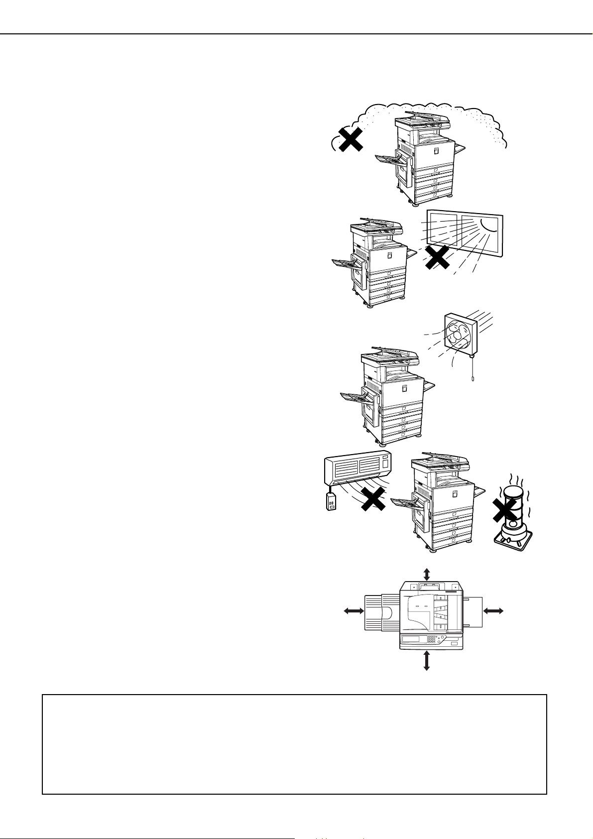
3. Do not install your machine in areas that are:
● damp, humid, or very dusty
● exposed to direct sunlight
● poorly ventilated
● subject to extreme temperature or humidity
changes, e.g., near an air conditioner or heater.
4. Be sure to allow the required space around the
machine for servicing and proper ventilation.
31-1/2"
(80cm)
11-13/16"
(30cm)
23-5/8"
(60cm)
23-5/8"
(60cm)
A small amount of ozone is produced within the copier during operation. The emission level is insufficient to cause
any health hazard.
NOTE:
3
The present recommended long term exposure limit for ozone is 0.1 ppm (0.2 mg/m
weighted average concentration.
However, since the small amount that is emitted may have an objectionable odor, it is advisable to place the copier
in a ventilated area.
) calculated as an 8 hr. time-
0-2
INSTALLATION REQUIREMENTS
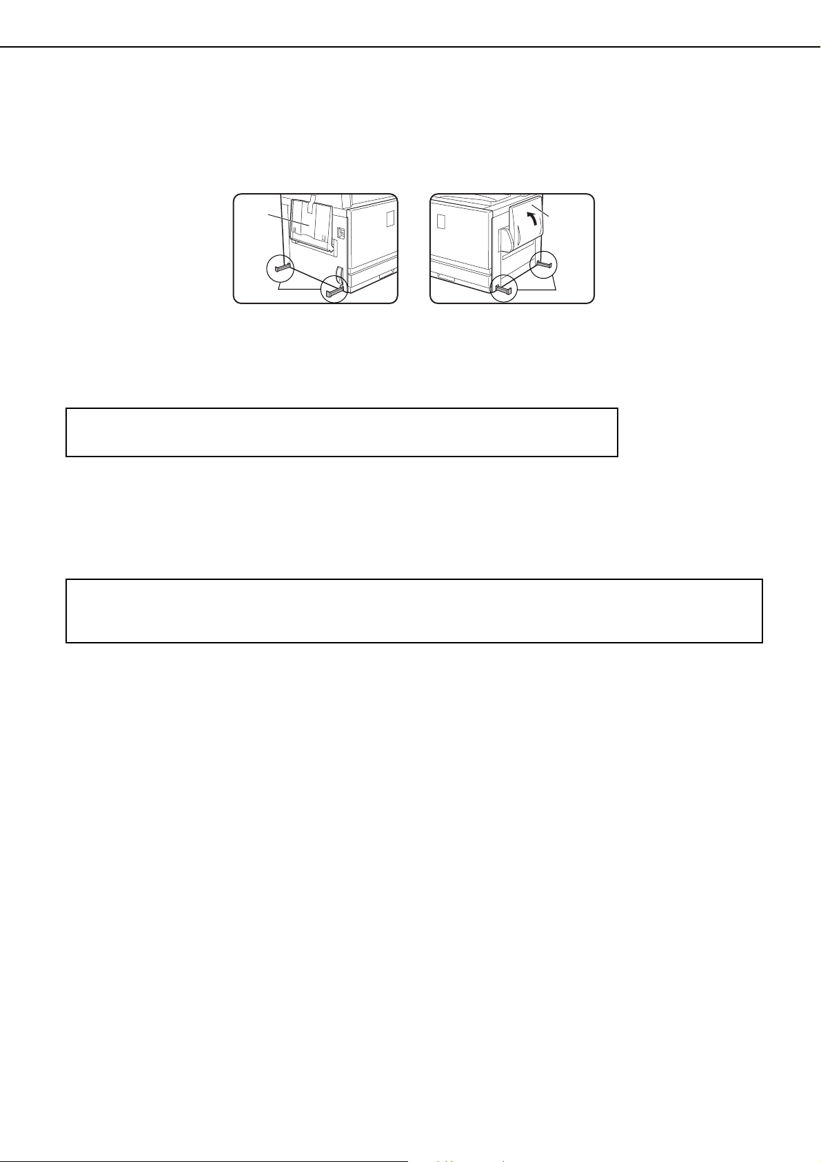
Moving this machine
Pull out the four handles as shown below, grasp them firmly, and keep the machine horizontal while moving it.
Left side Right side
Exit
tray
Handles
Before lifting the machine,
fold up the exit tray and
tape it securely to the
machine.
Caution
Two people are required to lift and carry this machine.
If the machine has been placed on a stand/paper drawer:
The stand/paper drawer is on casters for moving. Unlock the casters and the adjusters of the stand/paper drawer and
gently move the machine taking care to steady it to prevent it from toppling.
For locking and unlocking the casters and the adjusters, see page 0-4.
If the machine is to be left unused for a long time
If the machine is to be left unused for a month or longer, follow the procedure on pages 2-6 and 2-7 to release
the pressure on the fusing roller.
Before lifting the machine,
fold up the bypass tray
and tape it securely to the
machine.
Bypass
tray
Handles
0-3
CAUTIONS
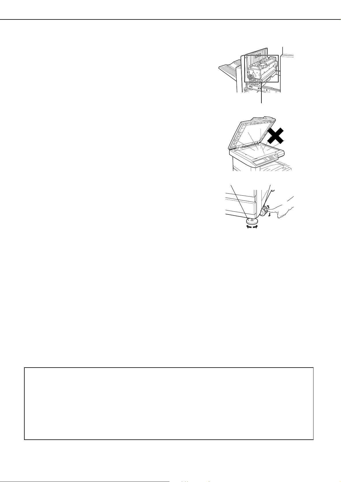
1. Do not touch the photoconductive drum. Scratches
or smudges on the drum will cause dirty prints.
2. The fusing unit is extremely hot. Exercise care in
this area.
3. Do not look directly at the light source. Doing so may
damage your eyes.
4. Four adjusters are provided on all optional stand/
paper drawer units. These adjusters should be
lowered until they contact the floor.
When moving the machine with the optional stand/
paper drawer, be sure to raise the adjusters. Also,
unlock the two casters at the front of the optional
stand/paper drawer. After moving the machine,
lower the four adjusters until they reach the floor and
lock the two casters.
Fusing unit
5. Do not make any modifications to this machine.
Doing so may result in personal injury or damage to
the machine.
6. Since this machine is heavy, it is recommended that
it be moved by more than one person to prevent
injury.
7. When connecting this machine to a computer, be
sure to first turn both the computer and the machine
off.
8. Do not make copies of anything which is prohibited
from copying by law. The following items are
normally prohibited from printing by national law.
Other items may be prohibited by local law.
●
Money ● Stamps ● Bonds ● Stocks
●
Bank drafts ● Checks ● Passports
●
Driver's licenses
Adjuster
Lock
Caster
Release
Lock
Release
"BATTERY DISPOSAL"
THIS PRODUCT CONTAINS A LITHIUM PRIMARY MEMORY BACK-UP BATTERY THAT MUST BE
DISPOSED OF PROPERLY. PLEASE CONTACT YOUR LOCAL SHARP DEALER OR AUTHORIZED SERVICE
REPRESENTATIVE FOR ASSISTANCE IN DISPOSING OF THIS BATTERY.
This product utilizes tin-lead solder, and a fluorescent lamp containing a small amount of mercury.
Disposal of these materials may be regulated due to environmental considerations.
For disposal or recycling information, please contact your local authorities or the Electronics Industries Alliance:
www.eia.org
0-4

CONTENTS
OPERATION MANUALS.................................................0-1
INSTALLATION REQUIREMENTS.................................0-2
● Moving this machine..................................................0-3
CAUTIONS......................................................................0-4
CHAPTER 1
BEFORE USING THE PRODUCT
INTRODUCTION.............................................................1-2
MAIN FEATURES ...........................................................1-2
PART NAMES AND FUNCTIONS ..................................1-4
● Exterior......................................................................1-4
● Interior .......................................................................1-5
● Part names and functions of peripheral devices........1-6
● Operation panel.........................................................1-8
● Touch panel...............................................................1-9
AUDITING MODE .........................................................1-11
● Using the machine when the auditing mode is
enabled ...................................................................1-11
CHAPTER 2
MANAGING THE MACHINE
CHAPTER 3
PERIPHERAL DEVICES
SADDLE STITCH FINISHER ......................................... 3-2
● Part names and functions ......................................... 3-2
● Specifications............................................................ 3-2
● Saddle stitch finisher functions ................................. 3-4
● Using the saddle stitch finisher................................. 3-6
● Staple cartridge replacement and staple jam removal
.................................................................................. 3-7
● Misfeed in the saddle stitch finisher........................ 3-10
● Troubleshooting saddle stitch finisher problems..... 3-12
● Stapling position quick reference guide for duplex
output...................................................................... 3-13
● Relation between print image and saddle stitch ..... 3-14
LARGE CAPACITY TRAY............................................ 3-15
● Part name ............................................................... 3-15
● Specifications.......................................................... 3-15
● Loading paper in the large capacity tray................. 3-16
● Misfeed in the large capacity tray ........................... 3-17
LOADING PAPER...........................................................2-2
● Loading paper in paper tray 1....................................2-2
● Changing the paper size in paper tray 1....................2-2
● Loading paper in the bypass tray ..............................2-4
●
Loading paper in the stand/1 x 500 sheet paper drawer/
stand/3 x 500 sheet paper drawer
● Specifications (stand/1 x 500 sheet paper drawer/
stand/3 x 500 sheet paper drawer)............................2-7
● Loading paper in the duplex module/2 x 500 sheet
paper drawer .............................................................2-8
● Specifications (duplex module/2 x 500 sheet paper
drawer) ......................................................................2-8
● Specifications of paper trays .....................................2-9
● Setting the paper type (except the bypass tray)......2-11
● Setting the paper size when an extra size is loaded
.................................................................................2-11
● Setting the paper type and paper size in the bypass
tray...........................................................................2-12
CUSTOM SETTINGS....................................................2-13
● Operation procedure common to all custom settings
.................................................................................2-13
● About the settings....................................................2-14
REPLACING THE TONER CARTRIDGES ...................2-15
STORAGE OF SUPPLIES ............................................2-17
MISFEED REMOVAL....................................................2-18
● Misfeed removal guidance.......................................2-18
● Misfeed in the paper feed area................................2-19
● Misfeed in the transport area, fusing area, and exit
area .........................................................................2-20
● Misfeed in the stand/1 x 500 sheet paper drawer....2-21
● Misfeed in the stand/3 x 500 sheet paper drawer....2-21
● Misfeed in the duplex bypass/inverter unit and duplex
module/2 x 500 sheet paper drawer........................2-22
TROUBLESHOOTING..................................................2-24
................................2-7
0-5

CONTENTS
CHAPTER 4
BEFORE MAKING COPIES
PART NAMES AND FUNCTIONS (The Reversing Single
Pass Feeder).................................................................. 4-2
● Exterior ..................................................................... 4-2
● Operation Panel........................................................ 4-3
● Touch Panel (main screen of copy mode) ................ 4-4
REVERSING SINGLE PASS FEEDER.......................... 4-5
● Acceptable originals.................................................. 4-5
SETTING ORIGINALS ................................................... 4-6
SELECTING THE ORIGINAL SIZE................................ 4-8
STORING, DELETING, AND USING ORIGINAL SIZES
.... 4-9
CHAPTER 5
BASIC PROCEDURE FOR MAKING
COPIES
NORMAL COPYING....................................................... 5-2
● Copying from the reversing single pass feeder ........ 5-2
● Automatic two-sided copying from the reversing single
pass feeder............................................................... 5-6
● Copying from the document glass ............................ 5-7
● Automatic two-sided copying from the document glass
.................................................................................. 5-9
EXPOSURE ADJUSTMENTS...................................... 5-10
REDUCTION/ENLARGEMENT/ZOOM ........................ 5-12
● Automatic selection (auto image) ........................... 5-12
● Manual selection..................................................... 5-13
● XY ZOOM ............................................................... 5-15
SPECIAL PAPERS....................................................... 5-17
CHAPTER 6
IMAGE EDIT MENU ..................................................... 6-16
● Single color .............................................................6-17
● Mirror image ............................................................ 6-17
● Photo Repeat ..........................................................6-18
● Multi shot................................................................. 6-19
● 11" x 17" (A3) Full-bleed ......................................... 6-21
● Multi-page enlargement .......................................... 6-22
● Pamphlet copy ........................................................ 6-24
JOB PROGRAM MEMORY.......................................... 6-25
● Storing a job program.............................................. 6-25
● Recalling a job program .......................................... 6-26
● Deleting a stored job program................................. 6-26
INTERRUPTING A COPY RUN ................................... 6-27
CHAPTER 7
MACHINE MAINTENANCE (FOR
COPYING)
REMOVING AN ORIGINAL MISFEED........................... 7-2
● Removing a misfed original from the reversing single
pass feeder ............................................................... 7-2
USER MAINTENANCE (For copying) ............................ 7-3
CLEANING THE ORIGINAL SCANNING AREA ............7-3
TROUBLESHOOTING.................................................... 7-4
CHAPTER 8
SPECIFICATIONS
SPECIFICATIONS.......................................................... 8-2
● Copier and Main unit................................................. 8-2
● Reversing single pass feeder....................................8-4
● Duplex bypass/inverter unit (optional)....................... 8-4
INDEX............................................................................. 8-5
CONVENIENT COPY FUNCTIONS
SPECIAL MODES .......................................................... 6-2
● Common operation procedure for using the special
functions ................................................................... 6-3
● Margin shift ............................................................... 6-4
● Erase ........................................................................ 6-5
● Dual page copy......................................................... 6-6
● Centering .................................................................. 6-7
● Transparency film with insert sheets ........................ 6-8
● Covers ...................................................................... 6-9
● B/W reverse ............................................................ 6-10
COLOR ADJUSTMENTS MENU.................................. 6-11
● RGB adjust ............................................................. 6-12
● Sharpness............................................................... 6-13
● Suppress background............................................. 6-13
● Color balance.......................................................... 6-14
● Brightness............................................................... 6-15
● Intensity .................................................................. 6-15
0-6

CHAPTER 1
BEFORE USING THE
PRODUCT
This chapter contains basic information that should be read before using
the product.
Page
INTRODUCTION ...........................................................................................1-2
MAIN FEATURES..........................................................................................1-2
PART NAMES AND FUNCTIONS .................................................................1-4
●
Exterior...................................................................................................1-4
●
Interior....................................................................................................1-5
●
Part names and functions of peripheral devices ....................................1-6
●
Operation panel......................................................................................1-8
●
Touch panel ...........................................................................................1-9
AUDITING MODE ........................................................................................1-11
●
Using the machine when the auditing mode is enabled.......................1-11
1-1
INTRODUCTION
To gain the maximum benefits in using this product, it is recommended that the user read this manual to become
familiar with all the features and functions of the basic product and the precautionary information contained in the
manual.
This product is a high speed Digital full color copier/printer that can be expanded to become multifunctional through
the installation of optional peripheral devices. The product can be extended to include printer, network scanning or
network printing capabilities. This manual describes the basic use of the product as a copier and does not contain
information on using any of the optional peripheral devices. Separate operation manuals are included with each of
the optional peripheral devices. Refer to these manuals for their operation.
Original and paper sizes
This machine allows use of standard sizes in both the inch and AB systems.
These are shown in the tables below.
Sizes in the inch system
11" x 17" (LEDGER)
8-1/2" x 14" (LEGAL)
8-1/2" x 13" (FOOLSCAP)
8-1/2" x 11" (LETTER)
7-1/4" x 10-1/2" (EXECUTIVE)
5-1/2" x 8-1/2" (INVOICE)
Sizes in the AB system
A3
B4
A4
B5
A5
The meaning of "R" in original and paper size indications
Some original and paper sizes can be placed in either the portrait or landscape orientations. To differentiate between
landscape and portrait, the landscape orientation size indication will contain an "R". These are indicated as 8-1/2" x
11"R, 5-1/2" x 8-1/2"R, A4R, B5R, etc. Sizes that can be placed only in the landscape orientation (11" x 17", 8-1/2"
x 14", 8-1/2" x 13", A3, B4) do not contain the "R" in their size indication.
Size indication with "R"
Landscape orientation
Size indication without "R"
Portrait orientation
MAIN FEATURES
Full-color copies with vivid colors based on digital technology
1
Photos, color text, and other originals are scanned by full-color CCD sensors, and the acquired image
information is output in vivid full color at a resolution of 600 dpi using digital image processing technology.
The machine can also be used as a full color network printer and network scanner.
A range of optional units to enhance productivity
2
A range of optional equipment is available to enhance productivity, such as duplex units for producing two-sided
output, additional paper feed units to increase the number of available paper sizes and paper capacity, and
paper output units that are capable of stapling and saddle stitch binding.
1-2
MAIN FEATURES
Advanced image processing features based on digital technology
3
The scanned image data is converted to digital data, enabling the following advanced image processing features:
●●●● Photo Repeat :
Up to 24 full-size copies of a photo image can be made on a single sheet of paper (page 6-18).
●●●● Multi shot :
Up to four original pages can be copied onto a single sheet (page 6-19).
●●●● Pamphlet copy* :
Copies of original pages are arranged in proper order for copying so that the copies can be center-stapled and
folded into a pamphlet (page 6-24).
* Pamphlet copy requires the Duplex module/2 x 500 sheet paper drawer and Duplex bypass/inverter unit
options. If a saddle stitch finisher is installed, copies can be stapled in two positions along the center of copies
and folded at the center.
Image processing manual exposure adjustment for optimal copying
4
Image processing is optimized for the type of original being copied (text, photo, mixed text and photo or map). This
along with the ability to manually adjust exposure makes it possible to obtain copies that are faithful to the original.
Standard offset function makes it easy to distinguish between sets of copies
5
As sets of copies are delivered to the center tray, each set is offset from the previous set for easy separation.
1
PostScript compatible
6
Installation of an optional PS expansion kit (AR-PK4) gives PostScript compatibility (PostScript 3).
®
As an ENERGY STAR
®
ENERGY STAR
guidelines for energy efficiency.
Partner, SHARP has determined that this product meets the
Energy saving features
This product has the following two power reducing modes to help conserve natural resources and reduce
environmental pollution.
Preheat mode
Preheat mode automatically reduces the temperature of the fusing unit after the time set in the key operator
programs elapses when the machine is on standby. This allows the machine to use less power while on
standby. The machine automatically returns to normal operation when a key is pressed on the operation
panel, or when an original is placed to make a copy or send a fax.
Auto power shut-off mode
Auto power shut-off mode automatically shuts off power to the fusing unit after the time set in the key
operator programs elapses when the machine is on standby. This minimizes the power used by the
machine while on standby. When this mode activates, the touch panel screen turns off.
To return the machine to normal operation, press the mode select key (the indicator of this key will be lit).
Auto power shut-off mode can be configured in the key operator programs. The mode is initially set (factory
default setting) to activate after 60 seconds elapses. (See page 9 of the key operator's guide.)
If a print job or fax is received while auto power shut-off mode or preheat mode is activated, the machine
automatically returns to normal operation.
The Environmental Choice Program guidelines are applied to the products only in Canada. The
products that meet the Environmental Choice Program guidelines carry the logo shown above.
The products without the logo may not meet the Environmental Choice Program guidelines.
1-3
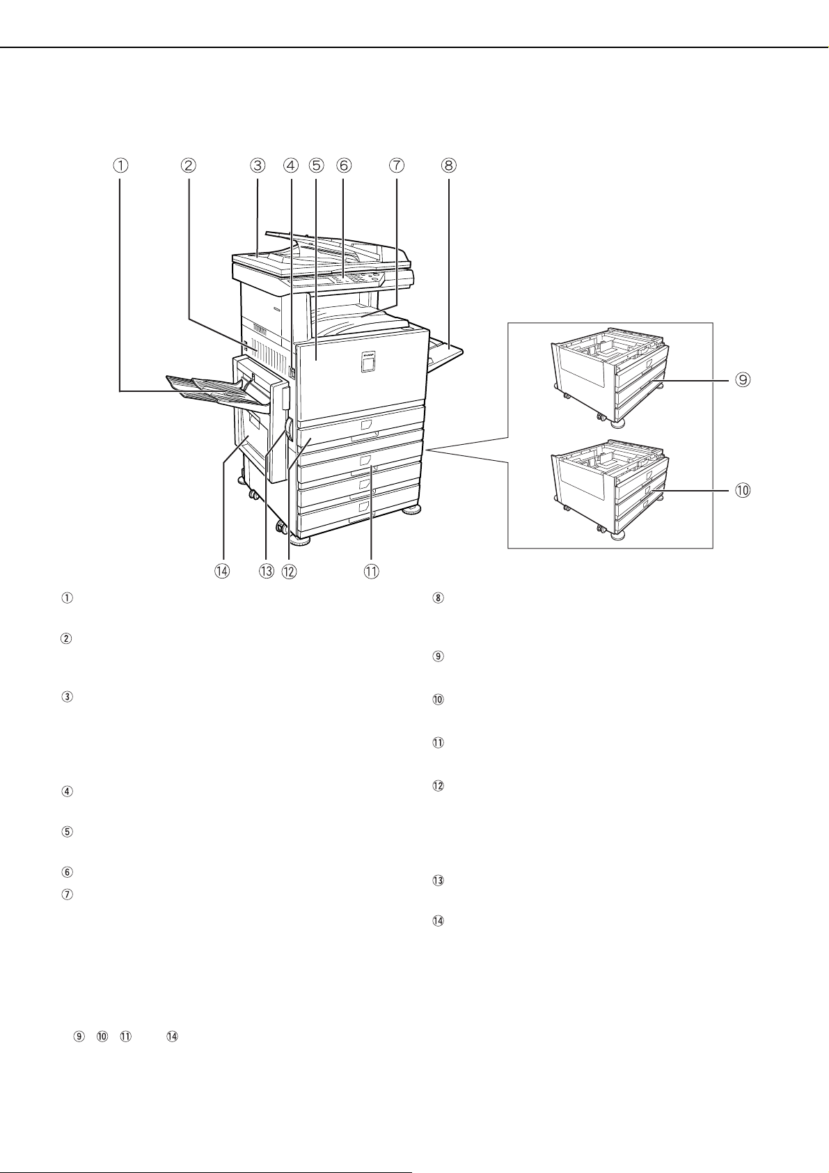
PART NAMES AND FUNCTIONS
Exterior
Left tray (See page 5-5)
Finished sheets are deposited here.
Left side cover
Open this cover when a paper misfeed occurs in
the fusing unit or the transfer unit.
Reversing single pass feeder
This automatically feeds originals to be scanned.
The feeder can turn the original over and scan the
back side as well as the front side for support of
two-sided originals.
Power switch
Press to turn power on and off.
Front cover
Open to replace toner cartridge.
Operation panel
Center tray (See page 5-5)
Finished sheets are deposited here.
Bypass tray
Special papers (including transparency film) and
copy paper can be fed from the bypass tray.
Stand/1 x 500 sheet paper drawer *
(See page 2-7)
Stand/3 x 500 sheet paper drawer *
(See page 2-7)
Duplex module/2 x 500 sheet paper drawer*
(See page 2-8)
Paper tray
Each tray can hold approximately 500 sheets of the
recommended paper for color (21 lbs. or 80 g/m
or approximately 500 sheets of SHARP standard
paper (21 lbs. or 80 g/m
Left side cover release
Push this release up to open the left side cover.
Duplex bypass/inverter unit and exit tray* (See
page 1-6)
2
).
2
),
* , , and are peripheral devices. For a description of these devices, see page 1-6.
1-4
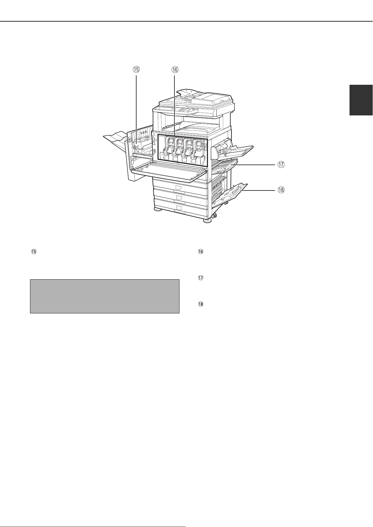
Interior
PART NAMES AND FUNCTIONS
1
Fusing unit
Toner images are fused here.
CAUTION
The fusing unit is hot. Take care in removing misfed
paper.
Toner cartridge
The toner cartridge must be replaced when
indicated on the operation panel. (See page 2-15)
Right side cover
Open when a misfeed has occurred in the paper
feed area.
Right cover of paper drawer
Open this cover to remove paper misfed in the
paper drawer.
1-5
PART NAMES AND FUNCTIONS
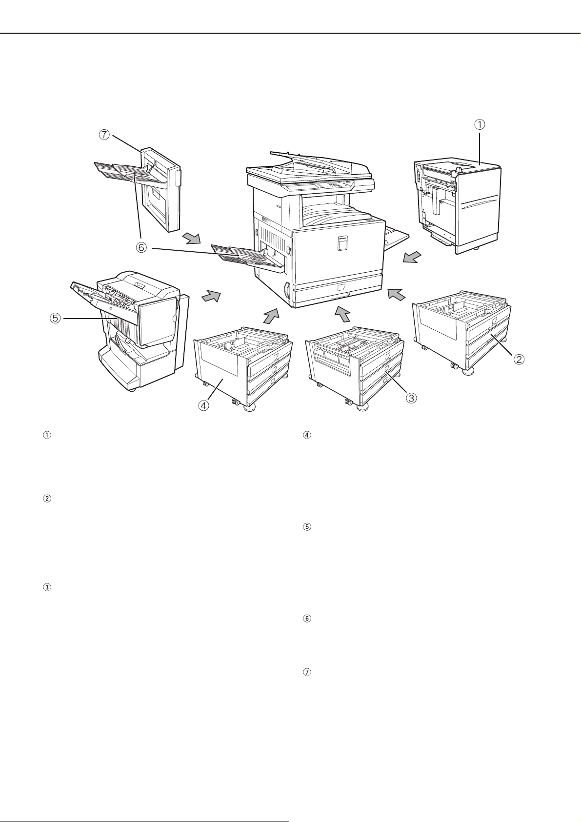
Part names and functions of peripheral devices
Large Capacity tray (AR-LC8)
The large capacity tray provides the added
convenience of having 3,500 sheets of 8-1/2" x 11"
or A4 paper (21 lbs. or 80 g/m
2
) available.
Stand/1 x 500 sheet paper drawer (AR-D17N)
This stand has one paper tray. It can hold
approximately 500 sheets of the recommended
paper for color (21 lbs. or 80 g/m
2
), or
approximately 500 sheets of SHARP standard
2
paper (21 lbs. or 80 g/m
).
Duplex module/2 x 500 sheet paper drawer (AR-D19N)
This stand includes a module for automatic
two-sided printing and two paper trays. The two
trays can hold approximately 500 sheets of the
recommended paper for color (21 lbs. or 80 g/m
2
or approximately 500 sheets of SHARP standard
2
paper (21 lbs. or 80 g/m
). To perform two-sided
printing, a duplex bypass/inverter unit (AR-RB1) is
required.
Stand/3 x 500 sheet paper drawer (AR-D18N)
This stand has three paper trays. Each tray can
hold approximately 500 sheets of the
2
recommended paper for color (21 lbs. or 80 g/m
),
or approximately 500 sheets of SHARP standard
2
paper (21 lbs. or 80 g/m
).
Saddle stitch finisher (AR-F13)
The finisher can deliver sets saddle stitched and
folded at the paper centerline to form a pamphlet,
edge stapled in three different modes or unstapled.
For two-hole or three-hole output, a hole punch
module must be installed.
Exit tray (AR-TE3)
),
The exit tray is installed on the output outlet of the
machine or the duplex tray / inverter unit.
Duplex bypass/inverter unit (AR-RB1)
This module is required to automatically turn paper
over within the machine for automatic two-sided
printing.
1-6

■■■■ Other optional equipment
PART NAMES AND FUNCTIONS
●●●●PS3 expansion kit (AR-PK4)
This kit provides compatibility of PostScript level 3
to the printer.
●●●●Facsimile expansion kit (AR-FX10)
This kit must be installed to use the fax function.
●●●●Fax memory (8 MB) (AR-MM9)
This adds memory for use by the fax function.
●●●●256 MB optional memory (AR-SM5)
This adds memory that is used for the copy
function, printer function, and scanner function.
■■■■ Face-up and face-down output
After printing, the paper is delivered to the exit tray. This product has two exit trays (center tray and left tray). The
paper specifications (page 8-3) and output conditions differ for each tray; however, if the paper and output
conditions are such that the paper can be delivered to either tray, you can select the tray to which the paper will
go.
● Paper exits to the center tray face-down only.
● Paper exits to the left tray face-up only. However, if a duplex bypass/inverter unit has been installed,
face-down output is also possible. In this case, face-up or face-down output is automatically selected
according to the paper and output conditions (it is not possible to manually select face-up or face-down.)
1
1-7
PART NAMES AND FUNCTIONS
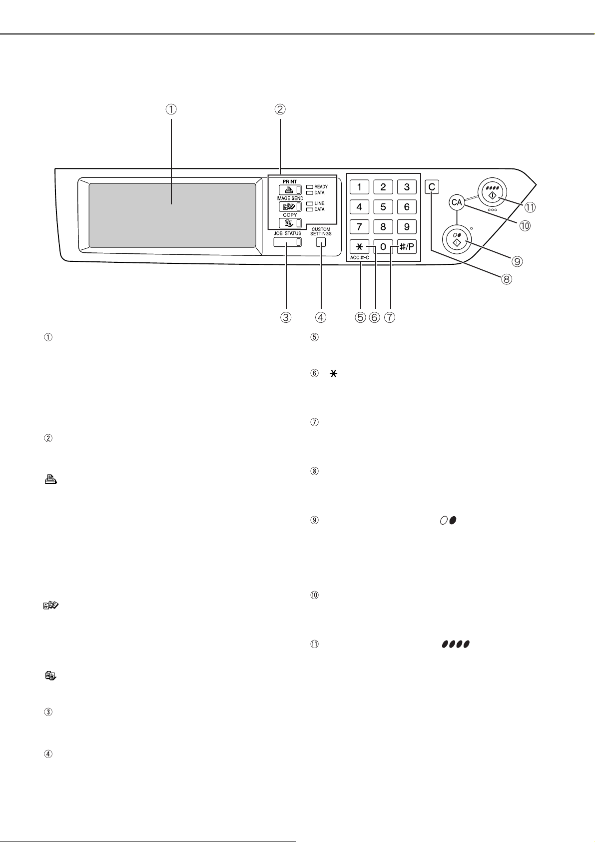
Operation panel
Touch panel
The machine status, messages and touch keys are
displayed on the panel. When using the touch
panel, first change the display to the mode that you
wish to use: printer mode, copy mode, network
scanner mode, or fax mode*. For details see the
next page.
Mode select keys and indicators
Use to change modes and the corresponding
display on the touch panel.
[PRINT] key/READY indicator/DATA indicator
Press to enter the printer mode.
READY indicator
Print data can be received when this indicator is
lit.
DATA indicator
Lights up or blinks when print data is being
received. Also lights up or blinks when printing is
being performed.
[IMAGE SEND] key/LINE indicator/DATA
indicator
Press this key to switch the display between
network scanner mode and fax mode*. (See the
operation manuals for network scanner and fax.)
[COPY] key
Press to select the copy mode.
Numeric keys
Use to enter number values for various settings.
[ ] key ([ACC.#-C] key)
This is used when the copy, network scan, and fax*
functions are used.
[#/P] key
This is used as a program key when using the copy
function, and to dial when using the fax function*.
[C] key
This key is
mode, and fax mode*.
[BLACK COPY START ( )] key
This is used to make black and white copies and to
scan a black and white original when the network
scan function is used. This is also used to scan an
original to be faxed using the fax function*.
[CA] key
This key is
mode, and fax mode*.
[COLOR COPY START ( )] key
This is used to make full-color or single-color
copies and to scan a color original when the
network scanner function is used.
used in copy mode, network scanner
used in copy mode, network scanner
[JOB STATUS] key
Press to display the current job status. (See page
1-10.)
[CUSTOM SETTINGS] key
Use to adjust the contrast of the touch panel or to
set key operator programs. (See page 2-13.)
1-8
* When the fax option is installed.
Touch panel
JOB QUEUE
COPY
Suzuki
0666211221
003 / 00
003 / 00
010 / 00
SETS / PRO
1/13
COMPLETE
CANCEL OK
RIGHT
BINDING
LEFT
BINDING
TRANSPARENCY
INSERTS
DUAL PAGE
COPY
SPECIAL MODES
2-SIDED COPY
OUTPUT
READY TO COPY.
B4
P
OR
A3
A4
DUPLEX
PART NAMES AND FUNCTIONS
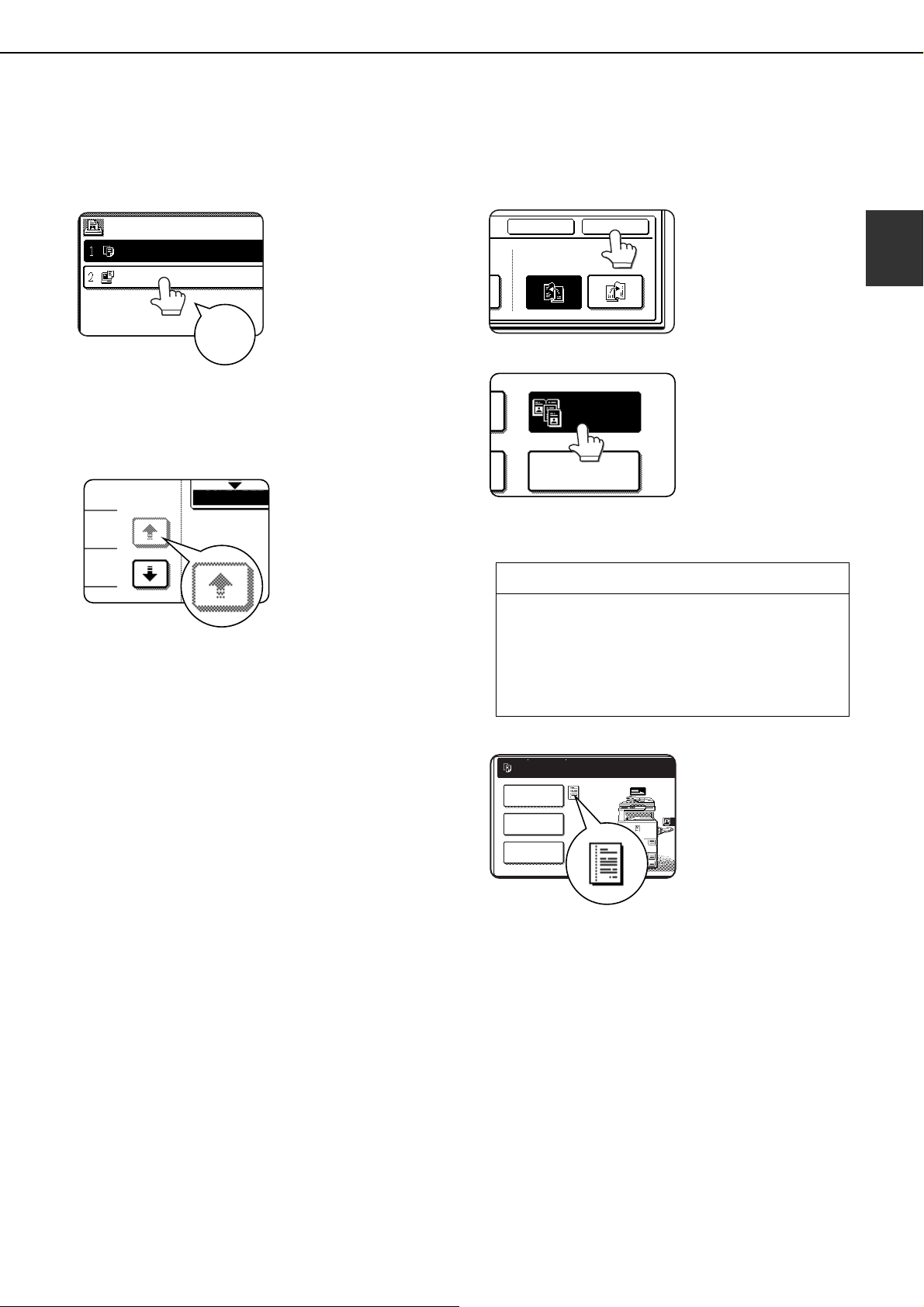
Using the touch panel
[Example 1]
Items on the touch panel
are easily selectable by
touching the key
associated with the item
with a finger. Selection
of an item will be
Beep
tone
[Example 2]
The confirmation beeps can be disabled by a key
operator program. (See page 10 of the key
operator's guide.)
accompanied with a
beep tone to confirm the
item was selected. Also,
the key area for the item
will be highlighted for
visual confirmation.
Keys which are grayed
out on any screen are
not selectable. If a
grayed out key is
touched, a double beep
will be sounded.
Selection of function
[Example 1]
[Example 2]
Copier feature
● Dual page copy
● Centering
● Transparency inserts
● Mirror image
● 11"x17" (A3) Full-bleed
● B/W Reverse
Items which are
highlighted at the time a
screen appears are
already selected and will
be registered to function if
the [OK] key is touched.
When the machine is
used in the copy mode,
the functions shown in
the table below can only
be set or canceled on
the special feature
screen by alternate
touches of the function
keys on the panel.
1
The touch panel screens shown in this manual are
printed images, and may appear different from the
actual screens.
[Example 3]
When the machine is
used in the copy mode
and a special feature is
selected, a
corresponding icon
representing the feature
will appear on the touch
key and on the main
screen of the mode
selected. If this icon is
touched, the setting
screen of the function (or
a menu screen) will
appear, allowing the
settings to be checked
or adjusted and the
function to be canceled
easily.
1-9
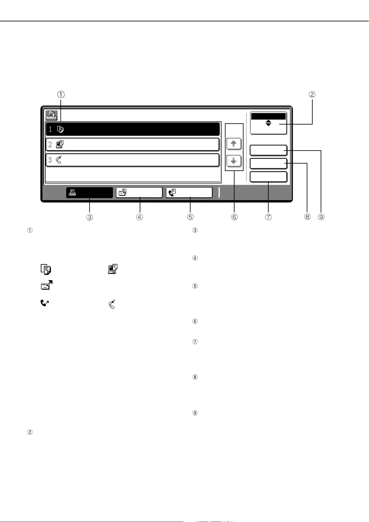
PART NAMES AND FUNCTIONS
Job status screen (common to print, copy, network scan and fax)
This screen is displayed when the [JOB STATUS] key on the operation panel is pressed.
A job list showing the current job at the top of the job queue or a list showing completed jobs can be displayed.
The contents of jobs can be viewed or jobs can be deleted from the queue. (The screen below is an example and
differs from actual screens.)
JOB QUEUE
COPY
Suzuki
066211221
PRINT JOB SCANNER JOB
Job list
This shows the current job and the jobs waiting to
be run. The icons to the left of the jobs in the queue
show the job mode.
Copy mode Printer mode
Network scanner mode
Fax send job Fax reception job
SETS / PROGRESS
003 / 000
003 / 000
001 / 000
STATUS
PAPER EMPTY
WAITING
WAITING
FAX JOB
[PRINT JOB] key
Use to display the print job list for printer, copy and
fax mode.
[SCANNER JOB] key
This displays a list of jobs that only used the
network scanner function.
[FAX JOB] key
This displays the transmission/reception status
and finished jobs of fax mode when the fax option
is installed.
JOB QUEUE
1/1
*
COMPLETE
DETAIL
PRIORITY
STOP/DELETE
The displayed jobs in the job list are themselves
operation keys. To cancel printing or to give a job
the highest print priority, touch the relevant job key
to select the job and execute the desired operation
using the keys described in 5 and 6.
* "PAPER EMPTY" in the job status display
When a job status display indicates "PAPER
EMPTY", the specified paper size for the job is not
loaded in any of the trays.
When the [DETAIL] key appears, the key of a job in
the job queue can be touched followed by the
[DETAIL] key to change the paper size selection to
a different paper size (only in printer mode).
Mode select key
This only appears in the job status screen of fax
mode. The key is used to switch the job list display
between "JOB QUEUE" and "COMPLETE".
"JOB QUEUE": Shows stored jobs and the job in
progress.
"COMPLETE" : Shows finished jobs.
Display switching keys
Use to switch the page of the displayed job list.
[STOP/DELETE] key
Use to cancel or delete the current job or delete the
selected reserved job. Note that a fax print job
cannot be canceled or deleted.
[PRIORITY] key
This only appears in the job status screen of fax
mode. Touch this key to give priority to a job that
has been selected in the job queue.
[DETAIL] key
The key is only effective for computer print jobs and
only appears in the job status screen of the printer
mode. It is used to display detailed information of a
selected print job and to change the paper size for
the print job.
1-10
AUDITING MODE
ENTER YOUR ACCOUNT NUMBER.
ENTER YOUR ACCOUNT NUMBER FOR THE COLOR MODE.
PRESS [CANCEL] TO CHANGE TO B/W MODE.
CANCEL
When the account counter function is turned on, a count is kept of the number of copy sheets used by each account
(maximum of 200 accounts). The counts can be displayed and totaled as needed.
The key operator programs can be used to enable auditing mode separately for copy mode, fax mode, network
scanner mode, and printer mode. (Page 6 of key operator's guide)
Using the machine when the auditing mode is enabled
The procedure for using the machine for copying functions when the Auditing Mode has been enabled for the copier
functions is explained below.
NOTES
● When the account counter is turned on for fax or network scanner functions, a message will appear prompting
you to enter your account number each time the touch panel is changed to the main screen of the function. Enter
your account number as explained below and then proceed with the job.
● When the account counter is turned on for the printer function, you must enter your account number in the setting
screen of the printer driver on your computer in order to print.
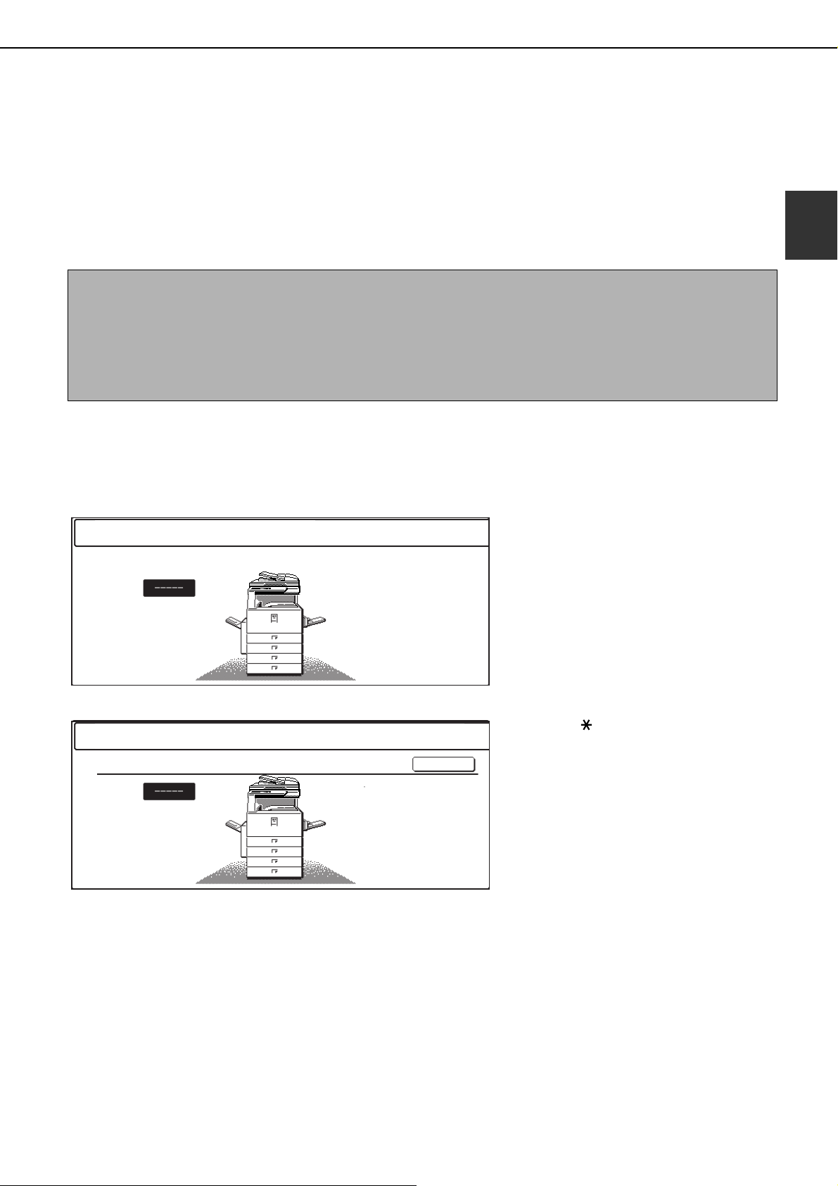
When the account counter is turned on, the following messages appear on the touch panel. There are two types of
prompts, depending on whether the account counter was turned on for both the color copy and the black and white
copy modes, or only for color copy mode.
●Account counter enabled for both the color copy and the black and white copy modes
1
●The account counter is enabled only for the color copy mode
AUDITING MODE FOR COLOR
In this case, enter your 5-digit account number as explained on the next page to gain access to the copier functions.
When the [ ] key ([ACC.#-C] key) or the
[COLOR COPY START] key is pressed, the
message at left appears.
1-11
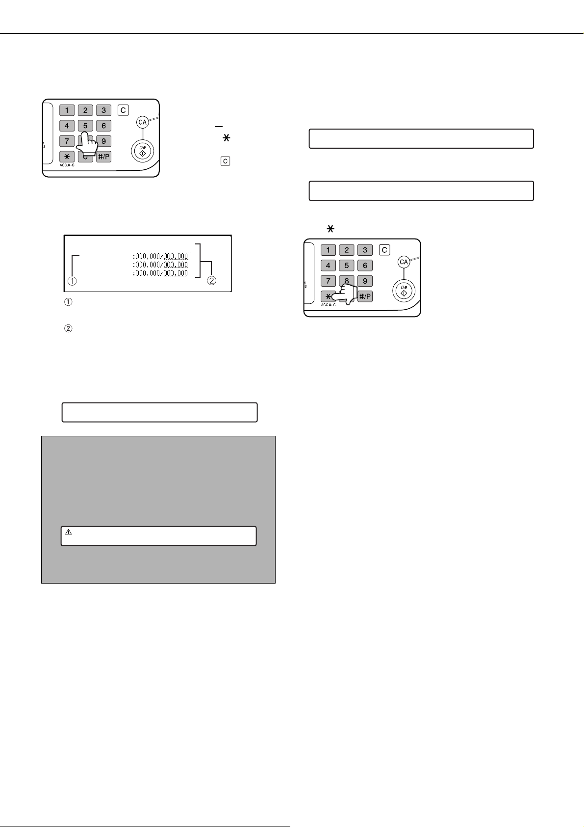
AUDITING MODE
Enter your account number (5 digits) with
1
the numeric keys.
As you enter your
account number, the
hyphens ( ) change to
asterisks ( ). If you
enter an incorrect digit,
press the key and
re-enter the correct digit.
When a correct account
number is entered, the
following message will
appear.
ACCOUNT STATUS:COPIES MADE/REMAINING
B/W
S.COLOR
F.COLOR
This does not appear if the account counter
has only been set for color copy mode.
If a limit has been set by key operator program
for the number of copies that can be made by
the account, the remaining number that can be
made is displayed.
This message appears for several seconds and
then changes to the following message.
Follow the appropriate steps to perform
2
the copy job.
When copying is begun, the following message
will appear.
READY TO COPY.
PRESS [ACC.#] WHEN FINISHED.
In the case of interrupt copying (page 6-27), the
following message will appear.
READY TO COPY. WHEN INTERRUPT COPYING
IS FINISHED PRESS [CANCEL].
When the copy job is finished, press the
3
[ ] key ([ACC.#-C] key)
READY TO COPY.
NOTE
If "Account number security" is turned on in the key
operator programs, the following message will
appear in the event that an incorrect account number
is entered three times in a row. (Page 8 of the key
operator's guide)
PLEASE SEE YOUR KEY OPERATOR FOR
ASSISTANCE.
While this message appears (for about one minute),
no other operations can be performed.
1-12

CHAPTER 2
MANAGING THE MACHINE
This chapter explains how to load paper, replace the toner cartridge,
and remove paper misfeeds. It also contains information about supplies.
Page
LOADING PAPER..........................................................................................2-2
●
Loading paper in paper tray 1 ................................................................2-2
●
Changing the paper size in paper tray 1 ................................................2-2
●
Loading paper in the bypass tray...........................................................2-4
●
Loading paper in the stand/1 x 500 sheet paper drawer/stand/3 x 500
sheet paper drawer..................................................................................... 2-7
●
Specifications (stand/1 x 500 sheet paper drawer/stand/3 x 500
sheet paper drawer)...............................................................................2-7
●
Loading paper in the duplex module/2 x 500 sheet paper drawer .........2-8
●
Specifications (duplex module/2 x 500 sheet paper drawer) .................2-8
●
Specifications of paper trays ..................................................................2-9
●
Setting the paper type (except the bypass tray)...................................2-11
●
Setting the paper size when an extra size is loaded ............................2-11
●
Setting the paper type and paper size in the bypass tray ....................2-12
CUSTOM SETTINGS ..................................................................................2-13
●
Operation procedure common to all custom settings...........................2-13
●
About the settings ................................................................................2-14
REPLACING THE TONER CARTRIDGES..................................................2-15
STORAGE OF SUPPLIES...........................................................................2-17
MISFEED REMOVAL ..................................................................................2-18
●
Misfeed removal guidance ...................................................................2-18
●
Misfeed in the paper feed area ............................................................2-19
●
Misfeed in the transport area, fusing area, and exit area.....................2-20
●
Misfeed in the stand/1 x 500 sheet paper drawer................................2-21
●
Misfeed in the stand/3 x 500 sheet paper drawer................................2-21
●
Misfeed in the duplex bypass/inverter unit and duplex module/2 x 500
sheet paper drawer ..............................................................................2-22
TROUBLESHOOTING.................................................................................2-24
2-1
LOADING PAPER
The message "ADD PAPER" or "OPEN TRAY AND ADD PAPER" will appear when paper runs out during operation.
Follow the procedure below to load paper.
NOTES
● Do not use curled or folded paper. Doing so may cause a misfeed.
● For best results use paper supplied by SHARP. (See pages 2-9, 2-17.)
● When you change the paper type and size in paper tray 1, you must change the paper type and size settings as
explained in "Setting the paper type" (page 2-11).
● Do not place heavy objects or press hard on any tray which is pulled out.
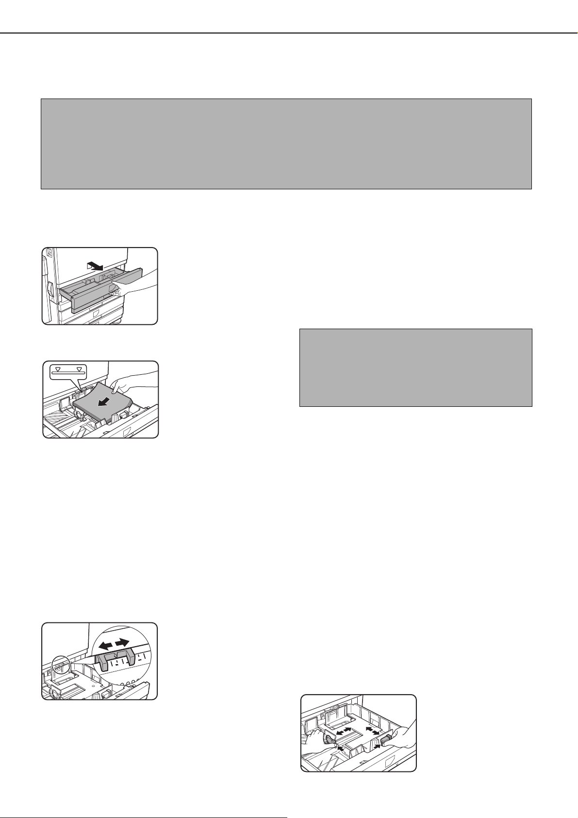
Loading paper in paper tray 1
Pull out paper tray 1.
1
Load paper into the tray.
2
Gently pull the tray out
until it stops.
Load a stack of paper no
higher than the indicator
line (about 500 sheets of
the recommended paper for
color (21 lbs. or 80
approximately 500 sheets
of SHARP standard paper
(21 lbs. or 80
g/
m2)).
g/
m2), or
Gently push tray 1 into the machine.
3
Push the tray firmly all the way into the machine.
Set the paper type.
4
If you change the paper type, be sure to set the
paper type refer to "Setting the paper type" (page
2-11).
NOTE
If you load a different size of the same type of paper,
you only need to change the position of the size slide
(see step 2 below); you do not need to change the
paper type.
Loading paper in paper tray 1 is now
5
complete.
Changing the paper size in paper tray 1
The following paper size settings are available for paper tray 1: 11" x 17" to 8-1/2" x 5-1/2" (A3 to A5), and "EXTRA"*1.
Use the following procedure to change the size as needed.
1
This is limited to square or rectangular paper, 11" x 17" to 8-1/2" x 5-1/2" (A3 to A5) size.
*
Pull out paper tray 1.
1
If paper remains in the tray, remove it.
Adjust the paper size slide to the paper
2
size.
Move the paper size
slide right or left to
indicate the paper size
being loaded.
If a special size paper is
loaded in the paper tray,
set the size slide to
"EXTRA" to inform the machine that a special size
paper has been loaded. (When AB-based size
paper is loaded, move the size slide to "EXTRA".)
2-2
Note that setting the size slide to "EXTRA" only
informs the machine that a special size of paper
has been loaded; it does not inform the machine of
the specific size. If you wish to inform the machine
of the specific size, follow the steps in "Setting the
paper size when an extra size is loaded" (page 2-
11). (If you do not set a size, part or all of the image
may not print.)
Adjust the guide plates A and B by
3
squeezing their lock levers and sliding
them to the paper size to be loaded.
The guide plates A and
B are slidable. Adjust
them to the paper size to
be loaded while
squeezing their lock
levers.
LOADING PAPER
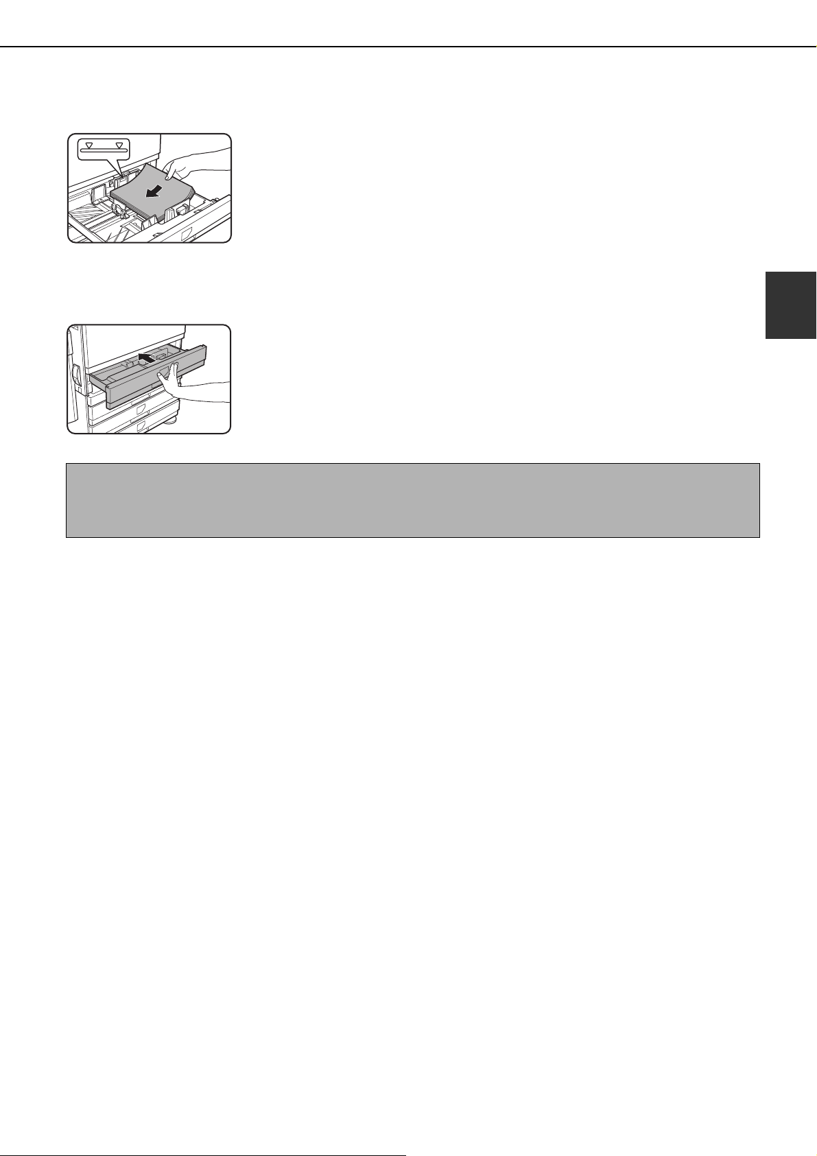
Load paper into the tray.
4
Gently push tray 1 into the machine.
5
Push the tray firmly all
the way into the
machine.
NOTE
If the size slide position (step 2 of page 2-2) is not set correctly after changing the paper size, or if the paper type
(page 2-11) is not set correctly, incorrect paper selection or paper misfeeding may occur.
Set the paper type of the paper that was
6
loaded in the 1st tray.
If you loaded a different type of paper from the
previous paper, be sure to set the new paper type
as explained in "Setting the paper type" (page 2-
11).
Changing paper size in paper tray 1 is now
7
complete.
2
2-3
LOADING PAPER
Loading paper in the bypass tray
The bypass tray can be used to feed the same paper specified for paper tray 1 or for special papers. For paper types
that can be used in the bypass tray, see the specifications for the bypass tray in the paper tray specifications (page
2-9).
Up to 250 sheets of SHARP standard paper or up to 100 postcards can be set in the bypass tray.
NOTES
● After loading the paper in the bypass tray, be sure to set the paper type and size (step 4) if these were changed.
● Do not use inkjet paper. This may cause misfeeds in the fusing unit.
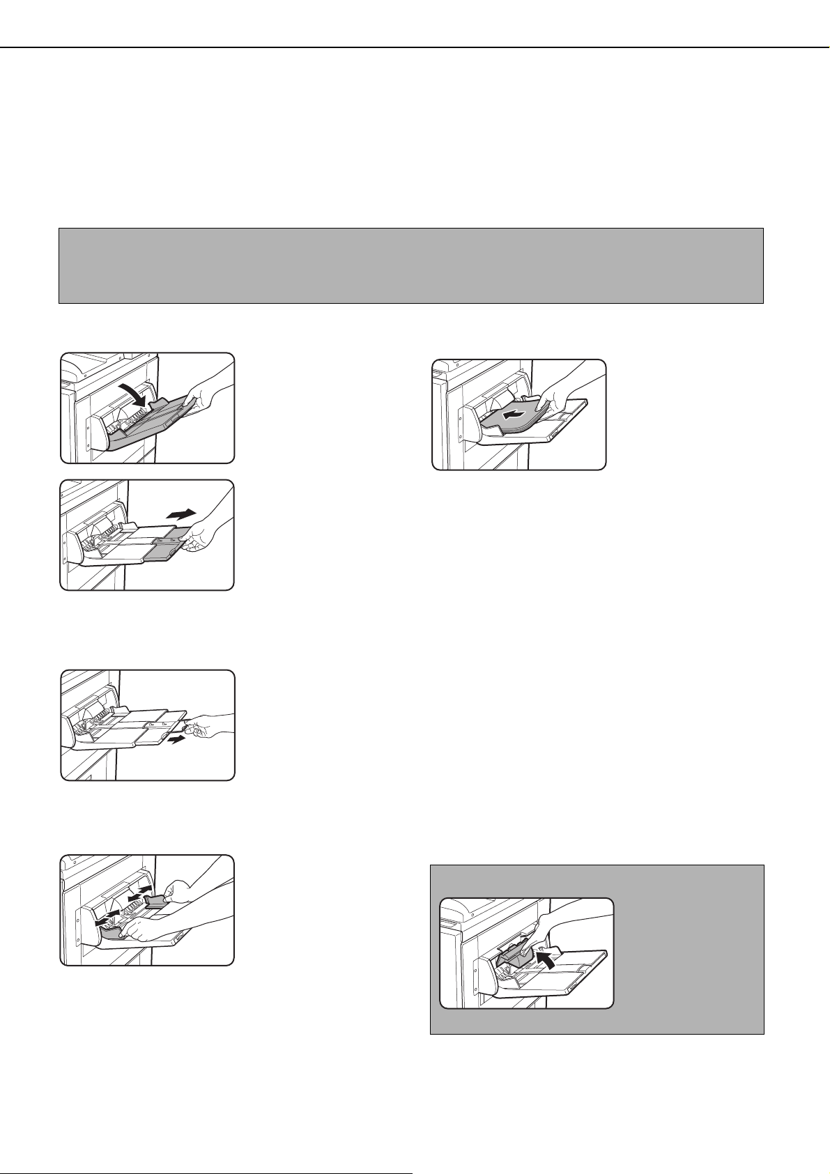
Open the bypass tray.
1
When loading paper that
will extend past the end
of the tray, pull out the
tray extension to support
the paper and to allow the
paper sensors to properly
sense the paper size.
Be sure to pull the tray extension all the way out. If
the tray extension is not pulled all the way out, the
size of the paper loaded in the bypass tray may not
display correctly.
To support papers that
extend past the tray
extension, pull out the
wire extension.
Insert the copy paper all the way into the
3
bypass tray. (Do not force the paper in.)
Place the copy paper
face up. If the bypass
tray guides are set
wider than the copy
paper, the inside of the
machine may become
soiled, resulting in
smudges on succeeding copies. Special purpose
papers other than SHARP recommended
transparency film must be fed individually. Multiple
sheets of SHARP recommended transparency
film can be loaded in the bypass tray.
Set the type and size of the paper loaded in
4
the bypass tray.
If you loaded a different type of paper from the
previous paper, be sure to set the new paper type
as explained in "Setting the paper type and paper
size in the bypass tray" (page 2-12). If you loaded
a special size of paper in the bypass tray, set the
paper size as explained in "Setting the paper type
and paper size in the bypass tray" (page 2-12).
(If you do not set a size, part or all of the image
may not print.)
Set the bypass tray guides to the width of
2
the copy paper.
2-4
This completes the procedure for loading
5
paper in the bypass tray.
NOTE
When loading paper in
the bypass tray or
closing the tray, close
the paper cover as
shown.
NOTES
● Be sure to load 5-1/2" x 8-1/2" paper, A6 paper, A5
paper, and postcards as shown in the diagram
below.
LOADING PAPER
A6 paper, post cards.
5-1/2" x 8-1/2" paper, A5 paper.
● When loading plain paper other than paper
recommended for color, SHARP standard paper,
special media other than postcards, SHARPrecommended transparency film, or paper to be
printed on the back, the paper must be loaded one
sheet at a time. Loading more than one sheet at a
time will cause misfeeds.
● Before loading heavy paper, straighten any curling
in the paper.
● When adding paper, remove any paper remaining
in the tray, combine it with the paper to be added,
and reload as a single stack.
● Do not use paper that has already been printed on
by a plain paper fax machine or a laser printer.
This may cause printed images to become dirty.
● When printing on transparency film, be sure to
remove each sheet as it exits the machine.
Allowing sheets to stack in the output tray may
cause curling.
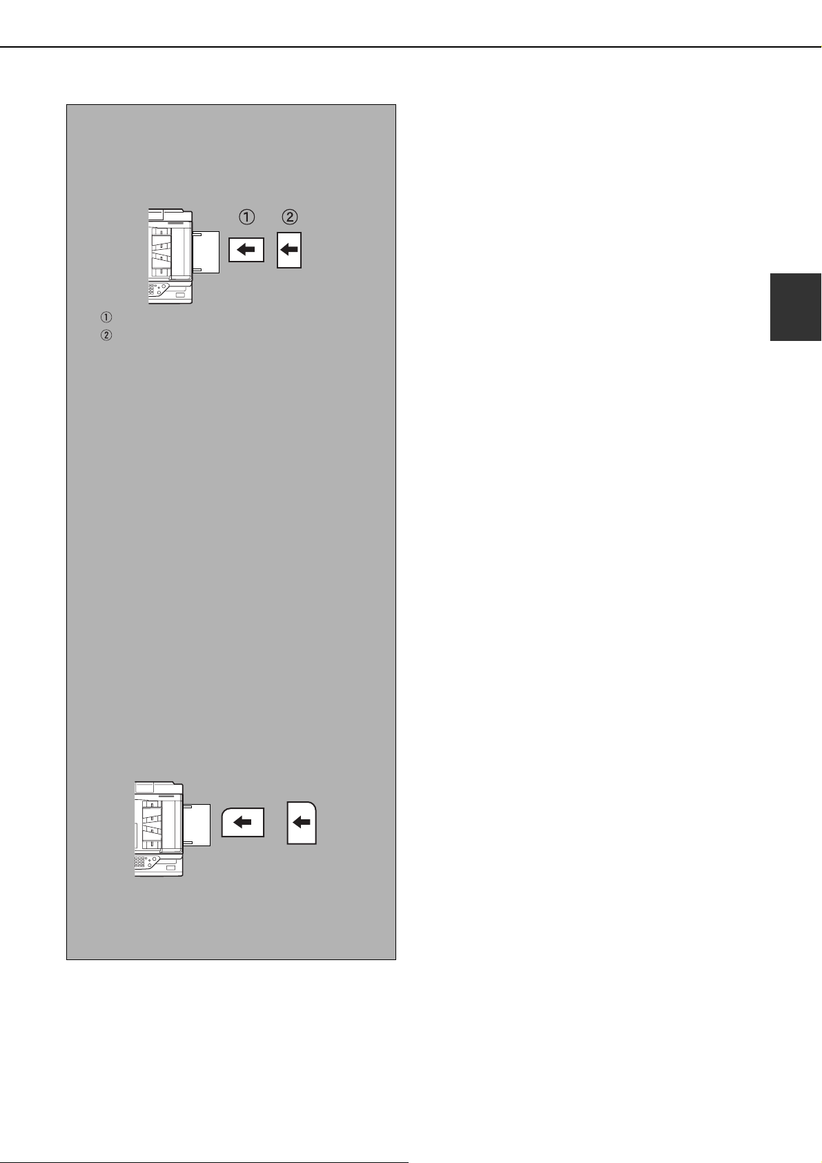
● Use only SHARP-recommended transparency
film. Insert the film so that the rounded corner is on
the left for horizontal loading, or on the right for
vertical loading.
2
Horizontal
loading
● When loading multiple sheets of transparency film
in the bypass tray, fan the sheets several times
before loading.
Vertical
loading
2-5
LOADING PAPER
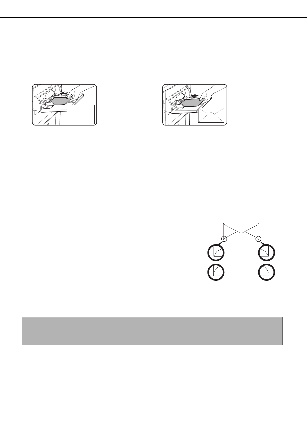
■■■■ Setting envelopes or postcards
When setting envelopes or postcards in the bypass tray, set them in the orientation shown below.
Loading postcards
Insert the postcard with the side to be printed on
facing up. The postcard should be oriented as
shown in the diagram.
Loading envelopes
Only the front side of envelopes can be printed.
Insert the envelope with the front side facing up.
Printing onto envelopes or postcards
●Attempting to print onto both sides of envelopes or postcards may result in misfeeds or poor prints.
●Do not use pre-printed envelopes.
●Before inserting a postcard or envelope, straighten any curled edges. Curled edges may cause creases, color
deviations, misfeeds, and poor quality images.
Printing onto envelopes
●Attempting to print on envelopes that have metal clasps, plastic snaps, string closures, windows, linings, selfadhesive patches or synthetic materials may cause misfeeds, inadequate toner adherence or other trouble.
●Envelopes with embossed surfaces may cause the prints to become smudged.
●Use only envelopes which are flat and crisply folded. Curled or poorly formed envelopes may be poorly printed
or may cause misfeeds.
●Print quality is not guaranteed in the area 13/32" or 10 mm from the
edges of the envelope.
●Print quality is not guaranteed on parts of envelopes where there is a
large step-like change of thickness, such as on three-layer or four-layer
envelopes.
●Print quality is not guaranteed on envelopes having peel off flaps for
sealing the envelopes.
Can be used
Cannot be used
Fusing unit pressure adjusting levers
In some cases damage to the envelopes, color deviations, or smudging may occur even if envelopes within the
specifications are used. This problem may be reduced by shifting the fusing unit pressure adjusting levers from
their normal pressure position to the lower pressure position. Follow the procedure on the next page. (2-7)
NOTE
Be sure to return the lever to the normal position when you have finished feeding envelopes. If not, inadequate
toner adherence, paper misfeeds or other trouble may occur.
2-6
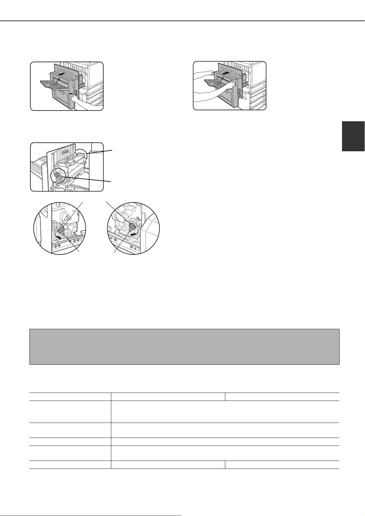
LOADING PAPER
Unlatch the duplex bypass/inverter unit
1
and slide it to the left.
Unlatch the unit and
gently move it away from
the machine. If the
machine is not equipped
with a duplex bypass/
inverter unit, open the
side cover similarly.
Lower the two fusing unit pressure
2
adjusting levers marked A and B in the
illustration.
A
B
Normal
position
Gently close the duplex bypass/inverter
3
unit.
If the machine is not
equipped with a duplex
bypass/inverter unit,
close the side cover.
2
B:Front side of
fusing unit
Lower pressure
position
A:Rear side of
fusing unit
Loading paper in the stand/1 x 500 sheet paper drawer/ stand/3 x 500 sheet paper drawer
Upper tray / middle tray / lower tray*
Up to 500 sheets of paper recommended for color or SHARP recommended plain paper can be loaded in these trays.
The method of loading paper is the same as for paper tray 1 in the main unit (see the explanation on page 2-2).
* The stand/1 x 500 sheet paper drawer only has the upper tray.
NOTE
If the size of paper being loaded is different from the previous size, or is an extra size, or if the paper type is different
from the previous type, you must change the paper tray settings in the custom settings. Change the settings as
explained in "Setting the paper type" and "Setting the paper size when an extra size is loaded" on page 2-11.
Specifications (stand/1 x 500 sheet paper drawer/stand/3 x 500 sheet paper drawer)
Name
Paper size/weight
Paper capacity
Power supply Supplied from the main unit
Dimensions
Weight Approximately 49.6 lbs. or 22.5 kg Approximately 65.0 lbs. or 29.5 kg
Specifications are subject to change for improvement without notice.
Stand/1 x 500 sheet paper drawer (AR-D17N) Stand/3 x 500 sheet paper drawer (AR-D18N)
11" x 17", 8-1/2" x 14", 8-1/2" x 13", 8-1/2" x 11", 8-1/2" x 11"R,
7-1/4" x 10-1/2"R, 5-1/2" x 8-1/2", Extra. (A3, B4, A4, A4R, B5, B5R, A5)
/ 17 to 28 lbs. or 64 to 105 g/m
Paper recommended for color (21 lbs. or 80 g/m
SHARP standard paper (21 lbs. or 80 g/m
23-5/8" (W) x 25-9/32" (D) x 15-7/8" (H) (600 mm (W) x 642 mm (D) x 403 mm (H))
(not including the adjuster)
2
2
): 500 sheets;
2
): 500 sheets
2-7

LOADING PAPER
Loading paper in the duplex module/2 x 500 sheet paper drawer
Upper tray:
The upper tray contains a duplex module that automatically turns print paper over for automatic two-sided printing.
Middle and lower paper trays:
The middle and lower trays are paper trays.
Up to 500 sheets of paper recommended for color or SHARP recommended plain paper can be loaded in these trays.
The method of loading paper is the same as for paper tray 1 in the main unit. See the explanation on page 2-2.
NOTE
If the size of paper being loaded is different from the previous size, or is an extra size, or if the paper type is different
from the previous type, you must change the paper tray settings in the custom settings. Change the settings as
explained in "Setting the paper type" and "Setting the paper size when an extra size is loaded" on page 2-11.
Specifications (duplex module/2 x 500 sheet paper drawer)
Name Duplex module/2 x 500 sheet paper drawer (AR-D19N)
11" x 17", 8-1/2" x 14", 8-1/2" x 13", 8-1/2" x 11", 8-1/2" x 11"R, 7-1/4" x 10-1/2"R,
Paper size/weight
Paper capacity
Power supply Supplied from the main unit
Dimensions
Weight Approximately 68.3 lbs. or 31 kg
Duplex module
Size of plain paper
Weight of plain paper 17 to 54 lbs. or 64 to 200 g/m
Number of sheets One sheet (single pass type)
Specifications are subject to change for improvement without notice.
5-1/2" x 8-1/2", Extra. (A3, B4, A4, A4R, B5, B5R, A5)
/ 17 to 28 lbs. or 64 to 105 g/m
Paper recommended for color (21 lbs. or 80 g/m
SHARP standard paper (21 lbs. or 80 g/m
23-5/8" (W) x 25-9/32" (D) x 15-7/8" (H) (600 mm (W) x 642 mm (D) x 403 mm (H))
11" x 17", 8-1/2" x 14", 8-1/2" x 13", 8-1/2" x 11", 8-1/2" x 11"R, 7-1/4" x 10-1/2R",
5-1/2" x 8-1/2", A3, B4, A4, A4R, B5, B5R, A5
2
2
): 500 sheets
(not including the adjuster)
2
2
): 500 sheets;
2-8
 Loading...