

Page 1
CODE: 00ZAR507//A1E
Digital Copier
(AR-250)
(AR-280/281) (AR-285/286/335/336)
AR-250
AR-280/281
AR-285/286/287
(AR-287/337)
(AR-405)
(AR-407)
AR-335/336/337
AR-405/407
MODEL AR-501/505/507
(AR-501/505)
[ 1 ] GENERAL . . . . . . . . . . . . . . . . . . . . . . . . . . . . . . . . . . . . . . . . . 1-1
[ 2 ] SPECIFICATIONS. . . . . . . . . . . . . . . . . . . . . . . . . . . . . . . . . . . 2-1
(AR-507)
CONTENTS
[ 3 ] CONSUMABLE PARTS. . . . . . . . . . . . . . . . . . . . . . . . . . . . . . . 3-1
[ 4 ] INSTALLATION AND SETUP . . . . . . . . . . . . . . . . . . . . . . . . . . 4-1
[ 5 ] EXTERNAL VIEW AND INTERNAL STRUCTURE. . . . . . . . . . 5-1
[ 6 ] SETTING AND ADJUSTMENTS. . . . . . . . . . . . . . . . . . . . . . . . 6-1
[ 7 ] SIMULATION. . . . . . . . . . . . . . . . . . . . . . . . . . . . . . . . . . . . . . . 7-1
[ 8 ] DISASSEMBLY, ASSEMBLY, MAINTENANCE . . . . . . . . . . . . 8-1
[ 9 ] TROUBLE CODE LIST . . . . . . . . . . . . . . . . . . . . . . . . . . . . . . . 9-1
[10] OPERATIONAL DESCRIPTION . . . . . . . . . . . . . . . . . . . . . . . 10-1
[11] SPECIAL FUNCTIONS (AR-287/337/407/507). . . . . . . . . . . . 11-1
This document has been published to be used
for after sales service only.
The contents are subject to change without notice.
Page 2

[1] GENERAL
1. Features of copying functions. . . . . . . . . . . . . . . . . . . . . 1-1
2. System outline (Options). . . . . . . . . . . . . . . . . . . . . . . . . 1-3
3. Installation requirements. . . . . . . . . . . . . . . . . . . . . . . . 1-10
[2] SPECIFICATIONS
1. Machine type. . . . . . . . . . . . . . . . . . . . . . . . . . . . . . . . . . 2-1
2. Copy speed. . . . . . . . . . . . . . . . . . . . . . . . . . . . . . . . . . . 2-1
3. 3. OC/DF. . . . . . . . . . . . . . . . . . . . . . . . . . . . . . . . . . . . . 2-1
4. Paper feed . . . . . . . . . . . . . . . . . . . . . . . . . . . . . . . . . . . 2-3
5. Multi copy . . . . . . . . . . . . . . . . . . . . . . . . . . . . . . . . . . . . 2-3
6. Warm up . . . . . . . . . . . . . . . . . . . . . . . . . . . . . . . . . . . . . 2-3
7. Copy magnification ratio . . . . . . . . . . . . . . . . . . . . . . . . . 2-3
8. Exposure. . . . . . . . . . . . . . . . . . . . . . . . . . . . . . . . . . . . . 2-3
9. Print area . . . . . . . . . . . . . . . . . . . . . . . . . . . . . . . . . . . . 2-3
10. Paper exit . . . . . . . . . . . . . . . . . . . . . . . . . . . . . . . . . . . . 2-3
11. Duplex module
(AR-285/286/287/335/336/337/405/407/501/505/507) . . 2-4
12. Shipping form . . . . . . . . . . . . . . . . . . . . . . . . . . . . . . . . . 2-4
13. Additional functions. . . . . . . . . . . . . . . . . . . . . . . . . . . . . 2-4
14. Options . . . . . . . . . . . . . . . . . . . . . . . . . . . . . . . . . . . . . . 2-5
15. Other specifications. . . . . . . . . . . . . . . . . . . . . . . . . . . . . 2-5
16. Outlook . . . . . . . . . . . . . . . . . . . . . . . . . . . . . . . . . . . . . . 2-5
17. Power supply . . . . . . . . . . . . . . . . . . . . . . . . . . . . . . . . . 2-5
18. Power consumption . . . . . . . . . . . . . . . . . . . . . . . . . . . . 2-5
19. Environmental measures . . . . . . . . . . . . . . . . . . . . . . . . 2-5
20. Combination of functions . . . . . . . . . . . . . . . . . . . . . . . . 2-6
[3] CONSUMABLE PARTS
1. Consumable Parts List . . . . . . . . . . . . . . . . . . . . . . . . . . 3-1
2. Copy paper . . . . . . . . . . . . . . . . . . . . . . . . . . . . . . . . . . 3-11
3. Environment conditions. . . . . . . . . . . . . . . . . . . . . . . . . 3-11
4. Production number identification. . . . . . . . . . . . . . . . . . 3-11
[4] INSTALLATION AND SETUP
(Copier installation) . . . . . . . . . . . . . . . . . . . . . . . . . . . . . . . . 4-1
1. Unpacking procedures . . . . . . . . . . . . . . . . . . . . . . . . . . 4-1
2. Installing procedure. . . . . . . . . . . . . . . . . . . . . . . . . . . . . 4-3
[5] EXTERNAL VIEW AND INTERNAL STRUCTURE
1. Common section. . . . . . . . . . . . . . . . . . . . . . . . . . . . . . . 5-1
A. Exterior . . . . . . . . . . . . . . . . . . . . . . . . . . . . . . . . . . . 5-1
B. Interior . . . . . . . . . . . . . . . . . . . . . . . . . . . . . . . . . . . . 5-1
C. Operation Panel. . . . . . . . . . . . . . . . . . . . . . . . . . . . . 5-2
2. Copier body. . . . . . . . . . . . . . . . . . . . . . . . . . . . . . . . . . . 5-3
A. Major parts. . . . . . . . . . . . . . . . . . . . . . . . . . . . . . . . . 5-3
B. PWB location. . . . . . . . . . . . . . . . . . . . . . . . . . . . . . . 5-4
C. Sensor location . . . . . . . . . . . . . . . . . . . . . . . . . . . . . 5-5
D. Motor location . . . . . . . . . . . . . . . . . . . . . . . . . . . . . . 5-6
E. Clutch solenoid . . . . . . . . . . . . . . . . . . . . . . . . . . . . . 5-6
F. 2-tray paper exit unit . . . . . . . . . . . . . . . . . . . . . . . . . 5-7
G. SPF (AR-280/281 only) . . . . . . . . . . . . . . . . . . . . . . . 5-7
H. RADF
(AR-285/286/287/335/336/337/405/407 only) . . . . . . 5-8
I. RSPF (AR-501/505/507 only) . . . . . . . . . . . . . . . . . . 5-9
J. ADU (AR-285/335/505/507 only). . . . . . . . . . . . . . . 5-10
[6] SETTING AND ADJUSTMENTS
1. List of adjustment items . . . . . . . . . . . . . . . . . . . . . . . . . 6-1
2. Copier adjustment. . . . . . . . . . . . . . . . . . . . . . . . . . . . . . 6-2
A. Process section . . . . . . . . . . . . . . . . . . . . . . . . . . . . 6-2
CONTENTS
B. Laser scanner section . . . . . . . . . . . . . . . . . . . . . . . . 6-7
C. Scanner section . . . . . . . . . . . . . . . . . . . . . . . . . . . . 6-9
D. Image density adjustment . . . . . . . . . . . . . . . . . . . . 6-16
E. Paper feed. . . . . . . . . . . . . . . . . . . . . . . . . . . . . . . . 6-18
F. Paper transport . . . . . . . . . . . . . . . . . . . . . . . . . . . . 6-18
F. Resist amount adjustment. . . . . . . . . . . . . . . . . . . . 6-19
G. Others . . . . . . . . . . . . . . . . . . . . . . . . . . . . . . . . . . . 6-19
H. SPF . . . . . . . . . . . . . . . . . . . . . . . . . . . . . . . . . . . . . 6-21
I. RADF. . . . . . . . . . . . . . . . . . . . . . . . . . . . . . . . . . . . 6-24
J. RADF (AR-RF2) . . . . . . . . . . . . . . . . . . . . . . . . . . . 6-27
[7] SIMULATION
1. Outline and purpose . . . . . . . . . . . . . . . . . . . . . . . . . . . . 7-1
2. Code system simulation . . . . . . . . . . . . . . . . . . . . . . . . . 7-1
A. Operating procedures and operations. . . . . . . . . . . . 7-1
B. List. . . . . . . . . . . . . . . . . . . . . . . . . . . . . . . . . . . . . . . 7-3
C. Details of simulations. . . . . . . . . . . . . . . . . . . . . . . . . 7-6
[8] DISASSEMBLY, ASSEMBLY, MAINTENANCE
1 Maintenance table. . . . . . . . . . . . . . . . . . . . . . . . . . . . . . 8-1
2. List of disassembly and assembly . . . . . . . . . . . . . . . . . 8-4
3. Counter clear . . . . . . . . . . . . . . . . . . . . . . . . . . . . . . . . . 8-4
A. Developing unit . . . . . . . . . . . . . . . . . . . . . . . . . . . . . 8-4
B. Drum unit. . . . . . . . . . . . . . . . . . . . . . . . . . . . . . . . . . 8-6
C. Discharge lamp . . . . . . . . . . . . . . . . . . . . . . . . . . . . 8-10
D. Scanner unit (Optical system) . . . . . . . . . . . . . . . . . 8-10
E. ICU peripheral . . . . . . . . . . . . . . . . . . . . . . . . . . . . . 8-14
F. Laser unit. . . . . . . . . . . . . . . . . . . . . . . . . . . . . . . . . 8-15
G. Manual paper feed tray unit. . . . . . . . . . . . . . . . . . . 8-16
H. 500 tray paper unit. . . . . . . . . . . . . . . . . . . . . . . . . . 8-17
I. Paper transport section . . . . . . . . . . . . . . . . . . . . . . 8-18
J. Suction unit . . . . . . . . . . . . . . . . . . . . . . . . . . . . . . . 8-19
K. Fusing unit. . . . . . . . . . . . . . . . . . . . . . . . . . . . . . . . 8-20
L. Two-tray paper exit unit. . . . . . . . . . . . . . . . . . . . . . 8-23
M. One-tray paper unit . . . . . . . . . . . . . . . . . . . . . . . . . 8-24
N. PCU/AC power/High voltage power/Main motor . . . 8-25
O. Major drive unit . . . . . . . . . . . . . . . . . . . . . . . . . . . . 8-26
P. Lift-up unit . . . . . . . . . . . . . . . . . . . . . . . . . . . . . . . . 8-28
Q. RSPF. . . . . . . . . . . . . . . . . . . . . . . . . . . . . . . . . . . . 8-28
[9] TROUBLE CODE LIST
1. Trouble code. . . . . . . . . . . . . . . . . . . . . . . . . . . . . . . . . . 9-1
2. Self diagnostics. . . . . . . . . . . . . . . . . . . . . . . . . . . . . . . . 9-2
3. Jam Cause Code . . . . . . . . . . . . . . . . . . . . . . . . . . . . . 9-11
[10] OPERATIONAL DESCRIPTION
1. Outline and purpose . . . . . . . . . . . . . . . . . . . . . . . . . . . 10-1
2. Image forming section correction operation
(Process correction operation) . . . . . . . . . . . . . . . . . . . 10-1
3. Details. . . . . . . . . . . . . . . . . . . . . . . . . . . . . . . . . . . . . . 10-1
4. RSPF . . . . . . . . . . . . . . . . . . . . . . . . . . . . . . . . . . . . . . 10-5
[11] SPECIAL FUNCTIONS (AR-287/337/407/507)
1. Tandem function. . . . . . . . . . . . . . . . . . . . . . . . . . . . . . 11-1
2. Confidential print. . . . . . . . . . . . . . . . . . . . . . . . . . . . . . 11-2
3. Large volume document mode . . . . . . . . . . . . . . . . . . . 11-3
4. Security function . . . . . . . . . . . . . . . . . . . . . . . . . . . . . . 11-3
5. Network Scanning. . . . . . . . . . . . . . . . . . . . . . . . . . . . . 11-4
6. E-mail Status/E-mail Alerts. . . . . . . . . . . . . . . . . . . . . . 11-5
Page 3
[1] GENERAL
1. Features of copying functions
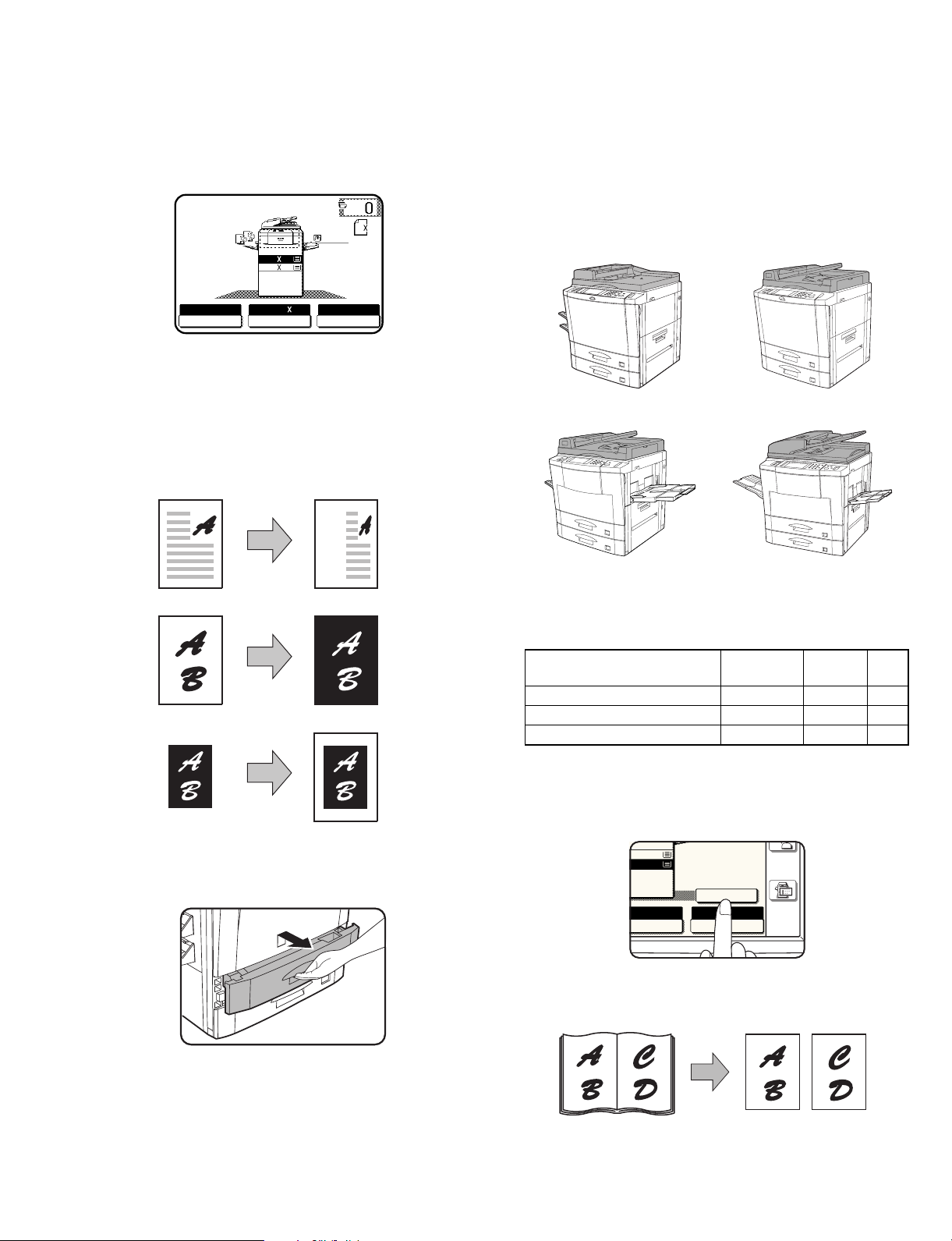
A. Touch panel
The touch panel with the back-lighted LCD simplifies various operations. It also shows operation descriptions and paper jam treatment.
READY TO COPY. (DOCUMENT FEEDER MODE)
1
8/ 11
ORIGINAL
2
1
1.8/ 11
2
2.11 17
AUTO
EXPOSURE PAPER SELECT
B. Various functions of digital system
Different from the conventional analog copiers, this machine employs
the digital system where the image data of a document scanned by
the CCD sensor (which converts photo signals into electrical signals)
are converted into digital signals. This digital system allows the independent zooming copy, black-white reversing copy, and centering
copy.
Independent zooming copy
1
AUTO 8/ 11
2
100%
COPY RATIO
D. Automatic document feeder as standard
provision
Without opening the document table cover, documents can be automatically fed and copied.
The automatic document feeder provided in the AR-280/285/286/287/
335/336/337/405/407/501/505/507 allows automatic reversion of
documents for duplex copying as well as simplex copying.
(The automatic document feeder of the AR-280/281 allows only simplex copying.)
AR-280/285/335 AR-286/287/336/337
Black-white reversing copy
Centering copy
C. Front loading paper tray
The paper trays including the two-step paper feed desk employ a
front loading system to facilitate paper loading.
AR-405/407 AR-501/505/507
E. Step zooming
The zooming function allows selection of the magnification ratio as
follows.
Magnification
ratio
Increment Steps
AR-280/281 25% to 200% 1% 176
AR-250/285/286/287/335/336/337 25% to 800% 1% 776
AR-405/407/501/505/507 25% to 400% 1% 376
F. Paper/magnification ratio auto selection
When the desired magnification ratio is specified, the suitable paper
size is automatically selected by the original size detection function. If
the copy paper size is specified, then the suitable magnification ratio
is automatically selected.
8½X11
11 X 11
TO 8½X11
ER SELECT
AUTO IMAGE
100%
COPY RATIO
REVEW
G. 1-set 2-copy
The right and the left pages of a book, etc. can be copied onto two
sheets of paper continuously.
1 – 1 7/13/2000
Page 4
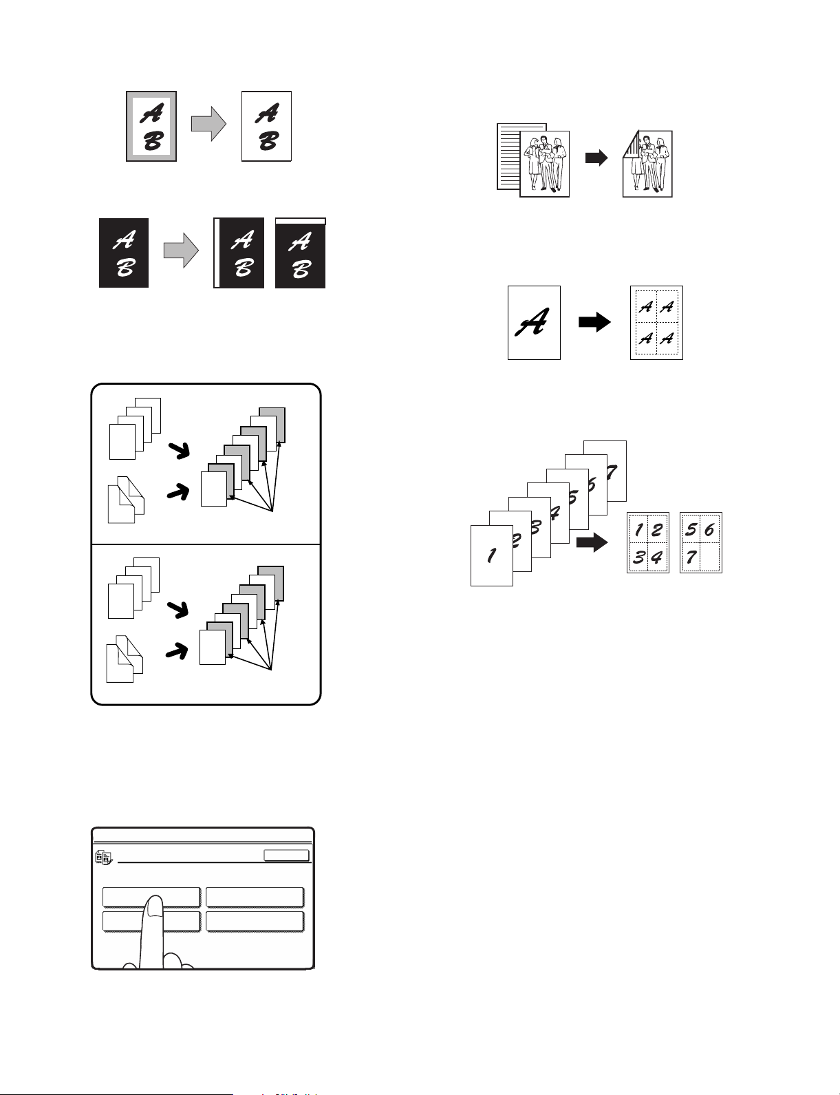
H. Edge erase copying
Shade at the copy edge can be automatically erased.
I. Binding margin copying
Copying with binding margin can be made.
J. Transparency film with insert sheets
When copying onto transparency film, insert sheets can be placed
following each transparent sheet. The insert sheets can be processed
blank or can be copied with the same image as the transparent
sheets.
4
3
2
1
2
1
3
1
4
2
1
4
4
3
3
2
INSERTS WITH
PRINTING
M. Auto duplex copy
(AR-250/280/281 requires the option)
Duplex copy is made automatically.
Original Copy
N. REPEAT COPY
The REPEAT COPY is used to produce repeated images from an
original on to a single sheet of paper. Border lines can be drawn to
separate repeated images.
O. MULTI SHOT
The MULTI SHOT function is used to copy several originals, collectively in a specified order, onto one sheet.
4
3
2
1
3
1
4
2
1
4
3
2
INSERTS WITHOUT
PRINTING
K. Copy conditions registration/recall
Nine sets of complicated copying procedures can be stored and recalled when necessary.
L. Key operator program
The key operator program is used by the key operator to set and
cancel the customer functions.
KEY OPERATOR PROGRAMS
COPIER MODE
OTHER FUNCTION
SETTINGS
ENABLE/DISABLE
SETTINGS
TIMER SETTINGS
ACCOUNT CONTROL
OK
P. Hi-Fi copy (AR-280/285/335 only)
This function produces high image quality copies.
Q. DATE SIGN
The DATE SIGN function adds the current date to the copies. The
date will be printed at the upper right of the copies.
R. WATERMARK
The WATERMARK function adds a selected watermark such as
“CONFIDENTIAL” and “URGENT” to the copies. The watermark will
be printed in gray tone at the center of copies.
S. SELECT STAMP
The SELECT STAMP function adds a selected string such as “CONFIDENTIAL” and “URGENT” to the copies. The string will be printed in
white on a shaded background.
T. PAGE NUMBER
The PAGE NUMBER function adds page numbers to the copies.
7/13/2000 1 – 2
Page 5

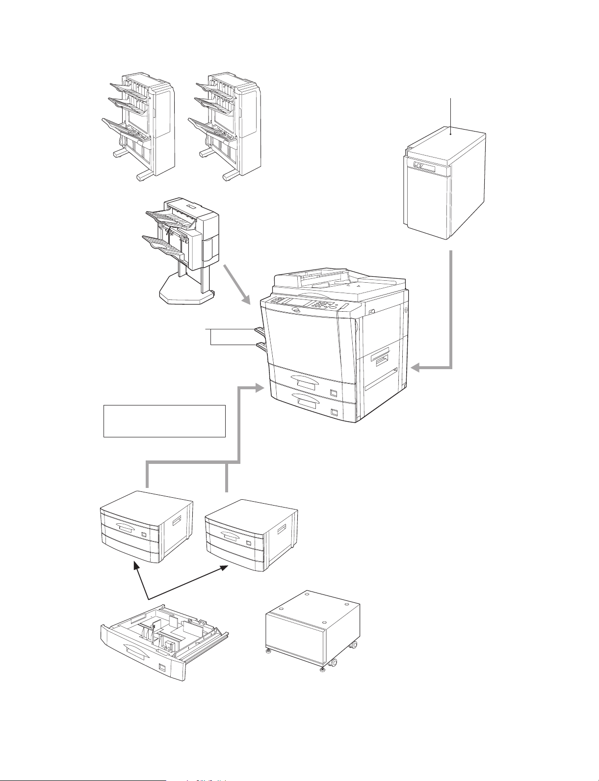
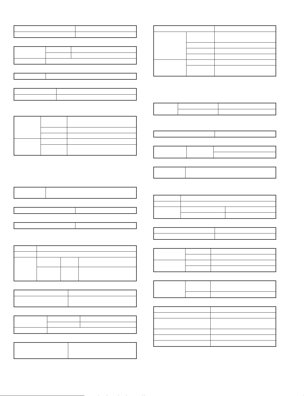
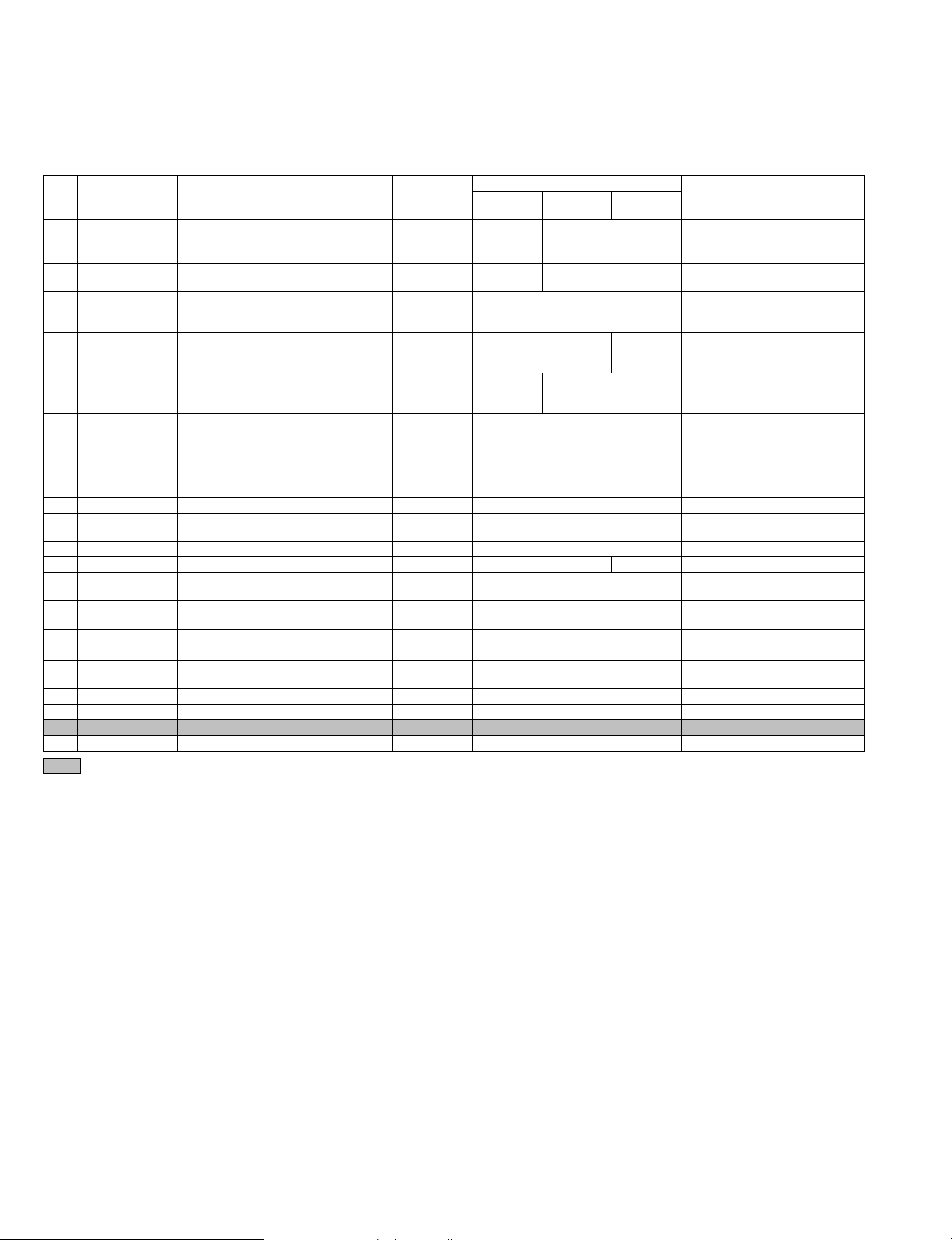
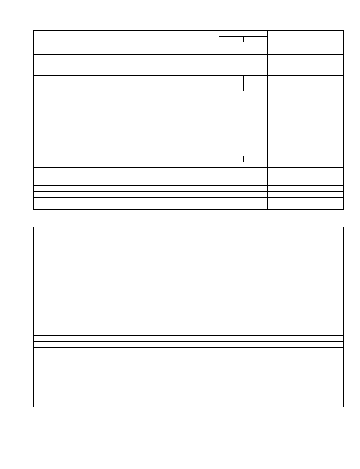
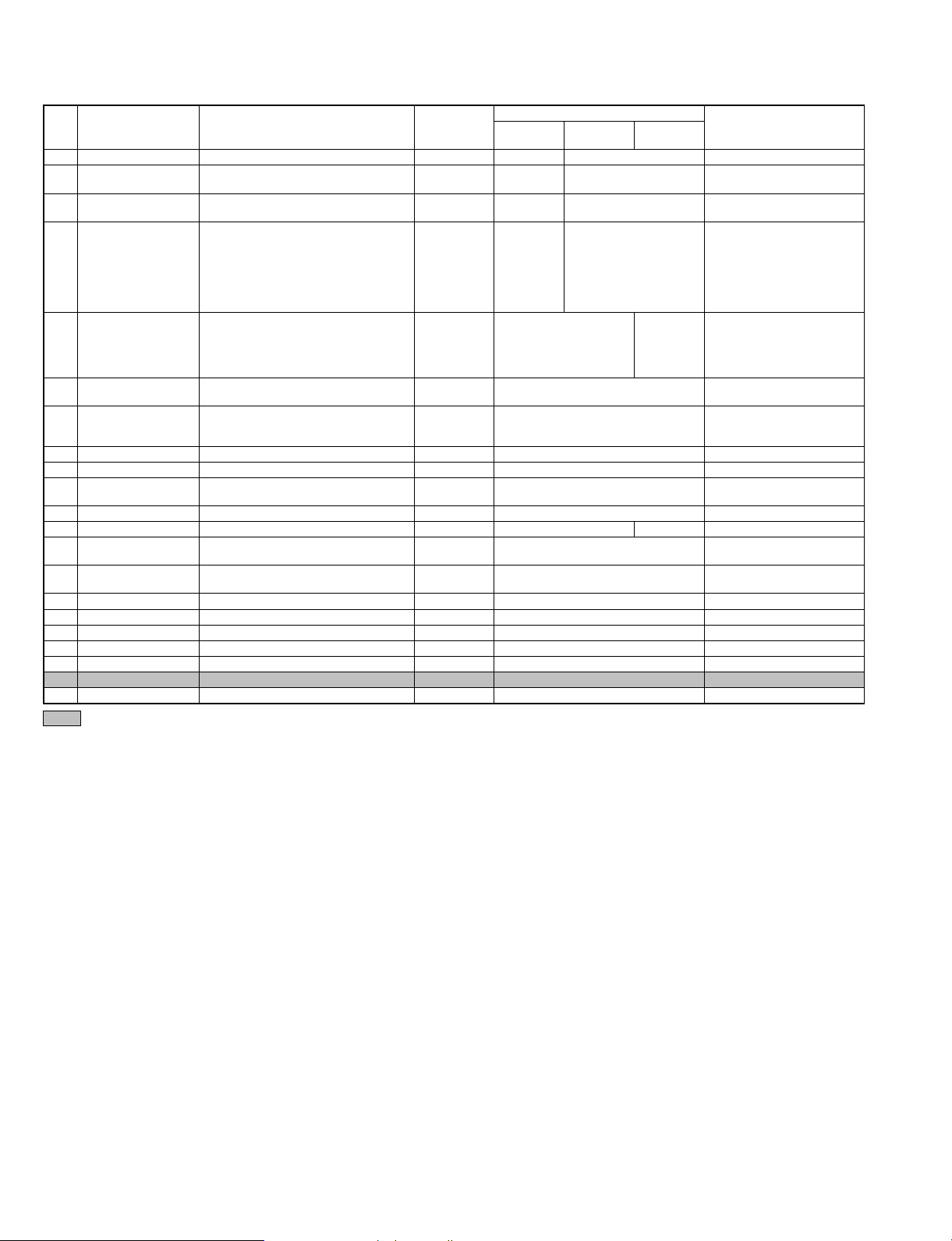
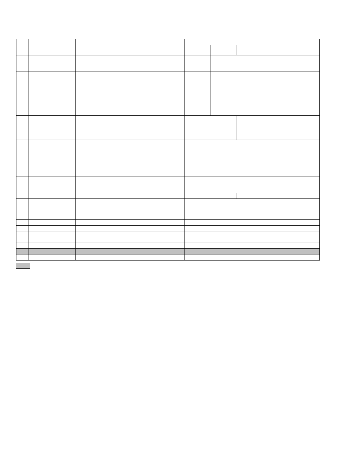
2. System outline (Options)
Copier model
Name Model AR-250 AR-280 AR-281 AR-285 AR-286 AR-287 AR-335 AR-336 AR-337 AR-405 AR-407 AR-501 AR-505 AR-507
Automatic
document
feeder
Reversing
automatic
document
feeder
Stand/500
sheet paper
drawer
Large
capacity tray
500-sheet
paper drawer
Desk AR-DD1 ❍❍❍❍❍❍❍❍❍— ❍❍❍ ❍
2-tray paper
exit unit
Exit tray AR-TE1 ❍ — ❍❍❍❍❍❍❍— ❍❍❍❍ (SEC/SECL)
Dual tray
output unit
Finisher AR-FN1 ❍❍ ❍❍❍— ❍❍————— —
Printer board AR-PB2 ❍❍ ❍❍❍— ❍❍— ❍ ——❍ —
NIC card (10
base T/2)
NIC card (10
base T/100
base TX)
AXIS fixing
angle
1GB-HDD AR-HD1 ❍ ———————————— —
Network
scanner kit
Mounting kit AR-XB3 — — ❍ — ❍❍ — ❍❍❍❍—— ❍
Document
cover
Tandem
connection
cable
Sharpdesk 5
license kit
Security ROM AR-FR1 — — — — — ❍ ——❍ ———— —
AR-SP1 ❍ Standard Standard — — ———————— —
RSPF———————————Standard Standard Standard
AR-RF1 ❍ ——❍❍Standard Standard Standard Standard ———— —
AR-RF2—————————Standard Standard — — —
AR-DE1 ❍❍ ❍❍❍— ❍❍————— —
AR-DE1N ❍❍❍❍❍❍❍❍❍❍❍—— —
AR-DE7———————————❍❍ ❍
AR-LC1 ❍❍ ❍❍❍— ❍❍— ❍ ——— —
AR-LC1N — ❍❍❍❍❍❍❍❍❍❍❍— ❍
AR-CS1 ❍❍❍❍❍❍❍❍❍❍❍—— —
AR-CS3———————————❍❍ ❍
AR-DD1N—————————❍ ——— —
AR-DU1 ❍❍ ❍— ❍ Standard — ❍ Standard — Standard — — Standard
AR-TE2———————————❍❍
AR-TR1 ❍ — ❍ — ❍❍ — ❍❍❍❍—— —
AR-FN1N ❍❍❍❍❍❍❍❍❍❍❍—— —
AR-FN2 ❍❍❍❍❍❍❍❍❍❍❍—— —
AR-FN3———————————❍❍ ❍
AR-PB2A — — — — — ❍ ——❍ — ❍ —— ❍
AR-SM1 — — — — — ❍ ——❍ — ❍ — ❍❍
JX96NCE8 ❍❍ ❍❍❍— ❍❍— ❍ ——❍ —
AR-NC1D ❍❍❍❍❍❍❍❍❍— ❍ — ❍❍
AR-NC3D ❍❍❍❍❍❍❍❍❍❍❍— ❍❍
AR-NC4D————————————— —
(AXIS
scanner)
AR-NS1 — — — — — ❍ ——❍ — ❍ —— ❍
AR-VR2 ❍ ———————————— —
AR-CA1 — — — — — — — — ❍ — ❍ — ❍❍
AR-U11M — — — — — ❍ ——❍ — ❍ —— ❍
AR-U15M — — — — — ❍ ——❍ — ❍ —— ❍
AR-FR2——————————❍ —— —
AR-FR3————————————— ❍
❍ — ❍ — ❍ ——❍ — ❍ ——❍ —
❍ (EX destinations
other than
SEC/SECL)
1 – 3 7/13/2000
Page 6
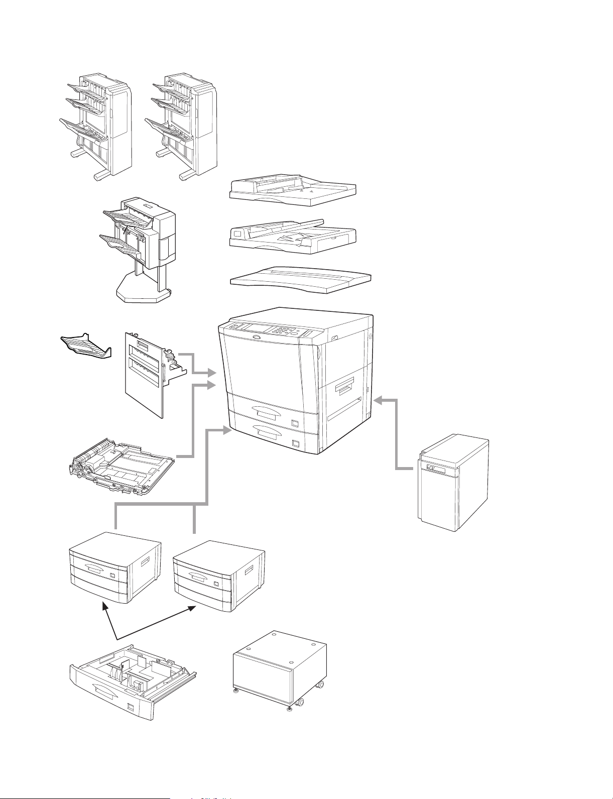
AR-250
Finisher
(AR-FN1)
Finisher
(AR-FN1N)
Exit tray
(AR-TE1)
Finisher
(AR-FN2)
Dual tray output unit
(AR-TR1)
Duplex module
(AR-DU1)
Automatic document feeder
(AR-SP1)
Reversing automatic document feeder
(AR-RF1)
Document cover
(AR-VR2)
Large capacity tray
(AR-LC1)
Stand/500 sheet
paper drawer
(AR-DE1)
500-sheet paper drawer
(AR-CS1)
7/13/2000 1 – 4
Stand/500 sheet
paper drawer
(AR-DE1N)
Desk (AR-DD1)
Printer expansion kit
·
(AR-PB2)
NIC card (10 base T/2) (Provided by Europe)
·
(JX96NCE8)
NIC card (10 base T/2) (Provided by local distributors)
·
(AR-NC1D)
NIC card (10 base T / 100 base TX)
·
(AR-NC3D)
AXIS fixing angle
·
(AXIS scanner)
Mounting kit
·
(AR-XB3)
1 GB HDD
·
(AR-HD1)
Page 7
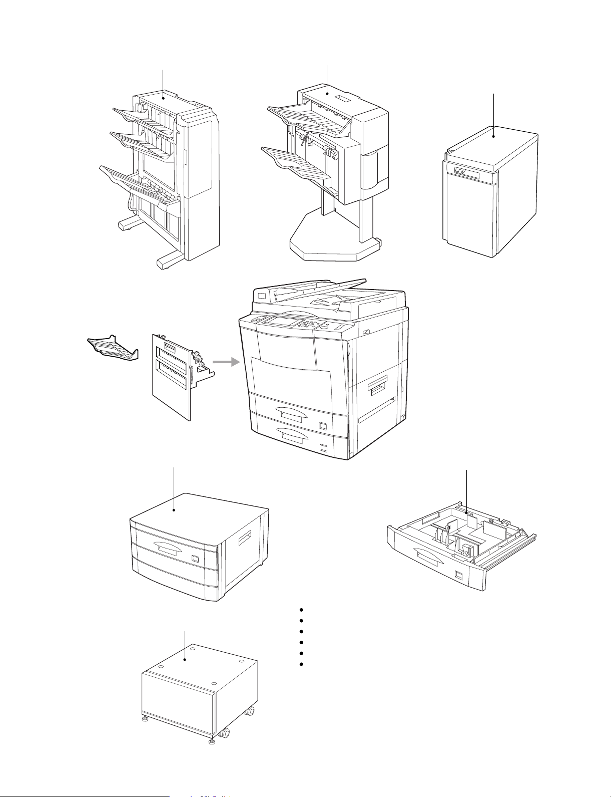
AR-280/285/335
Finisher
(AR-FN1)
Finisher
(AR-FN1N)
Large capacity (AR-LC1)
(AR-LC1N)
Finisher
(AR-FN2)
EXIT trays
(AR-TE1)
The duplex module (AR-DU1) is
provided as an optional component.
(AR-280)
Stand/500 sheet
paper drawer
(AR-DE1)
500-sheet paper drawer
(AR-CS1)
Stand/500 sheet
paper drawer
(AR-DE1N)
Desk (AR-DD1)
Printer expansion kit
·
(AR-PB2)
NIC card (10 base T/2) (Provided by Europe)
·
(JX96NCE8)
NIC card (10 base T/2) (Provided by local distributors)
·
(AR-NC1D)
NIC card (10 base T / 100 base TX)
·
(AR-NC3D)
1 – 5 7/13/2000
Page 8

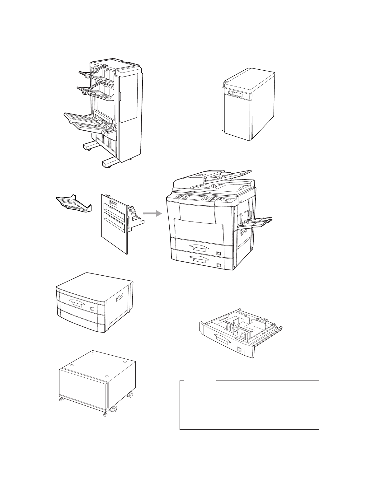
AR-281/286/336
Exit tray
(AR-TE1)
Finisher
(AR-FN1)
Dual tray output unit
(AR-TR1)
Finisher
(AR-FN1N)
Finisher
(AR-FN2)
AR-281
AR-286/336
2-tray paper exit unit (AR-281 only)
(AR-DU1)
Stand/500 sheet
paper drawer
(AR-DE1)
500-sheet paper drawer
(AR-CS1)
Stand/500 sheet
paper drawer
(AR-DE1N)
Desk (AR-DD1)
Large capacity
(AR-LC1)
(AR-LC1N)
Printer expansion kit
·
(AR-PB2)
NIC card (10 base T/2) (Provided by Europe)
·
(JX96NCE8)
NIC card (10 base T/2) (Provided by local distributors)
·
(AR-NC1D)
NIC card (10 base T / 100 base TX)
·
(AR-NC3D)
AXIS fixing angle
·
(AXIS scanner)
Mounting kit
·
(AR-XB3)
7/13/2000 1 – 6
Page 9
AR-405
Finisher (AR-FN1N)
Finisher (AR-FN2)
Large capacity tray (AR-LC1)
(AR-LC1N)
Exit tray
(AR-TE1)
Dual tray output unit
(AR-TR1)
Stand/500-sheet paper drawer (AR-DE1N)
500-sheet paper drawer (AR-CS1)
Desk (AR-DD1)
Printer board (AR-PB2)
NIC card(10baseT/2) (Provided by Europe) (JX96NCE8)
NIC card (10baseT/2) (Provided by Europe) (AR-NC1D)
NIC card (10baseT/100baseTX) (AR-NC3D)
AXIS fixing angle (AXIS scanner)
Mounting kit (AR-XB3)
1 – 7 7/13/2000
Page 10
AR-501/505
Exit tray
(AR-TE1)
(AR-TE2)
Finisher (AR-FN3)
Large capacity tray (AR-LC1N)
Dual tray output unit
(AR-TR1)
Stand/500-sheet paper drawer (AR-DE7)
Desk (AR-DD1)
500-sheet paper drawer (AR-CS3)
AR-505 only
Printer board (AR-PB2)
·
NIC card (10baseT/2) (Provided by Europe) (JX96NCE8)
·
NIC card (10baseT/2) (Provided by Europe) (AR-NC1D)
·
NIC card (10baseT/100baseTX) (AR-NC3D)
·
Printer board (Expansion memory 16MB x2 SIM) (AR-SM1)
·
AXIS fixing angle (AXIS scanner)
·
Tandem connection cable (AR-CA1)
·
7/13/2000 1 – 8
Page 11
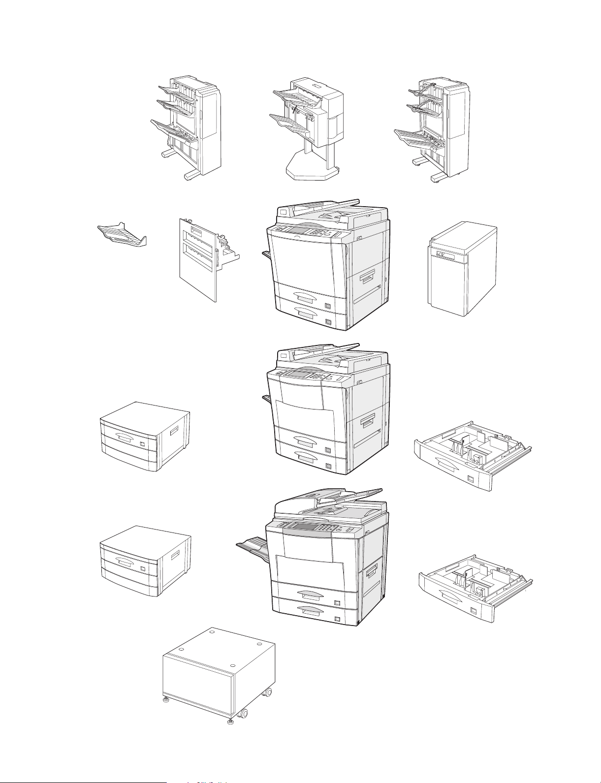
AR-287/337/407/507
Finisher:
AR-FN1N (AR-287/337/407)
Finisher:
AR-FN2 (AR-287/337/407)
Finisher:
AR-FN3 (AR-507)
Exit tray:
AR-TE1 (AR-287/337/407/507 (SEC/SECL))
AR-TE2 (AR-507 (Other than SEC/SECL))
Dual tray output unit:
AR-TR1
Stand/500 sheet
paper drawer:
AR-DE1N (AR-287/337/407)
AR-287/337
AR-407
Large capacity:
AR-LC1N (AR-287/337/407/507)
500-sheet paper drawer:
AR-CS1 (AR-287/337/407)
Stand/500-sheet
paper drawer:
AR-DE7 (AR-507)
Desk: AR-DD1
AR-507
500-sheet paper drawer:
AR-CS3 (AR-507)
Printer board: AR-PB2A
·
NIC card (10baseT/2)
·
AR-NC1D
NIC card (10 base T/100 base TX): AR-NC3D
·
Printer board (Expansion memory 16MB x2 SIM):
·
AR-SM1 (AR-507)
Network scanner kit: AR-NS1
·
Tandem connection cable AR-CA1
·
Mounting kit: AR-XB3 (AR-287/337/407)
·
Sharpdesk 5 license kit: AR-U11M/U15M
·
Security ROM: AR-FR1 (AR-287/337)
·
1 – 9 7/13/2000
(Provided by local distributors):
AR-FR2 (AR-407)
AR-FR3 (AR-507)
Page 12

3. Installation requirements
To ensure safety and proper machine performance, please note the
following before initial installation and whenever the machine is to be
relocated.
1) The copier should be installed near an accessible power outlet for
easy connection.
2) Be sure to connect the power cord only to a power outlet that
meets the specified voltage and current requirements.
Also make certain the outlet is properly grounded.
3) Do not install the machine where it is:
· damp or humid,
· exposed to direct sunlight,
· extremely dusty,
· poorly ventilated,
· subject to extreme temperature or humidity changes (e.g., near
an air conditioner or heater).
A small amount of ozone is produced within the copier during operation. The emission level is insufficient to cause any health hazard.
NOTE: The present recommended long term exposure limit for
ozone is 0.1 ppm (0.2 mg/m
weighted average concentration.
However, since the small amount that is emitted may have
an objectionable odor, it is advisable to place the copier in a
ventilated area.
3
) calculated as an 8 hr. time-
Cautions
1) Do not touch the photoconductive drum. Scratches or smudges on
the drum will cause dirty copies.
2) The fusing unit is extremely hot. Exercise care in this area.
3) Since a hard disk drive is built into the copier, be sure to turn the
power switch to the "OFF" position when moving the copier. Take
care not to subject the copier to any vibration or shock.
Fusing unit
Photoconductive
drum
4) Do not look directly at the light source. Doing so may damage
your eyes.
4) Since a hard disk drive is built into this copier, place the copier on
a firm, level surface. Choose an area which is not subject to any
vibration.
5) Be sure to allow the required space around the machine for servicing and proper ventilation.
11-13/16"
(30cm)
23-5/8"
(60cm)
23-5/8"
(60cm)
11-13/16"
(30cm)
5) Installation adjusters are provided on the optional stand/500-sheet
paper drawer.When moving the machine with the optional
stand/500-sheet paper drawer, be sure to raise the installation
adjusters. After moving the machine, lower the installation adjusters until they reach the floor to lock the machine in place. (If the
casters are not locked securely, the machine will gradually move
and the cables of the RADF and the SPF are rubbed against the
wall, causing internal disconnection.)
Caster
Release
Lock Release
Lock
Adjuster
6) When copying is interrupted (for example, because the INTERRUPT function has been used, paper or toner has run out, a
misfeed has occurred, etc.), this copier will store the image data of
the originals read prior to the interruption. If copying of secret
documents is interrupted due to the above reasons, be sure to
either resume the interrupted copying by pressing the START key,
or clear the image data by pressing the clear all key after the
interrupt copying is completed or the trouble is cleared, because
the stored data may be printed by other operators.
7/13/2000 1 – 10
Page 13

[2] SPECIFICATIONS
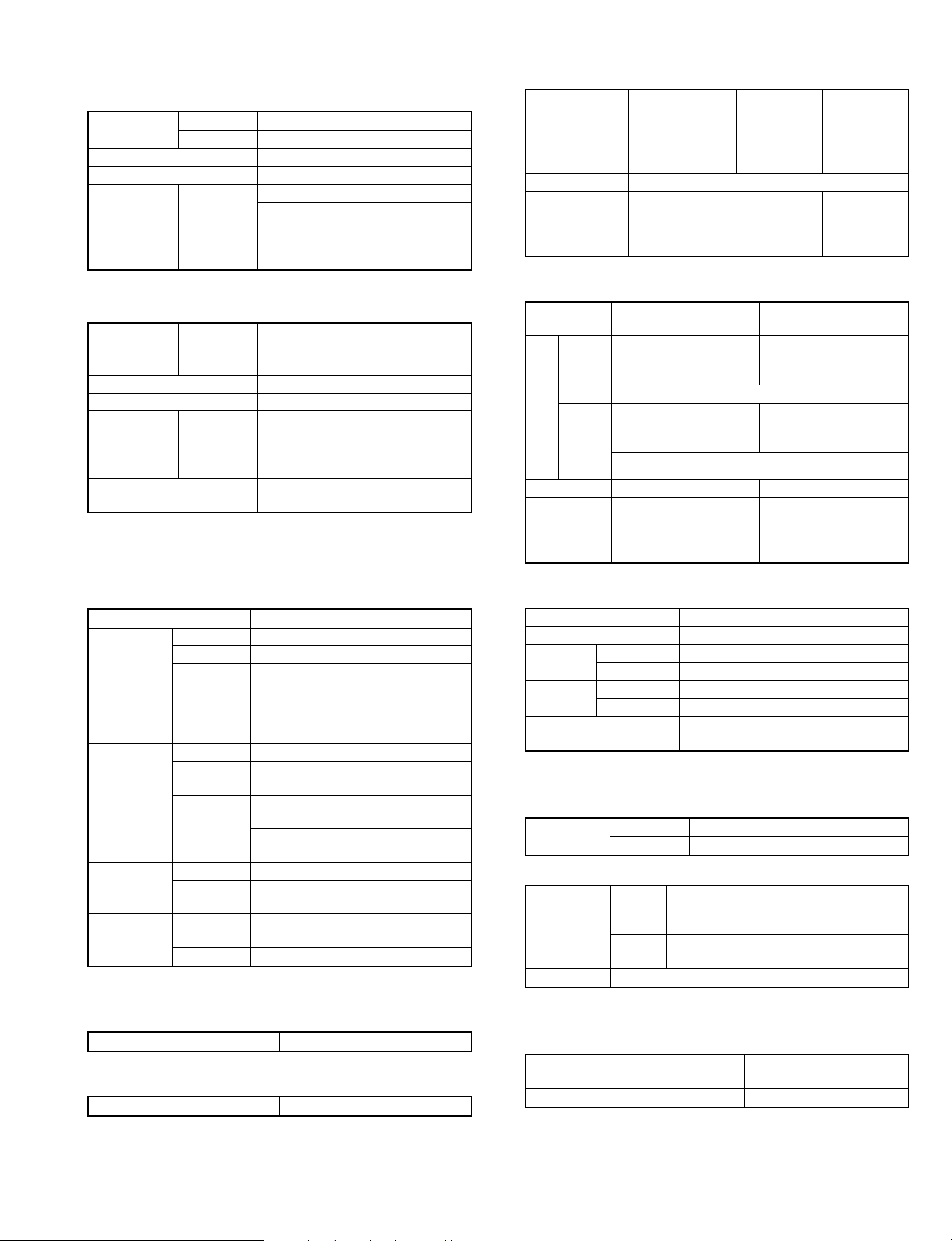
1. Machine type
Product
CPM Type
Name
AR-250 25 Simplex Desk top – 1 tray 48 MB –
AR-280 28 Simplex Desk top SPF 2 tray 16 MB 1 GB
AR-281 28 Simplex Desk top SPF 1 tray 16 MB 2 GB
AR-285 28 Duplex Desk top RADF 2 tray 16 MB 1 GB
AR-286 28 Duplex Desk top RADF 1 tray 16 MB 2 GB
AR-287 28 Duplex Desk top RADF 1 tray 32 MB 4.3 GB
AR-335 33 Duplex Desk top RADF 2 tray 16 MB 1 GB
AR-336 33 Duplex Desk top RADF 1 tray 16 MB 2 GB
AR-337 33 Duplex Desk top RADF 1 tray 32 MB 4.3 GB
AR-405 40 Duplex Desk top RADF 1 tray 16 MB 2 GB
AR-407 40 Duplex Desk top RADF 1 tray 32 MB 4.3 GB
AR-501 50 Duplex Desk top RSPF 1 tray 48 MB 2 GB
AR-505 50 Duplex Desk top RSPF 1 tray 48 MB 2 GB
AR-507 50 Duplex Desk top RSPF 1 tray 48 MB 4.3 GB
* Memory capacity is of the main body only, excluding optional
expansion memory.
* Standard’s spec.
2. Copy speed
A. Basic Speed
per 1 scan AR-250
Single 25 cpm 28 cpm 28 cpm 28 cpm 34 cpm 47 cpm
Multiple 25 cpm 28 cpm 28 cpm 33 cpm 40 cpm 50 cpm
* Speeds from all the paper feed ports including the normal copy
and the manual feed copy.
B. Normal copy (100%)
A4/8.5 ´ 11 25 28 28 33 40 50
A3/11 ´ 17 13 14 14 17 19 25
B4/8.5 ´ 14/
8.5 ´ 13
B5/A5/
8.5 ´ 5.5
A4R/B5R/
8.5 ´ 11
C. Enlargement copy
A4/8.5 ´ 11 25 28 28 33 40 50
A3/11 ´ 17 13 14 14 17 19 25
B4/8.5 ´ 14/
8.5 ´ 13
B5/A5/
8.5 ´ 5.5
A4R/B5R/
8.5 ´ 11
D. Reduction copy (25%)
A4/8.5 ´ 11 25 28 28 33 40 50
A3/11 ´ 17 13 14 14 17 17 25
B4/8.5 ´ 14/
8.5 ´ 13
B5/A5/
8.5 ´ 5.5
A4R/B5R/
8.5 ´ 11
AR-280
AR-281
AR-250
AR-250
AR-250
AR-280
AR-281
15 17 17 21 24 29
25 28 28 33 40 50
18 20 20 24 27 35
AR-280
AR-281
(800%)
15 17 17 21 24 29
25 28 28 33 40 50
18 20 20 24 27 35
AR-280
AR-281
15 17 17 21 24 29
25 28 28 33 40 50
18 20 20 24 27 35
Document
AR-285
AR-286
AR-287
AR-285
AR-286
AR-287
AR-285
AR-286
AR-287
(800%)
AR-285
AR-286
AR-287
Feeder
AR-335
AR-336
AR-337
AR-335
AR-336
AR-337
AR-335
AR-336
AR-337
(800%)
AR-335
AR-336
AR-337
Paper
Exit
RAM HD
AR-405
AR-407
AR-405
AR-407
AR-405
AR-407
(400%)
AR-405
AR-407
Memory
AR-501
AR-505
AR-507
AR-501
AR-505
AR-507
AR-501
AR-505
AR-507
(400%)
AR-501
AR-505
AR-507
E. First Copy time
(1) Basic Speed
Model AR-250
Speed (sec.) 5.2 5.2 5.2 5.2 4.5 4.3
AR-280
AR-281
AR-285
AR-286
AR-287
When the paper is fed from the Upper tray on the base unit.
Machines are measured when paper is fed from the upper tray of 2-
tray exit unit.
AR-335
AR-336
AR-337
AR-405
AR-407
AR-501
AR-505
AR-507
(2) Detail
AR-250
Upper cassette
(sec.)
Lower cassette
(sec.)
Multi-Baypass
Tray (sec.)
Stand/Upper paper drawer (sec.)
Stand/Medium
paper drawer
(sec.)
LCC (sec.) 5.9 5.9 5.9 5.9 5.2 4.7
AR-280
AR-281
5.2 5.2 5.2 5.2 4.5 4.3
5.7 5.7 5.7 5.7 5.0 4.5
5.3 5.3 5.3 5.3 4.6 4.3
6.6 6.6 6.6 6.6 5.9 5.2
6.9 6.9 6.9 6.9 6.2 5.5
AR-285
AR-286
AR-287
Refer to each specification for the first copy time when paper is fed
from the document feeder or the optional paper feed tray.
AR-335
AR-336
AR-337
AR-405
AR-407
AR-501
AR-505
AR-507
(3) First copy time from the document feeder
AR-250
Model
When the SPF is used
(sec.)
When the RADF is
used (sec.)
When the RSPF is
used (sec.)
AR-281
AR-286
AR-287
AR-280
7.87.8———
8.8 — 8.8 7.6 —
————7.0
When the paper is fed from the Upper tray on the base unit.
AR-285
AR-335
AR-336
AR-337
AR-405
AR-407
AR-501
AR-505
AR-507
3. OC/DF
A. Document table
Max. document size A3/11 ´ 17
Document reference position Center left
Document detection Yes
Inch Series
Detection size
AB Series A3, B4, A4, A4R, A5
Australia A3, 216 ´ 330, A4, A4R, A5 (Note 1)
B5 areas A3, B4, A4, A4R, B5, B5R
OR guide display
Inch Series 11, 8.5, 5.5
AB Series
(Note 1) For areas other than Australia, "B4/8.5 ´ 11" can be
changed to "8.5 ´ 13" by the simulation.
(Note 2) The display of 8.5" for AB series is of the line display only.
There is no size display.
B. SPF (AR-280/281)
(1) Document set
Set direction Face down
Set position Center reference
Set quantity
A4/8.5 ´ 11 30 sheets 30 sheets of 80g/m
Greater than
the above.
11 ´ 17, 8.5 ´ 14, 8.5 ´ 11,
8.5 ´ 11R, 8.5 ´ 5.5
A3/A4, B4/B5, A4R/A5, B5R,
11, 8.5 (Note 2)
15 sheets
For 80 ~ 128g/m
4.7mm thick can se set.
2
must be set.
2
, paper of max.
2 – 1 7/13/2000
Page 14
(2) Document transport
Document transport system Sheet through type
Document feed sequence Top take-up feed
(3) Document Size
Document Size
Paper Weight 50 ~ 128g/m
AB Series A3 ~ A5
Inch Series 11 ´ 17 ~ 8.5 ´ 5.5
2
(14 ~ 34 lbs.)
(4) Multi quantity
Multi quantity In the high fidelity mode, multi copy is inhibited.
(5) Document mix feed
Mix paper feed Allowed.
Random paper feed Not allowed.
No linkage with AMS is made.
(6) Document detection
Detection
size
Inch Series
AB Series A3, B4, A4, A4R, A5
Australia A3, A4, A4R, A5, 216 ´ 330 (Note 1)
Document
guide display
Inch Series 11, 8.5, 5.5
AB Series
(Note 1) For areas other than Australia, "B4/8.5 ´ 11" can be
changed to "8.5 ´ 13" by the simulation.
(Note 2) The display of 8.5" for AB series is of the line display only.
There is no size display.
11 ´ 17, 8.5 ´ 14, 8.5 ´ 11,
8.5 ´ 11R, 8.5 ´ 5.5
A3/A4, B4/B5, A4R/A5, B5R, 8.5
(Note 2)
(7) Stream mode
Stream mode
The stream mode can be selected by the key
operation program. (Only group mode)
(8) Document reverse
Document reverse No
(9) Display section
Display section No
C. RADF (AR-285/286/287/335/336/337/405/407)
(1) Document set
Set direction
Set position
Set quantity A4/8.5 ´ 11 50 sheets 35 ~ 80g/m2:
(2) Document transport system
Document transport system Belt system
Document fed sequence
(3) Document size
Document size
Weight 35 ~ 128g/m
(4) Document stop system
Document stop system
Face up
Center reference
Thickness Less than 6.5 mm
Greater than
the above
30 sheets 80 ~ 128g/m
Thickness Less than 5 mm
(50 sheets of 80g/m
Lower take-up paper feed
(Face up paper feed)
AB Series A3 ~ A5
Inch Series 11 ´ 17 ~ 8.5 ´ 5.5
2
(10 ~ 34 lbs.)
Stopper system
(Position control for single copy )
(Duplex copy)
2
:
2
)
(5) Document detection on the tray
Document detection on the tray Yes
Inch Series 11 ´ 17, 8.5 ´ 14, 8.5 ´ 11,
8.5 ´ 11R, 8.5 ´ 5.5, 8.5 ´ 13
Detection size
AB Series A3, B4, A4, A4R, A5, 8.5 ´ 13
B5 area A3, B4, A4, A4R, B5, B5R, A5
Australia A3, B4, A4, A4R, A5, 216 ´ 330
Document
guide display
Inch Series 11, 8.5, 5.5
AB Series A3/A4, B4/B5, A4R/A5, B5R,
8.5 (Note)
(Note) AB series 8.5" display is of line display only. Size display is
not made.
When setting Sim, "8.5 ´ 14" and "8.5 ´ 13" are separately detected.
(7) Document mix feed
Document
mix feed
No linkage with AMS is made.
Mix paper feed Possible (Same width size)
Random paper feed Possible
(8) Document reversion
Document reversion Yes
(9) Display
Display section LED display
Document feed display section
Document remaining display
(10) Stream mode
Stream mode
The stream mode can be selected by the key
operation program. (Only group mode)
D. RSPF (AR-501/505/507)
(1) Document set
Set direction Face up
Set position Center reference
Set quantity
Less than 80g/m
Greater than the above Thickness Less than 6 mm
(2) Document transport
Document transport system Sheet through type
Document feed sequence Top take-up feed
(3) Document size
Document Size
Paper Weight
AB Series A3 ~ A5
Inch Series 11 ´ 17 ~ 8.5 ´ 5.5
Simplex 50 ~ 128g/m
Duplex 50 ~ 110g/m
(4) Document detection
Detection size
Inch Series
AB Series A3, B4, A4, A4R, A5, B5, B5R
(5) Others
Dimensions (W x D x H) 576 x 505 x 142 mm
Weight About 13.5 kg
Super supply
Zooming ratio 100 to 400%
Document exchange speed Max. 50 sheets/minute
Power consumption DC24V: 48W, DC5V: 2W
2
50 sheets
2
(14 ~ 34 lbs.)
2
(14 ~ 29 lbs.)
11 ´ 17, 8.5 ´ 14, 8.5 ´ 11,
8.5 ´ 11R, 8.5 ´ 5.5
DC 24V, DC 5V
(Supplied from main body)
7/13/2000 2 – 2
Page 15
4. Paper feed
6. Warm up
A. Outline of paper feed
Copy size
(Max. ~ Min.)
Paper feed system 2 Tray + Manual Feed Tray
Paper feed capacity 500 ´ 2 + 50 (80g/m
Remaining
detection
AB Series A3 ~ A6R, Postcard
Inch Series 11 ´ 17 ~ 8.5 ´ 5.5
Paper feed
tray section
Manual
Feed Tray
Level detection available
0~ 25%, 25%~ 50%, 50%~ 85%,
85%~
Empty detection only available
2
)
B. Details of paper feed section
(1) Paper feed tray
Paper feed
size
Paper weight 56 ~ 105g/m
Paper size selection User operation (slide switch system)
Slide switch
Cassette
attachment/detachment
When the slide switch is set to "Special", the operation is made on the
set size of the key operator program.
(Sizes of 13" in AB series and B5 are set with the key operator program.)
AB Series A3/B4/A4/A4R/B5/B5R/A5
Inch Series
AB Series
Inch Series
11 ´ 17/8.5 ´ 14/8.5 ´ 13/
8.5 ´ 11/8.5 ´ 11R/5.5 ´ 8.5
A5/A4/A4R/B4/A3/B5/8.5 ´ 11/
EXTRA
11 ´ 17/8.5 ´ 14/8.5 ´ 13/8.5 ´ 11/
8.5 ´ 11R/5.5 ´ 8.5/A4/EXTRA
Only the lower cassette possible
2
(15 ~ 28 lbs.)
(2) Manual Feed Tray
Manual feed tray type Folding, complete attachment
AB Series A3 ~ A6R
Inch Series 11 ´ 17 ~ 8.5 ´ 5.5
Paper size
Paper kind
Detection
size
Manual feed
tray guide
display
(Note 1) For 11" ´ 8.5" of AB series, only the line is displayed and
Paper
Weight
Multi feed Standard paper, special paper
Single feed
Special
paper
AB Series A3/B4/A4/A4R/B5/B5R/A5/A6R
Inch Series
AB Series
Inch Series 11, 8.5, 5.5
the size is not displayed.
52 ~ 128g/m
(index paper), 200g/m2 (cover paper)
(For greater than 105g/m
size is A4 or smaller. For greater than
128g/m
Standard paper, special paper, No. 2
original paper
OHP, label paper, reproduction
paper, index paper, cover paper
For multi and back surface copy, only
the single paper feed is allowed.
11 ´ 17/8.5 ´ 14/8.5 ´ 11/
8.5 ´ 11R/5.5 ´ 8.5/7.25 x 10.5
A3/A4, B4/B5, A4R/A5, A5R, B5R,
11, 8.5 (NOTE 1)
2
(14 ~ 34 lbs.), 176g/m
2
, 28lbs, the
2
(34 lbs) portrait feed only.
2
(3) Dehumidifying heater
Yes/No No
5. Multi copy
Multi max. quantity 999
AR-250/280/
281/285/286/287/
335/336/337
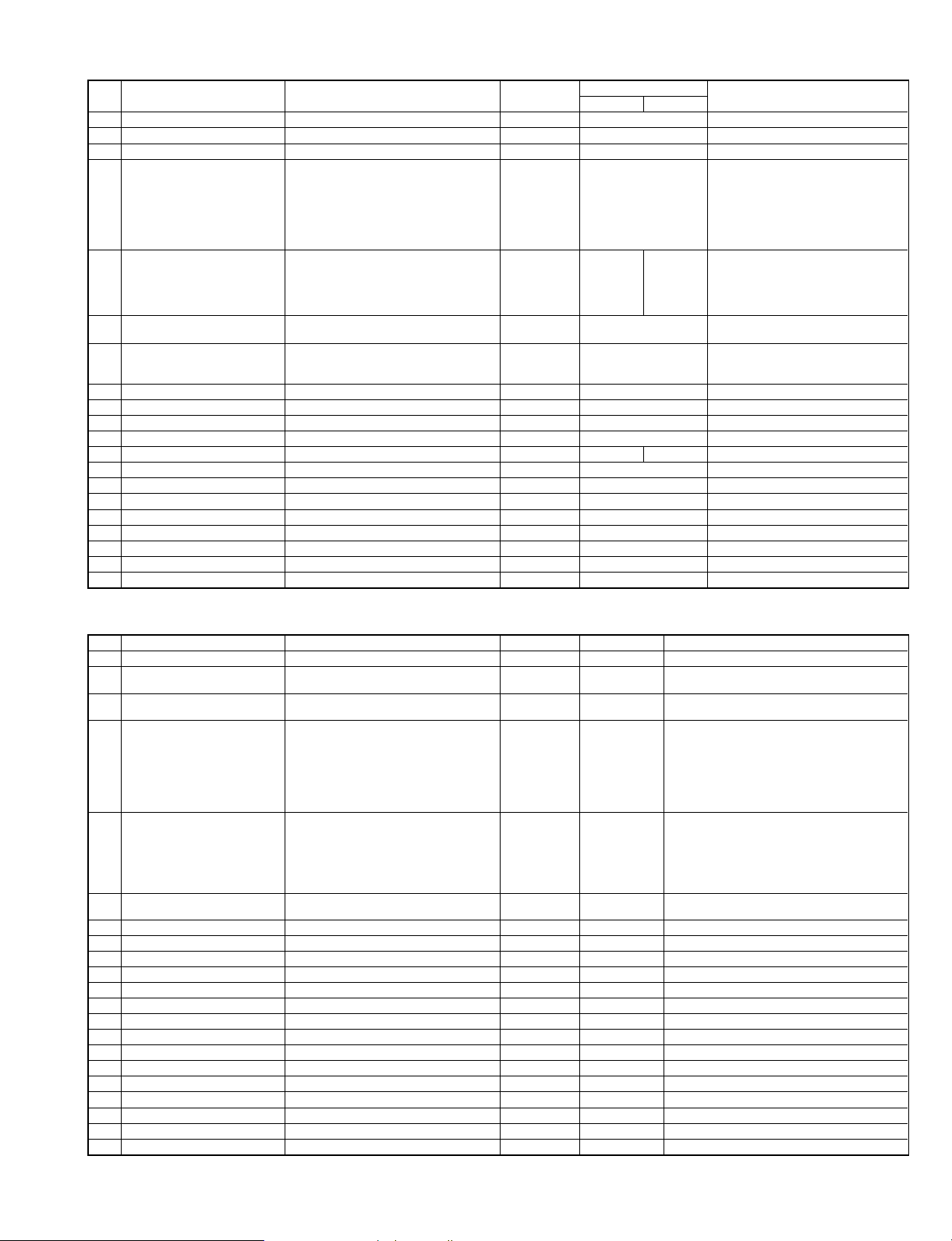
Warm up time Less than 65 sec
Pre-heat yes/no Yes
Jam recovery
time
About 10sec (Leaving the
machine for 60 sec after
opening the door, standard
condition, polygon stop.)
AR-405/407
Less than
75 sec
AR-501/
505/507
About
150 sec
About
30 sec
7. Copy magnification ratio
AR-250/280/281/285/
286/287/335/336/337
25, 50, 70, 81, 86, 100,
AB
Series
Inch
Series
Fixed magnification ratio
Zoom width 25 ~ 800% 25 ~ 400%
Independent
magnification width
115, 122, 141, 200, 400,
800%
5R + 6E
25, 50, 64, 77, 95, 100,
121, 129, 141, 200, 400,
800%
5R + 6E
25 ~ 800% for
horizontal/vertical
(25 ~ 800%
(high fidelity copy))
AR-405/407/
501/505/507
25, 50, 70, 81, 86, 100,
115, 122, 141, 200,
400%
25, 50, 64, 77, 95, 100,
121, 129, 141, 200,
400%
25 ~ 400% for
horizontal/vertical
8. Exposure
Exposure mode Auto, character, character/photo, photo
Manual steps 9 steps
Resolution
Gradation
Toner save mode
Read 400 dpi
Write 600 dpi
Read 256 gradations
Write 2 gradations (Default)
Set with the key operator program.
(In U.K., it is treated by a serviceman.)
9. Print area
A. Max. print area
Max. area
AB Series 416 ´ 293 mm
Inch Series 428 ´ 275 mm
B. Loss width
AR-501
AR-505
Void area
Image Loss Less than 5 mm
AR-507
Other
models
Lead edge 4 mm or less, rear edge 4 mm
or less, FR total 5 mm or less
Lead edge 3 mm or less, rear edge 4 mm
or less, FR total 5 mm or less
10. Paper exit
A. Paper exit form
AR-280/285/335
Paper exit form 2-tray paper exit 1-tray paper exit
AR-250/281/286/287/336/
337/405/407/501/505/507
2 – 3 7/13/2000
Page 16
B. Paper exit section
AR-250/281/
286/287/336/
337/405/407
AR-501/
505/507
Face up &
Face down
Paper exit tray
capacity
Paper exit
surface
(Face up/Face
down)
AR-280/
285/335
Upper Tray 250 sheets
Lower Tray 100 sheets —
Upper Tray Face up
Lower Tray Face up —
C. Paper size
Upper
Tray
Lower
Tray
AB Series A3 ~ A6R
Inch Series 11 ´ 17 ~ 8.5 ´ 5.5
AB Series A3 ~ A5
Inch Series 11 ´ 17 ~ 8.5 ´ 5.5
Duplex pass section : 56 ~ 105g/m
Size Paper Weight
50 ~ 128g/m
176g/m
50 ~ 105g/m
2
2
2
, 200g/m
2
,
11. Duplex module (AR-285/286/287/335/
336/337/405/407/501/505/507)
A. Auto duplex unit
AR-285/286/287/335/336/
337/405/407/501/505/507
Standard
Auto Duplex Unit
AR-250/280/281
Option
(AR-DU1)
B. Paper size
AB Series A3, B4, A4, A4R, B5, B5R, A5
Paper size
Paper Weight
Inch Series
11 ´ 17, 8.5 ´ 14, 8.5 ´ 13, 8.5 ´ 11,
8.5 ´ 11R, 7.25 ´ 10.5R
56 ~ 105g/m
2
(Same as the paper feed
section of the main body)
C. Capacity
Capacity 1 Sheet (Single Pass Method)
12. Shipping form
A. Packing form
Body Body/accessories
B. Paper size
First Tray
Second Tray
AB Series A3
Inch Series 11 ´ 17
AB Series A3
Inch Series 11 ´ 17
13. Additional functions
A. Main body functions
APS
AMS AMS by flow scan with DF is not allowed.
Auto tray switching
1 scan multi copy
Rotation copy
Pre-heat Conditions are set with the key operation.
Auto shut off Conditions are set with the key operation.
Message display
Key operator program
Communication
Process control
Coin vendor Only the connector is provided on the PWB.
E-mail Status/E-mail Alerts
(AR-287/337/407/507)
B. Copy function
AR-250/280/281/285/286/335/336/405/501/505
AR-250/280/281/
285/286/335/336
Job call/
registration
Dept. control
Binding margin
Edge erase AB series: 10mm, Inch series: 1/2" with adjustment
Center erase
1-set, 2-copy
2
Independent
zooming
White/black
reversion
Cover paper Cover/back cover/cover and back cover
OHP insert paper
Centering
Multi shot (Nin1) Paper feed size is up to A4.
Repeat copy
Date print Time setting by the key operation.
Stamp function
Middle binding HD is required for AR-250.
Page print HD is required for AR-250.
Max. 50 dept. Max. 500 dept.
Shift width AB series: 10mm, Inch series: 1/2" with
adjustment (Binding direction selectable)
25 ~ 800% for
vertical/horizontal
All surface only (only in the manual mode)
Insert paper copy Yes/No
selectable
AR-287/337/407/507
AR-287/337 AR-407 AR-507
Job call/ registration 9
Dept. control
Binding margin
Edge erase AB series: 10mm, Inch series: 1/2" with adjustment
Center erase
1-set, 2-copy
Independent zooming
White/black reversion All surface only (only in the manual mode)
Cover paper Cover/back cover/cover and back cover
OHP insert paper
Centering
Multi shot (Nin1)
Repeat copy Combination with AMS allowed
Date print Time setting by the key operation.
Stamp function
Middle binding
Page print
Confidential print
Security function Security ROM is installed. (AR-FR1/FR2/FR3)
Tandem print
(copy/print)
Network scanner When the scanner expansion kit is installed
Large quantity
document mode
*1: 60 sheets for sizes greater than A4 with print data
Shift width AB series: 10mm, Inch series: 1/2" with
25 to 800% for
vertical/horizontal
Insert paper copy Yes/No
When the tandem connection cable is connected
AR-405 AR-501/505
9
(Only the copy function is controlled.)
25 ~ 400% for vertical/horizontal
Only 1 face-up paper exit is
possible
Max. 50 dept. Max. 500 dept.
(Copy/Print/Tandem)
adjustment (Binding direction selectable)
25 to 400% for vertical/horizontal
selectable
(AR-287 invalid)
Documents of 120 sheets *1
Only 1 face-up paper
exit is possible
7/13/2000 2 – 4
Page 17

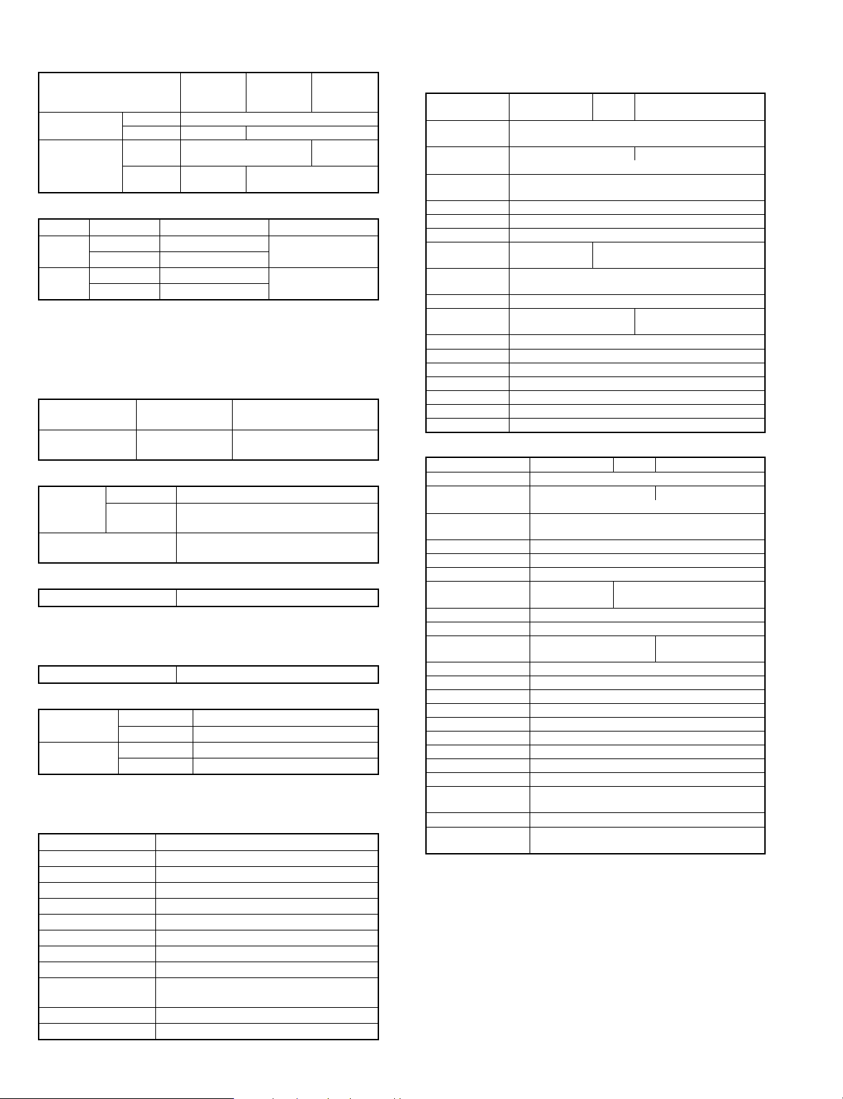
14. Options
Document
feeder
Paper
feed
Duplex
module
Finishing
AR-285
AR-250 AR-280
SPF Option Standard — — —
RADF Option — Standard Standard —
RSPF ————Standard
1 tray desk
(AR-DE1)
Large capacity
tray (AR-LC1)
Tray module
(AR-CS1)
Desk (AR-DD1) Option Option Option Option Option
Auto duplex
module
(AR-DU1)
Dual tray
output unit
(AR-TR1)
Finisher
(AR-FN1)
Finisher
(AR-FN2)
FN3 Option — — — Option
Option Option Option Option
Option Option Option Option
Option Option Option Option Option
Option Option Standard Standard Standard
Option Standard Standard Option —
Option Option Option Option —
Option — — Option —
AR-286
AR-287
AR-335
AR-336
AR-337
AR-405
AR-407
AR-501
AR-505
AR-507
Option
(AR-DE7)
Option
(AR-LC1N)
15. Other specifications
Photoconductor kind OPC drum
Photoconductor dia. 65 f
Process cleaning Blade
Exposure lamp No-electrode xenon lamp
Developing system Dry, 2-component magnetic brush
development
Charging system DC negative scorotron (saw tooth electrode)
Transfer system DC positive control
Separation system AC corotron/DC bias separation pawl
Fusing system Heat roller
Fusing cleaning Yes (AR-501/505/507 only)
(AR-287/337/407 only)
AC corotron/DC bias separation pawl/
Separation lamp (AR-501/505 only)
Photo discharge/AC corotron/
DC bias separation pawl (AR-507 only)
16. Outlook
W x D x H (mm)
AR-250 600 ´ 695 ´ 658 1292 ´ 630 About 81 kg
AR-280 600 ´ 695 ´ 698 1292 ´ 695 About 89 kg
AR-281 600 ´ 695 ´ 735 1292 ´ 695 About 87 kg
AR-285/335 600 ´ 695 ´ 750 1292 ´ 695 About 98 kg
AR-286/336 600 ´ 695 ´ 718 1292 ´ 695 About 101 kg
AR-287/337 600 ´ 695 ´ 750 1292 ´ 695 Approx 98 kg
AR-405 600 ´ 700 ´ 750 1292 ´ 700 About 98 kg
AR-407 600 ´ 700 ´ 750 1292 ´ 700 Approx 98 kg
AR-501/505 600 ´ 700 ´ 773 1292 ´ 700 About 102 kg
AR-507 600 ´ 700 ´ 773 1292 ´ 700 Approx 102 kg
Machine
occupying
dimensions
Weight
17. Power supply
Voltage 100 V, 110 V, 120 V, 127 V, 220-230 V, 240 V
Frequency 50/60 Hz Common
18. Power consumption
Max. power
consumption
AR-280/
285/335
Less than
1440 W
AR-250/281/
286/287/336/
337/405/407
Less than
1440 W
AR-501/
505/507
Less than
1590 W
19. Environmental measures
A. EnergyStar
AR-250 AR-280/285
Low power mode (Pre-heat mode)
Recovery time Less than 30 sec
Power
Sleep mode
(Power save mode)
consumption
Shift time Max. 240 min (Default 60 min)
Less than
101.25 W
Less than
15 W
Less than
112.8 W
Less than
15 W
AR-281/
286/287
Less than
112.8 W
AR-335 AR-336/337 AR-405/407
Less than
132.05 W
Less than
132.05 W
Less than
159 W
AR-501/
505/507
Less than
197.5 W
Less than
1 min
Less than
15 W
Less than
15 W
Less than
15 W
Less than
15 W
Less than
20 W
Max. 240 min
(Default
90 min)
2 – 5 7/13/2000
Page 18

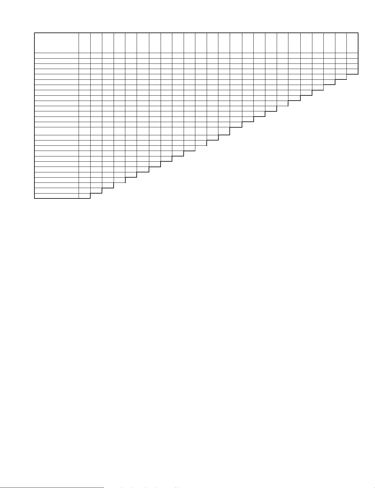
20. Combination of functions
AR-280/285/335
Inde-
AMS Water
pendent
zooming
S ® S
S (Even number) ® D
S (Odd number) ® D (DF only)
S ® D (Auto)
D ® D (DF only)
D ® S (DF only)
Staple sort
Sort
Group
Offset
Duplex copy direction switch
Hi-Fi copy (*)
Cover insertion (DF only)
OHP insert paper
Multi shot (DF only)
Repeat
Middle binding
1-set 2-copy (Document table only)
Binding margin
Edge erase
Centering
Black-white reversion
Date print
Page print
Stamp
Water mark
AMS
❍❍❍❍❍❍❍❍❍❍❍▲❍❍❍❍❍✕❍❍❍❍
❍❍❍❍❍❍❍❍❍❍❍▲❍❍✕❍✕❍❍❍❍❍
❍❍❍❍❍❍❍❍❍❍✕▲❍❍✕❍✕❍❍❍❍❍
❍❍❍❍❍❍❍❍❍❍❍▲❍❍✕❍✕❍❍❍❍❍
❍❍❍❍❍❍❍❍❍❍✕▲❍❍✕❍✕ ✕❍❍❍❍
❍❍❍❍❍❍❍❍❍❍✕▲❍❍❍❍❍✕❍❍❍❍
❍❍❍❍❍❍❍❍❍❍❍✕❍❍✕❍✕❍❍✕ ✕
❍❍❍❍❍❍❍❍❍❍❍❍❍❍D ❍ D ❍❍✕
❍❍❍❍❍❍❍❍❍❍❍❍❍❍D ❍❍❍❍
❍❍❍❍❍❍❍❍❍❍❍❍❍❍❍❍❍❍
❍❍❍❍❍❍❍❍❍❍✕❍✕✕✕❍✕
❍❍✕✕✕✕✕✕❍❍❍✕✕✕❍❍
❍❍❍❍❍❍✕❍❍❍✕✕✕✕✕
❍❍❍❍❍❍✕❍❍❍❍✕✕✕
✕✕❍❍❍❍✕❍❍❍✕✕✕
❍✕❍❍❍❍❍❍❍❍✕✕
✕❍❍❍❍❍✕❍❍❍✕
❍❍❍❍❍❍✕❍❍❍
❍❍❍❍❍❍❍❍❍
❍❍❍❍❍❍❍❍
❍❍❍❍❍❍❍
❍❍✕❍❍❍
❍❍❍❍❍
❍❍❍❍
❍❍✕
❍❍
❍
▲ Follows the setting on the middle binding display.
D Only one set of copies available.
* Combination with SPF mode is inhibited.
AR-250/281/286/287/336/337/405/407
AMS Water
Independent
zooming
S ® S
S ® D (Auto)
D ® D (DF only)
D ® S (DF only)
Staple sort
Sort
Group
Offset
Duplex copy direction switch
Cover insertion (DF only)
OHP insert paper
Multi shot (DF only)
Repeat
Middle binding
1-set 2-copy (Document table only)
Binding margin
Edge erase
Centering
Black-white reversion
Date print
Page print
Stamp
Water mark
AMS
▲ Follows the setting on the middle binding display.
D Only one set of copies available.
❍❍❍❍❍❍❍❍❍❍❍▲❍❍❍❍✕❍❍❍❍
❍❍❍❍❍❍❍❍❍❍❍▲❍❍✕❍❍❍❍❍❍
❍❍❍❍❍❍❍❍❍❍✕▲❍❍✕❍✕❍❍❍❍
❍❍❍❍❍❍❍❍❍❍✕▲❍❍❍❍✕❍❍❍❍
❍❍❍❍❍❍❍❍❍❍❍✕❍❍✕❍❍❍✕✕
❍❍❍❍❍❍❍❍❍❍❍❍❍❍D ❍❍❍✕
❍❍❍❍❍❍❍❍❍❍❍❍❍❍D ❍❍❍
❍❍❍❍❍❍❍❍❍❍❍❍❍❍❍❍❍
❍❍❍❍❍❍❍❍❍❍✕❍✕✕✕❍
❍❍❍❍❍❍✕❍❍❍✕✕✕✕✕
❍❍❍❍❍❍✕❍❍❍❍✕✕✕
✕✕❍❍❍❍✕❍❍❍✕ ✕✕
❍✕❍❍❍❍❍❍❍❍✕✕
✕❍❍❍❍❍✕❍❍❍✕
❍❍❍❍❍❍✕❍❍❍
❍❍❍❍❍❍❍❍❍
❍❍❍❍❍❍❍❍
❍❍❍❍❍❍❍
❍❍ ✕❍❍ ❍
❍❍❍❍❍
❍❍❍❍
❍❍ ✕
❍❍
❍
mark
mark
Stamp Page
print
Stamp Page
print
Date
print
Date
print
Blackwhite
reversion
Blackwhite
reversion
Centering
Centering
Edge
erase
Edge
erase
Binding
margin
Binding
margin
1-set
2copy
(Docu
-ment
table
only)
1-set 2copy
(Document
table
only)
Middle
binding
Middle
binding
Repeat
Repeat
Multi
shot
(DF
only)
Multi
shot
OHP
insert
paper
OHP
insert
paper
Cover
insertion
(DF
only)
Hi-Fi
copy
Cover
insertion
(DF
only)
Du-
Offset Group Sort Staple
plex
copy
direction
switch
Offset Group Sort Staple
Duplex
copy
direction
switch
sort
sort
7/13/2000 2 – 6
Page 19
AR-501/505/507
Inter-
Tan-
Inde-
S ® S
S ® D
D ® D (DF only)
D ® S (DF only)
Staple sort
Sort
Group
Offset
Duplex copy direction switch
Cover insertion (DF only)
OHP insert paper
Multi shot
Repeat
Middle binding
1-set 2-copy (Document table
only)
Binding margin
Edge erase
Center erase
Centering
Black-white reversion
Date print
Page print
Stamp
Water mark
AMS
Independent zooming
Tandem copy
ruption
dem
copy
*
AMS Water
pendent
*
zooming
❍❍❍❍❍❍❍❍❍❍❍❍❍❍▲❍❍❍❍ ✕❍❍❍❍
✕❍❍❍❍❍❍❍❍❍❍❍❍❍▲❍❍✕ ❍❍❍❍❍❍
✕❍❍❍❍❍❍❍❍❍❍❍❍✕▲❍❍✕ ❍✕❍❍❍❍
❍❍❍❍❍❍❍❍❍❍❍❍❍✕ ▲❍❍❍❍✕❍❍❍❍
✕❍❍❍❍❍❍❍❍❍❍❍❍❍ ✕❍❍✕ ❍❍✕✕✕
❍❍❍❍❍❍❍❍❍❍❍❍❍❍❍❍❍D ❍❍❍✕
❍✕❍❍❍❍❍❍❍❍❍❍❍❍❍❍❍D ❍❍❍
❍❍❍❍❍❍❍❍❍❍❍❍❍❍❍❍❍✕ ❍❍
✕❍❍❍❍❍❍❍❍❍❍❍❍✕❍✕✕ ✕ ❍
✕❍❍❍❍❍❍❍✕❍❍❍❍ ✕✕✕✕✕
❍✕❍❍❍❍❍❍✕❍❍❍❍❍✕✕✕
✕❍✕❍❍❍❍❍✕✕❍❍❍✕✕✕
❍❍❍✕❍❍❍❍❍✕❍❍❍✕ ✕
❍❍✕❍❍❍❍❍✕✕❍❍❍✕
❍❍❍❍❍❍❍❍✕❍✕❍❍
❍❍❍❍❍❍❍❍❍❍❍❍
❍❍❍❍❍❍❍❍❍❍❍
❍❍❍❍❍❍❍❍❍❍
❍❍❍✕❍❍❍❍❍
❍❍❍❍✕❍❍❍
❍❍❍❍❍❍❍
❍❍❍❍❍❍
❍❍❍❍✕
❍❍❍❍
❍❍❍
❍❍
✕
mark
Stamp Page
print
Date
print
Blackwhite
reversion
▲ Follows the setting on the middle binding display.
D Only one set of copies available.
When making an interruption, the number of documents is limited.
Single copy: Max. 20 sheets (A3/B4 document: 10sheets)
Duplex copy: Max. 10 sheets (A3/B4 document: 5 sheets)
* This function is valid in the AR-505 only.
Centering
Center
erase
Edge
erase
Binding
margin
1-set
2-copy
(Document
table
only)
Middle
binding
Repeat
Multi
shot
OHP
insert
paper
Cover
insertion
(DF
only)
Du-
Offset Group Sort Stapplex
copy
direction
switch
le sort
2 – 7 7/13/2000
Page 20
[3] CONSUMABLE PARTS
1. Consumable Parts List
A. USA
AR-250/280/281/285/286/287/335/336/337
No. ITEM CONTENTS LIFE
1 Drum OPC Drum ´1 160K AR-330DR AR-336DR
2 Developer (Black) Developer (800g) ´10 80K (´10)
3 Toner (Black) Toner Cartridge (700g) ´10 17.5K (´10)
Upper Heat Roller
4
Kit
Lower Heat Roller
5
Kit
80K Maintenance
6
Kit
7 Cleaner Blade Cleaner Blade ´10 80K (´10) AR-330CB AR-330CB= (AR-330BL) ´10
8 Staple Cartridge Staple Cartridge (SF-SC11) ´3 5K staples ´3 SF-SC11
9 Staple Cartridge Staple Cartridge (SF-SC12) ´3 5K staples ´3 SF-LS12
9 Upper Heat Roller Upper Heat Roller ´1 160K AR-330HU
Fusing Separation
10
Pawl (upper)
11 Heat Roller Gear Heat Roller Gear ´10 160K (´10) SF-216HG SF216HG= (SF216JG) ´10
12 Lower Heat Roller Lower Heat Roller ´1 160K AR-330HR AR-505HR
Fusing Separation
13
Pawl (lower)
Drum Separation
14
Pawl
15 Screen Grid Screen Grid ´10 80K (´10) AR-330SU AR-330SU= (AR-330TU) ´10
16 Charging Plate Charging Plate ´10 80K (´10) AR-330PU AR-330PU= (AR-330NU) ´10
Waste Toner
17
Bottle
18 Busing Busing ´2 ´10 160K (´10) SF-240BU SF-240BU= (SF-240DU) ´10
19 Ozone Filter Ozone Filter ´10 80K (´10) AR-330FL AR-330FL= (AR-330JL) ´10
20 Copy Lamp Copy Lamp ´10 AR-330CL AR-330CL= (AR-330DL) ´10
21 MC Unit MC Unit ´10 AR-330MC AR-330MC= (AR-330NC) ´10
Upper Heat Roller
Fusing Separation Pawl (upper)
Heat Roller Gear
Lower Heat Roller
Fusing Separation Pawl (lower)
Cleaner Blade
Charging Plate Unit
Drum Separation Unit
Fusing Separation Pawl (upper) ´4 ´10 80K (´10) SF-216UP
Fusing Separation Pawl (lower) ´2 ´10 80K (´10) SF-240LP
Drum Separation Pawl ´2 ´10 80K (´10) SF-240DP
Waste Toner Bottle ´1 AR-330TB
´1
´4
´1
´1
´2
´1
´1
´1
160K AR-330UH
160K AR-330LH AR-505LH
80K AR-330KA1 AR-400KA
AR-280/285/
AR-330MD
(AR330ND)
AR-330MT
(AR-330NT)
: AR-280/285/335 only
Note: Maintenance parts other than mentioned above must be ordered through the parts department using the proper part number.
335
MODEL NAME
AR-250/281/
286/336
AR-336MD
(AR-336ND)
AR-400MT
(AR-400NT)
AR-287/337
REMARKS
AR-330MD = (AR-330ND) ´ 10
AR-336MD = (AR-336ND) ´ 10
AR-330MT = (AR-330NT) ´ 10
AR-400MT = (AR-400NT) ´ 10
Replacement of fusing separation
pawl for every 90 K should be done
using those supplied separately.
Replacement of fusing separation
pawl for every 90 K should be done
using those supplied separately.
Cartridge for AR-FN1
Common with S55,S55 N
Cartridge for AR-FN2
Common with S54
SF-LS12= (SF-SC12) ´3
SF216UP=SF-216TP
(incl.4 pawls) ´10
SF240LP=SF-240MP
(incl.2 pawls) ´10
SF240DP=SF-240EP
(incl.2 pawls) ´10
7/13/2000 3 – 1
Page 21
AR-405/407
No. ITEM CONTENTS LIFE
1 Drum OPC Drum ´1 180K AR-400DR
2 Developer (Black) Developer (800g) ´10 90K (´10) AR-400MD AR-400MD = (AR-400ND) ´ 10
3 Toner (Black) Toner Cartridge (700g) ´10 22K (´1) AR-400MT AR-400MT = (AR-400NT) ´ 10
4 Upper Heat Roller Kit
5 Lower Heat Roller Kit
6 90K Maintenance Kit
7 Cleaner Blade Cleaner Blade ´10 90K (´10) AR-330CB AR-330CB= (AR-330BL) ´10
8 Staple Cartridge Staple Cartridge (SF-SC11) ´3 5K staples ´3 SF-SC11
9 Staple Cartridge Staple Cartridge (SF-SC12) ´3 5K staples ´3 SF-LS12
9 Upper Heat Roller Upper Heat Roller ´1 180K AR-330HU
10 Fusing Separation Pawl (upper) Fusing Separation Pawl (upper) ´4 ´10 90K (´10) SF-216UP SF216UP=SF-216TP (incl.4 pawls) ´10
11 Heat Roller Gear Heat Roller Gear ´10 180K (´10) SF-216HG SF216HG= (SF216JG) ´10
12 Lower Heat Roller Lower Heat Roller ´1 180K AR-330HR AR-505HR
13 Fusing Separation Pawl (lower) Fusing Separation Pawl (lower) ´2 ´10 90K (´10) SF-240LP SF240LP=SF-240MP (incl.2 pawls) ´10
14 Drum Separation Pawl Drum Separation Pawl ´2 ´10 90K (´10) SF-240DP SF240DP=SF-240EP (incl.2 pawls) ´10
15 Screen Grid Screen Grid ´10 90K (´10) AR-330SU AR-330SU= (AR-330TU) ´10
16 Charging Plate Charging Plate ´10 90K (´10) AR-330PU AR-330PU= (AR-330NU) ´10
17 Waste Toner Bottle Waste Toner Bottle ´1 AR-330TB
18 Busing Busing ´2 ´10 180K (´10) SF-240BU SF-240BU= (SF-240DU) ´10
19 Ozone Filter Ozone Filter ´10 90K (´10) AR-330FL AR-330FL= (AR-330JL) ´10
20 MC Unit MC Unit ´10 AR-330MC AR-330MC= (AR-330NC) ´10
Upper Heat Roller
Fusing Separation Pawl (upper)
Heat Roller Gear
Lower Heat Roller
Fusing Separation Pawl (lower)
Cleaner Blade
Charging Plate Unit
Drum Separation Unit
´1
´4
´1
´1
´2
´1
´1
´1
180K AR-330UH
180K AR-330LH AR-505LH
90K AR-400KA1
Note: Maintenance parts other than mentioned above must be ordered through the parts department using the proper part number.
MODEL NAME
AR-405 AR-407
REMARKS
Replacement of fusing separation pawl
for every 90 K should be done using
those supplied separately.
Replacement of fusing separation pawl
for every 90 K should be done using
those supplied separately.
Cartridge for AR-FN1
Common with S55,S55 N
Cartridge for AR-FN2
Common with S54
SF-LS12= (SF-SC12) ´3
AR-501/505/507
No. ITEM CONTENTS LIFE MODEL NAME REMARKS
1 Drum OPC Drum ´1 250K AR-500DR
2 Developer (Black) Developer (800g) ´10 250K (´10)
3 Toner (Black) Toner Cartridge (700g) ´10 25K (´10)
4 Upper Heat Roller Kit
5 Lower Heat Roller Kit
6 125K Maintenance Kit
7 Cleaner Blade Cleaner Blade ´10 125K (´10) AR-330CB AR-330CB= (AR-330BL) ´10
8 Curl Adjustment Roller Curl Adjustment Roller ´10 250K (´10) AR-505KR AR-505KR= (AR-505JR) ´10
9 Staple Cartridge Staple Cartridge (SF-SC11) ´3 5K staples ´3 SF-SC11
10 Upper Heat Roller Upper Heat Roller ´1 250K AR-505HU
11 Fusing Separation Pawl (upper) Fusing Separation Pawl (upper) ´4 ´10 125K (´10) AR-505UP AR-505UP=AR-505TP (incl.4 pawls) ´10
12 Heat Roller Gear Heat Roller Gear ´10 250K (´10) SF-216HG SF216HG= (SF216JG) ´10
13 Lower Heat Roller Lower Heat Roller ´1 250K AR-505HR
14 Fusing Separation Pawl (lower) Fusing Separation Pawl (lower) ´2 ´10 125K (´10) SF-240LP SF240LP=SF-240MP (incl.2 pawls) ´10
15 Drum Separation Pawl Drum Separation Pawl ´2 ´10 125K (´10) AR-505DP AR-505DP=AR-505EP (incl.2 pawls) ´10
16 Screen Grid Screen Grid ´10 125K (´10) AR-330SU AR-330SU= (AR-330TU) ´10
17 Charging Plate Charging Plate ´10 125K (´10) AR-330PU AR-330PU= (AR-330NU) ´10
18 Waste Toner Bottle Waste Toner Bottle ´1 AR-330TB
19 Busing Busing ´2 ´10 250K (´10) SF-240BU SF-240BU= (SF-240DU) ´10
20 Ozone Filter Ozone Filter ´10 125K (´10) AR-330FL AR-330FL= (AR-330JL) ´10
21 Ozone Filter 50 Ozone Filter 50 ´10 125K (´10) AR-505FL AR-505FL= (AR-505JL) ´10
22 MC Unit MC Unit ´10 AR-330MC AR-330MC= (AR-330NC) ´10
Upper Heat Roller
Fusing Separation Pawl (upper)
Heat Roller Gear
Lower Heat Roller
Fusing Separation Pawl (lower)
Cleaner Blade
Charging Plate Unit
Drum Separation Unit
Upper CL Roller Unit
´1
´4
´1
´1
´2
´1
´1
´1
´1
250K AR-505UH
250K AR-505LH
125K AR-505KA1
Note: Maintenance parts other than mentioned above must be ordered through the parts department using the proper part number.
AR-500MD
(AR500ND)
AR-500MT
(AR-500NT)
(AR-500ND) ´10 = AR-500MD
(AR-500NT) ´10 = AR-500MT
Cartridge for AR-FN1/FN1N/FN3
Common with S55,S55 N
3 – 2 7/13/2000
Page 22
B. Canada
AR-250/280/281/285/286/287/335/336/337
No. ITEM CONTENTS LIFE
1 Drum OPC Drum ´1 160K AR-330DR AR-336DR
2 Developer (Black) Developer (800g) ´10 80K (´10)
3 Toner (Black) Toner Cartridge (700g) ´10 17.5K (´10)
Cleaner Blade
Charging Plate Unit
4 80K PM Kit
5 160K PM Kit
6 Staple Cartridge Staple Cartridge (SF-SC11) ´3 5K staples ´3 SF-SC11
7 Staple Cartridge Staple Cartridge (SF-SC12) ´3 5K staples ´3 SF-LS12
8 Cleaner Blade Cleaner Blade ´10 80K (´10) AR-330CB AR-330CB= (AR-330BL) ´10
9 Upper Heat Roller Upper Heat Roller ´1 160K AR-330HU
Fusing Separation
10
Pawl (upper)
11 Heat Roller Gear Heat Roller Gear ´10 160K (´10) SF-216HG SF216HG= (SF216JG) ´10
12 Lower Heat Roller Lower Heat Roller ´1 160K AR-330HR AR-505HR
Fusing Separation
13
Pawl (lower)
14 Drum Separation Pawl Drum Separation Pawl ´2 ´10 80K (´10) SF-240DP
15 Screen Grid Screen Grid ´10 80K (´10) AR-330SU AR-330SU= (AR-330TU) ´10
16 Charging Plate Charging Plate ´10 80K (´10) AR-330PU AR-330PU= (AR-330NU) ´10
17 Waste Toner Bottle Waste Toner Bottle ´1 AR-330TB
18 Busing Busing ´2 ´10 160K (´10) SF-240BU SF-240BU= (SF-240DU) ´10
19 Ozone Filter Ozone Filter ´10 80K (´10) AR-330FL AR-330FL= (AR-330JL) ´10
20 Copy Lamp Copy Lamp ´10 AR-330CL AR-330CL= (AR-330DL) ´10
21 MC Unit MC Uni t ´10 AR-330MC AR-330MC= (AR-330NC) ´10
Waste Toner Bottle
Fusing Separation Pawl (upper)
Fusing Separation Pawl (lower)
Screen Grid
Drum Separation Unit
Upper Heat Roller
Lower Heat Roller
Toner Receiving Seal
DV Seal
Heat Roller Gear
Fusing Separation Pawl (upper) ´4 ´10 80K (´10) SF-216UP
Fusing Separation Pawl (lower) ´2 ´10 80K (´10) SF-240LP
´1
´1
´3
´4
´2
´1
´1
´1
´1
´1
´1
´1
80K AR-330KA AR-400KA
160K AR-330KB AR-337KB
AR-280/285/
AR-330MD
(AR330ND)
AR-330MT
(AR-330NT)
: AR-280/285/335 only
Note: Maintenance parts other than mentioned above must be ordered through the parts department using the proper part number.
335
MODEL NAME
AR-250/281/
286/336
AR-336MD
(AR-336ND)
AR-400MT
(AR-400NT)
AR-287/337
REMARKS
AR-330MD = (AR-330ND) ´ 10
AR-336MD = (AR-336ND) ´ 10
AR-330MT = (AR-330NT) ´ 10
AR-400MT = (AR-400NT) ´ 10
Cartridge for AR-FN1
Common with S55,S55 N
Cartridge for AR-FN2
Common with S54
SF-LS12= (SF-SC12) ´3
SF216UP=SF-216TP
(incl.4 pawls) ´10
SF240LP=SF-240MP
(incl.2 pawls) ´10
SF240DP=SF-240EP
(incl.2 pawls) ´10
7/13/2000 3 – 3
Page 23

AR-405/407
No. ITEM CONTENTS LIFE
1 Drum OPC Drum ´1 180K AR-400DR
2 Developer (Black) Developer (800g) ´10 80K (´10) AR-400MD AR-400MD = (AR-400ND) ´ 10
3 Toner (Black) Toner Cartridge (700g) ´10 22K (´1) AR-400MT AR-400MT = (AR-400NT) ´ 10
4 90K PM Kit
5 180K PM Kit
6 Staple Cartridge Staple Cartridge (SF-SC11) ´3 5K staples ´3 SF-SC11
7 Staple Cartridge Staple Cartridge (SF-SC12) ´3 5K staples ´3 SF-LS12
8 Cleaner Blade Cleaner Blade ´10 90K (´10) AR-330CB AR-330CB= (AR-330BL) ´10
9 Upper Heat Roller Upper Heat Roller ´1 180K AR-330HU
10 Fusing Separation Pawl (upper) Fusing Separation Pawl (upper) ´4 ´10 90K (´10) SF-216UP
11 Heat Roller Gear Heat Roller Gear ´10 180K (´10) SF-216HG SF216HG= (SF216JG) ´10
12 Lower Heat Roller Lower Heat Roller ´1 180K AR-330HR AR-505HR
13 Fusing Separation Pawl (lower) Fusing Separation Pawl (lower) ´2 ´10 90K (´10) SF-240LP
14 Drum Separation Pawl Drum Separation Pawl ´2 ´10 90K (´10) SF-240DP
15 Screen Grid Screen Grid ´10 90K (´10) AR-330SU AR-330SU= (AR-330TU) ´10
16 Charging Plate Charging Plate ´10 90K (´10) AR-330PU AR-330PU= (AR-330NU) ´10
17 Waste Toner Bottle Waste Toner Bottle ´1 AR-330TB
18 Busing Busing ´2 ´10 180K (´10) SF-240BU SF-240BU= (SF-240DU) ´10
19 Ozone Filter Ozone Filter ´10 90K (´10) AR-330FL AR-330FL= (AR-330JL) ´10
20 MC Unit MC Unit ´10 AR-330MC AR-330MC= (AR-330NC) ´10
Cleaner Blade
Charging Plate Unit
Waste Toner Bottle
Fusing Separation Pawl (upper)
Fusing Separation Pawl (lower)
Screen Grid
Drum Separation Unit
Upper Heat Roller
Lower Heat Roller
Toner Receiving Seal
DV Seal
Heat Roller Gear
´1
´1
´3
´4
´2
´1
´1
´1
´1
´1
´1
´1
90K AR-400KA
180K AR-330KB AR-337KB
Note: Maintenance parts other than mentioned above must be ordered through the parts department using the proper part number.
MODEL NAME
AR-405 AR-407
REMARKS
Cartridge for AR-FN1
Common with S55,S55 N
Cartridge for AR-FN2
Common with S54
SF-LS12= (SF-SC12) ´3
SF216UP=SF-216TP (incl.4
pawls) ´10
SF240LP=SF-240MP (incl.2
pawls) ´10
SF240DP=SF-240EP (incl.2
pawls) ´10
AR-505/507
No. ITEM CONTENTS LIFE
1 Drum OPC Drum ´1 250K AR-500DR
2 Developer (Black) Developer (800g) ´10 250K (´10)
3 Toner (Black) Toner Cartridge (700g) ´10 25K (´10)
Cleaner Blade
Charging Plate Unit
Waste Toner Bottle
4 125K PM Kit
5 250K PM Kit
6 Staple Cartridge Staple Cartridge (SF-SC11) ´3 5K staples ´3 SF-SC11
7 Cleaner Blade Cleaner Blade ´10 125K (´10) AR-330CB AR-330CB= (AR-330BL) ´10
8 Upper Heat Roller Upper Heat Roller ´1 250K AR-505HU
9 Fusing Separation Pawl (upper) Fusing Separation Pawl (upper) ´4 ´10 125K (´10) AR-505UP AR-505UP=AR-505TP (incl.4 pawls) ´10
10 Heat Roller Gear Heat Roller Gear ´10 250K (´10) SF-216HG SF216HG= (SF216JG) ´10
11 Lower Heat Roller Lower Heat Roller ´1 250K AR-505HR
12 Fusing Separation Pawl (lower) Fusing Separation Pawl (lower) ´2 ´10 125K (´10) SF-240LP SF240LP=SF-240MP (incl.2 pawls) ´10
13 Drum Separation Pawl Drum Separation Pawl ´2 ´10 125K (´10) AR-505DP AR-505DP=AR-505EP (incl.2 pawls) ´10
14 Screen Grid Screen Grid ´10 125K (´10) AR-330SU AR-330SU= (AR-330TU) ´10
15 Charging Plate Charging Plate ´10 125K (´10) AR-330PU AR-330PU= (AR-330NU) ´10
16 Waste Toner Bottle Waste Toner Bottle ´1 AR-330TB
17 Busing Busing ´2 ´10 250K (´10) SF-240BU SF-240BU= (SF-240DU) ´10
18 Ozone Filter Ozone Filter ´10 125K (´10) AR-330FL AR-330FL= (AR-330JL) ´10
19 Ozone Filter 50 Ozone Filter 50 ´10 125K (´10) AR-505FL AR-505FL= (AR-505JL) ´10
20 MC Unit MC Unit ´10 AR-330MC AR-330MC= (AR-330NC) ´10
21 Curl Adjustment Roller Curl Adjustment Roller ´10 250K (´10) AR-505KR AR-505KR= (AR-505JR) ´10
Fusing Separation Pawl (upper)
Fusing Separation Pawl (lower)
Screen Grid
Drum Separation Unit
Cleaning Roller
Upper CL Roller Unit
Upper Heat Roller
Lower Heat Roller
Toner Receiving Seal
DV Seal
Heat Roller Gear
Curl Adjustment Roller
´1
´1
´3
´4
´2
´1
´1
´1
´1
´1
´1
´1
´1
´1
´1
125K AR-505KA
250K AR-505KB
Note: Maintenance parts other than mentioned above must be ordered through the parts department using the proper part number.
MODEL
NAME
AR-500MD
(AR500ND)
AR-500MT
(AR-500NT)
REMARKS
(AR-500ND) ´10 = AR-500MD
(AR-500NT) ´10 = AR-500MT
Cartridge for AR-FN1/FN1N/FN3
Common with S55,S55 N
3 – 4 7/13/2000
Page 24
C. Europe / U.K. / Australia / New Zealand
AR-250/280/281/285/286/287/335/336/337
No. ITEM CONTENTS LIFE
1 Drum OPC Drum ´1 160K AR-330DM AR-331DM
2 Developer (Black) Developer (800g) ´10 80K (´10)
3 Toner (Black) Toner Cartridge (700g) ´10 17.5K (´10)
Cleaner Blade
Charging Plate Unit
4 80K PM Kit
5 160K PM Kit
6 Staple Cartridge Staple Cartridge (SF-SC11) ´3 5K staples ´3 SF-SC11
7 Staple Cartridge Staple Cartridge (SF-SC12) ´3 5K staples ´3 SF-LS12
8 Cleaner Blade Cleaner Blade ´10 80K (´10) AR-330CB AR-330CB= (AR-330BL) ´10
9 Upper Heat Roller Upper Heat Roller ´1 160K AR-330HU
Fusing Separation Pawl
10
(upper)
11 Heat Roller Gear Heat Roller Gear ´10 160K (´10) SF-216HG SF216HG= (SF216JG) ´10
12 Lower Heat Roller Lower Heat Roller ´1 160K AR-330HR AR-505HR
Fusing Separation Pawl
13
(upper)
14 Drum Separation Pawl Drum Separation Pawl ´2 ´10 80K (´10) SF-240DP
15 Screen Grid Screen Grid ´10 80K (´10) AR-330SU AR-330SU= (AR-330TU) ´10
16 Charging Plate Charging Plate ´10 80K (´10) AR-330PU AR-330PU= (AR-330NU) ´10
17 Waste Toner Bottle Waste Toner Bottle ´1 AR-330TB
18 Busing Busing ´2 ´10 160K (´10) SF-240BU SF-240BU= (SF-240DU) ´10
19 Ozone Filter Ozone Filter ´10 80K (´10) AR-330FL AR-330FL= (AR-330JL) ´10
20 Copy Lamp Copy Lamp ´10 AR-330CL AR-330CL= (AR-330DL) ´10
21 MC Unit MC Unit ´10 AR-330MC AR-330MC= (AR-330NC) ´10
Waste Toner Bottle
Fusing Separation Pawl (upper)
Fusing Separation Pawl (lower)
Screen Grid
Drum Separation Unit
Upper Heat Roller
Lower Heat Roller
Toner Receiving Seal
DV Seal
Heat Roller Gear
Fusing Separation Pawl (upper) ´4 ´10 80K (´10) SF-216UP
Fusing Separation Pawl (lower) ´2 ´10 80K (´10) SF-240LP
´1
´1
´3
´4
´2
´1
´1
´1
´1
´1
´1
´1
80K AR-330KA AR-400KA
160K AR-330KB AR-337KB
AR-280/285/
AR-330LD
(AR330DV)
AR-330LT
(AR-330T)
: AR-280/285/335 only
Note: Maintenance parts other than mentioned above must be ordered through the parts department using the proper part number.
335
MODEL NAME
AR-250/281/
286/336
AR-336LD
(AR-336DV)
AR-400LT
(AR-400T)
AR-287/337
REMARKS
AR-330LD = (AR-330DV) ´ 10
AR-336LD = (AR-336DV) ´ 10
AR-330LT = (AR-330T) ´ 10
AR-400LT = (AR-400T) ´ 10
Cartridge for AR-FN1
Common with S55,S55 N
Cartridge for AR-FN2
Common with S54
SF-LS12= (SF-SC12) ´3
SF216UP=SF-216TP
(incl.4 pawls) ´10
SF240LP=SF-240MP
(incl.2 pawls) ´10
SF240DP=SF-240EP
(incl.2 pawls) ´10
7/13/2000 3 – 5
Page 25
AR-405/407
No. ITEM CONTENTS LIFE
1 Drum OPC Drum ´1 180K AR-400DM
2 Developer (Black) Developer (800g) ´10 90K (´10) AR-400LD AR-400LD = (AR-400DV) ´ 10
3 Toner (Black) Toner Cartridge (700g) ´10 22K (´1) AR-400LT AR-400LT = (AR-400T) ´ 10
Cleaner Blade
Charging Plate Unit
4 90K PM Kit
5 180K PM Kit
6 Staple Cartridge Staple Cartridge (SF-SC11) ´3 5K staples ´3 SF-SC11
7 Staple Cartridge Staple Cartridge (SF-SC12) ´3 5K staples ´3 SF-LS12
8 Cleaner Blade Cleaner Blade ´10 90K (´10) AR-330CB AR-330CB= (AR-330BL) ´10
9 Upper Heat Roller Upper Heat Roller ´1 180K AR-400HU
10 Fusing Separation Pawl (upper) Fusing Separation Pawl (upper) ´4 ´10 90K (´10) SF-216UP SF216UP=SF-216TP (incl.4 pawls) ´10
11 Heat Roller Gear Heat Roller Gear ´10 180K (´10) SF-216HG SF216HG= (SF216JG) ´10
12 Lower Heat Roller Lower Heat Roller ´1 180K AR-330HR AR-505HR
13 Fusing Separation Pawl (upper) Fusing Separation Pawl (lower) ´2 ´10 90K (´10) SF-240LP SF240LP=SF-240MP (incl.2 pawls) ´10
14 Drum Separation Pawl Drum Separation Pawl ´2 ´10 90K (´10) SF-240DP SF240DP=SF-240EP (incl.2 pawls) ´10
15 Screen Grid Screen Grid ´10 90K (´10) AR-330SU AR-330SU= (AR-330TU) ´10
16 Charging Plate Charging Plate ´10 90K (´10) AR-330PU AR-330PU= (AR-330NU) ´10
17 Waste Toner Bottle Waste Toner Bottle ´1 AR-330TB
18 Busing Busing ´2 ´10 180K (´10) SF-240BU SF-240BU= (SF-240DU) ´10
19 Ozone Filter Ozone Filter ´10 90K (´10) AR-330FL AR-330FL= (AR-330JL) ´10
20 MC Unit MC Unit ´10 AR-330MC AR-330MC= (AR-330NC) ´10
Waste Toner Bottle
Fusing Separation Pawl (upper)
Fusing Separation Pawl (lower)
Screen Grid
Drum Separation Unit
Upper Heat Roller
Lower Heat Roller
Toner Receiving Seal
DV Seal
Heat Roller Gear
´1
´1
´3
´4
´2
´1
´1
´1
´1
´1
´1
´1
90K AR-400KA
180K AR-400KB AR-407KB
Note: Maintenance parts other than mentioned above must be ordered through the parts department using the proper part number.
MODEL NAME
AR-405 AR-407
REMARKS
Cartridge for AR-FN1
Common with S55,S55 N
Cartridge for AR-FN2
Common with S54
SF-LS12= (SF-SC12) ´3
AR-505/507
No. ITEM CONTENTS LIFE MODEL NAME REMARKS
1 Drum OPC Drum ´1 250K AR-500DM
2 Developer (Black) Developer (800g) ´10 250K (´10)
3 Toner (Black) Toner Cartridge (700g) ´10 25K (´10)
Cleaner Blade
Charging Plate Unit
Waste Toner Bottle
4 125K PM Kit
5 250K PM Kit
6 Staple Cartridge Staple Cartridge (SF-SC11) ´3 5K staples ´3 SF-SC11
7 Cleaner Blade Cleaner Blade ´10 125K (´10) AR-330CB AR-330CB= (AR-330BL) ´10
8 Upper Heat Roller Upper Heat Roller ´1 250K AR-505HU
9 Fusing Separation Pawl (upper) Fusing Separation Pawl (upper) ´4 ´10 125K (´10) AR-505UP AR-505UP=AR-505TP (incl.4 pawls) ´10
10 Heat Roller Gear Heat Roller Gear ´10 250K (´10) SF-216HG SF216HG= (SF216JG) ´10
11 Lower Heat Roller Lower Heat Roller ´1 250K AR-505HR
12 Fusing Separation Pawl (lower) Fusing Separation Pawl (lower) ´2 ´10 125K (´10) SF-240LP SF240LP=SF-240MP (incl.2 pawls) ´10
13 Drum Separation Pawl Drum Separation Pawl ´2 ´10 125K (´10) AR-505DP AR-505DP=AR-505EP (incl.2 pawls) ´10
14 Screen Grid Screen Grid ´10 125K (´10) AR-330SU AR-330SU= (AR-330TU) ´10
15 Charging Plate Charging Plate ´10 125K (´10) AR-330PU AR-330PU= (AR-330NU) ´10
16 Waste Toner Bottle Waste Toner Bottle ´1 AR-330TB
17 Busing Busing ´2 ´10 250K (´10) SF-240BU SF-240BU= (SF-240DU) ´10
18 Ozone Filter Ozone Filter ´10 125K (´10) AR-330FL AR-330FL= (AR-330JL) ´10
19 Ozone Filter 50 Ozone Filter 50 ´10 125K (´10) AR-505FL AR-505FL= (AR-505JL) ´10
20 MC Unit MC Unit ´10 AR-330MC AR-330MC= (AR-330NC) ´10
21 Curl Adjustment Roller Curl Adjustment Roller ´10 250K (´10) AR-505KR AR-505KR= (AR-505JR) ´10
Fusing Separation Pawl (upper)
Fusing Separation Pawl (lower)
Screen Grid
Drum Separation Unit
Cleaning Roller
Upper Heat Roller
Lower Heat Roller
Toner Receiving Seal
DV Seal
Heat Roller Gear
Curl Adjustment Roller
Upper CL Roller Unit
´1
´1
´3
´4
´2
´1
´1
´1
´1
´1
´1
´1
´1
´1
´1
125K AR-505KA
250K AR-505KB
Note: Maintenance parts other than mentioned above must be ordered through the parts department using the proper part number.
AR-500LD
(AR-500DV)
AR-500LT
(AR-500T)
(AR-500DV) ´10 = AR-500LD
(AR-500T) ´10 = AR-500LT
Cartridge for AR-FN1/FN1N/FN3
Common with S55,S55 N
3 – 6 7/13/2000
Page 26

D. Asia / Middle & South America
AR-250/280/281/285/286/287/335/336/337
No. ITEM CONTENTS LIFE
1 Drum OPC Drum ´1 160K AR-330DR AR-336DR
2 Developer (Black) Developer (800g) ´10 80K (´10)
3 Toner (Black) Toner Cartridge (700g) ´10 17.5K (´10)
Cleaner Blade
Charging Plate Unit
4 80K PM Kit
5 160K PM Kit
6 Staple Cartridge Staple Cartridge (SF-SC11) ´3 5K staples ´3 SF-SC11
7 Staple Cartridge Staple Cartridge (SF-SC12) ´3 5K staples ´3 SF-LS12
8 Cleaner Blade Cleaner Blade ´10 80K (´10) AR-330CB AR-330CB= (AR-330BL) ´10
9 Upper Heat Roller Upper Heat Roller ´1 160K AR-330HU
Fusing Separation Pawl
10
(upper)
11 Heat Roller Gear Heat Roller Gear ´10 160K (´10) SF-216HG SF216HG= (SF216JG) ´10
12 Lower Heat Roller Lower Heat Roller ´1 160K AR-330HR AR-505HR
Fusing Separation Pawl
13
(lower)
14 Drum Separation Pawl Drum Separation Pawl ´2 ´10 80K (´10) SF-240DP
15 Screen Grid Screen Grid ´10 80K (´10) AR-330SU AR-330SU= (AR-330TU) ´10
16 Charging Plate Charging Plate ´10 80K (´10) AR-330PU AR-330PU= (AR-330NU) ´10
17 Waste Toner Bottle Waste Toner Bottle ´1 AR-330TB
18 Busing Busing ´2 ´10 160K (´10) SF-240BU SF-240BU= (SF-240DU) ´10
19 Ozone Filter Ozone Filter ´10 80K (´10) AR-330FL AR-330FL= (AR-330JL) ´10
20 Copy Lamp Copy Lamp ´10 AR-330CL AR-330CL= (AR-330DL) ´10
21 MC Unit MC Unit ´10 AR-330MC AR-330MC= (AR-330NC) ´10
Waste Toner Bottle
Fusing Separation Pawl (upper)
Fusing Separation Pawl (lower)
Screen Grid
Drum Separation Unit
Upper Heat Roller
Lower Heat Roller
Toner Receiving Seal
DV Seal
Heat Roller Gear
Fusing Separation Pawl (upper) ´4 ´10 80K (´10) SF-216UP
Fusing Separation Pawl (lower) ´2 ´10 80K (´10) SF-240LP
´1
´1
´3
´4
´2
´1
´1
´1
´1
´1
´1
´1
80K AR-330KA
160K AR-330KB AR-337KB
AR-280/285/
AR-330CD
(AR330SD)
AR-330CT
(AR-330ST)
: AR-280/285/335 only
Note: Maintenance parts other than mentioned above must be ordered through the parts department using the proper part number.
335
MODEL NAME
AR-250/281/
286/336
AR-336CD
(AR-336SD)
AR-400CT
(AR-400ST)
AR-287/337
REMARKS
AR-330CD = (AR-330SD) ´ 10
AR-336CD = (AR-336SD) ´ 10
AR-330CT = (AR-330ST) ´ 10
AR-400CT = (AR-400ST) ´ 10
Cartridge for AR-FN1
Common with S55,S55 N
Cartridge for AR-FN2
Common with S54
SF-LS12= (SF-SC12) ´3
SF216UP=SF-216TP
(incl.4 pawls) ´10
SF240LP=SF-240MP
(incl.2 pawls) ´10
SF240DP=SF-240EP
(incl.2 pawls) ´10
7/13/2000 3 – 7
Page 27

AR-405/407
No. ITEM CONTENTS LIFE
1 Drum OPC Drum ´1 180K AR-400DM
2 Developer (Black) Developer (800g) ´10 90K (´10) AR-400CD AR-400CD = (AR-400SD) ´ 10
3 Toner (Black) Toner Cartridge (700g) ´10 22K (´1) AR-400CT AR-400CT = (AR-400ST) ´ 10
4 90K PM Kit
5 180K PM Kit
6 Staple Cartridge Staple Cartridge (SF-SC11) ´3 5K staples ´3 SF-SC11
7 Staple Cartridge Staple Cartridge (SF-SC12) ´3 5K staples ´3 SF-LS12
8 Cleaner Blade Cleaner Blade ´10 90K (´10) AR-330CB AR-330CB= (AR-330BL) ´10
9 Upper Heat Roller Upper Heat Roller ´1 180K AR-400HU
10 Fusing Separation Pawl (upper) Fusing Separation Pawl (upper) ´4 ´10 90K (´10) SF-216UP SF216UP=SF-216TP (incl.4 pawls) ´10
11 Heat Roller Gear Heat Roller Gear ´10 180K (´10) SF-216HG SF216HG= (SF216JG) ´10
12 Lower Heat Roller Lower Heat Roller ´1 180K AR-330HR AR-505HR
13 Fusing Separation Pawl (lower) Fusing Separation Pawl (lower) ´2 ´10 90K (´10) SF-240LP SF240LP=SF-240MP (incl.2 pawls) ´10
14 Drum Separation Pawl Drum Separation Pawl ´2 ´10 90K (´10) SF-240DP SF240DP=SF-240EP (incl.2 pawls) ´10
15 Screen Grid Screen Grid ´10 90K (´10) AR-330SU AR-330SU= (AR-330TU) ´10
16 Charging Plate Charging Plate ´10 90K (´10) AR-330PU AR-330PU= (AR-330NU) ´10
17 Waste Toner Bottle Waste Toner Bottle ´1 AR-330TB
18 Busing Busing ´2 ´10 180K (´10) SF-240BU SF-240BU= (SF-240DU) ´10
19 Ozone Filter Ozone Filter ´10 90K (´10) AR-330FL AR-330FL= (AR-330JL) ´10
20 MC Unit MC Unit ´10 AR-330MC AR-330MC= (AR-330NC) ´10
Cleaner Blade
Charging Plate Unit
Waste Toner Bottle
Fusing Separation Pawl (upper)
Fusing Separation Pawl (lower)
Screen Grid
Drum Separation Unit
Upper Heat Roller
Lower Heat Roller
Toner Receiving Seal
DV Seal
Heat Roller Gear
´1
´1
´3
´4
´2
´1
´1
´1
´1
´1
´1
´1
90K AR-400KA
180K AR-400KB AR-407KB
Note: Maintenance parts other than mentioned above must be ordered through the parts department using the proper part number.
MODEL NAME
AR-405 AR-407
REMARKS
Cartridge for AR-FN1
Common with S55,S55 N
Cartridge for AR-FN2
Common with S54
SF-LS12= (SF-SC12) ´3
AR-505/507
No. ITEM CONTENTS LIFE
1 Drum OPC Drum ´1 250K AR-500DR
2 Developer (Black) Developer (800g) ´10 250K (´10)
3 Toner (Black) Toner Cartridge (700g) ´10 25K (´10)
Cleaner Blade
Charging Plate Unit
Waste Toner Bottle
4 125K PM Kit
5 250K PM Kit
6 Staple Cartridge Staple Cartridge (SF-SC11) ´3 5K staples ´3 SF-SC11
7 Cleaner Blade Cleaner Blade ´10 125K (´10) AR-330CB AR-330CB= (AR-330BL) ´10
8 Upper Heat Roller Upper Heat Roller ´1 250K AR-505HU
9 Fusing Separation Pawl (upper) Fusing Separation Pawl (upper) ´4 ´10 125K (´10) AR-505UP AR-505UP=AR-505TP (incl.4 pawls) ´10
10 Heat Roller Gear Heat Roller Gear ´10 250K (´10) SF-216HG SF216HG= (SF216JG) ´10
11 Lower Heat Roller Lower Heat Roller ´1 250K AR-505HR
12 Fusing Separation Pawl (lower) Fusing Separation Pawl (lower) ´2 ´10 125K (´10) SF-240LP SF240LP=SF-240MP (incl.2 pawls) ´10
13 Drum Separation Pawl Drum Separation Pawl ´2 ´10 125K (´10) AR-505DP AR-505DP=AR-505EP (incl.2 pawls) ´10
14 Screen Grid Screen Grid ´10 125K (´10) AR-330SU AR-330SU= (AR-330TU) ´10
15 Charging Plate Charging Plate ´10 125K (´10) AR-330PU AR-330PU= (AR-330NU) ´10
16 Waste Toner Bottle Waste Toner Bottle ´1 AR-330TB
17 Busing Busing ´2 ´10 250K (´10) SF-240BU SF-240BU= (SF-240DU) ´10
18 Ozone Filter Ozone Filter ´10 125K (´10) AR-330FL AR-330FL= (AR-330JL) ´10
19 Ozone Filter 50 Ozone Filter 50 ´10 125K (´10) AR-505FL AR-505FL= (AR-505JL) ´10
20 MC Unit MC Unit ´10 AR-330MC AR-330MC= (AR-330NC) ´10
21 Curl Adjustment Roller Curl Adjustment Roller ´10 250K (´10) AR-505KR AR-505KR= (AR-505JR) ´10
Fusing Separation Pawl (upper)
Fusing Separation Pawl (lower)
Screen Grid
Drum Separation Unit
Cleaning Roller
Upper CL Roller Unit
Upper Heat Roller
Lower Heat Roller
Toner Receiving Seal
DV Seal
Heat Roller Gear
Curl Adjustment Roller
´1
´1
´3
´4
´2
´1
´1
´1
´1
´1
´1
´1
´1
´1
´1
125K AR-505KA
250K AR-505KB
Note: Maintenance parts other than mentioned above must be ordered through the parts department using the proper part number.
MODEL
NAME
AR-500CD
(AR500SD)
AR-500CT
(AR-500ST)
REMARKS
(AR-500SD) ´10 = AR-500CD
(AR-500ST) ´10 = AR-500CT
Cartridge for AR-FN1/FN1N/FN3
Common with S55,S55 N
3 – 8 7/13/2000
Page 28

E. Middle East / Africa
AR-250/280/281/285/286/287/335/336/337
No. ITEM CONTENTS LIFE
1 Drum OPC Drum ´1 160K AR-330DM AR-336DM
2 Developer (Black) Developer (800g) ´10 80K (´10)
3 Toner (Black) Toner Cartridge (700g) ´10 17.5K (´10)
Cleaner Blade
Charging Plate Unit
4 80K PM Kit
5 160K PM Kit
6 Staple Cartridge Staple Cartridge (SF-SC11) ´3 5K staples ´3 SF-SC11
7 Staple Cartridge Staple Cartridge (SF-SC12) ´3 5K staples ´3 SF-LS12
8 Cleaner Blade Cleaner Blade ´10 80K (´10) AR-330CB AR-330CB= (AR-330BL) ´10
9 Upper Heat Roller Upper Heat Roller ´1 160K AR-330HU
Fusing Separation Pawl
10
(upper)
11 Heat Roller Gear Heat Roller Gear ´10 160K (´10) SF-216HG SF216HG= (SF216JG) ´10
12 Lower Heat Roller Lower Heat Roller ´1 160K AR-330HR AR-505HR
Fusing Separation Pawl
13
(lower)
14 Drum Separation Pawl Drum Separation Pawl ´2 ´10 80K (´10) SF-240DP
15 Screen Grid Screen Grid ´10 80K (´10) AR-330SU AR-330SU= (AR-330TU) ´10
16 Charging Plate Charging Plate ´10 80K (´10) AR-330PU AR-330PU= (AR-330NU) ´10
17 Waste Toner Bottle Waste Toner Bottle ´1 AR-330TB
18 Busing Busing ´2 ´10 160K (´10) SF-240BU SF-240BU= (SF-240DU) ´10
19 Ozone Filter Ozone Filter ´10 80K (´10) AR-330FL AR-330FL= (AR-330JL) ´10
20 Copy Lamp Copy Lamp ´10 AR-330CL AR-330CL= (AR-330DL) ´10
21 MC Unit MC Unit ´10 AR-330MC AR-330MC= (AR-330NC) ´10
Waste Toner Bottle
Fusing Separation Pawl (upper)
Fusing Separation Pawl (lower)
Screen Grid
Drum Separation Unit
Upper Heat Roller
Lower Heat Roller
Toner Receiving Seal
DV Seal
Heat Roller Gear
Fusing Separation Pawl (upper) ´4 ´10 80K (´10) SF-216UP
Fusing Separation Pawl (lower) ´2 ´10 80K (´10) SF-240LP
´1
´1
´3
´4
´2
´1
´1
´1
´1
´1
´1
´1
80K AR-330KA
160K AR-330KB AR-337KB
AR-280/285/
AR-330LD
(AR330DV)
AR-330LT
(AR-330T)
: AR-280/285/335 only
Note: Maintenance parts other than mentioned above must be ordered through the parts department using the proper part number.
335
MODEL NAME
AR-250/281/
286/336
AR-336LD
(AR-336DV)
AR-400LT
(AR-400T)
AR-287/337
REMARKS
AR-330LD = (AR-330DV) ´ 10
AR-336LD = (AR-336DV) ´ 10
AR-330LT = (AR-330T) ´ 10
AR-400LT = (AR-400T) ´ 10
Cartridge for AR-FN1
Common with S55,S55 N
Cartridge for AR-FN2
Common with S54
SF-LS12= (SF-SC12) ´3
SF216UP=SF-216TP
(incl.4 pawls) ´10
SF240LP=SF-240MP
(incl.2 pawls) ´10
SF240DP=SF-240EP
(incl.2 pawls) ´10
7/13/2000 3 – 9
Page 29
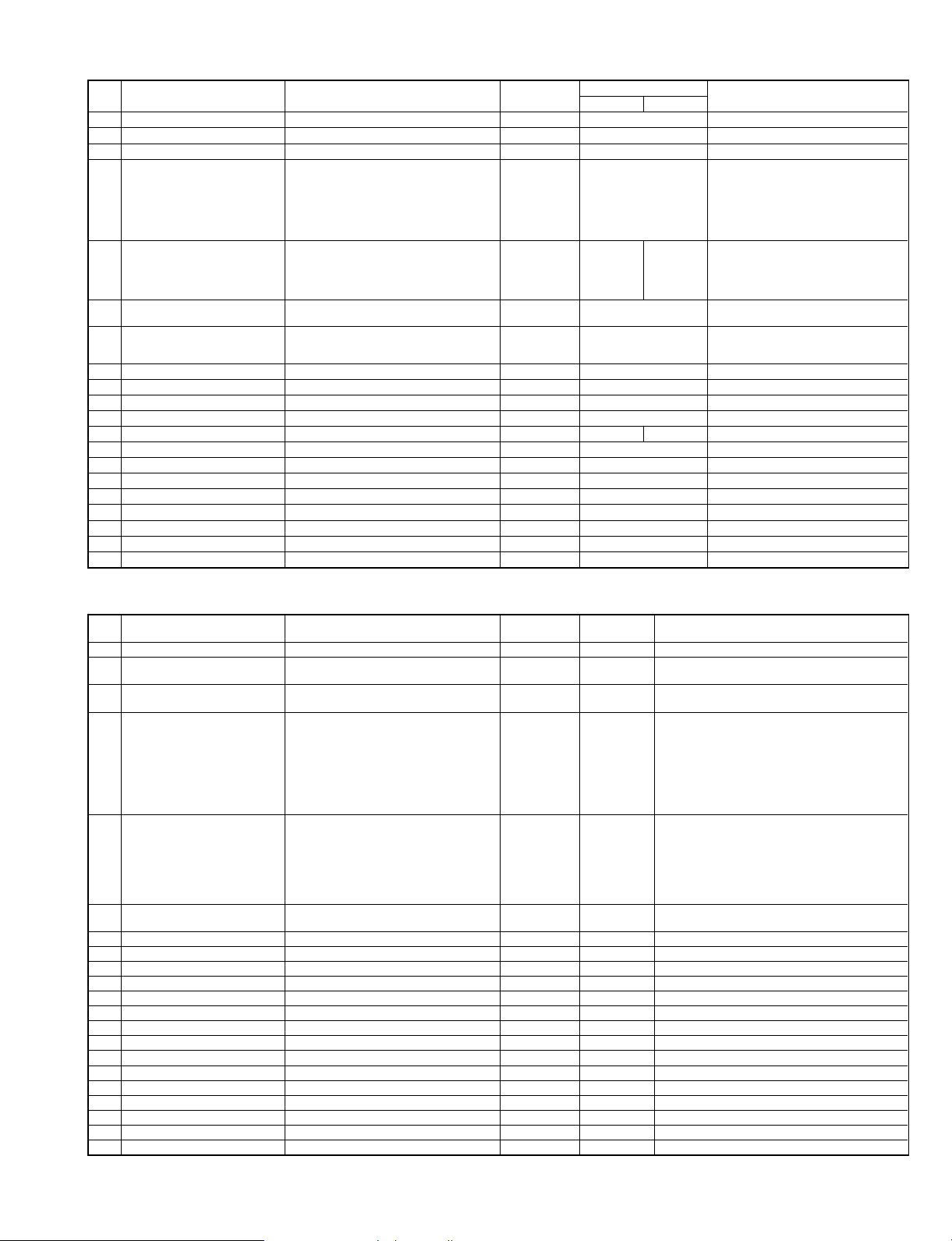
AR-405/407
No. ITEM CONTENTS LIFE
1 Drum OPC Drum ´1 180K AR-400DM
2 Developer (Black) Developer (800g) ´10 90K (´10) AR-400LD AR-400LD = (AR-400DV) ´ 10
3 Toner (Black) Toner Cartridge (700g) ´10 22K (´1) AR-400LT AR-400LT = (AR-400T) ´ 10
Cleaner Blade
Charging Plate Unit
4 90K PM Kit
5 180K PM Kit
6 Staple Cartridge Staple Cartridge (SF-SC11) ´3 5K staples ´3 SF-SC11
7 Staple Cartridge Staple Cartridge (SF-SC12) ´3 5K staples ´3 SF-LS12
8 Cleaner Blade Cleaner Blade ´10 90K (´10) AR-330CB AR-330CB= (AR-330BL) ´10
9 Upper Heat Roller Upper Heat Roller ´1 180K AR-400HU
10 Fusing Separation Pawl (upper) Fusing Separation Pawl (upper) ´4 ´10 90K (´10) SF-216UP SF216UP=SF-216TP (incl.4 pawls) ´10
11 Heat Roller Gear Heat Roller Gear ´10 180K (´10) SF-216HG SF216HG= (SF216JG) ´10
12 Lower Heat Roller Lower Heat Roller ´1 180K AR-330HR AR-505HR
13 Fusing Separation Pawl (lower) Fusing Separation Pawl (lower) ´2 ´10 90K (´10) SF-240LP SF240LP=SF-240MP (incl.2 pawls) ´10
14 Drum Separation Pawl Drum Separation Pawl ´2 ´10 90K (´10) SF-240DP SF240DP=SF-240EP (incl.2 pawls) ´10
15 Screen Grid Screen Grid ´10 90K (´10) AR-330SU AR-330SU= (AR-330TU) ´10
16 Charging Plate Charging Plate ´10 90K (´10) AR-330PU AR-330PU= (AR-330NU) ´10
17 Waste Toner Bottle Waste Toner Bottle ´1 AR-330TB
18 Busing Busing ´2 ´10 180K (´10) SF-240BU SF-240BU= (SF-240DU) ´10
19 Ozone Filter Ozone Filter ´10 90K (´10) AR-330FL AR-330FL= (AR-330JL) ´10
20 MC Unit MC Unit ´10 AR-330MC AR-330MC= (AR-330NC) ´10
Waste Toner Bottle
Fusing Separation Pawl (upper)
Fusing Separation Pawl (lower)
Screen Grid
Drum Separation Unit
Upper Heat Roller
Lower Heat Roller
Toner Receiving Seal
DV Seal
Heat Roller Gear
´1
´1
´3
´4
´2
´1
´1
´1
´1
´1
´1
´1
90K AR-400KA
180K AR-400KB AR-407KB
Note: Maintenance parts other than mentioned above must be ordered through the parts department using the proper part number.
MODEL NAME
AR-405 AR-407
REMARKS
Cartridge for AR-FN1
Common with S55,S55 N
Cartridge for AR-FN2
Common with S54
SF-LS12= (SF-SC12) ´3
AR-505/507
No. ITEM CONTENTS LIFE
1 Drum OPC Drum ´1 250K AR-500DM
2 Developer (Black) Developer (800g) ´10 250K (´10)
3 Toner (Black) Toner Cartridge (700g) ´10 25K (´10)
Cleaner Blade
Charging Plate Unit
Waste Toner Bottle
4 125K PM Kit
5 250K PM Kit
6 Staple Cartridge Staple Cartridge (SF-SC11) ´3 5K staples ´3 SF-SC11
7 Cleaner Blade Cleaner Blade ´10 125K (´10) AR-330CB AR-330CB= (AR-330BL) ´10
8 Upper Heat Roller Upper Heat Roller ´1 250K AR-505HU
9 Fusing Separation Pawl (upper) Fusing Separation Pawl (upper) ´4 ´10 125K (´10) AR-505UP AR-505UP=AR-505TP (incl.4 pawls) ´10
10 Heat Roller Gear Heat Roller Gear ´10 250K (´10) SF-216HG SF216HG= (SF216JG) ´10
11 Lower Heat Roller Lower Heat Roller ´1 250K AR-505HR
12 Fusing Separation Pawl (lower) Fusing Separation Pawl (lower) ´2 ´10 125K (´10) SF-240LP SF240LP=SF-240MP (incl.2 pawls) ´10
13 Drum Separation Pawl Drum Separation Pawl ´2 ´10 125K (´10) AR-505DP AR-505DP=AR-505EP (incl.2 pawls) ´10
14 Screen Grid Screen Grid ´10 125K (´10) AR-330SU AR-330SU= (AR-330TU) ´10
15 Charging Plate Charging Plate ´10 125K (´10) AR-330PU AR-330PU= (AR-330NU) ´10
16 Waste Toner Bottle Waste Toner Bottle ´1 AR-330TB
17 Busing Busing ´2 ´10 250K (´10) SF-240BU SF-240BU= (SF-240DU) ´10
18 Ozone Filter Ozone Filter ´10 125K (´10) AR-330FL AR-330FL= (AR-330JL) ´10
19 Ozone Filter 50 Ozone Filter 50 ´10 125K (´10) AR-505FL AR-505FL= (AR-505JL) ´10
20 MC Unit MC Unit ´10 AR-330MC AR-330MC= (AR-330NC) ´10
21 Curl Adjustment Roller Curl Adjustment Roller ´10 250K (´10) AR-505KR AR-505KR= (AR-505JR) ´10
Fusing Separation Pawl (upper)
Fusing Separation Pawl (lower)
Screen Grid
Drum Separation Unit
Cleaning Roller
Upper Heat Roller
Lower Heat Roller
Toner Receiving Seal
DV Seal
Heat Roller Gear
Curl Adjustment Roller
Upper CL Roller Unit
´1
´1
´3
´4
´2
´1
´1
´1
´1
´1
´1
´1
´1
´1
´1
125K AR-505KA
250K AR-505KB
Note: Maintenance parts other than mentioned above must be ordered through the parts department using the proper part number.
MODEL
NAME
AR-500LD
(AR500DV)
AR-500LT
(AR-500T)
REMARKS
(AR-500DV) ´10 = AR-500LD
(AR-500T) ´10 = AR-500LT
Cartridge for AR-FN1/FN1N/FN3
Common with S55,S55 N
3 – 10 7/13/2000
Page 30
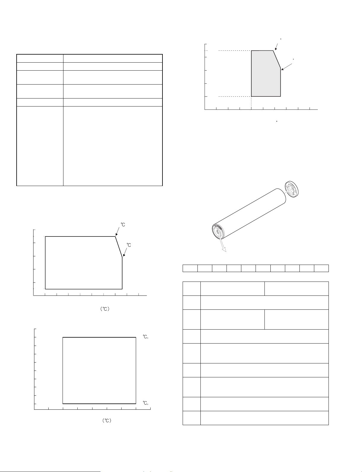
2. Copy paper
The following conditions for copy quality and transportability of PPC
paper must be satisfied. The values are at temperature of 20 ±1°C
and 65 ±2% RH.
Item Standard
Weight 56 ~ 80g/m
Smoothness Face: 20 sec or above (BEKK method)
Back: 20 sec or above (BEKK method)
Rigidness Length 17cm or above, width 13cm or
above (CLARK method)
Thickness 75 ~ 110m
Dimensions Standard dimensions ± 1mm (5/128")
B4 (257 ±1 ´ 364±1mm)
B5 (182 ±1 ´ 257±1mm)
B6 (128 ±1 ´ 182±1mm)
A3 (297 ±1 ´ 420±1mm)
A4 (210 ±1 ´ 297±1mm)
A5 (148 ±1 ´ 210±1mm)
A6 (105 ±1 ´ 148±1mm)
11" ±5/128 ´ 17" ±5/128 inch
8.5" ±5/128 ´ 14" ±5/128 inch
8.5" ±5/128 ´ 11" ±5/128 inch
5.5" ±5/128 ´ 8.5" ±5/128 inch
8.5" ±5/128 ´ 13" ±5/128 inch
2
3. Environment conditions
B. Use conditions
(%)
100
85%
80
60
40
Humidity
20%
20
0
-30 -20 -10 0 20 30 40 50 60
Use environment
conditions
10
Temperature
C
30 85%
35 60%
( C)
C
C. Life (packed conditions)
Photoconductor drum (36 months from the production month)
Developer, toner (24 months from the production month)
4. Production number identification
A. Photoconductor drum
A. Transport conditions
1) Transport condition
(%)
100
90%
80
60
40
Humidity
20
10%
0
-30 -20 -10 0 20 30 40 50 60
2) Storage condition (packed conditions)
100
90
80
70
(%)
60
50
40
Humidity
30
20
10
10
Temperature
Temperature
40
45
90%
60%
40 90%
40
10%
50403020100-10-20
<TYPE A>
12345678910
AR-280/285/335
Numeral
1
The sensitivity of the photo conductor.
Alphabet
2
The model code, "C" for
this model.
Numeral
3
The last digit of the production year.
Numeral or X, Y, Z
4
The production month.
X means October, Y November, and Z December.
Numeral
5, 6
The production day
Numeral or X, Y, Z
7
The packing month.
X stands October, Y November, and Z December.
Numeral
8, 9
The packing day.
Alphabet
10
The division of the production factory.
AR-250/281/286/287/
336/337/405/407
Alphabet
The model code, "D" for
this model.
7/13/2000 3 – 11
Page 31

<TYPE B> (AR-280/285/335/501/505/507)
11
12345678910
Numeral
1
This function: "2"
Alphabet
2, 3
The applicable model. PC (AR-280/285, 335),
PH (AR-505) for this model.
Numeral
4
The last digit of the production year.
Numeral or X, Y, Z
5
The production month.
X stands for October, Y November, and Z December.
Numeral
6
The production lot.
Numeral
7
The distinction of sub lot.
Numeral or X, Y, Z
8
The packing month.
X stands for October, Y November, and Z December.
Numeral
9, 10
The packing day.
Numeral or alphabet
11
The product name of the drum. (except AR-501/505)
B. Developer/Toner
AR-280/285/335
123456—7
AR-250/281/286/287/336/337
<Developer>
12345678
1
2
3, 4
5, 6, 7
8
<Toner>
None
<Example>
C9112102 C The manufacturing factory
Alphabet
The manufacturing factory.
Numeral
The last digit of the production year.
Numeral
The production month.
Numeral
The last 3 digits of 4-digit production lot number of
developer.
Numeral
Distincts the production lot every 100 cases.
9 The year is 1999.
11 The production month is November.
210 The production lot number is 1210.
2 This lot is between 101th case and 200th case
production this month.
1, 2, 3
Numeral
The production lot.
Numeral
4
The distinction of sub lot.
AR-405/407/501/505/507
<Developer>
12345678
1
2
3, 4
5, 6, 7, 8
<Toner>
3, 4, 5, 6, 7
Alphabet
The manufacturing factory.
Figure
The end digit of the production year.
Figures
The production month.
Figures
The manufacturing factory management number
12345678
1
2
8
Numeral
The last digit of the production year.
Numeral or alphabet
The first digit of the serial No.
Numeral
Serial No. of one month production
Numeral or alphabet
The production month.
3 – 12 7/13/2000
Page 32

[4] INSTALLATION AND SETUP
(Copier installation)
1. Unpacking procedures
(1) Packing form
Unpack the copier package in the following procedures.
1) Remove the PP bands (4 pcs.).
2) Remove the packing case.
3) Remove the internal packing pad.
4) Remove the copier body.
1
6
1
7
1 Packing case
2 Top pad
3 Support
4 Copier body
5 Bottom case
6 PP band
7 Skid unit
2
4
3
5
(2) Protection material and fixing material removal
1) Remove the fixing tape of the copier body.
In the case of SPF
In the case of RADF
6
7
7/13/2000 4 – 1
Page 33

In the case of RSPF
2) Remove the protection material and protection sheet.
In the case of SPF
· Paper exit side · Paper feed side
In the case of RADF
In the case of RSPF
illust: AR-335
4 – 2 7/13/2000
Page 34

2. Installing procedure
(1) Copier body
A. Optical system lock release
1) Release the No. 2/3 mirror unit lock.
Remove the fixing screw (1 pc.) of the No. 2/3 mirror unit on the
left side.
C. Charger cleaning
Main charger unit electrode cleaning
1) Open the front cabinet
2) Press the hook section of the main charger unit to release lock.
Pull out and remove the main charger unit from the copier body.
B. Fusing unit
Heat roller pressure check
1) Pull out the tray paper exit unit from the copier.
2) Check that the heat roller is in pressing state.
(Factory setting: The heat roller is set in pressing state before
shipment.)
AR-280/285/335
3) Remove the fixing screw (1 pc.) of the electrode section on the
back of the main charger unit.
4) Push the electrode cleaner onto the electrode tip so that the electrode tip comes into the electrode cleaner to clean. (repeat two or
three times.)
AR-250/281/286/287/336/337/405/501/505
Since the pressure lever is not installed, there is no need to check.
7/13/2000 4 – 3
Electromagnetic
cleaner
Electromagnetic
section
Note: Do not move the electrode cleaner with the electrode tip in it.
When cleaning, clean all the electrodes evenly.
Page 35

5) Install the electrode to the original position and fix with the fixing
screw (1 pc.).
6) Insert the main charger unit completely into the copier along the
guide groove.
Transfer/separation charger unit wire cleaning
1) Slightly lift the transport section open/close lever and tilt it to the
right.
2) Remove the driver transfer separation charger fixing screw, and
remove the transfer/separation charger unit from the copier body.
3) Remove the separation charger guide from the charger case.
4) Squeeze the transfer/separation charger wire with the charger
cleaner, and move it in the direction of the arrow which is indicated on the charger to clean.
AR-501/505/507: Perform the following procedure if necessary.
After removing the TC charger in procedure 2), wipe the lamp
which can be seen from the square hole of the TC guide rail with
waste cloth.
5) Install the separation charger to the charger case, and insert the
transfer/separation charger unit along the guide groove completely to the bottom.
Then, tighten the transfer/separation charger fixing screw, return
the transport section open/close lever to the left, and close the
front cabinet.
D. Accessory installation
1) Tray installation
Tray
illust: AR-335
4 – 4 7/13/2000
Page 36

E. Upper and lower trays setting
1) Remove the tray packing fixing screw.
Lift the tray holder, and pull out the tray from the copier body until it
stops.
Remove the packing fixing screw (1 pc.) of the tray paper pressing
plate.
F. Paper size change
1) Fit the tray size lever to the size of paper to be used.
(The size lever is of the slide type. Slide it right and left to fit with the
size of paper to be used.)
4) Change the display of the paper size display.
Paper size
display
R
A5
SPECIAL
B5
B5
A3
B4
A4
R
A4
Paper size
display
This section is folded
inside.
5) Install the tray.
Size lever
2) Fit the partitioning plates A and B to the paper size.
Partitioning plate A
Partitioning plate B
3) Put paper on the tray.
Set paper on the tray. At that time, do not exceed the indication
line.
Note: Push the tray completely to the bottom.
G. Developing unit setting
(1) Remove the developing unit
1) Open the front cabinet.
2) Tilt the developing unit lever toward you, and pull out the toner
cartridge until it stops.
7/13/2000 4 – 5
Page 37

3) Slide the developing unit lock lever in the arrow direction to release lock. Hold the toner cartridge holder and slowly pull out the
developing unit until it stops.
2) Supply developer from the developer supply port of the developing unit.
4) Hold the developing unit strap, slide the developing unit lock lever
in the arrow direction again to release lock, and remove the developing unit.
(2) Supply developer.
1) Disconnect the 5P connector which connects the toner hopper
and the developing unit. Then remove the toner hopper fixing
screws (4 pcs.) of the developing unit.
3) Fix the toner hopper to the developing unit with the fixing screws
(4 pcs.) and connect the 5P connector between the toner hopper
and the developing unit. At that time, put the 5P connector harness in the harness clamp attached to the toner hopper, and
process the harness.
illust.: AR-280
illust.: AR-280
4 – 6 7/13/2000
Page 38

(3) Install the developing unit to the copier body.
Install the developing unit to the copier body and push it into the body
completely. Close the developing unit lever and the front cabinet.
Note: Be careful that this procedure is different from the conven-
tional simulation.
H. Toner density sensor level adjustment
Turn on the power switch of the copier.
Note: Before executing SIM 25-1 or SIM 25-2, be sure to check that
the main charger unit is securely inserted.
(1) Adjust the developing unit toner density sensor level.
1) Execute SIM 25-2
I. Toner supply
(1) Supply toner.
1) Open the front cover.
2) Tilt the toner box lever toward you, and pull out the toner box.
Program
key
Interruption
key
C
Clear
key
Interruption
key
2
5 2P
Start key Start key
2) The touch panel shows the following display.
Touch the EXECUTE on the touch panel and execute SIM 25-2.
3) Adjustment is automatically made with the toner density sensor
output value displayed. After 3 min from starting stirring, the toner
density sensor is sampled 16 times and the average value is
stored as the toner density adjustment value.
Note: When the simulation is canceled before completion, automatic
reading cannot be made. Be careful not to cancel before completion.
4) Press the [CA] key to cancel SIM 25.
Note: SIM 25-2 must be executed only when developer is replaced.
For checking of the developer adjustment value in servicing,
use SIM 25-1. (Use of SIM 25-2 to check the developer adjustment value in servicing may cause abnormality in the toner
density transition.)
Be careful that this simulation is different from the conventional simulations.
3) Tap the top of the toner cartridge several times, and shake the
toner cartridge vertically about 20 times.
Turn the toner cartridge upside down, and vigorously shake it
vertically about 20 times again.
5X
20X
20X
4) Attach the toner cartridge to the toner box.
In the case of AR-501/505/507
7/13/2000 4 – 7
Page 39

In the case of other models
Insert two projections of the toner cartridge into the notches of the
toner supply port.
5) Move the toner cartridge in the arrow direction until it stops.
In the case of AR-501/505/507
In the case of other models
Take off the seal end and slowly remove it.
When removing the seal, hold and fix the toner cartridge.
7) Tap the top of the toner cartridge several times.
In the case of other models
6) In the case of AR-501/505/507
Pull the lever in the direction of the arrow until it breaks off.
Then pull the lever in the direction of the arrow to remove the
seal.
This is to shake off toner attached to the side surface of the toner
cartridge.
8) Move the empty toner cartridge in the arrow direction and remove
it.
9) Push the toner box to the original position, and put the toner box
lever to the original position.
Sealing tape
4 – 8 7/13/2000
Page 40

10)CLose the front cabinet.
L. Others
(1) Touch panel contrast adjustment
1) Press the CUSTOM SETTINGS key.
J. Connect the tray connector for RADF
* Temporarily fix tray fixing screw (M4 x 8), and connect the RADF
connector with the tray connector.
Tray side connector
Tray
fixing
screw
ADF side connector
K. Install the tray
* Install the tray as shown in the figure below, and tighten the fixing
screws (2 pcs.).
2) Press the "DISPLAY CONTRAST" key on the touch panel.
3) Press the "LIGHTER" or "DARKER" key to adjust the contrast.
Tray
fixing
screw
Tray
7/13/2000 4 – 9
4) Press the "OK" key.
Page 41

[5] EXTERNAL VIEW AND INTERNAL STRUCTURE
1. Common section
A. Exterior
20
7
6
18
198
12345 6 7
8
5
illust: AR-280/281
illust: AR-285/286/287/335/336/337
20
67 19
18
illust: AR-405/407
14
15
16
17
5
4
5
illust: AR-501/505/507
20 7 8
illust: AR-501/505/507
910111213
1 Exit area cover 8 Document feeder tray 15 Paper clip tray
2 Power switch 9 Paper trays 16 Bypass tray paper guides
3 Second tray 10 Front cover 17 Bypass tray
4 Output tray 11 Handles 18 Document feeder indicators
5 Operation panel 12 Right side cover 19 RADF exit roller cover
6 SPF/RADF/RSPF exit area 13 Toner collecting container cover 20 RADF/RSPF feeding roller cover
7 Original guides 14 Document glass
14
15
6
14
15
B. Interior
1234 5
6
7
1 Fusing unit
2 Transport lever
3 Photoconductive drum
4 Corona unit
5 Toner hopper
6 Roller rotating knobs
7 Paper guide
illust: AR-280
5 – 1 7/13/2000
Page 42

C. Operation Panel
(1) Key position
illust: AR-405 illust: AR-280
ON LINE
DATA
PRINT
COPY
DATA
PRINT
COPY
ON LINE
1
2345678
SPECIAL
MODES
2-SIDED
COPY
OUTPUT
INFORMATION
CUSTOM
SETTINGS
REVIEW
1
4 5
7
AUDIT CLEAR
2 3
8 9
PROGRAM
0
6
P
INTERRUPT
CLEAR
C
CA
CLEAR ALL
START
The key and indicators
are not used for the
copier features.
(2) Touch Panel
12 34
These keys are not
5
used for the copier
features.
910
11
1 2-SIDED COPY key 9 COPY key
2 SPECIAL MODES key 10 OUTPUT key
3 LCD touch panel 11 REVIEW key
4 INFORMATION key 12 AUDIT CLEAR key
5 CUSTOM SETTINGS key 13 PROGRAM key
6 10-key pad 14 Clear key
7 INTERRUPT key and indicator 15 START key and indicator
8 CLEAR ALL key
12
13 14 15
READY TO COPY.
ORIGINAL
8½X11
8½X11R
1
1.8 / 11
2
2.11 17
1
AUTO
AUTO 8 / 11
1
2
100%
EXPOSURE PAPER SELECT COPY RATIO
illust: AR-280
5
6
7
8
10
9
7/13/2000 5 – 2
1 Message display
2 Paper size display
3 Copy quantity display
4 Original size display
5 EXPOSURE display
6 EXPOSURE key
7 PAPER SELECT display
8 PAPER SELECT key
9 COPY RATIO display
10 COPY RATIO key
Page 43

2. Copier body
A. Major parts
40
39
38
37
36
35
34
33
32
41
11123 45687 9 10
12
13
14
15
16
17
18
19
20
21
22
31 30 29 28
No. Name
1 Copy lamp
2 No. 1 mirror
3 Laser scanning unit
4 Drum separation pawl
5 Waste toner collecting screw
6 Discharge lamp
7 Main charger
8 CCD unit
9 Developing unit magnet roller
10 Toner hopper
11 Hard disk
12 Resist roller
13 Paper transport roller
14 Manual paper feed tray separation roller
15 Manual paper feed tray paper feed roller
16 Paper transport roller
17 Upper tray paper feed roller
18 Paper transport roller 3
19 Upper tray paper separation roller
20 Lower tray paper feed roller
21 Paper transport roller 4
This illustration is strictly for the purpose of
showing the location of the components.
24252627
23
No. Name
22 Lower tray paper separation roller
23 Separation lamp
24 Transfer charger
25 Separation charger
26 OPC drum
27 Suction belt
28 Fusing heater lamp (Outside/inside)
29 Lower fusing roller
30 Lower fusing roller separation pawl
Lower paper exit tray gate (AR-280/285/335/501/505/507
31
only)
32 Paper exit roller 3 (AR-280/285/335 only)
Paper exit roller 1
33
(Curl correction roller for AR-501/505/507)
34 Upper paper exit tray gate
35 Paper exit roller 2
36 Upper fusing roller separation pawl
37 Upper fusing roller
38 Thermistor (Outside/inside)
39 Thermostat
40 No. 3 mirror
41 No. 2 mirror
It is not an actual model.
5 – 3 7/13/2000
Page 44

B. PWB location
25
24
26
12 3
6
5
12 3
4
7
8
5
4
6
7
8
9
25
24
26
10
11
12
13
10
11
12
14
23
22
21
20
19
18
No. Name Function, operation
1 Operation key PWB L Key input
2 LCD unit
3 Operation key PWB R Key input
4 Invertor PWB LCD backlight control
5 Operation control PWB
6 Fusing interface PWB Fusing unit, PCU interface
7 Copy lamp lighting PWB Copy lamp lighting control
8 CCD PWB Document image input
Copy lamp lighting interface
9
PWB
Document size detecting
10
PWB (Light emitting side)
11 Interface PWB
12 Scanner driver PWB
13 SCSI interface PWB
Operation input, machine
state display
Operation input, display
control
Copy lamp, PCU interface
Document size detection
Interface between the copy
lamp and the PCU
Optical system scanner unit
drive
Interface between the ICU
and the SCSI cable
17
15
16
illust: AR-280
23
22
21
20
19
18
No. Name Function, operation
14 PCU PWB
15 AC power PWB AC power input
16 DC power PWB DC power supply
17 High voltage PWB
18 Lift-up motor PWB
19 Paper transport sensor PWB Paper transport detection
20 ICU PWB
21 Process thermistor PWB
22 Drum marking sensor PWB
Multi feed tray paper size
23
detection PWB
24 Process control PWB
Document size detecting
25
PWB (Light receiving side)
26 Discharge lamp PWB OPC drum discharge
17
Overall control of the copier
and options
Process high voltage, bias
voltage supply
Paper tray bottom plate lift
up
Image process, image data
communication control
Temperature detection in
the process unit
Document size detection
Document size detection
15
16
illust: AR-505
14
7/13/2000 5 – 4
Page 45

C. Sensor location
31 32 33 1 3
34,35
236
30
29
28
27
26
25
24
23
22
21
20
19
18
4
5
6
8
7
9
10
11
12
14,1516,17
13
No. Signal name Function, operation
1 OCSW Document cover open/close detection
Operation
2
PWB
thermistor
3 PSD Separation detection
4 PPD2 PS paper detection
5 MPED Manual paper feed paper empty detection
6 MPLD1 Manual paper feed paper length detection 1
7 MPLD2 Manual paper feed paper length detection 2
8 MPLS1 Manual paper fed tray pull-out detection 1
9 MPLS2 Manual paper feed tray pull-out detection 2
10 PPD1 Paper transport detection 1
11 DSWR Right door open/close detection
12 PFD Paper transport detection 1
13 TFD Waste toner full warning detection
14 LUD1 Upper cassette upper limit detection
15 PED1 Upper cassette paper empty detection
16 LUD2 Lower cassette upper limit detection
17 PED2 Lower cassette paper empty detection
18 LCSPD1 No. 2 tray paper remaining detection 1
19 UCSPD1 No. 1 tray paper remaining detection 1
20 DPPD3 ADU tray paper in detection 3
21 DPPD2 ADU tray paper in detection 2
Operation PWB peripheral temperature
detection
This illustration is strictly for the purpose of showing the location of the components.
It is not an actual model.
No. Signal name Function, operation
22 DPPD1 ADU tray paper in detection 1
23 DSWLL Left lower door open/close detection
24 DH SW Dehumidifier heater switch
25 MEM SW Memory switch
26 POD3 Paper exit detection (Second paper exit)
27 DSBD ADU reverse section detection
28 POD2 Paper exit detection (ADU)
29 DSWL Left upper door open/close detection
30 POD1 Paper exit detection (after fusing)
31 MAIN SW Power switch
32 MHPS No. 1 mirror home position detection
33 DSWF Front cover open/close detection
Fusing
34
35
36
section
thermistor
(Center)
Fusing
section
thermistor
(Sides)
Process
section
thermistor
Heat roller temperature detection
Heat roller temperature detection
Process section peripheral temperature
detection
5 – 5 7/13/2000
Page 46

D. Motor location
12
11
13
14
15
16
16
17
20
14
1
2
11
13
12
18
19
15
1
2
3
4
3
4
10
9
8
illust: AR-280
7
No. Abbreviation Name Type
1 SFM Suction fan motor Fan motor
2 SCM Scanner motor Stepping motor
3 MM Main motor Brushless motor
4 TM Toner motor Synchronous motor
5 LUM1
6 LUM2
Upper stage lift-up
motor
Lower stage lift-up
motor
Synchronous motor
Synchronous motor
7 DCFM Power fan motor Fan motor
8 ICUFM ICU fan motor Fan motor
9 LSUFM LSU fan motor Fan motor
10 PCFM Process fan motor Fan motor
E. Clutch solenoid
123 4
5
6
10
21
9
22
8
5
6
7
No. Abbreviation Name Type
11 VFM1 Exhaust fan motor 1 Fan motor
12 VFM2 Exhaust fan motor 2 Fan motor
13 VFM4 Exhaust fan motor 4 Fan motor
14 VFM5 Exhaust fan motor 5 Fan motor
15 VFM3 Exhaust fan motor 3 Fan motor
16 VFM6 Exhaust fan motor 6 Fan motor
17 VFM8 Exhaust fan motor 8 Fan motor
18 FSM Fusing motor Brushless motor
19 VFM7 Exhaust fan motor 7 Fan motor
20 POM Paper exit motor Stepping motor
21 DSBM Reverse motor Stepping motor
22 DASM Alignment motor Stepping motor
123 4
5
17
6
7
8
9
illust: AR-280
1112
10
No. Abbreviation Function, operation
1 PSPS Paper separation solenoid
2 RRC Resist roller clutch
3 MTRC Transport roller clutch (low)
4 MPFC Manual paper feed clutch
5 MPFS Manual paper feed solenoid
6 TRC2 Paper transport clutch
7 TRC1H
Vertical transport roller/paper feed roller
high clutch
8 CPFC1 Upper stage cassette paper feed clutch
9 CPFS1 Upper cassette paper feed solenoid
7/13/2000 5 – 6
17
16
15
illust: AR-505
1314
1112
10
No. Abbreviation Function, operation
10 CPFC2 Lower cassette paper feed clutch
11 CPFS2 Lower cassette paper feed solenoid
12 TRC1L
Vertical transport roller/paper feed roller low clutch
13 DTC2 Transport clutch 2
14 DTC1 Transport clutch 1
15 DSBS
16 DSCS
Selection of paper exit to the lower stage of the
2-tray paper exit unit and the reverse route
Selection of paper retaining and transport in
paper reversion
17 OGS Two-stage paper exit tray solenoid
5
6
7
8
9
Page 47

F. 2-tray paper exit unit
5
3
2
1
No. Code Name Type Function and operation
1 POD3 Paper exit detector (Lower stage) Photo transmission Detection of paper exit to the lower tray
2 POD2 Paper exit detector (Upper stage) Photo transmission Detection of paper exit to the upper tray
3 DSBD ADU reverse detector Photo transmission Detection of reversed paper to the duplex module
4 POD1 Paper exit detector Photo transmission Detection of paper exit
5 — Paper exit roller — Paper exit from the tray
6 DSWL Micro switch Detection of open and close for paper exit unit
7 DGS
Reverse gate solenoid Solenoid Selection of paper exit to the lower tray or to the duplex
4
6
7
module
G. SPF (AR-280/281 only)
1
2
3
4
11
12
13
14
5
6
10
9
8
No. Code Name Type Function and operation
1 — SPF control PWB — —
2 EMPS Document detector Photo transmission Tray document empty detection
3 DTM Paper feed/transport motor Stepping motor Tray document feed/transport/exit roller drive
4 DWVR Document width sensor Variable resistor Tray document width detection
5 OPCLS Cover open/close detector Photo transmission SPF cover open/close detection
6 SIZ2 Document length detector (Small) Photo transmission Tray document length detection (for short size)
7 SIZ1 Document length detector (Large) Photo transmission Tray document length detection (for long size)
8 — Document pickup roller — —
9 — Document feed roller — —
10 — Document resist roller — —
11 REGS Resist sensor Photo transmission Tray document rear edge detection
12 POS Document exit sensor Photo transmission Tray document exit detection
13 — Document transport roller — —
14 — Document exit roller — —
7
5 – 7 7/13/2000
Page 48

H. RADF (AR-285/286/287/335/336/337/405/407 only)
1) Main parts
1
2
12
11
10
No. Function, operation
1 Original stopper
2 A21 weight plate
3 Semi-circular roller
4 Paper exit roller
5 Flapper
6 Reverse roller
7 Transport belt follower roller
8 Original transport belt
9 Transport belt drive roller
10 Paper feed roller
11 Resist roller
12 Separation roller
3
9
8
2) PWB distribution
3) Motors, solenoids, and clutches
No. Code Name Type
1 DFM Paper feed motor DC motor
4
5
2 DTM Transport motor Stepping motor
3 DRM Reverse motor Stepping motor
4 DRSOL Reverse solenoid DC solenoid
5 DFSOL Paper feed solenoid DC solenoid
3
6
2
7
4
1
5
4) Sensors, switches, detectors
1
12
11
10
9
2
3
1
2
5
3
4
No. Name Function, operation
1 Control PWB
2 Reverse sensor PWB Document reverse detection
3 LED PWB
Original timing sensor
4
PWB
Original reverse
5
sensor PWB
RADF unit control, PCU
communication
Document feed, document
remaining display
Document timing detection
Document feed detection
8
7
6
4
5
No. Code Functions and operations
1 DLS2
2 TGOD Reverse cover open/close detection
RDD Turns HIGH when the original lead edge is
3
4 DWVR Original width detection on the tray
DTD Turns HIGH when the original lead edge is
5
DFD Turns HIGH when the original lead edge is fed
6
7 DWS Original width detection
8 FGOD Paper feed cover open/close detection
9 DFMRS Paper feed motor rotation detection
10 AUOD ADF unit open/close detection
11 DSS Original detection on the tray
12 DLS1 Original length detection on the tray
Original length detection on the tray (Inch
series only)
transported to the reverse/paper exit path.
transported from the paper feed section to the
vicinity of the transport belt.
just in front of the resist roller.
7/13/2000 5 – 8
Page 49

I. RSPF (AR-501/505/507 only)
A. Roller
3
2
1
7
B. Sensor, switch, solenoid, motor
4
5
6
20
19
18
17
16
No. Name
1 Paper exit roller
2 Read roller
3 Resist roller
4 Paper feed roller
5 Separation pad
6 Pickup roller
7 SB roller
1
2
3
4
5
6
15
14
13
12
11
10
No. Code Name Type Function and operation
1 FMOT Transport motor Stepping motor Transport and document read motor
2 DCFAN Fan motor — Transport motor cooling fan
3 ACL Paper feed clutch — Document feed clutch
4 MCLKS DCMCLK Photo transmission DC motor encoder sensor
5 AMOT Paper feed motor DC motor Document feed motor
6 PBA-CONTROL Control PWB — RSPF control PWB
7 TRS-L Tray sensor L Photo transmission Document tray longitudinal direction sensor
8 TRS-S Tray sensor S Photo transmission Document tray traverse direction sensor
9 TRVR Size volume — Document tray width direction detection volume
10 EMPS Empty sensor Photo transmission Document sensor set on the document tray
11 JAMOPEN Jam open switch — RSPF jam cover open/close detection
12 SBSOL Pressure solenoid — Reversing path document pressure solenoid
13 FLPSOL2 Flapper solenoid 2 — Read roller and document exit select solenoid
14 FLPSOL1 Flapper solenoid 1 — Reversing path and read roller select solenoid
15 DFOPEN DFOPENF Photo transmission RSPF open sensor
16 RDS Read sensor Reflection Document read timing sensor
17 REJI Resist sensor Photo transmission Paper feed resist timing sensor
18 EXITS Paper exit sensor Photo transmission Document exit sensor
19 SBS SB sensor Reflection Reversing path document sensor
20 SPS Post-separation sensor Reflection Feeding document size sensor
9
7
8
5 – 9 7/13/2000
Page 50

J. ADU (AR-285/335/505/507 only)
17
16
15
14
18
1
2
3
4
5
6
13
7
12
11
10
9
8
No. Code Name Type Function and operation
1 — Reverse motor Pulse motor Paper reversion and transport drive
2 — Alignment motor Pulse motor Paper alignment plate drive
3 — Alignment belt (232MXL) — Paper transport
4 DTC1 Transport clutch 1 Electromagnetic clutch —
5 — Alignment plate home position detector Photo transmission Alignment plate home position detection
6 DTC2 Transport clutch 2 Electromagnetic clutch —
7 DPPD3 Paper in detector 3 Photo transmission ADU tray paper in detection
8 — Transport roller 3 — ADU tray paper transport
9 — Transport belt (145MXL) — Transport roller drive
10 — Transport roller 2 — ADU tray paper transport
11 DPPD2 Paper in detector 2 Photo transmission ADU tray paper in detection
12 — Transport roller 1 — ADU tray paper transport
13 — Belt B — Transport roller drive
14 DSBS Paper exit/reverse gate solenoid Solenoid
15 — Reverse roller — Selection of paper retaining and transport in paper reversion
16 DSCS Contact/detach solenoid Solenoid Selection of paper storing and transport in ADU tray
17 — Transport roller — Paper transport
18 DPPD1 Paper in detector 1 Photo transmission ADU tray paper in detection
Selection of paper exit to the lower stage of the 2-tray paper
exit unit and the reverse route
7/13/2000 5 – 10
Page 51

[6] SETTING AND ADJUSTMENTS
1. List of adjustment items
Section Adjustment item
A. Process (1) Developing doctor gap
B. Laser scanner
(exposure)
C. Scanner (1) Vertical image distortion
adjustment
(2) MG roller main pole position
adjustment
(3) Developing bias voltage
adjustment
(4) Main charger grid voltage
adjustment
(5) Transfer charger adjustment SIM8-6
(6) Separation charger bias
voltage adjustment
(7) Photoconductor marking
sensor sensitivity (gain)
adjustment
Image density sensor
sensitivity (gain) adjustment
SIM44-2
(8) Toner concentration
adjustment (auto developer
adjustment)
(1) Horizontal image distortion
adjustment
(2) Print off-center adjustment SIM50-10
(3) Laser power setting (copier
mode)
balance adjustment
(2) Vertical image distortion
balance adjustment
(3) Vertical (sub scanning
direction) distortion adjustment
[Winding pulley position
adjustment]
(4) Horizontal (main scanning
direction) distorion adjustment
[Lower rail height adjustment]
(5) Main scanning direction
magnification ratio adjustment
(6) Main scanning direction
magnification ratio adjustment
Sub scanning direction
magnification ratio adjustment
* Including the adjustment with
SPF, RSPF
(7) Copy image position, image
loss, void area adjustment
(8) Original off-center adjustment SIM50-12
* Including the adjustment with
SPF
(9) Original off-center adjustment SIM50-12
* Including the adjustment with
SPF,RADF, RSPF
Adjustment
procedure
MG roller main
pole position
adjustment
SIM8-1/44-15
SIM8-2/44-15
SIM8-7
SIM44-2
SIM44-2
SIM25-2
LSU lever
adjustment
SIM61-2/44-15
SIM61-4
Printer mode
Copy lamp
unit installing
position
adjustment
No. 2/No. 3
mirror base
installing
position
adjustment
Winding pulley
position
adjustment
F rail height
adjustment
CCD unit
position
adjustment
SIM48-1
SIM48-1
SIM50-1/2
Section Adjustment item
D. Image density
adjustment
E. Paper feed (1) Manual paper feed size
F. Paper transport (1) Separation pawl operation
G. Others (1) Original size sensor detection
H. SPF (1) Hinge height check and
I. RADF (AR-RF1)
(When the RADF is
installed)
J. RADF (AR-RF2)
(When the RADF is
installed)
K. RSPF
(1) Test chart setting SIM 46-2/9/10/
detection level adjustment
(2) Paper feed off-center
adjustment
timing adjustment
(2) Paper resist amount adjustment SIM51-2
level adjustment
(2) Original size sensor detection
level adjustment
(3) Waste toner full detection level
adjustment
(4) Touch panel adjustment SIM65-1
(5) Key touch sound volume
adjustment
adjustment
(2) Open/close sensor position
adjustment
(1) Document lead edge stop
position adjustment
(2) Resist/timing/paper exit sensor
adjustment
(3) Test mode with DIP switch
(1) Document lead edge stop
position adjustment
(2) Resist/timing/paper exit sensor
adjustment
(3) Test mode with DIP switch
Lead edge position adjustment
Magnification ratio adjustment
No. 1 resist quantity adjustment
No. 2 resist quantity adjustment
Image loss adjustment
Center shift adjustment
Reflection type sensor
adjustment
Image distortion adjustment
Back surface resist adjustment
Skew adjustment
Adjustment
procedure
11
SIM40-2
SIM51-1
SIM41-2
SIM41-1
Sound volume
adjustment
Table glass
clearance
adjustment
SIM 2-02
SIM 53-1
SIM 53-2
SIM 53-1
SIM 53-2
SIM 50-1/2/6/7
SIM 48-1
SIM 51-2
SIM 51-2
SIM 50-1/2/6/7
50-12
SIM 53-2
Distortion
screw
adjustment
SB resist plate
adjustment
Upper/lower
guide
adjustment
6 – 1 7/13/2000
Page 52

2. Copier adjustment
A. Process section
(1) Developing doctor gap adjustment
1) Remove the screw and the connector which connect the toner
hopper and the developing unit, and separate them.
2) Loosen the DV doctor fixing screw A.
3) Insert a 0.53mm (0.6mm for AR-280/285/335) thickness gauge
into the clearance of 40mm ~ 70mm from the DV doctor edge.
40mm
30mm
A
30mm
40mm
4) Press the DV doctor in the arrow direction and tighten the DV
doctor fixing screw. (Perform the same procedure for the front and
the rear frame.)
5) Check that the clearance (2 positions) at 40mm ~ 70mm from the
both ends is 0.53 ± 0.03mm (0.6 ± 0.03mm for AR-280/285/335).
* When inserting a thickness gauge, be careful not to scratch the
DV doctor and the MG roller.
17.0mm
P
2~3mm
2~3mm
17.0mm
(3) Developing bias voltage adjustment
1) Set the digital multi-meter range to the DCV range.
2) Put the test probes between the DV bias output check pin (CN2-1
pin) of the high voltage unit and the chassis (GND).
(2) MG roller main pole position adjustment
1) Remove the screw and the connector which connect the toner
hopper and the developing unit, and separate them. Put the developing unit on a flat floor.
2) Tie a needle or pin on a string.
3) Hold the string and put the needle horizontally and move it toward
the MG roller. (Do not use a clip which is too big to have a correct
position since the MG roller diameter is small.)
4) With the needle tip at 2 ~ 3 mm apart from the MG roller surface,
mark the point on the surface which is on the extended line of the
needle tip.
5) Measure the distance between the marking position and surface P
of the developing unit and check that it is 17mm.
If the distance is not as specified above, loosen the fixing screw of
the main pole adjustment plate, and move the adjustment plate to
adjust.
7/13/2000 6 – 2
Page 53

3) Execute SIM 8-1.
(AR-250/280/281/285/286/336/405)
(AR-287/337/407)
4) When the output voltage is within the adjustment range, change
the displayed value and adjust. (1 step: about 1 V)
Adjustment range
Others
Developing negative bias voltage (Auto) –500 ±5V –425 ±5V
Developing negative bias voltage
(Character)
Developing negative bias voltage
(Character, Photo)
Developing negative bias voltage
(Photo)
Developing negative bias voltage
(Toner save)
Developing bias (Printer) –500 ±5V –500 ±5V
Developing positive bias voltage +150 ±5V +150 ±5V
(The value and the output voltage may not coincide.)
–500 ±5V –500 ±5V
–500 ±5V –500 ±5V
–500 ±5V –500 ±5V
–450 ±5V –500 ±5V
AR-501/
505/507
(4) Main charger grid voltage adjustment
1) Install the DV unit, the drum holder unit, and the charger units to
the copier.
2) Turn on the main switch, and execute SIM 8-2 to check the grid
voltage set value.
(AR-250/280/281/285/286/335/336/405)
(AR-501/505/507)
The DV bias can be measured without installing the OPC drum
and the developing unit.
(AR-287/337/407)
6 – 3 7/13/2000
Page 54

(AR-501/505/507)
(5) Transfer charger current adjustment
a. Special measurement tool
Electrode sheet (UKOG-0110FCZZ)
UK0G-0110FCZZ
UKOG-0110FCZZ
(Measurement at the high voltage PWB check point)
3) Remove the rear cabinet.
4) Connect the digital multi-meter to the grid voltage output check pin
(CN2-5 pin).
5) Set the digital multi-meter range to the DCV range.
(Use a digital multi-meter which allows measurement up to
DC1000 V.)
6) Manually turn on the door switch.
7) Turn on the main switch, and execute SIM 8-2 to check.
Electrode sheet harness (DHAI-0304FCZZ)
Orange
(Microswitch)
(QSW-M0118FCZZ)
Orange
Orange
PHOG-0007FCZZ
QTIPH0017FCZZ
(Parts arrangement)
White
300KΩ X 2
(VRN-RT2EK304F)
White
A
Black
Blue
White
Red
Blue
Black
Green
Blue
Black
Yellow
Red
(QCLIZ0005FCZZ)
(QCLIZ0006FCZZ)
(QCLIZ0010FCZZ)
(QCLIZ0004FCZZ)
(QCLIZ0002FCZZ)
b. Adjustment procedure
1) Remove the developing unit, the transfer/separation charger unit,
and the main charger unit from the copier.
2) Remove the process unit from the copier.
3) Remove the OPC drum from the process unit, and install the
electrode sheet by using a rubber band, tape, etc.
4) Install the OPC drum with the electrode sheet installed to the
process unit, and install the process unit to the copier.
5) Install the drum holder unit to the copier so that the electrode
sheet lead wire can be taken out from the developing unit side.
AR-280/285/335
8) If the output voltage is not in the specified range, change the
displayed value and adjust. (1 step: about 1V)
Adjustment range
AR-280/
285/335
AR-250/281/
286/287/336/
337/405/407
AR-501/
505/507
Grid voltage (Auto) –642 ±5V –602 ±5V –570 ±5V
Grid voltage (Character) –642 ±5V –602 ±5V –645 ±5V
Grid voltage (Character,
Photo)
–642 ±5V –602 ±5V –645 ±5V
Grid voltage (Photo) –642 ±5V –602 ±5V –645 ±5V
Grid voltage (Toner save) — –552 ±5V –645 ±5V
Grid voltage (Printer) –642 ±5V –602 ±5V –645 ±5V
(The value and the output may not coincide.)
7/13/2000 6 – 4
Page 55

AR-250/281/286/287/336/337/405/407/501/505/507
6) Clean the transfer charger wire separation lamp and install the
transfer/separation charger unit to the copier.
If necessary, wipe the lamp which can be seen from the square
hole of the TC guide rail with waste cloth.
(Do not install the main charger unit.)
7) Connect the electrode sheet and the digital multi-meter (or an
ampmeter). Manually turn on the door switch.
8) Check the drum current on the front frame side and the rear frame
side.
The current on the front and the rear frame sides: within 6.0uA
· Turn on the main switch, and execute SIM 8-6.
(THVG will be turned ON for about 30 sec.)
· Measure the drum current on the front frame side and the rear
frame side.
· When the microswitch is OFF, the drum current on the front
frame side is displayed.
· When the microswitch is ON, the drum current on the rear
frame side is displayed.
(ON)
N/C
N/O COM
(OFF)
N/C
N/O COM
· Check that the current on the front and the rear frame side is
6.0mA or less.
If the current is greater than 6.0mA, replace the charger unit
with new one.
9) Adjust THVG output current.
· Turn on the main switch and execute SIM 8-6.
(AR-250/280/281/285/286/335/336/405)
(AR-287/337)
(AR-407)
(AR-501/505/507)
(THVG will be turned on for about 30 sec.)
· If the output current is not in the specified range, change the
displayed value and adjust. (1 step: about 0.1 mA)
Adjustment spec
Transfer charger current
TC drum current
(Front surface mode)
TC drum current
(Back surface mode)
AR-250/280/281/
285/286/287/
335/336/337
+13.5 to
+15.0mA
+13.5 to
+15.0mA
AR-405/407
+15.0 to
+16.5mA
+15.0 to
+16.5mA
AR-501/
505/507
+18.0 to
+19.5mA
+18.0 to
+19.5mA
6 – 5 7/13/2000
Page 56

Body chassis
(no coating)
R
Yellow grip
Black grip
Black
Blue
2
20
200
F
(DCmA)
Blue grip
Green grip
Red
Orange
White
White
(AR-407)
Orange
Microswitch
(AR-501/505/507)
Digital multi-meter
Red grip
(UKOGE0043FC01)
* Check that the black clip is securely grounded to the machine
chassis.
When UKOGE0043CS01 is used:
Knob 1: Set to DCmA.
Knob 1: Connect to 2.
Red clip: Connect to (+).
Blue clip: Connect to (–).
When an ampmeter is used:
Red clip: Connect to (+) of the ammeter.
Blue clip: Connect to (–) of the ammeter.
(6) Separation charger DC component voltage
1) Install the DV unit, the drum holder unit, and the charger units to
the copier.
2) Remove the rear cabinet.
3) Connect the digital multi-meter to SHVG output check pin (CN2-3
pin).
4) Set the digital multi-meter range to the DCV range.
5) Manually turn on the door switch.
6) Execute SIM 8-7. (SHVG will be turned on for about 30 sec.)
(AR-250/280/281/285/286/335/336/405)
7) If the output voltage is not in the specified range, change the
displayed value and adjust. (1 step: about 1V)
Adjustment range
Separation DC component
voltage (Front surface mode)
Separation DC component
voltage (Back surface mode)
AR-250/280/281/
285/286/287/
335/336/337
–140 ±10V –150 ±10V –200 ±10V
–140 ±10V –150 ±10V –200 ±10V
AR-405/
407
AR-501/
505/507
(7) OPC drum marking sensor/Image density sensor
gain adjustment
This adjustment must be performed in the following cases:
· When both sensors are cleaned in maintenance.
· When the value of DMLED/PCLED in SIM 44-12 are greater than
about 100.
Clean both sensors and perform the adjustment.
1) Execute SIM 44-2.
(AR-250/280/281/285/286/287/335/336/337)
(AR-287/337)
7/13/2000 6 – 6
(AR-405/407/501/505/507)
2) When the adjustment is completed, the gain value is displayed. If
an error occurs during the adjustment, the error display is made.
Page 57

(8) Toner density adjustment
(Auto developer adjustment)
This adjustment must be performed in the following case:
· When new developer is supplied.
1) Execute SIM 25-2.
2) The adjustment is automatically made with the toner density sensor output value displayed. After 3 minutes from starting stirring,
the toner density sensor is sampled 16 times, and the average
value is stored as the toner density adjustment value.
* When new developer is supplied, clear the developer counter
with SIM 24-5.
B. Laser scanner section
(1) Horizontal image distortion adjustment
1) Execute SIM 64-1, and print the pattern of SQUARE from the
manual feed tray.
(A: 22 E: 1)
(AR-250/280/281/285/286/287/335/336/337)
(AR-501/505/507)
Set items A: Self print pattern
B: Density level
C: Setting of the number of self print sheets
D: Density mode
1 Auto 3 Text/Photo
2 Text 4 Photo
E: Cassette selection
1 Manual feed 5 Desk middle cassette
2 Upper cassette 6 Desk lower cassette
3 Lower cassette 7 LCC
4 Desk upper cassette
F: Duplex print selection
1 Simplex 2 Duplex
2) Obtain value a of the printed sheet.
(AR-405/407)
a
θ
Paper exit direction
3) Turn the adjustment handle to adjust according to the value a.
AR-280/285/335
AR-250/281/286/287/336/
337/405/407/501/505/507
6 – 7 7/13/2000
Page 58

Adjustment handle: 1 scale = 0.5mm (dimension a)
q<90 degress: Right direction
q>90 degrees: Left direction
Adjustment specification: a = 0 mm, q = 90 degrees
(2) Print off-center adjustment
1) Execute SIM 64-1. print one sheet from each paper feed port.
Measure the void amount both sides.
When making duplex copy with OC, press the [CLOSE] key to
enter the copy menu and read two pages of documents.
Then press the [READ CORRECT] key.
* Select the self print pattern which allows easy measurement of
the void amount.
2) Execute SIM 50-10.
(3) Laser power setting
* Normally the laser power is automatically corrected by process
control. Use the image density adjustment described later unless
there is a special request from the user.
(AR-230/280/285/335)
All must be set to "16".
(AR-250/281/286/336)
All must be set to "7".
3) Change each value to adjust so that the void amounts of both
sides are even.
a > b: Increase the value.
a < b: Decrease the value. (See the figure below.)
a
b
4) Press the CA key to terminate the simulation.
a
b
(AR-287/337)
All must be set to "8".
(AR-405)
Set all to "5" except for PH256.
(AR-407)
All must be set to "6".
7/13/2000 6 – 8
Page 59

(AR-501/505/507)
All must be set to "5".
C. Scanner section
(1) Vertical image distortion balance adjustment
(Copy lamp unit installing position adjustment)
1) Insert the front/rear mirror base drive wire into the frame groove
and press and fix it with the wire fixing plate. At that time, do not
tighten the wire fixing screw.
Change the direction of the lamp positioning plate. (F and R)
2) Push the copy lamp unit onto the positioning plate, and tighten the
wire fixing screw.
(AR-280/285/335)
(AR-250/281/286/287/336/337/405/407/501/505/507)
* Note for assembling the copy lamp unit
Move the copy lamp unit to the paper exit side, and fix the copy lamp
unit with the harness guide so that the distance between the copy
lamp harness and the lower frame is about 24±2mm, (25 ~ 30mm)
with the copy lamp harness extended.
After fixing, manually shift the copy lamp unit a few times to check
that it moves smoothly.
If the copy lamp harness is loosely fixed, the copy lamp unit may jump
up when reading, resulting in abnormal reading.
(AR-280/285/335)
24±2mm
6 – 9 7/13/2000
Page 60

(AR-250/281/286/287/336/337/405/407/501/505/507)
25~30mm
(3) Vertical (sub scanning direction) distortion
adjustment [Winding pulley position adjustment]
This adjustment is executed in the following cases:
· When the mirror base drive wire is replaced.
· When the lamp unit, or No. 2/3 mirror holder is replaced.
· When a copy shown below is made.
(2) Vertical image distortion balance adjustment
(No. 2/3 mirror base unit installing position
adjustment)
This adjustment is to adjust the parallelism of the mirror base to the
OPC drum surface and the original surface.
1) Manually turn the mirror base drive pulley to bring mirror base B
into contact with mirror base positioning plate.
If, at that time, the front frame side and the frame side of mirror
base B are brought into contact with the mirror base positioning
plate simultaneously, the parallelism is correct and there is no
need for adjustment.
La
Paper exit
direction
Original
1) Set A3 white paper on the original table as shown below.
Allow a little space.
Glass holding plate
Fit the paper edge and
the glass holding plate edge.
2) With the original cover open, make a normal (X 1.0) copy.
3) Measure the black distance at the lead edge and the rear edge of
the copy paper.
Copy
A3 white paper
Lb
illust: AR-280
Illust: AR-280
7/13/2000 6 – 10
Paper exit direction
La: Lead edge black background section
Lb: Rear edge black background section
If La = Lb, the procedures 4) through 7) are not required.
Page 61

4) Loosen the fixing screw of the front or the rear frame mirror base
drive pulley.
· If La < Lb, turn the rear frame mirror base drive pulley in
direction B. (Do not move the mirror base drive pulley shaft.)
· If La > Lb, turn the rear frame mirror base drive pulley in
direction A. (Do not move the mirror base drive pulley shaft.)
Rear side
A
2) Make a copy of the adjustment original on an A3 white paper at
the normal magnification ratio.
(Fit the paper edge and the glass holding plate edge.)
3) Measure the distances between the lines and the corners (4 positions of La, Lb, Lc, Ld).
La
Lc
B
Front side
5) Tighten the fixing screw of the mirror base drive pulley.
6) Perform procedures 1) through 3).
7) If La is not equal to Lb, perform procedures 4) and 5).
If La = Lb, the adjustment is completed.
Repeat procedures 1) through 6) until La = Lb.
(4) Horizontal (main scanning direction) distorion
adjustment [Lower rail height adjustment]
When there is no distortion in the direction of mirror base scanning
and there is sub scanning direction distortion, it can be adjusted by
changing the No. 2/3 mirror base unit rail height.
· Before this adjustment, perform the horizontal image distortion ad-
justment in the laser scanner section.
This adjustment must be performed in the following cases:
· When the mirror base wire is replaced.
· When the copy lamp unit and no. 2/3 mirror unit are replaced.
· When the mirror unit rail is replaced and moved.
· When a copy shown below is made.
Paper exit
direction
Lb Ld
When La = Lb and Lc = Ld, no need to adjust.
When La = Lb = Lc = Ld, there is no need for adjustment.
4) Move the mirror base B rail position up and down (in the arrow
direction) to adjust.
· When La > Lb, move the mirror base B rail on the paper
exit side upward by the half of the difference of La – Lb.
· When La < Lb, move the mirror base B rail on the paper
exit side downward by the half of the difference of Lb - La.
Example: When La = 12mm and Lb = 9mm, move the
mirror base B rail on the paper exit side 1.5mm
upward.
· When Lc > Ld, move the mirror base B on the paper feed
side downward.
· When Lc < Ld, move the mirror base B on the paper feed
side upward.
* When moving the mirror base rail, hold the mirror base rail
handle.
5) Adjust so that La = Lb and Lc = Ld.
6) After completion of the adjustment, manually turn the mirror base
drive pulley to make full scanning of mirror base A and mirror base
B and check that they do not make contact.
* If the mirror base rail is moved extremely, the mirror base may
be brought into contact. Be careful of that.
Original Copy
1) Make an original for the adjustment.
Draw parallel lines at 10mm from both sides of an A3 white paper.
Parallel line
10mm
10mm
White paper
Parallel line
10mm
10mm
illust: AR-280
illust: AR-280
6 – 11 7/13/2000
Page 62

(5) Main scanning direction magnification ratio
adjustment (CCD unit installing position adjustment)
1) Execute SIM 48-1.
2) Set each value to 50 (initial value).
3) As shown in the figure below, put a scale on the original table.
10 20 3040 50 60 70 8090 50 100110120130140
A4
illust: AR-280
4) make a normal copy on A4 paper.
5) Compare the scale image length and the actual scale length.
6) Obtain the main scanning direction copy magnification ratio according to the following formula.
Main scanning direction copy magnification ratio
(Original length – Copy length)
=
(Example) Put the scale so that 50mm of the scale is at the
Original length
center of the original.
´ 100%
10) Insert the slide pin as shown below and make positioning in the
vertical direction.
11) Insert the slide pin as shown below and make positioning in the
horizontal direction.
(Initial position positioning is completed.)
Main scanning direction copy magnification ratio
100 – 98
=
100mm scale
(Original)
Copy image
(2mm (2%)
shorter than the
original)
7) Remove the original guide L and R, and remove the table glass.
8) Remove the dark box cover.
9) Remove the slide pin of the front cover unit.
´ 100 = 2
100
10 20 90 100 110
1mm
1mm
10 20 90 100 110
B
A
7/13/2000 6 – 12
Never loosen a screw other than these ones.
* Never loosen the screws which are not indicated in the figure.
If loosened, the adjustment cannot be made and the unit must be
replaced.
12) Make a sample copy in the initial position and measure the
magnification ratio again.
13) Change the installing position in the horizontal direction to adjust
the magnification ratio.
Page 63

· When the copy image is longer than the original, move in
the direction of B.
· When the copy image is shorter than the original, move in
the direction of A.
· One scale of scribe line corresponds to 0.2%.
· For fine errors which cannot be adjusted with this adjust-
ment, use the next simulation SIM 48-1.
(6) Main/sub scanning direction magnification ratio
adjustment
1) Before this adjustment, perform the previous adjustment of CCD
unit installation position.
2) Place a scale on the original table as shown. (Scale a and scale b
may be placed together or individually.)
· After warming up, the ready lamp lights up.
· The current set value is displayed simultaneously. (0 ~ 20)
10
20
30 40 50 60 70
80 90 50
102030 40 50 60 70
100
110120130140
3) Make a normal copy and obtain the main/sub scanning direction
magnification ratios.
Copy magnification ratio (MRCP)
=
(Original
dimension – Copy dimension)
Original dimension
80 90 50
Scale a
100 110 120 130 140
Scale b
illust: AR-280
´ 100%
4) Execute SIM 48-1.
(AR-501/505/507)
(Other models)
5) Change value A so that the magnification ratio in the sub scanning
direction is within the specified range.
6) Change value B so that the magnification ratio in the main scanning direction is within the specified range.
· Adjustment specification: Within ±0.8%
· When the copy dimension is smaller than the original
¯
Make the value greater.
· When the copy dimension is greater than the original
¯
Make the value smaller.
When the value is changed by one step, the ratio is changed
by about 0.1%.
(Example 1)
Copy A
(Shorter than
the original)
Scale
(Original)
(Example 2)
Copy B
(Longer than
the original)
10
10
20
20 90 100
10
20 90 100
90 100 110
110
110
Paper exit direction
a > Magnification ratio in the main scann ing direction
b > Magnification ratio in the sub scanning direction
[AR-280/281 only]
7) Make a copy of A3 original with SPF, and measure the magnification ratio in the sub scanning direction.
8) Change value C so that the magnification ratio in the sub scanning
direction is within the specified range.
9) Press the CA key to cancel the simulation.
6 – 13 7/13/2000
Page 64

(7) Copy image position, image loss, void area
adjustment
Before performing this adjustment, check that SIM 50-5 is set to 50. If
not, set it to 50.
This adjustment uses SIM 50-2 and SIM 50-1.
The above two simulations are used in the following manner.
Sim 50-2: Rough adjustment
SIM 50-1: Fine adjustment
If the desired value is obtained by SIM 50-2, there is no need to
perform SIM 50-1.
(Adjustment items)
No. Adjustment item Operation mode
1 Lead edge image loss Document
SPF mode IMAGE LOSS IMAGE LOSS 1.5 to 3.0 mm
table mode
2 Lead edge void area Document
SPF mode DEN-A DEN-A 1.5 to 3.0 mm
table mode
3 Rear edge image loss SPF mode REAR LOSS
4 Rear edge void area Document
SPF mode DEN-B DEN-B
table mode
5 Image reference position Document
table mode
6 Paper timing Document
SPF mode RRC-B
table mode
7 Image reference position SPF mode SPF
8 Distance between image lead edge
position and scale of 10mm ´ 10
Document
table mode
RSPF mode L1(L6), L4
(Distance between image lead edge
position of back surface and scale of
10mm ´ 10)
9 Distance between paper lead edge
and image lead edge ´ 10
10 Distance between image lead edge
Document
table mode
RSPF mode L2, L5
SPF mode L3
position x scale of 10mm ´ 10
Adjustment items 1 ~ 4 can be adjusted either with SIM 50-1 or SIM 50-2.
The adjustment values of items 8 ~ 10 will affect the adjustment items 5 ~ 7 automatically.
Therefore, adjusting the items 8 ~ 10 will lead to the same result as adjusting the items 5 ~ 7.
* L6 is the same as L1 for the back surface
* Refer to "K. RSPF" for the adjustment of RSPF.
SIM 50-2 set
item
(SPF)
SIM 50-1 set
item
REAR LOSS
(SPF)
RRC-A
Adjustment
value
Note
1.5 to 3.0 mm AR-4XX
series only
1) Place a scale on the document table as shown below, and
make a normal (100%) copy.
Note that the scale must be placed in parallel to the scanning
direction and that the scale lead edge must be clearly copied.
Scale
illust: AR-280
7/13/2000 6 – 14
2) Process the copied paper as shown below.
Cut the copied paper along the line at the edge of the scale
image. The cut line and the scale image must form a right angle
(90 degrees).
Scale lead edge
100
110 120 130
140
150
Paper
10 20
Cut the paper along this line.
9030 8070605040
Page 65

3) Place the scale on the document table as shown below.
Note that the scale must be placed in parallel to the scanning
direction and that the scale lead edge is in close contact with the
document guide plate.
Scale
102030 40 50 60 70
80 90 50
100 110 120 130 140
Paper (White paper)
illust: AR-280
4) Enter the SIM 50-2 mode.
5) Set the image loss and DEN-A set values to "0."
6) Set all the values of L1, L2, and L3 to "0."
7) Make a copy at 400%. (Document table mode)
8) Measure dimensions X and Y of the copied scale image.
X: Distance between the copy image lead edge and the scale
of 10mm
Y: Distance between the paper lead edge and the copy image
lead edge
X
Paper lead
edge
10 20 30 40
Y
400% enlargement copy
50
9) Set the document as in procedure 1) and 2) on the SPF, and
make a copy at 200% in the SPF mode.
10) Measure the dimension L3 of the copied scale image.
Z: Distance between the copy image lead edge and the scale
of 10mm
Z
11) Enter L1, L2, and L3 as follows:
L1 = X ´ 10
L2 = Y ´ 10
L3 = Z ´ 10
12) Cancel the simulation mode, make a copy in the document table
mode and in the SPF mode, and check that the lead edge image
loss and the void area are in the specified range as shown
below:
Lead edge image loss: 1.5 ~ 3.0mm
Lead edge void area: 1.5 ~ 3.0mm
If the above condition is not satisfied.
13) Enter the SIM 50-1 mode.
14) Set the scale on the document table in the same manner as in
procedure 3). Make a copy at 50% and at 400% in the document
table mode.
15) Measure the distance between the paper lead edge and the
copy image lead edge of 50% copy and 400% copy.
16) Check that there is no difference between the measured distance of 50% copy and that of 400% copy.
If the difference is more than 1.5mm, change and adjust the
RRC-A value.
Repeat procedures 12) to 16) until the above condition is satisfied.
17) Use the document made in procedures 1) and 2) and make a
copy at 50% and at 400% in the SPF mode.
18) Measure the distance between the paper lead edge and the
copy image lead edge of 50% copy and that of 400% copy.
19) Check that there is no difference between the above measured
distance of 50% copy and that of 400% copy.
If the difference between the distances is more than 1.5mm,
change and adjust the SPF value.
Repeat procedures 17) and 18) until the above condition is satisfied.
20) If the lead edge void area is outside the specified range, change
the DEN-A value.
21) If the lead edge image loss is outside the specified range,
change the IMAGE LOSS value.
22) If the rear edge void area is outside the specified range, change
the DEN-B value.
23) If the rear edge void area is outside the specified range, change
the REAR LOSS (SPF) value.
Image loss
Paper lead
edge
10 20 30 40
200% enlargement copy
50
Lead edge void area Rear edge void area
IMAGE
LOSS
DEN-A Lead edge
DEN-B Rear edge
REAR
LOSS
Lead edge
image loss
void area
void area
Rear edge
image loss
1.5 to
3.0 mm
1.5 to
3.0 mm
1.5 to
3.0 mm
1.5 to
3.0 mm
The greater the set value is, the
greater the image loss is.
The greater the set value is, the
greater the void area is.
The greater the set value is, the
greater the void area is.
The greater the set value is, the
greater the image loss is.
6 – 15 7/13/2000
Page 66

(8) Original off-center adjustment
1) Place the reference original for the off-center adjustment on the
original table.
2) Execute SIM 50-12.
(AR-501/505/507)
D. Image density adjustment
The image density adjustment is required for the following copy quality mode by using the simulation.
There are two methods; the collective adjustment and the individual
adjustment of the copy quality mode.
Copy mode (AR-280/285/335)
(Other models)
3) Press the PRINT button after lighting the RPL, and a copy will be
made. If the arrow image on the copy paper is shifted from the
center line as shown below, change the set value and adjust.
Paper exit
direction
Paper center
AB
In the case of A decrease the set value.
In the case of B increase the set value.
Adjustment specification: Within ± 1.7mm
(One point of the set value corresponds to the change of
about 0.1mm.)
[In the case of the AR-280]
4) Make a copy of A4 (8 1/2 ´ 11)original with the SPF, and measure
the off-center.
5) Change value C so that the off-center is within the specified
range.
[In the case of the AR-285/335]
4) Make a copy of A4 (8 1/2 ´ 11) original with the RADF, and
measure the off-center.
5) Change value B so that the off-center is within the specified range.
6) Press the CA key to cancel the simulation.
Copy quality mode
Binary
value mode
Collective
adjustment
Auto mode SIM46-2
Character mode SIM46-9
Individual
adjustment
Character/Photo mode SIM46-10
Photo mode SIM46-11
Multi value
(Hifi) mode
Auto mode SIM46-3
Character mode SIM46-5
Character/Photo mode SIM46-6
Photo mode SIM46-7
Copy mode (AR-250/281/286/287/336/337/405/407)
Binary
value
mode
Copy quality mode
Collective
adjustment
Auto mode SIM46-2
Character mode SIM46-9
Individual
adjustment
Character/Photo mode SIM46-10
Photo (error diffusion)
SIM46-11
mode
Copy mode (AR-287/337/407/501/505/507)
Copy quality mode
Binary
value mode
Collective
adjustment
Auto mode SIM46-2
Character mode SIM46-9
Individual
adjustment
Character/Photo mode SIM46-10
Photo (error diffusion)
SIM46-11
mode
(1) Test chart setting
1) Place a test chart (UKOG-0162FCZZ) on the original table.
2) Place several sheets of A3 (11 ´ 17) white paper (Sharp’s specified paper) on the test chart at the center reference.
UKOG-0162FCZZ
7/13/2000 6 – 16
1 10
23456789
illust: AR-280
W
Page 67

Test chart comparison
UKOG-0162FCZZ
DENSITY No.
UKOG-0089CSZZ
DENSITY No.
KODAK GRAY
SCALE
12345678910W
0.1 0.2 0.3 0.5 1.9 0
123419A
SHARP
CORPORATION
MADE IN JAPAN
(2) Density adjustment procedure
a. Collective adjustment of two or more copy quality modes
Normally this adjustment is performed with SIM 46-2 and SIM 46-3. In
this method, two or more copy density adjustments in different modes
can be adjusted collectively.
1) Execute SIM 46-2 and SIM 46-3.
(AR-280/285/335)
(Binary value mode)
Quality mode Linked simulation data
AE3.0 (AE)
CH3.0 (Character) Sim46-9
MIX3.0 (Character/Photo) Sim46-10
PH3.0 (Photo) Sim46-11
(AR-250/281/286/287/336/337/405/407)
Quality mode Linked simulation data
AE3.0 (AE)
CH3.0 (Character) Sim46-9
MIX3.0 (Character/Photo) Sim46-10
PH3.0 (2) Sim46-11 (Photo error diffusion)
(AR-501/505/507)
(Binary value mode)
Quality mode Linked simulation data
AE3.0 (AE)
CH3.0 (Character) Sim46-9
MIX3.0 (Character/Photo) Sim46-10
PH3.0 (Photo) Sim46-11
2) Press the COPY button to make a copy.
Check that the copy density is as shown in the table below. If not,
change the adjustment value.
Adjustment spec
·
Chart
Mode EXP
Character
Character
/Photo
Photo
Auto
If the copy density is too light, increase the adjustment value.
If the copy density is too dark, decrease the adjustment value.
Adjustment range: 30 ~ 170
33
33
33
No.
3
Adjustment
level
Copied.
Copied.
Copied.
Copied.
Chart
No.
2
2
2
2
Adjustment
level
Not copied.
Not copied.
Not copied.
Not copied.
b. Individual adjustment of each copy quality mode
This adjustment is used when a different density level for different
copy quality mode is required. SIM 46-5 to -7 and SIM 46-9 to -11 are
used.
1) Execute the simulation corresponding to the copy quality mode to
be adjusted.
2) Press the COPY button to make a copy.
Check that the copy density is as shown in the table below. If not,
change the adjustment value.
For the auto mode, there is only one adjustment value. For the
other modes, the adjustment value for each density level must be
adjusted.
(3) SPF/RSPF exposure adjustment procedure
(Employed chart)
UKOG-0121FCZ3 for inch series
UKOG-0121FCZ4 for AB series
Make a copy of the chart in the AE exposure OC mode.
Make a copy of the chart in the SPF/RSPF mode.
Compare the above two copies to check that the difference is within
0.5 scale. If the difference is more than 0.5 scale, adjust with SIM
46-20.
(SPF)
(RSPF)
When the SPF/RSPF is darker, increase the value.
When the SPF/ RSPF is lighter, decrease the value.
6 – 17 7/13/2000
Page 68

E. Paper feed
(1) Manual paper feed size detection level adjustment
1) Execute SIM 40-2.
2) Shift the front cabinet and adjust.
Paper center line
Image center line (First image)
Paper exit direction
2) Extend the manual paper feed guide fully.
3) Press [MAX POSITION] on the LCD of the operation panel to
highlight it.
4) Press [EXECUTE] on the LCD of the operation panel to highlight
it.
If normal, the highlight is shifted from [MAX POSITION] to [MIN
POSITION].
5) Narrow the manual paper feed tray guide fully.
6) Press [EXECUTE] on the LCD of the operation panel to highlight
it.
Check that [COMPLETE] is highlighted.
7) Press the CA key to cancel the simulation.
(2) Paper feed off-center adjustment
When the center of No. 1 and No. 2 paper feed trays is shifted with
the reference of manual paper feed and the self print, adjust as
follows.
1) Loosen the fixing screws a and b of the front cabinet of the paper
feed tray.
Direction A
Move the front cabinet in the direction of A.
Paper center line
Image center line (first image)
Paper exit direction
Move the front cabinet in the direction of B.
F. Paper transport
(1) Separation pawl operation timing adjustment
This adjustment is to adjust the time from when the resist roller is
turned on to when the drum separation pawl is turned on.
1) Execute SIM 51-1.
(AR-250/280/281/285/286/287/335/336/337/405/407)
Direction B
* When fixing the front cabinet, the clearance between fixing
screw a and the cabinet and the clearance between fixing
screw b and the cabinet are symmetric.
[Reference view]
(Reference view)
Section a
Section b
7/13/2000 6 – 18
(AR-501/505/507)
2) Change value A and adjust the separation pawl operating timing.
Initial value: 310 ms (283 ms for AR-501/505/507)
1 step: 1ms
Adjustment range: 1 ~ 999ms
If the adjustment value is improper, a paper jam may resulted.
Page 69

(2) Resist amount adjustment
This adjustment is to adjust the timing (paper contact pressure) for
the resist roller in each paper feed mode.
By changing the time difference (timing) between the transport roller
ON and the resist roller ON, the paper contact pressure on the resist
roller is changed.
The adjustment value must be changed according to the copy paper
quality.
1) Execute SIM 51-2.
(AR-250/280/281/285/286/287/335/336/337)
(AR-405/407)
G. Others
(1) Original size sensor detection level adjustment
1) Execute SIM 41-2.
(Fig. 1)
2) Execute the sensor adjustment without original.
With the original cover open, without original on the table glass,
press the [EXECUTE] key to perform the sensor adjustment without original. After adjustment, NORMAL or ABNORMAL is displayed.
(Fig. 2)
(AR-501/505/507)
2) Change the adjustment value in each mode.
Mode
A:
MANUAL
B: TRAY Tray paper
C: LCC LCC paper
D: ADU ADU
E: TRAY Tray paper
F: LCC LCC paper
G: SPF SPF paper
H. DESK RSPF
1 step: 1ms
* When the set value is too small, the copy image position for the
paper may vary.
* When the set value is too great, a paper jam may occur.
Manual
paper feed
feed
feed
paper feed
feed (Low)
feed (Low)
feed
paper feed
Initial value (ms) Set
AR-2XX
AR-3XX
AR-4XX AR-5XX
31 55 54 0 ~ 100
55 45 25 0 ~ 100
45 45 25 0 ~ 100
60 50 25 0 ~ 100
45 60 — 0 ~ 100
45 — — 0 ~ 100
———0 ~ 100
— — 25 0 ~ 100
value
(ms)
(Fig. 3)
(In the case of NORMAL)
The screen of Fig. 2 is displayed for 1 sec, then the screen of Fig.
3 is displayed, and the sensor adjustment without original is completed.
(Fig. 4)
(In the case of ABNORMAL)
The screen of Fig. 4 is displayed, and the sensor of abnormality is
highlighted. In this case, confirm the original empty state and
press the [EXECUTE] key to perform the sensor adjustment
again. 3) Perform the sensor adjustment without original.
3) Execute the sensor adjustment with original.
With the original cover open, place five sheets of A3 originals on
the glass by fitting them to the original guide, press the [EXECUTE] key to perform the sensor adjustment with originals. After
adjustment, NORMAL or ABNORMAL is displayed.
6 – 19 7/13/2000
Page 70

(In the case of NORMAL)
The screen of Fig. 2 is displayed for 1 sec, then the screen of Fig.
3 is displayed to terminate the adjustment of the original sensor.
* In this case, the display item of "2. A3 ORIGINAL" is shown
instead of "1. NO ORIGINAL" at the left top.
(In the case of ABNORMAL)
The screen of Fig. 4 is displayed for 1 sec, and the sensor of
abnormality is highlighted. In this case, check that there is no A3
original on the original glass, and press the [EXECUTE] key to
perform the sensor adjustment operation again.
* In this case, the display item of "2. A3 ORIGINAL" is shown
instead of "1. NO ORIGINAL" at the left top.
(2) Original size sensor position adjustment
1) Execute SIM 41-1.
(AB series)
(Inch series)
(3) Waste toner full detection level adjustment
1) Fill water to the empty waste toner bottles to make dummy bottle
A and B.
Dummy bottle A: 480g (including the bottle weight)
Dummy bottle B: 560g (including the bottle weight)
2) Turn on the power switch of the copier.
3) Install dummy bottle A (480g) to the waste toner bottle detecting
unit and check that the weight detection is OFF.
4) Install dummy bottle B (500g) instead and check that the weight
detection is ON.
"Weight detection ON" means that the display of "REPLACE
TONER BOTTLE" on the panel display is ON. "Weight detection
OFF" means that it is OFF.
· Slowly tilt the original detecting arm unit, and loosen the original
cover switch actuator adjustment screw, and slide and adjust
the actuator so that the highlighted display of OCSW is
changed to the normal display when the height of the arm unit
top from the table glass is 32 ± 0.5 mm.
(When the original cover switch ON timing is shifted, the original detection function may not work properly.)
Original detecting arm unit
32 ± 0.5 mm
Table glass
Original cover switch actuator
The weight detection level
for ON becomes greater.
Adjustment
plate
The weight detection level
for OFF becomes smaller.
Initial value: 2 scales down from the center
[When ON/OFF display is improper]
Loosen the fixing screw of the positioning plate. Move the positioning
plate up and down to adjust so that the weight detection is made as
specified.
Actuator adjustment screw
7/13/2000 6 – 20
Page 71

(4) Touch panel adjustment
1) Execute SIM 65-1.
2) When the "+" section is pressed, it turns to gray. When all the four
points are pressed, the touch panel adjustment is completed and
the machine goes into the simulation sub number entry state.
In case of abnormality, the mode returns to the input mode.
* Do not use a sharp pin or needle to press the "+" points.
(5) Key touch sound volume adjustment
This adjustment must be performed in the following cases:
· When the key touch sound volume is too small.
· When the key touch sound volume is too great.
· When the operation control PWB is replaced.
1) Remove the operation control PWB.
2) Turn the VR1 slider counterclockwise to set at about 135 degrees.
Slider rotating direction
H. SPF
(1) Hinge height check and adjustment (Image distortion
adjustment)
(Adjustment 1)
Hinge ass’y R hinge space dimension adjustment
(1) Loosen the two fixing screws of SPF.
(2) Loosen the nuts, turn the distortion adjustment screw and adjust
dimension T to 3.0 mm.
(3) Tighten two fixing screws of SPF and fix the hinge base.
(4) Fix the distortion adjustment screw with the nut.
When the distortion adjustment screw is turned in the direction of X
(clockwise), the dimension T is increased.
(Turn the distortion adjustment screw in the direction of X (clockwise),
and shift the SPF in the direction of arrow as shown above to adjust
the dimension T.)
When the distortion adjustment screw is turned in the direction Y
(counterclockwise), the dimension T is decreased.
Hinge base
adjustment scale
(1 scale: 1mm)
SPF fixing screw
Hinge ass'y R
Distortion
adjustment
screw
T=3.0mm
Z
Nut
Hinge base
After adjustment
Adjust so that the cross of of the slider comes
on this terminal side.
3) Use an actual machine and check the key input operations.
After this adjustment:
When the key touch sound volume is too small, turn VR1 clock-
wise.
When the key touch sound volume is too great, turn VR1 counter-
clockwise.
B
Hinge ass'y R
A
PPC body
(Slide the SPF by
adjustment 1.)
SPF
Hinge ass'y L
SPF fixing
screw
6 – 21 7/13/2000
Page 72

(SPF adjustment direction by turning
the distortion adjustment screw)
YX
(Image distortion specification)
The right angle distortion of the short side for the long side must be
adjusted to less than 1.0 mm.
Print image
1.0mm or less
(Adjustment 2)
Hinge ass’y L SPF height a adjustment
(1) Loosen the nut and turn the height adjustment screw to adjust
dimension a to 10 ± 0.5mm.
(2) After adjusting the height, fix the height adjustment screw with
the nut.
Turn the distortion adjustment screw in the direction of C (clockwise)
to increase dimension a.
Turn the distortion adjustment screw in the direction of D (counterclockwise) to decrease the dimension a.
Height adjustment
screw
D (Counterclockwise)
a
10±0.5mm
Nut
C (Clockwise)
Hinge ass'y L
Copy
Paper
220
(Distortion pattern and adjustment)
1) Check which one of the copy image patterns 1 ~ 8 shown below is
like the copy image distortion.
2) Follow the adjustment procedure according to the copy image
pattern.
(Refer to adjustment 1, 2.)
Note
1) When the hinge ass’y R height adjustment is performed, be sure
to perform adjustment (2) (Open/close sensor adjustment) again.
Distortion adjustment procedure
(Copy image pattern 1)
1
Document feed direction
XY
Copy surface
Hinge ass’y R SPF height b adjustment
(1) Loosen the nut and turn the height adjustment screw to set
dimension b to 10 ± 0.5 mm.
(2) After adjusting the height, fix the height adjustment screw and
loosen the nut.
When the height adjustment screw is turned in the direction of C
(clockwise), the dimension b is increased.
When the height adjustment screw is turned in the direction of D
(counterclockwise), the dimension b is decreased.
Height adjustment
screw
D (Counterclockwise)
C (Clockwise)
Hinge ass'y R
10±0.5mm
b
Nut
(Adjustment procedure)
1) Perform adjustment 1 and adjust the distortion in the X section.
Adjustment reference
When the hinge space T dimension is changed by 1mm, the X dimension is changed by 0.5 ~ 0.7mm,
2) If the distortion in the Y section cannot be adjusted with adjustment 1, perform adjustment 2.
Adjustment reference
When the hinge a section dimension is changed by 1mm, the Y
dimension is changed by 0.2 ~ 0.4mm,
(Copy image pattern 2)
2
Y
Copy surface
X
7/13/2000 6 – 22
Page 73

(Adjustment procedure)
1) Perform adjustment 1 to adjust the distortion in the X section.
Adjustment reference
When the hinge base T section dimension is changed by 1mm, the X
dimension is changed by 0.5 ~ 0.7mm.
2) If the distortion in the Y section cannot be adjusted with adjust-
ment 1, perform adjustment 2.
Adjustment reference
When the hinge a section dimension is changed by 1mm, the Y
dimension is changed by 0.2 ~ 0.4mm.
(Copy image pattern 3)
(Adjustment procedure)
1) Perform adjustment 1 to adjust the distortion in the X section.
Adjustment reference
When the hinge base T section dimension is changed by 1mm, the X
dimension is changed by 0.5 ~ 0.7mm.
2) If the distortion in the Y section cannot be adjusted with adjust-
ment 1, perform adjustment 2.
Adjustment reference
When the hinge section a dimension is changed by 1mm, the Y
dimension is changed by 0.2 ~ 0.4mm,
(Copy image pattern 6)
3
Y
Copy surface
(Adjustment procedure)
1) Perform adjustment 2 to adjust the distortion in the Y section.
Adjustment reference
When the hinge section a dimension is changed by 1mm, the Y
dimension is changed by 0.2 ~ 0.4mm.
(Copy image pattern 4)
4
Y
Copy surface
6
YX
Copy surface
(Adjustment procedure)
1) Perform adjustment 1 to adjust the distortion in the X section.
Adjustment reference
When the hinge base T section dimension is changed by 1mm, the X
dimension is changed by 0.5 ~ 0.7mm.
2) If the distortion in the Y section cannot be adjusted with adjust-
ment 1, perform adjustment 2.
Adjustment reference
When the hinge section a dimension is changed by 1mm, the Y
dimension is changed by 0.2 ~ 0.4mm,
(Copy image pattern 7)
7
YX
(Adjustment procedure)
1) Perform adjustment 2 to adjust the distortion in the Y section.
Adjustment reference
When the hinge section a dimension is changed by 1mm, the Y
dimension is changed by 0.2 ~ 0.4mm.
(Copy image pattern 5)
5
Document feed direction
YX
Copy surface
Copy surface
(Adjustment procedure)
1) Perform adjustment 1 to adjust the distortion in the X section.
Adjustment reference
When the hinge base T section dimension is changed by 1mm, the X
dimension is changed by 0.5 ~ 0.7mm.
2) If the distortion in the Y section cannot be adjusted with adjust-
ment 1, perform adjustment 2.
Adjustment reference
When the hinge base T dimension is changed by 1mm, the Y dimension is changed by 0.2 ~ 0.4mm,
6 – 23 7/13/2000
Page 74

(Copy image pattern 8)
I. RADF
8
YX
Copy surface
(Adjustment procedure)
1) Perform adjustment 1 to adjust the distortion in the X section.
Adjustment reference
When the hinge base T section dimension is changed by 1mm, the X
dimension is changed by 0.5 ~ 0.7mm.
2) If the distortion in the Y section cannot be adjusted with adjust-
ment 1, perform adjustment 2.
Adjustment reference
When the hinge section a dimension is changed by 1mm, the Y
dimension is changed by 0.2 ~ 0.4mm,
(2) Open/close sensor adjustment
1) Execute SIM 2-2 by the key operation of the copier.
With the above operation, "AUOD" (automatic document feeder
open/close sensor) is displayed on the message screen.
2) Check that the open/close sensor (AUOD) is ON when the dis-
tance between the base height reference projection (1) inside the
automatic document feeder and the table glass (2) is 20 ~ 50mm.
(1)
20mm
50mm
(2)
If the distance is shifted, adjust as follows.
3) Loosen the fixing screw (2) of the open plate (1) at the rear of the
hinge on the right side of the automatic document feeder, and
move the open plate up and down to adjust.
(1) Document lead edge stop position adjustment
· The ADF document lead edge stop position is adjusted by using
SIM 53.
· When shipping, the lead edge is set to (8). An adjustment may be
required depending on documents.
The adjustment range is 8mm (8 steps) in the stopper side and
7mm (7 steps) in the glass side. (1mm: 1 step) For each mode of
single, and duplex, the adjustment value can be set independently.
0 101112131415234567
8mm
Stopper
Viewed from the operator
1) Execute SIM 53-1 on the copier.
2) Enter the stop position adjustment value in each mode.
[Explanation of abbreviation]
NORMAL (S): Single, normal paper stop position adjustment
NORMAL (D): Duplex, normal paper stop position adjustment
08: ±0.0000mm 00: –8.000mm 09: +1.000mm
(Initial value) 01: –7.000mm 10: +2.000mm
02: –6.000mm 11: +3.000mm
03: –5.000mm 12: +4.000mm
04: –8.000mm 13: +5.000mm
05: –8.000mm 14: +6.000mm
06: –8.000mm 15: +7.000mm
07: –8.000mm
(2) Resist/timing/paper exit sensor adjustment
1) Execute SIM 53-2 on the copier
(AR-501/505/507)
(8)
91
7mm
Glass
(1)
(2)
After completion of the adjustment, press the [CA] key to cancel
the mode.
7/13/2000 6 – 24
Page 75

(Other models)
2) Select each sensor and press the EXECUTE key, and the adjustment will be performed automatically.
RESIST (DFD): Resist sensor
TIMING (DTD): Timing sensor
REVERSE (RDD): Reverse sensor *1
*1: Only when the AR-RF1 is installed.
(3) Test mode with DIP switch
The RADF (ADF) single unit operation can be checked with the DIP
switch on the control PWB shown below.
(Control PWB view)
Short connector (0CW4074K526//)
3) Remove the ADF/RADF top cover, and set the DIP switch on the
control PWB to the desired test mode. While pressing the push
switch ON, turn on the power of the machine.
(With the above operation, the machine enters the test mode.)
Control PWB (Back)
Push switch
CPU
DIP switch
EEP ROM
G/A
(DIP switch view)
ON
OFF
SW No.1 2 3 4 5
(Operating procedure)
1) Remove the control PWB cover.
2) Disconnect the connector from the CN9 on the control PWB, and
connect the short connector (OCW4074K526//) instead.
CN9
Control PWB
Remove
DIP switch
Push switch
4) Turn on the push switch on the control PWB.
(Test operation is started.)
(To switch to another test mode, set the DIP switch on the control
PWB to the desired test mode, and open/close the ADF/RADF paper
feed section cover (microswitch FGOS it turned OFF and ON).
· DIP switch 3 meaning
ON OFF
DIP switch 3 For AB series For inch series
· Kinds of test modes and setting of DIP switch
No. Test mode name DIP switch
a Single paper pass mode All OFF
Duplex paper pass mode (AR-RF1
b
only)
Single aging mode 1, 3 ON,
c
Duplex aging mode (AR-RF1 only) 4 ON,
d
Load check mode 1, 5 ON,
e
EEPROM initializing mode + all
f
sensors adjustment mode
Resist sensor adjustment mode 4, 5 ON,
g
Timing sensor adjustment mode 1, 4, 5, ON,
h
Paper exit sensor adjustment mode
i
(AR-RF1 only)
1 ON,
the others OFF
2, 4, 5 OFF
the others OFF
2, 3, 4, OFF
3, 5 ON,
1, 2, 4, OFF
1, 2, 3, OFF
2, 3, OFF
3, 4, 5, ON,
1, 2, OFF
6 – 25 7/13/2000
Page 76

a. Single paper pass mode (with paper)
When documents are set on the paper feed tray, the document feed
LED lights up. When the push switch is pressed, all documents on the
paper feed tray are fed.
b. Duplex paper pass mode (with paper) ¼ AR-RF1 only
When documents are set on the paper feed tray, the document feed
LED lights up. When the push switch is pressed, all documents on the
paper feed tray are fed.
c. Single aging mode (without paper)
When the push switch is pressed, aging is started. The operation
timing is made by detection of each document size on the tray.
d. Duplex aging mode (without paper) ¼ AR-RF1 only
When the push switch is pressed, aging is started. The operation
timing is made by detection of each document size on the tray.
e. Load check mode
<AR-RF1>
Every time when the push switch is pressed, the operation is per-
formed in the sequence of 1) ~ 21)
1) Ready LED OFF/Document remain LED OFF
2) Flapper solenoid ON, wait shutter solenoid OFF
3) Flapper solenoid OFF
4) Ready LED ON/Document remain LED OFF
5) Ready LED ON/Document remain LED ON, wait shutter solenoid ON + Paper feed motor normal rotation 250mm/s (preliminary paper feed operation)
6) Ready LED OFF/Document remain OFF, paper feed motor OFF
7) Ready LED ON/Document LED ON, paper feed motor reverse
drive 250mm/s (two-step extending operation)
8) Ready LED OFF/Document remain LED OFF, paper feed motor
OFF
9) Ready LED ON/Document LED ON, paper feed motor reverse
drive 800mm/s (paper feed operation)
10) Ready LED OFF/Document remain LED OFF, paper feed motor
OFF
11) Ready LED ON/Document LED ON, transport motor normal
drive 800mm/s
12) Ready LED OFF/Document remain LED OFF, transport motor
OFF
13) Ready LED ON/Document LED ON, transport motor reverse
drive 800mm/s
14) Ready LED OFF/Document remain LED OFF, transport motor
OFF
15) Ready LED ON/Document LED ON, reverse motor normal drive
800mm/s (reverse operation)
16) Ready LED OFF/Document remain LED OFF, reverse motor
OFF
17) Ready LED ON/Document LED ON, reverse motor normal drive
800mm/s (paper exit operation)
18) Reverse motor normal rotation speed change 800 ® 300mm/s
(paper exit speed reduction)
19) Ready LED OFF/Document remain LED OFF, reverse motor
OFF
20) Ready LED ON/Document LED ON, reverse motor normal drive
300mm/s (paper exit speed reduction)
21) Ready LED OFF/Document remain LED OFF, reverse motor
OFF
Return to 1).
<AR-AF1>
Every time when the push switch is pressed, the operation is per-
formed in the sequence of 1) - 24).
1) Ready LED ON/Document LED ON, wait shutter solenoid ON
2) Ready LED OFF/Document remain LED OFF, wait shutter solenoid OFF
3) Ready LED ON/Document LED ON, wait shutter solenoid ON +
paper feed motor normal drive 250mm/s (preliminary paper feed
operation)
4) Ready LED OFF/Document remain LED OFF, wait shutter solenoid OFF + paper feed motor OFF
5) Ready LED ON/Document LED ON, paper feed motor reverse
drive 250mm/s
6) Ready LED OFF/Document remain LED OFF, paper feed motor
OFF
7) Ready LED ON/Document LED ON, paper feed motor reverse
drive 831mm/s
8) Ready LED OFF/Document remain LED OFF, paper feed motor
OFF
9) Ready LED ON/Document LED ON, paper feed motor reverse
drive 831mm/s
10) Paper feed motor reverse rotation speed change 831 ®
300mm/s
11) Ready LED OFF/Document remain LED OFF, paper feed motor
OFF
12) Ready LED ON/Document LED ON, transport motor normal
drive 831mm/s
13) Ready LED OFF/Document remain LED OFF, transport motor
OFF
14) Ready LED ON/Document LED ON, transport motor normal
drive 831mm/s
15) Transport motor normal rotation speed change 831 ® 300mm/s
16) Ready LED OFF/Document remain LED OFF, transport motor
OFF
17) Ready LED ON/Document LED ON, transport motor normal
drive 831mm/s
18) Transport motor normal rotation speed change 831 ® 300mm/s
19) Transport motor normal rotation speed change 300 ® 831mm/s
20) Ready LED OFF/Document remain LED OFF, transport motor
OFF
21) Ready LED ON/Document LED ON, transport motor reverse
drive 208mm/s (switchback operation)
22) Ready LED OFF/Document remain LED OFF, transport motor
OFF
23) Ready LED ON/Document LED ON, paper exit motor normal
drive 300mm/s
24) Ready LED OFF/Document remain LED OFF, paper exit motor
OFF
Return to 1).
7/13/2000 6 – 26
Page 77

f. EEPROM initializing + all sensors adjustment mode
When the push switch is pressed, the EEPROM is initialized. At that
time, the LED blinks at the cycle of 100msec.
After completion of EEPROM initializing, the LED turns ON. In case of
an error in the EEPROM initializing, the LED blinks at the cycle of
2000msec.
Then all sensors adjustment is started. At that time, the document
remain LED blinks at the cycle of 100msec. After completion of all
sensors adjustment, the document remain LED turns ON. In case of
an. Error in the all sensors adjustment, the document remain LED
blinks at the cycle of 2000msec.
* Only when the EEPROM is successfully completed, the all sensors
adjustment is performed.
Kinds of JAM, error LED display
EEPROM initializing
error
All sensors adjustment
error
g. Resist sensor adjustment mode
Set the DIP switch (4, 5 to ON, 1, 2, 3 to OFF) and press the push
switch. Each sensor adjustment is performed. At that time, the LED
blinks at the cycle of 100msec.
After completion of the sensor adjustment, the LED turns ON. In case
of an error in the sensor adjustment, the LED blinks at the cycle of
100msec.
Kinds of JAM, error LED display
Sensor adjustment
upper limit error
Sensor adjustment
lower limit error
* This mode can be adjusted with SIM 53-2.
h. Timing sensor adjustment mode
Set the DIP switch (1, 4, 5 to ON, 2, 3 to OFF) and press the push
switch. Each sensor adjustment is performed. At that time, the LED
blinks at the cycle of 100msec.
After completion of the sensor adjustment, the LED turns ON. In case
of an error in the sensor adjustment, the LED blinks at the cycle of
100msec.
Kinds of JAM, error LED display
Sensor adjustment
upper limit error
Sensor adjustment
lower limit error
* This mode can be adjusted with SIM 53-2.
i. Paper exit sensor adjustment mode
Set the DIP switch (3, 4, 5 to ON, 1, 2 to OFF) and press the push
switch. Each sensor adjustment is performed. At that time, the LED
blinks at the cycle of 100msec.
After completion of the sensor adjustment, the LED turns ON. In case
of an error in the sensor adjustment, the LED blinks at the cycle of
100msec.
Kinds of JAM, error LED display
Sensor adjustment
upper limit error
Sensor adjustment
lower limit error
* This mode can be adjusted with SIM 53-2.
Ready LED blinks at the cycle of
2000msec.
Document remain LED blinks at the
cycle of 2000msec
Document remain LED turns OFF.
Ready LED blinks at the cycle of
100msec.
Document remain LED blinks at the
cycle of 100msec.
Ready LED turns OFF
Document remain LED turns OFF.
Ready LED blinks at the cycle of
100msec.
Document remain LED blinks at the
cycle of 100msec.
Ready LED turns OFF
Document remain LED turns OFF.
Ready LED blinks at the cycle of
100msec.
Document remain LED blinks at the
cycle of 100msec.
Ready LED turns OFF
(4) Kinds of error (RADF single mode only)
Kinds of JAM, error LED display
Not-reaching/remaining JAM in
the paper feed section
Not-reaching/remaining JAM in
the paper exit section
Paper feed motor lock error Document remain LED blinks
Resist/timing sensor
adjustment error (when power
is supplied)
Paper exit sensor adjustment
error (when power is supplied)
A JAM/motor lock error can be canceled by opening/closing the ADF
after jam recovery process or by applying the power again.
Document remain LED blinks
at the cycle of 1000msec.
Ready LED blinks at the cycle
of 1000msec.
at the cycle of 2000msec.
Document remain LED blinks
at the cycle of 100msec.
Ready LED blinks at the cycle
of 100msec.
J. RADF (AR-RF2)
(1) Document lead edge stop position adjustment
· The ADF document lead edge stop position is adjusted by using
SIM 53.
· When shipping, the lead edge is set to (8). An adjustment may be
required depending on documents.
The adjustment range is 8mm (8 steps) in the stopper side and
7mm (7 steps) in the glass side. (1mm: 1 step) For each mode of
single, and duplex, the adjustment value can be set independently.
0 101112131415234567
8mm
Stopper
Viewed from the operator
1) Execute SIM 53-1 on the copier.
2) Enter the stop position adjustment value in each mode.
[Explanation of abbreviation]
NORMAL (S): Single, normal paper stop position adjustment
NORMAL (D): Duplex, normal paper stop position adjustment
08: ±0.0000mm 00: –8.000mm 09: +1.000mm
(Initial value) 01: –7.000mm 10: +2.000mm
02: –6.000mm 11: +3.000mm
03: –5.000mm 12: +4.000mm
04: –8.000mm 13: +5.000mm
05: –8.000mm 14: +6.000mm
06: –8.000mm 15: +7.000mm
07: –8.000mm
(8)
91
7mm
Glass
6 – 27 7/13/2000
Page 78

(2) Resist/timing/paper exit sensor adjustment
1) Execute SIM 53-2 on the copier
2) Select each sensor and press the EXECUTE key, and the adjustment will be performed automatically.
RESIST (DFD): Resist sensor
TIMING (DTD): Timing sensor
REVERSE (RDD): Reverse sensor
(3) Test mode with DIP switch
The RADF (ADF) single unit operation can be checked with the DIP
switch on the control PWB shown below.
(Control PWB)
2) Disconnect the connector from the CN9 on the control PWB, and
connect the short connector (OCW4074K526//) instead.
1)
2)
Push switch
CPU
(DIP switch)
ON
OFF
SW No.1 2 3 4 5
(Operating procedure)
1) Remove the control PWB cover.
DIP switch
EEP ROM
G/A
3) Remove the ADF/RADF top cover, and set the DIP switch on the
control PWB to the desired test mode. While pressing the push
switch ON, turn on the power of the machine.
(With the above operation, the machine enters the test mode.)
4) Turn on the push switch on the control PWB.
(Test operation is started.)
(To switch to another test mode, set the DIP switch on the control
PWB to the desired test mode, and open/close the ADF/RADF paper
feed section cover (microswitch FGOD is turned OFF and ON).
· DIP switch 3 meaning
ON OFF
DIP switch 3 For AB series For inch series
· Kinds of test modes and setting of DIP switch
No. Test mode name DIP switch
a Single paper pass mode All OFF
Duplex paper pass mode 1 ON,
b
Single aging mode 1, 3 ON,
c
Duplex aging mode 4 ON,
d
Load check mode 1, 5 ON,
e
EEPROM initializing mode + all
f
sensors adjustment mode
Resist sensor adjustment mode 4, 5 ON,
g
Timing sensor adjustment mode 1, 4, 5, ON,
h
Paper exit sensor adjustment mode
i
(AR-RF1 only)
the others OFF
2, 4, 5 OFF
the others OFF
2, 3, 4, OFF
3, 5 ON,
1, 2, 4, OFF
1, 2, 3, OFF
2, 3, OFF
3, 4, 5, ON,
1, 2, OFF
2)
1)
1)
7/13/2000 6 – 28
Page 79

a. Single paper pass mode (with paper)
When documents are set on the paper feed tray, the document feed
LED lights up. When the push switch is pressed, all documents on the
paper feed tray are fed.
b. Duplex paper pass mode (with paper)
When documents are set on the paper feed tray, the document feed
LED lights up. When the push switch is pressed, all documents on the
paper feed tray are fed.
c. Single aging mode (without paper)
When the push switch is pressed, aging is started. The operation
timing is made by detection of each document size on the tray.
d. Duplex aging mode (without paper)
When the push switch is pressed, aging is started. The operation
timing is made by detection of each document size on the tray.
e. Load check mode
Set the DIP switch on the contro PWB as shown below, and open and
close the ADF/ RADF paper feed section cover to enter the load
check mode.
(DIP switch)
ON
OFF
SW No.1 2 3 4 5
Every time when the push switch is pressed, the operation is performed in the sequence of 1) ~ 21)
1) Document feed LED ON, Document remain LED ON, Paper
feed solenoid ON
2) Reverse solenoid ON, Paper feed solenoid OFF
3) Document feed LED OFF, Document remain LED OFF, Reverse
solenoid OFF
4) Document feed LED ON, Document remain LED OFF, Paper
feed solenoid ON, Paper feed motor forward rotation 450mm/s
(Preliminary paper feed operation)
5) Document feed LED OFF, Document remain LED OFF, Paper
feed solenoid OFF, Paper feed motor OFF
6) Document feed LED ON, Document remain LED ON, Paper
feed motor reverse rotation 450mm/2 (2-step advanced feed)
7) Document feed LED OFF, Document remain LED OFF, Paper
feed motor OFF
8) Document feed LED ON, Document remain LED ON, Paper
feed motor reverse rotation 850mm/s (Paper feed operation)
9) Document feed LED OFF, Document remain LED OFF, Paper
feed motor OFF
10) Document feed LED ON, Document remain LED ON, Transport
motor forward rotation 867mm/s
11) Document feed LED OFF, Document remain LED OFF, Transport motor OFF
12) Document feed LED ON, Document remain LED ON, Transport
motor reverse rotation 867mm/s
13) Document feed LED OFF, Document remain LED OFF, Transport motor OFF
14) Document feed LED ON, Document remain LED ON, Reverse
motor forward rotation 867mm/s (reverse operatoin)
15) Document feed LED OFF, Document remain LED OFF, Reverse
motor OFF
16) Document feed LED ON, Document remain LED ON, Reverse
motor forward rotation 867mm/s (Pulling/paper exit operation)
17) Reverse motor speed reduction 867 ® 297mm/s (Paper exit
speed reduction)
18) Document feed LED OFF, Document remain LED OFF, Reverse
motor OFF
19) Document feed LED ON, Document remain LED ON, Reverse
motor forward rotation 867mm/s (Paper exit operation)
20) Reverse motor speed reduction 867 ® 297mm/s (Paper exit
speed reduction)
21) Document feed LED OFF, Document remain LED OFF, Reverse
motor OFF
Kind of JAM, error LED display
Paper feed motor lock error REMOVE ORIGINAL LED blinks at
the cycle of 2000msec.
Return to 1).
f. EEPROM initializing + all sensors adjustment mode
When the DIP switch is set (3, 5 to ON, 1, 2, 4 to OFF) the push
switch is pressed, the EEPROM is initialized. At that time, the LED
blinks at the cycle of 100msec.
After completion of EEPROM initializing, the LED turns ON. In case of
an error in the EEPROM initializing, the LED blinks at the cycle of
2000msec.
Then all sensors adjustment is started. At that time, the document
remain LED blinks at the cycle of 100msec. After completion of all
sensors adjustment, the document remain LED turns ON. In case of
an. Error in the all sensors adjustment, the document remain LED
blinks at the cycle of 2000msec.
* Only when the EEPROM is successfully completed, the all sensors
adjustment is performed.
Kinds of JAM, error LED display
EEPROM initializing error Ready LED blinks at the cycle of
2000msec.
All sensors adjustment error Document remain LED blinks at the
cycle of 2000msec
g. Resist sensor adjustment mode
Set the DIP switch (4, 5 to ON, 1, 2, 3 to OFF) and press the push
switch. Each sensor adjustment is performed. At that time, the LED
blinks at the cycle of 100msec.
After completion of the sensor adjustment, the LED turns ON. In case
of an error in the sensor adjustment, the LED blinks at the cycle of
100msec.
Kinds of JAM, error LED display
Sensor adjustment
upper limit error
Sensor adjustment
lower limit error
Document remain LED turns OFF.
Ready LED blinks at the cycle of 100msec.
Document remain LED blinks at the cycle of
100msec.
Ready LED turns OFF
* This mode can be adjusted with SIM 53-2.
h. Timing sensor adjustment mode
Set the DIP switch (1, 4, 5 to ON, 2, 3 to OFF) and press the push
switch. Each sensor adjustment is performed. At that time, the LED
blinks at the cycle of 100msec.
After completion of the sensor adjustment, the LED turns ON. In case
of an error in the sensor adjustment, the LED blinks at the cycle of
100msec.
Kinds of JAM, error LED display
Sensor adjustment
upper limit error
Sensor adjustment
lower limit error
Document remain LED turns OFF.
Ready LED blinks at the cycle of 100msec.
Document remain LED blinks at the cycle of
100msec.
Ready LED turns OFF
* This mode can be adjusted with SIM 53-2.
i. Paper exit sensor adjustment mode
Set the DIP switch (3, 4, 5 to ON, 1, 2 to OFF) and press the push
switch. Each sensor adjustment is performed. At that time, the LED
blinks at the cycle of 100msec.
After completion of the sensor adjustment, the LED turns ON. In case
of an error in the sensor adjustment, the LED blinks at the cycle of
100msec.
6 – 29 7/13/2000
Page 80

Kinds of JAM, error LED display
Sensor adjustment
upper limit error
Sensor adjustment
lower limit error
Document remain LED turns OFF.
Ready LED blinks at the cycle of 100msec.
Document remain LED blinks at the cycle of
100msec.
Ready LED turns OFF
* This mode can be adjusted with SIM 53-2.
(4) Kinds of error (RADF single mode only)
Kinds of JAM, error LED display
Not-reaching/remaining JAM in
the paper feed section
Not-reaching/remaining JAM in
the paper exit section
Document remain LED blinks at
the cycle of 1000msec.
Ready LED blinks at the cycle
of 1000msec.
Paper feed motor lock error Document remain LED blinks at
the cycle of 2000msec.
Resist/timing sensor
adjustment error (when power
Document remain LED blinks at
the cycle of 100msec.
is supplied)
Paper exit sensor adjustment
error (when power is supplied)
Ready LED blinks at the cycle
of 100msec.
A JAM/motor lock error can be canceled by opening/closing the ADF
after jam recovery process or by applying the power again.
K. RSPF
There are following items of adjustments by the simulations of the
machine.
Adjustment
Name Adjustment items
(Key
operation on
the machine)
value
Lead edge
position
adjustment
Magnification
ratio
adjustment
Resist
quantity
adjustment
Image loss
adjustment
Center shift
adjustment
Reflection
type sensor
adjustment
The lead edge and the
image lead edge are
adjusted in the range of
+5mm to +5mm.
(Front and back surface
of a document)
The magnification ration
is corrected. (–4.9% to
+4.9%)(Front and back
surface of a document)
No. 1 resist (front surface
of document) loop
quantity adjustment
(0.1mm ~ 9.9mm)
No. 2 resist (front surface
of document) loop
quantity adjustment
(0.1mm ~ 6.9mm)
The output timing of data
enable signal (DEN) is
adjusted and data write
from the image lead edge
to the set quantity is cut.
(0 ~ 10mm)
Automatic initialization of
the post-separation
sensor, the read sensor,
and the SB sensor is
performed.
0 ~ 100
1 ~ 99
1 ~ 99
31 ~ 99
0 ~ 100
The contents of lead edge position adjustment
L4: Distance between image lead edge position and scale of 10mm
´ 10
L5: Distance between paper lead edge and image lead edge ´ 10
L6: Distance between image lead edge position of back surface and
scale of 10mm ´ 10
Note
SIM 50-1/2
SIM 50-6/7
Default: 50
SIM 48-1
Default: 50
SIM 51-2
Default: 50
SIM 51-2
Default: 50
SIM 50-1/2
SIM 50-6/7
Default: 50
SIM 50-12
SIM 53-2
Slide the RSPF according to the adjustment.
Hinge ass'y
R-SPF
Hinge ass'y L
PPC body
RSPF fixing screw
Image distortion adjustment procedure
Adjustment of hinge base dimension T of hinge ass’y R
(1) Loosen the RSPF fixing screw.
(2) Loosen the nut and turn the distortion adjustment screw to adjust
dimension T.
(3) Tighten two SPF fixing screws to fix the hinge base.
(4) Tighten the nut with the distortion adjustment screw fixed.
(Adjustment 1) Turn the distortion adjustment screw in direction of A.
— Dimension T is increased.
(Adjustment 2) Turn the distortion adjustment screw in direction of B.
— Dimension T is decreased.
SPF adjustment direction by rotation
of the distortion adjustment screw
B
Arrow view Z
A
Distortion
adjustment screw
Z
Nut
T
Hinge base
adjustment scale line
RSPF fixing screw
Hinge ass'y R
Hinge base
(Adjustment procedure)
1) Perform Adjustment 1 to adjust the distortion in X section.
1
Document feed direction
XX
Front surface of copy
1) Perform Adjustment 1 to adjust the distortion in Y section.
2
YY
Front surface of copy
7/13/2000 6 – 30
Page 81

Back surface resist adjustment
Back surface resist adjustment by the SB resist adjustment plate
(1) Loosen the fixing scrw.
(2) If the copied image is as shown in 1, shift and adjust the adjust-
ment plate in the direction of A.
If the copied image is as shown in 2, shift and adjust the adjustment plate in the direction of B.
Skew adjustment
Skew adjustment by the upper guide and the lower guide
(1) Loosen four fixing screws.
(2) If the copied image is as shown in 1, shift and adjust the adjust-
ment plate in the direction of A. If the copied image is as shown in
2, shift and adjust the adjustment plate in the direction of B.
Fixing screw
(Set document)
A
B
Fixing screws
SB resist
adjustment plate
Float side plate F
F-side plate adjustment scale line
(Copy)
Copy 1
Copy 2
Front surface of document
B
B
B
(Set document)
(Copy)
Copy 1
Copy 2
BA
Front surface
of document
A
A
A
6 – 31 7/13/2000
Page 82

[7] SIMULATION
(Diagnostics, setting, adjustment value
input, data display)
1. Outline and purpose
There are following, simulation functions to check the machine
operations, troubleshoot, find causes, make various settings, improve
adjustment work speeds and serviceability.
1) Various adjustments
2) Specification and function setting
3) Trouble cancel
4) Operation check
5) Counters check, setting, clear
6) Machine operation conditions (operation history) data check, clear
7) Transmission of various data (adjustment, setting, operations,
counter, etc.)
The operating procedures and displays slightly differ from the form of
the machine operation panel.
The typical forms are as follows:
1) Code system: Values input and mode selection are made with the
10-key pad and various function keys.
2) Switch system: Simulation mode selection is made by
combination of switch setting.
3) Values and mode selection is made with various function keys. As
a special one, a jumper wire is used to connect the check points
on the PWB to select the desired mode.
2. Code system simulation
A. Operating procedures and operations
Entering the simulation mode
*
1) Program (P) key ® Interrupt key ® Clear key ® Interrupt key
(The machine enters the standby mode for the simulation main
code.)
2) Enter the main code with 10-key pad. ® Press START key.
3) Enter the sub code of with 10-keypad. ® Press START key.
4) Select the mode and the item with the 1-key pad and the function
key.
5) The machine enters the selected mode.
To start the simulation, press the START key or the function key.
To cancel the current simulation mode and to change the main
code and the sub code, press the interrupt key.
* The simulation mode is canceled and the machine returns to the
normal operation mode.
1) Press the all clear key.
SIM 46-12, 13, 14, 15, 16, SIM66 and SIM68 are provided only for Japan
models (FAX mode/ASK/IrDA).
7/13/2000 7 – 1
Page 83

START (Normal mode)
Press the Program (P) key.
Press the interrupt key.
Press the clear key.
Press the interrupt key.
Standby for entry of SIM
sub code
Enter SIM sub code with
the 10-key.
Press the START button.
Standby for entry of
SIM code.
Enter the main code of
SIM with the 10-key.
The main code of SIM
is displayed.
Press the START button.
YES
Is there a sub code ?
Select the mode and the
item with the 10-key and
the function key.
Operation check ?
NO
NO
Press the interrupt key.
YES
Press the START button.
Operation is made according
to the selected mode and item.
YES
Is it the same
simulation ?
Press the interrupt key.
NO
Do you want
to perform another
simulation ?
want to end the
simulation ?
Do you
NO
YES
NO
The simulation mode
is canceled.
YES
Press the clear all key.
Press the START button.
YES
The display is made according
to the selected mode and the item.
Operating conditions
check ?
NO
Data clear ?
NO
Adjustments
or setting (counter data
change) ?
Do you
want to change the
content ?
YES
Enter the new setting and
adjustment values.
YES
Press the START button.
The display is made according to
the selected mode and the item.
YES
Press the START button.
The selected mode and
the item are cleared.
Operation is made according
NO
to the selected mode and the item.
(Other modes)
NO
Press the START button.
The changed content
is stored.
7 – 2 7/13/2000
Page 84

[Descriptive Conventions]
For the sake of keeping the use of information common among several models, this manual uses the following conventions:
AR-5XX: Refers to model AR-501/505,
AR-4XX: Refers to model AR-405,
AR-2X1/3X1/4XX/250/XX6: AR-281/286/405/250/336,
AR-2XX, 3XX: Refers to model AR-280/285/335 for this issue.
* The "X" stands for any numeral 0 to 9.
B. List
Code
Main Sub
1 1 Used to check the operation of the scanner unit and its
control circuit.
2 Used to check the operation of sensors and detectors in the
scanner section and the related circuit.
2 1 Used to check the operation of the automatic document
feeder unit and its control circuit.
2 Used to check the operation of sensors and detectors in the
automatic document feeder units and the related circuit.
3 Used to check the operation of the loads in the automatic
document feeder units and the control circuits.
3 2 Used to check the operation of sensors and detectors in the
and the related circuit.
3 Used to check the operation of the loads in the finisher and
the control circuit.
6 Used to adjust the finisher stacking capability. (Used to adjust
the stop position of the finisher paper width direction
alignment plate (jogger). This adjustment is made by
changing the width direction alignment plate home position by
the software.)
4 2 Used to check the operation of sensors and detectors in the
paper feed section (desk feed, large capacity tray) and the
related circuit.
3 Used to check the operation of the loads in the paper feed
section (desk paper feed, large capacity tray) and the control
circuits.
5 1 Used to check the operation of the display, LCD in the
operation panel, and control circuit.
2 Used to check the operation of the heater lamp and the
control circuit.
3 Used to check the oepration of the copy lamp and the control
circuit.
4 Used to check the operation of the discharge lamp and the
control circuit.
6 Used to check the operation of the separation lamp and its
control circuit. (AR-501/505/507 only)
6 1 Used to check the operation of the loads (clutches and
solenoids) in the paper transport system and the control
circuit.
2 Used to check the operation of each fan motor and its control
circuit.
7 1 Used to set the aging operation conditions.
6 Used to set the cycle of intermittent aging.
8 Used to set YES/NO of display of the warmup time.
8 1 Used to check the operation of the developing bias voltage in
each print mode and its control circuit. (For OPC drum type B)
2 Used to check and adjust the operation of the main charger
grid voltage in each print mode and the control circuit. (for
OPC drum type B)
6 Used to check and adjust the transfer charger current and the
control circuit.
7 Used to check and adjust the operation of the separation
charger voltage and its control circuit.
9 1 Used to check the operation of the loads (clutches and
solenoids) in the duplex section and the control circuit.
2 Used to check the operation of sensors and detectors in the
duplex section and the control circuit.
4 Used to check the operation of the duplex unit alignment plate
and its control circuit.
Function (Purpose)
Code
Main Sub
10 0 Used to check the operation of the toner motor and its control
circuit.
(Note)
Do not execute this simulation with toner in the toner hopper.
If executed, excessive toner may enter the developing
section, causing an overtoner trouble. Be sure to remove the
toner motor from the toner hopper before executing this
simulation.
14 0 Used to cancel the self diag U1/LOC/U2/PF troubles.
15 0 Used to cancel the self diag U4 - 09/20/21/22 (large capacity
tray) trouble.
16 0 Used to cancel the self diag U2 trouble.
17 0 Used to cancel copy inhibition by the host computer during
the self diag PF.
21 1 Used to set the maintenance cycle.
22 1 Used to check the print out count of each section in each
operation mode.
(Used to check the maintenance timing.)
2 Used to check the total numbers of misfeed and troubles.
(When the number of misfeed is considerably great, it is
judged as necessary for repair. The misfeed rate is obtained
by dividing this count value with the total counter value.)
3 Used to check the misfeed positions and the number of
misfeed in each position. (If the number of misfeed is
considerably great, it can be judged as necessary for repair.)
(Sections other than ADF/RADF/SPF sections)
4 Used to check the total trouble (self diag) history.
5 Used to check the ROM version of each unit (section).
6 Used to output the list of the setting and adjustment data
(simulations, FAX soft switch, counters).
7 Used to display the key operator code. (This simulation is
used when the customer forgets the key operator code.)
8 Used to check the number of use of the staple, the ADF,
RADF, SPF, and scanning.
9 Used to check the number of use of each paper feed section.
(the number of prints)
10 Used to check the system configuration (option, internal
hardware).
11 Used to check the use frequency of FAX (send/receive).
(FAX model only)
12 Used to check the misfeed positions and the number of
misfeed at each position. (When the number of misfeed is
considerably great, is can be judged as necessary for repair.)
19 Used to display the scanner mode counter.
24 1 Used to clear the misfeed counter, the misfeed history, the
trouble counter, and the trouble history. (The counters are
cleared after completion of maintenance.)
2 Used to clear the number of use (the number of prints) of
each paper feed section.
3 Used to clear the data of the number of use of the staple, the
SPF, ADF, RSPF, RADF and scanning.
4 Used to reset the maintenance counter.
5 Used to reset the developer quantity counter. (The developer
counter of the installed developing unit is reset.)
6 Used to reset the copy counter.
7 Used to clear the OPC drum (membrane decrease)
correction counter.
(This simulation is executed when the OPC drum is replaced.)
9 Used to clear the printer print counter. (The counter is cleared
after completion of maintenance.)
Function (Purpose)
7/13/2000 7 – 3
Page 85

Code
Main Sub
24 11 Used to reset the developer rotation time counter. (The
developer counter of the installed developing unit is reset.)
(AR-501/505/507 only)
15 Used to clear the scanner mode counter.
25 1 Used to check the operation of the main drive (excluding the
scanner section) and to check the operation of the toner
concentration sensor. (The toner concentration sensor output
can be monitored.)
2 Used to make the initial setting of toner concentration when
replacing developer.
8 Used to set the timing of toner concentration control
correction B and the correction quantity. The timing is
determined according to the acuumulated use time of
developer. (AR-501/505/507 only)
26 1 Used to set options. (This simulation is used to make option
setting when an option is installed.)
2 1) Used to set the paper size of the large quantity paper
tray. (When the paper size is changed, the lift paper
size must be also changed with this simulation.)
2) Used to detect the paper or document size of 8.5" x
13" (Inch series) and set the display mode. (All paper
feed modes)
3 Used to set the specifications of the auditor. Setting must be
made depending on the use condition of the auditor.
5 Used to set the count mode of the total counter and the
maintenance counter.
6 Used to set the specifications depending on the destination.
10 Used to allow entry of the software key input for the network
scanner. (AR-287/337/407/ 507)
12 Used to enter the Diagnosis function key input.
(AR-287/337/407/507)
13 After completion of copier job in copier interruption during a
printer job, the print job is resumed in synchronization with
the auto clear timer (key operation) setup time [10-240]. By
making the setup below, the print job is resumed in 0 sec.
(However, the auto clear function is enabled with the setup
time of key operation. Also, this simulation and auto clear are
not synchronized.) (AR-287/337/407/507)
15 Used to set the fusing operation mode (paper curl
corresponding mode).
18 Used to set VALID/INVALID of toner save operation. (This
simulation is valid only in the Japan and UK versions. (It
depends on SIM 26-6 (Destination setting). For the other
destinations, the same setting can be executed with the user
program.)
22 Used to set the specification (language display) for the
destination. (Excluding the Japan models.)
30 Used to set the CE mark conforming operation mode.
(For flickers when driving the fusing heater lamp.)
32 When the variable speed fan motor is in the ready state and
the process temperature is in the range of 36° – 45°, the
PWM duty is set in percentage. (AR-287/337/407/507)
35 Used to set whether the trouble history display of SIM 22-4 is
displayed as one trouble or as the number of continuous
troubles when two or more troubles of a same kind occured.
36 Used to set the ICU fan operating temperature. (Operation in
the pre-heat mode.) (Excluding Japan models.)
40 Polygon motor stop mode setup (AR-501/505/507)
Used to set the stop time of the polygon motor after leaving in
ready state and to set Enable/Disable of the setting. (Other
models)
41 Used to enable/disable the auto magnification ratio select
(AMS) function in the pamphlet copy mode.
44 Used to set the model of the unit which is connected to the
SCSI I/F of ICU PWB.
46 Used to set the image direction or not regardless of modes
when the finisher/sorter is installed.
50 Used to set YES/NO of black/white reversion is allowed.
Function (Purpose)
Code
Main Sub
26 52 Used to set whether white paper discharge count up is
performed or not.
("White paper" means insertion paper in the OHP insertion
paper mode (without copy), cover paper in the cover paper
insertion mode (without copy)/back cover, and white paper in
the duplex exit mode (CA etc.).)
58 Used to setup the scanner mode counter.
27 1 Used to set the operation specifications when a
communication trouble occurs between the host computer
and MODEM (on the copier). (When a communication trouble
occurs between the host computer and MODEM (copier), the
self diag display (U7-00) is printed and setting is made to
select inhibit/allow of printing.)
2 Used to set and change the host computer/MODEM
numbers. (This setting is required when a communication is
made between the copier and a computer through MODEM.)
3 Used to set and change the ID numbers of the copier and the
host computer/MODEM numbers. (This setting is required
when a communication is made between the copier and a
computer through MODEM.)
4 Used to enter the start time and the end time of servicing for
management of service work. (The data can be checked by
the host computer.)
5 Used to enter the TAG No. of the copier. (This simulation
allows to check the machine TAG No. with the host
computer.)
30 1 Used to check the operation of sensors and detectors in the
paper feed section, the paper transport section, and the
paper exit section, and the related circuit.
2 Used to check the operation of sensors and detectors in the
paper feed section and the related circuits.
(The operations of sensors and detectors in the paper feed
section can be monitored with the LCD.)
40 1 Used to check the operation of the manual paper feed tray
paper size detector and the related circuit. (The operation of
the manual paper feed tray paper size detector can be
monitored with the LCD.)
2 Used to adjust the manual paper feed tray paper width
detector detection level.
41 1 Used to check the operation of the document size sensor and
the related circuit. (The operation of the document size
sensor can be monitored with the LCD.)
2 Used to adjsut the document size sensor detection level.
3 Used to check the operation of the document size sensor and
the related circuit. (The document size sensor output level
can be monitored with the LCD.)
43 1 Used to set the fusing temperature in each operation mode.
3 Used to adjust the fusing motor speed. (AR-501/505/507)
8 Used to set the time to rotate the fusing motor after reaching
the set temperature in warming up. (AR-501/505/507)
44 1 Used to set whether the correction functions of the image
forming (process) section are valid or not.
2 Used to adjust the sensitivity (gain) of the OPC drum mark
sensor and the image density sensor.
4 Used to set the target image (reference) density level in the
developing bias voltage correction.
5 Used to set various parameters (main charger grid voltage,
laser beam power, correction start developing bias voltage) in
developing bias correction.
9 Used to check the data on the result of the image forming
section correction (process correction) (the corrected main
charger grid voltage in each print mode, developing bias
voltage, the laser power, etc.)
(This simulation allows to check whether the correction is
executed properly or not.)
12 Used to check the toner image patch density date in
correction operation of the image forming section. (This
simulation allows to check whether the correction is executed
properly or not. )
Function (Purpose)
7 – 4 7/13/2000
Page 86

Code
Main Sub
44 15 Used to set the correction values of various parameters
(maincharger grid voltage, laser beam power, developing bias
voltage) in the image forming operation and image forming
section correction for OPC drum type A.
(AR-250/280/281/285/286/287/335/336/337/405/407)
46 2 Used to adjust the copy density in the copy mode
(binary/multi-value - auto, character and photo, photo mode).
(The overall print density in each mode (all of the specified
density set for each density level (display value)) can be
adjusted in each mode.)
9 Used to adjust the print density for each density level (display
value) in the copy mode (binary - character mode).
10 Used to adjust the print density for each density level (display
value) in the copy mode (binary - character, photo mode).
An arbitrary print density can be set for each density level
(display value).
11 Used to adjust the print density for each density level (display
value) in the copy mode (binary - photo mode).
An arbitrary print density can be set for each density level
(display value).
17 Used to execute shading correction and display the correction
value.
18 Used to adjust g (density gradient) in each copy mode.
(AR-2X1/287/3X1/337/4XX/250/XX6/5XX series)
19 Used to adjust g (density gradient) and set the density
detection area in the auto copy mode and to set the image
process mode in the photo copy mode.
(AR-2X1/287/3X1/337/4XX/250/XX6/5XX series)
20 Used to adjust the copy density correction in the SPF copy
mode for the document table copy mode. Adjustment is made
so that the copy density is the same as that in the document
table copy mode. (AR-250/281/286/405/501/505/507 series)
48 1 Used to adjust the copy magnification ratio (main scanning
direction, sub scanning direction).
50 1 Used to adjust the copy image position and the void area
(image loss) on the print paper in the copy mode. (The same
adjustment can be made with SIM 50-2 (simple method).)
2 Used to adjust the copy image position and the void area
(image loss) on the print paper in the copy mode. (Simple
adjustment)
(This simulation allows the same simulation with SIM 50-1
more simply. )
5 Used to adjust the print image position (top margin) on the
print paper in the print mode.
6 Used to adjust the copy lead edge. (RSPF) (AR-501/505/507)
7 Used to adjust the copy lead edge (simple method). (RSPF)
(AR-501/505/507)
10 Used to adjust the print image center position. (Adjustment
can be made for each paper feed section.)
12 Used to adjust the print image center position. (Adjustment
can be made for each document mode.)
26 Used to set the folding margin of center binding.
51 1 Used to adjust the OPC drum separation pawl ON timing.
2 Used to adjust the contact pressure of paper onto the resist
roller in each section (copier paper feed section, duplex paper
feed section, SPF paper feed section).
(When the print image position varies greatly for the paper or
when a lot of paper jam troubles occur, the adjustment is
required.)
3 Used to set the clutch OFF time. (AR-507 Europe and U.K.
only)
8 Used to set Enable/Disable of the drum separation pawl drive
solenoid (PSPS) operation for each paper feed section
(Manual paper feed, cassette 1, cassette 2, duplex module,
desk cassette 1, desk cassette 2, desk cassette 3, LCC)
(AR-501/505/507)
52 1 Used to adjust the duplex print mode stacking capability.
(Used to adjust the stop position of the paper tray width
direction alignment plate in the duplex unit. The adjustment
is executed by changing the width direction alignment plate
home position in the software.)
Function (Purpose)
Code
Main Sub
53 1 Used to adjust the document stop position in each operation
mode of ADF/RADF. (Target model:
AR-250/280/285/335/405/407)
2 Used to adjust the optical sensor sensitivity in the
ADF/RADF/RSPF.
6 Used to adjust the RSPF width detection level.
(AR-501/505/507 only)
60 1 Used to check the operation (read/write) of ICU (DRAM).
(SIMM MEMORY/ONBOARD MEMORY)
61 1 Used to test the operation of the scanner (exposure) unit.
61 2 Used to adjust the scanner (exposure) laser power (absolute
value) in the copy mode.
4 Used to adjust the scanner (exposure) laser power (absolute
value) in the printer mode. (For Photoconductor type B)
62 1 Used to format the hard disk. (Models with the hard disk
installed only)
2 Used to check the operation (read/write) of the hard disk.
(Models with the hard disk installed only.) (Partial check)
3 Used to check the operation (read/write) of the hard disk.
(Only the models with a hard disk) (All area check)
63 1 Used to check the result of shading correction. (The shading
correction data are displayed.)
7 Used to adjust the white plate scanning start position in the
shading white correction. (AR-501/505/507 only)
64 1 Used to check the operation of the printer function (auto print
operation). (Print pattern, paper feed mode, print mode, the
number of sheets, and the density can be set to an arbitrary
value.)
65 1 Used to adjust the touch panel (LCD display) detecting
position.
2 Used to check the result of the touch panel (LCD display)
detecting position adjustment. (The coordinates are
displayed.)
67 1 Used to check the printer PWB memory operation
(read/write). (When replacing the PWB with a new one, this
check must be performed.)
2 Used to check the printer parallel I/F operation. (This
simulation is used only for production, and a special tool is
required. Not available in the market.)
3 Used to adjust the printer parallel I/F ACk signal width.
11 Used to set YES/NO of the printer parallel I/F SELECT IN
signal.
12 Used to write data into the printer flash memory.
13 Used to check the printer flash memory data.
14 Used to check the printer flash memory data writing and its
result.
15 Used to check the sum of the printer flash memory.
16 Used to check the operation of the network card.
17 Used to clear data in the NVRAM of the printer PWB (set to
the default). (Printer set data)
18 Used to clear the application data area of the Network
Scanner of the Flash ROM. (AR-287/337/407/507)
69 1 Used to check the input/output by connecting channels A and
B of SCSI with the SCSI cable.
Function (Purpose)
7/13/2000 7 – 5
Page 87

C. Details of simulations
1
1 -1
Purpose Operation test/check
Function
(Purpose)
Section Optical (Image scanning)
Item Operation
Operation/
Procedure
2. Press the [EXECUTE] key.
Scanning is performed at the magnification ratio set in procedure
1 is executed. During scanning, the [EXECUTE] key is highlighted.
If the [EXECUTE] key is pressed under this state, the operation is
interrupted. After completion of scanning, the [EXECUTE] key returns to the normal display.
To resume scanning, start with procedure 2.
To change the magnification ratio, start with procedure 1.
Scanning is performed at the max. scanning length (432mm). If, however, the magnification ratio is set to greater than 100%, the scanning
length is changed accordingly.
(AR-250/280/281/285/286/287/335/336/337)
(AR-405/407/501/505/507)
Used to check the operation of the scanner unit and its
control circuit.
1. Select the copy (scanning) magnification ratio with
the zoom key.
The magnification ratio can be increased or
decreased with the [ZOOM] key by the increment of
1%.
The selected magnification ratio is displayed on the
magnification ratio display.
2
2 -1
Purpose Operation test/check
Function
(Purpose)
Section Automatic document feeder
Item Operation
Operation/
Procedure
2. Select the copy magnification ratio with the key.
(The magnification ratio can be increased or decreased in the increment of 1% with the [ZOOM] key.)
The selected magnification ratio is displayed on the magnification
ratio display on the screen.
The magnification ratio can be set only when SPF/DF is installed.
3. Press the [EXECUTE] key.
Aging of the document feeder is executed under the conditions
specified with procedures 1 and 2.
During aging, the [EXECUTE] key is highlighted. If the [EXECUTE]
key is pressed while it is highlighted, the operation is interrupted.
When two or more operations are selected in procedure 1,
"1:SIDE" (single copy aging mode) is unconditionally performed
and the other highlighted displays return to the normal display.
(AR-250/280/281/285/286/335/336)
To resume aging, execute with procedure 3.
To change the conditions for aging, execute with procedure 1.
* When the SPF/ADF is installed , the magnification ratio can be
adjusted in the range of 64% - 200%.
(AR-287/337)
To change the conditions for aging, execute with procedure 1.
Used to check the operation of the automatic document
feeder unit and its control circuit.
1. Select the aging mode with the key.
When selection is made, the selected item is
highlighted.
[1:SIDE]: Single copy aging mode
[2:SIDE]: Duplex copy aging mode
(Note) [2:SIDE] is displayed only when the unit
which allows duplex copy is installed.
1 -2
Purpose Operation test/check
Function
(Purpose)
Section Optical (Image scanning)
Item Operation
Operation/
Procedure
Used to check the operation of sensors and detectors
in the scanner section and the related circuit.
The operations of sensors and detectors in the scanner
section are displayed.
The active sensors and detectors are highlighted.
7 – 6 7/13/2000
Page 88

(AR-405/407)
To resume aging, execute with procedure 3.
To change the conditions for aging, execute with procedure 1.
(AR-501/505/507)
To resume aging, execute with procedure 3.
To change the conditions for aging, execute with procedure 1.
* When the RSPF is installed , the magnification ratio can be
adjusted in the range of 25% - 400%.
2 -2
Purpose Operation test/check
Function
(Purpose)
Section Automatic document feeder
Item Operation
Operation/
Procedure
[ADF/RADF installed]
DSS Empty sensor Normal display:
DFD Resist sensor Normal display:
DTD Paper timing
RDD Paper exit
AUOD DF open/close
FGOD Paper feed
TGOD Reverse
DWS1 Tray width
DWS2 Tray width
DWS3 Tray width
DWS4 Tray width
DLS1 Tray length
Used to check the operation of sensors and detectors
in the automatic document feeder units and the related
circuit.
The operations of sensors and detectors in the automatic document feeder section are displayed.
The active sensors and detectors are highlighted.
Highlighted display:
sensor
sensor
sensor
sensor
section cover
sensor
sensor (297mm)
sensor (210mm/
8.5"mm)
sensor
(210mm/8.5mm)
sensor (182mm)
sensor (240mm)
Document empty
Document empty
Normal display:
Document empty
Normal display:
Close
Normal display:
Close
Normal display:
Document empty
Normal display:
OFF
Normal display:
OFF
Normal display:
OFF
Normal display:
OFF
Normal display:
Document empty
Document exist
Highlighted display:
Document exist
Highlighted display:
Document exist
Highlighted display:
Document exist
Highlighted display:
Document exist
Highlighted display:
ON
Highlighted display: ON
Highlighted display: ON
Highlighted display: ON
Highlighted display: ON
Highlighted display:
Document exist
DLS2 Tray length
sensor (300mm)
DLS3 Tray vertical
sensor (for
identification of
8.5" x 13")
DWS Document
width sensor
[SPF installed]
DSS Empty sensor Normal display:
DFD Resist sensor Normal display:
RDD Paper exit sensor Normal display:
AUOD DF open/close
sensor
TSS1 Tray feed size
sensor (large size)
TSS2 Tray feed size
sensor (small size)
DWS1 Tray width sensor
(182mm)
DWS2 Tray width sensor
(210mm/8.5")
DWS3 Tray width sensor
(257mm)
DWS4 Tray width sensor
(17"mm)
DWS5 Tray width sensor
(297mm)
[RSPF installed] (AR-501/505/507)
EMPS Empty sensor Normal display:
BUNRIS Post-separation
sensor
RDS Read sensor Normal display:
RDD Paper exit
sensor
SBS Switch-back
sensor
REGS Resist sensor Normal display:
AUOD DF open/close
sensor
FGOD Paper feed
cover sensor
Normal display:
Document empty
Normal display:
Document empty
Normal display:
Document empty
Document empty
Document empty
Document empty
Normal display:
Close
Normal display:
Document empty
Normal display:
Document empty
Normal display:
OFF
Normal display:
OFF
Normal display:
OFF
Normal display:
OFF
Normal display:
OFF
Document empty
Normal display:
Document empty
Document empty
Normal display:
Document empty
Normal display:
Document empty
Document empty
Normal display:
Close
Normal display:
Close
Highlighted display:
Document exist
Highlighted display:
Document exist
Highlighted display:
Document exist
Highlighted display:
Document exist
Highlighted display:
Document exist
Highlighted display:
Document exist
Highlighted display:
Open
Highlighted display:
Document exist
Highlighted display:
Document exist
Highlighted display:
ON
Highlighted display:
ON
Highlighted display:
ON
Highlighted display:
ON
Highlighted display:
ON
Highlighted display:
Document exist
Highlighted display:
Document exist
Highlighted display:
Document exist
Highlighted display:
Document exist
Highlighted display:
Document exist
Highlighted display:
Document exist
Highlighted display:
Open
Highlighted display:
Open
7/13/2000 7 – 7
Page 89

TSS1 Tray feed size
sensor (large
size)
TSS2 Tray feed size
sensor (small
size)
DWS1 Tray width
sensor (182mm)
DWS2 Tray width
sensor
(210mm/8.5")
DWS3 Tray width
sensor (257mm)
DWS4 Tray width
sensor (17")
DWS5 Tray width
sensor (297mm)
Normal display:
Document empty
Normal display:
Document empty
Normal display:
OFF
Normal display:
OFF
Normal display:
OFF
Normal display:
OFF
Normal display:
OFF
Highlighted display:
Document exist
Highlighted display:
Document exist
Highlighted display:
ON
Highlighted display:
ON
Highlighted display:
ON
Highlighted display:
ON
Highlighted display:
ON
[When RSPF is installed]
DFM FORWARD
(L)
DFM REVERSE (L) Paper feed motor reverse rotation
DFM FORWARD
(H)
DFM REVERSE (H) Paper feed motor reverse rotation
DTM Transport pulse motor
DFC Paper feed clutch
FSOL1 Flapper solenoid 1
FSOL2 Flapper solenoid 2
SBSOL Switchback pressure solenoid
FAN Transport motor cooling fan
Paper feed motor forward rotation
(230mm/sec)
(360mm/sec)
Paper feed motor forward rotation
(450mm/sec)
(450mm/sec)
2 -3
Purpose Operation test/check
Function
(Purpose)
Section Automatic document feeder
Item Operation
Operation/
Procedure
2. Press the [EXECUTE] key.
The load selected in procedure 1 starts the operation. During the
operation of the load, the [EXECUTE] key is highlighted. If the
EXECUTE key is pressed while it is highlighted, the operation is
stopped.
When two or more operations are selected in procedure 1, the operation is performed in the sequence of display order.
[When ADF/RADF is installed]
DFM FORWARD Paper feed motor forward rotation
DFM REVERSE Paper feed motor reverse rotation
DTM FORWARD Transport motor forward rotation
DTM REVERSE Transport motor reverse rotation
DRM Paper expulsion motor
DFSOL Paper feed solenoid
Used to check the operation of the loads in the automatic document feeder units and the control circuits.
1. The names of the loads which can be operated are
displayed. Select the load to be checked with the
key, and the selected load is highlighted.
3
3 -2
Purpose Operation test/check
Function
(Purpose)
Section Finisher
Item Operation
Operation/
Procedure
Used to check the operation of sensors and detectors
in the and the related circuit.
The display differs depending on the unit (finisher) installed.
The operations of the sensors and detectors in the
sorter and the finisher section are displayed.The active
sensors and detectors are highlighted.
[When SPF is installed]
DTM FORWARD Transport motor forward rotation
DTM REVERSE Transport motor reverse rotation
STAMP SOL Stamp solenoid
7 – 8 7/13/2000
Page 90

In the case of AR-FN1
JGHP Jogger motor home sensor
READY Stapler self priming sensor
PSHP Pusher motor home sensor
STUHP Staple unit home sensor
T2PF Tray 2 paper full sensor
STND Stapler replacement sensor
EVRE Elevator motor encoder
OFHP Offset home sensor
STHP Staple home sensor
INPD Paper entry sensor
RVPD Reverse paper exit sensor
PFD1 Transport sensor 1
PFD2 Transport sensor 2
PFD3 Transport sensor 3
PFD4 Transport sensor 4
T3OD Tray 3 paper exit sensor
STID Staple tray paper entry sensor
STPD Staple paper sensor
T1PF Tray 1 paper full sensor
T3UP Tray 3 upper limit sensor
T3DN Tray 3 lower limit sensor
LSTS Stapler sensor
NCTS Staple cartridge sensor
PWD Power off detection
DSW1 Copier connection detection
DSW2 Top door open/close detection
DSW3 Front door open/close detection
STID2 Staple tray paper entry sensor 2
In the case of AR-FN3
JGHP Jogger motor home sensor
READY Stapler self priming sensor
PSHP Pusher motor home sensor
STORHP ST paper exit roller pressure release clutch home sensor
STUHP Staple unit home sensor
T2PF Tray 2 paper full sensor
STND Stapler replacement sensor
EVRE Elevator motor encoder
OFHP Offset home sensor
STHP Staple home sensor
INPD Paper entry sensor
T3PDHP Tray 3 paper exit roller paddler home sensor
PFD2 Transport sensor 2
PFD3 Transport sensor 3
PFD4 Transport sensor 4
T3OD Tray 3 paper exit sensor
STID Staple tray paper entry sensor
STPD Staple paper sensor
T1PF Tray 1 paper full sensor
STID2 Staple tray paper-in sensor
T3UP Tray 3 upper limit sensor
T3DN Tray 3 lower limit sensor
LSTS Stapler sensor
NCTS Staple cartridge sensor
PWD Power off detection
DSW1 Copier connection detection
DSW2 Top door open/close detection
DSW3 Front door open/close detection
In the case of AR-FN2
PIS Paper entry port sensor
PRS Reverse sensor
JTES Process tray discharge sensor
BES Bundle discharge sensor
SPHPS Alignment rod home sensor
SHPSW Stapler home switch
SSFSU Stapler empty sensor
BRS Boomerang rotation sensor
PLS Paper surface sensor
FSS Full stack sensor
TLS Tray limit sensor
AS Accumulation sensor
UCS Upper cover sensor
SSW Set switch
CSW Cover switch
UL1 Unit lock sensor 2 front side
UL2 Unit lock sensor 1 rear side
7/13/2000 7 – 9
Page 91

3 -3
Purpose Operation test/check
Function
(Purpose)
Section Finisher
Item Operation
Operation/
Procedure
1. The names of the loads which can be operated are displayed. The
selected load is highlighted.
2. Press the [EXECUTE] key, and the selected load is operated.
During the operation of the load, the [EXECUTE] key is highlighted. If the [EXECUTE] key is pressed when it is highlighted, the
operation is interrupted.
In the case of AR-FN1
PSM Pusher motor
JGM Jogger motor
STUM Staple unit shift motor
FM LOW Main drive motor low transport speed
FM HIGH Main drive motor high transport speed
RVM Reverse motor
EVM Elevator motor
OFM Offset motor
INGSL Paper entry gate solenoid
T3UPSL Tray 3 upper limit solenoid
OG1SL Paper exit gate 1 solenoid
OG2SL Paper exit gate 2 solenoid
OG3SL Paper exit gate 3 solenoid
RRSL Reverse roller pressure release solenoid
SPSL Short path select solenoid
T3ORCL Tray 3 uniform speed clutch
T12CL Tray 1 and tray 2 speed reduction clutch
PDCL Paddler clutch
STOPCL ST paper exit roller pressure clutch
T3SLCL Tray 3 speed reduction clutch
STM Staple motor
PPSL Paper holding solenoid
Used to check the operation of the loads in the finisher
and the control circuit.
The display differs depending on the unit (finisher)
which is installed.
In the case of AR-FN2
DTM Transport motor
DRM FW Reverse motor forward rotation
DRM RV Reverse motor reverse rotation
DSM Alignment motor
SAM Stapler drive motor
TMM Bin shift motor
PRSL Reverse solenoid
PDS Paddle solenoid
BS Boomerang solenoid
In the case of AR-FN3
PSM Pusher motor
JGM Jogger motor
STUM Staple unit shift motor
FM Main drive motor
T3OM Tray 3 paper exit drive motor
EVM Elevator motor
OFM Offset motor
T3PDSL Tray 3 paper exit paddler solenoid
STPDSL ST paddler solenoid
OG1SL Paper exit gate 1 solenoid
OG2SL Paper exit gate 2 solenoid
OG3SL Paper exit gate 3 solenoid
STSL ST paper holding solenoid
T12CL Tray 1 and tray 2 speed reduction clutch
PDCL Paddler clutch
STOPCL ST paper exit roller pressure clutch
STM Staple motor
PPSL Paper holding solenoid
7 – 10 7/13/2000
Page 92

3 -6
Purpose Adjustment
Function
(Purpose)
Section Finisher
Item Operation
Operation/
Procedure
3. Select A mode with [] and [¯] keys.
4. Enter the adjustment value with the 10-key pad.
5. Press the [EXECUTE] key.
The value entered in procedure 4 is set.
The finisher’s jogger starts operation. During operation, the [EXE-
CUTE] key is highlighted.
If the [EXECUTE] key is pressed while it is highlighted, the load
operation is interrupted.
Used to adjust the finisher stacking capability. (Used to
adjust the stop position of the finisher paper width direction alignment plate (jogger). This adjustment is
made by changing the width direction alignment plate
home position by the software.)
1. Select B mode with [] and [¯] keys.
2. Select the paper size by entering the numbers
(0 or 1) with the 10-key pad.
DCSS12 1cs size detection 1
DCSS13 1cs size detection 2
DCSS14 1cs size detection 3
DCSS21 2cs size detection 0
DCSS22 2cs size detection 1
DCSS23 2cs size detection 2
DCSS24 2cs size detection 3
DCSS31 3cs size detection 0
DCSS32 3cs size detection 1
DCSS33 3cs size detection 2
DCSS34 3cs size detection 3
LCC Unit Sensor
LRE Remaining quantity sensor
LUD Upper limit sensor
LDD Lower limit sensor
LPED Paper empty sensor
LPFD Paper exit sensor
LDSW Door open SW
LTOD Body connection sensor
LCD Cassette detection line
4
4 -2
Purpose Operation test/check
Function
(Purpose)
Section Paper transport
Item Operation
Operation/
Procedure
Desk Unit Sensor
DDOPSW Door open sensor
DPOD1 Paper exit transport sensor 1cs
DPOD2 Paper exit transport sensor 2 cs
DPOD3 Paper transport sensor 3cs
DLUD1 1cs Lift upper limit sensor
DPED1 1cs Paper empty sensor
DCSPD1 1cs remaining quantity detection 1
DLUD2 2xs lift upper limit sensor
DPED2 2cs paper empty sensor
DCSPD2 2cs remaining quantity detection 1
DLUD3 3cs lift upper limit sensor
DPED3 3cs paper empty sensor
DCSPD3 3cs remaining quantity detection 1
FOUND1 1cs lift unit detection (Installation detection)
FOUND2 2cs lift unit detection (Installation detection)
FOUND3 3cs lift unit detection (Installation detection)
DCSS11 1cs size detection 0
Used to check the operation of sensors and detectors
in the paper feed section (desk feed, large capacity
tray) and the related circuit.
The operting conditions of the sensors and detectors in
the paper feed section are displayed.
The active sensors and detectors are highlighted.
4 -3
Purpose Operation test/check
Function
(Purpose)
Section Paper transport
Item Operation
Operation/
Procedure
2. Press the [EXECUTE] key.
The load selected in procedure 1 starts the operation.
During the operation of the load, the [EXECUTE] key is highlighted. If
the [EXECUTE] key is pressed while it is highlighted, the operation is
stopped.
Used to check the operation of the loads in the paper
feed section (desk paper feed, large capacity tray) and
the control circuits.
1. The names of the loads which can be operated are
displayed.
Select the load to be checked with the key, and the
selected load is highlighted.
7/13/2000 7 – 11
Page 93

Desk Unit Output
DM Transport motor
DLUM1 Lift up motor 1
DLUM2 Lift up motor 2
DLUM3 Lift up motor 3
DPFS1 Paper feed solenoid 1
DPFS2 Paper feed solenoid 2
DPFS3 Paper feed solenoid 3
DPFC1 Paper feed clutch 1
DPFC2 Paper feed clutch 2
DPFC3 Paper feed clutch 3
DTRC Transport clutch
Lcc Unit Output
LLED Dorr open LED
LPFC Paper feed clutch
LPFS Paper feed solenoid
LPFM Transport motor
LLM Lift motor
The LCC unit lit motor continues lifting up and falling down
¯
5
5 -1
Purpose Operation test/check
Function
(Purpose)
Section Operation
Item Operation
Operation/
Procedure
During that period, each LED is lighted.
Used to check the operation of the display, LCD in the
operation panel, and control circuit.
(Display/Operation key)
The LCD shows the following message.
(The contrast changes in the sequence of Current level
® Dark ® Light ® Current level ® Dark ® Light)
5 -2
Purpose Operation test/check
Function
(Purpose)
Section Fixing (Fusing)
Item Operation
Operation/
Procedure
HL1 (LEFT): This lamp is on the left when viewed from the front and
HL2 (RIGHT): This lamp is on the right when viewed from the front
Used to check the operation of the heater lamp and the
control circuit.
1. Select the lamp to be checked with the key.
2. Press the [EXECUTE] key.
The selected heater lamp repeats ON/OFF in the
frequency of 500msec 5 times.
Then the [EXECUTE] key returns to the original dis-
play.
When the [EXECUTE] key is pressed during
ON/OFF operation of the heater lamp, the heater
lamp is turned OFF and the [EXECUTE] key returns
to the original display.
it heats the center of the lamp.
and it heats both ends of the lamp.
7 – 12 7/13/2000
Page 94

5 -3
Purpose Operation test/check
Function
(Purpose)
Section Optical (Image scanning)
Item Operation
Operation/
Procedure
After 10 sec, the copy lamp is turned OFF. At that time, the [EXECUTE] key returns to the normal display.
Used to check the operation of the copy lamp and the
control circuit.
When the [EXECUTE] key is pressed, the copy lamp is
lighted for 10 sec.
While the copy lamp is lighted, the [EXECUTE] key is
highlighted. If the [EXECUTE] key is pressed under this
state, the lamp is turned OFF.
5 -4
Purpose Operation test/check
Function
(Purpose)
Section Image process
Item Operation
Operation/
Procedure
When the [EXECUTE] key is pressed during the lamp is lighted, the
lamp is turned off and the [EXECUTE] key returns to the normal display.
Used to check the operation of the discharge lamp and
the control circuit.
Others
(Photoconductor/
Developing/Transfer/
Cleaning)
When the [EXECUTE] key is pressed, the key is highlighted and the discharge lamp is lighted.
5 -6
Purpose Operation test/check
Function
(Purpose)
Section Process (OPC drum, developing unit, transfer,
Item Operation
Operation/
Procedure
After 30sec of lighting, the lamp turns off and the [EXECUTE] key returns to the normal display.
When the [EXECUTE] key is pressed during the lamp is lighted, the
lamp is turned off and the [EXECUTE] key returns to the normal display.
Used to check the operation of the separation lamp and
its control circuit. (AR-501/505/507 only)
cleaning) section
When the [EXECUTE] key is pressed, it is highlighted
and the separation lamp is lighted.
6
6 -1
Purpose Operation test/check
Function
(Purpose)
Section Paper transport (Discharge/Switchback/Transport)
Item Operation
Operation/
Procedure
2. Press the [EXECUTE] key.
The selected load starts the operation.
During the operation of the load, the [EXECUTE] key is highlighted.
If the [EXECUTE] key is pressed while it is highlighted, the operation is stopped.
PSPS Separation pawl operation solenoid
OGS Paper exit gate solenoid
DSBS Duplex unit paper entry switchback gate solenoid
MSWPR Shut off
CPFC2 Lower cassette paper feed clutch
CPFS2 Lower cassette paper feed solenoid
MPFC Manual paper feed clutch
MPFS Manual paper feed solenoid
MSS Manual paper entry gate solenoid
SBM FW Switchback motor forward rotation
SBM RV Switchback motor reverse rotation
MTRC Transport clutch low speed
TRC2 Transport clutch 2 high speed
RRC Resist roller clutch
CPFC1 Upper cassette paper feed clutch
CPFS1 Upper cassette paper feed solenoid
LUM1 Upper cassette lift up motor
TRC1H Transport clutch 1 high speed
TRC1L Transport clutch 1 low speed
LUM2 Lower cassette lift up motor
FUM Fusing motor (AR-501/505/507 only)
POM Paper exit motor (AR-501/505/507 only)
Used to check the operation of the loads (clutches and
solenoids) in the paper transport system and the control
circuit.
1. The names of the loads which can be operated are
displayed.
Select the load to be checked with the key, and the
selected load is highlighted.
7/13/2000 7 – 13
Page 95

6 -2
Purpose Operation test/check
Function
(Purpose)
Section Others
Item Operation
Operation/
Procedure
2. Press the [EXECUTE] key.
The key is highlighted and the selected fan motor is rotated.
If the [EXECUTE] key is pressed while the fan motor is rotating,
the [EXECUTE] key returns to the normal display and the fan motor is stopped. To operate or stop each fan motor, press the key of
the fan motor.
However, [CFM Low] key and [CFM High] key cannot be pressed
ON simultaneously.
Used to check the operation of each fan motor and its
control circuit.
1. The names of the loads which can be operated are
displayed.
Select the load to be checked with the key, and the
selected load is highlighted.
* When this simulation is executed, the machine resumes operation
regardless of setting (changing) of aging.
7 -6
Purpose Setting/Operation test/check
Function
(Purpose)
Item Operation
Operation/
Procedure
2. Press [OK] key to set the entered cycle time.
Used to set the cycle of intermittent aging.
1. Enter the interval aging cycle time (sec) with the 10key pad.
7
7 -1
Purpose Setting/Operation test/check
Function
(Purpose)
Item Operation
Operation/
Procedure
[AGING] Aging setting
[MISFEED DISABLE] Jam detection enable/disable setting
[FUSING DISABLE] Fusing operation enable/disable setting
[WARMUP DISABLE] Warm-up save setting
[INTERVAL] Intermittent setting (Valid only in [AGING]
[DV CHECK DISABLE] Developing unit detection enable/disable
[SHADING DISABLE] Shading enable/disable setting
The selected key is highlighted.
2. Press the [EXECUTE] key.
Aging is set and the display returns to the simulation main code
entry display.
Used to set the aging operation conditions.
1. Press each corresponding key to set for the aging
operation.
(Set items of each key)
setting)
setting
7 -8
Purpose Setting/Operation test/check
Function
(Purpose)
Item Operation
Operation/
Procedure
Used to set YES/NO of display of the warmup time.
Press the [EXECUTE] key to set the warmup time display.
When the [EXECUTE] key is pressed, the warmup time
display setting is executed and the display returns to
the simulation main code entry display.
* When this simulation is canceled after completion of it, the machine
resumes operation regardless of setting (changing) of warmup time
display.
7 – 14 7/13/2000
Page 96

After completion of warming up, the warm-up time is displayed.
8
8 -1
Purpose Adjustment/Operation test/check
Function
(Purpose)
Section Process (OPC drum, developing unit, transfer,
Operation/
Procedure
1. Select the print mode with [] key and [¯] key.
2. Enter the adjustment value with the 10-key pad.
3. Press the [EXECUTE] key.
The [EXECUTE] key is highlighted, the adjustment value entered in
procedure 2 is set, and the voltage corresponding to the set value is
supplied.
After supplying the voltage for 30 sec, the [EXECUTE] key returns to
the normal display.
If the [EXECUTE] key is pressed while the voltage is supplied, the
voltage output is stopped and the [EXECUTE] key returns to the normal display.
(AR-250/280/281/285/286/335/336/405)
AUTO : Auto mode * (500) (–500V ±5V)
CHARA : Character mode * (500) (–500V ±5V)
CHARA PHOTO : Character/Photo mode * (500) (–500V ±5V)
PHOTO : Photo mode * (500) (–500V ±5V)
TONER SAVE : Toner save mode * (500) (–500V ±5V)
PRINTER : Printer mode * (500) (–500V ±5V)
PLUS : Cleaning mode
* ( ): Default
Used to check the operation of the developing bias voltage in each print mode and its control circuit. (For OPC
drum type B)
cleaning) section
(The developing bias output voltage of each print mode
can be adjusted and checked.)
* (150) (+150V ±5V)
Developing bias voltage
(AR-287/337/407)
AUTO : Auto mode * (500) (–500V ±5V)
CHARA : Character mode * (500) (–500V ±5V)
CHARA PHOTO : Character/Photo mode * (500) (–500V ±5V)
PHOTO : Photo mode * (500) (–500V ±5V)
PRINTER : Printer mode * (500) (–500V ±5V)
PLUS : Cleaning mode
Developing bias voltage
* ( ): Default
(AR-501/505)
AUTO : Auto mode * (415) (–425V ±5V)
CHARA : Character mode * (490) (–500V ±5V)
CHARA PHOTO : Character/Photo mode * (490) (–500V ±5V)
PHOTO : Photo mode * (490) (–500V ±5V)
TONER SAVE : Toner save mode * (490) (–500V ±5V)
PRINTER : Printer mode * (490) (–500V ±5V)
PLUS : Cleaning mode
Developing bias voltage
(AR-507)
AUTO : Auto mode * (415) (–425V ±5V)
CHARA : Character mode * (490) (–500V ±5V)
CHARA PHOTO : Character/Photo mode * (490) (–500V ±5V)
PHOTO : Photo mode * (490) (–500V ±5V)
PRINTER : Printer mode * (490) (–500V ±5V)
PLUS : Cleaning mode
Developing bias voltage
* ( ): Default
* (150) (+150V ±5V)
* (165) (+150V ±5V)
* (165) (+150V ±5V)
7/13/2000 7 – 15
Page 97

8 -2
Purpose Adjustment/Operation test/check
Function
(Purpose)
Section Image process (Photoconductor/Developing/Transfer/
Operation/
Procedure
1. Select the print mode with [] key and [¯]key.
2. Enter the adjustment value with the 10-key pad.
3. Press the [EXECUTE] key.
The [EXECUTE] key is highlighted, the adjustment value entered in
procedure 2 is set, and the voltage corresponding to the set value is
supplied.
After supplying the voltage for 30 sec, the [EXECUTE] key returns to
the normal display.
If the [EXECUTE] key is pressed while the voltage is supplied, the
voltage output is stopped and the [EXECUTE] key returns to the normal display.
(AR-250/280/281/285/286/335/336/405)
AUTO : Auto mode * (641) (–642 ±5V)
CHARA : Character mode * (641) (–642 ±5V)
CHARA PHOTO : Character/Photo mode * (641) (–642 ±5V)
PHOTO : Photo mode * (641) (–642 ±5V)
PRINTER : Printer mode * (641) (–642 ±5V)
* ( ): Default
Used to check and adjust the operation of the main
charger grid voltage in each print mode and the control
circuit. (for OPC drum type B)
Cleaning)
(The charging/grid output voltage in each print mode
can be adjusted and checked.)
(AR-501/505/507)
AUTO : Auto mode * (560) (–570 ±5V)
CHARA : Character mode * (635) (–645 ±5V)
CHARA PHOTO : Character/Photo mode * (635) (–645 ±5V)
PHOTO : Photo mode * (635) (–645 ±5V)
PRINTER : Printer mode * (635) (–645 ±5V)
* ( ): Default
(AR-287/337/407)
AUTO : Auto mode * (602) (–603 ±5V)
CHARA : Character mode * (602) (–603 ±5V)
CHARA PHOTO : Character/Photo mode * (602) (–603 ±5V)
PHOTO : Photo mode * (602) (–603 ±5V)
PRINTER : Printer mode * (602) (–603 ±5V)
* ( ): Default
8 -6
Purpose Adjustment/Operation test/check
Function
(Purpose)
Section Image process
Operation/
Procedure
1. Select the print mode with [] key and [¯] key.
2. Enter the adjustment value with the 10-key pad.
3. Press the [EXECUTE] key.
The [EXECUTE] key is highlighted, the adjustment value entered in
procedure 2 is set, and the voltage corresponding to the set value is
supplied.
After supplying the voltage for 30 sec, the [EXECUTE] key returns to
the normal display.
If the [EXECUTE] key is pressed while the voltage is supplied, the
voltage output is stopped and the [EXECUTE] key returns to the normal display.
FROMT MODE: Front surface print (with the paper feed tray and
BACK MODE: Back surface print (with duplex paper feed)
Used to check and adjust the transfer charger current
and the control circuit.
Copy
(Photoconductor/
Developing/Transfer/
Cleaning)
The transfer charger output voltage in printing the front
and the back of paper can be adjusted and checked.
manual paper feed tray)
7 – 16 7/13/2000
Page 98

(AR-250/280/281/285/286/335/336/405)
Default: 140 (13.5 + 1.5mA)
(AR-287/337)
Default: 190 (+13.5 to +15.0mA)
After supplying the voltage for 30 sec, the [EXECUTE] key returns to
the normal display.
If the [EXECUTE] key is pressed while the voltage is supplied, the
voltage output is stopped and the [EXECUTE] key returns to the normal display.
FROMT MODE: Front surface print (with the paper feed tray and
manual paper feed tray)
BACK MODE: Back surface print (with duplex paper feed)
(AR-250/280/281/285/286/335/336)
Default: 90 (DC –140 ±10V)
(AR-405)
Default: 90 (DC –150 ±10V)
(AR-407)
Default: 200 (+15.0 to +16.5mA)
(AR-501/505)
Default: 255 (18.0+1.5mA)
(AR-507)
Default: 255 (18.0 to +19.5mA)
8 -7
(AR-287/337)
Default: 135 (DC –140 ±10V)
(AR-407)
Default: 145 (DC –150 ±10V)
(AR-501/505/507)
Default: 177 (DC –200 ±10V)
Purpose Adjustment/Operation test/check
Function
(Purpose)
Section Image process
Operation/
Procedure
1. Select the print mode with [] key and [¯] key.
2. Enter the adjustment value with the 10-key pad.
3. Press the [EXECUTE] key.
The [EXECUTE] key is highlighted, the adjustment value entered in
procedure 2 is set, and the voltage corresponding to the set value is
supplied.
7/13/2000 7 – 17
Used to check and adjust the operation of the separation charger voltage and its control circuit.
Others
(Photoconductor/
Developing/Transfer/
Cleaning)
The separation charger output voltage in printing the
front and the back of paper can be adjusted and
checked.
Page 99

9
9 -1
Purpose Operation test/check
Function
(Purpose)
Section Duplex
Item Operation
Operation/
Procedure
2. Press the [EXECUTE] key.
The load selected in procedure 1 is operated.
While the load is operated, the [EXECUTE] key is highlighted.
If the [EXECUTE] key is pressed under this state, the load operation
is interrupted.
DTC1 Duplex unit paper entry transport clutch 1
DTC2 Duplex unit paper entry transport clutch 2
DSCS Duplex unit roller contact solenoid
Used to check the operation of the loads (clutches and
solenoids) in the duplex section and the control circuit.
1. Select the load to be checked with the key.
The selected key is highlighted.
9 -4
Purpose Operation test/check
Function
(Purpose)
Section Duplex
Item Operation
Operation/
Procedure
2. Press the [EXECUTE] key.
Alignment operation is continuously operated.
During the operation, the [EXECUTE] key is highlighted.
If the [EXECUTE] key is pressed under this state, the operation is in-
terrupted.
Used to check the operation of the duplex unit alignment plate and its control circuit.
1. Select the paper size.
The selected paper size is highlighted.
10
9 -2
Purpose Operation test/check
Function
(Purpose)
Section Duplex
Item Operation
Operation/
Procedure
The active sensors and detectors are highlighted.
DSBD Duplex unit paper entry switchback section sensor
DPPD1 Duplex unit paper transport switch 1
DPPD2 Duplex unit paper transport switch 2
DPPD3 Duplex unit paper transport switch 3
DAPD Duplex unit alignment plate home sensor
Used to check the operation of sensors and detectors
in the duplex section and the control circuit.
The operations of sensors and detectors in the duplex
section are displayed.
10 -0
Purpose Operation test/check
Function
(Purpose)
Section Image process
Item Operation
Operation/
Procedure
After 10sec of rotation, the toner motor stops and the [EXECUTE] key
returns to the normal display.
If the [EXECUTE] key is pressed during rotation, the toner motor is
stopped and the [EXECUTE] key returns to the normal state.
Used to check the operation of the toner motor and its
control circuit.
(Note) Do not execute this simulation with toner in the
toner hopper. If executed, excessive toner may
enter the developing section, causing an
overtoner trouble. Be sure to remove the toner
motor from the toner hopper before executing
this simulation.
Developer/Toner Hopper
(Photoconductor/Develop
ing/Transfer/Cleaning)
When the [EXECUTE] key is pressed, it is highlighted
and the toner motor rotates for 10 sec.
7 – 18 7/13/2000
Page 100

14
14 -0
Purpose Clear/Cancel (Trouble etc.)
Function
(Purpose)
Item Trouble Error
Operation/
Procedure
After this simulation is canceled, the machine resumes operation.
Used to cancel the self diag U1/LOC/U2/PF troubles.
When the [EXECUTE] key is pressed, the troubles excluding U1/LCC/U2/PF are canceled and the display returns to the simulation main code entry screen.
15
15 -0
17
17 -0
Purpose Clear/Cancel (Trouble etc.)
Function
(Purpose)
Section Communication unit (TEL/LIU/MODEM etc.)
Item Trouble Error
Operation/
Procedure
Used to cancel copy inhibition by the host computer
during the self diag PF.
When the [EXECUTE] key is pressed, the PF trouble is
canceled and the display returns to the simulation main
code entry screen. After this simulation is canceled, the
machine resumes operation.
Purpose Clear/Cancel (Trouble etc.)
Function
(Purpose)
Section Paper transport
Item Trouble
Operation/
Procedure
Used to cancel the self diag U4 - 09/20/21/22 (large capacity tray) trouble.
When the [EXECUTE] key is pressed, the U6
(09/20/21/22) (LCC) trouble is canceled and the display
returns to the simulation main code entry screen.
After canceling this simulation, the machine resumes
operation.
16
16 -0
Purpose Clear/Cancel (Trouble etc.)
Function
(Purpose)
Item Trouble Error
Operation/
Procedure
Used to cancel the self diag U2 trouble.
When the [EXECUTE] key is pressed, the U2 trouble is
canceled and the display returns to the simulation main
code entry screen.
After this simulation is canceled, the machine resumes
operation.
21
21 -1
Purpose Setting
Function
(Purpose)
Item Specifications Counter
Operation/
Procedure
(AR-250/280/281/285/286/287/335/336/337)
Default: 80K
Used to set the maintenance cycle.
When the maintenance cycle is selected with the key,
the selected key is highlighted. The maintenance message is displayed in every selected cycle. When FREE
is selected, the maintenance display is not shown.
7/13/2000 7 – 19
 Loading...